

Page 1
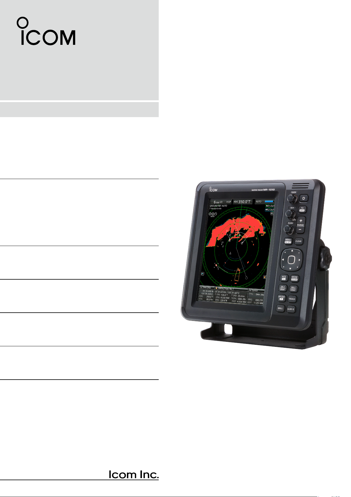
INSTRUCTION MANUAL
MARINE RADAR
MR-1010R™
Page 2

SYSTEM COMPONENTS
MODEL NAME DISPLAY UNIT SCANNER UNIT
MR-1010RII 10.4-inch Color LCD EX-2714 (Radome type)
SUPPLIED ACCESSORIES
z 10.4-inch Color LCD display unit
Quantity
1. NMEA connector (PLT-167-P-R) ........................ 1
2. NMEA connector (PLT-168-P-R) ......................... 1
3. Spare fuse (FGB 15 A) ....................................... 1
4. Spare fuse
5. DC power cable .................................................. 1
6. Mounting bracket ................................................ 1
7. Mounting knob bolts ........................................... 2
8. Installation bolts (M6×30) ................................... 5
9. Installation nuts (M6) .......................................... 5
10. Spring washers (M6) ........................................ 10
11. Flat washers (M6) ............................................. 10
12. Instruction manual .............................................. 1
13. Operating guide .................................................. 1
14. EX-2714 template ................................................ 1
15. Display unit template ........................................... 1
(FGB 5 A: for over 24 V power supply)
.. 1
z Scanner unit (EX-2714)
Quantity
1. System cable (10 m) ........................................... 1
2. Installation bolts (M10×50) ................................. 4
3. Installation bolts (M10×25) ................................. 4
4. Installation nuts (M10) ........................................ 4
5. Flat washers (M10) ............................................. 4
6. Spring washers (M10) ........................................ 4
i
Page 3
The MR-1010RII is a supplemental aid to navigation and is not intended to be a substitute
for accurate and current nautical charts.
Thank you for choosing this Icom product. The
MR-1010RII marine radar is designed and built with
Icom's state of the art technology and craftsmanship.
With proper care, this product should provide you
with years of trouble-free operation.
SART signals may not be detected and
displayed on the screen, depending on the
BE CAREFUL!
SEA, RAIN or IR settings.
IMPORTANT
READ ALL INSTRUCTIONS carefully and
completely before using the radar.
SAVE THIS INSTRUCTION MANUAL—
This manual contains important safety and operating
instructions for the MR-1010RII.
FEATURES
The radar is "Made in Japan." It has powerful
transmitting power for long range detection, a
10.4-inch wider view angle color display, simplied
ARPA to detect up to 5 targets, and other advanced
features.
EXPLICIT DEFINITIONS
WORD DEFINITION
R DANGER!
R WARNING!
CAUTION Equipment damage may occur.
NOTE
Personal death, serious injury or an
explosion may occur.
Personal injury, re hazard, or
electric shock may occur.
Recommended for optimum use. No
risk of personal injury, re or electric
shock.
Make the settings below to detect the
SART signals on the screen.
1. Set the screen range to between 6 NM
and 12 NM with [+/–]. (pp. 1, 7)
2. Set the [GAIN] as high as possible.
(pp. 2, 9)
3. Set [SEA] to minimum. (pp. 2, 9)
4. Set [RAIN] to minimum. (pp. 2, 9)
5. Turn OFF the Interference rejection
(IR) function. (p. 10)
6. Turn OFF the Echo Stretch function.
(p. 11)
Icom is not responsible for the destruction, damage
to, or performance of any Icom or non-Icom
equipment, if the malfunction is because of:
• Force majeure, including, but not limited to, res,
earthquakes, storms, oods, lightning, other
natural disasters, disturbances, riots, war, or
radioactive contamination.
• The use of Icom marine radar with any equipment
that is not manufactured or approved by Icom.
Icom, Icom Inc. and the Icom logo are registered
trademarks of Icom Incorporated (Japan) in Japan,
the United States, the United Kingdom, Germany,
France, Spain, Russia, Australia, New Zealand, and/
or other countries.
ii
Page 4

PRECAUTIONS
For Display unit:
R WARNING! NEVER let metal, wire or other
objects contact the inside of the display unit, or make
incorrect contact with connectors on the rear panel.
This could cause an electric shock or damage the
display unit.
R WARNING! NEVER apply AC voltage to the DC
connector of the display unit. This could cause a re
or damage the display unit.
R WARNING! NEVER apply more than 42 V DC
to the DC connector of the display unit. This could
cause a re or damage the display unit.
R WARNING! NEVER touch or operate the display
unit with wet hands. This could cause an electric
shock or damage the display unit.
R WARNING! NEVER open the display unit. There
are no user adjustment points. This could cause an
electric shock and incorrect reassembly may cause a
re hazard.
R WARNING! NEVER operate the radar during a
lightning storm. It may result in an electric shock,
cause a re or damage the display unit. Always
disconnect the powersource and scanner unit before
a storm.
R WARNING! NEVER reverse the DC power cable
polarity. This could cause a re or damage the display
unit.
R WARNING! NEVER remove the fuse holder on the
DC power cable. Excessive current caused by a short
could cause a re or damage the display unit.
CAUTION: DO NOT use or place the display unit in
areas with temperature below –15˚C (+5˚F) or above
+55˚C (+131˚F).
CAUTION: DO NOT
Benzine or alcohol when cleaning, the display unit, as
they will damage the display unit surfaces.
CAUTION: DO NOT place the display unit in
excessively dusty environments.
DO NOT place the display unit near heating
equipment or in direct sunlight or where hot or cold
air blows directly onto it.
DO NOT place the display unit in areas that could
block air passage or put anything around the display
unit. This will obstruct heat dissipation.
KEEP the display unit out of the reach of
unauthorized persons.
KEEP the display unit away from heavy rain, and
never immerse it in the water.
The display unit meets IPX4 requirements for splash
resistance when the supplied connection cable,
scanner unit are connected.
use harsh solvents such as
However, if it is dropped, splash resistance cannot be
guaranteed because of possible damage to the case
or the waterproof seals.
The LCD display may have cosmetic imperfections
that appear as small dark or light spots. This is not a
malfunction or defect, but a normal characteristic of
LCD display.
For Scanner unit:
R DANGER: HIGH VOLTAGE! NEVER open the
scanner unit. The scanner unit contains high voltage
that could be fatal. And there are no user adjustment
points. All repairs and adjustments MUST be made
by a qualied electronics technician at your Marine
Navigation Dealer.
For qualied electronics technician only:
R
DANGER: HIGH VOLTAGE! High voltages of up to
3,500 volts are used in the scanner unit. Although
prudent measures for safety have been adopted,
sufcient care must be taken in the operation,
maintenance and adjustment of the scanner unit.
Electric shock of 1,000 volts or more may cause
electrocution and death; even an electric shock of
only 100 volts may be fatal.
R DANGER: HIGH VOLTAGE! DO NOT turn OFF the
radar
’s power and do not reach inside the scanner
unit before you have:
• discharged the capacitors by disconnecting the
system cable from the radar unit for 5 minutes.
• checked that no electric charges remain inside
the device.
Also, it is recommended to wear dry insulated
rubber gloves. NEVER use both hands
simultaneously; keep one hand in your pocket.
R
WARNING: RADIATION HAZARD!
Radiation emitted from the scanner unit can be
harmful, particularly to your eyes. To avoid harmful
radiation, turn
working on the scanner unit.
DO NOT use or place the scanner unit in areas with
temperature below –25˚C (–13˚F) or above +70˚C
(+158˚F).
NEVER immerse the scanner unit in the water.
The scanner unit meets IPX6
pressure water jet resistance.
However, if the scanner unit is dropped, highpressure water jet resistance cannot be guaranteed
because of possible damage to the cases or the
waterproof seals.
* Except for the cable connectors. They meet IPX4
requirements while connecting to the radar unit.
OFF the radar’s power
*
requirements for high-
before
iii
Page 5

TABLE OF CONTENTS
SYSTEM COMPONENTS .......................................... i
SUPPLIED ACCESSORIES ....................................... i
IMPORTANT ...............................................................ii
FEATURES .................................................................ii
EXPLICIT DEFINITIONS ............................................ii
PRECAUTIONS .........................................................iii
PANEL DESCRIPTIONS .................................. 1–6
1.
Front panel ........................................................ 1
■
Screen .............................................................. 3
■
BASIC OPERATION ...................................... 7–16
2.
Turning the Power ON or OFF .......................... 7
■
Basic operation ................................................. 7
■
Adjusting brilliance and color ............................. 8
■
Adjusting the screen ......................................... 9
■
OFF CENTER function ................................... 10
■
Zoom function ................................................ 10
■
Interference Rejection function ....................... 10
■
Echo Stretch function .......................................11
■
Long pulse function ..........................................11
■
Trail function ................................................... 12
■
Power save function ....................................... 13
■
Ship speed indication ...................................... 14
■
Waypoint indication ......................................... 14
■
Bearing settings .............................................. 15
■
DISTANCE AND DIRECTION MEASUREMENTS ..17–20
3.
Distance measurement ................................... 17
■
Bearing and Distance measurement .............. 18
■
Advanced measurements ............................... 19
■
ALARM FUNCTION ..................................... 21–22
4.
Setting the Alarm zone .................................... 21
■
Setting Zone alarm type .................................. 22
■
THE SIMPLIFIED ARPA OPERATION ........ 23–25
5.
ARPA operation............................................... 23
■
Descriptions of ARPA targets .......................... 24
■
ARPA settings ................................................. 25
■
Related settings .............................................. 25
■
AIS RECEIVER ............................................ 26–31
6.
About AIS ........................................................ 26
■
AIS operation .................................................. 26
■
Description of the AIS display ......................... 27
■
AIS settings ..................................................... 29
■
Related settings .............................................. 31
■
OTHER FUNCTIONS ................................... 32–38
7.
Receiving DSC Information ............................ 32
■
TLL function .................................................... 33
■
Select the language ........................................ 34
■
Simulation mode ............................................. 34
■
Antenna rotation speed ................................... 35
■
Timing adjustment ........................................... 35
■
Heading adjustment ........................................ 36
■
Range selection .............................................. 37
■
Save and load settings ................................... 37
■
Resetting ......................................................... 38
■
MENU SCREEN ........................................... 39–46
8.
Operation in the Menu screen ........................ 39
■
Color menu ..................................................... 39
■
Trail menu ....................................................... 40
■
Display menu .................................................. 40
■
Target menu .................................................... 41
■
ARPA menu..................................................... 41
■
AIS menu ........................................................ 42
■
Video menu ..................................................... 43
■
System menu .................................................. 43
■
Initial menu ..................................................... 45
■
AIS Own menu ................................................ 46
■
Status menu .................................................... 46
■
Port Monitor menu .......................................... 46
■
Scanner Monitor menu ................................... 46
■
BASIC RADAR THEORY ............................ 47–49
9.
Sidelobe echoes ............................................. 47
■
Indirect echoes ............................................... 47
■
Multiple echoes ............................................... 48
■
Minimum range ............................................... 48
■
Blind and Shadow sectors .............................. 48
■
Target resolution ............................................. 49
■
MAINTENANCE ................................................. 50
10.
Periodic maintenance ..................................... 50
■
Scanner unitmaintenance ............................... 50
■
Display unit maintenance ................................ 50
■
ERROR MESSAGES ......................................... 51
11.
Error message list ........................................... 51
■
AIS error message list .................................... 51
■
SPECIFICATIONS.............................................. 52
12.
General ........................................................... 52
■
Display unit ..................................................... 52
■
Scanner unit (EX-2714) .................................. 52
■
Options ........................................................... 52
■
EXTERNAL DATA LIST ..................................... 53
13.
INSTALLATION AND CONNECTIONS ....... 54–60
14.
Connecting the units ....................................... 54
■
Power source requirement .............................. 54
■
Ground connection ......................................... 54
■
Installing the display unit ................................. 55
■
Mounting the EX-2714 scanner unit ............... 57
■
Wiring the EX-2714 system cable .................. 58
■
Installing the UX-252 Video output unit .......... 59
■
Checking the installation ................................. 60
■
NDEX....................................................................... 61
(Appendices)
• Display mounting bracket template
• MR-1010RII OPERATING GUIDE
iv
Page 6
1
q
w
t
u
y
Control panel (English) Control panel (Chinese)
r
i
o
!0
!7
!8
!6
!5
!4
!3
!2
!1
e
q
w
t
u
y
r
i
o
!0
!7
!8
!6
!5
!4
!3
!2
!1
e
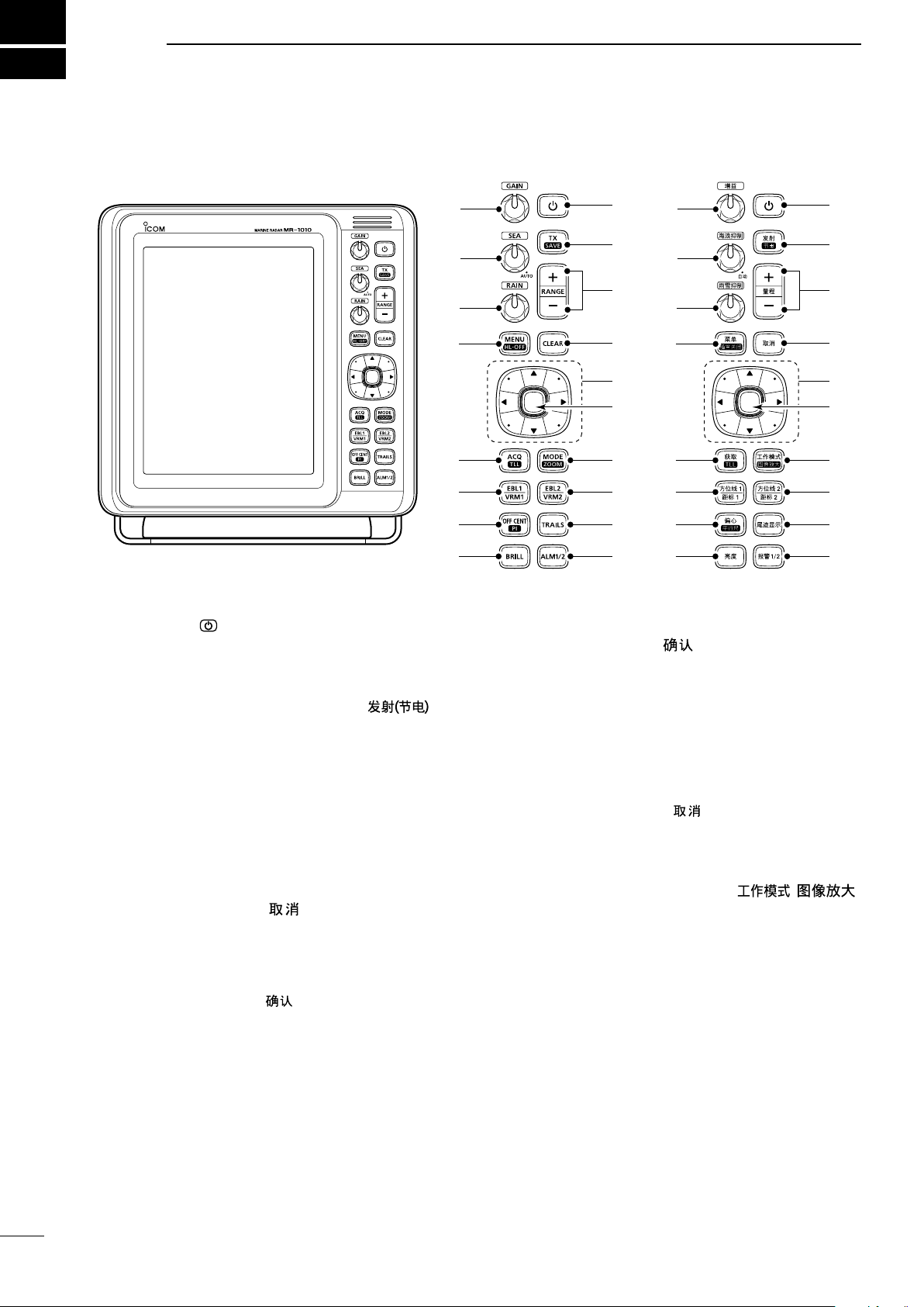
PANEL DESCRIPTIONS
■ Front panel
q POWER KEY (p. 7)
z Push to turn the radar power ON or OFF.
• The initial screen is displayed and a beep sounds
after the power has been turned ON.
w TRANSMIT/SAVE KEY [TX (SAVE)]/ [ ]
z Push to toggle between the TX mode and the
standby mode. (p. 7)
z Hold down for 1 second to turn ON the power
save function. The radar for the TX interval scan
is xed at 10 revolutions. (p. 13)
L Select the save time in the System menu.
e RANGE UP/ DOWN KEYS [+]/[–] (p. 7)
z Push [+] to increase the screen range.
z Push [–] to decrease the screen range.
r CLEAR KEY [CLEAR]/[
]
z Push to cancel the Submenu or Option selection
mode in the Menu screen. (p. 39)
z Hold down for 1 second to turn the activated AIS
target into a sleeping target. (p. 26)
L Hold down [ENTER]/[ ] for 1 second to change
the sleeping AIS target to an activated target.
z Hold down for 1 second to release the ARPA
target or delete the TLL symbol. (pp. 23, 33)
t CURSOR PAD
z Push to move the cross-line cursor
directions
in the normal operating mode.
in sixteen
z Sets the EBLs, VRMs, alarm area, ARPA target,
AIS target, and so on.
z Push [t] or [u] to select the Menu group, or
push [p] or [q] to select the menu items in the
y ENTER KEY*
*Described as [ENTER]/[ ] in this manual.
Push to select the target and display the ARPA,
AIS, DSC, TLL, or WPT information. (pp. 14, 23,
26, 33)
z In the Menu screen, push to display a submenu
or option selection mode, or push to save the
settings. (p. 39)
z Hold down for 1 second to turn the sleeping AIS
target into an activated target. (p. 26)
L Hold down [CLEAR]/[ ] for 1 second to change
the activated AIS target to a sleeping target.
z Hold down for 1 second to display the DSC
details. (p. 32)
MODE / ZOOM KEY [MODE•ZOOM]/
u
z Push to select the screen mode, Head-up (H-
[ • ]
UP), Course-up (C-UP), North-up (N-UP) or True
motion (TM) screen. (p. 7)
z Hold down for 1 second to toggle the ZOOM
view ON or OFF. The ZOOM view expands the
Plain Position Indicator (PPI) and the trail around
L The North-up, and Course-up screens can
be selected only when a bearing data input is
connected. (pp. 45, 53)
L The TM screen requires bearing data and position
data.
L TheTM screen is not selectable in the 32 NM or
higher range.
the cross-line cursor to the double size of the
normal view. (p. 10)
Menu screen. (p. 39)
1
Page 7
PANEL DESCRIPTION
RAIN
SEA
GAIN
1
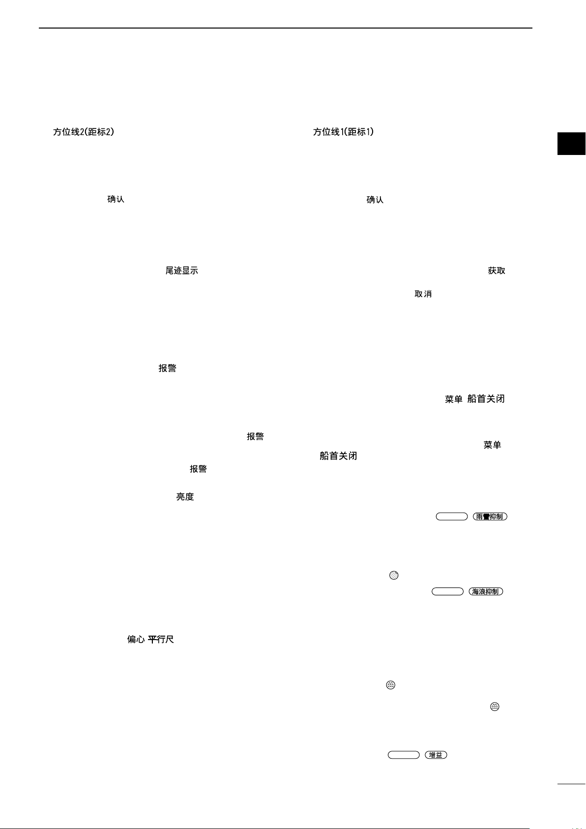
i EBL2 (VRM2) KEY [EBL2 (VRM2)]/
[
z Push to display the EBL2 and the VRM2.
EBL: Electronic Bearing Line
VRM: Variable Range Marker
• Push [t] or [u] to adjust the EBL selector, or push
[p] or [q] to adjust the VRM selector. Then push
[ENTER]/[
• The EBL2 bearing and the VRM2 distance are
displayed in the lower right corner of the screen.
• When EBL1 and VRM1 are displayed, the center of
the VRM2 appears at the intersection point of the
EBL1 and the VRM1.
o TRAILS KEY [TRAILS] / [ ](p. 12)
z Push to turn the trail function ON or OFF. This
is useful for watching other ship’s tracks, and
approximate relative speed.
L The Trail settings can be changed in the Trail
menu.
z Hold down for 1 second to erase the plotted
echoes when the trail function is ON.
!0 ALARM KEY [ALM1/2]/[
z Push to select the Alarm function, ALM1, ALM2,
ALM1 & ALM2, or OFF.
z Hold down for 1 second to enter the alarm zone
setting mode.
• Push the cursor pad to move the cross cursor to the
zone starting point, then hold down [ALM1/2]/[
1/2] for 1 second. The frame of the entered zone
appears. Then push the cursor pad to x the nish
point, and then push [ALM1/2]/[
zone will automatically be formed.
!1 BRILLIANCE KEY [BRILL]/[ ] (p. 8)
z Push to display the Brill/Color setting box.
L The brilliance of the display, the key backlight, and
display color can be adjusted in the setting box.
L The brightness of the symbols, characters and
illuminations can be independently adjusted in the
Color menu.
z Push to increase or decrease the brilliance of
the display.
z Hold down for 1 second to select the maximum
brilliance.
!2 OFF CENTER / PARALLEL INDEX LINE KEY
[OFF CENT•PI]/ [
z Push to turn the OFF CENTER function ON or
OFF.
L This function is usable in the 24 NM or less ranges.
z Hold down for 1 second to display or clear the
parallel index lines.(p.17)
] (pp. 17–20)
] to set the point.
1/2](pp. 21–22)
1/2]. The alarm
• ] (p. 10)
!3 EBL1 (VRM1) KEY [EBL1 (VRM1)]/
[
z Push to display the EBL1 and the VRM1.
EBL: Electronic Bearing Line
VRM: Variable Range Marker
• Push [t] or [u] to adjust the EBL selector, or push
[p] or [q] to adjust the VRM selector. Then push
[ENTER]/[
• The EBL1 bearing and the VRM1 distance are
displayed in the lower left corner of the screen.
• When the EBL1 and the VRM1 are displayed, the
beginning of the EBL2 appears at the intersection
point of the EBL1 and the VRM1.
!4
ACQUIRE TARGET / TLL KEY [ACQ/TLL]/ [ •TLL]
z Push to acquire an ARPA target on the cursor.
L Hold down [CLEAR]/[ ] for 1 second to release
the ARPA target.
z Hold down for 1 second to output the position
information where the cursor is placed, to the
NMEA output terminals. (p. 23)
L TLL output requires bearing data and position data.
L The target symbol can be displayed, depending on
the setting in the “TLL Mode” item of the System
menu. (p. 33)
!5 MENU KEY [MENU/HL-OFF]/[ • ]
z Push to enter or exit the Menu screen. (p. 39)
z Push [t] or [u] to select the Menu groups, or
push [p] or [q] to select the items.
z While holding down [MENU•HL_OFF]/[ •
OFF.(p.9)
L The rings or other objects can also be turned OFF
when the “HL OFF Mode” item in the System menu
is set to “All.” (p. 44)
!6 RAIN CLUTTER CONTROL
(p. 7, 9)
Eliminates echoes from rain, snow, fog, and so on.
z Rotate the control fully counter clockwise to
deactivate the RAIN function.
• The RAIN icon ( ) disappears.
!7 SEA CLUTTER CONTROL
(p. 7, 9)
Eliminates echoes from waves in close range.
Reduces the receiver gain for close objects within a
radius of approximately 8 nautical miles to eliminate
sea clutter.
z Rotate the control fully clockwise to activate the
automatic SEA control function.
• The SEA icon ( ) is displayed in the upper left of
the screen.
• “AUTO” is displayed below the SEA icon (
the automatic control function is active.
L Under normal conditions set the SEA to minimum.
L Use this control with caution when the sea is rough.
] (pp. 17–20)
] to set the point.
], the heading line is temporarily turned
/
/
) when
1
2
3
4
5
6
7
8
9
10
11
12
13
14
15
16
17
18
19
20
21
!8 GAIN CONTROL
Adjusts the receiver amplier gain.
z Rotate clockwise to increase the gain.
L The increased gain may increase screen noise.
/ (p. 7, 9)
2
Page 8
1
PANEL DESCRIPTION
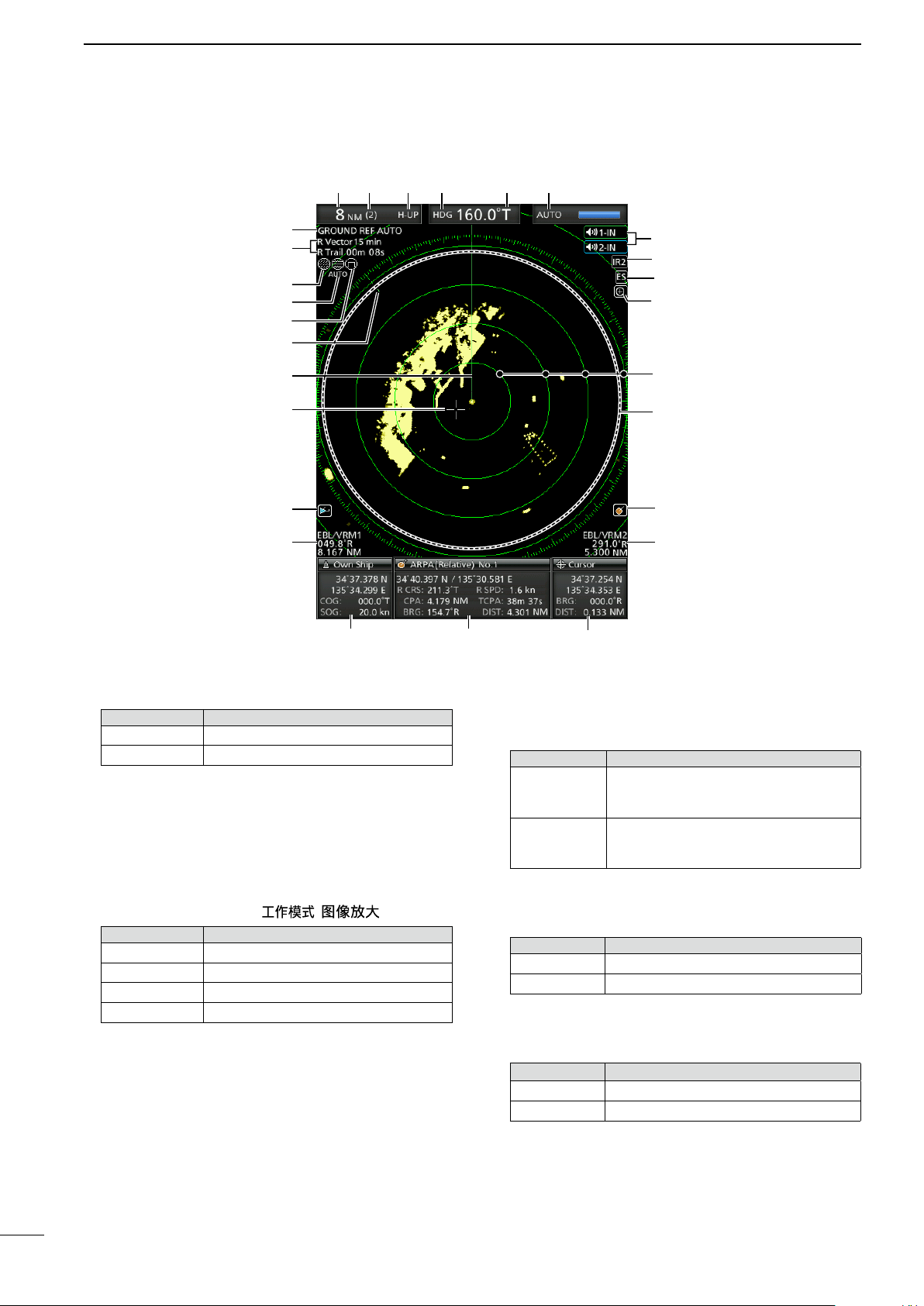
■ Screen
q t yw e r
u
i
o
!0
!1
!2
!3
!4
!5
!6
!7
!8
!9
@7
@6
@5
@4
@3
@2
@1
@0
This Display example is
set to Wide in the “PPI
Area” item of the Display
menu.
q SCREEN RANGE READOUT (p. 17)
Displays the range of the current screen.
Indicator Description
NM nautical miles
km kilometers
L The distance unit can be selected in the Initial menu.
w FIXED RING RANGE READOUT (p. 17)
Displays the interval range of the xed ring.
e MODE INDICATOR (p. 7)
Displays the mode of the display.
Push [MODE•ZOOM]/ [ • ] to select.
Indicator Description
H-UP Head-up
C-UP Course-up
N-UP North-up
TM True Motion
L N-UP and C-UP screens require external bearing data.
L The TM screen requires bearing data and position
data.
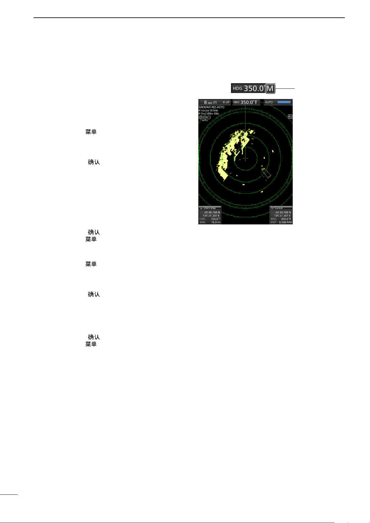
r HEADING INDICATOR (p. 15)
Displays the heading readout.The HDG readout
indicates the bow of the ship’s heading in a
clockwise direction from north.
Indicator Description
Displayed when the “Bearing Input” in
HDG
COG
the Initial menu is set to “NMEA,” “N+1,”
or “AUX.”
Displayed When the “Bearing Input”
item in the Initial menu is set to “GPS”
or “GPS-L.”
t BEARING REFERENCE (p. 15)
Displays the bearing reference.
Indicator Description
T True bearing
M Magnetic bearing
y TUNING MODE INDICATOR (p. 9)
Displays the tuning mode and the tuning level.
Indicator Description
Auto Auto tuning
Manual Manual tuning
• “TUNE (AUTO)” is displayed when the “TUNE” item
in the Video menu is set to “Auto” or “TUNE (MAN)” is
displayed when the “TUNE” item is set “Manual.”
u REFERENCE INDICATOR (p. 15)
Displays the basis of vector reference.
3
Page 9
PANEL DESCRIPTION
1
i TRAILS INDICATOR (p. 12)
Displays the trail reference and the trail time.
• The echo remains, with gradation, during the trail time
period on the screen. (Except for the trail time; ∞)
• Progressing time counter starts counting until the timer
reaches the trail time.
Indicator Description
T True
M Magnetic
o RAIN CONTROL ICON (p. 9)
Displayed when the RAIN function is in use.
!0 SEA ICON (p. 9)
Displayed when the SEA control function is in use.
“AUTO” is displayed below the icon when the
automatic SEA control function is in use.
!1 LONG PULSE ICON (p. 9)
Displayed when the long pulse is in use.
!2 NORTH MARK
The north mark indicates the true north direction.
!3 HEADING LINE (p.16)
The heading line indicates the ships bow direction.
!4 CROSS-LINE CURSOR
Used to measure the bearing and distance, setting
the alarm zone, selecting the ARPA/AIS targets,
and so on.
L The cross-line cursor can be moved to sixteen
directions by pushing or holding a cursor pad.
!8 INFORMATION BOX (pp. 14, 23, 26, 32)
Displays a detailed information of a selected target,
such as AIS, ARPA, TLL, Waypoint, or, DSC.
L Refer to each section in this manual for details on the
displayed information in each function.
!9 CURSOR INFORMATION
The current position of the cross-line cursor is
displayed.
L Latitude and longitude (Lat/Lon) or Time to go (TTG)
can be selected as the position format.
L An external NMEA data in 0183 format is required.
• Displays the bearing and distance to the cross-line
cursor.
Indicator
R Relative bearing
T True bearing
M Magnetic bearing
L Bearing data and position data are required.
@0 EBL2/ VRM2 READOUTS (pp. 17–20)
Displays the bearing of the Electronic Bearing Line
(EBL) 2 and the distance of the Variable Range
Marker (VRM) 2 when the EBL2 and the VRM2 are
set.
L Nautical miles (NM) or kilometers (km) can be
selected as the distance unit in the Initial menu.
@1 ARPA ICON (p. 23)
Displayed when one or more targets are
automatically acquired by auto acquire function.
@2 PLAIN POSITION INDICATOR SCOPE AREA
Displays the radar picture and plots the data such
as vessels, bases, and so on.
Description
1
2
3
4
5
6
7
8
9
10
11
12
13
14
15
!5 AIS ICON (p. 26)
Displayed when a valid VDM sentence is input
from the [NMEA1] (AIS) port.
The indicator disappears if the AIS signal is not
received for 6 minutes and 40 seconds.
!6 EBL1/ VRM1 READOUTS (pp. 17–20)
Displays the bearing of the Electronic Bearing Line
(EBL) 1 and the distance of the Variable Range
Marker (VRM) 1, when the EBL1 and the VRM1
are in use.
L Nautical miles (NM) or kilometers (km) can be
selected in the Initial menu as the distance unit in the
Initial menu.
!7 OWN SHIP INFORMATION
Displays your own ship’s latitude and longitude,
course, and speed.
L To display the position, NMEA 0183 data is required.
L The speed unit in nautical miles (kn) or kilometers
(km/h) can be selected as the speed unit in the Initial
menu.
@3 FIXED RANGE RINGS (p. 25)
Displays the distance at xed intervals from the
own position. The interval distance is indicated by
the ring range readout (w).
L These rings are displayed when the “Ring Brill” item
in the Color menu is set to ON (1 to 3).
@4 ZOOM ICON (p. 10)
Displayed when the zoomed view is activated.
@5 ECHO STRETCH ICON (p. 11)
Displayed when the echo stretch function is in use.
@6 IR1 / IR2 ICONS / (p. 10)
Displayed when the Interference Rejection (IR)
function 1 or 2 is turned ON.
@7 ALARM1 / ALARM2 ICONS /
(p.
21–22)
Displayed when the alarm 1 or 2 is set.
16
17
18
19
20
21
4
Page 10
1
PANEL DESCRIPTION
■ Screen (Continued)
#2
#38
@8
@9
#0
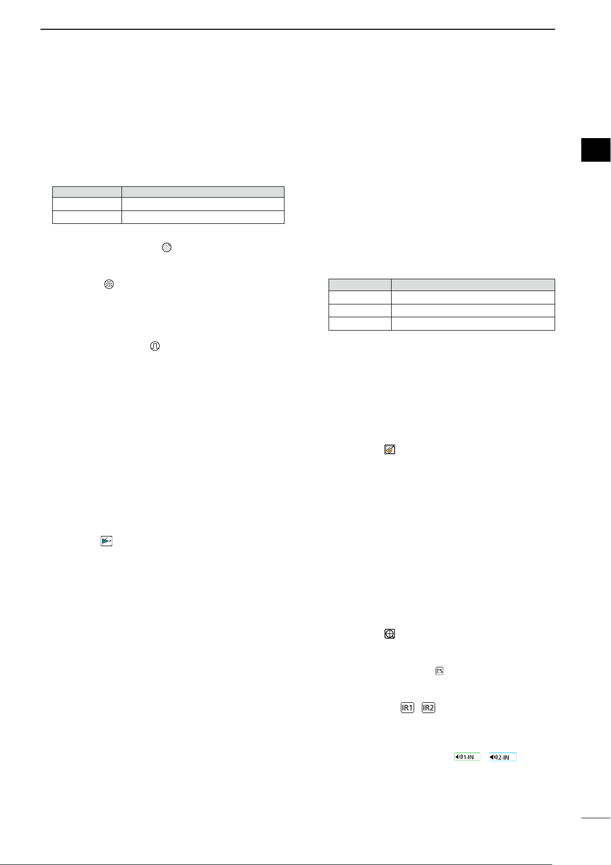
@8 OWN SHIP VECTOR INDICATOR (p. 6)
Displays the vector of your own ship.
@9 PARALLEL INDEX LINES (p. 17)
Displayed when the Parallel Index line (PI) function
is in use. Used to measure the direction and
interval of the parallel index lines
#0 PI READOUTS (p. 17)
Displays the direction and interval of the parallel
index lines when the Parallel Index line (PI)
function is set.
#4
#1
#5
!6
#1 WAYPOINT MARKER (p. 14)
Displays a waypoint that is received from
@0
navigation equipment.
• This marker is displayed when the “WPT Display” item
in the Display menu is set to ON.
• To display the Waypoint marker, bearing data and
NMEA data in 0183 format are required. (p. 53)
#2 EBL1 (pp. 17–20)
#3 EBL2 (pp. 17–20)
Used to measure bearing.
When a target is selected, the EBL/VRM1 readouts
(!6) or the EBL/VRM2 readouts (@0) display its
bearing.
#4 VRM1 (pp. 17–20)
#5 VRM2 (pp. 17–20)
Used to measure distance.
When a target is selected, the EBL/VRM1
readouts (!6) or the EBL/VRM2 readouts (@0)
display its distance.
5
5
Page 11
PANEL DESCRIPTION
1
1
2
3
4
#6
#7
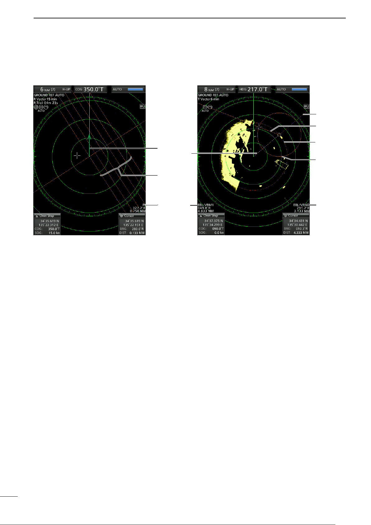
#6 ALARM ZONE (p. 14)
Displays the alarm zone.
• Displays when the alarm function is in use.
#7 WARNING MESSAGE (p. 22)
Displayed at the bottom of the screen when an
alarm sounds in case such as a vessel is entered
into the zone that you have set.
• Push [CLEAR]/[ ] key to stop the alarm sound and
close the displayed message.
#8
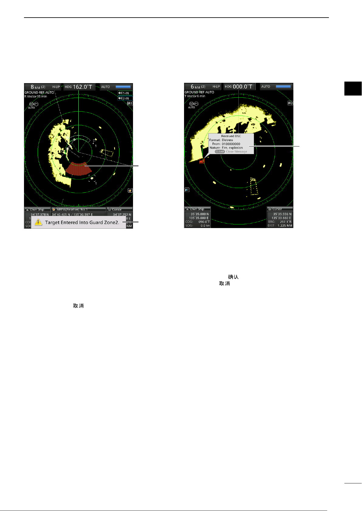
#8 POPUP MESSAGE (p. 32)
A message pops up when the radar received the
data of the target, such as a DSC, or favorite AIS
that you have selected.
• Push [Enter]/[ ] to display the details, or push
[CLEAR]/[
the displayed message.
] key to stop the alarm sound and close
5
6
7
8
9
10
11
12
13
14
15
16
17
18
19
20
21
6
6
Page 12
2
GAIN
SEA
RAIN
BASIC OPERATION
■ Turning the Power ON or OFF
Refer to Chapter 14 in this manual about the
installation and connections. (pp. 54–60)
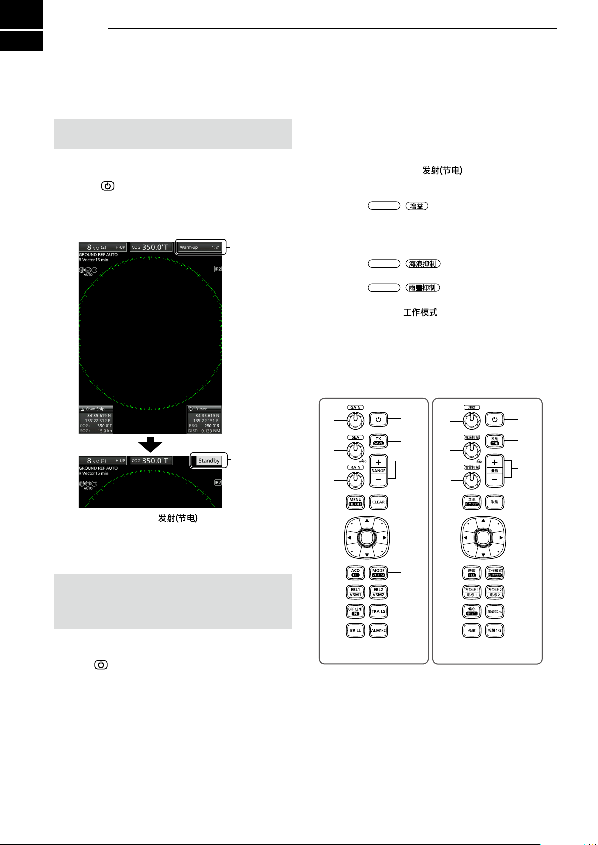
Turning ON the power
1. Push [
• The magnetron inside the scanner unit warms up for
90 seconds and the warm-up time is counted down
on the screen. When the countdown is completed, the
Standby screen is displayed.
] to turn ON the power.
Warm-up
time
■ Basic operation
1. Turn ON the power. (q)
• Standby indicator is displayed after the Warm-up is
completed.
2. Adjust the display brilliance and color. (w)
3. Push [TX (SAVE)]/[ ]. (e)
4. Push [+] several times until the maximum display
range is selected. (r)
5. Rotate
6. Push [+] or [–] several times to select a desired
display range. (y)
L The screen range readout shows the range of the
screen.
7. Rotate
control to minimum. (u)
8. Rotate
control to minimum. (i)
9. Push [MODE]/[ ] to select either the Head-
up: H-UP, Course-up: C-UP, North-up: N-UP or
True Motion: TM screen. (o)
L C-UP or N-UP can be selected only when bearing
data is provided. TM can be selected only when
bearing and position data is provided.
(See page 53 for details)
/ to adjust the gain. (t)
/
/ to set the rain clutter
to set the sea clutter
Standby
indicator
2. Push [TX (SAVE)]/[ ] to start scanning.
• Targets and heading markers are displayed.
• The screen is displayed approximately 2 seconds
after turning ON the power, when “Auto” is selected in
the “TUNE” item of the Video menu.
NOTE: At the rst turning ON the MR-1010RII or
after performing Factory Reset, the Initial Setting
screen is displayed. Push [p] or [q] to select a
language, and push [ENTER]. (p. 38)
Turning OFF the power
z Push [
] to turn OFF the power.
t
u
i
w
(English)
q
e
ry ry
t
u
i
w
(Chinese)
q
e
oo
7
Page 13
■ Adjusting brilliance and color
BASIC OPERATION
2
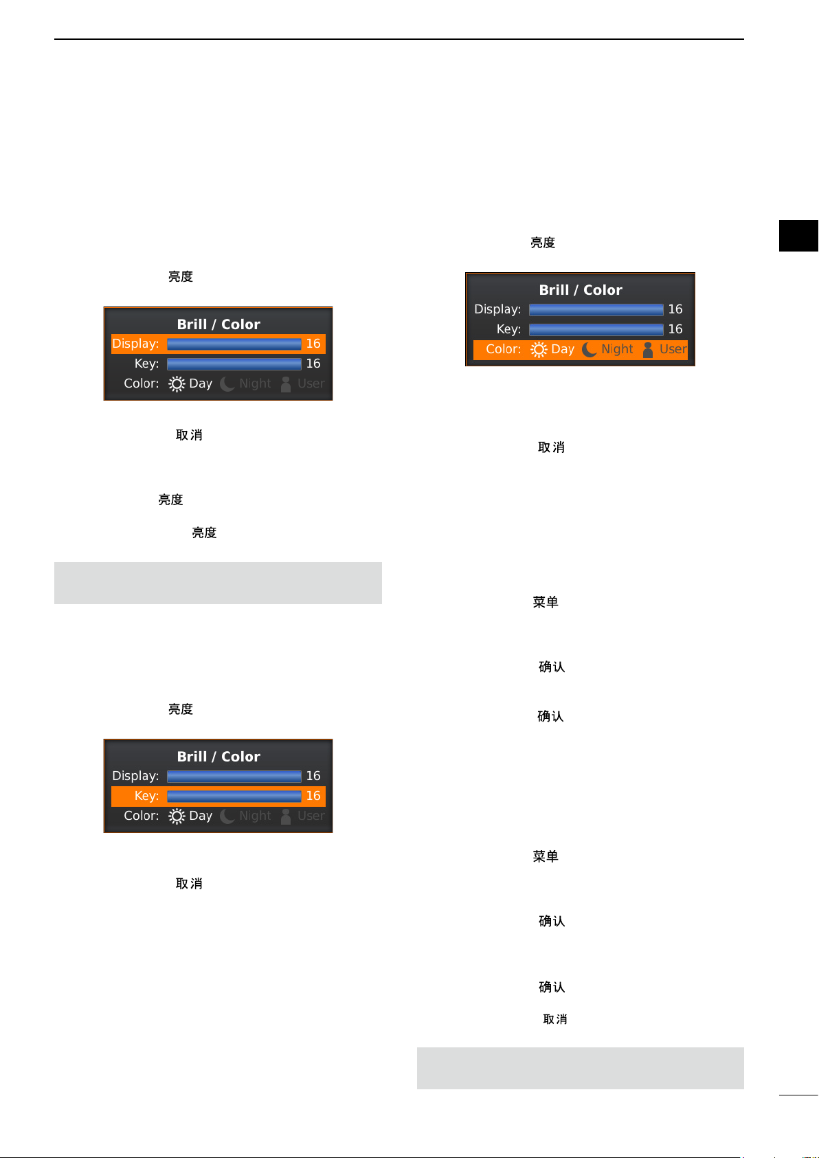
D Adjusting the display brilliance
The brilliance of the screen can be adjusted. When
you require continuous operation, but not constant
viewing, a lower setting can increase the life of the
LCD.
1. Push [BRILL]/[
adjustment box.
2. Push [t] or [u] to adjust the display brilliance.
3. Push [CLEAR]/[ ] to close the box.
• The display automatically closes the box if you don’t
push any keys for 5 seconds.
z Push [BRILL]/[ ] to increase or decrease the
display brilliance.
z Hold down [BRILL]/[ ] for 1 second to select
maximum brilliance.
NOTE: High intensity will shorten the life of the LCD
display.
] to open the Brilliance/Color
D Adjusting the key backlight
The brilliance of the key backlight can be adjusted for
your convenient operation.
1. Push [BRILL]/[ ] to open the Brilliance/Color
adjustment box.
D Selecting the display color
The Day (white background), Night (black
background), and User settings are selectable.
1. Push [BRILL]/[ ] to open the Brilliance/Color
box.
2. Push [q] twice to select the “Color” item.
3. Push [t] or [u] to select a display color.
L You can set the display color to the Day, Night, or
User.
4. Push [CLEAR]/[ ] to close the box.
• The display automatically closes the box if you don’t
push any keys for 5 seconds.
D Customizing the Display color
You can customize the foreground and background
color of each color setting, in the Color menu.
See the “Menu Screen” for details. (pp.39–40)
(MENU w Color)
1. Push [MENU]/[ ] to display the Menu screen.
2. Push [t] or [u] to select the Color menu.
3. Push [p] or [q] to select the Color settings.
• The selected item is highlighted.
4. Push [ENTER]/[ ] to enter the option selection
mode.
5. Push [t] or [u] to a desired display color, then
push [ENTER]/[ ].
1
2
3
4
5
6
7
8
9
10
11
12
13
14
15
16
2. Push [q] to select the “Key” item.
3. Push [t] or [u] to adjust the key backlight.
4. Push [CLEAR]/[ ] to close the box.
• The display automatically closes the box if you don’t
push any keys for 5 seconds.
D Brilliance of the xed range rings
The xed range rings can be used for rough distance
measurements. (p. 25)
The brilliance of the xed range rings can be adjusted
or turned OFF.
(MENU w Color w Ring Brill)
1. Push [MENU]/[ ] to display the Menu screen.
2. Push [t] or [u] to select the Color menu.
3. Push [p] or [q] to select the “Ring Brill” item.
• The selected item is highlighted.
4. Push [ENTER]/[ ] to enter the option selection
mode.
5. Push [t] or [u] to select a Ring Brilliance 1, 2, 3
or O FF.
6. Push [ENTER]/[ ] to save the setting and exit
the option selection mode.
L Push [CLEAR]/[ ] to cancel the setting and exit
the mode.
NOTE: Refer to Chapter 3 for details on the xed
range ring settings. (p.17)
17
18
19
20
21
8
Page 14
2
GAIN
SEA
Adjust SEA control
Echoes from sea waves
SEA
SEA
RAIN
Adjust RAIN controlSmall echoes
BASIC OPERATION
■ Adjusting the screen
The followings are typical basic operation examples
that may hinder radar reception (sea clutter,
precipitation interference and echoes from other
radar). See also Basic Radar Theory in Chapter 9
(pp. 47–49)
D Adjusting the GAIN
z Rotate the
increase, or counter clockwise to decrease the
gain.
L The increased gain may increase screen noise.
Adjust the gain to the point where the screen noise
just disappears.
/
control clockwise to
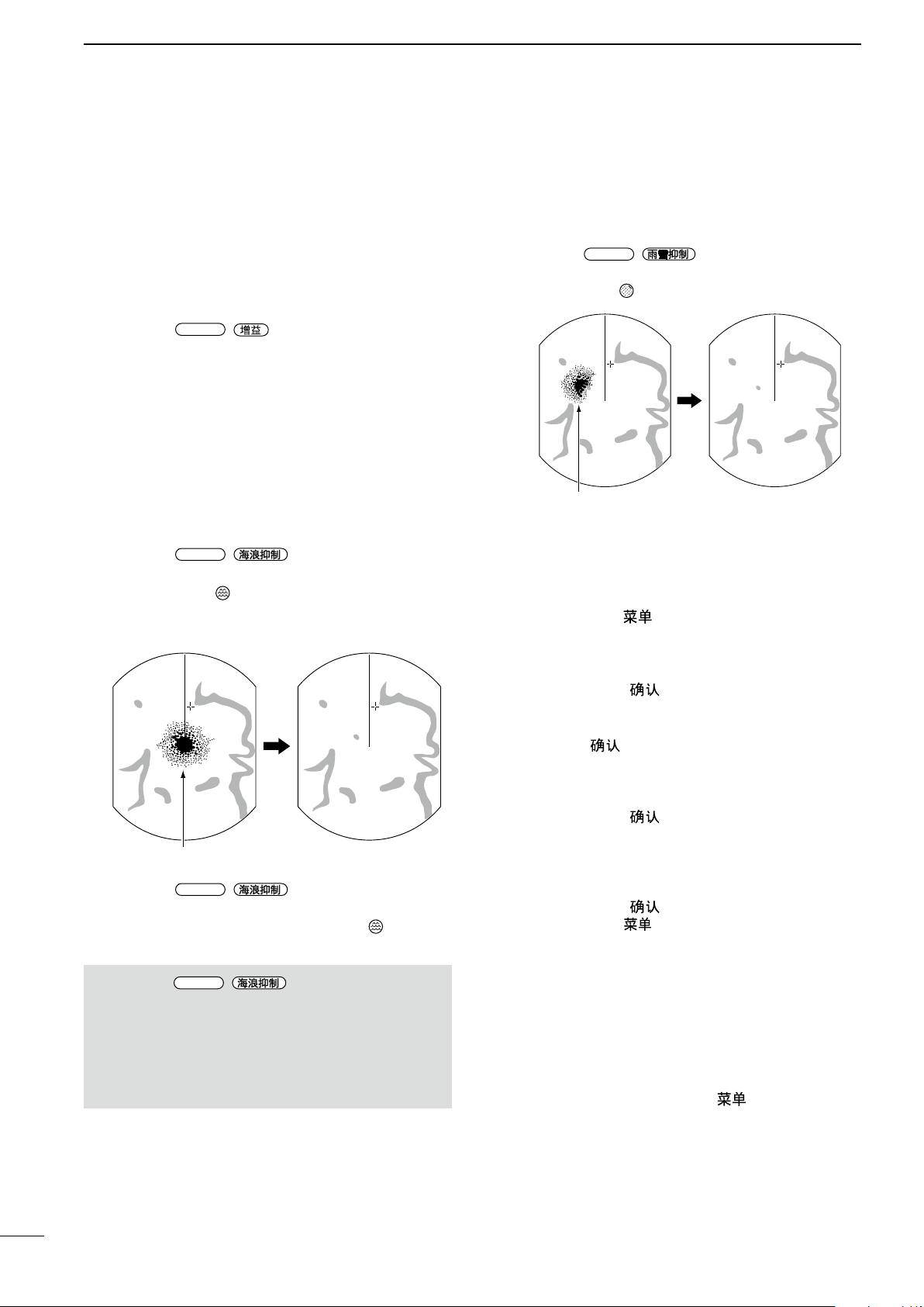
D SEA function
The SEA function eliminates echoes from waves
at close range. Reduce the receiver gain for close
objects within a radius of approximately 8 NM to
eliminate sea clutter.
z Rotate the
echoes from sea waves disappears.
• The SEA icon ( ) is displayed in the upper left
corner of the screen when the SEA function is
active.
z Rotate the
to activate the automatic control.
• “AUTO” is displayed below the SEA icon ( ) when the
automatic control function is active.
NOTE: The
receiver sensitivity of objects within approximately
8 NM. Therefore, when the SEA setting is set to too
high, close targets are blanked.
Small objects may not be displayed on the screen
when strong echoes from rain or islands within 1
NM while the automatic SEA function is activated.
/
/
/
control until the
control fully clockwise
control reduces the
D RAIN function
This function eliminates echoes from rain, snow, fog,
and so on.
z Rotate the
/ control fully
counterclockwise to deactivate the control function.
• The RAIN icon ( ) disappears.
D Manual tuning
The receiver tuning can be manually adjusted.
(MENU w Video w Tune)
1. Push [MENU]/[ ] to display the Menu screen.
2. Push [t] or [u] to select the Video menu.
3. Push [p] or [q] to select the “TUNE” item.
• The selected item is highlighted.
4. Push [ENTER]/[ ] to enter the option selection
mode.
5. Push [t] or [u] to select “Manual,” then push
[ENTER]/[ ].
• “TUNE (MAN)” is displayed at the top of the screen.
6. Push [q] to select the “Manual TUNE” item.
• The selected item is highlighted.
7. Push [ENTER]/[ ] to enter the option selection
mode.
• If the “TUNE” item is set to “Auto,” you cannot enter
the option selection mode.
8. Push [t] or [u] to adjust the tuning level. (p. 44)
9. Push [ENTER]/[ ].
10. Push [MENU]/[ ] to exit the Menu screen.
D Heading marker
The heading marker is a line that indicates your
vessel’s bow direction. This marker will be displayed
on the center of the screen when the Head-up
screen: H-UP is selected. You can temporarily hide
the heading marker when the target is located under
the heading marker. The heading marker is hidden
while holding down the [MENU]/[ ] key.
9
Page 15
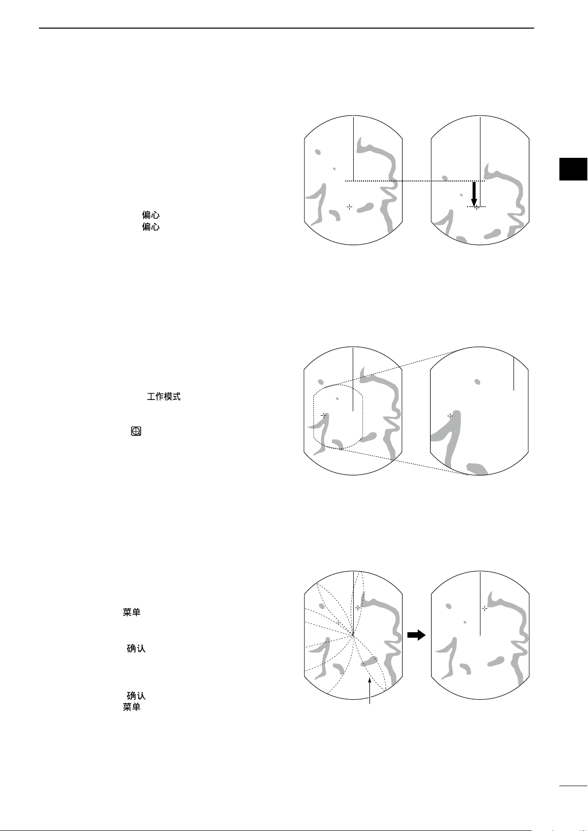
■ OFF CENTER function
OFF center view
Normal view
Zoomed view
Normal view
With IR function ON
Radar interference
The scanning area can be shifted in direction and
can be partially enlarged. This is useful when the
Head-up screen is selected, and you want to enlarge
the bow direction display, or the center of the screen
shifts in the direction of the intersection.
L This function is selectable in 24 NM or shorter ranges.
L This function is not selectable in the TM screen.
BASIC OPERATION
2
1
2
3
1. Push [OFF CENT]/[ ] to shift the screen.
2. Push [OFF CENT]/[ ] again to return to the
normal screen.
The OFF center mode setting can be changed in the
“OFF Center Mode” item in the System menu.
• 25%, 50%, 75%, and Cursor are selectable.
■ Zoom function
The Zoom function expands the target to two times
normal view.
1. Move the cross-line cursor to a desired target.
2. Hold down [MODE]/[ ] for 1 second to
toggle between the zoomed view and the normal
view.
• The ZOOM icon ( ) is displayed in the upper right of
the screen.
4
5
6
7
8
9
10
11
12
13
14
15
■ Interference Rejection function
Radar interference may appear when another
vessel’s radar is operating on the same frequency
band in close proximity. The Interference Rejection
(IR) function can eliminate this type of interference.
1. Push [MENU]/[ ] to display the Menu screen.
2. Push [t] or [u] to select the Video menu.
3. Push [p] or [q] to select the “IR” item.
4. Push [ENTER]/[ ] to enter the option selection
mode.
5. Push [t] or [u] to select the IR function 1, 2, or
OF F.
6. Push [ENTER]/[ ] to save the setting.
7. Push [MENU]/[ ] to exit the Menu screen.
• “IR1” or “IR2” indicator is displayed in the upper right
of the screen, when the function is activated.
(MENU w Video w IR)
16
17
18
19
20
21
10
Page 16
2
With Echo Stretch ON
Normal screen
BASIC OPERATION
■ Echo Stretch function
The blips can be magnied electronically for easier
viewing of small targets.
1. Push [MENU]/[ ] to display the Menu screen.
2. Push [t] or [u] to select the Video menu.
3. Push [p] or [q] to select the “Echo Stretch” item.
4. Push [ENTER]/[ ] to enter the option selection
mode.
5. Push [t] or [u] to select the Echo Stretch ON.
6. Push [ENTER]/[ ] to save the setting.
7. Push [MENU]/[ ] to exit the Menu screen.
• “ES” is displayed in the upper right of the screen,
when the function is activated.
NOTE: Turn OFF this function during normal
operation.
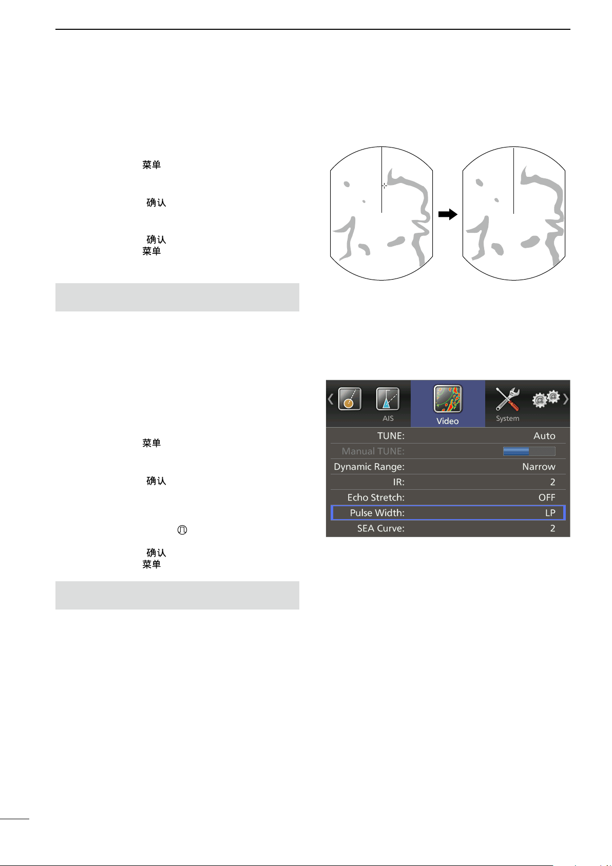
■ Long pulse function
To magnify the blips for easier viewing of small
targets, the long pulse and echo stretch functions are
usable. When the long pulse is used in the 3⁄4 to 3 NM
range, this function magnies target echoes behind
the target.
(MENU w Video w Echo Stretch)
(MENU w Video w Pulse Width)
1. Push [MENU]/[ ].
2. Push [t] or [u] to select the Video menu.
3. Push [p] or [q] to select the “Pulse Width” item.
4. Push [ENTER]/[ ] to enter the option selection
mode.
5. Push [t] or [u] to select SP (Short Pulse) or LP
(Long Pulse).
• When “LP” is selected, “ ” appears in the upper left
of the screen.
6. Push [ENTER]/[ ] to save the setting.
7. Push [MENU]/[ ] to exit the Menu screen.
NOTE: Selecting SP (Short Pulse) increases the
target distance resolution. (p. 43)
11
Page 17
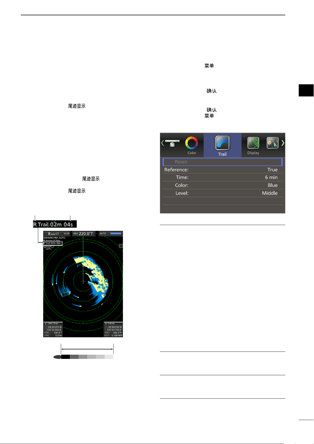
■ Trail function
Trail time
BASIC OPERATION
2
The trail function memorizes echoes continuously or
at constant intervals. This is useful for watching other
vessels’ tracks, approximate relative speed and so
on.
D Using the Trail function
1. Push [TRAILS]/[ ] to turn ON the Trail
function.
• The trail indicator and the trail interval are displayed
in the upper left of the screen.
• The trail interval counter starts to count up to the trail
time.
2. All echoes higher than the specified level at the
plotted time are memorized and displayed with
a graduated intensity together with the current
echoes.
• Echoes are displayed with minimum intensity when
“∞” is selected.
L Hold down
the trail interval counter and the plotted echoes.
3. Push [TRAILS]/[ ] to cancel the Trail
function and erase the plotted echoes.
• The trail indicator and the trail interval disappear.
Trail indicator Trail interval counter
[TRAILS]/[ ] for 1 second to reset
D Customizing the trail settings
You can customize the trail settings in the Trail menu
of the Menu screen.
1. Push [MENU]/[ ] to display the Menu screen.
2. Push [t] or [u] to select the Trail menu.
3. Push [p] or [q] to select an item.
L The selectable settings are described below.
4. Push [ENTER]/[ ] to enter the option selection
mode.
5. Push [t] or [u] to select an option.
6. Push [ENTER]/[ ] to save the setting.
7. Push [MENU]/[ ] to exit the Menu screen.
(MENU w Trail)
Reference
• True: Regardless of the movement of your
vessel, the trail of other vessels displays a
real movement over ground. Therefore, a
stopped target's trail is not displayed. The
True trail requires a heading signal and
your own vessel's position information.
• Relative: The trail of other vessels is relative to
your vessel. In this mode, other vessels’
movement and your vessel’s movement
are combined, so, Relative trail is valid if
you want to look at the relative movement
to avoid collisions. However, a stopped
target’s trail is also displayed. In that
case, it is difcult to see in some places
such as near islands.
L Regardless of this setting, the display acts as:
• The Relative trail setting when the Head-UP (H-UP)
screen is selected.
• The True trail setting when the True motion (TM)
screen is selected.
Time
Selects the trail time from 30 seconds, 1 minute, 3
minutes, 6 minutes, 15 minutes, or
Color
Selects the trail time from Blue, Yellow, Green, Red,
Orange, and White.
∞ (continuous)
1
2
3
4
5
6
7
8
9
10
11
12
13
14
15
16
17
18
19
20
21
Level
• Low: Leaves a trail between Low and High levels.
• Middle: Leaves a trail between Mid and High levels.
• High: Leaves a trail only at the High level.
12
Page 18
2
BASIC OPERATION
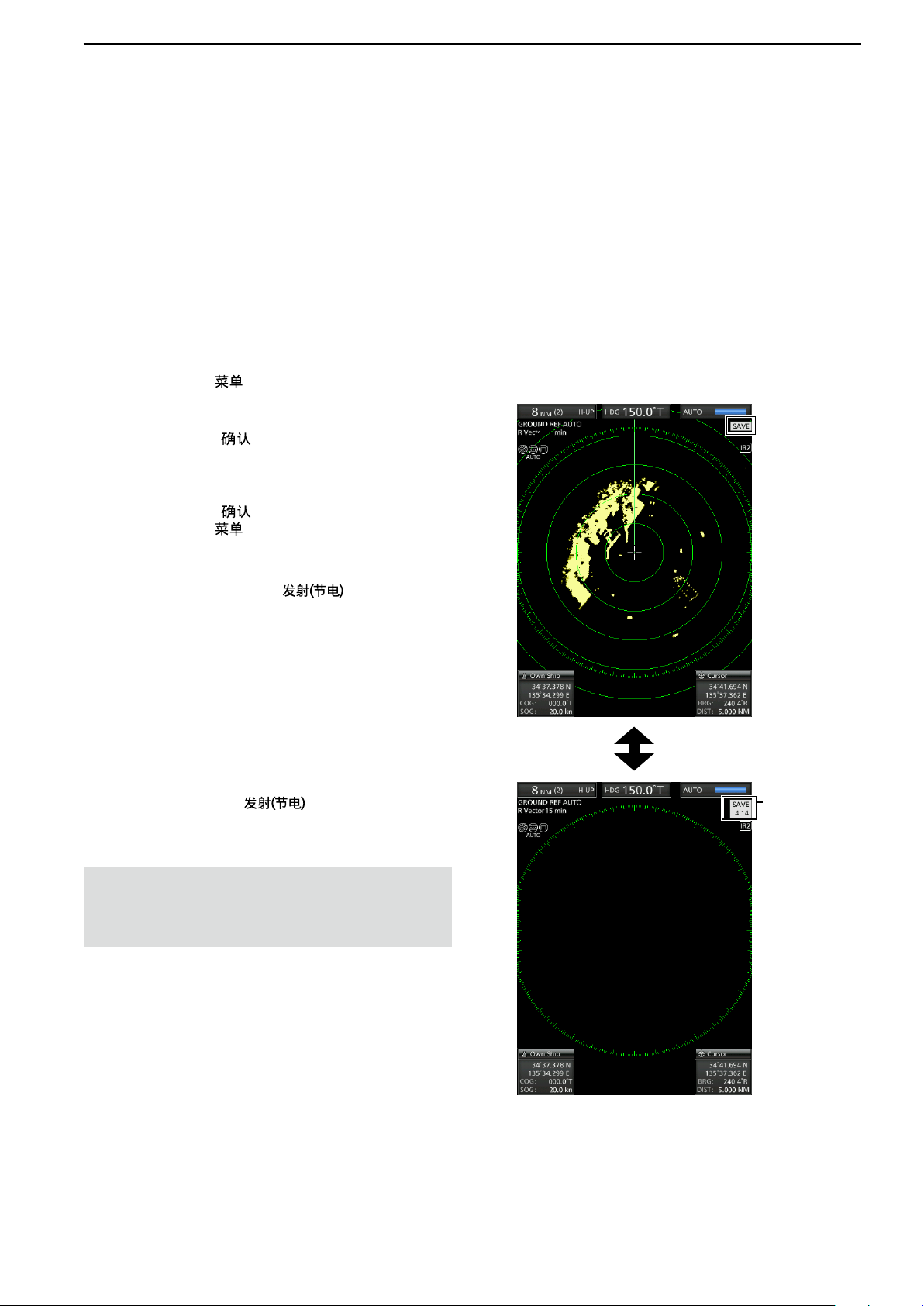
■ Power save function
The power save function conserves the vessel's
battery power by pausing the transmission. The
standby (pausing) times are selectable (rotation
number is xed to 10).
For example, when 1 minute is selected, the scanner
rotates 10 revolutions, then stops for 1 minute, and
then repeats this sequence while the power save
mode is activated.
D Setting the scanning standby time
1. Push [MENU]/[ ]
2. Push [t] or [u] to select the System menu.
3. Push [p] or [q] to select the “Save Time” item.
4. Push [ENTER]/[ ] to enter the option selection
mode.
5. Push [t] or [u] to select the standby time.
L 1, 6, 15, and 30 minutes are selectable.
6. Push [ENTER]/[ ] to save the setting.
7. Push [MENU]/[ ] to exit the Menu screen.
(MENU w System w Save Time)
D Entering the power saving mode
1. Hold down [TX (SAVE)]/[ ] for 1 second
to enter the power save mode.
• The “SAVE” indicator is displayed in the upper right of
the screen.
2. After the scanning rotations are finished,
transmission and rotation are suspended until the
selected standby time elapses.
• “SAVE” and standby time are displayed in the upper
right of the screen and the standby time is counted
down.
• After the selected standby time elapses, transmission
and rotation restart.
3. Push [TX (SAVE)]/[ ] to cancel the power
save function.
• The save indicator turns OFF.
NOTE: You can save more power by using the
Power save function with the Alarm function. In this
case, the LCD display is turned OFF until an object
enters the programmed alarm zone. (p. 21)
Counts down
the standby
time
13
Scan and STBY modes alternate
Page 19
■ Ship speed indication
BASIC OPERATION
2
When the ship speed data in NMEA 0183 format is
applied, the radar can display the ship speed.
1. Push [MENU]/[ ].
2. Push [t] or [u] to select the Initial menu.
3. Push [p] or [q] to select the “Speed Unit” item.
4. Push [ENTER]/[ ] to enter the option selection
mode.
5. Push [t] or [u] to select the desired speed unit.
L knot (kn) or kilometers/hour (km/h) is selectable.
6. Push [ENTER]/[ ] to save the setting.
7. Push [MENU]/[ ] to exit the Menu screen.
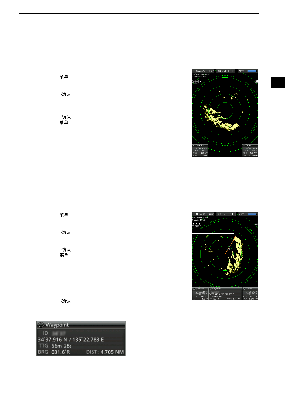
■ Waypoint indication
When waypoint data received from navigation
equipment in NMEA 0183 format is applied, the radar
can display the waypoint.
To display the waypoint marker, bearing data and
position data are required. (p. 53)
(MENU w Initial w Speed Unit)
Ship Speed
Indicator
(MENU w Display w WPT Display)
1
2
3
4
5
6
7
8
9
10
11
D Displaying the waypoint marker
1. Push [MENU]/[ ].
2. Push [t] or [u] to select the Display menu.
3. Push [p] or [q] to select the “WPT Display” item.
4. Push [ENTER]/[ ] to enter the option selection
mode.
5. Push [t] or [u] to turn the setting ON or OFF.
6. Push [ENTER]/[ ] to save the setting.
7. Push [MENU]/[ ] to exit the Menu screen.
D Waypoint information
1. Move the cross-line cursor on the waypoint mark
or line.
2. Push [ENTER]/[ ] to display the information.
• The target identication (ID), position, Time to go
(TTG), bearing (BRG), and distance (DIST) are
displayed in the information box.
Waypoint marker
12
13
14
15
16
17
18
19
20
21
14
Page 20
2
BASIC OPERATION
■ Bearing settings
The radar bearing interface accepts NMEA, N+1,
AUX, or COG data format and the bearing can use a
magnetic or true north type. When a true north type
bearing is used, the variation from magnetic north
can be adjusted on 0.1˚ steps.
D Setting the bearing input
1. Push [MENU]/[ ].
2. Push [t] or [u] to select the Initial menu.
3. Push [p] or [q] to select the “Bearing Input ”
item.
4. Push [ENTER]/[ ] to enter the option selection
mode.
5. Push [t] or [u] to select the bearing data source.
L NMEA, N+1, AUX, GPS, or GPS-L is selectable.
L GPS and GPS-L uses the COG (Course Over
the Ground) data as the bearing. However, if
the vessel's speed is less than 3 knots, direction
accuracy falls. Moreover, the position accuracy or
the current actual course may vary, therefore the
radar may display incorrect direction.
6. Push [ENTER]/[ ] to save the setting.
7. Push [MENU]/[ ] to exit the Menu screen.
(MENU w System w Bearing Mode)
T: True north
M: Magnetic north
D Setting the bearing type
1. Push [MENU]/[ ].
2. Push [t] or [u] to select the System menu.
3. Push [p] or [q] to select the “Bearing Mode”
item.
4. Push [ENTER]/[ ] to enter the option selection
mode.
5. Push [t] or [u] to select the Bearing mode.
L True and Magnetic north type are selectable.
L All displayed bearing readouts show the selected
bearing type.
6. Push [ENTER]/[ ] to save the setting.
7. Push [MENU]/[ ] to exit the Menu screen.
15
Page 21
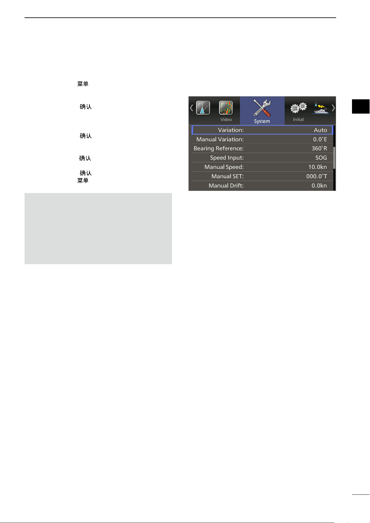
D Setting the magnetic variation
1. Push [MENU]/[ ].
2. Push [t] or [u] to select the System menu.
3. Push [p] or [q] to select the “Variation” item.
4. Push [ENTER]/[ ] to enter the option selection
mode.
5. Push [t] or [u] to select the bearing variation.
L “Auto”* and “Manual” are selectable.
6. Push [ENTER]/[ ] to save the setting.
7. When the “Manual” option is selected in step 4,
push [q] to select the “Manual Variation,” then
push [ENTER]/[ ].
8. Push [p] or [q] to set the bearing variation.
9. Push [ENTER]/[ ] to save the setting.
10. Push [MENU]/[ ] to exit the Menu screen.
BASIC OPERATION
(MENU w System w Variation)
2
1
2
3
4
5
6
7
NOTE:
• NMEA data is required for the Auto variation. NEVER
select “Auto” without NMEA data or incorrect variation
data may be entered.
• Until an effective variation is received, use 0° for
difference between true North and magnetic North. After
an effective variation is received, use the last data for
the difference. The MR-1010RII memorize the data until
you turn OFF the power.
8
9
10
11
12
13
14
15
16
17
18
19
16
20
21
Page 22
3
DISTANCE AND DIRECTION MEASUREMENTS
■ Distance measurement
Various ways to measure the distance are provided with this radar.
L You can select
Fixed range ring
Parallel index lines
Variable range marker 1
Variable range marker 2
a distance unit from nautical miles (NM), or kilometers (kn) in the Initial menu (p. 45).
TYPE DESCRIPTION
Displays xed rings.
(RING)
(PI)
(VRM1)
(VRM2)
Suitable for rough estimations from your own vessel to any target.
Selectable from two types of range rings.
Displays six parallel index lines.
Suitable for rough estimations from your own vessel to any target.
Displays a variable range marker and activated by [p] or [q] for the range marker
selector. Suitable for accurate measurements from your own vessel to a target.
Normally functions the same as VRM1. When the VRM1 and EBL1 selects a
target, the center of VRM2 appears at the intersection point. Suitable for accurate
measurements from target to target.
D Using the xed rings
(MENU w Initial w Range Ring)
1. Push [MENU]/[ ].
2. Push [t] or [u] to select the Initial menu.
3. Push [p] or [q]Select the Range Ring item.
4. Push [ENTER]/[ ] to enter the option selection
mode.
5. Push [t] or [u] to select Ring 1 or Ring 2.
6. Push [ENTER]/[ ] to save the setting.
7. Push [MENU]/[ ] to exit the Menu screen.
• Difference between Ring1 and Ring2 (NM)
Range
(NM)
1.5 0.5 0.25 3 6
3 1 0.5 3 6
6 2 1 3 6
12 3 2 4 6
24 6 4 4 6
Ring (NM): Distance between the rings
• Difference between Ring1 and Ring2 (km)
Range
(km)
1/2 0.125 0.25 4 2
1.5 0.5 0.25 3 6
3 1 0.5 3 6
6 2 1 3 6
Ring (km): Distance between the rings
Ring (NM) Number of rings
Ring1 Ring2 Ring1 Ring2
Ring (km) Number of rings
Ring1 Ring2 Ring1 Ring2
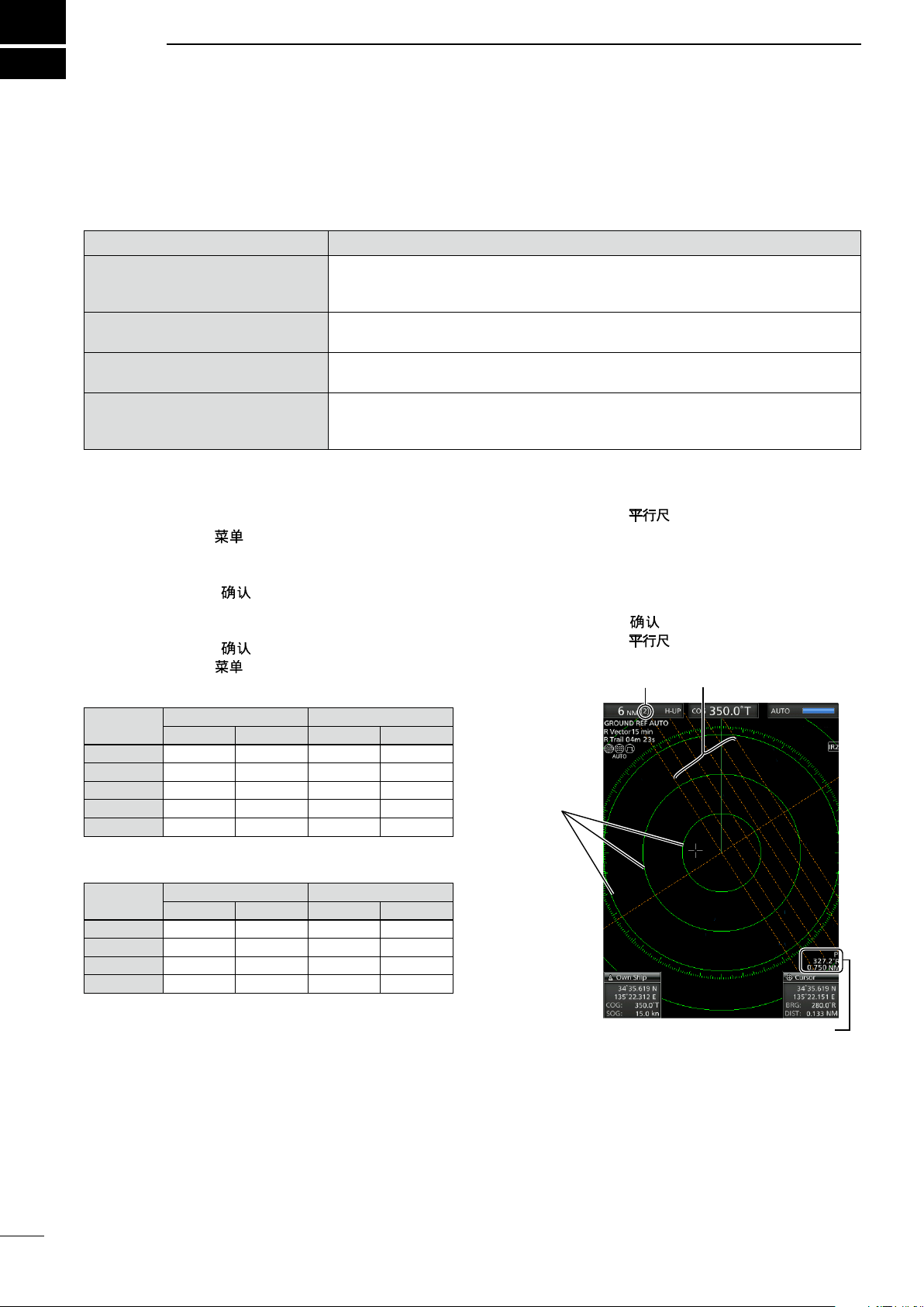
D Using the Parallel index lines
1. Hold down [PI]/[ ] for 1 second.
• The crossed lines are displayed.
2. Push [p] or [q] to increase or decrease the
range of lines, and [t] or [u] to rotate the lines.
• The direction of the parallel index lines and the line
interval are displayed on the lower right of the screen.
3. Push [ENTER]/[ ] to set lines.
4. Hold down [PI]/[ ] for 1 second to clear the
parallel index lines.
Ring range
Fixed rings
Parallel index lines
Parallel index lines readout
17
Page 23

D Using the variable range marker
DISTANCE AND DIRECTION MEASUREMENTS
3
1. Push [EBL1 (VRM1)]/[
the VRM1 and EBL1, then push [p] or [q] to set
the marker.
• The range between the vessel and the target is
indicated in the EBL/VRM1 readout.
2. Push [ENTER]/[ ] to set the EBL/VRM1
setting.
3. Push [EBL2 (VRM2)]/[ ] to display
the VRM2 and EBL2, then push [p] or [q] to set
the marker.
• The range between the vessel and the target is
indicated in the EBL/VRM2 readout.
• When VRM1 and EBL1 are displayed, the center of
VRM2 appears at the intersection point of VRM1 and
EBL1.
] to display
■ Bearing and Distance measurement
This radar has two Electronic Bearing Lines (EBL)
to indicate the target direction from your vessel or a
target.
D Using both the EBL and VRM
1. Move the cross-line cursor onto the desired
target.
2. Push [EBL1 (VRM1)]/[ ] to display
the EBL1 and VRM1.
• Push [t] or [u] to rotate the Electronic Bearing Line.
• Push [p] or [q] to increase or decrease the Variable
Range Marker’s ring size.
• The EBL/VRM1 readout indicates the target bearing
and distance.
• The EBL readouts indicate the target bearing.
• The indication may differ, depending on the setting in
the “Bearing Reference” item of the System menu (p.
12).
• 0 to 360°R: Relative direction, when “360°R” is
selected in the “Bearing Reference”
item.
• P/S 0 to 180°: Bow direction, when “PT/SB” is
selected in the “Bearing Reference”
item.
• 0 to 360°T*: True or magnetic bearing, when
selecting “True” in the “Bearing
Reference” item.
*Bearing data is required. (p. 53)
3. Push [ENTER]/[ ] to set the EBL/VRM1
setting.
4. Move the cross-line cursor onto the desired
target.
5. Hold down [EBL1 (VRM1)]/
1 second to move the EBL1 and VRM1 to the
cur sor.
L Hold down [EBL1 (VRM1)]/
second again to move the EBL1 and VRM1 to the
original place.
6. Push [EBL1 (VRM1)]/[ ] to clear the
EBL1 and VRM1.
L Cursor remains on the display.
[ ]
[ ]
for
for 1
4. Push [ENTER]/[ ] to set the EBL/VRM2
setting.
5. Push [EBL1 (VRM1)]/[ ] to clear the
EBL1 and VRM1.
6. Push [EBL2 (VRM2)]/[ ] to clear the
EBL2 and VRM2.
EBL1
VRM1
EBL/VRM1 readout
EBL1
VRM1
EBL1/VRM1 readout
1
2
3
4
5
6
7
8
9
10
11
12
13
14
15
16
17
18
19
20
21
18
Page 24

3
DISTANCE AND DIRECTION MEASUREMENTS
■ Advanced measurements
Using both Electronic Bearing Lines (EBL) and both Variable Range Markers (VRM), the following advanced
measurements can be made.
D Measuring the distance and direction between two targets
1. Move the cursor onto the desired target.
2. Push [EBL1 (VRM1)]/[ ] to display
the EBL1 and VRM1.
L Push [t] or [u] to rotate the Electronic Bearing Line.
L Push [p] or [q] to increase or decrease the Variable
Range Marker ring size.
3. Push [ENTER]/[ ] to set the VRM/EBL1
setting.
4. Push [EBL2 (VRM2)]/
[ ]
to display
the EBL2 and VRM2.
• The intersection of the EBL1 and VRM1 becomes the
center of the EBL2 and VRM2.
5. Push [p], [q], [t], or [u] to move the cursor onto
the other target.
L Push [t] or [u] to rotate the Electronic Bearing Line.
L Push [p] or [q] to increase or decrease the Variable
Range Marker ring size.
6. The VRM2 readout displays the distance
between the two targets. The EBL2 readout
displays the direction from one target to the other.
VRM1
EBL1
VRM2
EBL2
19
D Measuring the relative speed and course of a target
1. Push [TRAILS]/[
function, and then the trail extends until it reaches
to the preset trail time. (p. 12)
• The trail icon and trail interval are displayed in the
upper left of the screen.
2. Push [EBL1 (VRM1)]/[ ] to display
the EBL1 and VRM1, and then set the VRM1 and
EBL1 to a previously plotted target.
L Push [t] or [u] to rotate the Electronic Bearing Line.
L Push [p] or [q] to increase or decrease the Variable
Range Marker ring size.
3. Push [ENTER]/[ ] to set the VRM/EBL1
setting.
4. Push [EBL2 (VRM2)]/
the EBL2 and VRM2, and then set the VRM2 and
EBL2 to the current plotted position of the same
target.
• The intersection of the EBL1 and VRM1 becomes the
center of the EBL2 and VRM2.
5. The VRM2 is a measure of target movement that
can be converted into relative target speed.
L For example, when a 6 minute trail time is selected,
multiplying the distance by ten gives the relative
average speed of the target.
L If your vessel is stationary during the plotting time,
the converted speed and direction become absolute.
L The converted speed unit is knots, kilometers or
miles, depending on the Distance Unit in the Initial
menu.
6. The EBL2 displays the course direction of the
target.
] to turn ON the Trail
[ ]
to display
VRM1
EBL1
EBL2
VRM2
Page 25

DISTANCE AND DIRECTION MEASUREMENTS
D Measuring the distance and course from a waypoint
1. Display a waypoint as described on page 14.
2. Push [EBL1 (VRM1)]/[
the EBL1 and VRM1, and then set the VRM1 and
EBL1 to the waypoint.
• Push [t] or [u] to rotate the Electronic Bearing Line.
L Push [p] or [q] to increase or decrease the Variable
Range Marker ring size.
3. Push [ENTER]/[ ] to set the VRM/EBL1
setting.
4. Push [EBL2 (VRM2)]/
the EBL2 and VRM2, and then set the VRM2
and EBL2 to a target point, for example a next
waypoint.
• The intersection of the EBL1 and VRM1 becomes the
center of the EBL2 and VRM2.
5. The VRM2 displays the distance to the target
from the first waypoint.
• The distance unit can be selected as nautical miles
(NM) or kilometers (km) in the Initial menu.
6. The EBL2 readout displays the direction to the
target from the first waypoint.
[ ]
] to display
EBL2
VRM2
to display
3
EBL1
VRM1
1
2
3
4
5
6
7
8
9
10
11
12
13
14
15
16
17
18
19
20
21
20
Page 26

4
The unit has an alarm function to protect your vessel from collisions. If other vessels, islands, or other
obstructions come into the preset alarm zone, the function alerts you with an alarm. You can set the desired
range and bearing for up to two alarm zones. While the alarm function is activated, the power save function turns
off the LCD screen until an alarm is given, to conserve the power.
ALARM FUNCTION
■ Setting the Alarm zone
D Setting and using the alarm function
1. Push [+] or [–] to select a desired range.
2. Move the cross-line cursor to the starting point of
the alarm zone.
3. Push [ALM1/2]/[ 1/2] several times to turn ON
the desired functions, Alarm 1 or Alarm 2.
• The Alarm icon ( ) on the upper right of the screen
and the preset alarm zone(s) is displayed. (Fig. 1)
4. Hold down [ALM1/2]/[ 1/2] for 1 second to
enter the alarm zone setting.
• The starting zone is displayed on the screen. (Fig. 1)
5. Push [t] or [u] to adjust an angle and push [p]
or [q] to set the distance of the alarm zone.
• The selected alarm zone is displayed.
6. Push [ALM1/2]/[ 1/2] to set the alarm zone
and activate the alarm function.
• The Alarm icon is displayed.
• The selected alarm zone remains.
7. If a target comes into or goes out of the alarm
zone, an alarm sounds.
L Push [CLEAR]/[ ] to stop the alarm.
L Push [ALM1/2]/[
and function.
8. To deactivate the alarm function, push [ALM1/2]/
[ 1/2] several times.
• The Alarm icon
9. To activate the alarm function again with the
same programmed zone, push [ALM1/2]/
[ 1/2].
• “ ” and the preset alarm zone is displayed. (Fig. 2)
1/2] to cancel the alarm signal
and alarm zone disappears.
Use cursor pad to adjust the alarm
zone, then push [ALM1/2]/[
set it.
1/2] to
Alarm icon
Fig. 1
21
NOTE: If “ ” is displayed, the alarm function is
invalid because the range is too small. In that case,
push [+] one or more times until the alarm icon
returns to
“ .”
D Entering the power save mode
The Alarm function is also available when the
MR-1010RII is in the power save mode.
z Hold down [TX (SAVE)]/[ ] for 1 second
while the Alarm function is ON.
• The power save mode is activated and the display
turns OFF.
L When a target comes into the alarm zone, an alarm
sounds, the display turns ON, and the power save
mode is cancelled.
Fig. 2
Page 27

Alarm sounds when the target
comes into the zone.
Alarm zone
Target (other ship, and so on)
■ Setting Zone alarm type
ALARM FUNCTION
4
A zone alarm sounds when the target comes into the
zone, or when the target goes out of the zone. (p. 13)
1. Push [MENU]/[ ], and then push [t] or [u] to
select the System menu.
2. Push [p] or [q] to select the “Zone Alarm1” or
“Zone Alarm2” item.
3. Push [ENTER]/[ ] to enter the option selection
mode.
4. Push [t] or [u] to select IN or OUT.
• IN: Alarm sounds when the target comes into the
zone.
• OUT: Alarm sounds when the target goes out of the
zone.
5. Push [ENTER]/[ ] to save the setting.
6. Push [MENU]/[ ] to exit the Menu screen.
(MENU w System w Zone Alarm1)
(MENU w System w Zone Alarm2)
1
2
3
4
5
6
7
8
9
10
11
12
13
14
15
16
17
18
19
20
21
22
Page 28

5
The simplied Automatic Radar Plotting Aids (ARPA) function is designed to help prevent a collision with other
vessels or landmasses.
The radar automatically acquires and plots other vessels and landmasses that are in the set watch area. It
automatically calculates the closest point of approach (CPA), and the time to closest point of approach (TCPA)
limit of your vessel and the targets, and sounds an alarm if there is a danger of colliding with them.
ARPA Features
• Only targets in the 0.25 to 16 NM range that are displayed with a high luminosity (strong return signal) can be
selected as ARPA targets.
• Up to 10 targets can be acquired and plotted on the screen, including up to 5 automatically acquired targets
(when the Auto Acquire function (p.25) is turned ON in the Menu screen).
• Plot positions are identied by an approved symbol mark (p. 24) and associated plot number.
• The target and vector line will move across the screen at the rate and direction dened by the calculated true or
relative course and speed.
• The vector line is displayed on the target.
THE SIMPLIFIED ARPA OPERATION
■ ARPA operation
D Operation
Select a target on the screen that you want to track.
1. Move the cross-line cursor onto a desired target.
2. Push [ACQ]/[ ] to set the target for tracking.
• A dotted circle symbol is displayed on the cursor.
• After 1 minute progressing time has passed, the circle
changes to a solid circle with a dotted vector line, the
number of the target is displayed beside the icon, and
tracking operation starts.
• When the target disappears, a red cross blinks on the
target, and then the mark disappears after 1 minute.
• When a target advances within the CPA and TCPA
limits, the mark changes its color to red, blinks, and
sounds an alarm. To cancel the alarm, push [CLEAR]/
[
].
3. To display a target information, move the crossline cursor onto the target, and then push
[ENTER]/[ ].
• The corners of a square is displayed on the selected
target.
• The target identication number, position, course
(CRS), speed (SPD), CPA, TCPA, bearing (BRG), and
distance (DIST) are displayed.
Target
ARPA
icon
23
4. To release the target, move the cursor onto the
target, then hold down [CLEAR]/[ ] for 1
second.
Page 29

Vector
Current position
Vector time
Target’s predicted
positon
■ Descriptions of ARPA targets
D The status icons
The followings are the status icons for APRA targets.
Status Description
Focused target is displayed with the orange colored circle
THE SIMPLIFIED ARPA OPERATION
5
1
2
Selected target is displayed with corners of the square
Selected, started to acquire automatically or manually.
Acquired target
Approximately 1 minute after the acquirement is started, the dotted circle icon changes to a
circle, and the vector of the vessel is displayed.
Target with a number
5
Displayed when the No. Display setting in the ARPA menu in the Menu screen is set to
“Select”or “all”.
CPA/TCPA alarm mark.
The target is close to within a minimum range and time.
• Alarm sounds and red colored mark blinks until acquiring the target.
Push [ACQ]/[
Indicates the tracking of a target is lost.
• Alarm sounds, red cross blinks, and “ARPA target lost” is displayed.
Push any key to cancel the alarm.
] to acquire the target, or push [CLEAR]/[ ] to cancel the alarm.
D Course and speed vector
The vector indicates the target’s predicted, true or
relative course and speed.
• The vector time may change, depending on the setting in
the “Vector Time” item of the Target menu (p. 41).
• The tip of the vector shows the target’s predicted position
after the time selected in the “Vector Time” item of the
Target menu (p.41).
D Plots (ARPA)
The plot displays the target’s past positions as 5 dots,
during each specied tracking interval.
• The target track interval may change, depending on the
setting in the “Track Interval” item of the Target menu.
(p. 41)
Plots Status
Target is going straight
3
4
5
6
7
8
9
10
11
12
13
14
15
16
17
Target is turning right
Target is reducing speed (dots are
closer together behind the target)
Target is increasing speed (dots
are father apart behind the target)
18
19
20
21
24
Page 30

5
THE SIMPLIFIED ARPA OPERATION
■ ARPA settings
You can customize the ARPA settings in the ARPA
menu of the Menu screen.
1. Push [MENU]/[ ].
2. Push [t] or [u] to select the ARPA menu.
3. Push [p] or [q] to select the item.
4. Push [ENTER]/[ ] to enter the option selection
mode.
5. Push [t] or [u] to select an option.
6. Push [ENTER]/[ ] to save the setting.
7. Push [MENU]/[ ] to exit the Menu screen.
(MENU w ARPA )
All Clear Targets
Releases all of the ARPA targets at the same time.
1. Push [ENTER]/[
2. Push [t] to select “OK”.
3. Push [ENTER]/[ ] again to release all ARPA
targets.
• The “All Clear Target” item is grayed out.
].
■ Related settings
You can change the target settings for ARPA operation.
The settings of the Target menu are commonly used for
the ARPA and AIS operations. See page 41 for the Target
menu details.
The Target menu items and their default settings are as
follows.
• Vector Mode: True
• Vector Time: 6 min
• Track Interval: 1 min
• CPA* Limit: 1.0 NM
• TCPA* Limit: 1 min
• CPA/TCPA Alarm: ON
* CPA/TCPA: Closest Point of Approach and Time to
Closest Point of Approach limits are set to give a warning
when a target or targets enter those limits around your
own vessel.
Function (Default: ON)
• OFF: Turns OFF the ARPA (Automatic Radar
Plotting Aid) function.
• ON: Turns ON the ARPA function.
Auto Acquire (Default: OFF)
Sets whether the MR-1010RII automatically acquires
targets or not.
• OFF: Does not automatically acquire a target.
• ON: Automatically acquires up to 5 targets.
Track (Default: OFF)
The plot displays the target’s past positions as 5 dots,
during each specied tracking interval.
You can specify the track interval in the “Track
Interval” item of the Target menu.
• OFF: Turns OFF the Track display function.
• ON: Turns ON the Track display function.
No. Display (Default: Select)
Select the target identication number type that
appears at the right side of the mark.
• OFF: Does not display any mark number.
• Select: Displays only the selected mark number.
• All: Displays all mark numbers.
25
Page 31

■ About AIS
AIS RECEIVER
6
The Automatic Identication System (AIS) is primarily used
for collision-risk management and navigation safety. It
automatically transmits and receives vessel information,
such as the vessel name, MMSI code, vessel type, position
data, speed, course, destination and more. Information
is exchanged among the vessels and/or base stations on
the VHF maritime mobile band. The information helps to
identify other nearby vessels or stations by displaying the
received data on a plotter or a radar screen.
There are 7 types of AIS stations, vessels, base stations,
Search and Rescue (SAR), Aids to Navigation (AtoN),
Search and Rescue Transmitter (AIS-SART), Man
OverBoard (MOB), and Emergency Position Indicating
Radio Beacon-AIS (EPIRB-AIS).
Also, there are 2 classes of AIS units, which are installed on
vessels, Class A and Class B.
■ AIS operation
D Displaying AIS information
Select a target whose information you want to display
on the screen.
Turn ON the AIS display and set its settings.
(pp. 29–31)
1. Move the cross-line cursor onto a desired target.
2. Push [ENTER]/[ ] to select the target.
• The corners of a square appear on the selected target
and the target information appear in the AIS information
box.
• AIS Class, MMSI number, Vessel name, Course
(CRS), Speed (SPD), CPA, TCPA, bearing (BRG),
and distance (DIST) are displayed.
InformationL
• If several targets are overlapped on the screen, push
[ENTER]/[
• When the target disappears, red crosses blink on the
target, and then the mark disappears after 6 minutes
and 40 seconds.
] to sequentially select a target.
Other vessel
Other vessel
(Class B AIS)
Vessel Information
Your vessel
(Class A AIS)
Displaying the AIS Details
1. Move the cross-line cursor onto a desired target.
2. Hold down [ENTER]/[ ] for 1 second.
• The AIS details is displayed in the message box.
Push [CLEAR]/[
Activating the sleeping target manually
1. Select a sleeping target, then holding down
[ENTER]/[ ] for 1 second to display the AIS
details.
2. Push [ENTER]/[ ] to change the selected
target to activated.
3. Push [CLEAR]/[ ] to close the AIS details
message box.
Changing the activated target to sleeping
z Move the cross-line cursor to an activated target,
then hold down [CLEAR]/[ ] for 1 second to
change the selected target to sleeping.
(Class A AIS)
Base Station
] to close the message box.
D Warning message by AIS receiver
When a target advances within the CPA and TCPA
limits, mark changes its color to red and blinks. A
warning message is displayed, and an alarm sounds.
Push [CLEAR]/[ ] to cancel the alarm.
1
2
3
4
5
6
7
8
9
10
11
12
13
14
15
16
17
18
19
20
21
26
Page 32

6
AIS RECEIVER
■ Description of the AIS display
e
w
q
D AIS target icons
The AIS targets are displayed with an icon described
below, depending on the type of the target.
Icon Description
Vessel (p. 28)
The tip of the target triangle automatically points
in the direction it’s heading.
Vessel (p. 28)
The vessel that the CPA and TCPA could not be
calculated.
Base Station
Search and Rescue (SAR)
Search and Rescue (SAR) craft
Aids to Navigation (AtoN)
r
q AIS indicator:
Displayed when a valid VDM sentence is input
from the [NMEA1] (AIS) port.
The indicator disappears if the AIS signal is not
received for 6 minutes.
w Selected AIS target:
Four corners of a square are displayed when a
target is selected. The details of the selected AIS
target is displayed in the AIS information box (r).
e AIS target:
The icons in the table to the top left are displayed
as AIS targets.
r AIS information box
Displays the selected AIS information.
AIS Class, MMSI number, Vessel name, Course
(CRS), Speed (SPD), CPA, TCPA, bearing
(BRG), and distance (DIST) are displayed.
L Your vessel icon is displayed in the center of the
standby screen when a valid VDM sentence is
input from the [NMEA1] (AIS) port.
L The AIS target icons are displayed when “AIS” is
selected in the “STBY Mode” item of the System
menu (p. 31).
Virtual Aids to Navigation (Virtual AtoN)
Search and Rescue Transponder (SART), MAN
OVERBOARD (MOB), or Emergency Position
Indicate Radio Beacon (EPIRB)
27
If more than the specied AIS signals are received,
“R AIS Data is Full” is displayed.
The number of AIS signals are specied in the
“Number of AIS” item of the AIS menu.
Page 33

AIS RECEIVER
6
D Status of the vessel icon
There are 5 kinds of target vessel status.
Sleeping target:
The AIS signal has been updated (received),
but the distance from your vessel is far, or you
set it as ‘sleeping.’ The target is displayed as
just a triangle without a heading or vector line.
Activated target:
The target is displayed with the heading line,
SOG (Speed Over Ground), COG (Course
Over Ground) vector and ROT (Rate of Turn).
SOG (Speed Over Ground) and
COG (Course Over Ground) vector
ROT (Rate of Turn)
Heading line
If there is no heading data, the line points
in the direction of COG.
Dangerous target:
Selected target:
The target’s information is displayed in the
Lost target*:
When the AIS signal has not been updated
If the AIS signal has still not been updated
* A vessel is regarded as a “Lost target” after a
Even if the target’s status is sleeping or
activated, when it enters your CPA and TCPA
limit settings, the target is displayed with a
thick line and changes its color to red.
data area.
(received) for a specic time period, the target
triangle is marked with a red cross.
(received) for 6 minutes and 40 seconds, the
target icon disappears.
specied period of time has passed since the
vessel last transmitted data. (p.29)
D Plots (AIS)
The plot displays the activated target, SAR, SART,
MOB, or EPIRB’s past positions as 5 dots, during
each specied tracking interval.
• The target track may change, depending on the setting in
the “Track Interval” item of the Target menu. (p. 31)
Plots Status
Target is going straight
Target is turning right
Target is reducing speed
Target is increasing speed
1
2
3
4
5
6
7
8
9
10
11
12
13
14
15
16
17
18
19
20
21
28
28
Page 34

6
AIS RECEIVER
■ AIS settings
You can customize the AIS function in the Menu
screen .
1. Push [MENU]/[
select the AIS menu.
2. Push [p] or [q] to select the item.
3. Push [ENTER]/[ ] to enter the option selection
mode.
4. Push [p], [q], [t], or [u] to select an option.
5. Push [ENTER]/[ ] to save the setting.
6. Push [MENU]/[ ] to exit the Menu screen.
D AIS menu
(MENU w AIS)
], and then push [t] or [u] to
Auto Activate (Default: ON)
The Auto Activate function automatically turns the
sleeping AIS target into an activated target when the
AIS target is at the specied distance or angle.
You can specify the distance or angle in the next two
items.
• OFF: Turn OFF the Auto Activate function.
• ON: Turn ON the Auto Activate function.
Auto Activate - Distance (Default: 1.0NM)
Sets the distance from your vessel to between 0.1
and 10.0 NM, to automatically turn the sleeping AIS
target into an activated target.
Auto Activate - Angle (Default: ±180°)
Sets the angle from your vessel between 5 to 180°
to automatically turn the sleeping AIS target into an
activated target.
Display (Default: ON)
Turns the AIS Display function ON or OFF when the
MR-1010RII is in Trasmitting (TX) mode.
• OFF: Turn OFF the AIS display function.
• ON: Turn ON the AIS display function.
Track (Default: OFF)
The plot displays the AIS target’s past positions as 5
dots, during each specied tracking interval.
You can specify the track interval in the “Track
Interval” item of the Target menu.
• OFF: Turn OFF the Track display function.
• ON: Turn ON the Track display function.
Name Display (Default: OFF)
Selects the AIS target display type.
• OFF: Does not display any name or
number of the target.
• Select: Displays the vessel name of the
selected target.
• Active: Displays all active target numbers.
New Target Warning (Default: OFF)
Sets whether the MR-1010RII gives a warning when
the Auto Activate function automatically turns the
sleeping AIS target into an activated target, or not.
• OFF: Does not give a warning when the Auto
Activate function activates the target.
• ON: Gives a warning when the Auto Activate
function activates the target.
Number of AIS (Default: 100)
Selects the maximum number of AIS targets that can
be displayed on the screen to between 10 and 100 in
1 target steps.
Slow Warn (Default: ON)
The AIS unit calculated COG (Course Over Ground)
data of a vessel that is at anchor or drifting is
unreliable, and therefore the CPA (Closest Point of
Approach) and TCPA (Time to CPA) data may not
be correctly calculated. If a vessel is anchored in
your alarm zone, the unreliable data can cause the
collision alarm to sound many times, even if there is
no real danger. To prevent this, when the anchored
vessel’s SOG (Speed Over Ground) is less than
this set value, the Slow Warn function assumes that
vessel’s COG is xed towards your vessel and an
alarm will sound.
• OFF: Turn OFF the Slow Warn function.
• ON: Turn ON the Slow Warn function.
Slow Warn Speed (Default: 0.1kn)
Selects the vessel’s speed to between 0.1 and 5.0
kn, in 0.1 kn steps.
29
Page 35

Erase Lost Target (Default: ON)
Erases all of the Lost targets at the same time.
When there are no lost targets, this setting grays out.
1. Push [ENTER]/[
2. Push [t] to select <OK>.
3. Push [ENTER]/[ ] again to clear all of the Lost
targets on the screen.
].
AIS RECEIVER
6
1
2
3
About “Lost Target”: A vessel is regarded as a “Lost
target” after a specied period of time has passed
since the vessel last transmitted data, as described
below.
The “Lost target” icon disappears from the screen
6 minutes and 40 seconds after the vessel was
regarded as a “Lost target.”
The criteria to become a Lost target
• Class A/B
Nominal
Vessel type
Vessel is at anchor or moored
Class A
1
Class B
Vessel is at anchor or moored and moving
2
faster than 3 knot
Class A
3
Class B
Class A
4
Class B
5 Vessel is moving between 14 and 23 knots
Vessel is moving between 14 and 23 knots
6
while changing course
7 Vessel is moving faster than 23 knots
Vessel is moving faster than 23 knots
8
while changing course
*1 AIS Class B does not provide information about the navigation status, anchored or moored.
*2 CS: Carrier-sense, *3 SO: Self organized, *4 N/A: Not available
• Others
Category
SAR 10 sec. 60 sec.
and not moving faster than 3
knots
Vessel is
2 knots
Vessel is moving between 0 and
14 knots
Vessel is moving between 2 and
14 knots
Vessel is moving between 0 and
14 knots while changing course
Vessel is moving between 2 and
14 knots while changing course
not moving faster than
Nominal reporting
interval
maximum interval
reporting
interval Class
3 min. 18 min. — — — —
10 sec. 60 sec. N/A*
10 sec. 60 sec. — — — —
1
⁄
3
6 sec. 36 sec.
2 sec. 36 sec.
2 sec. 30 sec.
2 sec. 30 sec.
Lost target
A
— — 3 min. 3 min. 18 min. 18 min.
— —
sec. 60 sec. — — — —
3
— —
Lost target
maximum
interval Class A
Nominal reporting
interval Class B *
2
CS *
30 sec. 30 sec. 180 sec. 180 sec.
30 sec. 30 sec. 180 sec. 180 sec.
30 sec. 15 sec. 180 sec. 90 sec.
30 sec. 15 sec. 180 sec. 90 sec.
30 sec. 5 sec. 180 sec. 30 sec.
30 sec. 5 sec. 180 sec. 30 sec.
SO *
4
Lost target maximum
1
interval Class B *
3
CS *
2
N/A*
SO *
4
4
5
6
7
8
1
3
9
10
11
12
13
14
15
16
17
18
19
20
21
Base station 10 sec. 60 sec.
AtoN 3 min. 18 min.
30
Page 36

6
Safety Message (Default: ON)
Sets whether the MR-1010RII displays the message
when a safety message is received.
• OFF: Turns OFF the Safety Message function.
• ON: Turns ON the Safety Message function.
Favorite AIS (Default: ON)
Sets whether the MR-1010RII noties that the
Specied MMSI target gets into the specied range
from your vessel, or not.
• OFF: Turns OFF the Favorite AIS function.
• ON: Turns ON the Favorite AIS function.
Favorite AIS Range (Default: 8.0NM)
Sets the Favorite AIS display range to between 0.1
and 36.0 NM, in 0.1 NM steps.
Favorite AIS Target1 / 2 / 3
Enters MMSI numbers of up to 3 vessels as your
favorite AIS targets.
AIS RECEIVER
■ AIS Settings (Continued)
■ Related settings
D Target menu
You can change the target settings for the AIS
operation. The settings of the Target menu are
commonly used for the ARPA and AIS operations.
See page 7 for the Target menu details.
These are the Target menu items and their default
settings.
• Vector Mode: True
• Vector Time: 6 min
• Track Interval: 1 min
• CPA* Limit: 1.0 NM
• TCPA* Limit: 1 min
• CPA/TCPA Alarm: ON
* CPA/TCPA: Closest Point of Approach and Time to
Closest Point of Approach limits are set to give a
warning when a target or targets enter those limits
around your own ship.
D System menu
You can display the AIS targets in the Standby mode.
Set the STBY Mode setting to “AIS” in the System
menu to display the AIS targets when the MR-1010RII
is in the Standby mode.
31
Page 37

■ Receiving DSC Information
OTHER FUNCTIONS
7
The radar can plot received DSC information from
other vessels on the screen. An external DSC data is
required to use this function.
The plottable DSC formats are:
• Distress
• Distress ACK
• Distress Relay (All Ships)
• Distress Relay ACK (All Ships)
• Distress Relay (Geographic)
• Distress Relay (Individual)
• Distress Relay ACK (Individual)
• Position ACK
• Position Report
D Receiving DSC
When DSC information is received:
• The emergency alarm sounds.
• An icon that displays the type of DSC call is plotted
on the screen.
• The readout pops up that includes the “Received
DSC,” format of the DSC, sender's MMSI, and the
nature of distress are displayed.
D DSC setting
You can select the DSC display setting in the Menu
screen.
1. Push [MENU]/[
2. Push [t] or [u] to select the Display menu.
3. Push [p] or [q] to select the DSC Display item.
4. Push [ENTER]/[ ] to enter the option selection
mode.
5. Push [t] or [u] to select an option.
6. Push [ENTER]/[ ] to save the setting.
7. Push [MENU]/[ ] to exit the Menu screen.
(MENU w Display w DSC Display)
] to display the Menu screen.
1
2
3
4
5
6
7
8
9
10
11
z Hold down [ENTER]/[ ] for 1 second to display
the detailed information, or push [CLEAR]/[ ] to
close the message box.
• Also the alarm stops.
L Push [CLEAR]/[
message.
] to close the DSC details
DSC Display (Default: Symbol & Pop-up)
Sets whether the MR-1010RII displays the DSC
information or not.
• OFF: DSC information is not displayed.
• Symbol: A Symbol is displayed.
L When “Symbol” is selected, the
alarm does not sound even if a DSC
is received.
• Pop-up: DSC information pops up.
•
Symbol & Pop-up:
A symbol is displayed, and DSC
information pops up.
12
13
14
15
16
17
18
19
20
21
32
Page 38

7
OTHER FUNCTIONS
■ TLL function
The TLL (Target Latitude and Longitude) function
marks the target on the display or outputs its data to
an external unit.
D TLL setting
1. Push [MENU]/[ ] to display the Menu screen.
2. Push [t] or [u] to select the System menu.
3. Push [p] or [q] to select the “TLL Mode” item.
4. Push [ENTER]/[ ] to enter the option selection
mode.
5. Push [t] or [u] to select an option.
L “Output,” “Symbol,” and “Output & Symbol” are
selectable.
6. Push [ENTER]/[ ] to save the setting.
7. Push [MENU]/[ ] to exit the Menu screen.
D Operation
Select a target on the screen that you want to mark.
1. Move the cross-line cursor onto a desired place.
2. Hold down [ACQ•TLL]/[ •TLL] for 1 second to
mark the point.
L When the “Output” or “Output & Symbol” is selected
in the “TLL Mode” in the System menu, outputs the
position information from the NMEA output terminal.
L When the “Symbol” or “Output & Symbol” is selected
in the “TLL Mode” of the System menu, displays the
target mark.
3. Repeat steps 1 and 2 until you complete marking
places.
L Hold down [CLEAR]/[ ] for 1 second to delete
the selected mark.
(MENU w System w TLL Mode)
TLL symbol
33
D Information box
1. Move the cross-line cursor onto a mark.
2. Push [ENTER]/[ ] to display the information.
• The target identication number, position, bearing
(BRG), distance (DIST), Time to go (TTG), and day/
time (Day/Time) are displayed.
L To close the information box, move the cursor to
anywhere there is no mark, then push [ENTER]/
[
].
Page 39

■ Select the language
OTHER FUNCTIONS
7
You can select a language of the menus, messages,
indicators and so on. The selectable language differs,
depending on the version of your display unit.
1. Push [MENU]/[
2. Push [t] or [u] to select the Initial menu.
3. Push [p] or [q] to select the “Language” item.
4. Push [ENTER]/[ ] to enter the option selection
mode.
5. Push [t] or [u] to select the display language,
“English” or another.
L The selectable languages are differ, depending on
the Display unit's version.
6. Push [ENTER]/[ ] to save the setting.
7. Push [MENU]/[ ] to exit the Menu screen.
] to display the Menu screen.
■ Simulation mode
The MR-1010RII has a simulation mode capability.
1. While holding down [BRILL]/[ ], push [ ] to
turn ON the power.
• After the opening screen, the standby screen is
displayed. While the MR-1010RII is in the simulation
mode, “Simulation Mode” is displayed in the upper of
the screen.
2. Push [TX (SAVE)]/[ ] to operate in the
simulation mode.
3. To return to normal operating mode, turn OFF the
power, then turn it ON again.
(MENU w Initial w Language)
1
2
3
4
5
6
7
8
9
10
11
12
13
14
15
34
16
17
18
19
20
21
Page 40

7
Proper adjustment Improper, pulling inward Improper, pushing outward
OTHER FUNCTIONS
■ Antenna rotation speed
The antenna rotation speed can be selected between
Normal (36 rpm) and Slow (24 rpm) in the 1/2, 1/4 or
1/8 range.
1. Push [MENU]/[ ] to display the Menu screen.
2. Push [t] or [u] to select the Initial menu.
3. Push [p] or [q] to select the “Antenna Rotation
Speed” item.
4. Push [ENTER]/[ ] to enter the option selection
mode.
5. Push [t] or [u] to select “Normal” or “Slow”
antenna rotation speed.
6. Push [ENTER]/[ ] to save the setting.
7. Push [MENU]/[ ] to exit the Menu screen.
■ Timing adjustment
The system cable length affects the sweep timing.
The cable length must be adjusted properly,
otherwise a straight target is shown as a curved
echo.
(MENU w Initial w Antenna Rotation Speed)
(MENU w Initial w Timing Adjust)
1. Position your vessel near a straight target such
as breakwater, wharf, and so on.
2. Push [–] one or more times to select the 1⁄8 or 1⁄4
NM range.
3. Push [TX (SAVE)]/[ ] to display the target
on the screen.
4. Push [MENU]/[ ] to display the Menu screen.
5. Push [t] or [u] to select the Initial menu.
6. Push [p] or [q] to select the “Timing Adjust”
item.
7. Push [ENTER]/[ ] to enter the option selection
mode.
8. Push [t] or [u] to adjust the echo until it
becomes straight. (See below.)
9. Push [ENTER]/[ ] to save the setting.
10. Push [MENU]/[ ] to exit the Menu screen.
35
Page 41

■ Heading adjustment
OTHER FUNCTIONS
7
If the heading marker line differs from the exact bow
direction, adjust the heading marker line manually.
This may be helpful when the scanner has not been
mounted correctly in the line with the bow.
1. Line up the bow of the boat with a fixed target.
2. Push [TX (SAVE)]/[ ] to display the target
on the screen.
3. Push [MENU]/[ ] to display the Menu screen.
4. Push [t] or [u] to select the Initial menu.
5. Push [p] or [q] to select the “Heading Adjust”
item.
6. Push [ENTER]/[ ] to enter the option selection
mode.
7. Push [p] or [q] to adjust the heading until the
target on the screen meets the heading marker.
(The difference can be readout on the menu
screen.)
8. Push [ENTER]/[ ] to save the setting.
9. Push [MENU]/[ ] to exit the Menu screen.
(MENU w Initial w Heading Adjust)
1
2
3
4
5
6
7
8
9
10
11
Angle difference
Push [p] or [q] to adjust the heading.
12
13
14
15
16
17
18
19
20
21
36
Page 42

7
OTHER FUNCTIONS
■ Range selection
You can customize the selectable range. If you set a
range to OFF, the range is skipped when you change
the range by pushing [+] or [–].
1. Push [MENU]/[
2. Push [t] or [u] to select the Initial menu.
3. Push [p] or [q] to select the “Range” item.
4. Push [ENTER]/[ ] to enter the option selection
mode.
5. Push [p] or [q] to select the range that you want
to change the setting.
6. Push [t] to set the range to OFF, or push [u] to
set it ON.
7. Repeat steps 5 and 6 until you complete the
range selection.
L The selectable ranges are 1⁄8, 1⁄4, 1⁄2, 3⁄4, 1, 1.5, 2, 3,
4, 6, 8, 12, 16, 24, 32, 36 (NM).
8. Push [ENTER]/[ ] to save the setting.
L Do not push [CLEAR]/[ ] that exits the range
selection screen without saving the settings.
9. Push [MENU]/[ ] to exit the Menu screen.
] to display the Menu screen.
■ Save and load settings
The MR-1010RII can save three different settings
for different operators or different situations, and
immediately change from one to another.
The save or load settings are the settings of the items
in the Color, Trail, Display, Target, ATA, AIS, Video,
and System menus.
L “Save settings” and “Load settings” are selectable only
in the Standby mode.
(MENU w Initial w Range)
• Option selection mode
Push [t] or [u]
to turn ON or OFF
(MENU w Initial w Save Settings1, 2, or 3)
37
D Save settings
1. Push [MENU]/[ ] to display the Menu screen.
2. Push [t] or [u] to select the Initial menu.
3. Push [p] or [q] to select either the “Save
Settings1,” “Save Settings2,” or “Save Settings3”
item.
4. Push [ENTER]/[ ].
5. Push [t] to select <OK>, then push [ENTER]/
[ ] to save the settings.
6. Push [MENU]/[ ] to exit the Menu screen.
D Load settings
You can load the saved settings.
1. Push [MENU]/[
2. Push [t] or [u] to select the Initial menu.
3. Push [p] or [q] to select either the “Load
Settings1,” “Load Settings2,” or “Load Settings3”
item that you want to load.
• The load item is grayed out when the settings have
not been saved.
4. Push [ENTER]/[ ] to enter the option selection
mode.
5. Push [t] to select <OK>, then push [ENTER]/
[ ].
• The selected settings are loaded.
6. Push [MENU]/[ ] to exit the Menu screen.
] to display the Menu screen.
(MENU w Initial w Load Settings1, 2, or 3)
Page 43

■ Resetting
The MR-1010RII has two reset modes. One is
"Setting Reset" and the other is "Factory Reset."
"Setting Reset" resets all of the settings other than
the settings in the Initial menu.
"Factory Reset" resets all of the settings including the
settings in the Initial menu.
L Resetting is made on the Standby mode.
OTHER FUNCTIONS
(MENU w Initial w Setting Reset)
7
1
2
3
D Setting Reset
1. Push [MENU]/[ ] to display the Menu screen.
2. Push [t] or [u] to select the Initial menu.
3. Push [p] or [q] to select the “Setting Reset”
item.
L The Reset items are grayed out if the radar is in the
TX mode. Push [TX (SAVE)]/[
4. Push [ENTER]/[ ] to enter the option selection
mode.
5. Push [t] or [u] to select <OK>.
6. Push [ENTER]/[ ] to reset the settings.
7. Push [MENU]/[ ] to exit the Menu screen.
D Factory Reset
1. Push [MENU]/[ ] to display the Menu screen.
2. Push [t] or [u] to select the Initial menu.
3. Push [p] or [q] to select the “Factory Reset”
item.
L The Reset items are grayed out if the radar is in the
TX mode. Push [TX (SAVE)]/[
4. Push [ENTER]/[ ] to enter the option selection
mode.
5. Push [t] or [u] to select <OK>.
6. Push [ENTER]/[ ] to reset the settings.
• After resetting, the display unit automatically restarts
and displays the Initial set up screen.
7. Push [p] or [q] to select language.
L Selectable languages differ, depending on the
display unit’s version.
8. Push [ENTER]/[ ] to display the Standby
screen.
] in this case.
] in this case.
(MENU w Initial w Factory Reset)
4
5
6
7
8
9
10
11
12
13
14
15
16
17
18
38
19
20
21
Page 44

8
MENU SCREEN
■ Operation in the Menu screen
1. Push [MENU]/[ ] to display the Menu screen.
2. Push [t] or [u] to select the menu.
L You can select the “Color,” “Trail,” “Display,” “Target,”
“ARPA,” “AIS,” “Video,” “System,” “Initial,” “AIS
List,” “AIS Own,” “Status,” “Port Monitor,” “Scanner
Monitor,” and “Safety Message” menus.
3. Push [p] or [q] to select the item.
• The selected item is highlighted.
4. Push [ENTER]/[ ] to enter the option selection
mode.
5. Push [t], [u], [p], or [q] to select an option.
6. Push [ENTER]/[ ] to save the setting and exit
the option selection mode.
L Push [CLEAR]/[ ] to cancel the setting and exit
the mode.
7. Push [MENU]/[ ] to exit the Menu screen.
Ring Brill* (Default: 3)
• OFF: Thexedrangeringsarenotdisplayed,and
the scale is displayed dark.
• 1 to 3: The range rings and the scale are displayed
in 1 (dark), 2 (normal) or 3 (bright).
ARPA/AIS Brill* (Default: 3)
Sets the Brilliance of the ARPA and AIS symbols to 1
(dark), 2 (normal), or 3 (bright).
• ARPA: Automatic Radar Plotting Aid
• AIS:AutomaticIdenticationSystem
EBL/VRM/PI Brill* (Default: 3)
Sets the Brilliance of the EBL (Electronic Bearing
Lines), VRM (Variable Range Markers), and PI
(Parallel Index Lines) to 1 (dark), 2 (normal), or 3
(bright).
Other Symbol Brill* (Default: 3)
Sets the Brilliance of other than above symbols to
between 1 (dark), 2 (normal), or 3 (bright).
This setting is not applied to an echo.
Character Brill* (Default: 3)
Sets the Brilliance of the character out of the scale to
between 1 (dark), 2 (normal), or 3 (bright).
* When the background color is set to White, 1 is bright and
3 is dark.
■ Color menu
Echo Color Steps (Default: 16)
Sets the gradation steps of an echo display, to 8 or
16.
Heading Line Brill (Default: 3)
Sets the Heading line brilliance to 1 (dark),
2 (normal), or 3 (bright).
Day Color Setting (Default: Green-White)
Sets the display color for day time to Green-White,
Yellow-White, Red-White, or Multi-White.
XX-White:Thebackgroundcolorisxedtowhite.
Night Color Setting (Default: Multi-Black)
Sets the display color for night time to Green-Black,
Yellow-Black, Red-Black, or Multi-Black.
XX-Black:Thebackgroundcolorisxedtoblack.
User Color Setting (Default: Yellow-Black)
Sets the display color for custom settings to Green,
Yellow, Red or Multi.
You can also set the background color to Black, Dark
Blue, or White.
39
Page 45

MENU SCREEN
8
■ Trail menu
Reset
Clears the trail. When the trail function is OFF, this
setting is grayed out.
1. Push [ENTER]/[
2. Push [t] to select <OK>.
3. Push [ENTER]/[ ] again to clear the trail.
Reference (Default: True)
• True: The trail of other vessels displays a real
movement over ground regardless of the
movement of your vessel. The true trail
requires a heading signal and your own
vessel’s position information, therefore a
stopped target’s trail is not displayed.
• Relative: The trail of other vessel's is relative to
your vessel.
Time (Default: 6 min)
Selects the trail time from 30 seconds, 1 minute, 3
minutes, 6 minutes, 15 minutes, 30 minutes, or
Color (Default: Blue)
Sets the trail color to between Blue, Yellow, Green,
Red, Orange, and White.
Level (Default: Middle)
Speciesthelevelofthetrail.
• Low: Leaves a trail between Low and High levels.
• Middle: Leaves a trail between Mid and High levels.
• High: Leaves a trail only at the High level.
].
∞.
■ Display menu
Own Vector (Default: OFF)
• OFF: Does not display your own ship’s vector.
• ON: Displays your own ship’s vector.
Bearing data and ship speed are required.
PPI Area (Default: Wide)
Selects the PPI (Plan Position Indicator) area.
• Normal: The PPI area is inside the scale.
• Wide: The PPI area is the whole screen.
Auto Hide Information (Default: OFF)
Sets whether after no operation is performed for 10
seconds, the MR-1010RII hides the outside of the
scale or not.
This setting is effective only when the “PPI Area” item
is set to “Wide.”
• OFF: Always displays the outside of the scale.
• ON:
WPT Display (Default: OFF)
Sets whether the MR-1010RII displays waypoints or
not.
Mark Display (Default: Symbol & No.)
Sets whether the MR-1010RII displays marks or not.
• OFF: The marks are not displayed.
• Symbol: The marks are displayed with icons.
• Symbol & No.: The marks are displayed with icons
DSC Display (Default: Symbol & Pop-up)
Sets whether the MR-1010RII displays DSC
information or not.
• OFF: DSC information is not displayed.
• Symbol: A Symbol is displayed.
• Pop-up: DSC information pops up.
•
Hides the outside of the scale after no operation
is performed for 10 seconds, and displays it
again when any operation is performed.
and numbers.
L When “Symbol” is selected, the
alarm does not sound even if a DSC
has been received.
Symbol & Pop-up: A symbol and pop-up are displayed.
1
2
3
4
5
6
7
8
9
10
11
12
13
14
15
16
17
18
19
20
21
40
Page 46

8
MENU SCREEN
■ Display menu (Continued)
Cursor Information (Default: Lat/Lon)
Selects the information displayed in the cursor box on
the bottom right of the screen.
• Lat/Lon: Displays the latitude and the longitude.
• TTG: Displays the time to go.
■ Target menu
Vector Mode (Default: True)
• True: Selects the true vector mode.
• Relative: Selects the relative vector mode.
Vector time (Default: 6 min)
Sets the vector length (time) to 30 seconds, 1 minute,
3 minutes, 6 minutes, 15 minutes, or 30 minutes.
Track Interval (Default: 1 min)
Thetrackdataisupdatedatthisspeciedtracking
interval. Sets the track interval 15 seconds, 30
seconds or between 1 and 15 minutes.
After 5 dots are displayed, the oldest dot disappears
at the time when the next dot appears.
CPA* Limit (Default: 1.0 NM)
Sets the CPA (Closest Point of Approach) limit to
between 0.1 and 12.0 NM in 0.1 NM steps.
TCPA* Limit (Default: 1 min)
Sets the TCPA (Time to CPA) limit time to
30 seconds, between 1 and 6 minutes, or 12 minutes.
* CPA/TCPA: Closest Point of Approach and Time to
Closest Point of Approach limits are set to give a
warning when a target or targets enter those limits
around your own vessel.
■ ARPA menu
Function (Default: ON)
• OFF: Turns OFF the ARPA (Automatic Radar
Plotting Aid) function.
• ON: Turns ON the ARPA function.
Auto Acquire (Default: OFF)
Sets whether the MR-1010RII automatically acquires
targets or not.
• OFF: Does not automatically acquire a target.
• ON: Automatically acquires up to 5 targets.
Track (Default: OFF)
The plot displays the target’s past positions as 5 dots,
duringeachspeciedtrackinginterval.
You can specify the track interval in the “Track
Interval” item of the Target menu.
• OFF: Does not display the target tracks.
• ON: Displays target tracks.
No. Display (Default: Select)
Selectsthetargetidenticationnumbertypethat
appears at the right side of the mark.
• OFF: Does not display any mark number.
• Select: Displays only the selected mark number.
• All: Displays all mark numbers.
All Clear Target
Release all of the ARPA targets at the same time.
When there is no ARPA acquired target, this setting is
grayed out.
1. Push [ENTER]/[
2. Push [t] to select <OK>.
3. Push [ENTER]/[ ] again to release all ARPA
targets.
].
41
CPA/TCPA Alarm (Default: ON)
Sets whether the MR-1010RII sounds the CPA/TCPA
alarm, or not.
A CPA/TCPA alarm sounds when both the CPA and
TCPA reach the limit.
Page 47

■ AIS menu
Display (Default: ON)
Turns the AIS Display function ON or OFF when the
MR-1010RII is in Trasmitting (TX) mode.
• OFF: Turns OFF the AIS display.
• ON: Turns ON the AIS display.
NOTE: If an AIS target reaches the CPA and
TCPA limits when “OFF” is selected, this setting is
automatically turned ON.
Track (Default: OFF)
The plot displays the AIS target’s past positions as 5
dots,duringeachspeciedtrackinginterval.
You can specify the track interval in the “Track
Interval” item of the Target menu.
• OFF: Turns OFF the Track display function.
• ON: Turns ON the Track display function.
Name Display (Default: OFF)
Selects the AIS target display type.
• OFF: Does not display any name or MMSI
number of the target.
• Select: Displays the vessel name or MMSI
number of the selected target.
• Active: Displays the vessel name or MMSI
number of all active targets.
Auto Activate (Default: ON)
The Auto Activate function automatically changes the
sleeping AIS target to an activated target when the
AIStargetisatthespecieddistanceandangle.
You can specify the distance and angle in the next
two items.
• OFF: Turns OFF the Auto Activate function.
• ON: Turns ON the Auto Activate function.
MENU SCREEN
Auto Activate - Angle (Default: ±180°)
Sets the angle to automatically change the sleeping
AIS target to an activated target.
• 5 to 180°: Select the angle with your vessel.
New Target Warning (Default: OFF)
Sets whether the MR-1010RII gives a warning when
the Auto Activate function automatically changes the
sleeping AIS target to an activated target, or not.
• OFF: Does not give a warning when the Auto
Activate function activates the target.
• ON: Gives a warning when the Auto Activate
function activates the target.
Display Range (Default: 8.0 NM)
Sets the AIS targets display range to between 0.1
and 36.0 NM, or
• 0.1 to 36.0 NM: Select the range from your vessel in
• ∞: Displays all ranges from your
Number of AIS (Default: 100)
Selects the maximum number of AIS targets that can
be displayed on the screen to between 10 and 100 in
1 target steps.
Slow Warn (Default: ON)
The AIS unit calculated Course Over Ground (COG)
data of a vessel that is at anchor or drifting is
unreliable, and therefore Closest Point of Approach
(CPA) and Time to CPA (TCPA) data may not be
correctly calculated. If a vessel is anchored in your
alarm zone, the unreliable data can cause the
collision alarm to sound many times, even if there is
no real danger. To prevent this, when the anchored
vessel’s Speed Over Ground (COG) is less than
this set value, the Slow Warn function assumes that
vessel’sCOGisxedtowardsyourvesselandan
alarm will sound.
• OFF: Turns OFF the Slow Warn function.
• ON: Turns ON the Slow Warn function.
Slow Warn Speed (Default: 0.1 kn)
• 0.1 to 5.0 kn: Selects the vessel’s speed in 0.1 kn
∞.
0.1 NM steps.
vessel.
steps.
8
1
2
3
4
5
6
7
8
9
10
11
12
13
14
15
16
17
18
19
20
21
Auto Activate - Distance (Default: 1.0 NM)
Sets the distance to automatically changes the
sleeping AIS target to an activated target.
• 0.1 to 10.0 NM:
Select the distance from your
vessel.
42
Page 48

8
MENU SCREEN
■ AIS menu (Continued)
Erase Lost Target
Erases all of the Lost targets at the same time.
When there is no lost targets, this setting is grayed
out.
1. Push [ENTER]/[
2. Push [t] or [u] to select <OK>.
3. Push [ENTER]/[ ] again to clear all of the Lost
targets on the screen.
About “Lost Target”: A vessel is regarded as a “Lost
target”afteraspeciedperiodoftimehaspassed
since the vessel last transmitted data, as described
on page 28.
The “Lost target” icon disappears from the screen
6 minutes and 40 seconds after the vessel was
regarded as a “Lost target.”
].
■ Video menu
Dynamic Range (Default: Narrow)
Selects the dynamic range of the Plan Position
Indicator (PPI).
• Narrow: Narrow dynamic range. Even weak
reectionsaredisplayedasstrong
reections.
• Middle: Mid dynamic range.
• Wide: Wide dynamic range. You can easily
distinguishbetweenweakreections
andstrongreections.
IR (Default: 2)
• OFF: Turns OFF the Interference
Reduction function.
• 1 or 2 (ON): Turns ON the Interference Reduction
function 1 (Low) or 2 (High).
L “IR1” or “IR2” is displayed in the upper right corner of the
screen.
Echo Stretch (Default: OFF)
• OFF: Turns OFF the echo stretch function.
• ON: Turns ON the echo stretch function.
“ES” is displayed in the upper right corner of
the screen.
TUNE (Default: AUTO)
• Auto: Automatic tuning selection.
• “TUNE (AUTO)” is displayed in the
upper right corner of the screen.
• Manual: Manual tuning selection.
• “TUNE (MAN)” is displayed in the upper
right corner of the screen.
Manual TUNE
When “Auto” is selected in the “TUNE” item, this
setting is disabled.
1. Push [ENTER]/[
mode.
2. Push [t] or [u] to adjust the level (63 levels).
3. Push [ENTER]/[ ] again to save and exit the
adjustment mode.
] to enter the adjustment
Pulse Width (Default: LP)
• SP: Sets the pulse width to narrow.
• LP: Sets the pulse width to wide. “
in the upper left corner of the screen.
SEA Curve (Default: 2)
TheSEAknobcanbeusedtonetunethesea
clutter of the display after one of four main levels (1 to
4) is selected based on the height of the antenna and
sea conditions.
” is displayed
■ System menu
43
Key Beep (Default: ON)
• OFF: Turns OFF* the beep tone.
• ON: Turns ON the beep tone.
* Except for the alarm function.
Page 49

MENU SCREEN
8
Sync Backlight (Default: OFF)
Sets whether to synchronize the brilliance of the
display and the key backlights or not.
• OFF: Individually sets the brilliance of the display
and key backlight. (16 levels each)
• ON: Synchronizes the brilliance of the key
backlight to the display. (16 levels)
HL OFF Mode (Default: Heading Line)
Selects the objects which are temporarily hidden
while [HL-OFF] is hold down.
• Heading Line: Hides the Heading line.
• All: Hides the Heading line, Rings, and
other objects.
Zone Alarm 1 / 2 (Default: IN)
Sets the Zone Alarm 1 and Zone Alarm 2 functions.
• IN: An alarm sounds when the target comes into
the zone.
• OUT: An alarm sounds when the target goes out of
the zone.
Zone Alarm Level (Default: Middle)
Selects the target detection parameter of zone alarm
1 and 2. Low, Middle or High is selectable.
OFF Center Mode (Default: 50%)
Sets the center position of the display when pushing
[OFF-Cent].
• 25, 50, 75%: The center position shifts to behind
the vessel, and the bow view
increases.
• Cursor: The center shifts to the cross-line
cursor position.
Save Time (Default: 6 min)
Sets the standby time during the save mode to 1 min,
6 min, 15 min or 30 min.
L TXintervalscaninthesavemodeisxedat10
revolutions.
Bearing Mode (Default: True)
Selects the displayed bearing type, regardless of the
bearing data format (NMEA, N+1, AUX or GPS).
• True: True North bearing.
• Magnetic: Magnetic North bearing.
Variation (Default: Auto)
Selects the difference setting between true North and
magnetic North.
• Auto: Automatically revises magnetic
variations.
Uses 0° for the difference between
true North and magnetic North, until
an effective variation is received. After
an effective variation is received, the
received data is valid until you turn OFF
the MR-1010RII.
• Manual: Manually revises magnetic variation.
Use the manual setting for the difference
between true North and magnetic North.
Set the Manual Variation in the next
item.
Manual Variation (Default: 0.0°E)
Manually sets the difference between true North
and magnetic North. Selectable angles are 180.0°W
(West) to 180°E (East).
This setting is used when “Variation” is set to
“Manual.”
Bearing Reference (Default: 360°R)
Sets the direction for the EBL (Electronic Bearing
Line) or cursor.
• True: True or magnetic direction.
• 360°R: Relative direction
• PT/SB: Bow direction
Speed Input (Default: SOG)
• SOG: Uses the SOG to calculate TTG (Time To
Go).
L GPS data (NMEA) is required.
• Manual: Uses the manual speed to calculate
TTG. Set Manual Speed, Manual SET,
and Manual Drift items below.
Manual Speed (Default: 10.0 kn)
Sets your vessel's speed to between 0.1 and 40.0 kn
(0~74.0 km/h).
Manual SET (Default: 000.0°T)
Sets the Tidal current direction to between 0 and
359.9°.
Manual Drift (Default: 0.0 kn)
Sets the Tidal current speed to between 0 and 20.0kn
(0~37.0 km/h).
1
2
3
4
5
6
7
8
9
10
11
12
13
14
15
16
17
18
19
20
21
44
Page 50

8
MENU SCREEN
■ System menu (Continued)
TLL Mode (Default: Output & Symbol)
Sets the action when [TLL] is held down for 1 second.
• Output: Outputs the position information where
the cursor is positioned, to the NMEA
output terminals.
• Symbol: Marks on the screen where the cursor is
positioned.
• Output & Symbol:
Outputs the position information and
marks on the screen where the cursor is
positioned.
Standby Mode (Default: Normal)
Sets the display information in the Standby mode to
Normal or AIS.
Rev.
Displays the revision number of the MR-1010RII
rmware.
■ Initial menu
Bearing Input (Default: GPS)
Sets the input source of the vessel’s bow information.
• NMEA: NMEA0183 bearing data format.
• N+1: N+1 data format.
• AUX: Other format.
• GPS: Reads NMEA0183 COG (Course Over the
Ground) format data as HDG format. (The
course may not match with other HDG
format and includes errors.)
L When a Vessel's speed is less than 2 knots,
the direction information is not displayed until
the speed increases to more than 3 knots.
GPS-L: Reads NMEA0183 COG format data as
HDG format. (The course may not match
with other HDG format and includes errors.)
L When a vessel's speed is less than 2 knots,
thedirectioninformationinformationisxed.
The display changes only when the vessel's
speed increases to more than 3 knots.
L This is in addition to the GPS option to display
the cursor latitude and longitude when the
evessel's speed is less than 3 knots.
TX Inhibit (Default: OFF)
Selects whether the MR-1010RII uses TX inhibit or
not.
Distance Unit (Default: km)
Selects the unit of distance from NM (Nautical miles)
or km (Kilometers).
L You can change this setting only while the MR-1010RII
is in the Standby mode.
Speed Unit (Default: kn)
Selects the unit of speed from kn (Knots) or km/h
(Kilometers / hour).
Date Display (Default: YYYY/MM/DD)
Selects the Date display type from “YYYY/MM/DD,”
“MM/DD/YYYY,” or “DD/MM/YYYY.”
(YYYY: Year, MM: Month, DD: Day)
Language
Selects the display language. (p. 34)
TX Inhibit Start (Default: 0°)
Sets the start point of the TX inhibit area to between
0 and 359°.
TX Inhibit Angle (Default: 1°)
Sets the TX inhibit area to between 1° and 90°.
Timing Adjust
Adjusts the sweep timing. (p. 35)
Heading Adjust (Default: 0°)
Adjusts the Bow compensation between –180° and
+180°. (p. 36)
Antenna Rotation Speed (Default: Normal)
Selects the antenna rotation speed from Normal or
Slow. (p. 35)
Range Ring (Default: Ring1)
Selects the number of displayed rings in range.
• Ring1: 2~4 rings in range.
• Ring2: 2~6 rings in range.
Range
Sets the effective ranges. (p. 37)
1. Push [ENTER]/[
] to enter the option selection
mode.
2. Push [q] or [p] to select a range.
3. Push [t] to set the range OFF or push [u] to set
the range ON.
4. Push [ENTER]/[ ] to save the settings.
45
Page 51

MENU SCREEN
8
Save Settings 1 / 2 / 3
The settings can be saved. (p. 37)
1. Push [ENTER]/[
2. Push [t] to select <OK>.
3. Push [ENTER]/[ ] to save the settings.
Load Settings 1 / 2 / 3
The saved setting can be loaded. (p. 37)
1. Push [ENTER]/[
2. Push [t] to select <OK>.
3. Push [ENTER]/[ ] to load the settings.
Setting Reset
Resets the settings in the Menu screen other than
the settings in the Initial menu. You can reset only
while the MR-1010RII is in the Standby mode. (p. 38)
1. Push [ENTER]/[
2. Push [t] to select <OK>.
3. Push [ENTER]/[ ] to reset the settings.
Factory Reset
Resets the MR-1010RII to the factory default. You
can reset only in the Standby mode. (p. 38)
1. Push [ENTER]/[
2. Push [t] to select <OK>.
3. Push [ENTER]/[ ] to load the factory default.
].
].
].
].
■ AIS Own menu
Displays the status of the GPS, Heading, AIS, and
DSC inputs, alarm settings, number of acquirable
ARPA, and CPA/TCPA alarm settings.
L The ARPA indicates the remaining number of the targets
you can acquire and then the maximum number you can
acquire. (For example, 2/5 indicates the three targets
have already been acquired, out of a maximum of 5, and
therefore two more target can be acquired.)
L The CPA/TCPA Alarm Set item indicates the number of
dangerous targets in the total number of targets.
■ Port Monitor menu
Displays the status of the input/output ports.
1. Push [p] or [q] to select the desired port.
2. Push [ENTER]/[ ] to open the detail window.
• The display status is automatically updated.
L Push [ENTER]/[
Push again to restart.
3. Push [CLEAR]/[ ] to close the window.
] to pause the display update.
■ Scanner Monitor menu
1
2
3
4
5
6
7
8
9
10
11
12
13
14
15
16
Displays own AIS information.
■ Status menu
17
18
19
20
21
Displays the scanner status. When the status is out of
the range, the title and the value change to red color.
46
Page 52

9
Target
Scanner
Mast or
similar obstruction
An echo is reflected at this point.
Your ship
Target
Bridge
Tr ue echo
False echo
Indirect echo
Tr ue echo
Main beam
Sidelobes
SEA
SEA
False
echoes
Tr ue
echo
Radar uses a form of electromagnetic radiation that can be reected off a large vessel, bridge, or other metal
objects that are in proximity. Because of this property, unwanted reections off some objects may cause false
echoes to appear on the screen where in fact no actual targets exist. Operators should be familiar with the effect
of this phenomena. In some cases, echoes can be reduced.
BASIC RADAR THEORY
■ Sidelobe echoes
Radiation can escape on each side of the beam
inside the sidelobes. If a target reects this radiation,
it will be displayed on the screen as an echo.
■ Indirect echoes
Indirect echoes may be returned from either a
passing vessel, or returned from a reecting surface,
such as a mast on your own vessel.
Sidelobe echoes usually occur at short ranges and as
a result of large (strongly reective) targets. They can
be reduced with proper adjustment of the
control.
See page 9 for details of the
An indirect echo from a reective surface will appear
on a different bearing from the direct (true) echo, but
the distance will be approximately the same for both.
/
/
control.
47
Page 53

■ Multiple echoes
Your vessel
Another vessel
SEA
SEA
Tr ue echo
False echoes
This target cannot be detected by radar.
The target in this area cannot be detected.
Pulse length
Pulse starting point
Ver tical beam width
Mast or
similar
obstruction
Shadow sector
Blind sector
Your vessel
Large
island
Small
island
BASIC RADAR THEORY
9
Multiple echoes may appear when a short-range
and strong echo is received from a vessel, bridge, or
breakwater.
■ Minimum range
Detection at short range is very important. Minimum
range is determined primarily by transmitter pulse
length, vertical beam width and height of the scanner
unit. The shorter the transmission time, the quicker
the return echoes can be received and their distance
measured.
Multiple echoes will appear beyond the target’s true
echo point on the same bearing of a large target.
They can be reduced with proper adjustment of the
/ control.
See page 9 for the
The ability to see targets very close to the vessel is
decreased if the scanner is mounted too high off the
water, because the bottom of the vertical beam of the
scanner overshoots nearby targets.
/ control.
1
2
3
4
5
6
7
8
9
10
11
■ Blind and Shadow sectors
Blind or Shadow sectors may exist because of
obstructions such as masts, derricks or other metal
objects. An obstruction may throw either a complete
or partial shadow as shown in the diagram below. If
a target is in a shadow sector, target echoes may not
appear on the screen.
When tall and massive targets such as a large island
are located at close range are also shadowed without
producing any echoes. This phenomenon is called
blind sector. It is very important to know the bearings
and widths of all shadow sectors caused by your own
vessel’s obstructions.
12
13
14
15
16
17
18
19
20
21
48
Page 54

9
Transmit
pulse
Echoes
Target 1
Target 2
Target 2
Target 1
Transmit
pulse
Echo
Target 1,2
Target 1, 2
Target 2
Target 1
Scanner
Target 2
Target 1
Scanner
Target 2
Target 1
Target 1, 2
BASIC RADAR THEORY
■ Target resolution
Target resolution is determined by the horizontal
beam width and transmit pulse width. Sometimes it
is difcult to detect two targets that are separated by
short distances or are in the same direction.
D Distance resolution
When two targets are separated by more than the
pulse width, they appear as two echoes.
When two targets are not separated by more than
the pulse width, they appear as 1 echo.
D Direction resolution
When two targets are separated by more than the
horizontal beam width, they appear as two echoes.
When two targets are not separated by more than
the horizontal beam width, they appear as one
echo.
49
Page 55

MAINTENANCE
Continued, reliable operation of the radar depends on how you care for it. The simple maintenance tips that follow
can help you save time and money, and avoid premature equipment failure.
10
■ Periodic maintenance
R WARNING! BE SURE to turn OFF the radar
before performing any maintenance.
■ Scanner unit maintenance
R WARNING! BE SURE to turn OFF the radar
whenever you are working with the scanner unit.
1. Keep the equipment as clean as possible.
L Use a soft cloth to remove dirt, dust and water.
2. Check all hardware for loose screws, bolts, and so
on.
3. Check the cables and the terminal connections.
D Cleaning
1. Wipe the surface of the scanner with a clean soft
cloth.
DO NOT use harsh solvents such as Benzine
or alcohol.
2. Check that there is no dirt or caked-on salt.
L A heavy deposit of dirt or caked-on salt on the
painted surface of the top of the scanner unit will
cause a considerable drop in radar performance.
3. Check for cracks or deterioration of the rubber
packing and replace it if necessary.
D Mounting
Check the mounting bolts of the scanner unit and
tighten them if necessary.
1
2
3
4
5
6
7
8
9
10
11
12
13
■ Display unit maintenance
R WARNING! BE SURE to turn OFF the radar
before working on it.
D Cleaning
Dirt on the LCD will, in time, leave a lm of
contaminates that tend to dim the picture.
1. Wipe the surface of the display unit with a clean
soft cloth.
DO NOT use harsh solvents such as Benzine
or alcohol.
2. If the picture is still dim, clean the LCD screen.
14
15
16
17
18
19
20
21
50
Page 56

11
ERROR MESSAGES
■ Error message list
Message Condition
1
Check Scanner Connection*
Communication error (Scanner)
Trigger Signal Fail*
SHM Signal Fail*
Heading Data is not available. *
Position Data is not available. *
1
Turn OFF the power, then check the system cable connections.
*
2
*
Push any key to cancel the error message and beep tone. Turn OFF the power, then check the external data
cable connection.
*3 An electricity failure may have occured. Turn OFF the power, then consult your dealer or service person.
2
3
The system cable may not be properly connected.
The data from the Scanner unit can be received, but it is incorrect data.
This is possibly a bad cable or bad connection, or a malfunction from other
equipment noise.
If the Trigger signal is interrupted for more than 15 seconds while in the TX
mode, an alarm sounds.
If the SHM signal is interrupted for more than 15 seconds while in the TX
mode, an alarm sounds.
The Azimuth signal is interrupted. An alarm sounds within 5 seconds and the
2
display reverts to H-UP mode in approximately 1 minute.
If the position signal is interrupted for more than 15 seconds, an alarm
2
sounds.
■ AIS error message list
An error message is displayed when a system error is received from the AIS unit.
See the AIS unit instructions for details.
(Some examples)
Message contents
AIS: TX MALFUNCTION
AIS: ANTENNA VSWR EXCEEDS LIMIT
AIS: RX CHANNEL 1 MALFUNCTION
AIS: RX CHANNEL 2 MALFUNCTION
AIS: RX CHANNEL 70 MALFUNCTION
AIS: GENERAL FAILURE
AIS: MKD CONNECTION LOST
AIS: EXTERNAL EPFS LOST
AIS: NO SENSOR POSITION IN USE
AIS: NO VALID SOG INFORMATION
AIS: NO VALID COG INFORMATION
AIS: HEADING LOST/INVALID
51
AIS: NO VALID ROT INFORMATION
Only the rst 29 digits of the error message are displayed. If the message is longer than 30 digits, “...” is
displayed after the 29th digit.
Page 57

SPECIFICATIONS
12
■ General
• Minimum range: 25 m, 82 ft (when measurement range is 1⁄8 NM)
• Maximum range: 36 NM
• Measurement range: 1⁄8, 1⁄4, 1⁄2, 3⁄4, 1, 1.5, 2, 3, 4, 6, 8, 12, 16, 24, 32, 36 (NM)
• Preheat time:
•
Connection length between display and scanner unit
90 seconds
: 15 m, 49.2 ft
1
2
■ Display unit
• LCD display: 10.4-inch TFT Color LCD
• Resolution: 480 × 640
• LCD mounting: Vertical
• Input: NMEA 0183 format (for navigation receiver),
N+1 format (uxgate compass sensor),
AUX,
IEC61162-2 format (for AIS unit)
• Output: NMEA 0183 format
• Power supply requirement: 10.2 to 42 V DC
• Power consumption (at zero wind velocity): Approximately 55 W
• Usable temperature range: –15˚C to +55˚C, +5˚F to 131˚F
• Dimensions (Mounting bracket is included):
(Projections are not included) 11.8 (W) × 12.7 (H) × 4.7 (D) inches
• Weight (Mounting bracket is included): Approximately 4.3 kg, 9.5 lb
301 (W)
× 323.5 (H) × 119.2 (D) mm,
■ Scanner unit (EX-2714)
• Type: 60 cm (2 ft.)
• Rotation speed (typical): 24 rpm, 36 rpm
• Beam width (typical): Horizontal beam 4˚
Vertical beam 22˚
• Side lobe (typical): –22 dB
• Polarization: Horizontal
• Transmission frequency: 9410 MHz ±30 MHz P0N
• Peak output power: 4 kW
• Pulse width:
• Mixer and Local Oscillator: Microwave Integrated Circuit
• Transmitting Tube: Magnetron MAF1421B
• Modulator: FET switching
• Duplexer: Circulator
• Tuning system: Automatic / manual selectable
• Intermediate frequency: 60 MHz
• IF Band width: 10 MHz, 3 MHz
• Dimensions:
• Usable temperature range: –25˚C to +70˚C, –13˚F to 158˚F
• Relative Humidity: Less than 95% at 40˚C (+104˚F)
• Weight: Approximately 8 kg, 17.5 lb (without cable)
80 ns / 2160 Hz, 80 ns / 1440 Hz, 250 ns / 1440 Hz, 350 ns
1440 Hz, 350 ns / 720 Hz, 900 ns / 720 Hz
640 (W)
25.2 (W) × 10.1 (H) × 25.2 (D) inches
Slotted Waveguide Array, enclosed in a radome.
× 256 (H) × 640 (D) mm,
3
4
5
6
7
8
9
10
11
12
13
14
15
/
16
17
18
19
20
21
■ Options
• OPC-2339 system cable
Allows you to install the display unit and scanner up to 20 m (65.6 ft) apart.
• OPC-2340 system cable
Allows you to install the display unit and scanner up to 30 m (98.4 ft) apart.
• UX-252 video output unit
Allows you to connect an external display or a PC monitor with a VGA connector.
All stated specications are subject to change without notice or obligation.
52
Page 58

13
EXTERNAL DATA LIST
The following external bearing, speed, position, waypoint, variation, and DSC data is (are) required, when you
use the radar functions.
EXTERNAL DATA INPUT
2
“RMC,” “GGA,” “GLL,” “GNS,”
“VTG,” “WPL,” “BWC,” “BWR”
“DSC”,
“DSE”
[NMEA1]*
“THS,” “HDG,”
“HDM,” “HDT”
N+1, AUX
1
connector [NMEA2]*1 connector
“VDM”,
“ALR”
“VDO”*
FUNCTION DISPLAY
HEAD UP H-UP
COURSE UP C-UP Required
NORTH UP N-UP Required
TRUE MOTION TM Required
SPEED DISPLAY SOG
HEADING BEARING HDG Required
WAYPOINT Waypoint Required
OWN VECTOR
ARPA ARPA Required
Cursor/Waypoint
Estimated Time of Arrival
MAGNETIC VARIATION
(AUTO) *
AIS (Display only) AIS Required
AIS (CPA/TCPA Alarm) AIS Required
AIS (OWN) MENU
Alarm status*
4
TLL
3
DSC DSC Required
BEARING
— — — — — — — —
— — —
—
Required
— — — —
— —
—
Required
— —
— — —
VARIATION
AIS SPEED POSITION WAYPOINT
VARIATION
— — — — — — —
— — — — — — —
— — —
“RMC” or “VTG”
“RMC,” “GGA,”
“GLL,” or “GNS”
— — —
— — — —
— — — — — — —
“WPL,”
“BWC,” or
“BWR”
— —
“RMC”
— — —
— — —
— — —
— —
— — —
— —
— —
“HDG”
“RMC” or “VTG”
“RMC” or “VTG”
“RMC” or “VTG”
— — — —
— — —
—
“VDM”
—
“VDM” “RMC” or “VTG”
“VDO”
“ALR”
— — —
“RMC,” “GGA,”
“GLL,” or “GNS”
— — — —
— — — —
— — — —
“RMC,” “GGA,”
“GLL,” or “GNS”
—
“RMC,” “GGA,”
“GLL,” or “GNS”
“RMC,” “GGA,”
“GLL,” or “GNS”
— — — — —
— — — — —
“RMC,” “GGA,”
“GLL,” or “GNS”
DSC
—
“DSC”,
“DSE”
53
EXTERNAL DATA OUTPUT
—
— — —
“RMC,” “GGA,” “GLL,” “VTG,” “TTM,” “TLL,” “RSD,” “OSD”
[NMEA2]*1 connector
*1 [NMEA1] and [NMEA2] connectors: See page 54.
2
*
AIS input also receives “RMC,” “GGA,” “GLL,” “VTG,” and “GNS” sentences.
If the NMEA2 input or DSC input does not receive these, the sentences from the AIS input are used.
*3 The system error is displayed from the AIS unit.
*4 Either an “HDG” to [NMEA1] connector or an “RMC” to [NMEA2] connector is required.
• “THS,” “HDG,” “HDM,” “HDT,” “RMC,” “GGA,” “GLL,” “GNS,” “VTG,” “WPL,” “BWC,” “BWR,” “TTM,” “TLL,”
“RSD,” “OSD,” “DSC,” and “DSE” are sentences of NMEA0183.
• If the “Bearing Input” item in the Initial menu is set to “GPS,” “RMC” of [NMEA2] connector or COG (Course
Over the Ground) of “VTG” a bow it receives as a direction, even if there is no direction information (compass
etc.) in [NMEA1] connector, the screen display of the North rise etc. is possible.
However, direction accuracy falls when the speed of a vessel is set to 2 knots or less, or when exceeding 3
knots a bow it does not receive as direction data. Moreover, the inuence of measurement position accuracy or
a current an actual bow it may differ from a direction.
Page 59

INSTALLATION AND CONNECTIONS
NMEA2:
NMEA 0183 data input/output
+
Ground
Power supply
10.2 to 42 V DC
Red:
Black: _
PWR
GND
NEVER connect
anything other than the
supplied Scanner unit.
Supplied Scanner unit
Display unit
NOTE: Use the terminals shown below for the
cable connections.
Solder
Crimp
NMEA1:
AIS data input
Bearing data input
DC input
(+)
Ground
(–)
CAUTION! DO NOT turn ON the display unit before both the display unit and the scanner unit is
completely installed and connected.
14
■ Connecting the units
NMEA1 connection (Rear panel view)
i GND
q AIS input (+)
w NC
e NMEA 1 input (+)
or AUX input (+); DATA
u AIS input (–)
y N+1 input (–)
or AUX input (–); CLOCK
t N+1(+); data input
or AUX input (+); CLOCK
r NMEA 1 input (–)
or AUX input (–); DATA
NMEA2 connection (Rear panel view)
u GND
q NMEA 2
output (+)
w NMEA 2
output (–)
e NMEA 2
input (+)
y DSC input (–)
t DSC input (+)
r NMEA 2 input (–)
1
2
3
4
5
6
7
8
9
10
11
12
13
14
15
16
NMEA 1/2 inputs/NMEA 2 output/DSC input: 4800 bps, AIS input: IEC61162-2 38400 bps
■ Power source requirement
D DC power source
The display unit is designed for connection to
any power source with a voltage of 10.2–42 V
DC, so that a 12, 24, or 32 V DC battery can be
used without a DC-DC converter or any internal
modications.
• DC power cable connection
Connect the supplied DC power cable as shown in
the diagram.
(Rear panel view)
CAUTION: An incorrect cable connection will
damage the display unit.
■ Ground connection
To prevent electrical shocks and other problems, ground the display unit through the [GND] terminal. For best
results, connect a heavy gauge wire or strap to the nearest grounding point on the vessel. The distance between
the [GND] terminal and the ground point should be as short as possible.
17
18
19
20
21
54
Page 60

14
301 (11.9) 119.2 (4.7)
30 (1.2)
74 (2.9)
294 (11.6)
323.5 (12.7)
147 (5.8)147 (5.8)
Flat washer
Spring washer
Bolt
Spring washer
Flat washer
Knob bolt
Nut
INSTALLATION AND CONNECTIONS
■ Installing the display unit
D Location
Select a place for installation that meets the following
important conditions:
z The display unit should be placed near the wheel in
the cabin so that an operator may easily view the
radar screen while facing the bow.
z To minimize interference, KEEP the unit AT
LEAST THE COMPASS SAFE DISTANCE, stated
in the serial number label on the rear panel, away
from the compass and your navigation receiver.
z Select a safe location from salt or fresh water spray
or immersion.
z Select a location where it is easy to perform
maintenance or adjustment after installation.
z Select a location that can support the weight of the
display unit.
z DO NOT select areas subject to extreme heat,
cold, vibrations or direct sunlight.
D Mounting
The mounting bracket supplied with the display unit
enables “dashboard” or “overhead” mounting.
1. Hold the mounting bracket up to the selected
location and mark pilot holes for the five
installation holes using the template on page 62.
2. Drill five holes, 7 mm (0.28 in) in diameter.
3. Install the bracket using the knob bolts, bolts,
nuts or washers with the supplied accessories.
4. Adjust the display unit to an appropriate view
angle.
D Display unit dimensions
Unit: mm (inch)
55
Page 61

D Wall Mounting
Screw hole depth: 14.5 (9/16)
Instrument panel
Screw hole
Side view
Instrument panel
Screw hole
Spring washer
Flat
washer
M6 mounting bolt
The display unit can be mounted to a at surface,
such as an instrument panel, using the M6 mounting
bolts.
1. Remove the four screw hole seals from the four
corners of the display unit.
BE CAREFUL! NEVER use your nger nail to
remove the seal. Otherwise, you may injure your
nail.
INSTALLATION AND CONNECTIONS
4. Slide the display unit through the hole.
5. Attach the four corners of the display unit
using the flat washers, spring washers, and M6
mounting bolts.
L Select the mounting bolts of the length that ts the
thickness of the instrument panel.
14
1
2
3
4
5
6
7
8
Screw hole seal
2. Using the display unit template that comes
with the display unit, carefully cut a hole in the
instrument panel, or wherever you plan to mount
the display unit.
Unit: mm (inch)
9
10
11
12
13
14
15
16
17
18
19
20
3. Drill four holes for the mounting screw.
L The screw hole depth is 14.5 mm (9/16 inches).
21
Flat
washer
Spring washer
M6 mounting bolt
56
Page 62

14
45.5 (1 25/32)
640 (25
3
/16)
150.5 (5
15
/16)
601 (23 21/32)
256 (10
3
/
32
)
90.5 (3
9
/
16
) 90.5 (3
9
/
16
)
Ship’s bow direction
Ship’s bow direction
INSTALLATION AND CONNECTIONS
■ Mounting the EX-2714 scanner unit
D Location
The scanner unit is designed for high-pressure water
jet resistance (except for the cable connectors).
Select a place for installation that meets the following
important conditions.
• The scanner unit must be near the vessel’s center
line and have a good view in every direction. Be
sure there are no objects in the surrounding area
that will interfere with the scanning beam.
• Keep the scanner unit away from any exhaust pipes.
Exhaust gas can damage the unit.
• When the vessel is equipped with a Radio
Directional Finder (RDF) system, keep the scanner
unit at least 2 m (6.6 ft) away from any RDF
antenna.
Radiation from the scanner unit can affect the
measurement data of RDF equipment.
• The unit should be placed as high as possible
on the vessel to obtain best performance with
maximum range.
• If you install two or more radar in one vessel, install
one above, and the other(s) below.
• The mounting surface must be parallel with the
vessel’s waterline.
• If the height is insufcient to install the scanner unit,
build a special frame for installation.
D Mounting
R WARNING! BE SURE to turn OFF the
display unit whenever you are working with the
scanner unit.
1. Drill four holes, 12 mm (0.47 inch) in diameter
using the EX-2714 template comes with the
display unit.
2. If the mounting surface or platform is metal, apply
a sealing compound around the holes to prevent
corrosion and water infusion.
3. Attach the scanner unit to the selected position
with the supplied bolts (M10×50 mm or M10×25
mm; depending on your installation needs), flat
and spring washers.
NOTE: Secure the four bolts rmly.
57
Unit: mm (inch)
Page 63

■ Wiring the EX-2714 system cable
Ship’s bow direction
Face the mark in the direction
of the ship’s bow.
Stern
System cable
Scanner unit assembly
Ferrite EMI filter
Shielded cable
ground wire
w
t
PA cable
Power
connectors
e
Power cable
PA cable (Loop the PA cable twice)
q
r
Sealing tube
Sealing nut
System cable
CAUTION: NEVER cut the supplied system cable.
INSTALLATION AND CONNECTIONS
14
1. Using a hex head wrench*, loosen the four bolts
on the bottom of the scanner unit, and open the
unit.
* A Phillips head or at head screwdriver is also
usable.
2. Loosen the sealing nut on the scanner unit and
pass the system cable through the sealing nut
and sealing tube. (q)
3. Insert the black and white PA cable connector
into the PA unit connector J1. (w)
4. Connect the shielded cable ground wire to the
ground plate with the screw. (e)
5. Clamp the system cable with the ferrite EMI filter
attached near the sealing connector.
L Be sure to clamp it tightly. (r)
6. Connect the power cable (black and red) to the
power connector. (t)
7. Tighten the sealing nut, then replace the radome
cover over the scanner unit.
DO NOT stretch the system cable too much,
otherwise a miss contact of the connector may
occur.
• Connect the system cable
8. Tighten the four bolts on the bottom of the
scanner unit. (Use a torque wrench until the scale
on the wrench reads 5.0 N•m; 3.69 lbf•ft.)
L The four projections around the circumference of
the radome cover show the positions of the bolt
receptacles.
1
2
3
4
5
6
7
8
9
10
11
12
13
14
15
16
17
18
19
20
21
58
Page 64

14
w
INSTALLATION AND CONNECTIONS
■ Installing the UX-252 Video output unit
When an optional UX-252 is installed, the
can be connected to an external display or a PC
monitor with a VGA connector.
L The monitor requires the resolution of 640 × 480 or
higher.
R WARNING! BE SURE to disconnect the
power cable from the display unit, when you are
installing the optional unit.
1. Remove the cable hole seal on the left of the
serial number label of the display unit. (Fig. 1)
R DANGER! NEVER use your nger nail to
remove the seal. Otherwise, you may injure
your nail.
2. Remove the 12 screws from the display unit’s
rear panel. (Fig. 1)
3. Slowly open the rear case and disconnect the
four connectors from the display’s main board.
(Fig. 1)
MR-1010RII
Cable hole
seal
Scre
Fig. 1
CAUTION: DO NOT pull the cables when
opening the rear case. This could damage the
cables and/or display unit.
L One of the connectors has a lock. Hold the release
on connector head to disconnect the connector.
4. Pass the video output cable through the hole,
then screw in and tighten the sealing tube. (Fig.
2)
5. Connect the video output cable to the connector
on the UX-252. (Fig. 3)
Sealing tube
Sealing nut
Washer
Video output cable
Fig. 2
UX-252
59
Video output cable
Fig. 3
Page 65

6. Install the UX-252 on the display’s main board
using the four screws supplied with the UX-252.
(Fig. 4)
• Before tightening the screws, be sure to connect the
UX-252’s connector to the display unit’s connector.
7. Secure the cable to the UX-252 with a cable tie.
(Fig. 5)
8. Clamp the cable with the ferrite EMI filter
attached near the UX-252. (Fig. 5)
L Be sure to clamp it tightly.
9. Reconnect the four connectors to the display’s
main board.
10. Replace the gasket, rear case, and screws their
original position.
L Make sure the gasket is properly seated.
CAUTION: DO NOT pinch the cables when
closing the rear case. This could damage the
cables
INSTALLATION AND CONNECTIONS
Video output cable
UX-252
Cable tie
Ferrite EMI filter
14
1
2
3
Connector
4
5
Connector
6
Fig. 4
7
8
11. Adjust the video output cable length and then
tighten the sealing nut. (Fig. 6)
■ Checking the installation
Before turning ON the power, be sure that the display
unit and the scanner unit are installed correctly. The
checklist below may help you.
Installation checklist
• The four bolts securing the scanner unit must be rmly
tightened.
• Cabling must be securely attached to a mast or
mounting material, and must not interfere with the
rigging.
• Be sure waterproong procedures are completed on the
system cable.
• The power connections to the battery must be of the
correct polarity.
• Be sure that the plugs at the rear of the display unit have
been connected correctly and securely.
Sealing nut
UX-252
Video output cable
Fig. 5
Fig. 6
9
10
11
12
13
14
15
16
17
18
19
20
21
60
Page 66

INDEX
Accessories, supplied .................................................................i
A
ACQ key ............................................................................. 2, 23
AIS ........................................................................................ 26
Own Menu ........................................................................ 46
Alarm function......................................................................... 21
Antenna
Adjustment ......................................................................... 10
Connection......................................................................... 57
Rotation speed................................................................... 35
Specication ...................................................................... 52
ARPA ...................................................................................... 23
B
Bearing Setting ....................................................................... 15
Brilliance settings...................................................................... 8
C
COG ................................................................................... 3, 15
Colors ................................................................................. 8, 39
Connection and Installation
Display unit ........................................................................ 55
Scanner unit....................................................................... 57
Rear panel ......................................................................... 54
Video output unit ................................................................ 59
CPA / TCPA............................................................................. 23
Cursor pad ................................................................................ 1
D
Display ........................................................................ 3, 7, 8, 40
DSC ........................................................................................ 32
E
EBL / VRM .......................................................................... 2, 17
Echo Stretch ............................................................................11
Error Messages ...................................................................... 51
External data list ..................................................................... 53
F
Features .....................................................................................i
Fixed range rings ................................................................ 3, 17
Front panel ............................................................................... 1
G
Gain .......................................................................................... 9
GPS .................................................................................. 15, 53
Maintenance ........................................................................... 50
M
Manual speed ......................................................................... 44
Manual tuning ........................................................................... 9
Measurement.......................................................................... 17
MENU screen ......................................................................... 39
MODE key ............................................................................ 1, 7
N
North Mark ............................................................................... 4
O
OFF CENTER key .............................................................. 1, 10
Options
Menu screen ...................................................................... 39
Specications..................................................................... 52
P
Panel descriptions .................................................................... 1
PI key.................................................................................. 2, 17
Power
ON or OFF ....................................................................... 1, 7
Power saving ..................................................................... 13
Power source ..................................................................... 54
Pulse width ..............................................................................11
R
RAIN ..................................................................................... 2, 9
Range rings ...................................................................... 17, 39
Brilliance .............................................................................. 8
Selection ............................................................................ 37
Receiving
AIS ..................................................................................... 26
DSC ................................................................................... 32
Reset
Setting Reset ..................................................................... 38
Factory Reset .................................................................... 38
S
Save and load settings ........................................................... 37
SEA .................................................................................. 1, 7, 9
Sea clutter .......................................................................... 9, 48
Simplied ARPA ...................................................................... 23
Simulation mode ..................................................................... 34
Specications ......................................................................... 52
Standby .......................................................................... 1, 7, 13
61
Heading adjustment................................................................ 36
H
HL OFF key ........................................................................ 2, 44
I
Indicator .................................................................................... 3
IInstallation and connections .................................................. 54
Installation checklist................................................................ 59
IR function .............................................................................. 10
K
Keypad ..................................................................................... 1
L
Language................................................................................ 34
Long pulse ................................................................................ 4
TLL ........................................................................................ 38
T
Trademarks ...............................................................................ii
Trail
Function ............................................................................. 12
Key................................................................................. 2, 12
Screen ............................................................................... 12
U
UX-252 ................................................................................... 59
V
Video menu ............................................................................ 43
Video output unit ..................................................................... 59
VRM .................................................................................... 2, 17
W
Waypoint .......................................................................... 14, 20
Z
ZOOM key .......................................................................... 1,10
Zone alarm ............................................................................. 21
Page 67

31 mm
(1
92 mm (3
62 mm (2
7
/
inch)
32
5
/
inch)
8
7
/
16
inch)
inch)
inch)
32
/
32
/
27
3
256 mm (10
199.6 mm (7
inch)
16
/
15
99.8 mm (3
inch (d))
4
/
1
7 mm (d)
(
inch (d))
4
/
1
7 mm (d)
(2
Cut here
Display mounting bracket template
Page 68

Page 69

MR-1010R
Fixed ring range readout
Reference indicator
Echo Stretch icon
Refer to the Instruction Manual for details about the ARPA, the AIS receiver, and DSC functions,
■ Display information
OPERATING GUIDE
Screen range readout
Vector indicator
Rain control icon
Long pulse icon
Cross-line cursor
Fixed range rings
Trail indicator
SEA icon
North mark
Alarm zone
Mode indicator*
1
Heading indicator*
7, *8
Tuning mode
indicator
Alarm icons
IR icon
Zoom icon
Heading line
Waypoint marker
Own ship vector
indicator
VRM2 marker
VRM1 marker
EBL2 line
EBL1 line
AIS icon*
2
EBL/ VRM1
readouts
Own ship
information*
*1 North-up and Course-up screens can be used only when a bearing input (NMEA, N+1 or AUX) is connected.
*2 AIS data is required.
*3 Your position data is required.
4
GPS data is required.
*
COG (Course Over Ground), SOG (Speed Over Ground)
*5 Bearing data and position data are required.
6
*
R: Relative bearing, T:True bearing, M: Magnetic bearing
7
T: True bearing, M: Magnetic bearing
*
8
*
COG (Course Over Ground) is displayed when the “Bearing Input” item in the Initial menu is set to “GPS” or “GPS-L.”
When using COG instead of HDG, the heading indicator may differ from the vessel’s actual bow direction.
3, *4
Target Information box*
5, *6
ARPAicon*
EBL/ VRM2
readouts
Cursor
information*
4,5
5, *6
Cut here
Page 70

■ MENU screen operation
q Push
r Push
/
to select an option.t Push
■ MENU list
to enter the Menu screen.
Item
Item
to select an item.e Push
to enter the option selection mode.
y Push
selection mode.
to select the menu.w Push
to save the setting and exit the option
/
to exit the Menu screen.u Push
Color
Echo Color Steps
Heading Line Brill
Ring Brill
ARPA/AIS Brill
EBL/VRM/PI Brill
Other symbol Brill
Character Brill
Day Color Setting
Night Color Setting
User Color Setting
Trail
Reset
Reference
Time
Color
Level
Display
Own Vector
PPI Area
AUTO Hide Information
WPT Display
Mark Display
DSC Display
Cursor Information
Target
Vector Mode
Vector Time
Track Interval
CPA Limit
TCPA Limit
CPA/TCPA Alarm
ARPA
Function
Auto Acquire
Track
No. Display
All Clear Target
AIS
Display
Track
Name Display
Auto Activate
Auto Activate - Distance
Auto Activate - Angle
New Target Warning
Display Range
Number of AIS
Slow Warn
Slow Warn Speed
Erase Lost Target
Safety Message
Favorite AIS
Favorite AIS Range
Favorite AIS Target 1/2/3
System
Key Beep
Sync Backlight
HL OFF Mode
Zone Alarm 1/2
Zone Alarm Level
OFF Center Mode
Save Time
Bearing Mode
Variation
Manual Variation
Bearing Reference
Speed Input
Manual Speed
Manual SET
Manual Drift
TLL Mode
STBY Mode
Rev.
Video
TUNE
Manual Tune
Dynamic Range
IR
Echo Stretch
Pulse Width
SEA Curve
Initial
Distance Unit
Speed Unit
Date Display
Language
Bearing Input
TX Inhibit
TX Inhibit Start
TX Inhibit Angle
Timing Adjust
Heading Adjust
Antenna Rotation Speed
Range Ring
Range
Save Settings 1/2/3
Load Settings 1/2/3
Setting Reset
Factory Reset
AIS Own
Status
Port Monitor
NMEA1 RX
NMEA2 RX
NMEA2 TX
AIS RX
DSC RX
Scanner Monitor
Page 71

MEMO
Page 72

A-7361D-1EX
Printed in Japan
© 2017 Icom Inc.
Printed on recycled paper with soy ink.
1-1-32 Kamiminami, Hirano-ku, Osaka 547-0003, Japan
 Loading...