

Page 1
INSTRUCTIONS
q
!0
i
u
y
t
o
r
e
w
ANTENNA MATCHERS
MN-100 MN-100L
(for 1.5 MHz to 30 MHz)
Thank you for purchasing this Icom product.
These antenna matchers have been designed for Icom
HF transceivers.
Please read all instructions carefully before installation to
get maximum performance and full value from the transceiver.
■ Profile
To put a full size antenna on a yacht or boat is very difficult.
However, these antenna matchers have been designed to
put an antenna in such restrictions of space, and give low
VSWR with short antenna elements on wide frequency range
of 1.5 MHz to 30 MHz. So, you can obtain the best perfor
mance from the transceiver.
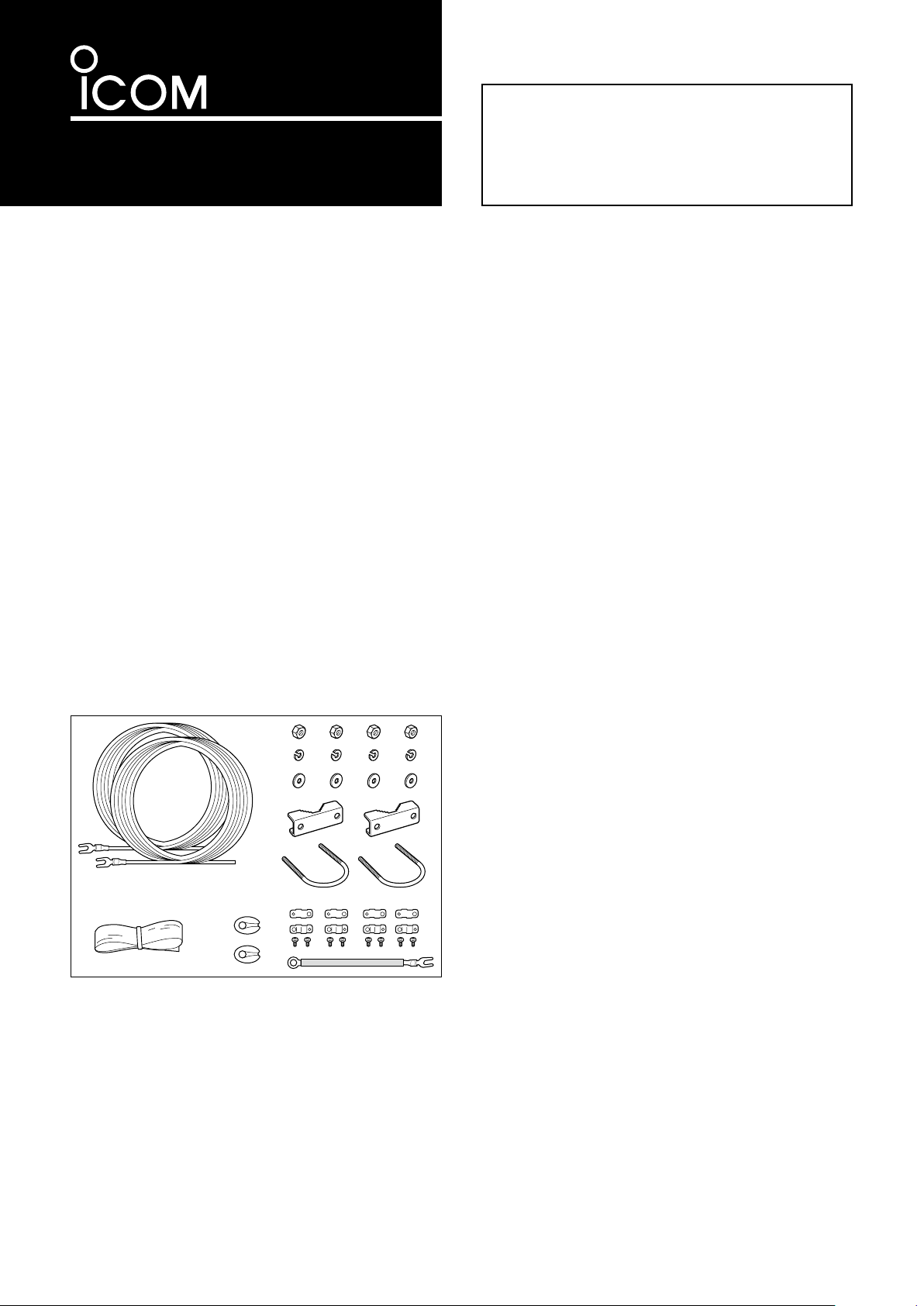
■ Supplied accessories
q Antenna wires MN-100 8 m ���������2
MN-100L 15 m ��������
w Nuts ����������������������4
e Spring washers �����������������4
r Flat washers ������������������4
t Mast mounting brackets �������������2
y U bolts ���������������������2
u Rubber vulcanizing tape �������������1
i Insulators MN-100 ������������2
MN-100L ������������
o Wire clamps MN-100 ��������� 4 sets
MN-100L ���������
!0 Grounding wire �����������������1
2 sets
■ Specifications
MN-100 : For dipole or whip antenna
MN-100L : For whip antenna only
• Max. input power : SSB 200 W pep
CW 100 W
• Frequency range : 1.5 MHz to 30 MHz
-
• Input impedance : 50
• Insertion loss : Approx. 6 dB
• VSWR : Less than 2.0 with supplied antenna
• Operating temp. : –30˚C to +80˚C; –22˚F to +176˚F
• Dimensions :
1
1
Projections not included
180(W)
Projections included
MN-100 310(W)
MN-100L 245(W)
• Weight (approx.) : MN-100 1.27 kg; 2 lb 13 oz
Ω unbalanced
wires
×65(H)×55(D) mm
; 73⁄32(W)×29⁄16(H)×25⁄32(D) in
×100(H)×58(D) mm
; 127⁄32(W)×315⁄16(H)×29⁄32(D) in
×100(H)×58(D) mm
; 921⁄32(W)×315⁄16(H)×29⁄32(D) in
MN-100L 1.23 kg; 2 lb 11 oz
■ Connector assembly
Icom, Icom Inc. and the Icom logo are registered trademarks of Icom
Incorporated (Japan) in the United States, the United Kingdom, Germany, France, Spain, Russia and/or other countries.
instructions
q PL-259 connector is not supplied with the MN-100/L, so
please prepare suitable connector for the coaxial cable
you desired to use.
w Cut end of the cable evenly. Remove vinyl jacket 29 mm
(11⁄8˝). Please do not nick the braid.
e Bare 15 mm (5⁄8˝) of the center conductor without nicking
the conductor. Trim braided shield 14 mm (
Slide the coupling ring on the cable.
r Screw the plug assembly on the cable. Solder plug as-
sembly to the braid through solder hies. Solder the conductor to the contact sleeve. Screw the coupling ring on
the assembly.
t Attach it to the connector of the MN-100/L, and cover the
connector with the supplied rubber vulcanizing tape.
9
⁄16˝) and tin it.
Page 2
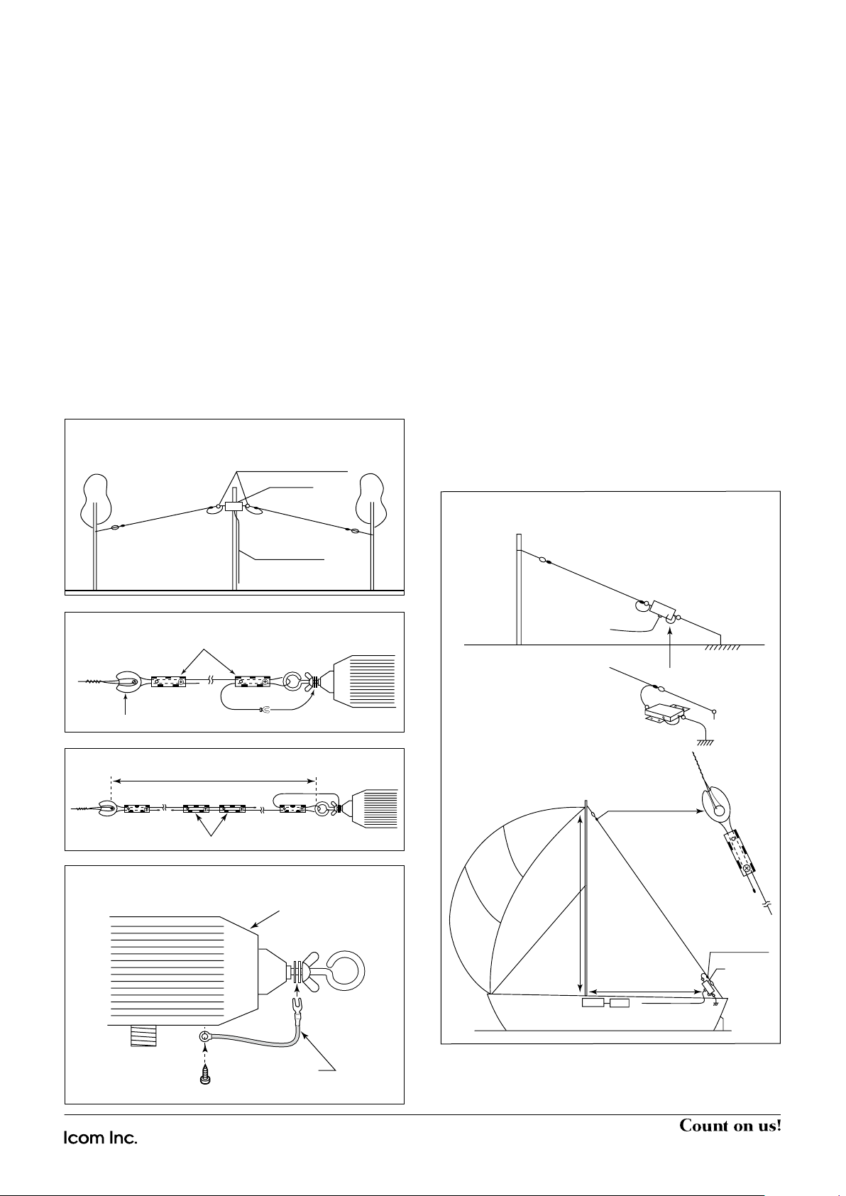
■ Installation
Coaxial cable
Wire clamp
Whip antenna
installed on a
yacht.
Ground
MN-100
or
MN-100L
MN-100
or
MN-100L
• Whip antenna
• Antenna wire joining
Wire clamp
Total length
• Grounding
wire
attaching
Grounding side
indication label
Grounding
wire
Screw to
the body
• Antenna wire installation
Wire clamp
Insulator
Antenna wire terminal
• Dipole antenna
MN-100
Coaxial cable
D Dipole antenna installation
(only MN-100 can be used)
q First, decide the place where you attempt to put the an-
tenna.
w Attach the antenna wires supplied to the terminals on the
both side of MN-100 as shown in the figure.
e If the antenna wires are too long for the place, cut the
antenna wires to desired length. At this time, each wire
should be the same length.
r Attach coaxial cable to the connector of MN-100 with a
PL-259 connector. Refer to the connector assembly instructions on the front page.
t Attach the MN-100 onto the antenna mast with the sup-
plied mounting hardware. The mounting hardware is adjusted for 25 mm to 63 mm (1˝ to 2
If your antenna mast differs from this size, please make a
mounting attachment suitable for it.
y Stretch the antenna wires to both side so that the wires
are in line, and hold each end to a mast or other suitable
construction with a wire or rope.
1
⁄2˝) tubing.
D Whip antenna installation
(both MN-100 and MN-100L can be used)
When the MN-100 is used:
q Connect the right side antenna wire terminal to the body
with the supplied grounding wire.
Then join two supplied antenna wires, and connect one
end to the left side antenna wire terminal as shown in the
figure.
When the MN-100L is used:
q Connect one end of the supplied antenna wire to the an-
tenna wire terminal.
w Attach the MN-100/L to a balustrade of the deck or other
suitable portion of the yacht or boat, where is an adequate
ground connection, with the supplied mounting hardware.
If the attached portion is not grounded or on wooden or fiberglass boat, use a copper ground plate as the ground
portion of the keel and connect between the ground terminal and there with another wire.
e Attach the other end of the antenna wire to the mast or
other suitable portion as high as possible so that the antenna wire is stretched in line.
r If the antenna wire is too long, cut the wire so that the an-
tenna wire is a stretch line when installed.
1-1-32 Kamiminami, Hirano-ku, Osaka 547-0003, Japan
A-0624D-1EX-q Printed in Japan
© 2008 Icom Inc.
 Loading...