

Page 1

INSTRUCTION MANUAL
iPCR2500
COMMUNICATIONS RECEIVER
iPCR1500
Page 2
i
FOREWORD
Thank you for purchasing this Icom radio. The IC-PCR1500/
PCR2500
COMMUNICATIONS RECEIVERS
is designed and built
with Icom’s state of the art technology and craftsmanship. With
proper care, this product should provide you with years of trouble-free operation.
DD
FEATURES
[COMMON]
❍ Wide frequency coverage with all mode
receive
❍ Real-time bandscope function
❍ IF shift function
❍
ANF and NR functions are available
(Only when the DSP unit is installed.)
[For IC-PCR2500 only]
❍ Dualwatch operation/Diversity operation
❍ DV and P25, Digital modes are available
(Only when the specific digital unit is installed.)
IMPORTANT
READ ALL INSTRUCTIONS carefully and completely
before using the receiver.
SAVE THIS INSTRUCTION MANUAL— This in-
struction manual contains important operating instructions for
the IC-PCR1500/PCR2500.
EXPLICIT DEFINITIONS
MOUSE PROPERTY SETTING
Depending on the ‘Mouse Property’ setting in the control
panel, main and sub mouse button functions are swapped.
In this instruction manual, the operation is described with
the default setting.
Icom, Icom Inc. and the logo are registered trademarks of Icom Incorporated (Japan) in the United States, the United Kingdom, Germany, France,
Spain, Russia and/or other countries.
WORD DEFINITION
R WARNING!
CAUTION
NOTE
Personal injury, fire hazard or electric shock
may occur.
Equipment damage may occur.
Recommended for optimum use. No risk of
personal injury, fire or electric shock.
Page 3

ii
SYSTEM REQUIREMENTS
PC
• Microsoft
®
Windows®XP/2000/Me/98SE installed
• USB 2.0 or 1.1
• Intel Pentium
®
III 450 MHz or faster (Pentium®4 recom-
mended)
• At least 128 MB of memory or higher (256 MB or more recommended)
• At least 50 MB or higher hard disk space
• At least 1024 × 768 pixel resolution, high color display
• CD-ROM or DVD drive is required for software installation.
• Mouse or other compatible pointing device is required.
• USB audio dropouts or gaps may occur, because of a
lack of PC power.
• Additional hard disk space is required for;
- Recording sound (at high quality): max 300 MB (approx.)
- Storing scope data
Frequency mode : max 5 MB (approx.)
Time mode : max 1.5 MB (approx.)
- Memory channel data : max 500 kB (approx.)
SUPPLIED ACCESSORIES
q Antenna …………………………………………………… 1
w AC adapter* ……………………………………………… 1
e USB cable ………………………………………………… 1
r CD ………………………………………………………… 1
t Foot pad sheet……………………………………………… 1
y Cable hanger ……………………………………………… 1
*Not supplied with some versions.
y
tre
qw
Microsoft, Windows and Windows Media are registered trademarks of Microsoft
Corporation in the U.S.Aand other countries. Screen shots produced with permission from Microsoft Corporation.
Pentium is a registered trademark of Intel Corporation.
All other products or brands are registered trademarks or trademarks of their
respective holders.
Page 4

iii
PRECAUTIONS
RWARNING! NEVER connect the OPC-254L to an
AC outlet. This may pose a fire hazard or result in an electric
shock.
NEVER expose the receiver to rain, snow or any liquids.
The receiver may be damaged.
NEVERoperate or touch the receiver with wet hands. This
may result in an electric shock or damage the receiver.
AVOID using or placing the receiver in direct sunlight or in
areas with temperatures below 0°C (+32°F) or above +60°C
(+140°F).
AVOID the use of chemical agents such as benzine or al-
cohol when cleaning, as they can damage the receiver’s surfaces.
DO NOT use the supplied CD for any other devices.
The CD is for the IC-PCR1500/R1500, IC-PCR2500/R2500
only.
DO NOT turn the Main unit power OFF or disconnect the
USB cable between the Main unit and PC while IC-PCR1500
or IC-PCR2500 control software is running. This may result
in the computer hang up.
DO NOTstart vehicle engine while the IC-PCR1500 or IC-
PCR2500 control software is running when optional CP-12L is
connected to a cigarette lighter socket. This may result in the
computer hang up.
DO NOT leave the Main unit for long time with power
switch ON condition, because approx. 55 mA current is still
drained. This cause vehicle’s battery will become exhausted.
For DC power operation
(while connecting an OPC-254L or CP-12L)
NEVER connect the receiver to a power source of more
than 13.9 V DC. This will damage the receiver.
NEVER connect the receiver to a power source using re-
verse polarity. This will damage the receiver.
NEVER cut the DC power cable between the DC plug and
fuse holder. If an incorrect connection is made after cutting,
the receiver may be damaged.
If a connection cable is disconnected or has a loose connection during operation, an error may occur. Connect the connectors correctly, and
DO NOT touch the connectors
during operation.
Page 5

ABOUTAPCO PROJECT 25
iv
For the operation of PC and peripheral devices, follow the instructions provided in the manuals which come with the PC
and peripheral devices.
This device may cause signal interference when used in a domestic setting. When interference occurs, move this unit as
far as possible away from the affected device.
All copyrights associated with this manual and all intellectual
property rights associated with the hardware and software of
the IC-PCR1500/PCR2500 are held by Icom Inc.
Unauthorized reproduction or transmission of this manual, or
any part hereof, is prohibited.
The content of this manual, the hardware and software associated with the IC-PCR1500/PCR2500, and the appearance
of the IC-PCR1500/PCR2500 are all subject to change without notice.
For U.S.A. only
CAUTION: Changes or modifications to this device, not ex-
pressly approved by Icom Inc., could void your authority to
operate this device under FCC regulations.
This device made under license under one or more of the following US patents: #4,590,473, #4,636,791, #5,148,482,
#5,185,796, #5,271,017, #5,377,229.
The IMBE™ voice coding Technology embodied in this product is protected by intellectual property rights including patent
rights, copyrights and trade secrets of Digital Voice Systems,
Inc. This voice coding Technology is licensed solely for use
within this Communications Equipment. The user of this Technology is explicitly prohibited from attempting to decompile, reverse engineer, or disassemble the Object Code, or in any
other way convert the Object Code into a human-readable
form. U.S. Pat. Nos. #5,870,405, #5,826,222, #5,754,974,
#5,701,390, #5,715,365, #5,649,050, #5,630,01 1, #5,581,656,
#5,517,511, #5,491,772, #5,247,579, #5,226,084, #5,195,166.
P25 digital mode is available when optional UT-122
DIGITAL
UNIT
is installed to IC-PCR2500 or IC-R2500.
Page 6

v
TABLE OF CONTENTS
FOREWORD …………………………………………… i
IMPORTANT …………………………………………… i
EXPLICIT DEFINITIONS ……………………………… i
MOUSE PROPERTY SETTING ……………………… i
SYSTEM REQUIREMENTS ………………………… ii
SUPPLIED ACCESSORIES ………………………… ii
PRECAUTIONS ……………………………………… iii
ABOUTAPCO PROJECT 25 ……………………… iv
TABLE OF CONTENTS ……………………………… v
1 INSTALLATION ………………………………… 1–3
■ Hardware installation …………………………… 1
■ TNC connection ………………………………… 2
■ DC power supply connection …………………… 2
■ Accessory attachments ………………………… 3
2 DRIVER INSTALLATION …………………… 4–24
■ Microsoft
®
Windows®XP ……………………… 4
■ Microsoft®Windows®2000 …………………… 10
■ Microsoft®Windows®98SE …………………… 16
■ Microsoft®Windows®Me ……………………… 20
3 APPLICATION INSTALLATION …………… 25–29
■ Installation ……………………………………… 25
■ Launching the IC-PCR1500_2500 …………… 27
■ Uninstall ………………………………………… 28
4PANEL DESCRIPTION ……………………… 30–43
■ Application screens
(on PC screen) …………… 30
■ Main unit ………………………………………… 42
5 BASIC RECEIVE FUNCTIONS …………… 44–67
■ Starting the control software ………………… 44
■ Changing the control screen ………………… 44
■ Closing the control screen …………………… 46
■ Quitting the control software ………………… 46
■ Receiving ……………………………………… 47
■ Setting a frequency …………………………… 48
■ Setting a tuning step …………………………… 50
■ Audio level setting ……………………………… 52
■ Squelch level setting …………………………… 53
■ Receive mode selection ……………………… 54
■ Automatic mode selection …………………… 55
■ Monitor function ………………………………… 56
■ Mute function …………………………………… 56
■ Duplex operation ……………………………… 57
■ IF filter selection ……………………………… 58
■ AFC function …………………………………… 59
■ Attenuator function……………………………… 59
■ NB function ……………………………………… 60
■ AGC function …………………………………… 60
■ VSC function …………………………………… 61
Page 7

■ IF shift function ………………………………… 61
■ Weather channel operation
(USA and CANADA versions only) ……………… 62
■ Squelch delay setting ………………………… 63
■ Single band/Dualwatch operation
(IC-PCR2500 only) ……………………………… 64
■ Diversity operation (IC-PCR2500 only) ………… 66
■ Main/Sub band selection (IC-PCR2500 only) …67
6 MEMORY CHANNELS ……………………… 68–79
■ General ………………………………………… 68
■ Memory channel selection …………………… 68
■ Memory channel programming ……………… 70
■ Editing the memory list ………………………… 72
■ Memory channel clearing ……………………… 76
■ Saving memory channel data ………………… 78
■ Opening memory channel data ……………… 78
■ Creating new memory channel data file …… 78
■ Printing a memory channel …………………… 78
■ Importing a CSV file …………………………… 79
■ Exporting a CSV file …………………………… 79
7 SCAN OPERATION
(Multi function receiver/Component screens only) 80–91
■ Scan types ……………………………………… 80
■ Programmed scan ……………………………… 81
■ Auto memory write scan ………………………84
■ Memory/bank scan …………………………… 86
■ Versatile memory scan ………………………… 88
■ Scan resume condition ………………………… 90
■ Scan speed setting …………………………… 91
8 PRIORITY SCAN
(Multi function receiver/Component screens only) 92–80
■ Priority scan type ……………………………… 92
■ Priority scan operation ………………………… 92
9TONE SQUELCH OPERATION
(Multi function receiver/Component screens only) … 94–97
■ Tone/DTCS operation ………………………… 94
■ DTCS polarity setting ………………………… 96
■ Pocket beep operation ………………………… 96
■ Tone scan operation …………………………… 97
10BAND SCOPE
(Multi function receiver/Component screens only) … 98–89
■ Operation ……………………………………… 98
■ Pick up signal function ……………………… 100
■ Saving the sweep data ……………………… 100
■ Changing the automatic sweep step limit … 102
■ Wide band scope function …………………… 103
■ Band scope options ………………………… 103
11OTHER FUNCTION ……………………… 104–116
■ DTMF Operation ……………………………… 104
vi
1
2
3
4
5
6
7
8
9
10
11
12
13
14
15
16
17
18
19
20
21
22
23
TABLE OF CONTENTS (Continued)
Page 8

vii
■ Audio setting screen ………………………… 106
■ Multi channel monitor ………………………… 110
■ Recording operation ………………………… 112
■ Sampling Rate setting ……………………… 114
■ Remote recording function ………………… 115
■ Short cut key operation ……………………… 116
12DSP OPERATION
(Available only when the UT-106 is installed) ………… 117
■ ANF function ………………………………… 117
■ NR function …………………………………… 117
13DIGITAL MODE OPERATION
(IC-PCR2500 Main band only) ………………… 118–123
■ Digital mode operation ……………………… 118
■ DV mode setting ……………………………… 117
■ DV digital squelch function ………………… 120
■ P25 mode setting …………………………… 121
■ P25 digital squelch function …………………122
■ Digital menu indication ……………………… 123
■ DV Digital menu ……………………………… 124
■ P25 Digital menu ……………………………… 125
14OPTIONAL UNIT INSTALLATION ……… 126–128
■ Opening the top cover ……………………… 126
■ UT-106 installation …………………………… 126
■ UT-108/UT-118 installation
(IC-PCR2500/R2500 only) ………………………128
■ UT-122 installation
(IC-PCR2500/R2500 only) ………………………128
15INTERNAL AUDIO SWITCH ………………… 129
16USB PORT SETTING ………………………… 130
■ USB port setting ……………………………… 130
■ USB audio setting …………………………… 131
17CLONING OPERATION
(Available only when the IC-R1500 or IC-R2500 is connected)
…………………………………………………… 132
18TROUBLESHOOTING ………………………… 133
19SPECIFICATIONS AND OPTIONS …… 134–136
■ Specifications …………………………………134
■ Options ………………………………………… 136
20DOC ………………………………………… 137–138
In this instruction manual, the screen shot contents may
be different from the actual one.
TABLE OF CONTENTS (Continued)
Page 9

1
1
INSTALLATION
1
■ Hardware installation
Refer to the diagram below for connections.
CAUTION: Icom Inc. assumes no responsibility for the receiver’s operation resulting from the use of any other USB
cable other than the one supplied by Icom in the original
IC-PCR1500 or IC-PCR2500 package.
NOTE: The antenna’s double sided tape may not adhere
to all items. Additionally, the tape is not intended for multiple uses. Lastly, some items may be damaged by trying to
remove the antenna holder once it has been taped into
place. Icom Inc cannot accept any responsibility for any
damage to any item caused by the supplied tape.
The antenna holder comes with
double sided tape attached to it.
Remove the protective paper
and adhere the antenna to the
location you desire.
R WARNING!: NEVER use
a gas pipe or electrical conduit pipe for grounding.
Or
Fuse (4 A)
Supplied antenna
To ground
To AC adapter
The dualwatch operation or diversity operation
for IC-PCR2500 or IC-R2500 requires both
antenna connections to [ANT1] and [ANT2].
IC-PCR2500
PC
to USB port
CP-12L
(optional)
USB cable
To a cigarette lighter socket
Page 10

2
1
INSTALLATION
■ TNC connection
The IC-PCR1500/PCR2500 can receive 9600 bps packet
communication (AFSK) with the use of a TNC (not supplied).
Connect the TNC (Terminal Node Controller) as illustrated
below. (Other connections are same as page 1.)
■ DC power supply connection
Use a 12 V DC power supply with at least 1.2 Acapacity.
Make sure the ground terminal of the DC power supply is
grounded.
OPC-254L
(optional)
black
white
R CAUTION! NEVER remove the
fuse-holders from the DC power cable.
Connects to a 12 V DC
battery. Pay attention
to polarities. NEVER
connect to a 24 V battery. This could damage the receiver.
Solder
Crimp
NOTE: Use the terminals as shown
below for the cable connections.
D Fuse replacement
IC-PCR2500
Fuses (4 A)
DC power
supply 12 V
to an
AC outlet
−⊕
PACKET
GND
2-conductor 3.5 (d) mm
(1⁄8˝)/100 kΩ
D PACKET jack connection
TNC
IC-PCR2500
PC
Page 11

3
1
INSTALLATION
1
■ Accessory attachments
D Foot pad
Attach 4 foot pads to the bottom of the IC-PCR1500/
PCR2500 as below.
D Cable hanger
The cable hanger is convenient for fixing a cable to the wall,
etc.
Cable
Clinch the hook.
Remove the protective paper.
Foot pad sheet
(supplied)
IC-PCR2500
Foot pad
Detach 4 foot pads
from the foot pad
sheet.
Page 12

4
DRIVER INSTALLATION
2
The displayed dialog boxes or indications may differ
slightly from the following instructions according to your
system conditions, or environment.
■ Microsoft®Windows®XP
NOTE: Driver installation with CD is required when an ad-
ditional Main unit is connected to the PC (i.e. 2 or more ICPCR1500 or IC-PCR2500s (same model only) are
connected to the PC). In such a case, install the driver as
shown below.
qQuit all applications when Windows is running.
wConnect the Main unit to the desired PC’s USB port with
the supplied USB cable.
CAUTION: Icom Inc. assumes no responsibility for the
receiver’s operation resulting from the use of any other
USB cable other than the one supplied by Icom in the
original IC-PCR1500 or IC-PCR2500 package.
eInsert the CD into the appropriate CD drive.
rTurn the Main unit power ON.
• The power indicator lights.
• “Found New Hardware” appears as below.
tThe CP2101 USB device is detected automatically, and the
“Found New Hardware Wizard” will come up as below.
Select “Install from a list or specific location (Advanced),”
then click [Next>].
Click
Select
Page 13

5
2
DRIVER INSTALLATION
2
ySelect “Search for the best driver in these locations.” then
select “Include this location in the search,” click [Browse].
uClick “ ” of the CD drive folder in “My Computer.”
• The CD drive folder name (e.g. “D”) is depending on a PC.
iClick “ ” of the “Driver” folder in the CD drive folder, then
select “Win” folder.
Click [OK].
Click
Select
Click
Click
Select
Select
Page 14
6
2
DRIVER INSTALLATION
oClick [Next>].
!0The Wizard starts searching for the driver and shows the
dialog below during search.
!1After the driver is found, the “Hardware Installation” dialog
box appears as below.
Click [Continue Anyway] to start the installation.
!2Windows starts installing the USB driver.
Click
Click
Page 15
7
2
DRIVER INSTALLATION
2
!3After the installation is completed, click [Finish].
!4The “Found New Hardware Wizard” will come up again to
install the USB serial port driver.
Select “Install from a list or specific location (Advanced),”
then click [Next>].
!5Select “Search for the best driver in these locations.” then
select “Include this location in the search:”, click [Browse].
!6Click “ ” of the CD drive folder in “My Computer.”
• The CD drive folder name (e.g. “D”) is depending on a PC.
Click
Click
Select
Select
Click
Select
Click
Page 16
8
2
DRIVER INSTALLATION
!7Click “ ” of the “Driver” folder in the CD drive folder, then
select “Win” folder.
Click [OK].
!8Click [Next>].
!9The Wizard starts searching for the driver and shows the
dialog below during search.
@0After the driver is found, the “Hardware Installation” dialog
box appears as below.
Click [Continue Anyway] to start the installation.
Click
Click
Click
Select
Page 17

9
2
DRIVER INSTALLATION
2
@1Windows starts installing the USB driver.
@2After the installation is completed, click [Finish].
@3After clicking [Finish], the dialog appears as below.
@4Eject the CD.
• Restarting the PC is recommended.
Click
Page 18

10
2
DRIVER INSTALLATION
■ Microsoft®Windows®2000
NOTE: Driver installation with CD is required when an ad-
ditional Main unit is connected to the PC (i.e. 2 or more ICPCR1500 or IC-PCR2500s (same model) are connected
to the PC). In such a case, install the driver as shown
below.
qQuit all applications when Windows is running.
wConnect the Main unit to the desired PC’s USB port with
the supplied USB cable.
CAUTION: Icom Inc. assumes no responsibility for the
receiver’s operation resulting from the use of any other
USB cable other than the one supplied by Icom in the
original IC-PCR1500 or IC-PCR2500 package.
eInsert the CD into the appropriate CD drive.
rTurn the Main unit power ON.
• The power indicator lights.
• “Found New Hardware” appears as below.
tThe CP2101 USB device is detected automatically, and the
“Found New Hardware Wizard” will come up as below.
Click [Next>].
ySelect “Search for a suitable driver for my device (recom-
mended),” then click [Next>].
Click
Select
Click
Page 19

11
2
DRIVER INSTALLATION
2
uSelect “Specify a location,” then click [Next>].
iClick [Browse...].
oSelect the CD drive in “My Computer,” then click [Open].
• The CD drive folder name (e.g. “D”) is depending on a PC.
!0Select the “Driver” folder in the CD drive, then click [Open].
Click
Click
Click
Click
Click
Click
No check
marks ✔
Select
Page 20

12
2
DRIVER INSTALLATION
!1Select “Win” in the “Driver” folder, then click [Open].
!2Select “Slabbus” in the “Win” folder, then click [Open].
!3Click [OK].
!4When the driver is found, the following dialog is displayed.
Click [Next>] to start the installation.
Click
Click
Click
Click
Click
Click
Page 21

13
2
DRIVER INSTALLATION
2
!5After the installation is completed, click [Finish].
!6The “Found New Hardware Wizard” appears again.
Click [Next>].
!7Select “Search for a suitable driver for my device (recom-
mended),” then click [Next>].
!8Select “Specify a location,” then click [Next>].
Click
No check
marks ✔
Select
Click
Select
Click
Click
Page 22

14
2
DRIVER INSTALLATION
!9Click [Browse...].
@0Select the CD drive in “My Computer,” then click [Open].
• The CD drive folder name (e.g. “D”) is depending on a PC.
@1Select the “Driver” folder in the CD drive, then click [Open].
@2Select “Win” in the “Driver” folder, then click [Open].
Click
Click
Click
Click
Click
Click
Click
Page 23

15
2
DRIVER INSTALLATION
2
@3Select “Slabw2k” in the “Win” folder, then click [Open].
@4Click [OK].
@5When the driver is found, the following dialog is displayed.
Click [Next>] to start the installation.
@6After the installation is completed, click [Finish].
@7Eject the CD.
• Restarting the PC is recommended.
Click
Click
Click
Click
Click
Page 24

16
2
DRIVER INSTALLATION
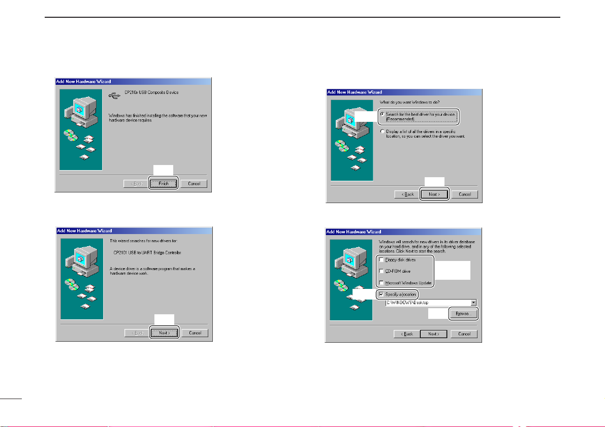
■ Microsoft®Windows®98SE
qQuit all applications when Windows is running.
wConnect the Main unit to the desired PC’s USB port with
the supplied USB cable.
CAUTION: Icom Inc. assumes no responsibility for the
receiver’s operation resulting from the use of any other
USB cable other than the one supplied by Icom in the
original IC-PCR1500 or IC-PCR2500 package.
eInsert the CD into the appropriate CD drive.
rTurn the Main unit power ON.
• The power indicator lights.
tThe CP2101 USB device is detected automatically, and the
“Add New Hardware Wizard” will come up as below. Click
[Next>].
ySelect “Search for the best driver for your device. (Recom-
mended),” then click [Next>].
uSelect “Specify a location:”, click [Browse...].
Click
Select
No check
marks ✔
Click
Select
Click
Page 25

17
2
DRIVER INSTALLATION
2
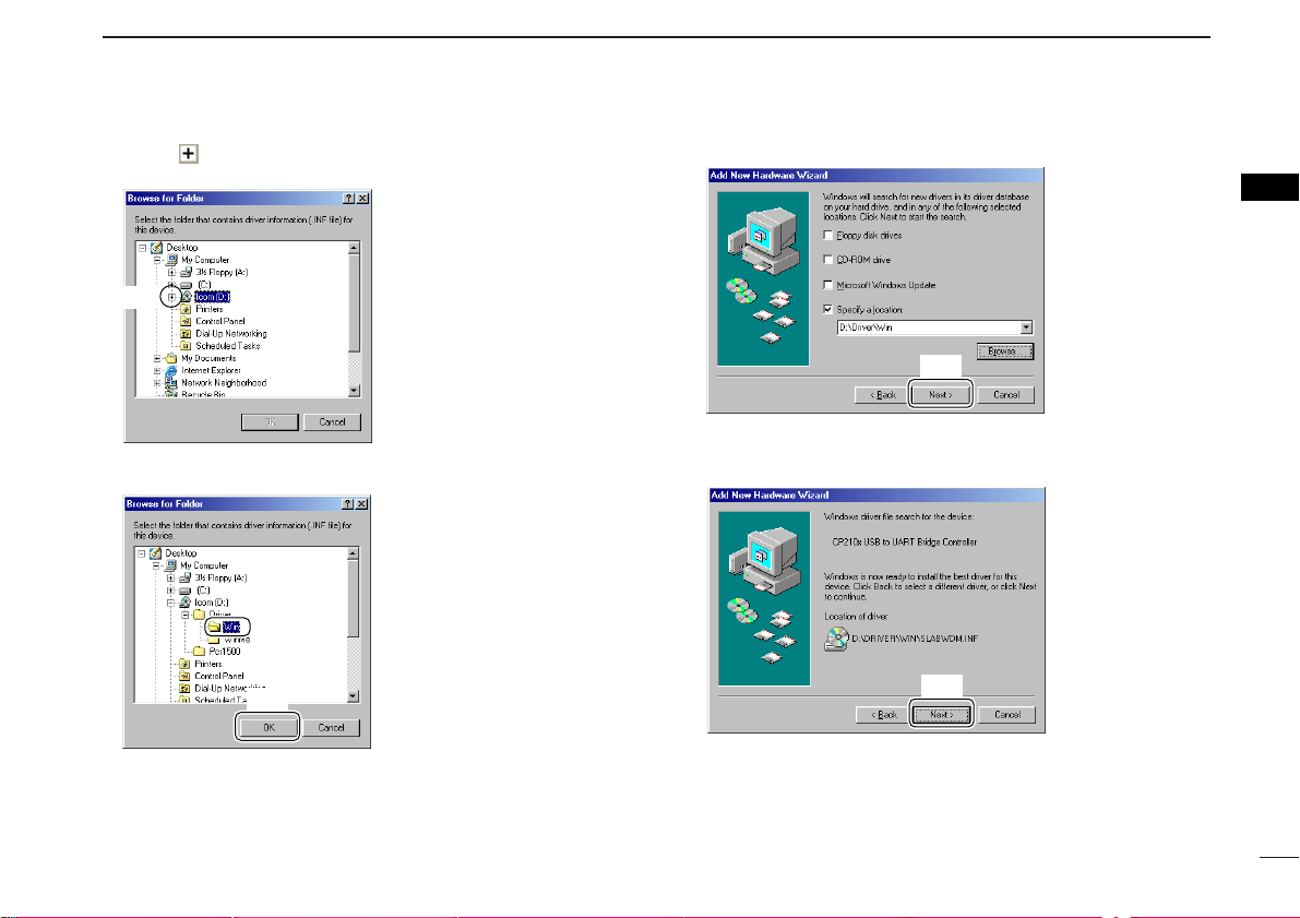
iClick “ ” of the CD drive folder in “My Computer”.
• The CD drive folder name (e.g. “D”) is depending on a PC.
oSelect “Win” in the “Driver” folder, click [OK.]
!0Click [Next>].
!1When the driver is found, the following dialog is displayed.
Click [Next>] to start the installation.
Click
Click
Click
Select
Click
Page 26
18
2
DRIVER INSTALLATION
!2After the installation is completed, click [Finish].
!3The “Add New Hardware Wizard” appears again.
Click [Next>].
!4Select “Search for the best driver for your device. (Recom-
mended),” then click [Next>].
!5Select “Specify a location:”, click [Browse...].
Click
Select
No check
marks ✔
Click
Select
Click
Click
Page 27
19
2
DRIVER INSTALLATION
2
!6Click “ ” of the CD drive folder in “My Computer.”
• The CD drive folder name (e.g. “D”) is depending on a PC.
!7Select “Win” in the “Driver” folder, click [OK].
!8Click [Next>].
!9When the driver is found, the following dialog is displayed.
Click [Next>] to start the installation.
Click
Click
Click
Select
Click
Page 28
20
2
DRIVER INSTALLATION
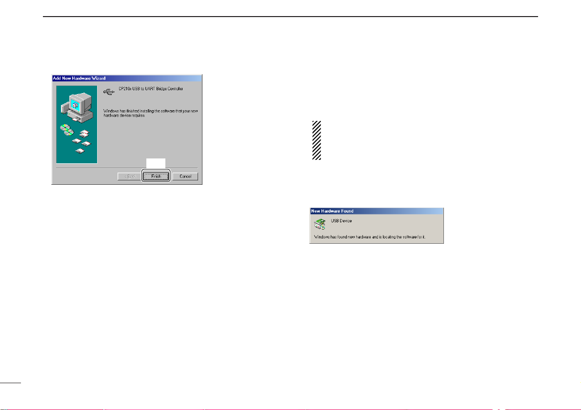
@0After the installation is completed, click [Finish].
@1Eject the CD.
• Restarting the PC is recommended.
■ Microsoft®Windows®Me
qQuit all applications when Windows is running.
wConnect the Main unit to the desired PC’s USB port with
the supplied USB cable.
CAUTION: Icom Inc. assumes no responsibility for the
receiver’s operation resulting from the use of any other
USB cable other than the one supplied by Icom in the
original IC-PCR1500 or IC-PCR2500 package.
eInsert the CD into the appropriate CD drive.
rTurn the Main unit power ON.
• The power indicator lights.
• “New Hardware Found” appears as below.
Click
Page 29
21
2
DRIVER INSTALLATION
2
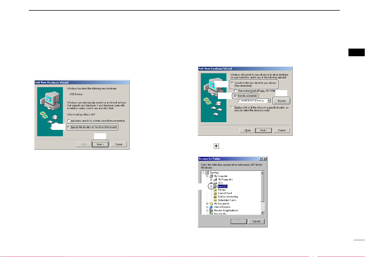
tThe CP2101 USB device is detected automatically, and the
“Add New Hardware Wizard” will come up as below.
Select “Specify the location of the driver (Advanced),” then
click [Next>].
ySelect “Search for the best driver for your device. (Recom-
mended),” then select “Specify a location:”, click [Browse].
uClick “ ” of the CD drive folder in “My Computer.”
• The CD drive folder name (e.g. “D”) is depending on a PC.
Click
Click
Select
Select
Click
Select
Page 30
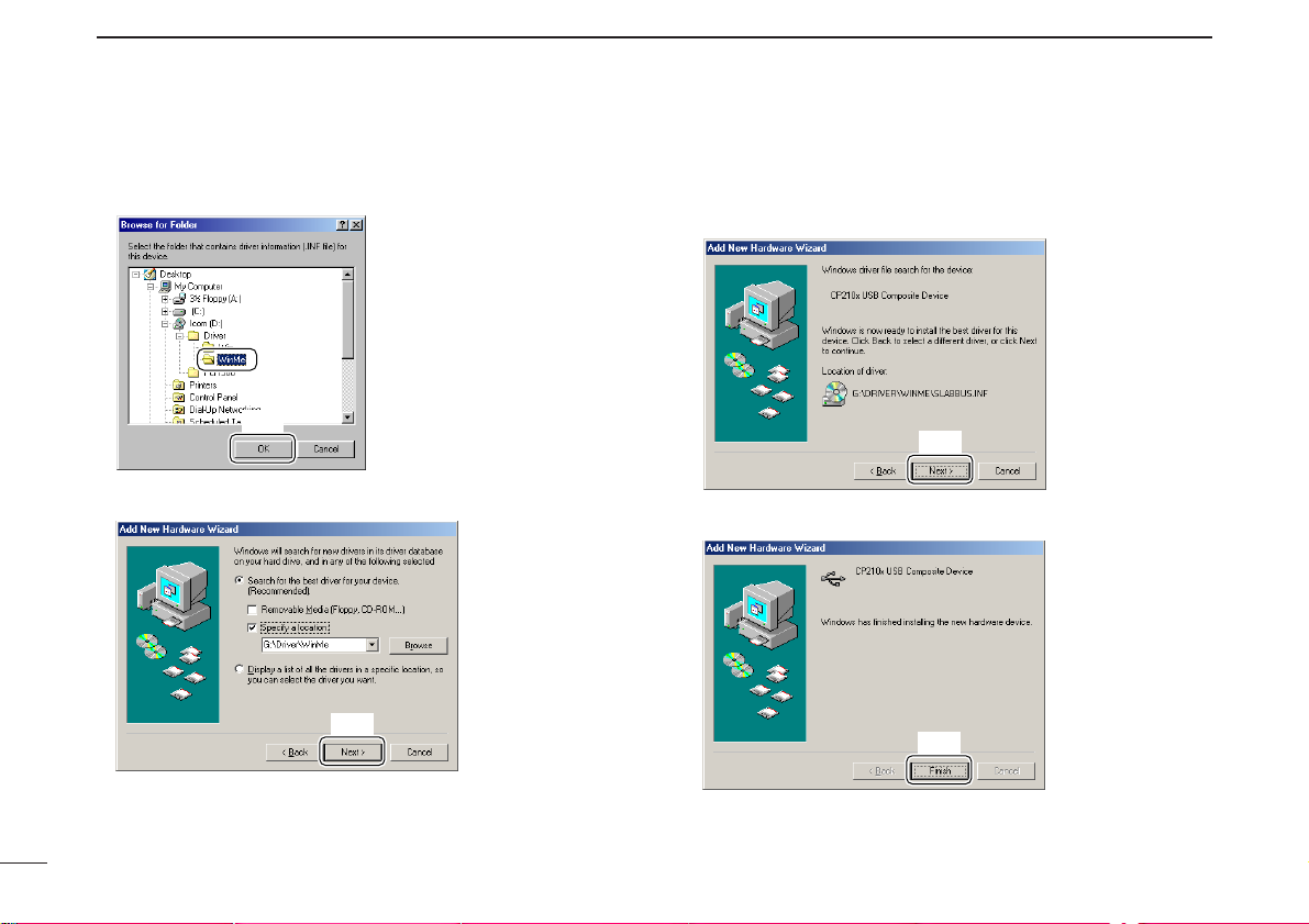
22
2
DRIVER INSTALLATION
iSelect “WinMe” in the “Driver” folder, click [OK].
oClick [Next>].
!0When the driver is found, the following dialog is displayed.
Click [Next>] to start the installation.
!1After the installation is completed, click [Finish].
Click
Click
Click
Click
Select
Page 31

23
2
DRIVER INSTALLATION
2
!2The “Add New Hardware Wizard” appears again. Select
“Specify the location of the driver (Advanced),” then click
[Next>].
!3Select “Search for the best driver for your device. (Recom-
mended),” then select “Specify a location:”, click [Browse].
!4Click “ ” of the CD drive folder in “My Computer.”
• The CD drive folder name (e.g. “D”) is depending on a PC.
!5Select “WinMe” in the “Driver” folder, click [OK].
Click
Select
Click
Click
Select
Select
Click
Page 32

24
2
DRIVER INSTALLATION
!6Click [Next>].
!7When the driver is found, the following dialog is displayed.
Click [Next>] to start the installation.
!8After the installation is completed, click [Finish].
!9Eject the CD.
• Restarting the PC is recommended.
Click
Click
Click
Page 33

25
3
APPLICATION INSTALLATION
2
3
■ Installation
qQuit all applications when Windows is running.
wInsert the CD into the CD drive.
eOpen the CD drive contents via “My computer” or “Win-
dows Explorer.”
• “Driver” and “pcr1500_2500” folders are included.
rDouble click “Setup.exe” file in “Pcr1500_2500” folder.
• The “InstallShield®Wizard” starts preparing the installation.
tSelect the display language type from “English” or “Japan-
ese.” Click [OK].
yAfter the preparation, the following dialog is displayed.
Click [Next>].
Click
Click
Double click
_2500
Page 34

26
3
APPLICATION INSTALLATION
uConfirm the location, then click [Next>] to start the installation.
• Click [Browse...] then type the desired location if you specifying
the installation location.
• The installation starts.
iAfter the installation is completed, click [Finish].
oEject the CD.
• The IC-PCR1500 2500 shortcut icon is created on the desktop.
• Restarting the PC is recommended.
Click
Click
Page 35

27
3
APPLICATION INSTALLATION
3
D Microsoft
®
Windows®XP
qBefore launching the program, please be sure the Main
unit is turned ON.
• The power indicator lights green.
wClick the [Start] button and point to [All Programs].
ePoint to the “IC-PCR1500_2500” folder.
rClick the “IC-PCR1500_2500” program.
(or simply double click the desktop short cut icon as below, which
was automatically created during application installation.)
D Microsoft®Windows®98SE/Me/2000
qBefore launching the program, please be sure the Main
unit is turned ON.
• The power indicator lights green.
wClick the [Start] button and point to [Programs].
ePoint to the “IC-PCR1500_2500” folder.
rClick the “IC-PCR1500_2500” program.
(or simply double click the desktop short cut icon as below, which
was automatically created during application installation.)
q
w
e
r
Short cut icon
q
w
e
r
Short cut icon
NOTE: Launch the program after
approx. 20 sec. has passed when
the “Communication error” occurs.
NOTE: Launch the program after
approx. 20 sec. has passed when
the “Communication error” occurs.
■ Launching the IC-PCR1500_2500
Page 36

28
3
APPLICATION INSTALLATION
In this section, screen shots of Windows XP are used for the
instruction example. However, the instructions are similar to
the other operating systems, Windows 98SE, Me and 2000.
qStart up Windows.
wSelect the “Control Panel” in the Start menu.
• The control panel appears as shown in the next step below.
eClick the “Add or Remove Programs.”
• The “Add or Remove Programs” menu appears.
rClick the “Icom IC-PCR1500/2500,” then click [Change/Re-
move].
• The “InstallShield®Wizard” starts preparing the installation.
tSelect the display language type from “English” or “Japan-
ese,” click [OK].
Click
Click
Click
■ Uninstall
Page 37

29
3
APPLICATION INSTALLATION
3
yAfter the preparation, “Confirm Uninstall” appears, click
[OK] to remove the program from the PC.
• The uninstallation starts.
uAfter the uninstall is completed, click [Finish].
Click
Click
Page 38

qCOMPONENT BUTTON (pgs. 37, 45)
Click to display the Component screen.
wSIMPLE BUTTON (pgs. 36, 46)
Click to display the Simple screen.
eMULTI CHANNELMONITOR BUTTON (p. 110)
Click to make the multi channel monitor screen appear/disappear.
rDIGITAL MODE OPERATION BUTTON (p. 118)
Click to select the DV mode items or P25 mode items.
tDIVERSITY OPERATION BUTTON (p. 66)
Click to make the diversity reception mode ON and OFF.
yAUDIO SETTING BUTTON (p. 106)
Click to make the audio setting screen appear/disappear.
uCLONE BUTTON (p. 132)
Click to make the cloning screen appear/disappear.
iEXIT BUTTON (p. 46)
Click to quit the control program.
oMAIN/SUB BUTTONS (p. 67)
Click to select the Main band/Sub band during dualwatch
operation.
!0USB PORT SETTING BUTTON (p. 130)
Click to make the USB setting screen appear.
IC-PCR2500 IC-PCR1500
!2
!4
!1
!0
!5
!6
!7
!8 q
w
e
u
y
i
!4
!3
!2
!5
!6
!7
!8 q
w
e
t
r
y
!0
!1 u
o
i
■ Application screens (on PC screen)
D Tool bar
The application screen can be seen after the application installation. See page 25 for details.
30
PANEL DESCRIPTION
4
Page 39

31
4
PANEL DESCRIPTION
4
!1SETTING BUTTON
For IC-PCR1500 (pgs. 55, 116)
Click to make the auto mode setting list, short cut key list
and etc. screen appear/disappear.
For IC-PCR2500 (pgs. 55, 116, 119, 121)
Click to make the auto mode setting list, short cut key list,
DV*
1
mode setting, P25*2mode setting and etc. screen ap-
pear/disappear.
*1: The optional UT-118 is required.
*2: The optional UT-122 is required.
Some versions are already installed UT-122, additional installation is not necessary.
!2RECORDING BUTTON (p. 112)
Click to make the recording screen appear/disappear.
!3SINGLE BAND/DUALWATCH BUTTON (p. 64)
Click to toggle the single band operation and dualwatch operation.
!4DSP DIGITAL FILTER BUTTON (pgs. 117)
Click to make the DSP digital filter screen appear/disappear.
!5DTMF REMOTE COMMANDER BUTTON (p. 104)
For IC-PCR1500
Click to make the DTMF remote commander screen appear/disappear.
For IC-PCR2500
Click to make the DTMF remote commander screen appear/disappear for main band (right button) and sub band
(left button). The DTMF remote commander screen for sub
band can not access during single band operation or diversity reception mode.
!6MEMORY CHANNEL BUTTON (pgs. 69, 112)
Click to make the memory channel screen appear/disappear.
!7MULTI-FUNCTION RECEIVER BUTTON (pgs. 32, 44)
Click to display the [Receiver] screen.
!8POWER BUTTON (p. 44)
Click to make the control program connection to Main unit
connect/disconnect.
Page 40

32
4
PANEL DESCRIPTION
D [Receiver] (Multi-function receiver) screen
!4
!5
!3
@0
@9@8@7 #1 #2
#6
#5
$4
$5
q
#4
#3
@6@5 #0
@2@1
!6
$8
e
w
$7
$6
t
y
u
i
r
o
!0
!1
!2
!7 !8 !9 @3 @4
#7
#8
#9
$0
$1
$3b
$2
$3
IC-PCR2500
single band operation
Page 41

33
4
PANEL DESCRIPTION
4
qCLOSE BUTTON (p. 46)
Click to quit and exit the application screen.
wMINIMIZE BUTTON
Click to minimize the application screen.
eRECEIVE MODE BUTTONS ([SSB], [CW], [AM], [WFM],
[FM], [DV]*
1
, [P25]*2and [AUTO-M]) (pgs. 54, 55)
Click to select a receive mode.
• When using [AUTO-M] (automatic mode), a receive mode, IF
filter passband width, tuning step, etc., are selected automatically
after inputting a frequency.
*1,*2: For IC-PCR2500 only.
*1: The optional UT-118 is required.
*2: The optional UT-122 is required.
Some versions are already installed UT-122, additional installation is not necessary.
rSCAN SPEED CONTROL [SPEED] (p. 91)
Click to set the scan speed at which channels or frequencies are searched during scan operation.
• Right-click to increase the speed level. (Scan is faster)
• Left-click to decrease the speed level. (Scan is slower)
tSCAN DELAY TIME CONTROL [DELAY]
Click to set the period in which a scan pauses after receiving a signal.
• Right-click to increase the period.
• Left-click to decrease the period.
ySET BUTTON [SET] (p. 90)
Click to show the [Scan Delay] screen.
This screen is used for the settings of the scan delay
details.
uAUDIO FREQUENCY GAIN CONTROL [AF GAIN] (p. 52)
Click to adjust the audio output level.
• Right-click to increase the audio output level.
• Left-click to decrease the audio output level.
iSQUELCH CONTROL [SQUELCH] (p. 53)
Click to adjust the squelch threshold level.
The squelch removes noise output from the speaker
(closed condition) when no signal is received.
• Right-click to close the squelch.
• Left-click to open the squelch.
oMONITOR BUTTON [MONI] (p. 56)
Click to turn the monitor function ON or OFF.
The monitor function is used to temporarily open the
squelch to listen for a weak signal.
!0MUTE BUTTON [MUTE] (p. 56)
Click to turn the mute function ON or OFF.
This function is used to temporarily mute the audio output.
!1TUNING DIAL (p. 48)
Click to set the receive frequency with the selected tuning
step.
• Right-click to increase the frequency.
• Left-click to decrease the frequency.
!2DUPLEX BUTTON [DUP] (p. 57)
➥ Right-click to display the offset frequency setting screen.
➥ Left-click to set the duplex direction from OFF (no
indication), DUP –, and DUP +.
!3TUNING STEP UP/DOWN BUTTONS [Y]/[Z] (p. 50)
➥ Right-click to display the tuning step setting screen.
➥ Left-click to select the tuning steps in order.
Page 42

34
4
PANEL DESCRIPTION
!4IF-SHIFT CONTROL (p. 61)
Click to set a signal passband position.
• Right-click to increase the signal passband position.
• Left-click to decrease the signal passband position.
!5CENTER KEY [CENTER] (p. 61)
After setting a signal passband position with clicking the IFshift control, click to return to the center position.
!6IF FILTER BUTTONS [WIDE]/[NAR] (p. 58)
Click to change the IF filter in use.
• Click [WIDE] to select a wide filter.
• Click [NAR] to select a narrow filter.
*Usable IF filter is according to the receive mode.
!7PROGRAMMED SCAN BUTTON [PROG] (p. 81)
Click to start/stop a programmed scan.
• “PROG Scan” blinks during scanning.
!8AUTO MEMORY WRITE SCAN BUTTON [AUTO] (p. 84)
Click to start/stop an auto memory write scan.
• “AUTO MW Scan” blinks during scanning.
!9MEMORY SCAN BUTTON [MEMO] (pgs. 86, 88)
Click to start/stop a memory scan.
• “MEMO Scan” blinks during scanning.
@0TONE SCAN BUTTON [T-SCAN] (p. 97)
Click to start/stop a tone scan.
• “TONE Scan” blinks during scanning.
@1PRIORITY SCAN BUTTON [PRIO] (p. 92)
Click to start/stop a priority scan.
• “PRIO Scan” blinks during scanning.
@2WEATHER ALERT BUTTON [WX] (p. 62)
Push to start the weather alert function. (USA and
CANADA version only)
• “WX” appears.
@3SCAN PAUSE BUTTON [❙❙]
Push to pause/resume a scan.
• “Pause” blinks during scan is pausing.
@4SCAN STOP BUTTON [■]
Push to cancel a scan operation.
@5SWEEP STOP BUTTON [■] (p. 98)
Click to cancel a band scope operation.
@6SWEEP START BUTTON [≈≈] (p. 98)
Click to start the band scope operation which is used to
observe signal conditions around the receive frequency.
@7SWEEP PAUSE BUTTON [❙❙] (p. 98)
Click to pause/resume a band scope sweeping.
NOTE: While using the band scope function, audio is
disabled in SSB and CW modes. To monitor the frequency, push [❙❙] to pause the function, or push [■] to
cancel the function.
@8SPAN (TIME) UP/DOWN BUTTON [+]/[–]
When “FREQUENCY” mode is displayed;
Click to select the band scope edge frequency. (p. 98)
When “TIME” mode is displayed;
Click to select the time interval to show the receiving
signal. (p. 98)
Page 43

35
4
PANEL DESCRIPTION
4
@9FREQUENCY BUTTON [FREQ] (p. 98)
Click to show the receiving signal relative to signal strength
while sweeping..
#0TIME BUTTON [TIME] (p. 98)
Click to show the received signal strength in the specified
time period while sweeping.
#1REC BUTTON [●] (p. 100)
Click to start recording of the received signal.
#2STOP BUTTON [■] (p. 100)
Click to stop recording.
#3MEMORY WRITE BUTTON [MW] (p. 70)
Click to write the current receive frequency into the
selected memory channel.
#4MEMORY CLEAR BUTTON [MCL] (p. 76)
Click to clear the displayed memory channel contents.
#5BANK UP/DOWN BUTTONS [Y]/[Z] (p. 68)
Click to change the memory bank.
#6MEMORY CHANNEL UP/DOWN BUTTONS [Y]/[Z]
(p. 68)
Click to change a memory channel.
#7AUTOMATIC GAIN CONTROL BUTTON [AGC] (p. 60)
Click to toggle the AGC (Automatic Gain Control) time
constant between slow and fast.
• “AGC-F” appears when the AGC fast is selected.
#8ATTENUATOR BUTTON [ATT] (p. 59)
Click to turn the ATT (Attenuator) function ON or OFF.
• “ATT” appears when the ATT function is turned ON.
#9NOISE BLANKER BUTTON [NB] (p. 60)
Click to turn the NB (Noise Blanker) function ON or OFF.
• “NB” appears when the NB function is turned ON.
$0AUTOMATIC FREQUENCY CONTROL BUTTON [AFC]
(p. 59)
Click to turn the AFC (Automatic Frequency Control)
function ON or OFF.
• “AFC” appears when the AFC function is turned ON.
$1VOICE SQUELCH CONTROL BUTTON [VSC] (p. 61)
Click to turn the VSC (Voice Squelch Control) function ON
or OFF.
• “VSC” appears when the VSC function is turned ON.
$2DTCS SETTING BUTTON [DTCS] (p. 94)
➥ Click to turn the DTCS squelch ON or OFF.
• “DTCS” appears when the DTCS squelch is turned ON.
• Available only when FM mode is selected.
➥ When the DTCS squelch is turned ON, right-click to
display the [DTCS] screen.
$3TSQL SETTING BUTTON [TSQL] (p. 95)
➥ Click to turn the tone squelch ON or OFF.
• “TSQL” appears when the tone squelch is turned ON.
• Available only when FM mode is selected.
➥ When the tone squelch is turned ON, right-click to
display the [TSQL] screen.
Page 44

36
4
PANEL DESCRIPTION
$3b DSQL SETTING BUTTON [DSQL]
➥ Click to turn the digital squelch ON or OFF.
• Available only when DV or P25 mode is selected.
➥ When the digital squelch is turned ON, right-click to
display the [DV Digital SQL] or [P25 Digital SQL]
screen.
$4ENTER KEY [ENT]
Click to enter the frequency when the desired receive
frequency is input via the 10-keypad ($8) or PC keyboard.
$5MEMORY CHANNEL KEY [Mch]
Click to call the memory channel when the desired channel
number is input via the 10-keypad ($8) or PC keyboard.
$6TENKEY— DECIMAL BUTTON [.]
Click to set the MHz digit when inputting a frequency via
the 10-keypad.
$7TENKEY— CLEAR BUTTON [CE]
Click to clear the mistake while inputting a receive
frequency or memory channel number via the 10-keypad
($8) or PC keyboard.
$8TENKEY— 10-KEYPAD [1] to [0]
The 10-keypad can be used for several functions as below:
• Direct receive frequency input.
• Memory channel input.
D Simple screen
The Simple screen buttons, controls, etc. operate the same
as the Multi-function receiver screens. Please refer to the explanations on pages 33 to 36.
@2
u
!1
q
w
#5
#6
#4 !0o#3
i
Busy indicator
(p. 39)
IC-PCR2500 single band operation
Page 45

37
4
PANEL DESCRIPTION
4
D Component screen
The Component screen buttons, controls, etc. operate the
same as the Multi-function receiver screens. Please refer to
the explanations on pages 33 to 36.
w
!1
!2
q
$8
$7
$6
u
i
o
e
w
q
!6
!4
!5
y @0tr @2@1 !9!8!7
#5#6!3
IC-PCR2500 single band operation
w
q
@3 @4 @5
$3b $2 $1 #9$0 #8$3 #7#4 #3 $4$5 !0
@8
w
q
#0@9 #2#1@7@6
Page 46

38
4
PANEL DESCRIPTION
q TUNING STEP INDICATOR
Indicates the tuning step digit.
w FREQUENCY READOUT
Indicates the receive frequency and data as it is being
input such as memory channel numbers, etc.
e TUNING STEP INDICATOR (p. 50)
This is the frequency increment used when selecting a frequency using the tuning dial and when searching for signals using a scan function.
r DUPLEX INDICATOR (p. 57)
“DUP+” appears when plus duplex, “DUP–” appears when
minus duplex operation is selected.
t SCAN INDICATOR (pgs. 82, 85, 87, 89, 93, 97)
“PROG,” “AUTO,” “MEMO,” “T-SCAN” or “PRIO” appears
during scanning.
y WEATHER INDICATOR (pgs. 62, 63)
Appears when weather function is turned ON. (USA and
CANADA version only)
u CONDITION INDICATOR
Indicates the receiver’s condition.
i FM CENTER INDICATORS
➥ “Ω” or “≈” appears when the received signal is not tuned
to its center frequency; or the squelch is closed.
➥ “❚” appears when the received signal is tuned to its
center frequency.
q
!4
#2
#0
@3
@9
#1
!1
!2!3!5
!0
!1
y
i
r
o
w e
t
u
!6 !9 @0!8!7
@2 @1
@5
@7@8 @6
@4
@3
D Function display (on Multi-function receiver screen)
Page 47

39
4
PANEL DESCRIPTION
4
oIF-SHIFT INDICATOR (p. 61)
Indicates the received signal passband position.
!0IF-FILTER PASSBAND WIDTH INDICATOR (p. 58)
Indicates the current signal passband width.
!1 MAXIMUM FREQUENCY SPAN INDICATORS (p. 99)
➥ Indicates the upper and lower observable frequency lim-
its around a receive frequency.
➥ In the diagram, the upper and lower limits are ± 500
kHz.
!2 LIMIT/PAUSE INDICATOR (p. 99)
➥ “LIMIT” appears when the tuning step (e)is larger than
the automatic sweep step (!3) setting.
• The limit indicator is not indicated when the tuning step and
the sweep step width are the same.
➥ “PAUSE” appears while the band scope is pausing.
!3 FREQUENCY SPAN INDICATOR (p. 99)
Indicates the frequency span selected with the [SPAN +]
or [SPAN –] button.
!4 CENTER FREQUENCY INDICATOR (p. 99)
Indicates the center frequency of the frequency span; this
is for the currently received frequency.
!5 SWEEP STEP INDICATOR (p. 99)
Indicates band scope sweep step.
!6AFC INDICATOR [AFC] (p. 59)
Appears when the AFC (Automatic Frequency Control)
function is ON.
!7 ATTENUATOR INDICATOR [ATT] (p. 59)
Appears when the ATT (Attenuator) function is ON.
!8TSQL/DTCS INDICATOR [TSQL]/[DTCS]
➥ “TSQL” appears when the tone squelch frequency is set.
(p. 94)
➥ “DTCS” appears when DTCS code and the polarity are
set. (p. 95)
!9 REVERSE/POCKET BEEP INDICATOR [R]/
➥ “[R]” appears when the reverse action is set.
(pgs. 94, 95)
➥ “” appears when the pocket beep function is set.
(p. 96)
@0VSC INDICATOR [VSC] (p. 61)
Appears when the VSC (Voice Squelch Control) function is
ON.
@1AGC INDICATOR [AGC-F] (p. 60)
“AGC-F” appears when the AGC fast is selected.
@2NB INDICATOR [NB] (p. 60)
Appears when the NB (Noise Blanker) function is ON.
@3 FREQUENCY/TIME INDICATOR [FREQ]/[TIME] (p. 99)
➥ “FREQ” appears when Frequency mode is selected in
the band scope operation.
➥ “TIME” appears when Time mode is selected in the
band scope operation.
@4TIME INTERVAL INDICATORS (p. 99)
Indicates the time interval to sweep the receiving signal.
Page 48

40
4
PANEL DESCRIPTION
@5RECEIVE MODE INDICATORS (p. 54)
Indicate the current receive mode.
@6 IF FILTER INDICATOR (p. 58)
Indicates the selected IF filter.
@7 MUTE INDICATOR (p. 56)
Appears when the squelch circuit mutes the received
audio signal.
@8 MONI INDICATOR (p. 56)
Appears during monitoring the operating frequency.
@9 S (SIGNAL) METER (pgs. 47, 53)
➥ Indicates the receive signal strength.
➥ Indicates the S-meter squelch receive level set via the
[SQUELCH] control.
#0 BUSY INDICATOR [BUSY]
Appears when receiving a signal or when signal noise
opens the squelch.
#1 MEMORY BANK INDICATOR (p. 68)
Indicates the memory bank number (and name if it is set)
being received.
#2 MEMORY CHANNEL INDICATOR (p. 68)
Indicates the memory channel number (and name if it is
set) being received.
D Function display (on Simple screen)
The function display indicators on the Simple screen operate
the same as on the Multi-function receiver screens. Please
refer to the explanations on pages 38 to 40.
@6
@5
wq
e
#1
#2
@1!6 @2
!7
r
#0
Page 49

41
4
PANEL DESCRIPTION
4
D Function display (on Component screen)
The function display indicators on the Component screen operate the same as on the Multi-function receiver screens.
Please refer to the explanations on pages 38 to 40.
#2
#1
i tu#0rq
@6
@8
we
@5 !7!6 !8 !9 !1!2
o!0@1@2@7
@9
!3!1@3@0
!5 !4
@4@3
Page 50

D Front panel
zPOWER SWITCH [POWER]
Turn the Main unit power ON and OFF.
xPOWER INDICATOR
Lights when the Main unit is turned ON.
42
4
PANEL DESCRIPTION
D Rear panel
Rear
IC-PCR2500
Rear
IC-PCR1500
DATA
PACKET 1
USB EXT SP
ANT 1 ANT 2
DC IN
GND
PACKET 2
qwe
e
rt
yoi u
yoi u
2-conductor 3.5 (d) mm (1⁄8˝)/100 kΩ
PACKET jack connection
2-conductor 3.5 (d) mm (1⁄8˝)/8 Ω
EXT SP jack connection
PACKET
GND
SP
GND
qr
■ Main unit
Speaker
Power switch
Top
Front
zx
Front
Rear
Page 51

43
4
PANEL DESCRIPTION
4
qANTENNA CONNECTOR1 [ANT1]
Connects a 50 Ω antenna with a BNC connector and a 50
Ω coaxial cable.
wDATA JACK [DATA]
Connect to a PC via the RS-232 cable (D-sub 9 pin) for data
communication in the RS-232 format.
ePACKET JACKS [PACKET1/2]
Connect a TNC (Terminal Node Controller), etc. for data
communications. The receiver can receive 9600 bps
packet communication (AFSK).
rUSB CONNECTOR [USB]
Connects to a PC via the supplied USB cable.
tANTENNA CONNECTOR2 [ANT2]
Connects a 50 Ω antenna with a BNC connector and a 50
Ω coaxial cable.
yEXTERNAL SPEAKER JACK [EXT SP]
Connects an 8 Ω external speaker.
• Audio output power is more than 0.5 W.
uCONTROLLER [CONTROLLER]
Connects to a controller via an extension cable. This connector is only used for IC-R1500 or R2500’s controller operation.
• No connection is necessary when the control software is in use.
CAUTION: NEVER insert any other than specified control cable such as metallic object, otherwise Main unit
may be damaged.
iPOWER JACK [DC IN]
Accepts 12 V DC ±15% with the supplied DC power cable.
oGROUND TERMINAL [GND]
Connect this terminal to a ground.
For IC-PCR2500
Two antennas must be connected to [ANT1] and [ANT2]
during dualwatch operation or diversity operation.
Pin 2 (RxD),
Pin 5 (GND)
to [DATA] jack
GND
RxD
2.5(d) mm Less than
10(d) mm
5
RS-232
(DB-9 female)
1
69
Page 52

44
BASIC RECEIVE FUNCTIONS
5
■ Starting the control software
qBefore launching the program, please make sure the Main
unit is powered ON.
• The power indicator lights green.
wLaunch the IC-PCR1500_2500 program. (p. 27)
eClick the zPowerx icon on the tool bar to connect the con-
trol software and Main unit.
rClick the desired icon, zReceiverx, zCompox or zSimplex
on the tool bar to select the control screen that you want
to use.
D USB port confirmation
After the software connection is turned ON (step e as
above), the following dialog box appears at the first time.
Please confirm the connected PC’s USB port number and serial number of your Main unit, then click [OK].
■ Changing the control screen
Click the desired control screen’s icon on the tool bar.
➥ Click the zReceiverx icon for the Multi-function receiver
screen.
IC-PCR1500
IC-PCR2500
Click
[Power] [Compo]
(Component screen)
[Simple]
(Simple screen)
[Receiver]
(Multi-function
receiver screen)
Page 53

45
5
BASIC RECEIVE FUNCTIONS
1
2
3
4
5
6
7
8
9
10
11
12
13
14
15
16
17
18
19
20
21
22
23
➥ Click the zCompox icon for the Component screen.
IC-PCR2500
IC-PCR1500
Page 54

46
5
BASIC RECEIVE FUNCTIONS
➥ Click the zSimplex icon for the Simple screen.
D Component screen selection
Click the zCompox icon to display the Component screen,
then click again to display the Component screen menu.
Select the each panel for indication.
■ Closing the control screen
Click the close button ([X]) to close the control screen.
• Click the close button (X) in each [TUNING PANEL], [MODE/VOL
PANEL], [METER/SCAN PANEL] and [SCOPE PANEL] when the
Component screen is displayed.
■ Quitting the control software
Click the zExitx icon on the tool bar to quit the control software.
zExitx
IC-PCR2500IC-PCR1500
Close button
Check mark “✔” indicates that
the each panel is selected.
SCOPE panel
METER/SCAN panel
MODE/VOL panel
TUNING panel
IC-PCR1500
IC-PCR2500
Page 55

47
5
BASIC RECEIVE FUNCTIONS
5
■ Receiving
Make sure the hardware installation is finished (p. 1) and
Main unit is turned ON (p. 42).
qClick the zPowerx icon on the tool bar to turn power ON.
wClick the desired icon, zReceiverx, zCompox or zSimplex
on the tool bar to select the displayed receiver screen type
that you want to use.
eClick zAF GAINx (zAFx)* to set the audio level.
• Right-click to increase the audio level.
• Left-click to decrease the audio level.
• When clicking and holding zAF GAINx (zAFx)*, the audio level
scrolls up or down.
• Push the PC’s [↑] (UP) or [↓] (DOWN) key also sets the audio
level.
rClick zSQUELCHx (zSQLx)* to set the squelch level.
• Right-click to increase the squelch level (tight squelch).
• Left-click to decrease the squelch level (loose squelch).
• When clicking and holding zSQUELCHx (zSQLx)*, the squelch
level scrolls up or down.
tSet the receive frequency and mode. (pgs. 48, 54)
yWhen receiving a signal on the set frequency, squelch
opens and the receiver emits audio.
For [Receiver]/[Compo] screen
• “BUSY” appears and the S-meter indicator shows the relative
signal strength for the received signal.
For [Simple] screen
• “BUSY” indicator lights green.
*Available only when [Simple] screen is displayed.
MODE/VOL PANEL
MAIN
MAIN
SUB
SUB
MAIN SUB
zSQLx
zAFx
zSQUELCHx
zAF GAINx
zAF GAINx
zSQUELCHx
• [Compo] screen
• [Receiver] screen
IC-PCR2500IC-PCR1500
IC-PCR2500IC-PCR1500
• [Simple] screen
IC-PCR2500IC-PCR1500
Lights
Page 56

48
5
BASIC RECEIVE FUNCTIONS
■ Setting a frequency
Depending on the situation, the receive frequency can be set
using the following methods. Frequencies can be set from
0.010 to 3299.9999 MHz.
D Using the PC keyboard
➥ Enter the desired frequency using the 10-keypad on the
PC keyboard, then push [Enter] to set the frequency.
• When inputting from the keyboard, click anywhere in the receiver
screen first, then begin inputting the frequency.
• If you make a mistake while inputting a frequency, click [CE] on
the receiver screen to clear the input and return to the previous
frequency.
• When you want to change the 100 kHz digit and below, push [•]
first, then the 10-keypad and then [Enter].
• When you want to set the 100 kHz digit and below to 0, input the
MHz digits and then push [Enter].
• When inputting a frequency outside of the allowed receive frequency range, the previously selected frequency is automatically
selected after clicking [Enter].
D Using the tuning dial
➥ Click zDIALx to set the receive frequency with the selected
tuning step.
• Right-click to increase the frequency.
• Left-click to decrease the frequency.
• When clicking and holding zDIALx, the frequency scrolls up or
down.
• The frequency changes according to the preset tuning steps. See
pgs. 50 and 51 for selecting the tuning step.
D Using the 10-keypad
Using [Receiver]/[Compo] screen
➥ Click the desired 10-keypad, then click zENTx to set the
frequency.
• If you make a mistake while inputting a frequency, click zCEx to
clear the input and return to the previous frequency.
• When you want to change the 100 kHz digit and below, click z•x
first, then the 10-keypad and then zENTx.
• When you want to set the 100 kHz digit and below to 0, input the
MHz digits and then click zENTx.
• When inputting a frequency outside of the allowed receive frequency range, the previously selected frequency is automatically
selected after clicking zENTx.
Page 57

49
5
BASIC RECEIVE FUNCTIONS
5
TUNING
MAIN
MAIN
SUB
SUB
Active band only
Active band only
MAIN SUB
10-KEYPAD
10-KEYPAD
10-KEYPAD
10-KEYPAD
10-KEYPAD
10-KEYPAD
zCEx
z•x
zENTx
zDIALx
zCEx
z•x
zENTx
zDIALx
zDIALx
• [Compo] screen
• [Receiver] screen
IC-PCR2500IC-PCR1500
IC-PCR2500IC-PCR1500
• [Simple] screen
IC-PCR2500IC-PCR1500
Page 58

50
5
BASIC RECEIVE FUNCTIONS
■ Setting a tuning step
When using the tuning dial to change the frequency, or when
a scan function is activated, the frequency changes in increments determined by the set tuning step. The tuning step is
adjustable.
The following tuning step are available:
• 1 Hz • 10 Hz • 20 Hz • 50 Hz • 100 Hz
• 500Hz • 1 kHz • 2.5 kHz • 5 kHz • 6.25 kHz
• 8.33 kHz • 9 kHz • 10 kHz • 12.5 kHz • 15 kHz
• 20 kHz • 25 kHz • 30 kHz • 50 kHz • 100 kHz
• 125 kHz • 150 kHz • 200 kHz • 500 kHz • 1 MHz
• 10 MHz • USER*
*When “USER” is selected, the user programmed tuning step (de-
fault: 5 kHz) in “User TS” screen is selected. (p. 51)
D Tuning step selection
Using [Receiver]/[Compo] screen
➥ Right-click zYx(TS) or zZx(TS) to display a tuning step
list, then select the desired tuning step.
➥ Left-click zYx(TS) or zZx(TS) to set the desired tuning
step in order.
• The selected tuning step is displayed in the function display.
TUNING
MAIN
MAIN
SUB
SUB
• [Compo] screen
• [Receiver] screen
IC-PCR2500IC-PCR1500
IC-PCR2500IC-PCR1500
Tuning step
buttons
Tuning step inidication
Tuning step inidication
Tuning step
buttons
Tuning step list
Tuning step list
Page 59

51
5
BASIC RECEIVE FUNCTIONS
5
Using [Simple] screen
Click zTSx to display a tuning step list, then select the desired
tuning step.
D Setting the user tuning step
Right-click zYx(TS) or zZx(TS) (or click zTSx indication)* to
display a tuning step list, then select “USER TS Setting...”.
You can edit the desired tuning step from 0.001–9999.999
kHz (in 0.001 step) directly.
*Available only when [Simple] screen is displayed.
User tuning step
setting screen
Click
Tuning step indication
MAIN SUB
• [Simple] screen
IC-PCR2500IC-PCR1500
Tuning step list
Page 60

52
5
BASIC RECEIVE FUNCTIONS
■ Audio level setting
Using [Receiver]/[Compo] screen
Click zAF GAINx to set the audio level.
• Right-click to increase the audio level.
• Left-click to decrease the audio level.
• When clicking and holding zAF GAINx, the audio level scrolls up or
down.
• Push the PC’s [↑] (UP) or [↓] (DOWN) key also sets the audio level.
Using [Simple] screen
Click zAFx to set the audio level.
• Right-click to increase the audio level.
• Left-click to decrease the audio level.
• When clicking and holding zAFx, the audio level scrolls up or down.
• Push the PC’s [↑] (UP) or [↓] (DOWN) key also sets the audio level.
MAIN SUB
zAFx
• [Simple] screen
IC-PCR2500IC-PCR1500
MODE/VOL PANEL
MAIN
MAIN
SUB
SUB
zAF-GAINx
zAF-GAINx
• [Compo] screen
• [Receiver] screen
IC-PCR2500IC-PCR1500
IC-PCR2500IC-PCR1500
Page 61

53
5
BASIC RECEIVE FUNCTIONS
5
■ Squelch level setting
The squelch function sets a minimum receive signal level
below which no audio is sent to the speaker. This prevents
static or hiss from being heard through the speaker between
transmissions.
A higher squelch setting removes weak signals. The remove
level is displayed on the S-meter (S-meter squelch). The squelch
does not open if a signal below the set S-meter level is received.
Using [Receiver]/[Compo] screen
Click zSQUELCHx to set the squelch level.
• Right-click to increase the squelch level (tight squelch).
• Left-click to decrease the squelch level (loose squelch).
• When clicking and holding zSQUELCHx, the squelch level scrolls
up or down.
• The S-meter squelch level is displayed in the function display.
Using [Simple] screen
Click zSQLx to set the squelch level.
• Right-click to increase the squelch level (tight squelch).
• Left-click to decrease the squelch level (loose squelch).
• When clicking and holding zSQLx, the squelch level scrolls up or
down.
TUNING PANEL
MAIN
MAIN
SUB
SUB
MAIN SUB
zSQLx
zSQUELCHx
zSQUELCHx
• [Compo] screen
• [Receiver] screen
IC-PCR2500IC-PCR1500
IC-PCR2500IC-PCR1500
• [Simple] screen
IC-PCR2500IC-PCR1500
Page 62

54
5
BASIC RECEIVE FUNCTIONS
■ Receive mode selection
Receive modes are determined by the physical properties of
the radio signals. The receiver has 5 receive modes: USB
LSB, CW, AM, WFM and FM modes. The mode selection is
stored independently in each memory channel.
Additionally IC-PCR2500 has DV or P25 mode when specific
optional unit UT-118 or UT-122 is installed, respectively. The
Sub band of IC-PCR2500 can select AM, FM and WFM mode
only.
Typically, AM mode is used for the AM broadcast stations
(0.495–1.620 MHz), air band (118–135.995 MHz), and shortwave broadcasts. WFM is used for FM broadcast stations
(76–107.9 MHz).
When using zAUTO-Mx (automatic mode), a receive mode,
IF filter passband width, tuning step, etc., are selected
automatically after inputting a frequency. (p. 55)
Using [Receiver]/[Compo] screen
Click zSSBx, zCWx, zAMx, zWFMx, zFMx or zAUTO-Mx to
select the desired receive mode.
• Clicking zSSBx toggles between the USB and LSB mode.
Using [Simple] screen
Click zMODEx indication to display a mode list, then select
the desired receive mode.
Active band only
Active band only
IC-PCR2500IC-PCR1500
Receive mode list Receive mode list
IC-PCR1500 IC-PCR2500
MAIN SUB
• [Simple] screen
IC-PCR2500IC-PCR1500
Mode indication
• [Compo] screen
IC-PCR2500IC-PCR1500
• [Receiver] screen
MODE/VOL
PANEL
Page 63

55
5
BASIC RECEIVE FUNCTIONS
5
■ Automatic mode selection
An automatic mode function is available to automatically set
the receive mode, IF filter passband width, tuning step, etc.
after inputting a frequency.
Using [Receiver]/[Compo] screen
Each click of zAUTO-Mx toggles the automatic mode function
ON and OFF.
Using [Simple] screen
Click zMODEx indication to display a receive mode list, then
select [AUTO] to turn the automatic mode function ON.
D Setting the automatic mode function
The default setting for the automatic mode function can be
added to, changed or deleted. Up to 100 ranges can be memorized into the automatic mode function settings.
q Click the [Setting] icon on the tool bar to call up the [Set-
ting] screen if it is not displayed.
wClick the [Auto Mode] tab to display the automatic mode
list.
eClick a cell in the [Freq Low] column and the desired line.
rInput the lower frequency of the frequency range from the
keyboard, then push [Enter].
• When nothing is input into the [Freq Low] or [Freq High] column,
settings for other columns cannot be made.
• When inputting a new frequency, other data automatically appears in the other column.
•To delete a frequency range setting, enter [0] or [Space] into the
[Freq Low] column from the keyboard.
tInput the higher frequency of the frequency range into the
[Freq High] column, push the [Enter] key.
ySet other data such as mode, tuning step, etc., if desired.
• Double-click the desired cell, select the desired item and doubleclick the selection.
uClick the close button ([X]) to close the setting screen.
Edit the desired
memory name (up
to 32 characters)
Click [MENU], then point to [Auto Mode].
Select the desired item from the list.
Default:
Import :
Export :
Return the Auto Mode setting
list contents to default.
Import the CSV file.
Export the CSV file.
IC-PCR2500
IC-PCR1500
zSettingx
Page 64

56
5
BASIC RECEIVE FUNCTIONS
■ Monitor function
This function is used to listen to weak signals without disturbing the squelch setting or to open the squelch manually even
when mute functions such as the tone squelch are in use.
Click zMONIx to monitor the operating frequency.
• “MONI” appears when [Receiver]/[Compo] screen is displayed.
• “MONI” button lights green when [Simple] screen is displayed.
■ Mute function
This function is used to mute the received audio signal.
Click zMUTEx to temporarily mute audio output.
• “MUTE” appears when [Receiver]/[Compo] screen is displayed.
• “MUTE” button lights green when [Simple] screen is displayed.
MODE/VOL PANEL
MAIN
MAIN
SUB
SUB
MAIN SUB
zMONIx
zMUTEx
zMONIx
zMONIx
zMUTEx
zMUTEx
• [Compo] screen
• [Receiver] screen
IC-PCR2500IC-PCR1500
IC-PCR2500IC-PCR1500
• [Simple] screen
IC-PCR2500IC-PCR1500
MUTEMONI
MONI
MUTE
Indicators
Indicators
MONI
MUTE
Indicators
Page 65

57
5
BASIC RECEIVE FUNCTIONS
5
■ Duplex operation
Duplex communication uses one frequency for transmit, and
a different frequency for receive. Generally, duplex is used in
communication through a repeater, some utility communications, etc.
During duplex operation, the transmit station frequency is
shifted from the receive station frequency by the offset frequency. Repeater information (offset frequency and shift direction) can be programmed into memory channels. (p. 68)
qSet the receive frequency (repeater output frequency).
(p. 48)
wRight click zDUPx to display the [DUP Offset] screen.
eSet the desired offset frequency within 0.000000–
1000.000000 MHz range, then click the close button ([X])
to close the setting screen.
rLeft click zDUPx to toggle the duplex direction from OFF
(simplex), DUP– or DUP+.
• “ ” or “ ” appears when the duplex direction is
set.
tClick zMONIx to monitor the transmit station frequency (re-
peater input frequency).
The displayed frequency shifts the offset frequency when
monitor function is in use.
TUNING PANEL
MODE/VOL PANEL
MAIN
MAIN
SUB
SUB
MAIN SUB
zMONIx
zDUPx
zMONIx
zMONIx
zDUPx
zDUPx
• [Compo] screen
• [Receiver] screen
IC-PCR2500IC-PCR1500
IC-PCR2500IC-PCR1500
• [Simple] screen
IC-PCR2500IC-PCR1500
• [DUP Offset] screen
Page 66

58
5
BASIC RECEIVE FUNCTIONS
■ IF filter selection
The receiver has 2 to 4 passband width IF filters for each
mode. Selectable passband width are from 3, 6, 15, 50 and
230 (depending on the selected mode).
• Selectable passband width for each mode.
SSB mode : 2.8 kHz or 6 kHz
CW mode : 2.8 kHz or 6 kHz
AM mode : 2.8 kHz, 6 kHz, 15 kHz or 50 kHz
WFM mode : 50 kHz or 230 kHz
FM mode : 6 kHz, 15 kHz or 50 kHz
Using [Receiver]/[Compo] screen
Click zWIDEx or zNARx to select the desired IF filter widths.
Using [Simple] screen
Click zFILTERx to display a filter list, then select the desired
filter widths.
Filter indication
Filter list
MAIN SUB
• [Simple] screen
IC-PCR2500IC-PCR1500
MODE/VOL PANEL
Active band only
Active band only
• [Compo] screen
• [Receiver] screen
IC-PCR2500IC-PCR1500
IC-PCR2500IC-PCR1500
Filter indicators
zNARx
zWIDEx
zNARx
zWIDEx
Page 67

59
5
BASIC RECEIVE FUNCTIONS
5
■ AFC function
The AFC (Automatic Frequency Control) function tunes the
displayed frequency automatically when an off-center frequency is received. It activates in FM mode and IF filter setting is 6 or 15 kHz only.
Click zAFCx to turn the AFC (Automatic Frequency Control)
function ON or OFF.
• “AFC” appears when the AFC function is turned ON
■ Attenuator function
Strong signals (such as from broadcast stations, pocket beepers, nearby amateur radio stations, etc.) can cause distortion
of receive signals. The attenuator function can reduce signal
strength of interfering signals by approximately 20 dB.
This function cannot be used in 1300.000001 MHz or above.
Click zATTx to turn the ATT (Attenuator) function ON or OFF.
• “ATT” appears when the ATT function is turned ON.
MODE/VOL PANEL
Active band only
Active band only
MAIN SUB
zAFCx
zATTx
zATTx
zAFCx
ATTAFC
zAFCx
zATTx
• [Compo] screen
• [Receiver] screen
IC-PCR2500IC-PCR1500
IC-PCR2500IC-PCR1500
• [Simple] screen
IC-PCR2500IC-PCR1500
Indicators
ATTAFC
Indicators
Page 68

60
5
BASIC RECEIVE FUNCTIONS
■ NB function
The NB (Noise Blanker) function removes pulse-type noise
when USB, LSB, CW or AM mode is selected. Note that the
noise blanker is not effective against natural noise such as
atmospheric static.
Click zzNBxxto turn the NB (Noise Blanker) function ON or OFF.
• “NB” appears when the NB function is turned ON.
■ AGC function
The AGC (Automatic Gain Control) function controls receiver
gain to produce a constant audio output level even when the
received signal strength is varied by fading, etc.
The AGC fast is always selected in FM or WFM mode.
Click zzAGCxx(zzAGC-Fxx)* to toggle the time constant of the
AGC circuit between slow and fast.
• “AGC-F” appears when fast is selected.
*Available only when [Simple] screen is displayed.
MODE/VOL PANEL
Active band only
Active band only
MAIN SUB
zNBxzAGCx
zAGCx
zNBx
AGCNB
zNBx
zAGCx
• [Compo] screen
• [Receiver] screen
IC-PCR2500IC-PCR1500
IC-PCR2500IC-PCR1500
• [Simple] screen
IC-PCR2500IC-PCR1500
Indicators
AGCNB
Indicators
Page 69

61
5
BASIC RECEIVE FUNCTIONS
5
■ VSC function
The VSC (Voice Squelch Control) function opens the squelch
only when receiving a modulated voice signal.
• Not modulated signal (contain no voice or music, etc. components)
are muted.
Using [Receiver]/[Compo] screen
Click zVSCx to turn the VSC (Voice Squelch Control) function ON or OFF.
• “VSC” appears when the VSC function is turned ON.
■ IF shift function
The IF shift function electronically changes the center of the
IF (intermediate frequency) passband frequency to reject interference. It activates in SSB/CW modes only.
Using [Receiver]/[Compo] screen
qAdjust the zSHIFTx control for a minimum interference sig-
nal level.
• The audio tone may be changed while the IF shift is in use.
wClick zCENTERx to set the shift control to its center posi-
tion when there is no interference.
MODE/VOL panel
Indication
MAIN band only
MAIN band only
zCENTERx
zSHIFTx control
zCENTERx
zCENTERx
zSHIFTx
control
• [Compo] screen
• [Receiver] screen
IC-PCR2500IC-PCR1500
IC-PCR2500IC-PCR1500
MODE/VOL PANEL
Indication
Active band only
Active band only
zVSCx
zVSCx
• [Compo] screen
• [Receiver] screen
IC-PCR2500IC-PCR1500
IC-PCR2500IC-PCR1500
Page 70

62
5
BASIC RECEIVE FUNCTIONS
NOAAbroadcast stations transmit weather alert tones before
important weather announcements. When the weather alert
function is turned ON, the selected weather channel is monitored each 5 sec. for the announcement. When the alert signal is detected, the “WX Alert” blinks and the WX channel is
displayed, and sounds a beep tone until a change is made
within the control screen, or the zWXx button is clicked. The
previously selected (used) weather channel is checked periodically during standby or while scanning.
qRight-click the zWXx button to call up the [WX Alert]
screen.
wSelect the desired weather channel in [WX Alert Channel].
• Click zCHECKx to monitor the selected weather channel.
eClick the close ([X]) button to close the [WX Alert] screen.
r
Click the zWXx button to turn the weather alert function ON.
t When the alert is detected, a beep sounds and the indica-
tion will be displayed as at right.
y Click the zWXx button to turn the weather alert function
OFF.
☞ NOTE: While receiving a signal (on a frequency other than
the weather alert ON frequency), the receiving signal or
audio will be interrupted momentarily every 5 sec.
(approx.)
in case the alert function is turned ON. This symptom is
caused by the WX alert function. To cancel these symptoms, set the weather alert item to OFF in set mode.
METER/SCAN
PANEL
Active band only
MAIN SUB
MAIN SUB
zWXx
zWXx
zWXx zWXx zWXx
• [Compo] screen
• [Receiver] screen
IC-PCR2500IC-PCR1500
IC-PCR2500IC-PCR1500
• [Simple] screen
IC-PCR2500IC-PCR1500
• [WX Alert] screen
IC-PCR1500 IC-PCR2500
e Click
q Click
w Select
Click to monitor the selected weather channel.
■ Weather channel operation (USA and CANADA versions only)
Page 71

63
5
BASIC RECEIVE FUNCTIONS
5
■ Squelch delay setting
Select squelch delay from short and long to prevent repeated
opening and closing of the squelch during reception of the
same signal.
•Short : Short squelch delay.
• Long : Long squelch delay.
q Click the zSettingx icon on the tool bar to call up the [Set-
ting] screen if it is not displayed.
w Click the zOthersx tab to display the squelch delay setting.
e Click the zShortx or zLongx radio button to set the squelch
delay.
rClick the close button ([X]) to close the [Setting] list screen.
IC-PCR2500
IC-PCR1500
e Click
q Click
w Select
zSettingx
TUNING PANEL
METER/SCAN
PANEL
MAIN SUB
MAIN SUB
MAIN SUB
• [Compo] screen
• [Receiver] screen
IC-PCR2500IC-PCR1500
IC-PCR2500IC-PCR1500
• [Simple] screen
IC-PCR2500IC-PCR1500
Blinks
Blinks
Appears
Appears
Blinks
Appears
Appears
Appears
Page 72

64
5
BASIC RECEIVE FUNCTIONS
Dualwatch operation monitors two frequencies simultaneously. The IC-PCR2500 has two independent receiver circuits
as Main band and Sub band
(available frequency bands, operat-
ing mode and functions are different depending on bands).
The single band operation is useful when one frequency is
watched and protect from any interference of sub band. During single band operation only Main band is activate and Sub
band is inhibited. The single band operation’s control screens
are similar as the IC-PCR1500.
q Click the zSinglex icon on the tool bar to toggle the single
band operation or dualwatch operation.
• Even when turns the single band operation from Sub band frequency operation, the Main band frequency is automatically selected.
When the dualwatch operation is in use, IC-PCR2500
must be connected two antennas to [ANT1] and [ANT2].
Dualwatch operation
• [Receiver] screen
Single band operation
■ Single band/Dualwatch operation (IC-PCR2500 only)
zSinglex
Page 73

65
5
BASIC RECEIVE FUNCTIONS
1
2
3
4
5
6
7
8
9
10
11
12
13
14
15
16
17
18
19
20
21
22
23
• [Compo] screen
• [Simple] screen
Single band operationDualwatch operation
Single band operationDualwatch operation
Page 74

66
5
BASIC RECEIVE FUNCTIONS
The diversity receiving function compares the receiving signal strength from two different antennas, ANT1 and ANT2.
And it always selects and switches to the strong signal side.
This function is useful when you are receiving the signal that
the transmitter is moving place and/or you are moving. Diversity receiving function is available from 50 MHz to 1300 MHz,
and operating mode are FM, P25 and DV mode only.
q Click the zSinglex icon on the tool bar to select the single
band operation if the dualwatch operation is selected.
• Even when turns the single band operation from Sub band frequency operation, the Main band frequency is automatically selected.
w Click the zDiversityx icon on the tool bar to turn the diver-
sity function ON and OFF.
• While squelch open setting in FM mode, and receiving a
weak signal, this function does not work properly.
• While the diversity operation, AGC function does not
work.
• [Compo] screen
• [Simple] screen
• [Receiver] screen
Diversity indicator
While [ANT1] is selected;
While [ANT2] is selected;
■ Diversity operation (IC-PCR2500 only)
zSinglexzDiversityx
Page 75

67
5
BASIC RECEIVE FUNCTIONS
1
2
3
4
5
6
7
8
9
10
11
12
13
14
15
16
17
18
19
20
21
22
23
■ Main/Sub band selection
(IC-PCR2500 only)
Some functions can be set to active band only depending on
the control screen. Then you must select the desired band,
Main band or sub band, to active band.
➥ Click the zMAINx (or zSUBx) icon on the tool bar to toggle
the active band as Main band (or Sub band).
➥ Or click the display indication of Main band or Sub band
that you want to select the active band.
zMAINx
zSUBx
Page 76

68
MEMORY CHANNELS
6
■ General
The receiver has 2600 memory channels for storage of oftenused frequencies. Total of 26 memory banks are available for
usage by group, etc., and 100 channels are assigned into a
bank.
D Memory channel contents
The following information can be programmed into memory
channels:
• Memory channel name (p. 73)
• Sub name (p. 73)
• Operating frequency (p. 48)
• Duplex direction (p. 57)
• Offset frequency (p. 57)
• Receive mode (p. 54)
• IF filter selection (p. 58)
•Attenuator ON/OFF (p. 59)
•Tuning step (p. 50)
• Select memory scan setting (p. 88)
• Memory skip scan setting (p. 88)
• Squelch control system ON/OFF and its frequency or
code (p. 79, 120, 122)
• Remark (memory channel comment) (p. 73)
■ Memory channel selection
D Selecting with the control screen
• Using
zYx/zZZx
buttons
q Click zYx(BANK) or zZx(BANK) to select the desired
memory bank.
w Click zYx(MEMO) or zZx(MEMO) to select the desired
memory channel.
TUNING PANEL
Active band only
MAIN SUB
MAIN SUB
• [Compo] screen
• [Receiver] screen
IC-PCR2500IC-PCR1500
IC-PCR2500IC-PCR1500
• [Simple] screen
IC-PCR2500IC-PCR1500
BANK
zYx/zZx
BANK
zYx/zZx
MEMO
zYx/zZx
MEMO
zYx/zZx
MEMO
zYx/zZx
BANK
zYx/zZx
Page 77

69
6
MEMORY CHANNELS
6
• Direct channel number input on the [Receiver]/[Compo]
screen
Use the 10-keypad to input the desired memory channel
number, then click zMchx to select the memory channel.
• If a mistake is made when inputting a memory channel, click zCEx to
clear the input and return to the previous frequency indication.
D Selecting with the memory channel screen
q Click the zMemory Editx icon on the tool bar to call up the
[Memory Channel Editor] screen if it is not displayed.
w Click zYx(BANK) or zZx(BANK) to select a memory bank.
e Select the desired memory channel.
r Click zRX Entryx, or right-click a cell then click zRX Entryx
in the edit menu.
• The selected channel data is displayed on the receiver screen.
q Select a memory bank.
w Select a memory channel.
e Click
e Click
zMemory Editx
TUNING
Active band only
Active band only
10-KEYPAD
10-KEYPAD
zCExzMchx
zMchx zCEx
• [Compo] screen
• [Receiver] screen
IC-PCR2500IC-PCR1500
IC-PCR2500IC-PCR1500
Page 78

70
6
MEMORY CHANNELS
■
Memory channel programming
100 memory channels are assigned into a memory bank.
There are 26 memory banks. Any of the following information
can be stored.
• Bank name, memory name, frequency, duplex direction, offset frequency, mode, filter, attenuator, tuning step, select memory scan,
skip channel, squelch control setting and remark.
D Programming from the receiver screen
• Using [Receiver]/[Compo] screen
q Click zYx(BANK) or zZx(BANK) to select a memory bank
to be programmed.
w Click zYx(MEMO) or zZx(MEMO), or use the 10-keypad
to input the desired memory channel number, then click
zMchx to select a memory channel to be programmed.
e Set a frequency , mode, etc. that you want to memorize.
r Click zMWx for 1 sec. to program the setting information
into the selected memory channel.
TUNING
Active band only
Active band only
MAIN SUB
10-KEYPAD
10-KEYPAD
zMchx
zMchx
• [Compo] screen
• [Receiver] screen
IC-PCR2500IC-PCR1500
IC-PCR2500IC-PCR1500
BANK
zYx/zZx
MEMO
zYx/zZx
zMWx
zMWxzMWx
MEMO
zYx/zZx
MEMO
zYx/zZx
BANK
zYx/zZx
BANK
zYx/zZx
IC-PCR1500 IC-PCR2500
Page 79

71
6
MEMORY CHANNELS
6
• Using [Simple] screen
q Click zYx(BANK) or zZx(BANK) to select a memory bank
to be programmed.
w Click zYx(MEMO) or zZx(MEMO) to select a pre-pro-
grammed memory channel to be programmed.
NOTE: During [Simple] screen, you cannot set or
change a receive frequency on a blank channel.
e Set a frequency , mode, etc. that you want to memorize.
r Click zMWx for 1 sec. to program the setting information
into the selected memory channel.
D Initializing the memory channel contents
The memory channel contents can be initialized using the
“preset_e.mch” file (which is saved in mch format).
q Click the zMemory Editx icon on the tool bar to call up the
[Memory Channel Editor] screen if it is not displayed.
w Click [Open...] in the [File] menu, then select
“preset_e.mch” that is contained in the “ICPCR1500_2500” folder to load.
• If the “preset_e.mch” file is overwritten or lose, copy it from the
supplied CD into the “IC-PCR1500_2500” folder.
- Right-click the copied file and select [Properties]. Then click
[Read-only] check box (no check mark) to cancel the read protection.
q Click
w Select the specific folder.
Select the desired MCH file.
e
r Click
MAIN SUB
• [Simple] screen
IC-PCR2500IC-PCR1500
BANK
zYx/zZx
MEMO
zYx/zZx
zMWx
Page 80

72
6
MEMORY CHANNELS
■ Editing the m
emory
list
q Click the zMemory Editx icon on the tool bar to call up the
[Memory Channel Editor] screen if it is not displayed.
w Click zYx(BANK) or zZx(BANK) to select the desired
memory bank.
e Click the [Frequency] cell of the desired memory channel,
then input the receive frequency from the keyboard. After
inputting, push zEnterx.
Program the receive frequency first, otherwise no setting can be made except for the name.
r Double-click the desired cell directory , or right-click the cell
then click [Edit... Enter] from the displayed menu to set
other items such as duplex direction, mode, tuning step,
etc., if desired.
• Click the desired setting item in the pull down menu to select or
change the channel setting, or edit it directly depends on the item.
t Click the zRX Entryx to write the edited memory contents
to the receiver.
y Click the close button ([X]) to close the [Memory Channel
Editor] screen.
q Select a memory bank.
e Click
Edit menu
e Click
Input the receive frequency,
then set other items.
w
r Click
zMemory Editx
Page 81

73
6
MEMORY CHANNELS
6
D About the [View] menu
The indicated character size, sub name, TSQL/DTCS setting,
DV setting, P25 setting indication can be set in [View] menu.
D About the [Option] menu
Click [Preset TV CH] in [Option] menu to display the preset TV
channel group. Then select the desired channel group. All
available TV frequencies and channel numbers in the selected
group are listed in the memory channel screen automatically.
D Editing the memory name
q Click the zMemory Editx icon on the tool bar to call up the
[Memory Channel Editor] screen if it is not displayed.
w Click zYx(BANK) or zZx(BANK) to select the desired
bank.
e Select the desired channel, then double-click the [Name]
or [Sub Name] cell.
• Acursor starts blinking.
• [Name] (up to 64 characters) is used for the memory name of
the control software.
• [Sub Name] (up to 6 characters) is used for the memory name of
the IC-R1500 or IC-R2500’ controller.
r Edit the desired memory name from the PC keyboard,
then push [Enter] to input.
D Editing the channel remark (channel comment)
q Click the zMemory Editx icon on the tool bar to call up the
[Memory Channel Editor] screen if it is not displayed.
w Click zYx(BANK) or zZx(BANK) to select the desired
memory bank.
e Select the desired channel, then double-click [Remark] cell.
• Acursor starts blinking.
r Edit the channel comment (up to 64 characters) from the
PC keyboard, then push [Enter] to input.
Click to display the
preset TV channel
group.
Click to select the desired channel group.
Click to turn the Sub
Name, TSQL/DTCS,
DV and P25 indication ON and OFF.
Click to select the indicated character size.
DV or P25 setting indication does not appear for IC-PCR1500, or for
IC-PCR2500 that is depending on version or option installation.
Page 82

74
6
MEMORY CHANNELS
D Calling up the memory channel data from
the control screen
q Click the zMemory Editx icon on the tool bar to call up the
[Memory Channel Editor] screen if it is not displayed.
w Click zYx(BANK) or zZx(BANK) to select the desired
memory bank.
e Select the desired memory channel to call up the operating
channel data on the control screen.
r Click zMWx, or right-click a cell then click [MW] in the edit
menu.
• The operating channel data is called up to the [Memory Channel
Editor] screen.
D Copying a memory contents
q Click the zMemory Editx icon on the tool bar to call up the
[Memory Channel Editor] screen if it is not displayed.
w Click zYx(BANK) or zZx(BANK) to select the desired
memory bank.
e Right click any cell of the desired memory channel to be
copied, then select [Copy (Ctrl+C)] from the displayed menu.
• After selecting a cell of the desired memory channel, push [C]
key while pushing and holding the [Ctrl] key— these key actions
are the same as the mouse operation above.
r Right click any cell of the desired memory channel to be
copied to, then select [Paste (Ctrl+V)].
• After selecting a cell of the desired memory channel, push the
[V] key while pushing and holding the [Ctrl] key— these key actions are the same as the mouse operation above.
e
Select the desired memory channel to be copied
to, then click [Paste].
w Click
q Select a memory bank.
zMemory Editx
w Click
q Select a memory bank. w Click
Page 83

75
6
MEMORY CHANNELS
6
D Memory channel insert/delete
Insert:
New blank channels can be inserted into the channel list.
Channels below the cursor are shifted down automatically.
Delete:
Unnecessary channels can be deleted from the list.
Channels below the cursor are shifted up automatically.
q Click the zMemory Editx icon on the tool bar to call up the
[Memory Channel Editor] screen if it is not displayed.
w Click zYx(BANK) or zZx(BANK) to select a memory bank.
e Right-click a cell on the desired channel that you want to
insert/delete, then click [Insert] or [Delete] from the list to
insert/delete the channel at the selected position.
D Memory channel up/down
Up:
The selected channel contents moves up one step.
Down:
The selected channel contents moves down one step.
q Click the zMemory Editx icon on the tool bar to call up the
[Memory Channel Editor] screen if it is not displayed.
w Click zYx(BANK) or zZx(BANK) to select a memory bank.
e Right-click a cell on the desired channel that you want to
up/down, then click [Up] or [Down] from the list to move
up/down the channel to one step.
D Bank name programming
Each memory bank can be programmed with an alphanumeric bank name for easy recognition and can be indicated
independently. Names can be set with a maximum of 64
characters.
q Click the zMemory Editx icon on the tool bar to call up the
[Memory Channel Editor] screen if it is not displayed.
w Click zYx(BANK) or zZx(BANK) to select a memory bank.
e Click the bank name dialog box.
• Acursor starts blinking.
r Program the desired bank name (up to 64 characters) from
the PC keyboard, then push [Enter].
tAfter programming, click the close button ([X]) to close the
memory channel list screen.
q Select a memory bank.
w
e Click
Program a bank name
(up to 64 characters.)
zMemory Editx
Page 84

76
6
MEMORY CHANNELS
D Selecting a bank with the programmed name
Each memory bank can be selected with the programmed
name from a bank name dialog box.
q Click the zMemory Editx icon on the tool bar to call up the
[Memory Channel Editor] screen if it is not displayed.
w Click [Z] to display a memory bank name list as below.
e Click the desired bank name to select the bank.
• The [Memory Channel Editor] screen contents changes to the
selected bank’s.
r After selection, click close button ([X]) to close the mem-
ory channel list screen.
■ M
emory channel
clearing
D Clearing from the receiver screen
q Click zYx(BANK) or zZx(BANK) to select the memory
bank, including the unneeded memory channel.
w Click zYx(MEMO) or zZx(MEMO) to select the unneeded
memory channel to be cleared.
e Click [MCL] ([M-CL])* for 1 sec. to clear the memory chan-
nel contents.
*Available only when [Simple] screen is displayed.
Active band only
• [Receiver] screen
IC-PCR2500IC-PCR1500
BANK
zYx/zZx
MEMO
zYx/zZx
zMCLx
e Click
[Memory Edit]
q Click
w Select
Page 85

77
6
MEMORY CHANNELS
6
D Clearing from the memory list
q Click the zMemory Editx icon on the tool bar to call up the
[Memory Channel Editor] screen if it is not displayed.
w Click zYx(BANK) or zZx(BANK) to select a memory bank.
e Right click the cell of the unneeded memory channel to be
cleared, then click [Clear] from the displayed menu.
r Click [OK] in the displayed dialog box to clear the selected
memory channel contents.
[Memory Edit]
w Click
e Click
q Select a memory bank.
TUNING
MAIN SUB
MAIN SUB
IC-PCR1500 IC-PCR2500
• [Compo] screen
IC-PCR2500IC-PCR1500
• [Simple] screen
IC-PCR2500IC-PCR1500
zMCLx
MEMO
zYx/zZx
MEMO
zYx/zZx
BANK
zYx/zZx
BANK
zYx/zZx
zMCLx
BANK
zYx/zZx
MEMO
zYx/zZx
zM-CLx
Page 86

78
6
MEMORY CHANNELS
■
Saving memory channel data
The memory channels can be stored as a PC file.
Click [Save] or [Save As...] in the [File] menu to back up
memory channel data.
• Save : Saves current project as a PC file. Overwritten if
previously saved file of the same name exist.
• Save As... : Saves with a different file name.
■
Opening memory channel data
The stored memory channel data in the PC can be loaded.
Click [Open...] in the [File] menu, then select the desired
memory channel data file that is saved previously.
■
Creating new memory channel
data file
The new memory channel data file can be created.
Click [New] in the [File] menu to make a new memory channel
data file.
■
Printing a memory channel
A memory channel screen can be printed out.
Click [Print] in the [File] menu to print the displayed memory
channel screen.
• Current Bank... : Print a currently displayed bank settings.
• All Banks... : Print all banks settings.
Click
Click
Click
Click
Page 87

79
6
MEMORY CHANNELS
6
■
Importing a CSV file
The CSV (Comma Separated Values) format file (which is
saved in CSV format) can be imported and overwrite to the
selected bank contents.
NOTE: Save the current contents as a PC file (p. 68) before
importing a CSV file. Once the imported CSV file is overwritten, previously set contents are no longer available.
qClick [Import...] in the [File] menu.
wSelect the desired drive that the CSV file is saved in, then
click [Open].
eSelect the desired folder in which the CSV file is saved,
then click [Open].
rSelect the desired CSV file that you want to import, then
click [Open].
• The selected CSV file is imported.
■
Exporting a CSV file
The selected bank contents are exportable in CSV (Comma
Separated Values) file format.
qClick [Export...] in the [File] menu.
wSelect the desired drive to which the CSV file is saved,
then click [Open].
eSelect the desired folder in which the CSV file is saved,
then click [Open].
rType a name for the file in the [File name] box, then push
[Save] to save the selected bank contents in CSV format.
q Click
w Select the desired folder.
Type a name
for the file
e
r Click
q Click
w Select the desired folder.
Select the desired CSV file.
e
r Click
Page 88

80
SCAN OPERATION (Multi-function receiver/Component screens only)
7
■ Scan types
Up to 50 programmed scan ranges, memory scan, memory
select scan, memory skip scan, mode select memory scan
and auto memory write scan provide scanning versatility.
PROGRAMMED SCAN
(p. 81)
Repeatedly scans between
two user-programmed frequencies. Used for checking for frequencies within a
specified range such as repeater output frequencies,
etc.
Scan
Jump
Scan edges
Scan edge
Scan edge
SELECT MEMORY SCAN
(p. 88)
Repeatedly scans only select memory channels within a memory bank. This
function can be turned
ON/OFF in the [Memory
Scan] screen. Select channels can be set in the memory list screen.
Not yet
programmed
ch 50
ch 1 ch 2 ch 3
ch 4
ch 5
ch 6ch 49
Not yet programmed
ch 50
ch 1 ch 2 ch 3
ch 4
ch 5
ch 6ch 49
Skips unwanted memory
channels that inconveniently stop scanning. This function can be turned ON/OFF
in the [Memory Scan]
screen. Skip channels can
be set in the memory list
screen.
Not yet
programmed
ch 50
ch 1 ch 2 ch 3
ch 4
ch 5
ch 6ch 49
Repeatedly scans memory
channels within a memory
bank (0 25).
Not yet
programmed
SKIP
ch 50
ch 1 ch 2 ch 3
SEL
SEL
SKIP
SELSEL
SEL
SEL
MODE SELECT MEMORY
SCAN (p. 88)
Repeatedly scans only selected mode channels within a memory bank. This
function can be set in the
[Memory Scan] screen.
FM
AM
FMFMFM
FM
FM
ch 5
ch 6ch 49
ch 4
AUTO MEMORY WRITE
SCAN (p. 84)
The frequencies that the
programmed scan stops on
are automatically programmed into a selected memory bank.
ch 1 ch 2
Pause
Program Program
Pause
Scan
MEMORY SKIP SCAN
(p. 88)
MEMORY SCAN
(p. 86)
Page 89

81
7
SCAN OPERATION (Multi-function receiver/Component screens only)
7
■ Programmed scan
Programmed scan automatically searches for signals within
a specified frequency range.
For programmed scan, scan edges must be programmed
in advance.
D Programming scan edge channels
Set the scan edge channel name, frequency range and ATT
in advance. Up to 50 settings can be programmed.
qRight-click the zPROGx button to call up the [Program
Scan] setting screen if it is not displayed.
wClick the [Program Scan] tab to show the program list.
eInput the start frequency into the [Freq Low] cell from the
keyboard, then push [Enter].
• Set other data (e.g. name, end frequency into [Freq High] or attenuator) if desired.
Program the start frequency first, otherwise no setting
can be done except for the name.
rEnter the desired scan edge channel number, then click
the close ([X]) button to close the setting screen.
D Edit menu details
Editing the memory list with the edit menu is the same as the
memory channels. See the following pages for details.
• Copying a memory contents (p. 74)
• Memory channel insert/delete (p. 75)
• Memory channel up/down (p. 75)
• Clearing from the memory list (p. 77)
METER/SCAN
Active band only
MAIN SUB
• [Compo] screen
• [Receiver] screen
IC-PCR2500IC-PCR1500
IC-PCR2500IC-PCR1500
zPROGx
zPROGx
• [Program Scan] screen
Edit menu
q Click
e Click
w
Input the start frequency first,
then set other data.
Click zMENUx, and point to [Program Scan Edge]. Then, select
the desired item from the list.
Import :
Export :
Import the CSV file.
Export the CSV file.
Page 90

82
7
SCAN OPERATION (Multi-function receiver/Component screens only)
D Skip area setting
The skip area setting is available for skipping unwanted frequencies that inconveniently stop scanning.
qRight-click the zPROGx button to call up the [Program
Scan]screen if it is not displayed.
wClick the [Skip Area] tab to show the skip area list.
eInput the skip start frequency into the [Freq Low] cell from
the keyboard, then push [Enter].
• Set other data (e.g. name or skip end frequency into [Freq High])
if desired.
Program the start frequency first, otherwise no setting
can be done except for the name.
rSelect “ON” in [Enable] to enables the set skip area.
tClick [PSKIP] to turn the skip area function ON, then click
the close ([X]) button to close the setting screen.
D Starting a programmed scan
qMake sure the squelch is set to the threshold point (closed
condition).
wRight-click the zPROGx button to call up the [Program
Scan] setting screen if it is not displayed.
eClick the [Program Scan] tab to show the program list.
rEnter the programmed scan range number to be scanned
in [Program No], then click the close ([X]) button to close
the setting screen.
q Click
r Click
w
e
Input the start frequency first, then
set other data.
Enter the programmed scan range number to be scanned.
Or, check the [All
Area] check box for
scanning all frequencies over the entire
band.
t Click
w
Input the start frequency first,
then set other data.
e
Select “ON”
to enables the
set skip area.
Click zMENUx, and point to [Skip Area].
Then, select the desired item from the list.
Import :
Export :
Import the CSV file.
Export the CSV file.
q Click
r Click
Page 91

83
7
SCAN OPERATION (Multi-function receiver/Component screens only)
7
METER/SCAN
Active band only
MAIN SUB
• [Compo] screen
• [Receiver] screen
IC-PCR2500IC-PCR1500
IC-PCR2500IC-PCR1500
zSTOPx
zPROGx
zPROGx zPAUSEx
zPAUSEx
zSTOPx
Appears
IC-PCR1500 IC-PCR2500
Appears
Appears
Blinks
Blinks
Blinks
tClick the zPROGx button to start programmed scan.
• “PROG Scan” blinks and [PROG] appears while scanning.
yTo stop the scan, click zSTOPx or zPROGx.
• When the frequency is changed after cancelling a scan and a
new scan is activated, scanning starts from the starting frequency
of the specified frequency range. When the frequency is not
changed, scan starts from the previously stopped frequency.
Page 92

84
7
SCAN OPERATION (Multi-function receiver/Component screens only)
■ Auto memory write scan
The auto memory write scan does the same as the programmed scan and then writes paused signal frequencies
into memory channels of a specified memory bank. Scan
edges must be programmed in advance. (p. 81)
D Starting an auto memory write scan
qMake sure the squelch is set to the threshold point (closed
condition).
wRight-click zAUTOx to call up the [Auto MW Scan] setting
screen if it is not displayed.
eEnter the programmed scan range number to be scanned
in [Program No].
rSelect a memory bank to be written, then click the close
([X]) button to close the setting screen.
•To clear the selected memory bank contents, click [All Clear].
q Click
r Click
w
Enter the programmed scan
range number to be scanned.
Click to clear the
selected memory
bank contents.
Select a memory
bank to be written.
e
Click to turn
the skip area
function ON.
METER/SCAN
Active band only
MAIN SUB
• [Compo] screen
• [Receiver] screen
IC-PCR2500IC-PCR1500
IC-PCR2500IC-PCR1500
zAUTOx
zAUTOx
Page 93

85
7
SCAN OPERATION (Multi-function receiver/Component screens only)
7
METER/SCAN
Active band only
MAIN SUB
• [Compo] screen
• [Receiver] screen
IC-PCR2500IC-PCR1500
IC-PCR2500IC-PCR1500
zSTOPx
zAUTOx
zAUTOx zPAUSEx
zPAUSEx
zSTOPx
Appears
IC-PCR1500 IC-PCR2500
Appears
Appears
Blinks
Blinks
Blinks
tClick zAUTOx to start auto memory write scan.
• “AUTO Scan” blinks and [AUTO] appears while scanning.
yTo stop the scan, click zSTOPx or zAUTOx.
Page 94

86
7
SCAN OPERATION (Multi-function receiver/Component screens only)
■ Memory/bank scan
This function searches all memory channels in a selected
memory bank.
D Starting a memory/bank scan
q Make sure the squelch is set to the threshold point (closed
condition).
w Click zYx(BANK) or zZx(BANK) to select the desired
memory bank.
eRight-click the zMEMOx button to call up the [Memory
Scan] setting screen if it is not displayed.
rSelect the bank scan condition from ‘Current Bank’, ‘Select
Bank’ or ‘All Bank.’
(a) ‘Current Bank’
Scans memory channels within the current bank.
(b) ‘Select Bank’
Scans memory channels within the selected bank (“Sel” setting is turned ON).
(c) ‘All Bank’
Scans memory channels within all banks.
t Make sure the check boxes are not checked (✔), then click
the close ([X]) button to close the setting screen.
q Select
w Click
No check
marks “✔”
METER/SCAN
MAIN SUB
• [Compo] screen
IC-PCR2500IC-PCR1500
zMEMOx
BANK
zYx/zZx
Active band only
• [Receiver] screen
IC-PCR2500IC-PCR1500
zMEMOx
BANK
zYx/zZx
Page 95

87
7
SCAN OPERATION (Multi-function receiver/Component screens only)
7
METER/SCAN
Active band only
MAIN SUB
• [Compo] screen
• [Receiver] screen
IC-PCR2500IC-PCR1500
IC-PCR2500IC-PCR1500
zSTOPx
zMEMOx
zMEMOx zPAUSEx
zPAUSEx
zSTOPx
Appears
IC-PCR1500 IC-PCR2500
Appears
Appears
Blinks
Blinks
Blinks
y Click the zMEMOx button to start memory scan.
• “MEMO Scan” blinks and [MEMO] appears while scanning.
u To stop the scan, click zSTOPx or zMEMOx.
Page 96

88
7
SCAN OPERATION (Multi-function receiver/Component screens only)
■ Versatile memory scan
You can set the memory scan conditions using the [Memory
Scan] setting screen.
qRight-click the zMEMOx button to call up the Memory Scan
setting screen if it is not displayed.
wCheck the desired check boxes, then click the close ([X])
button to close the setting screen.
• When selecting the [SEL] box (select memory scan), repeatedly
scans memory channels these “SEL” settings are turned ON in
memory channel list screen.
• When selecting the [SKIP] box (memory skip scan), repeatedly
scans memory channels except “SKIP” setting is turned ON in
memory channel list screen.
• When selecting the [MODE SEL] box (mode select memory
scan), repeatedly scans all memory channels with the selected
operating mode (in [Select Mode] as below).
q Select
w Select
e Click
METER/SCAN
Active band only
MAIN SUB
• [Compo] screen
• [Receiver] screen
IC-PCR2500IC-PCR1500
IC-PCR2500IC-PCR1500
zMEMOx
zMEMOx
Page 97

89
7
SCAN OPERATION (Multi-function receiver/Component screens only)
7
METER/SCAN
Active band only
MAIN SUB
• [Compo] screen
• [Receiver] screen
IC-PCR2500IC-PCR1500
IC-PCR2500IC-PCR1500
zSTOPx
zMEMOx
zMEMOx zPAUSEx
zPAUSEx
zSTOPx
Appears
IC-PCR1500 IC-PCR2500
Appears
Appears
Blinks
Blinks
Blinks
eClick the zMEMOx button to start the desired memory
scan.
• “MEMO Scan” blinks and [MEMO] appears while scanning.
rTo stop the scan, click zSTOPx or zMEMOx.
• All settings can be used simultaneously.
• SEL, SKIP and receive mode can be set in the memory
list screen.
• At least 2 memory channels must be programmed with
the desired condition for scan to proceed.
Page 98

90
7
SCAN OPERATION (Multi-function receiver/Component screens only)
■ Scan resume condition
When receiving a signal, scanning automatically pauses on
that signal. The scan resume condition sets the time that the
scan pauses before resuming or whether scan stops instead
of pausing.
qClick the zSETx button to call up the [Scan Delay] screen if
it is not displayed.
wSelect the scan delay condition from ‘Pause until Signal
Disappears,’ ‘Delay Volume’or ‘Scan Stop.’
(a) ‘Pause until Signal Disappears’
Scan pauses when receiving a signal and remains
paused until the signal disappears.
(b) ‘Delay Volume’
When setting a delay time using the [DELAY] control
(on [Receiver] screen or Component screen), scan
pauses when receiving a signal and then resumes after
the specified delay.
(c) ‘Scan Stop’
When a signal is received during scan, scan stops and
does not resume.
eSelect a restart delay time in [Restart Delay]. This setting is
valid when (a) or (b) is selected in step w.
• 0 Sec. : Scan resumes immediately after the signal disappears.
• 1 Sec. : Scan resumes 1 sec. after the signal disappears.
• 2 Sec. : Scan resumes 2 sec. after the signal disappears.
rClick the close ([X]) button to close the setting screen.
• [Scan Delay] screen
q Select w Select
e Click
METER/SCAN
MAIN SUB
MAIN SUB
• [Compo] screen
• [Receiver] screen
IC-PCR2500IC-PCR1500
IC-PCR2500IC-PCR1500
zSETx
zSETx
Page 99

91
7
SCAN OPERATION (Multi-function receiver/Component screens only)
7
■ Scan speed setting
The searching speed of frequencies or memory channels is
variable.
Click the zSPEEDx control to set the speed at which scans
search through frequencies/memories for signals.
• Right-click to increase the speed level.
• Left-click to decrease the speed level.
• When clicking and holding zSPEEDx, the scan speed scrolls up or
down.
METER/SCAN
MAIN SUB
MAIN SUB
• [Compo] screen
• [Receiver] screen
IC-PCR2500IC-PCR1500
IC-PCR2500IC-PCR1500
zSPEEDx
zSPEEDx
Page 100

■ Priority scan type
The priority scan checks for signals on the frequency every
5 sec. while operating on a scanning memory channel or
scanning.
The scan resumes according to the selected scan resume
condition. See p. 90 for details.
NOTE: If the pocket beep function is activated, the receiver
automatically selects the tone squelch function when priority scan starts.
■ Priority scan operation
qSet the receive frequency. (p. 48)
wRight-click the zPRIOx button to call up the [Priority Scan]
setting screen if it is not displayed.
MEMORY CHANNEL SCAN
While operating on a frequency,
priority scan checks for a signal
on the selected memory channel
every 2 to 60 sec.
•Amemory channel with skip information can be scanned.
5 sec.
Scanning
memory
channel
Priority
setting
memory
channel
92
PRIORITY SCAN (Multi-function receiver/Component screens only)
8
• [Receiver] screen
IC-PCR2500IC-PCR1500
zPRIOx
zPRIOx
e Set the scanning
interval
• [Compo] screen
IC-PCR2500IC-PCR1500
METER/SCAN
• [Priority Scan] screen
w Select a memory channel.
q Select a memory bank.
Active band only
MAIN SUB
t Click
r Click
 Loading...