

Page 1

OPERATING GUIDE
IP ADVANCED RADIO SYSTEM
IP501M
INTRODUCTION
INTRODUCTION
1 BEFORE USING
1. BEFORE USING
2 BASIC OPERATION
2. BASIC OPERATION
3 ADVANCED OPERATION
3. ADVANCED OPERATION
4 SET MODE
4. SET MODE
5 OPTIONS
5. OPTIONS
6 FOR YOUR REFERENCE
6. FOR YOUR INFORMATION
Page 2

INTRODUCTION
Thank you for choosing this Icom product.
This product is designed and built with Icom’s state of the art technology and craftsmanship.
With proper care, this product should provide you with years of trouble-free operation.
Features
• Communication throughout the Coverage of LTE (4G) and 3G Network
• Built-in Bluetooth
An external GPS antenna is supplied.
• An Ethernet port for data communication
• Text message reception and preprogrammed message transmission
• Emergency call and Lone Worker functions
• Noise Canceling function (TX only)
L This document is described based on the IP501M rmware version 1.0.XX.
®
and GPS*
Icom is not responsible for the destruction, damage to, or performance of any Icom or non-Icom equipment,
if the malfunction is because of:
• Force majeure, including, but not limited to, res, earthquakes, storms, oods, lightning, other natural
disasters, disturbances, riots, war, or radioactive contamination.
• The use of Icom transceivers with any equipment that is not manufactured or approved by Icom.
ALL RIGHTS RESERVED. This document contains material protected under International and Domestic
Copyright Laws and Treaties. Any unauthorized reprint or use of this material is prohibited. No part of
this document may be reproduced or transmitted in any form or by any means, electronic or mechanical,
including photocopying, recording, or by any information storage and retrieval system without express written
permission from Icom Incorporated.
All stated specications and design are subject to change without notice or obligation.
Icom, Icom Inc. and the Icom logo are registered trademarks of Icom Incorporated (Japan) in Japan, the
United States, the United Kingdom, Germany, France, Spain, Russia, Australia, New Zealand, and/or other
countries.
All other products or brands are registered trademarks or trademarks of their respective holders.
i
Page 3

BEFORE USING
Supplied accessories ………………………………………………………………………………………………… 1-2
Rear panel connection………………………………………………………………………………………………… 1-3
Mounting the transceiver ……………………………………………………………………………………………… 1-5
Panel Description ……………………………………………………………………………………………………… 1-6
MFront Panel ……………………………………………………………………………………………………… 1-6
DDIAL..........................................................................................................................................................1-6
DIndicators ..................................................................................................................................................1-6
DOperating keys .........................................................................................................................................1-7
MFunction Display ………………………………………………………………………………………………… 1-8
Section
1
1-1
Page 4
1
BeFORe uSIng
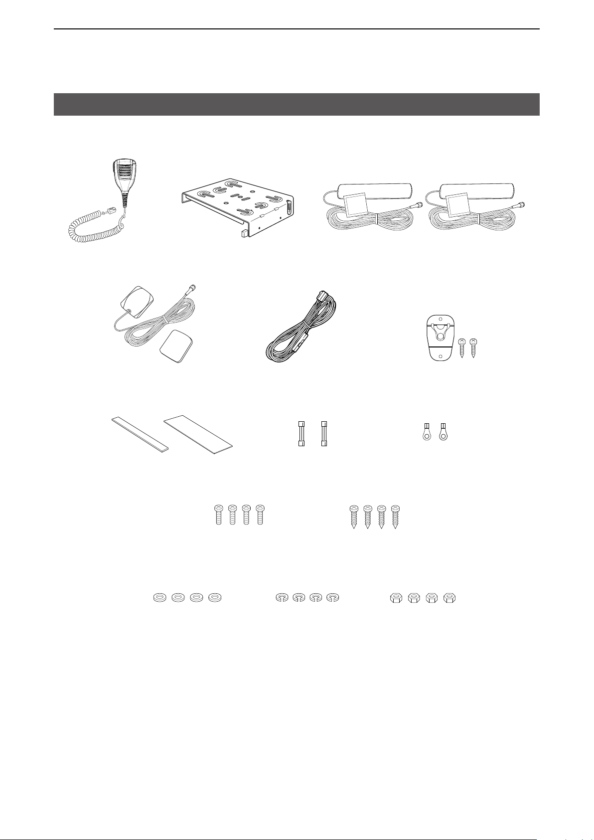
Supplied accessories
Speaker microphone
gPS antenna and
double-sided adhesive pad
Cushion and sheet for the
mounting bracket
Mounting bracket
DC power cable
Spare
fuses (5A)
LTe antennas (with cleaning cloth)
Microphone hanger
and screw set
Terminals for
DC power cable
(R2-6)
Mounting screws
(M5×12 mm)
Flat washers Spring washers nuts
Self-tapping screws
(M5×20 mm)
1-2
Page 5
1
BeFORe uSIng
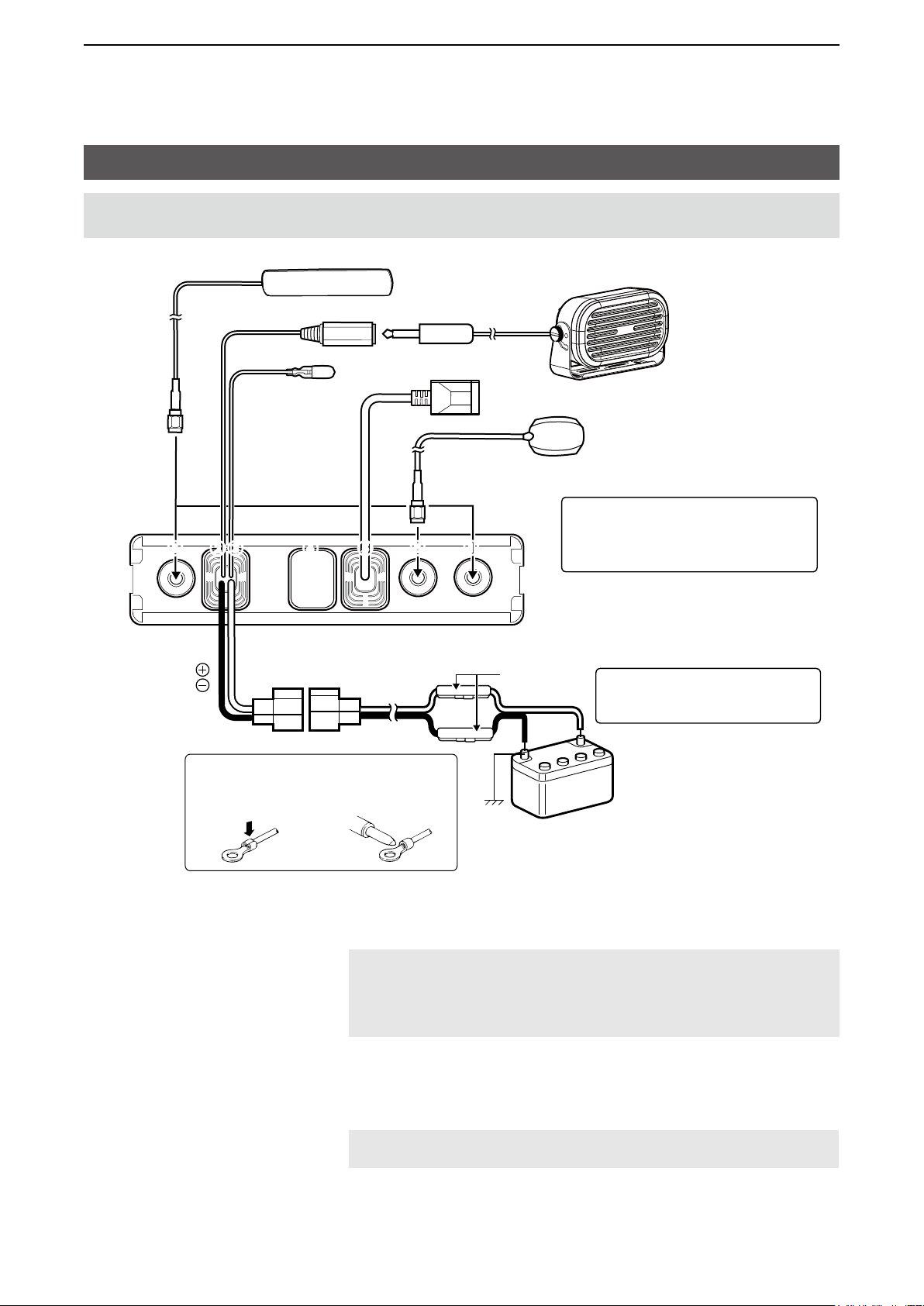
Rear panel connection
NOTE: Keep at a distance of 20 cm (8 inches) or more between the LTe antenna of this device and any
persons during operation.
Optional speaker
TIP: After connecting the LTe Antennas
and gPS Antenna, wrap the connectors
1 2 3 4 5 6
1
with rubber vulcanizing tape to help in
waterproofi ng.
7
Red
Black
NOTE: use the terminals as shown
below for the cable connections.
Crimp
Solder
Fuse holders
12 V or 24 V Battery
R WARNING! NEVER remove the
fuse holders from the DC power
cable.
1 L TE ANTENNA CONNECTORS Connect to the supplied LTe antenna. Contact your dealer about
antenna placement.
NOTE:
• Keep at a distance of 30 cm (12 inches) or more between the LTe antennas
during operation.
• Be sure the LTe antennas are positioned where they have a clear view to
receive signal, and fi xed using the adhesive pad.
2 EXTERNAL SPEAKER JACK Connect a 4 ~ 8 Ω external speaker.
3 IGNITION LEAD …………… Connect to an ignition line.
CAUTION: DO NOT put pressure on this lead. Binding to the DC
power cable is recommended.
4 D-Sub 25-pin ……………… Remove the cover and connect the optional OPC-2407 ACC CABLe.
1-3
Page 6
1
BeFORe uSIng
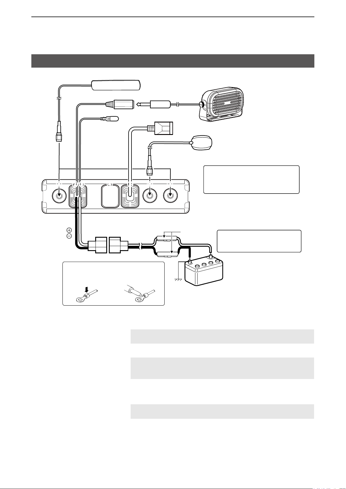
Rear panel connection
1 2 3 4 5 6
1
Optional speaker
TIP: After connecting the LTe Antennas
and gPS Antenna, wrap the connectors
with rubber vulcanizing tape to help in
waterproofi ng.
7
Red
Black
NOTE: use the terminals as shown
below for the cable connections.
Crimp
Solder
Fuse holders
12 V or 24 V Battery
R WARNING! NEVER remove the
fuse holders from the DC power
cable.
5 LAN CABLE ………………… Connect the network devices such as a switch.
CAUTION: DO NOT connect other than network devices, such as
microphone. This could damage the transceiver.
6 GPS ANTENNA CONNECTOR Connect the supplied gPS antenna.
NOTE: Be sure the gPS antenna is positioned where the gPS
antenna has a clear view to receive signal from satellites, and fi xed
using the supplied double-sided adhesive pad.
7 DC POWER CONNECTOR Connect to a 12 V or 24 V DC battery.
Pay attention to polarities. Red line: +, Black line: _
CAUTION: DO NOT reverse the DC power cable polarity when
connecting to a power source. This could damage the transceiver.
1-4
Page 7
1
BeFORe uSIng
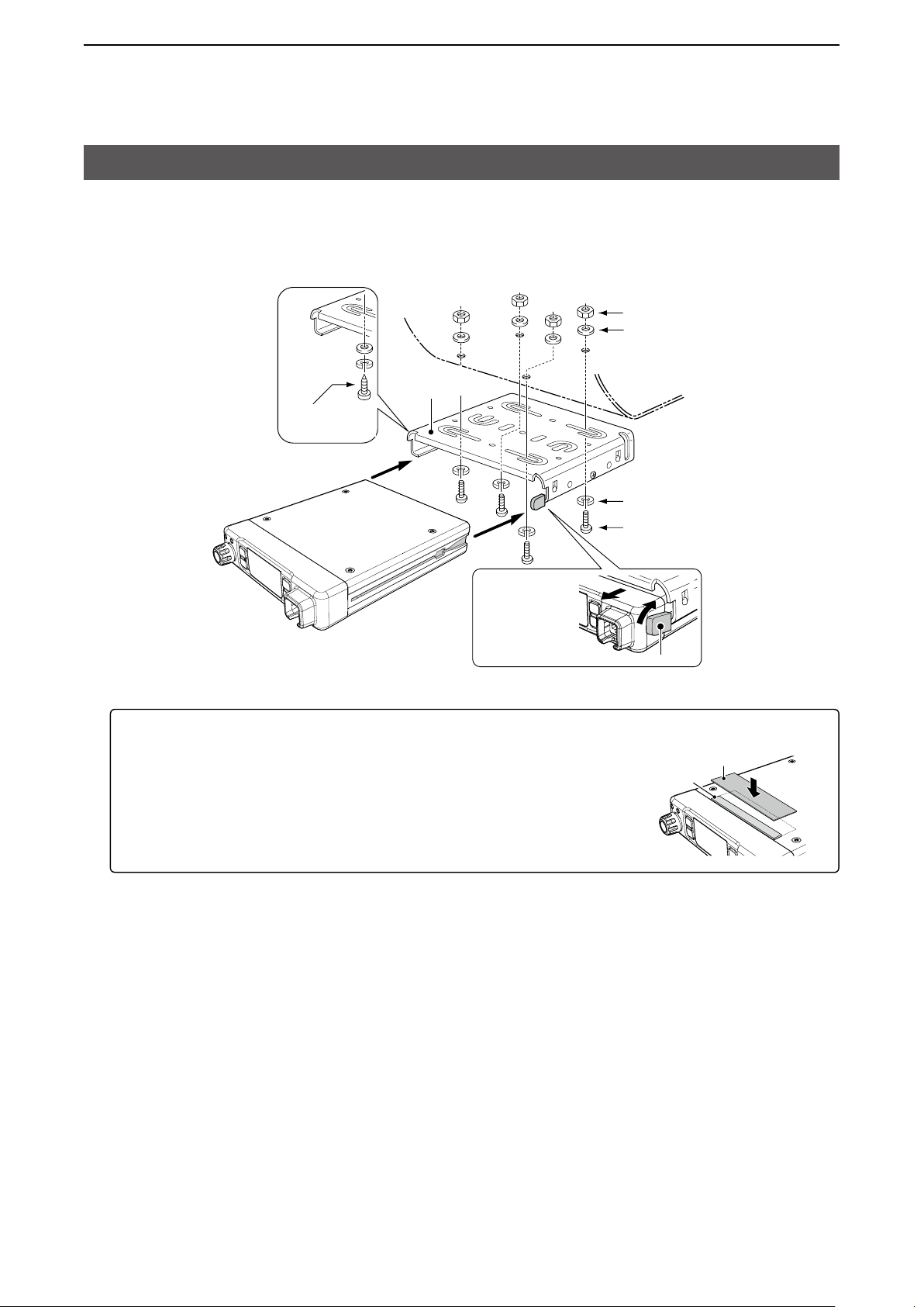
Mounting the transceiver
The universal mounting bracket supplied with your transceiver enables various mounting positions. Mount the
transceiver securely with the 4 supplied screws to a thick surface which can support more than 1.5 kg (3.3 lb).
nuts
Flat washers
Mounting
bracket
Self-tapping
screws
Spring washers
When
removing, slide
the transceiver
towards you
while push the
lever.
To reduce vibration, place the cushion on the transceiver and put the sheet on it.
L When mounting the bracket on the bottom side, attach a cushion and a sheet to
the bottom of the transceiver.
Mounting screws
Lever
Sheet
Cushion
1-5
Page 8
1
BeFORe uSIng
Panel Description
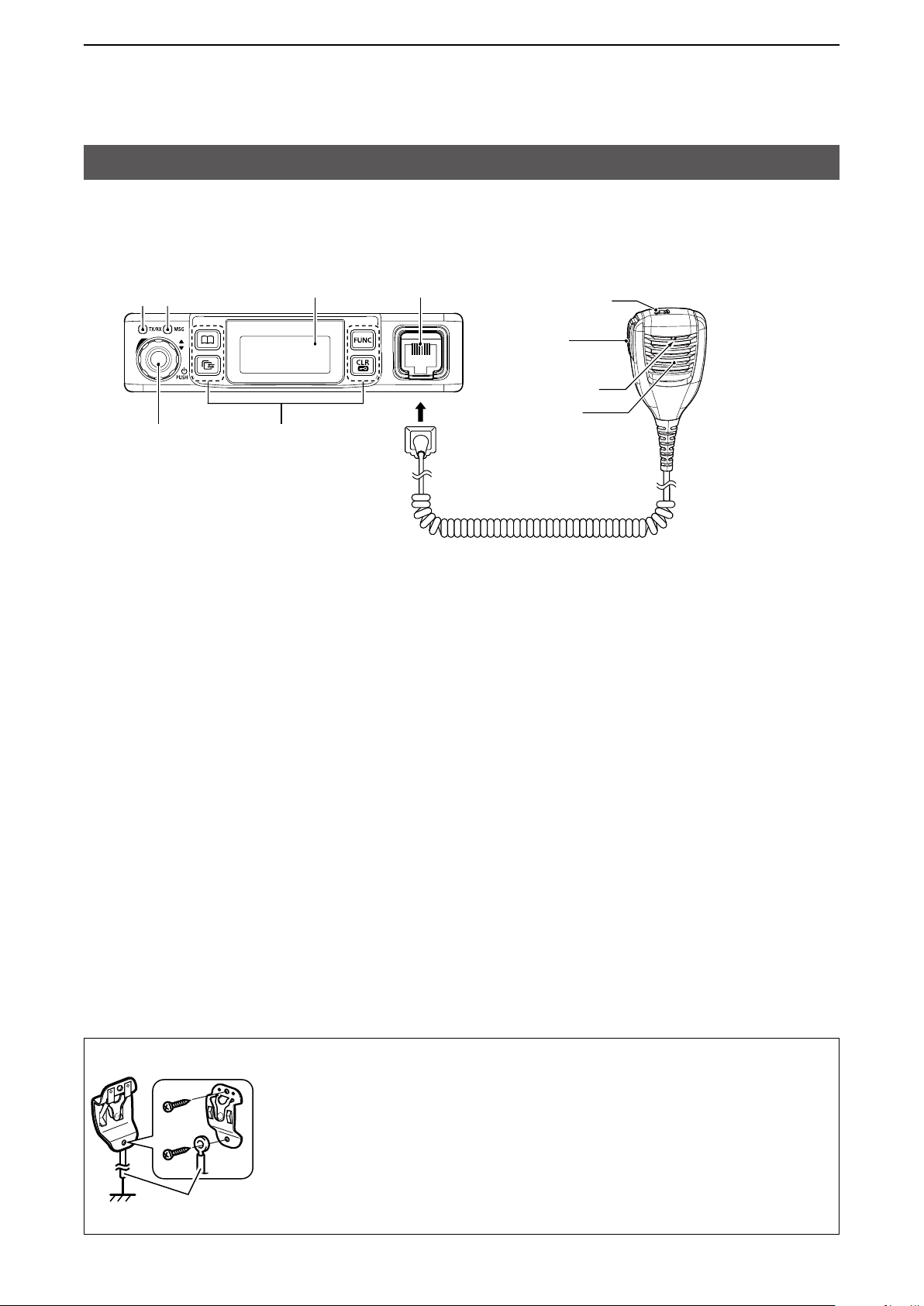
■ Front Panel
Indicators
[TX/RX] [MSg]
Function display
Microphone jack
Option key
IP501M
[DIAL] Operating keys
D DIAL
Hold down for 1 second to turn the transceiver On or OFF.
• On standby screen: Rotate to adjust the audio volume.
• Others: Rotate to select an item.
D Indicators
[TX/RX] Lights red: Transmitting
Lights green: Receiving
Lights orange: Receiving and transmitting
[MSG] Reserved for a future function.
[PTT]
Microphone
Speaker
D Speaker microphone
The speaker microphone works as shown below when you hang (On-hook) or remove (Off-hook) it to or from
the microphone hanger.
L The speaker microphone may works in a different way, depending on the presetting.
On-hook:
• end the call and return to standby screen.
Off-hook:
• When a call is received, remove the microphone to stop the receive tone.
• When the P-Bell function (p. 3-7) is enabled, remove the microphone to release the mute.
MICROPHONE HANGER
Connect the microphone hanger to the vehicle’s ground for microphone On/OFF hook
functions when the microphone is used.
user supplied
1-6
Page 9

1
BeFORe uSIng
Panel Description
D Operating keys
Assigned key functions may differ, depending on the presetting.
[Address] key
• Selects a preset address.
• Push to toggle the Address Book between the call types.
L You can also toggle the address by rotate [DIAL].
[Call History] key
• Push to display the call history.
• Push this key several times to toggle between the Call his types, Transmitted call, Received call, Sent
message, and Received message.
• Hold down until “emergency” is displayed to send an emergency call.
[FUNC] key
• Push to select a Message, Status, Talkgroup, Bluetooth Pairing, uTC Offset function, Bluetooth One Touch
PTT function, or network Operator.
• Hold down for 3 seconds to enter the Set Mode function.
[CLR/Lock] key
• Push to return to the standby screen.
• Hold down for 1 second to turn the Key Lock function On or OFF.
L [PTT] and [DIAL] are usable even while the Key Lock function is On.
All → Group (Talkgroup) → Individual
1-7
Page 10

1
BeFORe uSIng
Panel Description
■ Function Display
Standby screen
10/14 12:00
All
Scrolls, depending on the message length
Example: When receiving a
custom message
10/14 13:00
everyone meet
nOW
: Signal strength
The signal strength is represented by 3 bars.
L When the transceiver location is out of the service area, or cannot receive the control signal, the (out-of-area)
icon blinks.
L If the IP501M has not been authenticated,
is displayed.
: Call types
Shows the call type.
Blinks when a call or message is received.
: All/group Call
: Talkgroup Call*
: Individual Call
: Phone Call*
* May be usable, depending on a presetting.
: Bluetooth (p. 5-5 )
Displayed when the transceiver is connected to Bluetooth device.
: Pocket beep (p. 3-7)
• Displayed when the Pocket Beep function is On.
• Blinks when a call is received. This icon blinks until the transceiver return to the standby mode after a received signal
disappears.
: P-Bell (p. 3-7)
Displayed when the P-Bell function is used.
: Key Lock
Displayed when Key Lock function is On.
: GPS
• Displayed when valid position data is received.
• Blinks when searching for satellites or calculating position data.
1-8
Page 11

BASIC OPERATION
Basic operation ………………………………………………………………………………………………………… 2-2
MTurning the transceiver ON or OFF …………………………………………………………………………… 2-2
MReceiving and Transmitting …………………………………………………………………………………… 2-2
Using the Address book ……………………………………………………………………………………………… 2-3
DSelecting a call-to party from the Address book .......................................................................................2-3
DSelecting a call-to party from the Call history ...........................................................................................2-3
Section
2
2-1
Page 12
2
BASiC OpeRATiON
Basic operation
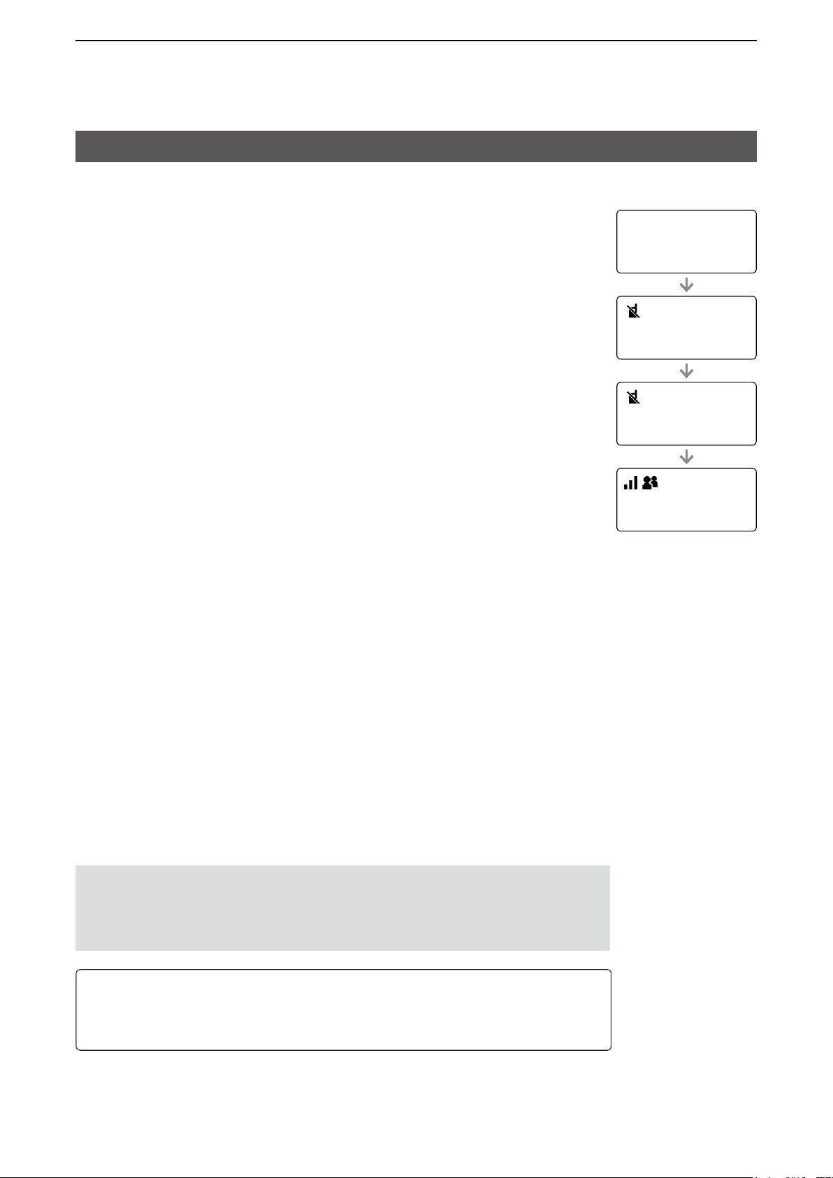
■ Turning the transceiver ON or OFF
Turning ON:
Hold down [DiAL] for 1 second to turn ON the transceiver.
• The standby screen is displayed as shown to the right.
L It may take a few minutes to boot up the transceiver for the fi rst time.
Turning OFF:
Hold down [DiAL] for 1 second to turn OFF the transceiver.
ip501M
Ver. x.x.xx/x
Connecting...
00002
Setting up...
00002
■ Receiving and Transmitting
Receiving:
When a Call is received, the [TX/RX] indicator lights green.
Rotate [DiAL] to adjust the audio output level to a comfortable listening level.
L When the volume is “0,” key beeps and ringer tones do not sound.
Transmitting:
While holding down [pTT], speak at your normal voice level.
• The [TX/RX] indicator lights red while [pTT] is pushed.
Talk while receiving a call:
While receiving a call, push [pTT] to talk in the Full-Duplex mode* like a telephone call.
• in the Full-Duplex mode, the [TX/RX] indicator lights orange.
L Rotate [DiAL] to adjust the audio output level.
DO NOT cover the speaker or microphone.
* Depends on a presetting. Ask your dealer for details.
IMPORTANT:
To maximize the readability of your signal:
1. After pushing [pTT], pause briefly before you start speaking.
2. Hold the microphone 5 ~ 10 cm (2 ~ 4 inches) from your mouth, then speak at
your normal voice level.
10/14 12:00
All
About the Time-out Timer:
When the continuous transmission period exceeds 5 minutes, the Time-out Timer
automatically stops the transmission to prevent prolong transmissions. Release the
[pTT], then hold down again to resume talking.
2-2
Page 13

2
BASiC OpeRATiON
Using the Address book
You can select a call-to party from the Address book or Call history.
D Selecting a call-to party from the Address book
The [Address] key can be used, depending on a preset. Ask your dealer for details.
About the call type:
All call: Transmit to all of the transceivers that belongs to the network.
Group call: Transmit to the transceivers that belongs to the same group.
Talkgroup call: See page 3-4 for details.
individual call: Transmit to an individual transceiver.
Telephone call: Transmit to an ip phone.*
*Transmittable, depending on the presetting.
1. push [Address] to display the Address book.
• The Address book is displayed.
2. push [Address] several times to toggle the call type.
L Displayed call type may differ, depending on the presetting.
All → Group → Individual → Telephone
Group
10001
Sales 1
3. Rotate [DiAL] to select a call-to party.
4. While holding down [pTT], speak at your normal voice level.
D Selecting a call-to party from the Call history
The transceiver’s each Call history stores a maximum of 10 logs.
1. push [Call History] to display the Call history.
• The Call history is displayed.
2. push [Call History] several times to toggle the log.
L Displayed log may differ, depending on the presetting.
Tx log → Rx log → Tx MSG log → Rx MSG log → Tx Call log → Rx Call log
3. Rotate [DiAL] to select a call-to party.
4. While holding down [pTT], speak at your normal voice level.
NOTE: You can delete logs in the Set mode. See page 4-3 for details.
Rx log
10/3 13:37
Sales 8
2-3
Page 14

ADVANCED OPERATION
Sending a message (Message Call) ………………………………………………………………………………… 3-2
MSelecting a call-to party ………………………………………………………………………………………… 3-2
MSending a message …………………………………………………………………………………………… 3-2
DSending a preset message .......................................................................................................................3-2
DCreating and sending a message using the optional HM-230HB.............................................................3-2
Browsing received messages………………………………………………………………………………………… 3-3
Status Call ……………………………………………………………………………………………………………… 3-3
Searching the ID List using the optional HM-230HB ……………………………………………………………… 3-3
About the Talkgroup Call ……………………………………………………………………………………………… 3-4
DSelecting a Talkgroup number ..................................................................................................................3-5
Emergency Call function ……………………………………………………………………………………………… 3-6
Section
3
Other functions ………………………………………………………………………………………………………… 3-7
DPocket Beep function ...............................................................................................................................3-7
DP-Bell function ..........................................................................................................................................3-7
DLone Worker function ...............................................................................................................................3-7
3-1
Page 15

3
ADvAnCED OPErATIOn
Sending a message (Message Call)
You can send a message, depending on a presetting. Ask your dealer for details.
■ Selecting a call-to party
1. Push [Address] to display the Address book.
• The Address book is displayed.
2. Push [Address] several times to toggle the call type.
L Displayed call type may differ, depending on the presetting.
All → Group → Individual → Telephone
3. rotate [DIAL] to select a call-to party.
TIP: You can select a call-to party also from Call history.
1. Push [Call History] to display the Call history.
• The Call history is displayed.
2. Push [Call History] several times to toggle the Call history from “Tx log,” “rx
log,” or “TX MSG log.”
L Displayed log may differ, depending on the presetting.
Tx log → Rx log → Tx MSG log → Rx MSG log → Tx Call log → Rx Call log
Individual
00002
Sales2
3. rotate [DIAL] to select a call-to party.
■ Sending a message
D Sending a preset message
1. Push [FUnC] to display the Function.
• The Function is displayed.
2. Push [FUnC] to display “Message,” if the other function is displayed.
L May be required to push [FUnC] several times, depending on the presetting.
3. rotate [DIAL] to select a message to send.
• The selected message may scroll, depending on the message length.
4. Push [PTT] to send a message.
L “no response” is displayed if the transmission failed.
D Creating and sending a message using the optional HM-230HB
You can create and send a message, depending on the presetting.
L An optional HM-230HB command microphone (p. 5-3) is required.
1. Push an Option key that is assigned as a shortcut to the “Create Message.”
Message
Sales2
Gather immediately
10/4 12:57
Successful
Create Message
ABC
2. Create a message using the keypad.
TIP:
• Push [FUnC] to change the entry mode (“ABC” or “123”).
• Push [◄] or [►] move the cursor.
• Push [▲] or [▼] to select a preset message to insert.
• Push [CLr/Lock] to delete an entered character.
• Hold down [CLr/Lock] to delete all characters.
3. Push [PTT] to send a message.
Create Message
COME TO 3F
ABC
3-2
Page 16

3
ADvAnCED OPErATIOn
Browsing received messages
You can browse received messages, depending on the presetting. Ask your dealer for details.
1. Push [Call History] to display the Call history.
• The Call history is displayed.
2. Push [Call History] to display “Rx MSG log.”
L May be required to push [Call History] several times, depending on the presetting.
3. rotate [DIAL] to browse received messages.
L The selected message may scroll, depending on the message length.
10/4 12:57
All Gather immed
Status Call
You can send a Status call depending on a presetting. Ask your dealer for details.
Rx MSG log
1. Push [FUnC] to display the Function.
• The Function is displayed.
2. Push [FUnC] to display “Status,” if the other function is displayed.
L May be required to push [FUnC] several times, depending on the presetting.
3. rotate [DIAL] to select a status.
4. Push [PTT] to send a status.
At meeting
Status
Searching the ID List using the optional HM-230HB
You can search an ID in the Address book, depending on the presetting. Ask your dealer for details.
L An optional HM-230HB command microphone (p. 5-3) is required.
1. Push [Address] to display “Search ID List.”
2. Enter an ID using the keypad.
TIP:
• Push [FUnC] to change the entry mode (“ABC” or “123”).
• Push [◄] or [►] move the cursor.
• Push [CLr/Lock] to delete an entered character.
• Hold down [CLr/Lock] to delete all characters.
Search ID List
A
ABC
3. Push [▲] or [▼] to display and select the found ID list.
3-3
Search ID List
00011
A-01
Page 17

3
ADvAnCED OPErATIOn
About the Talkgroup Call
The Talkgroup Call function enables the user to communicate with call-to parties in the same Talkgroup.
For example, in the illustration below, when IP501M “00004” in its normal group “10001” selects Talkgroup
“20001,” it is excluded from group “10001,” and can communicate with only IP501Ms “00006” and “00008” that
belong to the Talkgroup “20001.”
L This function can be used for only when the Talkgroup number is registered, and the Talkgroup Call function is assigned
to a key by your dealer.
L Ask your dealer about whether or not to include the Talkgroup in the All Call.
When Talkgroup is OFF
Group 10001 Group 10002
00001 00002 00003 00004 00005 00006 00007 00008
Talkroup 20001 Talkroup 20002
All
When Talkgroup is selected
Group 10001 Group 10002
00001 00002 00003 00005 00007
Talkroup 20001 Talkroup 20002
00004 00008
00006
All
3-4
Page 18

3
ADvAnCED OPErATIOn
About the Talkgroup Call
D Selecting a Talkgroup number
You can select a Talkgroup number if the Talkgroup Call function is assigned to the [FUnC] or [Address] key.
Ask your dealer for details.
Selecting with a [FUNC] key:
1. Push [FUnC] to display the Function.
• The Function is displayed.
2. Push [FUnC] to display “Talkgroup,” if the other function is displayed.
L May be required to push [FUnC] several times, depending on the presetting.
3. rotate [DIAL] to select a Talkgroup number that you want to belong.
4. Push [CLr/Lock].
• The transceiver is ready to talk to only the transceivers that belong to the same
Talkgroup.
L While the Talkgroup number is selected, you cannot transmit Normal Group call.
L You can leave the Talkgroup and return to the Normal Group by selecting “OFF”
in Step 2 on the “Talkgroup” screen.
Talkgroup
20001
Talkgroup 1
10/4 12:57
Talkgroup 1
Selecting with a [Address] key:
1. Push [Address] to display the Address book.
• The Address book is displayed.
2. Push [Address] several times to display “Group” or “Talkgroup.”
3. rotate [DIAL] to select a Talkgroup number that you want to belong.
4. Push [CLr/Lock].
• The transceiver is ready to talk to only the transceivers that belong to the same
Talkgroup.
L While the Talkgroup number is selected, you cannot transmit Normal Group call.
L You can leave the Talkgroup and return to the Normal Group by selecting “OFF”
in Step 2 on the “Talkgroup” screen.
Talkgroup
20001
Talkgroup 1
10/4 12:57
Talkgroup 1
3-5
Page 19

3
ADvAnCED OPErATIOn
Emergency Call function
You can receive or transmit Emergency Call if the function is assigned to the Option key or [Call History] key.
Ask your dealer for details.
Transmitting:
L The instruction is based on the case that the function is assigned to the Option key.
1. Hold down the Option key until “Emergency” is displayed.
• An alarm sounds periodically.
L If the Silent mode is enabled by your dealer, no alarm sounds, and no emergency
indication is displayed.
2. Wait for the answer-back.
• When the transceiver receives an answer-back, the alarm stops, and the [TX/rX] indicator
lights green.
L To cancel the emergency call, hold down the Option key until “Emergency” disappears, or
turn OFF the transceiver.
Receiving:
1. “Emergency” is displayed and the alarm periodically sounds.
L When the Silent mode is enabled by your dealer, no alarm sounds.
2. While holding down [PTT], talk into the microphone.
• While holding down [PTT], the [TX/rX] indicator lights red.
• The alarm stops.
• returns to the Standby screen when you release [PTT].
Emergency
Sales2
Emergency
Sales1
NOTE: The Emergency function may not properly work, depending on the
surrounding environment such as obstructions, weather condition, and so on.
Icom is not responsible for the destruction or damage caused by using the Emergency
Call function.
3-6
Page 20

3
ADvAnCED OPErATIOn
Other functions
D Pocket Beep function
The Pocket beep function sounds a notication tone and indication when a call is received.
L This function is set by your dealer, or in the Set mode.
L “
” is displayed when the function is On.
L “
” blinks and the notification beep sounds when a call is received. It blinks until the transceiver return to the standby
mode after a received signal disappears.
D P-Bell function
The P-Bell function sounds the notication tone when a call is received.
A received call is muted until you reply. After pushing [PTT], the mute is released.
L This function is set by your dealer, or in the Set mode.
L “
” is displayed when the function is On.
D Lone Worker function
When the Lone Worker function is activated, the Emergency Call function (p. 3-6) is automatically turned On
after the transceiver has been left without any operation for the specied period of time.
NOTE: The Lone Worker function may not properly work, depending on the surrounding environment such as
obstructions, weather condition, and so on.
Icom is not responsible for the destruction or damage caused by using the Lone Worker function.
3-7
Page 21

SET MODE
Using the Set mode …………………………………………………………………………………………………… 4-2
DBasic Set mode ........................................................................................................................................4-2
DDetailed Set mode ....................................................................................................................................4-2
DUsing the Set mode ..................................................................................................................................4-2
Set mode items ………………………………………………………………………………………………………… 4-3
Section
4
4-1
Page 22

4
Set moDe
Using the Set mode
You can use the Set mode to set infrequently changed values or function settings.
the transceiver has 2 types of Set mode, as shown below.
L You cannot transmit or receive while the transceiver is in the Set mode.
D Basic Set mode
z Hold down [FUNC] for 3 seconds to enter the Set mode.
• “Set” is displayed.
D Detailed Set mode
1. Hold down [FUNC] for 3 seconds to enter the Set mode.
• “Set” is displayed.
2. Hold down [FUNC] for 3 seconds again to enter the Detailed Set mode.
• “Set (Detail)” is displayed.
Set
LoG
– – –
Set(Detail)
LoG
– – –
D Using the Set mode
1. Push [FUNC] or [Address] to select an item.
2. Rotate [DIAL] to select an option.
L Pushing [Call History] may be required to apply the selected option.
See page 4-3 to 4-6 for details.
3. Push [Ptt] or [CLR/Lock] to exit the Set mode.
4-2
Page 23

4
Set moDe
Set mode items
the shaded items are also displayed in the Basic Set mode.
L Items or default values may be different, depending on the transceiverʼs version or presettings. Ask your dealer for
details.
Item Description Option/range Default
LoG Deletes logs.
L Select “CLR,” and then push [Call History] to delete.
ReSet Resets the transceiver to its defaults, except for
the Bluetooth pairing list.
L Select “YeS,” and then push [Call History] to reset.
L the transceiver automatically restarts.
FIRm UP Updates the transceiverʼs rmware.
L Select “YeS,” and then push [Call History] to reset.
L the transceiver automatically restarts.
L Updating the rmware takes approximately 10
minutes.
Success tone Selects whether or not to enable the tone that
indicates an individual call was successfully
transmitted.
L the transmission result is also displayed on the
screen.
Failure tone Selects whether or not to enable the tone that
indicates an individual call failed.
L the transmission result is also displayed on the
screen.
Call tone
(IND/GRP/ALL/
teL)
Crtsy Beep
(IND/GRP/ALL/
teL)
RX tone
(IND/GRP/ALL/
teL/mSG)
Notify type
(IND/GRP/ALL/
teL)
Sets the Call Initiation tone. Disable, tone1 ~ tone8
Sets the Call termination beep. Disable, tone1 ~ tone8
Sets the Call Receive tone. Disable, tone1 ~ tone8
Sets the call receive notication type. P-Bell or Pocket beep P-Bell
– – –, CLR – – –
No or YeS No
No or YeS No
enable or Disable enable
enable or Disable enable
tone1 (Pi)
L Larger number makes
the tone lower.
tone1 (Pi)
L Larger number makes
the beep lower.
Disable
L Larger number makes
the tone lower.
Notify No.
(IND/GRP/ALL/
teL/mSG)
RX Notify Vol. Sets the call or message received notication
out of Rng tone Selects whether or not to enable the out-of-Area
VoX Selects a VoX function option.
Sets the number of tones. Continuous (except for
volume.
Warning Beep. the beep also sounds when the
transceiver reenters the service area.
(out-of-area: “Pipi,” Reenters: “Popo”)
the function automatically switches between
receive and transmit by detecting your voice.
4-3
3 (times)
“MSG”), 1, 3, 10, 20
(times)
0 ~ 32 10
Disable or enable Disable
Disable, Bluetooth mic Disable
Page 24

4
Set moDe
Set mode items
the shaded items are also displayed in the Basic Set mode.
L Items or default values may be different, depending on the transceiverʼs version or presettings. Ask your dealer for
details.
Item Description Option/range Default
VoX threshold Sets the VoX threshold level.
L Lower values make the VoX function more sensitive
to your voice.
echo Canceller Selects whether or not to enable the echo
Cancelling function.
L Commonly used for an earphone mIC, and headset.
Noise Canceller Selects whether or not to enable the Noise
Cancelling function.
L Commonly used for a transceiver, earphone mIC,
and headset.
BackLight Selects a Backlight option. Auto (Key), oN, oFF,
0% ~ 100% 40%
enable or Disable enable
enable or Disable enable
oN
Dim, Auto (Dim)
BackLight mIC Selects an HM-230HBʼs Backlight option.
L Displayed only when an optional HM-230HB is
attached.
Auto (Key), oN, or oFF Auto (Key)
Contrast Sets the screen contrast. 1 (lowest) ~ 16 (highest) 8
Contrast mic Sets the HM-230HBʼs screen contrast.
L Displayed only when an optional HM-230HB is
attached.
Dimmer mic Sets the HM-230HBʼs dimmer level.
L Displayed only when an optional HM-230HB is
attached.
mic Gain Sets the microphone sensitivity.
L Higher values make the microphone more sensitive
to your voice.
1 (lowest) ~ 16 (highest) 8
0 (lowest) ~ 31 (highest) 31
–12 dB (lowest) ~ 12 dB
0 dB
(highest) (in 3 dB step)
Notify Beep Vol. Sets the Notication Beep level. 0 ~ 32 10
Key-touch Beep Selects whether or not to enable the Key-touch
enable or Disable enable
beep.
Key Beep Vol. Sets the Key-touch beep level. 0 ~ 32 10
RX Buffer type Sets the Jitter buffer size.
L Jitter buffer reduces audio interruptions.
Dynamic,
40 ~ 480 milliseconds
Dynamic
(in 40 milliseconds step)
Call type Stnby Selects whether or not to display the call-to party
3
(Call type)*
*3Preset by your dealer.
on the standby screen.
Destination ID Selects a Destination ID display option.
L If “Disable” is selected, the call-to party (call type)
that is preset by your dealer is displayed on the
standby screen.
Bluetooth Selects whether or not to enable the Bluetooth
enable or Disable enable
Disable, All operations,
Disable
transmit and Receive, or
transmit
Disable or enable Disable
function.
4-4
Page 25

4
Set moDe
Set mode items
the shaded items are also displayed in the Basic Set mode.
L Items or default values may be different, depending on the transceiverʼs version or presettings. Ask your dealer for
details.
Item Description Option/range Default
Bt Auto Connect*1Selects whether or not to automatically connect a
Bluetooth device.
1
Bt Sync Vol.*
Selects whether or not to synchronize the Bluetooth
headsetʼs volume level with the transceiverʼs
volume level.
L When “Enableˮ is selected, the Bluetooth headset
volume can be set by rotating [DIAL].
Bt Connect
1
type*
Selects the Synchronous Connection-oriented
(SCo) link*4 connection type of a Bluetooth
headset.
When “Auto Disconnect” is selected, the SCo link
is automatically disconnected after 2 seconds.
*4A Bluetooth link for voice communication.
L this setting is valid only when a Bluetooth device
other than a VS-3 is used.
L When this item is set to “Auto Disconnect,” the VoX
function is not usable.
Ptt & mic
Switch*
1
Bt AF output*
enables the user to select which microphone to
use.
L When this item is set to “Auto,” transmits the audio
from the device whose [Ptt] is pushed.
1
Selects the AF output device when a Bluetooth
headset is connected.
enable or Disable enable
Disable or enable Disable
Always Connect or Auto
Disconnect
Auto, Bluetooth mic, or
Always
Connect
Auto
Radio mic
Bt only, Bt & SP Bt only
Bt echo
Canceller*
1
Bt e-Cancel
1
Gain*
Bt e-Cancel
1
Delay*
Bt Noise Cancel*
Selects whether or not to enable the Bluetooth
headsetʼs Echo Canceller.
Sets the echo Canceller input gain for a Bluetooth
headset.
Sets the echo Canceller delay for a Bluetooth
headset.
1
Selects whether or not to enable the Bluetooth
headsetʼs Noise Canceller.
1
Bt Power Save*
Selects whether or not to enable the Bluetooth
headsetʼs Power Save function.
L When “Enableˮ is selected, the Power Save function
automatically activates after 2 minutes of no
communication.
*1Displayed only when “enable” is selected in the “Bluetooth” item.
enable or Disable enable
–40 dB ~ +40 dB 0 dB
0milliseconds ~
160milliseconds
35milli-
seconds
enable or Disable enable
Disable or enable Disable
4-5
Page 26

4
Set moDe
Set mode items
the shaded items are also displayed in the Basic Set mode.
L Items or default values may be different, depending on the transceiverʼs version or presettings. Ask your dealer for
details.
Item Description Option/range Default
Bt one touch
1
Ptt*
Show Bt one
touch Ptt*
1
Bt Ptt Beep*
Selects whether or not to enable the one-touch Ptt
function while a Bluetooth headset is connected.
the function toggles receiving and transmitting by
momentarily pushing [Ptt] on a Bluetooth headset.
L Push [Ptt] to talk, and push again to return to
receive.
L When "enable" is selected, you do not have to hold
down [Ptt] while you are talking.
Selects whether or not to display the “Bt one
Touch PTTˮ item by pushing [FUNC] on the standby
screen.
1
Selects whether or not to sound a beep when the
[Ptt] on the Bluetooth headset is pushed.
Disable or enable Disable
Disable or enable Disable
Disable or enable Disable
Search Bt
Device*
1
Delete Bt
Device*
1
Init Bt Unit*
Searches for Bluetooth devices.
L Push [Call History] to start searching.
Deletes paired devices. – –
1
Initializes the built-in Bluetooth unit and pairing list. No or YeS No
Search –
Bt Unit Version Displays the built-in Bluetooth unit version. – –
Horn (ext. I/o)*
ID List Select
mode (ext. I/o)*
Selects whether or not to enable the external horn
that connected to
an optional OPC-2407 acc cable.
Selects whether or not to enable selecting a talk-
2
to-party from an external device connected to an
Disable or enable Disable
Disable or enable Disable
2
optional OPC-2407 acc cable.
UtC offset*
Daylight Sav
3
time*
Show SIm
Selection
3
Set the offset time between the UtC (Universal
time Coordinated) and local time.
Selects whether or not to use Daylight Saving
time (DSt) for the clock.
Selects whether or not to display the “SIm
Selectionˮ item by pushing [FUNC] on the standby
–14:00 ~ +14:00
(in 1 minute steps)
Disable or enable Disable
Disable or enable Disable
screen.
SIm Selection Selects a SIm card.
L Rotate [DIAL] to select a SIm card, and then push
[Call History] to restart the transceiver.
_ _ _*5 (SIm1)
* 5A SIm card name is
displayed, if it is named.
00:00
_ _ _ (SIm1)
*1Displayed only when “enable” is selected in the “Bluetooth” item.
2
*
Displayed only when the function is assigned to the OPC-2407ʼs D-sub 25 pin by your dealer.
3
*
Displayed only when the transceiver uses the SNtP server for clock synchronization.
4-6
Page 27

4
Set moDe
Set mode items
the shaded items are also displayed in the Basic Set mode.
L Items or default values may be different, depending on the transceiverʼs version or presettings. Ask your dealer for
details.
Item Description Option/range Default
Show Network
Select
Network Select Selects whether or not to automatically select a
Network Search Searches for a network carrier.
HM-230 Version Displays an optional HM-230HBʼs rmware
Lte Unit Version Displays the internal Lte unit version. – –
ImeI Displays the Communication unitʼs IMEI number. – –
Phone Number Displays the SIm card’s telephone number. – –
ICCID Displays the SIm card’s ICCID. – –
Selects whether or not to display the “Network
Selectˮ item by pushing [FUNC] on the standby
screen.
network carrier.
L Displayed only when “User select” is selected in the
“Network Select” item.
version, if it is connected.
Disable or enable Disable
Auto, Last accessed, or
User select
Search –
– –
Auto
4-7
Page 28

OPTIONS
Options ………………………………………………………………………………………………………………… 5-2
Using the HM-230HB command microphone ……………………………………………………………………… 5-3
MConnecting the HM-230HB …………………………………………………………………………………… 5-3
MPanel description ………………………………………………………………………………………………… 5-3
Using the Bluetooth
MAbout the VS-3 Bluetooth headset …………………………………………………………………………… 5-4
MPairing with a Bluetooth device ………………………………………………………………………………… 5-5
MSettings for the Bluetooth function …………………………………………………………………………… 5-5
MDisconnecting the paired device ……………………………………………………………………………… 5-6
MDeleting a device from the Pairing list ……………………………………………………………………… 5-6
MInitializing the Pairing lists ……………………………………………………………………………………… 5-7
®
device ………………………………………………………………………………………… 5-4
Section
5
5-1
Page 29

5
OPTIONS
Options
L Some options may not be available in all countries. Ask your dealer for details.
Microphones
• HM-230HB
• HM-241 speaker microphone
Same as supplied
• SM-28 desktop microphone
• VS-3
The Bluetooth headset with a [PTT] switch.
• About third-party Bluetooth headsets:
Icom has checked the PTT operation with some
3M Peltor headsets such as the WS Headset XP,
WS ProTac XP and WS Alert XP.
(Compatibility not guaranteed)
command microphone
Bluetooth
®
headset
Headsets
External speakers
(Input impedence: 4 Ω)
• SP-30
Rated input 20 W,
Maximum input 30 W,
Cable length: Approximately 2.8 m (9.2 feet)
• SP-35 external speaker
Rated input 5 W,
Maximum input 7 W,
Cable length: Approximately 2 m (6.5 feet)
• OPC-2355
Extension cable for the microphone
Cable length: Approximately 2.5 m
• OPC-1122U programming cable
• OPC-2407 acc cable
D-sub 25-pin type
external speaker
Cables
extension cable
5-2
Page 30

5
OPTIONS
Using the optional HM-230HB command microphone
You can use the transceiver more comfortable using the HM-230HB command microphone.
■ Connecting the HM-230HB
Turn OFF the transceiver, and insert the HM-230HB connector into the microphone jack until it locks.
Turn OFF
Microphone jack
IP501M
■ Panel description
Option key
[Emergency]
Microphone
Option key [P1]
[PTT] switch
Option key [P2]
Option key [P3]
[VOL] control
[TX/RX] indicator
Function display
Operating keys
Cursor pad
Ten-key
Speaker
[TX/RX] indicator
• Lights red: Transmitting
• Lights green: Receiving a signal, or the squelch
is open
• Lights orange: Transmitting and receiving
in the full-duplex mode
Operating keys
The [Address], [Call History], [FUNC], and [CLR/
Lock] keys on the HM-230HB work as the same as
the keys on the transceiver (p. 1-7).
L Use the cursor pad to move the cursor or select an item.
Cursor pad
You can make a selection with the cursor pad in the
menu, Address, Call History, Set mode, and so on.
• Push [◄] or [►] to select an item, and push [▲] or [▼]
to select an option.
Option keys [Emergency], [P1] ~ [P3]
A dealer can assign the Software Key functions to
the Option keys (p.5-4).
Ten-key
L The usable functions differ, depending on the
presetting. Ask your dealer for details.
You can enter a message or select an address to
make a call. (p. 3-2)
Hold down the address number to directly select a
call-to-party from the Address Book.
L To select an address number with more than 2 digits,
push tens/hundreds place number, and then hold down
ones place number.
5-3
Page 31

5
OPTIONS
Using the optional HM-230HB command microphone
■ Using Option keys
The function shown below may be usable by using Option keys, depending on the presetting.
Ask your dealer for details.
Option key
[Emergency]
Option key [P1]
Option key [P2]
Option key [P3]
Function Description
Message Push an Option key to display the “Message.”
You can select a preset message to send.
L Push [▲] or [▼] to select a message.
Edit Message Push an Option key to display the “Create Message.”
You can create and send a message (p. 3-2).
One Touch Push an Option key to directly select a preset Call
type and call-to-party.
Clear Down Push an Option key to terminate the phone call with
an IP phone.
L Push before the target telephone is picked up, or during
a phone call.
L The transceiver can terminate the phone call when a
telephone calls the transceiver individually, or when the
transceiver calls a telephone.
Mute Hold down an Option key for 1 second to mute or
unmute the received audio.
L The Notication beep will not be muted.
L You can also unmute the received audio by pushing
[PTT].
Direct Dial Push an Option key to display the Direct Dial screen.
You can enter the destination ID or phone number by
using Ten-key.
Emergency Hold down an Option key until “Emergency” is
displayed to send an Emergency call (p. 3-6).
Horn (Ext. I/O) Push an Option key to turn the Horn function ON or
OFF.
L An external horn is required.
ID List Select
Mode
(Ext. I/O)
Push an Option key to turn the External ID List Select
function ON or OFF.
When the function is ON, a call type and a destination
ID or phone number is selected by only an external
input operation.
L The function is usable when an external unit is connected
to the transceiver.
5-4
Page 32

5
OPTIONS
Using a Bluetooth® device
You can connect to a Bluetooth device with built-in Bluetooth wireless technology.
L Only the VS-3 headset performance is guaranteed as of August 2019.
• The Bluetooth function may not be usable, depending on the presetting. Ask your dealer for details.
• The communication range of Bluetooth is approximately 10 m (33 ft).
L May vary, depending on the environment in which the device operates.
• Although you can enter up to 6 Bluetooth devices in the transceiver device list, it is recommended that you
pair only one device at a time.
Electromagnetic Interference
When you use a Bluetooth device, pay attention to the following:
Bluetooth devices operate in the 2.4 GHz band that is also used by
other appliances, such as Wireless LAN products, microwave ovens,
RFID systems, amateur radio stations, and so on.
When using a Bluetooth device near such devices, interference may
occur, causing a decrease in communication speed, and an unstable
connection.
In such case, keep the Bluetooth devices away from the other
appliances, or stop using those devices.
Bringing the Bluetooth device and the transceiver closer together also
improves communication.
■ About the VS-3 Bluetooth headset
When you connect an optional VS-3 Bluetooth headset to
the transceiver, you can wirelessly transmit and receive the
headset audio.
The VS-3 has a [PTT] switch, so you can transmit in the same
way as using the transceiver’s [PTT] switch.
• The [FWD], [RWD], and [PLAY] keys on the VS-3 are
disabled while using the headset with the IP501M.
• If the headset does not work correctly, even if the power is
ON, push [RESET] with a pin to force power OFF.
Microphone
Bluetooth headset
(Example: Optional VS-3)
IP501M
[PTT]
[VOL] (+)
[VOL] (–)
[PWR]
Bluetooth
Indicator
[RESET]
®
R
L
Function
Bluetooth
function
Pairing
mode
Transmit*
Audio
volume
1
: Functional only when a Bluetooth device is connected.
*
2
*
: Depends on the Notice Tone settings or “BT PTT Beep” setting in the Set mode.
ON
OFF Melody (down) OFF
Searching
Connected PiRo Blinks blue twice, every 3 seconds
1
1
Up*
1
Down*
Hold down [PWR] for 3 seconds
While Bluetooth function is OFF,
hold down [PWR] for 6 seconds
Push [PTT] Pi*
Push [VOL] (+) Pi –
Push [VOL] (–) Boo –
Operation Beep tone Indicator
Melody (up) Blinks blue
PiPa(ready to connect)
2
5-5
Charging port
Quickly blinks red then blue, every 3
seconds
Blinks red once, then blue twice, every
3 seconds
Page 33

5
OPTIONS
Using the Bluetooth® device
■ Pairing with a Bluetooth device
This is an example of connecting the transceiver to a VS-3 Bluetooth headset.
Turning ON the transceiver’s Bluetooth function
1.
1. Hold down [FUNC] for 3 seconds to enter the Set mode.
2. Push [FUNC] or [Address] several times to select “Bluetooth.”
3. Rotate [DIAL] to select “Enable,” and then push [Call History] to turn ON the
Bluetooth function.
2. Entering the VS-3 Pairing mode
1. Confirm the VS-3 is turned OFF.
2. Hold down [PWR] for 6 seconds.
• The indicator quickly blinks red then blue, and then the headset enters the
Pairing mode.
SET
Bluetooth
Enable
NOTE:
• Charge the VS-3 before operating.
• The VS-3 starts up in the Pairing mode when its Bluetooth function
is ON, but no bluetooth device is entered in its Pairing list.
3. Pairing and connecting the Bluetooth device
1. On the transceiver, select “Search BT Device” in the Set mode, and then push
[Call History].
• The transceiver searches for a Bluetooth device.
L Push [CLR/Lock] to cancel searching.
• If found, the device’s name and BD address are displayed on the screen.
(Example: ICOM BT-002)
2. Rotate [DIAL] to select the headset to pair and connect, and then push
[Call History].
• “Connect” is displayed when the pairing has completed.
3. Push [CLR/Lock] to exit the Set mode and return to the Standby screen.
• “ ” is displayed if the headset has correctly paired.
[PWR]
Indicator
SET
Search BT Device
ICOM BT– 002 : 00
SET
Search BT Device
Connect
■ Settings for the Bluetooth function
You can customize the transceiver’s Bluetooth settings in the Detailed Set mode.
See the Set mode section for details.
5-6
Page 34

5
OPTIONS
Using the Bluetooth® device
■ Disconnecting a paired device
You can disconnect a paired Bluetooth device if it is not being used.
1. In the standby screen, push [FUNC] several times to select “Pairing List.”
2. Select the device to disconnect, and then push [Call History].
• “Unconnected” is displayed if the headset or device is correctly disconnected.
L Do the same steps to reconnect to the Bluetooth device.
■ Deleting a device from the Pairing list
L Disconnect the headset before deleting it from the Pairing list.
1. In the Standby screen, hold down [FUNC] for 3 seconds to enter the Set
mode.
2. Hold down [FUNC] for 3 seconds again to enter the Detailed Set mode.
• “SET (Detail)” is displayed.
3. Push [FUNC] or [Address] to select “Delete BT Device” and then push
[Call History].
• The Bluetooth device is displayed.
4. Rotate [DIAL] to select the device that you want to delete, and then push
[Call History].
• “Delete?” is displayed.
Pairing List
ICOM BT–002 : 00
Unconnected
SET(Detail)
Delete BT Device
Delete?
5. Push [Call History] to delete the headset.
• “Completed to delete” is displayed when the device has successfully been
deleted.
6. Push [CLR/Lock] to return to the Standby screen.
• “ ” disappears.
SET(Detail)
Delete BT Device
Completed to delete
5-7
Page 35

5
OPTIONS
Using the Bluetooth® device
■ Initializing the Pairing lists
If you have problems with Bluetooth operation, initialize the pairing lists, as shown below.
Initializing the Pairing list of the transceiver
L All the paired Bluetooth devices are deleted from the Pairing list by the initialization.
L The Pairing list is not initialized by the RESET function in the Detailed Set mode.
1. In the Standby screen, hold down [FUNC] for 3 seconds to enter the Set mode.
2. Hold down [FUNC] for 3 seconds again to enter the Detailed Set mode.
3. Push [FUNC] or [Address] several times to select “Init BT Unit.”
4. Rotate [DIAL] to select “YES.”
L To cancel the initialization, push any key other than [Call History].
5. Push [Call History].
• The pairing list is initialized, and the transceiver automatically restarts.
Initializing the Pairing list of the VS-3
1. Hold down [PWR] on the VS-3 for 3 seconds, to turn ON the
Bluetooth function.
• The indicator blinks blue.
2. Hold down [PWR] on the VS-3 for 3 seconds again, to turn
OFF the Bluetooth function.
• The indicator turns OFF.
3. Within 10 seconds, while holding down both [VOL] (+) and
[VOL] (–), hold down [PWR] for 10 seconds.
• The indicator lights violet, then turns OFF after the pairing list is
initialized.
[VOL] (+)
[VOL] (–)
[PWR]
SET(Detail)
Init BT Unit
YES
Indicator
(Lights violet)
5-8
Page 36

FOR YOUR REFERENCE
Troubleshooting ……………………………………………………………………………………………………… 6-2
Specifications ………………………………………………………………………………………………………… 6-3
DGeneral ………………………………………………………………………………………………………… 6-3
DLAN …………………………………………………………………………………………………………… 6-3
DAudio …………………………………………………………………………………………………………… 6-3
D3G (W-CDMA) ………………………………………………………………………………………………… 6-3
DLTE …………………………………………………………………………………………………………… 6-3
DGNSS ………………………………………………………………………………………………………… 6-4
DBluetooth ……………………………………………………………………………………………………… 6-4
Section
6
6-1
Page 37

6
FOR YOUR REFERENCE
Troubleshooting
The following conditions are not due to a malfunction. Check before sending a request for repair.
No power comes ON.
• Bad connection to the power supply.
- Check the connection to the transceiver and power supply. (p. 1-3)
• Fuse is blown.
- Find the cause, repair, and then replace the fuse.
The “
• The transceiver is located out of the service area.
- Move your location.
- Restart the transceiver.
No sound comes from the speaker.
• Volume level is set too low.
- Rotate [DIAL] to adjust the volume level.
No beep sounds
• Key Beep Volume level is set too low.
- Set the volume to a suitable level in the Set mode. (p.4-4)
Calls cannot be made
• The call-to party number or group number is wrong.
- Check the call-to party number or group number.
No reply is received.
• The transceiver is located out of the service area. (“
- Move your location, and then try again.
• The transceiver is not registered to the system. (“ ” is displayed.)
- Push [PTT] to re-register the transceiver to the system.
- Wait for a while, or change your location.
- Check that the LTE line is established.
• The operator is away from the transceiver, or the transceiver is turned OFF.
- Wait until the operator is back, or ask your system manager.
” blinks, or “Connecting...” is displayed (standby screen is not displayed)
” blinks.)
“Key lock” is displayed when you push any keys
• The keys are locked.
- Hold down [CLR/Lock] to unlock.
Failed to pair your Bluetooth headset
• The Bluetooth headset is not in the Pairing mode.
-ConrmtheBluetoothheadsetisinthePairingmode,andthentryagain.(p.5-6)
• There are other active Bluetooth devices nearby.
- Stop using other Bluetooth devices.
- Use the transceiver away from other Bluetooth devices.
• There are other devices that are operating in the 2.4 GHz band.
- Use the transceiver away from the other devices, or stop using those devices.
No position data is received.
• The GPS antenna cannot receive the GPS signals from satellites. (“
- Relocate the antenna to the place without obstructions.
6-2
” blinks.)
Page 38

6
FOR YOUR REFERENCE
Specications
L Measurements made without an antenna.
L All stated specications are subject to change without notice or obligation.
D General
Power supply DC 13.8 V ±10%/DC 26.4 V ±10%
Current drain 1.2 A maximum (DC 13.8 V), 0.8 A maximum (DC 26.4 V)
Operating
environment
Dimensions
(Projections not included)
Weight Approximately 840 g, 1.9 lb (Without microphone)
Regulatory
Compliance
Interface Indicator (TX/RX, MSG)
IP code IP54 (Only when the microphone is attached)
Temperature –10°C ~ +60°C, 14°F ~ 140°F
Humidity 25 ~ 85% (Without condensation)
125 (W) × 29 (D) × 156 (H) mm,
4.9 (W) × 1.1 (D) × 6.1 (H) in
USA version FCC Part 15 Class B/ICES-003, Part 15C, Part 22, Part 24, Part 27
European version EN300 328, EN301 489-1, EN301 489-17, EN301 489-19,
EN301 489-52, EN301 908-1, EN301 908-2, EN301 908-13,
EN303 413, EN55032, EN 55024, EN62311,EN62368-1
Australian version AS/NZS Standard
Operating keys ([Address], [FUNC], [Call History], [CLR/Lock])
[LAN] port, [Microphone] jack
Antenna connectors (LTE antenna × 2, GPS antenna × 1)
[EXT I/O] port (For optional OPC-2407 D-sub 25 pin cable)
External speaker jack (φ3.5 mm)
D LAN
Communication rate 10/100 Mbps (Automatic switching/Full duplex)
Interface [LAN] port (RJ-45 type) ×1 (Auto MDI/MDI-X)
• IEEE802.3/10BASE-T
• IEEE802.3u/100BASE-TX
D Audio
Codec G.726
AF output power More than 4 W (External speaker, 4 Ω, 10% distortion)
Microphone impedance 600 Ω
AF output impedance 4 Ω (External speaker)
D 3G (W-CDMA)
Frequency band USA version B2, B5
European version B1, B8
Australian version B1, B5
Transmission power 24 dBm (Typical)
D 4G (LTE)
Frequency band USA version B2, B4, B12
European version B1, B3, B7, B8, B20
Australian version B1, B3, B5, B7, B8, B28
Transmission power 23 dBm (Typical)
6-3
Page 39

6
FOR YOUR REFERENCE
Specications
D GNSS
GPS 1575.42MHz±1.023MHz
GLONASS 1597.5~1605.8MHz
D Bluetooth
Frequency range 2402 ~ 2480 MHz
Transmission power Conducted4.5dBm
Version Bluetooth Version 2.1+EDR
Prole HFP, HSP, SPP
6-4
Page 40

A7536-2EX-0a
© 2019 Icom Inc. Aug. 2019
1-1-32 Kamiminami, Hirano-ku, Osaka 547-0003, Japan
 Loading...