

Page 1

INSTRUCTION MANUAL
IP ADVANCED RADIO SYSTEM
IP501 H
IP503H
1 BEFORE USING
2 BASIC OPERATION
3 ADVANCED OPERATION
4 SET MODE
5 OPTIONAL PRODUCTS
6 FOR YOUR REFERENCE
INDEX
Page 2

TABLE OF CONTENTS
1. BEFORE USING …………………………………… 1-1
■ Attaching the antenna …………………………… 1-2
■ Attaching the hand strap ………………………… 1-2
■ Attaching the belt clip …………………………… 1-2
■ Attaching the battery pack ……………………… 1-2
■ Turning ON the power/Adjusting the audio level 1-3
■ Panel description ………………………………… 1-4
■ Icons and indications …………………………… 1-5
■ About the key operations ……………………… 1-6
■ Battery alert beep………………………………… 1-7
■ Key Lock function………………………………… 1-7
2. BASIC OPERATION ……………………………… 2-1
■ Transmitting and receiving ………………………2-2
■ Using the Address Book …………………………2-4
■ Using the Call history …………………………… 2-5
3. ADVANCED OPERATION …………………………3-1
■ Sending a message (Message Call) …………… 3-2
■ Viewing received messages …………………… 3-3
■ Status Call ………………………………………… 3-3
■ About the Group (or Talkgroup) Call ……………3-4
Selecting a Talkgroup number with the [FUNC] key
■
Selecting a Talkgroup number with the [Address] key
■
■ About the [Option] key …………………………… 3-6
■ Recording ………………………………………… 3-7
■ Pocket Beep function ………………………… 3-10
■ P-Bell function ………………………………… 3-10
■ About the VOX function ……………………… 3-11
■ Emergency Call function ……………………… 3-12
■ Lone Worker function ………………………… 3-13
■ Man Down function …………………………… 3-13
■ Searching network operator ………………… 3-14
3-5
3-5
5. OPTIONAL PRODUCTS …………………………5-1
■ Optional products ………………………………… 5-2
■ Standard charging time and battery life ……… 5-3
■ Battery pack cautions …………………………… 5-4
■ Charging with the optional BC-202IP2 ………… 5-6
■ Charging with the optional BC-211 …………… 5-6
■ Charging with the optional BC-218 …………… 5-7
■ Insert the IP501H/IP503H into the BC-218 …… 5-7
■ Bluetooth
■ HM-215/BC-218 description ………………… 5-10
■ Charging VS-3 ………………………………… 5-11
Pairing the IP501H/IP503H with the BC-218 or VS-3
■
■ Connecting and disconnecting ……………… 5-15
Deleting a Bluetooth device from the pairing list
■
Initializing the pairing list of the IP501H/IP503H
■
■ Initializing the pairing list of the BC-218 …… 5-23
■ Initializing the pairing list of the VS-3 ……… 5-24
■ Installing the MBA-7/MBF-1 on a flat surface 5-25
■ LC-185 (For BP-272) ………………………… 5-28
■ When connecting optional equipment ……… 5-29
6. FOR YOUR REFERENCE ………………………… 6-1
■ Troubleshooting …………………………………6-2
■ Specifications …………………………………… 6-4
®
operation …………………………… 5-8
5-12
5-21
… 5-22
4. SET MODE ………………………………………… 4-1
■ Entering to the Basic Set mode ………………… 4-2
■ Entering to the Advanced Set mode …………… 4-2
■ Operation in the Set mode ……………………… 4-3
■ Set mode item list ……………………………… 4-4
i
Page 3

BEFORE USING
■ Attaching the antenna .......................................................... 1-2
■ Attaching the hand strap ...................................................... 1-2
■ Attaching the belt clip .......................................................... 1-2
■ Attaching the battery pack ................................................... 1-2
■ Turning ON the power/Adjusting the audio level ................. 1-3
■ Panel description ................................................................. 1-4
■ Icons and indications ........................................................... 1-5
■ About the key operations ..................................................... 1-6
■ Battery alert beep ................................................................ 1-7
■ Key Lock function ................................................................ 1-7
Section 1
1-1
Page 4
BEFORE USING
w
w
1
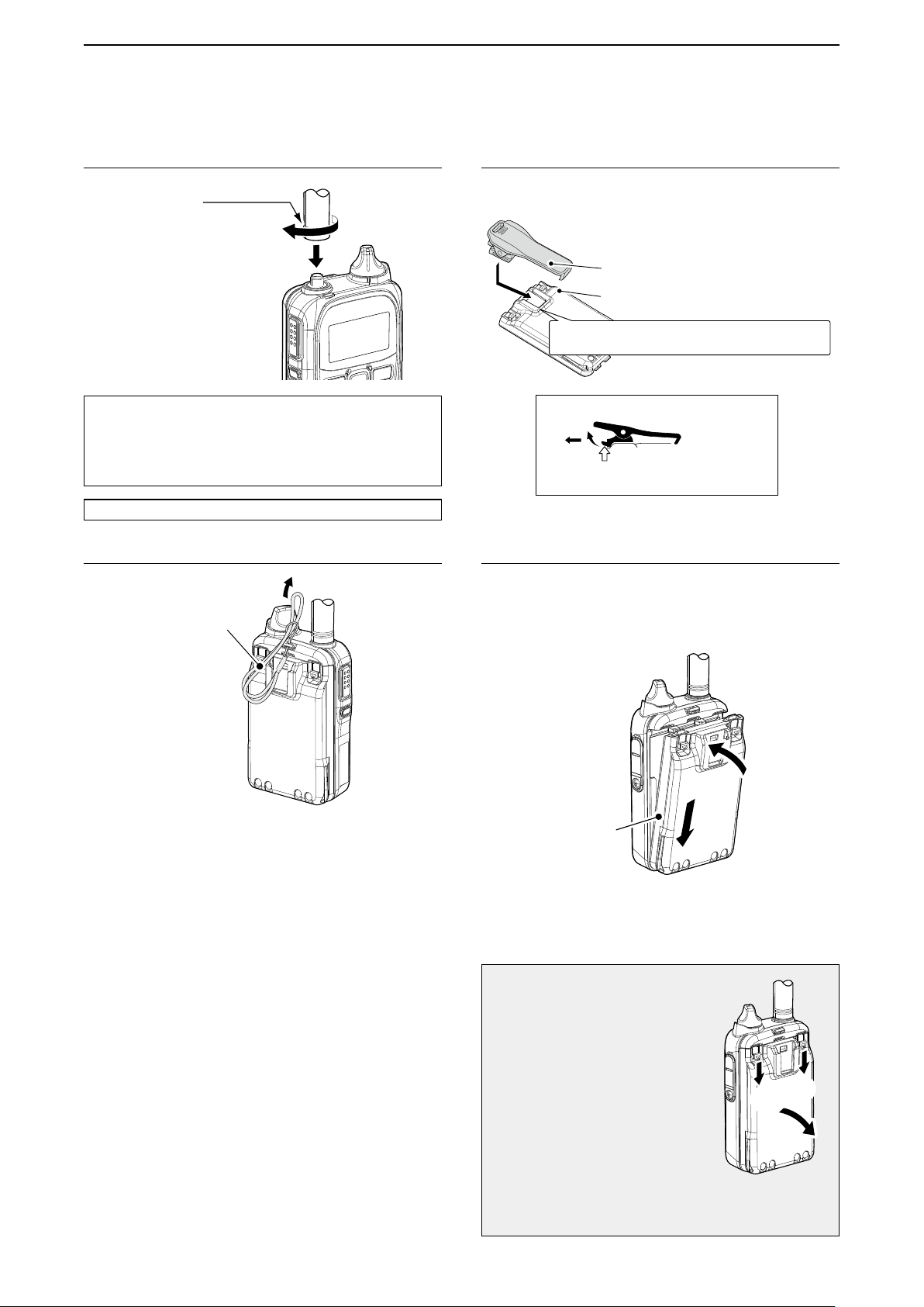
■ Attaching the antenna ■ Attaching the belt clip
Hold this part to turn.
CAUTION:
• NEVER carry the transceiver by holding only the
antenna.
• Transmitting without an antenna may damage the
internal circuit.
NOTE: You can use only the supplied antenna.
■ Attaching the hand strap
Supplied
hand strap
L Remove the battery pack before attaching or removing
the belt clip.
Belt clip
Battery pack
Slide the belt clip in the direction of the arrow until
the belt clip locks in place, and makes a ‘click’ sound.
Removing the belt clip
q
w
Lift the tab up q, and slide the belt clip in
the direction of the arrow w.
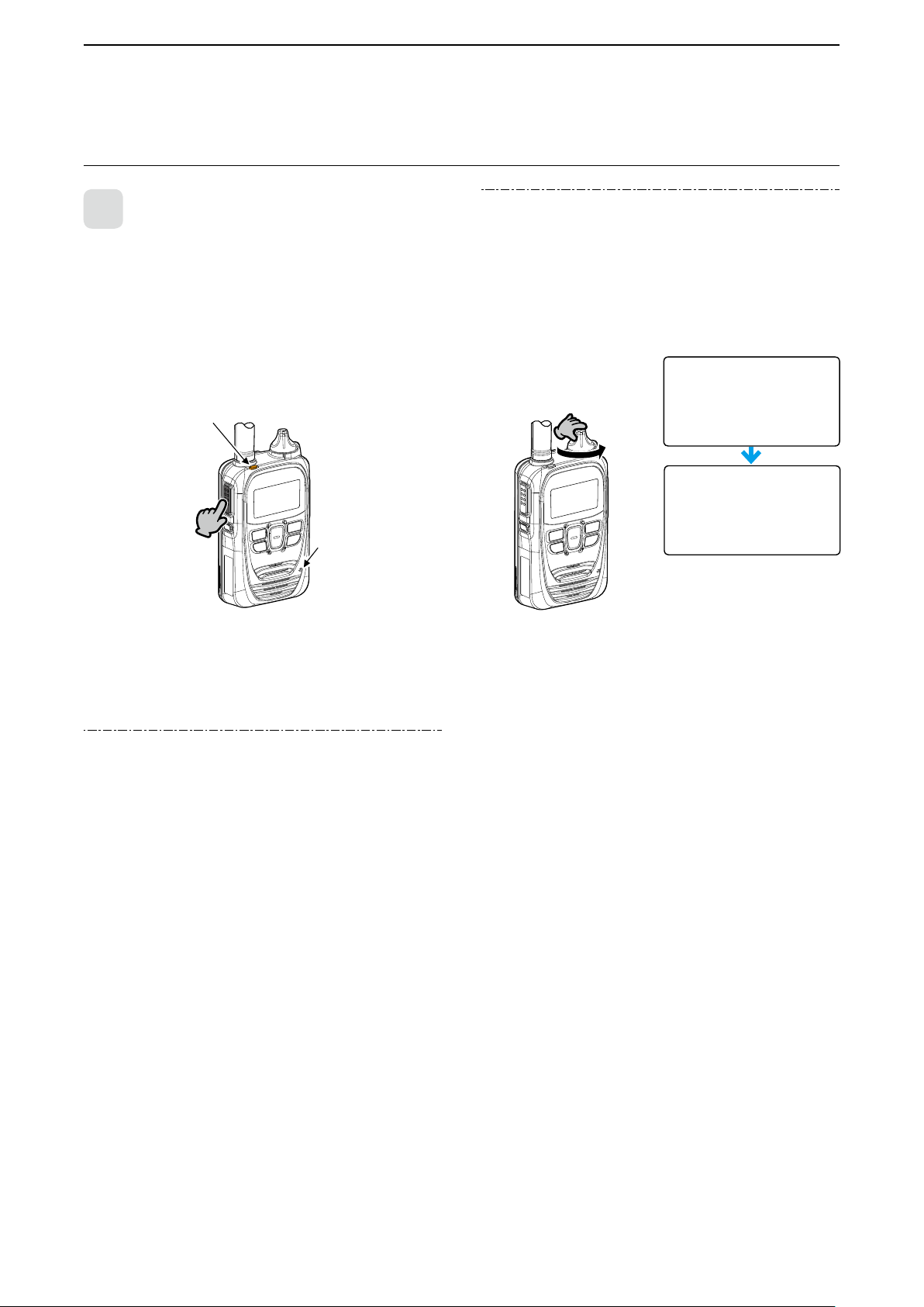
■ Attaching the battery pack
Fully charge the battery pack before turning ON for the rst
time, or after 2 month or more of no use.
L Refer to Section 5 for charging information.
q
Battery pack
Follow the order q ~ w on the illustration above.
NOTE: After attaching, check that the battery pack is
rmly attached. (2 sliding locks are in place.)
CAUTION
Even when the transceiver’s power
is OFF, a small current still ows in
the transceiver. Remove the battery
pack when not using it for a long
time. Otherwise, the battery will
become exhausted.
NOTE: Turn OFF the power before
remove the battery pack
in order q ~ w in the
illustration to the right.
L Do not remove the battery pack until “POWER
OFF…” is disappeared. Otherwise the recorded
audio may be lost.
1-2
q
q
Page 5
BEFORE USING
回す
回す
00002
Booting...
All
10/4 12:57
00002
Successful
00002
Connecting
1
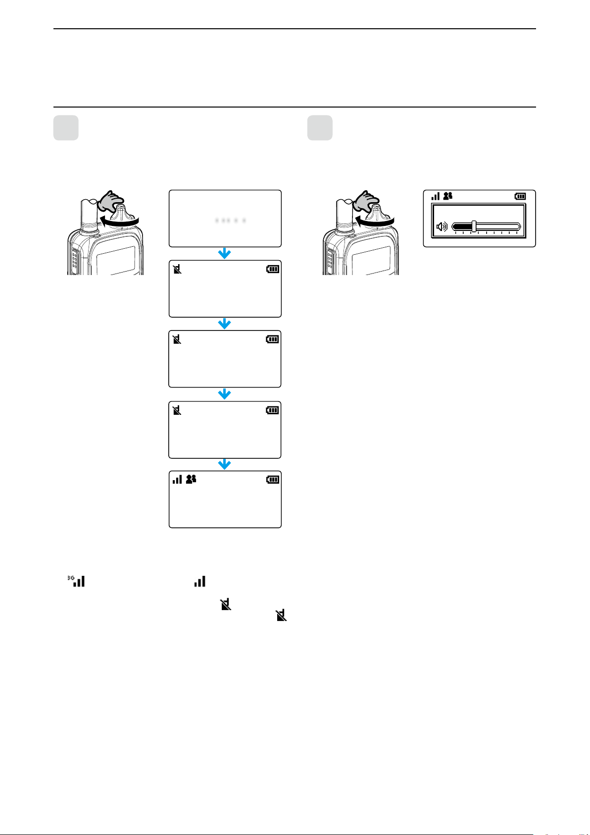
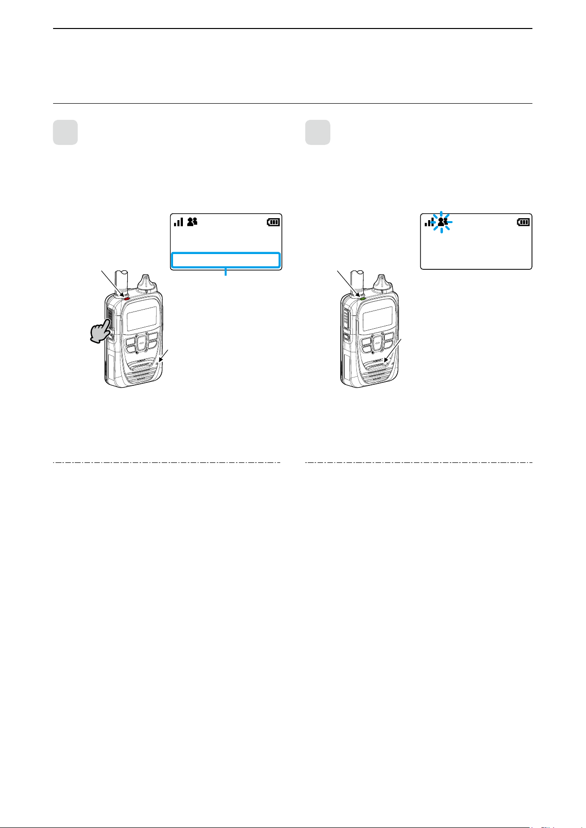
■ Turning ON the power/Adjusting the audio level
1
Turn [PWR/VOL] clockwise to the 12 o’clock position.
• A beep sounds.
L The dial is made tight
Turning ON the power
Turn
IP501H
Ver. . . /
for the dust and water
resistance.
2
Turn [PWR/VOL] to adjust the audio output level.
• The volume can be adjusted between 0 and 32.
NOTE: If the output level is set to minimum, the beep does
Adjusting the audio output level
Turn
Volume:
not sound.
10
Standby screen
The signal strength is represented by 3 bars.
In the 3G mode, the received signal strength is indicated by
the
L When the transceiver location is out of the service area,
icon. In the LTE mode, the icon is displayed.
or cannot receive the control signal, the
icon blinks. If the transceiver has not been registered,
is displayed.
(out-of-area)
1-3
Page 6
BEFORE USING
電源/音量]
アンテナ
[送信/受信]ランプ
[PTT](送信)
スイッチ
[ オ プ ション
キー
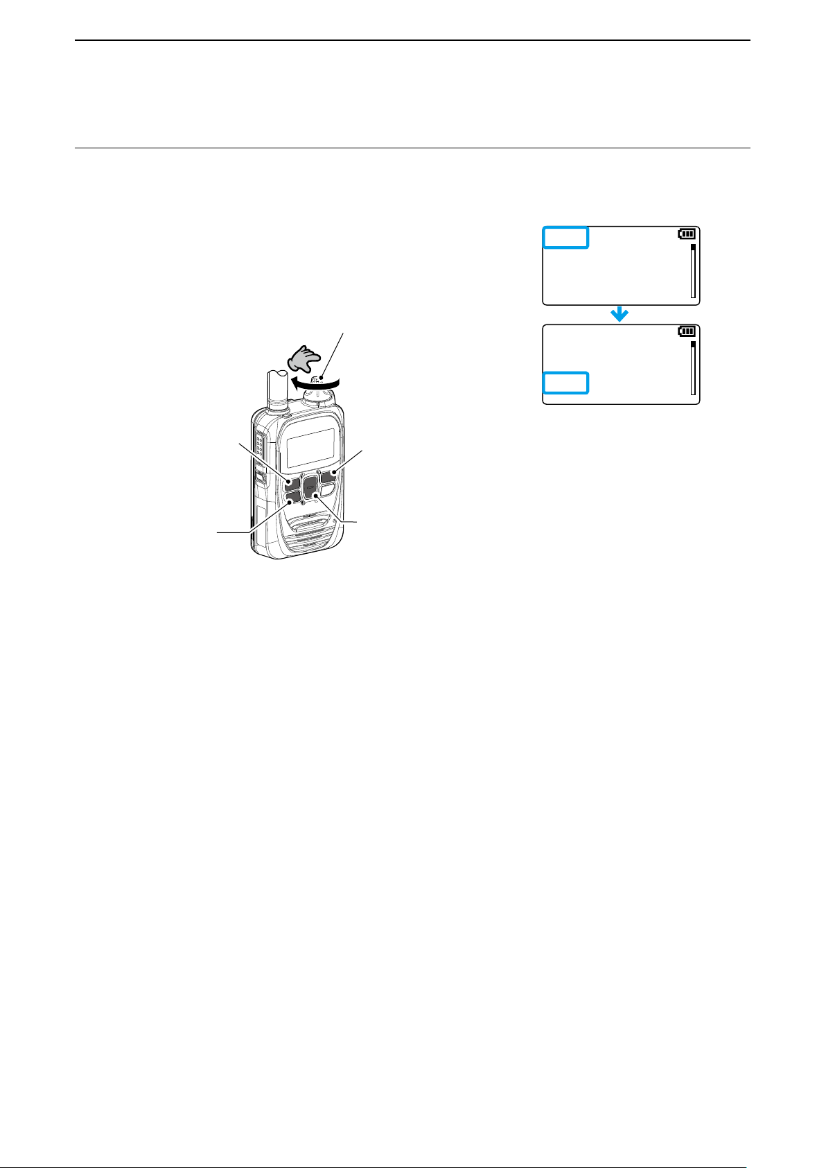
Turn OFF
1
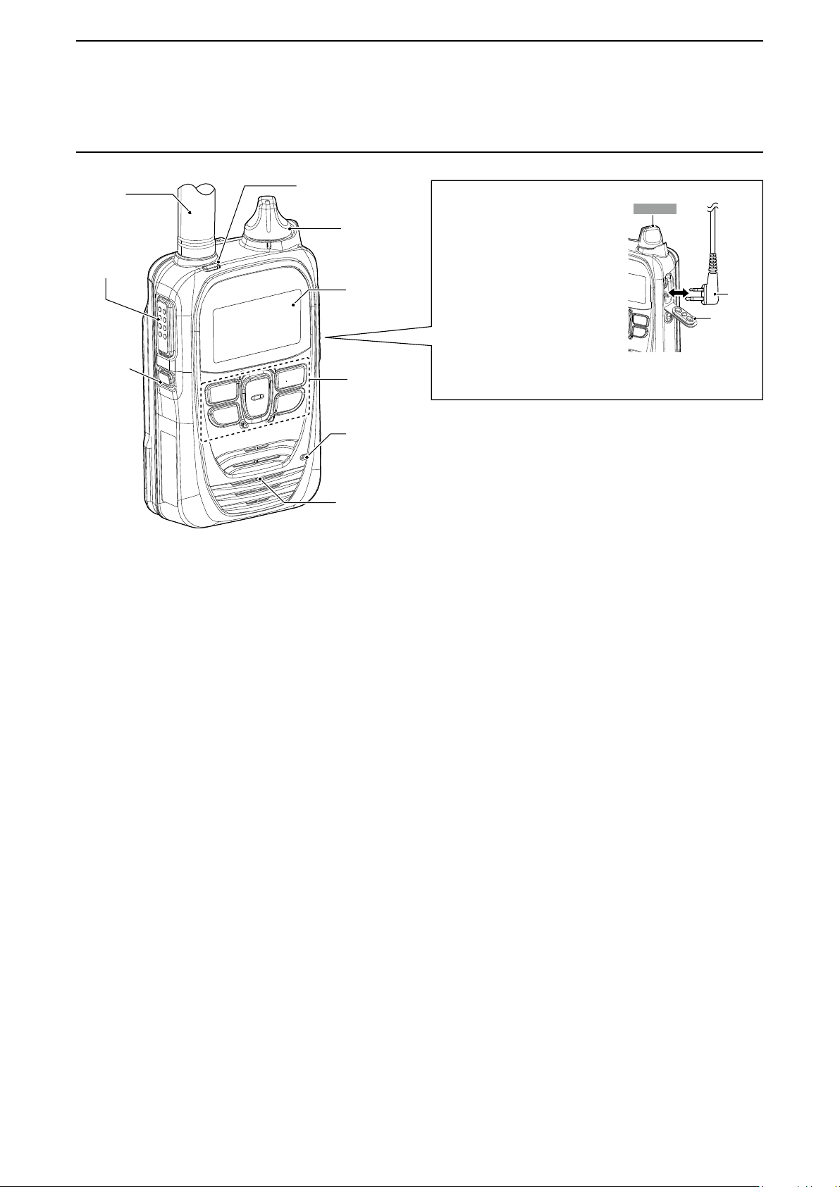
■ Panel description
Antenna
(p. 1-2)
PTT
(p. 2-2)
[Option]*
(p. 3-6)
]
1
[TX/RX] indicator
(pp. 2-2 and 2-3)
[PWR/VOL]*
[
ツマミ
(p. 1-3)
Function
表示部
screen
(p. 1-5)
操作キー
Keypad
When connecting optional equipment
• Be sure to turn OFF the power
2
before connecting or disconnecting
optional equipment to or from the
jack.
• Remove the cable by holding the
plug, not the cable.
• Insert the plug securely when
connecting the cable.
CAUTION:
Attach the jack cover when no optional equipment is
connected.
Connector
cover
(p. 1-6)
マイク
Microphone
Speaker*
スピーカー
3
NOTE: Instructions and screens on this guide may differ, depending on the settings.
*1 Ask for your dealer about the assigned function.
2
*
When the Bluetooth function is used and the “Bluetooth Synchronous Volume” item is set to “Enable” (p. 4-6), the audio
volume cannot be adjusted by [PWR/VOL] but [VOL] (+) or [VOL] (–) key on the Bluetooth device.
3
*
While connecting an optional speaker microphone or the Bluetooth function (p. 5-8) is used, the audio is not output from
the internal speaker.
Plug
1-4
Page 7

BEFORE USING
All
10/4 12:57
All
10/4 12:57
F
Updating
1
■ Icons and indications
Standby screen
Blinks
10/4 13:00
All Gather immediately
Example: A message is received
Message scrolls depend-
ing on the message length
Signal strength
The signal strength is represented by 3 bars.
When the transceiver location is out of the service
area, or cannot receive the control signal, the
(out-of-area) icon blinks.
If the transceiver has not been registered,
displayed. (p. 1-3)
Call types*
: All/Group Call
: Talkgroup Call*2 (p. 3-4)
: Individual Call
: Phone Call*
*1 Blinks when a call or message is received.
*2May be usable, depending on a presetting.
*3Feature in the near future.
1
3
is
Recording function (p. 3-7)
Bluetooth function (p. 5-8)
Pocket beep (p. 3-10)
P-Bell function (p. 3-10)
Lock function (p. 1-7)
Remaining battery capacity
Represents the remaining capacity in 4 steps.
sufficient
capacity
exhausted
a little.
nearing exhaustion
(Charging is necessary)
Blink
Exhausted
(Charging required)
“F” blinks while downloading a new firmware:
• Do not turn OFF the transceiver until the download is nished. Place the transceiver in a good signal level area.
Downloading takes approximately 10 minutes.
• After the downloading is nished, the rmware update will start. Updating takes approximately 1 minute.
• Do not turn OFF the transceiver. The transceiver will automatically restart when the update is nished.
• If "F" has been displayed for more than 10 minutes, reboot the transceiver.
• If the battery status indication is
Charge the battery pack, then restart the transceiver and do the rmware update.
(nearing exhaustion) or
Blink
(exhausted), the rmware update will not start.
1-5
Page 8

BEFORE USING
Individual
Individual 00001
00001
All
10/4 12:57
1
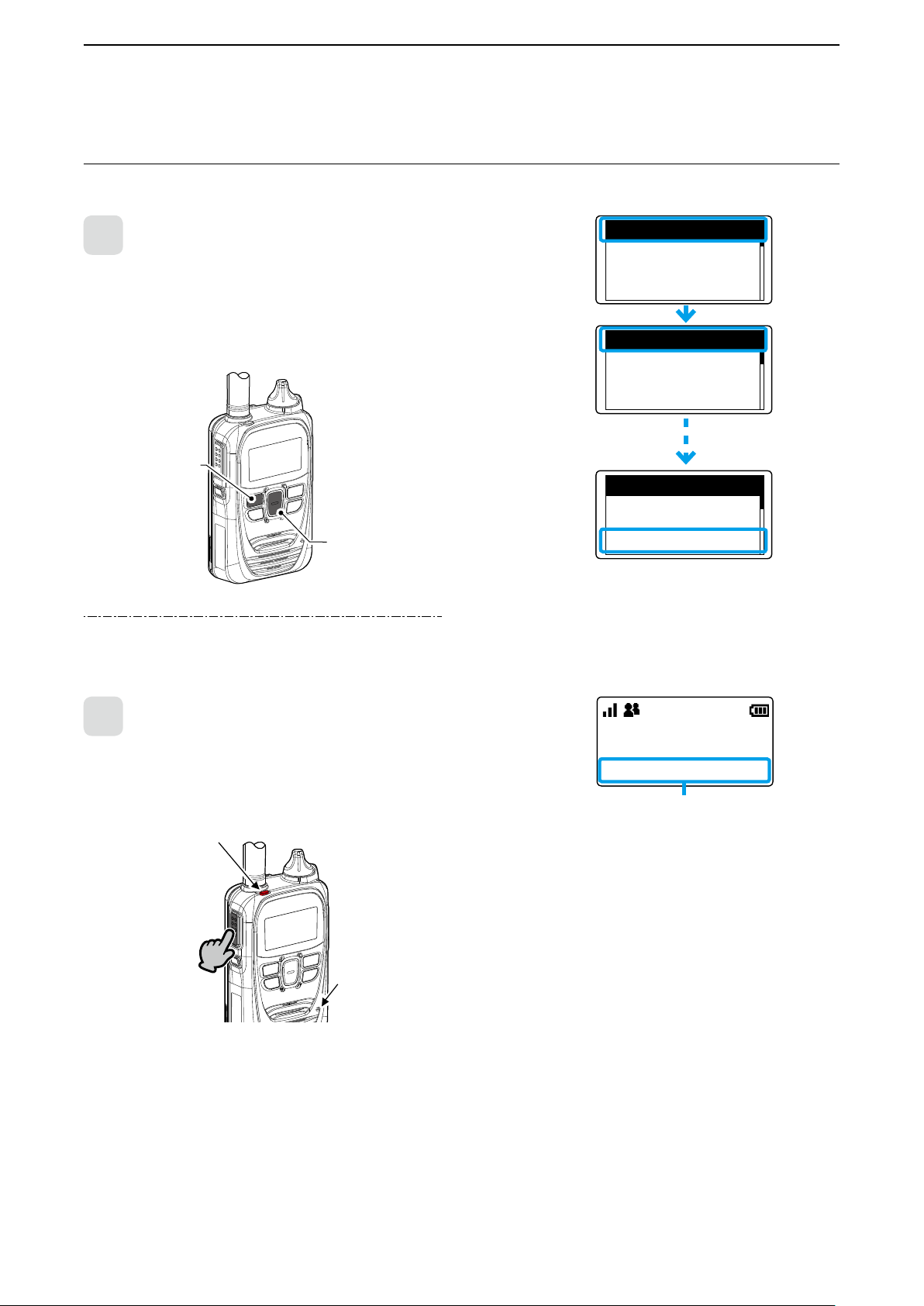
■ About the key operations
[Address] key*
Selects a calling party or group from this list.
Push [▲]/[▼] to select “All Call,” “Group Call”
or “Individual Call.”
Address book: Individual
[Call history] key*
Selects the call history.
Push
[▲]/[▼]
"TX MSG log," "RX MSG log," "TX TEL log" or
"RX TEL log."
• Hold down until “Emergency” is displayed
to send an emergency call, depending on
a presetting.
*May be usable, depending on a presetting.
to select the "TX log," "RX log,"
[FUNC] key*
Selects the message, Status
[CLR/LOCK] key
Push to return to the previous
Hold down for 1 second to turn
L [PTT] switch and [PWR/VOL] dial can
[▲]/[▼] key
Push to scroll the screen,
or move the cursor.
or Talk group to send.
Message
All
Gather immediately
(Example: A message is selected.)
screen from a function screen.
the Key Lock function ON or
OFF.
be used, even while the Key Lock
function is ON.
(Example: Key Lock function is ON.)
1-6
Page 9
BEFORE USING
All
10/4 13:00
All
10/4 12:57
[電源/音量]ツマミ
キー
[PTT]
スイッチ
1
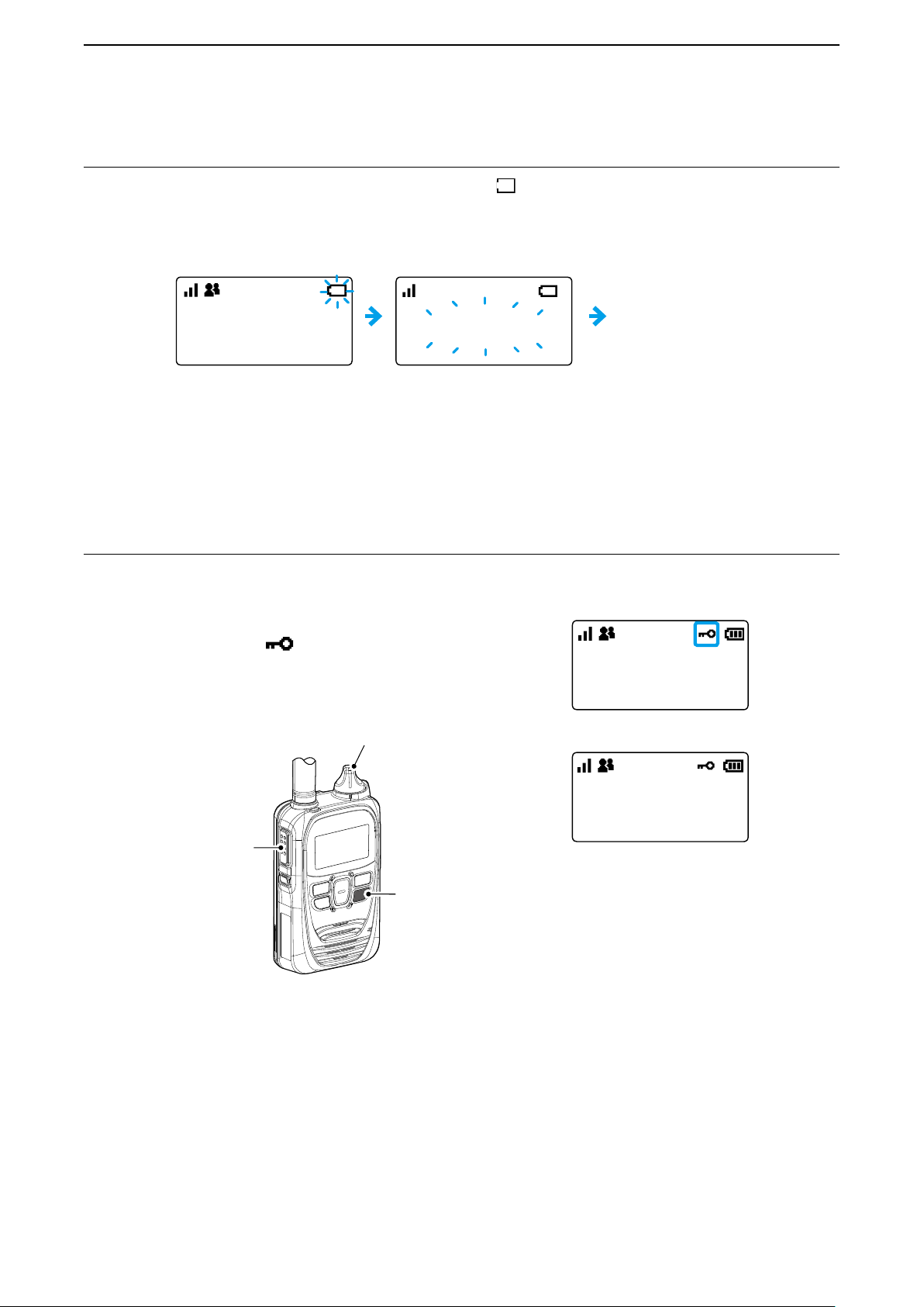
■ Battery alert beep
When the battery is almost exhausted, the battery status indicator “ ” starts blinking, and warning beeps sound every 30
seconds. Charge the battery pack immediately.
When the battery is nearly exhaustion:
Blinks
(Section 5)
Blinks
LOW BATTERY
Pi– Pi– Pi–
L
When “LOW BATTERY” is displayed and beeps sound, the transceiver power will be automatically turned OFF soon.
Pi– PiPiPi ・・・
Automatically turned OFF
■ Key Lock function
The Key Lock function prevents accidental function access.
LAn Emergency call (p. 3-12) can be made, even while the Key Lock function is ON.
z Hold down [CLR/LOCK] for 1 second.
• A beep (Pi, Pi) sounds and “ ” appears.
L Hold down [CLR/LOCK] for 1 second to cancel the function.
L [PTT] and [PWR/VOL] are functional
function is ON.
even while the Key Lock
Standby screen
[PWR/VOL]
[PTT]
(送信)
[CLR/LOCK]
[CLR/LOCK]
1-7
KEY LOCK
When a key is pushed while the Key Lock
function is ON.
Page 10

BASIC OPERATION
■ Transmitting and receiving .................................................. 2-2
■ Using the Address Book ...................................................... 2-4
■ Using the Call history .......................................................... 2-5
Section
2
2-1
Page 11
BASIC OPERATION
押し
[送信/受信]ランプ
[送信/受信]ランプ
が緑色に点灯
スピーカー
All
10/4 12:58
All
10/4 12:57
2
■ Transmitting and receiving
Hold down [PTT]
1
While holding down [PTT], speak into the microphone at
your normal voice level.
• The [TX/RX] indicator lights red while [PTT] is pushed.
が赤色に点灯
Lights red
All Call transmitting screen
つづける
Hold down
マイク
Microphone
2
When a Call is received, the received audio is heard.
• [TX/RX] indicator lights green while receiving.
Lights green
Receive a call
Blinks when a Call is received
Receiving an All Call
Speaker
Calling tip:
Hold the transceiver 2.5 inch away from your mouth, and
speak at your normal voice level. Talking too close to the
microphone, or in a loud voice can distort your voice.
About the Time-out Timer:
When the continuos transmission period exceeds 5
minutes, the Time-out Timer automatically stops the
transmission to prevent prolong transmissions.
Release the PTT, then hold down again to resume talking.
About the key touch beep:
Depending on a preset, a confirmation beep sounds when
you push a key. (p. 4-5)
About the alert:
Depending on a preset, the alert that noties the out of the
service area or receive status sounds.
About the Vibration function:
Depending on a preset, the Vibration function indicates that a
call is received. (p. 4-4)
(p. 4-5)
2-2
Page 12
BASIC OPERATION
回す
[送信/受信]ランプ
が橙色に点灯
2
■ Transmitting and receiving (continued)
Talk while receiving a call
3
While receiving a call, push [PTT] to talk in the full duplex
mode* like a telephone call.
L In the Full Duplex mode, the [TX/RX] indicator lights
orange.
L Turn [PWR/VOL] to adjust the audio output level. Do
not cover the speaker or microphone.
Blinks orange
マイクマイク
Hold down
* Depending on a preset. Ask your dealer for details.
Microphone
Turning OFF the power:
Turn [PWR/VOL] maximum counter clockwise until it
makes a “click” sound.
L Wait for 10 seconds before you turn ON the transceiver
again.
L Before you remove the battery pack from the
transceiver, be sure that the transceiver power is OFF
(The LCD is blank). (p. 1-2)
Power Off...
Turn
About the Simplex mode:
If the communication mode is set to Simplex by your
dealer, you have to take turns to communicate: Push PTT
to talk, release to receive.
LPush PTT after the other person nishes talking.
L Saying "Over" at the end of your talk makes the
About the Back Light function:
Depending on a preset, the Back Light function operation
differs. (p. 4-5)
• Always OFF: Does not light.
• Always ON: Is always lit.
• On operation: When a Call is received or a key
NOTE: When using the Audio Recording function
The recorded audio is stored into the internal memory
on power OFF. Do not remove the battery pack until
"POWER OFF…" is disappeared. Otherwise the recorded
audio may be lost.
communication smooth.
(except [PTT] and [PWR/VPL]) is
pushed, the Back Light lights, then
automatically turns OFF after 5
seconds.
2-3
Page 13
BASIC OPERATION
押し
[送信/受信]ランプ
Sales group10
10/4 12:57
キー
[ アドレ ス 帳 ]
2
■ Using the Address Book
The [Address] key can be used, depending on a preset. Ask your dealer for details.
Select a call-to party from the Address book
1
1. Push [Address] to select a Call type. (Example: Group call)
L Push this key several times to select “All,” “Group (Talkgroup),”
“Individual” or “Phone*.”
L See page 3-4 about the Talk Group.
2. Push [▲]/[▼] to select a call-to party. (Example: Sales group 10)
[Address]
キー
[▲]/[▼]
[▲]/[▼]
*Feature in the near future.
About the All or Group (Talkgroup) call:
Ask your dealer for details for call type setting.
All
All
Group
10001
Sales1
Group
10010
Sales10
2
While holding down [PTT], speak into the microphone.
• The [TX/RX] indicator lights red.
Hold down [PTT]
が赤色に点灯
Lights red
つづける
Hold down
マイク
Microphone
Address book: Group
2-4
Page 14

BASIC OPERATION
押し
[送信/受信]ランプ
10/3 12:57
Sales group1
Tx log
10/3 13:37
Sales1
Rx log
10/2 11:47
Sales8
Rx log
Sales8
10/4 14:53
キー
[履歴]
2
■ Using the Call history
The [Call history] key can be used, depending on a preset. Ask your dealer for details.
Select a call-to party from the Call history
1
1. Push [Call history] to select a call history (
L Push this key several times to select “TX log,” “RX log,” “TX MSG
log,” “RX MSG log,” “TX TEL log” or “RX TEL log.”
2. Push [▲]/[▼] to select a call-to party. (Example: Sales 8)
[▲]/[▼]
[Call history]
About the history log:
Up to 10 logs can be stored. The oldest log is automatically
deleted when the 11th call is received.
キー
[▲]/[▼]
“RX log”).
Hold down [PTT]
2
While holding down [PTT], speak into the microphone.
• The [TX/RX] indicator lights red.
が赤色に点灯
Lights red
つづける
Hold down
Microphone
マイク
Individual call transmitting screen
2-5
Page 15
BASIC OPERATION
CLR
LOG
SET
– – –
LOG
SET
2
■ Using the Call history (continued)
Deleting history logs:
1. While holding down [FUNC], turn ON the power.
2. Release [FUNC] when “SET” is displayed.
3. Push [FUNC] or [Address] several times to select “LOG.”
4. Push [▲]/[▼] to select “CLR,” then push [Call history].
• All the histories except the recorded audio are deleted.
LSee page 3-9 for deleting the recorded audio.
[Address]
[Call history]
[履歴]キー
[電源/音量]ツマミ
[PWR/VOL]
[FUNC]キー
[FUNC]
[▲]/[▼]キー
[▲]/[▼]
2-6
Page 16

ADVANCED OPERATION
■ Sending a message (Message Call) ................................... 3-2
■ Viewing received messages ................................................ 3-3
■ Status Call ........................................................................... 3-3
■ About the Group (or Talkgroup) Call .................................... 3-4
■ Selecting a Talkgroup number with the [FUNC] key ............ 3-5
■ Selecting a Talkgroup number with the [Address] key ......... 3-5
■ About the [Option] key ......................................................... 3-6
■ Recording ............................................................................ 3-7
■ Pocket Beep function ........................................................ 3-10
■ P-Bell function ................................................................... 3-10
■ About the VOX function ......................................................3-11
■ Emergency Call function ................................................... 3-12
■ Lone Worker function ........................................................ 3-13
■ Man Down function ............................................................ 3-13
■ Searching network operator .............................................. 3-14
Section 3
3-1
Page 17

ADVANCED OPERATION
All
All
Group
10001
Sales1
Individual
00001
Sales1
Individual
00002
Sales2
Sales2
Reply me
Message
Successful
10/4 12:57
キー
[ アドレ ス 帳 ]
キー
[PTT]
スイッチ
3
■ Sending a message (Message Call)
This function may be used, depending on a presetting. Ask your dealer for details.
Select a call-to party
1
1. Push [Address] to select a Call type. (Example: Individual)
L Push this key several times to select “All,” “Group (Talkgroup),”
“Individual” or “Phone*.”
LSee page 3-4 about the Talkgroup.
2. Push [▲]/[▼] to select the call-to party to send the message to.
(Example: Sales2)
キー
[Address]
[▲]/[▼]
[▲]/[▼]
*Feature in the near future.
LYou can select the call-to party also from the Call history (p. 2-5).
Select a message
2
Call-to party
1. Push [FUNC] to select “Message.”
2. Push [▲]/[▼] to select a message.
• The selected message may scroll, depending on the message length.
3. Push [PTT].
[FUNC]キー
[PTT]
(送信)
[FUNC]
Message
Sales2
Gather immediately
[▲]/[▼]
[▲]/[▼]
L When the Call type is set to “Individual,” the call
result (Success/Failed) is displayed after sending.
3-2
Page 18

ADVANCED OPERATION
At meeting
Status
10/4 12:57
All Gather immed
Rx MSG log
10/8 13:10
Sales1 Reply me
Rx MSG log
キー
[PTT]
スイッチ
キー
[履歴]
3
■ Viewing received messages
This function may be used only when the Talkgroup Call function is assigned to the [Call history] key. Ask your dealer for
details.
1. Push [Call history] to select “Rx MSG log.”
2. Push [▲]/[▼] to browse the message on the screen.
• The selected message may scroll, depending on the message length.
Received date and time
[Call history]
キー
[▲]/[▼]
[▲]/[▼]
The Sender and Received message
are displayed
■ Status Call
This function may be used only when the Status function is assigned to [FUNC], and the status (Example: “Meeting,”
“Break,” and so on) is set. Ask your dealer for details.
1. Push [FUNC] to select “Status.”
2. Push [▲]/[▼] several times to select a status.
3. Push [PTT] to transmit.
[FUNC]キー
[PTT]
(送信)
[FUNC]
Status
Selected status
At lunch
[▲]/[▼]
[▲]/[▼]
3-3
Page 19
ADVANCED OPERATION
3
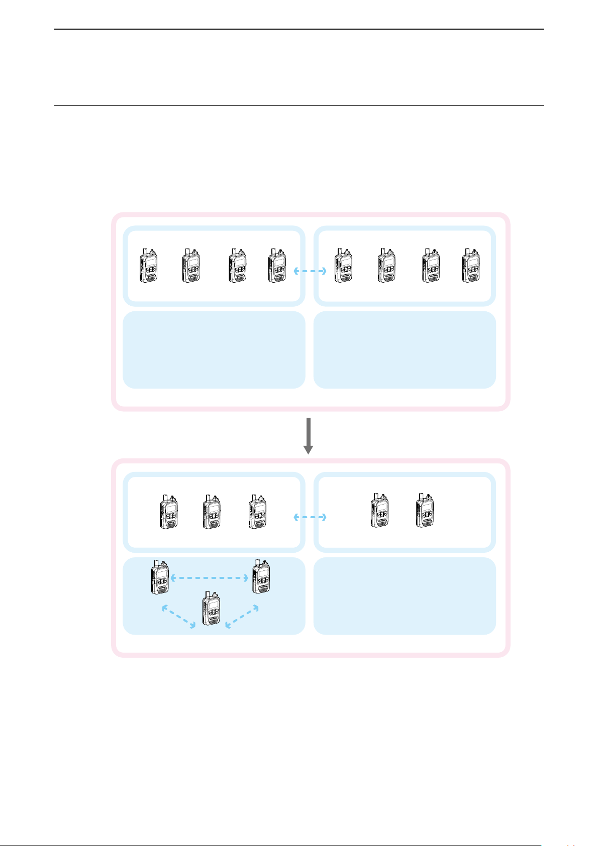
■ About the Group (or Talkgroup) Call
The Talkgroup Call function enables the user to communicate with call-to parties in the same Talkgroup.
For example, in the illustration below, when IP501H “00004” in its normal group “10001” selects Talkgroup “20001,” it is
excluded from group “10001,” and can communicate with only IP501Hs “0006” and “0008” that belong to group “20001.”
L This function may be used only when the Talkgroup number is registered and the Talkgroup Call function is assigned to
a key by your dealer.
L Ask your dealer about whether or not to include the Talkgroup in the All Call.
When Talkgroup is OFF
00001 00002 00003
Talkgroup 20001
全体
All
When Talkgroup is selected
Group 10001
Group 10001
00004
Group 10002
00005 00007 0000800006
Talkgroup 20002
Group 10002
00001
00004 00008
All
00002 00003
Talkgroup 20001
00006
00005 00007
Talkgroup 20002
3-4
Page 20

ADVANCED OPERATION
OFF
Talkgroup
Talkgroup
Talkgroup1
20001
Talkgroup
Talkgroup1
20001
Talkgroup1
10/4 12:57
Talkgroup1
10/4 12:57
Group
10001
Sales1
3
■ Selecting a Talkgroup number with the [FUNC] key
This function may be used only when the Talkgroup Call function is assigned to the [FUNC] key. Ask your dealer for details.
1. Push [FUNC] to select “Talkgroup.”
2. Push [▲]/[▼] to select a Talkgroup number you want to
belong to. (Example: 20001)
3. Push [CLR/LOCK].
• The transceiver is ready to talk to only the transceivers that belong
to the same Talkgroup.
L While the Talkgroup number is selected, the Normal Group call
cannot be made. (p. 3-4)
L You can leave the Talkgroup and return to the Normal Group by
selecting “OFF” in Step 2 on the “Talkgroup” screen.
[Address]
[FUNC]
[CLR/LOCK]
[▲]/[▼]
“Talkgroup1” is selected
■ Selecting a Talkgroup number with the [Address] key
This function may be used only when the Talkgroup Call function is assigned to [Address] key. Ask your dealer for details.
1. Push [Address] to select “Group.”
• Each push changes the Call type.
2. Push [▲]/[▼] to select a Talkgroup number you want to
belong to. (Example: 20001)
3. Push [CLR/LOCK].
• The transceiver is ready to talk to only the transceivers that belong
to the same Talkgroup.
L While the Talkgroup is selected, the Normal Group call cannot be
made. (p. 3-4)
L You can leave the Talkgroup and return to the Normal Group by
selecting “OFF” in step 2 on the “Talkgroup” screen.
[Address]
[ アドレ ス 帳 ] キー
[CLR/LOCK]キー
[CLR/LOCK]
[▲]/[▼]キー
[▲]/[▼]
“Talkgroup1” is selected
3-5
Page 21

ADVANCED OPERATION
Recording Log
Sales8
10/4 14:53
All
MUTE
[ オ プ ション ]
3
■ About the [Option] key
One of the following functions may be assigned to the [Option] key by your dealer. Ask your dealer for details.
ASSIGNABLE FUNCTIONS:
Message Selects an often used message.
One touch Selects the often used Call type or Call-to party.
Hangs up a Telephone call*.
LYou can cancel the call by pushing [Option] again.
Clear Down
Mute
L The transceiver can terminate the Telephone call when:
• The call type is “Individual” and the call was initiated by the telephone.
• The call is initiated by the transceiver.
Mutes or unmutes the received audio. (The notication tone is not muted.)
• Hold down [Option] for 1 second.
LPushing [PTT] also releases the mute.
Playbacks
Emergency
*Feature in the near future.
[Option]
Plays back the recorded audio.
Transmits an Emergency call.
• Hold down [Option] until “Emergency” is displayed.
L The Emergency call is cancelled when:
• A call is received.
• You hold down [Option] until “Emergency” disappears.
• The transceiver power is turned OFF.
• The time set in the “Cancel by Time” item has elapsed.
キー
Message
Sales2
Gather immediately
Often used message
Often called Call-to party
10/4 12:57
Sales2
Recorded audio
(In the Call history log)
3-6
Mute function is ON.
Page 22
ADVANCED OPERATION
– – –
LOG
SET
Enable
Recording
SET
3
■ Recording
The Recording function records the audio of received calls.
The recording duration of a single le is up to 1 minute. The oldest le will be automatically overwritten when the 5th call is
recorded.
L You can play the recorded audio only when the Playback function is assigned to [Option] by your dealer.
LAs the default setting, you can record only Individual calls. You can change this setting in the Set mode (p. 4-7).
LOnly the call-to party’s voice is recorded.
LThe recorded audio data cannot be exported.
NOTE: When removing the battery pack
The recorded audio is stored in memory on Power OFF. Do not remove the battery pack until “POWER OFF…” is
disappeared. Otherwise the recorded audio may be lost.
1. Setting the Recording function enable
1. While holding down [FUNC], turn ON the power.
• Enter the Set mode.
2. Release [FUNC] when "SET” is displayed.
3. Push [FUNC] or [Address] several times to select “Recording.”
4. Push [▲]/[▼] to select “Enable.”
5. Push [CLR/LOCK].
• Exits the Set mode.
[Address]
[FUNC]
[CLR/LOCK]
[▲]/[▼]
3-7
Page 23
ADVANCED OPERATION
10/3 12:57
Sales group1
Tx log
10/3 13:37
Sales1
Recording log
Playback
Sales1
Recording log
キー
[ オ プ ション ]
Recording
Recording
All
10/4 12:57
3
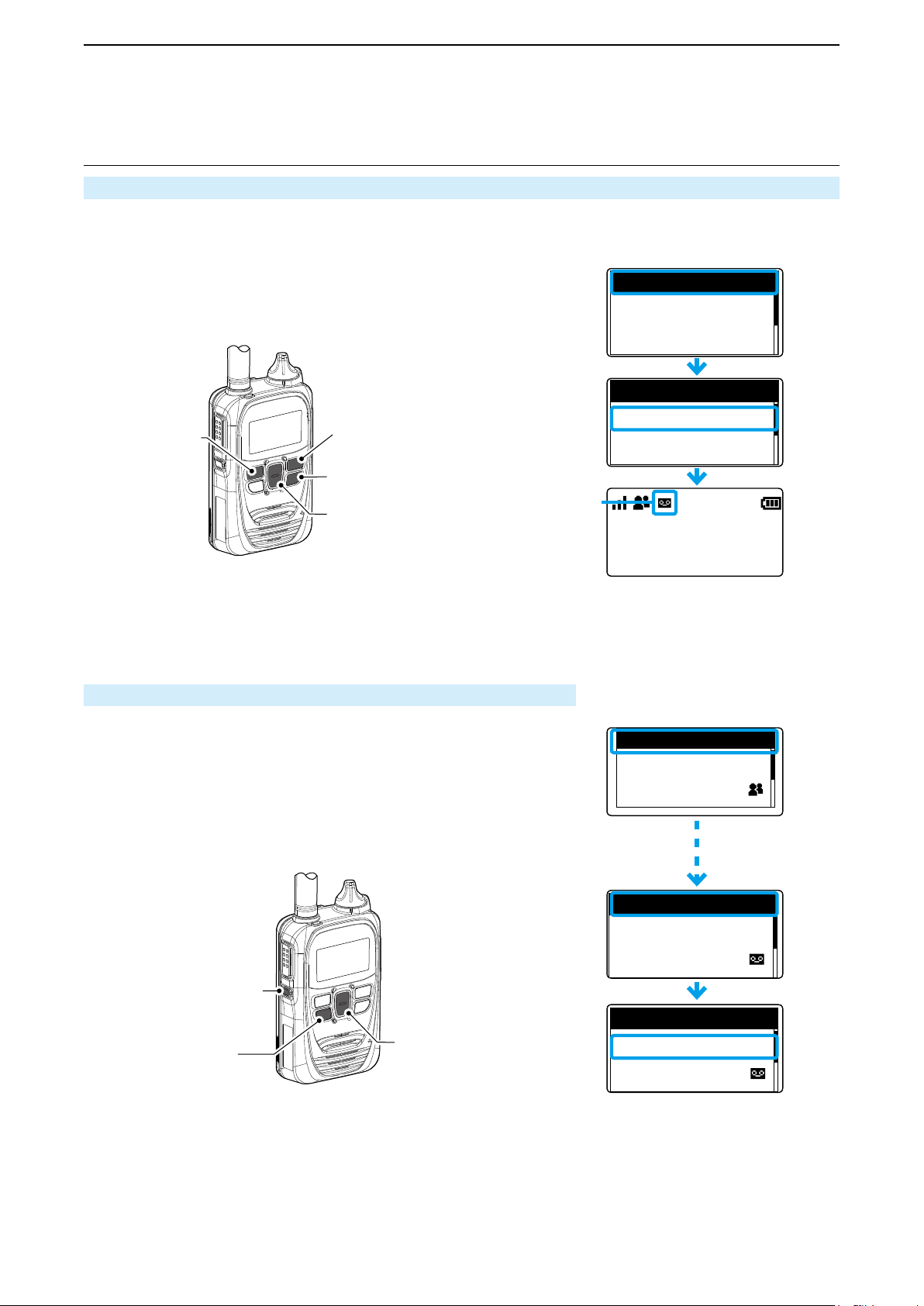
■ Recording (continued)
2. Turning ON the Recording mode
1. Push [FUNC] to select “Recording.”
2. Push [▲]/[▼] to select “ON."
3. Push [CLR/LOCK].
• The Recording mode is ON, and the Recording mode icon is displayed.
• The icon blinks when there is a recorded audio that has not been played yet.
OFF
[Address]
3. Playing the recorded audio
[FUNC]
[CLR/LOCK]
Recording mode icon
[▲]/[▼]
1. Push [Call history] several times to select “Recording log.”
2. Push [▲]/[▼] several times to select the recorded audio to play.
3. Push [Option].
• The selected record audio is played.
• Push [Option] to stop playing.
ON
The Recording mode is ON
[Option]
[Call history]
[履歴]キー
キー
[▲]/[▼]
[▲]/[▼]
3-8
Page 24

ADVANCED OPERATION
– – –
LOG
SET
CLR
Delete Recorded A
SET
Deleting···
Delete Recorded A
SET
– – –
Delete Recorded A
SET
[電源/音量]ツマミ
キー
[履歴]
3
■ Recording (continued)
4. Deleting all the recorded audio history
1. While holding down [FUNC], turn ON the power.
• Enter the Set mode.
2. Release [FUNC] when “SET” is displayed.
3. Push [FUNC] several times to select “Delete Record Audio.”
4. Push [▲]/[▼] to select “CLR.”
5. Push [Call history].
• Exits the Set mode.
[PWR/VOL]
[FUNC]キー
[FUNC]
[Call history]
キー
[▲]/[▼]
[▲]/[▼]
3-9
Page 25

ADVANCED OPERATION
All
10/4 12:58
All
10/4 12:58
Sales1
10/4 12:58
3
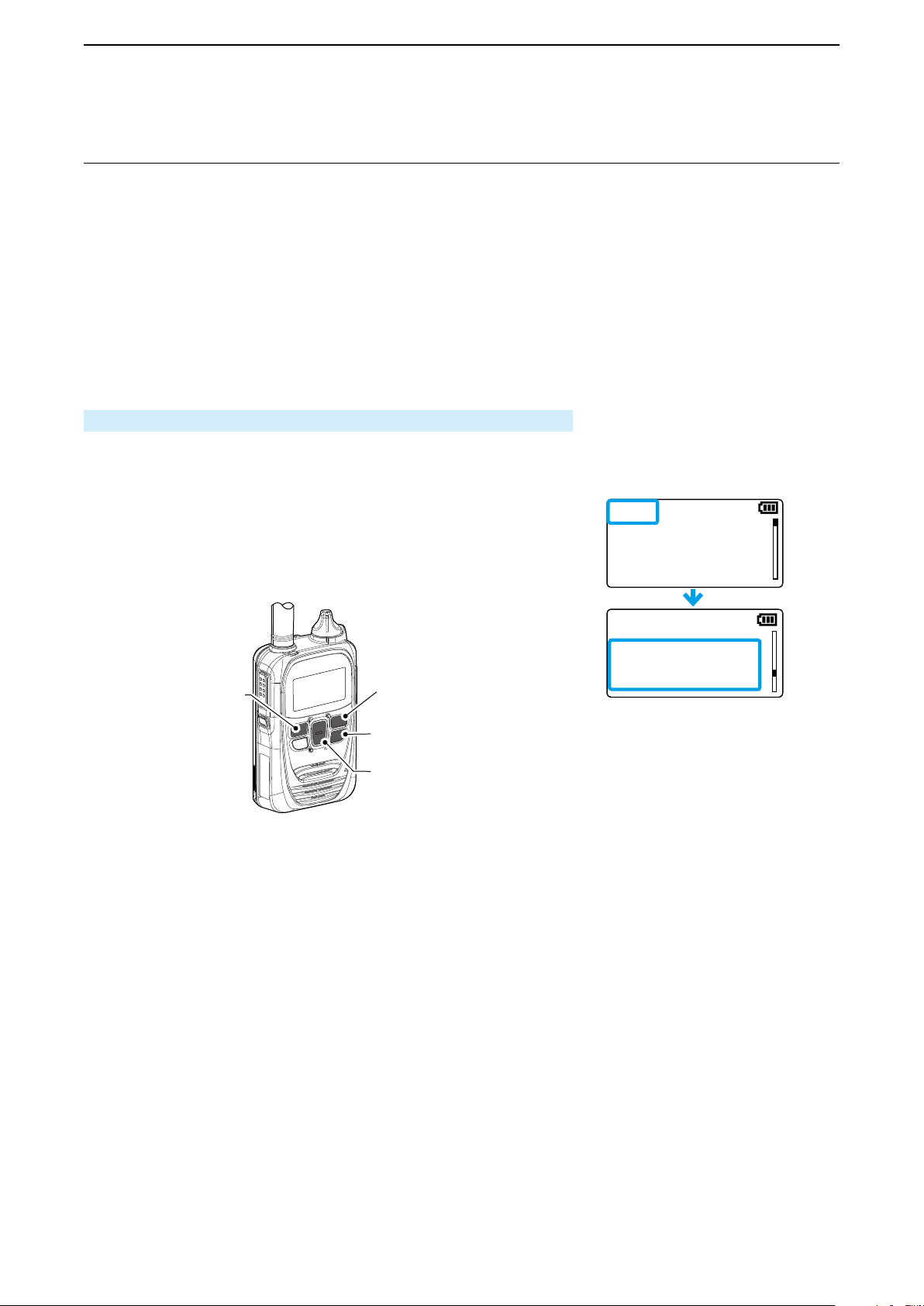
■ Pocket Beep function
The Pocket beep function sounds a notication tone and
indication when a call is received.
L This function is set by your dealer, or in the Set mode.
(p. 4-4)
L When the Pocket Beep function is ON, “
displayed.
• When a call is received, the notication beep sounds
and “
” blinks.
Standby screen
Blinks
” is
■ P-Bell function
The P-Bell function sounds the notication tone when a
call is received.
The
icon is displayed when the P-Bell function is used.
L This function is set by your dealer, or in the Set mode.
(p. 4-4)
L You cannot listen to the call until you reply to the call.
After pushing [PTT], the mute is released.
Standby screen
When an Individual call is received
3-10
Page 26

ADVANCED OPERATION
(別売品)
Turn OFF
3
■ About the VOX function
The VOX function automatically switches between receive and transmit during voice operation.
When the VOX function is ON, speak into the headset microphone to transmit, then stop speaking to listen. In full-duplex,
you can speak and listen to the call-to party at the same time.
To use this function, an optional headset and a VOX converter cable, shown below are required.
L This function is set by your dealer.
L You can congure the setting in the Set mode. (p. 4-5)
OPC-2006LS
(Option)
OPC-2006LS
(別売品)
HS-94
(Option)
[マイク/スピーカー]
ジャッ ク に 接 続 す る
To the [MIC/SP] jack
HS-94
NOTE:
Be sure to turn OFF the power before connecting or disconnecting optional equipment to or from the jack.
• Remove the cable by holding the plug not cable.
• Insert the plug securely when connecting the cable.
• Attach the jack cover when no optional equipment is connected.
L The jack is made tight to resist dust and water intrusion.
Plug
Connector
cover
Jack cover is attachedAttaching an optional equipment
3-11
Page 27

ADVANCED OPERATION
Sales2
Emergency
Sales1
Emergency
All
10/4 12:57
3
■ Emergency Call function
The Emergency Call function may be assigned to the [Option] or [Call history] key by your dealer. Ask your dealer about the
assigned function.
Transmitting an Emergency call:
1. Hold down [Option] or [Call history] until
“Emergency” is displayed.
• An alarm sounds periodically.
L When the Silent mode is set to “ON” by your
dealer, no alarm sounds, and no emergency
indication is displayed.
2. Wait for the answer back.
• When the transceiver receives an answer back, the
alarm stops, and the [TX/RX] indicator lights green.
L To cancel the emergency call, hold down [Option]
until “Emergency” disappears, or turn OFF the
transceiver.
Emergency screen Emergency screen
in the Silent mode
When an Emergency call is received:
1. “Emergency” is displayed and the alarm
periodically sounds.
L When the Silent mode is set to “ON” by your
dealer, no alarm sounds.
2. While holding down [PTT], talk into the
microphone.
• While holding down [PTT], the [TX/RX] indicator
lights red.
• The alarm stops.
• Returns to the normal mode when PTT is released.
Blinks
When an Emergency call is received
[送信/受信]ランプ
[送信/受信]ランプ
[TX/RX] indicator
[Option]
[ オ プ ション ] キー
が赤色に点灯
Lights red
[PTT](送信)
[PTT]
スイッチ
NOTE:
Icom is not responsible for the destruction or damage caused by using the Emergency Call function.
This function may not properly work under the following circumstances or conditions:
• Remaining battery capacity is low.
• Surrounding area or environment.
• The Emergency function is not designed for secured communications.
マイク
Microphone
3-12
Page 28

ADVANCED OPERATION
3
■ Lone Worker function
When the Lone Worker function is activated, the Emergency function (p. 3-12) is automatically turned ON after the transceiver has been left without any operation for the specied time period.
To reset the timer, operate any key or the volume control within the specied time period.
L This function may be used only when the Lone Worker function is programmed by your dealer.
■ Man Down function
When the Man Down function is activated, the Emergency function (p. 3-12) is automatically turned ON after the set period
of time has passed with the transceiver leaning past the preset angle.
To reset the timer, raise back the transceiver from the preset angle towards the vertical position within this set time period.
L This function may be used only when the Man Down function is programmed by your dealer.
NOTE:
Icom is not responsible for the destruction or damage caused by using the Lone Worker or Man Down function.
These functions may not properly work, depending on the following circumstances or conditions:
• Remaining battery capacity is low.
• Surrounding area or environment.
• The Lone Worker and Man Down function are not designed for secured communications.
3-13
Page 29

ADVANCED OPERATION
– – –
LOG
SET
– – –
LOG
SET
User select
Network Selection
SET
Search
Network Search
ABCD
12345
Network Search
Configured
Network Search
3
■ Searching network operator
The Network Search function search the available operator.
1. Setting the Network Search function enable
1. While holding down [FUNC], turn ON the power.
• Enter the Set mode.
2. Release [FUNC] when “SET” is displayed.
3. Push [FUNC] or [Address] several times to select “Network
Selection.”
4. Push [▲]/[▼] to select “User Select.”
5. Push [CLR/LOCK].
• Exits the Set mode.
[Address]
2. Starting a Network Search
1. Push [FUNC] several times to select “Network Search.”
2. Push [Call history] to start a search.
• Network search starts.
• The search result will be displayed in few minutes.
L Search may take a time, depending on the environment.
LIf “Timeout” is displayed, try a different location.
3. Push [▲]/[▼] to select an operator.
• Select “Search” if you start the search again.
4. Push [Call history] to set the selected operator.
• “Congured” is displayed.
[FUNC]
[CLR/LOCK]
[▲]/[▼]
[Call history]
NOTE:
• This function may not work, depending on the country of use or service provider setting.
• The transceiver may not connect to the operator in the search result, depending on the communication service contract.
(For example: Roaming is not supported.)
[FUNC]
(Example)
[▲]/[▼]
3-14
Page 30

SET MODE
■ Entering to the Basic Set mode ........................................... 4-2
■ Entering to the Advanced Set mode .................................... 4-2
■ Operation in the Set mode .................................................. 4-3
■ Set mode item list ................................................................ 4-4
Section
4
4-1
Page 31

SET MODE
– – –
LOG
SET
– – –
LOG
SET
[電源/音量]ツマミ
キー
[電源/音量]ツマミ
[ アドレ ス 帳 ]
4
There are 2 types of Set mode: Basic and Advanced.
■ Entering to the Basic Set mode
You cannot transmit nor receive while the transceiver is in the Set mode.
1. While holding down [FUNC], turn ON the power.
2. Release [FUNC] when “SET” is displayed.
[PWR/VOL]
[FUNC]
[FUNC]
■ Entering to the Advanced Set mode
You cannot transmit or receive while the transceiver is in the Set mode.
1. While holding down [FUNC] and [Address], turn ON the
power.
2. Release both keys when “SET” is displayed.
[PWR/VOL]
[FUNC]キー
[Address]
キー
[FUNC]
4-2
Page 32

SET MODE
– – –
LOG
SET
YES
FIRM UP
SET
10
Key-Touch Beep Vo
SET
Connecting···
FIRM UP···
SET
Updating···
FIRM UP···
SET
0
Key-Touch Beep Vo
SET
Rcvd
FIRM UP
SET
[履歴]
キー
[ アドレ ス 帳 ]
Updating
4
■ Operation in the Set mode
1. Push [FUNC] or [Address] to select an item.
2. Push [▲]/[▼] to set the value.
3.
Push [PTT] or [CLR/LOCK] to save the value and exit the Set mode.
• Push [Call history] to execute the following functions.
• LOG
• RESET*
• FIRM UP*
• Delete Recorded Audio
• Delete Bluetooth Device
• Search Bluetooth Device
• Initialize Bluetooth Unit
* After performing these functions, the transceiver automatically restarts.
L Updating the rmware takes approximately 10 minutes.
Example: Setting the Key-Touch Beep Volume
[Address]
[Call history]
キー
キー
[FUNC]
[FUNC]キー
[CLR/LOCK]
[CLR/LOCK]
[▲]/[▼]キー
[▲]/[▼]
Setting the Key Touch Beep Volume to “0”
Example: Updating the rmware
Updating the firmware
4-3
Page 33

SET MODE
4
■ Set mode item list
The shaded items (■ ■ ) are also displayed in the Basic Set mode.
LItems or default values may differ, depending on the presetting. Ask your dealer for details.
Item Description Option/range Default
LOG Deletes logs. ––– , CLR (Clear) –––
Initializes the transceiver.
Reset
FIRM UP Updates the rmware. NO or YES NO
Success Tone
Failure Tone
IND Call Tone
GRP Call Tone
ALL Call Tone
TEL Call Tone*
IND Crtsy Beep
GRP Crtsy Beep
ALL Crtsy Beep
TEL Crtsy Beep*
IND RX Tone
Grp RX Tone
All RX Tone
Tel RX Tone*
MSG RX Tone
IND Notify Type
GRP Notify Type
ALL Notify Type
TEL Notify Type*
IND Notify No.
GRP Notify No.
ALL Notify No.
TEL Notify No.*
MSG Notify No.
RX Notify Actn. Sets the call or message receive notication type.
RX Notify Vol.
Out of Rng Tone
Range Side Tone
*Feature in the near future.
Returns to the default values except the Bluetooth
pairing list.
Sets the successful tone for Individual calls.
L The success or failure result is also displayed
on the screen.
Sets the failure tone for Individual calls
L The success or failure result is also displayed
on the screen.
Sets the call initiation tone.
Sets the call termination tone.
Sets the call receive tone.
Sets the call receive notication type. Pocket beep or P-Bell P-Bell
Sets the number of tone.
Sets the call or message receive notication volume.
Sounds the out-of-area warning beep. The beep
also sounds when the transceiver reenters the
service area.
(
Out-of-area: “Pipi,” Reenters: “Popo”)
Mutes the sidetone when the transceiver is outof-area.
NO or YES NO
Disable or Enable Enable
Disable or Enable Enable
Disable, Tone1 ~ Tone8
L Larger number makes the
tone lower.
Disable, Tone1 ~ Tone8
L Larger number makes the
tone lower.
Disable, Tone1 ~ Tone8
L Larger number makes the
tone lower.
Continuous, 1, 3, 10, 20 (times)
Tone, Vibration, Notication
Beep + Vibration
0 ~ 32 10
Disable or Enable Disable
Disable or Enable Disable
Tone1 (Pi)
Tone1 (Pi)
Disable
3 (times)
Tone
4-4
Page 34

SET MODE
4
■ Setting item list (continued)
The shaded items (■ ■ ) are also displayed in the Basic Set mode.
LItems or default values may differ, depending on the presetting. Ask your dealer for details.
Item Description Option/range Default
The Sidetone function outputs the transmitting audio to a headset that is connected to the
Sidetone
Sidetone Volume Sets the Side tone volume. 0 ~ 32 10
VOX
VOX Threshold
Echo Canceller
Noise Canceller
BackLight Sets the backlight operating function. Auto, OFF or ON Auto
Contrast Sets the screen contrast. 1 (lowest) ~ 16 (highest) 8
Mic Gain
Notify Beep Vol. Sets the notication beep level. 0 ~ 32 10
Key-Touch Beep Sets the Key-touch beep. Disable or Enable Enable
Key Beep Vol. Sets the Key-touch beep level. 0 ~ 32 10
RX Buffer Type
Tx Inhibit
PTT Lock Inhibits transmission by the internal PTT. Disable or Enable Disable
Call Type Stnby
One Touch PTT
transceiver.
When this item is set to “Enable,” the Echo Canceller function is automatically set to “Disable.”
Automatically switches between receive and
transmit by detecting your voice.
Sets the VOX gain level.
L
Lower values make the VOX function more
sensitive to your voice.
Sets the Echo Cancelling function.
( commonly used for an earphone MIC and
headset)
When the “SideTone” item is set to “Enable,” this
item is xed to
Sets the Noise Cancelling function.
( commonly used for a transceiver, earphone MIC
and headset)
Sets the microphone sensitivity.
L Higher values make the microphone more
sensitive to your voice.
Sets the Jitter buffer size.
L Jitter buffer reduces audio interruptions.
Inhibits transmission.
Select “Enable” to lock all the controls except
[PWR/VOL].
L Transmission is also inhibited while using an
external microphone, and the VOX function.
Displays the call-to party (Call type) on the
standby screen.
Toggles receiving and transmitting by momentarily pushing [PTT].
Push [PTT] to talk, then push again to return to
receive.
L When “Enable” is selected, “One Touch PTT”
is displayed when [FUNC] is pushed.
“
Disable.
”
Disable or Enable Disable
Disable, Bluetooth Mic,
Headset or
0% ~ 100% 40%
Disable or Enable Enable
Disable or Enable Enable
-12 dB (lowest) ~ 12 dB
(highest) (in 3 dB step)
Dynamic,
40 ~ 480 milliseconds
(in 40 milliseconds step)
Disable or Enable Disable
Disable or Enable Enable
Disable or Enable Disable
Earphone-Mic
Disable
0 dB
Dynamic
4-5
Page 35

SET MODE
All
10/4 12:57
4
■ Setting item list (continued)
The shaded items (■ ■ ) are also displayed in the Basic Set mode.
LItems or default values may differ according to a presetting. Ask your dealer for details.
Item Description Option/range Default
Displays the call-to party (call type) on the standby screen.
Disable, Transmit,
Destination ID
Call-to paty (call type)
L If "Disable" is selected, the call-to party (call
type) that is preset by your dealer is displayed
on the standby screen.
Bluetooth Sets the Bluetooth function. Disable or Enable Disable
BT Auto Connect Automatically connects a Bluetooth device. Enable or Disable Enable
Sets the audio volume setting type for a Bluetooth
BT Sync Vol.
BT Connect Type
PTT & Mic Switch
BT Echo Canceller
BT E-Cancel Gain
BT E-Cancel Delay
BT Noise Cancel
BT Power Save
headset.
L When "Enable" is selected, the Bluetooth
headset volume can be set by [PWR/VOL].
Sets the Synchronous Connection-Oriented
(SCO) link* connection type of a Bluetooth
headset.
When “Auto Disconnect” is selected, the SCO
link is automatically disconnected after two
seconds.
* A Bluetooth link for voice communication
L This setting is valid only when a Bluetooth
device other than VS-3 or BC-218 is used.
L When
Enables the user to select which microphone to
use.
L When this item is set to “Auto,” Transmits the
Sets the Echo Cancelling function for a Bluetooth
headset.
Sets the Echo Canceller input gain for a Bluetooth headset.
Sets the Echo Canceller delay for a Bluetooth
headset.
Sets the Noise Cancelling function for a Bluetooth headset.
Sets the Power Save function for a Bluetooth
headset.
L When "Enable" is selected, the Power Save
this item is set to “Auto Disconnect,” the
VOX function is not usable.
audio from the device whose [PTT] is pushed.
function automatically activates after 2 minutes
of no communication.
• When a call is received, this function is
cancelled.
• This function is cancelled when pushing
[PTT]. Push [PTT] again to talk.
Transmit and Receive or
All Operations
Disable or Enable Disable
Always Connect or Auto Disconnect
Auto, Radio Mic or Bluetooth
Mic
Disable or Enable Enable
–40 dB ~ +40 dB 0 dB
0milliseconds ~ 160milliseconds
Disable or Enable Enable
Enable or Disable Disable
Disable
Always Connect
Auto
70milliseconds
4-6
Page 36

SET MODE
4
■ Setting item list (continued)
The shaded items (■ ■ ) are also displayed in the Basic Set mode.
LItems or default values may differ according to a presetting. Ask your dealer for details.
Item Description Option/range Default
Toggles receiving and transmitting by momentarily pushing [PTT] on a Bluetooth headset.
Push [PTT] to talk, and push again to return to
receive.
BT One Touch PTT
Show BT One Touch
PTT
BT PTT Beep
Search BT Device Searches for Bluetooth devices. Search ―
Delete BT Device Deletes paired devices. ― ―
Init BT Unit Initilizes the pairing list. NO or YES NO
BT Unit Version
Recording Sets the Recording function. Enable or Disable Disable
Record Call Type Sets the Call type to be recorded. Individual Call or All
Delete Recording Deletes the recorded audio. –– – or CLR –––
Speakerphone Unit
Show SIM Selection
(For only IP503H)
SIM Selection
(For only IP503H)
UTC Offset
Daylight Saving
Time
L When "Enable" is selected, you do not have to
hold down [PTT] while you are talking.
L Icom has checked the PTT operation with
some 3M Peltor headsets such as the WS
Headset XP, WS ProTac XP and WS Alert XP.
(Compatibility not guaranteed.)
Selects whether or not to display the BT One
Touch PTT screen on the transceiver.
When this item is set to “Enable,” you can select
whether or not to use the One Touch PTT function by pushing [FUNC].
This function enables you to push [PTT] on the
Bluetooth microphone to transmit and push again
to standby, so you can transmit without continuously holding down [PTT].
L Icom has checked the PTT operation with
some 3M Peltor headsets such as the WS
Headset XP, WS ProTac XP and WS Alert XP.
(Compatibility not guaranteed.)
Sounds a beep when the [PTT] switch on the
Bluetooth headset is pushed.
Displays the version number of the internal
Bluetooth unit.
Select whether or not to use an optional speakerphone unit.
Selects whether or not to display the SIM switching item in the [FUNC] menu.
L When “Enable” is selected, you can switch the
SIM card by pushing [FUNC].
Selects the SIM card.
•
Push [▲]/[▼] to select “Select (SIM2)” (default),
then push [Call history].
L
After a while, the transceiver automatically restarts.
You can set this item when the transceiver uses
the SNTP server for clock synchronization.
Set the offset time between the UTC (Universal
Time Coordinated) and local time.
You can set this item when the transceiver uses
the SNTP server for clock synchronization.
Select whether or not to use Daylight Saving
Time (DST) for the clock.
4-7
Enable or Disable Disable
Enable or Disable Disable
Enable or Disable Disable
― ―
Unuse or Use Use
Enable or Disable Disable
–– – (SIM1)* or Select (SIM2)*
*
If a name is assigned to each
SIM slot, the name is displayed.
–14:00 ~ +14:00
(in 1 minute steps)
Enable or Disable Disable
Individual Call
––– (SIM1)
00:00
Page 37

SET MODE
4
■ Setting item list (continued)
The shaded items (■ ■ ) are also displayed in the Basic Set mode.
LItems or default values may differ according to a presetting. Ask your dealer for details.
Item Description Option/range Default
Show Network
Selection
Network Selection
Network Search
LTE Unit Version Displays the version number of internal LTE unit. ― ―
IMEI
Phone Number Displays the SIM card’s telephone number. ― ―
ICCID Displays the SIM card’s ICCID. ― ―
Select whether or not to show the Network Selection item in the [FUNC] menu.
Select whether or not to automatically select the
Network Operator.
Execute an operator search.
L This item is displayed only when “User select”
is selected in the Network Selection item.
L “Not Ready” may be displayed right after
entering the Set mode.
Displays the IMEI number of the communication
unit.
Enable or Disable Enable
User select, Auto or Last accessed
Search ―
― ―
Auto
L Since obtaining the LTE unit version and ICCID takes time, “Not acquired” may be displayed right after entering the Set
mode. However they will be obtained after a while.
L “Not acquired” may be displayed in the Phone Number item, depending on the SIM card.
4-8
Page 38

OPTIONAL PRODUCTS
■ Optional products ................................................................ 5-2
■ Standard charging time and battery life ............................... 5-3
■ Battery pack cautions .......................................................... 5-4
■ Charging with the optional BC-202IP2 ................................ 5-6
■ Charging with the optional BC-211 ...................................... 5-6
■ Charging with the optional BC-218 ...................................... 5-7
■ Insert the IP501H/IP503H into the BC-218 ......................... 5-7
■ Bluetooth
■ HM-215/BC-218 description .............................................. 5-10
■ Charging VS-3 ....................................................................5-11
■ Pairing the IP501H/IP503H with the BC-218 or VS-3 ....... 5-12
■ Connecting and disconnecting .......................................... 5-15
■ Deleting a Bluetooth device from the pairing list ............... 5-21
■ Initializing the pairing list of the IP501H/IP503H ............... 5-22
■ Initializing the pairing list of the BC-218 ............................ 5-23
■ Initializing the pairing list of the VS-3 ................................ 5-24
■ Installing the MBA-7/MBF-1 on a at surface .................... 5-25
■ LC-185 (For BP-272) ......................................................... 5-28
■ When connecting optional equipment ............................... 5-29
®
operation ............................................................ 5-8
Section
5
5-1
Page 39

OPTIONAL PRODUCTS
5
■ Optional products
Carrying case
LC-185 (For use with BP-272)
Battery Pack
BP-272: Li-ion Battery Pack (Same as supplied)
(Minimum: 1880 mAh, Typical: 2000 mAh)
Chargers
BC-202IP2: Rapid Charger (with BC-123S)
BC-211: Multi-charger (with BC-157S)
®
BC-218: Rapid Charger (with Bluetooth
function)
BC-123S: AC Adapter (for BC-202IP2)
BC-157S: AC Adapter (for BC-211)
BC-207S: AC Adapter (for BC-218)
CP-22 (For BC-202IP2, BC-218, 12V/24V)
CP-23L (For BC-202IP2 and BC-218, 12V)
Holder
MB-135: Belt Clip (Same as supplied)
Cables
OPC-2006LS: Plug Adapter Cable
OPC-2328: PTT Switch Cable
OPC-2359: PTT Switch Cable
3
OPC-478UC*
: Programming Cable
OPC-2144: Plug Adapter Cable
Speaker-Microphones
HM-153LS: Earphone Microphone
HM-166LS: Earphone Microphone
HM-183LS: Speaker Microphone
HM-186LS: Speaker Microphone
HM-215: Speaker Microphone (For BC-218)
Headsets
1
HS-94*
HS-95*
HS-97*
HS-102*
VS-3: Bluetooth
: Headset (Ear hook type)
1
: Headset (Neck and arm type)
1
: Throat Microphone
2
: Headset (Earphone type)
®
Headset
Mount
MBF-1: Mounting Base (For MBA-7)
MBA-7: Bracket Adapter (For BC-218)
Other
VE-SP1: Speakerphone Unit
*1 To use the VOX function, the OPC-2006LS (Plug Adapter Cable) is
necessary.
To use the talk switch, the OPC-2328 (PTT Switch Cable) is necessary.
*2 The OPC-2359 (PTT Switch Cable) is necessary.
3
*
The OPC-2144 (Plug Adapter Cable) is necessary.
5-2
Page 40

OPTIONAL PRODUCTS
5
■
Standard charging time and battery life
NOTE: Operating time may be shorter, depending on the
operating condition such as the roaming frequency.
Frequently roaming makes the operating time
shorter.
LThe supplied battery pack is the BP-272.
• Immediately stop using the battery pack if it emits an
abnormal odor, heats up, or is discolored or deformed. If
any of these conditions occur, contact your Icom dealer or
distributor.
Battery
Spec item
Operating time
Charging time
BP-272
17 hours (approximately)
TX:RX:Stand-by=5 : 5 : 90 (seconds)
3.5 hours (approximately)
Charging with the BC-202IP2
5-3
Page 41

OPTIONAL PRODUCTS
5
■ Battery pack cautions
WORD DEFINITION
RDANGER!
RWARNING!
CAUTION Equipment damage may occur.
NOTE
R DANGER! NEVER short the terminals of the battery pack.
Shorting may occur if the terminals touch metal objects such
as a key, so be careful when placing the battery packs (or the
transceiver) in bags, and so on. Carry them so that shorting
cannot occur with metal objects. Shorting may damage not
only the battery pack, but also the transceiver.
R DANGER! NEVER operate the transceiver near
unshielded electrical blasting caps or in an explosive
atmosphere. This could cause an explosion and death.
R DANGER! NEVER use or charge Icom battery packs
with non-Icom transceivers or non-Icom chargers. Only Icom
battery packs are tested and approved for use with Icom
transceivers or charged with Icom chargers. Using thirdparty
or counterfeit battery packs or chargers may cause smoke,
fire, or cause the battery to burst.
WARNING RF EXPOSURE! This device emits Radio
R
Frequency (RF) energy. Caution should be observed when
operating this device. If you have any questions regarding RF
exposure and safety standards, please refer to the Federal
Communications Commission Office of Engineering and
Technology’s report on Evaluating Compliance with FCC
Guidelines for Human Radio Frequency Electromagnetic Fields
(OET Bulletin 65).
R WARNING! NEVER hold the transceiver so that the
antenna is very close to, or touching exposed parts of the
body, especially the face or eyes, while transmitting. The
transceiver will perform best if the microphone is 5 to 10
cm (2 to 4 inches) away from the lips and the transceiver is
vertical.
R WARNING! NEVER operate the transceiver with a
headset or other audio accessories at high volume levels.
The continuous high volume operation may cause a ringing
in your ears. If you experience a ringing, reduce the volume
level or discontinue use.
R WARNING! NEVER operate the transceiver while driving
a vehicle. Safe driving requires your full attention— anything
less could result in an accident.
CAUTION: DO NOT use harsh solvents such as Benzine
or alcohol when cleaning, because they will damage the
transceiver’s surfaces.
CAUTION: DO NOT operate the transceiver unless the
flexible antenna, battery pack, and jack cover are securely
attached. Confirm that the antenna and battery pack are dry
before attaching. Exposing the inside of the transceiver to
dust or water will result in serious damage to the transceiver.
After exposure to water, clean the battery contacts thoroughly
with fresh water and dry them completely to remove any
water or salt residue.
DO NOT use or place the transceiver in direct sunlight or in
areas with temperatures below –10°C (14°F) or above +60°C
(140°F)
DO NOT push [PTT] when you do not actually intend to
transmit.
DO NOT modify the transceiver. The specifications may
change and then the transceiver may not comply with the
requirements of required regulations. The transceiver warranty
does not cover any problems caused by unauthorized
modification.
Personal death, serious injury or an explosion may
occur.
Personal injury, fire hazard or electric shock may
occur.
If disregarded, inconvenience only. No risk of
personal injury, fire or electric shock.
.
BE CAREFUL! The transceiver will become hot when
operating it continuously for long periods of time.
BE CAREFUL! The transceiver meets IP67* requirements
for waterproof protection. However, once the transceiver has
been dropped, waterproof protection cannot be guaranteed
because of possible damage to the transceiver’s case or
waterproof seal.
* Only when the BP-272, flexible antenna or antenna cap and
SP/MIC jack cap are attached.
The optional BP-272 meets IP67 requirements.
• Battery caution
Misuse of Li-ion batteries may result in the following
hazards: smoke, fire, or the battery may rupture. Misuse
can also cause damage to the battery or degradation of
battery performance.
R DANGER! NEVER strike or otherwise impact the battery.
Do not use the battery if it has been severely impacted
or dropped, or if the battery has been subjected to heavy
pressure. Battery damage may not be visible on the outside
of the case. Even if the surface of the battery does not show
cracks or any other damage, the cells inside the battery may
rupture or catch fire.
R DANGER! NEVER leave battery pack in places with
temperatures above 60°C (140°F). High temperature buildup
in the battery, such as could occur near fires or stoves, inside
a sun heated car, or in direct sunlight may cause the battery
to rupture or catch fire. Excessive temperatures may also
degrade battery performance or shorten battery life.
R DANGER! NEVER expose the battery to rain, snow,
seawater, or any other liquids. Do not charge or use a wet
battery. If the battery gets wet, be sure to wipe it dry before
using.
R DANGER! NEVER incinerate a used battery pack since
internal battery gas may cause it to rupture, or may cause an
explosion.
R DANGER! NEVER solder the battery terminals, or NEVER
modify the battery pack. This may cause heat generation,
and the battery may burst, emit smoke or catch fire.
R DANGER! Use the battery only with the transceiver for
which it is specified. Never use a battery with any other
equipment, or for any purpose that is not specified in this
instruction manual.
R DANGER! If fluid from inside the battery gets in your
eyes, blindness can result. Rinse your eyes with clean water,
without rubbing them, and go to a doctor immediately.
R WARNING! Immediately stop using the battery if it emits
an abnormal odor, heats up, or is discolored or deformed. If
any of these conditions occur, contact your Icom dealer or
distributor.
WARNING! Immediately wash, using clean water, any part
R
of the body that comes into contact with fluid from inside the
battery.
R WARNING! NEVER put the battery in a microwave oven,
high-pressure container, or in an induction heating cooker.
This could cause a fire, overheating, or cause the battery to
rupture.
CAUTION: Always use the battery within the specified
temperature range, –10°C ~ +60°C (14°F ~ 140°F). Using
the battery out of its specified temperature range will reduce
the battery’s performance and battery life.
CAUTION: Shorter battery life could occur if the battery is
left fully charged, completely discharged, or in an excessive
temperature environment (above 50°C (122°F)) for an
5-4
Page 42

OPTIONAL PRODUCTS
5
■ Battery pack cautions (continued)
extended period of time. If the battery must be left unused
for a long time, it must be detached from the transceiver
after discharging. You may use the battery until the battery
indicator shows half capacity, then keep it safely in a cool
and dry place at the following temperature range:
–20°C (–4°F) ~ +50°C (+122°F) (within a month)
–20°C (–4°F) ~ +35°C (+95°F) (within three months)
–20°C (–4°F) ~ +20°C (+68°F) (within a year)
BE SURE to replace the battery pack with a new one
approximately five years after manufacturing, even if it still
holds a charge. The inside battery material will become weak
after a period of time, even with little use. The estimated
number of times you can charge the battery is between 300
and 500. Even when the battery appears to be fully charged,
the operating time of the transceiver may become short
when:
・ Approximately five years have passed since the battery
was manufactured.
・ The battery has been repeatedly charged.
• Charging caution
R DANGER! NEVER charge the battery pack in areas with
extremely high temperatures, such as near fires or stoves,
inside a sun-heated vehicle, or in direct sunlight. In such
environments, the safety/protection circuit in the battery will
activate, causing the battery to stop charging.
R WARNING!
storm. It may result in an electric shock, cause a fire or damage
the transceiver. Always disconnect the power adapter before a
storm.
R WARNING! NEVER insert the transceiver (battery attached
to the transceiver) into the charger if it is wet or soiled. This
could corrode the battery charger terminals or damage the
charger. The charger is not waterproof.
R WARNING! DO NOT charge or leave the battery in the
battery charger beyond the specified time for charging. If the
battery is not completely charged by the specified time, stop
charging and remove the battery from the battery charger.
Continuing to charge the battery beyond the specified time
limit may cause a fire, overheating, or the battery may
rupture.
CAUTION: NEVER charge the battery outside of the
specified temperature range:
BC-202IP2: 10°C ~ 40°C (50°F ~ 104°F)
BC-211: 10°C ~ 40°C (50°F ~ 104°F)
BC-218: 10°C ~ 40°C (50°F ~ 104°F)
Icom recommends charging the battery at 25°C (77°F). The
battery may heat up or rupture if charged out of the specified
temperature range. Additionally, battery performance or
battery life may be reduced.
NEVER charge the transceiver during a lightning
5-5
Page 43

OPTIONAL PRODUCTS
5
■ Charging with the optional BC-202IP2
Fully charge the battery pack when the first time of
use or has not been used for more than 2 months.
WARNING! NEVER charge the transceiver during a
lightning storm. It may result in an electric shock, cause
a re or damage the transceiver. Always disconnect the
power adapter before a storm.
• Turn OFF the transceiver power before charging.
Otherwise, the battery may not be fully charged.
• Insert the transceiver (battery attached to the transceiver)
into the charger as shown to the right.
• Charging indicator lights orange while charging. When
the battery pack is fully charged, lights green.
• The charger automatically restarts charging when the
attached battery pack voltage drops.
• Disconnect the AC cable from the outlet when the
charger is not in use.
RDANGER
•
Use and charge only specied Icom battery packs with
Icom transceivers or Icom chargers. Only Icom battery
packs are tested and approved for use with Icom
transceivers or charged with Icom chargers. Using
third party or counterfeit battery packs or chargers may
cause smoke, re, or cause the battery to burst.
• Use the battery only with the transceiver for which
it is specied. Never use a battery with any other
equipment, or for any purpose that is not specied in
this instruction manual.
• Read the "PRECAUTION" leaet that is supplied
with the transceiver, before attempt to charging the
battery pack.
Turn OFF
[Transceiver + Battery pack]
AC outlet
BC-123S
(Supplied with
BC-202IP2)
Rapid charger (Optional BC-202IP2)
*Self-tapping screws (3.5x30 mm) (User supplied)
Battery pack
*
Charging indicator
Charging: Orange
Charged: Green
■ Charging with the optional BC-211
The BC-211 rapidly charges up to 6 battery packs.
Charging time: Approximately 3.5 hours (BP-272)
The following item is required.
• A power adapter (not supplied with some versions.)
5-6
BC-211
Turn OFF the power
Battery pack
Charging indicator
Charging: Orange
Charged: Green
(If blinks orange, see page 6-2.)
Transceiver
+ battery pack
AC outlet
Power adapter
(BC-157S)
Page 44

OPTIONAL PRODUCTS
5
■ Charging with the optional BC-218
The BC-218 is designed to rapidly charge the BP-272 Li-ion
battery pack.
To an AC
outlet
Power adapter
BC-207S*
Optional CP-22 or CP-23L
can be used.
* May not be supplied, or the shape may differ, depending on the charger version.
Transceiver +
Battery pack
Battery pack
Charging indicator
Orange: Charging
Green: Charged
Approximate charging time
BP-272: 2.1 hours (when charging the battery pack only)
L Charging time may differ, depending on the using
conditions of the transceiver while charging.
NOTE:
• The rapid charger, BC-218 has a charging timer that
stops charging after approximately 5 hours has passed.
• If the battery pack does not properly charge when
it is attached to the transceiver, remove it from the
transceiver and insert only the battery pack into the
charger.
• After charging is completed, the BC-218 will
automatically recharge a battery pack when the battery
voltage decreases. When the battery pack is often left in
the BC-218 for long periods of time, the battery life cycle
will be shortened.
■ Insert the transceiver into the BC-218
You can insert and charge a transceiver that has the belt clip attached. Attach
the belt clip, then insert the transceiver into the BC-218 until it is locked in place.
BC-218
Belt clip
5-7
Page 45

OPTIONAL PRODUCTS
5
■ BluetoothⓇ operation
• You can connect to other Bluetooth wireless technology
enabled devices (Headset or Charger) with the installed
Bluetooth unit.
L Only the BC-218 and VS-3 are guaranteed as of
May 2019.
L This function may not be usable, depending on a
preset. Ask your dealer for detail.
• The communication range of Bluetooth is approximately
10 meters (33 feet).
• Up to 6 Bluetooth devices can be stored on the pairing
device list. But using only 2 Bluetooth devices is
recommended.
◎ BC-218 Rapid Charger
When you connect the optional HM-215 speaker
microphone to the BC-218, you can transmit and receive
the audio by wirelessly connecting to the transceiver and
BC-218.
HM-215 (option)
About the Electromagnetic Interference:
Bluetooth uses the 2.4 GHz band. When using the
BC-218 in the 2.4 GHz band near a Bluetooth device,
interference may occur. This may cause a decrease in
communication speed, or an unstable connection.
In such a case, use the BC-218 away from the Bluetooth device communication area, or stop using the
Bluetooth device.
◎ VS-3 Bluetooth® Headset
When you connect the optional VS-3* Bluetooth
headset to the transceiver, you can wirelessly transmit
and receive the headset audio. The VS-3 has a [PTT]
switch, so you can transmit in the same way as using the
transceiver’s [PTT] switch.
L [FWD], [RWD] and [PLAY] keys on the VS-3 are
disabled.
Bluetooth
Bluetooth
BC-218 (option)
NOTE:
The audio volume control differs, depending on the "Bluetooth Synchronous Volume" item setting (p. 4-6) and Bluetooth func-
tion.
Volume linkage
Disable 10* 32
Enable
*While using the HM-215, the volume level can be adjusted by the [VOL] (+) and [VOL] (–) keys.
BC-218 VS-3
According to the [PWR/VOL] dial
Volume setting
*
VS-3
(option)
5-8
Page 46

OPTIONAL PRODUCTS
5
■ Bluetooth® operation (continued)
Read the instructions following the procedures shown below.
Using BC-218 (Rapid Charger) Using VS-3 (Bluetooth Headset)
HM-215/BC-218 description (p. 5-10)
Pairing the IP501H/IP503H with the BC-218
1. Turning ON the Bluetooth function (p. 5-12)
2. Entering the Pairing mode (BC-218) (p. 5-13)
3. Searching for Bluetooth devices (p. 5-14)
Connecting and disconnecting
Connecting operation on the BC-218 (p. 5-15)
•
Disconnecting the Bluetooth connection with the BC-218
•
(p. 5-18)
Selecting the disconnect device from the pairing list
•
(pp. 5-20 and 5-21)
Deleting a Bluetooth device from the pairing list (p. 5-21)
Initializing the pairing list (IP501H/IP503H) (p. 5-22)
Charging VS-3
Pairing the IP501H/IP503H with the VS-3
1. Turning ON the Bluetooth function (p. 5-12)
2. Enter the Pairing mode (VS-3) (p. 5-13)
3. Search for the Bluetooth devices (p. 5-14)
Connecting and disconnecting
Connecting/Disconnecting (pp. 5-16 and 5-20)
•
(p. 5-11)
Initializing the pairing list (BC-218) (p. 5-23) Initializing the pairing list (VS-3) (p. 5-24)
TIP:
You can configure the Bluetooth function In the Set mode.
5-9
Page 47

OPTIONAL PRODUCTS
5
■ HM-215/BC-218 description
Insert the HM-215 into the BC-218's MIC jack, and place the BC-218 on a flat surface.
Front view Rear view
Bluetooth button
Hold down for 3 seconds to turn
the Bluetooth function ON or OFF.
Hold down for 6 seconds to enter
the Paring mode.
Supplied belt clip
BC-218
Charging Indicator
Charging: Orange
Charged: Green
Bluetooth connection indicator
Bluetooth function is ON: Blinks blue
Bluetooth function is OFF: OFF
In the Paring mode: Blinks alternately red and blue
Initializing the paring list: Purple
Transmitting:
Blinks alternately red, blue and blue
TX indicator
Light orange when PTT
on the HM-215 is pushed.
TIP: About the Bluetooth power switch
You can turn OFF power to the Bluetooth
unit by sliding the switch on the bottom of
the BC-218, as shown below:
Bluetooth
power switch
ON
→
OFF
MIC jack
Connect the optional SP-35.
PTT
Volume
(Down/Up)
Speaker
HM-215
RESET button
If the Buluetooth function
malfunctions, push here to
reset the unit.
DC jackExternal speaker jack
Connects the optional BC-207S, CP-22
or CP-23L.
Bluetooth connection indicator
Bluetooth function is ON: Blinks blue
Bluetooth function is OFF: OFF
In the Paring mode: Blinks alternately red and blue
Initializing the paring list: Purple
Transmitting:
Microphone
Bluetooth button
Hold down for 3 seconds
to turn the Bluetooth
function ON or OFF.
(Hold down for 6 seconds
to enter to the Paring
mode.)
Blinks alternately red, blue and blue
Function Operation Comfirmation beep Bluetooth indicator
Turning ON the Bluetooth
function
Turning OFF the Bluetooth
function
Pairing
Making a call*
Setting the volume up*
Setting the volume down*
1
1
Hold down the [Bluetooth] button for 3 seconds. Melody sounds (Scale goes up) Blinks blue
Hold down the [Bluetooth] button for 3 seconds. Melody sounds (Scale goes down.) OFF
When the Bluetooth functon is OFF, hold down the
[Bluetooth] button for 6 seconds
Push [PTT]. "Pi"*2 (Default)
Push [+] ― ―
1
Push [-] ― ―
Ready to connect: "PiPa-"
Connected: "PiRo"
Alternatively Blinks red and blue
while waiting for a connection
Blinks blue twice every
3 seconds when connected
Blinks red once then Blinks blue
twice every 3 seconds
LIf the Bluetooth function is ON and the pairing list is blank, the BC-218 starts up in the Pairing mode.
1
*
Functional only when a Bluetooth device is connected.
2
*
The melody differs, depending on the “Calling Notice Tone” item (p. 4-4) or “Bluetooth PTT Beep” item (p. 4-7) in the Set
mode.
5-10
Page 48

OPTIONAL PRODUCTS
PC
5
■ Charging VS-3
Fully charge the VS-3 before using. Charging is also
necessary when the LED blinks red every 3 seconds.
1. Make sure the headset power is OFF.
• If it’s ON, hold down [PWR] for 3 seconds.
2. Open the USB port cover, and then connect the
VS-3 to a USB power adapter, or a PC, with the
supplied USB cable.
• While charging, the LED lights red.
• When the charge is completed, the LED turns OFF.
NOTE:
• If the headset does not operate normally,
try the following to perform a force power OFF.
• When the volume is set to too low in level,
the audio may not be loud enough to hear.
Setting the volume level to “28” or higher is recommended.
R DANGER!
The charging time is approximately 3 hours.
If the LED does not turn OFF after 3 hours of charging,
disconnect the USB cable to stop charging.
Overcharge may degrade the battery performance or
shorten battery life. Also, it may cause a fire or explo-
sion.
While charging, you cannot use the headset.
USB power adapter
(user supplied)
VS-3
To a USB port
Earphone jack (3.5 (d) mm)
Microphone
Clip
[PTT]
[VOL] (+
)
[FWD]*
[PLAY]*
[VOL] (–)
LED
[PWR]
Charging port
[RWD]*
[RESET]
* [FWD], [RWD] and [PLAY] keys on the VS-3 are not functional.
Function Operation Comfirmation beep Bluetooth indicator
Turning ON the Bluetooth
function
Turning OFF the Bluetooth
function
Pairing
Making a call*
Setting the volume up*
Setting the volume down*
1
1
Hold down the [Bluetooth] button for 3 seconds. Melody sounds (Scale goes up) Blinks blue
Hold down the [Bluetooth] button for 3 seconds. Melody sounds (Scale goes down.) OFF
When the Bluetooth functon is OFF, hold down the
[Bluetooth] button for 6 seconds
Push [PTT]. "Pi"*2 (Default)
Push [+]
1
Push [-]
Ready to connect: "PiPa-"
Connected: "PiRo"
"Pi"
( High tone sounds when the volume
is set to the maximum level.)
"Boo"
( Low tone sounds when the volume
is set to the mimimum level.)
Alternatively Blinks red and blue
while waiting for a connection.
Blinks blue twice every
3 seconds when connected.
Blinks red once then Blinks blue
twice every 3 seconds.
―
―
LIf the Bluetooth function is ON and the pairing list is blank, the VS-3 starts up in the Pairing mode.
1
*
Functional only when a Bluetooth device is connected.
2
*
The melody differs, depending on the “Calling Notice Tone” item (p. 4-4) or “Bluetooth PTT Beep” item (p. 4-7) in the Set
mode.
5-11
Page 49

OPTIONAL PRODUCTS
– – –
LOG
SET
Enable
Bluetooth
SET
5
■ Pairing the IP501H/IP503H with the BC-218 or VS-3
Pairing is a process to be able to establish a connection between a headset and other Bluetooth devices. Once pairing is
established with the device, there is no need to pair again.
• You may not nd a target Bluetooth device if there are many other Bluetooth® devices nearby. In that case, stop using
those devices, or move away from them.
• When the Bluetooth function is turned OFF, the audio is output from the transceiver. Be sure to not set the
transceiver's volume level too high.
LGuaranteed Bluetooth devices are the BC-218 and VS-3. (as of May 2019)
1. Turning ON the Bluetooth function
1. While holding down [FUNC], turn ON the transceiver power.
• Enters the Set mode.
2. Release [FUNC] when “SET” is displayed.
3. Push [FUNC] several times to select “Bluetooth.”
4. Push [▲]/[▼] to select “Enable.”
5. Push [CLR/LOCK].
• Exits the Set mode.
[電源/音量]ツマミ
[PWR/VOL]
[FUNC]キー
[FUNC]
[CLR/LOCK]
[CLR/LOCK]キー
[▲]/[▼]
[▲]/[▼]キー
5-12
Page 50

OPTIONAL PRODUCTS
Bluetooth
Bluetooth indicator
5
■ Pairing the IP501H/IP503H with the BC-218 or VS-3 (continued)
2. Enter the Pairing mode with the BC-218
1. Connect the optional HM-215 to the BC-218.
2. When the Bluetooth function is OFF, hold down the Bluetooth button of either the BC-218 or HM-215) for
approximately 6 seconds until the Bluetooth indicator starts alternately blinking red and blue.
• A beep sounds.
3. Release the Bluetooth button.
L If the pairing list is blank, the BC-218 automatically enters the Pairing mode when the BC-218 is turned ON.
L If 5 minutes has passed without any device paired, the Pairing mode is automatically canceled. After another 5
minutes has passed, the BC-218's power is automatically turned OFF.
button
Bluetooth button
BC-218
HM-215
Bluetooth indicator
2. Enter the Pairing mode with the VS-3
1. When the Bluetooth function is OFF, hold down the [PWR] button for approximately 6 seconds (until the
LED starts alternately blinking red and blue).
• A beep sounds.
2. Release the Bluetooth button.
L If the pairing list is blank, the VS-3 automatically enters the Pairing mode when the VS-3 is turned ON.
L If 5 minutes has passed without any device paired, the Pairing mode is automatically canceled. After another 5
minutes has passed, the VS-3’s power is automatically turned OFF.
Earphone (3.5 (d) mm)
Example
LED
[PWR] button
5-13
R
L
Page 51

OPTIONAL PRODUCTS
– – –
LOG
SET
Search
Search BT Device
SET
Searching···
Search BT Device
SET
ICOM BT-000:00-00
SET
Connect
SET
[電源/音量]ツマミ
[履歴]
キー
5
■ Pairing the IP501H/IP503H with the BC-218 or VS-3 (continued)
3. Search for Bluetooth devices
1. While holding down [FUNC], turn ON the power.
• Enters the Set mode.
2. Release [FUNC] when “SET” is displayed.
3. Push [FUNC] several times to select “Search Bluetooth Device.”
4. Push [Call history].
• “Searching…” is displayed
• When Bluetooth devices are found, their device name and BD address
are displayed on the screen.
5. Push [▲]/[▼] to select a device, then push to [Call history].
• When the pairing has succeed, “Connect” is displayed.
• To retry the search, push [▲]/[▼] to select “Search,” then push [Call history].
6. Push [CLR/LOCK].
• Exits the Set mode.
[PWR/VOL]
[Call history]
キー
[FUNC]キー
[FUNC]
[CLR/LOCK]
[CLR/LOCK]
[▲]/[▼]
[▲]/[▼]キー
5-14
Page 52

OPTIONAL PRODUCTS
Bluetooth
Bluetooth indicator
Bluetooth
indicator
5
■ Connecting and disconnecting
Connecting with the BC-218 when the Bluetooth indicator is OFF
1. Turn ON the transceiver's Bluetooth function. (p. 5-12)
2. Hold down the Bluetooth button on the BC-218 for 3 seconds.
• The Bluetooth function is ON, and the Bluetooth indicator Blinks blue.
• After a few seconds, a beep sounds and the Bluetooth connection between the transceiver and the BC-218 is
established.
button
Bluetooth button
BC-218
HM-215
Bluetooth indicator
Connecting with the BC-218 when the Bluetooth indicator blinks blue
1. Turn ON the transceiver’s Bluetooth function. (p. 5-12)
2. Push [PTT] on the HM-215 that is connected to the BC-218.
• After few seconds, a beep sounds and the Bluetooth connection between the transceiver and the BC-218 is
established.
L The paired device can be identied by its BD address on the “Pairing List.” (p. 5-17)
[PTT]
Bluetooth
BC-218
(Blinks blue)
indicator
HM-215
5-15
Page 53

OPTIONAL PRODUCTS
5
■ Connecting and disconnecting (continued)
Connecting with the VS-3 when the Bluetooth indicator is OFF
1. Turn ON the transceiver's Bluetooth function. (p. 5-12)
2. Hold down the [PWR] button on the VS-3 for 3 seconds.
• The Bluetooth function is ON, and the Bluetooth indicator Blinks blue.
• After few seconds, a beep sounds and the Bluetooth connection between the transceiver and the VS-3 is
established.
Earphone (3.5 (d) mm)
LED
[PWR]
Example
L
R
Connecting with the VS-3 when the Bluetooth indicator blinks blue
1. Turn ON the transceiver's Bluetooth function. (p. 5-12)
2. Hold down [PTT] on the VS-3 for 3 seconds.
• After few seconds, a beep sounds and the Bluetooth connection between the transceiver and the VS-3 is
established.
L The paired device can be identied by its BD address on the “Pairing List.” (p. 5-17)
Earphone (3.5 (d) mm)
[PTT]
LED
5-16
Example
L
R
Page 54

OPTIONAL PRODUCTS
All
10/4 12:57
ICOM BT-000:00-00
Unconnected
Pairing List
Pairing List
5
■ Connecting and disconnecting (continued)
Selecting the device to connect from the pairing list.
1. Turn ON the Bluetooth function. (p. 5-12)
2. Push [FUNC] to select “Pairing List.”
3. Push [▲]/[▼] to select a Bluetooth device to connect.
4. Push [Call history].
• After few seconds, a beep sounds and the Bluetooth connection
between the transceiver and the selected device is established.
5. Push [CLR/LOCK].
• Exits the Set mode.
[FUNC]キー
[FUNC]
ICOM BT-000:00-00
Connected
[Call history]
[履歴]キー
[CLR/LOCK]
[CLR/LOCK]キー
[▲]/[▼]キー
[▲]/[▼]
The " ” icon appears
5-17
Page 55

OPTIONAL PRODUCTS
BC-218
HM-215
5
■ Connecting and disconnecting (continued)
Disconnecting a Bluetooth device by removing the IP501H/IP503H from the BC-218
z Remove the transceiver from the BC-218.
• A beep sounds, and then the Bluetooth device is disconnected.
NOTE:
• When you remove the transceiver from the BC-218 then insert the transceiver again within 10 minutes, the Bluetooth
connection is automatically established again.
• When 10 minutes has passed after the transceiver is removed from the BC-218, the BC-218's Bluetooth function is
automatically turned OFF.
5-18
Page 56

OPTIONAL PRODUCTS
Bluetooth
Bluetooth indicator
5
■ Connecting and disconnecting (continued)
Disconnecting with the BC-218 when the Bluetooth indicator blinks blue
z Hold down the Bluetooth button on the BC-218 for 3 seconds.
• Sounds a beep then melody (Scale goes down), and the Bluetooth connection between the transceiver and the BC-
218 is disconnected.
button
Bluetooth button
BC-218
HM-215
Bluetooth indicator
(Blinks blue)
5-19
Page 57

OPTIONAL PRODUCTS
Pairing List
Pairing List
5
■ Connecting and disconnecting (continued)
Disconnecting the VS-3 when the LED blinks blue
z Hold down the [PWR] button on the VS-3 for 3 seconds.
• Sounds a beep then melody (Scale goes down), and the Bluetooth connection between transceiver and VS-3 are
disconnected.
Earphone (3.5 (d) mm)
LED
(Blinks blue)
[PWR]
Selecting the device to disconnect from the pairing list.
1. Push [FUNC] to select “Pairing List.”
2. Push [▲]/[▼] to select the Bluetooth device to disconnect.
3. Push [Call history].
• After few seconds, a beep sounds and the Bluetooth connection
between transceiver and the selected Bluetooth device is disconnected.
4. Push [CLR/LOCK].
• Returns to the standby screen.
Example
R
L
ICOM BT-000:00-00
Connected
[履歴]キー
[Call history]
[FUNC]キー
[FUNC]
[CLR/LOCK]
[CLR/LOCK]キー
[▲]/[▼]
[▲]/[▼]キー
5-20
ICOM BT-000:00-00
Unconnected
10/4 12:57
All
The “ ” icon is no longer displayed
Page 58

OPTIONAL PRODUCTS
– – –
LOG
SET
ICOM BT-000:00-00
Delete BT Device
SET
Completed to delete
Delete BT Device
SET
[電源/音量]ツマミ
キー
[履歴]
[ アド レ ス 帳 ]
5
■ Deleting a Bluetooth device from the pairing list
You can delete Bluetooth devices from the “Pairing List” screen.
LDisconnect the Bluetooth device before deleting if connected. (pp. 5-17 and 5-18)
1. While hold down [FUNC] and [Address], turn ON the power.
• Enters the Set mode.
2. Release [FUNC] and [Address] when "SET” is displayed.
3. Push [FUNC] several times to select “Delete Bluetooth Device.”
4. Push [▲]/[▼] to select the device to delete.
5. Push [Call history].
• “Delete?” is displayed.
• To cancel deleting, push any key other than [Call history].
6. Push [Call history].
• The selected device is deleted from the pairing list, then exits the Set mode.
[PWR/VOL]
[Address]
[Call history]
キー
キー
[FUNC]キー
[FUNC]
[▲]/[▼]
[▲]/[▼]
5-21
Page 59

OPTIONAL PRODUCTS
– – –
LOG
SET
YES
Init BT Unit
SET
[電源/音量]ツマミ
キー
[履歴]
[ アド レ ス 帳 ]
5
■ Initializing the pairing list of the IP501H/IP503H
If you have some troubles with the Bluetooth operation, initialize the pairing list, as shown below.
LAll the paired Bluetooth devices are deleted from the pairing list by the initialization.
LThe pairing list is not initialized by the “RESET” item in the Set mode.
1. While hold down [FUNC] and [Address], turn ON the power.
• Enters the Set mode.
2. Release [FUNC] and [Address] when “SET” is displayed.
3. Push [FUNC] several times to select “Initialize Bluetooth Unit.”
4. Push [▲]/[▼] to select “YES.”
• To cancel the initialization, push any key other than [Call history].
5. Push [Call history].
• The pairing list is initialized and the transceiver automatically restarts.
[PWR/VOL]
[Address]
[Call history]
キー
キー
[FUNC]キー
[FUNC]
[▲]/[▼]
[▲]/[▼]
5-22
Page 60

OPTIONAL PRODUCTS
Bluetooth
Bluetooth indicator
5
■ Initializing the pairing list of the BC-218
If you have some troubles with the Bluetooth operation, initialize the pairing list, as shown below.
1. Connect the HM-215 to the BC-218.
2. Hold down the Bluetooth button on the BC-218 for 3 seconds, to turn ON the Bluetooth function.
• The Bluetooth indicator Blinks blue.
3. Hold down the Bluetooth button on the BC-218 for 3 seconds again, to turn OFF the Bluetooth function.
• The Bluetooth indicator turns OFF.
4. Within 10 seconds after holding down both [UP] and [DOWN] on the HM-215,
hold down the Bluetooth button for 10 seconds.
• The Bluetooth indicator lights violet, and the pairing list is initialized.
button
BC-218
Bluetooth indicator
Bluetooth button
Volume control
(Down/Up)
HM-215
5-23
Page 61

OPTIONAL PRODUCTS
5
■ Initializing the pairing list of the VS-3
If you have some troubles with the Bluetooth operation, initialize the pairing list, as shown below.
1. Hold down [PWR] on the VS-3 for 3 seconds, to turn ON the Bluetooth function.
• The LED Blinks blue.
2. Hold down [PWR] on the VS-3 for 3 seconds again, to turn OFF the Bluetooth function.
• The LED turns OFF.
3. Within 10 seconds after holding down both [VOL] (–) and [VOL] (+), hold down [PWR] for 10 seconds.
• The LED lights violet, and the pairing list is initialized.
[VOL] (+)
[VOL] (–)
LED
[PWR]
5-24
Page 62

OPTIONAL PRODUCTS
5
■ Installing the MBA-7/MBF-1 on a flat surface
1. Clean the surface where the MBF-1 is attached to.
LTo install the MBF-1, approximately 90 mm2 of at surface is necessary.
2. Attach the MBA-7 to the MBF-1.
Move the holder left or right to
e
the best viewing position,
then tighten the lock knob.
Slot
Turn the Holder so the slot can be placed over the locking head.
w
Turn the holder back forward, and slide the slot's guide under the MBF-1's locking head.
MBA-7
Holder
Locking headLocking head
Lock knob
MBF-1
Loosen the lock knob
q
5-25
Page 63

OPTIONAL PRODUCTS
Screws (supplied with MBA-7)
BC-218
CP-22 or CP-23L
5
■ Installing the MBA-7/MBF-1 (continued)
3. Make sure that the surface where MBF-1 is attached to is clean and dry, then attach the MBF-1.
4. Adjust the angle and position of MBA-7 with the MBF-1's adjusting dial and screw.
Adjust the position by the dial or screw.
e
Adjust the angle between
+/–20 degrees
Adjust the height
and then fix the
position using a hex
wrench.
Adhesive sponge*
*Apply the adhesive sponge, to firmly fix the mount.
Approximately 90 mm
Approximately 90 mm
w
5. Attach the BC-218 to the MBA-7, then connect the DC cable.
6. Attach the strap for the fall prevention.
Push down the base lever to attach
Base lever
Dial
Suction pad
2
2
q
Suction pad cover
Suction pad
Remove the suction pad cover,
then firmly attach the suction pad to the dashboard.
5-26
Page 64

OPTIONAL PRODUCTS
5
■ Installing the MBA-7/MBF-1 (continued)
Attach the strap to the hook.
q
Hook
Attach the strap to the MBA-7.
w
Attach the hook to a hole.
e
Adjust the length.
r
If there is no hook to hang it:
Make a hole and drill a tapping screw.
5-27
Page 65

OPTIONAL PRODUCTS
5
■ LC-185 (For BP-272)
Optional MB-57L
(Shoulder strap) can be
attached.
Snap
LC-185
Snap
When you charge the BC-272 attached to the transceiver with LC-185, open the bottom part and insert to the BC-218, as shown
below.
BC-218
5-28
Page 66

OPTIONAL PRODUCTS
Turn OFF
5
■ When connecting optional equipment
• Be sure to turn OFF the power before connecting or disconnecting optional equipment to or from the jack.
• Remove the cable by holding the plug not cable.
• Insert the plug securely when connecting the cable.
LAttach the jack cover when no optional equipment is connected.
Plug
Connector
cover
Connector cover is attachedOptional equipment is attached
5-29
Page 67

FOR YOUR REFERENCE
■ Troubleshooting ................................................................... 6-2
■ Specications ...................................................................... 6-4
Section 6
6-1
Page 68

FOR YOUR REFERENCE
6
■ Troubleshooting
The following chart is designed to help you to correct problems that are not equipment malfunctions. If you are unable to locate
the cause of a problem, or solve it through the use of this chart, contact your dealer.
PROBLEM POSSIBLE CAUSE SOLUTION
No power comes ON. Loose connection of the battery pack. Clean the battery pack terminals. –
The battery is exhausted. Charge the battery pack. –
The battery pack’s over-discharge protection circuitry is activated.
No sound comes from
the speaker nor
earphone.
Calls cannot be made The call-to party number or group number
No reply is received
“Key lock” is displayed
when a key is pushed
The charging indicator
blinks orange,
or alternately blinks
orange and green
The charging indicator
is OFF even the battery
pack is inserted to the
charger.
The “
” icon blinks, or
“Connecting…” is
displayed (standby
screen is not displayed)
The deleted recorded
audio still exists
The recorded audio is
lost
Volume level is set too low. Rotate [PWR/VOL] to increase the vol-
is wrong.
The “
” icon blinks.
" icon displayed.
The “
The operator is away from the transceiver,
or the transceiver is turned OFF.
The Key Lock function is turned ON. Turn OFF the Key Lock function. p. 1-7
The battery pack is not properly inserted. Insert the battery pack properly. pp. 5-6, 5-7
Charging the battery pack outside of the
chargeable temperature range.
Loose connection of charging transceivers. Clean the charger terminals.
The transceiver power is ON while charging.
The battery pack is not properly inserted. Properly insert the battery pack. pp. 5-6, 5-7
The transceiver is located out of the
service area.
The battery pack was removed before the
recorded audio was deleted from memory.
The battery pack was removed before the
recorded audio was stored into memory.
Remove the battery pack from the
transceiver, then charge it for a while.
Attach the battery pack to the transceiver again, then turn ON the power.
ume level.
Check the call-to party number or
group number.
Move your location, then try again.
Push [PTT] to re-register the transceiver
to the system.
Wait for a while, or change your location.
Check that the LTE line is established.
Wait until the operator is back, or ask
your system manager.
Charge the battery pack in the chargeable
temperature range.
10°C to 40°C (+50°F to +104°F)
Turn OFF the power while charging. –
Change your location, then try again.
Reboot the transceiver.
Remove the battery pack after “Power
OFF…” is displayed.
REFERENCE
–
p. 1-3
pp. 2-4, 3-5
–
p. 5-5
–
p. 3-7
Pairing failed The transceiver is not in the Pairing mode. Enter the Pairing mode. p. 5-13
There are other active Bluetooth devices
nearby.
There are other devices that are operating
in the 2.4 GHz band.
Stop using other Bluetooth devices. –
Use the transceiver away from other
Bluetooth devices.
Use the transceiver away from the
other devices, or stop using those
devices.
–
–
6-2
Page 69

FOR YOUR REFERENCE
6
■ Troubleshooting (continued)
PROBLEM POSSIBLE CAUSE SOLUTION
“Paring list is full” is
displayed in the Pairing
screen.
The call was suddenly
cut off /Noise is heard
No audio output from
transceiver after
the
Bluetooth connection
with BC-218 is
disconnected.
No sound comes from
the earphone that is
connected to the VS-3.
Number of paired devices exceeds the
maximum number.
Too far from the Bluetooth device.
(When using a Bluetooth headset)
Electromagnetic interference from other
electronic devices.
The transceiver is in the Bluetooth signal
detecting sequence. (Approximately 20
seconds)
The volume level is set too low. Increase the VS-3's volume level. p. 5-11
Loose earphone plug connection. Firmly insert the plug. p. 1-4
Delete a Bluetooth device from the
pairing list. p. 5-21
Get closer to the Bluetooth device.
L The communication range of
Bluetooth is approximately 10
meters (33 feet).
Use the transceiver away from the
other devices, or stop using those
devices.
Push the Bluetooth button on the BC-218
to disconnect the Bluetooth device,
then turn OFF the BC-218 power. –
Increase the transceiver's volume
level.
(
When "Bluetooth Synchronous Volume"
is set to valid)
REFERENCE
–
–
pp. 1-3, 4-6
6-3
Page 70

FOR YOUR REFERENCE
6
■ Specifications
D General
Operating temperature range: –10°C ~ +60°C (14°F ~ 140°F)
Humidity: Less than 25 ~ 85% (Without condensation)
Dimensions: 59 (W) × 95 (H) × 32 (D) mm (Projections not included, with BP-272)
Weight: Approximately 240 g (Including antenna and BP-272)
Power supply: 7.4 V (with BP-272 Li-ion battery pack: 1880 mAh)
IP code: IP67/MIL-STD810G
Operating time: 17 hours (TX:RX:Standby=5:5:90, with BP-272)
D Audio
Codec: G.726
AF output power: IP501H More than 0.4 W (Internal speaker 16 Ω 10% distortion)
More than 0.2 W (External speaker 8 Ω 10% distortion)
IP503H More than 0.9 W (Internal speaker 8 Ω 10% distortion)
More than 0.2 W (External speaker 8 Ω 10% distortion)
AF output impedance:
IP501H Internal speaker 16 Ω/External speaker 8 Ω
IP503H Internal speaker 8 Ω/External speaker 8 Ω
D 3G (W-CDMA)
Frequency band:
USA version B2, B5
Europe version B1, B8
IP503H B1, B5
Transmission power: 24 dBm (Typical)
D LTE
Frequency band:
USA version FDD-LTE B2, B4, B5, B17
Europe version FDD-LTE B1, B3, B7, B8, B20
TD-LTE B38, B40
IP503H B1, B3, B5, B7, B8, B28
Transmission power: 23 dBm (Typical)
D GNSS
GPS: Supported 1575.42 MHz
GLONASS: Supported 1598.0625 ~ 1605.375 MHz
D Bluetooth
Frequency range: 2402 ~ 2480 MHz
Transmission power: 7.3 dBm (Maximum)
Version: Bluetooth Ver.2.1+EDR
Profile: HFP, HSP, SPP
All the specifications are subjects to be changed without notice or obligation.
6-4
Page 71

FOR YOUR REFERENCE
6
■ Specifications (continued)
D BC-202IP2 rapid charger (Option)
Input voltage: DC 12 ~ 16 V (Used with the supplied BC-123S power adapter)
Operating temperature range: 10°C ~ 40°C (50°F ~ 104°F)
Weight: Approximately 105 g (Power adapter not included)
Dimensions: 88.0 (W) × 47.5 (H) × 72.5 (D) mm (Projections not included)
D BC-211 multi charger (Option)
Input voltage: DC 12 ~ 16 V (Used with the supplied BC-157S power adapter)
Operating temperature range: 10°C ~ 40°C (50°F ~ 104°F)
Weight: Approximately 1200 g (Power adapter not included)
Dimensions: 303.2 (W) × 78.2 (H) × 179.7 (D) mm (Projections not included)
D BC-218 rapid charger (Option)
Input voltage: DC 12 ~ 16 V (Used with the supplied BC-207S power adapter)
Operating temperature range: 10°C ~ 40°C (50°F ~ 104°F)
Weight: Approximately 140 g (Power adapter not included)
Dimensions: 87.2 (W) × 48.7 (H) × 77 (D) mm (Projections not included)
Bluetooth version: Bluetooth Ver.2.1+EDR
Bluetooth profile: HFP, HSP, A2DP, AVRCP (Only HFP and HSP are guranteed)
All the specifications are subjects to be changed without notice or obligation.
6-5
Page 72

INDEX
A
[Address] key ……………………… 1-6, 2-4, 3-5, 4-2
Antenna ……………………………………………… 1-2
Audio output level adjustment …………………… 1-3
B
Back Light function …………………………… 2-3, 4-5
Battery pack ………………………………………… 1-2
Attaching/Detaching …………………………… 1-2
Battery life ………………………………… 5-3, 5-5
BC-202IP2 …………………………………………… 5-6
BC-211 ……………………………………………… 5-6
BC-218 ……………………… 5-7, 5-8, 5-10, 5-13, 5-15
Belt clip ………………………………………… 1-2, 5-7
Bluetooth ……………………………………… 4-4, 5-9
Auto Connect ………………………………… 4-6
Connecting and disconnecting ……………… 5-15
Delete Bluetooth Device ………………… 4-7, 5-21
Echo Canceller ………………………………… 4-6
Echo Canceller Voice Delay ………………… 4-6
Echo Canceller Input Gain …………………… 4-6
Initialize Bluetooth Unit ……………………… 4-7
Initializing pairing list …………… 5-22, 5-23, 5-24
Noise Canceller ……………………………… 4-6
One Touch PTT ………………………………… 4-7
Pairing ………………………………………… 5-12
Pairing failed …………………………………… 6-2
Power Save …………………………………… 4-6
PTT Beep ……………………………………… 4-7
Search Bluetooth Device……………………… 4-7
Synchronous Volume ………… 5-8, 5-11, 4-6, 6-3
Unit Version …………………………………… 4-7
C
Call at Stand-by ……………………………… 4-5, 4-6
[Call history] key ……………… 1-6, 2-5, 3-3, 3-12, 4-3
Calling Notice Tone ………………………………… 4-4
Calls cannot be made ……………………………… 6-2
Charging time ……………………………………… 5-3
Charging indicator …………………………… 5-6, 5-7
[CLR/LOCK] key …………………………………… 1-6
Contrast ……………………………………………… 4-5
Courtesy Beep ……………………………………… 4-4
E
Echo Canceller ……………………………………… 4-6
Emergency Call ……………………………… 3-6, 3-12
F
"F" blinks …………………………………………… 1-5
Firmware update ……………………………… 1-5, 4-4
Full duplex mode …………………………………… 2-3
[FUNC] key …………………………………… 1-5, 1-6
H
Hand strap …………………………………………… 1-2
HM-215 ……………………………………… 5-10, 5-15
I
ICCID ………………………………………………… 4-7
K
Key Lock function ……………………………… 1-7, 6-2
Key-Touch Beep …………………………………… 4-5
Key-Touch Beep Volume …………………………… 4-5
L
LC-185 ……………………………………………… 5-28
Log ……………………………………………… 2-5, 4-4
Lone Worker function ……………………………… 3-13
LTE Unit Version …………………………………… 4-7
M
MBA-7 ……………………………………… 5-25, 2-26
MBF-1 ………………………………………… 5-25, 2-26
Message Call ………………………………… 3-2, 3-6
Microphone sensitivity ……………………………… 4-5
Mute ………………………………………………… 3-6
N
No power comes ON ……………………………… 6-2
No reply is received ………………………………… 6-2
No sound output …………………………………… 6-2
Noise Canceller …………………………………… 4-5
Notication Beep Volume ………………………… 4-5
Notication Type …………………………………… 4-4
Number of Notications …………………………… 4-4
D
Deleting history logs………………………………… 2-6
Destination ID ………………………………… 2-4, 4-6
O
One Touch PTT ……………………………………… 4-6
Optional products …………………………………… 5-2
[Option] key …………………………………… 3-6, 3-12
Out of Range Notice ……………………………… 4-5
Page 73

INDEX
P
P-Bell function ……………………………………… 3-10
Pocket Beep function ……………………………… 3-10
PTT Lock …………………………………………… 4-5
R
Receive Buffer ……………………………………… 4-5
Received Call Notication Volume………………… 4-4
Received Call Notication ………………………… 4-4
Recording
Recording function ………………… 2-3, 3-7, 4-7
Play ………………………………………… 3-6, 3-8
Recording Call type …………………………… 4-7
Record data ………………………… 2-3, 3-7, 6-2
Deleting recorded audio ……………………… 3-9
Remaining battery capacity ………………… 1-5, 1-7
Reset ………………………………………………… 4-4
S
SET mode ……………………………………… 4-2, 4-4
Sidetone ……………………………………………… 4-5
Sidetone Volume …………………………………… 4-5
Silent mode ………………………………………… 3-12
Simplex mode ……………………………………… 2-3
Status Call …………………………………………… 3-3
T
Talkgroup ……………………………………… 3-4, 3-5
Tone
Failure Tone …………………………………… 4-4
Receive Notication Tone …………………… 4-4
Success Tone ………………………………… 4-4
Turning OFF the power …………………………… 2-3
Turning ON the power ……………………………… 1-3
Tx Inhibit …………………………………………… 4-5
[TX/RX] indicator …………………………………… 2-2
V
Vibration function …………………………………… 2-2
VOX function …………………………………… 3-11, 4-5
VOX Threshold ……………………………………… 4-5
VS-3 ………………………………………… 5-11, 5-16
Page 74

A7415-3EX-3a
2017–2019 Icom Inc. Jun. 2019
©
1-1-32 Kamiminami, Hirano-ku, Osaka 547-0003, Japan
 Loading...