

Page 1

INSTRUCTION MANUAL
IP ADVANCED RADIO SYSTEM
COMMUNICATION TERMINAL
IP100H
Page 2

TABLE OF CONTENTS
Section 1 ACCESSORY ATTACHMENT ……… 1-1
External antenna ……………………………… 1-2
Antenna connector cap ………………………… 1-2
Battery pack …………………………………… 1-3
Belt clip …………………………………………… 1-3
Hand strap ……………………………………… 1-3
Section 2 BATTERY CHARGING ……………… 2-1
Battery pack cautions ………………………… 2-2
Battery caution D ……………………………… 2-2
Charging caution D …………………………… 2-3
Charging time D
(Approximately) ……………… 2-3
Using the BC-202 ……………………………… 2-4
Using the BC-211 ……………………………… 2-4
Battery status indicator ………………………… 2-5
Battery warning beeps D ……………………… 2-5
Battery life ……………………………………… 2-5
Battery case …………………………………… 2-6
Section 3 BASIC OPERATION ………………… 3-1
Turning ON the power ………………………… 3-2
Adjust audio level ……………………………… 3-2
Key lock function ……………………………… 3-3
Section 5 OTHER FUNCTIONS ………………… 5-1
Pocket beep function …………………………… 5-2
P-Bell function …………………………………… 5-2
About the [Option] switch ……………………… 5-2
Section 6 OPTIONS ……………………………… 6-1
Option list ………………………………………… 6-2
Battery packs/case D ………………………… 6-2
Battery chargers D ……………………………… 6-2
Others D ………………………………………… 6-2
Headset/Microphones D ……………………… 6-2
Connection ……………………………………… 6-3
Connectable options D ………………………… 6-3
Section 7 FOR YOUR REFERENCE …………… 7-1
Troubleshooting ………………………………… 7-2
Specifications …………………………………… 7-3
IP10 0H D ………………………………………… 7-3
BC-202 D
BC-211 D
d e s k t o p c h a r g e r ………………… 7-3
m u lt i -c h a r g e r ……………………… 7-3
Section 4 CALLING OPERATION ……………… 4-1
Calling procedures outline …………………… 4-2
Selecting address books, and addresses (ID) 4-3
Selecting messages or statuses ……………… 4-4
Voice communication …………………………… 4-5
Individual call D ………………………………… 4-5
All call D ………………………………………… 4-5
Group call D …………………………………… 4-5
Telephone D call ………………………………… 4-5
Message Call …………………………………… 4-6
To an individual terminal D …………………… 4-6
To all terminals D ……………………………… 4-6
To a D Group …………………………………… 4-6
Using a call history ……………………………… 4-7
Status Call ……………………………………… 4-8
Erasing all log items …………………………… 4-8
Area Call function ……………………………… 4-9
Icom, Icom Inc. and the Icom logo are registered trademarks of Icom Incorporated (Japan) in Japan, the United States, the
United Kingdom, Germany, France, Spain, Russia and/or other countries.
All other products or brands are registered trademarks or trademarks of their respective holders.
i
Page 3

Section 1
ACCESSORY ATTACHMENT
External antenna ......................................................................1-2
Antenna connector cap ...........................................................1-2
Battery pack .............................................................................1-3
Belt clip .....................................................................................1-3
Hand strap ................................................................................1-3
1-1
1-1
Page 4

ACCESSORY ATTACHMENT
1
External antenna
When the External antenna is selected,* connect the
supplied flexible antenna to the antenna connector.
CAUTION:
• NEVER carry the communication terminal by hold-
ing only the antenna.
• Transmitting without an antenna may damage the
internal circuit.
Antenna connector cap
When the Internal antenna is selected,* connect the
supplied antenna connector cap to the antenna connector.
*The antenna is selected in your IP1000C system controller.
For your information
The communication range will differ between the External and Internal antennas.
See the table below for reference.
Frequency band Internal antenna External antenna
2.4 GHz band
5 GHz band 190 m (623 ft)
90 m (295 ft)
160 m (525 ft)
Approximate range
1-2
Page 5
ACCESSORY ATTACHMENT
q
w
q
q
q
w
w
1
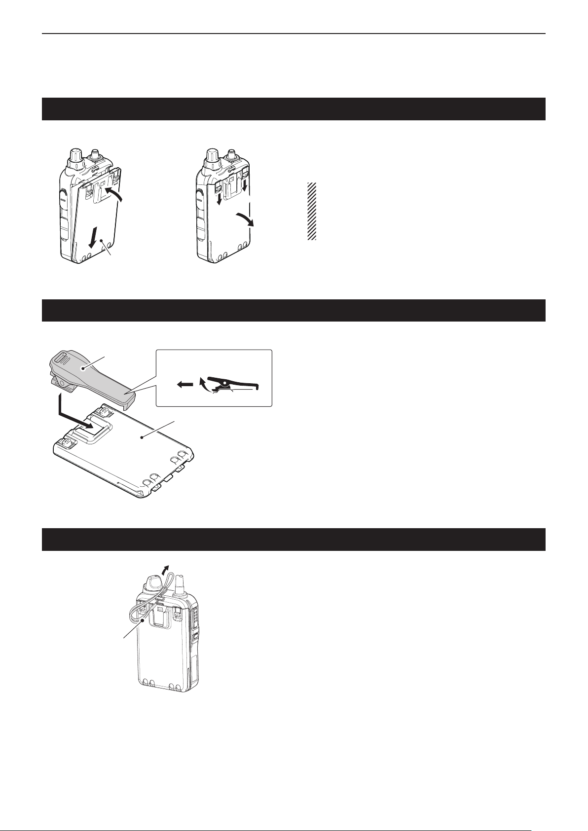
Battery pack
Belt clip
Battery pack or
battery case
To detachTo attach
Belt clip
To detachTo attach
Battery pack (BP-271)
To attach or detach the battery pack:
To attach or detach the battery pack or battery case,
follow the illustrations to the left.
Even when the communication terminal power is
OFF, a small current still flows in the communication
terminal. Remove the battery pack or case when not
using it for a long time. Otherwise, the batteries will
become exhausted.
To attach the belt clip:
Remove the battery pack from the communication q
terminal, if it is attached.
Slide the belt clip in the direction of the arrow until the w
belt clip locks in place, and makes a ‘click’ sound.
To detach the belt clip:
Remove the battery pack from the communication q
terminal, if it is attached.
Lift the tab up ( w q), and slide the belt clip in the direc-
tion of the arrow (w).
Hand strap
Hand strap
To facilitate carrying the communication terminal, slide
the hand strap through the loop on the top of the rear
panel, as illustrated to the left.
1-3
Page 6

Section 2
BATTERY CHARGING
Battery pack cautions .............................................................2-2
Battery cautions D ......................................................................2-2
Charging caution D .....................................................................2-3
Charging time (Approximate) D ..................................................2-3
Using the BC-202 .....................................................................2-4
Using the BC-211 .....................................................................2-4
Battery status indicator ..........................................................2-5
Battery warning beeps D ............................................................2-5
Battery life ................................................................................2-5
Battery case .............................................................................2-6
2-1
Page 7

BATTERY CHARGING
2
Battery pack cautions
RDANGER! NEVER short the terminals (or charg-
ing terminals) of the battery pack. Also, current may flow
into nearby metal objects such as a key, so be careful
when placing battery packs (or the communication terminal) in bags, etc. Simply carrying with or placing near
metal objects may cause shorting. This may damage
not only the battery pack, but also the communication
terminal.
RDANGER! Use and charge only specified Icom
battery packs with Icom terminals or Icom chargers.
Only Icom battery packs are tested and approved for
use with Icom terminals or charged with Icom chargers. Using third-party or counterfeit battery packs may
cause smoke, fire, or cause the battery pack to burst.
Battery cautions D
R
DANGER! DO NOT hammer or otherwise impact
the battery pack. Do not use the battery pack if it has
been severely impacted or dropped, or if the battery
pack has been subjected to heavy pressure. Battery
damage may not be visible on the outside of the case.
Even if the surface of the battery pack does not show
cracks or any other damage, the cells inside the battery
pack may rupture or catch fire.
RDANGER! NEVER use or leave battery pack in
areas with temperatures above +60˚C (+140˚F). High
temperature buildup in the battery, such as could occur
near fires or stoves, inside a sun heated car, or in direct
sunlight may cause the battery pack to rupture or catch
fire. Excessive temperatures may also degrade battery
performance or shorten battery life.
RDANGER! DO NOT expose the battery pack to
rain, snow, seawater, or any other liquids. Do not charge
or use a wet battery pack. If the battery pack gets wet,
be sure to wipe it dry before using.
RDANGER! NEVER incinerate a used battery
pack since internal battery gas may cause it to rupture,
or may cause an explosion.
RDANGER! If fluid from inside the battery gets in
your eyes, blindness can result. Rinse your eyes with
clean water, without rubbing them, and see a doctor
immediately.
RWARNING! Immediately stop using the battery if
it emits an abnormal odor, heats up, or is discolored or
deformed. If any of these conditions occur, contact your
Icom dealer or distributor.
RWARNING! Immediately wash, using clean water,
any part of the body that comes into contact with fluid
from inside the battery.
RWARNING! NEVER put the battery pack in a mi-
crowave oven, high-pressure container, or in an induction heating cooker. This could cause a fire, overheating, or cause the battery pack to rupture.
CAUTION: Always use the battery pack within the
specified temperature range, –20˚C to +60˚C (–4˚F to
+140˚F). Using the battery pack out of its specified temperature range will reduce the battery’s performance
and battery life.
CAUTION: Shorter battery life could occur if the bat-
tery pack is left fully charged, completely discharged,
or in an excessive temperature environment (above
+50˚C; +122˚F) for an extended period of time. If the
battery pack must be left unused for a long time, it must
be detached from the terminal after discharging. You
may use the battery pack until the battery indicator
shows half capacity, then keep it safely in a cool dry
place at the following temperature range:
–20˚C (–4˚F) to +50˚C (+122˚F) (within a month)
–20˚C (–4˚F) to +35˚C (+95˚F) (within three months)
–20˚C (–4˚F) to +20˚C (+68˚F) (within a year)
BE SURE to replace the battery pack with a new one
after five years, even if still holds a charge. The material
inside the battery will deteriorate after a period of time,
even with little use.
RDANGER! NEVER solder the battery terminals,
or NEVER modify the battery pack. This may cause
heat generation, and the battery pack may burst, emit
smoke or catch fire.
RDANGER! Use the battery pack only with the com-
munication terminal for which it is specified. Never use
a battery pack with any other equipment, or for any purpose that is not specified in this instruction manual.
2-2
Page 8

BATTERY CHARGING
2
Battery pack cautions (continued)
Charging caution D
RDANGER! NEVER
areas with extremely high temperatures, such as near
fires or stoves, inside a sun-heated vehicle, or in direct
sunlight. In such environments, the safety/protection
circuit in the battery pack will activate, causing the battery pack to stop charging.
charge the battery pack in
RWARNING! NEVER charge or leave the bat-
tery pack in the battery charger beyond the specified
time for charging. If the battery pack is not completely
charged by the specified time, stop charging and remove the battery pack from the battery charger. Continuing to charge the battery pack beyond the specified
time limit may cause a fire, overheating, or the battery
pack may rupture.
RWARNING! NEVER insert the communication
terminal (with battery pack) into the charger if it is wet
or soiled. This could corrode the battery charger terminals or damage the charger. The charger is not waterproof.
CAUTION: DO NOT charge the battery pack out-
side of the specified temperature range:
BC-202: ±0˚C to +40˚C (+32˚F to +104˚F)
BC-211: +10˚C to +40˚C (+50˚F to +104˚F)
Icom recommends charging the battery pack at +25˚C
(+77˚F). The battery pack may heat up or rupture if
charged out of the specified temperature range. Additionally, battery performance or battery life may be
reduced.
Charging time D (Approximate)
Charger
Battery pack
BP-271 2 hours 2 hours
BP-272 3.5 hours 3.5 hours
BC-202 BC-211
2-3
Page 9

BATTERY CHARGING
Desktop charger
BC-202
AC outlet
Charging
indicator
Battery pack
Communication
terminal
+ battery pack
Tapping screws
3.5×30 mm
Turn OFF the power
Power adapter
AC outlet
Power adapter
(BC-157S)
Multi-Charger
BC-211
Charging indicator
(one for each slot)
Battery pack
Communication terminal
+ battery pack
Turn OFF the power
Guide rail
Ta b
2
Using the BC-202
The BC-202 rapidly charges a battery pack.
Charging time: Approximately 2 hours for the BP-271
Approximately 3.5 hours for the BP-272
The following item is required.
• A power adapter ( A different type, or no power adapter
is supplied, depending on the charger versions.)
• About charging indicator
Lights orange: Charging
Lights green: Charging completed
Blinks orange: See page 7-2.
Using the BC-211
The BC-211 rapidly charges up to 6 battery packs.
Charging time: Approximately 2 hours for the BP-271
Approximately 3.5 hours for the BP-272
The following item is required.
• A power adapter (not supplied with some versions.)
• About charging indicator
Lights orange: Charging
Lights green: Charging completed
Blinks orange: See page 7-2.
IMPORTANT: Battery charging caution
Ensure the guide rails
on the battery pack are
correctly aligned with
the tabs inside the
charger.
2-4
Page 10

BATTERY CHARGING
Power OFF
Blinks
1/23 12:34
All
LOW BATTERY
Blinks
2
Battery status indicator
Indicator Battery status
The battery charge has sufficient capacity.
The battery charge is exhausted a little.
The battery charge is nearing exhaustion.
Charging is necessary. (The communication
terminal can be operated for a short time.)
The battery charge is almost exhausted.
Charging is necessary. (The communication
terminal will quickly become impossible to
operate.)
3 long beeps
sound
Different beeps
sound, then...
The battery status indicator displays the attached
battery pack's (BP-271 or BP-272) remaining battery
charge.
Battery warning beeps D
When the battery charge is almost exhausted, the battery status indicator, “ ,” starts blinking, and warning
beeps sound every 30 seconds. Charge the battery
pack when the beeps begin to sound.
When “LOW BATTERY” is displayed, the communication terminal power will automatically turn OFF soon.
Battery life
BP-271 BP-272
Voltage 7.4 V
Capacity
Battery life
(approximate)
• Duty cycle: TX : RX : Standby = 1 : 1 : 8
1150 mAh
1200 mAh (typical)
(minimum)
27 hours 40 hours
(based on operating style)
1880 mAh (minimum)
2000 mAh (typical)
The approximate battery life (operating time) is shown
to the left.
NOTE:
The battery life decreases if the communication terminal is out of a communication area for a long time,
causing the terminal to continuously search for an
access point (roaming).
2-5
Page 11

BATTERY CHARGING
3 AA (LR6)
Alkaline batteries
BP-273 battery case
(Option)
2
Battery case
• Battery life (approximate)
BP-273: 24 hours*
• Duty cycle: TX : RX : Standby = 1 : 1 : 8
( based on operating
style)
* The battery life may differ, depending the installed alkaline
batteries.
To use the BP-273 battery case, install three AA (LR6)
size alkaline batteries, as described below.
Remove the battery case if it is attached. q
Install three AA (LR6) size alkaline batteries. w
• Install only alkaline batteries.
• Be sure to observe the correct polarity.
Attach the battery case. (p. 1-3) e
A built-in step-up converter in the BP-273 increases
the voltage to 5.5 V DC.
When the BP-273 battery case is used, the battery
status indicator cannot display the battery capacity
of the alkaline batteries. The battery indicator remains like this: “ .” It does not reflect with the true
battery capacity.
CAUTION:
• When installing batteries, make sure they are all
the same brand, type and capacity. Also, do not mix
new and old batteries together.
• Keep the battery terminals clean. It’s a good idea to
occasionally clean them.
• Never incinerate used battery cells since the internal battery gas may cause them to rupture.
• Never expose a detached battery case to water.
If the battery case gets wet, be sure to wipe it dry
before using it.
• Never use batteries whose insulated covering is
damaged.
• Remove the alkaline batteries when battery case is
not used. Otherwise the installed alkaline batteries
will exhausted due to built-in step-up converter.
2-6
Page 12

Section 3
BASIC OPERATION
Turning ON the power .............................................................3-2
Adjust audio level ....................................................................3-2
Key lock function .....................................................................3-3
3-1
Page 13

BASIC OPERATION
Booting . . .
0001
Connecting . . .
0001
Setting up. . .
0001
IP100H
Ver. . /
1/23 12:34
All
Firmware
version
ID
10
3
Turning ON the power
Rotate [PWR/VOL] to turn ON the power. ➥
• A click and beep sound.
Attention!
The explanations in this manual are based on the registration to your IP1000C, system controller has been
completed.
Adjust audio level
(Standby screen)
(Example)
NOTE: When no standby screen is displayed, ask your
system manager.
Rotate [PWR/VOL]. ➥
• A volume level between 0 and 32 is displayed.
3-2
Page 14

BASIC OPERATION
Key lock
1/23 12:34
All
Standby screen
When a locked key is pushed
3
Key lock function
Hold down for
1 second
Turn ON to prevent unnecessary function access.
Hold down [CLR• ➥ ] for 1 second to turn the Key
lock function ON or OFF.
• [PTT] and [PWR/VOL] can be used while the Key lock
function is turned ON.
• When the Key lock function is turned ON and the locked
key is pushed, “Key lock” appears.
3-3
Page 15

Section 4
CALLING OPERATION
Calling procedures outline .....................................................4-2
Selecting address books, and addresses (ID) ......................4-3
Selecting messages or statuses ............................................4-4
Voice communication ..............................................................4-5
Individual call D ...........................................................................4-5
All call D ......................................................................................4-5
Group call D ................................................................................4-5
Telephone call D .........................................................................4-5
Message Call ............................................................................4-6
To an individual terminal D ..........................................................4-6
To all terminals D ........................................................................4-6
To a Group D ...............................................................................4-6
Using a call history..................................................................4-7
Status Call ................................................................................4-8
Erasing all log items ................................................................4-8
Area Call function ....................................................................4-9
4-1
Page 16

CALLING OPERATION
4
Calling procedures outline
[PTT]
[Option]
Select a desired address book. (p. 4-3) q
• Push [ ] one or more times.
• Select “All” for all terminals calls, “Group” for group calls,
“Individual” for individual terminal calls or “Telephone” for
telephone calls.
• Selectable address books may differ, depending on the
IP1000C's settings.
Select a desired address (ID) or extension number. w
(p. 4-3)
• Push [J] or [K] one or more times.
• Selectable IDs or extension numbers may differ, depend-
ing on the IP1000C's settings.
• You can select a desired ID or extension number from the
call history by pushing [
]. (p. 4-7)
If you want to send a message (p. 4-6), or make an e
area call (p. 4-9), push [FUNC] one or more times.
• Select “Message” to transmit a message, or “Area Call”
for an Area Call.
• Push [J] or [K] one or more times to select a desired
message.
• Selectable messages may differ, depending on the
IP1000C's setting.
• When Area Call is selected, push [J] or [K] to select
ON.
Push [PTT] to make a call. r
Hold down [PTT], and speak at your normal voice t
level.
Release [PTT] to listen. y
Repeat the steps u t and y until you finish your con-
versation.
To hang up a telephone call, push [Option]. i
• The function assigned to [Option] may differ, depending
on the IP1000C's settings.
• Ask your system manager which function is assigned.
For your information
When the VOX function or full-duplex mode is set in the
IP1000C, steps t and y are not necessary.
When the VOX function is set, speak into the headset
microphone to transmit, then stop speaking to listen.
In full-duplex, you can speak and hear the other person
at the same times.
4-2
Page 17

CALLING OPERATION
All
All
Group
1000
Sales
Group
2000
Dispatcher
Group
7000
Account
Individual
1001
Reception
Individual
1002
Secretary
Individual
1010
Chief
Telephone
1101
Guard Room
Telephone
3101
Server Room
Telephone
1101
Waiting Room
Push [ ]
Push [J]/[K]
Push [J]/[K]
Push [J]/[K]Push [J]/[K]
Push [J]/[K]
Push
[J]/[K]
Push
[J]/[K]
Push [J]/[K]
Push [J]/[K]
Push [J]/[K]
Push [ ]
Push [ ]
Push [ ]
4
Selecting address books, and addresses (ID)
Push [ q ] one or more times to select a desired ad-
dress book.
• Select “All” for all stations calls, “Group” for group calls,
“Individual” for individual station calls or “Telephone” for
telephone calls.
• Selectable address books may differ, depending on the
IP1000C's settings.
Push [ w J] or [K] one or more times to select a desired
ID or extension number.
• Selectable IDs or extension numbers may differ, depending on the IP1000C's settings.
• Address book and address (ID) selection sequence
4-3
Page 18

CALLING OPERATION
Message
1000
Gather immediate
Message
1000
A message was s
Message
1000
Report the result.
Status
Meeting
Status
Away from the de
Status
Under a break
Area Call
OFF
Area Call
ON
Push [J]/[K]
Push [J]/[K]
Push [J]/[K]
Push [J]/[K]
Push
[J]/[K]
Push
[J]/[K]
Push [J]/[K]
Push [FUNC]
Push
[FUNC]
Push
[FUNC]
desk
sent.
Message
1000
A message was sent.
Status
Away from the desk
• Message select screen • Status select screen
May scroll depending on the
message length.
Displays the address (ID) that was
selected before you pushed [FUNC].
4
Selecting messages or statuses
Push [FUNC] one or more times. q
• Select “Message” to transmit messages, or “Status” to
transmit statuses.
• The “Message” or “Status” item may not be selectable,
depending on the IP1000C's settings.
Push [ w J] or [K] one or more times to select a desired
message or status.
• The selected message or status may scroll, depending
on the message length.
• Selectable message or status may differ, depending on
the IP1000C's settings.
• Message, status and the Area Call function selection sequence
4-4
Page 19

CALLING OPERATION
4
Voice communication
[PTT]
[Option]
Individual call D
Push [ q ] one or more times to select “Individual.”
Push [ w J] or [K] one or more times to select a desired
individual address (ID).
Push [PTT] to call. e
• When your call is successful, “Connected” may be
displayed and beeps may sound, depending on your
IP1000C's settings.
Hold down [PTT] and then speak at your normal r
voice level.
Release [PTT] to listen. t
Repeat the steps y r and t until you finish your con-
versation.
All call D
For your reference
Only one terminal can reply to an All or Group call.
We recommend you to carefully listen for a reply after
you making an All or Group call.
When the VOX function or full-duplex mode is set at
the IP1000C, the [PTT] toggling between transmit and
listen is not necessary.
When the VOX function is set, speak into the headset
microphone to transmit, stop speaking to listen.
In full-duplex, you can speak and hear the other person at the same times.
Push [ q ] one or more times to select “All.”
Push [PTT] to call. w
Hold down [PTT] and say your message at your nor- e
mal voice level.
Release [PTT] to listen. r
Group call D
Push [ q ] one or more times to select “Group.”
Push [ w J] or [K] one or more times to select a desired
group address (ID).
Push [PTT] to call. e
Hold down [PTT] and say your message at your nor- r
mal voice level.
Release [PTT] to listen. t
Telephone call D
Push [ q ] one or more times to select “Telephone.”
Push [ w J] or [K] one or more times to select a desired
extension number (ID).
Push [PTT] to call. e
Wait until reply is heard. r
After the reply, hold down [PTT] and then speak at t
your normal voice level.
Release [PTT] to listen. y
Repeat the steps u t and y until you finish your con-
versation.
To hang up the call, push [Option]. i
4-5
Page 20

CALLING OPERATION
4
Message Call
[PTT]
To an individual terminal D
Push [ q ] one or more times to select “Individual.”
Push [ w J] or [K] one or more times to select a desired
individual address (ID).
Push [FUNC] one or more times to select “Mes- e
sage.”
Push [ r J] or [K] one or more times to select a desired
message.
• The selected message may scroll, depending on the
message length.
Push [PTT] to call. t
• When your message call is successful, “Successful” may
be displayed and beeps may sound, depending on your
IP1000C's settings.
To all terminals D
Push [ q ] one or more times to select “All.”
Push [FUNC] one or more times to select “Mes- w
sage.”
Push [ e J] or [K] one or more times to select a desired
message.
• The selected message may scroll, depending on the
message length.
Push [PTT] to call. r
• When your message call is successful, “Successful” may
be displayed and beeps may sound, depending on your
IP1000C's settings.
To a Group D
Push [ q ] one or more times to select “Group.”
Push [ w J] or [K] one or more times to select a desired
group address (ID).
Push [FUNC] one or more times to select “Mes- e
sage.”
Push [ r J] or [K] one or more times to select a desired
message.
• The selected message may scroll, depending on the
message length.
Push [PTT] to call. t
• When your message call is successful, “Successful” may
be displayed and beeps may sound, depending on your
IP1000C's settings.
4-6
Page 21

CALLING OPERATION
Tx log
1/23 12:34
Reception
Tx log
1/23 10:23
Reception
Tx log
1/22 15:25
Sales
Tx MSG log
1/23 16:03
Dispatcher Are
Tx MSG log
1/23 11:24
Sales Gather i
Tx MSG log
1/22 8:25
Chief Away fro
Rx MSG log
1/23 16:35
Chief Report th
Rx MSG log
1/23 9:56
Reception Give
Rx MSG log
1/20 8:33
Secretary A me
Tx TEL log
1/23 9:03
Guard Room
Tx TEL log
1/22 9:01
Guard Room
Tx TEL log
1/12 9:04
Guard Room
Rx TEL log
1/23 19:55
Guard Room
Rx TEL log
1/23 14:32
Server Room
Rx TEL log
1/20 12:05
Waiting Room
Push [J]/[K]
Push [J]/[K]
Push
[J]/[K]
Push [J]/[K]
Push [J]/[K]
Push [J]/[K]
Push [J]/[K]
Push [J]/[K]
Push [J]/[K]
Rx log
1/23 12:35
Reception
Rx log
1/23 10:24
Reception
Rx log
1/21 9:55
Chief
Push [J]/[K]
Push [J]/[K] Push [J]/[K]
Push [J]/[K] Push [J]/[K]
Push [J]/[K] Push [J]/[K]
Push [J]/[K] Push [J]/[K]
Push
[ ]
Push
[ ]
Push
[ ]
Push
[ ]
Push
[ ]
Push
[ ]
4
Using a call history
[PTT]
You can make a call using previously transmitted and
received call settings.
Up to 10 calls can be stored in each TX log, RX log, TX
message log, RX message log, TX telephone log and
RX telephone log.
Push [ q ] one or more times to select a desired his-
tory log.
• Tx log: Transmitted call
• Rx log: Received call
• Tx MSG log: Transmitted message
• Rx MSG log: Received message
• Tx TEL log
: Transmitted telephone
• Rx TEL log: Received telephone
Push [ w J] or [K] one or more times to select a desired
log call.
Push [PTT] to call. e
• History selection sequence
4-7
Page 22

CALLING OPERATION
SET
LOG CLR
SET
LOG – – –
Push [J]/[K]
4
Status Call
[PTT]
Push [FUNC] one or more times to select “Status.” q
Push [ w J] or [K] one or more times to select a desired
status.
• The selected status may scroll, depending on the message length.
Push [PTT] to call. e
• When your status call is successful, “Successful” may
be displayed and beeps may sound, depending on your
IP1000C's settings.
For your information
A transmitted your status can only be confirmed with
your IP1000C system controller or IP100FS remote
communicator. Not for an individual IP100H communication terminal.
Erasing all log items
All items in the Tx log, Rx log, Tx MSG log, Rx MSG log,
Tx TEL log and Rx TEL log, can be manually erased,
if desired.
Turn OFF the communication terminal if it is ON. q
While holding down [FUNC], turn ON the power. w
• When “SET” is displayed, release [FUNC].
Push [ e J] or [K] one or more times to select “CLR.”
Push [ r ].
• “ Deleting…” is displayed, then the IP100H automatically
reboots.
4-8
Page 23

CALLING OPERATION
1/23 12:34
All
Displayed when the Area
Call function is ON.
4
Area Call function
The Area Call function allows you to call the areas that
the selected wireless access points cover.
The Area Call function may or may not be enabled, and
the areas you can call depends on your IP1000C's settings.
Push [FUNC] one or more times to select “Area q
Call.”
Push [ w J] or [K] to select ON.
Push [CLR• e ] to return to the standby screen.
• “ ” is displayed.
When an area call is received
“ ” is displayed for a while even if the area call is set to
OFF.
4-9
Page 24

Section 5
OTHER FUNCTIONS
Pocket beep function ..............................................................5-2
P-Bell function .........................................................................5-2
About the [Option] switch .......................................................5-2
5-1
Page 25

OTHER FUNCTIONS
1/23 12:34
All
1/23 12:34
All
Blinks
1/23 12:34
All
Displays
5
Pocket beep function
Standby screen When a call is received
P-Bell function
Standby screen
The Pocket beep function sounds beeps and blinks the
“ ” icon to let you know a call is being received.
• This function is set by your IP1000C system controller.
The P-Bell function sounds beeps to let you know a call
is being received.
However, you cannot listen to the call until you answer
it.
Push [PTT] to answer the call, then listen to the caller.
•
• The “ ” icon is displayed when the P-Bell function is
used.
• This function is set by your IP1000C system controller.
About the [Option] switch
[Option]
One of the following functions may be assigned to the
[Option] switch by your IP1000C system controller.
• Message select: Selects often used messages.
• One touch call select: Selects often used call types
with an address.
( either All, Group, Individual or
Telephone)
• Clear down: Hangs up a telephone call.
Ask your system manager which function is assigned.
5-2
Page 26

Section 6
OPTIONS
Option list .................................................................................6-2
Battery packs/case D ..................................................................6-2
Battery chargers D ......................................................................6-2
Others D ......................................................................................6-2
Headset/Microphones D .............................................................6-2
Connection ...............................................................................6-3
Connectable options D ................................................................6-3
6-1
Page 27

OPTIONS
6
Option list
Battery packs/case D
BP-271/BP-272 • l
BP-271: 7.4 V/1150 mAh (min.), 1200 mAh (typ.)
BP-272: 7.4 V/1880 mAh (min.), 2000 mAh (typ.)
BP-273 •
For LR6 (AA) × 3 alkaline batteries
b a t t e r y c a s e
i-ion
b a t t e r y p a c k s
Battery chargers D
BC-202 • d e s k t o p c h a r g e r + BC-123S a c a d a p t e r
BC-211 • m u lt i -c h a r g e r + BC-157S a c a d a p t e r
Rapidly charges Li-ion battery pack.
Charging time: Approximately 2 hours for the BP-271
Approximately 3.5 hours for the BP-272
Others D
LC-181 • c a r r y i n g c a s e
MB-127 • b e l t c l i p
SP-13 • e a r p h o n e + OPC-2144 a d a p t e r c a b l e
Headset/Microphones D
H M - 1 5 3 • e a r p h o n e m i c r o p h o n e
+ OPC-2144 a d a p t e r c a b l e
H M - 1 6 6 • e a r p h o n e m i c r o p h o n e
+ OPC-2144 a d a p t e r c a b l e
HM-153LS/HM-166LS • e a r p h o n e m i c r o p h o n e s
H M - 1 8 6 • s p e a k e r -m i c r o p h o n e
+ OPC-2144 a d a p t e r c a b l e
HM-186LS • s p e a k e r -m i c r o p h o n e
For simplex operation
HS-85 •
HS-94/HS-95 • h e a d s e t s /HS-97 t h r o a t m i c r o p h o n e
+ OPC-2006LS a d a p t e r c a b l e
HS-94: Ear-hook type
HS-95: Neck-arm type
OPC-2006LS: For VOX operation
v o x u n i t + OPC-2144 a d a p t e r c a b l e
/OPC-2328 p t t s w i t c h c a b l e
6-2
Page 28

OPTIONS
Jack cover
6
Connection
Connectable options D
HM-153LS/HM-153*
e a r p h o n e m i c r o p h o n e
Be sure to turn power OFF before connecting or disconnecting optional equipment to or from the [ / ]
jack.
CAUTION: Attach the jack cover when optional
equipment is not used.
1
HM-166LS/HM-166*
e a r p h o n e m i c r o p h o n e
1
HM-186LS/HM-186*
s p e a k e r -m i c r o p h o n e
1, *2
HM-153LS
HS-85*
v o x u n i t
HS-97*
t h r o a t m i c r o p h o n e
1, †1
3, *4, †2
HM-166LS
HS-94*
h e a d s e t (Ear-hook type)
SP-13*
e a r p h o n e
3, *4, †2
1
HM-186LS
HS-95*
h e a d s e t (Neck-arm type)
3, *4, †2
*1 OPC-2144 is required.
2
*
For simplex operation
3
*
OPC-2006LS is required for VOX op-
eration.
4
*
OPC-2328 is required for PTT switch
operation.
†
1
Disables the VOX function in your
IP1000C setting.
†
2
To use the VOX function, enables the
VOX function in your IP1000C set-
ting.
6-3
Page 29

Section 7
FOR YOUR REFERENCE
Troubleshooting .......................................................................7-2
Specifications ..........................................................................7-3
IP100H D ....................................................................................7-3
BC-202 D d e s k t o p c h a r g e r ......................................................7-3
BC-211 D m u l t i -c h a r g e r ...........................................................7-3
7-1
Page 30

FOR YOUR REFERENCE
7
Troubleshooting
The following chart is designed to help you correct
problems which are not equipment malfunctions.
PROBLEM POSSIBLE CAUSE SOLUTION REF.
No power comes ON. The battery charge is exhausted.•
Loose connection of the battery pack •
(case).
No sound comes from the
speaker.
No reply is received Too far from an access point.•
“Key l ock” i s displayed
when a key is pushed
Cannot charge the battery
pack completely
Th e chargin g ind icat or
blinks orange, or alternately
blinks orange and green
The “
“Connecting…” is displayed
( standby screen won't be
displayed)
” icon blinks, or
Volume level is too low.• Rotate [PWR/VOL] to adjust to a desired •
The “•
” icon blinks.
The operator is away from the terminal, or •
the terminal is turned OFF.
The Key Lock function is turned ON.•
The communication terminal power is •
ON.
The battery pack is not properly inserted.•
Charging the battery pack outside of the •
chargeable temperature range.
Loose connection of charging terminals.•
The communication terminal power is •
ON.
SSID Broadcast function is ON in an ac-•
cess point (when 5 GHz band is used).
Too far from an access point.•
Access point power is OFF.•
If you are unable to locate the cause of a problem, or
solve it through the use of this chart, contact your nearest Icom Dealer or Service Center.
Charge the battery pack, or replace the •
batteries.
Clean battery pack (case) terminals.•
level.
Move your location, then try again.•
Wait until the operator is back, or ask sys-•
tem manager about the status.
Hold down [CLR••
turn the Key Lock function OFF.
Turn OFF the power.• p. 2-4
Insert the battery pack properly.•
Charge the battery pack in the charge-•
able temperature range:
BC-202: 0°C to 40°C (+32°F to +104°F)
BC-211:
Clean the charging terminals.•
Turn OFF the power.•
Ask your system manager about the ac-•
cess point settings.
Move your location, then try again.•
Turn ON the access point power.•
10°C to 40°C (+50°F to +104°F)
] for 1 second to
pp. 2-4
2-6
–
p. 3-2
–
–
p. 3-3
p. 2-4
p. 2-3
–
p. 2-4
–
–
–
7-2
Page 31

FOR YOUR REFERENCE
7
Specifications
IP100H D
Power supply requirement:•
Icom BP-271, BP-272 battery pack or
BP-273 battery case
Current drain:•
Less than 150 mA average
( Tx: 100 mA, Rx: 150 mA,
standby: 50 mA)
Usable temperature range:•
–10°C to +60°C (+14°F to +140°F)
Dimensions: • 58(W) × 95(H) × 26.4(D) mm
(2.3(W) × 3.7(H) × 1.0(D) inches)
(projections are not included)
Weight: • Approximately 205 g (7.2 oz)
(with antenna and BP-271)
Wireless LAN standard:•
IEEE802.11 n/a/b/g
Authentication and Encryption:•
WEP (64/128 bit),
WPA-PSK (TKIP/AES),
WPA2-PSK (TKIP/AES)
Protocol: • TCP/IP
Communication range:•
Frequency band Internal antenna External antenna
2.4 GHz band
5 GHz band 190 m (623 ft)
(Approximate)
90 m (295 ft)
160 m (525 ft)
BC-202 D d e s k t o p c h a r g e r
Power supply requirement:•
12 to 16 V DC or the specified Icom
power adapter
Charging temperature range:•
0˚C to +40˚C (+32˚F to +104˚F)
Weight: • Approximately 104 g; 3.7 oz
(without power adapter)
Dimensions: • 88(W) × 72.6(H) × 46.5(D) mm
(3.5(W) × 2.9(H) × 1.8(D) inches)
(projections are not included)
BC-211 D m u l t i -c h a r g e r
Power supply requirement:•
12 to 16 V DC or the specified Icom
power adapter
Charging temperature range:•
10˚C to +40˚C (+50˚F to +104˚F)
Weight: • Approximately 1200 g; 2.6 lb
(without power adapter)
Dimensions: • 303.2(W) × 78.2(H) × 179.7(D) mm
(11.9(W) × 3.1(D) × 7.1(H) inches)
(projections are not included)
Audio codec: • G.711 μ-law (64 kbps)
Audio output power:•
Internal speaker
More than 400 mW
(at 10% distortion into a 16 Ω load)
External speaker
More than 200mW
(at 10% distortion into an 8 Ω load)
Audio output impedance:•
Internal speaker
16 Ω
External speaker
8 Ω
7-3
Page 32

A-7120-2EX
© 2014 Icom Inc.
1-1-32 Kamiminami, Hirano-ku, Osaka 547-0003, Japan
 Loading...