

Page 1
INSTRUCTION MANUAL
IP ADVANCED RADIO SYSTEM
CONTROLLER
IP1000C
INTRODUCTION
1 BEFORE USING THE IP1000C
2 SETTING UP THE IP1000C SYSTEM
3 OTHER BASIC FUNCTIONS
4 ABOUT THE SETTING SCREEN
5 MAINTENANCE
6 FOR YOUR INFORMATION
Page 2

INTRODUCTION
Thank you for choosing this Icom product. The IP1000C ip advanced radio system controller is designed and
built with Icom’s IP network technology.
We hope you agree with Icom’s philosophy of “technology first.” Many hours of research and development went
into the design of your IP1000C.
ALL RIGHTS RESERVED. This document contains material protected under International and Domestic
Copyright Laws and Treaties. Any unauthorized reprint or use of this material is prohibited. No part of this
document may be reproduced or transmitted in any form or by any means, electronic or mechanical, including
photocopying, recording, or by any information storage and retrieval system without express written permission
from Icom Incorporated.
All stated specifications and design are subject to change without notice or obligation.
Icom, Icom Inc. and the Icom logo are registered trademarks of Icom Incorporated (Japan) in Japan, the United
States, the United Kingdom, Germany, France, Spain, Russia, Australia, New Zealand, and/or other countries.
Microsoft and Windows are registered trademarks of Microsoft Corporation in the United States and/or other
countries.
All other products or brands are registered trademarks or trademarks of their respective holders.
i
Page 3

INTRODUCTION
FEATURES
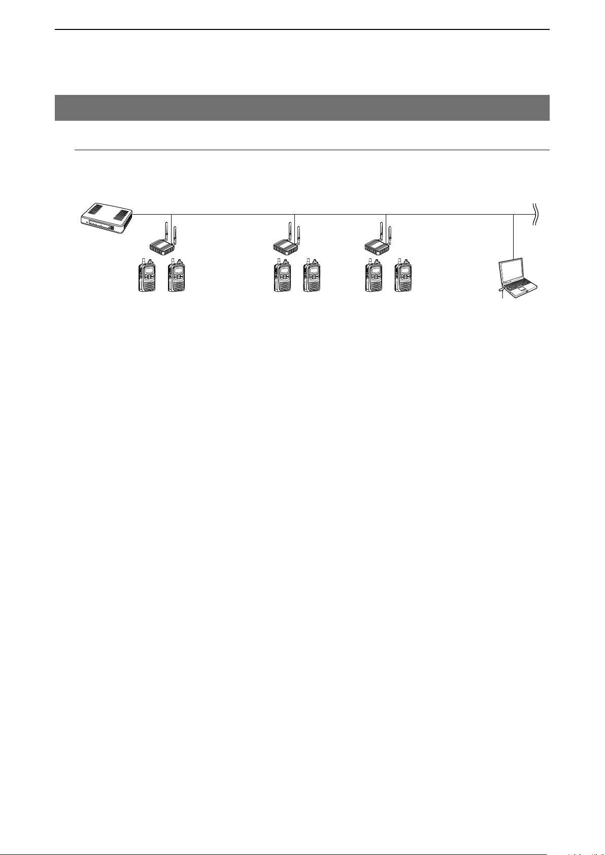
• The IP1000C enables you to communicate through IP networks by using the IP1000C as a controller for the IP100H.
- A wireless access point is required.
Connection example
IP100H
• A total of up to 100 IP100Hs ip communication terminal and IP100FSs remote communicator can be registered and used in
the IP1000C system. (Depending on the IP1000C versions, only 20 terminals can be registered.)
- The IP100FS enables you to remotely communicate with IP communication terminals connected to your IP1000C from
a PC through an IP network.
• The IP1000C has two methods of communications (Simplex and Full-Duplex.)
- The Simplex is for communications where receptions and transmissions are done alternately one by one, and the Full-
Duplex is for simultaneous receptions and transmissions as a telephone call.
• The call types are All Call, Group Call, Talkgroup Call, Individual Call, and Telephone Call.
- The Talkgroup Call is the terminal selects the group that it belongs to.
• In the All Call, Group Call and Talkgroup Call, you can assign the simplex or full-duplex mode to the each calls.
• The Area Calls can be operated by limiting to a certain area.
• If you connect with Icom’s VE-PG3 (ver. 1.13 or later), you will be able to communicate with certain types of Icom trans
ceivers. Also If you connect in bridge port with Icom’s VE-PG3 (ver. 1.03 or later), you will be able to communicate using
the VoIP router, which enables you make extension phone calls and outline phone calls.
- Only the VE-PG3’s bridge ports that are set in the converter mode are connectable.
• A total of up to 50 ID list and 10 messages can be programmed for each setting group.
• Status settings can be programmed to send the status information (Example: Away from the desk) from the IP100H.
- Up to 10 statuses can be programmed.
• The settings configured with the IP1000C is automatically set when the IP100H is turned ON.
• Automatic firmware updates for the IP100H can be done using the IP1000C.
• The LAN ports automatically select from 10BASE-T, 100BASE-TX or 1000BASE-T, and detect the port polarity type
between MDI (straight) and MDI-X (crossover), depending on the connected devices.
• The [LAN] port is equipped with 4-port switching HUB.
• Supports SNMP as the network management.
• Automatic Restore using a USB flash drive.
• You can communicate with IP100Hs connected to the additional IP1000Cs on the network by using the [Additional Con
troller Link] function.
- Use a VPN router such as Icom’s SR-VPN1 between sites if necessary.
Wireless
access
point
Network
IP1000C
IP
IP100FS
(Remote Communicator)
-
-
*This document is described based on the IP1000C firmware version 2.10.
ii
Page 4

INTRODUCTION
OPTIONS
OPC-1402A
Maintenance cable
IP100FS
Remote communicator
IP100FS enables you to remotely communicate
with IP communication terminals connected to your
Controller from a PC through an IP network.
As of February 2018
NOTE:
Approved Icom optional equipment is designed for optimal performance when used with an Icom transceiver.
Icom is not responsible for the destruction or damage to an Icom device in the event the Icom device is used with equip
ment that is not manufactured or approved by Icom.
NETWORK AND SYSTEM DEFAULT SETTINGS
Menu Item Setting Window Setting Item Item Name Value
Network Settings IP Address IP Address IP Address 192.168.0.1
Subnet Mask 255.255.255.0
DHCP Server DHCP Server DHCP Server Disable
Management Administrator Administrator Username admin (fixed)
Current Password: admin (lower case)
Date and Time
USB USB
Firmware Update Automatic Update Automatic Update Enable
NTP NTP Client Enable
SNTP Server SNTP Server Enable
USB Flash Drive Enable
Firmware Update
USB Access
Permission
✓
Backup/Restore
✓
-
• See the Section 4 for more details on above settings.
• The Administrator’s Username (admin) cannot be changed.
To prevent unauthorized access
You must choose a strong password and change it occasionally.
• Choose one that is not easy to guess.
• Use numbers, characters and letters (both lower and upper case).
iii
Page 5

INTRODUCTION
SETTING PROCEDURE
Set up the IP1000C, following the procedure below.
Step.1
Step.2
Step.3
Step.4
Step.5
Step.6
Connect to a PC and turn ON the power CONNECTION GUIDE
▼
Access the setting screen CONNECTION GUIDE/Section 2
▼
Configuring the network connection pp. 4-11, 4-12
▼
Registering the terminals pp. 2-5, 2-6
▼
Configuring the settings for each terminals p. 2-7
▼
Registering the terminals to a group p. 2-8
▼
Step.7
Configuring the settings for groups pp. 2-9 to 2-14
iv
Page 6

BEFORE USING THE IP1000C
1. Panel description ………………………………………………………………………………………………………………………… 1-2
M Front panel …………………………………………………………………………………………………………………………… 1-2
M Rear panel …………………………………………………………………………………………………………………………… 1-4
2. Feature description ……………………………………………………………………………………………………………………… 1-5
M About the basic connection ………………………………………………………………………………………………………… 1-5
M Connecting transceivers …………………………………………………………………………………………………………… 1-6
M Connecting a telephone and transceivers ………………………………………………………………………………………… 1-6
M Simplex and Full-Duplex …………………………………………………………………………………………………………… 1-7
M Multi communication ………………………………………………………………………………………………………………… 1-7
M All Call and Group Call ……………………………………………………………………………………………………………… 1-8
M Talkgroup Call ………………………………………………………………………………………………………………………… 1-9
M Individual Call ………………………………………………………………………………………………………………………… 1-10
M Calling mode ………………………………………………………………………………………………………………………… 1-10
M Priority Call and its priority ………………………………………………………………………………………………………… 1-11
M Area Call ……………………………………………………………………………………………………………………………… 1-12
M Messages …………………………………………………………………………………………………………………………… 1-13
M About Status Settings ……………………………………………………………………………………………………………… 1-14
Section
1
1-1
Page 7
BEFORE USING THE IP1000C
qwer tyu
1
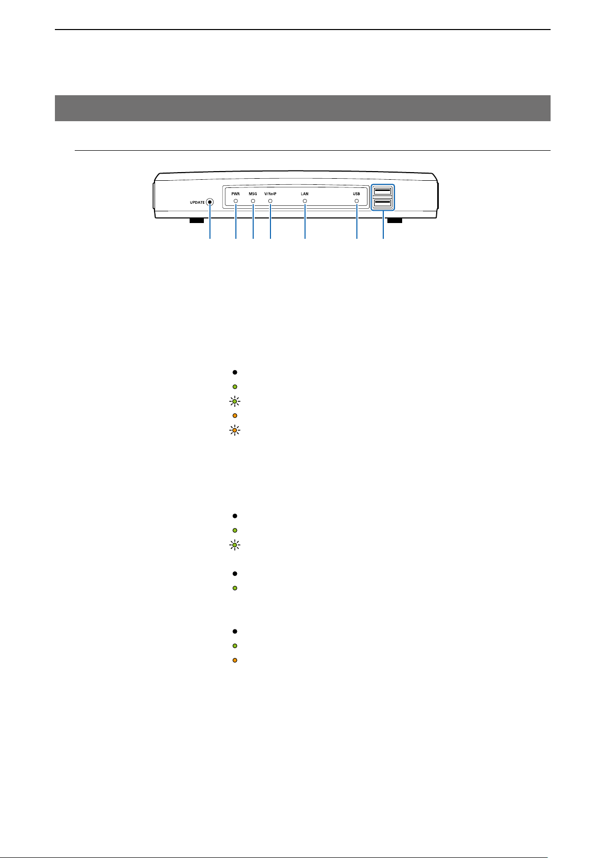
1. Panel description
M Front panel
q [UPDATE] button ………… When [MSG] lights green, a firmware update is ready.
To download and install the new firmware, hold down this button until [MSG]
blinks.
• To use the Firmware Update function, an internet connection, DNS and
default gateway settings are necessary.
w [PWR] ………………………
No light: Power is OFF
Lights green: Power is ON*
Blinks green: Booting*1*2
Lights orange: Booting*
Blinks orange: Booting*1*
*1 After the power is ON:
Blinks green > lights orange > blinks orange > lights green
2
After [INIT] is pushed until the default resets are completed:
*
Blinks orange and green alternately.
e [MSG] ………………………
No light: The latest firmware is installed
Lights green: A firmware update is ready (Online update)
Blinks green: Downloading new firmware (Online update)
r [V/RoIP] ……………………
No light: No registration
Lights green: IP communication terminal registered
3*4
t [LAN]*
…………………… No light: Not connected
Lights green: LAN connected: All connections (1000BASE-T)
Lights orange: LAN connected: More than 1 connection
(10BASE-T/100BASE-TX)
1
1
2
(More than 1 registration)
3
When 1000BASE-T/10BASE-T/100BASE-TX are mixed, the [LAN] LED
*
lights orange.
4
*
The data communication status for each [LAN] port can be checked with
the [LAN] LED on the rear panel. (p. 1-4)
1-2
Page 8
BEFORE USING THE IP1000C
qwer tyu
1
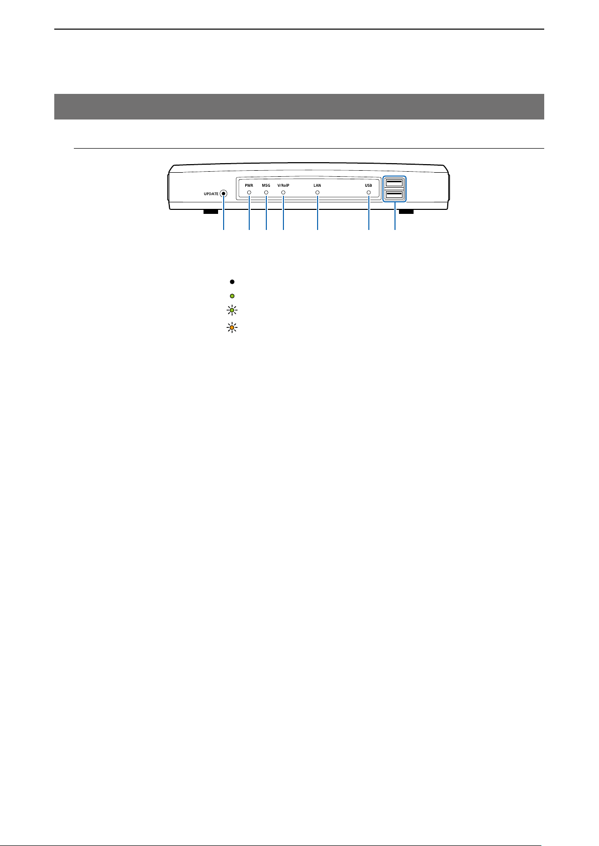
1. Panel description
M Front panel (continued)
y [USB] ……………………… No light: A USB flash drive is not inserted.
Lights green: Inserting an USB flash drive.
Blinks green: Accessing the USB flash drive*
Blinks orange: Accessing the USB flash drive*5
*5 While accessing (resetting or firmware updating) the USB flash drive, this LED
alternately blinks green and orange.
5
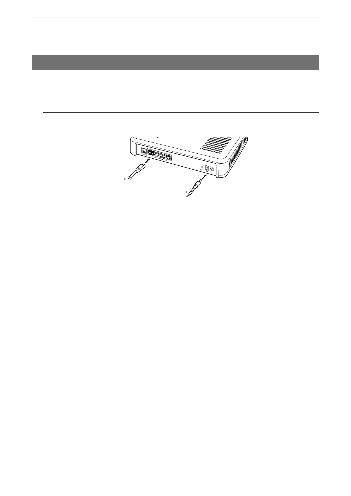
u [USB] ports ……………… If you insert the USB flash drive, the automatic load function for setting data
(USB2.0×2)
can be used. When using the USB flash drive, detach the supplied power
adapter, and then securely insert the USB flash drive into the [USB] port.
• Icom is not responsible for all the devices used with the USB flash drive.
Using the Automatic Setting data upload with a USB flash drive
• Turn OFF the IP1000C’s power before inserting or removing the USB flash
• Either one of the USB slots accepts a USB flash drive, but insert only one
• Securely insert the USB flash drive.
• NEVER remove the USB flash drive or turn OFF the IP1000C’s power, while
• After the firmware updating is completed, check the firmware version on the
• When importing setting data from the USB flash drive to the IP1000C, the
• A USB flash drive such as one with biometric authentication, or one with
Insert a USB flash drive (purchase separately) to recover the configuration or
to update the firmware.
drive, to prevent data corruption.
drive at a time.
transferring data. It will cause data corruption, or damage the USB flash drive.
setting window to verify that the update was correctly done.
originally programmed setting data is automatically saved as “bakdata.sav”
on the USB flash drive, as a backup.
password protection is not supported.
(p. 5-9)
1-3
Page 9
BEFORE USING THE IP1000C
qw ert
1
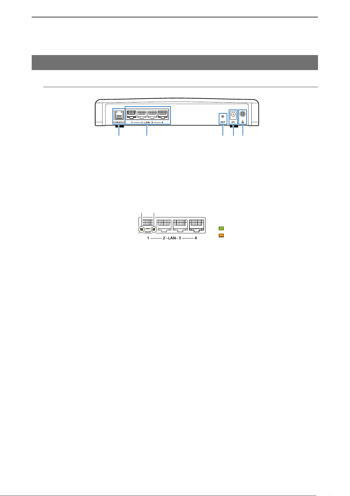
1. Panel description (continued)
M Rear panel
q [CONSOLE] port ………… Connect an RS-232C serial communication interface to externally configure
(RJ-11 type)
w [LAN] ports ……………… Connect the network devices such as a HUB.
(RJ-45 type×4)
the IP1000C. (Optional OPC-1402A is required.)
[LED indication]
q w
Lights: LAN connected
Blinks: LAN data communicating
Green
q
Orange :
w
e [INIT] button ……………… If you forget its IP address and you cannot access to the IP1000C setting
screen, you can initialize (reset) the IP1000C by pushing [INIT] on the rear
panel. (p. 5-4)
• See the “PRECAUTIONS” leaflet for details.
• Initializing resets all settings to the factory defaults.
r DC jack …………………… Connect the supplied power adapter.
t Ground terminal ………… Connect to the ground.
1000BASE-T
:
10BASE-T/100BASE-TX
1-4
Page 10
BEFORE USING THE IP1000C
1
2. Feature description
M About the basic connection
The IP1000C enables you to communicate through IP networks by using the IP1000C as a Controller for the
IP100H.
• A wireless access point is required
IP1000C
IP100H (IP communication terminal)
IP100H enables you to communicate using the IP1000C and a wireless access point through IP networks.
• Verify the appropriate system formation according to the environment used, and then the IP communication terminal confir-
mation, wireless LAN settings and server settings using the CS-IP100H are required.
• See the IP100H instruction manual for more details.
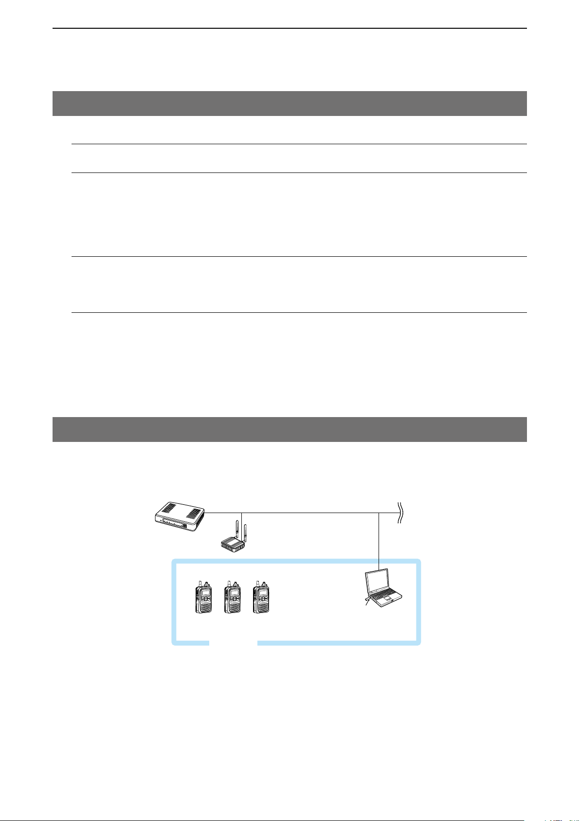
IP100FS (Remote communicator)
The IP100FS enables you to remotely communicate with IP communication terminals connected to your IP1000C
from a PC through IP networks.
• See the IP100FS help file for more details.
CS-IP100H (Cloning software)
The CS-IP100H cloning software is designed to be used for data entry, setting and programming for the IP100H
from a PC. (You can download the free software from the Icom’s website)
• Connect the cloning cables correctly according to the CS-IP100H instruction manual uploaded on the Icom’s website. Read
the instruction carefully and completely.
Wireless access point
IP100H
IP100FS
(Remote communicator)
1-5
Page 11
BEFORE USING THE IP1000C
1
2. Feature description (continued)
M Connecting transceivers
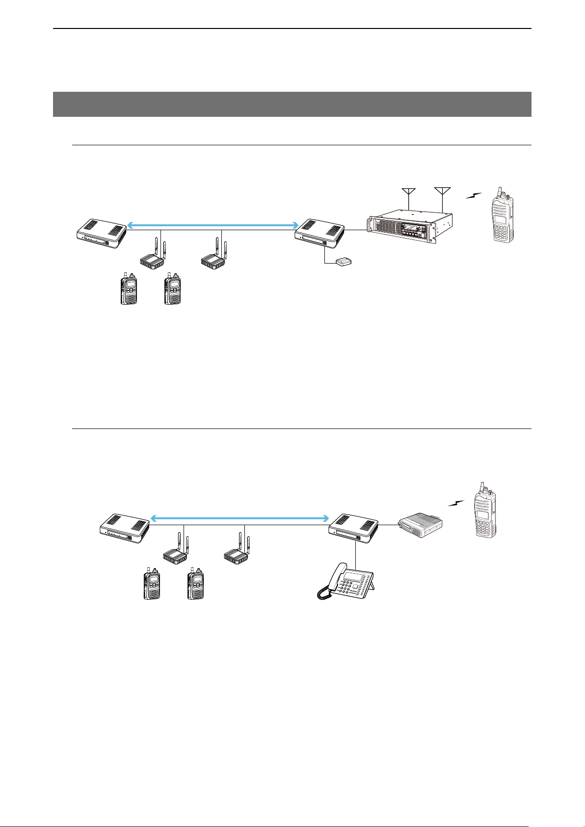
If you connect in controller connection with Icom’s VE-PG3 (ver. 2.01 or later), you will be able to communicate
with certain types of our transceivers.
Controller connection
P
0
P
1
P
2
P
3
P
IP1000C
VE-PG3
(RoIP Gateway)
[USB]
[D-TRX1]
4
Repeater
Transceiver
Wireless access point
CT-24
IP100H
* Only the VE-PG3’s controller ports that are set as the bridge mode are connectable.
M Connecting a telephone and transceivers
If you connect in bridge connection with Icom’s VE-PG3 (ver. 1.13 or later), you will be able to communicate with
certain types of our transceivers and also, using the VoIP router enables you make extension phone calls and out
line phone calls.
Transceiver
[TRX1]
Transceiver
IP1000C
Bridge connection
VE-PG3
(RoIP Gateway)
-
Wireless access point
IP100H
* Only the VE-PG3’s bridge ports that are set as the converter mode are connectable.
1-6
IP phone
Page 12
BEFORE USING THE IP1000C
Simplex and Full-Duplex
1
2. Feature description (continued)
M Simplex and Full-Duplex
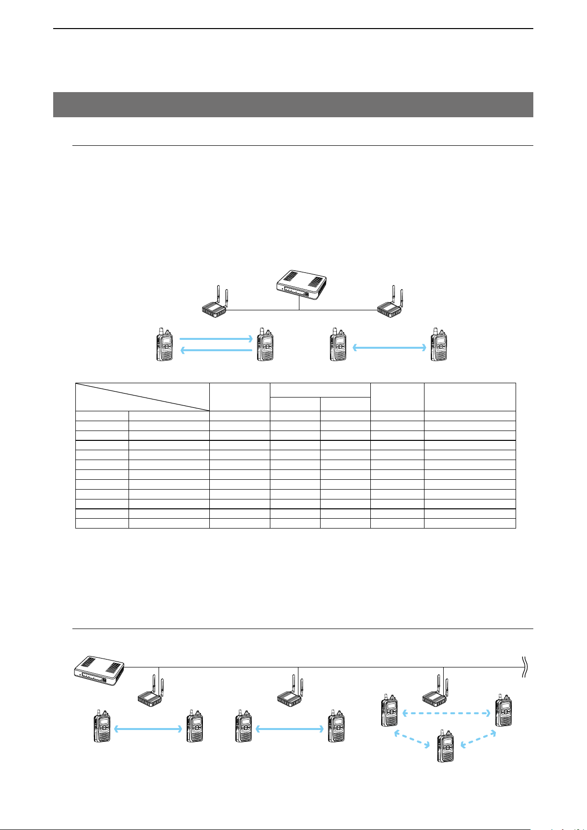
The IP1000C has two methods of communications (Simplex and Full-Duplex.)
The Simplex is for communications where receptions and transmissions are done alternately one by one, and the
Full-Duplex is for simultaneous receptions and transmissions as a telephone call.
Set the Communication Method in “Transceiver Settings” for each IP communication terminal registered to the
IP1000C.
• The Full-Duplex communications are done by connecting a microphone (purchase separately) to the IP100H.
• If no microphone is connected to the IP100H, the communication method is automatically set as Simplex.
IP1000C
Wireless
access point
Simplex
Full-Duplex
IP100H
Connection cables
HM-153 earphone microphone OPC-2144
HM-153LS
HM-166
HM-166LS
HM-183LS
HM-186
HM-186LS
HS-85
HS-94 headset OPC-2006LS
HS-95
HS-97
HS-102
earphone microphone —
earphone microphone OPC-2144
earphone microphone —
speaker microphone —
speaker microphone OPC-2144
speaker microphone —
vox unit OPC-2144
headset OPC-2006LS
throat microphone OPC-2006LS
headset OPC-2359
*3
Full-Duplex
Hands free PTT operation
✓ ✓
✓ ✓
✓ ✓
✓ ✓
✓ ✓ ✓
✓ ✓ ✓
Simplex
✓
✓
✓
✓
✓
✓
IP100H VOX function
(Set in the IP1000C)
—
—
—
—
—
—
—
Disable
Enable
Enable
Enable
Enable
*1
*2
*1 When a headset that supports the VOX function is connected, the communication mode automatically changes be-
tween reception and transmission by verifying the communication voice.
2
*
Select [VOX] on the HS-85.
3
*
Receive by using the OPC-2359.
M Multi communication
To prevent a crosstalk in the IP network, simultaneous multiple communications can be made in the system.
IP1000C
IP100H
Wireless
access point
Individual CallIndividual Call
Group Call
1-7
Page 13
BEFORE USING THE IP1000C
Simplex operation
• When the Simpex is selected, the called station cannot reply until the caller station
Full-duplex operation
1
2. Feature description (continued)
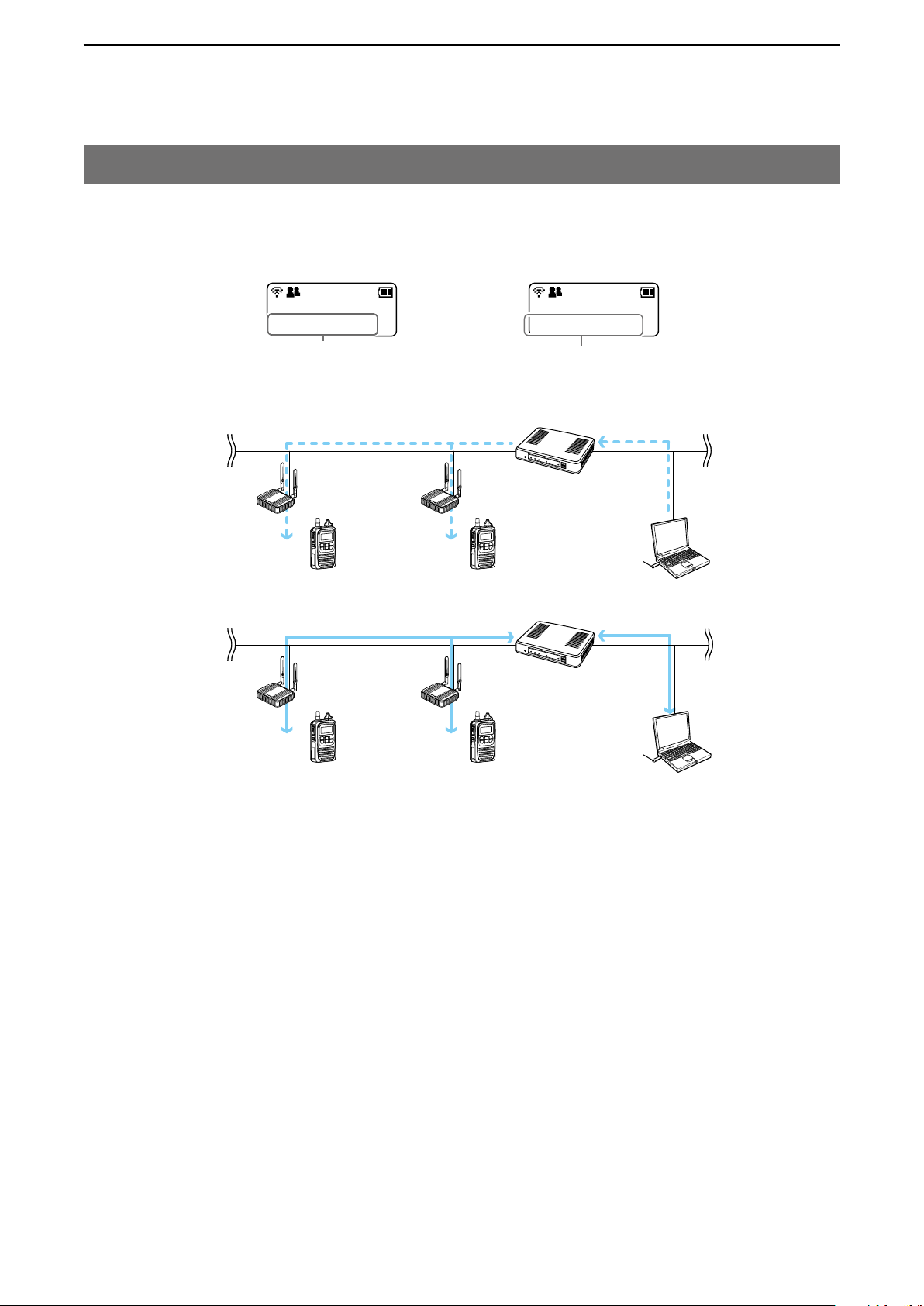
M All Call and Group Call
Simplex or Full-Duplex communication can be set for the All Call and Group Call.
10/8 16:57
All
Selecting All Call
stops transmitting.
Wireless access point
IP100H IP100H IP100FS
Wireless access point
IP100H
IP100H
10/8 16:57
Sales Group1
Selecting Group Call
IP1000C
(Remote communicator)
IP1000C
(Remote communicator)
IP100FS
About All Calls
The All Call function is used to call all the IP100H and IP100FS that are registered in the Transceiver Registration
window in the IP1000C.
About Group Calls
The Group Call function is used to call the desired group selected from the ID List.
• It is required to divide the registered IP100H and IP100FS in the [Transceiver Registration] screen into groups in
the [Destination Settings] screen.
• The ID List and the destination settings set in the IP1000C are commonly used in each group that the IP100H
and IP100FS belong to.
1-8
Page 14
BEFORE USING THE IP1000C
1
2. Feature description (continued)
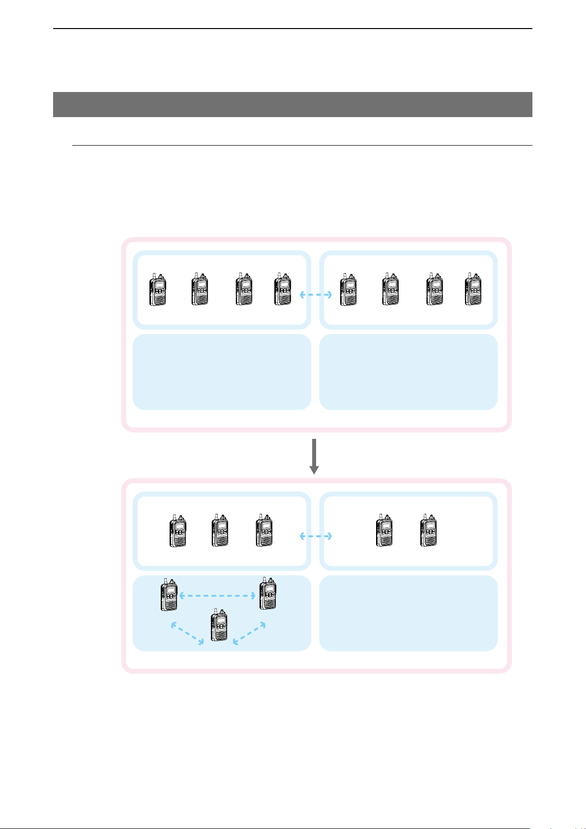
M Talkgroup Call
The Talkgroup Call function allows user to select the group that belong to it from previously registered groups in the
IP1000C.
When users select Talkgroup 1000, terminals are excluded from the original groups, as illustrated below.
When Talkgroup is OFF
0001 0002 0003
All
When Talkgroup is selected
Group 0100
Talkgroup 1000
Group 0100
Group 0101
0004 0006 0007 0008 0009
Talkgroup 1001
Group 0101
0001 0002 0003
Talkgroup 1000
0004
All
0009
0006
0007 0008
Talkgroup 1001
• The Talkgroup Call is required to register the Talkgroups in the [Destination Settings] screen and [ID List] screen.
If the “Talkgroup Type” in the [Destination Settings] screen is set to “Multiplex Talkgroup,” the IP100H can make a
Talkgroup Call between the linked talkgroups.
• Set to the IP1000C whether All Call includes the Talkgroup or not, or the Talkgroup Call calls the IP100FS or not.
• The ID List and the destination settings set in the IP1000C are commonly used in each group that the IP100H
and IP100FS belong to.
1-9
Page 15
BEFORE USING THE IP1000C
IP1000C
Wireless access
1
2. Feature description (continued)
M Individual Call
Individual Call is when you talk to a desired transceiver 1 on 1.
When an individual call is made, the IP100H displays the connection result. (Connected, Busy, or No response)
• If the IP100H that you are calling is out of range, “No response” is displayed.
• If desired, set the Receive Notification Tone in the [Common Settings] Screen in the [Common Settings] menu to
notify a Call is received.
IP1000C
10/8 16:57
Sales 8
IP100H
Sales 1
M Calling mode
Individual Call
Wireless access
point
Sales 8
Selecting an Individual Call
(Example: Sales 1 calling Sales 8)
10/8 16:57
Connected
The display after
transmitting
When you are receiving or transmitting, the transceiver is in the calling mode.
While in the calling mode, only the transmitting operation is needed to communicate with the transceiver you are
calling.
point
Sales 1
IP100H
Sales 2
Regular Individual Call destination:
Sales 3
Sales 3
Individual Call
Sales 1 to Sales 2
Sales 1
Calling mode
Sales 3
Sales 2
While in the calling mode、the Individual
Call destination is changed to Sales 1.
About TalkBack Timer
The TalkBack timer starts when the calling transceiver finishes transmitting until the screen returns to the standby
mode. (Default: 5 seconds)
About blocking the communications while in the TalkBack Timer
If there are new calls while in the TalkBack Timer, it is set to receive the calls in the priority order. (p. 4-90)
• A call cannot be received if it has an equal or lower priority than the call you are now making. Calls will be re
ceived after the TalkBack Timer.
• The TalkBack Timer that are commonly used by the IP100Hs belonged to the setting group is set in the IP1000C.
-
1-10
Page 16
BEFORE USING THE IP1000C
1
2. Feature description (continued)
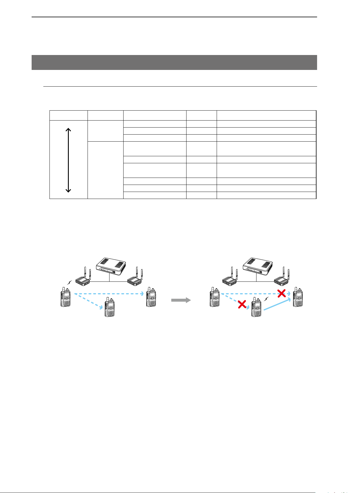
M Priority Call and its priority
The Priority Call function is set to “Disable” in the default setting.
The priority levels of the Call types are in the following order.
Priority level Priority Call type
High
Fixed
Selectable*
Low Group Call (Normal) Disable Includes the Area Call
Selectable in the Call Type Priority item in the [RoIP Server] screen in the [RoIP Server settings] menu. (p. 4-22)
*
• The priority is given to the first call between calls with the same priority level.
• The reply call follows the priority level of the talk side.
Change the target during communication with the Priority Call function enabled
Group Call
Telephone — For telephone communication
Emergency (High) Enable —
Emergency (Normal) Disable —
All Call (High) Enable
Individual Call (High) Enable Includes from an IP100FS
Group Call (High) Enable
All Call (Normal) Disable Includes the Area Call
Individual Call (Normal) Disable —
IP1000C
Wireless
access point
Making an Individual Call
during communication
Priority Call
Remarks
Includes the Area Call or calling from an
IP100FS
Includes the Area Call or calling from an
IP100FS
Group Call
IP100H
Individual Call
1-11
Page 17
BEFORE USING THE IP1000C
IP100H makes an All Call with the Area Call function
1
2. Feature description (continued)
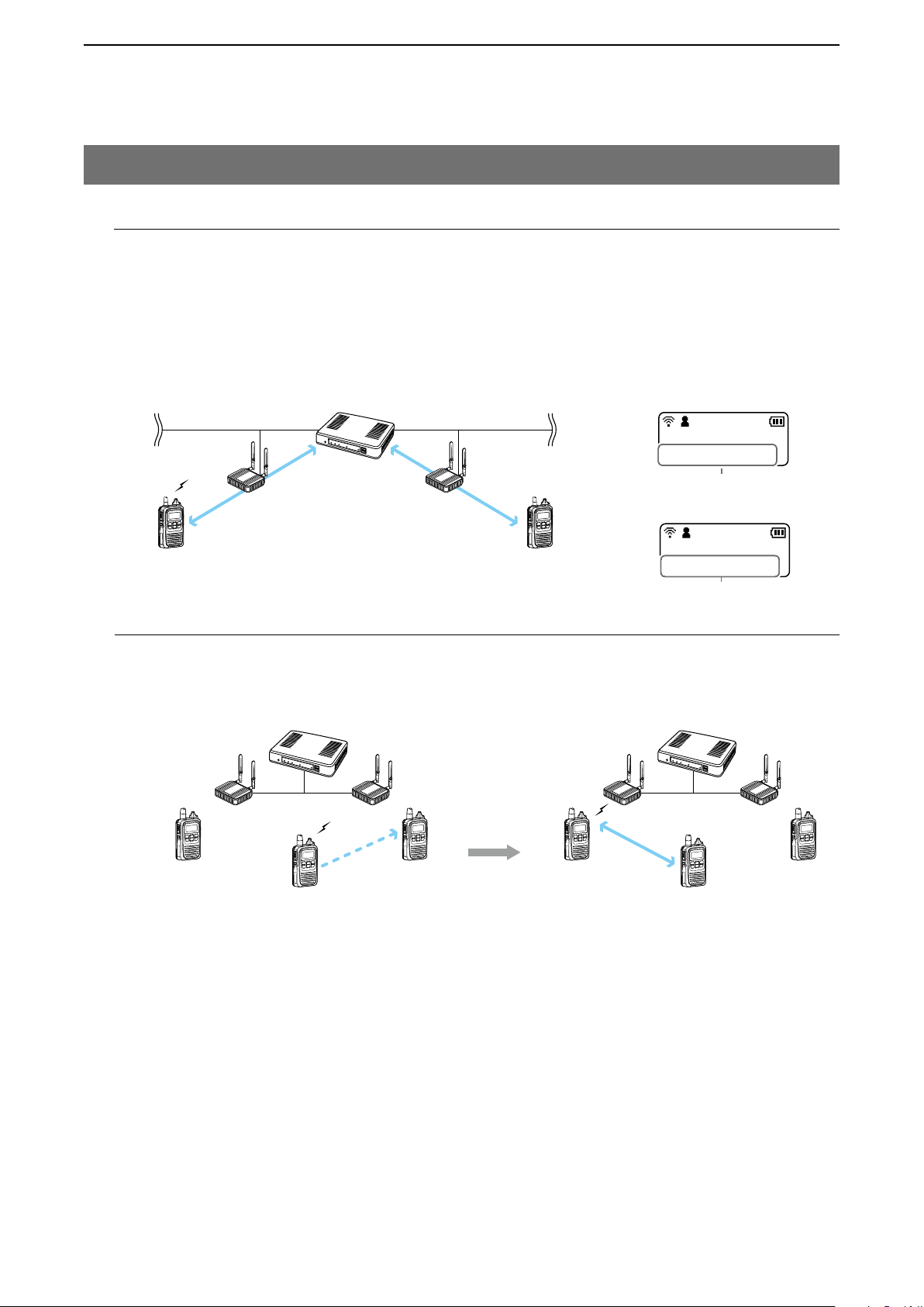
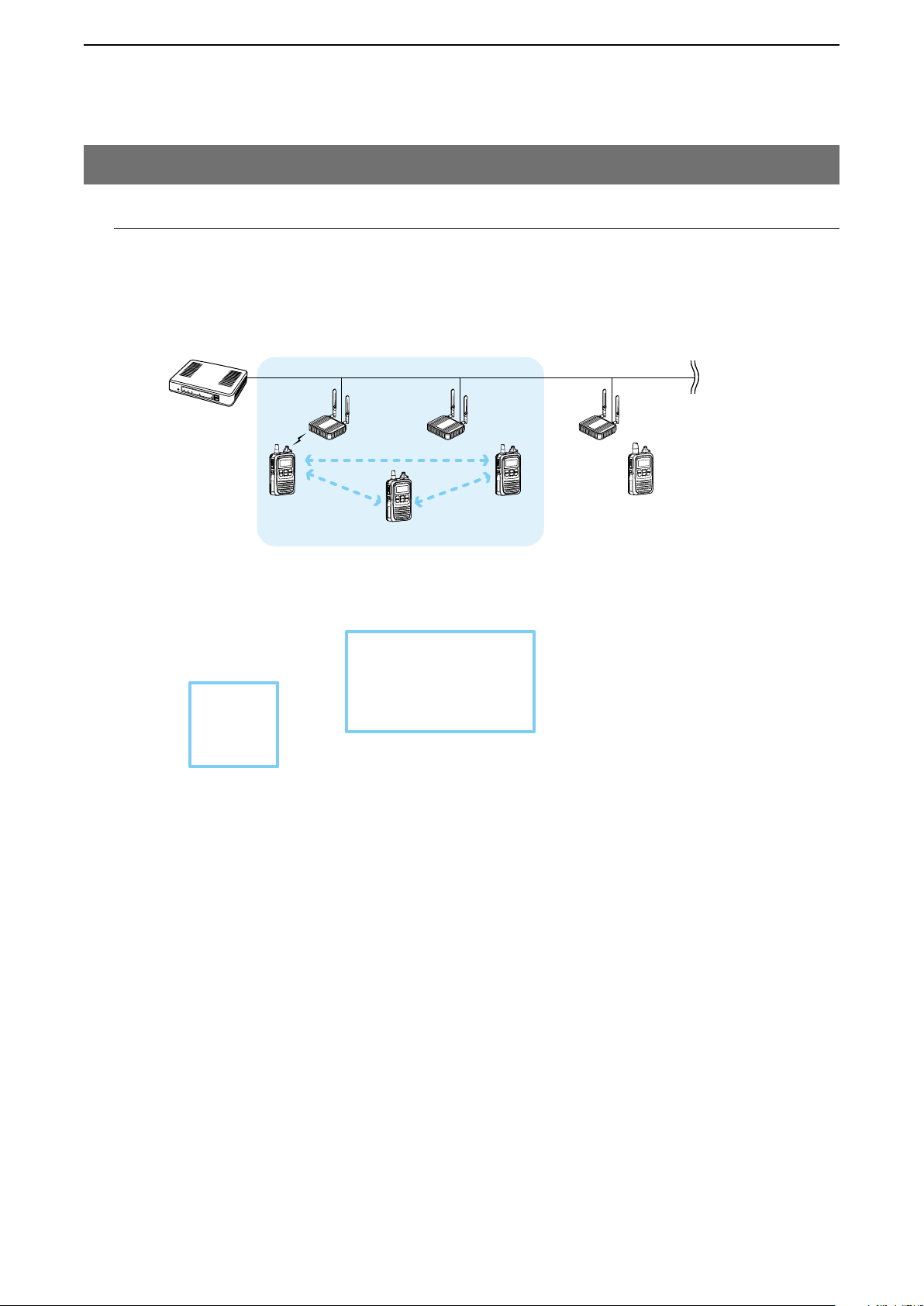
M Area Call
This function is used when operating by limiting to a certain area. (Default: Disable)
If you make an All Call or Group Call when Area Call in the IP100H is set to ON, the IP100H and IP100FS that are
in the same area with the IP100H connected to the wireless access point are called.
IP1000C
Sales Accounts Parts
All Call
The wireless access points that the
IP100H is included in with the Area Call
function, are set on the [Area Call] screen
in the [RoIP Server Settings] menu.
(Example: For Sales and For Accounts)
Wireless
access point
IP100H
IP100FS calls the All Call with the Area Call function
When the IP100FS uses the Area Call
function, can call IP100Hs that are in the
communication range of the access points
assigned to the Area Call.
Select the access point in the [Location], the
Call type (Individual, Group, All, Area or
Telephone) and names are displayed
To use Area Call, it is required to enable the [Area Call] for each IP100H in the [Transceiver Settings] screen, and
then register the area’s wireless access point (BSSID) in the [Area Entry List].
1-12
Page 18
BEFORE USING THE IP1000C
IP100H transmits a message
1
2. Feature description (continued)
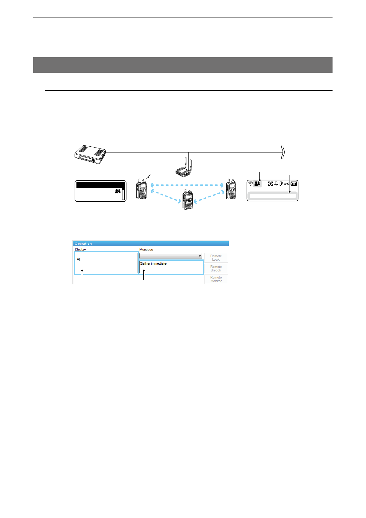
M Messages
Set this function to send a message with the IP100H and IP100FS. (Default: Disable)
The fixed messages of up to 32 characters to send can be set in the [Messages] screen of the [Common Setting]
Menu. Up to 10 messages can be registered.
Wireless
IP1000C
Message
All
Gather immedi
Message selection screen
(TX)
All Call
IP100H
access point
Blinks
Scrolls
1/25 12:57
All Gather imme
Received messege screen
(RX)
IP100FS transmits a message
The IP100FS can store up to 100 messages
in the each Site.
You can edit the stored messages.
Selected Call type Selected or edited message
• To use this function, requires to enable the [Message] item in the [Transceiver Settings] screen for each IP100H.
• The messages that are registered to the IP1000C are commonly used by the IP100Hs belonged to the setting
group.
1-13
Page 19
BEFORE USING THE IP1000C
1
2. Feature description (continued)
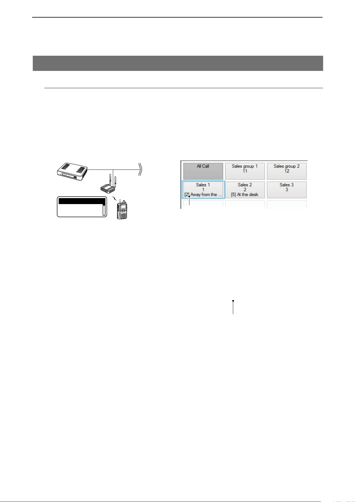
M About Status Settings
Set the Status to send the status information (Example: Away from the desk) from the IP100H. (Default: Disable)
• The status information of up to 32 characters can be programmed in the [Status] screen on the [Common Set
tings] menu. Up to 10 status can be programmed.
• The status information sent using the IP100H can be displayed in the One-Touch Button screen or in the [Trans
ceiver Management] screen on the [Transceiver Settings] menu.
-
-
IP100H sends the Status
IP1000C
Wireless
access point
Status
At lunch
Status selection screen
(TX)
IP1000C Transceiver Management screen
IP100H
IP100FS One-Touch button
Name, Destination ID, Status number
and Status information
Status
To use this function, requires to enable the [Status] item in the [Transceiver Settings] screen for each IP100H.
1-14
Page 20

SETTING UP THE IP1000C SYSTEM
1. Flow using IP100H ……………………………………………………………………………………………………………………… 2-2
M Prepare for connection and settings ……………………………………………………………………………………………… 2-2
M About the Setting procedures ……………………………………………………………………………………………………… 2-3
2. Transceiver settings ……………………………………………………………………………………………………………………… 2-4
M Registering the terminals …………………………………………………………………………………………………………… 2-5
M About confirming the registration and rebooting the IP100H …………………………………………………………………… 2-6
M About the IP100H settings ………………………………………………………………………………………………………… 2-7
M About the Group calls ……………………………………………………………………………………………………………… 2-8
M About the Talkgroup calls …………………………………………………………………………………………………………… 2-9
M About the ID list ……………………………………………………………………………………………………………………… 2-11
M About messages …………………………………………………………………………………………………………………… 2-12
M About the status settings …………………………………………………………………………………………………………… 2-13
M About commonly use the ID list and message in the group …………………………………………………………………… 2-14
3. Bridge connection and Caller settings ………………………………………………………………………………………………… 2-15
4. Additional controller link ………………………………………………………………………………………………………………… 2-19
5. Additional controller link with VE-PG3 ………………………………………………………………………………………………… 2-25
Section
2
2-1
Page 21
SETTING UP THE IP1000C SYSTEM
2
1. Flow using IP100H
M Prepare for connection and settings
This is an explanation of the flow from connecting with PC to accessing to the Setting screen.
1. Connect to a PC and turn ON the power See the CONNECTION GUIDE (Separated) for details
Connect a PC to the IP1000C’s [LAN] port, and insert the power cable into the [DC] jack.
Connect to a PC
IP1000C
Power cable
2. Access the setting screen See the CONNECTION GUIDE (Separated) for details
Open your web browser, then enter the IP address of the IP1000C into the address bar.
q
• The default IP address is “192.168.0.1.” (http://192.168.0.1/)
Push the [Enter] key.
w
• The Login Authentication screen will appear.
Enter “admin” (fixed username) and “admin” (default password) in their respective input fields on the Login Au
e
thentication screen, and then click <OK>.
-
2-2
Page 22

SETTING UP THE IP1000C SYSTEM
2
1. Flow using IP100H (continued)
M About the Setting procedures
This is a flow that the setting procedures of the IP100H using the IP1000C setting screen.
This manual explains after completing the wireless access point settings that the IP100Hs connect to.
1. Network Settings (pp. 4-11, 4-12)
Enter an IP address (default: 192.168.0.1) on the [IP Address] screen, and a DHCP server setting (default: Disable)
on the [DHCP Server] screen, according to your system environment.
2. Transceiver presettings
Register the IP100H or IP100FS to use into this IP1000C.
[Transceiver Registration] screen (pp. 2-5, 4-36)
Enter the Transceiver model, Name and Unit ID, Password and Setting group.
• The default password is “iptrx,” and you can change it for security.
• The common settings that are used by the group, are set in the [Common Settings] menu.
Setting by the CS-IP100H cloning software (p. 2-6)
After IP100Hs are registered to the IP1000C, set the wireless LAN setting, antenna setting (internal or external),
provisioning server setting (IP1000C) to all the IP100Hs.
• The CS-IP100H is a freeware that can be downloaded from the Icom website.
• First, read the instructions of the CS-IP100H that can be downloaded from the Icom website, and follow its
procedure to connect the cloning cable between the IP100H and a PC.
3. Common Settings (pp. 2-11 to 2-14)
Set common settings of each group that the IP100Hs or IP100FSs belong to and are registered on the [Transceiver
Registration] screen.
[ID List] screen
Register the unit IDs that are registered on the [Transceiver Registration] screen or the group IDs that are regis
tered on the [Destination Settings] screen.
• When an IP1000C’s bridge connection is made with a VE-PG3, you can register the telephone number of the
IP phone.
[Message] screen
Enter messages that the IP100H will send.
Up to 32 characters can be programmed. (Up to 10 messages.)
-
[Status] screen
Enter Statuses that the IP100H will send.
Up to 32 characters can be programmed. (Up to 10 statuses.)
[Common Settings] screen
Specify the ID list and message list of the group that the IP100H belongs.
About updating setup
If the IP1000C’s setup has been changed, be sure to reboot the IP100H to read its setting.
2-3
Page 23
SETTING UP THE IP1000C SYSTEM
2
1. Flow using IP100H
M About the Setting procedures (continued)
4. Transceiver Settings
(pp. 4-34 to 4-37)
Set or assign the functions to all the IP100Hs that are registered on the [Transceiver Registration] screen.
Use ID list
Priority Call
Message
5. Destination Settings
Communication Method (Simplex/Full-duplex)
Area Call
Status
(p. 2-8)
The registered IP100Hs or IP100FS on the [Transceiver Registration] screen, are assigned to a group, assigned a
group ID and the communication type is set on the [Destination Settings] screen.
6. Mic gain, Notification beep or Talkback setting
(pp. 4-53 to 4-56, 4-85 to 4-92)
Depending on your system requirement, set the mic gain or assign the VOX function* on the [Transceiver Set-
tings] screen, set common settings, such as the various notice tones, talkback settings on the [Common Settings]
screen.
* The VOX function requires to connect an optional headset and connection cable.
Headset HS-94, HS-95, or HS-97 and Connection cable OPC-2006LS.
Or Headset HS-102 and Connection cable OPC-2359.
2. Transceiver settings
Each terminal requires that you set the unit ID and so on.
The following illustration is an example of setting requirements to register an IP100H to an IP1000C.
Wireless
IP1000C
192.168.0.1 192.168.0.50
IP100H
Sales1
Sales2
0001
0002
Sales group1
0101
Meeting
access point
Sales3
0003
Full-duplex
operation
Sales4
0004
IP100FS
(Remote communicator)
Setting Group1
• Connect a wireless access point to the IP1000C network.
• Up to 100 of the total IP100H and IP100FS can register to the IP1000C.
(Depending on the IP1000C versions, up to 20 of total IP100H and IP100FS can be registered.)
• This manual explains that IP addresses of the IP100H or a PC using the IP100FS are automatically assigned by
the DHCP server on the network
• When assigning static IP addresses to the terminals, make sure that the addresses of the devices on the network
don’t overlap or conflict.
2-4
Page 24
SETTING UP THE IP1000C SYSTEM
2
2. Transceiver settings (continued)
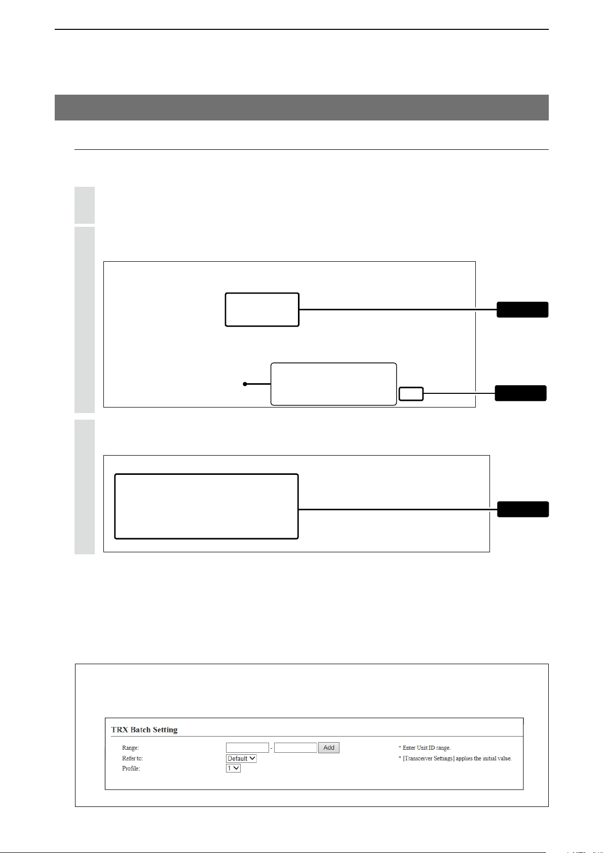
M Registering the terminals
Set the Unit ID (Individual number) to register each IP100H or IP100FS.
Click [Transceiver Settings], then [Transceiver Registration].
1
• The [Transceiver Registration] screen is displayed.
Enter the “Transceiver Model,” “Name” and “Unit ID” items in the “Transceiver Settings” field, and then click
2
<Add>.
q Enter
This number is specified in the
Common Settings field on the
[Common Settings] screen.
After registration is finished, confirm the registered contents the terminal in the “Transceiver Setting Entry
3
List” field. (See pages 2-7, 2-8 and 2-10.)
w Click
Confirm
About the TRX Batch Setting
You can register a consecutive Destination ID collectively. You can also copy the Destination ID settings to other Desti-
nation ID settings.
2-5
Page 25
SETTING UP THE IP1000C SYSTEM
Blinks Scrools
Talkgroup icon
2
2. Transceiver settings (continued)
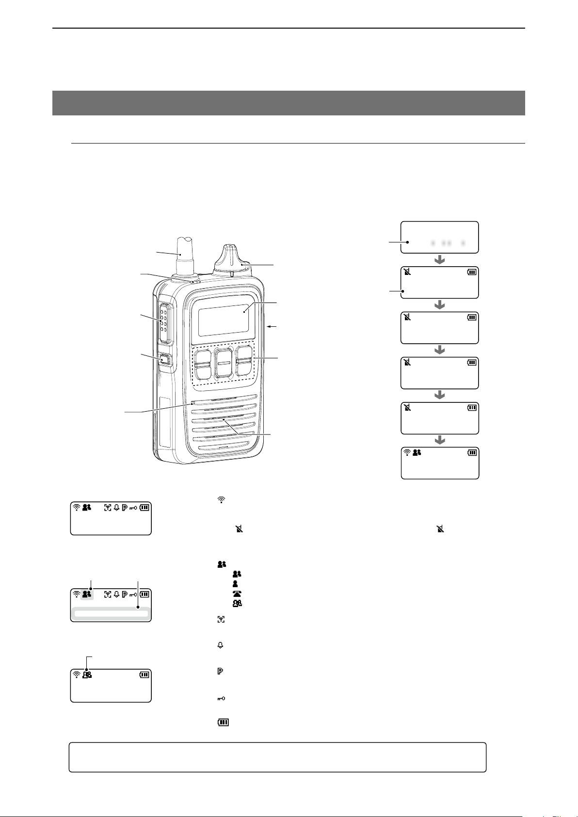
M About confirming the registration and rebooting the IP100H
After the registration of the IP100H to the IP1000C is completed, program the IP100H using the CS-IP100H clon-
ing software and a PC.
After that, reboot the IP100H and it will automatically read the contents of the IP1000C’s setting.
• The CS-IP100H is a freeware that can be downloaded from the Icom website.
• If the IP100H will not display the standby screen, check the settings of the IP1000C and the wireless access
point.
External antenna
[TX/RX] LED
[PTT] switch
[Option] key
Version
information
[PWR/VOL]
knob
Unit ID
Function display
Jack cover
Function keys
IP100H
Ver. . /
Booting...
0001
Connecting...
0001
Setting up...
0001
Internal
microphone
About the display icons
10/3 12:57
All
Standby screen
10/3 12:57
All Gather imme
When a message is received
10/3 12:57
Talkgroup
When Talkgroup call is selected
Successful
Internal speaker
0001
10/3 12:57
All
(Standby screen)
• Signal strength indicator
Displays the signal strength in three levels when your communica-
tion terminal is in a service area.
“ ” blinks when you are in out of the service area, and “ ” ap-
pears if your communication terminal is not registered, or not connected to the IP1000C.
• Call mode icon
: Appears when All or Group call is selected.
: Appears when Individual call is selected.
: Appears when Telephone call is selected.
: Appears when Talkgroup call is selected.
• Area call function icon
Appears when the Area call function is ON.
• Beep function icon
Appears when the Beep function is ON.
• P-Bell function icon
Appears when the P-Bell function is ON.
• Key lock function icon
Appears when the Key lock function is ON.
• Battery indicator
Displays the attached battery pack’s remaining battery charges.
About updating setup
If the IP1000C’s setup has been changed, be sure to reboot the IP100H to read its setting.
2-6
Page 26
SETTING UP THE IP1000C SYSTEM
2
2. Transceiver settings (continued)
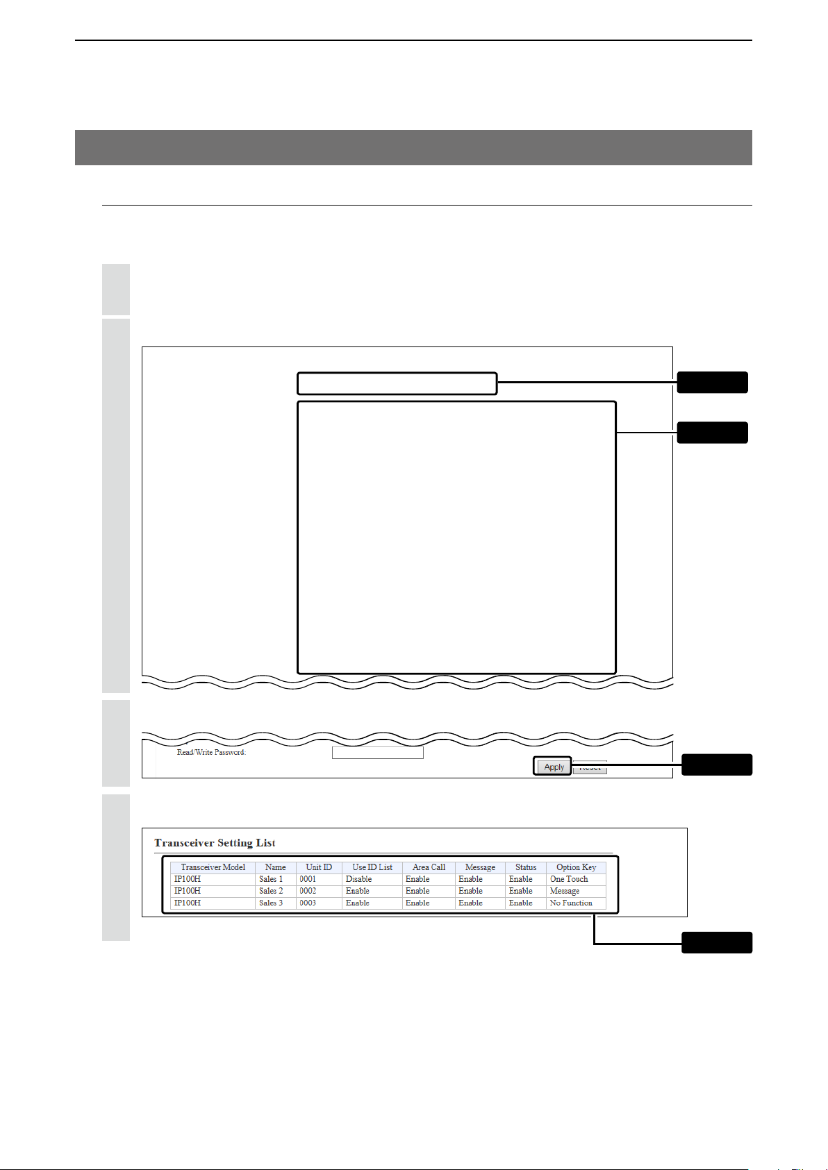
M About the IP100H settings
Set and assign functions to each registered IP100H.
After the settings have been changed, the IP100H needs to be rebooted.
Click [Transceiver Settings], then [Transceiver Settings].
1
• The [Transceiver Settings] screen is displayed.
Select the “Unit ID” item to be set, then select and assign functions, depending on your requirements.
2
q Select
w Enter
Click <Apply>.
3
After registration is finished, confirm the registered contents in the “Transceiver Setting List” field.
4
Click
Confirm
2-7
Page 27
SETTING UP THE IP1000C SYSTEM
2
2. Transceiver settings (continued)
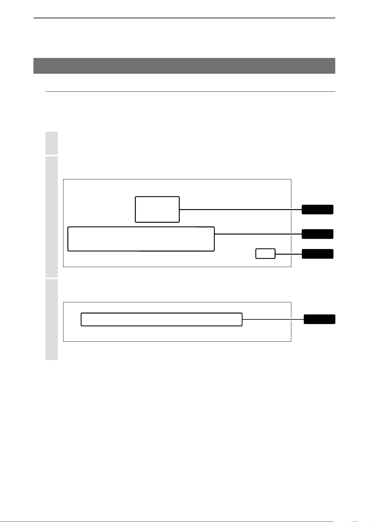
M About the Group calls
This topic describes registering IP100Hs or IP100FSs to a group, and they communicate with the full-duplex op-
eration between three or more members as meeting.
After the settings have been changed, the IP100H needs to be rebooted.
Click [Destination Settings].
1
• The [Destination Settings] screen is displayed.
Enter the group name, Call type and a 4 digit group ID in the “Destination Setting” field, then select the ter-
2
minals in the list that belong to the group. Click <Apply>.
After registration is finished, confirm the registered contents in the “List of Destination Setting Entries (Group
3
Call)” field.
q Enter
w Select
e Click
Confirm
2-8
Page 28
SETTING UP THE IP1000C SYSTEM
2
2. Transceiver settings (continued)
M About the Talkgroup calls
This topic describes registering IP100Hs or IP100FSs to a Talkgroup, and they communicate with the full-duplex
operation between three or more members as meeting.
The Talkgroup Call function allows user to select the group that belong to it from previously registered groups in the
IP1000C.
The [FUNC] key or [ID List] key can be assigned for selecting the Talkgroup.
After the settings have been changed, the IP100H needs to be rebooted.
Click [Destination Settings].
1
• The [Destination Settings] screen is displayed.
Enter the Talkgroup name, Call type and a 4 digit group ID in the “Destination Setting” field. Click <Apply>.
2
Select “Multiplex Talkgroup” to call between the
talkgroups that are linked previously. (p.4-99)
After registration is finished, confirm the registered contents in the “List of Destination Setting Entries (Talk
3
Group Call)” field.
q Enter
w Click
-
Confirm
2-9
Page 29
SETTING UP THE IP1000C SYSTEM
Talkgroup is selected
2
2. Transceiver settings (continued)
M About the Talkgroup calls (continued)
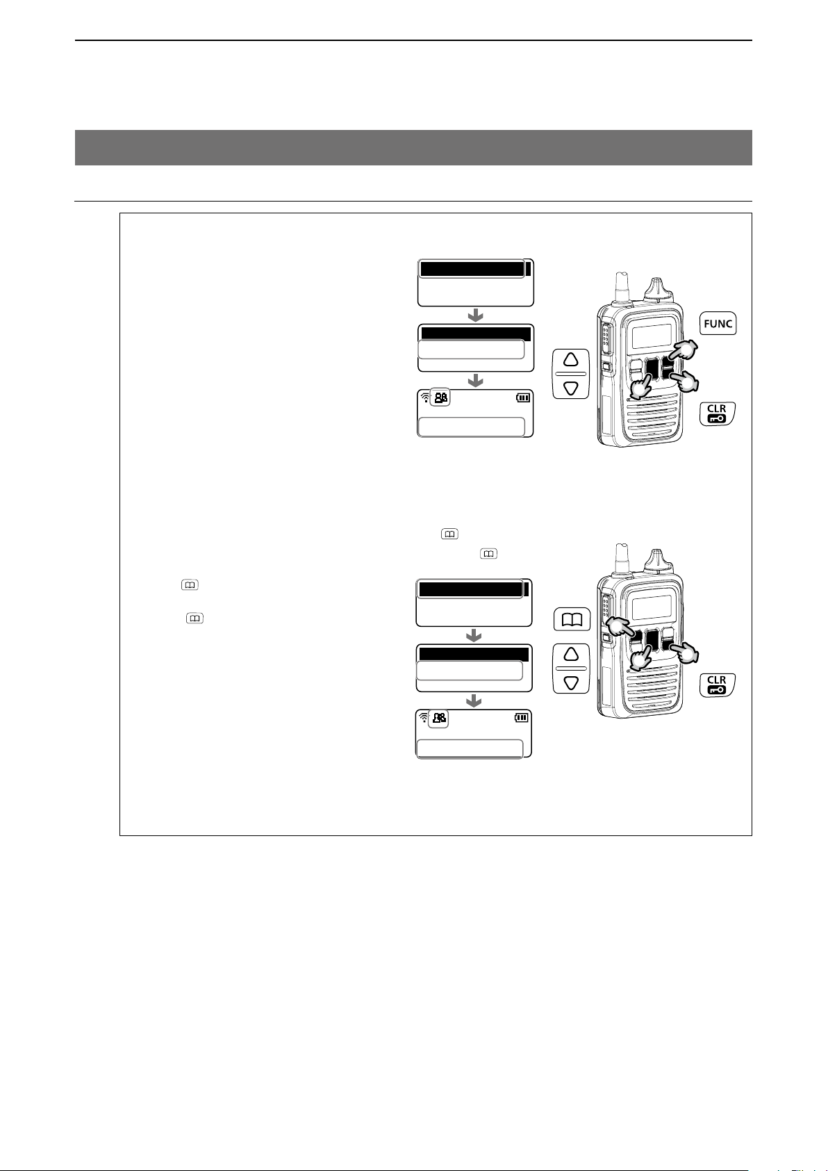
Selecting the Talkgroup call using the IP100H (with [FUNC] key)
Available only when the Talkgroup Call function is assigned to [FUNC] key.
q Push [FUNC] several times to select the
Talkgroup.
• Push [FUNC] to select the assigned functions such as Message, Status, Area Call,
and so on.
w Push [r ] or [s] to select the Talkgroup
number.
e Push [CLR/LOCK].
• You can talk with the IP100Hs or
IP100FSs that select the same group
number. (Example 0202)
• When you select the Talkgroup Call, you
are excluded from original group. (p. 2-8)
• When “OFF” is selected in step w, the
Talkgroup is released.
Talkgroup
OFF
Talkgroup
0202
Talkgroup 2
10/3 12:57
Talkgroup 2
Selecting the Talkgroup call using the IP100H (with [ ] key)
Available only when the Talkgroup Call function is assigned to
q Push [ ] several times to select the
Group (or Talkgroup.)
• Push [
tions such as All, Individual, and so on.
w Push [r ] or [s] to select the Talkgroup
number.
e Push [CLR/LOCK].
• You can talk with the IP100Hs or
IP100FSs that select the same group
number. (Example 0202)
• When you select the Talkgroup Call, you
are excluded from original group. (p. 2-8)
• When “Group” is selected in step w, the
Talkgroup is released.
] to select the assigned func-
Group
0101
Group 1
Talkgroup
0202
Talkgroup 2
10/3 12:57
Talkgroup 2
Talkgroup is selected
[ ] key.
q
w
q
w
e
e
2-10
Page 30
SETTING UP THE IP1000C SYSTEM
2
2. Transceiver settings (continued)
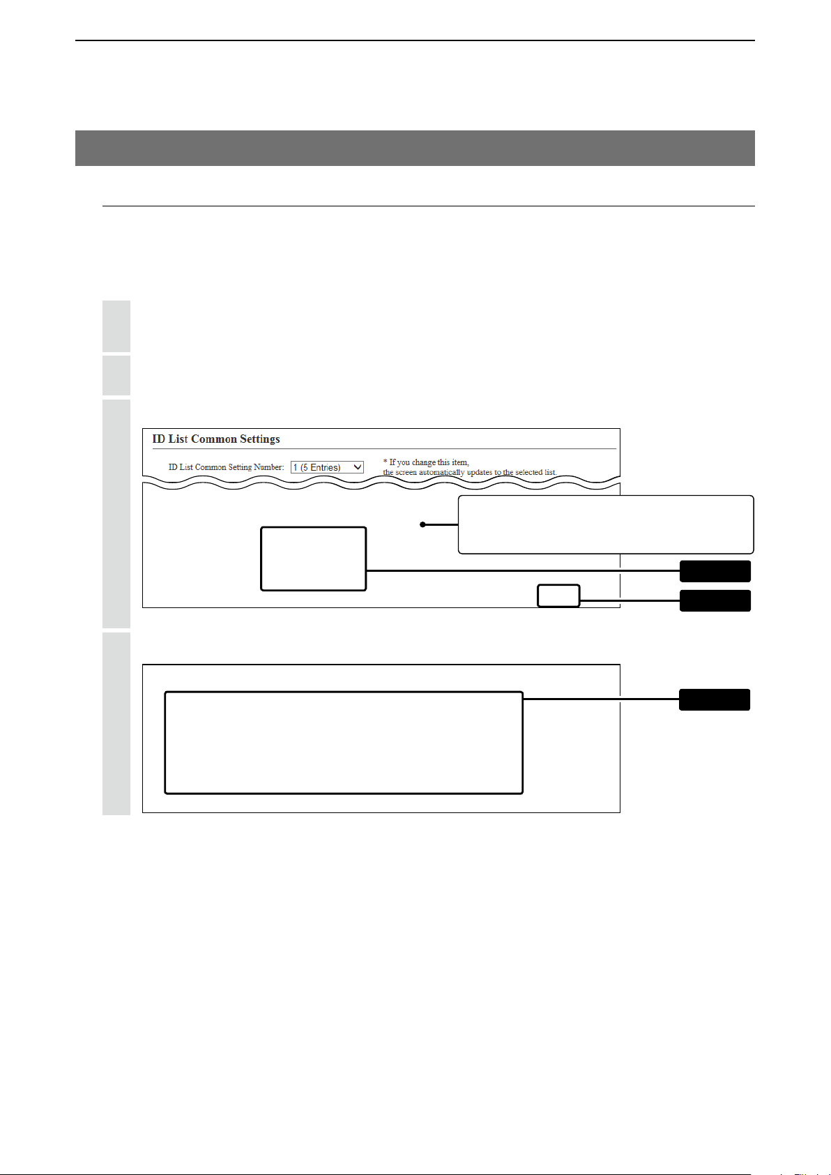
M About the ID list
Enter Names, Call types and so on in an ID list that the IP100H will use.
After registration is finished, the IP100H needs to be rebooted.
When using the ID list, set the “Use ID List” to “Enable.” (p.4-40)
Click [Common Settings], then [ID list].
1
• The [ID List] screen is displayed.
Select the ID list group in the “ID List Common Settings” field.
2
• The ID list group number (example: 1) is used in the “ID List” item on the [Common Settings] screen.
Enter the name, Call type and a 4 digit destination ID in the “ID List” field, then click <Apply>.
3
Select "Select From List" when selecting the
registered Destination ID in the [Transceiver
Registration] screen or [Destination Settings] screen.
After registration is finished, confirm the registered contents in the “ID List Entries” field.
4
q Enter
w Click
Confirm
2-11
Page 31
SETTING UP THE IP1000C SYSTEM
2
2. Transceiver settings (continued)
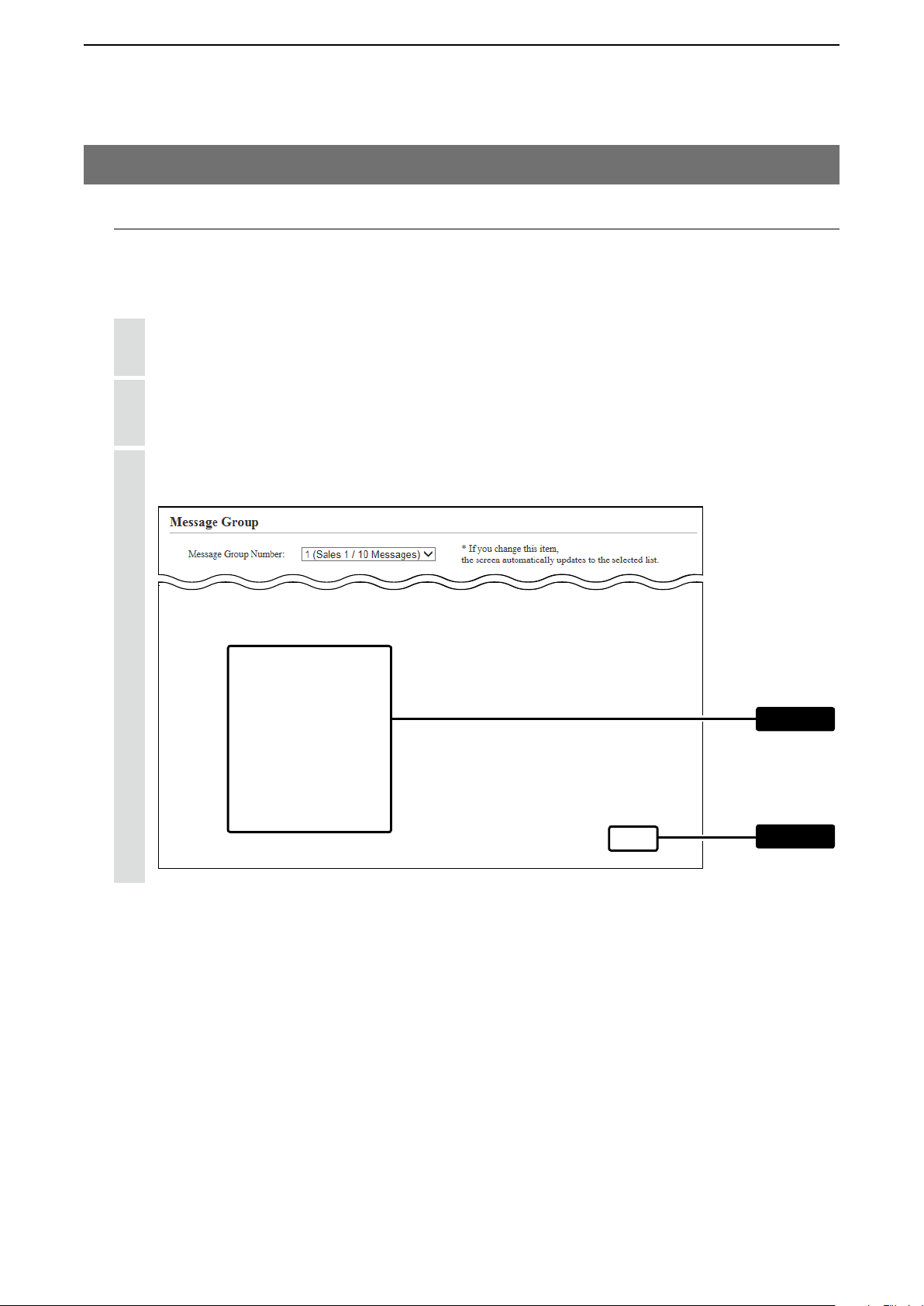
M About messages
Enter messages that the IP100H will transmit.
After registration is finished, the IP100H needs to be rebooted.
When using the Message, set the “Message” to “Enable.” (p.4-45)
Click [Common Settings], then [Messages].
1
• The [Messages] screen is displayed.
Select the message group number in the “Message Group” field.
2
• The message group number (example: 1) is used in the “Message List” item on the [Common Settings]
screen.
Enter a message of up to 32 characters in the “Messages” field. Then click <Apply>.
3
• Up to 10 messages can be registered in each group.
q Enter
w Click
2-12
Page 32

SETTING UP THE IP1000C SYSTEM
2
2. Transceiver settings (continued)
M About the status settings
Enter the status that the IP100H will transmit.
After registration is finished, the IP100H needs to be rebooted.
When using the Status, set the “Status” to “Enable.” (p.4-46)
Click [Common Settings], then [Status].
1
• The [Status] screen is displayed.
Enter a status of up to 32 characters in the “Status Setting” field. Then click <Apply>.
2
• Up to 10 statuses can be entered.
• The items that are unchecked are not displayed on the IP100H.
q Enter
w Click
2-13
Page 33

SETTING UP THE IP1000C SYSTEM
2
2. Transceiver settings (continued)
M About commonly use the ID list and message in the group
Specify the ID and message lists of the group that the IP100H belongs to.
After registration is finished, the IP100H needs to be rebooted.
Click [Common Settings], then [Profile].
1
• The [Profile] screen is displayed.
Select the profile number in the “Profile” field.
2
• The profile number setting (example: 1) is specified in the “Profile” item on the [Transceiver Registration]
screen in each IP100H.
Select the “ID List” and “Message List” in the “Profile” field.
3
Select the specified ID list group on the [ID List]
screen (p. 2-11) or message group on the [Message]
screen (p. 2-12).
Click <Apply>.
4
5
After registration is finished, confirm the registered contents in the “Profile List” field.
Enter
Click
Confirm
2-14
Page 34

SETTING UP THE IP1000C SYSTEM
Bridge connection
2
3. Bridge connection and Caller settings
When making a bridge connection with a VE-PG3*, the IP1000C system can communicate with the transceivers.
* A VE-PG3 with a firmware version 1.13 or less cannot communicate with the IP1000C system.
Before connecting the VE-PG3, check the firmware version on the VE-PG3’s setting screen.
Extension number 2001
VE-PG3
IP1000C
192.168.0.1
Wireless
Sales2
0002
access point
IP100H
Sales1
0001
Seles group1
0011
About the IP1000C settings
1. Enter the IP address of the VE-PG3 in the [Telephone Gateway Interconnection] field. (Example: 192.168.0.2)
[RoIP Server Settings] (menu) > [Telephone Gateway Interconnection] (screen) > [Telephone Gateway Intercon
nection] (field)
(RoIP Gateway)
192.168.0.2
IP phone
Extension number 500
-
This number is the same as the
“Telephone Gateway Interconnec-
tion Number” item in the [Destina-
tion Setting] field.
2. After setting the “Call Type” item to “Telephone,” select the “Telephone Gateway Interconnection Number” item
and then enter a telephone number in the “Destination Phone Number” item.
[Destination Settings] (menu) > [Destination Settings] (screen) > [Destination Setting] (field)
• Select the bridge number as same as the number that is selected the [Telephone Gateway Interconnection]
field. (Example: 1)
• Enter the VE-PG3’s extension number. (Example: 500)
This number is the same as the “No.”
item in the [Telephone Gateway Inter-
connection Number] field.
3. After setting the “Call Type” item to “Telephone,” enter the “Destination Phone Number” item.
[Common Settings] (menu) > [ID List] (screen) > [ID List] (field)
• Enter the VE-PG3’s extension number. (Example: 500)
(Continued to next page)
2-15
Page 35

SETTING UP THE IP1000C SYSTEM
Bridge connection
Push
2
3. Bridge connection and Caller settings (continued)
Extension number 2001
VE-PG3
IP1000C
192.168.0.1
Wireless
Sales2
0002
access point
IP100H
Sales1
0001
Seles group1
0011
About the IP1000C settings (Continued)
4. Confirm the [Clear Down during Telephone Call] item in the [Transceiver Settings] field is set to “Enable.”
[Transceiver Settings] (menu) > [Transceiver Settings] (screen) > [Transceiver Settings] (field)
(RoIP Gateway)
192.168.0.2
IP phone
Extension number 500
When “Clear Down” is selected in the [Op-
tion Key] item, the [Clear Down during
Telephone Call] item is not displayed.
Before the target telephone is picked up, or during
phone call, pushing [Option] terminates the phone
call.
• The IP100H can terminate the phone call, when a
telephone calls the IP100H individually, or when the
IP100H calls a telephone.
(Continued to next page)
2-16
Page 36

SETTING UP THE IP1000C SYSTEM
Bridge connection
2
3. Bridge connection and Caller settings (continued)
Extension number 2001
VE-PG3
IP1000C
192.168.0.1
Wireless
Sales2
0002
access point
IP100H
Sales1
0001
Seles group1
0011
About the VE-PG3 settings (Converter mode)
1. Enter the IP address of the IP1000C in the [Bridge Connection] field. (Example: 192.168.0.1)
Select the Voice Cording. (Example: G.711u Signaling)
[Port Settings] (menu) > [Bridge] (screen) (Example: Bridge1) > [Bridge Connection] (field)
• Make sure the using port number for connection don’t duplicate with another connection.
2. Select the call type and enter the destination ID in the [Bridge Communication] field.
Call type (Example: Group), Destination ID (Example: 11)
3. For full-duplex telephone operation, set the “Priority Receive” item in the [Bridge Control] field to “Disable.”
4. Click <Apply> at bottom of the screen. Then click <Connect> in the [Bridge Connection] field.
• The “Connection Status” item changes form “Not Connected” to “During Transmit.”
(RoIP Gateway)
192.168.0.2
IP phone
Extension number 500
After settings in this screen are
completed, click <Apply>.
Then click <Connect>.
“Default Callee ID” item is set
to “Enable,” set the Destination
settings below.
Set the PTT control or Call
Control types according to your
requirements.
(Continued to next page)
2-17
Page 37

SETTING UP THE IP1000C SYSTEM
2
3. Bridge connection and Caller settings (continued)
Extension number 2001
VE-PG3
(RoIP Gateway)
192.168.0.2
IP phone
Extension number 500
IP1000C
192.168.0.1
IP100H
Sales1
0001
Bridge connection
Sales2
Seles group1
0011
0002
Wireless
access point
About the VE-PG3 settings (Converter mode)—continued
5. Enter the extension number of the [Bridge 1] port in the [Extension] field. (Example: 2001)
[Extension Connect] (menu) > [Extension Connect] (screen) > [Extension] (field)
The “Port Type” item must be
set to the same port as the one
set in step 1.
6. Enter the extension number of the IP phone in the [Extension] field. (Example: 500)
[Extension Connect] (menu) > [Extension Connect] (screen) > [Extension] (field)
Enter the IP phone’s MAC ad-
dress
When the IP phone calls the number “2001,” all the IP100Hs of sales group “0011” will be called.
• The caller number on the IP100H’s display will be the extension number of the IP phone. (Example: 500)
When the IP phone calls the number “011” + “0001,” only the IP100H of Sales 1 “0001” will be called.
• The numbers “011” and “0001” are individual numbers for the [Bridge 1] port and Sales 1.
• The caller number on the IP100H’s display will be the extension number of the IP phone. (Example: 500)
See the VE-PG3 instruction manual for the setting details.
When the IP100H (example: Sales 2 “0002”) calls the IP phone:
Display the IP phone’s Destination phone number on the IP100H’s screen.
q
• The Destination phone number of the IP phone must be programmed in the IP100H’s ID list.
Hold down [PTT] for more than 1 second.
w
• The caller number on the IP phone’s display will be the individual number of Sales 2. (Example: “011” + “0002”)
See the IP100H instruction manual for the operating details.
2-18
Page 38

SETTING UP THE IP1000C SYSTEM
IP100H makes a Group Call with the Additional Controller Link
2
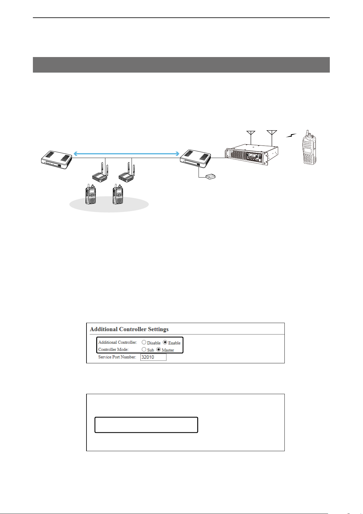
4. Additional controller link
The Additional Controller Link function allows you to communicate another sites.
*Up to 10 sub IP1000Cs can be connected to a master IP1000C.
*Use a VPN router, such as Icom’s SR-VPN1, between sites if necessary.
IP1000C
192.168.0.1
Office1 (Master)
Wireless
access point
Additional Controller Link
192.168.0.2
Office2 (Sub)
IP100H
Sales21
0021
Sales group2
0201
Sales22
0022
Sales31
0031
Sales group3
0301
Sales1
0001
Sales32
0032
Sales group1
0101
192.168.0.3
Office3 (Sub)
About the Office1 setting (Master)
1. Select “Enable” in the [Additional Controller] item, and “Master” in the [Controller Mode] item.
Then click <reboot> to reboot the IP1000C.
[RoIP Settings] (menu) > [RoIP Settings] (screen) > [Additional Controller Settings] (field)
Sales2
0002
2. Enter a name and a destination IP address.
[RoIP Server Settings] (menu) > [Additional Controller Link] (screen) > [Additional Controller Settings] (field)
2-19
Page 39

SETTING UP THE IP1000C SYSTEM
IP100H makes a Group Call with the Additional Controller Link
2
4. Additional controller link (continued)
IP1000C
192.168.0.1
Office1 (Master)
Wireless
access point
Additional Controller Link
192.168.0.2
Office2 (Sub)
IP100H
Sales21
0021
Sales group2
0201
Sales22
0022
Sales31
0031
Sales group3
0301
Sales1
0001
Sales32
0032
Sales group1
0101
192.168.0.3
Office3 (Sub)
Sales2
0002
About the Office1 setting (Master) – continued
3. Select “Group” in the [Call Type] item, enter a destination ID and select a group priority. Select controllers in the
[Additional Controller] item. (Refer to an example below.)
[Destination Settings] (menu) > [Destination Settings] (screen) > [Destination Settings] (field)
The number of transceivers in a site, and any ad-
ditional controllers that are set, are displayed.
Select only Office2 when you do not make a
call from Office3 to Office2 using the group
number “0201.”
2-20
Page 40

SETTING UP THE IP1000C SYSTEM
IP100H makes a Group Call with the Additional Controller Link
2
4. Additional controller link (continued)
IP1000C
192.168.0.1
Office1 (Master)
Wireless
access point
Additional Controller Link
192.168.0.2
Office2 (Sub)
IP100H
Sales21
0021
Sales group2
0201
Sales22
0022
Sales31
0031
Sales group3
0301
Sales1
0001
Sales32
0032
Sales group1
0101
192.168.0.3
Office3 (Sub)
About the Office2 setting (Sub) (Example: Calling Sales group 2 (0201))
1. Select “Enable” in the [Additional Controller] item, and “Sub” in the [Controller Mode] item.
Then click <reboot> to reboot the IP1000C.
[RoIP Settings] (menu) > [RoIP Settings] (screen) > [Additional Controller Settings] (field)
Sales2
0002
2 . Enter a name and a destination IP address. (Example: Office1 (Master)).
[RoIP Server Settings] (menu) > [Additional Controller Link] (screen) > [Additional Controller Settings] (field)
2-21
Page 41

SETTING UP THE IP1000C SYSTEM
IP100H makes a Group Call with the Additional Controller Link
2
4. Additional controller link (continued)
IP1000C
192.168.0.1
Office1 (Master)
Wireless
access point
Additional Controller Link
192.168.0.2
Office2 (Sub)
IP100H
Sales21
0021
Sales group2
0201
Sales22
0022
Sales31
0031
Sales group3
0301
Sales1
0001
Sales32
0032
Sales group1
0101
192.168.0.3
Office3 (Sub)
Sales2
0002
About the Office2 setting (Sub) – continued
3. Select “Group” in the [Call Type] item, enter a destination ID and select a group priority. Select controllers in the
[Additional Controller] item. (Refer to an example below.)
[Destination Settings] (menu) > [Destination Settings] (screen) > [Destination Settings] (field)
The number of transceivers in a site, and any
additional controllers that are set, are displayed.
Select Master in the [Addi-
tional Controller] item for other
IP1000Cs (Sub).
2-22
Page 42

SETTING UP THE IP1000C SYSTEM
IP100H makes a Group Call with the Additional Controller Link
2
4. Additional controller link (continued)
IP1000C
192.168.0.1
Office1 (Master)
Wireless
access point
Additional Controller Link
192.168.0.2
Office2 (Sub)
IP100H
Sales21
0021
Sales group2
0201
Sales22
0022
Sales31
0031
Sales group3
0301
Sales1
0001
Sales32
0032
Sales group1
0101
192.168.0.3
Office3 (Sub)
About the Office3 setting (Sub)
1. Select “Enable” in the [Additional Controller] item, and “Sub” in the [Controller Mode] item.
Then click <reboot> to reboot the IP1000C.
[RoIP Settings] (menu) > [RoIP Settings] (screen) > [Additional Controller Settings] (field)
Sales2
0002
2 . Enter a name and a destination IP address. (Example: Office1 (Master))
[RoIP Server Settings] (menu) > [Additional Controller Link] (screen) > [Additional Controller Settings] (field)
2-23
Page 43

SETTING UP THE IP1000C SYSTEM
IP100H makes a Group Call with the Additional Controller Link
2
4. Additional controller link (continued)
IP1000C
192.168.0.1
Office1 (Master)
Wireless
access point
Additional Controller Link
192.168.0.2
Office2 (Sub)
IP100H
Sales21
0021
Sales group2
0201
Sales22
0022
Sales31
0031
Sales group3
0301
Sales1
0001
Sales32
0032
Sales group1
0101
192.168.0.3
Office3 (Sub)
Sales2
0002
About the Office3 setting (Sub) – continued
3. Select “Group” in the [Call Type] item and enter a destination ID. Select controllers in the [Additional Controller]
item. (Refer to an example below.)
[Destination Settings] (menu) > [
Destination Settings
] (screen) > [
Destination Settings
] (field)
The number of transceivers in a site, and any
additional controllers that are set, are displayed.
Select Master in the [Addi-
tional Controller] item for other
IP1000C (Sub).
2-24
Page 44
SETTING UP THE IP1000C SYSTEM
2
5. Additional controller link with VE-PG3
The Additional Controller Link function allows you to communicate with the digital transceiver in the IDAS system.
IP100H makes a Group Call with the Additional Controller Link (VE-PG3)
192.168.0.2
(Area A)
[D-TRX1]
[USB]
CT-24
Port number (Controller 1): 21500
Port number (D-TRX1): 21502
P
0
P
1
P
2
P
3
P
4
192.168.0.11
Repeater A
IP1000C
192.168.0.3
(Area B)
IP100H
Sales31
0031
Additional Controller Link
Controller connection
Sales group3
0301
Sales32
0032
VE-PG3
(RoIP Gateway)
Transceiver
About the IP1000C settings
1. Select “Enable” in the [Additional Controller] item, and “Master” in the [Controller Mode] item.
Then click <reboot> to reboot the IP1000C.
[RoIP Settings] (menu) > [RoIP Settings] (screen) > [Additional Controller Settings] (field)
• When several IP1000Cs are linked and use All call or Group call between the controllers, the IP1000C whose
Controller mode is set to “Sub” cannot link to the bridge mode’s VE-PG3 to additional controller. In that case,
the VE-PG3 must be linked to the IP1000C whose Controller mode is set to “Master.”
2. Enter a name and a destination IP address. (Example: VE-PG3 (Area A))
[RoIP Server Settings] (menu) > [Additional Controller Link] (screen) > [Additional Controller Settings] (field)
2-25
Page 45

SETTING UP THE IP1000C SYSTEM
2
5. Additional controller link with VE-PG3 (continued)
IP100H makes a Group Call with the Additional Controller Link (VE-PG3)
192.168.0.2
(Area A)
[USB]
Port number (Controller 1): 21500
Port number (D-TRX1): 21502
IP1000C
192.168.0.3
(Area B)
IP100H
Sales31
0031
Additional Controller Link
Controller connection
Sales group3
0301
Sales32
0032
VE-PG3
(RoIP Gateway)
CT-24
[D-TRX1]
P
0
P
1
P
2
P
3
P
4
192.168.0.11
Repeater A
Transceiver
About the IP1000C settings (Continued)
3. Select “Group” in the [Call Type] item and enter a destination ID. Select controllers in the [Additional Controller]
item. (Refer to an example below.)
[Destination Settings] (menu) > [Destination Settings] (screen) > [Destination Settings] (field)
2-26
Page 46

SETTING UP THE IP1000C SYSTEM
2
5. Additional controller link with VE-PG3 (continued)
IP100H makes a Group Call with the Additional Controller Link (VE-PG3)
192.168.0.2
(Area A)
[USB]
CT-24
Port number (Controller 1): 21500
Port number (D-TRX1): 21502
IP1000C
192.168.0.3
(Area B)
IP100H
Sales31
0031
Additional Controller Link
Controller connection
Sales group3
0301
Sales32
0032
VE-PG3
(RoIP Gateway)
[D-TRX1]
P
0
P
1
P
2
P
3
P
4
192.168.0.11
Repeater A
Transceiver
About the VE-PG3 settings (Bridge mode)
1. Select “Unicast” in the IP Communication Mode of the connected port. (Example: Digital Transceiver 1 (D-TRX1))
Select “Unicast” in the IP Communication Mode of the Controller 1, and then check the Check box for the CT-24
Assignment.
[Operating Mode] (menu) > [Operating Mode] (screen) > [IP Communication Mode] (field)
• After the IP Communications have been changed, the VE-PG3 needs to be rebooted.
2-27
Page 47

SETTING UP THE IP1000C SYSTEM
2
5. Additional controller link with VE-PG3 (continued)
IP100H makes a Group Call with the Additional Controller Link (VE-PG3)
192.168.0.2
Additional Controller Link
IP1000C
Controller connection
VE-PG3
192.168.0.3
(RoIP Gateway)
(Area B)
IP100H
Sales31
0031
Sales group3
0301
Sales32
0032
About the VE-PG3 settings (Bridge mode) (continued)
2. After selecting the “Port Type” item to “Digital Transceiver 1 (D-TRX1)” in the [Bridge Connection Point] field,
enter the IP address of the VE-PG3. (Example: 192.168.0.2)
Enter the Connection Port Number. (Example: 21500)
• Enter the “My Station Port Number” same as the Connection Port number of the Controller 1. (Example: 21502)
Select the Voice Cording. (Example: AMBE+2)
[Bridge Connection] (menu) > [Bridge Connection] (screen) > [Bridge Connection Point] (field)
• Make sure the using port number for connection don’t duplicate with another connection.
(Area A)
[D-TRX1]
[USB]
CT-24
Port number (Controller 1): 21500
Port number (D-TRX1): 21502
P
0
P
1
P
2
P
3
P
4
192.168.0.11
Repeater A
Transceiver
3. After selecting the “Port Type” item to “Controller 1” in the [Bridge Connection Point] field, enter the IP address
of the VE-PG3. (Example: 192.168.0.2)
Enter the Connection Port Number. (Example: 21502)
• Enter the “My Station Port Number” same as the Connection Port number of the Digital Transceiver 1 (D-
TRX1). (Example: 21500)
Select the Voice Cording. (Example: AMBE+2)
[Bridge Connection] (menu) > [Bridge Connection] (screen) > [Bridge Connection Point] (field)
• Make sure the using port number for connection don’t duplicate with another connection.
2-28
Page 48

SETTING UP THE IP1000C SYSTEM
2
5. Additional controller link with VE-PG3 (continued)
IP100H makes a Group Call with the Additional Controller Link (VE-PG3)
192.168.0.2
Additional Controller Link
IP1000C
Controller connection
VE-PG3
192.168.0.3
(RoIP Gateway)
(Area B)
IP100H
Sales31
0031
Sales group3
0301
Sales32
0032
About the VE-PG3 settings (Bridge mode) (continued)
3. Confirm Digital Transceiver1 (D-TRX1) port setting, then click <Connect>.
• Confirm “Not connected” changes to “During transmit.”
Confirm Controller 1 port setting, then click <Connect>.
• Confirm “Not connected” changes to “During transmit.”
(Area A)
[USB]
CT-24
Port number (Controller 1): 21500
Port number (D-TRX1): 21502
[D-TRX1]
P
0
P
1
P
2
P
3
P
4
192.168.0.11
Repeater A
Transceiver
2-29
Confirm the setting, then click
<Connect>.
Confirm “Not connected”
changes to “During transmit”
Page 49

SETTING UP THE IP1000C SYSTEM
2
5. Additional controller link with VE-PG3 (continued)
IP100H makes a Group Call with the Additional Controller Link (VE-PG3)
192.168.0.2
Additional Controller Link
IP1000C
Controller connection
VE-PG3
192.168.0.3
(RoIP Gateway)
(Area B)
IP100H
Sales31
0031
Sales group3
0301
Sales32
0032
About the VE-PG3 settings (Bridge mode) (continued)
4. Select the “Mode” item to “NXDN Conventional” in the [Digital Transceiver Model] field. (Example: NXDN Con
ventional)
[Port Settings] (menu) > [Digital Transceiver 1] (screen) > [Digital Transceiver Model] (field)
5. Enter the IP address of the repeater in the [Digital Transceiver Connection] field. (Example: 192.168.0.11)
Enter the TCP Port Number (Example: 41200), or the UDP Port Number. (Example: 41220)
[Port Settings] (menu) > [Digital Transceiver 1] (screen) > [Digital Transceiver Connection] (field)
• Make sure the using port number for connection don’t duplicate with another connection.
(Area A)
[D-TRX1]
[USB]
CT-24
Port number (Controller 1): 21500
Port number (D-TRX1): 21502
P
0
P
1
P
2
P
3
P
4
192.168.0.11
Repeater A
Transceiver
-
2-30
After settings in this screen are
completed, click <Apply>.
Then click <Connect>.
Page 50

SETTING UP THE IP1000C SYSTEM
2
5. Additional controller link with VE-PG3 (continued)
IP100H makes a Group Call with the Additional Controller Link (VE-PG3)
192.168.0.2
Additional Controller Link
IP1000C
Controller connection
VE-PG3
192.168.0.3
(RoIP Gateway)
(Area B)
IP100H
Sales31
0031
Sales group3
0301
Sales32
0032
About the VE-PG3 settings (Bridge mode) (continued)
6. Enter the IP address of the IP1000C in the [Controller Connection] field. (Example: 192.168.0.3)
Enter the Controller Port Number same as the IP1000C’ Service port number in the Link setting field (Example:
32000).
Enter the Local Port Number same as the IP1000C’ Destination Port number in the Additional Controller Settings
field. (Example: 32010)
[Port Settings] (menu) > [Controller 1] (screen) > [Controller Connection] (field)
• Make sure the using port number for connection don’t duplicate with another connection.
(Area A)
[D-TRX1]
[USB]
CT-24
Port number (Controller 1): 21500
Port number (D-TRX1): 21502
P
0
P
1
P
2
P
3
P
4
192.168.0.11
Repeater A
Transceiver
7. Select the call type and enter Destination ID. (Example: 0301)
Enter the My Station ID (Example: 0201).
After settings in this screen are
completed, click <Apply>.
Then click <Connect>.
2-31
Page 51

OTHER BASIC FUNCTIONS
1. How to restrict access …………………………………………………………………………………………………………………… 3-2
M Setting password …………………………………………………………………………………………………………………… 3-2
2. How to set the IP1000C’s internal clock time ………………………………………………………………………………………… 3-3
M Setting date and time (Manual setting) …………………………………………………………………………………………… 3-3
M Setting date and time (Automatic setting) ………………………………………………………………………………………… 3-3
3. Using the DHCP function ……………………………………………………………………………………………………………… 3-4
Section
3
3-1
Page 52

OTHER BASIC FUNCTIONS
3
1. How to restrict access
If you set a new administrator password, you can restrict access to the IP1000C’s setting screen.
The default administrator password is “admin.”
M Setting password
Click the [Management] menu, then [Administrator].
1
• The [Administrator] screen appears.
Enter [Current Password], [New Password] and [New Password (confirm)] in their respective input fields.
2
• The password can be composed of up to 31 characters (0–9, a–z and A–Z).
• The entered characters are displayed as an * (asterisk) or a • (dot).
Click <Apply>.
3
Enter
To prevent unauthorized access
You must be careful when choosing your password, and change it occasionally.
• Choose one that is not easy to guess.
• Use numbers, characters and letters (both lower and upper case).
NOTE:
When you forget the password, you cannot access to the IP1000C. In this case, initialize the IP1000C using the <INIT>
button. (p. 5-4)
3-2
Page 53

OTHER BASIC FUNCTIONS
3
2. How to set the IP1000C’s internal clock time
You can set the IP1000C’s internal clock time.
M Setting date and time (Manual setting)
Click the [Management] menu, then [Date and Time].
1
• The [Date and Time] screen appears.
Verify the PC’s current time in the [Date and Time] field.
2
Click <Set> to synchronize the internal clock with the displayed time in the “Manual Set Time” item.
• You can also enter the time in the “Manually Set Time” item.
Click
M Setting date and time (Automatic setting)
The Automatic Clock Synchronize function automatically synchronizes the internal clock with the time management
server (NTP).
• To use this function, an internet connection and default gateway settings are necessary.
Click the [Management] menu, then [Date and Time].
1
• The [Date and Time] screen appears.
Select the appropriate Time Zone.
2
Select if necessary.
Select “Enable” in the “NTP Client” item, and then click <Apply>.
3
q Select
Note: The default NTP servers are provided by INTERNET MULTIFEED Co.
3-3
w Click
Page 54
OTHER BASIC FUNCTIONS
3
3. Using the DHCP function
You can use the DHCP function by following the procedures below.
Setting example
M
Click the [Network Settings] menu, then [DHCP Server].
1
• The [DHCP Server] screen appears.
Select “Enable” in the “DHCP Server” item, and then click <Apply>.
2
Enter the new IP pool start address and so on, depending on your requirement, and then click <Apply>.
• The factory default of this setting is “Disable.”
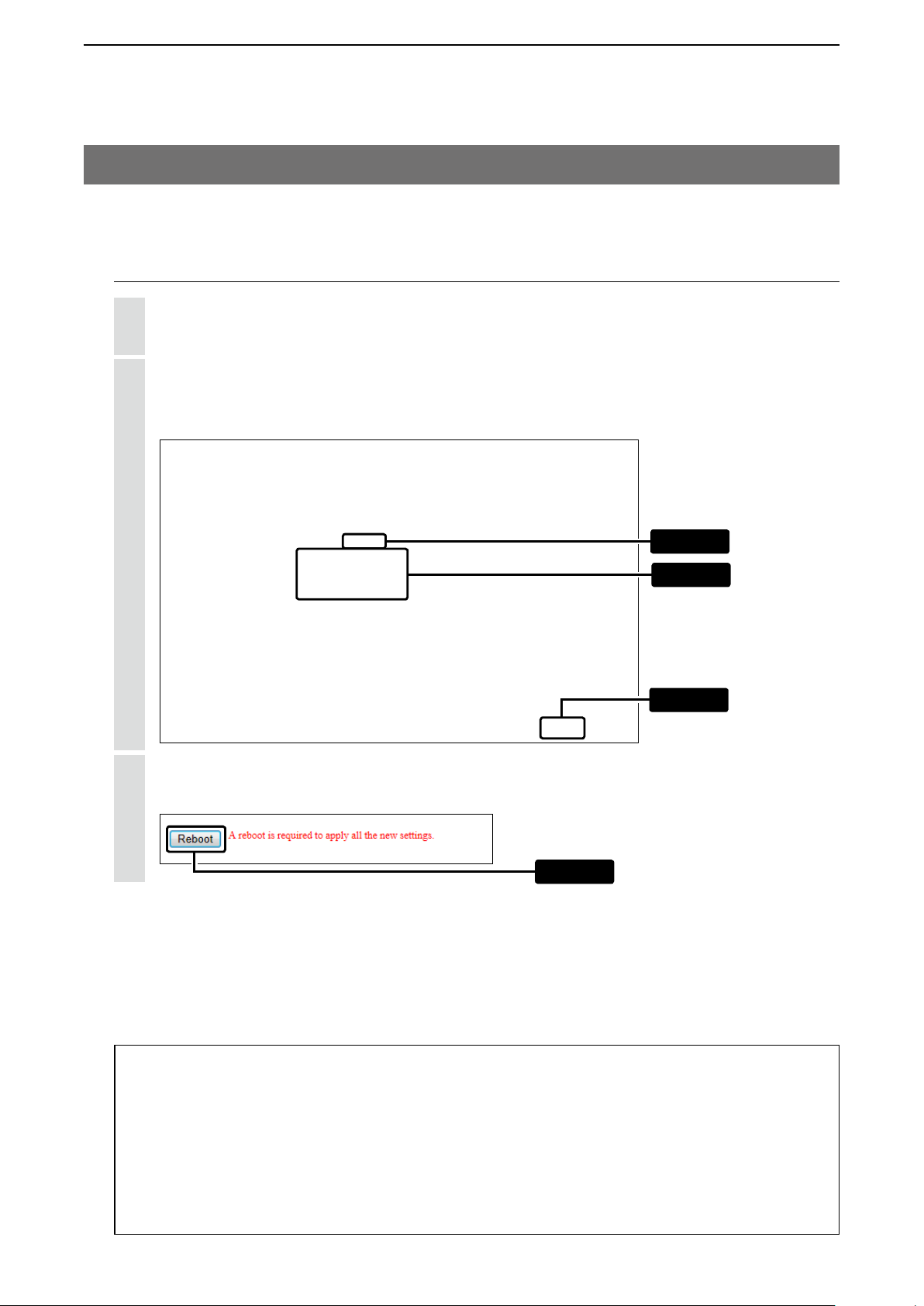
Click <Reboot>.
3
• When you are asked to reboot the IP1000C, follow the instructions.
q Click
w Enter
e Click
Click
About the DHCP server function
The IP1000C’s DHCP server function is disable as the default.
• Before changing this function to “Enable,” make sure that the addresses of the devices on the network don’t overlap or
conflict.
If a DHCP server is already connected to the network, and there is an address conflict, a network problem will occur.
See the Troubleshooting section for possible solutions.
About the maximum number of the IP addresses
Up to 128 addresses can be automatically assigned by the DHCP server function.
Another 32 addresses can be manually assigned.
3-4
Page 55

ABOUT THE SETTING SCREEN
1. About the setting screen ……………………………………………………………………………………………………… 4-4
2. [TOP] Menu …………………………………………………………………………………………………………………… 4-5
M System Status ……………………………………………………………………………………………………………… 4-5
M Network Status …………………………………………………………………………………………………………… 4-5
M Port Status ………………………………………………………………………………………………………………… 4-6
M TRX Status ………………………………………………………………………………………………………………… 4-6
3. [Information] Menu …………………………………………………………………………………………………………… 4-7
M SYSLOG …………………………………………………………………………………………………………………… 4-7
M Memory Usage …………………………………………………………………………………………………………… 4-8
M Traffic Statistics …………………………………………………………………………………………………………… 4-9
4. [Network Settings] Menu …………………………………………………………………………………………………… 4-10
M Host Name ……………………………………………………………………………………………………………… 4-10
M IP Address ……………………………………………………………………………………………………………… 4-11
M DHCP Server …………………………………………………………………………………………………………… 4-12
M Static DHCP …………………………………………………………………………………………………………… 4-14
M Static DHCP Table ……………………………………………………………………………………………………… 4-14
M Routing Table …………………………………………………………………………………………………………… 4-15
M Static Routing …………………………………………………………………………………………………………… 4-16
M List of Static Routing Entries ………………………………………………………………………………………… 4-16
5. [RoIP Settings] Menu ……………………………………………………………………………………………………… 4-17
M Additional Controller Settings ………………………………………………………………………………………… 4-17
M VoIP Extension ………………………………………………………………………………………………………… 4-18
6. [Tenant (Fleet) Settings] Menu …………………………………………………………………………………………… 4-21
M Tenant (Fleet) …………………………………………………………………………………………………………… 4-21
Section
4
4-1
(Continued to the next page.)
Page 56

ABOUT THE SETTING SCREEN
4
(Continued from the previous page)
7. [RoIP Server Settings] Menu ……………………………………………………………………………………………… 4-22
M Call Type Priority ………………………………………………………………………………………………………… 4-22
M Telephone Gateway Interconnection ………………………………………………………………………………… 4-23
M Telephone Gateway Interconnection Entry List ……………………………………………………………………… 4-24
M Telephone Gateway Interconnection Group ………………………………………………………………………… 4-25
M Telephone Gateway Interconnection Group Entry List ……………………………………………………………… 4-26
M Link Setting ……………………………………………………………………………………………………………… 4-27
M Linked Controller List …………………………………………………………………………………………………… 4-28
M Area Setting ……………………………………………………………………………………………………………… 4-29
M Access Point Search …………………………………………………………………………………………………… 4-30
M Area Entry List ………………………………………………………………………………………………………… 4-31
8. [Transceiver Settings] Menu ……………………………………………………………………………………………… 4-32
M Transceiver Management ……………………………………………………………………………………………… 4-32
M Transceiver Settings …………………………………………………………………………………………………… 4-34
M Transceiver Setting Entry List ………………………………………………………………………………………… 4-36
M TRX Batch Setting ……………………………………………………………………………………………………… 4-37
M Transceiver Settings …………………………………………………………………………………………………… 4-38
M Sharing Transceiver Settings ………………………………………………………………………………………… 4-67
M Transceiver Setting List ………………………………………………………………………………………………… 4-67
9. [Common Settings] Menu ………………………………………………………………………………………………… 4-68
M Wireless LAN …………………………………………………………………………………………………………… 4-68
M List of Wireless LAN Entries …………………………………………………………………………………………… 4-74
M ID List Common Settings ……………………………………………………………………………………………… 4-75
M ID List Detail Settings ………………………………………………………………………………………………… 4-75
M Save or Write the ID List Setting ……………………………………………………………………………………… 4-76
M ID List …………………………………………………………………………………………………………………… 4-77
M ID List Entries …………………………………………………………………………………………………………… 4-78
M Message Group ………………………………………………………………………………………………………… 4-79
M Message Group Detail ………………………………………………………………………………………………… 4-79
M Save or Write the Message Setting …………………………………………………………………………………… 4-80
M Messages ……………………………………………………………………………………………………………… 4-81
M Status Settings ………………………………………………………………………………………………………… 4-82
M Profile List ……………………………………………………………………………………………………………… 4-83
M Profile …………………………………………………………………………………………………………………… 4-84
M Profile Batch Setting …………………………………………………………………………………………………… 4-93
4-2
(Continued to the next page.)
Page 57

ABOUT THE SETTING SCREEN
4
(Continued from the previous page)
10. [Destination Settings] Menu ……………………………………………………………………………………………… 4-94
M Destination Setting ……………………………………………………………………………………………………… 4-94
M List of Destination Setting Entries (All Call) ………………………………………………………………………… 4-104
M List of Destination Setting Entries (Group Call) ……………………………………………………………………… 4-104
M List of Destination Setting Entries (Talkgroup Call) ………………………………………………………………… 4-105
M List of Destination Setting Entries (Management Talkgroup Call) ………………………………………………… 4-106
M List of Destination Setting Entries (Individual Call) ………………………………………………………………… 4-107
M List of Destination Setting Entries (Telephone) ……………………………………………………………………… 4-108
M Destination Batch Setting ……………………………………………………………………………………………… 4-109
11. [Management] Menu ……………………………………………………………………………………………………… 4-110
M Administrator Password ………………………………………………………………………………………………… 4-110
M Date and Time …………………………………………………………………………………………………………… 4-111
M Time Zone ……………………………………………………………………………………………………………… 4-112
M NTP ……………………………………………………………………………………………………………………… 4-113
M SNTP Server …………………………………………………………………………………………………………… 4-114
M SYSLOG ………………………………………………………………………………………………………………… 4-115
M SNMP …………………………………………………………………………………………………………………… 4-116
M USB ……………………………………………………………………………………………………………………… 4-117
M Ping Test ………………………………………………………………………………………………………………… 4-118
M Traceroute Test ………………………………………………………………………………………………………… 4-119
M Reboot …………………………………………………………………………………………………………………… 4-120
M Settings Backup ………………………………………………………………………………………………………… 4-121
M Settings Restore ………………………………………………………………………………………………………… 4-121
M Online Settings ………………………………………………………………………………………………………… 4-122
M List of Settings ………………………………………………………………………………………………………… 4-123
M Factory Defaults ………………………………………………………………………………………………………… 4-124
M Firmware Status ………………………………………………………………………………………………………… 4-125
M Online Update …………………………………………………………………………………………………………… 4-126
M Automatic Update ……………………………………………………………………………………………………… 4-127
M Manual Update ………………………………………………………………………………………………………… 4-127
4-3
Page 58
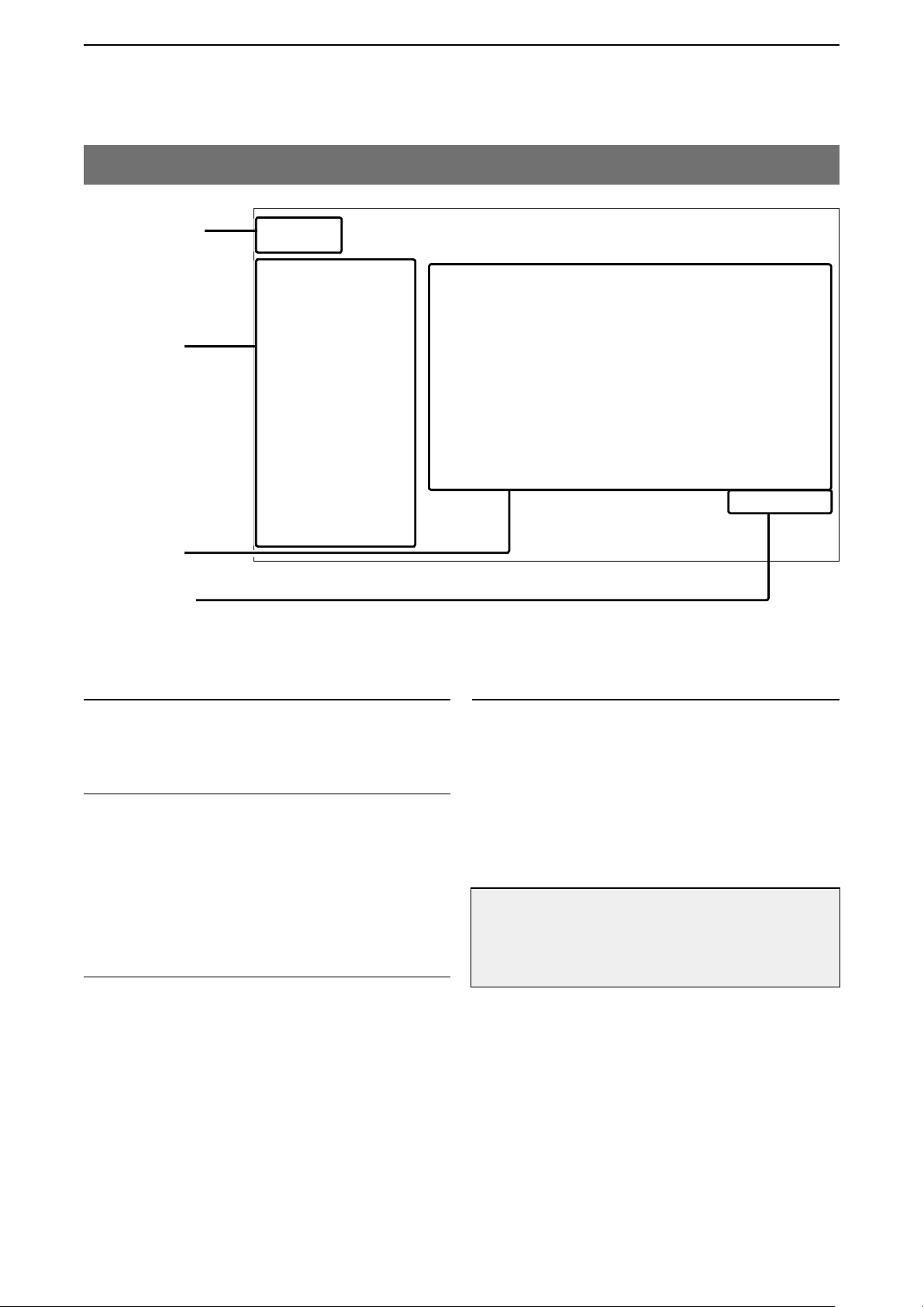
ABOUT THE SETTING SCREEN
4
1. About the setting screen
Icom website link
Setting menu
Setting screen
Setting buttons
Icom website link
Click the Icom logo to open the Icom website, if your PC
is connected to the Internet.
Setting menu
Displays the screen name list on the menu line. When you
click the menu line that “” is displayed at the left of the
title, a list of screen names drops down. Then, you can
click to select the desired screen name.
• If you click “TOP,” all screen names are displayed or
hided.
Setting screen
Displays the settings and values when you click the
screen name.
Setting buttons
Save or cancel setting values.
If “A reboot is required to apply all the new settings.” is
displayed on the screen when you click the [Apply] button,
click the [OK] button.
The IP1000C reboots, and the setting items and values
are updated.
The following message is displayed on the screen while
the IP1000C is rebooting.
Now rebooting.
Wait XX seconds for startup.
If this page doesn’t automatically refresh after rebooting, click [Back].
• If the setting screen does not automatically return, click
[Back] after XX seconds have passed from the “Now re
booting.” message appears.
• Items and buttons may differ, depending on the settings.
-
4-4
Page 59

ABOUT THE SETTING SCREEN
4
2. [TOP] Menu
M System Status
Displays the firmware version and MAC addresses.
(This is only an example.)
• The MAC address is the assigned number peculiar to networking device which it has in each. It is displayed by 12
digits (0090C7XXXXXX).
• The MAC address is also printed on the label on the bottom of the IP1000C.
• The version information of the firmware in every IP100H registered into this IP1000C can be checked on the [TRX
status] field. (p. 4-6).
[TOP]
M Network Status
Displays the network information such as IP address.
(This is only an example.)
4-5
Page 60

ABOUT THE SETTING SCREEN
4
2. [TOP] Menu (continued)
M Port Status
Displays the communication rate and mode for each port.
(This is only an example.)
NOTES
• The IP1000C’s [LAN] ports are auto-negotiation enabled, and can automatically select the optimal speed and duplex
mode if the peer devices are auto-negotiation enabled as well.
• We recommend to always enable auto-negotiation on the peer devices. If a peer device is fixed to full-duplex mode,
auto-negotiation enabled devices (including the IP1000C) may generally take it for half-duplex mode and cannot communicate properly.
[TOP]
M TRX Status
Displays the registered IP100Hs’ or IP100FSs’ information such as the Registration status, IP Address, and Ver-
sion.
(This is only an example.)
4-6
Page 61

ABOUT THE SETTING SCREEN
4
3. [Information] Menu
M SYSLOG
Displays the log information. The latest 500 log entries are displayed.
q
K
(This is only an example.)
q Severity �������� Select the log information to display.
• Enter a check mark and click <Refresh> to display the log entries.
• Remove the check mark and click <Refresh> to hide the entries.
(Default: M DEBUG M INFO M NOTICE)
Note: The selection is not stored, and reset when you leave this screen.
[Information]–[SYSLOG]
w
K
e
K
r
K
w <Refresh> ������� Click to refresh the log screen.
e <Clear> �������� Click to delete all log entries.
Note: All log entries are also deleted when the IP1000C is turned OFF or
initialized.
r <Save> �������� Click to save the log to a PC with a text file (extension: “txt”).
• Click this button, and then select a folder to save the file.
4-7
Page 62
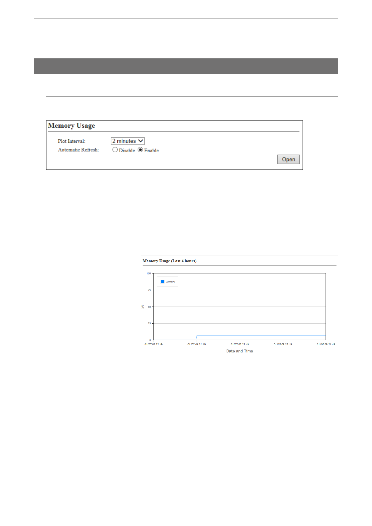
ABOUT THE SETTING SCREEN
4
3. [Information] Menu (continued)
[Information]–[Statistics]
M Memory Usage
Displays a statistical graph of the memory usage.
• These setting items are reset when you leave this screen.
q
K
w
K
q Plot Interval ������ Select the plot interval. (Default: 2 minutes)
w Automatic Refresh ��� Select “Enable” to periodically refresh the graph. (Default: Enable)
• The graph is refreshed according to the set interval in [Plot Interval] (q).
e <Open> �������� Click to open the memory usage graph window.
• The X axis represents the date and time, and the Y axis represents the usage
(%).
e
K
(This is only an example.)
4-8
Page 63
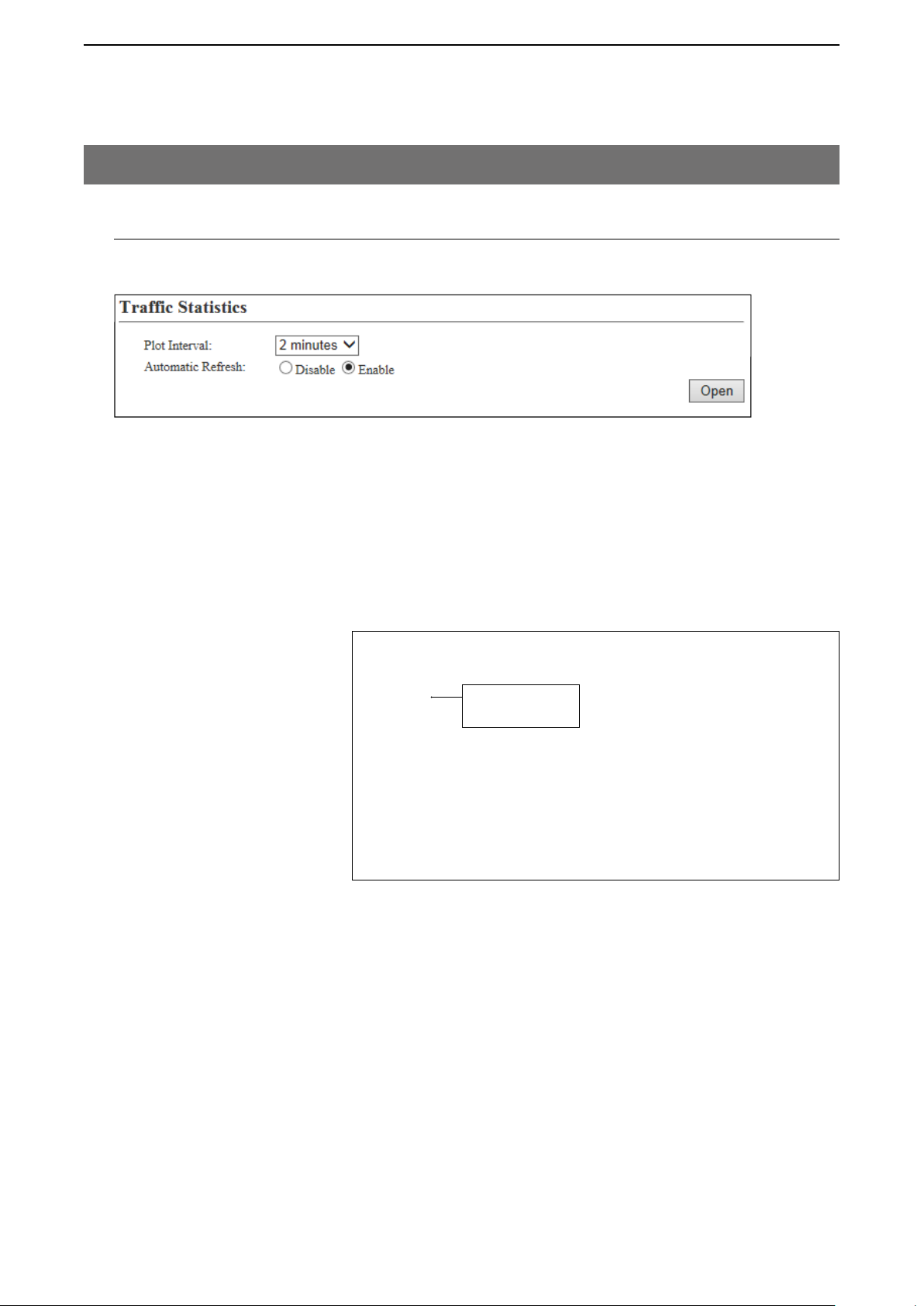
ABOUT THE SETTING SCREEN
4
3. [Information] Menu (continued)
[Information]–[Statistics]
M Traffic Statistics
Displays the traffic graph for LAN port.
• These setting items are reset when you leave this screen.
q
K
w
K
q Plot Interval ������ Select the plot interval. (Default: 2 minutes)
w Automatic Refresh ��� Select “Enable” to periodically refresh the graph. (Default: Enable)
• The graph is refreshed according to the set interval in [Plot Interval] (q).
e <Open> �������� Click to open the traffic graph window.
• The X axis represents the date and time, and the Y axis represents the traffic
(Mbps).
e
K
In: Incoming traffic
Out: Outgoing traffic
(This is only an example.)
4-9
Page 64

ABOUT THE SETTING SCREEN
4
4. [Network Settings] Menu
M Host Name
Enter the host name.
Host Name ������� Enter the host name. (Up to 31 characters) (Default: IP1000C)
Note: The name must start with an alphanumeric character, and must NOT
start or end with a “–.”
[Network Settings]–[IP Address]
4-10
Page 65

ABOUT THE SETTING SCREEN
4
4. [Network Settings] Menu (continued)
[Network Settings]–[IP Address]
M IP Address
Enter the IP1000C’s IP Address.
q
K
w
K
e
K
r
K
t
K
q IP Address ������ Enter the LAN IP address according to your network environment.
(Default: 192.168.0.1)
Note: When using the DHCP Server function, the network part of the IP
address must be the same as that set in the “IP Pool Start Address”
item in the [DHCP Server] menu. (p. 4-12)
y
K
u
K
w Subnet Mask ����� Enter the subnet mask according to your network environment.
(Default: 255.255.255.0)
e Default Gateway ���� If a default gateway device (such as a router) is connected to the LAN port,
enter the device’s IP address.
r Primary DNS server �� Enter the DNS server address specified by your service provider.
If you have two DNS server addresses, enter the primary address.
t Secondary DNS server � Enter the secondary DNS server address, if you have two DNS server
addresses.
y <Apply> ������� Click to apply the entries.
u <Reset> �������� Click to restore the settings.
• You cannot restore after clicking <Apply>.
4-11
Page 66

ABOUT THE SETTING SCREEN
4
4. [Network Settings] Menu (continued)
M DHCP Server
Configure the DHCP Server function.
q
K
w
K
e
K
r
K
t
K
y
K
u
K
i
K
o
K
!0
K
!1
K
[Network Settings]–[DHCP Server]
!2
K
!3
K
q DHCP Server ����� Select “Enable” to use the DHCP Server function. (Default: Disable)
w IP Pool Start Address � Enter the IP pool start address. (Default: 192.168.0.10)
e Pool Size ������� Enter the size of IP pool. (Default: 128)
Up to 128 addresses can be automatically assigned by the DHCP server
Note:
function. Another 32 addresses can be manually assigned.
r Subnet Mask ����� Enter the subnet mask for the IP pool start address set in the “IP Pool Start
Address” item (w). (Default: 255.255.255.0)
t Lease Time ������ Enter the lease time period. (Default: 72)
• Range: 1–9999 (hours)
y Domain Name ����� Enter the network address domain name. (Up to 127 characters)
4-12
Page 67

ABOUT THE SETTING SCREEN
4
4. [Network Settings] Menu
M DHCP Server (continued)
q
K
w
K
e
K
r
K
t
K
y
K
u
K
i
K
o
K
!0
K
!1
K
[Network Settings]–[DHCP Server]
!2
K
!3
K
u Default Gateway ���� Enter the default gateway IP address.
i Primary DNS Server �� Enter the DNS server address specified by your service provider.
If you have two DNS server addresses, enter the primary address.
o Secondary DNS Server � Enter the secondary DNS server address, if you have two DNS server
addresses.
!0 Primary WINS Server � Enter the WINS server’s primary address, if you have two WINS server
addresses, enter the primary address.
!1 Secondary WINS Server Enter the WINS server’s secondary address, if you have two WINS server
addresses.
!2 <Apply> ������� Click to apply the entries.
!3 <Reset> �������� Click to restore the settings.
• You cannot restore after clicking <Apply>.
4-13
Page 68

ABOUT THE SETTING SCREEN
4
4. [Network Settings] Menu (continued)
[Network Settings]–[DHCP Server]
M Static DHCP
Enter MAC and static IP addresses to the DHCP server.
• You can enter up to 32 entries.
Static DHCP ������� Enter the MAC and IP addresses, and then click <Add>.
Note:
Make sure that the addresses of the devices on the network don’t overlap or
conflict. If a DHCP server is already connected to the network, and there is
an address conflict, a network problem will occur. See the Troubleshooting
section for possible solutions.
M Static DHCP Table
Displays the static DHCP entries.
(This is only an example.)
<Delete> �������� Click <Delete> to remove the entry.
4-14
Page 69
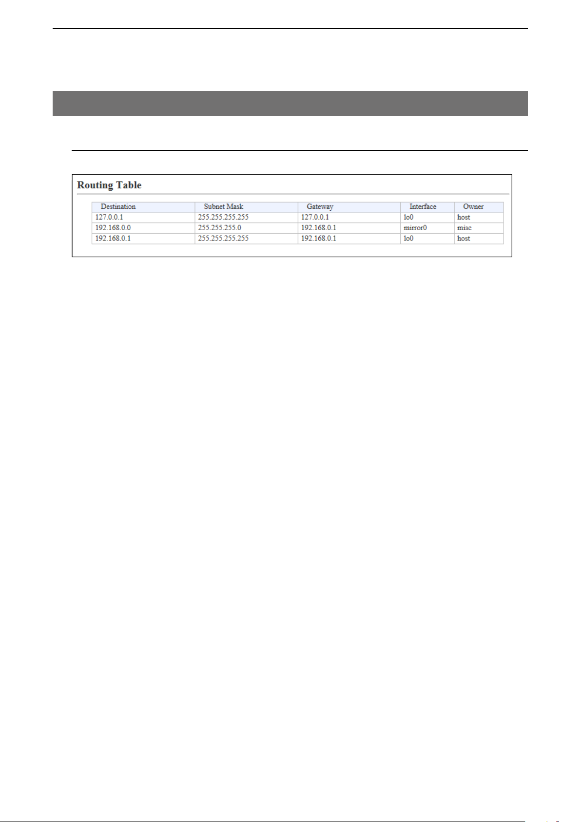
ABOUT THE SETTING SCREEN
4
4. [Network Settings] Menu (continued)
M Routing Table
Displays the routing information.
q
K
(This is only an example.)
q Destination ������
w Subnet Mask �����
e Gateway ������� The route’s gateway address.
r Interface ������� The routing interface.
w
K
The network address of the route's destination network.
The subnet mask of the route's destination network.
• lo0: Loop back interface
• mirror0: LAN
e
K
[Network Settings]–[Static Routing]
r
K
t
K
t Owner �������� The type of routing path.
• static: Static route
• misc: Broadcast frame
• host: Host route
4-15
Page 70

ABOUT THE SETTING SCREEN
4
4. [Network Settings] Menu (continued)
M Static Routing
Enter the static routing destinations.
• You can enter up to 32 entries.
q
K
(This is only an example.)
q Destination ������
w Subnet Mask �����
e Gateway ������� The route’s gateway address.
w
K
The network address of the route's destination network.
The subnet mask of the route's destination network.
e
K
[Network Settings]–[Static Routing]
r
K
r <Add> �������� Click to add the entry.
M List of Static Routing Entries
(This is only an example.)
<Delete> �������� Click <Delete> to remove the entry.
4-16
Page 71

ABOUT THE SETTING SCREEN
4
5. [RoIP Settings] Menu
[RoIP Settings]–[Additional Controller Settings]
M Additional Controller Settings
Configure the Additional Controller Settings.
q
K
w
K
e
K
Example: The default of the [Additional Controller] item is “Disable.” w and e appear when selecting “Enable” in
the [Additional Controller] item.
q Additional Controller �� Select “Enable” in the [Additional Controller] item to communicate with
additional Controllers. (Default: Disable)
When selecting “Enable,” you can communicate with the IP100Hs and the
IP100FS registered to additional controllers.
* Register the destination controller on the [Additional Controller Link] item in
the [RoIP Server Settings] menu.
• When using this Additional Controller Settings, you can link to the bridge
mode’s VE-PG3 for communication.
w Controller Mode ���� Select “Master” for one master Controller. Select [Sub] for the other
Controllers (up to 10 Sub Controllers can be set). (Default: Sub)
When several Controllers are linked and use All call or Group call between
the controllers, the IP1000C whose Controller mode is set to “Sub” cannot
link to the bridge mode’s VE-PG3 to additional controller. In that case, the
VE-PG3 must be linked to the IP1000C whose Controller mode is set to
“Master.”
e Service Port Number �� Enter the port number for receiving audio signals.
Range: “2” to “65534” (only even numbers) (Default: 32000)
• The set port number (RTP) and the port number +1 (RTCP) are used for the
communication.
• This number is also used for the caller port number.
• Do not set the port number which has already been used by another
connection setting.
4-17
Page 72

ABOUT THE SETTING SCREEN
4
5. [RoIP Settings] Menu (continued)
M VoIP Extension
Set the V/RoIP details.
• The items on the [RoIP Settings] screen differ depending on the TOS type setting.
TOS Type: Not used
q
K
w
K
e
K
TOS Type: TOS
q
K
w
K
e
K
r
K
[RoIP Settings]–[VoIP Extension]
t
K
t
K
y
K
y
K
TOS Type: Diffserv
q
K
w
K
e
K
r
K
t
K
y
K
(These are examples when the “Receive Buffer Type” item is set to “Static.”)
q Receive Buffer Type �� Select the buffer type to reduce that the received audio breaks up.
(Default: Dynamic)
• Static
The buffer time is set the “Receive Buffer Size” item below.
• Dynamic
The buffer time is changed, depending on the audio fluctuation.
w Receive Buffer Size �� Select the buffer time to keep the audio from breaking up. (Default: 40)
Shorter value improves the delay, but it may frequently break the audio
signal.
• This item is displayed when the “Receive Buffer Type” item is set to “Static.”
4-18
Page 73

ABOUT THE SETTING SCREEN
4
5. [RoIP Settings] Menu
M VoIP Extension (continued)
TOS Type: Not used
TOS Type: TOS
TOS Type: Diffserv
q
K
w
K
e
K
r
K
q
K
w
K
e
K
[RoIP Settings]–[VoIP Extension]
t
K
t
K
y
K
y
K
q
K
w
K
e
K
r
K
t
K
y
K
e TOS type ������� Select the TOS (Type-Of Service) format. (Default: TOS)
• Not used
Does not use the TOS function.
• TOS
Sends the VoIP packets to TOS field (8 bits) in the IP header using the
TOS format.
• Diffserv
Sends the VoIP packets to TOS field (8 bits) in the IP header using the
Diffserv (Differentiated Service) format.
4-19
Page 74

ABOUT THE SETTING SCREEN
4
5. [RoIP Settings] Menu
M VoIP Extension (continued)
TOS Type: Not used
TOS Type: TOS
TOS Type: Diffserv
q
K
w
K
e
K
r
K
q
K
w
K
e
K
[RoIP Settings]–[VoIP Extension]
t
K
t
K
y
K
y
K
q
K
w
K
e
K
r
K
t
K
r Media (RTP) ������ Select the Priority level and Service type of the sent VoIP packets.
• Priority Level
Set the TOS priority level between 0 to 7 in decimal. (Default: 7)
• Service Type
Set the TOS service type code between 0 to 15 in decimal. (Default: 0)
• DSCP
Set the DSCP (Differentiated Services Code Point) code between 0 to 63 in
decimal. (Default: 56)
t <Apply> ������� Click to apply the entries.
y
K
y <Reset> �������� Click to restore the settings.
• You cannot restore after clicking <Apply>.
4-20
Page 75

ABOUT THE SETTING SCREEN
4
6. [Tenant (Fleet) Settings] Menu
[Tenant (Fleet) Settings]–[Tenant (Fleet)]
M Tenant (Fleet)
The tenant (fleet) divides the IP100Hs or IP100FSs which belong to this IP1000C for a system management pur-
pose. (Example: Security company/Commissioned company)
• The terminals cannot communicate among different tenants (fleets).
q
K
e
w
K
q Tenant (Fleet) Number � Select the tenant (fleet) number that is registered or edited.
w Tenant (Fleet) Name �� Enter the tenant (fleet) name. (Up to 31 characters) (Default: Tenant1)
• The tenant (fleet) name is displayed on the following menus.
- RoIP Server Settings
- Transceiver Settings
- Common Settings (Except Wireless LAN menu)
- Destination Settings
K
r
K
(Default: 1)
(This is only an example.)
e <Apply> ������� Click to apply the entries.
r <Reset> �������� Click to restore the settings.
• You cannot restore after clicking <Apply>.
The Tenant (Fleet) name is displyed here
4-21
Page 76

ABOUT THE SETTING SCREEN
4
7. [RoIP Server Settings] Menu
M Call Type Priority
Select the priority level of the call types.
q
(This is only an example.)
q
Call type Priority (High to Low)
w <Apply> ������� Click to apply the entries.
e <Reset> �������� Click to restore the settings.
Select the priority level of the call types.
• You cannot restore after clicking <Apply>.
[RoIP Server Settings]–[Call Type Priority]
w e
(Default: Telephone – All – Individual – Group)
4-22
Page 77

ABOUT THE SETTING SCREEN
4
7. [RoIP Server Settings] Menu (continued)
[RoIP Server Settings]–[Telephone Gateway Interconnection]
M Telephone Gateway Interconnection
Set the Telephone Gateway Interconnection with a VE-PG3.
q
K
w
K
e
K
r
K
K
(This is only an example.)
q No. ���������� Select the number that is registered to a device.
• Up to 20 devices can be registered.
w Destination Address ��
Enter the destination device’s IP address or domain name. (Up to 63
characters)
t
K
y
K
e Destination Port Number
r Service Port Number ��
t <Apply> ������� Click to apply the entries.
y <Reset> �������� Click to restore the settings.
Enter the destination VE-PG3’s port number.
Range: ‘2’ to ‘65534’ (only even numbers)
• The set port number (RTP) and the port number +1 (RTCP) are used for the
communication.
Enter the port number for receiving audio signals.
Range: ‘2’ to ‘65534’ (only even numbers)
• The set port number (RTP) and the port number +1 (RTCP) are used for the
communication.
• This number is also used for the caller port number.
• Do not set the port number which has already been used by another
connection setting.
• You cannot restore after clicking <Apply>.
4-23
Page 78

ABOUT THE SETTING SCREEN
4
7. [RoIP Server Settings] Menu (continued)
[RoIP Server Settings]–[Telephone Gateway Interconnection]
M Telephone Gateway Interconnection Entry List
The list of the registered device for the Telephone Gateway Interconnection.
q
K
(This is only an example.)
q <Edit> �������� Click to edit the setting on the [Telephone Gateway Interconnection] field.
w <Delete> ������� Click to delete the selected entry.
• After clicking <Delete>, the content cannot be recalled.
w
K
e
K
e <Delete All> ������ Click to delete all the entries.
• After clicking <Delete All>, the contents cannot be recalled.
4-24
Page 79

ABOUT THE SETTING SCREEN
4
7. [RoIP Server Settings] Menu (continued)
[RoIP Server Settings]–[Telephone Gateway Interconnection]
M Telephone Gateway Interconnection Group
If the courses of the Telephone Gateway Interconnection to the VE-PG3s are made into a group, the unused
course in the group can be selected to dispatch.
q
w
e
r
t
K
K
(This is only an example.)
q No. ���������� Select the number that is registered to a group.
• Up to 20 groups can be registered.
w Name ���������
e Telephone Gateway Interconnection Number
����������� Select the Telephone Gateway Interconnection to register to the group.
r <Add> �������� Click to add the entries.
t <Reset> �������� Click to restore the settings.
Enter the group name. (Up to 31 characters)
• You cannot restore after clicking <Add>.
4-25
Page 80

ABOUT THE SETTING SCREEN
4
7. [RoIP Server Settings] Menu (continued)
[RoIP Server Settings]–[Telephone Gateway Interconnection]
M Telephone Gateway Interconnection Group Entry List
The list of the registered Telephone Gateway Interconnection group.
q
K
(This is only an example.)
q <Edit> �������� Click to edit the setting on the [Telephone Gateway Interconnection Group]
field.
w <Delete> ������� Click to delete the selected entry.
• After clicking <Delete>, the content cannot be recalled.
w
K
e
K
e <Delete All> ������ Click to delete all the entries.
• After clicking <Delete All>, the contents cannot be recalled.
4-26
Page 81

ABOUT THE SETTING SCREEN
4
7. [RoIP Server Settings] Menu (continued)
[RoIP Server Settings]–[Additional Controller Link]
M Link Setting
This is a setting to link with other IP1000Cs or VE-PG3s (Bridge mode).
q
w
e
r
(This is only an example.)
q No. ���������� Select a number from 1 to 100 to register the IP1000Cs
mode) to establish a link.
• Up to 100 links can be made.
t
K
y
K
or VE-PG3s (Bridge
w Name ���������
e Destination Address �� Enter the destination device’s IP address or domain name. (Up to 63
r Destination Port Number Enter the destination IP1000C’s service port number of the Additional
t <Apply> ������� Click to apply the entries.
y <Reset> �������� Click to restore the settings.
Enter the group name. (Up to 31 characters)
characters)
Controller Settings (p. 4-17).
Range: “2” to “65534” (only even numbers)
• The set port number (RTP) and the port number +1 (RTCP) are used for the
communication.
• You cannot restore after clicking <Apply>.
4-27
Page 82

ABOUT THE SETTING SCREEN
4
7. [RoIP Server Settings] Menu (continued)
[RoIP Server Settings]–[Additional Controller Link]
M Linked Controller List
The [Linked Controller List] is a list of the destination IP addresses and port numbers registered to this IP1000C.
q
K
(This is only an example.)
q <Edit> �������� Click to edit the setting on the [Link Setting] field.
w <Delete> ������� Click to delete the selected entry.
• After clicking <Delete>, the content cannot be recalled.
e <Delete All> ������ Click to delete all the entries.
• After clicking <Delete All>, the contents cannot be recalled.
w
K
e
K
4-28
Page 83

ABOUT THE SETTING SCREEN
4
7. [RoIP Server Settings] Menu (continued)
[RoIP Server Settings]–[Area Call]
M Area Setting
The Area call function limits the communication with the devices in the specified area.
When an IP100H makes an All call or Group call using the Area call function, it calls other IP100Hs or IP100FSs in
the same area.
• If you want to use the Area call from an IP100FS, specify the area by selecting the desired access points.
q
w
e
(This is only an example.)
r
K
t
K
q No. ���������� Select the number that is registered to the Area call.
• Up to 20 calls can be registered.
w Name ���������
e BSSID �������� Enter the 12 digit BSSID of the wireless access point in the area. (Example:
r <Apply> ������� Click to apply the entries.
t <Reset> �������� Click to restore the settings.
The IP100H makes All call in the area
Example: The wireless access points “Sales” and “Accounts” are registered in the same area. The access
point “Parts” is registered in the different area.
In that case, two IP100Hs in the same area receive the call, but the IP100H in the different area
will not receive it.
Enter the area name. (Up to 31 characters)
Sales and Accounts)
• Up to 20 access points can be registered to the area.
• You cannot restore after clicking <Apply>.
All call
Sales
Accounts
4-29
Parts
The settings of the “Transceiver Settings”
item are necessary to use the Area call
function for the each IP100H.
Page 84

ABOUT THE SETTING SCREEN
4
7. [RoIP Server Settings] Menu (continued)
[RoIP Server Settings]–[Area Call]
M Access Point Search
The IP1000C can search an access point on the network to register the access point for Area Call.
*Icom guarantees this function only for the AP-90M. (As of February 2018)
q
K
w
K
(This is only an example.)
q IP Address Range ��� Click the <Search> button after entering the IP address range of the access
points.
The searched access point information will be displayed in the list.
e
K
r
K
y
K
t
K
w Selection Box ����� Click a selection box to add a check mark for registering a searched access
point.
*By clicking the [All] Box, you can select or cancel all access points in the list.
e Name ��������� An area name, which is selected in the [Number] item is displayed.
*An area name is registered on the [Number] item in the [Area] setting.
r Number �������� Select an area to register from a “Number” item of [Area Setting].
t <Add> �������� Click the <Add> button to register a searched access point in the [access
point Search] setting.
y <Apply selection> ��� Click the <Apply selection> button to register a selected access point in the
selection box (w) item.
4-30
Page 85

ABOUT THE SETTING SCREEN
4
7. [RoIP Server Settings] Menu (continued)
M Area Entry List
The list of the registered Area setting.
(This is only an example.)
q <Edit> �������� Click to edit the setting on the [Area Setting] field.
[RoIP Server Settings]–[Area Call]
q
K
w
K
e
K
w <Delete> ������� Click to delete the selected entry.
• After clicking <Delete>, the content cannot be recalled.
e <Delete All> ������ Click to delete all the entries.
• After clicking <Delete All>, the contents cannot be recalled.
4-31
Page 86

ABOUT THE SETTING SCREEN
4
8. [Transceiver Settings] Menu
[Transceiver Settings]–[Transceiver Management]
M Transceiver Management
The IP1000C can monitor the registered IP100Hs and IP100FSs. And if necessary, the IP1000C can reboot the
registered IP100Hs at the same time.
w
q
K
o
K
!0
K
(This is only an example.)
*An IP100H is displayed in bold when the setting is changed and the reboot is required.
q Selection Box ����� Click a selection box to add a check mark for the IP100H to reboot.
* You cannot select the IP100FS, or the IP100H that “Disconnected” in the
[Registration Status] is displayed.
*By clicking the [All] Box, you can select or cancel all IP100Hs in the list.
K
e
K
r
K
t
K
y
K
i
K
u
K
w Registration Status �� Displays the IP100Hs’ or IP100FSs’ Registration Status either the
“Connected” or “Disconnected.”
• If the IP100H is turned OFF or IP100FS’s application is not running,
displays “Disconnected.”
• When the IP1000C sends the reboot command to the IP100H from the
[Transceiver Management] menu, the following status are displayed:
“Receiving reboot command,” “Reboot command reception success,”
“Reboot command reception failed,” “Ready to reboot” “Rebooting,”
“Updating,” “Update failed,” “Downloading,” “Status notification failed,” and
“Low battery.”
e IP Address ������ Displays the IP Addresses of the IP100Hs or IP100FSs.
• While the “Registration Status” displays “Disconnected,” “–” is displayed.
r Current Status ���� Displays the Current Status of the IP100Hs. (Example: In the meeting)
• If the Status function is set to OFF, “–” is displayed.
• If you click the <Refresh> button (u), the latest status will be displayed.
• When the IP100H is remotely locked by the IP100FS, and it cannot
communicate with others or cannot transmit, “Transmit and receive disabled”
or “Transmit disabled” is displayed.
•If the IP100H is sending an emergency call, “Emergency” is displayed.
4-32
Page 87

ABOUT THE SETTING SCREEN
Blinks
4
8. [Transceiver Settings] Menu
[Transceiver Settings]–[Transceiver Management]
M Transceiver Management (continued)
y
K
o
K
!0
K
q
K
w
K
e
K
r
K
t
K
(This is only an example.)
*An IP100H is displayed in bold when a setting is changed, a reboot is required.
t Talkgroup ������� Displays the Talkgroup IDs that are selected by the IP100Hs or IP100FSs.
• While the IP100H or IP100FS does not select the Talkgroup, or
“Registration Status” displays “Disconnected,” “–” is displayed.
i
K
u
K
y Location ������� Displays the BSSIDs of the wireless access points that the IP100Hs are
connected to.
• While the “Registration Status” displays “Disconnected,” “–” is displayed.
u <Refresh> ������� Click the <Refresh> button to renew [Registration Status].
i Version �������� Displays the version of the IP100Hs or IP100FSs that are registered to the
IP1000C.
• While the “Registration Status” displays “Disconnected,” “–” is displayed.
o Manual Update ���� Select “Enable” to manually update the IP100H firmware when the IP1000C
sends the reboot command (!0) to the IP100H.
When the IP100H is ready to update the firmware, “F” blinks on the display
and then the IP100H automatically reboots and starts the firmware update.
F
1/24 16:57
Sales8
Updating
* When the IP100H has failed preparation of firmware update, the IP100H
does not reboot automatically. If necessary, send reboot command to the
IP100H.
!0 Manual Reboot ���� Click the <Execute> button to reboot all of the IP100Hs that are selected in
the selection box (
q).
4-33
Page 88

ABOUT THE SETTING SCREEN
4
8. [Transceiver Settings] Menu (continued)
M Transceiver Settings
Registers or edits the IP100H or IP100FS settings.
• After the setting is completed, you must reboot the IP100H.
q
w
e
r
t
y
u
i
(This is only an example.)
[Transceiver Settings]–[Transceiver Registration]
o
K
!0
K
q TRX No. ������� Selects the number that the IP100H or IP100FS is registered to.
Up to 100 terminals can be registered.
• Depending on the IP1000C versions, up to 20 terminals can be registered.
w Transceiver Model ��� Select either the IP100H or IP100FS. (Default: IP100H)
e Name ��������� Enter the transceiver name. (Up to 31 characters)
r Unit ID �������� Enter the 4 digit individual number between 0001 to 9999. (Default: 0001)
t Password ������� Enter the password to access to the IP1000C. (Default: iptrx)
• Up to 12 characters, lower or upper letters, numbers, symbols can be used.
y Transceiver Port Number Enter the port number that the IP100H uses to communicate with the
IP1000C. (UDP port)
• The set port number (RTP) and the port number +1 (RTCP) are used for the
communication.
• We recommend to use default port number, if it is not problem.
• The default number differs, depending on the [TRX No.] as shown below.
(Default: TRX No. 1 (30000), TRX No. 2 (30002), TRX No. 3 (30004),
TRX No. 4 (30006), • • • • • • • • • • • • • •, TRX No. 100 (30198)
• Setting range: Even numbers between 2 and 59998.
(Some numbers may not be acceptable.)
• Do not set the port number which has already been used by another
connection setting.
• When the “Transceiver Model” item (w) is selected “IP100FS,” this item is
not displayed.
4-34
Page 89

ABOUT THE SETTING SCREEN
4
8. [Transceiver Settings] Menu
[Transceiver Settings]–[Transceiver Registration]
M Transceiver Settings (continued)
q
w
e
r
t
y
u
i
(This is only an example.)
u Server Port Number �� Enter the port number that the IP1000C uses to communicate with the
IP100H or IP100FS. (UDP port)
• The set port number (RTP) and the port number +1 (RTCP) are used for the
communication.
• We recommend to use default port number, if it is not problem.
• The default number differs, depending on the [TRX No.] as shown below.
(Default: TRX No. 1 (30000), TRX No. 2 (30002), TRX No. 3 (30004),
TRX No. 4 (30006), • • • • • • • • • • • • • •, TRX No. 100 (30198)
• Setting range: Even numbers between 2 and 65534.
(Some numbers may not be acceptable.)
• Do not set the port number which has already been used by another
connection setting.
o
K
!0
K
i Profile �������� Select the Profile number that the IP100H or IP100FS belongs to. (Default: 1)
• 1 to 100 are selectable.
• Set the Profile setting in the [Common Settings] menu, such as ID list,
message or Receive notification tone settings.
o <Add> �������� Click to add the entries.
!0 <Reset> �������� Click to restore the settings.
• You cannot restore after clicking <Add>.
4-35
Page 90

ABOUT THE SETTING SCREEN
4
8. [Transceiver Settings] Menu (continued)
[Transceiver Settings]–[Transceiver Registration]
M Transceiver Setting Entry List
The list of the registered IP100Hs or IP100FSs.
q
K
e
K
(This is only an example.)
q Selection Box ����� Click a selection box to add a check mark to delete an entry.
*By clicking the [All] box, you can select or cancel all entries in the list.
r
K
t
K
y
K
w
K
w <Delete> ������� Click to delete the selected entry.
• After clicking <Delete>, the content cannot be recalled.
e <Apply> ������� Click to apply the entries.
r <Reset> �������� Click to restore the settings.
• You cannot restore after clicking <Apply>.
t <Delete> ������� Click to delete an entry, which you select in the selection box.
*After an entry is deleted, the entry cannot be recalled.
y <Delete All> ������ Click to delete all the entries.
• After clicking <Delete All>, the contents cannot be recalled.
4-36
Page 91

ABOUT THE SETTING SCREEN
4
8. [Transceiver Settings] Menu (continued)
[Transceiver Settings]–[Transceiver Registration]
M TRX Batch Setting
You can register consecutive Destination IDs collectively. Or you can copy the Destination ID contents to the other
ID.
q
w
e
q Range �������� Enter a range of collective Destination IDs.
<Add>
By clicking the <Add> button, you can register a consecutive Destination IDs
collectively in the box.
* If a Destination ID is already registered, “Duplicate IDs” is displayed.
w Refer to �������� Select the default settings or the programmed settings to refer to.
(Default: Default)
e Profile �������� Select a profile number, which IP100Hs or IP100FSs belong to. (Default: 1)
• 1 to 100 are selectable.
You can set an ID List, Message List, or Notification beep setting of each
profile in the [Common Settings] menu.
4-37
Page 92

ABOUT THE SETTING SCREEN
4
8. [Transceiver Settings] Menu (continued)
[Transceiver Settings]–[Transceiver Settings]
M Transceiver Settings
Individually assign the functions or set the receive notification tone to the registered IP100H.
• After the setting is completed, you must reboot the IP100H.
q
w
e
r
t
(This is only an example.)
q Unit ID �������� Select the Individual number (Name) that the IP100H is edited.
• Only the individual numbers for the IP100H are selectable.
The individual number that the “Transceiver Model” item on the [Transceiver
Registration] screen is set to “IP100FS,” cannot be selected.
w Display Item ������ Select whether the IP100H displays the Date and Time or its Name in the
standby mode. (Default: Date and Time)
• If the “Name” item on the [Transceiver Registration] screen has not been
entered, and this setting is set to “Name,” the IP100H displays the individual
number.
e BackLight ������� Select the IP100H backlight function. (Default: Auto)
• OFF
The backlight does not light.
• ON
The backlight lights continuously.
• Auto
The backlight lights when an operation is performed, and goes out after 5
seconds.
r Tx Inhibit ������� Select “Enable” to inhibit the IP100H’s transmission. (Default: Disable)
* When this setting is set to “Enable,” the IP100H cannot also transmit with an
optional microphone or using VOX function as well.
t PTT Lock ������� Select “Enable” to lock the IP100H’s PTT switch. (Default: Disable)
* When this setting is set to “Enable,” the IP100H cannot transmit by holding
its PTT switch, but it can be transmitted with an optional microphone or
using VOX function as well.
4-38
Page 93
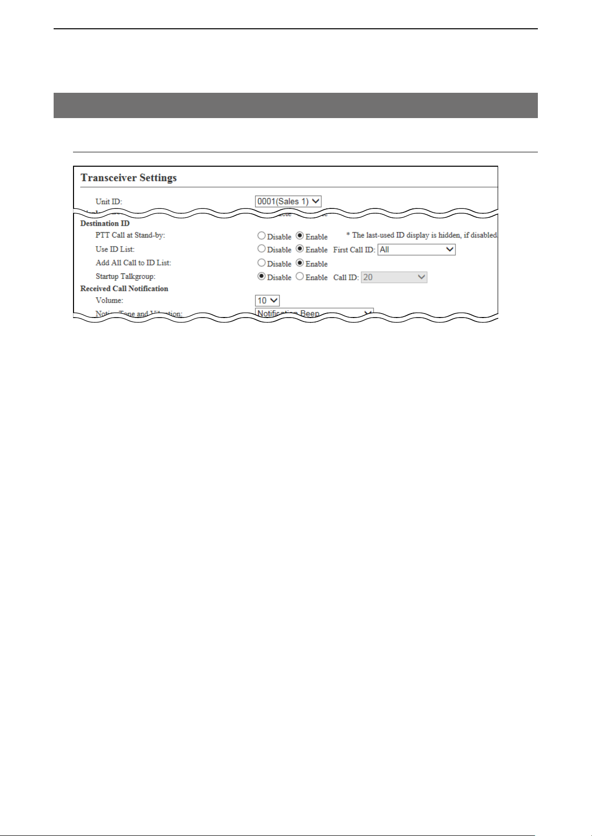
ABOUT THE SETTING SCREEN
4
8. [Transceiver Settings] Menu
[Transceiver Settings]–[Transceiver Settings]
M Transceiver Settings (continued)
y
u
i
o
!0
(This is only an example.)
y PTT Call at Stand-by �� Select whether the IP100H displays the Destination ID (Call type) in the
standby mode or not. (Default: Enable)
• Enable
The Destination ID (Call type) is displayed on the standby mode.
* When the PTT on the IP100H is pushed, the IP100H calls the displayed ID
(Call type).
• Disable
The Destination ID (Call type) is not displayed on the standby mode.
* The Destination ID (Call type) is displayed when you select the ID using
function keys.
4-39
Page 94

ABOUT THE SETTING SCREEN
4
8. [Transceiver Settings] Menu
[Transceiver Settings]–[Transceiver Settings]
M Transceiver Settings (continued)
y
u
i
o
!0
(This is only an example.)
u Use ID List ������ Select whether or not the IP100H uses the ID list. (Default: Disable)
• Disable
The call type is fixed to that which is selected in the “Call Type” item, as
(Address) key
below, even if you push the [
•
If you set the Call Type to “Individual” or “Group,” enter the 4 digit
destination ID in the “Destination ID” item. (Default: All)
] key on the IP100H.
• Even if “Disable” is selected, the IP100H displays a received ID in the ID
list.
• Enable
The call type is changed by pushing the [
Select First Call ID from All or an ID number (1 to 50) that is displayed when the
IP100H is turned ON, and the Call type.
• The ID list is selected on the Common Setting screen.
i Add All Call to ID List � Select whether or not to display All Call in the ID list of the IP100H.
(Default: Disable)
• Disable
Does not display “All” in the ID list.
•
When “Disable” is selected in the [Add All Call to ID List] item, you cannot
select an All call using the [
• Enable
• When the “User ID List” item (u) is set to “Enable,” set the “Add All Call to
ID List” and the“Startup Talkgroup” items.
] key.
] key on the IP100H.
4-40
Page 95
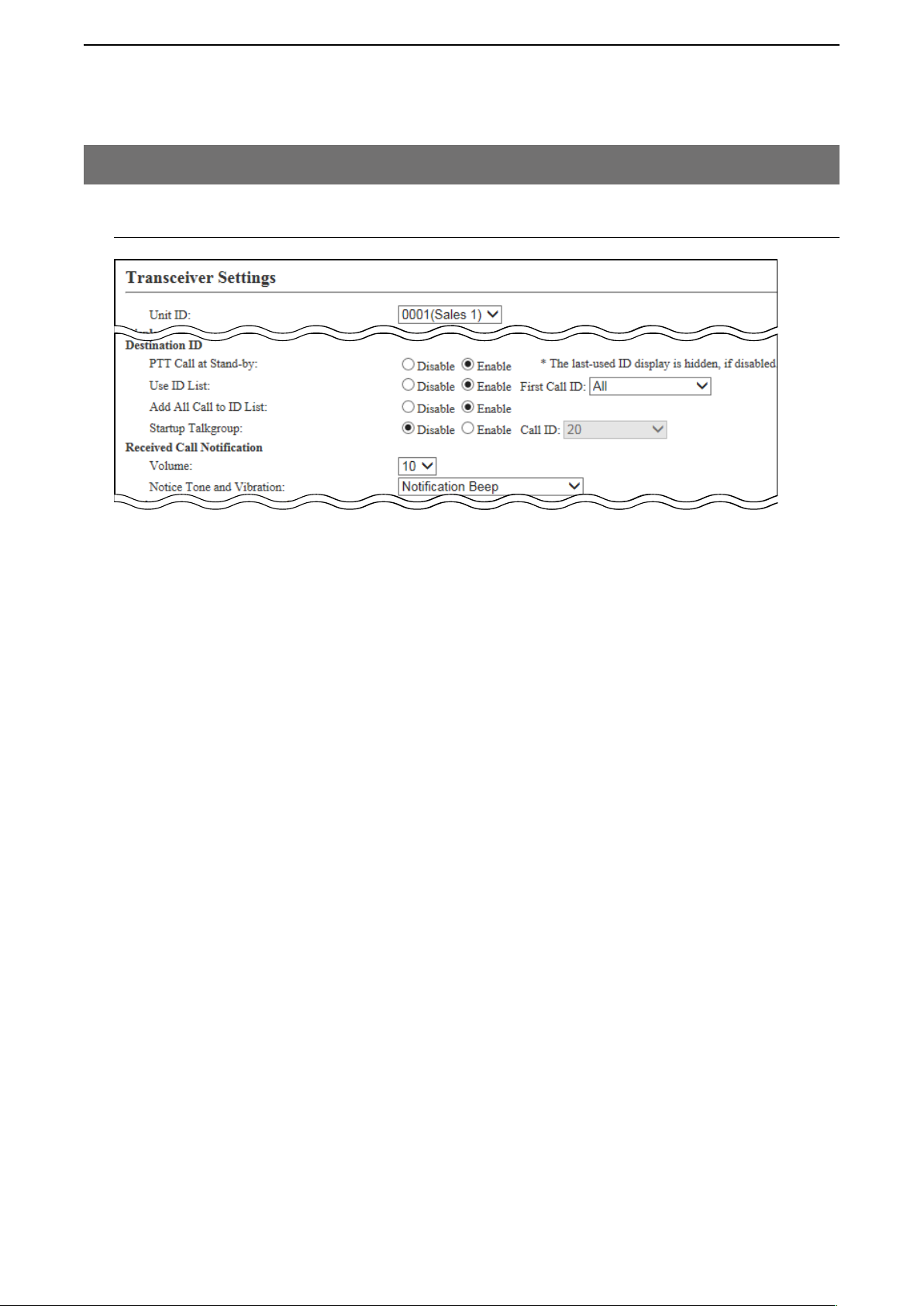
ABOUT THE SETTING SCREEN
4
8. [Transceiver Settings] Menu
[Transceiver Settings]–[Transceiver Settings]
M Transceiver Settings (continued)
y
u
i
o
!0
!1
(This is only an example.)
o Startup Talkgroup ��� Select a talkgroup if you want to set the IP100H to join a talkgroup when you
turn ON the power. (Default: Disable)
• Disable
The IP100 starts up without joining any talkgroup. The ID that is set in the
“First Call ID” in the “User ID List” item (u) is displayed when the IP100H is
turned ON.
• Enable
The IP100 joins the selected talkgroup when it is turned ON.
• When the “User ID List” item (u) is set to “Disable,” this item is not
displayed.
!0 Volume �������� Set the beep level when the IP100H receives a Call or message to between 0
and 32. (Default: 10)
• When this setting set to “0,” the notification beep becomes OFF.
• The notification beep is individually set for the Call type or message in the
“Receive Notification Tone” item on the [Common Settings] screen.
!1 Notice Tone and Vibration Set the action when the IP100H receives a Call or message to between
“Notification Beep,” “Vibration” and “Notification Beep + Vibration.”
(Default: Notification Beep)
• Notification Beep
When the IP100H receives a Call or message, the specified Notification
beep sounds depending on the Call or message.
The notification beep is set in the “Receive Notification Tone” item on the
[Common Settings] screen.
• Vibration
When the IP100H receives a Call or message, it vibrates for notification.
• Notification Beep + Vibration
When the IP100H receives a Call or message, the Notification beep
sounds and it vibrates for notification.
4-41
Page 96
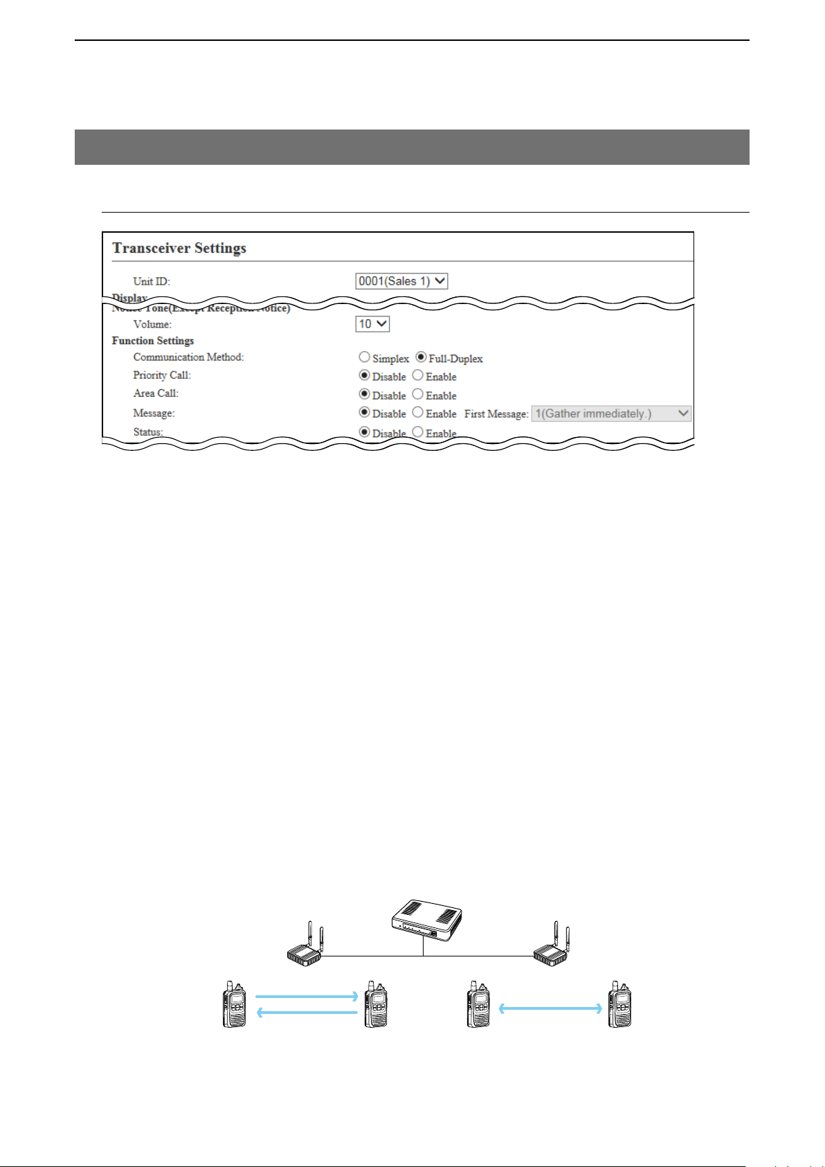
ABOUT THE SETTING SCREEN
4
8. [Transceiver Settings] Menu
[Transceiver Settings]–[Transceiver Settings]
M Transceiver Settings (continued)
!2
!3
!4
!5
!6
!7
(This is only an example.)
!2 Volume
(Except Reception Notice) Set the beep level when the IP100H transmits a Call or connecting to the
IP1000C to between 0 and 32. (Default: 10)
• When this setting is set to “0,” the notification beep becomes OFF.
* Depending on the [Common Settings], the IP100H sounds beeps when the
IP100H is transmitting or connecting to the IP1000C.
!3 Communication Method Select the communication method that the IP100H uses.
(Default: Full-Duplex)
• Simplex
Toggles the transmission (Talker) and reception (Listener) by turns for
communication.
• Full-duplex
Operates the transmission and reception simultaneously like a telephone.
• When connecting the optional microphone to the IP100H, you can
operate the IP100H like a telephone.
Simplex and Full-duplex
IP1000C
Wireless
access point
Simplex
IP100H
Full-duplex
4-42
Page 97

ABOUT THE SETTING SCREEN
4
8. [Transceiver Settings] Menu
[Transceiver Settings]–[Transceiver Settings]
M Transceiver Settings (continued)
!2
!3
!4
!5
!6
!7
(This is only an example.)
!4 Priority Call ������ Select whether the IP100H uses the Priority Call or not. (Default: Disable)
The priority levels of the Call types are in the following order.
Priority
High
Priority Call type
level
Fixed
Telephone
Emergency (High)
Emergency (Normal)
All Call (High)
Individual Call (High)
Selectable*
Group Call (High)
All Call (Normal)
Individual Call (Normal)
Low
Group Call (Normal)
* Selectable in the Call Type Priority item in the [RoIP Server] screen in the
[RoIP Server settings] menu.
• The priority is given to the first call between calls with the same priority
level.
• The reply call follows the priority level of the talk side.
Priority
Call
—
Enable —
Disable —
Enable
Enable Includes from an IP100FS
Enable
Disable Includes the Area Call
Disable —
Disable Includes the Area Call
For telephone communication
Includes the Area Call or
calling from an IP100FS
Includes the Area Call or
calling from an IP100FS
Remarks
Change the target during communication with the Priority Call function enabled
IP1000C
Wireless
access point
IP100H
Group Call
Making an Individual Call
during communication
Group Call
4-43
Individual Call
Page 98

ABOUT THE SETTING SCREEN
IP100H makes an All Call with the Area Call function
4
8. [Transceiver Settings] Menu
[Transceiver Settings]–[Transceiver Settings]
M Transceiver Settings (continued)
!2
!3
!4
!5
!6
!7
(This is only an example.)
!5 Area Call ������� Select whether the IP100H uses the Area Call or not. (Default: Disable)
When the IP100H calls All Call or Group Call using the Area Call function, it
calls only other IP100Hs or IP100FSs in the same area that it connects to the
wireless access point.
IP1000C
Sales Accounts Parts
All Call
IP100FS calls the All Call with the Area Call function
Wireless
access point
IP100H
The wireless access points that the
IP100H is included in with the Area Call
function, are set on the [Area Call] screen
in the [RoIP Server Settings] menu.
(Example: For Sales and For Accounts)
When the IP100FS uses the Area Call
function, the IP100FS can call IP100Hs that
are in the communication range of the
access points assigned to the Area Call.
Select the access point in the [Location], the
Call type (Individual, Group, All, Area or
Telephone) and names are displayed.
4-44
Page 99

ABOUT THE SETTING SCREEN
IP100H transmits a message
4
8. [Transceiver Settings] Menu
[Transceiver Settings]–[Transceiver Settings]
M Transceiver Settings (continued)
!2
!3
!4
!5
!6
!7
(This is only an example.)
!6 Message ������� Select whether the IP100H can send the messages or not. (Default: Disable)
When “Enable” is selected, push [FUNC] on the IP100H once to enter the
Message selection screen.
• Up to 10 messages of 32 characters or less can be programmed on the
[Messages] screen in the [Common Settings] menu.
• Select the message number 1 to 10 in the “First Message” item that is
registered on the [Message] screen.
IP1000C
Message
All
Gather immedi
Message selection screen
(TX)
IP100FS transmits a message
Selected Call type Selected or edited message
IP100H
All Call
4-45
Wireless
access point
Blinks
Scrolls
1/25 12:57
All Gather imme
Received messege screen
The IP100FS can store up to 100 messages
in each Site.
You can edit the stored messages.
(RX)
Page 100
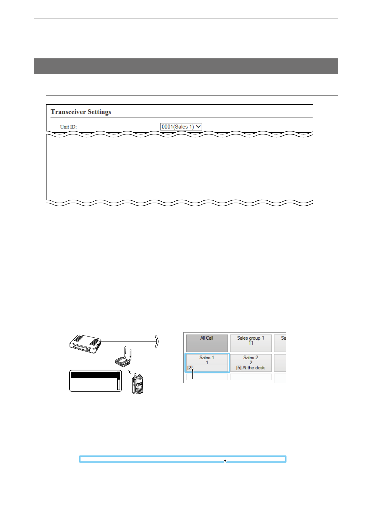
ABOUT THE SETTING SCREEN
IP100FS One-Touch button
4
8. [Transceiver Settings] Menu
[Transceiver Settings]–[Transceiver Settings]
M Transceiver Settings (continued)
!2
!3
!4
!5
!6
!7
(This is only an example.)
!7 Status �������� Select whether the IP100H can send the Status information or not.
(Example: At lunch, Meeting, Waiting) (Default: Disable)
When “Enable” is selected, push [FUNC] on the IP100H twice to enter the
Status selection screen.
• Up to 10 statuses of 32 characters or less can be entered on the [Status]
screen in the [Common Settings] menu.
• The status that the IP100H sends can be displayed on the [Transceiver
Management] screen in the [Transceiver Settings] menu or the one-Touch
button of the IP100FS.
IP100H sends the Status
IP1000C
Wireless
access point
Status
At lunch
Status selection screen
(TX)
IP1000C Transceiver Management screen
IP100H
At lunch
Name, Destination ID, Status number
and Status information
At lunch
Status
4-46
 Loading...