

Page 1

D-STAR REPEATER SYSTEM
id- rp2
Instruction Manual
Page 2

IMPORTANT
READ THIS INSTRUCTION MANUAL
CAREFULLY before attempting to operate the re-
peater.
SAVE THIS INSTRUCTION MANUAL. This
manual contains important safety and operating instructions for the ID-RP2 system.
EXPLICIT DEFINITIONS
WORD DEFINITION
R WARNING
Personal injury, fire hazard or electric
shock may occur.
CAUTION Equipment damage may occur.
NOTE
If disregarded, inconvenience only. No
risk or personal injury, fire or electric
shock.
PRECAUTIONS
R DANGER! ID-RP2 installation, particularly ID-
RP2L and antennas, is intended for professional installation only. We are not responsible for any building
breakage, any damage resulting from a drop of the IDRP2L or antenna from a high place or unstable site or
resulting from any personal injury nor any accident in
any other cases. Be sure to consult an expert engineer
for installations.
R WARNING RF EXPOSURE! This device emits
Radio Frequency
(RF) energy. Extreme caution should
be observed when operating this device. If you have
any questions regarding RF exposure and safety standards please refer to the Federal Communications
Commission Office of Engineering and Technology’s
report on Evaluating Compliance with FCC Guidelines
for Human Radio Frequency Electromagnetic Fields
(OET Bulletin 65)
.
R WARNING HIGH VOLTAGE! NEVER attach an
antenna or internal antenna connector during transmission. This may result in an electrical shock or burn.
R WARNING HIGH VOLTAGE! NEVER install the
antenna at any place that person touch the antenna
easily during transmission. This may result in an electrical shock or burn.
R NEVER apply AC to the [DC 13.8V IN] connector.
This could cause a fire or ruin the repeater.
R NEVER apply more than 16 V DC, such as a 24 V
battery, to the [DC 13.8V IN] connector on the repeater. This could cause a fire or ruin the repeater.
R NEVER let metal, wire or other objects touch any
internal part or connectors on the repeater. This may
result in an electric shock.
R NEVER operate or touch the repeater unit, ID-
RP2C, ID-RP2D and ID-RP2V, with wet hands. This
may result in an electric shock or damage to the repeater unit.
R NEVER expose the repeater unit, ID-RP2C, ID-
RP2D and ID-RP2V, to rain, snow or any liquids.
These units have no water protection.
AVOID using or placing the repeater unit, ID-RP2C,
ID-RP2D and ID-RP2V, in areas with temperatures
below –10°C (+14°F) or above +50°C (+122°F). Be
aware that temperatures can exceed 80°C (+176°F), resulting in permanent damage to the repeater if left
there for extended periods.
AVOID using or placing the ID-RP2L in areas with temperatures below –30°C
(–22°F)
or above +60°C
(+140°F)
. Be aware that temperatures on a vehicle’s
dashboard can exceed 80°C (+176°F), resulting in permanent damage to the repeater if left there for extended periods.
AVOID placing the repeater unit, ID-RP2C, ID-RP2D
and ID-RP2V, in excessively dusty environments or in
direct sunlight.
Place the repeater in a secure place to avoid inadvertent use by children.
DO NOT use chemical agents such as benzine or alcohol when cleaning, as they can damage the repeater’s surfaces.
DO NOT modify the repeater for any reason.
Use the specified fuse only.
For U.S.A. only
CAUTION: Changes or modifications to this repeater,
not expressly approved by Icom Inc., could void your
authority to operate this repeater under FCC regulations.
CAUTION: The ID-RP2L is intended for use as a fixed
base station with the antenna located outdoors on the
rooftop or on antenna tower.
i
Page 3

ii
Icom, Icom Inc. and the logo are registered trademarks
of Icom Incorporated (Japan) in the United States, the United
Kingdom, Germany, France, Spain, Russia and/or other
countries.
Microsoft and Windows are registered trademarks of Microsoft Corporation in the United States and/or other countries.
TABLE OF CONTENTS
IMPORTANT ....................................................................... i
EXPLICIT DEFINITIONS .................................................... i
PRECAUTIONS .................................................................. i
TABLE OF CONTENTS .................................................... ii
1 SYSTEM OUTLINE .................................................. 1– 2
2 SUPPLIED ACCESSORIES ..................................... 3–4
■ Accessories for ID-RP2C ..................................................... 3
■ Accessories for ID-RP2D/ID-RP2V ...................................... 3
■ Accessories for ID-RP2L ...................................................... 3
■ Accessories for AH-106 ........................................................ 4
■ Accessories for AH-107 ........................................................ 4
■ Accessories for AH-108 ........................................................ 4
3 PANEL DESCRIPTIONS .......................................... 5–8
■ ID-RP2C (Front panel) ......................................................... 5
■ ID-RP2C (Rear panel) .......................................................... 5
■ ID-RP2D (Front panel) ......................................................... 6
■ ID-RP2D (Rear panel) .......................................................... 6
■ ID-RP2V (Front panel) ......................................................... 7
■ ID-RP2V (Rear panel) .......................................................... 7
■ ID-RP2L ............................................................................... 8
4 CONNECTIONS AND INSTALLATIONS ............... 9–18
■ Precautions .......................................................................... 9
D About coaxial cable .......................................................... 9
■ About the power supply ........................................................ 9
■ When install into system rack ............................................. 10
■ Rubber feet attachment ...................................................... 10
■ Grounding .......................................................................... 10
■ System connections ........................................................... 11
■ Antenna assembling ........................................................... 12
D AH-106 ........................................................................... 12
D AH-107 ........................................................................... 14
D AH-108 ........................................................................... 16
■ ID-RP2L installation ........................................................... 17
■ Adjusting the parabolic antenna ......................................... 18
D About the test plug ......................................................... 18
D Parabolic antenna beam adjustment .............................. 18
5 DRIVER INSTALLATIONS ................................... 19–33
■ Microsoft®Windows®XP (Service Pack 2) ......................... 19
■ Microsoft®Windows®2000 ................................................. 24
■ Microsoft®Windows®98/Me ............................................... 28
■ COM port confirmation ....................................................... 31
D Microsoft®Windows®XP/2000 ....................................... 31
D Microsoft®Windows®98/Me ........................................... 32
■ USB driver un-installation ................................................... 33
6 UTILITY INSTALLATION ..................................... 34–36
■ Installation .......................................................................... 34
■ Un-installation .................................................................... 36
7 REPEATER SETTINGS ....................................... 37–44
■ ID-RP2C settings ............................................................... 37
D ID-RP2C utility screen .................................................... 38
■ Frequency setting for ID-RP2D .......................................... 41
■ Frequency setting for ID-RP2V .......................................... 42
■ ID-RP2L setting .................................................................. 43
8 MAINTENANCE ................................................... 45–46
■ Troubleshooting .................................................................. 45
■ About cleaning .................................................................... 46
■ Fuse replacement .............................................................. 46
D OPC-1309 ...................................................................... 46
D OPC-1380 ...................................................................... 46
D ID-RP2L’s DC power cable ............................................ 46
9 SPECIFICATIONS AND OPTIONS ...................... 47–48
■ Specifications ..................................................................... 47
D ID-RP2C ......................................................................... 47
D ID-RP2L ......................................................................... 47
D ID-RP2D/ID-RP2V .......................................................... 48
■ Options ............................................................................... 48
Page 4

1
SYSTEM OUTLINE
1
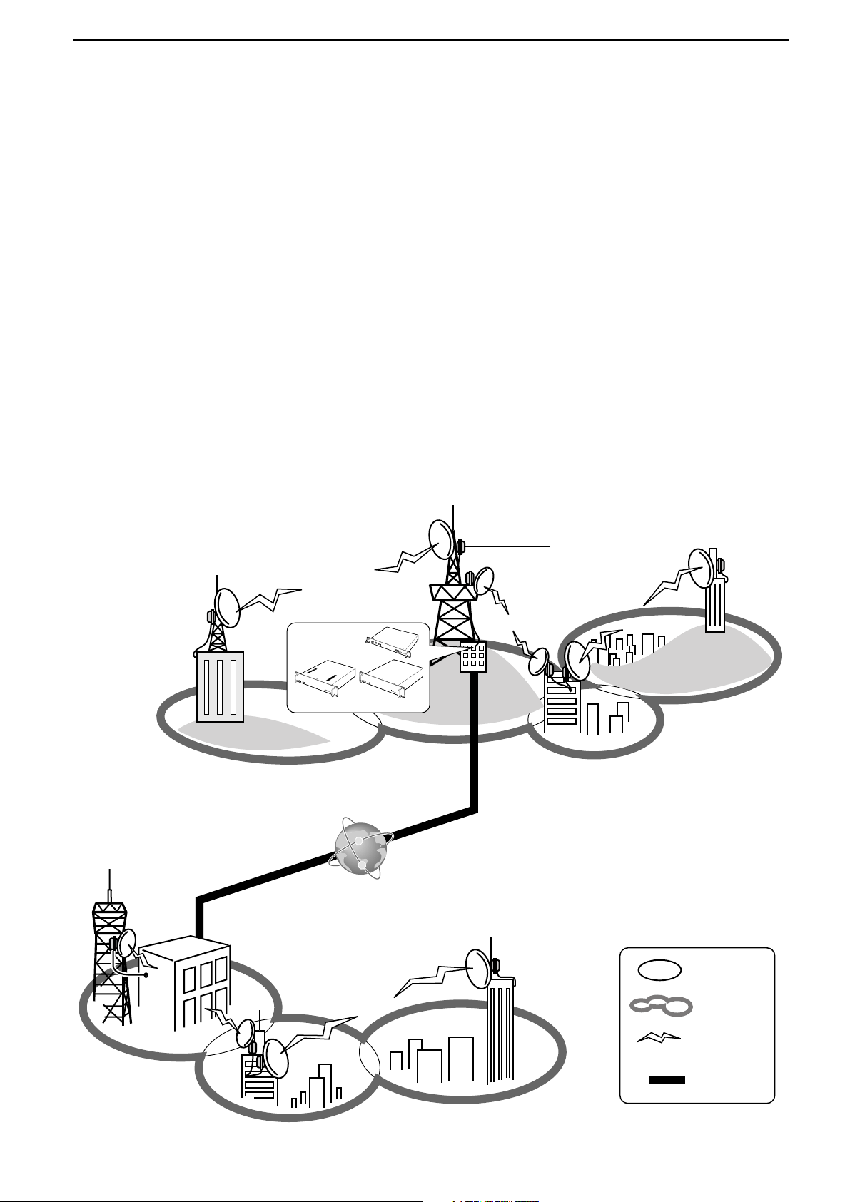
The D-star repeater site can be constructed by combining with the following units according to the plan or
scale.
ID-RP2C : Repeater controller
ID-RP2D : 1.2 GHz data repeater
ID-RP2V : 1.2 GHz digital voice repeater
ID-RP2L : 10 GHz microwave link repeater
In addition, the following options are also required for
system repeater operations.
AH-106 : 10 GHz Parabolic antenna 800 (d)
AH-107 : 10 GHz Parabolic antenna 450 (d)
AH-108 : 1.2 GHz Collinear antenna
■ ID-RP2C
➥The ID-RP2C is a repeater controller and one con-
troller should be used in each repeater site.
The controller relays digital voice or data (traffic) sig-
nals for repeater operation.
➥Total 4 interface connectors for local repeater con-
nections are available.
Both digital voice and data repeaters can be connected as desired.
• Standard composition:
Data repeater 1
Digital voice repeater 1
Spares 2 (for another band’s repeater)
NOTE: Connect only 1 or 2 repeaters for the
same frequency band is recommended
to avoid interference.
➥Total 2 interface connectors for microwave link re-
peater connections are available.
Microwave link repeater can be connected as desired.
➥One Ethernet port
(10Base-T) is available for re-
peater site call sign, IP address settings etc., from
the PC and the ID-RP2C utility software.
Or, a gateway control PC can be connected as desired.
➥By connecting the ID-RP2L utility installed PC, op-
erating frequency set and operation monitor can be
made.
■ ID-RP2D
➥ID-RP2D is a 1.2 GHz data (128 kbps) repeater and
connects to the ID-RP2C.
*The ID-RP2D never functions as a repeater without ID-
RP2C, due to no relay function is built-in.
➥The ID-RP2D/V utility software, supplied with the ID-
RP2C, and a PC are required for both receive and
transmit frequency settings.
➥Repeater operation is performed in simplex mode on
the same frequency for data mode, however, different frequencies between transmit and receive can
be set in simplex mode.
■ ID-RP2V
➥ID-RP2V is a 1.2 GHz digital voice and slow-speed
data repeater (4.8 kbps) and connects to the IDRP2C.
*The ID-RP2V never functions as a repeater without ID-
RP2C, due to no relay function is built-in.
NOTE: No audio CODEC is performed in the ID-
RP2V, thus the ID-RP2V receives and
transmits 4.8 kbps serial data only.
➥Different frequencies are used for each transmission
and reception in semi-duplex mode.
➥The ID-RP2D/V utility software, supplied with the ID-
RP2C, and a PC are required for both receive and
transmit frequency settings.
■ ID-RP2L
➥ID-RP2L is a 10 GHz microwave link repeater (10
Mbps)
and connects to the ID-RP2C. The microwave
link repeater provides to linking with another repeater site (Area) for zone construction.
➥Different frequencies are used for each transmission
and reception in full-duplex mode and the reversed
frequencies between transmit and receive are used
for the oncoming repeater.
➥The received GMSK serial bit-stream signal (10
Mbps)
is applied to either ID-RP2D or ID-RP2V via
the ID-RP2C. Then the GMSK serial data is transmitted to the local station.
➥The ID-RP2L has a duplexer, and the condition of
the microwave link repeater can be monitored when
the ID-RP2L utility software (supplied with the ID-
RP2C)
installed PC is connected to the ID-RP2C.
Page 5
2
1
SYSTEM OUTLINE
DD
AH-106 : 10 GHz parabolic antenna 800 (d)
DD
AH-107 : 10 GHz parabolic antenna 450 (d)
➥Both AH-106 and AH-107 are offset parabolic an-
tenna and connect to ID-RP2L.
Up to 20 km (approx.; 12.4 miles)* or 8 km (approx.;
5 miles)
* of communication range is provided when
AH-106 or AH-107 is used at the both microwave
link repeaters, respectively.
And up to 12 km (approx.; 7.5 miles)* of communication range is provided between AH-107 and AH106’s repeaters.
*Communication range may differ/change according to en-
vironment, such as weather, installed conditions, etc.
DD
AH-108 : 1.2 GHz Collinear antenna
➥2 Collinear antennas are built-in and better isolation
is provided than separated 2 antennas.
Zone
Area
Signal
Internet
Antenna
ID-RP2L
D
-
S
T
A
R
P
O
W
E
R
10
B
E
S
E
-T
S
E
R
V
IC
E
1
S
E
R
V
I
C
E
2
A
S
S
I
S
T
1
A
S
S
I
S
T
2
ID
R
P
2C
R
e
p
e
a
t
e
r
C
o
n
t
r
o
l
l
e
r
D
-
S
T
A
R
S
E
R
V
I
C
E
P
O
W
E
R
I
D
R
P
2
D
R
e
p
e
a
t
e
r
C
o
n
t
r
o
l
l
e
r
L
/
H
D
-
S
T
A
R
SE
RV
ICE
T
SE
RV
IC
E R
P
O
W
E
R
I
D
R
P
2
V
R
e
p
e
a
t
e
r
C
o
n
t
r
o
l
l
e
r
ID-RP2C
ID-RP2V
ID-RP2D
InternetInternet
Page 6
2
3
SUPPLIED ACCESSORIES
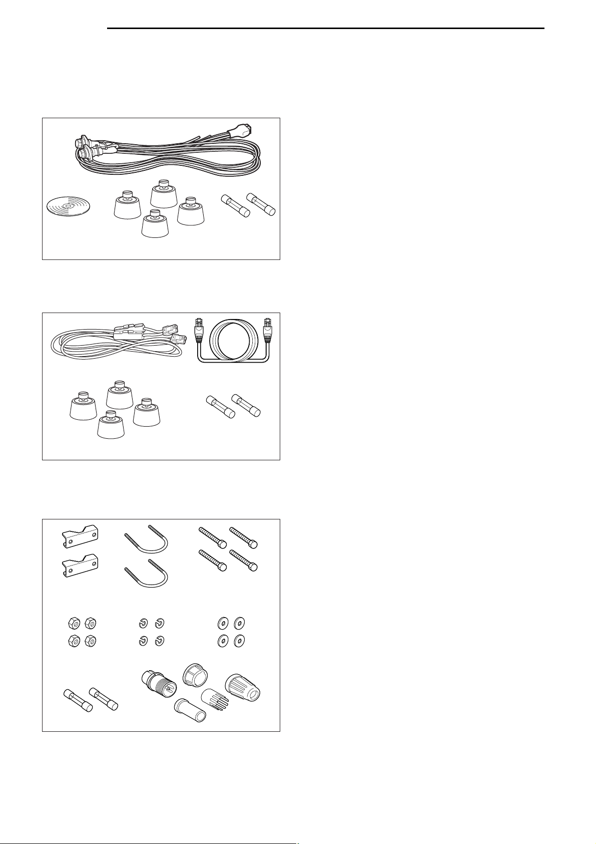
■ Accessories for ID-RP2C
q Power cable (OPC-1380; approx. 3 m; 10 ft) ……… 1
w Utility CD …………………………………………… 1
e Rubber feet ………………………………………… 4
r Spare fuses (FGB01 30A) ………………………… 2
■ Accessories for ID-RP2D/ID-RP2V
q Power cable (OPC- 1309; approx. 1 m; 3.3 ft) …… 1
w Control cable (OPC-1069) ………………………… 1
e Rubber feet ………………………………………… 4
r Spare fuses (FGB10A) …………………………… 2
■ Accessories for ID-RP2L
q Pole clamps ………………………………………… 2
w U-bolts ……………………………………………… 2
e Bolts (M6×50) ……………………………………… 4
r Nuts (M6) …………………………………………… 4
t Spring washers (M6) ……………………………… 4
y Flat washers (M6) ………………………………… 4
u Spare fuses (FGB5A) ……………………………… 2
i Test plug ……………………………………… 1 set
q
w
rt y
e
ui
q
w
e
r
q
w
r
e
Page 7
4
2
SUPPLIED ACCESSORIES
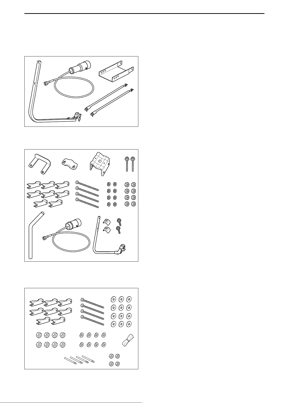
■ Accessories for AH-106
q Element arm ……………………………………… 1
w Element …………………………………………… 1
e Elevation support plate …………………………… 1
r Support arms ……………………………………… 2
■ Accessories for AH-107
q Pole stopper ……………………………………… 1
w Pole clamp ………………………………………… 1
e Clamp base (w/bolts) ………………………… 1 set
r Bolts (M6×65) ……………………………………… 2
t Pole clamps ………………………………………… 8
y Bolts (M8×170) ……………………………………… 4
u Spring washers (M8) ……………………………… 8
i Nuts (M8) …………………………………………… 8
o Pole ………………………………………………… 1
!0 Element …………………………………………… 1
!1 Element arm ……………………………………… 1
!2 Element arm holders ……………………………… 2
!3 Bolts (M6×30) ……………………………………… 2
■ Accessories for AH-108
q Pole clamps ……………………………………… 8
w Bolts (M8×160) ……………………………………… 4
e Flat washers (M8) ………………………………… 12
r Nuts (M8) …………………………………………… 8
t Spring washers (M8) ……………………………… 8
y Rubber vulcanizing tape (approx. 60 cm; 2 ft) …… 1
u Radials ……………………………………………… 4
i Nuts (M6) …………………………………………… 4
qwe
rt
y
ui
qw e
r
qw
ty
er
ui
!2 !3
o!0 !1
Page 8
3
5
PANEL DESCRIPTIONS
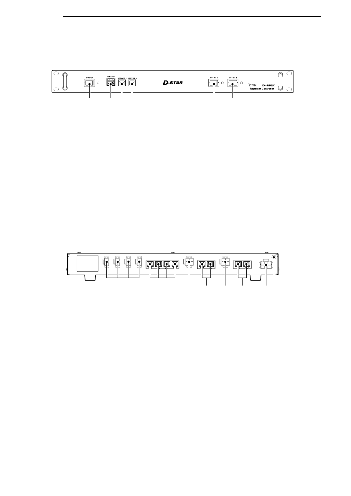
■ ID-RP2C (Front panel)
q POWER SWITCH [POWER]
The power switch for ID-RP2C.
The LED indicator located at right lights when the
power is turned ON.
w 10BASE-T CONNECTOR [10BASE-T] (p. 37)
Connects a PC via LAN cable (purchase separately)
to set the details of the repeater site, such as the
call sign, IP address.
A Gateway server can also be connected to this
connector.
e SERVICE 1 CONNECTOR (p. 43)
Connects a PC via an USB cable
(A-B type; purchase
separately)
to set the operating frequency or monitor
the repeater operation for the microwave link repeater that is connected to [ASSIST1] connector.
r SERVICE 2 CONNECTOR (p. 43)
Connects a PC via an USB cable
(A-B type; purchase
separately)
to set the operating frequency or monitor
the repeater operation for the microwave link repeater that is connected to [ASSIST2] connector.
t ASSIST 1 SWITCH
Turns the microwave link repeater power ON and
OFF, that is connected to [ASSIST1] connector.
The LED indicator located at right lights when the
power is turned ON.
y ASSIST 2 SWITCH
Turns the microwave link repeater power ON and
OFF, that is connected to [ASSIST2] connector.
The LED indicator located at right lights when the
power is turned ON.
qwer ty
■ ID-RP2C
(Rear panel)
q POWER CONNECTORS
[LOCAL RPT— DC13.8V OUT] (p. 11)
Outputs 13.8 V DC for local repeater.
Connects ID-RP2D/V via the supplied DC power
cable (OPC-1309; supplied with the ID-RP2D/V).
The same voltage as the supplied voltage to
[DC13.8V IN] connector is output regardless of the
[POWER] switch condition on the front panel.
w [LOCAL RPT— CONT I/O] (p. 11)
Input/output ports for local repeater to received or
transmitted serial data routing.
Connects ID-RP2D/V via the supplied control cable
(supplied with the ID-RP2D/V).
e DC POWER CONNECTOR
[ASSIST 1— DC 13.8V OUT]
Connects ID-RP2L’s power cable.
The DC power is turned ON and OFF with [ASSIST
1] switch on the front panel.
r ASSIST 1— A/B (p. 11)
Connects ID-RP2L’s data cable.
Connects data cable connector [A] to left and data
cable connector [B] to right connector.
t DC POWER CONNECTOR
[ASSIST 2— DC 13.8V OUT]
Connects ID-RP2L’s power cable.
The DC power is turned ON and OFF with [ASSIST
2] switch on the front panel.
y ASSIST 2— A/B (p. 11)
Connects ID-RP2L’s data cable.
Connects data cable connector [A] to left and data
cable connector [B] to right connector.
u POWER CONNECTOR [DC 13.8V IN] (p. 11)
DC power input connector for ID-RP2 system.
Connects a 13.8 V DC power supply unit via the DC
power cable (OPC-1380; supplied with the ID-RP2C).
i GROUND TERMINAL [GND] (p. 10)
Connects to a ground to prevent electrical shocks,
TVI, BCI and other problems.
qwe ut ir y
Page 9
6
3
PANEL DESCRIPTIONS
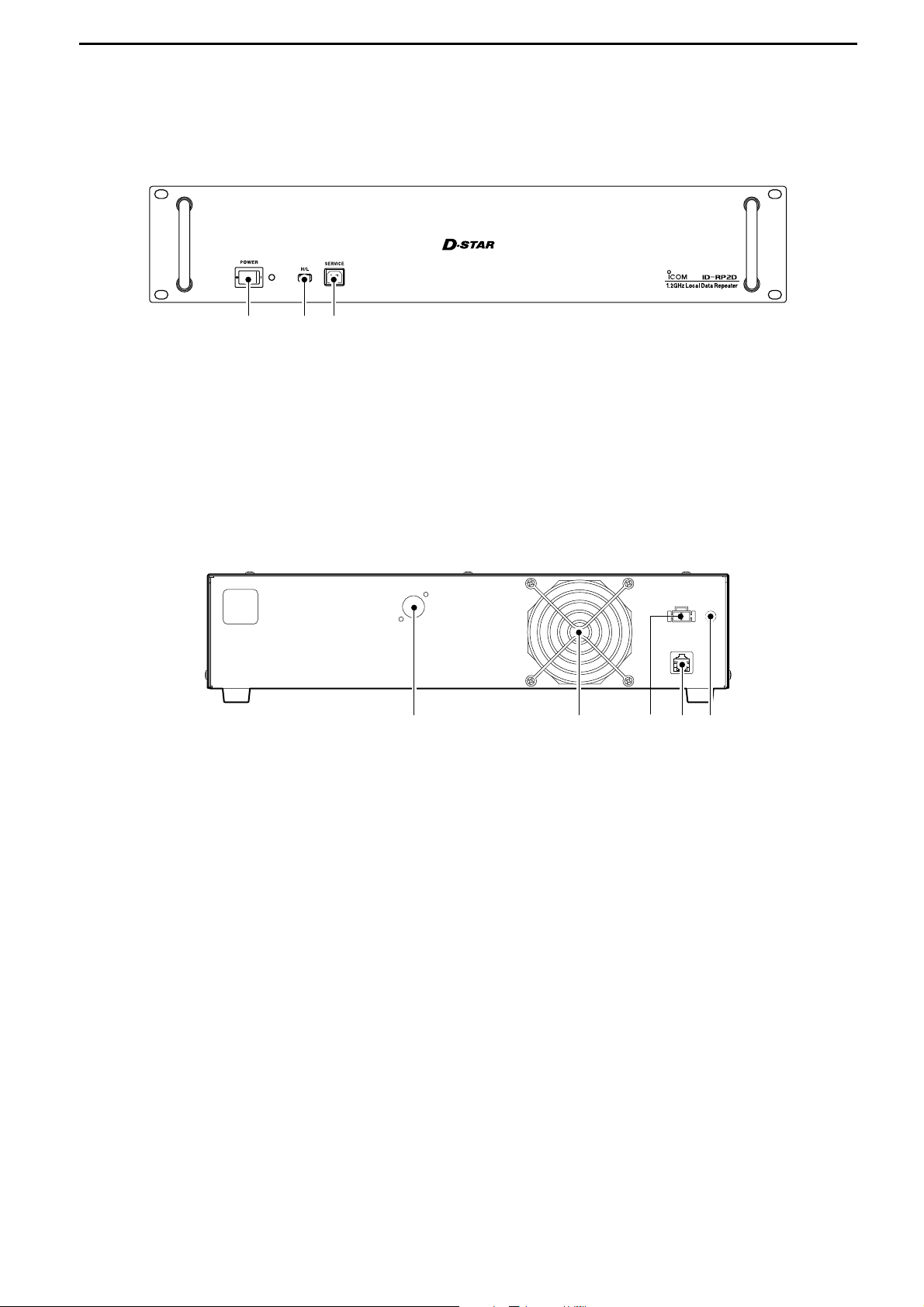
■ ID-RP2D (Front panel)
q POWER SWITCH [POWER]
The power switch for ID-RP2D.
The LED indicator located at right lights when the
power is turned ON.
w HIGH/LOW POWER SELECT SWITCH [H/L]
Selects the transmit output power High (approx.
10 W)
and Low (approx. 1 W).
e SERVICE CONNECTOR [SERVICE] (p. 41)
Connects a PC via an USB cable (A-B type; purchase
separately)
to set the both transmit and receive fre-
quencies.
qwe
■ ID-RP2D (Rear panel)
q ANTENNA CONNECTOR [ANT] (p. 11)
Connect the optional AH-108 1.2 GHz Collinear antenna.
When both ID-RP2D and ID-RP2V is composed in
a site, an antenna filter, such as bandpass filter, resonator, or so, should be installed between the IDRP2D and antenna to protect the ID-RP2D reception from interference of the ID-RP2V downlink
signal.
w COOLING FAN
e POWER CONNECTOR [DC13.8V] (p. 11)
Connects to ID-RP2C via the supplied DC power
cable (OPC-1309) to be supplied the DC power.
r [CONT I/O] (p. 11)
Connects to ID-RP2C via the supplied control cable
for received or transmitted serial data communication.
t GROUND TERMINAL [GND] (p. 10)
Connects to a ground to prevent electrical shocks,
TVI, BCI and other problems.
qwer t
Page 10
7
3
PANEL DESCRIPTIONS
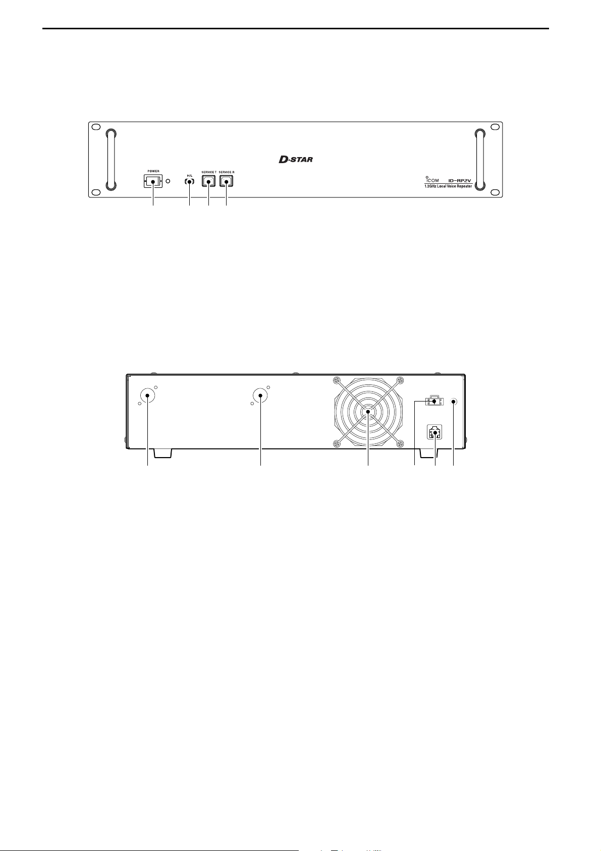
■ ID-RP2V (Front panel)
q POWER SWITCH [POWER]
The power switch for ID-RP2V.
The LED indicator located at right lights when the
power is turned ON.
w HIGH/LOW POWER SELECT SWITCH [H/L]
Selects the transmit output power High (approx.
10 W)
and Low (approx. 1 W).
e SERVICE CONNECTOR T [SERVICE T] (p. 42)
Connects a PC via an USB cable (A-B type; purchase
separately)
to set the transmit frequency.
r SERVICE CONNECTOR R [SERVICE R] (p. 42)
Connects a PC via an USB cable (A-B type; purchase
separately)
to set the receive frequency.
qwer
■ ID-RP2V (Rear panel)
q RECEIVE ANTENNA CONNECTOR [ANT] (p. 11)
Connect the optional AH-108 1.2 GHz Collinear antenna through a duplexer.
w
TRANSMIT ANTENNA CONNECTOR [ANT] (p. 11)
Connect the optional AH-108 1.2 GHz Collinear antenna through a duplexer.
e COOLING FAN
r POWER CONNECTOR [DC13.8V] (p. 11)
Connects to ID-RP2C via the supplied DC power
cable (OPC-1309) to be supplied the DC power.
t [CONT I/O] (p. 11)
Connects to ID-RP2C via the supplied control cable
for received or transmitted serial data communication.
y GROUND TERMINAL [GND] (p. 10)
Connects to a ground to prevent electrical shocks,
TVI, BCI and other problems.
qerw t y
Page 11
8
3
PANEL DESCRIPTIONS
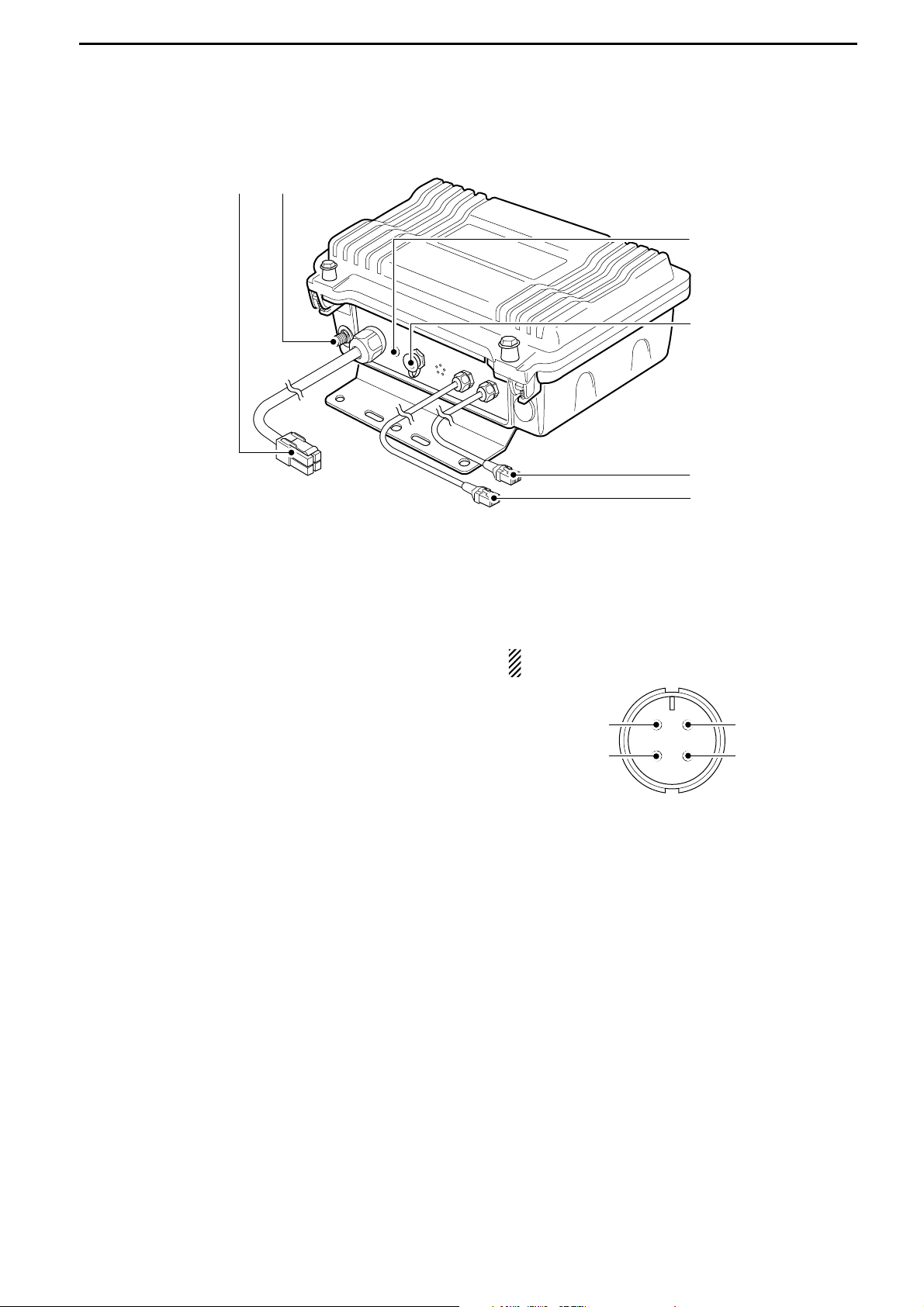
■ ID-RP2L
q POWER CABLE CONNECTOR [DC13.8V] (p. 11)
Connects to ID-RP2C to be supplied the DC power.
Cable length: Approx. 30 m; 100 ft
w ANTENNA CONNECTOR [ANT] (p. 11)
Connects an optional parabolic antenna AH-106 or
AH-107.
e STATUS INDICATOR [STATUS]
Indicates the following unit conditions.
• Light : The power is ON and functioning correctly.
•
Flashing slowly
: Unlock PLL (Reboot the ID-RP2L.
If the indicator still flashing even
after rebooting, contact authorized
Icom dealer or distributor.)
• Flashing fast : Setting data malfunction.
(Data initializing and re-setting are
required using with the ID-RP2L
utility software.)
• Light off : The power is OFF.
r TEST PLUG [TEST] (p. 18)
Connects the supplied test plug* when adjusting the
parabolic antenna beam.
Test mode is automatically selected when connecting the test plug.
IMPORTANT!: Attach the waterproof cap during
normal operation.
*See p. 18 for test plug assembling and connections de-
tails.
t DATA CABLE CONNECTOR B [DATA B] (p. 11)
Connects to the ID-RP2C for transmit/receive signal data and control signal communications.
Cable length: Approx. 30 m; 100 ft
y DATA CABLE CONNECTOR A [DATA A] (p. 11)
Connects to the ID-RP2C for transmit/receive signal data and control signal communications.
Cable length: Approx. 30 m; 100 ft
q RSSI output
w TEST
e GND
r GND
Front view
qw
e
r
t
y
Page 12
4
9
CONNECTIONS AND INSTALLATIONS
■ Precautions
NEVER expose the ID-RP2C/D/V to rain, snow or any
liquids.
NEVER connect the repeater to a power source using
reverse polarity. This will damage the repeater.
And turn the repeater power OFF when connecting a
power supply.
AVOID using or placing the ID-RP2C/D/V in areas with
temperature below –10˚C (+14˚F) or above +50˚C
(+122˚F).
AVOID placing the ID-RP2C/D/V in excessively dusty
environments or in direct sunlight.
AVOID placing the ID-RP2C/D/V against walls or
putting anything on top of the units. This will obstruct
heat dissipation.
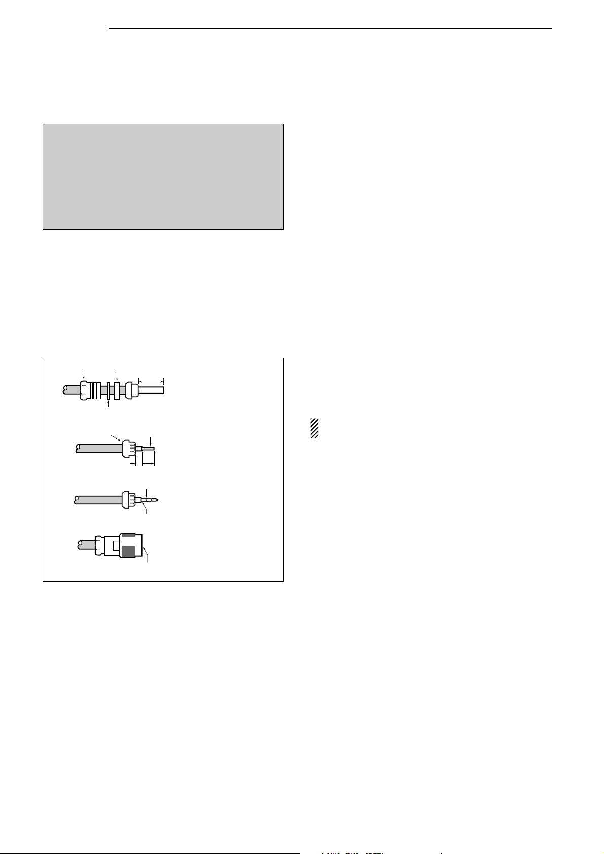
DD
About coaxial cable
• Type-N connector assembling
Use 50 Ω of impedance for both antenna (at Feeding
power point)
and coaxial cable.
Type-N connector is used for the connection between
ID-RP2D/V and antenna.
RECOMMENDATION: Install a lightning protector
between the ID-RP2D/V and antenna.
■ About the power supply
Be sure to the DC power supply that used with the IDRP2 system is meet the followings:
Output voltage : 13.8 V DC ±15%
Current capacity : At least the total current consump-
tion of the connected equipments.
Slide the nut, washer,
rubber gasket and clamp
over the coaxial cable,
then cut the end of the
cable evenly.
Strip the cable and fold the
braid back over the clamp.
Soft solder the center
conductor. Install the
center conductor pin and
solder it.
Carefully slide the plug
body into place aligning the
center conductor pin on the
cable. Tighten the nut onto
the plug body.
q
w
e
r
15 mm
3 mm
6 mm
No space
Solder hole
Be sure the center conductor is
the same height as the plug body.
Clamp
Center
conductor
Washer
Nut Rubber gasket
R DANGER! ID-RP2 installation, particularly ID-
RP2L and antennas, is intended for professional installation only. We are not responsible for any
building breakage, any damage resulting from a drop
of the ID-RP2L or antenna from a high place or unstable site or resulting from any personal injury nor
any accident in any other cases. Be sure to consult
an expert engineer for installations.
Page 13
10
4
CONNECTIONS AND INSTALLATIONS
■ When install into system rack
The ID-RP2C/D/V are designed to install into the 19inch rack (EIA standard) directly.
Use the supplied bolts with the rack when fixing the IDRP2C/D/V.
We recommend to use the rack that has rails due to
the weigh of the ID-RP2D and ID-RP2V is approx.
6.2 kg
(13.7 lbs) and approx. 7.5 kg (16.5 lbs), respec-
tively.
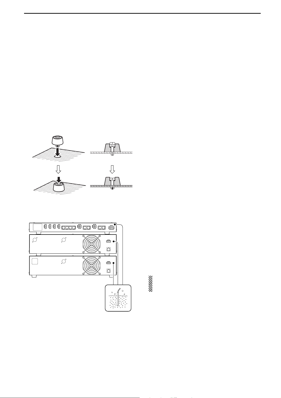
■ Rubber feet attachment
Attach the supplied rubber feet onto the bottom of the
ID-RP2C/D/V as shown at left when not installed into
19-inch rack. Desktop operation can be performed.
■ Grounding
To prevent electrical shock, television interference
(TVI), broadcast interference (BCI) and other problems,
ground the transceiver through the GROUND terminal
on the rear panel.
For best results, connect a heavy gauge wire or strap
to a long earth-sunk copper rod.
Make the distance between the [GND] terminal and
ground as short as possible.
R WARNING: NEVER connect the [GND] ter-
minal to a gas or electric pipe, since the connection
could cause an explosion or electric shock.
q • Cross section
w
Page 14
11
4
CONNECTIONS AND INSTALLATIONS
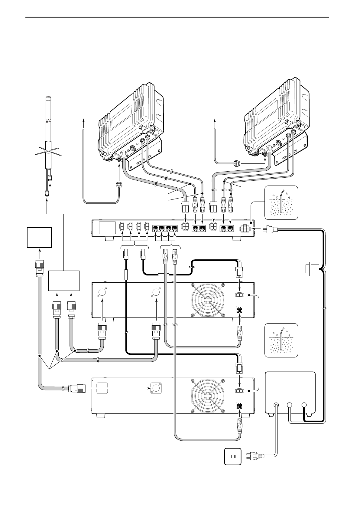
■ System connections
Antenna
filter
Duplexer
ID-RP2V
Coaxial cables
(purchase locally)
ID-RP2D
ID-RP2C
[A]
[B]
[B]
[A]
OPC-1380
(supplied w/ID-RP2C)
to AH-106/107to AH-106/107
OPC-1309
(supplied w/ID-RP2D/V)
OPC-1309
(supplied w/ID-RP2D/V)
Control cable
(supplied w/ID-RP2D/V)
Control cable
(supplied w/ID-RP2D/V)
ID-RP2L
(Assist 1)
AH-108
ID-RP2L
(Assist 2)
AC outlet
AC power cable
External DC power
supply 13.8 V
Black
_
Red
+
Page 15
12
4
CONNECTIONS AND INSTALLATIONS
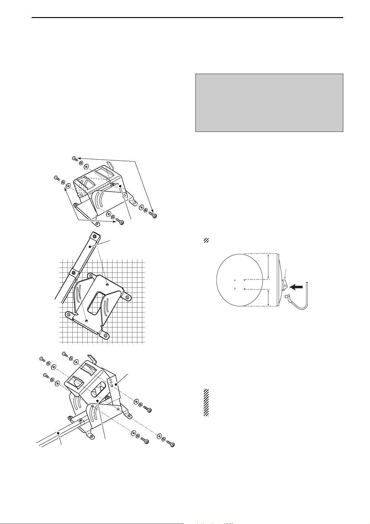
■ Antenna assembling
DD
AH-106
q Remove the pole clamp that attached to the eleva-
tion angle.
w Unscrew 4 bolts from the elevation angle.
e Attach the element-arm onto the reflector.
NOTE: Check the orientation.
r Attach the elevation and sub elevation angles as
the diagram at left.
Fix the angles using with the bolts that are un-
screwed at steps w and are attached with the sub
elevation angle.
NOTE: Select the suitable screw hole position
that the point where the suitable parabolic antenna beams angle is provided with the sub elevation angle adjustment.
☞
Continue to the next page.
Sub elevation
angle
Elevation angle
Element arm
Top Reflector
Reflector
Elevation
base angle
Elementarm
LongShort
Bottom
Element arm
Unscrew
Unscrew
Elevation angle
R DANGER!: Antenna installation is intended for
professional installation only. We are not responsible
for any building breakage, any damage resulting
from a drop of the antenna from a high place or unstable site or resulting from any personal injury nor
any accident in any other cases. Be sure to consult
an expert engineer for installations.
Page 16
13
4
CONNECTIONS AND INSTALLATIONS
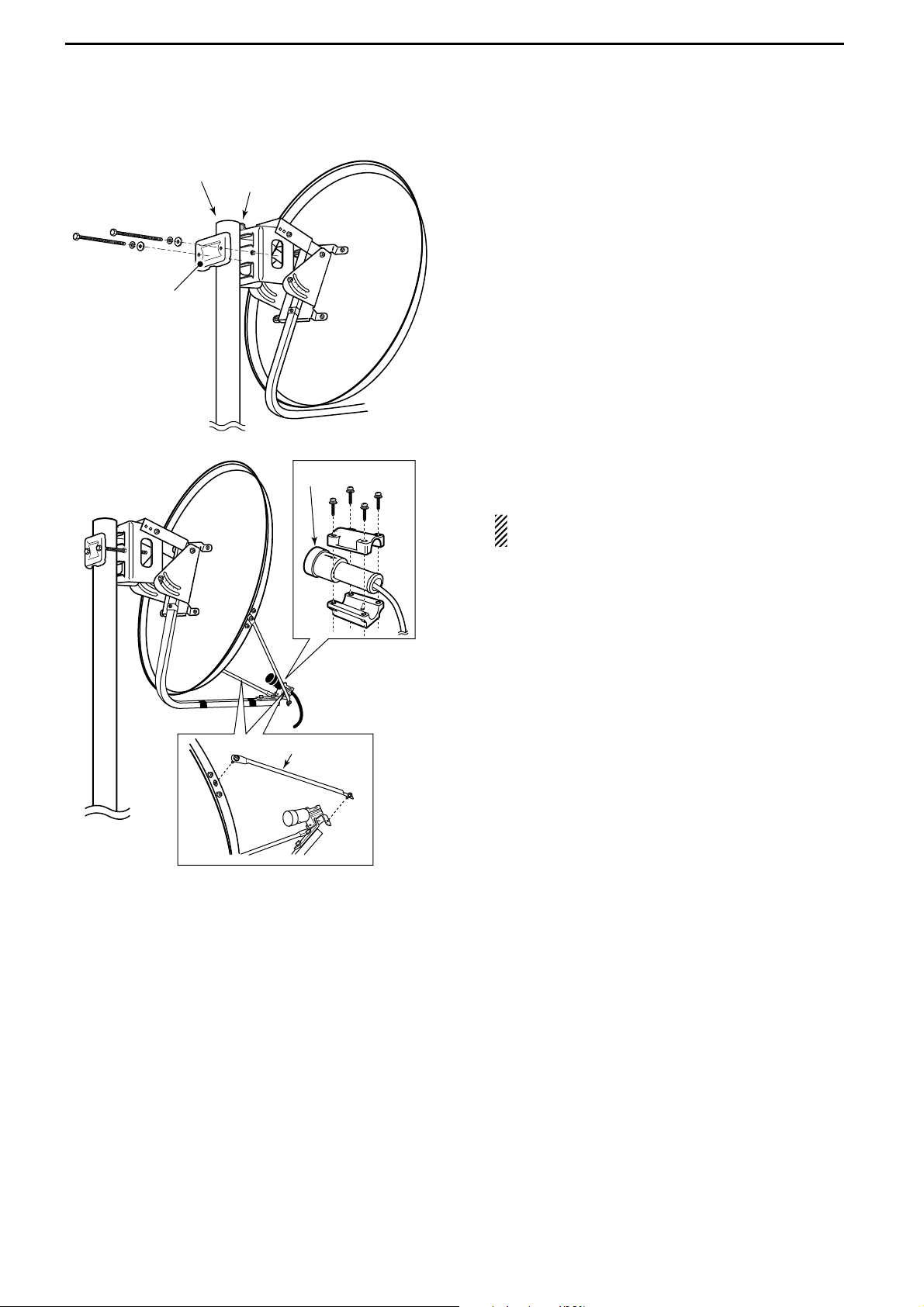
t Attach the pole between the elevation angle and the
pole clamp, that is removed in steps q, as illustrated at left.
• Tighten the two bolts within an even torque.
• Use the stopper of the elevation angle when installing
the antenna at the top edge of the pole.
y Attach the supplementary arms between element
arm and parabolic reflector, and attach the antenna
element to the element arm.
NOTE: The “V” stamps on the antenna element
must be face up.
Supplementary
arm
Element
Pole
(48.6–89.1 mm)
Pole clamp
Stopper
Page 17

14
4
CONNECTIONS AND INSTALLATIONS
DD
AH-107
q Attach the element arm to the parabolic reflector
using with the supplied bolts (M6×30) and the element arm fitting plates.
Note: Check the orientation.
w Attach the clamp base.
Use the bolts that are attached to the clamp base.
e Attach the pole stopper with the supplied bolts
(M6×65) temporary.
☞
Continue to the next page.
Pole stopper
Bolts
(M6×65)
Bolts
(Attached at the
clamp base)
Clamp base
Top Reflector
Reflector
Elevation
base angle
Elementarm
LongShort
Bottom
Bolts
M6×30
Element-arm
fitting plate
Elementarm
Page 18

15
4
CONNECTIONS AND INSTALLATIONS
r Fix the supplied pole with the pole clamp as illus-
trated at left.
t Attach the antenna element to the element holder.
NOTE: The “Z” stamps on the antenna element
must be face up.
y Install the assembled parabolic antenna to the pole.
IMPORTANT!
Make fast the parabolic antenna to the pole with the
wire (purchase locally) through the ring in the upper
behind of the reflector to prevent the parabolic antenna dispersion or the fall.
Pole clamp
Pole
(32–60mm)
Bolts (M8)
Pole clamp
Spring
washer (M8)
Nut
(M8)
Element
Check the
orientation
Element
holder
Pole (Supplied item)
Pole stopper
Pole clamp
Page 19

16
4
CONNECTIONS AND INSTALLATIONS
DD
AH-108
q Attach the nut (M6) to the radial, then attach the ra-
dial to the AH-108.
w Attach the supplied bolts, pole clamps, spring wash-
ers, flat washers and nuts to the AH-108 as illustrated at left.
CAUTION!: The pole clamps must be attached
to the plating area only. Attachment to other part
may cause damage of the AH-108 due to
strength shortage.
e Fix the AH-108 to the pole using with the supplied
pole clamps, spring washers, flat washers and nuts.
Pole
(30–60 mm)
Spring washer
Flat washer
Nut
Plating area
Nut Radial
AH-108
Pole clamps
Pole clamps
AH-108
Page 20

17
4
CONNECTIONS AND INSTALLATIONS
■ ID-RP2L installation
ID-RP2L must be connected to the parabolic antenna
element directly.
The element cable extension may cause communication error, therefore the ID-RP2L must be installed right
under the parabolic antenna.
q Install the ID-RP2L onto the pole, right under the
parabolic antenna, using with the supplied U-bolts,
pole clamps, flat washers, spring washers and nuts.
NOTE: The ID-RP2L must be installed where the
place without obstacle to the parabolic antenna
beam adjustment.
w Connect the antenna element to the ID-RP2L [ANT]
connector.
e Fix the antenna element cable to the element arm
with slacks for both element and ID-RP2L sides
using with vinyl tape or cable fastener, etc.
NOTE: Cover the antenna connector with rubber
vulcanizing tape to protect the antenna connector
from water intrusion.
*Wrap the rubber vulcanizing tape from the under on.
Rubber vulcanizing
tape
(purchase locally)
*Wrap from under on.
Fix with an adhesive tape
U-bolt
Pole clamp
Flat washer
Spring
washer
Nut
ID-RP2L
R DANGER!: The ID-RP2L installation is in-
tended for professional installation only. We are not
responsible for any building breakage, any damage
resulting from a drop of the ID-RP2L from a high
place or unstable site or resulting from any personal
injury nor any accident in any other cases. Be sure to
consult an expert engineer for installations.
Page 21

18
4
CONNECTIONS AND INSTALLATIONS
■ Adjusting the parabolic antenna
DD
About the test plug
Assemble the test plug before adjusting the parabolic
antenna as follows.
q Shorten the TEST
(pin 2) and GND (pin 3) terminals
of the test plug, that supplied with the ID-RP2L.
w Connects a wire to each the RSSI
(pin 1)
and GND
(pin 4) to be connected to a voltmeter.
e Assemble the test plug as illustrated at left.
DD
Parabolic antenna beam adjustment
Adjust the parabolic antenna beam as the following instruction.
Due to very critical adjustment is required, attend 2 or
more persons for adjustment.
q Turn the parabolic antenna beam to the opposed
microwave link repeater, and fix it temporarily.
w Connects a voltmeter to [TEST] connector of the ID-
RP2L through the test plug.
• Transmits a test signal automatically.
• Transmits a test signal from the opposed microwave link
repeater also.
•The voltmeter swings when the test signal is received
from the opposed microwave link repeater.
e Adjust the parabolic antenna beam direction and el-
evation angles to the point where the voltmeter
shows maximum voltage, then fix the antenna.
Adjust the beam (direction)
after loosen the bolts.
Adjust the beam (elevation)
after loosen the bolts.
Voltmeter
to + (voltmeter)
q
we
r
+
Shorten
to _ (voltmeter)
_
Page 22

5
19
DRIVER INSTALLATIONS
The USB (Universal Serial Bus) cable (A-B type; purchase
separately)
is used for the connection between ID-RP2
and a PC.
So, the USB driver installation is required for the PC.
In addition, individual USB driver installation is required
for each connector and unit, because the communication port number difference.
In this instruction, describes with the installation of the
ID-RP2C [SERVICE1] connector for example.
■ Microsoft®Windows®XP (Service Pack 2)
q Start up the Windows.
• Quit all applications if activated.
w Insert the CD that comes with the ID-RP2C, into the
CD drive.
e Connect the PC and ID-RP2C [SERVICE1] con-
nector using with an USB cable
(A-B type; purchase
separately)
.
r “Found New Hardware ID-RP2C SERVICE 1” ap-
pears as at left.
t The “Found New Hardware Wizard” will come up as
at left.
Select “No, not this time” then click [Next>].
Click
Select
NOTE:
The repeater unit connection may not be recognized
with the PC according to the using USB cable length.
Use the shorter USB cable as possible is recommended.
IMPORTANT!
A different USB driver from the ID-1 is used for the
ID-RP2 system.
Uninstall the USB driver for ID-1 first, then install the
USB driver for ID-RP2 system if the USB driver for
ID-1 is installed in the PC.
Page 23

20
5
DRIVER INSTALLATIONS
y Insert the supplied CD into the CD drive, select “In-
stall the software automatically (Recommended),”
then click [Next>].
u The wizard starts searching for the driver and
shows the dialog as at left during search.
i While searching the driver, the “Hardware Installa-
tion” dialog box appears as at left.
Click [Continue Anyway] to start the installation.
NOTE: If the dialog as at left does not appear,
select “Install from a list or specific location (Advanced)” in step y, then select the driver folder
in the CD.
☞
Continue to the next page.
Click
Click
Select
Page 24

21
5
DRIVER INSTALLATIONS
■ Microsoft®Windows®XP (Service Pack 2)— continued
o Windows starts installing the USB driver.
!0 After the installation is completed, click [Finish].
!1 After clicking [Finish], “Found New Hardware USB
Serial Port” appears as at left.
!2 The “Found New Hardware Wizard” will come up as
at left.
Select “No, not this time” then click [Next>].
Click
Select
Click
Page 25

22
5
DRIVER INSTALLATIONS
!3 Insert the supplied CD into the CD drive, select “In-
stall the software automatically (Recommended),”
then click [Next>].
!4 The wizard starts searching for the driver and
shows the dialog as at left during search.
!5 While searching the driver, the “Hardware Installa-
tion” dialog box appears as at left.
Click [Continue Anyway] to start the installation.
NOTE: If the dialog as at left does not appear,
select “Install from a list or specific location (Advanced)” in step !3, then select the driver folder
in the CD.
☞
Continue to the next page.
Click
Click
Select
Page 26

23
5
DRIVER INSTALLATIONS
■ Microsoft®Windows®XP (Service Pack 2)— continued
!6 Windows starts installing the USB driver.
!7 After the installation is completed, click [Finish].
!8 After clicking [Finish], “Found New Hardware Your
new hardware is installed and ready to use” appears as at left.
!9 Eject the CD.
• Rebooting the PC is recommended.
Click
Page 27

24
5
DRIVER INSTALLATIONS
■ Microsoft®Windows®2000
q Start up the Windows.
• Quit all applications if activated.
w Insert the CD that comes with the ID-RP2C, into the
CD drive.
e Connect the PC and ID-RP2C [SERVICE1] con-
nector using with an USB cable (A-B type; purchase
separately)
.
r “Found New Hardware ID-RP2C SERVICE 1” ap-
pears as at left.
t The “Found New Hardware Wizard” will come up as
at left.
Click [N
ext >].
y Insert the supplied CD into the CD drive, select
“S
earch for a suitable driver for my device (recom-
mended),” then click [Next>].
☞
Continue to the next page.
Click
Select
Click
Page 28

25
5
DRIVER INSTALLATIONS
■ Microsoft®Windows®2000— continued
u Select “C
D-ROM drives,” then click [N
ext >].
i When the appropriate driver is found, the dialog box
appears as at left appears.
Click [N
ext >] to start the installation.
o After the installation is completed, click [Finish].
!0 After clicking [Finish], “Found New Hardware USB
Serial Port” appears as at left.
Click
Click
Click
Select
Page 29

26
5
DRIVER INSTALLATIONS
!1 The “Found New Hardware Wizard” will come up as
at left.
Click [Next >].
!2 Insert the supplied CD into the CD drive, select
“Search for a suitable driver for my device (recommended),” then click [Next >].
!3 Select “C
D-ROM drives,” then click [Next >].
☞
Continue to the next page.
Click
Select
Click
Select
Click
Page 30

27
5
DRIVER INSTALLATIONS
■ Microsoft®Windows®2000— continued
!4 When the appropriate driver is found, the dialog box
appears as at left appears.
Click [Next >] to start the installation.
!5 After the installation is completed, click [Finish].
!6 Eject the CD.
• Rebooting the PC is recommended.
Click
Click
Page 31

28
5
DRIVER INSTALLATIONS
■ Microsoft®Windows®98/Me
q Start up the Windows.
• Quit all applications if activated.
w Insert the CD that comes with the ID-RP2C, into the
CD drive.
e Connect the PC and ID-RP2C [SERVICE1] con-
nector using with an USB cable (A-B type; purchase
separately)
.
r The “Add New Hardware Wizard” will come up as
at left.
Click [Next>].
t Insert the supplied CD into the CD drive, select
“Search for the best driver for your device. (Recommended).”, then click [Next>].
y Click to add the check mark, “✔,” into “Specify a lo-
cation:,” then click [Browse…].
NOTE: Remove the check mark, “✔,” from
“Floppy disk drive,” “CD-ROM drive” and “Microsoft Windows Update” to prevent the incorrect
driver selection.
☞
Continue to the next page.
Select
Click
Click
Select
Click
Page 32

29
5
DRIVER INSTALLATION
■ Microsoft®Windows®98/Me— continued
u Select the “Driver” folder in the CD then click [OK].
i Confirm the driver folder in the CD is selected, then
click [Next >].
o When the driver is found, the screen as at left ap-
pears.
Click [Next >] to start the driver installation.
Click
Click
Confirm
Click
Select
Page 33

30
5
DRIVER INSTALLATIONS
!0 After the installation is completed, click [Finish].
!1 After clicking [Finish], “New Hardware Found ICOM
ID-RP2C SERVICE 1” appears as at left.
!2 Eject the CD.
• Rebooting the PC is recommended.
Click
Page 34

31
5
DRIVER INSTALLATION
■ COM port confirmation
After the driver installation, confirm the driver availability and the port number are recommended.
In this section, COM port number confirmation of the
ID-RP2C [SERVICE1] connector is used for instruction
example.
DD
Microsoft®Windows®XP/2000
q Start up Windows.
w Connect the PC and the ID-RP2C [SERVICE1] con-
nector through an USB cable (A-B type; purchase
separately)
.
e Right click “My Computer” then select “Properties.”
•“My Computer” is available in <Start> menu with Windows XP.
r “System Properties” screen appears as at left.
Click [Hardware] tub and then click [Device Manager].
t “Device Manager” screen appears.
Click “ ” of Ports (COM&LPT).
y Confirm “ICOM ID-RP2C SERVICE1 (COM✱)” is
displayed.
• If not displayed, or few COM port numbers are displayed
at the same time, the driver installation may not be installed properly. Un-install the USB driver then re-install
the driver again in such cases.
NOTE: “✱” is the COM port number, that is used
for the communication setting with the utility software.
<e.g.: When driver re-installation is required>
“ICOM ID-RP2C SERVICE1 (COM✱) (COM✱)”
Check the connected unit and connector names,
and COM port number.
(In this example, the USB serial port number is “3.”)
Click
Click
Click
Page 35

32
5
DRIVER INSTALLATION
DD
Microsoft®Windows®98/Me
q Start up Windows.
w Connect the PC and the ID-RP2C [SERVICE1] con-
nector through an USB cable (A-B type; purchase
separately)
.
e Right click “My Computer” then select “Properties.”
r “System Properties” screen appears as at left.
Click [Device Manager] tub.
t Click “ ” of Ports (COM&LPT).
y Confirm “ICOM ID-RP2C SERVICE1 (COM✱)” is
displayed.
• If not displayed, or few COM port numbers are displayed
at the same time, the driver installation may not be installed properly. Un-install the USB driver then re-install
the driver again in such cases.
NOTE: “✱” is the COM port number, that is used
for the communication setting with the utility software.
<e.g.: When driver re-installation is required>
“ICOM ID-RP2C SERVICE1 (COM✱) (COM✱)”
Check the connected unit and connector names,
and COM port number.
(In this example, the USB serial port number is “4.”)
Click
Click
Page 36

33
5
DRIVER INSTALLATION
■ USB driver un-installation
Un-install the USB drivers as follows.
q Start up Windows.
w Insert the CD that supplied with the ID-RP2C into
the CD drive.
e Open the CD drive directory using “My Computer”
or “Explorer.”
• Contents of the CD are displayed.
r Double click the “Driver” and then the “Uninstall“
folders to open and display the Uninstall folder contents.
t Run the appropriate batch file according to the OS.
• For Windows XP/2000 : “UNRP2_NT.BAT”
• For Windows 98/Me : “UNRP2.BAT”
y The DOS screen appears and the un-installer starts
automatically.
•The un-installer starts several times according to the
number of installed USB drivers.
•Make sure no equipment is connected to the USB port,
then click [Continue].
•The screen as at left below appears after the un-installation, click [Finish].
NOTE: NEVER close the DOS screen manually.
The un-installation is interrupted and the drivers
cannot be un-installed properly when the DOS
screen is closed manually.
• For Windows XP/2000:
The DOS screen will be closed automatically
after clicking [Finish].
• For Windows 98/Me:
Click [Finish] then close the DOS screen manually.
Click
Click
Fro Windows XP/2000
Fro Windows 98/ME
Double-click
IMPORTANT!
As described at first of this section, USB driver is installed for each unit and connector.
However, only one USB driver can be un-installed
when using “Add and Delete” included in OS. So,
you should perform the USB driver un-installation
with the following instructions.
Page 37

6
34
UTILITY INSTALLATION
The utility is used for the setting of call sign and operating frequencies.
Separated utility for each ID-RP2 unit, ID-RP2C, IDRP2D, ID-RP2L and ID-RP2L, is available.
In this section, describes the installation instruction
with the utility software for the ID-RP2C for example.
■ Installation
q Start up Windows.
• Quit all other applications if running.
w Insert the CD, supplied with the ID-RP2C, into the
CD drive.
e Displays the contents of the CD using with the “My
Computer” or Explorer.”
r Double click “IDRP2C” folder.
Contents of the folder are displayed.
•Double click “IDRP2DV” folder when installing the utility
for ID-RP2D/V.
• Double click “IDRP2L” folder when installing the utility for
ID-RP2L.
t Double click “Disk1” folder.
Contents of the folder are displayed.
y Double click “SETUP.EXE” file.
u “InstallShield Wizard” screen appears.
☞
Continue to the next page.
Double-click
Double-click
Double-click
Page 38

35
6
UTILITY INSTALLATION
■ Installation— continued
i Click [Next>].
o “Choose Destination Location” screen appears.
•When installing the utility into the displayed location,
click [Next>].
• When installing into a different location, click [Browse…],
select the desired location and then click [Next>].
!0 Starts the utility installation.
!1 “InstallShield Wizard Complete” screen appears
when the installation is finished.
• Click [Finish] to complete the installation.
!2 Eject the CD from the CD drive, then reboot the PC.
NOTE: Install the utility software for ID-RP2V/D
and ID-RP2L with the same manner.
Click
Click
Click
Page 39

36
6
UTILITY INSTALLATION
■ Un-installation
Un-install the utility software using with the standard
application of the OS, “Add and Remove Programs,”
as follows.
q Open “Control Panel.”
•“Control Panel” is located in “Setting” in Start menu for
Windows
®
98/Me/2000.
w Click “Add or Remove Programs.”
e Select the desired utility name, then click
[Change/Remove].
r “Confirm Uninstall” screen appears, click [OK].
t The screen at left appears when the un-installation
starts.
y The screen at left appears when the un-installation
is completed.
• Click [Finish].
• Repeat the steps e to y if you want to un-install an-
other utility software.
Click
Click
Select Click
Click
Page 40

7
37
REPEATER SETTINGS
■ ID-RP2C setting
A LAN cable (patch connection; purchase separately) is
used for the ID-RP2C setting.
And the fixed IP address that can be communicated to
the ID-RP2C must be set to the PC in advance.
Refer to the instruction manual of the PC or LAN card
for IP address setting details.
q Start up Windows.
w Connect the ID-RP2C [10BASE-T] connector and
the PC’s LAN port through a LAN cable (Patch connection; purchase separately), then turn the IDRP2C power ON.
e Start up the utility for ID-RP2C.
•Double click “ID-RP2C” icon on the desktop, or select
the ID-RP2C utility from “Program” in “Start” menu.
r The screen as at left appears.
•Check the IP address and the UDP port number using
the “Network Setup” as described in w Option menu in
advance. (p. 38)
• Click [Read].
t “Network Password” screen appears.
Enter the password then click [OK].
•Enter the password with alphanumeric characters (case
sensitive).
•“PASSWORD” (capital letters) is the default password.
y Reads the ID-RP2C settings then the screen as at
left appears.
•When the error message screen appears, confirm the
LAN cable connections, IP address and subnet mask for
the PC.
•And check the IP address and UDP port settings are set
to “172.16.0.1 (default)” and “20319 (default)” respectively in “Network Setup” screen by selecting “Network
Setup…” in “Option” menu.
u Set the specified call sign, IP address, repeater
configuration and microwave link repeater conditions.
• After the setting, click [Write] to transfer and program the
setting into ID-RP2C.
• See the next page for the details of each item.
i Quit the utility.
• Select “Exit” in “File” menu or click “ ” on the title bar.
Click
Enter “PASSWORD”
then click.
Click
Page 41

38
7
REPEATER SETTINGS
DD
ID-RP2C utility screen
q w
e r
t
y
u
i
!1
!0o
!9
@0
!2
!3
!4
!5
!6
!7
!8
q File menu
The following sub menus are displayed when
clicked.
• Clear:Resets to the default setting for all items.
• Read from controller:
Reads the setting conditions from the IDRP2C.
• Write to controller:
Transfers and programs the displayed setting conditions into the ID-RP2C.
• Exit: Quits the utility.
w Option menu
The following sub menus are displayed.
• Network setup…:
The “Network setup” screen for IP address and
UDP port number entering for accessing the IDRP2C appears.
• Change Password…:
The “Change Password” screen for password
change for accessing the ID-RP2C.
IMPORTANT!: Enter the password using with
alphanumeric character (case sensitive).
DO NOT forget the both IP address and password
setting. The access to the ID-RP2C through the utility will be impossible if forgotten.
e [Read]
Reads the ID-RP2C setting condition.
r [Write]
Transfers and programs the displayed setting condition into the ID-RP2C.
☞
Continue to the next page
Enter the current password. (Default: PASSWORD)
Enter the new
password.
Enter the new password again for confirmation.
Click
Click
Enter the IP address of the ID-RP2C.
(Default: 172.16.0.1)
Enter the UDP port number of the ID-RP2C.
(Default: 20319)
Page 42

39
7
REPEATER SETTINGS
D ID-RP2C utility screen— continued
q w
e r
t
y
u
i
!1
!0o
!9
@0
!2
!3
!4
!5
!6
!7
!8
t Firmware (Revision) indication
Shows the revision number of the programmed
firmware in the ID-RP2C.
y Callsign (Call sign)
Enter the call sign (local repeater).
Usable characters are; A to Z
(capital letters only), 0
to 9 and some symbols (!, “, #, $, %, &, ‘, (, ), *, +, ,,
-, ., /, :, ;, <, =, >, ?, @, [, \, ], ^, _).
u Repeater ID
Enter the repeater identity code within 1 to 15.
The repeater ID code is an identification number allocated in each repeater, and a different code must
be allocated for each repeater that operates in the
same zone.
IMPORTANT!:
NEVER duplicate the ID number in the zone.
A unique ID number within 1 to 15 range must be
entered. Otherwise the communications between
local repeaters won’t function properly.
The same repeater ID code can be allocated to
the repeater if the repeater operates in a different zone.
i Config
(Local repeater configuration)
Selects the connected local repeater type (voice or
data)
for each [LOCAL RPT— CONT I/O] connector.
Click [Z] button then select the repeater type from
the displayed list. The selected repeater type is displayed in the text box below.
The displayed contents cannot be edit.
o Check box((1) to (4))
Click to display the check mark, “✔,” in the corresponding connector name. The names correspond
to [CONT I/O] connectors on the ID-RP2C rear
panel ((1), (2), (3) and (4) from the left).
IMPORTANT!:
When no check mark is displayed, the local repeater cannot be operated even if the repeater is
connected to the system.
Page 43

40
7
REPEATER SETTINGS
!0 Unit initial
Enter the local repeater initial (one character) for
each connected local repeater to [LOCAL RPT—
CONT I/O] connector.
This initial is an identical initial for each unit, and follows the call sign.
e.g.: The “C” is the initial of JA3YUA_C.
Usable characters are A to D
(capital letters only).
IMPORTANT!
The initial “A” must be applied to both the IDRP2D and ID-RP2V, and NEVER duplicate the
initial within the data and the voice repeaters.
Otherwise the communications between local repeaters won’t function properly.
!1 Use Local Server
(local server usage)
Turn the local server (e-mail, WEB server, etc.) connection availability to the ID-RP2C ON and OFF.
Remove the check mark (✔) when no local server is
connected.
Un-connectable command is automatically replied
when the packet to the local server is received without the check mark (✔) setting.
NOTE: Gateway connection is excluded with this
setting.
Therefore, remove the check mark (✔) when no
local server is connected even when connecting
a gateway server.
!2 Use Gateway (gateway usage)
Selects the gateway connection capability with this
local repeater ON and OFF.
Apply the check mark (✔) when persists the gateway connection, however, remove the check mark
(✔) when inhibit the gateway connection.
Un-connectable command is automatically replied
when the packet through a gateway is received
without the check mark (✔) setting.
!3 IP Address
Enter the IP address of the connectable gateway.
!4 Port (port number)
Enter the UDP port number of the connectable
gateway.
!5 IP Address
Enter the local IP address of the repeater.
(Default: 172.16.0.1)
!6 Port (port number)
Enter the UDP port number of the repeater.
(Default: 20319)
Use the default setting normally.
!7 Subnet Mask
Enter the subnet mask of the network if the repeater
is connected to the existing network (e.g., LAN).
Set the same subnet mask of the PC for repeater
setting and server (gateway or local server, etc.), if
connected.
!8 Def. Gateway (Default gateway)
Set the default gateway address of the network that
to be connected to, if connecting to another network
through the repeater.
And, set the same default gateway address of the
local server, if the local server has a different network setting from the repeater network setting.
!9 Use Assist 1/2
(Assist repeater 1/2 usage)
This setting is for microwave link repeaters.
(1) and (2) connectors for the microwave link repeaters are available.
Apply the check mark (✔) into the corresponding
initial’s check box to activate the microwave link repeater.
@0 Always TX (Continuous transmission)
Apply the check mark (✔) when continuous test
transmission is required, such as when the microwave link repeater installation, parabolic antenna
adjustment.
Remove the check mark (✔) in regular operation.
Page 44

41
7
REPEATER SETTINGS
■ Frequency setting for ID-RP2D
q Start up the PC.
w Connect an USB cable (A-B type; purchase sepa-
rately)
between PC’s USB port and [SERVICE] connector of the ID-RP2D, then turn the ID-RP2D
power ON.
e Start up the ID-RP2V/D utility.
Double click the “ID-RP2VD” icon on the desktop or
select the “ID-RP2VD” in “Program” in “Start” menu.
r The screen as at left appears, then the dialog below
is displayed.
• Click [OK].
NOTE: The screen, described in steps t, ap-
pears instead of these screens when the correct
COM port number is set.
•Click <Option (O)> menu then select <COM Port(P)…>.
Enter the allocated number of the ID-RP2D [SERVICE]
connector then click [Apply] in the displayed “COM Port
Setting” screen.
NOTE: See pages 31 and 32 for the COM port
number confirmation details.
t The utility reads the ID-RP2D setting and the
screen as at left appears when the correct COM
port number is set.
y Enter the specified operating frequency into “RX
Frequency” column.
• Enter the offset frequency into “Offset Frequency”
column, if specified.
u Click [Write] to program the set frequency into the
ID-RP2D.
w Click
q Enter the speci-
fied frequencies.
Enter the COM port number.
Click
NOTE:
The repeater unit connection may not be recognized
with the PC according to the using USB cable length.
Use the shorter USB cable as possible is recommended.
Page 45

42
7
REPEATER SETTINGS
■ Frequency setting for ID-RP2V
q Start up the PC.
w Connect an USB cable (A-B type; purchase sepa-
rately)
between PC’s USB port and ID-RP2V [SER-
VICE] connector, then turn the ID-RP2V power ON.
• Connect an USB cable to [SERVICE R] when setting receive frequency.
•Connect an USB cable to [SERVICE T] when setting
transmit frequency.
e Start up the ID-RP2V/D utility.
Double click the “ID-RP2VD” icon on the desktop or
select the “ID-RP2VD” in “Program” in “Start” menu.
r The screen as at left appears, then the dialog below
is displayed.
• Click [OK].
NOTE: The screen, described in steps t, ap-
pears instead of these screens when the correct
COM port number is set.
•Click <Option (O)> menu then select <COM Port(P)…>.
Enter the allocated number of the ID-RP2V [SERVICE]
connector then click [Apply] in the displayed “COM Port
Setting” screen.
NOTE: See pages 31 and 32 for the COM port
number confirmation details.
t The utility reads the ID-RP2V setting and the screen
as at left appears when the correct COM port number is set.
y Enter the specified receive and transmit frequencies
into “RX/TX Frequency” column.
u Click [Write] to program the set frequencies into the
ID-RP2V.
w Click
q Enter the speci-
fied frequency.
Enter the COM port number.
Click
NOTE:
The repeater unit connection may not be recognized
with the PC according to the using USB cable length.
Use the shorter USB cable as possible is recommended.
Page 46

43
7
REPEATER SETTINGS
■ ID-RP2L setting
q Start up the PC.
w Connect an USB cable (A-B type; purchase sepa-
rately)
between PC’s USB port and either [SERVICE
1] or [SERVICE 2] connector of the ID-RP2C, then
turn the ID-RP2L power ON.
•
Connect an USB cable to [SERVICE 1] and turn the IDRP2L power ON with [ASSIST 1] when setting the operating frequency of the ID-RP2L that is connected to ASSIST1.
•
Connect an USB cable to [SERVICE 2] and turn the IDRP2L power ON with [ASSIST 2] when setting the operating frequency of the ID-RP2L that is connected to ASSIST2.
e Start up the ID-RP2L utility.
Double click the “ID-RP2L” icon on the desktop or
select the “ID-RP2L” in “Program” in “Start” menu.
r The screen as at left appears, then the dialog below
is displayed.
• Click [OK].
NOTE: The screen, described in steps t, ap-
pears instead of these screens when the correct
COM port number is set.
•Click <Option (O)> menu then select <COM Port(P)…>.
Enter the allocated number of the ID-RP2C [SERVICE
1] or [SERVICE 2] connector then click [Apply] in the displayed “COM Port Setting” screen.
NOTE: See pages 31 and 32 for the COM port
number confirmation details.
Enter the COM port number.
Click
NOTE:
The repeater unit connection may not be recognized
with the PC according to the using USB cable length.
Use the shorter USB cable as possible is recommended.
Page 47

44
7
REPEATER SETTINGS
t The utility reads the ID-RP2L setting and the screen
as at left appears when the correct COM port number is set.
y Enter the receive and transmit frequency for mi-
crowave link repeater operations in to “RX” and
“TX” columns respectively.
•Enter the transmit frequency of the opposed microwave
link repeater into “RX,” receive frequency into “TX” column.
u Click [Z] of “TX Mode,” then select “Normal.”
NOTE: The selections of “External,” “PN” and
“Carrier” are used for maintenance purpose only.
i Click [Write] to program the set frequencies and
conditions into the ID-RP2L.
e Click
w Click [Z], then select
“Normal.”
q Enter the speci-
fied frequencies.
Page 48

8
45
MAINTENANCE
■ Troubleshooting
If your repeater seems to be malfunctioning, please
check the following points before sending it to a service center.
PROBLEM
Does not turn ON.
No transmit output
power, or only few output power.
Sensitivity is low and
only strong signals are
operatable.
Cannot be connected
to anther repeater site.
Does not function even
a signal is received.
PC does not recognize
the repeater
The settings cannot be
programmed into the
repeater properly.
POSSIBLE CAUSE
• Power connector has a poor contact.
• Blown fuse.
• Antenna or coaxial cable has problems.
• Antenna or coaxial cable has problems.
• Parabolic antenna beam does not adjusted
properly.
• Different frequencies are programmed from
the opposed microwave link repeater.
•No check mark (✔) is applied to “Use Assist 1/2.”
• Unit initial setting is wrong or duplicated.
• Config. Setting is wrong.
• No check mark (✔) is applied.
• Too long USB cable is used.
• Too long USB cable is used.
SOLUTION
•Check the connector pins and re-connect the
DC power cable.
• Check for the cause, then replace the fuse.
•Check, and if necessary, replace the coaxial
cable or solder the antenna connector again.
•Check, and if necessary, replace the coaxial
cable or solder the antenna connector again.
• Re-adjust the parabolic antenna beam.
•Set the receive and transmit frequencies as
the opposed microwave link repeater’s transmit and receive frequencies respectively.
• Apply the check mark (✔) into “Use Assist 1/2.”
•Set “A” to each voice and data repeater and
never duplicate the initial between voice repeaters and/or data repeaters.
•Set the corresponding conditions to the connected repeater combination.
•Apply the check mark (✔) into the appropriate
connector number.
• Use a shorter USB cable.
• Use a shorter USB cable.
REF.
p. 11
p. 46
pgs.
9, 11
pgs.
9, 11
p. 18
pgs.
43, 44
p. 40
p. 39
p. 39
p. 39
p. 19
pgs.
41–43
Page 49

46
8
MAINTENANCE
■ About cleaning
DO NOT use chemical agents such as benzine or alcohol when cleaning, as they can damage the repeater’s surfaces.
■ Fuse replacement
If the fuse blows or the repeater stops functioning, find
the source of the problem if possible, and replace the
damaged fuse with a new, rated one as shown below.
DD
OPC-1309
Fuse: FGB10A
DD
OPC-1380
Fuse: FGB01 30A
DD
ID-RP2L’s DC power cable
Fuse: FGB5A
Page 50

9
47
SPECIFICATIONS AND OPTIONS
■ Specifications
DD
ID-RP2C
• General
Power supply requirement : 13.8 V DC ±15% (negative ground)
Current drain : Less than 0.5 A
Usable temperature range : –10˚C to +50˚C; +14˚F to +122˚F
Dimensions (approx.; proj. not incl.) : 483(W)×44(H)×257(D) mm; 19(W)×13⁄4(H)×101⁄8(D) in.
Weight (approx.) : 2.7 kg; 5 lb 15 oz
Repeater control protocol : Compatible to D-STAR standard
• Local repeater interface
Max. number of connections : 4
Communication speed : Data 128 kbps
Voice 4.8 kbps
Cable length (approx.) : 3 m; 10 ft (standard; supplied cable of the ID-RP2D/V)
• Assist repeater interface
Max. number of connections : 2
Communication speed : Data 10 Mbps
Setting CPU communication 19.2 kbps
Cable length (approx.) : 30 m; 100 ft
(standard; connected cable of the ID-RP2L)
• Wired interface
Number of connector : 1
Type of connection : 10Base-T
MAC address : Unique ID
IP address : Programmed with the utility.
DD
ID-RP2L
• General
Frequency range : Receive #06=10.000 to 10.025 GHz
#07=10.150 to 10.175 GHz
Transmit #06=10.150 to 10.175 GHz
#07=10.000 to 10.025 GHz
Type of emission : F1D* (GMSK)
*F7W for system operation (w/ID-RP2C)
Frequency stability : ±5 ppm (based on 25˚C; +77˚F)
Frequency resolution : 250 kHz
Antenna connector : Type-N (impedance: 50 Ω)
Communication speed : 10 Mbps
Power supply requirement : 13.8 V DC ±15% (negative ground)
Current drain : Tx Less than 2.3 A
Stand-by Less than 0.7 A
Usable temperature range : –30˚C to +60˚C; –22˚F to +140˚F
Dimensions (proj. not incl.) : 328(W)×262(H)×116(D) mm; 1229⁄32(W)×105⁄16(H)×49⁄16(D) in.
Weight (approx.; incl. cables) : 14.6 kg; 32 lb 3 oz
• Transmitter
Output power (at 13.8 V) : 2.0 W
Modulation system : Quadrature (525.75 MHz)
Occupied bandwidth : Less than 10.5 MHz
Spurious emissions : Less than 100 µW
• Receiver
Receive system : Double-conversion superheterodyne
Intermediate frequencies : 1st 1747.5 MHz
2nd 374 MHz
Sensitivity
(BER 1×10⁻²) : Less then –78 dBm
Receive spurious : Less than –57 dBm
Page 51

DD
ID-RP2D/ID-RP2V
All stated specifications are subject to change without notice or obligation.
■ Options
48
9
SPECIFICATIONS AND OPTIONS
ID-RP2D ID-RP2V
Frequency range Receive 1240 to 1300 MHz
Transmit 1240 to 1300 MHz
Type of emission F1D (GMSK) F1D (GMSK)
*F7W for system operation
Frequency stability ±2.5 ppm (based on 25˚C; +77˚F)
Frequency resolutions 5/6.25 kHz
Antenna connector Type-N (impedance: 50 Ω)
Communication speed 128 kbps 4.8 kbps
Power supply requirement 13.8 V DC ±15% (negative ground)
Current drain Tx (High) Less than 6.0 A Less than 7.0 A
Tx (Low) Less than 2.7 A Less than 3.0 A
Rx Stand-by Less then 0.7 A Less than 1.0 A
Usable temperature range –10˚C to +50˚C; +14˚F to +122˚F
Dimensions (proj. not incl.) 483(W)×88(H)×428(D) mm; 19(W)×315⁄32(H)×1627⁄32(D) in.
Weight (approx.) 6.2 kg; 13 lb 10 oz 7.5 kg; 16 lb 9 oz
Tx output power High 9–12 W 6–12 W
(at 13.8 V DC) Low 0.5–1.2 W 0.5–1.2 W
Modulation system Quadrature (243.95 MHz)
Occupied bandwidth Less than 130 kHz Less than 5.5 kHz
Spurious emissions Less than –50dB
Receive system Double-conversion superheterodyne Triple-conversion superheterodyne
Intermediate freq. 1st 243.95 MHz 243.95 MHz
2nd 10.7 MHz 31.05 MHz
3rd N/A 450 kHz
Sensitivity (BER 1×10
–2
) Less than 2.24 µV Less than 0.45 µV
Selectivity More than 140 kHz/6 dB More than 6 kHz/6 dB
Less than 520 kHz/40 dB Less than 18 kHz/50 dB
Receive spurious Less than –57 dBm
Spurious and image More than 60 dB (General)
rejection ratio More than 50 dB (IF and IF⁄2)
General
Receiver
Transmitter
ID-RP2D
1.2 GHZDATA REPEATER
ID-RP2V
1.2 GHZDIGITAL VOICE REPEATER
ID-RP2L
10 GHZMICROWAVE LINK REPEATER
AH-106
10 GHZPARABOLIC ANTENNA
(800 (d))
AH-107
10 GHZPARABOLIC ANTENNA
(450 (d))
AH-108
1.2 GHZCOLLINEAR ANTENNA
Page 52

1-1-32 Kamiminami, Hirano-ku, Osaka 547-0003, Japan
A-6427I-1EX
Printed in Japan
© 2005 Icom Inc.
 Loading...