

Page 1
INSTRUCTION MANUAL
D-STAR REPEATER SYSTEM
ID-RP1
Page 2
IMPORTANT
EXPLICIT DEFINITIONS
READ THIS INSTRUCTION MANUAL
CAREFULLY before attempting to operate the re-
peater.
SAVE THIS INSTRUCTION MANUAL. This
manual contains important safety and operating instructions for the ID-RP1 system.
PRECAUTIONS
R WARNING RF EXPOSURE! This device emits
Radio Frequency (RF) energy. Extreme caution should be
observed when operating this device. If you have any
questions regarding RF exposure and safety standards
please refer to the Federal Communications Commission
Office of Engineering and Technology’s report on Evaluating Compliance with FCC Guidelines for Human Radio
Frequency Electromagnetic Fields (OET Bulletin 65).
R NEVER apply AC to the [DC13.8V] connector. This
could cause a fire or ruin the repeater.
R NEVER apply more than 16 V DC, such as a 24 V
battery, to the [DC13.8V] jack on the repeater. This could
cause a fire or ruin the repeater.
R NEVER let metal, wire or other objects touch any in-
ternal part or connectors on the repeater. This may result
in an electric shock.
AVOID using or placing the repeater in areas with temperatures below –10°C (+14°F) or above +60°C (+140°F).
WORD DEFINITION
RR
WARNING
Personal injury, fire hazard or electric
shock may occur.
CAUTION Equipment damage may occur.
If disregarded, inconvenience only. No
NOTE
risk or personal injury, fire or electric
shock.
Be aware that temperatures on a vehicle’s dashboard can
exceed 80°C (+176°F), resulting in permanent damage to
the repeater if left there for extended periods.
Icom, Icom Inc. and the logo are registered trademarks
of Icom Incorporated (Japan) in the United States, the United
Kingdom, Germany, France, Spain, Russia and/or other
countries.
Microsoft and Windows are registered trademarks of Microsoft Corporation in the United States and/or other countries.
TABLE OF CONTENTS
IMPORTANT ....................................................................... i
EXPLICIT DEFINITIONS .................................................... i
PRECAUTIONS .................................................................. i
TABLE OF CONTENTS ..................................................... i
1 PANEL DESCRIPTION ............................................ 1– 3
■ ID-RP1D ............................................................................... 1
■ ID-RP1VS ............................................................................. 2
■ ID-RP1L ............................................................................... 2
■ Notch filter unit (EX-2659) .................................................... 3
■ Canceller unit (EX-2660) ...................................................... 3
■ Duplexer (EX-2661) ............................................................. 3
2 INSTALLATION AND CONNECTIONS .................... 4–8
■ Connections ......................................................................... 4
■ Mounting plate attachment ................................................... 5
■ Mounting descriptions .......................................................... 5
■ Connector information .......................................................... 7
i
3 DRIVER INSTALLATION ....................................... 9–14
■ Microsoft®Windows®XP ........................................................9
■ Microsoft®Windows®98/Me ............................................... 10
■ Microsoft®Windows®2000 ................................................. 12
■ COM port confirmation ....................................................... 14
4 APPLICATION INSTALLATION ........................... 15–16
■ Application installation ........................................................ 15
5 SETTING THE REPEATER ................................ 17–19
■ General .............................................................................. 17
■ Repeater frequency setting ................................................ 17
■ Call sign setting .................................................................. 18
Page 3
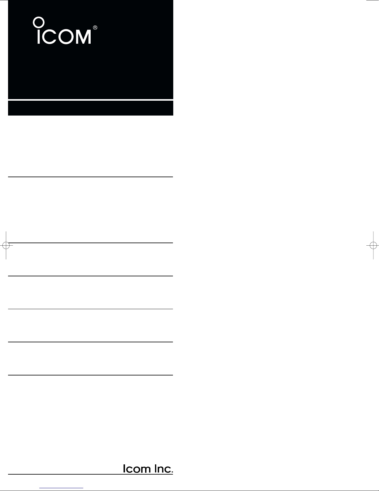
■ ID-RP1D
qw er t ui o !0 !1y
PANEL DESCRIPTION
1
q DATA A CONNECTOR [DATA A]
w DATA B CONNECTOR [DATA B]
Connects to ID-RP1L’s [DATA I/O].
e 10 BASE-T CONNECTOR [10 BASE-T]
Connects to a PC through the supplied Ethernet
cable for the repeater maintenance.
r 13.8V INPUT [DC 13.8V IN]
Connects to a DC power supply.
t OUTPUT POWER SELECT SWITCH [HIGH/LOW]
Select the transmit output power.
y POWER SWITCH [POWER]
Turn the repeater main power ON and OFF.
u POWER INDICATOR
Lights during the repeater power is ON
i SERVICE CONNECTOR [SERVICE]
Connect a PC through the supplied USB cable receptacle for the repeater maintenance.
o CONTROL B CONNECTOR [CONT B]
!0 CONTROL C CONNECTOR [CONT C]
!1 CONTROL D CONNECTOR [CONT D]
Connect the IC-RP1VS’s [CONT I/O] connector.
1
Page 4
PANEL DESCRIPTION
qwerty
qwert
1
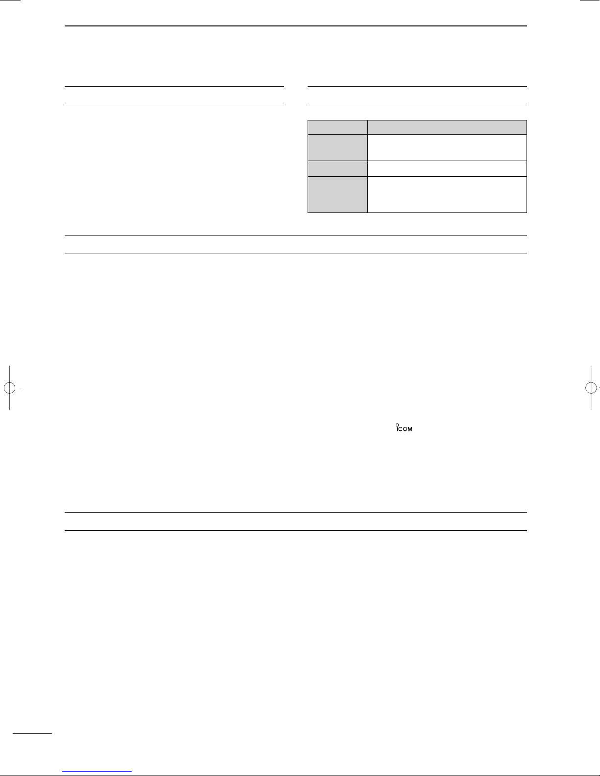
■ ID-RP1VS
q CONTROL I/O CONNECTOR [CONT I/O]
Connects to ID-RP1D’s [CONT B].
w OUTPUT POWER SELECT SWITCH [HIGH/LOW]
Select the transmit output power.
e POWER INDICATOR
Lights during the repeater power is ON
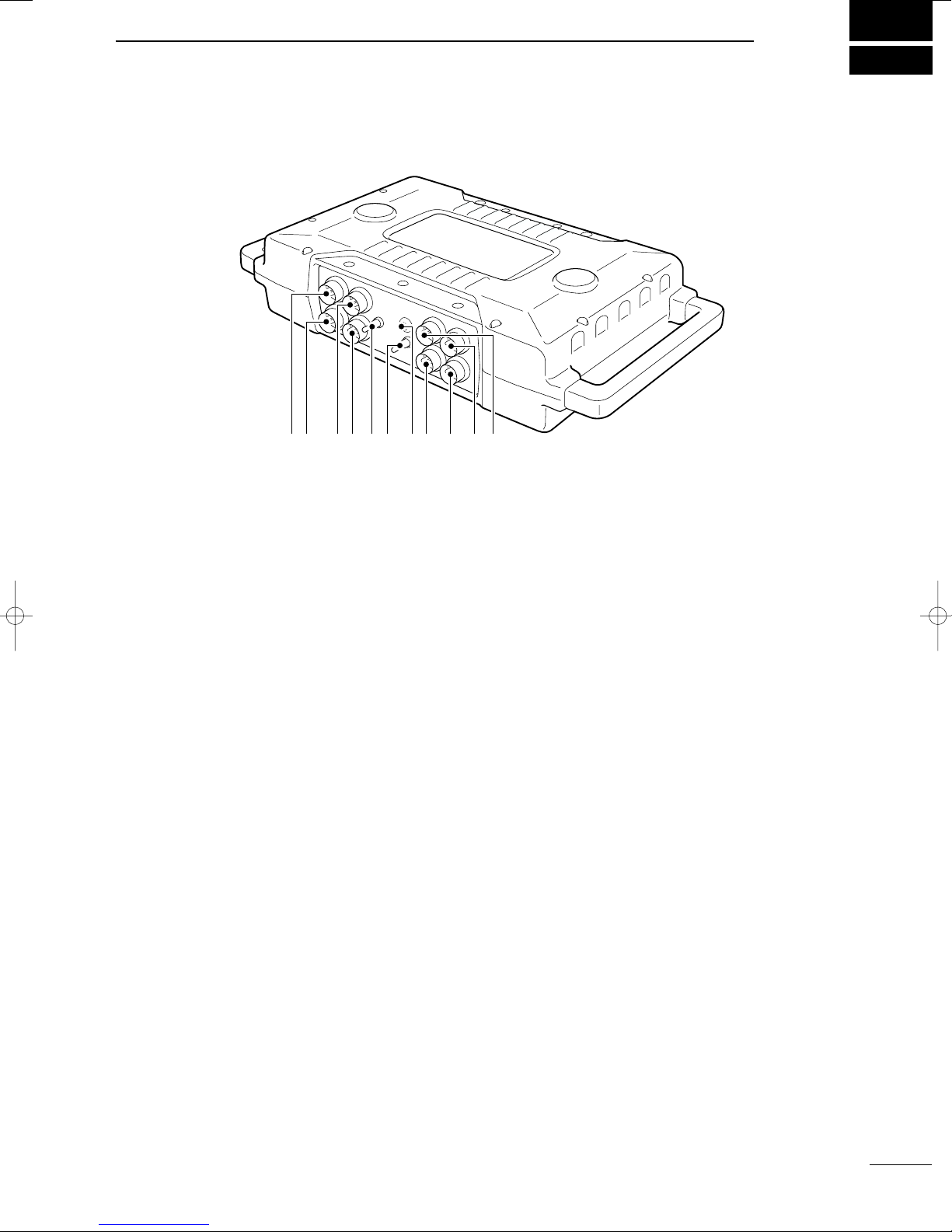
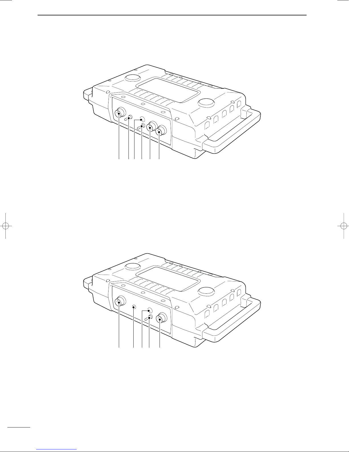
■ ID-RP1L
r POWER SWITCH [POWER]
Turn the repeater main power ON and OFF.
t SERVICE CONNECTOR [SERVICE]
Connect a PC through the supplied USB cable receptacle for the repeater maintenance.
y 13.8V INPUT [DC 13.8V IN]
Connects to a DC power supply.
q DATA I/O CONNECTOR [DATA I/O]
Connects to ID-RP1D’s [DATA A] or [DATA B] connector.
w RSSI OUTPUT CONNECTOR [RSSI]
Connects a voltameter for the parabolic antenna adjustment.
2
e POWER INDICATOR
Lights during the repeater power is ON
r POWER SWITCH [POWER]
Turn the repeater main power ON and OFF.
t 13.8V INPUT [DC 13.8V IN]
Connects to a DC power supply.
Page 5
■ Notch filter unit (EX-2659)
[toDUP]
Connect to the duplexer
unit [LOW] connector.
[toRX]
Connect to the ID-RP1VS
[RX] antenna connector.
[VOICE]
Connect to the duplexer
unit [COM] connector.
[D ATA]
Connect to the ID-RP1D
antenna connector.
[D_ANT]
Connect the short antenna
cable from the AH-1415.
[V_ANT]
Connect the long antenna
cable from the AH-1415.
[LOW]
Connect to the notch filter
unit [toDUP] connector.
[HIGH]
Connect to the ID-RP1VS
[TX] antenna connector.
[COM]
Connect to the canceller
unit [VOICE] connector.
■ Canceller unit (EX-2660)
PANEL DESCRIPTION
1
■ Duplexer (EX-2661)
3
Page 6
2
ID-RP1D
ID-RP1L
13.8 V DC
13.8 V DC
13.8 V DC
ID-RP1VS
AH-1415
AH-1045/1080
Canceller
unit
Duplexer
unit
Notch
filter
unit
Short
to [D_ANT]
to [DATA]
to [VOICE]
to [COM]
to [HIGH]
to [LOW]
to [RX]
2 m (6.6 ft) twist pair cable
(supplied with the ID-RP1L)
to [TX]
to
[CONT I/O]
to
[DATA A]*
to
[DATA I/O]
to
[CONT B]
to [toDUP]
to [toRX]
to [V_ANT]
Long
1 m (3.3 ft) twist pair cable
(supplied with the ID-RP1VS)
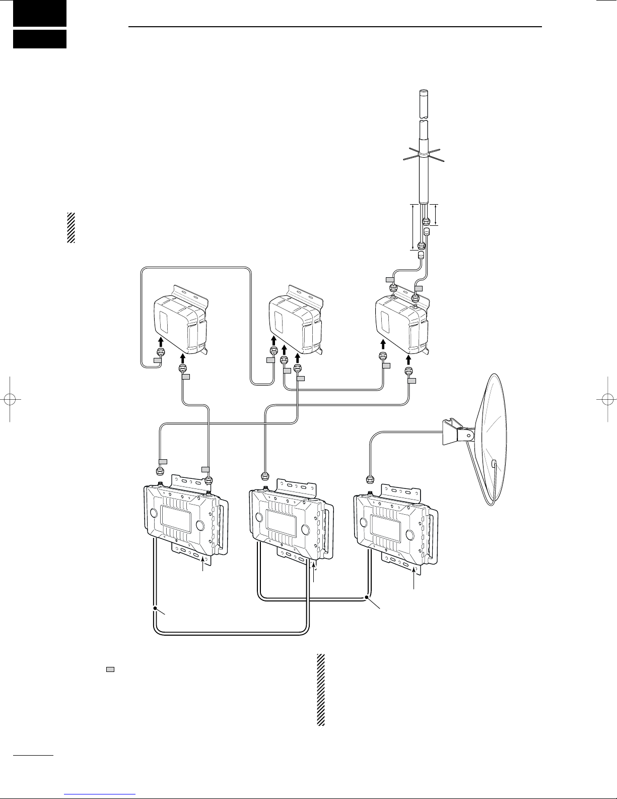
CONNECTIONS AND INSTALLATIONS
■ Connections
RDANGER
ID-RP1 is intended for professional installation only.
We are not responsible for any building breakage, any
damage resulting from a drop of ID-RP1 from a high
place or unstable site or resulting from any personal
injury nor any accident in any other cases. If ID-RP1 is
must be installed at such high place or unstable site,
be sure to consult an expert engineer.
IMPORTANT: Use the supplied connection cables
ONLY. NEVER extend the cables— system or com-
munication error may occur.
✔
For your convenience
A label (“” mark in the diagram above) is attached
near the connector on the supplied coaxial cable to
specifying the connection for guidance.
*Connecting connector can be selected with the ID-RP1D
maintenance application. (See page 19) Before operating
the repeater system, programming is necessary for both the
ID-RP1D and the ID-RP1VS.
4
CAUTION!: NEVER turn the ID-RP1L power ON
without connecting the parabolic antenna. The IDRP1L starts transmission after power ON. Transmission without antenna may damage the ID-RP1L.
IMPORTANT: After the connections, turn the IDRP1D power ON first to prevent system error.
Page 7
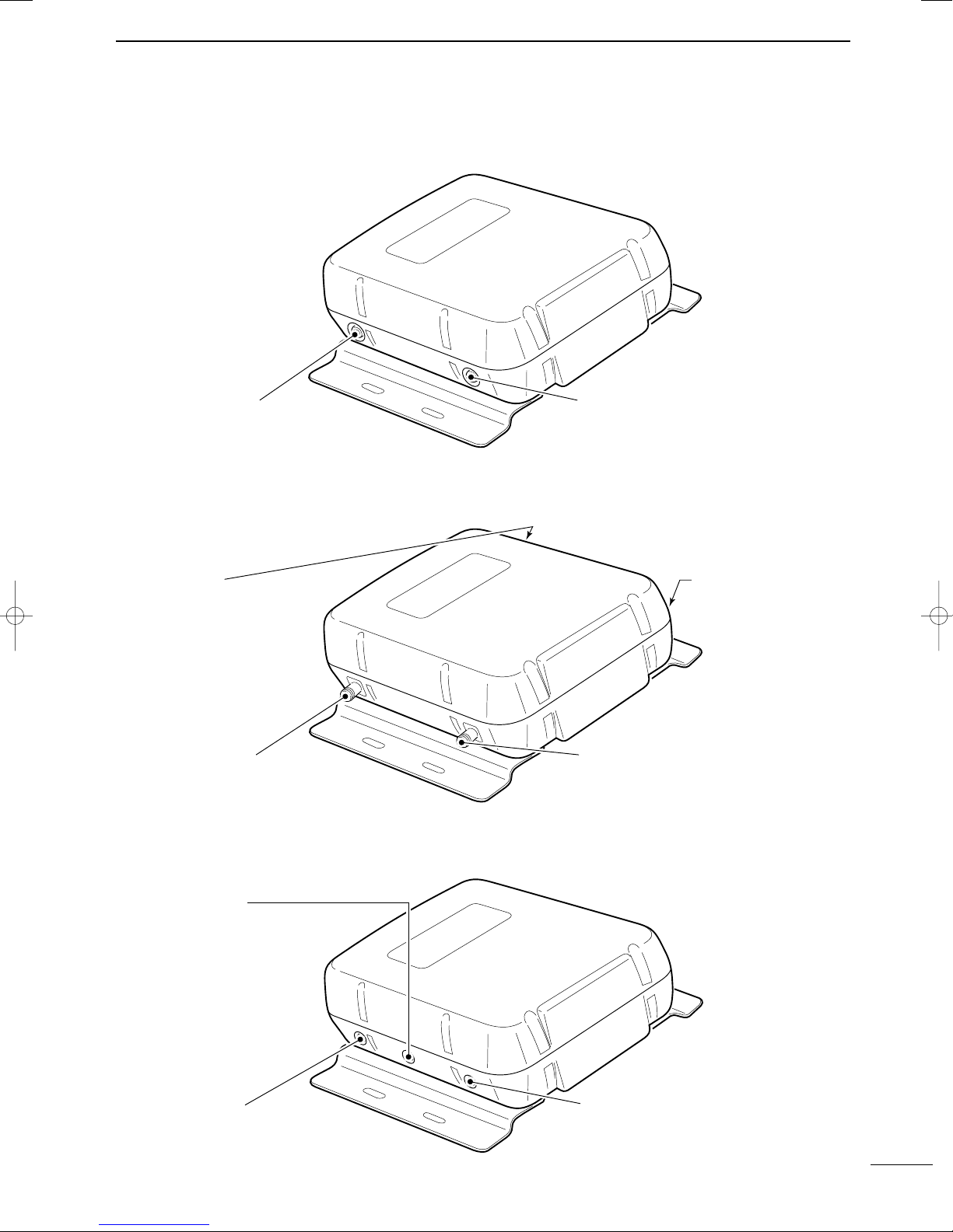
■ Mounting plate attachment
Bolt
Spring washer
Flat washer
Mounting plate
Flat washer
S-washer
Nut
Hex-head bolt
U-bolt
Pole clamp
Flat washer
S-washer
Nut
Pole (32–60 mm; 1
1
⁄4–23⁄8″ (d))
Flat washer
S-washer
Nut
Hex-head bolt
U-bolt
Pole clamp
Flat washer
S-washer
Nut
Pole (32–60 mm; 1
1
⁄4–23⁄8″ (d))
Attach the supplied mounting plates onto ID-RP1D, IDRP1VS, ID-RP1L, notch filter, canceller and duplexer
unit as illustrated at right.
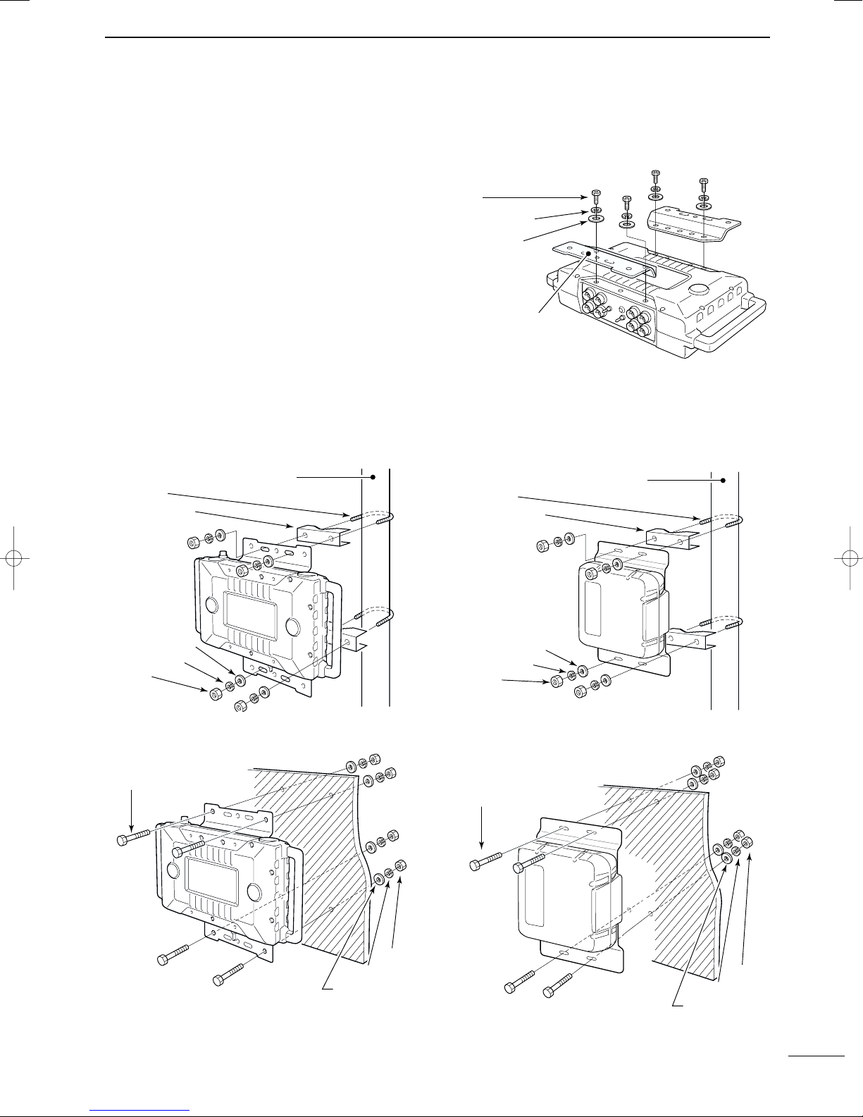
■ Mounting descriptions
DD
ID-RP1D/VS/L
• Mounting to a pole
CONNECTIONS AND INSTALLATIONS
• Example— ID-RP1D
DD
Notch filter/Duplexer/Canceller unit
• Mounting to a pole
2
• Mounting onto a wall
• Mounting onto a wall
5
Page 8

CONNECTIONS AND INSTALLATIONS
V-bolt
Pole
(32–60 mm
; 1
1
⁄4–23⁄8″ (d))
S-washer
Nut
Bracket
AH-1415
to canceller unit
Pole clamp
V-bolt
Pole
(32–60 mm; 1
1
⁄4–23⁄8″ (d))
S-washer
Nut
Bracket
AH-1415
to canceller unit
Pole clamp
2
DD
AH-1415 (1.2 GHz antenna)
• Mounting to a pole 1
DD
AH-1045/AH-1080
(10 GHz Offset-Parabola antenna)
Direction and angle adjustment is required for the AH1045/1080 installation. See the AH-1045/AH1080 instruction manual for both the installation and the
adjustment details.
• Mounting to a pole 2
6
Page 9

■ Connector information
o
u
t
q
e
r
y
!0
w
i
r
e
q
w
y
t
y
t
r
q
w
e
i
u
DD
[SERVICE] connector
Front view
DD
[10BASE-T] connector
Front view
Pin
1
2
3
4
5
6
7
8
9
10
Pin
1
2
3
4
5
6
Pin name
USB5V
USBDM
USBDP
USBGD
GND
USB5V
USBDM
USBDP
USBGD
GND
Pin name
TX+
TX–
NC
NC
RX+
RX–
Input terminal for USB 5 V of [USB1].
I/O terminal for –DATA of [USB1].
I/O terminal for +DATA of [USB1].
Ground terminal of [USB1].
F.G (shell) of [USB1].
Input terminal for USB 5 V of [USB2].
I/O terminal for –DATA of [USB2].
I/O terminal for +DATA of [USB2].
Ground terminal of [USB2].
F.G (shell) of [USB2].
Outputs data (+) and connected to RJ-45 pin 3.
Outputs data (–) and connected to RJ-45 pin 6.
No connection. (Connected to RJ-45 pin 4.)
No connection. (Connected to RJ-45 pin 5.)
Inputs data (+) and connected to RJ-45 pin 1.
Inputs data (–) and connected to RJ-45 pin 2.
CONNECTIONS AND INSTALLATIONS
Description
Description
2
DD
[CONT B], [CONT C], [CONT D], [DATA A], [DATA B] connectors
Front view
Pin
1
2
3
4
5
6
7
8
Pin name
RSSI
GND
TE
TD
TC
RD
RC
GND
Description
Becomes high level (3.3 V) when effective data (RD) is applied.
Connected to ground.
Becomes high level when effective data (TD) is output.
Outputs data, synchronous to “TC.”
Inputs clock signal for data transmission.
Inputs data, synchronous to “RC.”
Inputs clock signal for data reception.
Connected to ground.
7
Page 10

CONNECTIONS AND INSTALLATIONS
r
e
q
w
y
t
eryt qw
TX+
TX–
NC
NC
RX+
RX–
USB1USB2
USB5V
USB5V
USBDM
USBDM
USBDP
USBDP
USBGD
USBGD
GNDGND
o
utq
e
r
y!0w
q
er
wq
er
w
i
qw
2
DD
[DC 13.8V IN] connector
Front view
✔
For your information
Pin
1
2
Pin name
HV
GND
13.8 V DC ±10% input.
Connected to ground.
When extend the DC power cable (supplied DC
power cable length: 2 m; 6.6 ft), use the cable at least
3.5 mm2thick or better than AWG No. 12.
DD
Cable connection
• Service cable
Description
The DC power cable can be extended up to 20 m
(65 ft), however, confirm the DC voltage is in the guaranteed range, 13.8 V ±10% (12.42–15.18 V DC), at
the [DC 13.8V IN] connector while transmitting with
high output power setting.
• Ethernet cable
8
Page 11

DRIVER INSTALLATION
Click
Click
Click
Select
3
The same USB driver, supplied with the ID-1 is usable
for the ID-RP1D/VS frequency programming software
■ Microsoft®Windows®XP
q Connect the ID-RP1D/VS [SERVICE] connector
and the PC USB port through an USB cable and
connector converter.
• Turn the power ON.
•“Found New Hardware USB < - > Serial” appears first,
then “Found New Hardware USB High Speed Serial Converter” appears as below.
w The “Found New Hardware Wizard” will come up as
below. Insert the supplied CD into the CD drive, select “Install the software automatically (Recommended)”, then click [Next>].
The displayed dialog boxes or indications may differ slightly from the following instructions according
to your system conditions, or environment.
r While searching the driver, the “Hardware Installa-
tion” dialog box appears as below.
Click [Continue Anyway] to start the installation.
t Windows starts installing the USB driver.
e The wizard starts searching for the driver and
shows the dialog below during search.
y After the installation is completed, click [Finish].
u After clicking [Finish], the dialog appears as below.
i Eject the CD.
• Rebooting the PC is recommended.
9
Page 12

DRIVER INSTALLATION
Click
Click
Click
Click
Select
Click
Select
Click
3
■ Microsoft®Windows®98/Me
q Connect the ID-RP1D/VS [SERVICE ] connector
and the PC USB port through an USB cable and
connector converter.
• Turn the power ON.
•“New Hardware is found” dialog box appears.
w The “Add New Hardware Wizard” will come up as
below. Click [Next>].
e Select “Search for the best driver for your device
(Recommended).”, then click [Next>].
t When the driver is found, the following dialog is dis-
played. Click [Next>] to start the installation.
NOTE: When the appropriate driver is not found, a
different dialog is displayed. In such case, select
“Specify a location” and type “D:\driver” in the text
box to select the “Driver” folder in the CD (if CD
drive is D) in step r.
y After the installation is completed, the following dia-
log is displayed. Click [Finish] to finish the installation.
r Select “CD-ROM drive,” and insert the supplied CD
into the drive, then click [Next>].
10
u The “Add New Hardware Wizard” will come up
again as below. Click [Next>].
Page 13

i Select “Search for the best driver for your device
Click
Click
Click
Select
(Recommended).”, then click [Next>].
o When the driver is found, the following dialog is dis-
played. Click [Next>] to start the installation.
DRIVER INSTALLATION
3
!0 After the installation is completed, the following dia-
log is displayed. Click [Finish] to finish the installation.
!1 Eject the CD.
• Rebooting the PC is recommended.
11
Page 14

DRIVER INSTALLATION
Click
Click
Click
Click
Select
Click
Select
Click
3
■ Microsoft®Windows®2000
q Connect the ID-RP1D/VS [SERVICE ] connector
and the PC USB port through an USB cable and
connector converter.
• Turn the power ON.
•“Found New Hardware” dialog box appears below.
w The “Found New Hardware Wizard” will come up as
below. Click [Next>].
t When the driver is found, the following dialog is dis-
played. Click [Next>] to start the installation.
NOTE: When the appropriate driver is not found, a
different dialog is displayed. In such case, click
[<Back], select “Specify a location”, click [Next>],
then type “D:\driver” in the text box to select the “Driver” folder in the CD (if CD drive is D).
e Select “Search for a suitable driver for my device
(recommended)”, then click [Next>].
r Select “CD-ROM drives”, and insert the supplied
CD into the CD drive, then click [Next>].
y After the installation is completed, click [Finish].
u The “Found New Hardware” wizard appears again.
i Click [Next>].
12
Page 15

DRIVER INSTALLATION
Click
Click
Click
Select
Click
Select
3
o Select “Search for a suitable driver for my device
(recommended)”, then click [Next>].
!0 Select “CD-ROM drives”, then click [Next>].
!2 After the installation is completed, click [Finish].
!3 Eject the CD.
• Rebooting the PC is recommended.
!1 When the driver is found, the following dialog is dis-
played. Click [Next>] to start the installation.
NOTE: When the appropriate driver is not found, a
different dialog is displayed. In such case, click
[<Back], select “Specify a location”, click [Next>],
then type “D:\driver” in the text box to select the “Driver” folder in the CD (if CD drive is D).
13
Page 16

DRIVER INSTALLATION
Confirm the USB serial port availability and the COM port
number.
(In this example, the USB serial port number is “3.”)
Click
Click
Double click
3
■ COM port confirmation
After the driver installation, confirm the driver availability and the port number are recommended.
In this section, screen shots of Windows XP are used
for instruction example. However, the instructions are
similar to another operating systems, Windows 98, Me
and 2000.
q Boot up the Windows.
w Select the “Control Panel” in the Start menu.
• Control panel appears as shown in the next step below.
e Double click the “Performance and Maintenance.”
• Performance and Maintenance menu appears.
y Click “” of the “Ports (COM & LPT)” to display the
usable COM port and the port number.
u Confirm the USB serial port availability and the
COM port number.
• The COM port number is used for the COM port setup.
(p. 17)
r Double click the “System,” then click the “Hardware”
tub in the displayed System Propaties screen.
t Click the “Device Manager.”
• Device Manager screen appears as below.
i Close the Device Manager, System Propaties
screen and then Control panel.
14
Page 17

APPLICATION INSTALLATION
Click
Click
Click
Double click
■ Application installation
q Insert the CD into the CD drive.
w Open the CD drive contents via “My computer” or
“Windows Exproler.”
•“Driver,” “ID-RP1-TXRX” and “ID-RP1D” folders are
available.
e Double click “setup.exe” file in “ID-RP1-TXRX” or
“ID-RP1D” folder.
4
t Confirm the location, then click [Next].
• Click [Browse...] then type the desired location if you
specifying the installation location.
y Click [Next] to start the installation.
• The Windows Installer starts preparing the installation.
r After the preparation, the following dialog is dis-
played. Click [Next].
u Shows the dialog as below while installing.
15
Page 18

APPLICATION INSTALLATION
Click
4
i After the installation is completed, click [Close].
u Eject the CD.
• Rebooting the PC is recommended.
16
Page 19

SETTING THE REPEATER
Enter the desired
frequency here.
Click
Enter the desired
frequency here.
Click
Click
Enter the appropriate
port number here.
Click
Click
• ID-RP1D • ID-RP1VS
to [SERVICE]
USB1
for transmit
USB1
USB2
for receive
to [SERVICE]
to PC to PC
■ General
The ID-RP1 TX/RX module maintenance programs repeater operating frequencies, and the ID-RP1D maintenance programs call signs for the repeaters.
■ Repeater frequency setting
q Connect the PC and either ID-RP1D or ID-RP1VS
[SERVICE] connector using the USB service cable.
• The connector converter for the ID-RP1VS has 2 USB
connectors for setting receive and transmit frequencies
independently.
5
y Click [Edit] to displays the frequency setup screen.
• The displaying screen is different according to the connected unit and port.
w Turn the repeater unit power ON.
e Select the “ID-RP1 TX/RX module maintenance”
menu in the program menu to start up the application.
r Click [SETUP].
t Enter the appropriate USB port number in the “Port
Number” cell, then click [Set].
• The BaudRate is the fixed value.
• The screen disappears after clicking [Set].
• This setting is necessary for the first time only.
u Enter the desired frequency in the Frequency cell,
then click [Store].
• After clicking [Store], the screen disappears.
• When connecting to ID-RP1D
• When connecting to ID-RP1VS
i Click [EXIT] to quit the application.
17
Page 20

SETTING THE REPEATER
Click
Click
Enter the desired new
password.
Click
Enter the appropriate MAC and
IP addresses with the PC.
Click
to [10BASE-T]
to PC
5
■ Call sign setting
q Connect the PC and the ID-RP1D [SERVICE] con-
nector using the Ethernet service cable.
IMPORTANT: Connect the PC to the ID-RP1D
directly. NEVER connect them via a router or a
HUB.
w Turn the ID-RP1D power ON.
e Select the “ID-RP1D maintenance” menu in the pro-
gram menu to start up the application.
r Click [SETUP].
y Click [Password], if you want to change the pass-
word.
•“PASSWORD” is set as the default.
u Type the desired new password into the New Pass-
word and type the same password again into New
Password (retype) cells.
• The typed characters are masked with “✱ (asterisk).”
t Enter the appropriate MAC and IP addresses with
the PC.
• The MAC address must not be FF:FF:FF:FF:FF:FF, as
well as the different MAC address from the PC.
• The IP address must not be 255.255.255.255, must not
the same as the MAC address, as well as must be use
the same subnet mask with the PC.
Hint!
When the PC accessing to the ID-RP1D with the default
settings, the PC must be set as the following conditions.
- IP address : Use 192.168.0.1
- DNS : Not used
- Subnet mask : Use 255.255.255.0
- Default Gateway : Not used
i Click [Set] to set the new password and close the
Change Password screen.
o Click [Set] to close the Setup screen.
18
Page 21

SETTING THE REPEATER
Click
Click then select “Repeater 1.”
Type the specified call sign of a nearby
ID-RP1D to be linked.
Click to display “✔” mark.
Click then select “Repeater 1.”
Type the specified call sign of the connected
ID-RP1D.
Click to display “✔” mark.
Click
5
!0 Click [EDIT].
• The PC start to read ID-RP1D current settings.
• After read the all settings, Edit Parameters screen ap-
pears.
!1 Type the specified call sign for the connected ID-
RP1D into the Repeater 1’s cell.
!3 Click the “Repeater 2” check box to displays “✔”
mark, when setting a nearby repeater for repeater
link operation.
!4 Click Data A “” button in the “Adjacent Repeaters”
then select “Repeater 2” to
!2 Click “” button in the “This Repeater” then select
“Repeater 1” to
!5 Repeat the steps !3 when setting another nearby
repeaters call signs, and repeat the steps !4 when
linking another repeater.
!6 Click [OK] to program the setting into the ID-RP1D
and close the screen.
19
Page 22

A-6247I-1EX
Printed in Japan
© 2002 Icom Inc.
1-1-32 Kamiminami, Hirano-ku, Osaka 547-0003 Japan
 Loading...