

Page 1
INSTRUCTION MANUAL
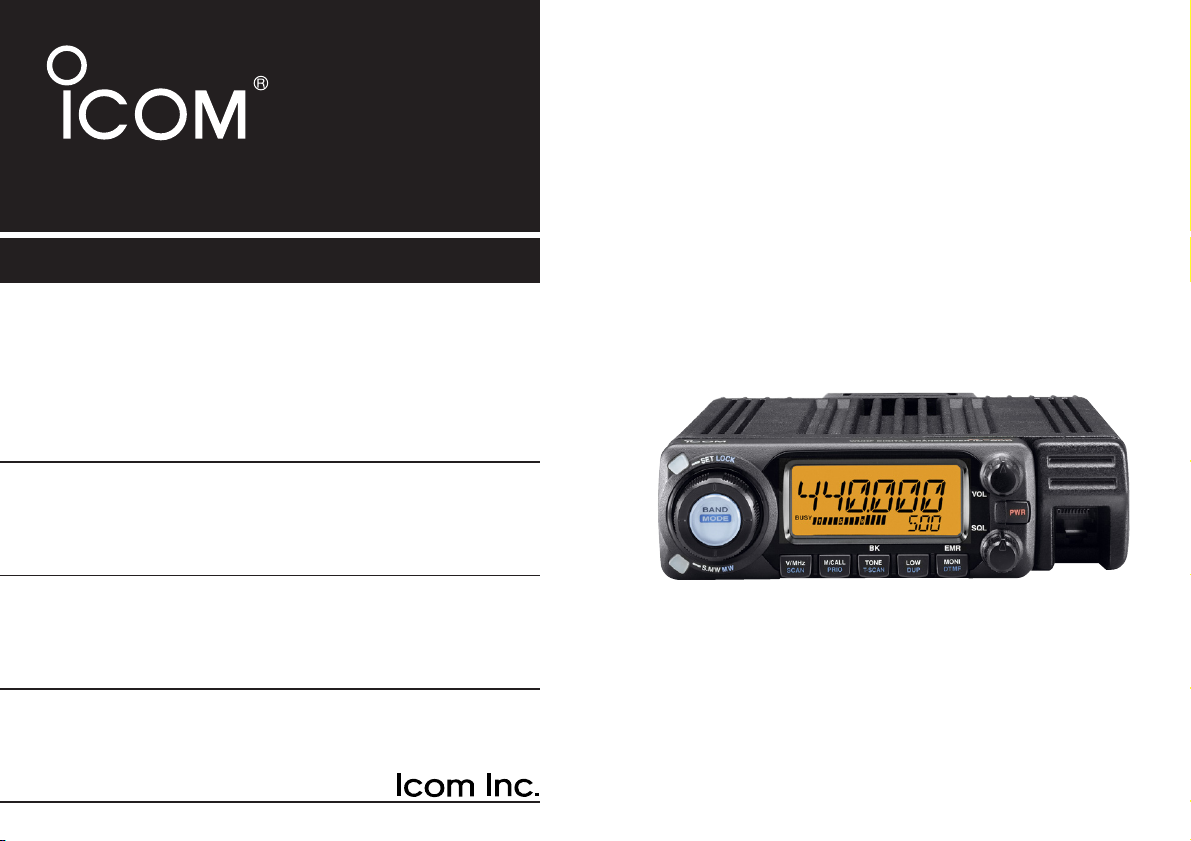
ID-800H
VHF/UHF DIGITAL TRANSCEIVER
This device complies with Part 15 of the FCC rules. Operation is subject to the following two conditions: (1) This device may not cause
harmful interference, and (2) this device must accept any interference
received, including interference that may cause undesired operation.
Page 2

i
Thank you for purchasing this Icom product. The ID-800H
VHF/UHF DIGITAL TRANSCEIVER
is designed and built with Icom’s
state of the art technology and craftsmanship. With proper care,
this product should provide you with years of trouble-free operation.
We want to take a couple of moments of your time to thank
you for making your ID-800H your radio of choice, and hope
you agree with Icom’s philosophy of “technology first.” Many
hours of research and development went into the design of
your ID-800H.
DD
FEATURES
❍ DV mode (Digital voice + low-speed data
communication) available
– GPS receiver connection
– Text message and call sign exchange
❍ Switchable VHF and UHF transceiver
❍ 55 W*—high transmit output power
*VHF band; 50 W for UHF band
❍ Detachable controller for flexible installation
❍ Large tuning dial and band switch button
❍ Selectable backlit color from amber, green
and yellow
❍ Total 512 memory channels with bank link
scan
❍ Remote control microphone standard
FOREWORD
Page 3
ii
IMPORTANT
READ ALL INSTRUCTIONS carefully and completely
before using the transceiver.
SAVE THIS INSTRUCTION MANUAL— This in-
struction manual contains important operating instructions for
the ID-800H.
EXPLICIT DEFINITIONS
WORD DEFINITION
R WARNING!
CAUTION
NOTE
Personal injury, fire hazard or electric shock
may occur.
Equipment damage may occur.
Recommended for optimum use. No risk of
personal injury, fire or electric shock.
Icom, Icom Inc. and the logo are registered trademarks of Icom
Incorporated (Japan) in the United States, the United Kingdom, Germany, France, Spain, Russia and/or other countries.
Page 4

iii
RWARNING RF EXPOSURE!This device emits Radio
Frequency (RF) energy. Extreme caution should be observed when
operating this device. If you have any questions regarding RF exposure and safety standards please refer to the Federal Communications Commission Office of Engineering and Technology’s report on
Evaluating Compliance with FCC Guidelines for Human Radio frequency Electromagnetic Fields (OET Bulletin 65).
RWARNING! NEVERconnect the transceiver to an AC out-
let. This may pose a fire hazard or result in an electric shock.
RWARNING! NEVER operate the transceiver while driving a
vehicle. Safe driving requires your full attention—anything less may
result in an accident.
NEVER connect the transceiver to a power source of more than
16 V DC. This will damage the transceiver.
NEVER connect the transceiver to a power source using reverse
polarity. This will damage the transceiver.
NEVER cut the DC power cable between the DC plug and fuse
holder. If an incorrect connection is made after cutting, the transceiver
may be damaged.
NEVER expose the transceiver to rain, snow or any liquids. The
transceiver may be damaged.
NEVERoperate or touch the transceiver with wet hands. This may
result in an electric shock or damage the transceiver.
NEVERplace the transceiver where normal operation of the vehi-
cle may be hindered or where it could cause bodily injury.
NEVER let objects impede the operation of the cooling fan on the
rear panel.
DO NOT push the PTT when not actually desiring to transmit.
DO NOT allow children to play with any radio equipment contain-
ing a transmitter.
During mobile operation,
DO NOT operate the transceiver with-
out running the vehicle’s engine. When the transceiver’s power is ON
and your vehicle’s engine is OFF, the vehicle’s battery will soon become exhausted.
AVOID using or placing the transceiver in direct sunlight or in
areas with temperatures below –10°C (+14°F) or above +60°C
(+140°F).
BE CAREFUL! The transceiver will become hot when operat-
ing it continuously for long periods.
AVOID setting the transceiver in a place without adequate venti-
lation. Heat dissipation may be affected, and the transceiver may be
damaged.
AVOIDthe use of chemical agents such as benzine or alcohol
when cleaning, as they can damage the transceiver’s surfaces.
USE Icom microphones only (supplied or optional). Other manu-
facturer’s microphones have different pin assignments and may damage the transceiver if attached.
For U.S.A. only
CAUTION: Changes or modifications to this device, not ex-
pressly approved by Icom Inc., could void your authority to
operate this device under FCC regulations.
PRECAUTIONS
Page 5
iv
SUPPLIED ACCESSORIES
q DC power cable (3 m) ………………………………………1
w Mobile mounting bracket …………………………………1
e Microphone (HM-133)* ……………………………………1
r Fuse (20 A) …………………………………………………1
t Mounting screws, nuts and washers …………………1 set
y Microphone hanger …………………………………………1
u Separation cable
†
(3.5 m; 11.5 ft) …………………………1
*HM-118N
HAND MICROPHONE
supplied versions are also available.
†
Aferrite core is adapted for the USA version.
qw
ert
yu
Page 6

v
FOREWORD .............................................................................. i
IMPORTANT ............................................................................. ii
EXPLICIT DEFINITIONS .......................................................... ii
PRECAUTIONS ....................................................................... iii
SUPPLIED ACCESSORIES ..................................................... iv
TABLE OF CONTENTS ............................................................ v
QUICK REFERENCE GUIDE ............................................... I–X
■ Installation .......................................................................... I
■ Your first contact ............................................................. VII
■ Repeater operation .......................................................... IX
■ Programming memory channels ....................................... X
1PANEL DESCRIPTION .................................................. 1–10
■ Front panel—controller ..................................................... 1
■ Function display ................................................................ 3
■ Rear panel ........................................................................ 5
■ Microphone (HM-133) ....................................................... 7
■ Microphone keypad .......................................................... 8
■ Optional microphone (HM-118N) ..................................... 10
2 SETTING A FREQUENCY ........................................... 1 1–14
■ Preparation ...................................................................... 11
■ Using the tuning dial ....................................................... 12
■ Using the [Y]/[Z] keys .................................................... 12
■ Using the keypad ............................................................ 12
■ Tuning step selection ...................................................... 13
■ Lock functions ................................................................. 14
3 BASIC OPERATION .................................................... 15–19
■ Mode selection ................................................................ 15
■ Receiving ........................................................................ 16
■ Monitor function .............................................................. 16
■ Squelch attenuator .......................................................... 17
■ Audio mute function ........................................................ 18
■ Transmitting .................................................................... 18
■ Selecting output power ................................................... 19
■ One-touch PTT function .................................................. 19
4 REPEATER OPERATION ............................................ 20–27
■ General ........................................................................... 20
■ Accessing a repeater ...................................................... 21
■ Subaudible tones (Encoder function)............................... 23
■ Offset frequency ............................................................. 26
■ Auto repeater (USA version only) ................................... 27
5 MEMORY OPERATION ............................................... 28–39
■ General description ......................................................... 28
■ Memory channel selection .............................................. 28
■ Programming a memory channel .................................... 29
■ Copying memory contents .............................................. 31
■ Programming channel names ........................................ 33
■ Memory clearing ............................................................. 36
■ Memory bank selection ................................................... 37
■ Memory bank setting ...................................................... 38
■ Transferring bank contents ............................................. 39
6 CALL CHANNEL OPERATION ................................... 40–41
■ Call channel selection ..................................................... 40
■ Call channel transferring ................................................. 40
■ Programming a call channel ........................................... 41
7 SCAN OPERATION ..................................................... 42–48
■ Scan types ...................................................................... 42
■ Scan start/stop ................................................................ 43
■ Scan edges programming ............................................... 45
TABLE OF CONTENTS
Page 7

vi
■ Skip channel setting ........................................................ 47
■ Scan resume condition ................................................... 48
8 PRIORITY WATCH ....................................................... 49–50
■ Priority watch types ......................................................... 49
■ Priority watch operation .................................................. 50
9 DTMF MEMORY ENCODER ........................................ 51–54
■ Programming a DTMF code ........................................... 51
■ Transmitting a DTMF code ............................................. 53
■ DTMF speed ................................................................... 54
10POCKET BEEP AND TONE SQUELCH ...................... 55–59
■ Pocket beep operation .................................................... 55
■ Tone/DTCS squelch operation ........................................ 58
■ Tone scan ....................................................................... 59
11DIGITAL MODE OPERATION ...................................... 60–79
■ Digital mode operation .................................................... 60
■ Call sign programming .................................................... 60
■ Digital voice mode operation .......................................... 63
■ When receiving a digital call ........................................... 66
■ Break-in communication ................................................. 67
■ EMR communication ....................................................... 67
■ Pocket beep operation .................................................... 68
■ Digital squelch function ................................................... 69
■ About D-STAR system .................................................... 70
■ Repeater call sign programming ..................................... 71
■ Low-speed data communication ..................................... 73
■ Message items ................................................................ 74
■ GPS operation ................................................................ 77
12OTHER FUNCTIONS ................................................. 80–106
■ Set mode ........................................................................ 80
■ Initial set mode ................................................................ 92
■ Weather channel operation (USA version only) .............. 99
■ Packet operation ........................................................... 100
■ Microphone keys ........................................................... 103
■ Partial reset ................................................................... 104
■ All reset ......................................................................... 104
■ Data cloning .................................................................. 105
13MAINTENANCE ....................................................... 107–108
■ Troubleshooting ............................................................ 107
■ Fuse replacement ......................................................... 108
14SPECIFICATIONS AND OPTIONS .......................... 109–110
■ Specifications ................................................................ 109
■ Options .......................................................................... 110
15MODE ARRANGEMENT .......................................... 11 1–1 14
1
2
3
4
5
6
7
8
9
10
11
12
13
14
15
Page 8
I
QUICK REFERENCE GUIDE
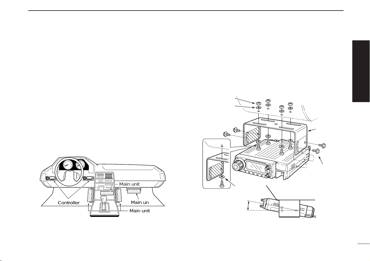
■ Installation
D Installation methods
•Single body installation
• The supplied mounting bracket (or optional MB-17A) can be
used for the main unit installation.
• Remote installation
• The supplied OPC-600/R
SEPARATION CABLE
can be used for
remote installation.
• Optional OPC-601/R
SEPARATION CABLE
(7 m; 23 ft) is avail-
able for extend installation.
• Optional MB-58
REMOTE CONTROLLER BRACKET
and MB-65
MOUNTING BASE
are available for increasing front panel
mounting possibilities.
• Optional OPC-440
MICROPHONE CABLE
(5.0 m; 16.4 ft) and
OPC-647 (2.5 m; 8.2 ft) are available to extend the microphone cable.
• Optional OPC-441
SPEAKER CABLE
(5.0 m; 16.4 ft) is avail-
able to extend the speaker cable.
Main unit
Front panel
Transceiver
Page 9
II
QUICK REFERENCE GUIDE
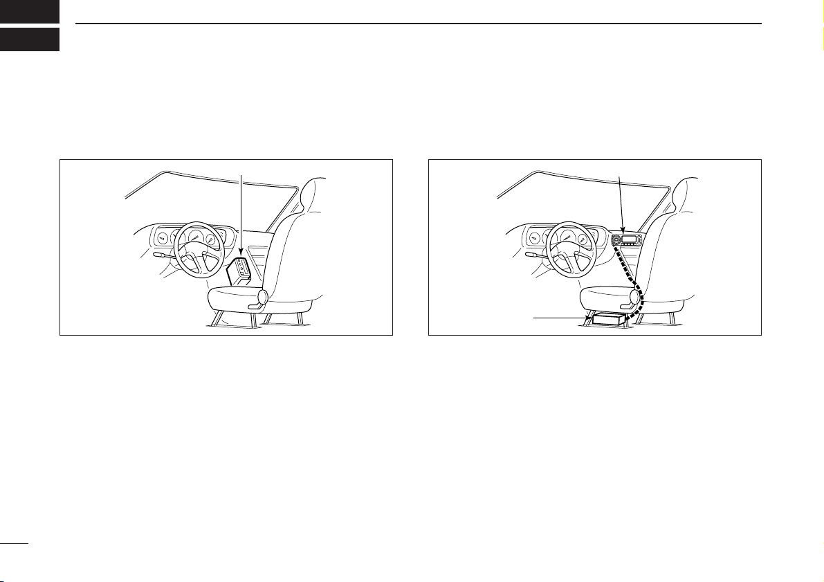
D Location
Select a location which can support the weight of the transceiver and does not interfere with driving. We recommend the
locations shown in the diagram below.
NEVER place the transceiver or remote controller where normal operation of the vehicle may be hindered or where it
could cause bodily injury.
NEVER place the transceiver or remote controller where air
bag deployment may be obstructed.
DO NOT place the transceiver or remote controller where hot
or cold air blows directly onto it.
AVOID placing the transceiver or remote controller in direct
sunlight.
D Using the mounting bracket
qDrill 4 holes where the mounting bracket is to be installed.
• Approx. 5.5–6 mm (1⁄4″) when using nuts; approx. 2–3 mm (1⁄8″)
when using self-tapping screws.
wInsert the supplied screws, nuts and washers through the
mounting bracket and tighten.
eAdjust the angle for your suitable position.
25˚
Nut
Spring washer
When using
self-tapping
screws
Flat washer
Mounting nut
Mounting
bracket
Controller
Main unit
Main unit
Main unit
Quick reference guide
Page 10
III
QUICK REFERENCE GUIDE
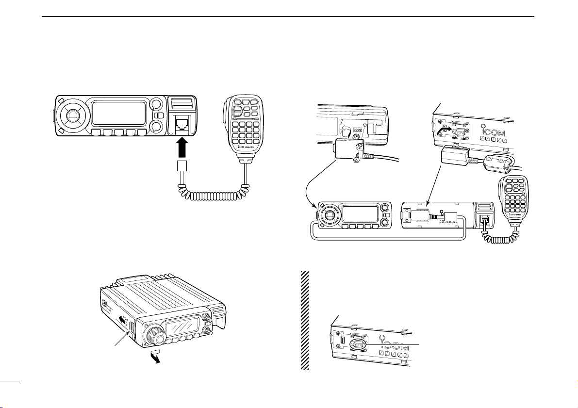
D Microphone connection
Connect the supplied microphone as illustrated below.
D Separation cable connection
Using the supplied separation cable (3.5 m; 11.5 ft) or the optional separation cable (7 m; 23 ft), the controller can be separated from the main unit, doubling as a remote controller.
qDetach the controller as below.
wConnect a separation cable between the controller and
main unit using the supplied screws as illustrated below.
A ferrite core is adapted for the USA version.
CAUTION!
NEVER short the terminals of the separation connector.
The 13.8 V power line is available in the connector, so the
transceiver may damage when short circuited.
NEVER short the terminals
• Controller’s rear panel • Main unit
OPC-600/R or OPC-601/R
q
w
e
Release latch
Page 11
IV
QUICK REFERENCE GUIDE
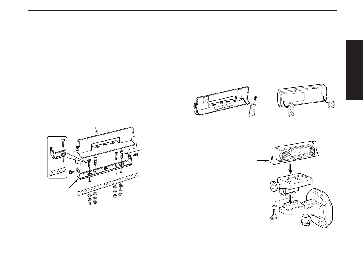
D Optional MB-58 installation
The optional MB-58
REMOTE CONTROLLER BRACKET
is avail-
able for separate installation.
qDrill 2 or 4 holes where the bracket is to be installed.
• Approx. 4 mm (1⁄8″) when using nuts; approx. 1–2 mm (1⁄16″)
when using self-tapping screws.
wInsert the supplied screws, bolts and washers through the
mounting base and tighten.
eAdjust the angle for the clearest view of the function dis-
play and tighten 2 screws when the mounting base is used.
rAttach the supplied Velcro pads (large) to the remote con-
troller and bracket.
tAttach the supplied Velcro pads (small) or rubber pad to
the bracket as shown below; then attach the remote controller.
• When using the optional MB-65
MB-58
MB-65
Adjust the viewing angle
for maximum visibility of
the function display.
MB-58 ID-800H remote controller
Bracket
When using selftapping screws.
Mounting
base
Mounting
bolt
Quick reference guide
Page 12
V
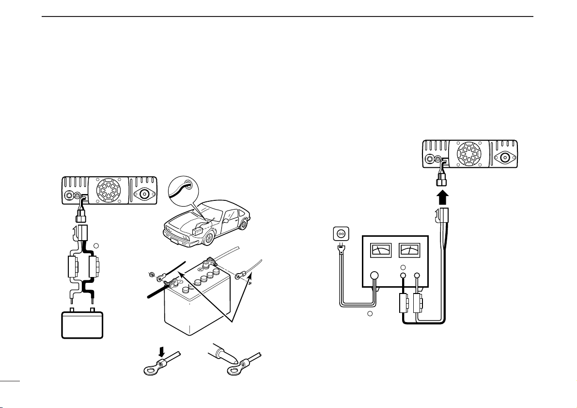
D Battery connection
RWARNING! NEVER remove the fuse holders from the DC
power cable.
NEVER connect the transceiver directly to a 24 V battery.
DO NOT use the cigarette lighter socket for power connec-
tions. (See p. 6 for details)
Attach a rubber grommet when passing the DC power cable
through a metal plate to prevent a short circuit.
• CONNECTING TO A DC POWER SOURCE
D DC power supply connection
Use a 13.8 V DC power supply with at least 15 A capacity.
Make sure the ground terminal of the DC power supply is
grounded.
• CONNECTING TO A DC POWER SUPPLY
See p. 108 for fuse replacement.
DC power
supply 13.8 V
to an
AC
outlet
Fuses
20 A
black
red⊕
−
⊕
−
ID-800H
ID-800H
Fuses
20 A
black
red⊕
−
12 V
Grommet
NOTE:
Use terminals for the
cable connections.
WARNING!
NEVER
remove the
fuse holders.
Crimp
Solder
12 V
battery
Supplied
DC power cable
+ red
_ black
QUICK REFERENCE GUIDE
Page 13
VI
QUICK REFERENCE GUIDE
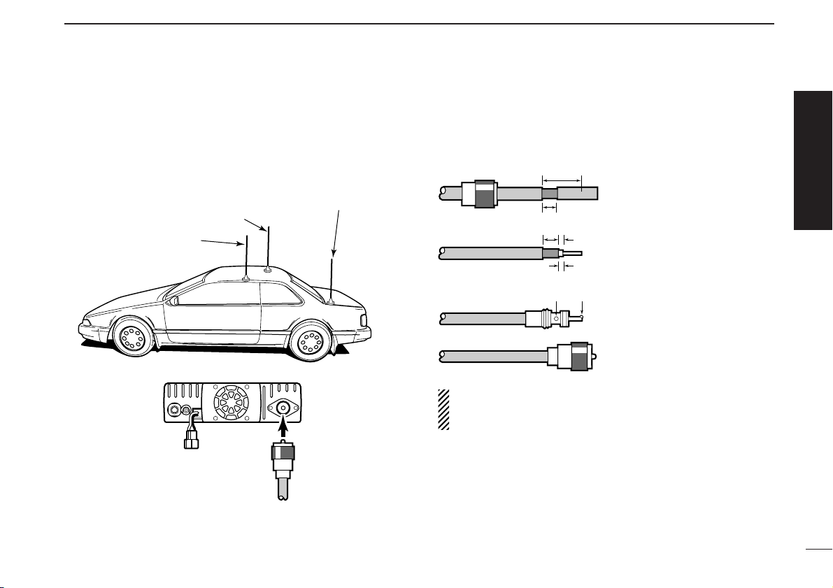
D Antenna installation
• Antenna location
To obtain maximum performance from the transceiver, select
a high-quality antenna and mount it in a good location. A nonradial antenna should be used when using a magnetic mount.
• Antenna connector
The antenna uses a PL-259 connector.
• PL-259 CONNECTOR
q Slide the coupling ring
down. Strip the cable
jacket and soft solder.
w Strip the cable as shown
at left. Soft solder the center conductor.
e Slide the connector body
on and solder it.
r Screw the coupling ring
onto the connector body.
(10 mm ≈3⁄8 in)
NOTE: There are many publications covering proper antennas and their installation. Check with your local dealer
for more information and recommendations.
Quick reference guide
Roof-mount antenna
(Drill a hole or use a magnetic mount.)
Gutter-mount antenna
Trunk-mount
antenna
30 mm
Coupling ring
10 mm (soft solder)
10 mm
1–2 mm
solder solder
Soft
solder
To antenna
Page 14
VII
QUICK REFERENCE GUIDE
■ Your first contact
Now that you have your ID-800H installed in your car or
shack, you are probably excited to get on the air. We would
like to take you through a few basic operation steps to make
your first “On The Air” an enjoyable experience.
1. Turning ON the transceiver
Before powering up your ID-800H, you may want to make
sure the audio volume and squelch level controls are set in
9–10 o’clock positions.
Although you have purchased a brand new transceiver, some
settings may be changed from the factory defaults because
of the quality control process. Resetting the CPU is necessary to start from factory default.
➥ While pushing both [SET•LOCK] and [S.MW•MW], push
and hold [PWR] for 1 sec. to reset the CPU.
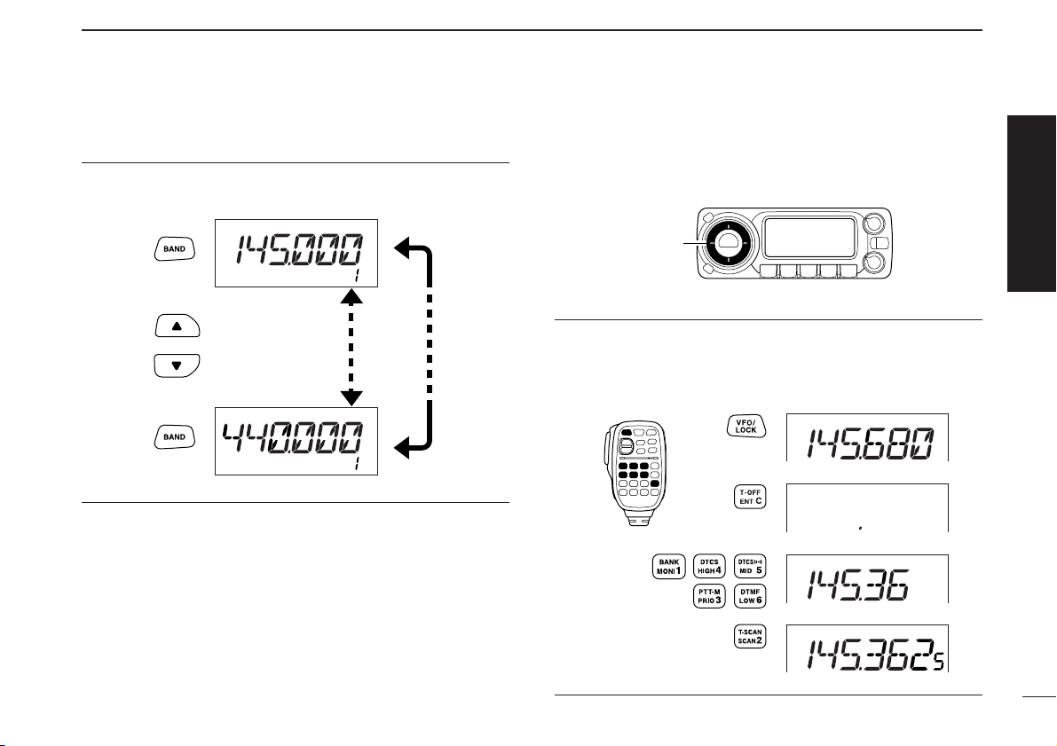
2. Selecting the operating frequency band
The ID-800H has 2 m and 70 cm transmittable bands.
➥ Push [BAND•MODE] momentarily to enter band selection
mode.
➥ Rotate [DIAL] to select the desired frequency band, then
push [BAND•MODE] to set the selected band.
[DIAL]
[BAND•MODE]
[PWR]
[SET•LOCK]
[S.MW•MW]
[VOL]
[SQL]
Page 15
VIII
QUICK REFERENCE GUIDE
Using the HM-133
You can select the desired frequency band from the HM-133.
3. Tune the frequency
The tuning dial will allow you to dial in the frequency you want
to operate. Pages 12 and 13 will instruct you on how to adjust
the tuning step size.
Using the HM-133
You can directly enter the frequency with the HM-133 keypad
for the main band.
[EXAMPLE]: Setting frequency to 145.3625 MHz.
Push
Push
Push
Push
Rotate [DIAL] to tune to the frequency.
[DIAL]
Push
push
Then
Push or to select the band.
Quick reference guide
Page 16
IX
QUICK REFERENCE GUIDE
■ Repeater operation
1. Setting duplex
➥ Push [BAND•MODE] and rotate [DIAL], then push
[BAND•MODE] to select the desired frequency band.
➥ Push and hold [LOW•DUP] for 1 sec. once or twice to se-
lect minus duplex or plus duplex.
• The USA version has an auto repeater function, therefore, setting duplex is not required.
2. Repeater tone
Push [TONE•T-SCAN] several times until “T” appears, if the
repeater requires a subaudible tone to be accessed.
Using the HM-133
Plus or minus duplex selection and the repeater tone setting
can be made easily via HM-133.
Push and hold [
DUP
– 7(TONE)] for minus duplex;
[
DUP
+ 8(TSQL
SS
)] for plus duplex selection, push [FUNC]
then [
DUP
– 7(TONE)] to turn the repeater tone ON.
Push
Push , then
Push
[TONE•T-SCAN]
[LOW•DUP]
Page 17
■ Programming memory channels
X
QUICK REFERENCE GUIDE
Quick reference guide
The ID-800H has a total of 512 memory channels (including
10 scan edges and 2 call channels) for storing often used operating frequency, repeater settings, etc.
1. Setting a frequency
In VFO mode, set the desired operating frequency with repeater, tone and tuning steps, etc.
➥ Push [V/MHz•SCAN] to select VFO.
➥
Rotate [DIAL] to set the desired frequency.
• Set other data, such as repeater tone, duplex information, tuning
step, if desired.
2. Selecting a memory channel
Push [S.MW•MW], then rotate [DIAL] to select the desired
memory channel.
•“!” indicator and memory channel number blink.
3. Writing a memory channel
Push and hold [S.MW•MW] for 1 sec. to program.
•3 beeps sound
• Return to VFO mode automatically after the program.
• Memory channel number automatically increases when continuing
to push [S.MW•MW] after programming.
Using the HM-133
q In VFO mode, set the desired operating frequency, includ-
ing offset direction, tone settings, etc.
➥ Push [VFO/LOCK] to select VFO.
➥ Push [
ENT
C(T-OFF)] first, then enter the desired oper-
ating frequency via the keypad.
•Set other data, such as repeater tone, duplex information,
tuning step, if necessary.
w Push [FUNC] then [
CLR
A(MW)].
•“!” indicator and memory channel number blink.
e Push [YY]/[ZZ] to select the desired memory channel.
r Push [FUNC] then push and hold [
CLR
A(MW)] for 1 sec.
to program.
•3 beeps sound
• Memory channel number automatically increases when continu-
ing to push [
CLR
A(MW)] after programming.
Push ,
then
[S.MW•MW]
Page 18
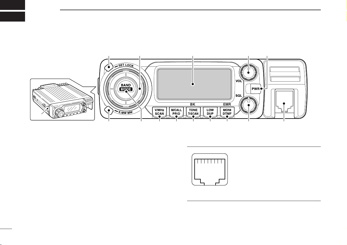
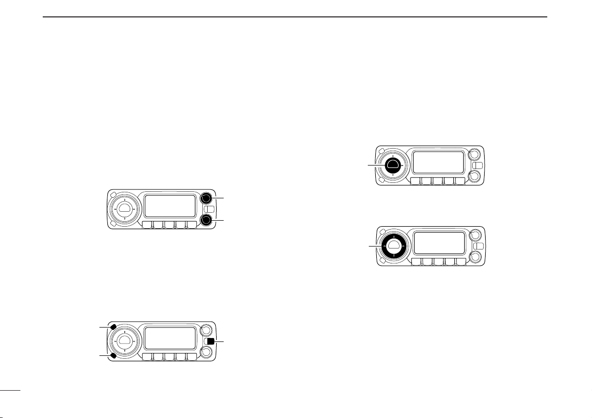
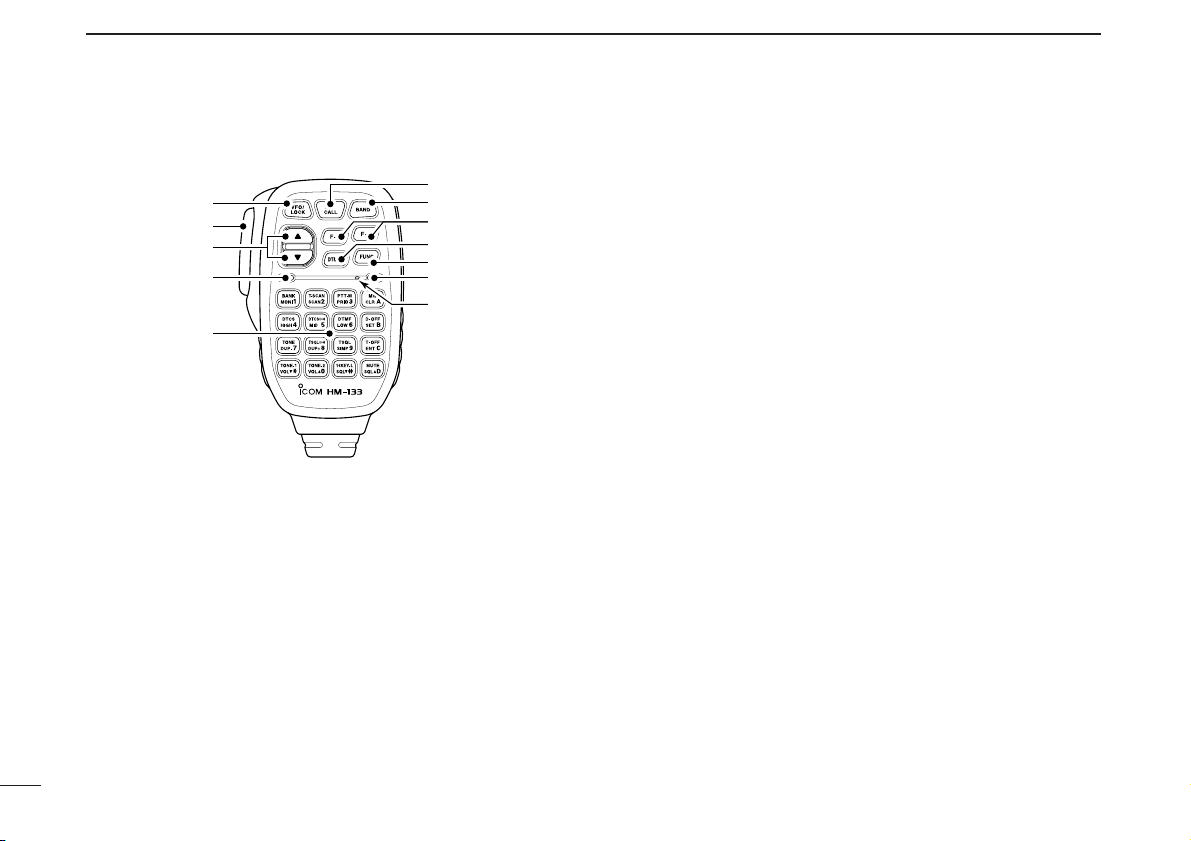
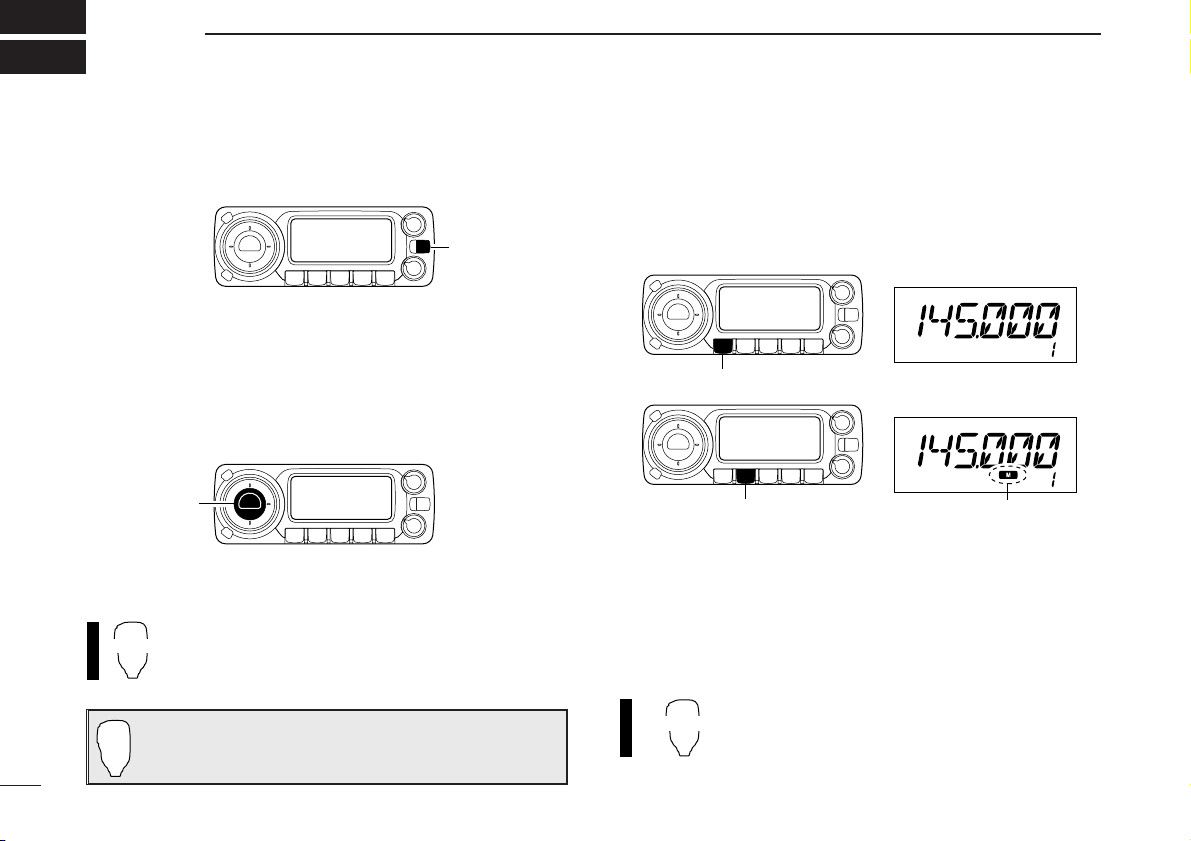
■ Front panel—controller
qSET•LOCK SWITCH [SET•LOCK]
➥ Enters set mode when pushed. (p. 80)
➥ Switches the lock function ON and OFF when pushed
and held for 1 sec. (p. 14)
wTUNING DIAL [DIAL]
Selects the operating frequency (p. 12), memory channel
(p. 28), the setting of the set mode item and the scanning
direction (p. 43).
eVOLUME CONTROL [VOL] (p. 16)
Adjusts the audio level.
rPOWER SWITCH [PWR]
Turns power ON and OFF when pushed and held for
1 sec.
tMICROPHONE CONNECTOR
Connects the supplied or an optional microphone.
q +8 V DC output (Max. 10 mA)
w Channel up/down
e 8V control IN
r PTT
t GND (microphone ground)
y MIC (microphone input)
u GND
i Data IN
ySQUELCH CONTROL [SQL]
Varies the squelch level. (p. 16)
• The RF attenuator activates and increases the attenuation when
rotated clockwise to the center position and further. (p. 17)
q
i
Front panel view
q w Function display (p. 3) e r
t
yuio!0!1!2!3
!4
1
PANEL DESCRIPTION
1
Page 19

2
1
PANEL DESCRIPTION
1
uMONITOR•DTMF•EMR SWITCH [MONI•DTMF•EMR]
➥ Push to switch the monitor function ON and OFF. (p. 16)
❍ While in the analog (FM) mode operation
➥ Turns DTMF memory encoder ON and OFF when
pushed and held for 1 sec. (p. 51)
❍ While in the digital (DV) mode operation
➥ Push and hold to turn the EMR function ON and OFF.
(p. 67)
iOUTPUT POWER•DUPLEX SWITCH [LOW•DUP]
➥ Each push changes the output power selection. (p. 19)
➥ Push and hold for 1 sec. to select DUP–, DUP+ and
simplex operation. (p. 21)
oTONE•TONE SCAN•BREAK-IN SWITCH
[TONE•T-SCAN•BK]
❍ While in the analog (FM) mode operation
➥ Each push selects a tone function. (pgs. 21, 55)
• Subaudible tone encoder, pocket beep (CTCSS), tone
squelch, pocket beep (DTCS), DTCS squelch or tone function OFF can be selected.
➥
Push and hold for 1 sec. to start the tone scan. (p. 59)
❍ While in the digital (DV) mode operation
➥ Each push selects a digital squelch function. (pgs. 68,
69)
• Pocket beep (DSQL), digital call sign squelch, pocket beep
(CSQL), digital code squelch or digital squelch function
OFF can be selected.
➥ Push and hold for 1 sec. to turn the break-in function
ON or OFF. (p. 67)
!0MEMORY/CALL•PRIORITY SWITCH [M/CALL•PRIO]
➥ Push to select and toggle memory, call and weather
channel* modes. (pgs. 11, 28, 40, 99)
*Weather channels are available for USA version only.
➥ Starts priority watch when pushed and held for 1 sec.
(p. 50)
!1VFO/MHz TUNING•SCAN SWITCH [V/MHz•SCAN]
➥ Selects and toggles VFO mode and 1 MHz (or 10 MHz
for some versions) tuning when pushed. (p. 11)
➥ Starts scan when pushed and held for 1 sec. (p. 43)
• Cancels a scan when pushed during scan.
!2BAND•MODE SWITCH [BAND•MODE]
➥ While VFO operation, push to select the operating fre-
quency band. (p. 11)
➥ While call channel operation, push to select the call
channel 1or 2 during call channel operation. (p. 40)
➥ While memory channel operation, push to select mem-
ory bank condition. (p. 37)
➥ Push and hold for 1 sec. and rotate [DIAL] to select the
operating mode. (p. 15)
!3MEMORY WRITE SWITCH [S.MW•MW] (pgs. 29, 41, 45)
➥ Selects a memory channel for programming when
pushed.
➥ Programs the selected memory channel when pushed
and held for 1 sec.
!4CONTROLLER RELEASE LATCH
While pushing this latch, slide the controller to the left to
remove it.
Page 20

3
1
PANEL DESCRIPTION
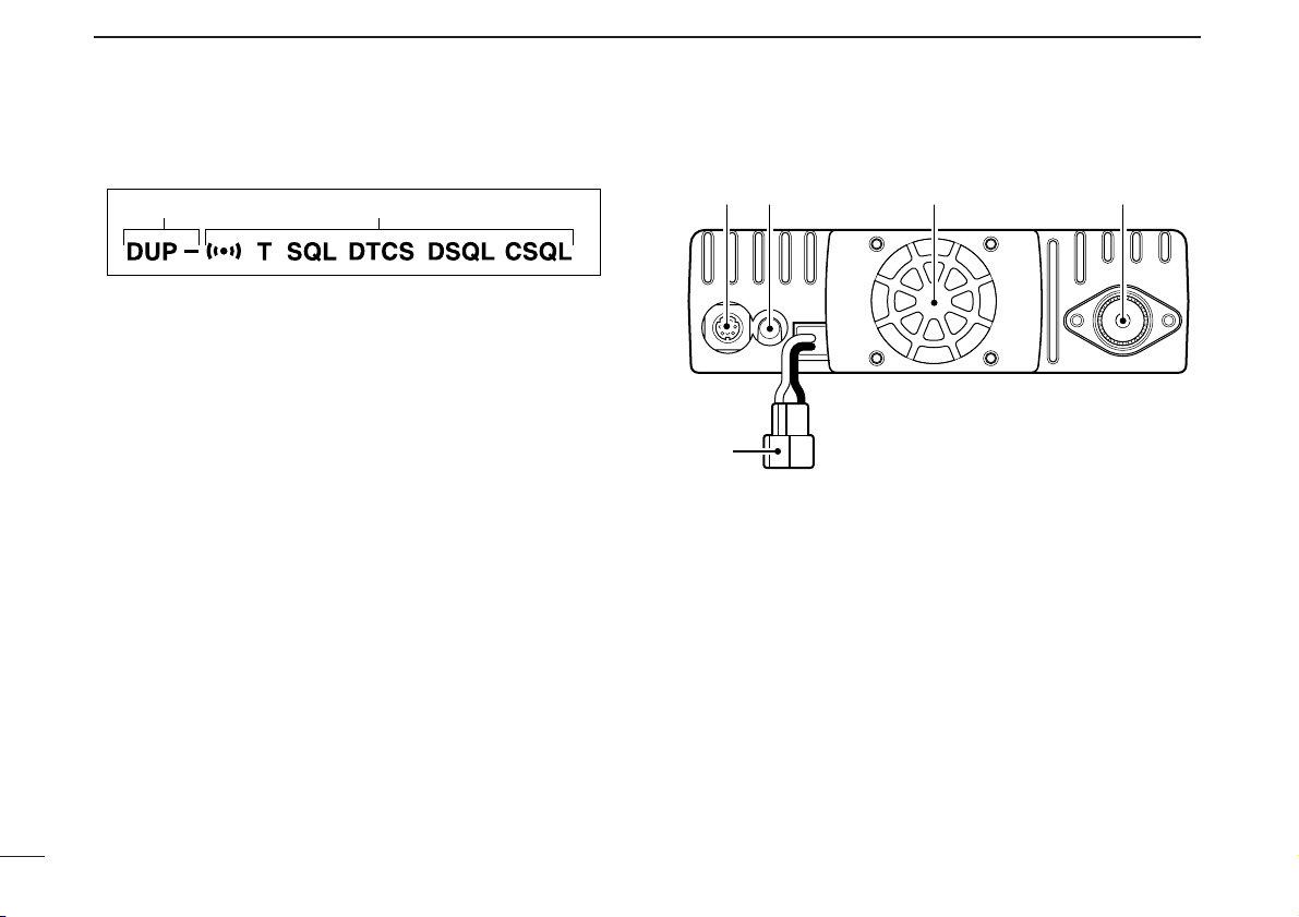
■ Function display
qTRANSMIT INDICATOR
➥ Appears while transmitting. (p. 18)
➥ Blinks while transmitting with the one-touch PTT func-
tion. (p. 19)
wFREQUENCY READOUT
Shows the operating frequency, channel names, set mode
contents, call signs, message, and etc.
• Frequency decimal point blinks while scanning. (p. 43)
•“d” appears in place of the 1st digit while the DTMF memory
function is in use. (p. 51)
eS/RF INDICATORS
➥ Shows the relative signal strength while receiving sig-
nals. (p. 16)
➥ Shows the output power level while transmitting. (p. 19)
rBUSY INDICATOR
➥ Appears when a signal is being received or the squelch
is open. (p. 16)
➥ Blinks while the monitor function is activated. (p. 16)
!4
!5
!7 !6
!3
!0
uy o
e
w
q
t i
r
!1 !2
Page 21

4
1
PANEL DESCRIPTION
1
tOUTPUT POWER INDICATORS (p. 19)
➥ “LOW” appears when low output power is selected.
➥ “MID” appears when middle output power is selected.
➥ No indicator appears when high output power is se-
lected.
yMODE INDICATORS (p. 15)
➥ “AM” appears while in the AM mode operation.
➥ “NAR” appears while in the FM/AM narrow mode oper-
ation.
➥ “DV” appears while in the digital mode operation.
➥ No indication appears while in the FM mode operation.
• Blinking all indication indicates the FM mode selection while
setting.
uDIGITALMESSAGE INDICATOR (p. 76)
Blinks when a digital message is received.
• The indication disappears when any key is pushed.
iSQUELCH ATTENUATOR INDICATOR (p. 17)
Appears when the squelch attenuator function is activated.
• The attenuator can be switched OFF in initial set mode. (p. 96)
oMEMORY INDICATOR (pgs. 11, 28)
Appears when memory mode is selected.
!0SKIP INDICATORS (p. 47)
➥ “~” appears when the displayed memory channel is
specified as a skip channel.
➥ “P ~” appears when the displayed frequency is spec-
ified as a program skip frequency.
!1MEMORY CHANNEL NUMBER INDICATORS
➥ Shows the selected memory channel number. (p. 28)
➥ Shows the selected bank initial. (p. 37)
➥ “C” appears when the call channel is selected. (p. 40)
➥ “L” appears when the lock function is activated. (p. 14)
!2PRIORITY INDICATOR (p. 50)
Appears while priority watch is activated; blinks while the
watch is paused.
!3WEATHER ALERT INDICA T OR (p. 99)
Appears when the weather alert function is activated.
•The either alert function is available with the USA version only.
!4AUDIO MUTE INDICATOR (p. 18)
Appears when the audio mute function is activated.
• The mute can only be switched ON and OFF from the HM-133
only.
!5AUTO POWER-OFF INDICATOR (p. 95)
Appears while the auto power OFF function is in use.
Page 22
5
1
PANEL DESCRIPTION
!6TONE/DIGITAL SQUELCH INDICATORS
❍ While in the analog (FM) mode operation
➥ “T” appears while the subaudible tone encoder is in
use. (p. 21)
➥ “T SQL” appears while the tone squelch function is in
use. (p. 55)
➥ “DTCS” appears while the DTCS squelch function is
in use. (p. 55)
➥ “S” appears with the “T SQL” or “DTCS” indicator
while the pocket beep function
(with CTCSS or DTCS)
is in use. (p. 55)
❍ While in the digital (DV) mode operation
➥ “DSQL” appears while the digital call sign squelch
function is in use. (p. 69)
➥ “CSQL” appears while the digital code squelch func-
tion is in use. (p. 69)
➥ “S” appears with the “DSQL” or “CSQL” indicator
while the pocket beep function
(with DSQL or CSQL)
is in use. (p. 68)
!7DUPLEX INDICATORS (p. 21)
“DUP” appears when plus duplex, “DUP –” appears when
minus duplex (repeater) operation is selected.
■ Rear Panel
qDATA SOCKET [DATA]
Connects a TNC (Terminal Node Controller), etc. for data
communications.
• See p. 6 for connection information.
wEXTERNAL SPEAKER JACK [SP]
Connects an 8 Ω speaker.
• Audio output power is more than 2.0 W.
eCOOLING FAN
Rotates while transmitting.
Also rotates while receiving depending on the setting in initial set mode. (p. 95)
!7 !6
wre
q
t
Page 23
6
1
PANEL DESCRIPTION
1
rANTENNA CONNECTOR [ANT]
Connects a 50 Ω antenna with a PL-259 connector and a
50 Ω coaxial cable.
tPOWER RECEPTACLE [DC13.8V]
Accepts 13.8 V DC ±15% with the supplied DC power
cable.
NOTE: DO NOT use a cigarette lighter socket as a
power source when operating in a vehicle. The plug
may cause voltage drops and ignition noise may be superimposed onto transmit or receive audio.
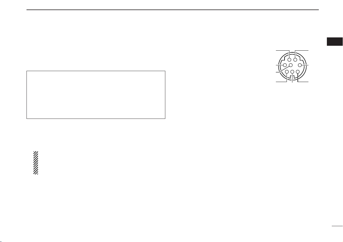
DDATA socket Pin assignment
qDATA IN
Input terminal for data transmit.
See p. 100 for details on how to
toggle data speed between
1200 (AFSK) and 9600 bps
(G3RUH, GMSK).
wGND
Common ground for DATA IN,
DATA OUT and AF OUT.
ePTT P
PTT terminal for packet operation only. Connect ground to
transmit data.
rRS232 OUT
Data out terminal for RS232 connection (GPS operation).
tDATA OUT
Data out terminal for 9600 bps operation only.
yAF OUT
Data out terminal for 1200 bps operation only.
uRS232 IN
Input terminal for RS232 input.
iP SQL
Becomes high (+5 V) when the transceiver receives a signal which opens the squelch.
•To avoid unnecessary TNC transmission, connect squelch to the
TNC to inhibit transmission when receiving signals.
• Keep audio output at a normal level, otherwise a “P SQL” signal
will not be output.
ANTENNA INFORMATION
For radio communications, the antenna is of critical importance, to maximize your output power and receiver sensitivity. The transceiver accepts a 50 Ω antenna and less
than 1:1.5 of Voltage Standing Wave Ratio (VSWR). High
SWR values not only may damage the transceiver but also
lead to TVI or BCI problems.
q
e
r
y
u
Rear panel view
w
t
i
Page 24
7
1
PANEL DESCRIPTION
■ Microphone (HM-133*)
qVFO/LOCK SWITCH [VFO/LOCK]
➥ Push to select VFO mode. (p. 11)
➥ Push and hold for 1 sec. to switch the lock function ON
and OFF. (p. 14)
wPTT SWITCH
➥ Push and hold to transmit; release to receive.
➥ Switches between transmitting and receiving while the
one-touch PTT function is in use. (p. 19)
eUP/DOWN SWITCHES [YY]/[ZZ]
➥ Push either switch to change operating frequency,
memory channel, set mode setting, etc.
(pgs. 12, 28, 80)
➥ Push and hold either switch for 1 sec. to start scanning.
(p. 44)
rACTIVITY INDICATOR
➥ Lights red while any key, except [FUNC] and [DTMF-S],
is pushed, or while transmitting.
➥ Lights green while the one-touch PTT function is in use.
tKEYPAD (pgs. 8, 9)
yFUNCTION INDICATOR
➥ Lights orange while [FUNC] is activated—indicates the
secondary function of switches can be accessed.
➥ Lights green when [DTMF-S] is activated—DTMF sig-
nals can be transmitted with the keypad.
u2nd FUNCTION SWITCH [FUNC]
iDTMF SELECT SWITCH [DTMF-S] (p. 53)
oFUNCTION SWITCHES [F-1]/[F-2] (p. 103)
Program and recall your desired transceiver conditions.
!0BAND SWITCH [BAND]
➥ Push to enter the band selection mode and then push
[YY]/[ZZ] to select the frequency band. (p. 11)
➥ Push and hold for 1 sec. and then push [YY]/[ZZ] to se-
lect the operating mode. (p. 15)
!1MEMORY/CALL SWITCH [MR/CALL]
➥ Push to select memory mode. (p. 11)
➥ Push and hold for 1 sec. to select call channel. (p. 40)
Mic element
q
e
r
t
w
y
u
i
o
!0
!1
*
A different microphone
may be supplied depending on version.
Page 25
■ Microphone keypad
8
1
PANEL DESCRIPTION
1
KEY FUNCTION SECONDARY FUNCTION ( +key) OTHER FUNCTIONS
Switches between opening and closing the
squelch. (p. 16)
Starts and stops scanning. (p. 43)
Starts and stops priority watch. (p. 50)
Selects high output power. (p. 19)
Selects mid. output power. (p. 19)
Selects low output power (p. 19)
Selects minus duplex operation. (p. 22)
Selects plus duplex operation. (p. 22)
Selects simplex operation. (p. 22)
Increases audio output level. (p. 16)
In memory mode enters bank selecting
condition. (p. 37)
Starts and stops tone scanning. (p. 59)
Turns the one-touch PTT function ON and
OFF. (p. 19)
Turns the DTCS squelch ON. (p. 58)
Turns the DTCS pocket beep function ON.
(p. 56)
Turns the DTMF memory encoder function
ON. (p. 53)
Turns the subaudible tone encoder ON.
(p. 22)
Turns the CTCSS pocket beep function
ON. (p. 56)
Turns the tone squelch function ON.
(p. 58)
Sends a 1750 Hz tone signal while pushing
and holding. (p. 25)
After pushing :
Transmits the appropriate
DTMF code. (pgs. 25, 53)
When the DTMF memory encoder is activated, push [0] to
[9] to transmit the appropriate
DTMF memory contents.
(p. 53)
Page 26
9
1
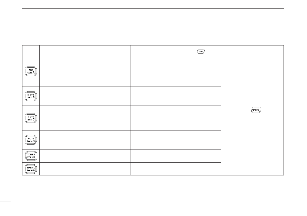
PANEL DESCRIPTION
➥ Cancels frequency entry. (p. 12)
➥ Cancels the scan or priority watch.
(pgs. 43, 50)
➥ Exit set mode. (p. 80)
➥ Enters set mode (p. 80)
➥ Advances the set mode selection order
after entering set mode. (p. 80)
➥ Sets the keypad for numeral input.
(p. 12)
➥ Reverses the set mode selection order
after entering set mode. (p. 80)
Adjusts the squelch level increments.
(p. 16)
Decreases audio output level. (p. 16)
Adjusts the squelch level decrement.
(p. 16)
➥ Selects a memory channel for program-
ming. (p. 30)
➥ Advances the memory channel number
when continuously pushed after programming is completed. (p. 30)
DTMF memory encoder function OFF.
(p. 53)
Turns the subaudible tone encoder, pocket
beep or CTCSS/DTCS tone squelch OFF.
(pgs. 22, 56)
Mutes the audio. (p. 18)
• Mute function is released when any operation is performed.
Sends a 1750 Hz tone signal for 0.5 sec.
(p. 25)
Locks the digit keys on the keypad (including the A to D, # and M keys). (p. 14)
After pushing :
Transmits the appropriate
DTMF code. (pgs. 25, 53)
KEY FUNCTION SECONDARY FUNCTION ( +key) OTHER FUNCTIONS
Page 27
10
1
PANEL DESCRIPTION
1
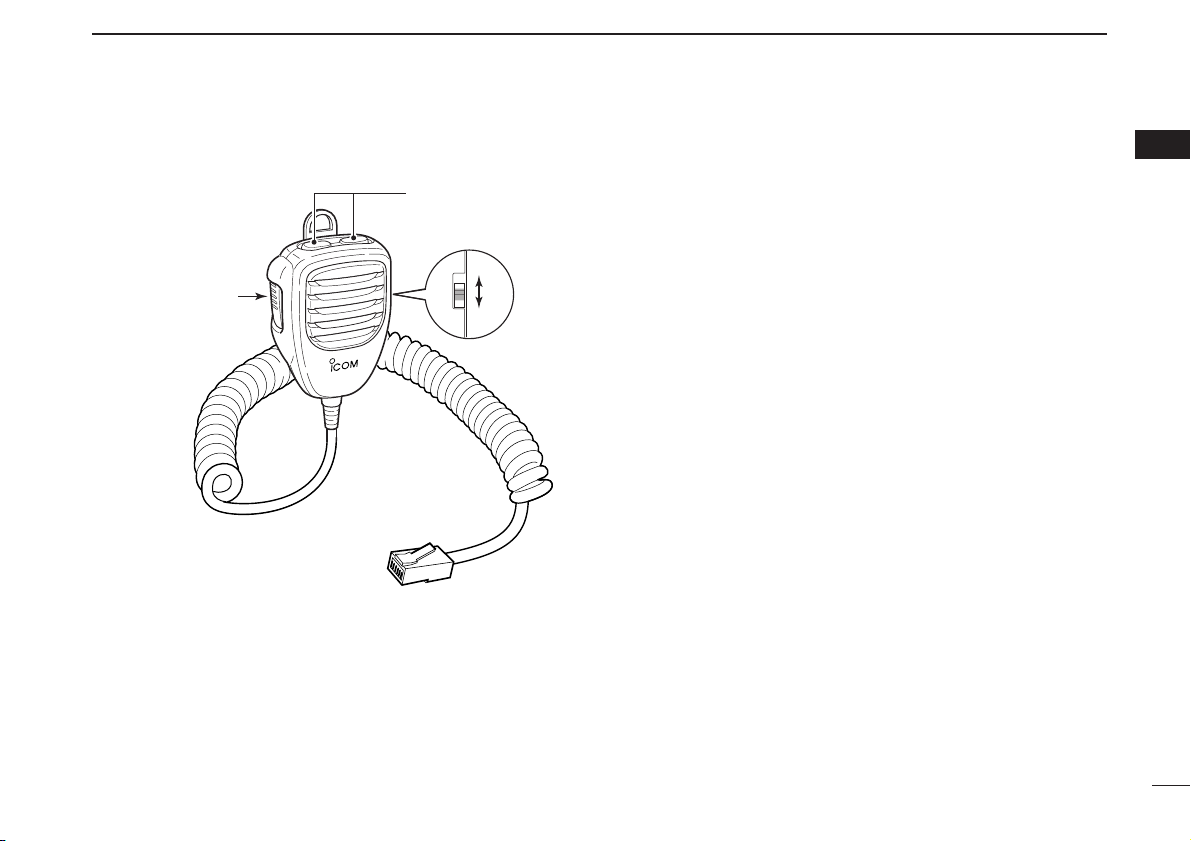
qPTT SWITCH
Push and hold to transmit; release to receive.
wUP/DOWN SWITCHES [UP]/[DN]
➥ Push either switch to change operating frequency,
memory channel, set mode setting, etc.
(pgs. 12, 28, 80)
➥ Push and hold either switch for 1 sec. to start scanning.
(p. 44)
eUP/DN LOCK SWITCH
Slide to toggle [UP]/[DN] switches function ON and OFF.
w
q
ON
OFF
e
• HM-118N
■ Optional Microphone (HM-118N)
Page 28
11
SETTING A FREQUENCY
2
■ Preparation
D Turning power ON/OFF
➥ Push and hold [PWR] for 1 sec. to turn power ON and OFF.
D Operating frequency band selection
The ID-800H has 2 m and 70 cm bands for transmission and
reception. In addition, extra frequency bands 127, 220, 350,
500 and 900 MHz bands are available for wide-band receiver
capability (except Taiwan and Korean version).
➥ Push [BAND•MODE] and rotate [DIAL], then push
[BAND•MODE] to select the desired frequency band.
➥ Push [BAND] and [YY]/[ZZ], then push [BAND]
to select the desired band.
D VFO and memory modes
The transceiver has 2 basic operating modes: VFO mode and
memory mode. Select VFO mode first to set an operating frequency.
➥ Push [V/MHz•SCAN] to select VFO mode.
• When VFO mode is already selected, the digit below 10 MHz
(the digit below 1 MHz or 100 kHz disappear depending on versions) disappear. In this case, push [V/MHz•SCAN] again (or
twice or 3 times depending on version).
➥ Push [M/CALL•PRIO] to select memory mode.
•“!” indicator appears when memory mode is selected.
➥ Push [VFO/LOCK] to select VFO mode.
➥ Push [MR/CALL] to select memory mode.
VFO/LOCK
[V/MHz•SCAN]
[M/CALL•PRIO] Appears
BAND
[BAND•MODE]
[PWR]
Note that in this manual, sections beginning with a microphone icon (as above), designate operation via the HM-133
microphone.
Page 29
12
2
SETTING A FREQUENCY
2
■ Using the tuning dial
qRotate [DIAL] to set the frequency.
• If VFO mode is not selected, push [V/MHz•SCAN] to select VFO
mode.
• The frequency changes in the selected tuning steps. (p. 13)
w
To change the frequency in 1 MHz (10 MHz for some versions)
steps, push [V/MHz•SCAN], then rotate [DIAL].
• Pushing and holding [V/MHz•SCAN] for 1 sec. starts scan func-
tion. If scan starts, push [V/MHz•SCAN] again to cancel it.
■ Using the [YY]/[ZZ] keys
➥ Push [YY] or [ZZ] to select the desired frequency.
• Pushing and holding [YY]/[ZZ] for 1 sec. activates a
scan. If scan starts, push [YY]/[ZZ] or [
CLR
A(MW)] to
cancel it.
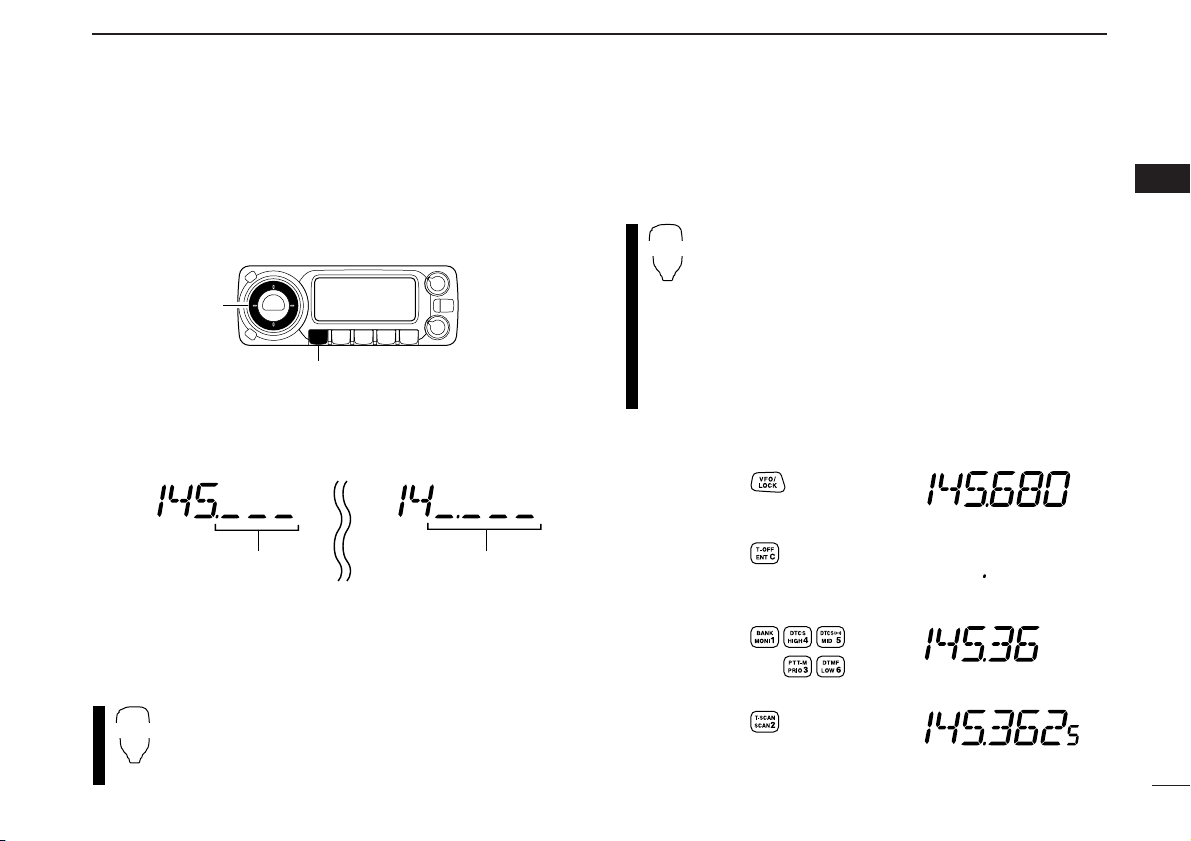
■ Using the keypad
The frequency can be directly set via numeral keys on the microphone.
z Push [VFO/LOCK] to select VFO mode, if nec-
essary.
x Push [
ENT
C(T-OFF)] to activate the keypad for
digit input.
c Push 6 keys to input a frequency.
• When a digit is mistakenly input, push [
ENT
C(T-OFF)]
to clear the input, then repeat input from the 1st digit.
• Pushing [
CLR
A(MW)] clears input digits and retrieves
the frequency.
Push
Push
Push
Push
[EXAMPLE]: Setting frequency to 145.3625 MHz.
ENT
C
YZ
While 1 MHz tuning step is
selected, the digit below
100 kHz disappear.
While 10 MHz tuning step
is selected, the digit below
1 MHz disappear.
[DIAL]
[V/MHz•SCAN]
Page 30
13
2
SETTING A FREQUENCY
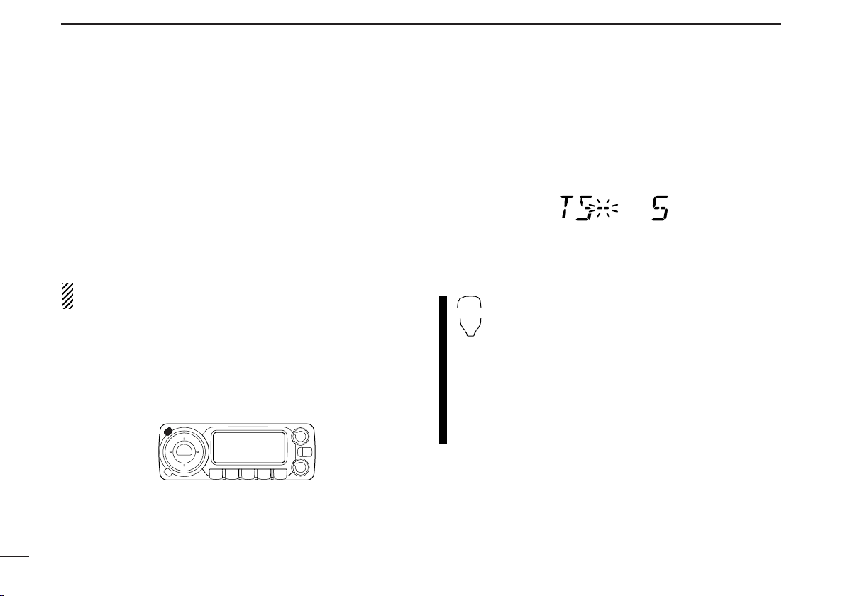
■ Tuning step selection
[
Tuning steps are the minimum frequency change increments
when you rotate [DIAL] or push [YY]/[Z] on the microphone.
Independent tuning step for each frequency bands can be set
for individual tuning convenience. The following tuning steps
are available.
•5kHz • 10 kHz • 12.5 kHz • 15 kHz
•20kHz •25kHz • 30 kHz • 50 kHz
• 100 kHz • 200 kHz
NOTE: For convenience, select a tuning step that matches
the frequency intervals of repeaters in your area.
q Push [BAND•MODE] and rotate [DIAL], then push
[BAND•MODE] to select the desired frequency band.
• Push [V/MHz•SCAN] to select VFO mode, if necessary.
wPush [SET•LOCK] to enter set mode.
• Rotate [DIAL] to select “SET,” if “CALLS” or “MESSAG” is dis-
played.
ePush [SET•LOCK] or [S.MW•MW] several times until “TS”
appears as shown below.
rRotate [DIAL] to select the desired tuning step.
tPush any key below the display to exit set mode.
z Push [BAND] and [YY]/[ZZ], then push [BAND] to
select the desired band.
• Push [VFO/LOCK] to VFO mode, if necessary.
x Push [
SET
B(D-OFF)] to enter set mode.
• Push [YY] or [ZZ] to select “SET,” if necessary.
c Push [
SET
B(D-OFF)] or [
ENT
C(T-OFF)] several
times until “TS” appears.
v Push [YY] or [ZZ] to select the desired tuning
step.
b Push [
CLR
A(MW)] to exit set mode.
SET
B
[SET•LOCK]
Page 31

14
2
SETTING A FREQUENCY
2
■ Lock functions
To prevent accidental frequency changes and unnecessary
function access, use the lock function. The transceiver has 2
different lock functions.
D Frequency lock
This function locks [DIAL] and switches electronically and
can be used together with the microphone lock function.
➥ Push and hold [SET•LOCK] for 1 sec. to turn the lock func-
tion ON and OFF.
• [PTT], [MONI•DTMF] (monitor function only), [VOL] and [SQL]
can be used while the channel lock function is in use. Also,
TONE-1, TONE-2, DTMF tones or DTMF memory contents can
be transmitted from the microphone.
➥ Push and hold [VFO/LOCK] for 1 sec. to
switch the lock function ON and OFF.
D Microphone keypad lock
This function locks the microphone keypad.
➥ Push [FUNC] then [
SQL
ZZ
#(16KEY-L)] to
switch the microphone keypad lock function
ON and OFF.
• [PTT], [VFO/LOCK], [MR/CALL], [BAND], [YY],
[ZZ], [F-1], [F-2] and [FUNC] on the microphone
can be used.
• All switches on the transceiver can be used.
16KEY-L
VFO/LOCK
[SET•LOCK]
“L” appears
Page 32

15
BASIC OPERATION
3
■ Mode selection
The ID-800H has several operating modes, FM/FM narrow
modes, DV mode and AM/AM narrow modes (AM mode is reception only) are available. Typically, AM mode is used for the
air band (118–135.995 MHz).
qSelect the desired frequency band in VFO mode, or the de-
sired memory channel.
wPush and hold [BAND•MODE] for 1 sec. then rotate
[DIAL] to select the desired operating mode.
•“NAR” (FM narrow), “AM,” “NAR AM” and “DV” appears in sequence.
• All indications blink for FM mode selection and no indication
stands for FM mode operation.
• Mode indication while selection
• Mode indication while operation
z Push [BAND] or [MR/CALL] to select the de-
sired frequency band or memory channel.
x Push and hold
[BAND] for 1 sec. then push
[YY]/[ZZ] to select the desired operating mode.
•“NAR,” “AM,” “NAR AM” and “DV” appears in sequence.
• All indications blink for FM mode selection and no indi-
cation s
tands for FM mode.
NOTE: Digital (DV) mode operation is described at section
11. See p. 60 for details.
BAND
FM narrow mode AM narrow mode
DV modeFM mode AM mode
FM narrow mode AM narrow mode
DV mode
FM mode
AM mode
Blinks[BAND•MODE] [DIAL]
Page 33

16
3
BASIC OPERATION
3
■ Receiving
qSet the audio level.
➥ Push [MONI•DTMF] to open the squelch.
➥ Rotate [VOL] to adjust the audio level.
➥ Push [MONI•DTMF] to close the squelch.
wSet the squelch level.
➥ Rotate [SQL] fully counterclockwise in advance, then
rotate [SQL] clockwise until the noise just disappears.
• When interference is received, rotate [SQL] clockwise again
for attenuator operation. (p. 17)
eSet the operating frequency. (pgs. 11, 12)
rWhen receiving a signal on the set frequency, squelch
opens and the transceiver emits audio.
• “BUSY” appears and the S/RF
indicator shows the relative
signal strength for the received signal.
✔
CONVENIENT!
The audio and squelch level can also be adjusted
with [
VOL
YY
(TONE-1)]/[
VOL
ZZ
0(TONE-2)] and
[
SQL
YY
D(MUTE)]/[
SQL
ZZ
#(16KEY-L)], respectively.
• “VOL” for audio or “SQL” for squelch appears during set.
■ Monitor function
This function is used to listen to weak signals without disturbing the squelch setting.
➥ Push [MONI•DTMF] to open the squelch.
• “BUSY” blinks.
• Push [MONI•DTMF] again to cancel the function.
➥ Push [
MONI
1(BANK)] to open the squelch.
• Push [
MONI
1(BANK)] again to cancel the function.
NOTE: When [SQL] adjustment is set too far clockwise,
(12–17 o’clock position) the squelch attenuator is activated. To monitor weak signals on the operating frequency,
deactivate the squelch attenuator function. See p. 17 for
details.
MONI
1
[MONI•DTMF] Blinks
Show set level
SQLY/Z
D/#
VOLY/Z
M/0
Appears when receiving a signal
Page 34

17
3
BASIC OPERATION
■ Squelch attenuator
The transceiver has an RF attenuator related to the squelch
level setting. Approx. 10 dB attenuation is obtained at maximum setting.
The squelch attenuator allows you to set a minimum signal
level needed to open the squelch. The attenuator function can
be deactivated in initial set mode.
➥ Rotate [SQL] clockwise past the 12 o’clock position to ac-
tivate the squelch attenuator.
• Attenuation level can be adjusted up to 10 dB (approx.) between
12 o’clock and fully clockwise position.
• When setting the squelch from the microphone, a level greater
than ‘19’ activates the squelch attenuator.
NOTE: The squelch attenuator functions even when the
monitor function is in use. Thus set [SQL] control within 10
to 12 o’clock position is recommended when using the
monitor function.
D Squelch attenuator setting
qTurn the transceiver power OFF.
wWhile pushing
[SET•LOCK],
turn the power ON to enter ini-
tial set mode.
ePush
[SET•LOCK] or [S.MW•MW] to select “ATT” (squelch
attenuator) item.
rRotate [DIAL] to toggle the function ON and OFF.
• Select “OF” to deactivate the squelch attenuator function.
t Push [PWR] to exit initial set mode.
[PWR]
[SET•LOCK]
USING
INITIAL SET MODE
Squelch is
open.
Squelch
attenuator
Squelch
threshold
Shallow Deep
Noise squelch
Page 35

18
3
BASIC OPERATION
3
■ Audio mute function
This function temporarily mutes the audio without disturbing
the volume setting.
➥ Push [FUNC] then [
SQL
YY
D(MUTE)] to mute
audio signals.
• The audio mute indicator, “ ” appears.
• Push [
CLR
A(MW)] (or any other key) to cancel the
function.
■ Transmitting
NOTE: To prevent interference, listen on the channel be-
fore transmitting by pushing [MONI•DTMF] on the front
panel or [
MONI
1(BANK)] on the microphone.
qSelect the frequency band. (p. 11)
wSet the operating frequency. (pgs. 11, 12)
• Select output power if desired. See p. 19 for details.
ePush and hold [PTT] to transmit.
•“$” appears.
• The S/RF indicator shows the output power selection.
•Aone-touch PTT function is available. See p. 19 for details.
rSpeak into the microphone using your normal voice level.
• DO NOT hold the microphone too close to your mouth or speak
too loudly. This may distort the signal.
tRelease [PTT] to return to receive.
IMPORTANT! (for 55/50 W transmission):
The ID-800H is equipped with a current detector circuit to
protect the power amplifier circuit from high current flowing.
When a high SWR (Standing wave Ratio) antenna or no antenna is connected, or when the connected power supply’s
voltage includes, the transceiver reduces transmit output
power to 10–20 W (approx.) automatically.
CAUTION: Transmitting without an antenna will damage
the transceiver.
Appears
MUTE
Page 36

■ Selecting output power
The transceiver has 3 output power levels to suit your operating requirements. Low output powers during short-distance
communications may reduce the possibility of interference to
other stations and will reduce current consumption.
➥ Push [LOW•DUP] once or twice to select the output power.
*approx
• The output power can be changed while transmitting.
The microphone can also be used to select output power.
➥ Push [
HIGH
4(DTCS)] for high output power;
[
MID
5(DTCSSS)] for middle output power; and
[
LOW
6(DTMF)] for low output power.
• The output power can be changed via the microphone
during receive only.
■ One-touch PTT function
The PTT switch can be operated as a one-touch PTT switch
(each push toggles between transmit/receive). Using this
function you can transmit without pushing and holding the
PTT switch.
To prevent accidental, continuous transmission with this function, the transceiver has a time-out timer. See p. 94 for details.
z Push [FUNC] then [
PRIO
3(PTT-M)] to turn the
one-touch PTT function ON.
• The activity indicator lights green.
x Push [PTT] to transmit and push again to re-
ceive.
•Abeep sounds when transmission is started and a
long beep sounds when returning to receive.
•“$” blinks when transmitting with the one-touch
PTT function.
c Push [FUNC] then [
PRIO
3(PTT-M)] to turn the
one-touch PTT function OFF.
• The activity indicator goes out.
indicator blinks
PTT-M
HIGH
4
MID
5
LOW
6
19
3
BASIC OPERATION
S/RF INDICATOR
POWER OUTPUT
VHF UHF
55 W 50 W
15 W* 15 W*
5W* 5W*
High:
Mid:
Low:
Page 37

20
4
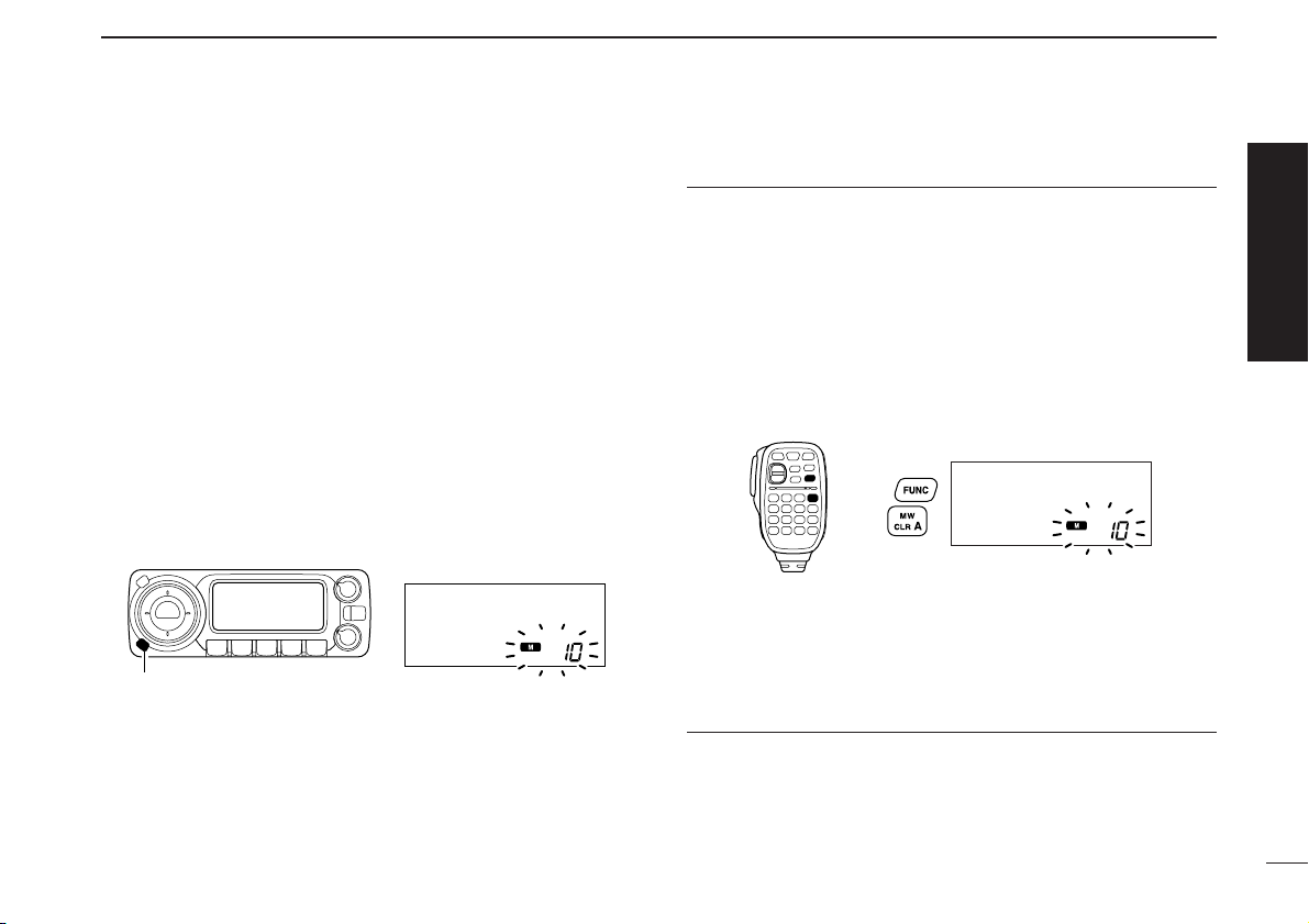
REPEATER OPERATION
4
Repeaters allow you to extend the operational range of your
radio because a repeater has much higher output power than
the typical transceiver.
Normally, a repeater has independent frequencies for each
receiver and transmitter.
A subaudible tone may also be required to access a repeater.
Reference amateur radio hand books and local ham magazines for details of local repeaters such as repeater input/output frequencies and locations.
•Repeater operation flow chart
• The ID-800H USA version has the auto repeater function. Thus the
steps 3 and 4 may not be necessary, depending on the setting.
• Repeater settings can be stored into a memory channel.
Step 3:
Set the duplex (shifting) direction (– duplex or +duplex).
- Set the offset frequency (shifting value), if required.
Step 4:
Set the subaudible tone (repeater tone) encoder function ON.
- Set the subaudible tone frequency, if required.
Step 1:
Set the desired band to operate the repeater.
Step 2:
Set the desired receive frequency (repeater output frequency).
Repeater example;
Receives the 444.540 MHz signal
and the detected audio signals are
transmitted on 449.540 MHz simultaneously.
Station A:
Tx: 444.540 MHz
Rx: 449.540 MHz
Station B:
Tx: 444.540 MHz
Rx: 449.540 MHz
■ General
Page 38

■ Accessing a repeater
q Set the receive frequency (repeater output frequency).
(pgs. 11, 12)
w Push and hold [LOW•DUP] for 1 sec. once or twice, to se-
lect minus duplex or plus duplex.
• “DUP–” or “DUP” appears to indicate the transmit frequency for
minus shift or plus shift, respectively.
• When the auto repeater function is turned ON (available for the
USA version only), steps w and e are not necessary. (p. 27)
e Push [TONE•T-SCAN] several times to turn ON the sub-
audible tone encoder, according to repeater requirements.
• “T” appears
• 88.5 Hz is set as the default; refer to p. 23 for tone frequency
settings.
• When the repeater requires a different tone system, see p. 25.
r Push and hold [PTT] to transmit.
•The displayed frequency automatically changes to the transmit
frequency (repeater input frequency).
• If “OFF” appears, confirm that the offset frequency (p. 26) is set
correctly.
t Release [PTT] to receive.
yPush [MONI•DTMF] to check whether the other station’s
transmit signal can be received directly.
uTo return to simplex operation, push [LOW•DUP] once or
twice, to clear the “DUP–” or “DUP” indicator.
iTo turn OFF the subaudible tone encoder, push [TONE•T-
SCAN] several times until no tone indicators appear.
While transmittingWhile receiving
[TONE•T-SCAN] “T” appears
[LOW•DUP] “DUP–” or “DUP” appears
21
4
REPEATER OPERATION
Page 39

22
4
REPEATER OPERATION
4
z Set the receive frequency (repeater output fre-
quency). (pgs. 11, 12)
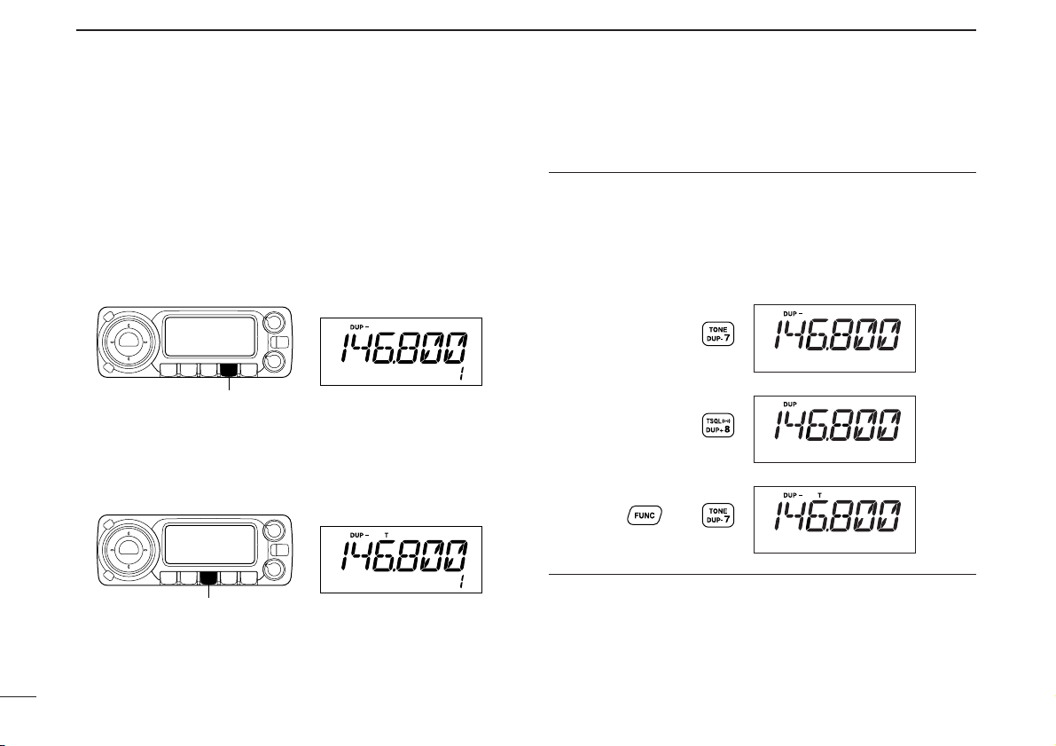
x Push [
DUP
– 7(TONE)] to select minus duplex;
push [
DUP
+ 8(TSQLSS)] to select plus duplex.
c Push [FUNC] then [
DUP
– 7(TONE)] to turn ON
the subaudible tone encoder according to repeater requirements.
• Refer to p. 24 for the tone frequency setting.
• When the repeater requires a different tone system,
see p. 25.
v Push and hold [PTT] to transmit.
b Release [PTT] to receive.
n Push [
MONI
1(BANK)] to check whether the
other station’s transmit signal can be received
directly.
m Push [
SIMP
9(TSQL)] to return to simplex oper-
ation.
• “DUP” or “DUP–” indicator disappears.
, To turn OFF the subaudible tone encoder, push
[FUNC] then [
ENT
C(T-OFF)].
SIMP
9
Push ,
then .
Push
Push
DUP–
7
DUP+
8
Page 40

23
4
REPEATER OPERATION
D Subaudible tones
q Select the frequency band, mode/channel you wish to set
the subaudible tones, such as VFO mode or memory/call
channel.
w Push [SET•LOCK] to enter set mode.
• Rotate [DIAL] to select “SET,” if “CALLS” or “MESSAG” is dis-
played.
e Push [SET•LOCK] or [S.MW•MW] several times until “T”
and “rT” appear; or until “T SQL” and “CT” appear for tone
squelch or pocket beep use.
• When “d” is displayed in place of the 100 MHz digit, cancel the
DTMF memory encoder in advance. (p. 53)
r Rotate [DIAL] to select and set the desired subaudible fre-
quency.
t Push any key below the display to exit set mode.
• Subaudible tone frequency list
(unit: Hz)
NOTE: The subaudible tone encoder frequency can be set
in a memory/call channel temporarily. However, the set frequency is cleared once another memory channel or VFO
mode is selected. To store the tone frequency permanently,
overwrite the channel information.
■ Subaudible tones (Encoder function) [
[SET•LOCK]
“T” and “rT” appears
“TSQL” and “CT” appears
165.5
136.5
107.2
67.0
69.3
71.9
74.4
77.0
79.7
82.5
85.4
88.5
91.5
94.8
97.4
100.0
103.5
110.9
114.8
118.8
123.0
127.3
131.8
141.3
146.2
151.4
156.7
159.8
162.2
167.9
171.3
173.8
177.3
179.9
183.5
186.2
189.9
192.8
196.6
199.5
203.5
206.5
210.7
218.1
225.7
229.1
233.6
241.8
250.3
254.1
Page 41

24
4
REPEATER OPERATION
4
z Set the frequency band, mode/channel you wish
to set the subaudible tones, such as VFO mode
or memory/call channel.
• The subaudible tone frequency is independently programmed into each mode or channel.
x Push [
SET
B(D-OFF)] to enter set mode.
• Push [YY] or [ZZ] to select “SET,” if necessary.
c
Push [
SET
B(D-OFF)] or [
ENT
C(T-OFF)] several
times until “T”
and “rT” appears; or until “T SQL”
and “CT” appears for tone squelch or pocket
beep use.
•
When “d” is displayed in place of the 100 MHz digit,
cancel the DTMF memory encoder in advance. (p. 53)
v Push [YY] or [ZZ] to select and set the desired
subaudible tone frequency.
• Push and hold [YY]/[ZZ] to change the above tones
continuously.
b Push [
CLR
A(MW)] to exit set mode.
Push
SET
B
Page 42

25
4
REPEATER OPERATION
D DTMF tones
➥ Push [DTMF-S], then push the keys of the de-
sired DTMF digits.
• The function indicator lights green.
• 0–9, A–D, M(E) and #(F) are available.
• When “d” is displayed in place of the 100 MHz digit,
cancel the DTMF memory encoder in advance.
(p. 53)
• Push [DTMF-S] again to return the keypad to nor-
mal function control.
✔
For your convenient!
The transceiver has 16 DTMF memory channels for autopatch operation. See p. 51 for details.
D 1750 Hz tone
The microphone has 1750 Hz tone capability, used for ring
tone when calling, etc.
z Push [FUNC].
• The function indicator lights orange.
x Push [MM(TONE-1)] to transmit a 1750 Hz tone
call signal for 0.5 sec.; push and hold
[0(TONE-2)] to transmit a 1750 Hz tone call
signal for an arbitrary period.
• The function indicator goes out automatically.
Push ,
then or .
TONE-1
TONE-2
then push desired keys.
Push ,
DTMF-S
Page 43

26
4
REPEATER OPERATION
4
■ Offset frequency [
When communicating through a repeater, the transmit frequency is shifted from the receive frequency by an amount
determined by the offset frequency.
Independent offset frequencies can be set for each operating
frequency.
qPush [BAND•MODE] and rotate [DIAL], then push
[BAND•MODE] to select the desired frequency band.
wSelect the desired mode/channel you wish to set the offset
frequency, such as VFO mode or memory/call channel.
• The offset frequency can be independently programmed into
each mode or channel.
ePush [SET•LOCK] to enter set mode.
• Rotate [DIAL] to select “SET,” if “CALLS” or “MESSAG” is dis-
played.
rPush [SET•LOCK] or [S.MW•MW] until “DUP” and offset
frequency appear.
tRotate [DIAL] to set the desired offset frequency.
yPush any key (other than [V/MHz•SCAN]) below the dis-
play to exit set mode.
z Push [BAND] and [YY]/[ZZ], then push [BAND]
to select the desired band.
• Enter the desired frequency via the keypad if necessary.
x Select the desired mode/channel you wish to
set the offset frequency, such as VFO mode or
memory/call channel.
• The offset frequency can be independently programmed into each mode or channel.
c Push [
SET
B(D-OFF)] to enter set mode.
• Push [YY] or [ZZ] to select “SET,” if necessary.
v Push [
SET
B(D-OFF)] or [
ENT
C(T-OFF)] until
“DUP” and offset frequency appear.
b Push [YY] or [ZZ] to set the desired offset.
• Direct frequency entry from the keypad is not possible.
n Push [
CLR
A(MW)] to exit set mode.
NOTE: The offset frequency can be set in a memory/call
channel temporarily. However, the set frequency is cleared
once another memory channel or VFO mode is selected.
To store the offset frequency permanently, overwrite the
channel information.
r
[SET•LOCK] “DUP” and offset frequency appea
SET
B
Push
Page 44

27
4
REPEATER OPERATION
■ Auto repeater (USA version only)
The USA version automatically activates the repeater settings
(DUP– or DUP+ and tone encoder ON/OFF) when the operating
frequency falls within the general repeater output frequency
range and inactivate them when outside of the range.
D Setting the auto repeater function ON/OFF
q Push [PWR] to turn power OFF.
w While pushing [SET•LOCK], turn power ON to enter initial
set mode.
e Push [SET•LOCK] or [S.MW•MW] several times until
“RPT” appears as shown above right.
r Rotate [DIAL] to select the auto repeater function from
“R1,” “R2” or OFF.
• “R1”: auto repeater is ON, tone encoder is OFF.
• “R2”: auto repeater is ON, tone encoder is ON.
t Push [PWR] to exit initial set mode.
D Frequency range and offset direction
Auto DUP: ON
Auto tone set: OFF
Auto DUP: ON
Auto tone set: ON
USING
INITIAL SET MODE
[PWR]
[SET•LOCK]
Frequency range Duplex direction
145.200–145.495 MHz
“DUP–” appears
146.610–146.995 MHz
147.000–147.395 MHz “DUP” appears
442.000–444.995 MHz “DUP” appears
447.000–449.995 MHz “DUP–” appears
Page 45

28
5
MEMORY OPERATION
4
5
■ General description
The transceiver has 512 memory channels including 10 scan
edge memory channels (5 pairs), and 2 call channels. Each of
these channels can be individually programmed with operating frequency (pgs. 11, 12), duplex direction (p. 21) and offset (p. 26), subaudible tone encoder or tone squelch and its
tone frequency (pgs. 21, 23, 55, 56) and skip information
(p. 47).
In addition, a total of 10 memory banks, A to J, are available
for usage by group, etc.
■ Memory channel selection
D Using the tuning dial
q Push [M/CALL•PRIO] several times to select memory
mode.
•“!” indicator appears
w Rotate [DIAL] to select the desired memory channel.
• Programmed memory channels only can be selected.
D Using the [YY]/[ZZ] keys
z Push [MR/CALL] to select memory mode.
x Push [YY] or [ZZ] to select and set the desired
memory channel.
• Pushing and holding [YY]/[ZZ] for 1 sec. activates a
scan.
• If scan is activated, push [YY]/[ZZ] again or push
[
CLR
A(MW)] to stop it.
D Using the keypad
z Push [MR/CALL] to select memory mode.
x Push [
ENT
C(T-OFF)] to activate the keypad
for numeral input.
c Push 3 appropriate digit keys to input a chan-
nel number.
• Blank channel can be selected.
• Push only 1 appropriate digit key, [
MONI
1(BANK)], [
SCAN
2(T-SCAN)], [
PRIO
3(PTT-M)],
[
HIGH
4(DTCS)] or [
MID
5(DTCSSS)] then push
[MM(TONE-1)] or [
SQL
ZZ
#(16KEY-L)] to select scan
edge channels. “MM” and “#” can be used for “A”
and “B” respectively.
MR/CALL
MR/CALL
Y/Z
[M/CALL•PRIO] “!” appears
Page 46

29
5
MEMORY OPERATION
■ Programming a memory channel
[EXAMPLE]: Programming 145.870 MHz into memory channel 20 (blank channel) via the controller.
Push
Rotate for setting frequency, etc.
Push .
Rotate
Push for 1 sec. and continue to push
➠
Beep
“
Beep
Beep
Beep
“
“
“
“
“
Beep
“
VFO settings, including the set mode contents such as subaudible tone frequency or offset, can be programmed into a
memory channel.
qSet the desired frequency.
➥ Push [V/MHz•SCAN] to select VFO mode.
➥ Set the frequency using [DIAL].
➥ Set other data (e.g. tone frequency, duplex information,
etc.) if required.
wPush [S.MW•MW].
•“!” indicator and the memory channel number blink.
eRotate [DIAL] to select the memory channel to be pro-
grammed.
• Memory channels not yet programmed are blank.
rPush and hold [S.MW•MW] for 1 sec. to program.
•3 beeps sound
• Memory channel number automatically increases when contin-
uing to push [S.MW•MW] after programming.
✔CONVENIENT
Memory programming can be performed in versatile ways
e.g. memory channel to the same (or different) memory channel, memory channel to the call channel, etc.
Page 47

30
5
MEMORY OPERATION
5
D Programming a memory channel via the microphone
[EXAMPLE]: Programming 145.870 MHz into memory channel 20 (blank channel) via the microphone.
Push 10 times
Beep
“
Beep
“
Beep
Beep
Beep
“
“
“
“
“
Push Push then
Push then for 1 sec. and continue to push
➠
The microphone can also be used to program mem-
ory channels.
z Set the desired frequency in VFO mode.
➥ Push [VFO/LOCK] to select VFO mode.
➥ Set the frequency using the keypad.
➥ Set other data
(e.g. offset frequency, duplex direction, sub-
audible tone encoder ON/OFF and its frequency), if neces-
sary.
x Push [FUNC] then [
CLR
A(MW)] momentarily.
c Push [YY] or [ZZ] to select the memory channel.
•
Direct numeral input cannot be used.
v Push [FUNC], and then push and hold [
CLR
A(MW)] for
1 sec. to program.
➥ 3 beeps may sound and the VFO contents (including
the subaudible tone frequency, etc.) are programmed.
➥ Memory channel number increases when continuing to
push [
CLR
A(MW)] after programming.
MW
Page 48

31
5
MEMORY OPERATION
■
Copying memory contents
This function copies a memory channel’s contents to VFO (or
another memory/call channel). This is useful when searching
for signals around a memory channel frequency and for recalling the offset frequency, subaudible tone frequency etc.
D Memory/call➪VFO
q Select the desired memory or call channel.
➥ Push [M/CALL•PRIO] several times to select memory
mode or call channel, then rotate [DIAL] or push
[BAND•MODE] to select the desired memory or call
channel respectively.
w Push and hold [S.MW•MW] for 1 sec. to transfer the se-
lected memory/call channel contents to the VFO.
• VFO mode is selected automatically.
z Select the memory/call channel to be
transferred.
➥ Push [MR/CALL] to select memory mode,
then select the desired memory channel
via [YY]/[ZZ] or keypad.
➥ Push and hold [MR/CALL] for 1 sec. then
push [BAND] to select the desired call
channel.
x
Push [FUNC], and then push and hold
[
CLR
A(MW)] for 1 sec. to transfer the selected
memory/call channel contents to the VFO.
• VFO mode is selected automatically.
MR/CALL
MW
BAND
[Y]/[Z]
[EXAMPLE]: Transferring memory channel 30 contents to VFO.
Push to select memory mode.
Front panel operation:
HM-133 operation:
Push to select memory mode.
Rotate for selecting memory channel.
Push [Y]/[Z] to select memory channel.
Push for 1 sec.
Push then push for 1 sec.
Page 49

32
5
MEMORY OPERATION
5
D Memory/call➪call/memory
q Select the memory/call channel to be transferred.
➥ Push [M/CALL•PRIO] several times to select memory
mode or call channel, then rotate [DIAL] or push
[BAND•MODE] to select the desired memory or call
channel respectively.
w Push [S.MW•MW] momentarily.
•“!” indicator and “-- -- --” indication blink, and shows VFO con-
ditions.
e Rotate [DIAL] to select the target memory channel.
• “C1” or “C2” blinks when the call channel is selected.
• Scan edge channels, 1A/1B, 2A/2B, 3A/3B, 4A/4B, 5A/5B can
also be selected.
r Push and hold [S.MW•MW] for 1 sec. to transfer the se-
lected memory/call channel contents to the target memory.
• The targeted memory and transferred contents are indicated.
z Select the memory/call channel to be trans-
ferred.
➥ Push [MR/CALL] to select memory mode,
then select the desired memory channel
via [YY]/[ZZ] or keypad.
➥ Push and hold [MR/CALL] for 1 sec. then
push [BAND] to select the desired call
channel.
x
Push [FUNC], then [
CLR
A(MW)] momentarily.
•“!” indicator and “-- -- --” indication blink, and
shows VFO conditions.
c Push [YY]/[ZZ] to select the target memory
channel.
•
“C1” or “C2” blinks when the call channel is selected.
•Scan edge channels can also be selected.
• The keypad cannot be used for the selection.
v Push [FUNC] then push [
CLR
A(MW)] for
1 sec. to transfer the selected memory/call
channel contents to the target channel.
• The targeted channel and transferred contents
are indicated.
MR/CALL
MW
BAND
[Y]/[Z]
[EXAMPLE]: Transferring memory channel 30 contents to channel 31.
Select the target channel.
Push for 1 sec.
Push then push for 1 sec.
Select the memory channel, then push .
Select the memory channel, push then push .
Front panel operation:
HM-133 operation:
Page 50

33
5
MEMORY OPERATION
■ Programming channel names
Each memory channel and the call channel can be programmed with an alphanumeric channel name for easy
recognition and can be indicated independently by channel.
Names can be a maximum of 6 characters— see the table
below for available characters.
q Push [S.MW•MW] momentarily.
•“!” and memory channel number blink.
w Rotate [DIAL] to select the desired memory or call chan-
nel.
e Push [BAND•MODE] to select the memory name pro-
gramming condition.
• Frequency readouts disappear and a cursor blinks.
r Rotate [DIAL] to select the desired character.
• The selected character blinks.
t Push [SET•LOCK] to move the cursor to the right.
y Repeat steps r and t until the desired channel names
are displayed.
u Push and hold [S.MW•MW] for 1 sec. to program the
name and exit the channel name programming condition.
[EXAMPLE]: Programming “CLUB” into memory channel 1.
RotatePush Push
Rotate
Push for 1 sec.
Repeat the
previous
steps.
Beep
Beep
Beep
“
“
“
“
“
Push
(+)
(–)
(=)
(✱)
(5)
(F)
(P)
(Z)
(6)
(G)
(
(/)
(()
(7)
(
H
)
(
Q
)
R
)
())
(8)
(I)
(S)
(9)
(J)
(T)
(|)
(0)
(A)
(K)
(U)
(space)
(2)
(3)
(
(N)
(X)
(4)
D
)
(E)
(O)
(Y)
(1)
(B)
(L)
(V)
(C)
(M)
(W)
Page 51

34
5
MEMORY OPERATION
5
Channel names can also be programmed via the mi-
crophone.
z Push [FUNC] then [
CLR
A(MW)] momentarily.
•“!” and memory channel number blink.
x Push [YY]/[ZZ] to select the memory/call channel to be as-
signed memory names.
c Push [BAND].
• Frequency readouts disappear and a cursor blinks.
v Push [YY]/[ZZ] to select the desired character.
• The selected character blinks.
b Push [
SET
B(D-OFF)] or [
ENT
C(T-OFF)] to move the cur-
sor to left or right, respectively.
n Repeat steps v and b until the desired channel names
are displayed.
m Push [FUNC], and then push and hold [
CLR
A(MW)] for
1 sec. to program the name and exit the channel name
programming condition.
[EXAMPLE]: Programming “CLUB” into memory channel 1.
Push
Repeat the
previous
steps.
Beep
Beep
Beep
“
“
“
“
“
Push to select the channel. Push to select the character
Push or to move the cursor.
Push , then push .
Push , then push for 1 sec.
Page 52

5
MEMORY OPERATION
35
DD
To indicate the channel name [
The channel name indication can be set for independent
memory channels.
q Push [M/CALL•PRIO] to select the memory mode.
w Rotate [DIAL] to select the desired memory channel to be
indicated the channel name.
e Push [SET•LOCK] to enter set mode.
• Rotate [DIAL] to select “SET,” if “CALLS” or “MESSAG” is dis-
played.
r Push [SET•LOCK] or [S.MW•MW] several times to select
“ANM” item.
t Rotate [DIAL] to turn the memory name indication ON.
y Push any key below the display to exit set mode.
NOTE: When no memory name is programmed, the stored
frequency is displayed.
z Push [MR/CALL] to select the memory mode.
x Push [YY] or [ZZ] to select the desired memory
channel to be indicated the channel name.
c Push [
SET
B(D-OFF)] to enter set mode.
• Push [YY] or [ZZ] to select “SET,” if necessary.
v Push [
SET
B(D-OFF)] or [
ENT
C(T-OFF)] until
“ANM” appear.
b Push [YY] or [ZZ] to set the memory name indi-
cation ON and OFF.
n Push [
CLR
A(MW)] to exit set mode.
Push
SET
B
Page 53

5
MEMORY OPERATION
36
5
■ Memory clearing
Contents of programmed memories can be cleared (blanked),
if desired.
q Push [V/MHz•SCAN] to select VFO mode.
w Push [S.MW•MW] momentarily.
•“!” indicator and the memory channel number blink.
e Rotate [DIAL] to select the memory channel to be cleared.
• Memory channels not yet programmed are blank.
r Perform the following operation within 1.5 sec.
- Push [S.MW•MW] momentarily.
- Push and hold [S.MW•MW] for 1 sec.
•3 beep sound, then the contents of the selected memory are
cleared.
•“!” indicator and the channel number blink.
•When clearing the call channel, the current VFO conditions are
re-programmed into the call channel automatically.
t Push [V/MHz•SCAN] to return to VFO mode.
NOTE: BE CAREFUL! — the contents of cleared memo-
ries CANNOT be recalled.
[EXAMPLE]: Clearing memory channel 20.
Push to select VFO.
Rotate for selecting memory channel.
Push .
Push any switch, except .
Push momentarily, then push again for 1 sec.
Beep
Beep
Beep
“
“
“
“
“
Page 54

37
5
MEMORY OPERATION
■ Memory bank selection
The ID-800H has a total of 10 banks (A to J). Each memory
channel, 1 to 500, may be assigned to one of the banks for
easy memory management.
q Push [M/CALL•PRIO] several times to select memory
mode, if desired.
w Push [BAND•MODE] to enter memory bank selection.
• Bank indicator blinks
e Rotate [DIAL] to select the desired bank, A to J.
• Banks that have no programmed contents are skipped.
r Push [BAND•MODE] to select the bank.
•Bank indicator stops blinking.
t Rotate [DIAL] to select the channel in the bank.
• No channel numbers are displayed for memory bank operation.
y To return to regular memory mode, push [BAND• MODE]
twice.
z Push [MR/CALL] to select memory mode, if
desired.
x Push [FUNC] then [
MONI
1(BANK)] to enter
memory bank selection.
• Bank indicator blinks
c Push [YY]/[ZZ] to select the desired bank, A to J.
• Only programmed memory bank can be selected.
v Push [
CLR
A(MW)] to select the bank.
• Bank indicator stops blinking.
b Push [YY]/[ZZ] to select the channel in the bank.
• No channel numbers are displayed for memory
bank operation.
n To return to regular memory mode, push
[FUNC], [
MONI
1(BANK)] then push
[
CLR
A(MW)].
BANK
[Y]/[Z]
[BAND•MODE] Bank indicator blinks
Page 55

38
5
MEMORY OPERATION
5
q Push [M/CALL•PRIO] several times to select memory
mode, then select the desired memory channel via [DIAL].
w Push [SET•LOCK] to enter set mode.
• Rotate [DIAL] to select “SET,” if “CALLS” or “MESSAG” is dis-
played.
e Push [SET•LOCK] or [S.MW•MW] several times until
“BAK” appears.
r Rotate [DIAL] to select the desired bank.
t Push any key below the display to assign the channel to
the bank and exit set mode.
z Push [MR/CALL] then select the desired mem-
ory channel via [YY]/[ZZ] or keypad.
x Push [
SET
B(D-OFF)] to enter set mode.
• Push [YY] or [ZZ] to select “SET,” if necessary.
c Push [
SET
B(D-OFF)] or [
ENT
C(T-OFF)] several
times until “BAK” appears.
v Push [YY]/[ZZ] to select the desired bank.
b Push [
CLR
A(MW)] to assign the channel to the
bank and exit set mode.
SET
B
[SET•LOCK]
■ Memory bank setting [
Page 56

39
5
MEMORY OPERATION
Contents of programmed memory banks can be cleared or
transferred to another bank.
INFORMATION: Even if the memory bank contents are
cleared, the memory channel contents still remain programmed.
q Select the desired bank contents to be transferred or
erased.
➥ Push [M/CALL•PRIO] several times to select memory
mode.
➥ Push [BAND•MODE] then rotate [DIAL] to select the
desired memory bank.
• Bank indicator blinks.
➥ Push [BAND•MODE] to select the bank then rotate
[DIAL] to select the desired contents.
• Bank indicator stops blinking.
w Push [SET•LOCK] to enter set mode.
• Rotate [DIAL] to select “SET,” if “CALLS” or “MESSAG” is dis-
played.
e Push [SET•LOCK] or [S.MW•MW] several times until
“BAK” appears.
• The bank indicator for the selected memory channel is displayed.
rRotate [DIAL] to select the desired bank to receive the
transferred information or erase the bank contents.
• Select “-- --” indication when erasing the contents from the bank.
t Push any key below the display to set the bank and exit
set mode.
y Repeat steps q to t for transferring or erasing an an-
other bank’s contents.
z Select the desired bank contents to be trans-
ferred or erased.
➥ Push [MR/CALL] to select memory mode.
➥ Push [FUNC], [
MONI
1(BANK)] then select
the desired memory bank via [YY]/[ZZ].
➥ Push [
CLR
A(MW)] to select the bank then
select the desired contents via [YY]/[ZZ].
x Push [
SET
B(D-OFF)] to enter set mode.
• Push [YY] or [ZZ] to select “SET,” if necessary.
c Push [
SET
B(D-OFF)] or [
ENT
C(T-OFF)] sev-
eral times until “BAK” appears.
v Push [YY]/[ZZ] to select the desired bank to
transfer or erase.
• Select “-- --” indication when erasing the contents
from the bank.
b Push [
CLR
A(MW)] to set the bank and exit set
mode.
n Repeat steps z to b for transferring or eras-
ing an another bank’s contents.
BANK
[Y]/[Z]
SET
■ Transferring bank contents [
Page 57

40
6
CALL CHANNEL OPERATION
5
6
■ Call channel selection
Call channel is pre-programmed memory channel that can be
accessed by simply pushing call channel button.
➥ Push [M/CALL•PRIO] several times to select the call chan-
nel mode then push [BAND•MODE] to select the desired
call channel.
• “C1” or “C2” appears instead of memory channel number indication.
•
Push [M/CALL•PRIO] several times to select memory mode, or
push [V/MHz•SCAN] to select VFO mode.
➥ Push and hold [MR/CALL] for 1 sec. to select
the call channel mode then push [BAND] to
select the desired call channel in the main
band.
• Push [MR/CALL] to select memory mode, or push
[VFO/LOCK] to select VFO mode.
■ Call channel transferring
q Push [M/CALL•PRIO] several times then push
[BAND•MODE] to select the desired call channel.
• “C1” or “C2” appears.
w Push [S.MW•MW] then rotate [DIAL] to select the mem-
ory channel to receive the transferred information.
•“!” indicator and memory channel number blink.
•To transfer to the VFO, select “-- -- --” with [DIAL] then push.
e Push and hold [S.MW•MW] for 1 sec. to transfer the con-
tents.
z Push and hold [MR/CALL] for 1 sec. then
push [BAND] to select the desired call channel.
x Push [FUNC], [
CLR
A(MW)] momentarily,
then push [YY]/[ZZ] to select the memory
channel to receive the transferred information.
•To transfer to the VFO, push [YY]/[ZZ] to select
“-- -- --”.
c Push [FUNC], and then push and hold
[
CLR
A(MW)] for 1 sec. to transfer the con-
tents.
MR/CALL
MW
BAND
[Y]/[Z]
MR/CALL
[M/CALL•PRIO] “C1” or “C2” appears
✔INFORMATION
When the VFO mode is selected from the call channel, a
small “c” appears instead of
memory channel number.
Page 58

41
6
CALL CHANNEL OPERATION
■ Programming a call channel
Operating frequency, duplex information, subaudible tone information (tone encoder or tone squelch ON/OFF and its frequency) can be programmed into the call channel.
q Set the desired frequency in VFO mode.
➥ Push [V/MHz•SCAN] to select VFO mode.
➥ Set the frequency using [DIAL].
➥ Set other data as desired.
w Push [S.MW•MW] momentarily.
e Rotate [DIAL] to select the desired call channel.
•“!” indicator and “C1” or “C2” blink.
r Push and hold [S.MW•MW] for 1 sec. to program.
•3 beeps sound and the unit returns to VFO mode automatically.
z Set the desired frequency in VFO mode.
➥ Push [VFO/LOCK] to select VFO mode.
➥ Set the frequency.
➥ Set other data as desired.
x
Push [FUNC], then [
CLR
A(MW)] momentar-
ily.
c Select the call channel via [YY] or [ZZ].
v Push [FUNC], and then push and hold
[
CLR
A(MW)] for 1 sec. to program.
•3 beeps sound and the unit returns to VFO mode
automatically.
MW
[Y]/[Z]
VFO/LOCK
[EXAMPLE]: Programming 145.120 MHz into the call channel 2 via the microphone.
Set the frequency.
Push to select VFO mode.
Push , then .
Push , then push for 1 sec.
➠
Push until “C2” appears.
Beep
Beep
Beep
“
“
“
“
“
Page 59

42
7
SCAN OPERATION
6
7
■ Scan types
Scanning searches for signals automatically and makes it
easier to locate new stations for contact or listening purposes.
There are 3 scan types and 4 resume conditions to suit your
operating needs.
BAND SCAN (p. 43)
Repeatedly scans all frequencies over the entire band.
Used as the simplest scan
without any preliminary settings necessary.
Band
edge
Band
edge
Scan
Jump
PROGRAMMED SCAN
(p. 43)
Repeatedly scans between
two user-programmed frequencies. Used for checking
for frequencies within a specified range such as repeater
output frequencies, etc.
5 pairs of scan edges are
available and scans 1A–1B
(P1), 2A–2B (P2), 3A–3B (P3),
4A–4B (P4), 5A–5B (P5).
Band
edge
Band
edge
Scan edges
Scan
Jump
1A
2A
3A
4A
5A
1B
2B
3B
4B
5B
Start End
MEMORY SCAN (p. 43)
Repeatedly scans memory
channels except those set as
skip channels. Used for oftencalled channels and for bypassing normally busy
channels such as repeater
frequencies.
SKIP
SKIP
M 1
M 5
M 2 M 3 M 4
M 6
M 500
M 7
SCAN RESUME
CONDITION (p. 48)
4 resume conditions are available: 3 timer scans and pause
scan. When receiving a signal, pause scan pauses until
the signal disappears; timer
scans pause for 5, 10 or
15 sec.
Pause
scan
Receiving
a signal
Timer
scan
Pausing
2 sec.
Page 60

43
7
SCAN OPERATION
■ Scan start/stop
D Preparation
Scan resume condition (p. 48); program the scan edges
(pgs. 45, 46); program 2 or more memory channels (pgs. 29,
30); set skip settings (p. 47), if desired.
D Operation
q Select VFO mode for full/programmed scan with
[V/MHz•SCAN]; or memory mode for memory scan with
[M/CALL•PRIO].
• Select the desired bank for bank scan.
w Set the squelch to the point where noise is just muted.
e Push and hold [V/MHz•SCAN] for 1 sec. to start the scan.
•To change the scanning direction, rotate [DIAL].
• The memory channel readout blinks the scan type as follows:
r Push
[SET•LOCK]
to switch full and programmed scan
(P1, P2, P3, P4 and P5), if VFO is selected in step q.
t To stop the scan, push [V/MHz•SCAN].
• During full scan • During programmed scan • During memory scan • During bank scan
Indicates scan edge channels.
• P1 stands for 1A/1B
• P1 to P5 are available when
they are programmed, and
switches with [SET•LOCK].
Indicates bank initial.
Push [SET•LOCK] to select
full (ALL), band* (A-8, A-5, A4, A-3, A-2, A-1, A-A) or programmed scan (P1, P2, P3,
P4 and P5) in sequence.
(*Depends on versions)
Page 61

44
7
SCAN OPERATION
7
z Push [VFO/LOCK] to select VFO mode for
full/programmed scan; push [MR/CALL] to select memory mode for memory scan.
• Push [FUNC] then [
MONI
1(BANK)] to select a bank
for bank scan.
x Push [
SQL
YY
D(MUTE)] or [
SQL
ZZ
#(16KEY-L)] to
set the squelch to the point where noise is just
muted.
c Push [
SCAN
2(T-SCAN)] to start the scan.
• Push and hold [YY] or [ZZ] for 1 sec. also starts the
scan.
v Push [
SET
B(D-OFF)] to switch full and pro-
grammed scan (P1, P2, P3, P4 and P5), if VFO
is selected in step z.
b To stop the scan push [
SCAN
2(T-SCAN)] or
[
CLR
A(MW)].
NOTE: When AM, FM or DV mode frequencies are pro-
grammed into memory channels disorderly, memory scan
takes a lot of time (very slow). Because changing modes
takes a time. In this case, assign the AM, FM and DV
mode frequencies into the separate bank respectively. And
using the bank scan is helpful.
SCAN
2
SET
B
Page 62

45
7
SCAN OPERATION
■ Scan edges programming
Scan edges can be programmed in the same manner as
memory channels. Scan edges are programmed into scan
edges, 1A/1B to 5A/5B, in memory channels.
q Set the edge frequency of the desired frequency range in
VFO mode:
➥ Set the frequency using [DIAL].
➥ Set other data (e.g. repeater settings, etc.) if desired.
w Push [S.MW•MW].
•“!” indicator and channel number blink.
e Rotate [DIAL] to select one of scan edge channel, 1A, 2A,
3A, 4A or 5A.
r Push and hold [S.MW•MW] for 1 sec. to program.
•3 beeps sound and VFO is automatically selected.
• Scan edge 1B, 2B, 3B, 4B or 5B is automatically selected when
continuing to push [S.MW•MW] after programming.
t To program a frequency for the other pair of scan edges,
1B, 2B, 3B, 4B or 5B, repeat steps q to r.
• If identical frequency are programmed into a pair of scan edges,
programmed scan will not function.
[EXAMPLE]: Programming 145.300 MHz into scan edges 1A.
Push
Rotate for setting frequency, etc. Rotate
Push for 1 sec. and continue to push
➠
Beep
Beep
Beep
“
Beep
“
“
“
“
“
Page 63

46
7
SCAN OPERATION
7
D Programming scan edges via microphone
z Set the desired frequency in VFO mode.
➥ Push [VFO/LOCK] to select VFO mode.
➥ Set the frequency via the keypad or [YY]/[ZZ].
x Push [FUNC] then [
CLR
A(MW)] momentarily.
c Push [YY] or [ZZ] to select scan edge channels,
1A, 2A, 3A, 4A or 5A.
v Push [FUNC], and then push and hold
[
CLR
A(MW)] for 1 sec. to program.
•3 beeps sound and VFO is automatically selected.
• Memory channel number advances to the next scan
edge channel, 1B, 2B, 3B, 4B or 5B when continuing
to push [
CLR
A(MW)] after programming.
b To program a frequency for the other scan edge channels,
repeat steps z to v.
MW
[EXAMPLE]: Programming 145.800 MHz into scan edge 1B.
Push
Push
Push then momentarily
Push
Push then for 1 sec. and continue to push
➠
Beep
“
Beep
Beep
Beep
“
“
“
“
“
Page 64

47
7
SCAN OPERATION
■ Skip channel setting
The memory skip function speeds up scanning by checking
only those memory channels not set as skip channels. Set
skip channels as follows.
q Select a memory channel:
➥ Push [M/CALL•PRIO] to select memory mode.
➥ Rotate [DIAL] to select the desired channel to be a skip
channel.
w Push
[SET•LOCK]
to enter set mode.
• Rotate [DIAL] to select “SET,” if “CALLS” or “MESSAG” is dis-
played.
e Push
[SET•LOCK]
or [S.MW•MW] several times until
“CHS” appears as shown above.
r Rotate [DIAL] to turn the skip function ON or OFF for the
selected channel.
•“~” appears (CHS-ON); The channel is skipped during scan.
•“P~” appears (CHS-ON); The channel is skipped during scan
and the programmed frequency is skipped during VFO scan,
such as programmed scan.
•“~” disappears (CHS-OF); The channel is scanned during
scan.
t Push any key below the display to exit set mode.
[
z Select a memory channel.
➥ Select memory mode by pushing [MR/CALL].
➥ Push [YY] or [ZZ] to select the desired channel
to be a skip channel.
• Direct memory channel selection is also available.
x Push [
SET
B(D-OFF)] to enter set mode.
• Push [YY] or [ZZ] to select “SET,” if necessary.
c Push [
SET
B(D-OFF)] or [
ENT
C(T-OFF)] several
times until “CHS” appears as shown at left.
v Push [YY] or [ZZ] to set or cancel the skip setting.
• See item r at left for skip indicator details.
b Push [
CLR
A(MW)] to exit set mode.
SET
B
The display shows that memory channel 16 is set as a skip
channel.
Page 65

48
7
SCAN OPERATION
7
■ Scan resume condition
The scan resume condition can be selected as timer or pause
scan. The selected resume condition is also used for priority
watch. (p. 50)
q Push
[SET•LOCK]
to enter set mode.
• Rotate [DIAL] to select “SET,” if “CALLS” or “MESSAG” is dis-
played.
w Push
[SET•LOCK]
or [S.MW•MW] several times until
“SCT” or “SCP” appears as shown above.
• When “d” is displayed in place of the 100 MHz digit, cancel the
DTMF memory encoder in advance. (p. 53)
e Rotate [DIAL] to set the desired timer:
• “SCT-15” : Scan pauses 15 sec. while receiving a signal.
• “SCT-10” : Scan pauses 10 sec. while receiving a signal.
• “SCT-5” : Scan pauses 5 sec. while receiving a signal.
• “SCP-2” : Scan pauses until the signal disappears and then
resumes 2 sec. later.
r Push any key below the display to exit set mode.
[
z Push [BAND] and [YY]/[ZZ], then push [BAND] to
select the desired band.
x Push [
SET
B(D-OFF)] to enter set mode.
• Push [YY] or [ZZ] to select “SET,” if necessary.
c Push [
SET
B(D-OFF)] or [
ENT
C(T-OFF)] several
times until “SCT” or “SCP” appears as shown at
left.
v Push [YY] or [ZZ] to select the scan resume condi-
tion.
• See item e at left for scan resume condition details.
b Push [
CLR
A(MW)] to exit set mode.
SET
B
The display shows that the
scan will resume 15 sec. after
it stops.
Page 66

■ Priority watch types
Priority watch checks for signals on a VFO frequency every
5 sec. while operating in memory mode. The transceiver has
3 priority watch types to suit your needs. You can also transmit on the VFO frequency while priority watch operates.
The watch resumes according to the selected scan resume
condition. See previous page for details.
NOTES:
If the pocket beep function is activated, the transceiver automatically selects the tone squelch function when priority
watch starts.
MEMORY CHANNEL WATCH
While operating on a VFO frequency, priority watch checks for
a signal on the selected memory
channel every 5 sec.
MEMORY SCAN WATCH
While operating on a VFO frequency, priority watch checks for
signals on each memory channel in sequence.
• The memory skip function is useful
to speed up the scan.
CALL CHANNEL WATCH
While operating on a VFO frequency, priority watch checks for
signals on the call channel every
5 sec.
5 sec.
VFO
frequency
50 msec.
Memory
channel
5 sec.
50 msec.
VFO
frequency
SKIP
Mch 1
Mch 2
Mch 3
Mch 500
5 sec.
VFO
frequency
50 msec.
Call
channel
49
PRIORITY WATCH
8
Page 67

50
8
PRIORITY WATCH
8
■ Priority watch operation
q Select VFO mode; then, set an operating frequency.
w Set the watching channel(s).
For memory channel watch:
Select the desired memory channel.
For memory scan watch:
Select memory mode; then, push [V/MHz•SCAN] for
1 sec. to start memory scan.
For call channel watch:
Select the desired call channel by pushing
[M/CALL•PRIO] once or twice, then push [BAND•MODE].
e Push [M/CALL•PRIO] for 1 sec. to start the watch.
• The transceiver checks the memory or call channel every 5 sec.
• The watch resumes according to the selected scan resume condition. (p. 48)
• While the watch is pausing, pushing [M/CALL•PRIO] resumes
the watch manually.
r Push [M/CALL•PRIO] for 1 sec. to stop the watch.
z Select VFO mode; then, set the desired fre-
quency.
x Set the watching channel(s).
For memory channel watch:
Push [MR/CALL] then [YY] or [ZZ] to select the
desired memory channel.
For memory scan watch:
Push [MR/CALL], then push [
SCAN
2(T-SCAN)]
to start the memory scan.
For call channel watch:
Push [MR/CALL] for 1 sec. then push [BAND] to
select the call channel.
c Push [
PRIO
3(PTT-M)] to start the watch.
• The transceiver checks the memory or call channel
every 5 sec.
• The watch resumes according to the selected scan resume condition. (p. 48)
•To resume the watch manually when paused, push
[
PRIO
3(PTT-M)] or [
CLR
A(MW)].
v To stop the watch, push [
CLR
A(MW)] once (or
twice while watch is paused).
PRIO
3
[M/CALL•PRIO]
“PRIO” appears
Page 68

■ Programming a DTMF code
DTMF tones are used for autopatching, controlling other
equipment, etc. The transceiver has 16 DTMF memory channels (D0–DF) for storage of often-used DTMF codes of up to
24 digits.
q Push [MONI•DTMF] for 1 sec. to turn the DTMF encoder
ON.
• “d” appears in place of 100 MHz digit.
w Push
[SET•LOCK]
to enter the DTMF memory program-
ming condition.
• The DTMF memory channel indication blinks.
e Rotate [DIAL] to select the desired DTMF memory chan-
nel.
r Push
[SET•LOCK].
• The first digit blinks.
t Rotate [DIAL] to select the desired code.
y Push
[SET•LOCK] to select the next digit.
• Pushing [S.MW•MW] moves the cursor backward.
u Repeat the steps t and y to set the desired DTMF tone
sequence.
• The S/RF indicator shows the digit group. The indication increases every 6 digits.
i Push any key below the display to exit DTMF memory pro-
gramming condition.
•Return to the previous indication as in step q.
[EXAMPLE]: Programming “5428AB453” into DTMF memory channel “D4.”
Push
Push then rotate
Repeat the previous step until
the desired code is entered.
Push
RotatePush for 1 sec.
51
DTMF MEMORY ENCODER
9
Page 69

52
9
DTMF MEMORY ENCODER
9
D
Programming a DTMF code— via microphone
z Push [FUNC] then [
LOW
6(DTMF)] to turn the
DTMF encoder ON.
•
“d” appears in place of 100 MHz digit.
x Push [
SET
B(D-OFF)] to enter the DTMF mem-
ory programming condition.
c Push [YY] or [ZZ] to select the desired DTMF
memory channel.
v Push the desired digit keys.
• When the first digit is input, previous memory contents are
cleared automatically.
• “E” stands for “MM” and “F” stands for “# .”
• Push [YY]/[ZZ] and repeat this step if you make a mistake.
• The S/RF indicator shows the digit group. The indication in-
creases every 6 digits.
b Push [VFO/LOCK] to exit the programming condition.
• [
CLR
A(MW)] key cannot be used to exit. If pushed, code “A” is
input. Reprogram in such a case.
DTMF
[EXAMPLE]: Programming “5428AB453” into DTMF memory channel “D4.”
Push
Push
Push
Push
Push then .
Page 70

53
9
DTMF MEMORY ENCODER
■ Transmitting a DTMF code
D Automatic transmission (DTMF memory)
qPush [MONI•DTMF] for 1 sec. to turn the DTMF memory
encoder ON.
• “d” appears in place of 100 MHz digit.
wPush [SET•LOCK] to enter DTMF memory programming
condition.
eRotate [DIAL] to select the desired DTMF memory chan-
nel.
r
Push [PTT] to transmit the selected DTMF memory content.
tPush [MONI•DTMF] for 1 sec. to cancel the DTMF en-
coder.
•When the DTMF encoder is turned ON continuously, each push
of the PTT transmits the previously selected DTMF code.
z Push [FUNC] then [
LOW
6(DTMF)] to turn the
DTMF memory encoder ON.
•
“d” appears in place of 100 MHz digit.
x Push [
SET
B(D-OFF)] to enter the DTMF mem-
ory programming condition.
c Push [YY] or [ZZ] to select the desired channel.
v Push [PTT] to transmit the selected memory.
• Exit the programming condition automatically.
• Each push of [PTT] transmits the DTMF code.
b Push [FUNC] then [
SET
B(D-OFF)] to cancel the
DTMF memory encoder.
• When the DTMF encoder is turned ON continuously,
each push of the PTT transmits the previously selected DTMF code.
D Transmitting a DTMF memory directly
z Push [FUNC] then [
LOW
6(DTMF)] to turn the
DTMF memory encoder ON.
•
“d” appears in place of 100 MHz digit.
x
Push [DTMF-S] to turn the DTMF memory direct selection ON.
• The function indicator (microphone) lights green.
c Push the desired DTMF channel.
• “0” to “9” and “A” to “D” are available for DTMF
memory channels.
• The selected DTMF code is automatically transmitted without pushing PTT.
NOTE: When no DTMF code programmed
channel number is pushed, it transmits the relative DTMF code as the manual transmission described in the next page.
v Push [DTMF-S] again to deactivate the DTMF
memory direct selection.
b Push [FUNC] then [
SET
B(D-OFF)] to cancel
the DTMF memory encoder.
DTMF-S
DTMF
Page 71

54
9
DTMF MEMORY ENCODER
9
D Manual transmission
z Deactivate the DTMF memory encoder by
pushing [FUNC] then [
SET
B(D-OFF)].
x
Push [DTMF-S] to turn the DTMF direct selection ON.
• The function indicator (microphone) lights green.
c Push one of “0” to “9” and “A” to “F” keys mo-
mentarily, then push the desired DTMF keys,
0–9 and A to F.
• A: [
CLR
A(MW)] B: [
SET
B(D-OFF)],
C: [
ENT
C(T-OFF)] D: [
SQL
YY
D(MUTE)],
E: [MM(TONE-1)] F: [
SQL
ZZ
#(16KEY-L)]
• Automatically transmits without pushing PTT.
• The first code, one of “0” to “9” and “A” to “F,” is not
transmitted. DTMF code transmission starts from
the 2nd code.
v Push [DTMF-S] again to deactivate the DTMF
direct selection.
■ DTMF speed
The rate at which DTMF memories send individual DTMF
characters can be set to accommodate operating needs.
q Push [PWR] for 1 sec. to turn power OFF.
w While pushing
[SET•LOCK],
push [PWR] for 1 sec. to turn
power ON and enter initial set mode.
e Push
[SET•LOCK]
or [S.MW•MW] several times until
“DTD” appears as shown above.
r Rotate [DIAL] to select the desired speed as shown in the
table below.
t Push [PWR] to exit initial set mode.
cps=characters/sec
USING
INITIAL SET MODE
DTMF-S
The display shows the fastest
DTMF speed is selected.
Page 72

55
POCKET BEEP AND TONE SQUELCH
10
■ Pocket beep operation
This function listens for subaudible tones and can be used as
a “common pager” to inform you that someone has called
while you were away from the transceiver.
D Waiting for a call from a specific station
q Set the operating frequency.
w Push
[SET•LOCK]
to enter set mode.
• Rotate [DIAL] to select “SET,” if “CALLS” or “MESSAG” is dis-
played.
e Push
[SET•LOCK]
or [S.MW•MW] several times until “CT”
for tone squelch or “DT” for DTCS squelch appears.
r Rotate [DIAL] to select the desired tone squelch fre-
quency.
t When operating the pocket beep function with DTCS
squelch, push
[SET•LOCK] once then r
otate [DIAL] to se-
lect the DTCS polarity.
y Push any key below the display to exit set mode.
u Push [TONE•T-SCAN] several times until “T SQLS” or
“SDTCS” are displayed to turn ON the pocket beep with
tone squelch or DTCS squelch, respectively.
[SET•LOCK]
DTCS polarity setting
Tone squelch frequency setting DTCS code setting
[DIAL]
[TONE•T-SCAN]
Appears when the pocket beep
with tone squelch is activated.
Appears when the pocket beep
with DTCS squelch is activated.
Page 73

56
10
POCKET BEEP AND TONE SQUELCH
10
i When a signal with the matching tone is received, the
transceiver emits beep tones and blinks “S.”
• Beep tones sound for 30 sec. and “S” blinks. To stop the
beeps and blinking manually, push any key. When the beep
tones are not stopped manually, “S” continues blinking until
[PTT] is pushed (see step o).
o Push [PTT] to answer.
•“S” disappears and cancels the pocket beep function auto-
matically.
!0 Push [TONE•T-SCAN] several times until “T SQL” or
“DTCS” disappears to cancel the tone squelch or DTCS
squelch function.
z Set the operating frequency.
x Program the CTCSS tone frequency or DTCS
code in set mode.
➥ Push [
SET
B(D-OFF)] to enter set mode.
• Push [YY] or [ZZ] to select “SET,” if necessary.
➥ Push [
SET
B(D-OFF)] or [
ENT
C(T-OFF)]
several times until “CT” for tone squelch or
“DT” for DTCS squelch appears.
•“TSQL” blinks when tone squelch (“CT”), or
“DTCS” blinks when DTCS squelch (“DT”) is
selected.
➥ Push [YY]/[ZZ] to select the desired tone fre-
quency or DTCS code.
➥ Push [
SET
B(D-OFF)] to select “DTP” then
push [YY]/[ZZ] to select the DTCS polarity.
➥ Push [
CLR
A(MW)] to exit set mode.
c Push [FUNC] then push [
DUP
+ 8(TSQLSS)]
or [
MID
5(DTCSSS)] to turn ON the pocket
beep with tone squelch or DTCS squelch, respectively.
v When a signal with the matching tone is re-
ceived, the transceiver emits beep tones for
30 sec. and blinks
“S.”
b Push [PTT] to answer or push [
CLR
A(MW)]
to stop the beeps and blinking.
•“S” disappears and cancels the pocket beep
function automatically.
n To cancel the tone squelch or DTCS squelch
function, push [FUNC] then [
ENT
C(T-OFF)].
•“TSQL” or “DTCS” disappears.
TSQLS
DTCSS
Page 74

57
10
POCKET BEEP AND TONE SQUELCH
D Available tone frequency list
NOTE: The transceiver has 50 tone frequencies and con-
sequently their spacing is narrow compared to units having
38 tones. Therefore, some tone frequencies may receive
interference from adjacent tone frequencies.
To prevent interference from adjacent tone frequencies, using
the frequencies as in the following table, is recommended.
D Calling a waiting station using pocket beep
A subaudible tone matched with the station’s CTCSS tone frequency or 3-digit DTCS code with polarity is necessary. Use
the tone squelch on the next page or a subaudible tone encoder (pgs. 23–25).
67.0
69.3
71.9
74.4
88.5
91.5
94.8
97.4
114.8
118.8
123.0
127.3
151.4
156.7
162.2
167.9
203.5
210.7
218.1
225.7
77.0
79.7
82.5
85.4
100.0
103.5
107.2
110.9
131.8
136.5
141.3
146.2
173.8
179.9
186.2
192.8
233.6
241.8
250.3
• Recommended CTCSS frequencies
023
025
026
031
032
043
047
051
054
065
071
072
073
074
114
115
116
125
131
132
134
143
152
155
156
162
165
172
174
205
223
226
243
244
245
251
261
263
265
271
306
311
315
331
343
346
351
364
365
371
411
412
413
423
431
432
445
464
465
466
503
506
516
532
546
565
606
612
624
627
631
632
654
662
664
703
712
723
731
732
734
743
754
• Recommended DTCS codes
67.0
69.3
71.9
74.4
77.0
79.7
82.5
85.4
88.5
91.5
94.8
97.4
100.0
103.5
107.2
110.9
114.8
118.8
123.0
127.3
131.8
136.5
141.3
146.2
151.4
156.7
159.8
162.2
165.5
167.9
171.3
173.8
177.3
179.9
183.5
186.2
189.9
192.8
196.6
199.5
203.5
206.5
210.7
218.1
225.7
229.1
233.6
241.8
250.3
254.1
Page 75

58
10
POCKET BEEP AND TONE SQUELCH
10
■ Tone/DTCS squelch operation
The tone or DTCS squelch opens only when receiving a signal with the same pre-programmed subaudible tone or DTCS
code, respectively. You can wait for calls from group members using the same tone or DTCS and not hear other signals.
q Set the operating frequency.
w Program the CTCSS tone frequency or DTCS code in set
mode.
• See p. 55 for programming details.
e Push [TONE•T-SCAN] several times until “T SQL” or
“DTCS” appears in the function display.
r When a signal with the matched tone is received, the
squelch opens and the signal can be heard.
• When the received signal includes an unmatched tone, the
squelch does not open. However, the S/RF indicator shows the
received signal strength.
•To open the squelch manually, push [MONI•DTMF].
t Transmit in the normal way (push [PTT] to transmit; re-
lease [PTT] to receive).
y To cancel the tone squelch, push [TONE•T-SCAN] several
times until “T SQL” or “DTCS” disappears.
z Set the operating frequency.
x Program the CTCSS tone frequency or DTCS
code in set mode.
• See p. 56 for programming details.
c
Push [FUNC] then [
SIMP
9(TSQL)] or
[
HIGH
4(DTCS)]
to turn the tone squelch or
DTCS squelch ON.
v When a signal with the matched tone is re-
ceived, the squelch opens and the signal can
be heard.
• When the received signal includes an unmatched
tone, the squelch does not open. However, the S/RF
indicator shows the received signal strength.
•To open the squelch manually, push
[
MONI
1(BANK)].
b Transmit in the normal way (push [PTT] to
transmit; release [PTT] to receive).
n To cancel the tone squelch, push [FUNC] then
[
ENT
C(T-OFF)].
•“TSQL” or “DTCS” disappears.
TSQL
DTCS
Page 76

59
10
POCKET BEEP AND TONE SQUELCH
■ Tone scan
By monitoring a signal that is being operated with pocket
beep, tone or DTCS squelch function, you can determine the
tone frequency or DTCS code necessary to open a squelch.
q Set the desired operating frequency or memory channel to
be checked for a tone frequency or code.
w Push [TONE•T-SCAN] several times to select the type of
tone, tone squelch or DTCS, to be scanned.
• Either “T SQL” or “DTCS” appears
e Push [TONE•T-SCAN] for 1 sec. to start the tone scan.
•To change the scanning direction, rotate [DIAL].
r When the CTCSS tone frequency or 3-digit DTCS code is
matched, the squelch opens and the tone frequency is
temporarily programmed into the selected condition such
as memory or call channel.
• The tone scan pauses when a CTCSS tone frequency or 3-digit
DTCS code is detected.
• The decoded CTCSS tone frequency or 3-digit DTCS code is
used for the tone encoder or tone encoder/decoder depending
on the selected tone condition or type in step w.
-“TSQL” : CTCSS tone encoder/decoder
- “DTCS” : DTCS tone encoder/decoder
t Push [TONE•T-SCAN] to stop the scan.
z Set the frequency or memory channel to be
checked for a tone frequency.
x Selects the tone type to be scanned.
• Push [FUNC] then push; [
SIMP
9(TSQL)] for tone
squelch; [
HIGH
4(DTCS)] for DTCS squelch.
c Push [FUNC] then [
SCAN
2(T-SCAN)] to start
the tone scan.
v When the tone frequency is matched, the
squelch opens and the tone frequency is programmed into the selected mode such as
memory or call channel.
b Push [
CLR
A(MW)] to stop the scan.
NOTE: The decoded tone frequency is programmed temporar-
ily when a memory or call channel is selected. However, this
will be cleared when the memory/call channel is re-selected.
[TONE•T-SCAN]
During CTCSS frequency scan During DTCS code scan
T-SCAN
Page 77

60
11
DIGITAL MODE OPERATION
10
11
■ Digital mode operation
The ID-800H can be operated for digital voice mode and lowspeed data operation for both transmit and receive. It can also
be connected to a GPS receiver (compatible with an RS-232 output/NMEA format/4800 bps) and transmit/receive position data.
■ Call sign programming
Four types of call sign memories are available for your own
call sign “MyCALL,” other station call sign “UrCALL,” nearest
repeater call sign “RPT1 C” and another zone’s repeater call
sign “RPT2 C.” Each call sign memory can store up to 6 call
signs, and each call sign programmed up to 8 characters.
DD
Your own call sign programming
Your own call sign must be programmed for both digital voice
and low-speed data communications (including GPS transmission).
q Push [SET•LOCK] to enter call sign set mode.
• Rotate [DIAL] to select “CALLS,” if “SET” or “MESSAG” is dis-
played.
w Push
[SET•LOCK]
or [S.MW•MW] several times to select
“MyCALL,” then push [BAND•MODE].
e Rotate [DIAL] to select the desired call sign channel.
r Push [BAND•MODE] to select call sign programming
mode.
• The 1st digit blinks and channel indicator stops blinking.
t Rotate [DIAL] to select the desired character or code.
• Push [SET•LOCK] or [S.MW•MW] to move the cursor to right or
left, respectively.
y Push [SET•LOCK] to select 2nd digit, then rotate [DIAL]
to select the desired character or code.
• 2nd digit blinks (1st digit stop blinking).
• Repeat this step for programming your own call sign.
u Push [BAND•MODE] to save the call sign and enter the
note programming mode.
• Up to 4-digit of note (operating radio type or area) can be set.
i Push [BAND•MODE] to save the note and exit the note
programming mode.
o Rotate [DIAL] to select an another channel from “C1” to “C6.”
!0 Repeat steps w to i to program another call sign chan-
nels.
Page 78

61
11
DIGITAL MODE OPERATION
NOTE: While the call sign programming mode (r to u),
pushing [V/MHz•SCAN] to clear the programmed call sign
and the cursor returns to the 1st digit position.
z Push [
SET
B(D-OFF)] to enter call sign set mode.
• Push [YY] or [ZZ] to select “CALLS,” if necessary.
x Push [
SET
B(D-OFF)] or [
ENT
C(T-OFF)] several
times to select “MyCALL,” then push [BAND].
c Push [YY] or [ZZ] to select the desired call sign
channel.
v Push [BAND] to select call sign programming
mode.
• The 1st digit blinks and channel indication stops blinking.
b Push [YY] or [ZZ] to select the desired character or
code.
• Push [
SET
B(D-OFF)] or [
ENT
C(T-OFF)] to move the
cursor to right or left respectively.
n
Push [
SET
B(D-OFF)] to select 2nd digit, then push
[YY] or [ZZ] to select the desired character or code.
•The 2nd digit blinks (1st digit stops blinking).
• Repeat this step for programming your own call sign.
m Push [BAND] to save the call sign and enter the
note programming mode.
• Up to 4-digit of note (operating radio type or area) can
be set.
, Push [BAND] to save the note and exit the note
programming mode.
. Push [YY] or [ZZ] to select an another channel
from “C1” to “C6.”
⁄0 Repeat c to , to program another call sign
channels.
DD
Station call sign programming
Station call sign must be programmed for the specified station call as well as repeater operation in both digital voice and
low-speed data communications.
q Push [SET•LOCK] to enter call sign set mode.
• Rotate [DIAL] to select “CALLS,” if “SET” or “MESSAG” is dis-
played.
w Push
[SET•LOCK]
or [S.MW•MW] several times to select
“UrCALL,” then push [BAND•MODE].
e Rotate [DIAL] to select the desired call sign channel.
r Push [BAND•MODE] to select call sign programming
mode.
• The 1st digit blinks and channel indication stops blinking.
t Rotate [DIAL] to select the desired character or code.
• Push [SET•LOCK] or [S.MW•MW] to move the cursor to right or
left, respectively.
SET
B
Page 79

62
11
DIGITAL MODE OPERATION
11
y Push [SET•LOCK] to select 2nd digit, then rotate [DIAL]
to select the desired character or code.
• 2nd digit blinks (1st digit stop blinking).
• Repeat this step for programming station call sign.
u Push [BAND•MODE] to save the call sign.
i Rotate [DIAL] to select an another channel from “C1” to
“C6.”
o Repeat steps w to u to program another station call sign
channels.
NOTE: While the call sign programming mode (r to y),
pushing [V/MHz•SCAN] several times to clear the programmed call sign and the cursor returns to the 1st digit
position.
• Each pushing [V/MHz•SCAN], “CQCQCQ,” “/” and “(clear)” can
be selected.
z Push [
SET
B(D-OFF)] to enter call sign set mode.
• Push [YY] or [ZZ] to select “CALLS,” if necessary.
x Push [
SET
B(D-OFF)] or [
ENT
C(T-OFF)] several
times to select “UrCALL,” then push [BAND].
c Push [YY] or [ZZ] to select the desired call sign
channel.
v Push [BAND] to select call sign programming
mode.
• The 1st digit blinks and channel indication stops blinking.
b Push [YY] or [ZZ] to select the desired character
or code.
• Push [
SET
B(D-OFF)] or [
ENT
C(T-OFF)] to move the
cursor to right or left respectively.
n Push [
SET
B(D-OFF)] to select 2nd digit, then
push [YY] or [ZZ] to select the desired character or
code.
•The 2nd digit blinks (1st digit stops blinking).
• Repeat this step for programming other station call
sign.
m Push [BAND] to save the call sign.
, Push [YY] or [ZZ] to select an another channel
from “C1” to “C6.”
. Repeat x to m to program another station call
sign channels.
SET
B
Page 80

63
11
DIGITAL MODE OPERATION
■ Digital voice mode operation
q Set the desired frequency in VFO mode. (pgs. 11, 12)
• Select output power, if desired. (p. 19)
w Push and hold [BAND•MODE] for 1 sec. to enter the
mode selection condition.
e Rotate [DIAL] to select “DV,” then push [BAND•MODE] to
set the digital mode.
• “DV” appears.
r
Push [SET•LOCK] to enter the call sign set mode.
• Rotate [DIAL] to select “CALLS,” if “SET” or “MESSAG” is dis-
played.
t
Push [SET•LOCK] or [S.MW•MW] several times until “MyCALL” appears, then push
[BAND•MODE]
.
y Rotate [DIAL] to select the desired your own call sign
channel, if you have programmed several call signs, then
push [BAND•MODE] several times to return “MyCALL.”
u
Push [SET•LOCK] once to select “UrCALL,” then push
[BAND•MODE]
.
iSelect the desired call sign as “When sending CQ (see
p.64)” or “When calling the desired station (see p.65).”
oPush and hold [PTT] to transmit and speak into the micro-
phone at normal voice level.
•Transmit indicator appears and the RF meter shows the output
power.
!0Release [PTT] to return to receive.
• The other station call sign will be received.
• Received call signs can be stored into the received call record
automatically. See page 66 for details.
z Set the desired frequency in VFO mode. (pgs. 11, 12)
x Push and hold [BAND] for 1 sec. to enter the
mode selection condition.
c Push [YY] or [ZZ] to select “DV,” then push
[BAND] to set the digital mode.
• “DV” appears.
v Push [
SET
B(D-OFF)] to enter call sign set mode.
• Push [YY] or [ZZ] to select “CALLS,” if necessary.
b Push [
SET
B(D-OFF)] or [
ENT
C(T-OFF)] several
times until “MyCALL” appears, then push [BAND].
n
Push [YY] or [ZZ] to select the desired your own
call sign channel, if you have programmed several call signs, then push [BAND] several times
to return “MyCALL.”
m Push [
SET
B(D-OFF)] once to select “UrCALL,”
then push [BAND].
, Select the desired call sign as “When sending CQ
(see p.64)” or “When calling the desired station
(see p.65).”
. Push and hold [PTT] to transmit and speak into
the microphone at normal voice level.
•Transmit indication appears and the RF meter shows
the output power.
⁄0 Release [PTT] to return to receive.
SET
B
Appears
Page 81

64
11
DIGITAL MODE OPERATION
11
DD
When sending a CQ
• Select “CQ” as the call sign
q Push [SET• LOCK] to enter call sign set mode.
• Rotate [DIAL] to select “CALLS,” if “SET” or “MESSAG” is dis-
played.
w Push [SET•LOCK] or [S.MW•MW] several times until “Ur-
CALL” appears, then push [BAND•MODE].
e Rotate [DIAL] to select the desired channel, then push
[BAND•MODE].
r Push [V/MHz•SCAN] several times to select “CQCQCQ” or “/.”
• “/” stands for “CQ.”
t Push any key below the display to exit call sign set mode.
y Push and hold [PTT] to transmit and speak into the micro-
phone at normal voice level.
•Transmit indicator appears and the RF meter shows the output
power.
u Release [PTT] to return to receive.
• The other station call sign will be received.
• Received call signs can be stored into the received call record
automatically. See page 66 for details.
z Push [
SET
B(D-OFF)] to enter call sign set mode.
• Push [YY] or [ZZ] to select “CALLS,” if necessary.
x Push [
SET
B(D-OFF)] or [
ENT
C(T-OFF)] several
times until “UrCALL” appears, then push [BAND].
c Push [YY] or [ZZ] to select the desired channel,
then push [BAND].
v Push [VFO/LOCK] several times to select “CQC-
QCQ” or “/.”
• “/” stands for “CQ.”
b Push [
CLR
A(MW)] to exit call sign set mode.
n Push and hold [PTT] to transmit and speak into
the microphone at normal voice level.
•Transmit indication appears and the RF meter shows
the output power.
m Release [PTT] to return to receive.
SET
B
or
NOTE: In the digital mode operation; when “BUSY” indicator appears but no sound comes out the speaker, it
may be caused by the interference of analog FM mode.
In this case, to prevent to interference of analog FM
mode, set the digital monitor setting (p. 88) to “AN(analog)” then listen on the channel before transmitting by
pushing [MONI•DTMF] on the front panel or [
MONI
1(BANK)] on the microphone.
Page 82

65
11
DIGITAL MODE OPERATION
DD
When calling the desired station
• Select the desired call sign
q Push [SET• LOCK] to enter call sign set mode.
• Rotate [DIAL] to select “CALLS,” if “SET” or “MESSAG” is dis-
played.
w Push [SET•LOCK] or [S.MW•MW] several times until “Ur-
CALL” appears, then push [BAND•MODE].
e Rotate [DIAL] to select the desired call sign (pre-pro-
grammed), or set the desired call sign. (see pgs. 61, 62)
r Push any key below the display to exit call sign set mode.
t Push and hold [PTT] to transmit and speak into the micro-
phone at normal voice level.
•Transmit indicator appears and the RF meter shows the output
power.
y Release [PTT] to return to receive.
• The other station call sign will be received.
• Received call signs can be stored into the received call record
automatically. See page 66 for details.
NOTE: The digital mode operation is vastly different than
FM mode. One of the differences is in the digital mode the
squelch does not function as FM mode, changing the
squelch setting will not open to hear the hiss of “White
Noise,” only activate for digital squelch function as CSQL
(Digital code squelch) or DSQL (Digital call sign squelch).
z Push [
SET
B(D-OFF)] to enter call sign set mode.
• Push [YY] or [ZZ] to select “CALLS,” if necessary.
x Push [
SET
B(D-OFF)] or [
ENT
C(T-OFF)] several
times until “UrCALL” appears, then push [BAND].
c Push [YY] or [ZZ] to select the desired call sign
(pre-programmed), or set the desired call sign.
(see p. 62).
v Push [
CLR
A(MW)] to exit call sign set mode.
b Push and hold [PTT] to transmit and speak into
the microphone at normal voice level.
• transmit indication appears and the RF meter shows
the output power.
n Release [PTT] to return to receive.
SET
B
Page 83

66
11
DIGITAL MODE OPERATION
11
■ When receiving a digital call
When an individual station call is received, the calling station
call sign can be stored into the received call record.
The record is cleared once turning power OFF, or overwritten
when another call is received.
DD
Received call record
q
Push [SET•LOCK]
to enter call sign set mode.
• Rotate [DIAL] to select “CALLS,” if “SET” or “MESSAG” is dis-
played.
w Push
[SET•LOCK]
or [S.MW•MW] several times to select
the received call indication.
• “RXCALL,” “RXRPT1,” and “RXRPT2” are available for the received station call sign, repeater 1 and repeater 2 call signs, respectively.
e To confirm the received call, push [BAND•MODE] to enter
the received call sign indication mode.
r Push any key below the display to exit call sign set mode.
z Push [
SET
B(D-OFF)] to enter call sign set mode.
• Push [YY] or [ZZ] to select “CALLS,” if necessary.
x Push [
SET
B(D-OFF)] or [
ENT
C(T-OFF)] several
times until to select the received call indication.
• “RXCALL,” “RXRPT1” and “RXRPT2” are available for
the received station call sign, repeater 1 and repeater
2 call sign, respectively.
c To confirm the received call, push [BAND] to
enter the received call sign indication mode.
v Push [
CLR
A(MW)] to exit call sign set mode.
SET
B
Page 84

67
11
DIGITAL MODE OPERATION
■ Break-in communication
The break-in function allows you to break into an another station’s communications in both digital voice and low-speed
data operation.
q While receiving an another stations communication, push
and hold [TONE•T-SCAN•BK]for 1 sec. to turn the breakin setting ON.
• “BK” appears.
wWhen both stations are in standby, transmit to send a
break-in call.
• Programmed call sign station receives the break-in call as well
as your call sign.
eWait for the reply call from the station who receives the
break-in call.
rAfter receive the reply call, communicate normal way.
tTo cancel the break-in, push and hold [TONE•T-SCAN•BK]
for 1 sec. to turn OFF.
■ EMR communication
The EMR communication mode is available for digital mode
operation. In the EMR communication mode, no call sign setting is necessary. When an EMR communication mode signal is received, the audio (voice) will be sound in the specified
level even the volume setting level is set to minimum level.
q Set the desired frequency then push and hold
[MONI•DTMF] until 4 beep sound to turn the EMR setting
ON.
• “EM” blinks.
wOperate the transceiver normal way.
eTo cancel the EMR communication mode, push and hold
[MONI•DTMF] for 1 sec. to turn OFF.
Page 85

68
11
DIGITAL MODE OPERATION
11
■ Pocket beep operation
This function uses a digital code/call sign for calling and can
be used as a “common pager” to inform you that someone
has called while you were away from the transceiver. The digital code or digital call sign squelch does not function while in
a low-speed data communication.
D Waiting for a call from a specific station
q Set the operating frequency.
w Program the digital code or call sign.
• See p. 87, “Digital code setting” or pgs. 60–62, “Call sign pro-
gramming.”
e Push [TONE•T-SCAN] several times until “SCSQL” or
“SDSQL” is displayed to turn ON the pocket beep with
digital code squelch or digital call sign squelch, respectively.
r When a signal with the matched digital code/call sign is re-
ceived, the transceiver emits beep tones and blinks “S.”
• Beep tones sound for 30 sec. and “S” blinks. To stop the
beeps and blinking manually, push any key. When the beep
tones are not stopped manually, “S” continues blinking until
[PTT] is pushed (see step t).
t Push [PTT] to answer.
•“S” disappears and cancels the pocket beep function auto-
matically.
y Push [TONE•T-SCAN] several times until “CSQL” or
“DSQL” disappears to cancel the digital code squelch or
digital call sign squelch function.
Appears when the pocket
beep with digital call sign
squelch is activated.
Appears when the pocket
beep with digital code
squelch is activated.
Page 86

69
11
DIGITAL MODE OPERATION
■ Digital squelch function
The digital code (CSQL) or digital call sign (DSQL) squelch
opens only when receiving a voice signal with the same preprogrammed digital code or call sign, respectively.
q Set the operating frequency.
w Program the digital code or call sign.
• See p. 87, “Digital code setting” or pgs. 60–62, “Call sign programming.”
e Push [TONE•T-SCAN] several times until “CSQL” or
“DSQL” appears in the function display.
•“CSQL” for digital code squelch; “DSQL” for digital call sign
squelch operation.
r When a signal with the matched digital code/call sign is re-
ceived, the squelch opens and the signal can be heard.
• When the received signal includes an unmatched digital
code/call sign, the squelch does not open. However, the S/RF
indicator shows the received signal strength.
•To open the squelch manually, push [MONI•DTMF] momentarily.
t Operate the transceiver in the normal way (push [PTT] to
transmit; release [PTT] to receive).
y To cancel the digital code/digital call sign squelch, push
[TONE•T-SCAN] several times until “CSQL” or “DSQL”
disappears.
✔
While scanning in digital mode:
• The digital call sign squelch function deactivate, then after
cancelling the scan it will activate again.
• Scan stops near channel in a 5 kHz tuning steps, and then
no sound comes out.
[TONE•T-SCAN]
Page 87

70
11
DIGITAL MODE OPERATION
11
■ About D-STAR system
In the D-STAR system, repeater linking via a 10 GHz band
backbone and internet network (gateway connection) capabilities are available. This system provides you to with much
wider coverage range during digital voice mode operation.
•D-STAR system outline
For current existing repeater operation, stations that are communicating must be in the same repeater’s operating area.
However, in the D-STAR system as in the illustration at left,
the repeaters can be linked via the system repeaters (with a
10 GHz signal). Thus stations A and B can communicate even
though they are in different repeater operating areas.
Also, the D-STAR system repeaters are connectable through
the internet network— gateway connection capability.
For example, when station B uses the gateway connection
station B can communicate with the station C!
By using the gateway connection, long distance communication like DX operation may be possible with 144 or 440 MHz
digital voice!
In the D-STAR system, an independent repeater’s operating
area is called an Area and a group that linking repeaters via a
10 GHz backbone is called a Zone.
NOTE: The digital repeater for ID-800H (144 MHz or 440
MHz of amateur radio band operation) is not available at
present of December 2004. It will be designed in the future.
About time-out timer function
The ID-800H has a time-out timer function for digital repeater operation. The timer limits a continuous transmission for approx. 10 min. Warning beeps will sound before
30 sec. (approx.) and just before the timer functioning.
10 GHz signal
Station A
440 MHz signal
Station C
Repeater A
440 MHz signal
Repeater C
Internet
Internet
network
network
10 GHz signal
Repeater B
440 MHz signal
Station B
Repeater D
440 MHz
signal
Station D
Page 88

71
11
DIGITAL MODE OPERATION
Repeater call sign must be programmed for repeater operation in both digital voice and low-speed data communications.
q Push [SET•LOCK] to enter call sign set mode.
• Rotate [DIAL] to select “CALLS,” if “SET” or “MESSAG” is dis-
played.
w Push
[SET•LOCK]
or [S.MW•MW] several times to select
the call sign item, then push [BAND•MODE].
• “RPT1 C” or “RPT2 C” appears for repeater call sign.
e Rotate [DIAL] to select the desired call sign channel.
• “C1” to “C6” appears.
• Select “C--” for the repeater 2 call sign when repeater 2 is not
used.
r Push [BAND•MODE] to select call sign programming
mode.
• The 1st digit blinks and channel indication stops blinking.
t Rotate [DIAL] to select the desired character or code.
• Push [SET•LOCK] or [S.MW•MW] to move the cursor to right or
left, respectively.
y Push [SET•LOCK] to select 2nd digit, then rotate [DIAL]
to select the desired character or code.
• 2nd digit blinks (1st digit stop blinking).
• Repeat this step for programming repeater call sign.
u Push [BAND•MODE] to save the call sign.
i Rotate [DIAL] to select an another channel from “C1” to
“C6.”
o Repeat steps w to u to program other repeater call sign
channels.
NOTE: While the call sign programming mode (r to y),
pushing [V/MHz•SCAN] to clear the programmed call sign
and the cursor returns to the 1st digit position.
✔
For your information:
Repeater call sign can be programmed for gateway connection
capabilities at step r for connecting to the another Area or Zone.
•“G” appears or disappears as the 8th digit when pushing [M/CALL•PRIO].
■ Repeater call sign programming
Page 89

72
11
DIGITAL MODE OPERATION
11
✔
For practical digital repeater operation
When using a digital repeater in DV mode, the transmission
must be performed after the repeater signal disappears completely. Otherwise the communication error may occur.
NOTE: The required call sign settings may differ according to the repeater system (Area or Zone). Ask the repeater system manager for setting details.
z Push [
SET
B(D-OFF)] to enter call sign set mode.
• Push [YY] or [ZZ] to select “CALLS,” if necessary.
x Push [
SET
B(D-OFF)] or [
ENT
C(T-OFF)] several
times to select the call sign item, then push
[BAND].
• “RPT1 C” or “RPT2 C” appears for repeater call sign.
c Push [YY] or [ZZ] to select the desired call sign
channel.
•“C1” to “C6” appears.
• Select “C--” for the repeater 2 call sign when repeater
2 is not used.
v Push [BAND] to select call sign programming
mode.
• The 1st digit blinks and channel indication stops blinking.
b Push [YY] or [ZZ] to select the desired character
or code.
• Push [
SET
B(D-OFF)] or [
ENT
C(T-OFF)] to move the
cursor to right or left respectively.
n Push [
SET
B(D-OFF)] to select 2nd digit, then
push [YY] or [ZZ] to select the desired character or
code.
•The 2nd digit blinks (1st digit stops blinking).
• Repeat this step for programming other station call sign.
m Push [BAND] to save the call sign.
, Push [YY] or [ZZ] to select an another channel
from “C1” to “C6.”
. Repeat x to m to program another station call
sign channels.
SET
B
How to make a CQ call to another Zone?
When you want to make a CQ call to another Zone, set the
call signs as follows.
e.g.: Another Zone’s repeater call sign= RP0xxx,
the nearest repeater call sign= RP1xxx
the gateway repeater call sign= RP2xxx
q Enter “/RP0xxx” into “UrCALL.”
w Enter “RP1xxx” into “RPT1 C.”
e Enter “RP2xxx_G” into “RPT2 C.”
*Some repeater system requires “G.”
Page 90

73
11
DIGITAL MODE OPERATION
In addition to the digital voice communication, a low-speed
data communication is available.
q Turns OFF the transceiver
w While pushing [SET•LOCK], push and hold [PWR] for 1
sec. to enter initial set mode. (see p. 92)
e Push [SET•LOCK] or [S.MW•MW] several times to select
the data communication speed setting. (see p. 98)
• “SPD” appears.
•Select suitable data speed for your PC or application.
rPush [PWR] to exit initial set mode, then set the desired
frequency.
tSet repeater call signs, transmit output power and other
conditions.
y Push [SET•LOCK] to enter set mode.
• Rotate [DIAL] to select “SET,” if “CALLS” or “MESSAG” is dis-
played.
u Push [SET•LOCK] or [S.MW•MW] several times to select
the automatic data transmission setting. (see p. 87)
• “DVT” appears.
• Skip this setting, if you want to transmit manually.
iStart up the low-speed data communication application.
oSet the application as follows.
• Port : The same COM port number as ID-800H’s
• Baud rate : 4800 bps or 9600 bps (same as step e)
• Data : 8 bit
• Parity : None
• Stop : 1 bit
• Flow control : Xon/Xoff
!0Transceiver automatically transmits or receives the data
while the computer is sending data to transceiver. Or push
and hold [PTT] to transmit, release to receive the data
manually.
• Refer to the instructions of the application that how to send or receive data.
ID-800H Personal computer
to [DATA] socket
to RS-232 port
OPC-1384
[DATA]
socket
Rear view
■ Low-speed data communication
Page 91

74
11
DIGITAL MODE OPERATION
11
■ Message items
DD
Message Transmission
Select the message transmission function ON and OFF.
When ON is selected, transceiver transmits a text message
(pre-programmed). (default: OFF)
q Push [SET•LOCK] to enter message set mode.
• Rotate [DIAL] to select “MESSAG,” if “CALLS” or “SET” is dis-
played.
w Push [SET•LOCK] or [S.MW•MW] several times to select
the message transmission setting.
• “TXM” appears.
e Push any key below the display to exit message set mode.
z Push [
SET
B (D-OFF)] to enter set mode, then
push [YY] or [ZZ] to select “MESSAG” if necessary.
x Push [
SET
B(D-OFF)] or [
ENT
C (T-OFF)] several
times to select the message transmission setting.
c Push [YY] or [ZZ] to select the desired condition.
v Push [
CLR
A(MW)] to exit message set mode.
DD
TX message
TX messages are available up to 6 channels and each channel can be programmed with a message of up to 20 characters. Available characters are 0 to 9, A to Z (capital letters
only), some symbols and space. (see the table below)
• Available characters
(3)
(D)
(N)
(X)
(+)
(4)
(E)
(O)
(Y)
(–)
(”)
(5)
(F)
(P)
(Z)
(✱)
(6)
(G)
(Q)
(/)
(7)
(H)
(R)
(,)
(8)
(I)
(S)
(space)
(9)
(T)
(0)
(A)
(U)
(1)
(B)
(V)
(2)
(C)
(J) (K)
(L)
(M)
(W)
(.)
(
))(( )(’)(&)(%)($)(#)(!)
(<)(:) (;)
(=)
(>)
(?)
(@)
([)
(\)
(])
(^)
SET
B
Page 92

75
11
DIGITAL MODE OPERATION
DD
TX message programming
A TX message channel C1 must be programmed, if you want
to use the GPS message. The GPS message is transmitted
from channel C1 only.
q Push [SET•LOCK] to enter message set mode.
• Rotate [DIAL] to select “MESSAG,” if “CALLS” or “SET” is dis-
played.
w Push [SET•LOCK] or [S.MW•MW] several times until
“TXM-C” appears, then push [BAND•MODE].
e Rotate [DIAL] to select the message channel.
• One of either “C1” to “C6” flashes.
r Push [BAND•MODE] to select message programming mode.
• The 1st digit blinks and channel indication stops blinking.
t Rotate [DIAL] to select the desired character.
• Push [SET•LOCK] or [S.MW•MW] to move the cursor to right or
left, respectively.
y Push [SET•LOCK] to select 2nd digit, then rotate [DIAL] to
select the desired character.
• 2nd digit blinks (1st digit stop blinking).
• Repeat this step for programming.
u Push [BAND•MODE] to save the message.
i Repeat steps w to u to set another message channels.
o Push any key below the display to exit the message set mode.
z Push [
SET
B (D-OFF)] to enter set mode, then
push [YY] or [ZZ] to select “MESSAG” if necessary.
x Push [
SET
B(D-OFF)] or [
ENT
C (T-OFF)] several
times to select “TXM-C” then push [BAND].
c Push [YY] or [ZZ] to select the message channel.
• One of either “C1” to ”C6” flashes.
v Push [BAND] to select message programming
mode.
•The 1st digit blinks and channel indicator stops blinking.
b Push [YY] or [ZZ] to select the desired character.
•
Push [
SET
B(D-OFF)] or [
ENT
C(T-OFF)] to move the
cursor to right or left, respectively.
n Push [
SET
B(D-OFF)] to select 2nd digit, then
push [YY] or [ZZ] to select the desired character.
• 2nd digit blinks and 1st digit stops blinking.
• Repeat this step for programming.
m Push [BAND] to save the message.
, Repeat steps x to m to set another message
channels.
. Push [
CLR
A(MW)] to exit the message set mode.
SET
B
Page 93

76
11
DIGITAL MODE OPERATION
11
DD
RX message indication
When an individual station call with message is received, the
message can be stored into the RX message record.
The message is cleared once turning power OFF, or overwritten when another message is received.
q Push [SET•LOCK] to enter message set mode.
• Rotate [DIAL] to select “MESSAG,” if “CALLS” or “SET” is dis-
played.
w Push [SET•LOCK] or [S.MW•MW] several times until “RX-
MSG” or “RX-CAL” appears, then push [BAND•MODE].
• Rotate [DIAL] to select “RX-MSG,” if “RX-CAL” is displayed.
e Push [BAND•MODE] to enter the message indication,
then push [SET•LOCK] several times to scroll the display.
r Push any key below the display to exit the message set
mode.
z Push [
SET
B (D-OFF)] to enter set mode, then
push [YY] or [ZZ] to select “MESSAG” if necessary.
x Push [
SET
B(D-OFF)] or [
ENT
C (T-OFF)] several
times to select “RX-MSG” or “RX-CAL” then push
[BAND].
• Push [YY] or [ZZ] to select “RX-MSG,” if “RX-CAL” is dis-
played.
c Push [BAND] to enter the message indication.
v Push [YY] or [ZZ] to scroll the display.
b Push [
CLR
A(MW)] to exit the message set mode.
SET
B
Scroll indicator appears
Page 94

77
11
DIGITAL MODE OPERATION
■ GPS operation
A GPS receiver (RS-232 output/NMEA format/4800 bps) can
be connected to [DATA] socket of the ID-800H to indicate the
current position (Latitude and Longitude). The position data
can also be transmitted with a message to another station.
DD
Position indication
q While connected to a GPS receiver and operating digital
(DV) mode, push [SET•LOCK] to enter set mode.
• Rotate [DIAL] to select “SET,” if “CALLS” or “MESSAG” is dis-
played.
w Push [SET•LOCK] or [S.MW•MW] several times to select
the GPS setting.
•“GPS” appears.
e Rotate [DIAL] to select the GPS setting ON, then push
[BAND•MODE] to enter the sentence formatter set mode.
[DIAL]
[BAND•MODE]
[SET•LOCK]
ID-800H
OPC-1384
GPS receiver
to [DATA] socket
to RS-232 port
[DATA] socket
Rear view
Page 95

78
11
DIGITAL MODE OPERATION
11
r Push [SET•LOCK] or [S.MW•MW] several times to select
the suitable sentence formatter for the connecting GPS receiver, then rotate [DIAL] to set ON.
t Push [BAND•MODE] to return to set mode.
y Push [SET•LOCK] several times to select the position in-
dication.
uPush [BAND•MODE] to enter the position indication.
• Latitude and longitude date appear in order as below.
iAfter checking the current position, push any key below the
display to return to normal operating mode.
DegreesNorth or South
Minutes Seconds
DegreesEast or West
Minutes Seconds
Push
Push
[BAND•MODE]
[DIAL]
[SET•LOCK]
[S.MW•MW]
Page 96

79
11
DIGITAL MODE OPERATION
DD
GPS Automatic transmission
q While connected to a GPS receiver and operating digital
(DV) mode, push [SET•LOCK] to enter set mode.
• Rotate [DIAL] to select “SET,” if “CALLS” or “MESSAG” is dis-
played.
w Push [SET•LOCK] or [S.MW•MW] several times to select
the GPS automatic transmission.
•“GTX” appears.
e Rotate [DIAL] to set the interval time for the GPS auto-
matic transmission.
• Interval time is selectable from 0.5 (30 sec.), 1, 3, 5, 10, 30 min.
• When TX message channel
“C1” is
programmed, GPS transmis-
sion automatically transmits TX message “C1.”
rPush any key below the display to exit set mode.
DD
Receiving a GPS transmission
q Push [SET•LOCK] to enter set mode.
• Rotate [DIAL] to select “SET,” if “CALLS” or “MESSAG” is dis-
played.
w Push [SET•LOCK] or [S.MW•MW] several times to select
the received position.
• “RX POS” appears.
e Push [BAND•MODE] to enter the position indication.
• Latitude data and longitude date appear alternately by pushing
[SET•LOCK] or [S.MW•MW]. (see p. 70)
rPush [BAND•MODE], then [SET•LOCK] to select the re-
ceived GPS message.
tPush [BAND•MODE] to enter the message.
• Received message is indicated, push [SET•LOCK] or
[S.MW•MW] to move the cursor to right or left, respectively.
yAfter checking a received position and message, push any
key below the display to return to normal operating mode.
Page 97

80
12
OTHER FUNCTIONS
11
12
■ Set mode
DD
Set mode operation
qPush [SET•LOCK] to enter set mode.
• Rotate [DIAL] to select “SET,” if “CALLS” or “MESSAG” is dis-
played.
wPush [SET•LOCK] or [S.MW•MW] to select the desired
item.
e Rotate [DIAL] to select the condition or value.
r Push any key below the display to exit set mode.
z Push [
SET
B(D-OFF)] to enter set mode.
• Push [YY] or [ZZ] to select “SET,” if necessary.
x Push [
SET
B(D-OFF)] or [
ENT
C(T-OFF)] to select
the desired item.
c Push [YY] or [ZZ] to select the condition or value.
v Push [
CLR
A(MW)] to exit set mode.
SET
B
[DIAL]
[SET•LOCK]
[S.MW•MW]
[SET•LOCK]
Page 98

81
12
OTHER FUNCTIONS
DD
Set mode items (VFO/Memory mode)
• Display dimmer • Display color
Set mode items
for DV mode
pgs. 87–91
• Bank link function
• Weather alert*
• Program skip
†
‡
• Bank setting
• Repeater tone
frequency
• Tone squelch
frequency
: Push (front panel); or (microphone)
: Push (front panel); or (microphone)
*Available for USA version only.
†
Appears when accessing set mode from VFO mode only.
‡
Appears when accessing set mode from memory mode only.
Memory mode
‡
• Memory name
‡
• Channel skip setting
VFO mode
• DTCS code
• DTCS polarity
• Offset frequency
‡
• Tuning step
• Scan resume timer
Page 99

82
12
OTHER FUNCTIONS
12
DD
Set mode items (DV mode)
These items appear when set mode is accessed from the digital (DV) mode only.
• Auto reply • Digital code
Set mode items
for Analog mode
pgs. 83–86
• GPS message indication
• RX position indication
• My position indication
• Auto position
transmission
• Auto data
transmission
: Push (front panel); or (microphone)
: Push (front panel); or (microphone)
• Auto RxCall
Write
Sentence formatter
Push
• Auto Rx RepeaterCall
Write
• Auto RxCall display
• Auto MyCall display
• Digital monitor
• Digital repeater setting• Auto Rx message display• GPS setting
Page 100

83
12
OTHER FUNCTIONS
DD
Display dimmer
Adjust to suit lighting conditions.
The levels 1 (dark) to 8 (bright: default) are available.
DD
Display color
The display color can be set to amber (default), yellow or
green.
DD
Repeater tone
Sets subaudible tone frequency (encoder only) for repeater
operation. Total of 50 tone frequencies (67.0–254.1 Hz) are
available. (default: 88.5 Hz)
•Available subaudible tone frequencies
DD
Tone squelch tone
Sets subaudible tone frequency (both encoder and decoder)
for tone squelch operation. Total of 50 tone frequencies
(67.0–254.1 Hz) are available. (default: 88.5 Hz)
67.0
69.3
71.9
74.4
77.0
79.7
82.5
85.4
88.5
91.5
94.8
97.4
100.0
103.5
107.2
110.9
114.8
118.8
123.0
127.3
131.8
136.5
141.3
146.2
151.4
156.7
159.8
162.2
165.5
167.9
171.3
173.8
177.3
179.9
183.5
186.2
189.9
192.8
196.6
199.5
203.5
206.5
210.7
218.1
225.7
229.1
233.6
241.8
250.3
254.1
• Yellow setting
• Amber setting (default)
• Green setting
 Loading...