

Page 1

About the DV Gateway function
Even if you cannot access a D-STAR repeater, you can make Gateway calls with the DV Gateway function.
The function has two modes, the Terminal mode and the Access Point mode.
L Other stations can also directly communicate using the DV Gateway function, only if they use call sign routing.
L When using the DV Gateway function, you cannot make a direct Local Area call.
D-STAR (Digital Smart Technology for Amateur Radio) is a digital radio protocol developed by JARL (Japan
Amateur Radio League).
In this document, the following transceivers are described.
ID-31A PLUS/ID-31E PLUS/ID-51A (PLUS2)/ID-51E (PLUS2)/ID-52A/ID-52E/ID-50A/ID-50E/
ID-52A PLUS/ID-52E PLUS
L See page 2 for the combination of the transceiver and data cable.
L The ID-52A/ID-52E is used as an example.
L The ID-52A PLUS/ID-52E PLUS can simultaneously receive the Normal mode and the Terminal mode in the Dualwatch function.
IMPORTANT:
• Before operating in the Terminal mode or the Access Point mode, BE SURE to check your local regulations or laws.
• Register your call sign (MY) at a gateway server.*
• Register the Terminal/AP call sign that is set in the RS-MS3A, RS-MS3I, or RS-MS3W to the RS-RP3C
software as the access point.*
* Ask the gateway repeater administrator for details.
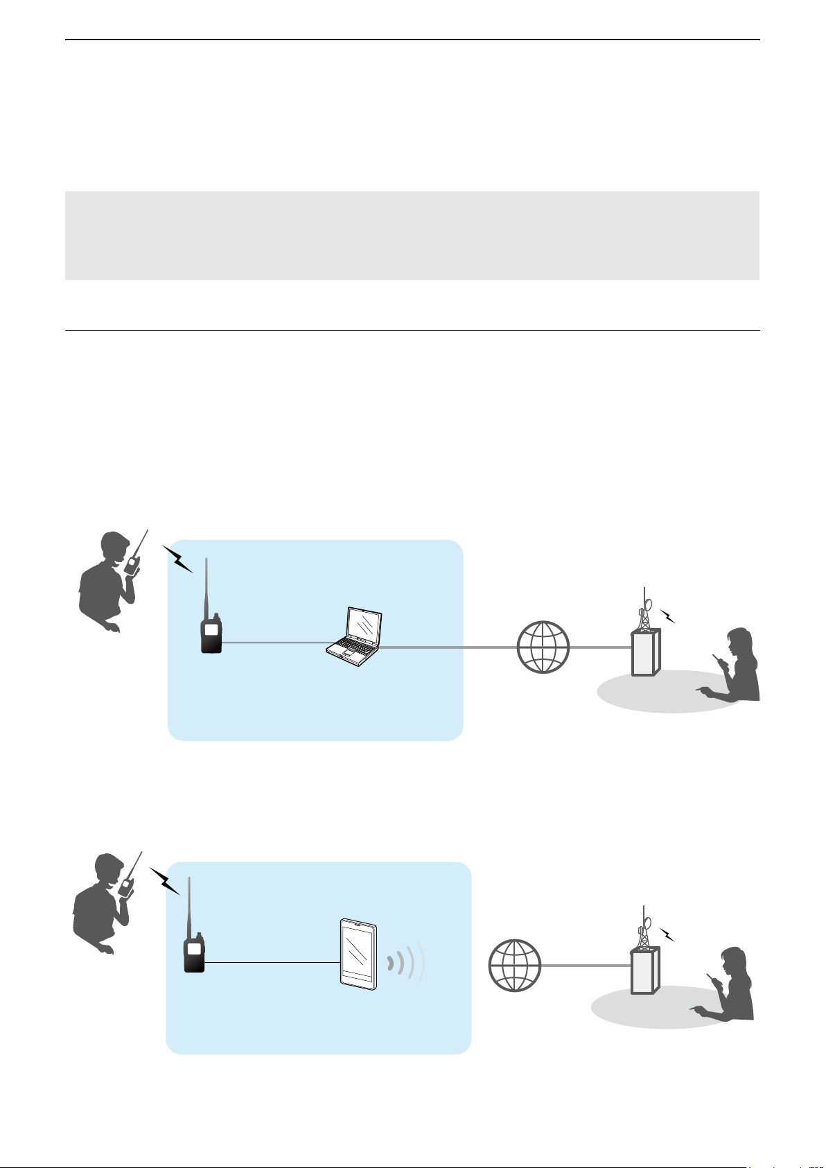
Terminal mode
The Terminal mode enables you to make Gateway calls through the Internet by using a Windows, Android, or iOS
device that is running the RS-MS3W, RS-MS3A, or RS-MS3I application.
In the Terminal mode, the transceiver does not transmit or receive RF signals through the antenna. The
communication is routed through only the Internet.
gateway control
Transceiver
Other station
Windows, Android,
or iOS device
D-STAR repeater
Access Point mode
1
The Access Point mode enables you to use another D-STAR transceiver and remotely*
make Gateway calls
through an Access point transceiver when connected to a Windows, Android, or iOS device that is running the
RS-MS3W, RS-MS3A, or RS-MS3I application.
Access point
Other station
Transceiver
Remote D-STAR
transceiver*
*1 Within the transmit and receive range of the Access point transceiver. The range will vary, depending on the operating
environment.
*2 Any model as long as the transceiver is D-STAR capable. Only one D-STAR transceiver can access the Access Point at the
same time.
2
Windows, Android,
or iOS device
D-STAR repeater
NOTE: When using the DV Gateway function
• When operating in the Access Point mode, you need two call signs. One for the Access Point transceiver and one for the
Remote D-STAR transceiver. (p. 6)
• You need an Internet connection with an IPv4 Global IP address. If you use a cellular system, you need an IPv4 Global IP
address assigned to your Windows, Android, or iOS device.
1
Page 2
■ About the transceivers
In this document, using the following transceivers is described.
System requirements
RS-MS3W
USB connection
• Requirement item
RS-MS3A
USB connection
• Requirement item
• Usable application
version
Bluetooth connection
• Usable application
version
RS-MS3I
Bluetooth connection
• Usable application
version
• Usable transceiver
firmware version
ID-52A PLUS
ID-52E PLUS
Supplied USB cable
Supplied USB cable
Version 1.31 or later
Version 1.40 or later
Version 1.0.0 or later
Main CPU(CPU M)
1.10 or later
1
*
1
*
ID-52A
ID-52E
USB cable*
(User supplied)
USB cable*
Version 1.31 or later
N/A N/A N/A
N/A N/A N/A
2
Supplied USB cable*
2
Supplied USB cable*
Version 1.31 or later
ID-50A
ID-50E
ID-51A (PLUS2)
ID-51E (PLUS2)
ID-31A PLUS
ID-31E PLUS
1
OPC-2350LU
data cable*
1
OPC-2350LU
data cable*
3
3
N/A: Not Applicable
*1 If you do not use a supplied USB cable, confirm your USB cable meets the following conditions:
- Usable for data transfer and not for charging only.
- Fits the transceiver’s USB port (Type-C) and your device’s USB port.
2
*
Purchase the proper USB cable according to your device’s USB port.
• For the Micro-B port: OPC-2417
• For the Type-C port: OPC-2418
• For the Type-A port: User supplied (Usable for data transfer and not for charging only)
3
*
If your Android device has a USB Type-C port, you need a USB On-The-Go (OTG) adapter to convert the data cable’s plug
to USB Type-C.
data cable (USB Micro-B/USB Micro-B)
data cable (USB Micro-B/USB Type-C)
NOTE: When you use a PC, download the USB driver and the installation guide from the Icom website.
• When using the OPC-2350LU, enter “OPC-2350LU” into the Search box in the site.
• When using other cable, enter the transceiver’s model name into the Search box in the site.
Icom website
https://www.icomjapan.com/support/
2
Page 3

■ System requirements (As of November 2024)
Software / Application System requirements
Operating system
Microsoft Windows 11 (64 bit)
When you use a PC
RS-MS3W
When you use an
Android device
RS-MS3A
When you use an iOS
device
RS-MS3I
Microsoft Windows 10 (32/64 bit)
L Except for Windows on ARM.
USB port
A USB 1.1 or USB 2.0
Data device for Android™
• Android™ version 8.0 or later
The RS-MS3A has been tested with Android 8.x, 9, 10, 11, 12, 13 and 14.
L If your device is Android version 5.x.x to 7.XX, you can use RS-MS3A version 1.32, but
cannot update RS-MS3A.
L If your device is Android version 4.x.x, you can use RS-MS3A version 1.20, but cannot
update RS-MS3A.
• USB host function on the Android™ device or Bluetooth function on the Android
device
L The USB host function is needed to use a USB device with an Android device. To check
whether or not your Android device has the USB host system, ask the Android device’s
manufacturer.
L Bluetooth connection is compatible with only the ID-52A PLUS/ID-52E PLUS.
Data device for iOS™
• iOS™ version 15 or later, iPadOS version 15 or later
The RS-MS3I has been tested with iOS 15, 16, 17, 18, and iPadOS 15, 16, 17, 18.
• Bluetooth function on the iOS™ device
L Bluetooth connection is compatible with only the ID-52A PLUS/ID-52E PLUS.
L Display indications may differ depending on the PC, Android, or iOS device’s OS.
L In addition to this document, read the RS-MS3W, RS-MS3A, or RS-MS3I instruction manual. They can be downloaded from
the Icom website.
Icom and the Icom logo are registered trademarks of Icom Incorporated (Japan) in Japan, the United States, the United
Kingdom, Germany, France, Spain, Russia, Australia, New Zealand, and/ or other countries.
The Bluetooth
Icom Inc. is under license. Other trademarks and trade names are those of their respective owners.
Microsoft and Windows are trademarks of the Microsoft group of companies.
Google, the Google Logo, Google Play, the Google Play logo, Android and the Android logo are registered trademarks or
trademarks of Google LLC.
IOS is a trademark or registered trademark of Cisco in the U.S. and other countries and is used under license.
iPadOS is a trademark of Apple Inc., registered in the U.S. and other countries and regions.
App Store is a service mark of Apple Inc.
All other products or brands are registered trademarks or trademarks of their respective holders.
®
word mark and logos are registered trademarks owned by Bluetooth SIG, Inc. and any use of such marks by
3
Page 4

1. Preparation
About the transceivers ..............................................................................2
System requirements ...............................................................................3
Entering your call sign in the RS-MS3W, RS-MS3A, or RS-MS3I ............5
D When operating in the Terminal mode: .............................................................5
D When operating in the Access Point mode: ......................................................6
Setting up a network .................................................................................7
D When connecting your device to the Internet using a router ............................9
D When connecting your device to the Internet using a cellular system ............10
D When connecting your device to the Internet using a mobile router ...............11
2. When using the RS-MS3W/RS-MS3A/RS-MS3I
Setting up the RS-MS3W .......................................................................12
D Installing the RS-MS3W ..................................................................................12
D Connecting the data cable ..............................................................................12
D COM port settings ...........................................................................................12
D Setting the RS-MS3W .....................................................................................12
Setting up the RS-MS3A ........................................................................13
D Installing the RS-MS3A ...................................................................................13
D When connecting with the data cable .............................................................13
D When connecting to the Bluetooth function .....................................................14
D Setting the RS-MS3A ......................................................................................14
Setting up the RS-MS3I ..........................................................................15
D Installing the RS-MS3I ....................................................................................15
D Connecting to the Bluetooth function ..............................................................15
D Setting the RS-MS3I .......................................................................................15
3. Terminal mode operation
Setting the Terminal mode ...................................................................... 16
D When using the ID-31A/E PLUS, ID-51A/E (PLUS2), ID-52A/E, ID-50A/E .....16
D When using the ID-52A/E PLUS .....................................................................17
Operating in the Terminal mode ............................................................. 18
D Setting “TO” (Destination) to make a call ........................................................19
4. Access Point mode operation
Setting the Access Point mode ...............................................................22
D When using the ID-31A/E PLUS, ID-51A/E (PLUS2), ID-52A/E, ID-50A/E .....22
D When using the ID-52A/E PLUS .....................................................................23
Operating in the Access Point mode ......................................................24
D About the Quick Tuning function ....................................................................25
Making a Gateway call through the Access point transceiver ................26
D When using the DR function ...........................................................................27
D When not using the DR function .....................................................................29
5. Troubleshooting
Error messages of the RS-MS3W, RS-MS3A, and RS-MS3I ................31
Troubleshooting for the Terminal mode operation .................................. 33
Troubleshooting for the Access Point mode operation ........................... 34
4
Page 5

Preparation
1
■ Entering your call sign in the RS-MS3W, RS-MS3A, or RS-MS3I
DWhen operating in the Terminal mode:
IMPORTANT:
• Register your own call sign (MY) at a gateway server.*
• Register the Terminal/AP call sign that is set in the RS-MS3A, RS-MS3I, or RS-MS3W to the RS-RP3C as the
access point.*
* Ask the gateway repeater administrator for details.
1. Open the RS-MS3W, RS-MS3A, or RS-MS3I on your Windows, Android, or iOS device.
2. Enter the connected transceiver’s My Call Sign in “Terminal/AP Call sign.”
L Information
• The Terminal Call sign should be 8 characters. Enter spaces between MY Call Sign and the 8th character.
• Enter a unique ID suffix between A and Z, except for G, I, and S, at the end of MY Call Sign for the 8th character.
• Call signs shown below are just examples.
When using a Windows device:
Transceiver
MY Call Sign:
JA3YUA
When using a mobile device:
Transceiver
MY Call Sign:
JA3YUA
Other station
Windows device
Enter “JA3YUA A” in
“Terminal/AP Call sign” in
the RS-MS3W.
Other station
Mobile device
Enter “JA3YUA A” in
“Terminal/AP Call sign”
in the RS-MS3A or
RS-MS3I.
NOTE for your own Call Sign on the Terminal mode (ID-52A PLUS/ID-52E PLUS only):
You can set your own call sign in terminal mode. ([MENU] > SET > My Station > My Call Sign (TM))
L As the default, “Same as Normal DV” is selected. ([MENU] > SET > My Station > My Call Sign)
L If you edit My Call Sign (TM), your own call sign will also be changed.
5
Page 6
Preparation
1
■ Entering your call sign in the RS-MS3W, RS-MS3A, or RS-MS3I
DWhen operating in the Access Point mode:
IMPORTANT:
• Register your call sign (MY) at a gateway server.*
• Register the Terminal/AP call sign that is set in the RS-MS3A, RS-MS3I or RS-MS3W to the RS-RP3C as the
access point.*
* Ask the gateway repeater administrator for details.
1. Open the RS-MS3W, RS-MS3A, or RS-MS3I on your Windows, Android, or iOS device.
2. Enter your Access Point (AP) transceiver’s My Call Sign in “Terminal/AP Call sign.”
L Information
• The AP Call sign should be 8 characters. Enter spaces between MY Call Sign and the 8th character.
• Enter a unique ID suffix between A and Z, except for G, I, and S, at the end of the Access Point transceiver’s
MY Call Sign for the 8th character.
• Call signs shown below are just examples.
When using a Windows device:
Remote D-STAR
transceiver*
MY Call Sign: JA3YUA
Access point
transceiver
MY Call Sign:
JL3YRP
When using a mobile device:
Remote D-STAR
transceiver*
MY Call Sign: JA3YUA
Access point
Other station
Windows device
Enter “JL3YRP D” in
“Terminal/AP Call sign”
in the RS-MS3W.
Access point
Access point
transceiver
MY Call Sign:
JL3YRP
* Any model as long as the transceiver is D-STAR capable.
Only one D-STAR transceiver can access the Access Point at the same time.
Mobile device
Enter “JL3YRP D” in
“Terminal/AP Call sign”
in the RS-MS3A or RS-MS3I.
6
Other station
Page 7

Preparation
1
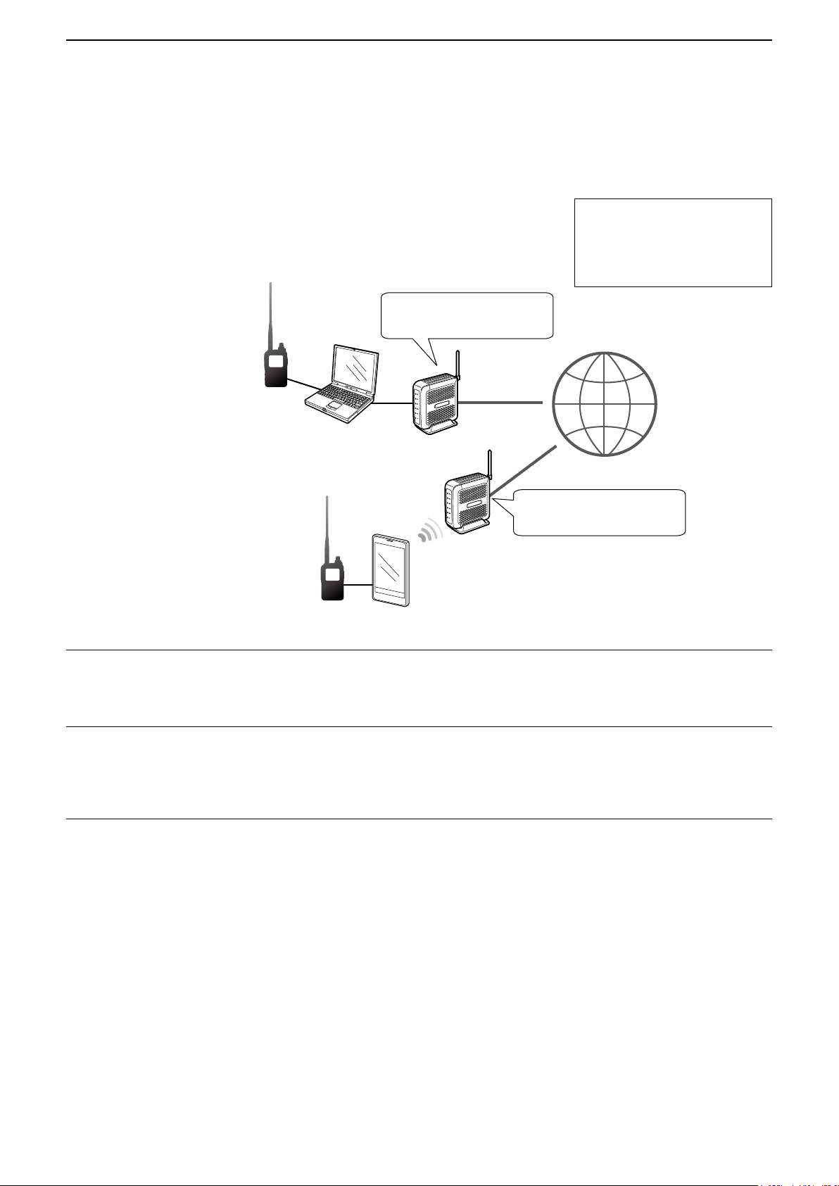
■ Setting up a network
Before using the DV Gateway function, you have to set up a network.
1. When connecting your device*
2. When connecting your device*1 to the Internet using a cellular system (p. 10)
3. When connecting your device*1 to the Internet using a mobile router (p. 11)
NOTE: Depending on your contract, you may be charged a large or additional communication fee. Ask your
Internet service provider about the content of your contract.
1
1
to the Internet using a router (p. 9)
1
*
Windows, Android, or iOS device
3
*2
2
2
*
You can use a cellular system compatible computer.
7
Page 8

Preparation
CallerCaller
1
■ Setting up a network
About the UDP Hole Punch function
When both the caller station and the called station use the Terminal or Access Point mode, the caller station
does not need to:
• Assign an IPv4 Global IP address to the router’s WAN port and forward port 40000 when connecting to the Internet using
the router.
• Use a device assigned a static or dynamic IPv4 Global IP address.
CQ CQ CQ,
CQ CQ CQ,
this is JA3YUA.
this is JA3YUA.
InternetInternet
CQ CQ CQ,
CQ CQ CQ,
this is JA3YUA.
this is JA3YUA.
Forward
port 40000.
JA3YUA,
JA3YUA,
this is JM1ZLK.
this is JM1ZLK.
CalledCalled
CallerCaller
JA3YUA,
JA3YUA,
this is JM1ZLK.
this is JM1ZLK.
No need to
forward port 40000.
L Information
• Depending on your Network environment, you may not be able to use this function.
• The caller station must set “UDP Hole Punch” to “ON” in the RS-MS3W/RS-MS3A/RS-MS3I to use this
function.
When not using this function, set “UDP Hole Punch” to “OFF.”
• A few minutes* after the call, the caller station cannot receive from the called station. In this case, the caller
station must transmit to the called station again.
* Less than 3 minutes, depending on the router.
NOTE:
• Use version of the RS-MS3W/RS-MS3A/RS-MS3I application software, as shown below.
RS-MS3W: version 1.30 or later
RS-MS3A: version 1.31 or later
RS-MS3I: version 1.0.0 or later
• The caller station cannot communicate with the called station when:
- The caller station is using an earlier version software or firmware.
- The called station using an earlier version software or firmware.
- The called station calls through a local repeater instead of using the Terminal or Access Point mode.
• Even if using the latest version, the called station needs to forward port 40000 when connecting to the
Internet using a router, or to use a device assigned a static or dynamic Global IP address to communicate
with the caller station.
CalledCalled
Not forwarding
port 40000
8
InternetInternet
Forwarding
port 40000
CQ CQ CQ,
CQ CQ CQ,
this is JM1ZLK.
this is JM1ZLK.
Page 9
Preparation
1
■ Setting up a network
DWhen connecting your device to the Internet using a router
The following are required to use the DV Gateway function.
• An Internet connection with an IPv4 Global IP address
• A static* local IP address set to your Windows, Android, or iOS device
• Port forwarding of port 40000
Needs a Global IP address.
When Global IP address is
not assigned or the port is not
forwarded, see the “About the
UDP Hole Punch function.”
(P.8)
* A static IP address to the
Windows, Android, or iOS
device is recommended.
1. A Global IP address
A static or dynamic IPv4 Global IP address assigned to the router is needed.
L Your router may not have a Global IP address, depending on your Internet service provider.
Ask your Internet service provider about the Global IP address setting.
2. Setting a static local IP address to your device
When using a router, you need to set a static local IP address to the Windows, Android, or iOS device.
L Usable IP addresses differ, depending on your router. Ask the router’s manufacturer for details.
L Do not set the same IP address to two or more devices that are connected to the same router.
L Ask your device’s manufacturer about the setting details.
3. Port forwarding
When using a router, enable communication with the Internet, as described below.
z Forward the port number 40000 that is used in the RS-MS3W, RS-MS3A, or RS-MS3I.
z “UDP” should be used as the port protocol.
z Set a static local IP address in Procedure 2 (2. Setting a static local IP address to your device) as a destination
port.
L Ask the router’s manufacturer about how to forward the port.
L Only one Windows, Android, or iOS device connected to the router can use the DV Gateway function at the same time.
L Depending on the router settings, you must configure the IP filter settings. Check the router’s manual on how to configure
the settings.
Forward port
number 40000.
Needs a Global IP address.
Forward port
number 40000.
→ When using a Windows device, go to “Setting up the RS-MS3W.” (p. 12)
→ When using an Android device, go to “Setting up the RS-MS3A.” (p. 13)
→ When using an iOS device, go to “Setting up the RS-MS3I.” (p. 15)
9
Page 10

Preparation
1
■ Setting up a network
DWhen connecting your device to the Internet using a cellular system
A Global IP address is required to use the DV Gateway function.
Needs a Global IP address.
When Global IP address is not
assigned, see the “About the UDP
Hole Punch function.” (P.8)
*
Needs a Global IP address.
You can use a cellular system compatible computer.
*
A Global IP address
A static or dynamic IPv4 Global IP address assigned to your Windows, Android, or iOS device is needed.
Ask your Internet service provider to provide a Global IP address to your device.
NOTE:
• Turn OFF your Wi-Fi setting when you operate using a cellular system.
• Communication errors may occur when using a cellular system.
• Depending on your contract, you may be charged a large or additional communication fee. Ask your cellular system
company about the content of your contract.
→ When using a Windows device, go to “Setting up the RS-MS3W.” (p. 12)
→ When using an Android device, go to “Setting up the RS-MS3A.” (p. 13)
→ When using an iOS device, go to “Setting up the RS-MS3I.” (p. 15)
10
Page 11

Preparation
1
■ Setting up a network
DWhen connecting your device to the Internet using a mobile router
The following items are required to use the DV Gateway function.
• An Internet connection with an IPv4 Global IP address
• A static* local IP address set to your Windows, Android, or iOS device
• Port forwarding of port 40000
Needs a Global IP address.
When Global IP address is
not assigned or the port is not
forwarded, see the “About the
UDP Hole Punch function.”
(P.8)
* A static IP address to the
Windows, Android, or iOS
device is recommended.
1. A Global IP address
A static or dynamic IPv4 Global IP address assigned to the router is needed.
L Your router may not have a Global IP address, depending on your Internet service provider.
Ask your Internet service provider about the Global IP address setting.
2. Setting a static local IP address to your device
When using a mobile router, you need to set a static local IP address to the Windows, Android, or iOS device.
L Usable IP address differs depending on your router. Ask the router’s manufacturer for details.
L Do not set the same IP address to two or more devices that are connected to the same router.
L Ask your device’s manufacturer about the setting details.
Forward port number
40000.
Needs a Global IP address.
Forward port number
40000.
3. Port forwarding
When using a mobile router, enable communication with the Internet, as described below.
z Forward the port number 40000 to your cellular device.
z “UDP” should be used as the port protocol.
z Set a static local IP address in Procedure 2 (2. Setting a static local IP address to your device) as a destination
port.
L Ask the mobile router’s manufacturer about how to forward the port.
L Only one Windows, Android, or iOS device connected to the mobile router can use the DV Gateway function at the same
time.
L Depending on the router settings, you must configure the IP filter settings. Check the router’s manual on how to configure
the settings.
→ When using a Windows device, go to “Setting up the RS-MS3W.” (p. 12)
→ When using an Android device, go to “Setting up the RS-MS3A.” (p. 13)
→ When using an iOS device, go to “Setting up the RS-MS3I.” (p. 15)
11
Page 12

Setting up the RS-MS3W/RS-MS3A/RS-MS3I
2
■ Setting up the RS-MS3W
The RS-MS3W is a Windows
You can download it from the Icom website.
L See page 3 for system requirements.
application to use the DV Gateway function.
DInstalling the RS-MS3W
Download the latest RS-MS3W and its instruction
manual from the Icom website.
Read the RS-MS3W instruction manual on how to
install the software.
L Search by “RS-MS3W.”
https://www.icomjapan.com/support/
DConnecting the data cable
Connect the transceiver to the Windows using the
data cable. (Example: ID-52A/E)
Windows
Data cable
To the
[USB] port
When using the ID-52A/ID-52E/ID-50A/ID-50E/
ID-52A PLUS/ID-52E PLUS
Confirm the “USB Connect” in the Set mode is set to
“Serialport.”
([MENU] > SET > Function > USB Connect)
L For the ID-52A/ID-52E or ID-52A PLUS/ID-52E PLUS,
“
” is displayed when connecting to a PC in the
Serialport mode.
To a USB port
DSetting the RS-MS3W
Set the RS-MS3W to start using the DV Gateway
function.
L The screen may be different, depending on the
application version.
Read the RS-MS3W instruction manual about each
setting item.
NOTE: About the Firewall setting
When you use a firewall security software, a
communication error may occur by the firewall
blocking the necessary ports or data.
Before using the DV Gateway function, confirm that
the RS-MS3W’s communication is not blocked.
L Ask your firewall security software’s manufacturer
about the setting details.
When using the ID-31A PLUS/ID-31E PLUS/
ID-51A (PLUS2)/ID-51E (PLUS2)
Connect the data cable to the [DATA] jack.
NOTE: Turn OFF the transceiver before connecting
or disconnecting the data cable.
DCOM port settings
Set the data port.
1. After connecting, turn ON the transceiver.
2. Click “Com Port (P)” in the “Settings (S).”
• Com Port Setting window is displayed.
3. Select the COM port number that the data cable
is connected to.
L Click “▼” to display the COM ports on a drop-down
list.
L See the data cable’s Installation Guide you can
download on the Icom website, for details on
checking the COM port number.
4. Click <OK>.
12
Page 13

Setting up the RS-MS3W/RS-MS3A/RS-MS3I
2
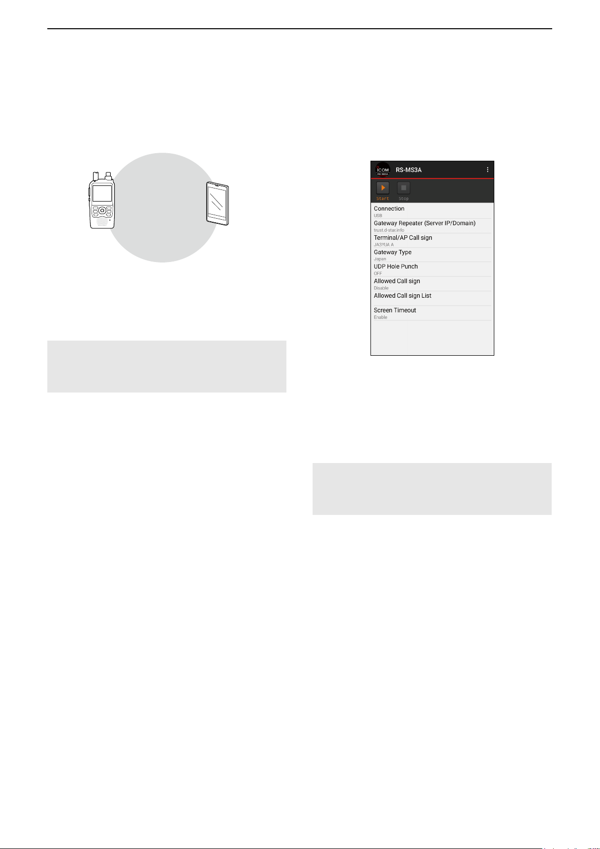
■ Setting up the RS-MS3A
The RS-MS3A is an application for Android device to use the DV Gateway function.
Download the application from Google Play.
L See page 3 for system requirements.
ID-52A PLUS/ID-52E PLUS can connect the transceiver to an Android device using the Bluetooth.
D
DInstalling the RS-MS3A
1. Start the Android device.
2. Touch “Play store.”
3. Enter “RS-MS3A.”
L Do not abbreviate the application name to certainly
find it.
4. Touch “ (search)”
5. Touch “RS-MS3A.”
• The RS-MS3A application information is displayed.
L If your Android device is not compatible with the RS-
MS3A, the application is not displayed.
6. Touch “Install.”
7. Touch “Agree to download.”
• Starts installing the application.
• After the installation is completed, the icon is
displayed on your home screen.
When connecting with the data cable
Connect the transceiver to the Android device using
the data cable. (Example: ID-52A/E)
Android device with
the USB host function
Data cable
To the
[USB] port
ID-52A/ID-52E:
• Connect the USB Micro-B connector (in the case
of OPC-2417, the one with the white tube) to the
transceiver and the other to an Android device.
• If “ ” is not displayed when connecting the
transceiver to an Android device, set “USB
Connect” to “Serialport.”
([MENU] > SET > Function > USB Connect)
To a USB port
ID-50A/ID-50E or ID-52A PLUS/ID-52E PLUS:
Confirm the “USB Connect” in the Set mode is set to
“Serialport.”
([MENU] > SET > Function > USB Connect)
• When connecting the transceiver to an Android
device, “ ” is displayed on the ID-52A PLUS/
ID-52E PLUS.
ID-31A PLUS/ID-31E PLUS/
ID-51A (PLUS2)/ID-51E (PLUS2):
Connect the data cable to the [DATA] jack.
NOTE:
• Turn OFF the transceiver before connecting or
removing the data cable.
• Remove the data cable when you do not use it.
Otherwise, the battery will be quickly exhausted.
If you want to reduce the battery consumption of your
Android device while the data cable is connected, set
the following item on the transceiver to “OFF.”
( [MENU] > SET > Function >
USB Power Input (Phone, Tablet, PC))
• If the application selection window is displayed, select
“RS-MS3A” to start the application.
13
Page 14
Setting up the RS-MS3W/RS-MS3A/RS-MS3I
2
■ Setting up the RS-MS3A
D When connecting to the Bluetooth
function
Bluetooth
Android device
ID-52A PLUS/ID-52E PLUS:
Before connecting to an Android device, you must
pair with it. See the transceiver’s Advanced manual
for connection details.
NOTE: Disconnect a paired the Android device
when you are not using the RS-MS3A.
When you leave it connected, the Android device’s
battery is quickly exhausted.
D Setting the RS-MS3A
Set the RS-MS3A to start using the DV Gateway
function.
L The screen may be different, depending on the
application version.
Read the RS-MS3A instruction manual about each
setting item.
L Search by “RS-MS3A.”
https://www.icomjapan.com/support/
NOTE for connecting with a USB cable:
When an Android device does not work properly,
try moving the Access Point transceiver to a distant
place from the Android device.
14
Page 15

Setting up the RS-MS3W/RS-MS3A/RS-MS3I
2
■ Setting up the RS-MS3I
The RS-MS3I is an application for iOS device to use the DV Gateway function.
Download the application from App Store.
L See page 3 for system requirements.
ID-52A PLUS/ID-52E PLUS can connect the transceiver to an iOS device using the Bluetooth.
DInstalling the RS-MS3I
1. Start the iOS device.
2. Touch “App Store.”
3. Touch “ (search)”
4. Enter “RS-MS3I.” in the search field.
• The RS-MS3I will be displayed as the search result.
L You may need to enter “RS-MS3I” as a complete
word to get the search result.
L If your iOS device is not compatible with the
RS-MS3I, the application is not displayed.
5. Touch “RS-MS3I.”
6. Touch <GET>.”
• Starts installing the application.
• After the installation is completed, the icon is
displayed on your home screen.
DConnecting to the Bluetooth
function
Bluetooth
DSetting the RS-MS3I
Set the RS-MS3I to start using the DV Gateway
function.
L The screen may be different, depending on the
application version.
iOS device
ID-52A PLUS/ID-52E PLUS:
Before connecting to an iOS device, you must pair
with it. See the transceiver’s Advanced manual for
connection details.
NOTE:
• You cannot pair with an iOS device in its Settings
app. To pair with an iOS device, use Icom
application.
• Disconnect a paired the iOS device when you
are not using the RS-MS3I. When you leave it
connected, the iOS device’s battery is quickly
exhausted.
Read the RS-MS3I instruction manual about each
setting item.
L Search by “RS-MS3I.”
https://www.icomjapan.com/support/
15
Page 16

Terminal mode operation
3
■ Setting the Terminal mode
DWhen using the ID-31A/E PLUS, ID-51A/E (PLUS2), ID-52A/E, ID-50A/E
L In this document, the ID-52A/ID-52E is used as an example.
[Transceiver operation]
1. Push [MENU].
2. Select “DV Gateway.”
3. Select “<<Terminal Mode>>.”
When using the UDP Hole Punch function
Set “UDP Hole Punch” to “ON” in the RS-MS3W or
RS-MS3A. (p. 8)
“TM” is displayed
when using the
ID-31A PLUS/
ID-31E PLUS.
[Windows or Android operation]
L When using the RS-MS3A application, select “USB” in
the RS-MS3A “Connection.”
z Click (touch) <Start> in the RS-MS3W or
RS-MS3A.
L If an error message is displayed, see page 17 to
read the tips to solve the problem.
TIP: Canceling the Terminal mode
[Windows or Android operation]
1. Click (touch) <Stop>
[Transceiver operation]
2. Select “<<Normal Mode>>” in the Quick Menu or “DV Gateway” on the MENU screen.
L To display the Quick Menu, push [QUICK].
NOTE: In the Terminal mode
• The Power Save function and the Time Out Timer function are not activated.
• The Following items are automatically set.
ID-31A PLUS/ID-31E PLUS ID-51A (PLUS2)/ID-51E (PLUS2)/ID-52A/ID-52E/ID-50A/ID-50E
Receive mode: DV mode Receive mode: DV mode
DR function: ON* DR function: ON (MAIN band)*
FROM: MY Call Sign FROM: MY Call Sign
Dualwatch function: OFF*
* These settings do not return to the previous settings even if you cancel the Terminal mode.
• The Terminal mode is not automatically canceled even if you turn OFF the transceiver, then ON it again.
in the RS-MS3W or RS-MS3A.
TouchClick
16
Page 17

Terminal mode operation
3
■ Setting the Terminal mode
DWhen using the ID-52A/E PLUS
[Transceiver operation]
1. Push [MENU].
2. Select “DV Gateway.”
3. Select “DV Gateway Connection.”
4. Select “USB” or “Bluetooth.”
5. Select “<<Terminal Mode>>.”
When using the UDP Hole Punch function
Set “UDP Hole Punch” to “ON” in the RS-MS3W,
RS-MS3A, or RS-MS3I. (p. 8)
[Windows, Android, or iOS operation]
L When using the RS-MS3A application, select “Bluetooth
Connection Device” or “USB” in the RS-MS3A “Connection.”
z Click (touch) <Start> in the RS-MS3W,
RS-MS3A, or RS-MS3I.
L If an error message is displayed, see page 31 to
read the tips to solve the problem.
RS-MS3W RS-MS3A RS-MS3I
Click
• For Bluetooth connection, the Bluetooth icon is
displayed on the Standby screen of the transceiver.
Touch
Touch
L ID-52A PLUS/ID-52E PLUS can change the MAIN
band or SUB band in the terminal mode.
TIP: Canceling the Terminal mode
[Windows, Android, or iOS operation]
1. Click (touch) <Stop>
RS-MS3A, or RS-MS3I.
[Transceiver operation]
2. Push [VFO/MHz].
L You can also cancel by selecting “<<Normal
Mode>>” in the Quick Menu or “DV Gateway” on
the MENU screen. To display the Quick Menu, push
[QUICK].
NOTE: In the Terminal mode
• The Power Save function and the Time Out Timer
function are not activated.
• The Following items are automatically set.
Receive mode: DV mode
DR function: ON (MAIN band)*
FROM: MY Call Sign
* These settings do not return to the previous settings
even if you cancel the Terminal mode.
• The Terminal mode is not automatically canceled even
if you turn OFF the transceiver, then ON it again.
17
in the RS-MS3W,
Page 18

Terminal mode operation
3
■ Operating in the Terminal mode
You can operate the transceiver as described below in the Terminal mode.
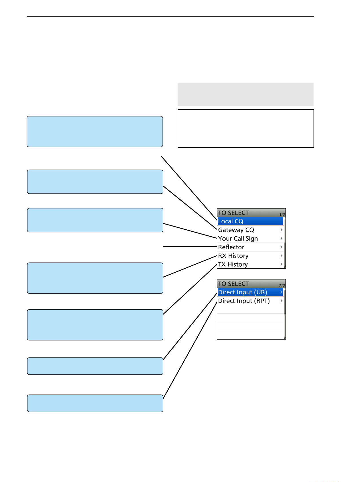
What you can do while in the Terminal mode
Display the TO SELECT screen.
Switch transmit or receive.
Display the RX HISTORY screen.
Open the MENU screen.
Turn the Key Lock function ON or OFF.
Open the Quick Menu*.
Audibly announce the displayed Call Sign.
Enter the Operating Call Sign Select mode.
Display the RX History list.
Adjust the audio volume level.
Set “TO” (Destination).
Turn the transceiver ON or OFF.
Push [ENT].
Hold down [PTT] or release it to transmit or receive.
L While transmitting, the TX/RX indicator lights orange.
L While receiving, the TX/RX indicator lights green.
L While receiving a signal through the Internet, you cannot
transmit.
Hold down [CD] for 1 second.
Push [MENU].
Hold down [LOCK] for 1 second.
Push [QUICK].
Hold down [SPCH] for 1 second.
L Hold down [QUICK] for 1 second when using the ID-31A
PLUS/ID-31E PLUS.
Check in the “Call Sign” setting.
([MENU] > SET > Call Sign)
L When using the ID-51A (PLUS2)/ID-51E (PLUS2)/ID-31A
PLUS/ID-31E PLUS, hold down [CS] for 1 second.
Hold down [RX→CS] for 1 second.
Rotate [VOL].
Rotate [DIAL].
Hold down [
L The Terminal mode is not automatically canceled even if
you turn OFF the transceiver, then ON it again.
] for 1 second.
* You can select the following items (Quick Menu) in
the Terminal mode.
<<Normal Mode>>
Group Select
Repeater Detail
DTMF TX
Voice TX
GPS Information
GPS Position
Display Type
D.SQL
( “DSQL” for the ID-51A (PLUS2)/ID-51E (PLUS2)/
ID-31A PLUS/ID-31E PLUS)
Voltage
<<REC Start>>
<<FM Radio ON>>
(For only the ID-52A PLUS/ID-52E PLUS)
<<FM Radio Mode>>
(For only the ID-52A PLUS/ID-52E PLUS)
<<GPS Logger Only>>
TIP: See the transceiver’s manual about each key
operation.
ID-31A PLUS/ID-31E PLUS
Basic manual Section 2, 3, 11
Advanced manual Section 4, 11
ID-51A (PLUS2)/ID-51E (PLUS2)
Basic manual Section 2, 4, 6
Advanced manual Section 8, 9, 16
ID-52A/ID-52E/ID-50A/ID-50E/
ID-52A PLUS/ID-52E PLUS
Basic manual Section 2, 3, D-STAR OPERATION
Advanced manual Section 5, 12
18
Page 19
Terminal mode operation
3
■ Operating in the Terminal mode
DSetting “TO” (Destination) to make a call
“CQCQCQ,” the destination repeater, or station call
sign must be set in “TO” when you make a DV mode
call.
You have 7 ways to set the destination.
By rotating [DIAL]
Rotate [DIAL] to select the repeater or Your Call
Sign displayed on the DR screen. (This operation is
disabled when “CQCQCQ” is set.)
L You can select the “Local CQ,” but cannot make a call.
To make a Gateway CQ call
“Gateway CQ” setting (p. 20)
Select a repeater from the Repeater List, if you want
to make a Gateway call.
To make a call to a specific station
“Your Call Sign” setting (p. 21)
Select the station call sign in the Your Call Sign list.
L You cannot make a call through a reflector.
NOTE: In the Terminal mode, you can make a
Gateway CQ call or a call to a specific station using
call sign routing.
TIP: How to change the repeater group:
When “Gateway CQ” is selected, you can change
the repeater group.
To change the repeater group on the DR screen,
push [QUICK], then select “Group Select.”
TO SELECT screen
To select from RX History
Setting from the RX History*
When you receive a call, repeater or caller station
data is saved in RX History.
Select the destination from the record.
To select from TX History
Setting from the TX History*
When you make a call, the destination repeater or
called station data is saved in TX History.
Select the destination from the record.
To directly enter the destination station call sign
Direct Input (UR)*
Directly enter the destination station’s call sign.
To directly enter the destination repeater call sign
Direct Input (RPT)*
Directly enter the destination repeater’s call sign.
* See the transceiver’s Advanced manual for details.
ID-31A PLUS/ID-31E PLUS: Section 4
ID-51A (PLUS2)/ID-51E (PLUS2): Section 8
ID-52A/ID-52E/ID-50A/ID-50E/
ID-52A PLUS/ID-52E PLUS: Section 5
19
Page 20

Terminal mode operation
3
■ Operating in the Terminal mode
D Setting “TO” (Destination) to make a call
Example: Making a Gateway CQ call
1. P
ush [ENT].
• Displays the TO SELECT screen.
2. Select “Gateway CQ.”
3. Select the repeater group where your destination
repeater is listed.
(Example: “13: Japan”)
4. Select the destination repeater.
(Example: “Hirano/Icom”)
5. Hold down [PTT] to transmit.
• While transmitting, the TX/RX indicator lights orange.
L While receiving a signal through the Internet, you
cannot transmit.
6. Release [PTT] to receive.
L If you cannot receive a reply, see page 33 to read
the tips to solve the problem.
20
Page 21
Terminal mode operation
3
■ Operating in the Terminal mode
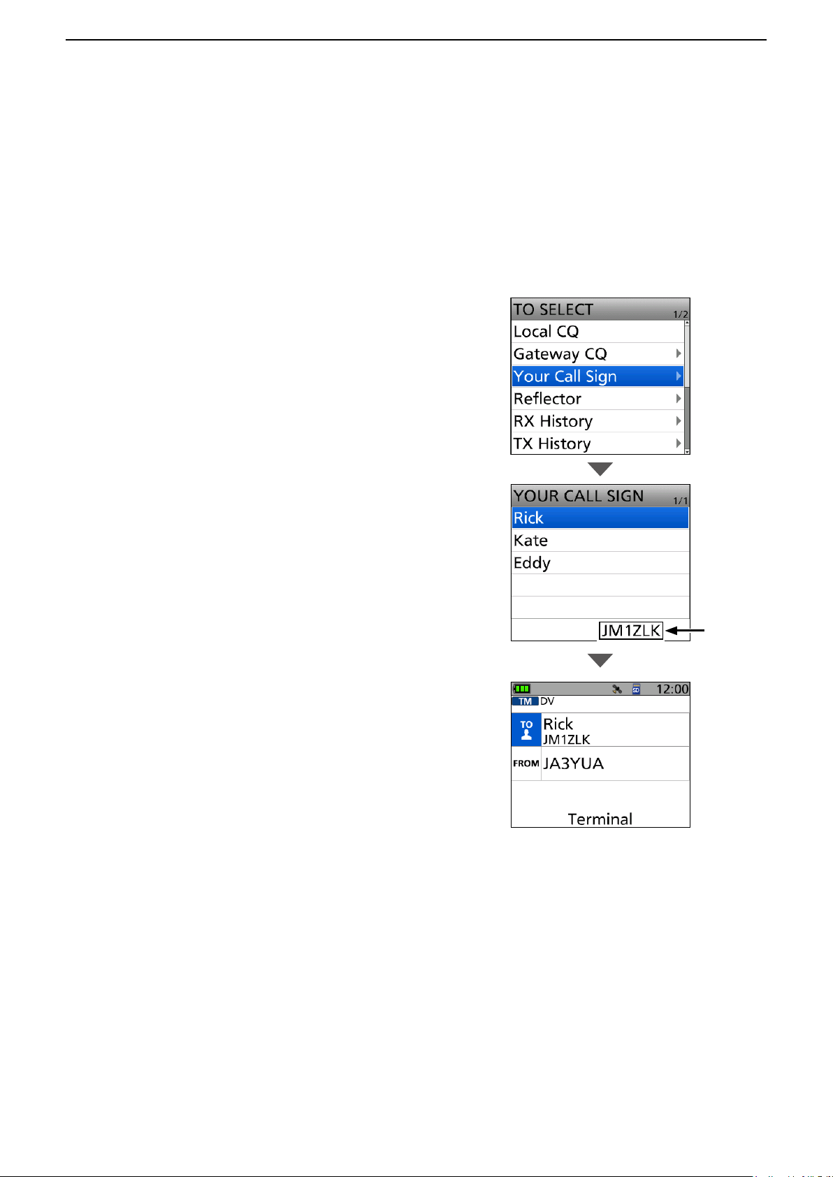
D Setting “TO” (Destination) to make a call
Example: Making a call to a specific station
1. Push [ENT].
• Displays the TO SELECT screen.
2. Select “Your Call Sign.”
3. Select the destination. (Example: “Rick”)
• “Rick” is displayed in “TO.”
4. Hold down [PTT] to transmit.
• While transmitting, the TX/RX indicator lights orange.
L While receiving a signal through the Internet, you
cannot transmit.
5. Release [PTT] to receive.
L If you cannot receive a reply, see page 33 to read
the tips to solve the problem.
The call sign
of the selected
station is
displayed.
21
Page 22

Access Point mode operation
4
■ Setting the Access Point mode
DWhen using the ID-31A/E PLUS, ID-51A/E (PLUS2), ID-52A/E, ID-50A/E
In this section, set an Access Point transceiver.
L In this document, the ID-52A/ID-52E is used as an example.
[Access Point transceiver operation]
1. Push [MENU].
2. Select “DV Gateway.”
3. Select “<<Access Point Mode>>.”
4. Rotate [DIAL] to set the operating frequency.
L The frequency is used to communicate with the
Remote D-STAR transceiver.
L In the Access Point mode, you can change the
operating frequency.
NOTE: BE SURE to check your local regulations
or laws to select the appropriate operating
frequency.
[Windows or Android operation]
L When using the RS-MS3A application, select “USB” in
the RS-MS3A “Connection.”
z Click (touch) <Start> in the RS-MS3W or
RS-MS3A.
L If an error message is displayed, see page 31 to
read the tips to solve the problem.
When using the UDP Hole Punch function
Set “UDP Hole Punch” to “ON” in the RS-MS3W or
RS-MS3A. (p. 8)
Set the
operating
frequency
“AP” is displayed
when using the
ID-31A PLUS/
ID-31E PLUS.
Click
Touch
TIP: Canceling the Access Point mode
[Windows or Android operation]
1. Click (touch) <Stop>
[Access Point transceiver operation]
2. Select “<<Normal Mode>>” in the Quick Menu or “DV Gateway” on the MENU screen.
L To display the Quick Menu, push [QUICK].
NOTE: In the Access Point mode
• The Power Save function is not activated.
• Following items are automatically set.
Operating mode:
Frequency band:
Receive mode:
Dualwatch function:
Duplex mode:
* These settings do not return to the previous settings even if you cancel the Access Point mode.
• The Access Point mode is not automatically canceled even if you turn OFF the transceiver, then ON it again.
VFO mode*
VHF* (Only when using the ID-51A (PLUS2)/ID-51E (PLUS2) and the AIR band is set.)
DV mode*
OFF* (Only when using the ID-51A (PLUS2)/ID-51E (PLUS2)/ID-52A/ID-52E/ID-50A/ID-50E.)
OFF*
in the RS-MS3W or RS-MS3A.
VHF* or UHF* (Only when using the ID-52A/ID-52E/ID-50A/ID-50E, when a frequency that is in the
AIR band is selected, when a frequency that is out of the amateur radio band is selected, or when a
frequency that cannot be set in the DV mode is selected.)
22
Page 23
Access Point mode operation
4
■ Setting the Access Point mode
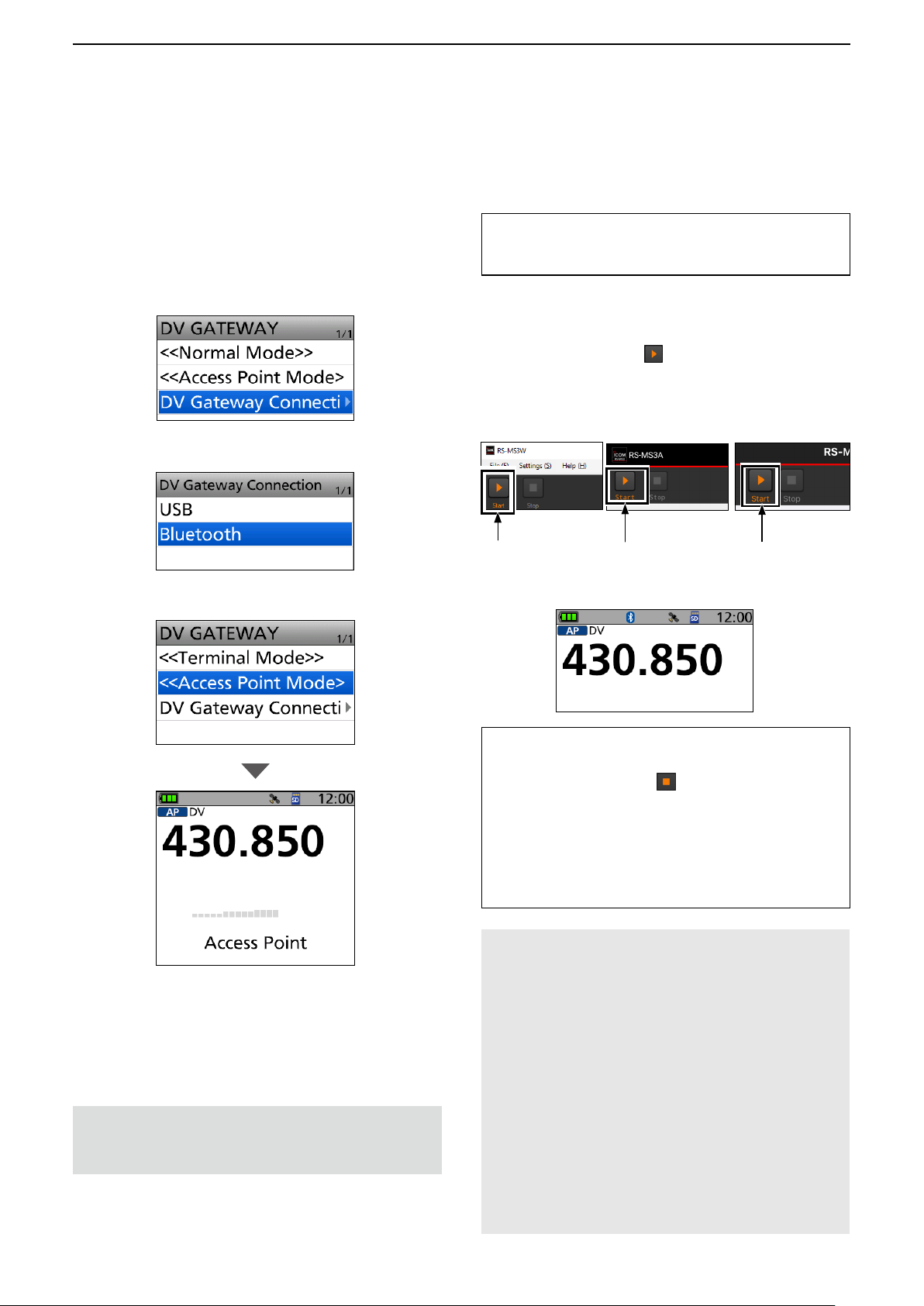
DWhen using the ID-52A/E PLUS
[Access Point transceiver operation]
1. Push [MENU].
2. Select “DV Gateway.”
3. Select “DV Gateway Connection.”
4. Select “USB” or “Bluetooth.”
5. Select “<<Access Point mode>>.”
When using the UDP Hole Punch function
Set “UDP Hole Punch” to “ON” in the RS-MS3W,
RS-MS3A, or RS-MS3I. (p. 8)
[Windows, Android, or iOS operation]
L When using the RS-MS3A application, select “Bluetooth
Connection Device” or “USB” in the RS-MS3A “Connection.”
z Click (touch) <Start> in the RS-MS3W,
RS-MS3A, or RS-MS3I.
L If an error message is displayed, see page 31 to
read the tips to solve the problem.
RS-MS3W RS-MS3A RS-MS3I
Click
• For Bluetooth connection, the Bluetooth icon is
displayed on the Standby screen of the transceiver.
Touch
Touch
6. Rotate [DIAL] to set the operating frequency.
L The frequency is used to communicate with the
Remote D-STAR transceiver.
L In the Access Point mode, you can change the
operating frequency.
NOTE: BE SURE to check your local regulations
or laws to select the appropriate operating
frequency.
TIP: Canceling the Access Point mode
[Windows, Android, or iOS operation]
1. Click (touch) <Stop>
in the RS-MS3W,
RS-MS3A, or RS-MS3I.
[Access Point transceiver operation]
2. Select “<<Normal Mode>>” in the Quick Menu
or “DV Gateway” on the MENU screen.
L To display the Quick Menu, push [QUICK].
NOTE: In the Access Point mode
• The Power Save function is not activated.
• Following items are automatically set.
Operating mode:
Frequency band:
Receive mode: DV mode*
Dualwatch function:
Duplex mode:
* These settings do not return to the previous settings
even if you cancel the Access Point mode.
• The Access Point mode is not automatically canceled
even if you turn OFF the transceiver, then ON it again.
23
VFO mode*
VHF* or UHF* (Only when a
frequency that is in the AIR band is
selected, when a frequency that is out
of the amateur radio band is selected,
or when a frequency that cannot be
set in the DV mode is selected)
OFF*
OFF*
Page 24

Access Point mode operation
4
■ Operating in the Access Point mode
You can operate the Access Point transceiver as described below in the Access Point mode.
What you can do while in the Terminal mode
Display the RX HISTORY screen. Hold down [CD] for 1 second.
Push [SQL].
Turn the Monitor function ON or OFF
Open the MENU screen. Push [MENU].
Turn the Key Lock function ON or OFF. Hold down [LOCK] for 1 second.
Open the Quick Menu*. Push [QUICK].
Audibly announce the displayed Call Sign.
Select 1 MHz or 10 MHz tuning steps.
Select the transmit output power.
Adjust the audio volume level. Rotate [VOL].
Select an operating frequency. Rotate [DIAL].
Turn the transceiver ON or OFF.
L Rotate [DIAL] while pushing [SQL] to adjust the squelch level.
A weaker signal than the set squelch level is not transmitted
through the Internet.
Hold down [SPCH] for 1 second.
L Hold down [QUICK] for 1 second when using the
ID-31A PLUS/ID-31E PLUS.
Push [VFO/MHz].
L Push [V/MHz] when using the ID-31A PLUS/ID-31E PLUS/
ID-51A (PLUS2)/ID-51E (PLUS2)/ID-50A/ID-50E.
L You cannot select 10 MHz tuning steps in the
ID-31A PLUS/ID-31E PLUS/ID-52A/ID-52E/ID-50A/ID-50E/
ID-52A PLUS/ID-52E PLUS.
Hold down [LOW] for 1 second to select the transmit
output power between S-Low, Low1, Low2, Mid, and High.
L Hold down [LO] for 1 second to open the Select Output Power
window when using the ID-52A/ID-52E/ID-50A/ID-50E/
ID-52A PLUS/ID-52E PLUS.
L No icon appears when high power is selected.
L “SLO,” “LO1,” “LO2,” or “MID” appears when S-low, Low 1,
Low 2, or Mid power is selected.
Hold down [
L The Access Point mode is not automatically canceled even if
you turn OFF the transceiver, then ON it again.
] for 1 second.
* You can select the following items (Quick Menu) in
the Access Point mode.
<<Normal Mode>>
Band Select*
1
TS
1,2,3
ATT*
GPS Information
GPS Position
Home CH Set
Voltage
<<REC Start>>
<<GPS Logger Only>>
1
*
“Band Select” and “ATT” are not displayed when using
the ID-31A PLUS/ID-31E PLUS.
2
*
“ATT” is not displayed when using the
ID-51A (PLUS2)/ID-51E (PLUS2).
3
*
Not displayed when using the Access Point mode on
the B band.
TIP: See the transceiver’s manual about each key
operation.
ID-31A PLUS/ID-31E PLUS
Basic manual Section 2, 3, 11
Advanced manual Section 11
ID-51A (PLUS2)/ID-51E (PLUS2)
Basic manual Section 2, 4, 6
Advanced manual Section 9
ID-52A/ID-52E/ID-50A/ID-50E/
ID-52A PLUS/ID-52E PLUS
Basic manual Section 2, 3, D-STAR OPERATION
Advanced manual Section 5
24
Page 25

Access Point mode operation
4
■ Operating in the Access Point mode
DAbout the Quick Tuning function
1. In the VFO mode, push [VFO/MHz].
• Enters the 1 MHz Tuning Select mode, and the 1 MHz digit blinks.
L Push [V/MHz] when using the ID-31A PLUS/ID-31E PLUS/ID-51A (PLUS2)/ID-51E (PLUS2)/ID-50A/ID-50E.
L You can select the 10 MHz step by pushing [V/MHz] again only when using the ID-51A (PLUS2)/ID-51E (PLUS2).
blinks
2. Rotate [DIAL].
• The blinking digit is changed.
3. Push [VFO/MHz].
• Exits the 1 MHz Tuning Select mode.
L When using ID-51A (PLUS2)/ID-51E (PLUS2) and the 10 MHz step is selected, push [V/MHz] to cancel the Quick
Tuning function.
NOTE:
• To prevent interfering, hold down [SQL] to listen on the channel before transmitting.
• BE SURE to check your local regulations or laws to select the appropriate operating frequency.
25
Page 26

Access Point mode operation
4
■ Making a Gateway call through the Access point transceiver
In this section, set a Remote D-STAR transceiver you are going to operate.
L Read the Remote D-STAR transceiver’s instruction manual for setting details.
NOTE: While in the Access Point mode, you can make a Gateway CQ call or a call to an individual station
using call sign routing.
L You can select the “Local CQ,” but cannot make a call.
Example: When setting the operating frequency to 430.850 MHz,
and making a Gateway CQ call.
Remote D-STAR
transceiver*
Access Point
Other station
Access Point
transceiver:
Operating frequency:
430.850 MHz
UR: /JP1YIUA
MY: JA3YUA
* Any model as long as the transceiver is D-STAR capable.
Only one D-STAR transceiver can use the Access Point at the same time.
Operating frequency:
430.850 MHz
MY Call Sign:
JL3YRP
Enter “JL3YRP D”
to the RS-MS3W/
RS-MS3A/
RS-MS3I.
Hamacho 430
(JP1YIU A)
26
Page 27
Access Point mode operation
4
■ Making a Gateway call through the Access point transceiver
DWhen using the DR function
NOTE: If you have imported the Repeater List, you have to register the Access Point information again
because the Repeater List is overwritten.
In this document, the ID-51A (PLUS2)/ID-51E (PLUS2) is used as a Remote D-STAR transceiver as an example.
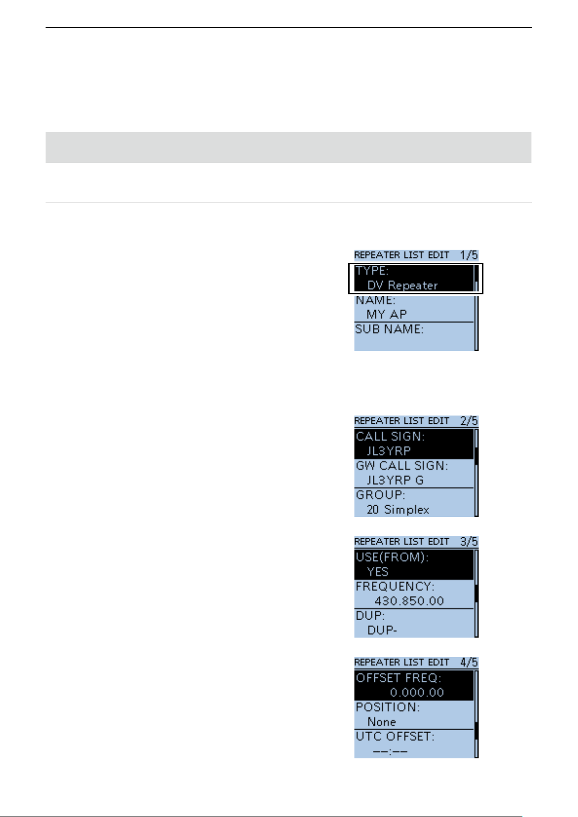
1. Register the Access Point information to the Repeater List
L Register the Access Point information in the MENU
screen.
(MENU > DV Memory > Repeater List)
1. Select a group you want to add your Access Point
information.
2. After selecting a group, open the Repeater List
Edit screen.
3. Set “DV Repeater” to “TYPE.” *
L “ DV Repeater” is used for Repeater operation in the
DV mode.
4. Enter your favorite name into “NAME” and “SUB
NAME.” (Example: MY AP)
5. Set the Access Point transceiver’s call sign to
“CALL SIGN.”
(Example: JL3YRP)
L After setting “CALL SIGN,” “GW CALL SIGN” is
automatically set.
6. Set “YES” to “USE (FROM).”
7. Set the Access Point transceiver’s operating
frequency to “FREQUENCY.”
(Example: 430.850)
8. Set “DUP” to “DUP–.”
(QUICK MENU > Add)
*
* For only the ID-31A/E PLUS, ID-51A/E (PLUS),
or ID-51A/E (PLUS2)
9. Set “0.000.00” to “OFFSET FREQ.”
10. Select “<<Add Write>>” and write the Access
Point information.
27
Page 28

Access Point mode operation
4
■ Making a Gateway call through the Access point transceiver
D When using the DR function (Continued)
2. Set the Access Point using the DR function
Set the Access Point registered in Procedure 1
( 1. Register the Access Point information to the
Repeater List) to “FROM.”
3. Set “TO” and transmit
1. Set “TO” destination.
(Example: Hamacho 430)
L You can select the “Local CQ,” but cannot make a
call.
2. Hold down [PTT] to transmit.
3. Release [PTT] to receive.
L If you cannot receive a reply, see page 35 to read
the tips to solve the problem.
28
Page 29

Access Point mode operation
4
■ Making a Gateway call through the Access point transceiver
DWhen not using the DR function
In this document, the ID-51A (PLUS2)/ID-51E (PLUS2) is
used as a Remote D-STAR transceiver as an example.
1. Enter the VFO mode.
Push [V/MHz].
2. Set the operating frequency.
Rotate [DIAL] to set the frequency that is set to the
Access Point transceiver. (Example: 430.850)
3. Set the Receive mode to “DV mode.”
Push [MODE] several times until “DV” is displayed.
L When the “GPS TX Mode” is set, “DV-G” or “DV-A” is
displayed.
4. Set the duplex direction.
1. Push [QUICK].
2. Select “DUP.”
3. Select “DUP–.”
29
Page 30

Access Point mode operation
4
■ Making a Gateway call through the Access point transceiver
D When using the DR function (Continued)
5. Set the frequency offset.
1. Push [MENU].
2. Select “DUP/TONE....”
3. Select “Offset Freq.”
4. Set “0.000.00.”
5. Push [MENU].
• Returns to the standby screen.
6. Set the destination station call sign to “UR.”
1. Hold down [CS] for 1 second to enter the
Operating Call Sign Select mode.
2. Select “UR.”
3. Set the destination repeater or destination
station’s call sign.
L In the Access Point mode, you can select the
“CQCQCQ” but cannot make a call.
4. Push [MENU].
• Returns to the standby screen.
7. Hold down [PTT] to transmit.
1. Hold down [PTT] to transmit.
2. Release [PTT] to receive.
L If you cannot receive a reply, see page 35 to read the
tips to solve the problem.
TIP: When the settings are saved into a memory
channel, you can quickly select them. Read the
Remote D-STAR transceiver’s instruction manual for
details.
30
Page 31

Troubleshooting
5
■ Error messages of the RS-MS3W, RS-MS3A, and RS-MS3I
If an error message is displayed when clicking (touching) <Start> in the RS-MS3W, RS-MS3A or RS-MS3I,
read the following chart. If you are unable to locate the cause of a problem or solve it through the use of this
chart, contact your Icom Dealer or Service Center.
MESSAGE POSSIBLE CAUSE SOLUTION REFERENCE
Gateway Repeater (Server
IP/Domain) cannot be found.
Terminal/AP Call sign is
incorrect.
The USB cable is not
connected.(1MM)*
The USB cable is not
connected.(2MM)*
Bluetooth has been
disconnected.
• The gateway repeater
address is not correctly
entered.
• Your device does not connect
to the Internet.
• The Terminal/AP call sign is
not correctly entered.
• <When using the RS-MS3W>
The transceiver and Windows
device are not correctly
connected.
• <When using the RS-MS3A>
The transceiver and the
Android device are not
correctly connected.
• The transceiver is not turned ON.
• The transceiver is in the
Normal mode.
• <When using the RS-MS3A>
The transceiver is set for the
Bluetooth connection.
• The transceiver is not turned
ON.
• The transceiver is far from
your Android or iOS device.
• Microwave ovens or Wireless
LAN may cause interference.
• <When using the RS-MS3I>
You touch <Stop> .
Correctly enter the call sign.
• Correctly enter the gateway
repeater address.
• Connect your device to the
Internet, and check whether
or not you can access to a
web site on the web browser.
L The call sign consists of 8
characters.
• Enter a space for the 7th
character.
• Enter a desired ID suffix
between A and Z, except for G,
I, and S, for the 8th character.
• Check whether or not the
transceiver and Windows
device are correctly
connected.
• Check whether or not
the transceiver and the
Android device are correctly
connected.
• Turn ON the transceiver.
• Enter the Terminal mode or
the Access Point mode.
• Change the “DV Gateway
Connection” in the transceiver
to “USB.”
( [MENU] > DV GW > DV
Gateway Connection)
• Turning ON the transceiver.
• Decrease the space between
the transceiver and your
Android or iOS device.
• Use your Bluetooth device
away from the other devices,
or stop using those devices.
• Touch <Start> to connect
again.
RS-MS3W,
RS-MS3A,
RS-MS3I’s
instruction
manual
–
RS-MS3W,
RS-MS3A,
RS-MS3I’s
instruction
manual
p. 12
p. 13
–
pp. 32, 23
p. 17
–
–
–
–
* MM: Error code
31
Page 32

Troubleshooting
5
■ Error messages of the RS-MS3W, RS-MS3A, and RS-MS3I
Bluetooth connection failed. • The device name displayed
in the application is not the
transceiver that you want to
connect to.
• The transceiver is set for the
USB connection.
Failed to connect to the
network.
RS-MS3W/RS-MS3A
• A Network error occurred.
RS-MS3I
• An error has occurred.
RS-MS3W/RS-MS3A
Failed to start the service.
• The application cannot create
a socket for sending and
receiving data.
• System error occurs when
receiving data from network.
• The gateway repeater
address or Terminal/AP call
sign is not correctly entered.
• System error occurs when the
service started.
• Update the Bluetooth
connection and confirm it
matches the device name.
( [MENU] > SET > Bluetooth
Set > Bluetooth Device
Information)
• Change the “DV Gateway
Connection” in the transceiver
to “Bluetooth.”
( [MENU] > DV GW > DV
Gateway Connection)
• Check whether or not the
port number (40000/40002)
competes with other
application. If so, stop the
competing application.
• Restart the RS-MS3W,
RS-MS3A, or RS-MS3I. If
an error message does not
disappear, restart Windows,
Android, or iOS device.
• Restart the RS-MS3W,
RS-MS3A, or RS-MS3I. If
the error message does not
disappear, restart Windows,
Android, or iOS device.
• Correctly enter the gateway
repeater address or Terminal/
AP call sign.
• Restart the RS-MS3W, or
RS-MS3A. If an error message
does not disappear, restart
Windows or Android device.
–
p. 17
–
–
–
RS-MS3W,
RS-MS3A’s
instruction
manual
–
32
Page 33

Troubleshooting
5
■ Troubleshooting for the Terminal mode operation
The following chart is designed to help you correct problems which are not equipment malfunctions.
If you are unable to locate the cause of a problem or solve it through the use of this chart, contact your Icom
Dealer or Service Center.
MESSAGE POSSIBLE CAUSE SOLUTION REFERENCE
After your call, the repeater
does not return a status
reply.
After your call, the repeater
replies “UR?,” Your own
call sign (MY) and ID suffix
“G.”
After your call, the repeater
replies “RX” or “RPT?” and
Your own call sign (MY)
and ID suffix “G.”
After your call, the repeater
replies ’RPT?’ and call sign
of the destination repeater.
“L” appears on the LCD. • While receiving through
You can transmit, but
cannot receive from the
destination repeater.
• Transceiver connection is
wrong.
• You did not click (touch)
<Start>
RS-MS3A, or RS-MS3I.
• “Allowed Callsign” is set to
“Enable” in the RS-MS3W,
RS-MS3A, or RS-MS3I.
• The call was successfully
sent, but no station
immediately replied.
• The destination network is
down.
• Your call sign (MY) has not
been registered at a gateway
server.
• The Terminal/AP call sign that is
set in the RS-MS3A, RS-MS3W,
or RS-MS3I has not been
registered to the RS-RP3C as
the access point.
• Destination station’s call sign
(UR) has not been registered
to the gateway server, or the
registered contents do not
match your transceiver’s setting.
• The repeater cannot connect
to the destination repeater.
• The repeater is busy.
the Internet, some packets
may be lost due to network
error (poor data throughput
performance).
• A Global IP address is not
used.
• The router or mobile router’s
port is not correctly forwarded.
• The firewall is blocking the
necessary port.
in the RS-MS3W,
• Check the connection between
the transceiver and the Windows
device, or the transceiver and
the Android/iOS device.
• Click (touch) <Start> in the
RS-MS3W, RS-MS3A, or
RS-MS3I.
• Set “Disable” to “Allowed
Callsign” in the RS-MS3W,
RS-MS3A, or RS-MS3I.
• Wait for a while, and try again.
• Wait for the destination network
to be restored.
• Register your call sign (MY) at a
gateway server.
• Register the Terminal/AP call
sign that is set in the
RS-MS3A, RS-MS3W, or
RS-MS3I to the RS-RP3C as
the access point.
• Check the destination station’s
register information.
• Wait for a while, and try again. –
• It is not a malfunction, and no
action is required.
L If “L” continues to be displayed on
the LCD, confirm the network and
Bluetooth settings and connection
condition.
L When the transceiver receives
corrupted data, and misidentifies it
is as Packet Loss, “L” is displayed.
• Check the Internet connection
and use a Global IP address.
• If the Global IP address cannot
be used, set “UDP Hole Punch”
to “ON” in the RS-MS3W,
RS-MS3A, or RS-MS3I.
• Forward the router or mobile
router’s correct port.
• Check your firewall settings.
–
RS-MS3W,
RS-MS3A,
RS-MS3I’s
instruction
manual
–
–
Basic manual*,
p. 5
–
–
–
pp. 7 ~ 11
p. 8
pp. 7 ~ 11
p. 12
* See ID-31A PLUS/ID-31E PLUS Basic manual Section 11, ID-51A (PLUS2)/ID-51E (PLUS2) Basic manual
Section 2, or ID-52A/ID-52E/ID-50A/ID-50E/ID-52A PLUS/ID-52E PLUS Basic manual D-STAR GUIDE.
33
Page 34

Troubleshooting
5
■ Troubleshooting for the Access Point mode operation
The following chart is designed to help you correct problems which are not equipment malfunctions.
If you are unable to locate the cause of a problem or solve it through the use of this chart, contact your Icom
Dealer or Service Center.
MESSAGE POSSIBLE CAUSE SOLUTION REFERENCE
After your call, the repeater
does not return a status reply.
(No S-meter indication)
After your call, the repeater
replies “UR?,” the Access
Point call sign and ID suffix
“G.”
After your call, the repeater
replies “RX” or “RPT?” and
the Access Point call sign and
ID suffix “G.”
• The wrong Access Point
is selected in the Remote
D-STAR transceiver.
• The manually entered
frequency or duplex setting is
wrong in the Remote D-STAR
transceiver.
• The transmission from the
Remote D-STAR transceiver
did not reach the Access Point.
• You did not click (touch)
<Start> in the RS-MS3W,
RS-MS3A, or RS-MS3I.
• The Remote D-STAR
transceiver’s call sign has not
been added to “Allowed Call
Sign List” in the RS-MS3W,
RS-MS3A, or RS-MS3I,
when “Allowed Call sign” is
set to “Enable.”
• The call was successfully sent
to the Access Point, but no
station immediately replied.
• The destination network is
down.
• The Remote D-STAR
transceiver’s call sign has not
been set to the transceiver.
• Your call sign (MY) has not
been registered at a gateway
server.
• The Terminal/AP call sign
that is set in the RS-MS3A
or RS-MS3W has not been
registered to the RS-RP3C as
the access point.
• Destination station’s call sign
(UR) has not been registered
to the gateway server, or
the registered contents do
not match your transceiver’s
setting.
• A wrong destination repeater’s
call sign is set to “TO.”
• The RS-MS3W, RS-MS3A, or
RS-MS3I’s settings are wrong.
• Destination station that uses
the Terminal mode or Access
Point mode does not transmit
periodically.
• Set the correct Access Point
to “FROM.”
• Set the correct frequency or
duplex setting.
• Move to the place where the
Remote D-STAR transceiver
can reach the Access Point.
• Click (touch) <Start> in
the RS-MS3W, RS-MS3A, or
RS-MS3I.
• Add the Remote D-STAR
transceiver’s call sign to
“Allowed Call Sign List” in
the RS-MS3W, RS-MS3A, or
RS-MS3I.
• Wait for a while, and try
again.
• Wait for the destination
network to be restored.
• Set the Remote transceiver’s
call sign has not been set to
the transceiver.
• Register your call sign (MY)
at a gateway server.
• Register the Terminal/AP
call sign that is set in the
RS-MS3A or RS-MS3W to
the RS-RP3C as the access
point.
• Check the destination
station’s register information.
• Set the correct destination
repeater’s call sign to “TO.”
• Correctly set the RS-MS3W,
RS-MS3A, or RS-MS3I.
• Destination station makes a
call.
–
–
–
RS-MS3W,
RS-MS3A,
RS-MS3I’s
instruction
manual
–
–
The Remote
D-STAR
transceiver’s
instruction
manual
–
RS-MS3W,
RS-MS3A,
RS-MS3I’s
instruction
manual
–
34
Page 35

Troubleshooting
5
■ Troubleshooting for the Access Point mode operation
MESSAGE POSSIBLE CAUSE SOLUTION REFERENCE
After your call, the repeater
replies ‘RPT?’ and the access
repeater’s call sign.
“L” appears on the LCD. • While receiving through
“DV” and “FM” icons
alternately blink.
You can transmit, but cannot
receive from the destination
repeater.
• The destination repeater is in
use.
the Internet, some packets
may be lost due to network
error (poor data throughput
performance).
• While in the DV mode, an FM
signal is received.
• Global IP address is not used.
• The router or mobile
router’s port is not correctly
forwarded.
• The communication is
interfered with the firewall
setting.
• Wait for a while, and try
again.
• It is not a malfunction, and no
action is required.
L If “L” continues to be displayed
on the LCD, confirm the network
and Bluetooth settings and
connection condition.
L When the transceiver receives
corrupted data, and misidentifies
it is as Packet Loss, “L” is
displayed.
• Use a different operating
frequency until there are no
FM signals on the original
frequency.
• Check the Internet connection
and use a Global IP address.
• If the Global IP address
cannot be used, set “UDP
Hole Punch” to “ON” in the
RS-MS3W, RS-MS3A, or
RS-MS3I.
• Forward the router or mobile
router’s correct port.
• Check your firewall settings.
–
–
Advanced
manual*
pp. 7 ~ 11
p. 8
pp. 7 ~ 11
p. 12
* See the ID-31A PLUS/ID-31E PLUS Advanced manual Section 4, ID-51A (PLUS2)/ID-51E (PLUS2) Advanced
manual Section 9, or ID-52A/ID-52E/ID-50A/ID-50E/ID-52A PLUS/ID-52E PLUS Advanced manual Section 5.
Nov. 2024
35
A7331-4EX-5
Page 36

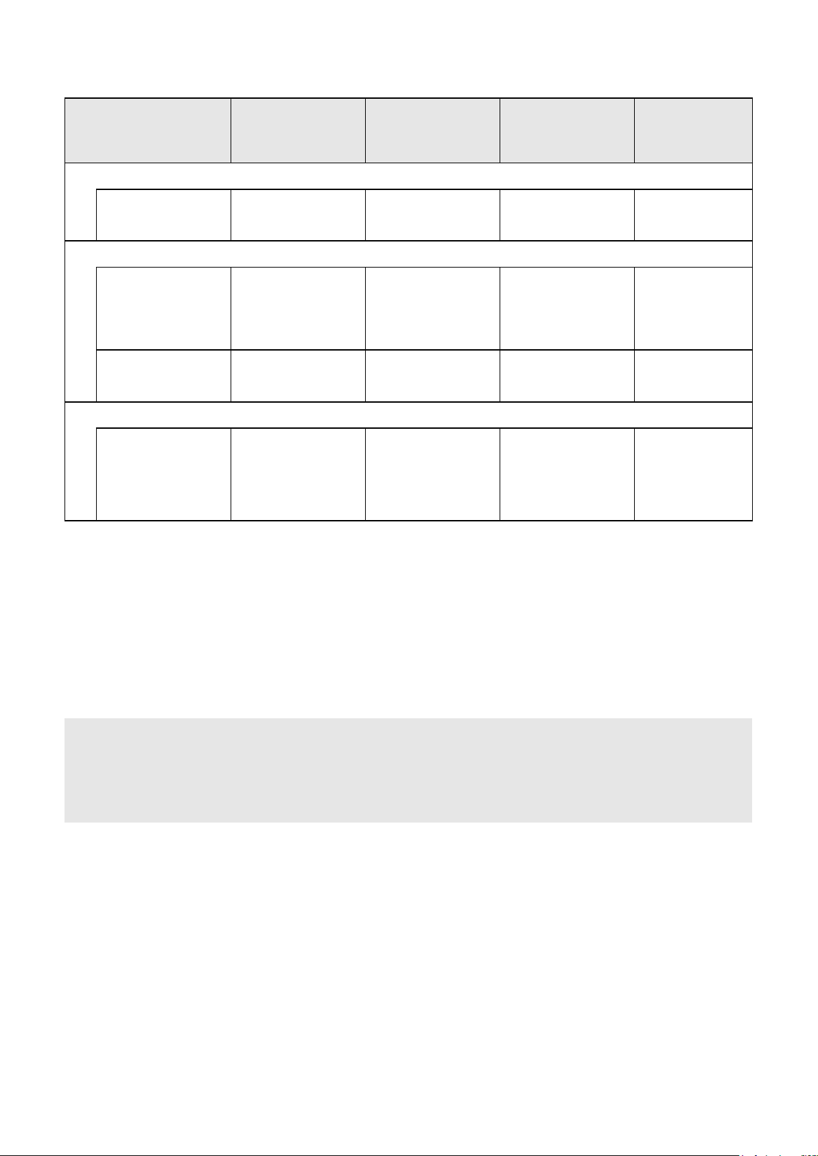
Information about Icom՚s D-STAR transceivers compatible with the DV Gateway function
The following table shows documents describing the DV Gateway function, as well as software and applications available for each transceiver. (As of August 2025)
ID-51A/E PLUS2
ID-31A/E PLUS
ID-4100A/E IC-705 IC-905 IC-9700
ID-4100A/ID-4100E
About the DV Gateway
function
ADVANCED MANUAL
Section 15
ABOUT THE DV
GATEWAY FUNCTION
Descriptions
ID-52A/E PLUS ID-52A/E ID-50A/E
About the DV Gateway function
(Function guide common to the above transceivers)
Internal Gateway function
Wireless LAN N/A N/A N/A N/A N/A
Wired LAN N/A N/A N/A N/A N/A N/A
Gateway function (External)
Transceiver connector
type
Type-C Micro-B Type-C
DATA jack
[DATA]
DATA jack
[DATA]
(1) RS-MS3W (For Windows PCs)
User-supplied
Cables
for USB connection
Supplied USB cable
(Type-A to Type-C)
USB cable
(Micro-B to Type-A)
OPC-2418
(Micro-B to Type-C)
Supplied USB cable
(Type-A to Type-C)
OPC-2350LU
1
*
OPC-2350LU*
1
(Micro-B to Type-A)
(Micro-B to Type-C)
(2) RS-MS3A (For Android devices)
USB connection
*
2
*
2
*
2
OPC-2417
Cables
for USB connection
Bluetooth connection
User-supplied
USB cable
*
3
*
4
(Micro-B to Micro-B)
OPC-2418
User-supplied
USB cable*
3
OPC-2350LU*
1
OPC-2350LU*
(Micro-B to Type-C)
N/A N/A N/A N/A N/A N/A N/A
(Micro-B to Micro-B)
1
(Micro-B to Type-C)
(3) RS-MS3I (For iOS devices)
Bluetooth connection
*
5
N/A N/A N/A N/A N/A N/A N/A
ADVANCED MANUAL
Section 12
ABOUT THE DV
GATEWAY FUNCTION
Micro-B Type-C
User-supplied
USB cable
OPC-2418
2
*
OPC-2417
OPC-2418
User-supplied
USB cable
User-supplied
USB cable
ADVANCED MANUAL
Section 12
ABOUT THE DV
GATEWAY FUNCTION
N/A N/A
DATA jack
[DATA]
OPC-2350LU
*
2
3
*
OPC-2350LU*
1
*
1
: Applicable
N/A: Not Applicable
*1 If your device only has a USB Type-C port, you will need to purchase a commercially available
USB On-The-Go (OTG) adapter to use the OPC-2350LU.
OPC-2350LU + Supplied cable (Mini-B to Type-A) + USB OTG adapter (Type-A to Type-C)
(For your reference)
Type-A Micro-B Type-C
*2 Usable only when the RS-MS3A version is 1.31 or later.
*3 The OPC-2418 cannot be used.
*4 Usable only when the RS-MS3A version is 1.40 or later.
*5 Usableonlywhenthetransceiver՚sMainCPU(CPUM)versionis1.10orlater.
A7603-11EXAug. 2025
 Loading...