

Page 1

To update the repeater list,
click here!
ADVANCED INSTRUCTIONS
VHF/UHF TRANSCEIVER
ID-51A
ID-51E
INTRODUCTION
1 ACCESSORY ATTACHMENT
2 USING A MICROSD CARD
3 PANEL DESCRIPTION
4 BATTERY CHARGING
5 BASIC OPERATION
6 BC RADIO OPERATION
7 D-STAR INTRODUCTION
8 D-STAR OPERATION <BASIC>
9 D-STAR OPERATION <ADVANCED>
10 GPS/GPS-A OPERATION
Instructions for advanced operations and additional
details are described in this manual.
See the Basic instruction manual to begin D-STAR,
especially for new users.
11 VOICE MEMORY FUNCTION
12 MEMORY CHANNEL PROGRAMMING
13 SCAN OPERATION
14 PRIORITY WATCH
15 REPEATER AND DUPLEX OPERATIONS
16 MENU SCREEN
17 OTHER FUNCTIONS
18 OPTIONS
19 SPECIFICATIONS
TROUBLESHOOTING
INDEX
Page 2
INTRODUCTION
15
REPEATER AND DUPLEX OPERATIONS
15-4
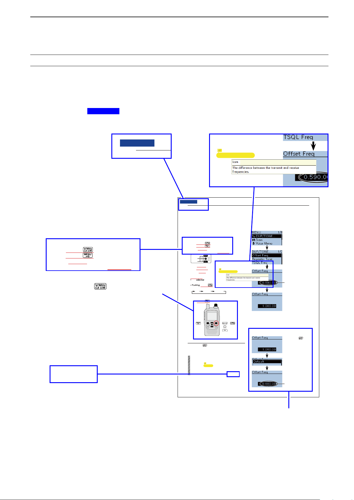
� Duplex operation
The Duplex operation shifts the transmit frequency
up or down from the receive frequency by an offset
amount.
D Setting the frequency offset
Push [V/MHz] q to select the VFO mode.
Push [MENU] w .
Push D-pad( e ) to select the root item (“DUP/
TONE...”), and then push D-pad(Ent).
Push D-pad( r ) to select the “Offset Freq,” and then
push D-pad(Ent).
Rotate [DIAL] to set the frequency offset to be- t
tween 0.000.00 and 59.99500 MHz, and then push
D-pad(Ent). (Setting example: 1.000.00 MHz)
The tuning step in the VFO mode is used when
setting the frequency offset.
[V/MHz]
toggles the tuning digit, as shown
below.
TS* 1 MHz 10 MHz
* The frequency changes according to the preset tuning
steps. (p. 5-6)
Push [MENU] y to exit the [MENU] screen.
To reset to the default value.
Push [QUICK] in step t as described abov e, then
push D-pad(Ent) to reset to the default value.
The current frequency
offset
Rotate [DIAL], then
push D-pad(Ent).
Push [QUICK]
Push D-pad(Ent)
[DIAL]
The current frequency
offset
D-pad
( )
(Ent)
NOTE:
• The frequency offset cannot be changed in the DR
mode.
• The Auto repeater function uses the preset fre-
quency offset. Depending on the frequency offset
value, the off band indication, “OFF , ” appears on
the display when [PTT] is pushed. (p. 15-5)
Previous view
The current frequency
offset
Previous view
15
REPEATER AND DUPLEX OPERATIONS
� Duplex operation
The Duplex operation shifts the transmit frequency
up or down from the receive frequency by an offset
amount.
D Setting the frequency offset
Push [V/MHz] q to select the VFO mode.
Push [MENU] w .
Push D-pad( e ) to select the root item (“DUP/
TONE...”), and then push D-pad(Ent).
Previous view
About these Advanced Instructions (PDF format)
These Advanced Instructions describe the details of the ID-51A/E features. This PDF formatted manual provides
you with convenient functions, as follows.
Move to the previously read page.
Click
Previous view
at the left top on an
each page, to move back to the previously read page.
Shows the location of keys
When the cursor is moved over a term with a red
underline, a red circle appears around the appropriate key(s) on the figure of the transceiver.
Shows a term description
When the mouse cursor is moved over a term which
is highlighted in yellow, the description of the term is
displayed.
Example: When the cursor is moved over
[V/MHz] in the description, a
red circle appears around the appropriate key(s).
Move to the page, if clicked.
Icom, Icom Inc. and the Icom logo are registered trademarks of Icom Incorporated (Japan) in Japan, the United States, the
United Kingdom, Germany, France, Spain, Russia and/or other countries.
Adobe and Adobe Reader are registered trademark of Adobe Systems Incorporated.
All other products or brands are registered trademarks or trademarks of their respective holders.
(p. 15-5)
The screen shots at the right column, correspond
to the operating instructions and procedures
shows both setting and operating example.
i
Page 3
INTRODUCTION
Previous view
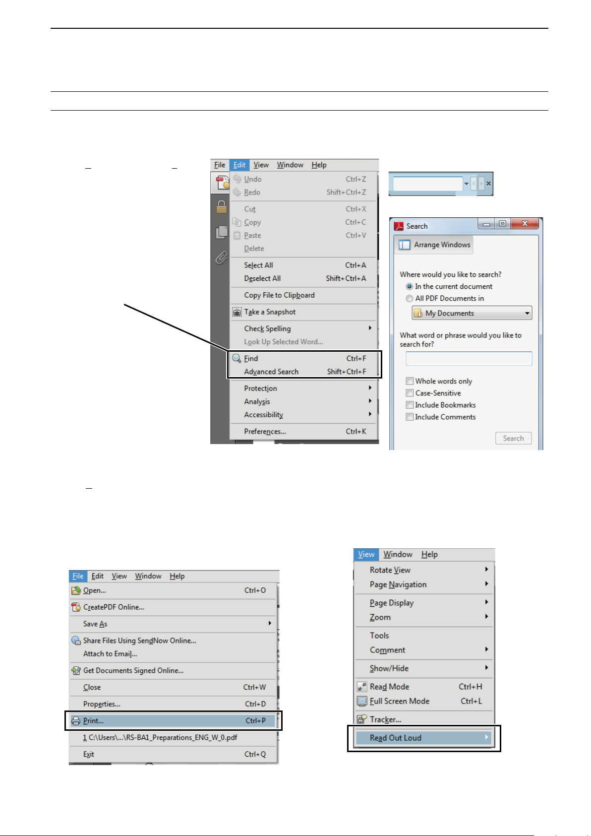
Functions and features of Adobe® Reader
The following functions and features can be used with Adobe® Reader®.
• Keyword search
Click “Find (Ctrl+F)” or “Advanced
Search (Shift+Ctrl+F)” in the Edit
menu to open the search screen.
This is convenient when search-
ing for a particular word or phrase
in this manual.
* The menu screen may differ, depend-
ing on the Adobe
Click to open the find or search
screen or advanced search screen.
®
Reader® version.
®
• Find screen
• Advanced search screen
• Printing out the desired pages.
Click “Print (P)” in File menu, and then select the pa-
per size and page numbers you want to print.
* The printing setup may differ, depending on the
printer. Refer to your printer’s instruction manual
for details.
* Select "A4" size to print out the page in the equal-
ized size.
• Read Out Loud feature.
The Read Out Loud feature reads aloud the text in
this Instruction Manual.
Refer to the Adobe
®
Reader® Help for the details.
( This feature may not be usable, depending on your
PC environment including the operating system.)
*The screen may differ, depending on the Adobe® Reader® version.
ii
Page 4

Section 1
Previous view
ACCESSORY ATTACHMENT
Antenna ■ .............................................................................. 1-2
Battery pack ■ ....................................................................... 1-2
Belt clip ■ ............................................................................... 1-3
Hand strap ■ .......................................................................... 1-3
1-1
Page 5
ACCESSORY ATTACHMENT
q
w
q
q
w
Previous view
1
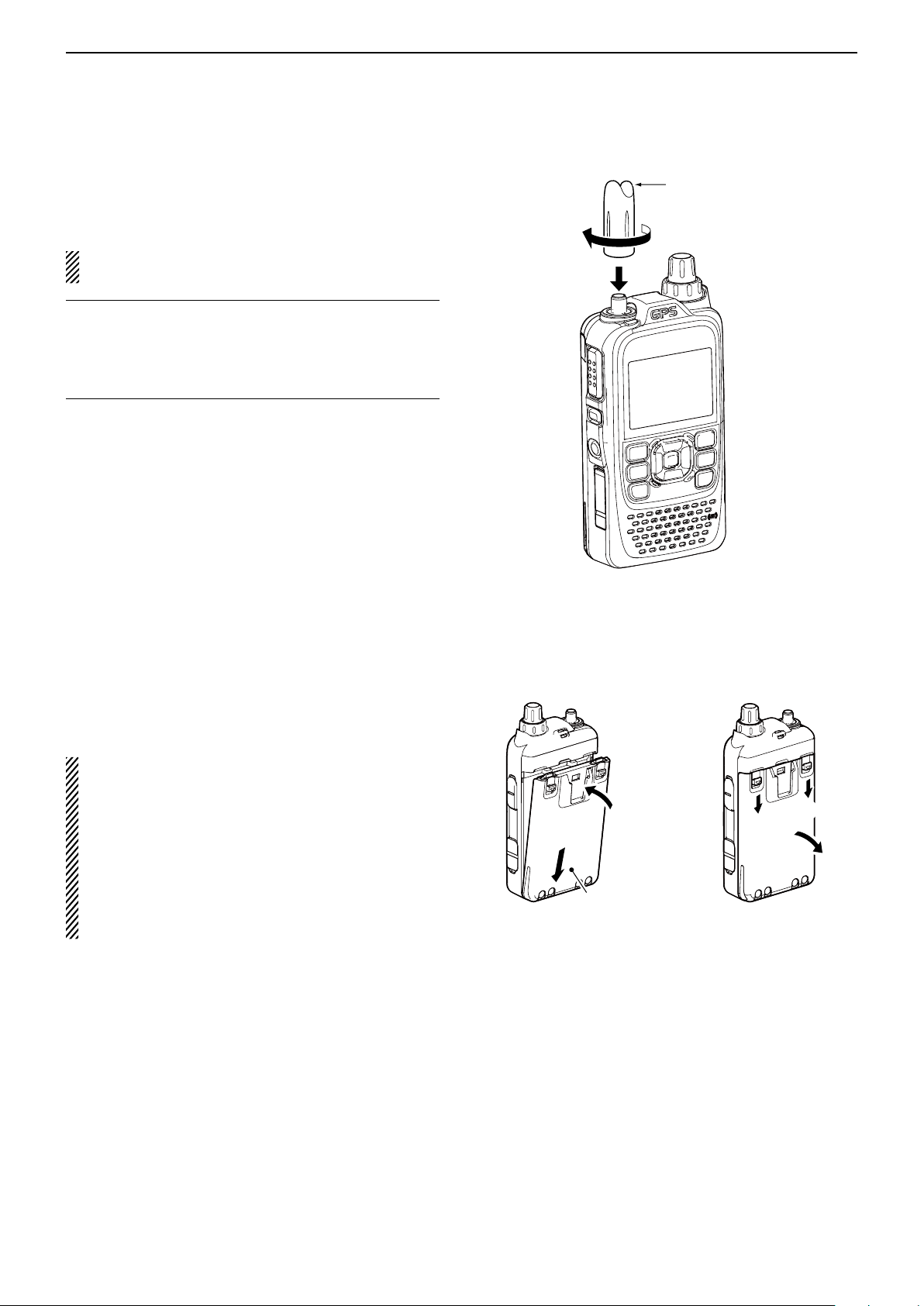
■ Antenna
Insert the antenna connector into the antenna base
and tighten the antenna.
NEVER carry the transceiver by holding only the an-
tenna.
For your information ✓
Third-party antennas may increase transceiver performance. An optional AD-92SMA a n t e n n a c o n n e c t o r
a d a p t e r is available to connect an antenna that has a
BNC connector. (p. 18-3)
Antenna
Battery pack ■
To attach or detach the battery pack:
Attach or detach the battery pack or battery case, as
illustrated to the right.
See page 4-2 for details of the battery pack.
Even when the transceiver power is OFF, a small
current still flows in the radio. Remove the battery
pack or case from the transceiver when not using it
for a long time. Otherwise, the battery pack or installed batteries will become exhausted.
The battery protection function automatically sets
transceiver to Low1 power (0.5 W) when the temperature is around 0°C (+32°F) or below. In this case,
transmit power selections (High, Mid and Low2) are
disabled.
To attach To detach
Battery pack
or battery case
Illustration shows the
battery pack is attached.
1-2
Page 6
ACCESSORY ATTACHMENT
q
w
Tab
Previous view
1
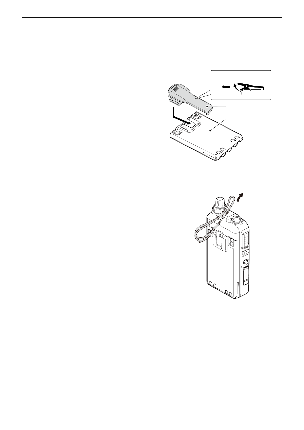
Belt clip ■
To attach the belt clip:
Remove the battery pack from the transceiver, if it is q
attached. (p. 1-2)
Slide the belt clip in the direction of the arrow until the w
belt clip locks in place, and makes a ‘click’ sound.
To attach To detach
To detach the belt clip:
Remove the battery pack from the transceiver, if it is q
attached. (p. 1-2)
Lift the tab up ( w q), and slide the belt clip in the direc-
tion of the arrow (w).
■ Hand strap
To facilitate carrying the transceiver, slide the hand
strap through the loop on the top of the rear panel, as
illustrated to the right.
Belt clip
Battery pack
or battery case
Hand strap
1-3
Page 7

Section 2
Previous view
USING A microSD CARD
About the microSD card ■ ...................................... 2-2
Saving data onto the microSD card ■ ..................... 2-2
Inserting the microSD card ■ .................................. 2-3
Formatting the microSD card D .......................... 2-3
Removing the microSD card ■ ................................ 2-4
Save setting data onto a microSD card ■ ............... 2-5
Save with a different file name ■ ............................. 2-7
Loading the saved data files that are on the ■
microSD card ....................................................... 2-9
Backup the data stored on the microSD card ■
onto a PC .......................................................... 2-11
About the microSD card’s folder composition D 2-11
Make a backup file on your PC D ...................... 2-12
Updating the repeater list ■ .................................. 2-13
2-1
Page 8
USING A microSD CARD
Previous view
2
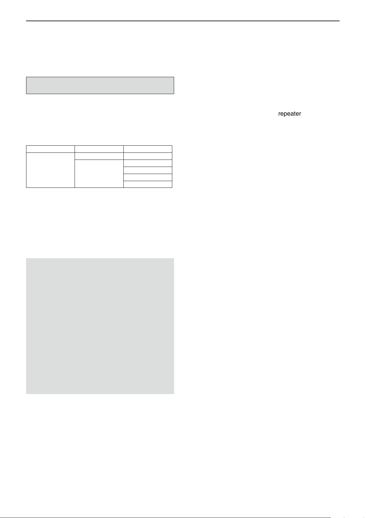
■ About the microSD card
The microSD and microSDHC cards are not available
from Icom. Purchase locally.
A microSD card of up to 2 GB or a microSDHC of up to
32 GB, can be used with the ID-51A/E.
Icom has checked the operation with the following microSD and microSDHC cards.
(As of November 2012)
Brand Type Memory size
microSD 2 GB
SanDisk
• The above list does not guarantee the card’s performance.
• Through the rest of this document, the microSD card
and a microSDHC card are simply called microSD
cards.
• Icom recommends that you format all microSD cards
to be used with the ID-51A/E, even preformatted microSD cards for PCs or other uses.
®
microSDHC
4 GB
8 GB
16 GB
32 GB
■ Saving data onto the microSD card
The following data can be stored onto the card:
• Data settings of the transceiver
Memory channel contents, and repeater lists stored in
the transceiver.
• Communication contents
The transmitted and received audio.
• Communication log
The communication and receive history log.
•
Automatic answering voice audio for the DV mode
Voice audio to use with the Auto Reply function in the
DV Mode.
• V
oice audio for the Voice TX function
Voice audio to use with the Voice TX function.
• Position data from the GPS receiver
Position and time data from a GPS receiver, that is in a
log file as a route.
NOTE:
• Read the instructions of the microSD card thoroughly before use.
• NEVER remove the microSD card, detach the bat-
tery pack/case, or power OFF the transceiver, while
reading or writing data to or from the microSD card,
or during cloning. It will cause the data to be corrupted or damage the card.
• NEVER drop, or apply vibration or impact to the mi-
croSD card. This will cause the data to be corrupted
or damage the card.
• The microSD card will get warm if used continuously
for a long period of time.
• A microSD card has a certain lifetime, so data reading or writing will not be possible when using it over
a long time period.
• Icom will not be responsible for any damage caused
by data corruption of a microSD card.
•
Voice Recorder
The microphone audio.
2-2
Page 9
USING A microSD CARD
D-pad
(�)
(Ent)
Previous view
2
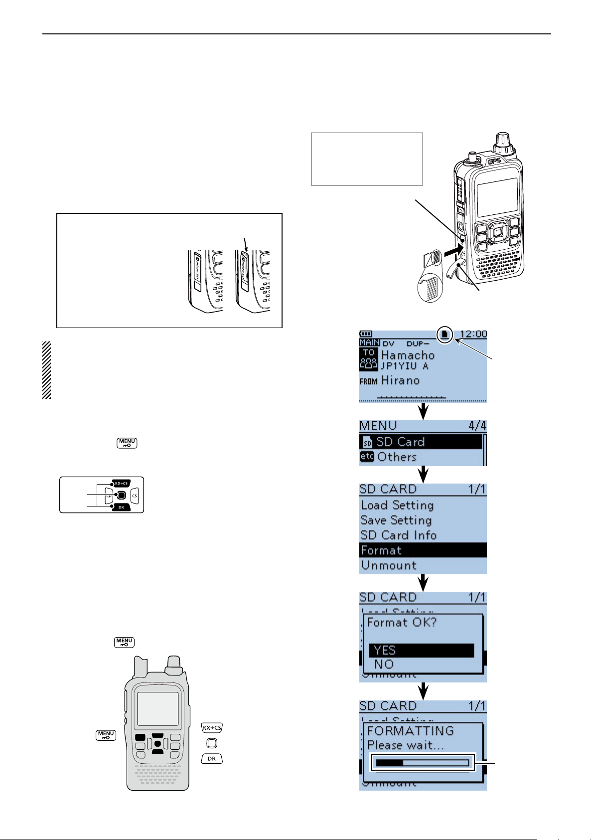
■ Inserting the microSD card
Turn OFF the transceiver. q
Lift OFF the [micro SD] slot cover on the side panel. w
With the terminals facing the front, insert the card e
into the slot until it locks in place, and makes a ‘click’
sound.
DO NOT touch the terminals.
Firmly close the [micro SD] slot cover. r
CAUTION:
After a microSD card is
Close the cover,
leaving no gap.
inserted, firmly close the
[micro SD] slot cover as
shown to the right.
Correct
Wrong
• If you use a brand new microSD card, format the
microSD card, by doing the following steps.
• Formatting a card erases all its data. Before for-
matting any programmed card, make a backup file
onto your PC.
Formatting the microSD card D
Turn ON the transceiver. q
Push [MENU] w .
Push D-pad( e ) to select the root item (“SD Card”),
and then push D-pad(Ent).
NEVER forcibly or inversely insert the card.
It will damage the card
and/or the slot.
[micro SD] slot
microSD card
Terminals facing
the front
Slot cover
Appears when
the microSD
card is inserted.
Push D-pad( r ) to select “Format,” and then push D-
pad(Ent).
• The conrmation screen “Format OK?” appears.
Push D-pad( t ) to select “YES,” and then push D-
pad(Ent) to format.
• The formatting starts and the display shows the format-
• NEVER turn OFF the power while formatting.
After formatting, the display automatically returns to y
the SD CARD menu.
Push [MENU] u to exit the MENU screen.
ting progress.
Shows the
formatting
progress
2-3
Page 10
USING A microSD CARD
D-pad
(�)
(Ent)
Previous view
2
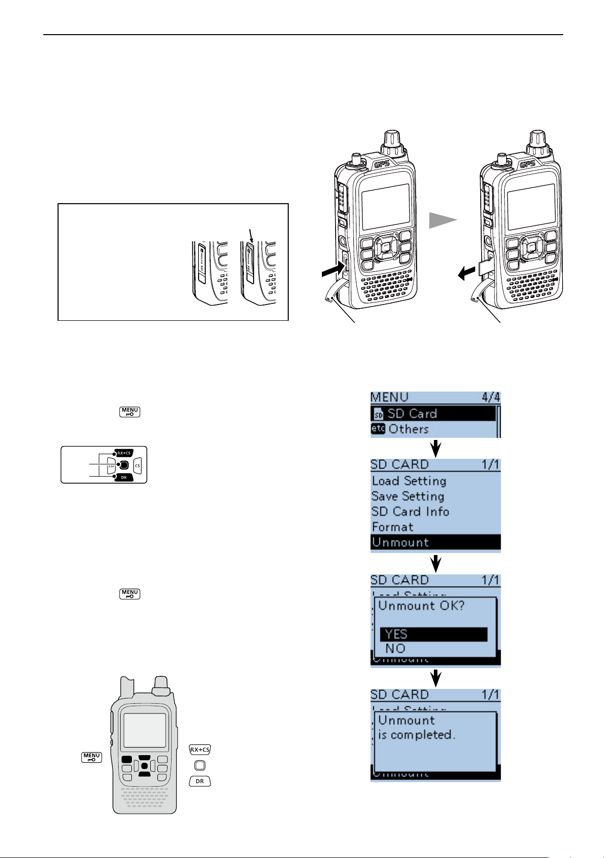
■ Removing the microSD card
Turn OFF the power. q
Lift OFF the [micro SD] slot cover on the side panel. w
Push in the microSD card until a click sounds, and e
then carefully pull it out.
• DO NOT touch the terminals.
Firmly close the [micro SD] slot cover. r
CAUTION:
After a microSD card is
Close the cover,
leaving no gap.
inserted, firmly close the
[micro SD] slot cover as
shown to the right.
Correct
Wrong
If removing the microSD card while the transceiver’s
power is ON, by doing the following steps.
Push [MENU] q .
Push D-pad( w ) to select the root item (“SD Card”),
and then push D-pad(Ent).
Push D-pad( e ) to select “Unmount,” and then push
D-pad(Ent).
• The conrmation screen “Unmount OK?” appears.
Push D-pad( r ) to select “YES,” then push D-pad(Ent)
to unmount.
When the unmounting is completed, “Unmount is t
completed.” is displayed, then the screen automatically returns to the SD CARD menu.
Push [MENU] y to exit the MENU screen.
Lift OFF the [micro SD] slot cover on the side panel. u
Push in the microSD card until a click sounds, and i
then carefully pull it out.
• DO NOT touch the terminals.
Firmly close the [micro SD] slot cover. o
Slot cover Slot cover
Push the microSD
card until a click
sounds.
Pull the microSD
card out.
2-4
Page 11
USING A microSD CARD
D-pad
(�)
(Ent)
Previous view
2
■ Save setting data onto a microSD card
Memory channels, item settings in the menu screen,
and repeater lists can be saved on the microSD card.
Saving data settings on the microSD card allows you
to easily restore the transceiver to its previous settings,
even if an all reset is performed.
For your information ✓
Data settings are saved in the “icf” file format that is
used in the CS-51 cloning software.
The saved data on the microSD card can be copied
onto a PC and edited by the cloning software.
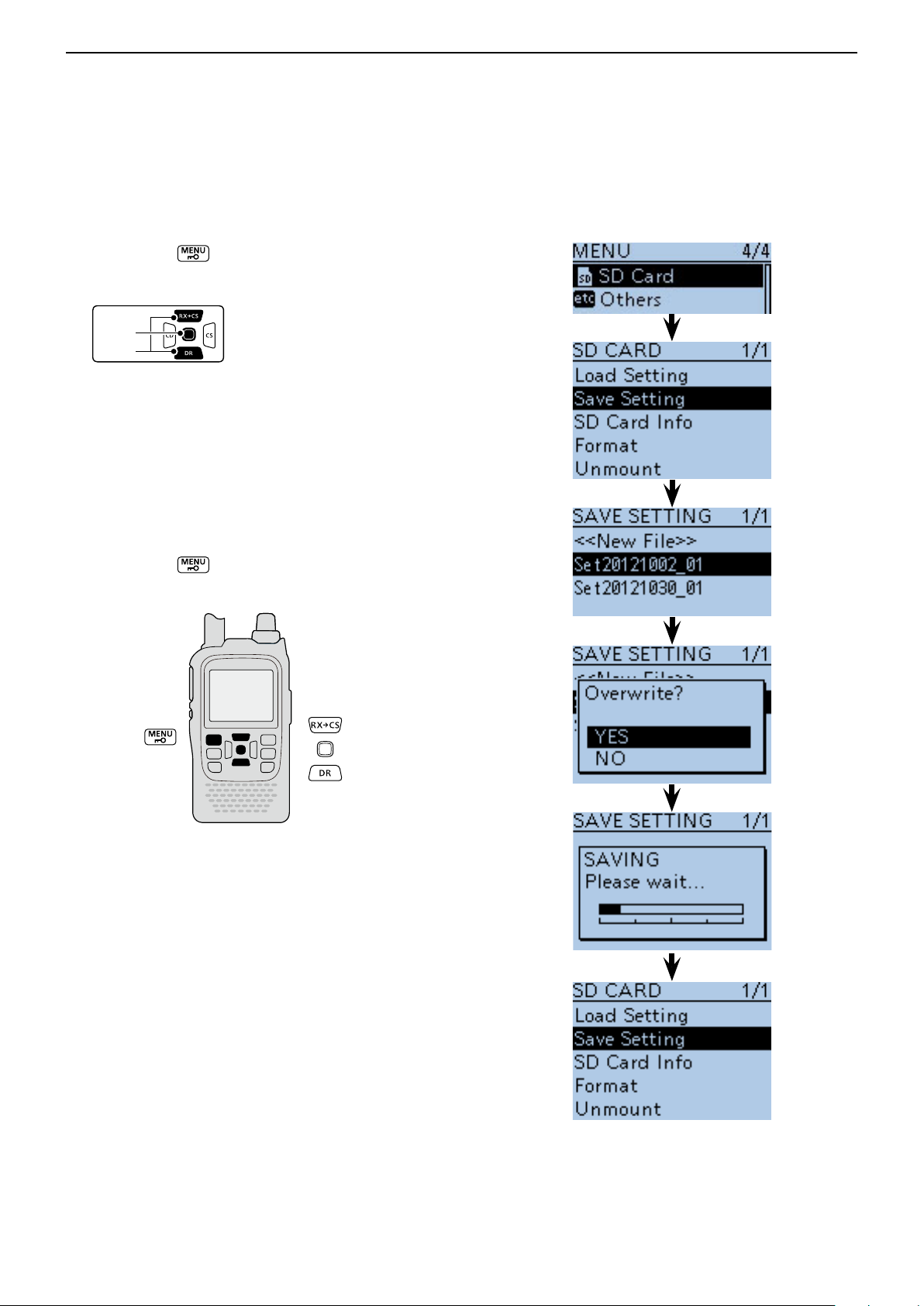
Data settings can be saved as a new file or to overwrite
an older file.
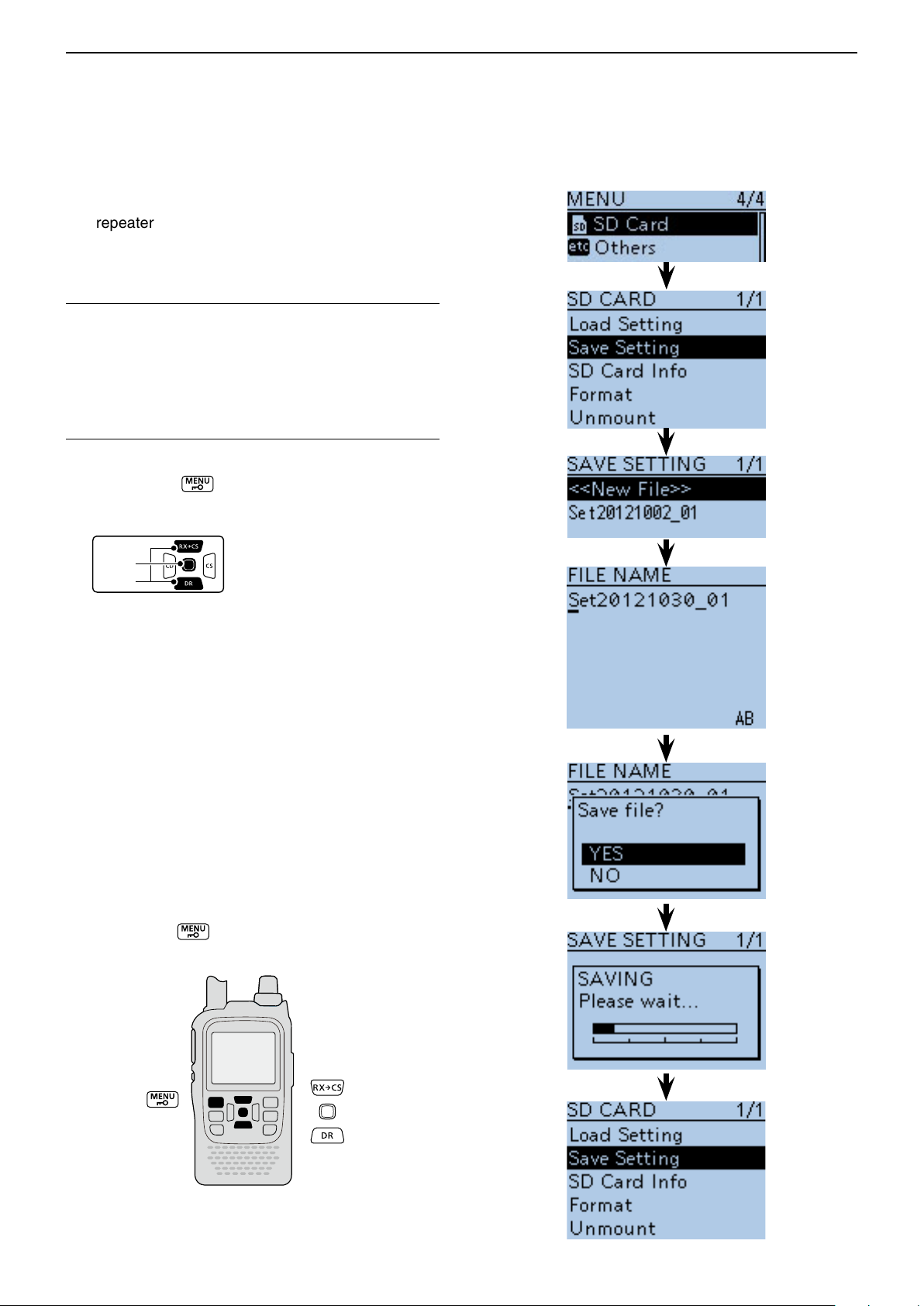
Saved as a new file
Push [MENU] q .
Push D-pad( w ) to select the root item (“SD Card”),
and then push D-pad(Ent).
Push D-pad( e ) to select “Save Setting,” and then
push D-pad(Ent).
Push D-pad( r ) to select “<<New File>>,” and then
push D-pad(Ent).
• The FILE NAME screen is displayed.
• The le name is automatically named in the following
manner; Setyyyymmdd_xx (yyyy: Year, mm: month, dd:
day, xx: serial number)
Example: If a 2nd file is saved on October 30, 2012, the
file is named “Set20121030_02”.
• If you want to change the le name, see “Save with a different file name” (p. 2-7).
Push D-pad(Ent) to save the file name. t
• The conrmation screen “Save le?” appears.
Push D-pad( y ) to select “YES,” then push D-pad(Ent)
to save.
• While saving, a progress bar is displayed, then the “SD
CARD” screen is displayed after the save is completed.
Push [MENU] u to exit the MENU screen.
2-5
Page 12
USING A microSD CARD
D-pad
(�)
(Ent)
Previous view
2
Save setting data onto a microSD card (Continued) ■
Overwriting a file
(Example: Overwriting the “Set20121002_01”)
Push [MENU] q .
Push D-pad( w ) to select the root item (“SD Card”),
and then push D-pad(Ent).
Push D-pad( e ) to select “Save Setting,” and then
push D-pad(Ent).
Push D-pad( r ) to select the desired file to be over-
written, and then push D-pad(Ent).
(Example: Selecting “Set20121002_01”)
• The conrmation screen “Overwrite?” appears.
Push D-pad( t ) to select “YES,” and then push D-
pad(Ent) to overwrite the setting file.
• While saving, a progress bar is displayed, then the “SD
CARD” screen is displayed after the save is completed.
Push [MENU] y to exit the MENU screen.
2-6
Page 13
USING A microSD CARD
D-pad
(�)
(Ent)
Previous view
2
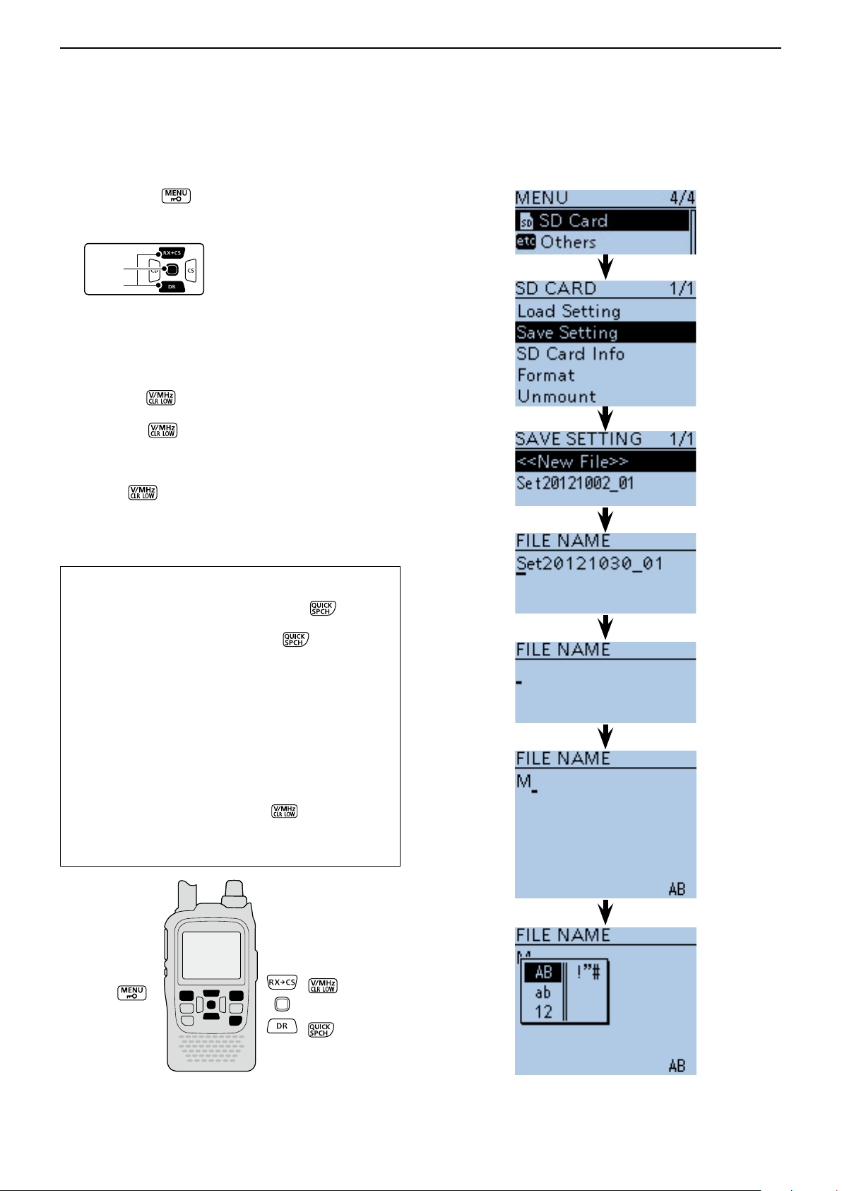
■ Save with a different file name
Push [MENU] q .
Push D-pad( w ) to select the root item (“SD Card”),
and then push D-pad(Ent).
Push D-pad( e ) to select “Save Setting,” and then
push D-pad(Ent).
Push D-pad( r ) to select “<<New File>>,” and then
push D-pad(Ent).
• The FILE NAME screen is displayed.
Push [CLR] t to delete the previously programmed
character.
• Push [CLR]
or number.
When the cursor does not select a character, the previous character is deleted.
If [CLR]
ed.
Rotate [DIAL] to select a desired character. y
• The selected character blinks.
to delete the selected character, symbol
is held down, all the characters are delet-
About text entry
• Push D-pad() to move the cursor backward or forward.
• While selecting a character, push [QUICK]
the character to a upper case or lower case letter.
• While selecting a digit, push [QUICK]
put mode selection window.
- Push D-pad() to select the desired Upper case let-
ters, Lower case letters, Numbers or Symbols.
- To enter symbols, select “!”#,” and then push D-pad(Ent)
to open the symbol character selection window. Rotate
[DIAL] to select the desired symbol character, and then
push D-pad(Ent).
• Move the cursor, then rotate [DIAL] to insert a character.
• A space can be selected in any input mode selected.
• Push D-pad() to enter a space.
• If you make a mistake, push [CLR]
lected character, or hold down [CLR] to continuously erase
the characters, first to the right, and then to the left of the
cursor.
to change
to open the in-
to delete the se-
Input mode selection
Continued on the next page ☞
2-7
window
Page 14
USING A microSD CARD
D-pad
(�)
(Ent)
Previous view
2
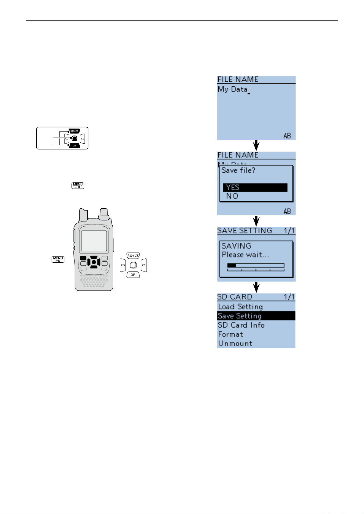
Save with a different file name (Continued) ■
Push D-pad( u ) to move the cursor to the second
digit.
Repeat steps i y and u to enter a name of up to
14-characters, including spaces.
(Example: My Data)
After entering the name, push D-pad(Ent). o
• After pushing D-pad(Ent), “Save le?” appears.
!0 Push D-pad() to select “YES,” and then push D-
pad(Ent) to save the setting file.
• While saving, a progress bar is displayed, then the “SD
CARD” screen appears after the save is completed.
!1 Push [MENU] to exit the MENU screen.
2-8
Page 15
USING A microSD CARD
D-pad
(�)
(Ent)
Previous view
2
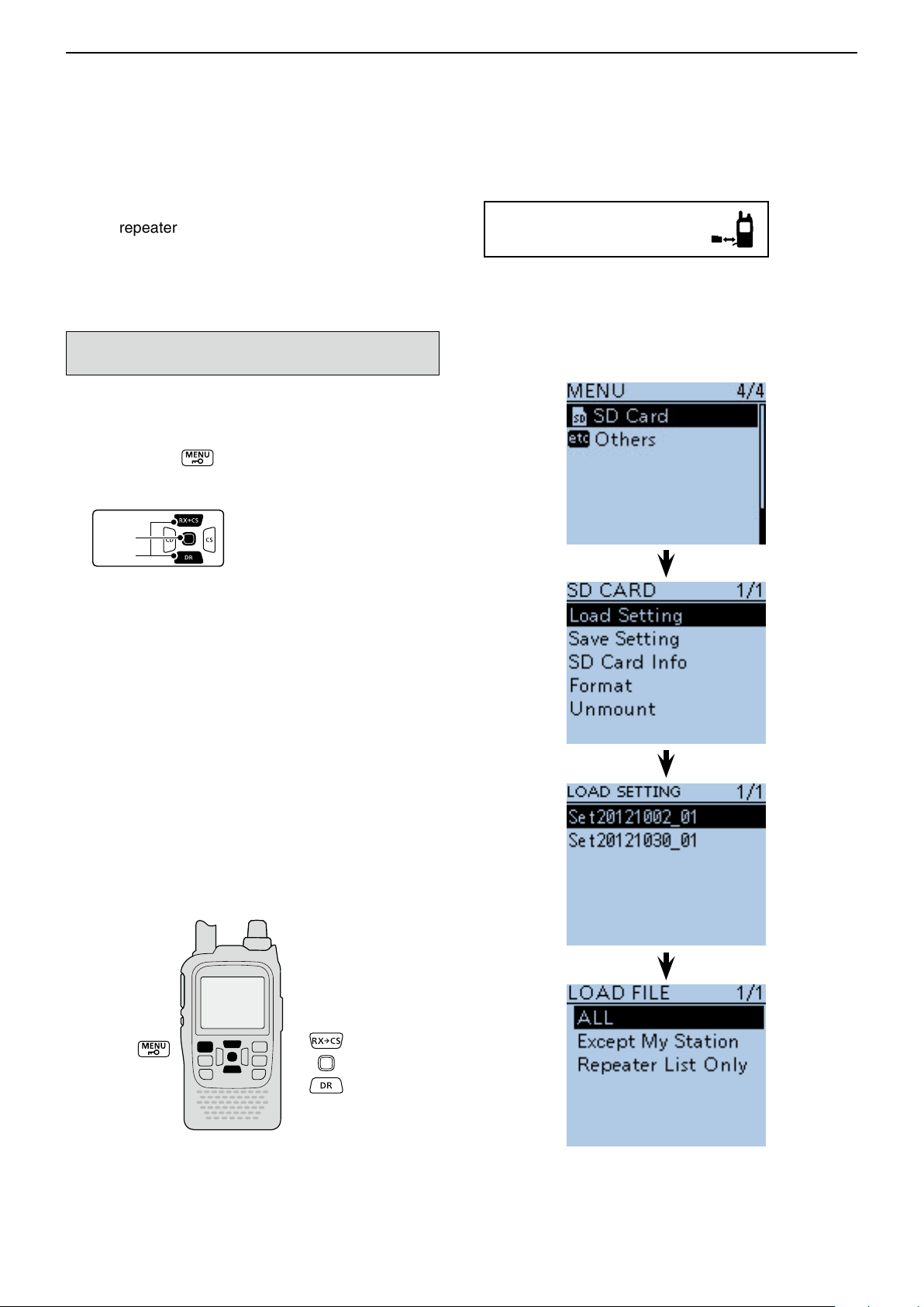
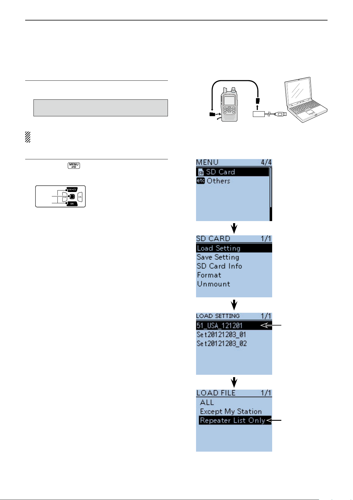
■ Loading the saved data les that are on the microSD card
The saved memory channels, item settings the in menu
list and repeater lists can be copied to the transceiver.
This function is convenient when copying the saved
data, such as memory channels, or repeater lists, to
another ID-51A/E and then operating with the same
data.
Saving the current data is recommended before loading other data in the transceiver.
(Example: Loading all the data in the
“Set20121002_01” file)
Push [MENU] q .
Push D-pad( w ) to select the root item (“SD Card”),
and then push D-pad(Ent).
Push D-pad( e ) to select “Load Setting,” and then
push D-pad(Ent).
Push D-pad( r ) to select the desired file to be load-
ed, and then push D-pad(Ent).
(Example: Selecting “Set20121002_01”)
• The LOAD FILE screen appears.
Push D-pad( t ) to select the desired loading con-
tent, as shown below.
• ALL:
Loads all memory channels, item settings in the menu
list and the repeater list into the transceiver.
• Except My Station:
Loads all memory channels, item settings in the menu
list except MY call signs and the repeater list into the
transceiver.
• Repeater List Only:
Loads only the repeater list into the transceiver.
(☞ Continued on the next page)
To update the repeater list,
click here!
2-9
Page 16
USING A microSD CARD
D-pad
(�)
(Ent)
Previous view
2
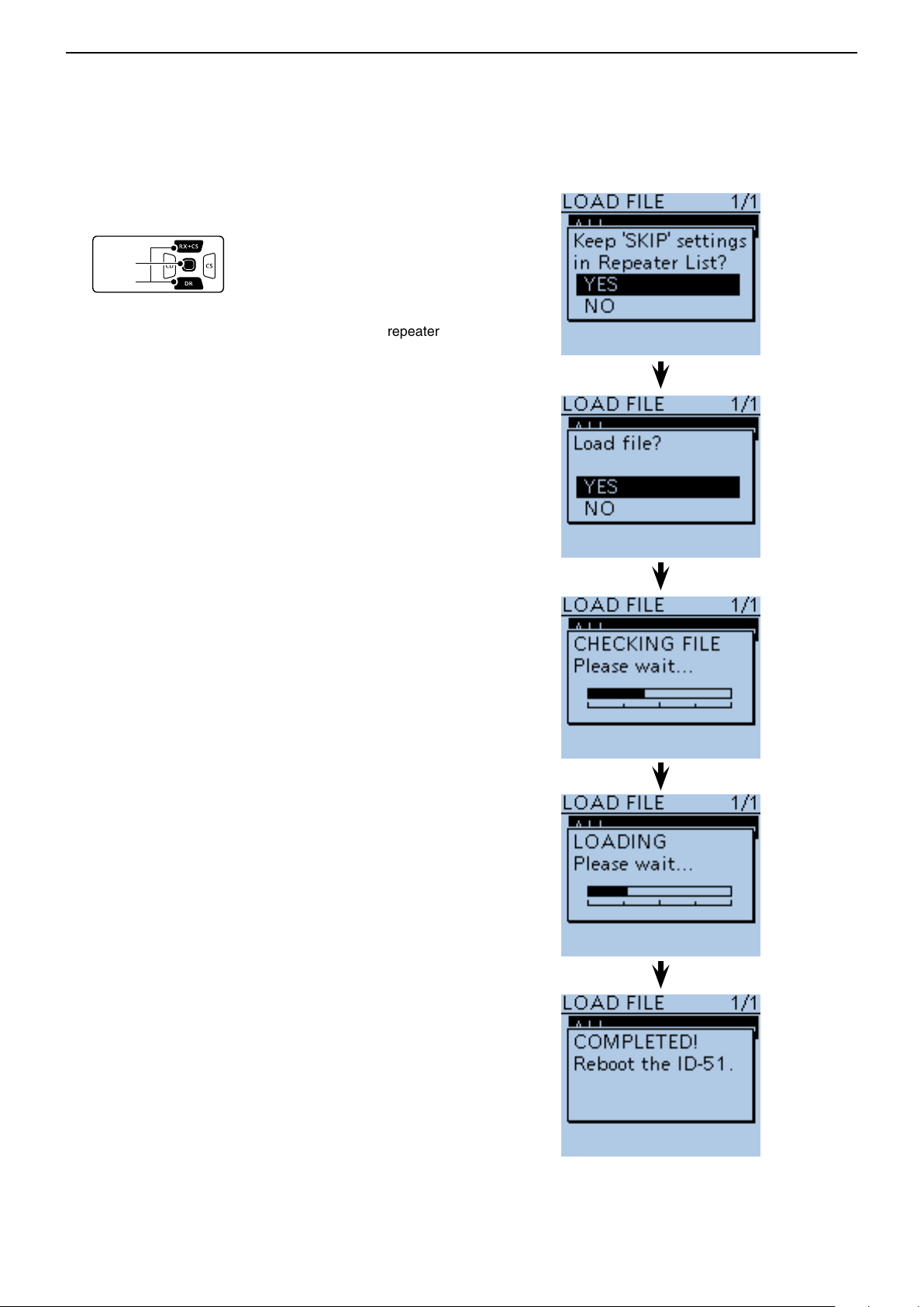
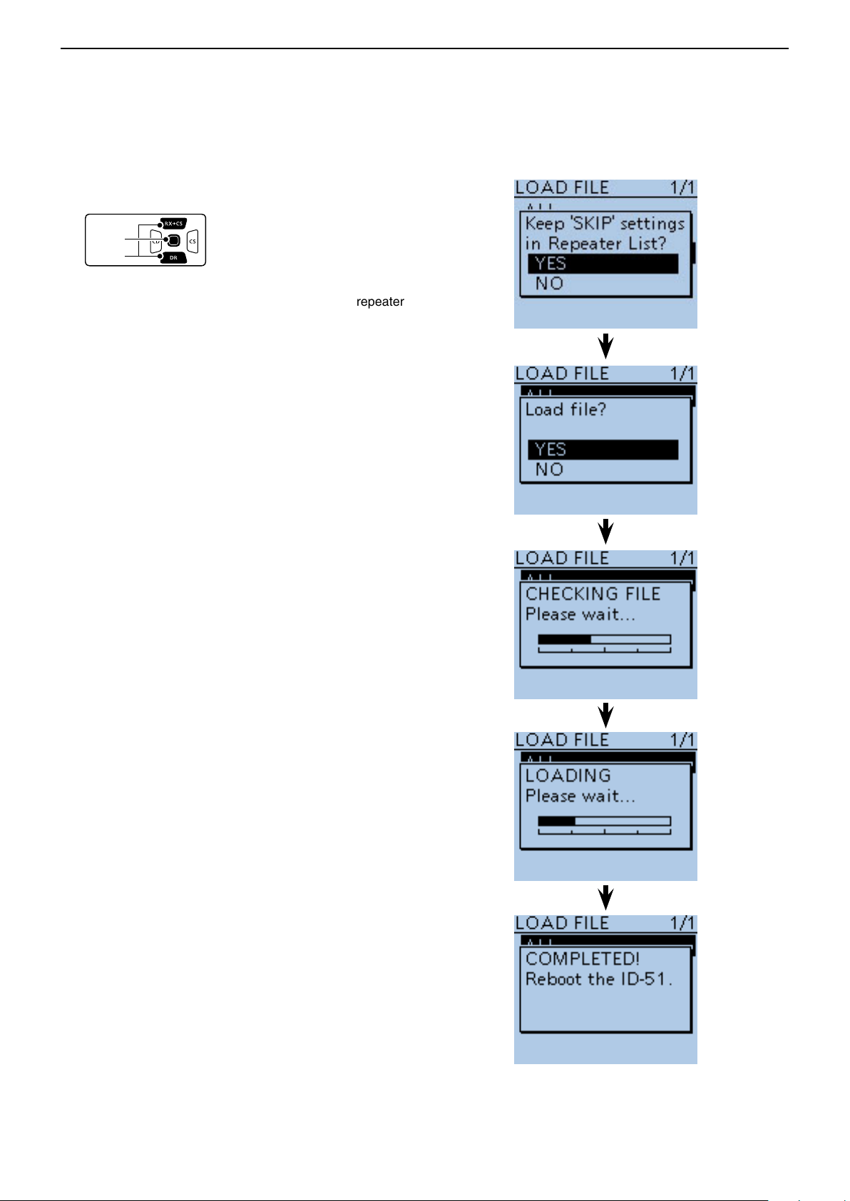
Loading the saved settings file that are on the microSD card (Continued) ■
Push D-pad(Ent) to select the file, and then the “Keep y
'SKIP' settings in Repeater List?” appears.
Push D-pad( u ) to select “YES” or “NO.”
• When “YES” is selected, the skip settings of the repeater
list are retained. (p. 9-36)
Push D-pad(Ent), “Load le?” appears. i
Push D-pad( o ) to select “YES,” then push D-pad(Ent)
to start the file check.
• While checking the le, “CHECKING FILE” and a progress bar are displayed.
!0 After checking, settings data loading starts.
• While loading, “LOADING” and a progress bar are displayed.
!1 After loading, “COMPLETED!” appears.
To complete the loading, reboot the transceiver.
2-10
Page 17
USING A microSD CARD
Previous view
2
■ Backup the data stored on the microSD card onto a PC
A backup file allows easy restoring even if the setting
data in the microSD card is accidentally deleted.
Depending on your PC, a memory card reader (purchase locally) may be additionally required to read the
microSD card.
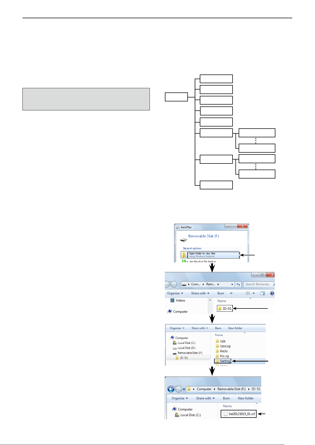
D About the microSD card’s folder compo-
sition
The folder composition in the microSD card is as follows:
ID-51 folder q
The folders created in the ID-51A/E are composed in
this ID-51 folder.
GPS folder w
GPS logging data is stored in the “log” format.
QsoLog e
QSO log data is stored in the “csv” format.
Reply folder r
Automatic reply data is stored in the “wav” format.
RxLog t
RX record log data is stored in the “csv” format.
Setting folder y
The transceiver’s setting data is stored in the “icf”
format.
Voice folder u
The recorded QSO audio date folders are created in
the Voice folder.
yyyymmdd folder i
Recorded audio file is stored in the “wav” format.
The folder name is automatically created in the fol-
lowing manner:
yyyymmdd (yyyy:Year, mm:month, dd:day)
VoiceRec o
The recorded Voice recorder audio date folders are
created in the VoiceRec folder.
!0 VoiceTx
Recorded voice audio data for the Voice TX function
is stored in the “wav” format.
Gps w
QsoLog e
ID-51 q
(Example: Selecting the setting data)
When the microSD card is inserted into the microSD card
drive of the PC or the microSD card reader (purchase locally), the screen appears as shown below.
Reply r
RxLog t
Setting y
Voice u yyyymmdd i
VoiceRec o
!0 VoiceTx
yyyymmdd i
yyyymmdd i
yyyymmdd i
Click
Click
Click
The setting
data
2-11
Page 18
USING A microSD CARD
Previous view
2
Backup the data stored on the microSD card onto a PC (Continued) ■
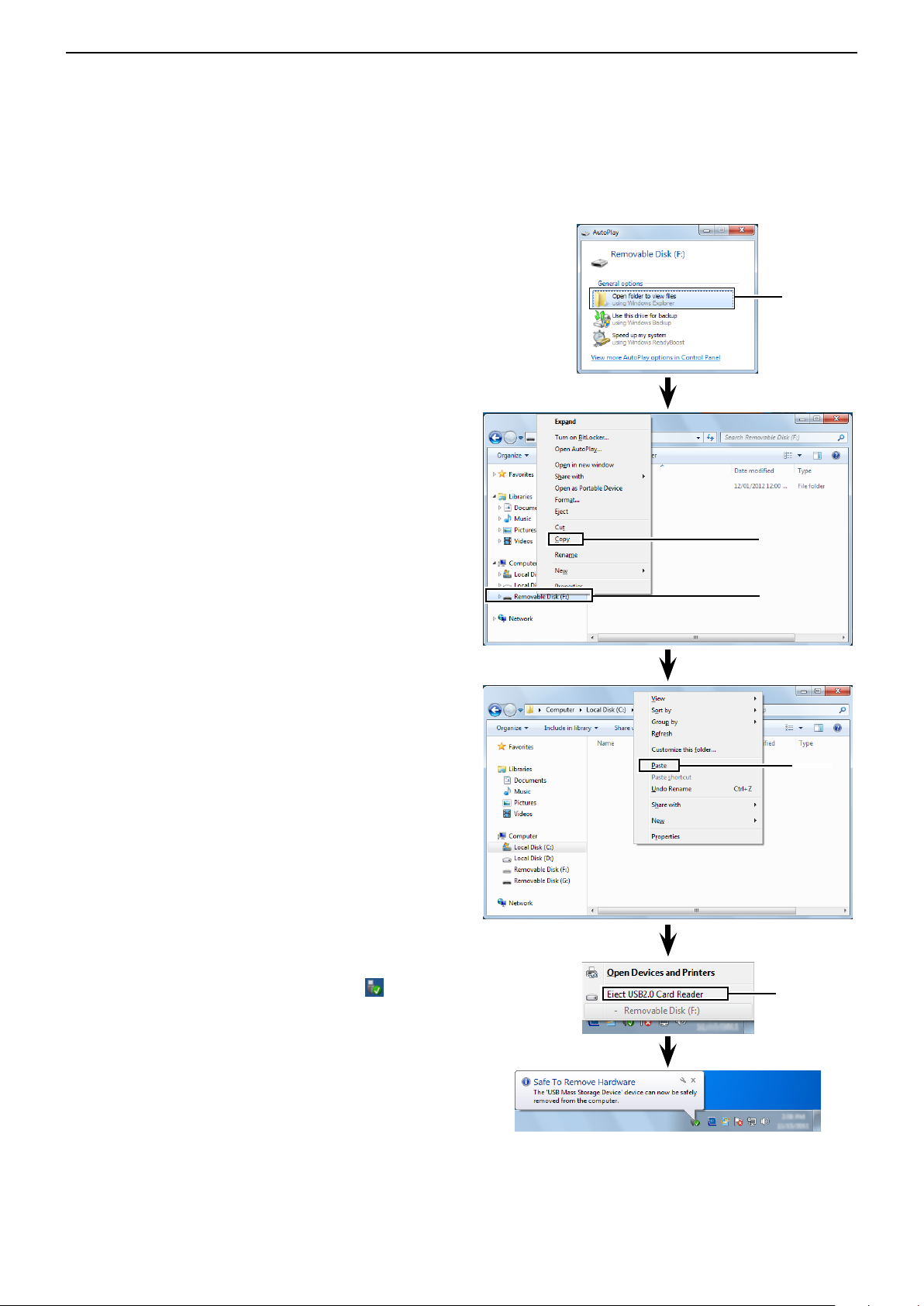
D Make a backup file on your PC
Windows 7 is used for these instructions.
Insert the microSD card into the microSD card drive q
on your PC.
• If no microSD card drive is built-in, connect a memory
card reader (purchase locally) and then insert the microSD card into it.
Click the “Open folder to view files” option to access w
the card.
Select “Removal disk” and right click. e
Click “Copy.” r
Click
Open the desired folder to copied to, the right click t
then click “Paste” to copy the data that is in the microSD card onto the hard disk.
(Example: Copying into the “Backup” folder in C
drive)
When removing the microSD card from the PC, click y
the microSD card icon in the task bar. (“ ” icon in
the screen shot as shown to the right.)
• The screen shot shows when a memory card reader is
connected.
Click
Right click
Click
Click
Remove the microSD card from the PC when “Safe u
To Remove Hardware” appears.
• The screen shot shows when a memory card reader is
connected.
2-12
Page 19
USING A microSD CARD
Previous view
2
■ Updating the repeater list
For easy operation, the repeater list is preloaded into
your transceiver.
This section describes how to manually update the repeater list using a microSD card.
The latest setting file can be downloaded from the Icom
website.
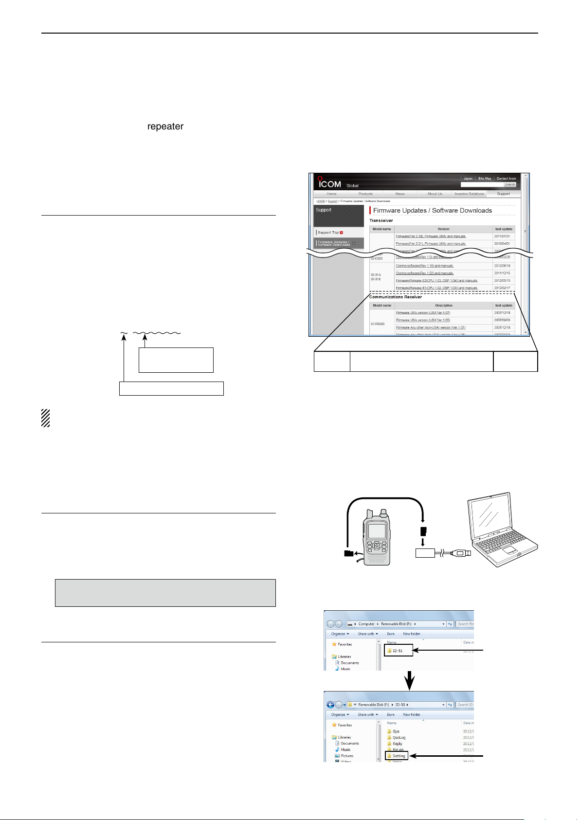
Downloading the latest setting file (ICF file)1.
q Access the following URL to download the latest
data.
http://www.icom.co.jp/world/support/download/firm/
index.html
• The latest settings le (ICF le) and repeater list (CSV;
Comma Separated Values file) are contained in the
downloaded ZIP file.
File Name: 51_U_121201.zip
Depending on the
updated file date.
Depending on the version.
ID-51A/E’s latest setting file is uploaded to
“Cloning software(Rev. MM) and manuals” in
the Icom website screen.
• The displayed contents may differ.
ID-51A
ID-51E
Cloning software(Rev. MM) and manuals
2012/12/MM
This instruction manual describes when the file
name is “51_U_121201.zip,” for example.
w Decompress the compressed file that is downloaded
from the Icom website.
“51_U_121201” folder will be created on the same
place where the downloaded file is saved.
Inserting the microSD card into a PC2.
e Insert the microSD card into the microSD card drive
on your PC.
• Icom recommends that you format all microSD
cards to be used with the ID-51A/E, even preformatted microSD cards for PCs or other uses.
See page 2-3 for details of inserting and removing
the microSD card.
Copying the latest ICF file to the microSD card3.
r Double-click the “51_U_121201” folder created on
the same place where the downloaded file is saved.
t Copy the ICF file (Example: “51_USA_121201.icf”)
in the folder to the “Setting” folder in the “ID-51” folder
of the microSD card.
microSD
card
Transceiver
PC
to the Card
reader
Click
Continued on the next page ☞
Click
2-13
Page 20
USING A microSD CARD
D-pad
(�)
(Ent)
Previous view
2
Updating the repeater list (Continued) ■
Inserting the microSD card4.
y Remove the microSD card from the PC, and insert
the card into the transceiver’s slot.
See page 2-3 for details of inserting and removing
the microSD card.
Saving the current data is recommended before
loading other data into the transceiver.
Updating the repeater list5.
u Push [MENU]
.
i Push D-pad() to select the root item (“SD Card”),
and then push D-pad(Ent).
o Push D-pad() to select “Load Setting,” and then
push D-pad(Ent).
!0 Push D-pad() to select the ICF file to be loaded,
and then push D-pad(Ent).
(Example: Selecting “51_USA_121201.icf”)
• The LOAD FILE screen appears.
!1 Push D-pad() to select “Repeater List Only,” and
then push D-pad(Ent).
microSD
card
Transceiver
PC
from the Card
reader
Continued on the next page ☞
Select the file
to be loaded
Select
2-14
Page 21
USING A microSD CARD
D-pad
(�)
(Ent)
Previous view
2
Updating the repeater list (Continued) ■
!2 Push D-pad(Ent) to select the file, and then the “Keep
'SKIP' settings in Repeater List?” appears.
!3 Push D-pad() to select “YES” or “NO.”
• When “YES” is selected, the skip settings of the repeater
list are retained. (p. 9-36)
!4 Push D-pad(Ent), “Load le?” appears.
!5 Push D-pad() to select “YES,” then push D-pad(Ent)
to start the file check.
• While checking the le, “CHECKING FILE” and a progress bar are displayed.
!6 After checking, settings data loading starts.
• While loading, “LOADING” and a progress bar are displayed.
!7 After loading, “COMPLETED!” appears.
To complete the loading, reboot the transceiver.
Repeater list updating is complete!
2-15
Page 22

Section 3
Previous view
PANEL DESCRIPTION
Front, top and side panels ■ ................................... 3-2
Function display ■ ................................................... 3-5
3-1
Page 23
PANEL DESCRIPTION
q
w
r
u
i
o
!0
e
t
y
!1
!2
!3
!4
!5
!6
!7
!8
!9
Function
display (p. 3-5)
Internal
microphone
Speaker
@0
@1
@2
Previous view
3
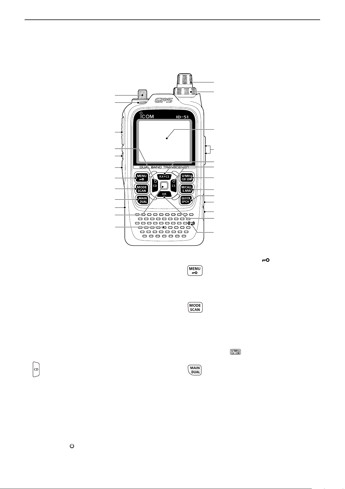
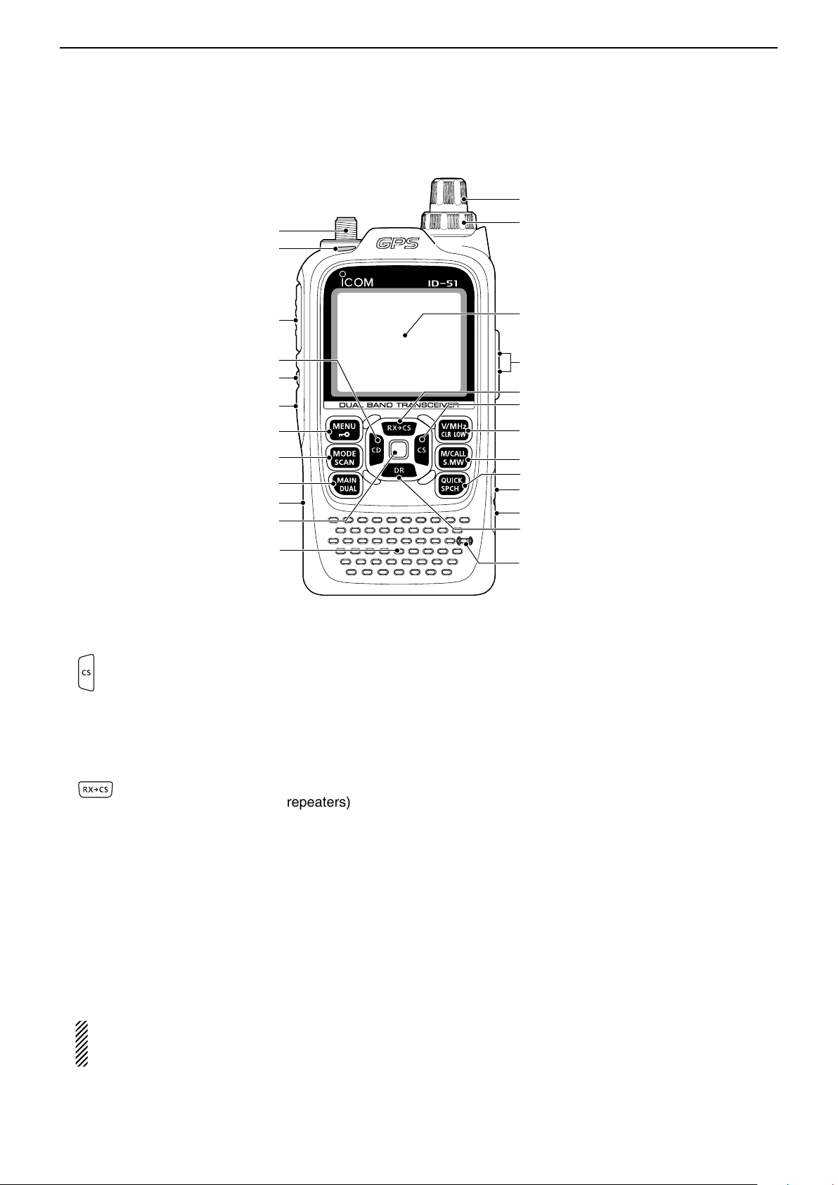
■ Front, top and side panels
q ANTENNA CONNECTOR (p. 1-2)
Connect the antenna here.
• An optional AD-92SMA adapter (p. 18-3) is available to
w TX/RX INDICATOR [TX/RX] (pp. 5-9, 5-10)
Lights green while receiving a signal or when the
squelch is open; lights red while transmitting.
e PTT SWITCH [PTT] (p. 5-10)
Hold down to transmit, release to receive.
For ID-51E only
Push briefly, then hold down to transmit a 1750 Hz
tone burst.
r CD (RX CALLSIGN DISPLAY)/D-PAD (LEFT) KEY
[CD]/D-pad()
t SQUELCH KEY [SQL]
y POWER KEY [ ]
Hold down for 1 second to turn the transceiver power
ON or OFF. (p. 5-2)
connect an antenna with a BNC connector.
➥ While in the DV mode, hold down for
1 second to open the received calls record.
(p. 9-5)
➥ While in the DR mode, or with the Menu
screen or Quick Menu screen opens, push
to select an upper tier menu. (p. 16-2)
Hold down to temporarily open the squelch and ➥
monitor the operating frequency.
While holding down this key, rotate ➥ [DIAL] to ad-
just the squelch level. (p. 5-6)
u MENU • LOCK KEY [MENU ]
➥ Push to enter or exit the Menu screen.
(p. 16-2)
➥ Hold down for 1 second to toggle the Key
Lock function ON or OFF. (p. 5-11)
i MODE • SCAN KEY [MODE•SCAN]
➥ Push to select the operating mode.
(p. 5-7)
• Selectable operating modes are AM, FM,
FM-N or DV.
➥ Hold down for 1 second to enter the scan
type selection mode. (pp. 13-5, 13-9)
• Push again to start the scan.
• Push
to stop the scan.
o MAIN • DUAL KEY [MAIN•DUAL]
➥ Push to toggle the main band between A
and B bands. (p. 5-3)
➥ Push and hold for 1 second to toggle the
dualwatch function ON or OFF. (p. 5-3)
!0 microSD CARD SLOT [micro SD]
Insert a microSD card of up to 32 GB SDHC.
!1 ENTER KEY [ENT]
While in the DR mode, or with the Menu screen or
Quick Menu screen open, push to open or set the
selected item or option. (p. 16-2)
3-2
Page 24
PANEL DESCRIPTION
q
w
r
u
i
o
!0
e
t
y
!1
!2
!3
!4
!5
!6
!7
!8
!9
Function
display (p. 3-5)
Internal
microphone
Speaker
@0
@1
@2
Previous view
3
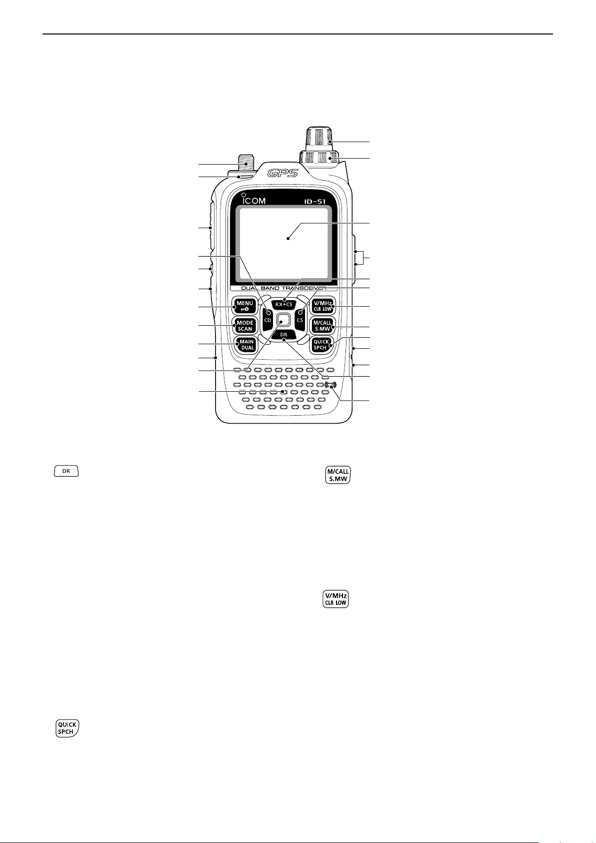
Front, top and side panels (Continued)
■
!2 DR (D-STAR REPEATER)/D-PAD (DOWN) KEY
[DR]/D-pad()
!3 EXTERNAL DC IN JACK [DC IN]
!4 DATA JACK [DATA]
Connects to a PC through the optional OPC-2218LU
data communication cable, for low-speed data communication in the DV mode or for cloning. The jack is
also used to connect an external GPS receiver.
See page 9-14 or 17-17 for more details.
!5 QUICK MENU • SPEECH KEY [QUICK SPCH]
➥ Hold down 1 second to enter the DR mode.
(p. 8-3)
➥ While in the DR mode, or with the Menu
screen or Quick Menu screen open, push
to move the value or option selector bar
down. (p. 16-2)
Connects to the supplied wall charger, BC-167SA/ ➥
SD/SV, to charge the attached battery pack. (p. 4-3)
Connect an external DC power supply through ➥
the optional CP-12L or CP-19R cigarette lighter
cable or OPC-254L DC power cable for external
DC operation. (p. 4-6)
➥ Push to enter or exit the Quick Menu
screen. (p. 5-4)
• The Quick Menu is used to quickly select various functions.
➥ Hold down for 1 second to audibly an-
nounce the displayed frequency, operating
mode or call sign. (p. 17-6)
!6 MEMORY/CALL • SELECT MEMORY WRITE KEY
[M/CALL•S.MW]
➥ In the VFO mode, push once to enter the
Memory selection mode, push again to enter the Call channel mode. (p. 8-3)
For ID-51A only
In the Call channel mode, push once to
enter the Weather channel mode.
➥ Hold down for 1 second to enter the Select
!7 VFO/MHz • CLEAR • OUTPUT POWER KEY
[VFO/MHz•CLR•LOW]
Memory Write mode. (p. 12-4)
➥ Push to select the VFO mode. (p. 5-8)
➥ While in the VFO mode, push to select
1 MHz and 10 MHz tuning steps. (p. 5-6)
➥ With the Menu screen or Quick Menu screen
open, push to return to the operating mode
before entering the menu screen. (p. 16-2)
➥ While in the Memory Name or Call Sign
3-3
Programming mode, push to delete the
character. (p. 12-11)
➥ While scanning, push to cancel a scan.
(pp. 13-5, 13-9)
➥ Hold down for 1 second to select the out-
put power. (p. 5-10)
• Select the transmit output power of High, Mid,
Low2, Low1 or S-low.
• While holding down this key, rotate [DIAL] to
select the desired output power.
Page 25
PANEL DESCRIPTION
q
w
r
u
i
o
!0
e
t
y
!1
!2
!3
!4
!5
!6
!7
!8
!9
Function
display (p. 3-5)
Internal
microphone
Speaker
@0
@1
@2
Previous view
3
Front, top and side panels (Continued) ■
!8 CS (CALL SIGN SELECT)/D-PAD (RIGHT) KEY
[CS]/D-pad()
!9 RXÚCS (RX CALL SIGN CAPTURE)/D-PAD (UP)
KEY [RXÚCS]/D-pad()
@0 EXTERNAL MICROPHONE/SPEAKER JACK
[MIC/SP]
Connect a cloning cable, optional speaker micro-
phone or headset, if desired.
See Section 18 for a list of available options.
Be sure to turn OFF the power before connecting
@1 VOLUME CONTROL [VOL]
Rotate to adjust the audio volume level. (p. 5-2)
➥ Hold down for 1 second to enter the oper-
ating call sign select mode.
➥ While in the DR mode, or with the Menu
screen or Quick Menu screen open, push
to select a lower tier menu. (p. 16-2)
➥ Hold down for 1 second to set the received
call signs (station and repeaters) as the
operating call sign.
• While holding down this key, rotate [DIAL] to
select another call sign in the RX history.
➥ While in the DR mode, or with the Menu
screen or Quick Menu screen open, push
to move the value or option selector bar up.
(p. 16-2)
or disconnecting optional equipment to or from
the [MIC/SP] jack.
@2 CONTROL DIAL [DIAL]
Rotate to select the operating frequency. (p. 5-6) ➥
While in the Memory mode, rotate to select a ➥
memory channel. (p. 12-3)
While scanning, rotate to change the scanning ➥
direction. (p. 13-3)
Hold down [SQL], and rotate to select the squelch ➥
level. (p. 5-6)
While in the DR mode, or with the Menu screen ➥
or Quick Menu screen open, rotate to select a desired option or value.
3-4
Page 26
PANEL DESCRIPTION
点滅
Previous view
3
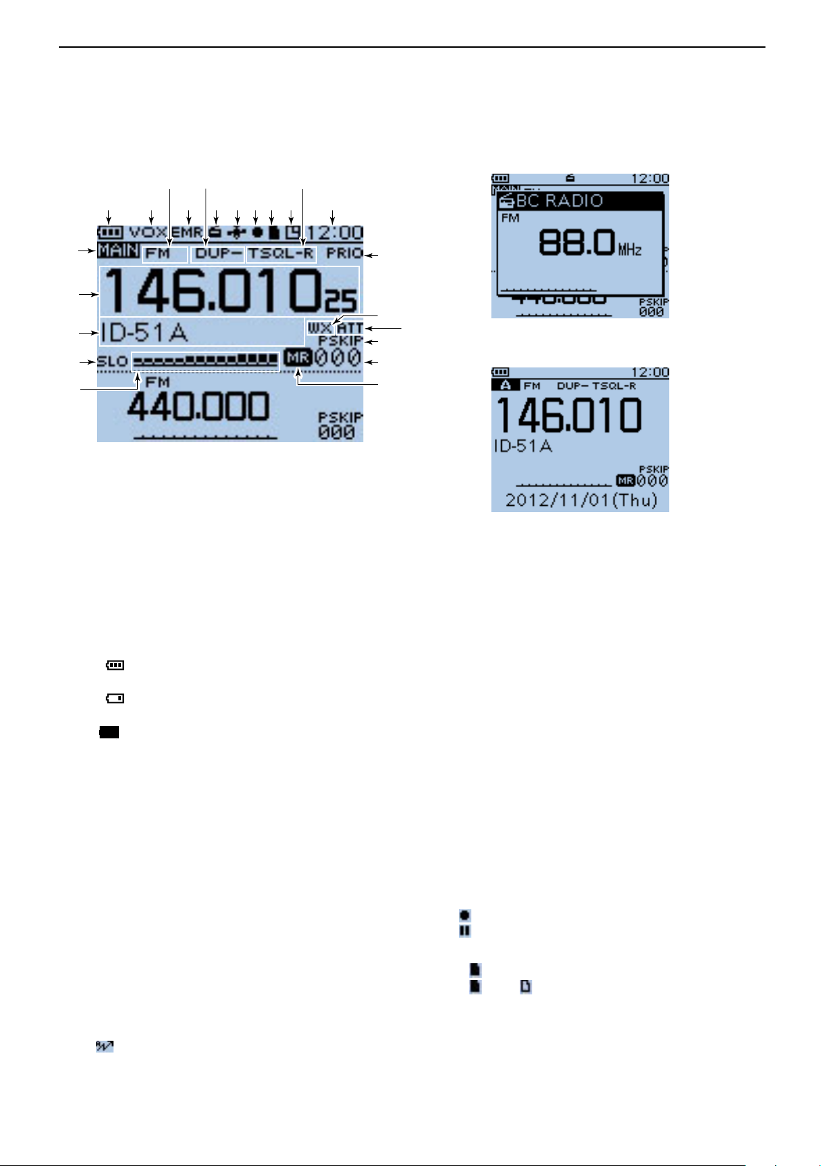
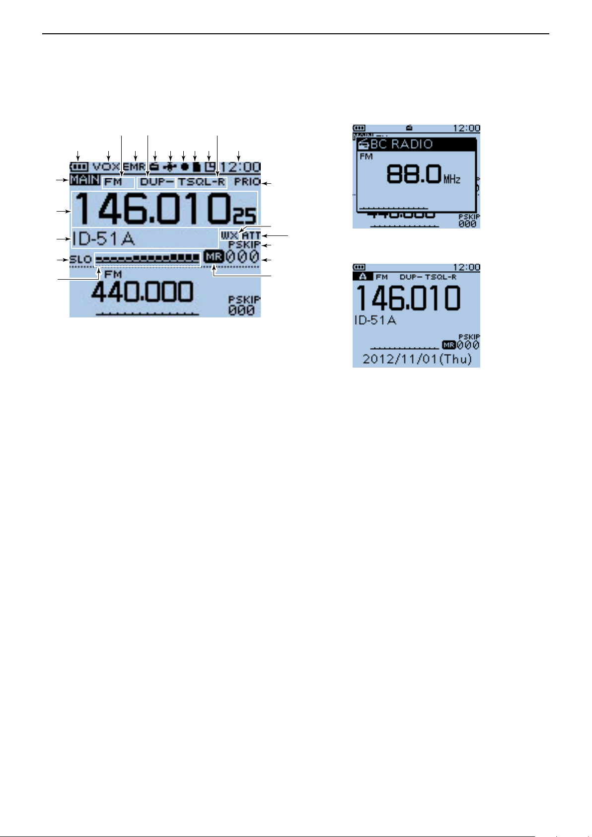
■ Function display
@3
@2
@1
@0
!9
q
te
!1
w r y u io !0 !2
Dual band display
!3
!4
!6
!7
!8
!5
BC Radio setting pop-up
window (Tuning mode)
Single band display
q BATTERY ICON
Shows the capacity of the attached battery pack ➥
in four levels. (p. 4-2)
•“ ” (battery icon) appears when the battery
pack is attached.
•“ ” appears when the battery pack must be
charged.
“ ➥
” appears when the optional battery case is
attached. (p. 4-4)
w VOX ICON (p. 18-6)
Appears when the optional headset is connected
with the OPC-2006LS p l u g a d a p t e r c a b l e , and the
VOX function is ON.
e OPERATING MODE ICONS (p. 5-7)
Shows the selected operating mode.
•DV,AM,FMandFM-Nareselectable.
•“DV-G”or“DV-A”appearswhenGPSorGPS-Atransmis-
sion is selected in the DV mode. (p. 10-16)
r EMR/BK/Packet Loss/Auto Reply ICON
“EMR”appearswhentheEnhancedMonitorRe- ➥
quest(EMR)modeisselected.(p.9-8)
“BK”appearswhentheBreak-in(BK)modeisse- ➥
lected.(p.9-7)
“L” appears when Packet Loss has occurred. ➥
(p.9-14)
“ ➥ ” appears when the Automatic Reply function
isselected.(p.9-11)
t DUPLEX ICON (p. 15-5)
“DUP+”appearswhenplusduplexisselected,and
“DUP–”appearswhenminusduplexisselected.
y BC RADIO ICON (p. 6-2)
AppearswhentheBCradioisON.
u GPS ICON
AppearswhileGPSfunctionisinuse.(p.10-2) ➥
StaysONwhentheGPSreceiverisactivatedand
valid position data is received.
Blinks when invalid position data is being re-
ceived.
•GPSiconscanbeturnedOFFintheMenuscreen.
(p. 16-33)
“ ➥ S”blinksinstead of the GPSicon,whenthe
GPSalarmbeeps.(p.10-14)
i RECORD ICON (p. 11-2)
Appears while recording.
•“ ” appears while the transceiver is recording.
•“
” appears while the recording is paused.
o microSD ICON (Section 2)
“ ➥ ” appears when a microSD card is inserted.
“ ➥ ”and“ ” alternately blinks while accessing the
microSD card.
!0AUTO POWER OFF ICON (p. 16-83)
AppearswhentheAutopowerOFFfunctionisON.
3-5
Page 27

PANEL DESCRIPTION
Previous view
3
Function display (Continued) ■
@3
@2
@1
@0
!9
q
te
!1
w r y u io !0 !2
Dual band display
!3
!4
!6
!7
!8
!5
BC Radio setting pop-up
window (Tuning mode)
Single band display
!1 TONE ICONS
•WhileoperatinginFM/FM-Nmode:
(pp. 17-13, 17-15)
“ TONE” appears while the Repeater Tone Encod- ➥
er is ON.
“ TSQL” appears while the Tone squelch function ➥
is ON.
“ TSQL-R” appears while the Reverse Tone ➥
squelch function is ON.
“ DTCS” appears while the DTCS squelch function ➥
is ON.
“ DTCS-R” appears while the reverse DTCS ➥
squelch function is ON.
“ ➥ S” appears with the “TSQL” or “DTCS” icon
while the Pocket Beep function (with CTCSS or
DTCS) is ON.
•WhileoperatinginDVmode: (pp. 9-19, 9-20)
“ DSQL” appears while the Digital Call Sign squelch ➥
function is ON.
“ CSQL” appears while the Digital Code squelch ➥
function is ON.
“ ➥ S” appears with the “DSQL” or “CSQL” icon
while the Pocket Beep function (with Digital Call
Sign or Digital Code squelch) is ON.
!2 CLOCK DISPLAY (p. 16-82)
Displays the current time.
!3 PRIORITY WATCH ICON (p. 14-5)
Appears when Priority Watch is in use.
!4 WEATHER ALERT ICON (p. 5-15)
Appears when the Weather alert function is ON.
!5 ATTENUATOR ICON (p. 5-11)
Appears when the attenuator is ON in the AIR band.
!6 SKIP ICON (pp. 13-7, 13-8)
“ SKIP” appears when the selected memory chan- ➥
nel is set as a skip channel.
“ PSKIP” appears when the displayed frequency is ➥
set as a skip frequency in the Memory mode.
“ PSKIP” appears while the Frequency Skip Scan ➥
function is ON in the VFO mode.
!7 MEMORY CHANNEL NUMBER
Displays the selected memory channel or bank ➥
number. (p. 12-3)
“C0” to “C3” appears when the Call channel is se- ➥
lected. (p. 12-3)
!8 MEMORY ICON (p. 12-3)
Appears when the Memory mode is selected.
3-6
Page 28
PANEL DESCRIPTION
Previous view
3
Function display (Continued) ■
@3
@2
@1
@0
!9
q
te
!1
w r y u io !0 !2
Dual band display
!3
!4
!6
!7
!8
!5
BC Radio setting pop-up
window (Tuning mode)
Single band display
!9 S/RF METER
Shows the relative signal strength of the receive ➥
signal. (p. 5-9)
Shows the output power level of the transmit signal. ➥
(p. 5-10)
@0 POWER ICONS (p. 5-10)
“ SLO” appears when S-low power is selected. ➥
“ LO1” appears when low 1 power is selected. ➥
“ LO2” appears when low 2 power is selected. ➥
“ MID” appears when mid power is selected. ➥
No icon appears when high power is selected. ➥
@1 MEMORY NAME DISPLAY (p. 12-12)
While in the Memory mode, the programmed mem-
ory or memory bank name is displayed.
@2 FREQUENCY READOUT
Displays a variety of information, such as the operat-
ing frequency, menu contents and so on.
• The decimal point blinks during a scan.
@3 MAIN BAND ICON (p. 5-3)
Shows the the selected band (A or B) is the Main
band.
3-7
Page 29

Section 4
Previous view
BATTERY CHARGING
Battery information ■ .............................................. 4-2
Battery life D ....................................................... 4-2
Battery icon D .................................................... 4-2
Charging through the [DC IN] jack ■ ....................... 4-3
Battery icon D ..................................................... 4-3
Charging note D .................................................. 4-3
Optional battery case ■ .......................................... 4-4
Battery life D ....................................................... 4-4
About the battery replacement D ........................ 4-4
Charging with the optional desktop charger ■ ........ 4-5
Charging note D .................................................. 4-5
External DC power operation ■ .............................. 4-6
Operating note D ................................................. 4-6
4-1
Page 30
BATTERY CHARGING
Previous view
4
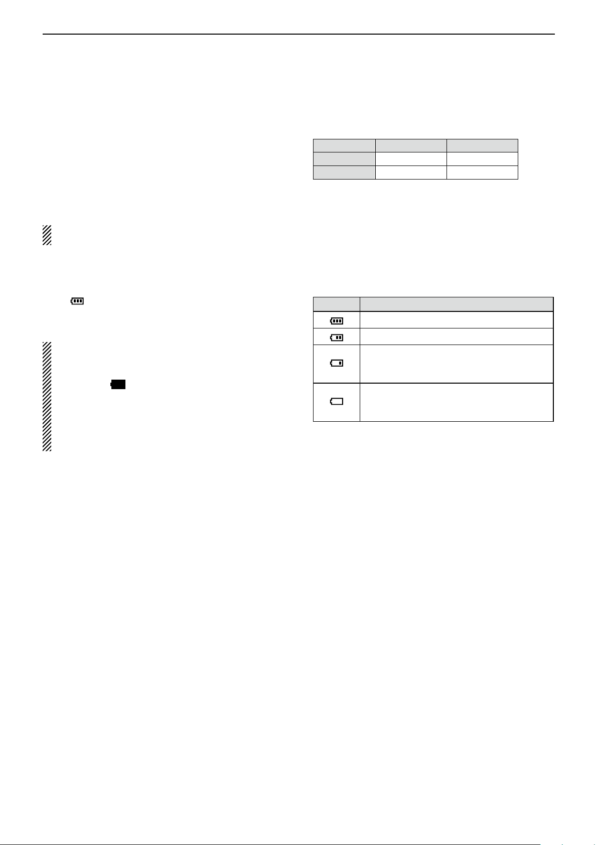
■ Battery information
D Battery life
The approximate battery life (operating time) as shown
to the right is calculated under the following assumptions:
• Power save setting: Auto (Short)
• Duty cycle: TX : RX : Stand-by = 1 : 1: 8 (based on
operating style)
See page 4-4 for the optional BP-273 b at t e r y c a s e
battery life.
Battery icon D
The “ ” battery icon appears when the BP-271 or
BP-272 Li-ion battery pack is attached to the transceiver.
• When the BP-273 battery case is attached to the
transceiver, the battery icon cannot display the battery capacity of the alkaline batteries. The battery
icon stays “点滅,” and it does not reflect with the true
battery capacity.
• Without disconnecting the battery charger or external DC power, the battery icon does not appear
when turning power ON after charging is completed.
Battery pack FM mode
BP-271 Approx. 4.5 hrs. Approx. 4.5 hrs.
BP-272 Approx. 8 hrs. Approx. 7 hrs.
Icon
The battery has sufficient capacity.
The battery is exhausted a little.
The battery is nearing exhaustion. Charg-
ing is necessary. (The transceiver can be
operated for a short time.)
The battery is almost exhaustion. Charging is necessary. (The transceiver quickly
becomes impossible to operate.)
Battery condition
DV mode
4-2
Page 31

BATTERY CHARGING
• BC-167S
• CP-12L (Optional)
• OPC-254L (Optional)
to AC outlet
to cigarette lighter
socket (12 V DC)
to 12 V DC
(power supply)
White: +
Black: _
Transceiver
to
[DC IN]
Tu rn power OFF
while charging
the battery pack.
The BC-167SA,
BC-167SD and
BC-167SV have
different shapes.
BP-271
• CP-19R (Optional)
Previous view
4
■ Charging through the [DC IN] jack
Prior to using the transceiver for the first time, the battery pack must be fully charged for optimum life and
operation.
BE SURE to turn OFF the power while charging. Otherwise the attached battery pack cannot be charged. (see
page 4-6 for details)
Battery icon D
While charging, the charging icon “ ” sequentially
shows eleven level steps along with the word “Charging...”.
The icon disappears when the battery pack is completely charged.
While charging
D Charging note
• When using the supplied BC-167S battery charger, be
sure to turn OFF the transceiver power. Otherwise the
battery pack will not be charged completely, or it will
take much longer to charge.
• When using an optional CP-12L, CP-19R or OPC-
254L, the battery pack can be charged at power ON.
But by default, the battery pack cannot be charged at
power ON, so you should turn OFF the power before
charging. (p. 16-71)
• Even if rechargeable batteries, Ni-Cd or Ni-MH, are
installed in the optional BP-273 battery case, they
cannot be charged.
• The battery pack can be charged approximately 500
times.
• Charging period: BP-271 approximately 3.0 hours
BP-272 approximately 4.5 hours
BE SURE to attach the battery pack
before connecting the DC cable.
4-3
Page 32

BATTERY CHARGING
Previous view
4
■ Optional battery case
When using the BP-273 b at t e r y c a s e , install three AA
(LR6) size alkaline batteries, as described below.
Remove the battery case if it is attached. (p. 1-2) q
Install three AA (LR6) size alkaline batteries. w
• Install only alkaline batteries.
• Be sure to observe the correct polarity.
Attach the battery case. (p. 1-2) e
A built-in step-up converter in the BP-273 increases
the voltage to 5.5 V DC.
Approximately 100 mW of output power is possible
with the BP-273 operation. Also, the transmit output
power selection is disabled.
CAUTION:
• When installing batteries, make sure they are all
the same brand, type and capacity. Also, do not mix
new and old batteries together.
• Keep the battery terminals clean. It’s a good idea to
occasionally clean them.
• Never incinerate used battery cells since the internal battery gas may cause them to rupture.
• Never expose a detached battery case to water.
If the battery case gets wet, be sure to wipe it dry
before using it.
• Never use batteries whose insulated covering is
damaged.
• Remove the alkaline batteries when battery case is
not used. Otherwise the installed alkaline batteries
will exhausted due to built-in step-up converter.
Battery life D
The approximate battery life (operating time) as shown
below is calculated under the following assumptions;
• Power save setting: Auto (Short)
• Duty cycle: TX : RX : Stand-by = 1 : 1: 8 (based on
operating style)
FM mode
Approx. 7.5 hrs. Approx. 7 hrs.
NOTE:
• The battery life may differ, depending on the operating style or the installed alkaline batteries.
• The batteries may seem to have low capacity when
used in low temperatures, such as –10°C (+14°F)
or below. Keep the batteries warm in this case.
DV mode
D About the battery replacement
When the alkaline batteries are almost exhausted,
“LOW BATTERY” is displayed and the battery icon
starts to blink. After 10 seconds, the transceiver power
is automatically turned OFF.
In that case, replace all batteries with new alkaline batteries.
When the BP-273 battery case is attached to the
transceiver, the battery icon cannot display the battery capacity of the alkaline batteries. The battery
icon stays “点滅,” and it does not reflect with the true
battery capacity.
4-4
Page 33
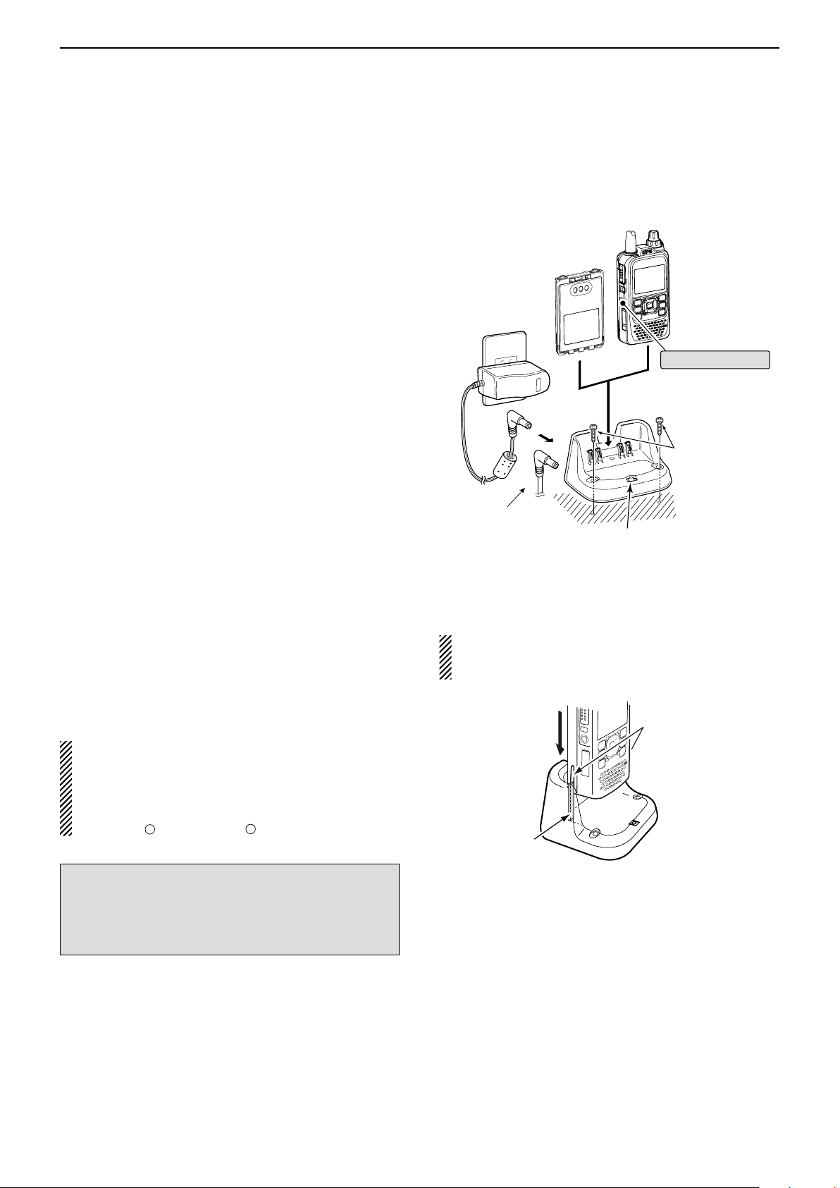
BATTERY CHARGING
Guide rail
Tabs
–
Transceiver
(with battery pack)
Tu rn OFF the power
Battery pack
BC-202 (optional)
Desktop charger
Charging indicator
• Lights orange : While charging
• Lights green : Charging is completed
• Blinks orange : A charging error has
occured
AC Adapter
(A different type, or
no AC adapter is
supplied, depending
on the version.)
Screws*
(Self tapping screws:
3.5 × at least 30 mm)
*Purchase separately.
Using screws is
recommended to
secure the charger.
The optional OPC-515L
(for DC power source)
or CP-23L (for 12 V
cigarette lighter socket)
can be used instead of
the AC adapter.
Previous view
4
■ Charging with the optional desktop charger
The optional BC-202 rapidly charges of the BP-271
and BP-272 Li-ion battery packs.
D Charging note
• Be sure to turn OFF the transceiver power.
When the transceiver power cannot be turned OFF,
detach the battery pack from the transceiver. Then
charge the battery pack by itself, or charge the battery using regular charging. Otherwise the battery
pack will not be charged (the charging indicator on
the BC-202 blinks orange about 10 second after the
battery pack is installed in BC-202).
• The BC-202 desktop charger can only charge BP-
271 or BP-272 Li-ion battery packs. Other types of
rechargeable batteries, Ni-Cd or Ni-MH cannot be
charged.
• If the charging indicator blinks orange, there may be
a problem with the battery pack or charger. If this occurs, try charging the battery pack alone, without the
transceiver, or try using the standard (non-rapid) charger. Contact your dealer if you have problems charging a new battery pack.
• NEVER place the transceiver with the battery pack
to the desktop charger when the transceiver is connected to the DC power supply. This may cause the
charger’s malfunction and the charging indicator of
the charger lights red. In that case, disconnect the AC
adapter from the charger, and then reconnect the AC
adapter to the charger.
• The optional CP-23L and OPC-515L can be used
instead of the supplied AC adapter. Connect one of
these to the [DC 12-16V] jack.
• Charging time: BP-271 approximately 2.0 hours
BP-272 approximately 3.5 hours
IMPORTANT: Battery charging caution
Ensure the guide rails on the battery pack are correctly aligned with the tabs inside the charger.
CAUTION: When using the OPC-515L DC power
cable
NEVER connect the OPC-515L to a power source
using reverse polarity. This will ruin the battery charger.
White line: + Black line:
NOTE: If the charging indicator blinks orange for 10
seconds or more with the battery pack installed in the
transceiver, try charging the BP-271 alone. You can
also try regular charging the BP-271 attached to the
transceiver.
4-5
Page 34

BATTERY CHARGING
D-pad
(�)
(Ent)
BP-271
• CP-12L (Optional)
• CP-19R (Optional)
• OPC-254L (Optional)
to a cigarette lighter
socket (12 V DC)
to a 12 V DC
(power supply)
White: +
Black: _
to
[DC IN]
Transceiver
Previous view
4
■ External DC power operation
An optional CP-12L or CP-19R cigarette lighter cable,
for a 12 V cigarette lighter socket, or an OPC-254L external DC power cable can be used for external power.
The attached battery pack will not be charged while operating the transceiver if “Charging (Power ON)” is set
to the factory default setting. If the setting is set to ON in
the MENU screen, the battery pack can be charged.
• The external DC power supply voltage must be between
10–16 V, and the current capacity must be more than 2.5 A
to charge the battery pack when operating.
Connect the DC cable as shown to the right. q
Push [MENU] w to enter the Menu screen.
Push D-pad( e ) to select the root item (Function),
and then push D-pad(Ent) to go to the next level.
( MENU > Function > Charging (Power ON))
Refer to the menu sequence shown directly above r
and push D-pad() to select, and then push Dpad(Ent) to enter, one or more times until the last
screen is displayed.
Push D-pad( t ) to select “ON.”
• OFF : The transceiver cannot be charged when the power
• ON : The transceiver can be charged even if the power
When the transceiver power is ON, the battery icon
sequentially shows “ ,” “ ,” “ ” and “ ”
while charging, and the icon disappears when the
battery pack is completely charged.
• The power supply voltage must be between 10.0–
16.0 V DC.
NEVER CONNECT OVER 16 V DC directly into the [DC
IN] jack of the transceiver.
• BE SURE to use a CP-12L, CP-19R or OPC-254L
when connecting a regulated 12 V DC power supply.
Use an external DC-DC converter to connect the transceiv-
er through an optional CP-12L, CP-19R or OPC-254L to a
24
• The voltage of the external power supply must be
between 10–16 V DC when using either CP-12L, CP19R or OPC-254L, otherwise, use the battery pack.
• Disconnect the power cables from the transceiver
when not using it. Otherwise, the vehicle battery will
become exhausted.
is ON.
is ON.
Operating note D
V DC power source.
BE SURE to attach the battery pack
before connecting the DC cable.
• “Charging (Power ON)” setting screen
NOTE: Up to 5 W (approximately) of maximum output power is possible when using external DC power.
However, when the supply voltage exceeds 14 V, the
built-in protection circuit activates to reduce the transmit output power to approximately 2.5 W.
• The power save function is automatically deactivated
when using an external DC power source.
• Be sure to observe the correct polarity of the OPC-
254L supply connection.
• When external power is used, the power save func-
tion is automatically turned OFF.
• ID-51A/E’s charging circuit may generate certain
spurious signals; the S-meter appears, or noise may
be heard.
When you operate the transceiver while charging, and
if you cannot receive signals correctly, set “Charging
(Power ON)” in the MENU screen to OFF.
4-6
Page 35

Section 5
Previous view
BASIC OPERATION
Power ON ■ ............................................................ 5-2
Setting audio volume ■ ........................................... 5-2
MAIN band selection ■ ........................................... 5-3
Selecting the operating band ■ ............................... 5-4
Selecting a tuning step ■ ........................................ 5-5
Tuning step selection D ....................................... 5-5
Setting a frequency ■ ............................................. 5-6
Setting the squelch level ■ ...................................... 5-6
Selecting the operating mode ■ .............................. 5-7
Monitor function ■ ................................................... 5-7
Selecting the Mode ■ .............................................. 5-8
VFO mode D ....................................................... 5-8
D
Memory/Call channel/Weather channel* mode
DR (D-STAR Repeater) mode D ......................... 5-8
Receiving ■ ............................................................. 5-9
Transmitting ■ ....................................................... 5-10
About transmit power levels D ........................... 5-10
Key Lock function ■ .............................................. 5-11
ATT (AIR) function ■ ............................................. 5-11
Band Scope function ■ ......................................... 5-12
Sweep operation D ........................................... 5-12
Dualwatch operation ■ .......................................... 5-13
MAIN band selection D ..................................... 5-13
Setting the volume for Dualwatch D .................. 5-14
Weather channel operation ■
(U.S.A. version transceivers only) ...................... 5-15
Weather channel selection D ............................ 5-15
Weather alert function D ................................... 5-15
.. 5-8
5-1
Page 36
BASIC OPERATION
Previous view
5
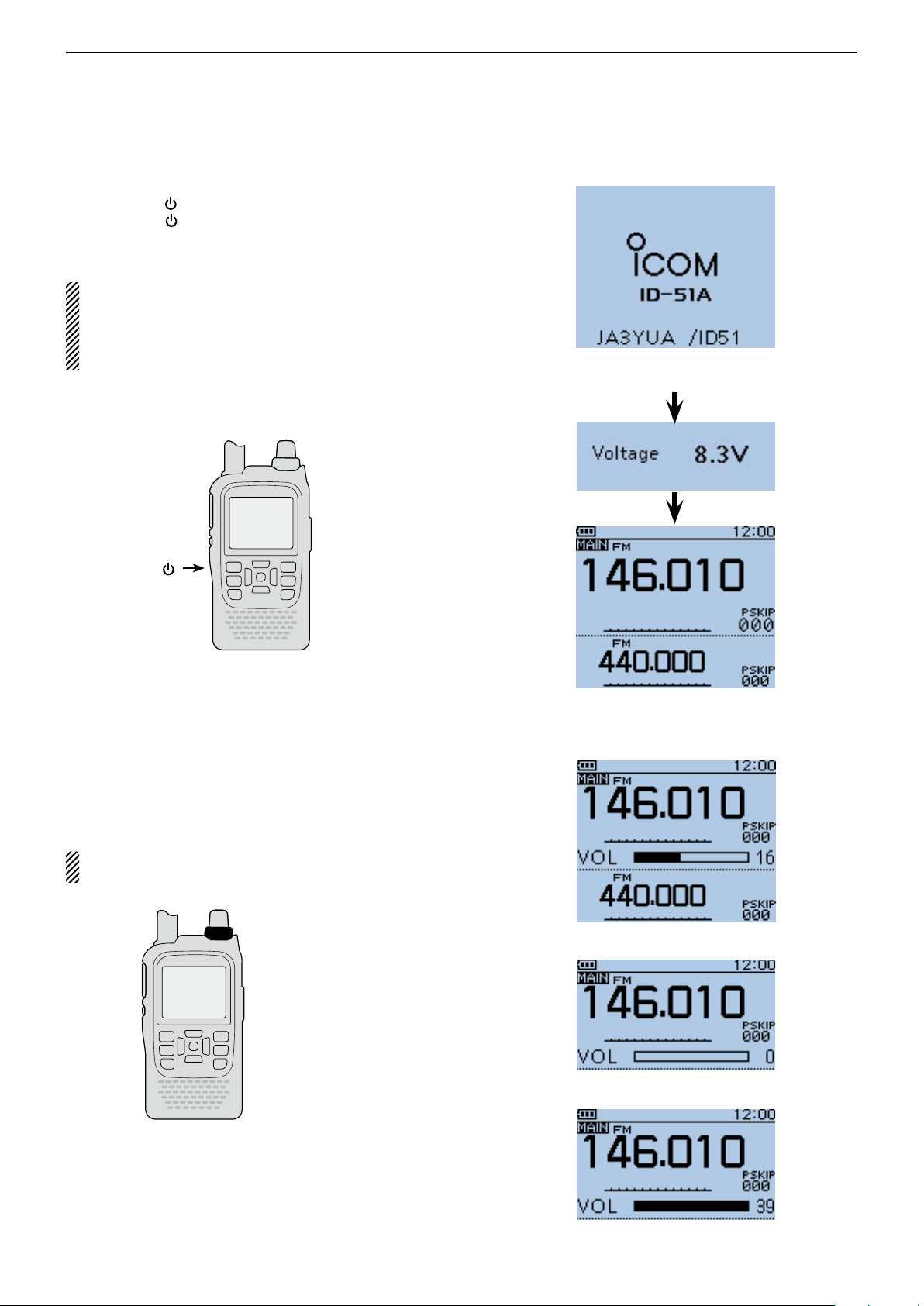
■ Power ON
Hold down [ ➥ ] for 1 second to turn ON power.
•Holddown[ ] for 1 second to turn OFF power.
•Aftertheopeningmessageandpowersourcevoltageare
displayed,theoperatingfrequencyappears.
The opening message and power source voltage
displayoptionscanbeturnedONorOFFintheDisplaymenu.
MENU>Display>Opening Message (p. 16-76)
MENU >
Display
> Voltage (Power ON) (p. 16-76)
When “JA3YUA/ID51” is set as
yourowncallsignandnote.
[ ]
■ Setting audio volume
Rotate[VOL]toadjusttheaudiolevel. ➥
•Ifthesquelch is closed, hold down[SQL]whilesetting
theaudiolevel.
•Thedisplayshowsthevolumelevelwhileadjusting.
ThebeeplevelisadjustedintheSoundsmenu.
MENU > Sounds > Beep Level (p. 16-79)
[VOL]
Volumeleveldisplay
Noaudio
Maximumaudio
5-2
Page 37
BASIC OPERATION
Previous view
5
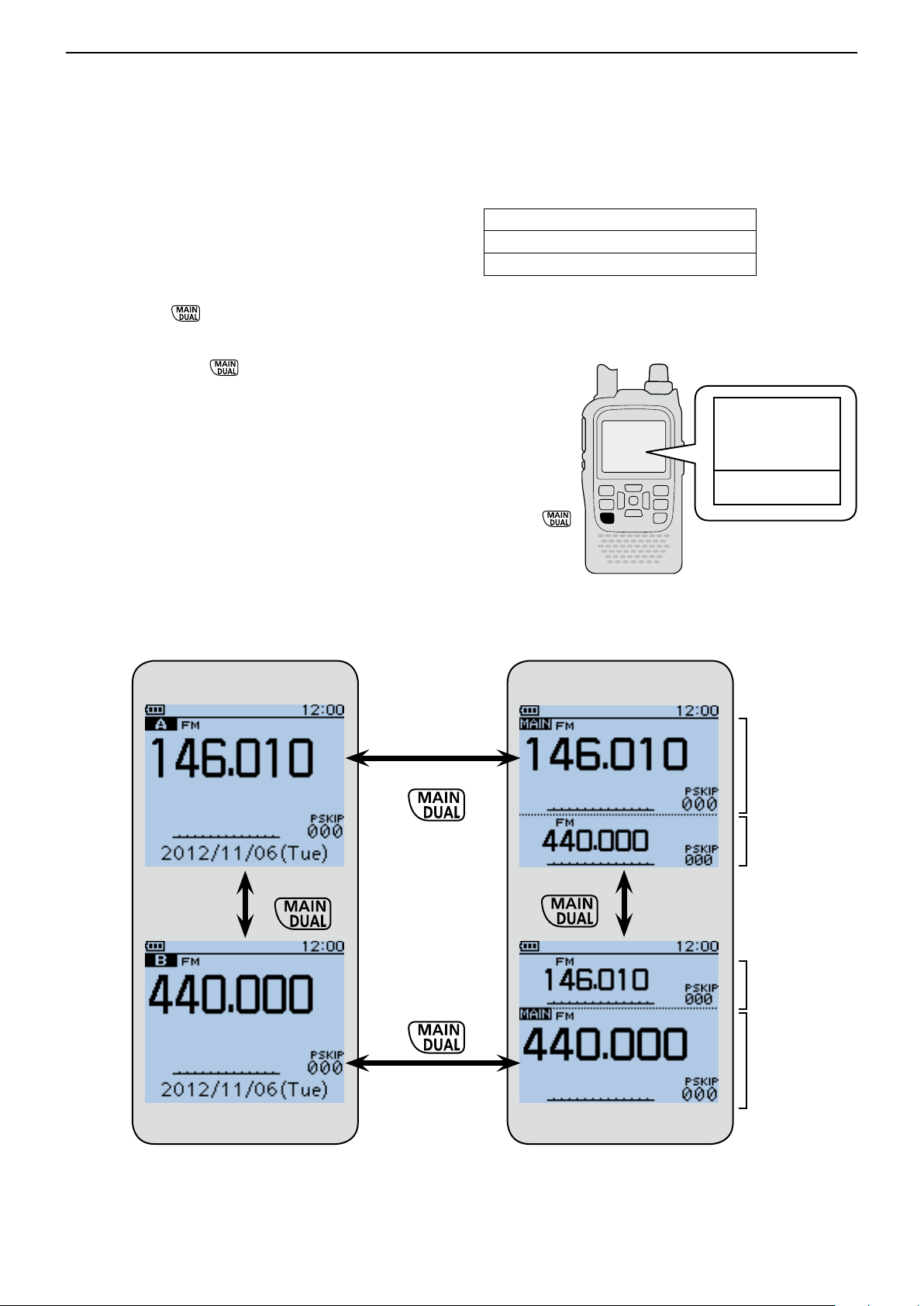
■ MAIN band selection
The ID-51A/E has two independent operating bands; A
band and B band.
The transceiver can monitor two frequencies simultaneously on A band and B band. This is called Dualwatch
operation. (p. 5-13)
Push [MAIN] ➥ to toggle the MAIN band between
A and B band.
• “MAIN” appears on the MAIN band.
Hold down [DUAL] ➥ for 1 second to turn the dual-
watch operation ON or OFF.
• During Dualwatch operation, the display shows the A
band in the upper half and the B band in the lower half.
• When Dualwatch operation is OFF, the display shows
only the MAIN band.
Single band operation
Frequency range on the A/B bands:
108.000 MHz to 174.000 MHz
137.000 MHz to 174.000 MHz
380.000 MHz to 479.000 MHz
• Some frequency ranges are blocked for the U.S.A. and Aus-
tralian version by regulation.
Upper: A band
Lower: B band
Dualwatch operation
Selecting A band
Selecting B band
Push
Hold down
Hold down
Selecting upper half as
MAIN band
MAIN band
(A band)
SUB band
(B band)
Push
SUB band
(A band)
MAIN band
(B band)
Selecting lower half as
MAIN band
5-3
Page 38
BASIC OPERATION
D-pad
(�)
(Ent)
Previous view
5
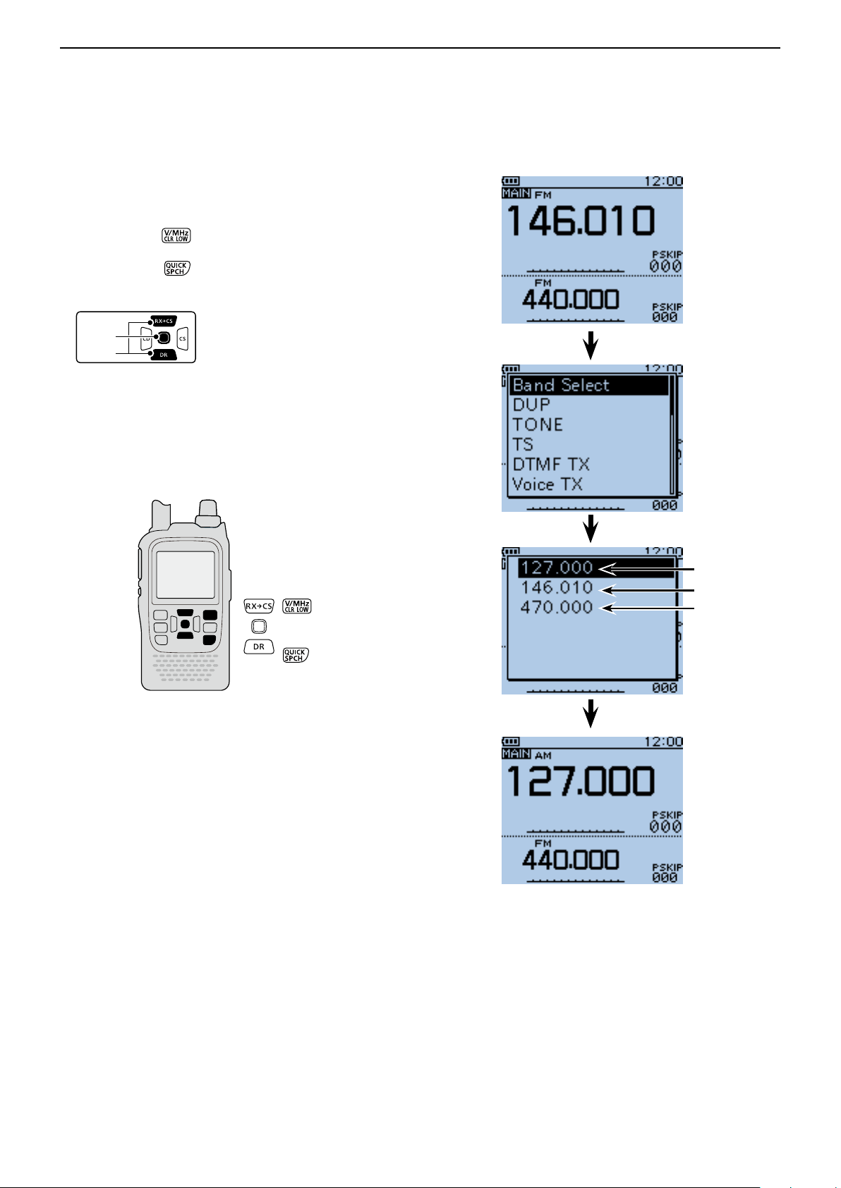
■ Selecting the operating band
The transceiver can receive the AIR, 144 MHz or 430
MHz bands.
q Push [V/MHz] to select the VFO mode, if neces-
sary.
Push [QUICK] w to open the Quick Menu screen.
Push D-pad( e ) to select “Band Select,” and then
push D-pad(Ent).
Push D-pad( r ) to select the desired frequency
band.
• Available frequency bands are differ, depending on version. See the specifications for details. (p. 19-2)
Push D-pad(Ent) to set and exit the Quick Menu t
screen.
AIR band
144 MHz band
430 MHz band
5-4
Page 39
BASIC OPERATION
D-pad
(�)
(Ent)
Previous view
5
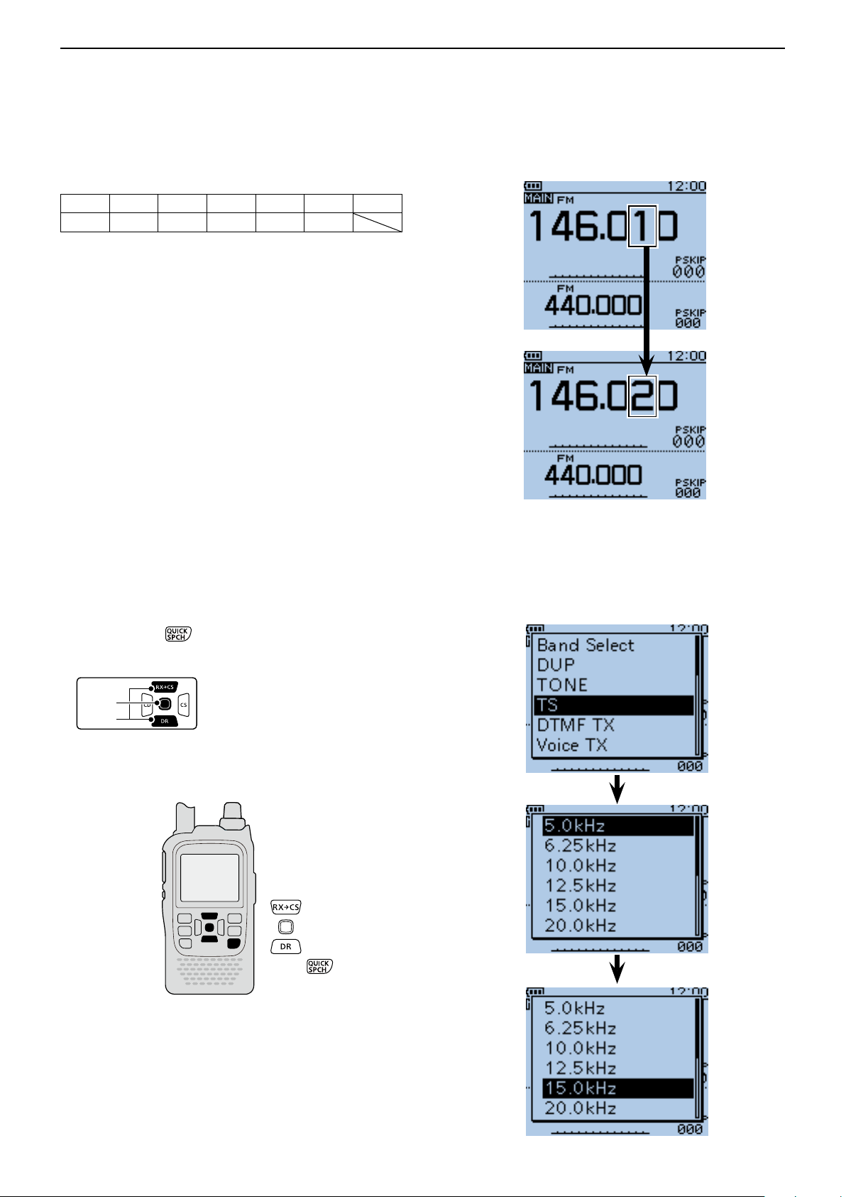
■ Selecting a tuning step
The following tuning steps are selectable. (kHz)
5.0 6.25 8.33* 10.0 12.5 15.0 20.0
25.0 30.0 50.0 100.0 125.0 200.0
*Appears only when the AIR band is selected.
D Tuning step selection
Push [QUICK] q to open the Quick Menu screen.
Push D-pad( w ) to select “TS,” and then push D-
pad(Ent).
Push D-pad( e ) to select the desired tuning step.
Push D-pad(Ent) to save the setting and exit the r
Quick Menu screen.
When 10 kHz tuning steps
is selected, the frequency
changes in the 10 kHz steps.
5-5
Page 40
BASIC OPERATION
Previous view
5
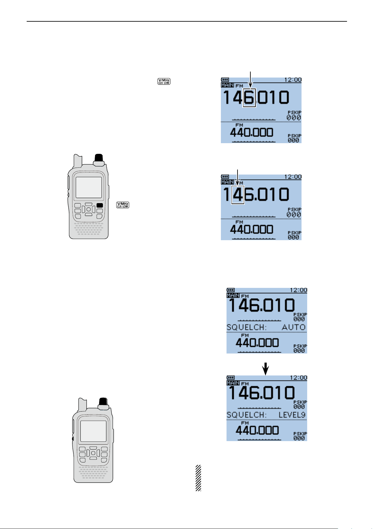
■ Setting a frequency
q When VFO mode is selected, push [V/MHz] to
select the 1 MHz or 10 MHz Quick Tuning function
step, or turn it OFF.
• When the 1 MHz step is selected, the frequency changes in
1 MHz steps.
• When the 10 MHz step is selected, the frequency changes
in 10 MHz steps.
Rotate [DIAL] to select the desired frequency. w
• The frequency changes according to the selected tuning
steps. See page 5-5 for details.
[DIAL]
Blinks
When the frequency changes
in 1 MHz steps.
Blinks
When the frequency changes
in 10 MHz steps.
■ Setting the squelch level
The squelch function mutes the noise or received audio signal, depending on the signal strength and the
squelch control setting.
While holding down [SQL], rotate [DIAL] to select the ➥
squelch level.
• While holding down [SQL], rotate [DIAL] one click to display the squelch level.
• “ LEVEL1” is loose squelch (for weak signals) and “LEV-
EL9” is tight squelch (for strong signals).
• “ AUTO” shows automatic level adjustment by a noise
pulse counting system.
• “OPEN” shows a continuously open setting. (This option
is not selectable in the DV mode.)
[DIAL]
[SQL]
Automatic squelch
Maximum level
NOTE: The independent squelch level can be set to
the A band and B band.
The squelch level setting can be done only for the
MAIN band.
5-6
Page 41

BASIC OPERATION
Previous view
5
■ Selecting the operating mode
Operating modes are determined by the modulation of
the radio signals. The transceiver has a total of four operating modes; AM, FM, FM-N and DV.
Push [MODE] ➥ one or more times to select a de-
sired operating mode.
•TheAMmodecanbeusedforonlytheAIRband(108.000
MHzto136.995MHz).
•WhentheGPSTXModeisset,“DV-G”or“DV-A”appears
insteadof“DV.”(p.10-16)
AM mode selected
FM mode selected
FM-N mode selected
■ Monitor function
This function is used to listen to weak signals without
disturbing the squelch setting, or having to open the
squelch manually even when mute functions such as
the tone squelch are in use.
Hold down [SQL] to monitor the operating frequen- ➥
cy.
•The1stsegmentoftheS-meterblinks.
The [SQL] key can be set to ‘sticky’ operation in
Function menu.
MENU > Function > Monitor(p.16-66)
DV mode selected
The first segment
blinks
[SQL]
5-7
Page 42
BASIC OPERATION
Previous view
5
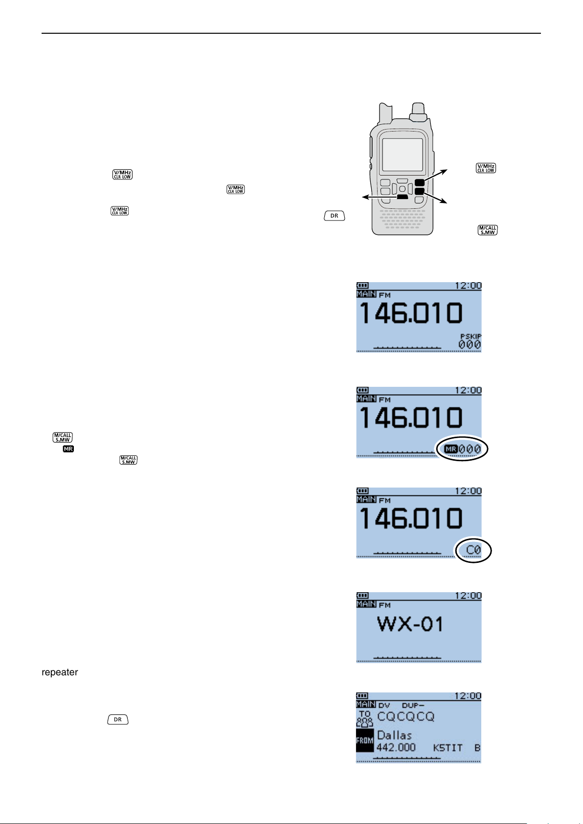
■ Selecting the Mode
D VFO mode
The VFO mode is used to set the desired frequency.
Push [V/MHz] q to select the VFO mode.
• When VFO mode is selected, push [V/MHz] then rotate [DIAL] to change the frequency in 1 MHz steps. Or
push [V/MHz]
Rotate [DIAL] to set the operating frequency. w
again for 10 MHz steps.
DR mode
Hold down
to select
VFO mode
Push
Memory mode
Call channel mode
WX channel* mode
Push
to alternately select
to select
D Memory/Call channel/
Weather channel* mode
• Memory mode
Memory mode is used for operation on Memory channels, which store programmed frequencies.
• Call channel mode
Call channels are used for quick recall of most-often
used frequencies.
• Weather channel mode*
Weather channels are used for monitoring weather
channels from the NOAA (National Oceanographic and
Atmospheric Administration) broadcasts.
When the VFO mode is selected, push [M/CALL] q
to select the memory mode.
• “
” and the selected Memory channel number appear.
Push [M/CALL] w again to select the Call channel
mode, and then push again to select the Weather
channel mode.
• The Memory mode, Call channel mode or Weather channel mode* are alternately selected.
• While in the Call channel mode, the selected Call channel number (“C0” to “C3”) appears.
• While in the Weather channel mode*, the selected weather channel number (“WX-01” to “WX-10”) appears.
Rotate [DIAL] to select a desired channel. e
• Only programmed Memory channels can be selected.
• See p. 12-4 for memory programming details.
• VFO mode
• Memory mode
Appears
• Call channel mode
Appears
• Weather channel mode*
*Appears in only the U.S.A. version transceivers.
D DR (D-STAR Repeater) mode
The DR (D-STAR Repeater) mode is used for D-STAR
repeater operation. In this mode, you can easily select
the preprogrammed repeaters and UR call signs by rotating [DIAL].
Hold down q for 1 second to select the DR
mode.
Rotate [DIAL] to select a desired access repeater. w
• DR mode
5-8
Page 43
BASIC OPERATION
D-pad
(�)
(Ent)
Previous view
5
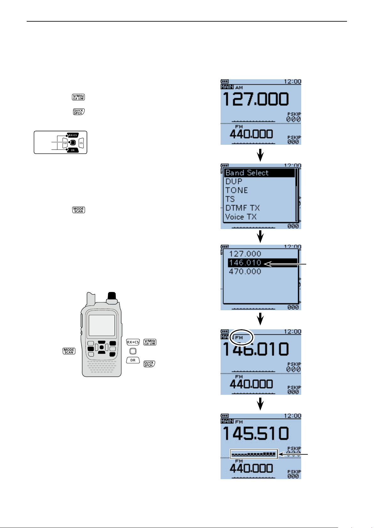
■ Receiving
Example: Receiving on 145.510 MHz
q Push [V/MHz] to select the VFO mode, if neces-
sary.
Push [QUICK] w to open the Quick Menu screen.
Push D-pad( e ) to select “Band Select,” and then
push D-pad(Ent).
Push D-pad( r ) to select the desired band.
• Example: “146.010”
• The last frequency operated on the band is displayed.
• The displayed frequency will appear after band selec-
tion.
Push D-pad(Ent) to save the setting and exit the t
Quick Menu screen.
Push [MODE] y to select the FM mode.
Rotate [DIAL] to select “145.510 MHz.” u
When a signal is received:
• The Squelch opens and audio is heard.
• The TX/RX indicator lights green.
• The S-meter shows the relative signal strength level.
[DIAL]
144 MHz band
S/RF-meter
5-9
Page 44
BASIC OPERATION
[DIAL]
[PTT]
TX/RX
indicator
Microphone
Previous view
5
■ Transmitting
CAUTION: Transmitting without an antenna will dam-
age the transceiver.
NOTE: To prevent interfering, hold down [SQL] to
listen on the channel before transmitting.
q Set the operating frequency. (p. 5-6)
• Transmitting can be done only when the 144 MHz or 430
MHz amateur band is selected as the MAIN band.
Hold down [LOW] w for 1 second to select the
transmit output power between S-Low, Low1, Low2,
Mid and High to suit your operating requirements.
• Or while holding down [LOW] , rotate [DIAL] to select
the output power.
• Lower output power during short-range communications
may reduce the possibility of interference to other stations, and will conserve battery power.
• “SLO”/“LO1”/ “LO2”/“MID” appears when S-low/low 1/low
2/mid power is selected.
• No icon appears when high power is selected.
Hold down [PTT] to transmit. e
• The TX/RX indicator lights red.
• The S/RF meter displays the output power level.
Speak at your normal voice level. r
• DO NOT hold the transceiver too close to your mouth or
speak too loudly. This may distort your speech.
Release [PTT] to receive. t
R WARNING! NEVER transmit for long periods of
time.
During prolonged transmissions at high power or mid
power, the transceiver radiates heat to protect itself
from overheating. The transceiver’s chassis will become hot and may cause a burn.
• To prevent the transceiver’s overheating, the default setting of the time-out timer function is set to 5 minutes (p. 16-
68). Be careful when the time-out timer function is turned
OFF or set to a long time period, and you transmit for long
periods.
DO NOT operate the transceiver in a situation that will
obstruct heat dissipation, especially if the transceiver
uses an external power supply. Heat dissipation may
be affected, and it may cause a burn, warp the casing
or damage the transceiver.
NOTE: When the transceiver becomes hot, the transceiver’s heat protection function gradually reduces
the output power to approximately 2.5 watts, then it
stops transmission after that. This is done to protect
the transceiver itself until it can cool down.
CONNECT to only the rated voltage range when using an external power supply.
❍ When the external DC power cable (13.5 V DC) is
: 5 W (High)/2.5 W (Mid)/1.0 W (Low2)/
❍ When the BP-273 is attached.
:
NOTE: When using the BP-273 battery case,
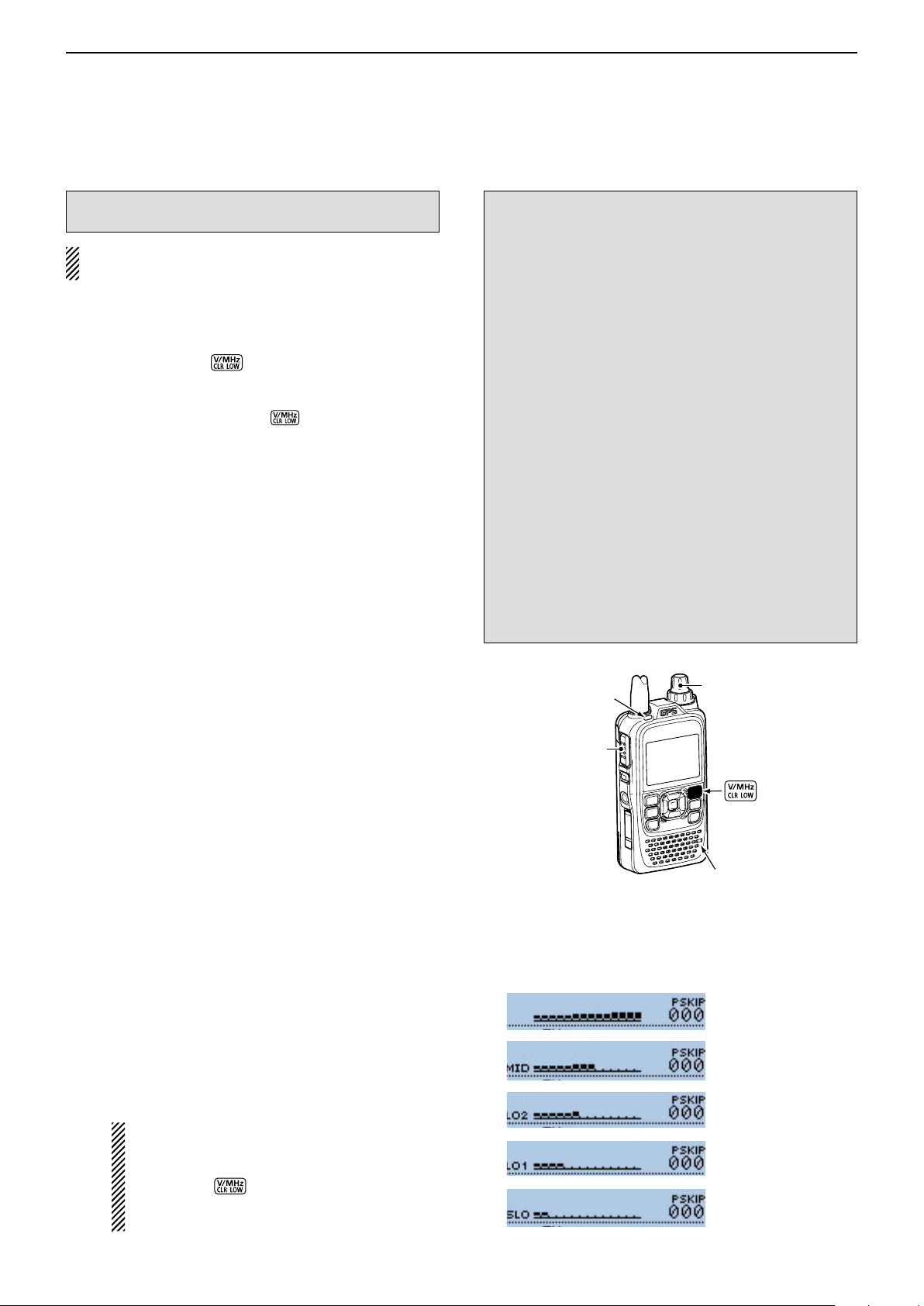
D About transmit power levels
connected or BP-271/BP-272 is attached.
0.5 W (Low1)/0.1 W (S-Low)
Approximately
0.1 W (S-LOW)
“SLO,” “LO1,” “LO2,” “MID” or no icon (high
power) appears on the display by holding
down [LOW] for 1 second. But “SLO” appears while transmitting, and
is limited to approximately 0.1 watts.
(approximately)
(fixed)
the output power
• Transmit power level display
High power (5 W)
Mid power (2.5 W)
Low2 power (1.0 W)
Low1 power (0.5 W)
S-Low power (0.1 W)
5-10
Page 45
BASIC OPERATION
D-pad
(�)
(Ent)
Previous view
5
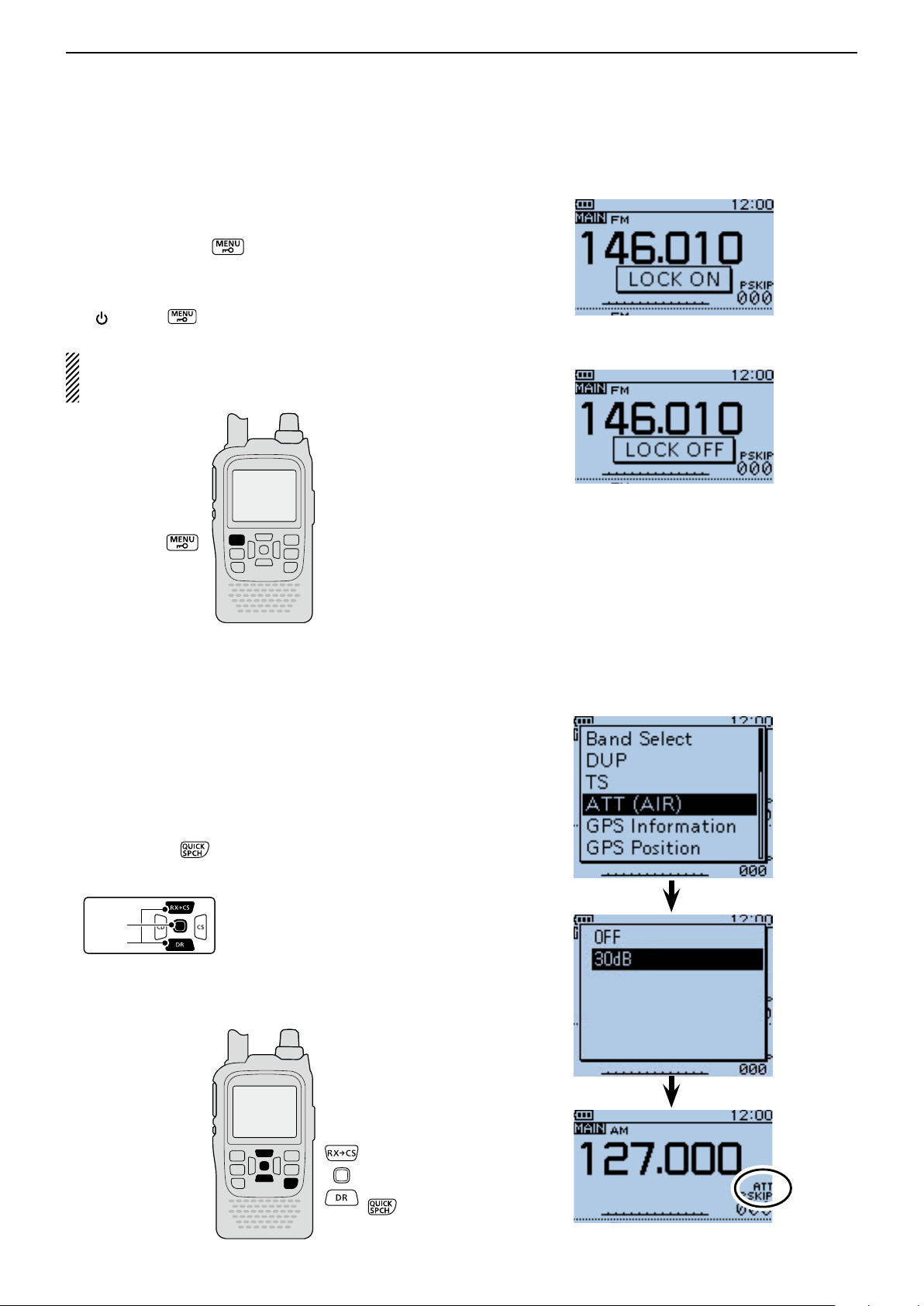
■ Key Lock function
Activate to prevent accidental frequency changes and
unnecessary function access.
Hold down [LOCK] ➥ for 1 second to turn the Key
Lock function ON or OFF.
• When the Key Lock function is activated and the locked key
or dial is pushed or rotated, “LOCK ON” appears.
• [ ], [LOCK] , [PTT], [SQL] and [VOL] can be used
while the lock function is activated.
Either or both the squelch control and volume control
can also be locked in the Function menu.
MENU > Function > Key Lock (p. 16-68)
The function is ON
The function is OFF
■ ATT (AIR) function
The attenuator reduces signal levels to prevent audio
distortion. This is useful when the transceiver receives
a very strong air band signal, or it is in very strong electromagnetic fields such as from a broadcasting station
near your location.
The attenuation is about 30 dB, and enabled when the
AIR band is selected.
Push [QUICK] q to open the Quick Menu screen.
Push D-pad( w ) to select “ATT (AIR),” and then push
D-pad(Ent).
Push D-pad( e ) to select “30dB.”
Push D-pad(Ent) to set, and exit the Quick Menu r
screen.
• “ATT” appears.
5-11
Page 46
BASIC OPERATION
D-pad
(�)
(Ent)
Previous view
5
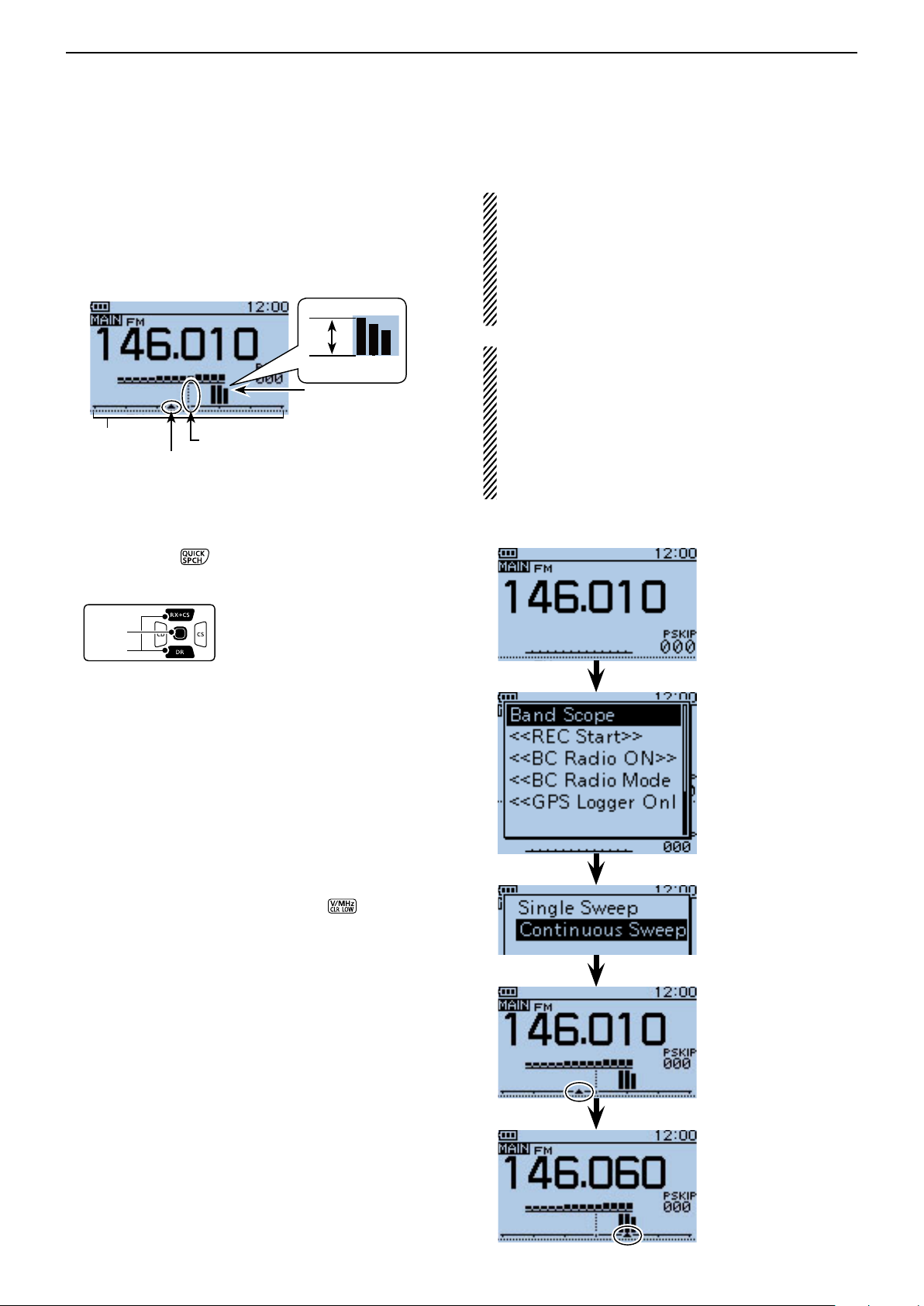
■ Band Scope function
The Band Scope function allows you to visually check a specified frequency range around the center frequency.
Example: The tuning step is set to 10 kHz, and a
strong signal is received on 146.060 MHz.
Strong level
Weak level
The signal on the
146.060 MHz
Band Scope display
Center frequency (Example: 146.010 MHz)
Sweep marker
D Sweep operation
Push [QUICK] q to open the Quick Menu screen.
Push D-pad( w ) to select “Band Scope,” and then
push D-pad(Ent).
About the sweep steps:
The specified tuning step (in VFO mode) or programmed
tuning step (in memory mode) is used during sweep.
If the tuning step is set to wide, the present signal may not
be displayed (may be skipped), even that is strong signal.
Thus we recommend to set the tuning step to the 20 kHz
or less to use the Band Scope function.
See page 5-5 for the Tuning step selection details.
• For the single watch operation within 144 MHz or 430
MHz band, the displayed frequency’s audio sounds during a sweep.
- In the AIR band, the displayed frequency’s audio does
not sound during a sweep, even if the single watch operation is selected.
• The audio output during a sweep can be turned OFF in
the MENU screen.
MENU > Sounds > Scope AF Output (p. 16-81)
Example: Continuous sweep on 146.010 MHz
Push D-pad( e ) to select the option between “Single
Sweep” and “Continuous Sweep.”
Push D-pad(Ent) to return to the frequency display r
and start sweeping.
• A single Sweep checks the specied frequency range
only one time.
• A continuous Sweep repeatedly checks the specied frequency range.
• Push D-pad(Ent) to stop sweeping and push again to
restart it.
• When the sweeping stops, rotate [DIAL] to move the
sweep marker to a detected signal; you can hear the signal audio.
• When the sweeping stops, push [CLR]
Band Scope function.
to cancel the
While continuously
sweeping
When the sweeping stops,
rotate [DIAL] to move the
sweep marker to a detected signal; you can hear
the signal audio.
5-12
Page 47
BASIC OPERATION
Previous view
5
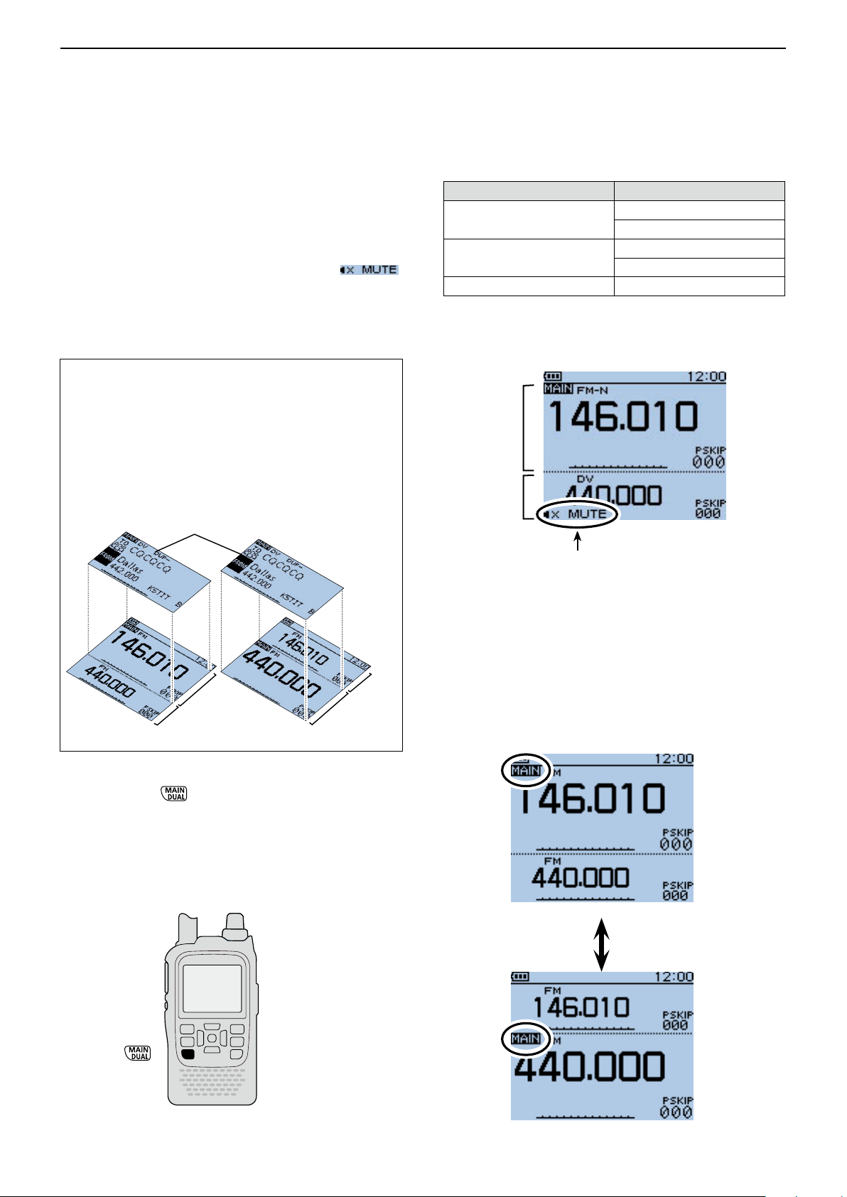
■ Dualwatch operation
Dualwatch operation simultaneously monitors two frequencies.
The ID-51A/E has two independent receiver circuits as
A band and B band.
Depending on the operating band or mode, the SUB
band audio signal is muted. In such case, “ ”
appears.
During the dualwatch operation, the audio output may
be interrupted when the frequency is switched while
scanning, or by other factors.
A/B band selection in the DR mode
The DR mode screen can be displayed on the A band
(upper) or B band (lower).
When the DR mode is displayed on the A band, and
the DR mode is selected in the B band, the previously
displayed frequency or memory before entering the
DR mode is displayed on the A band.
• Display image for the DR mode
DR mode screen
❍ SUB band mute status
MAIN band SUB band
DV mode
FM-N mode
AIR band AIR band
Example: MAIN band is FM-N mode.
SUB band is DV mode.
MAIN band
SUB band
DV mode
FM-N mode
DV mode
FM-N mode
A band
B band
A band
B band
D MAIN band selection
Push [MAIN] ➥ to alternately select upper half
band or lower half band as the MAIN band.
• “MAIN” appears on the MAIN band.
• “Band selection, operating frequency input using [DIAL],
operating mode selection, Memory channel selection,
memory write and band scope function can be made on
the MAIN band.
Appears when the SUB band
audio signal is muted.
MAIN band is upper half
MAIN band is lower half
5-13
Page 48

BASIC OPERATION
D-pad
(�)
(Ent)
Previous view
5
Dualwatch operation (Continued) ■
D Setting the volume for Dualwatch
The volume setting for Dualwatch can be set for both
bands simultaneously or for each band separately, in
the MENU screen.
Push [MENU] q to enter the Menu screen.
Push D-pad( w ) to select the root item (Sounds), and
then push D-pad(Ent) to go to the next level.
( MENU > Sounds > Volume Select)
Refer to the menu sequence shown directly above e
and push D-pad() to select, and then push Dpad(Ent) to enter, one or more times until the last
screen is displayed.
Push D-pad( r ) to select the desired option.
• All : The audio output level for the BC
Radio, A band and B band are adjusted at the same time.
• BC Radio Separate : The audio output level for the BC
Radio is independently adjusted.
The audio output level for A band
and B band are adjusted at the
same time.
• Separate : The audio output level for the BC
Radio, A band and B band are independently adjusted.
Push [MENU] t to exit the Menu screen.
When “All” or “BC Radio Separate” is selected:
Rotate [VOL] to adjust the audio level. ➥
• The audio output levels for A band and B band are adjusted at the same time:
When “Separate” is selected:
Push [MAIN] q for 1 second to select A band or B
band for the MAIN band.
Rotate [VOL] to adjust the audio level. w
• When the audio output level for A band and B band are
independently adjusted.
For example, even if the audio output level for A band is
adjusted, B band’s audio level stays at the original level.
[VOL]
5-14
Page 49
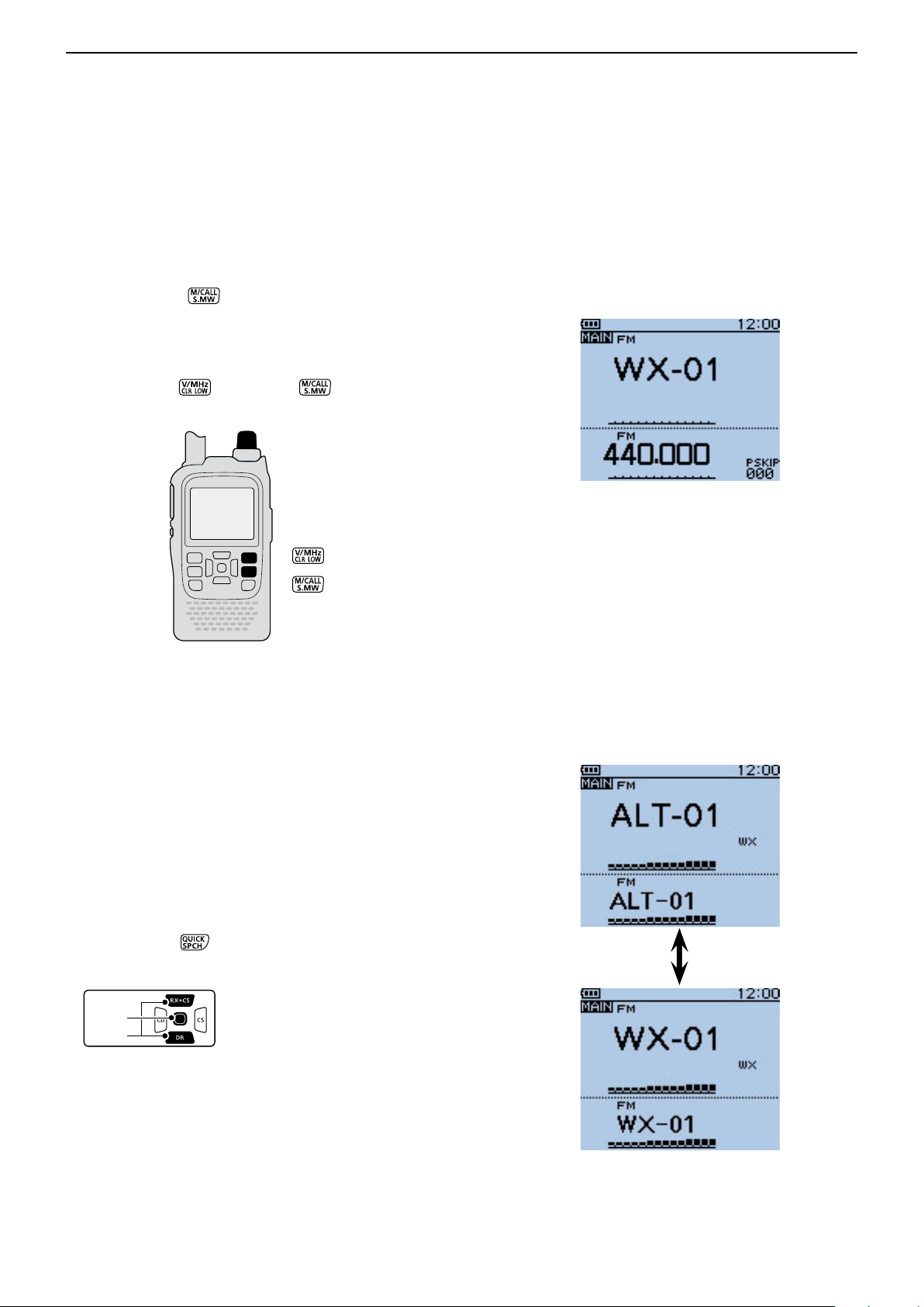
BASIC OPERATION
D-pad
(�)
(Ent)
Previous view
5
■ Weather channel operation (U.S.A. version transceivers only)
There are 10 weather channels for monitoring weather
channels from the NOAA (National Oceanographic and
Atmospheric Administration) broadcasts.
D Weather channel selection
Push [M/CALL] q one or more times to select the
weather channel mode.
• “WX” and the weather channel number appear.
Rotate [DIAL] to select the desired weather chan- w
nel.
Push [V/MHz] e or [M/CALL] to return to the
previous frequency or Memory channel.
[DIAL]
Weather channel mode
D Weather alert function
NOAA broadcast stations transmit weather alert tones
before important weather announcements.
When the weather alert function is turned ON, the selected weather channel is monitored every 5 seconds
for the announcement.
When the alert signal is detected, the “ALT” and the
WX channel are alternately displayed, and a beep tone
sounds until the transceiver is operated.
The previously selected (used) weather channel is
checked periodically during standby or while scanning.
Push [QUICK] q to open the Quick Menu screen.
Push D-pad( w ) to select “Weather Alert,” and then
push D-pad(Ent).
Push D-pad( e ) to select “ON” or “OFF.”
Push D-pad(Ent) to save the setting and exit the r
Quick Menu screen.
Set the desired standby mode. t
• “WX” appears when “ON” is selected in step e.
• Select the VFO, a Memory or Call channel.
• Scan or priority watch operation can also be selected.
When the alert signal is detected
5-15
Page 50

Section 6
Previous view
BC RADIO OPERATION
Basic operation ■ .................................................... 6-2
Descriptions D ..................................................... 6-2
Turning ON the BC Radio D ................................ 6-2
Listening to the BC Radio while monitoring two D
ham bands ....................................................... 6-3
Mode selection D ................................................ 6-3
Bank selection on the Memory bank mode D ..... 6-4
AM/FM radio mode selection D ........................... 6-5
To searching the broadcast signal D ................... 6-5
Attenuator function D .......................................... 6-6
Setting squelch level D ........................................ 6-7
Monitor function D ............................................... 6-7
Setting a tuning step (AM Only) D ...................... 6-8
Adding or editing a BC Radio memory ■ ................ 6-9
BC Radio Memory D .......................................... 6-9
Add a BC Radio memory D ................................ 6-9
Deleting a BC Radio memory D ........................ 6-12
Editing a BC radio memory D ........................... 6-13
Rearrange the display order of the BC Radio D
memory ......................................................... 6-14
Skip setting for the BC radio memory ■ ................ 6-15
Using the BC Radio Mode ■ ................................. 6-16
BC Radio setting ■ ............................................... 6-17
FM Antenna D ................................................... 6-17
Power Save (BC Radio) D ................................. 6-17
Auto Mute D ...................................................... 6-18
Volume Select D ............................................... 6-19
BC Radio Level D .............................................. 6-20
6-1
Page 51
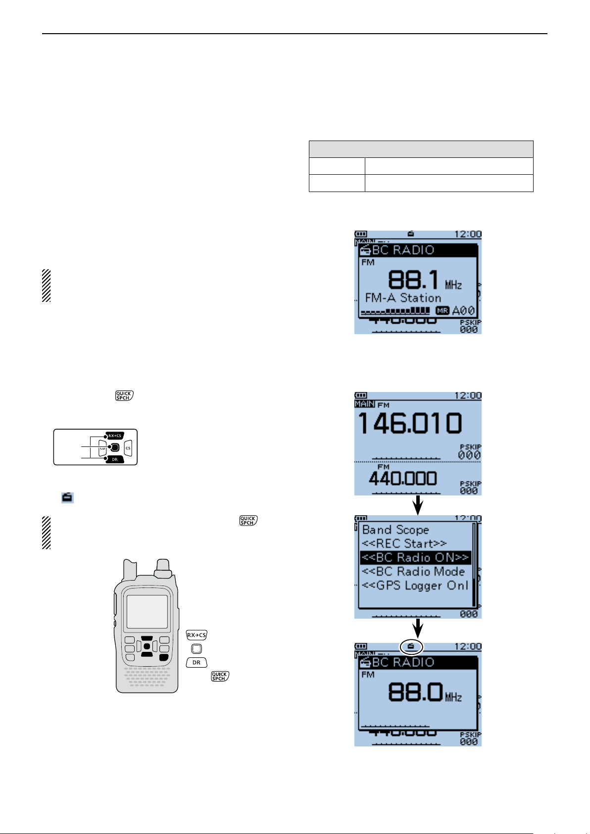
BC RADIO OPERATION
D-pad
(�)
(Ent)
Previous view
6
■ Basic operation
D Descriptions
You can listen to the AM or FM Broadcast (BC) Radio.
When the transceiver receives 2 amateur bands on the
MAIN band and SUB band, you can still listen to the
Broadcast (BC) Radio on the pop up window.
Up to 50 BC Radio memory channels can be programmed into each bank for easy memory management.
You can comfortably standby listening to the BC Radio.
Also, the transceiver can be used as just a BC Radio. In
this case, the other modes are in a sleep state.
The BC radio memory channel contents, described
in this manual, may differ from your transceiver’s preprogrammed memory.
Frequency range for the BC Radio
FM 76.0 MHz* to 108.0 MHz
AM 520 kHz to 1710 kHz
* The usable frequency range differs, according to the trans-
ceiver's version.
D Turning ON the BC Radio
Push [QUICK] q .
Push D-pad( w ) to select “<<BC Radio ON>>,” and
then push D-pad(Ent).
The BC Radio pop up window appears, and exits the e
Quick Menu screen.
• “ ” appears.
To turn OFF the BC Radio, push [QUICK] , and
then select “<<BC Radio OFF>>,” as described
above.
Example: While listening to FM-A Station
Appears
6-2
Page 52
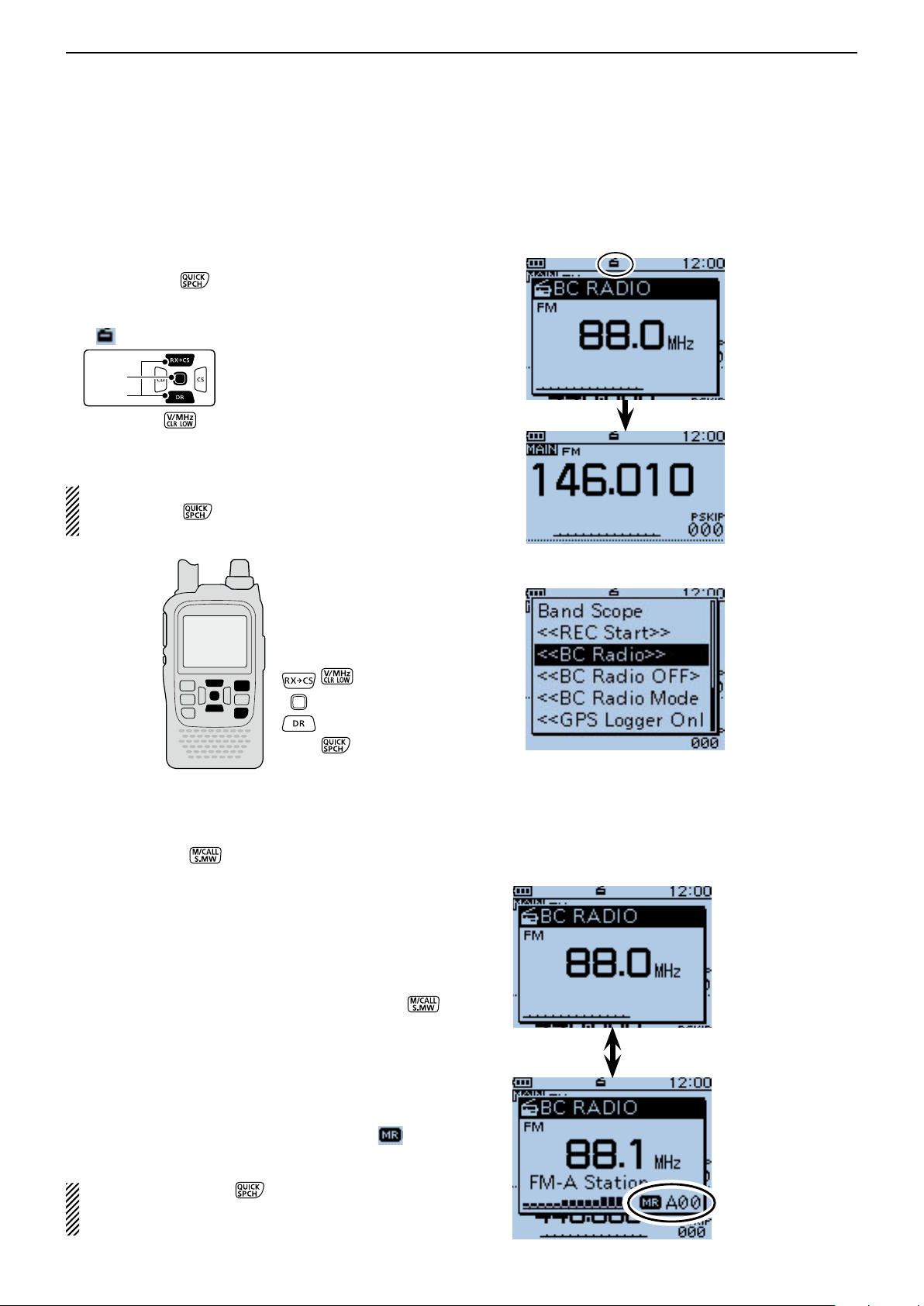
BC RADIO OPERATION
D-pad
(�)
(Ent)
Previous view
6
Basic operation (Continued) ■
D Listening to the BC Radio while monitoring two ham bands
When the transceiver receives 2 amateur bands on the
MAIN band and SUB band, you can still listen to the
BC Radio.
Push [QUICK] q .
Push D-pad( w ) to select “<<BC Radio ON>>,” and
then push D-pad(Ent).
• “ ” appears.
Push [CLR] e to turn OFF the BC Radio pop up
window.
• You can comfortably standby listening to the BC Radio.
NOTE: To show the BC Radio pop up window again,
push [QUICK] , and push D-pad() to select
“<<BC Radio>>,” then push D-pad(Ent).
Appears
BC Radio pop
up window
BC Radio pop up
window is OFF
(BC Radio is ON)
D Mode selection
When the BC Radio pop up window is displayed, q
push [M/CALL] to select between the Tuning
mode and the Memory bank mode.
Rotate [DIAL] to select the frequency or memory w
channel.
• Tuning mode
The BC Radio Tuning mode is used to set the desired
BC Radio frequency.
To save the selected frequency, hold down [S.MW]
for 1 second to program into the lowest memory channel of the selected bank.
• Memory bank mode
The BC Radio Memory bank mode is very useful to
quickly select often-used frequency settings.
When the Memory bank mode is selected, “ ” and
the selected memory channel number appear.
NOTE: Push [QUICK] , and select “VFO” to se-
lect the Tuning mode, or select “MR” to select the
Memory bank mode.
To show the BC Radio
pop up window again,
select “<<BC Radio>>.”
Tuning mode
Memory bank mode
6-3
Page 53
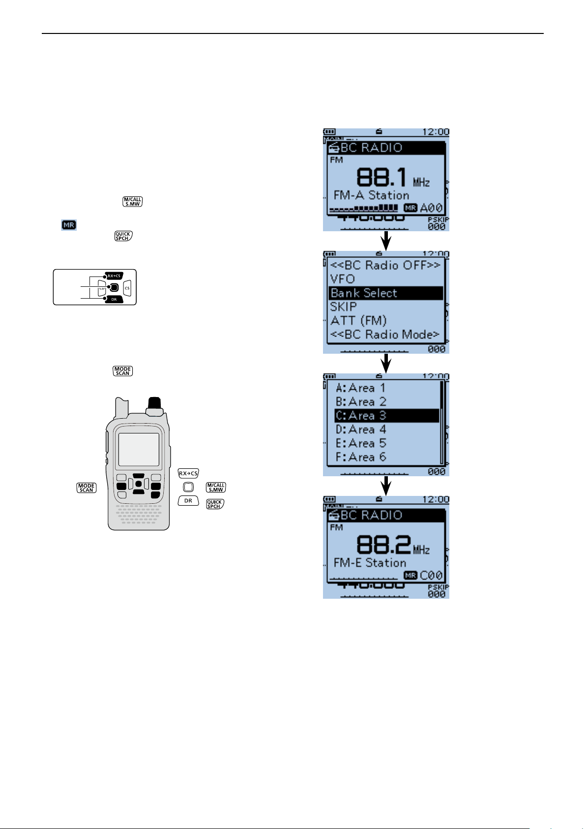
BC RADIO OPERATION
D-pad
(�)
(Ent)
Previous view
6
Basic operation (Continued) ■
D Bank selection on the Memory bank mode
Up to 50 BC Radio memory channels can be programmed into each bank for easy memory management.
If you switch the bank, other area channel can be selected.
Push [M/CALL] q to select the Memory bank
mode.
• “ ” and the selected memory channel number appear.
Push [QUICK] w .
Push D-pad( w ) to select “Bank Select,” and then
push D-pad(Ent).
Push D-pad( e ) to select the desired bank, and then
push D-pad(Ent).
The memory channel of the selected bank appears, r
and exits the Quick Menu screen.
• Rotate [DIAL] to select a memory channel.
• Push [MODE]
to select the FM or AM mode.
Memory bank mode
(Bank A)
Select “Bank C”
[DIAL]
The preprogrammed
channel of Bank C is
displayed
6-4
Page 54
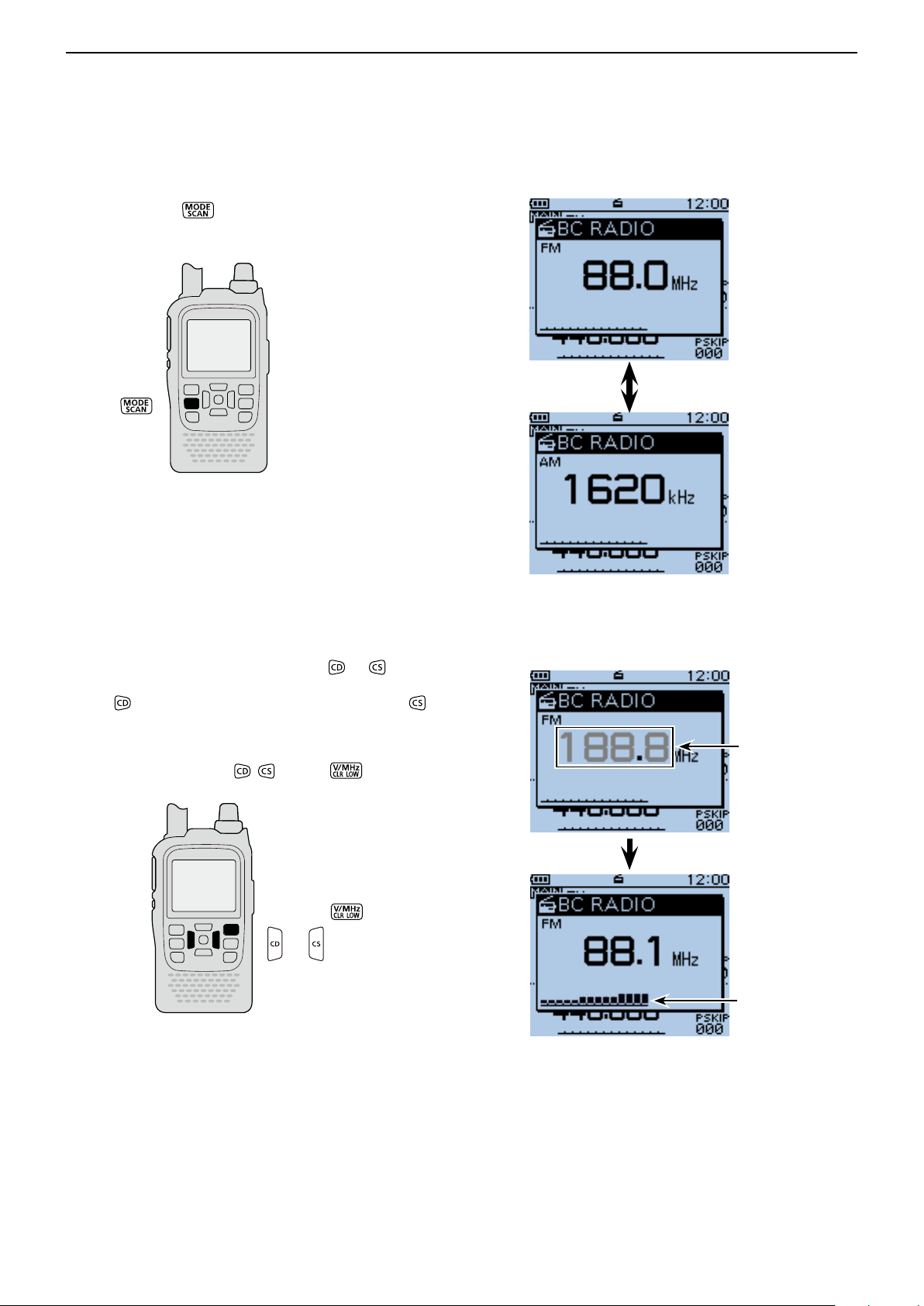
BC RADIO OPERATION
Previous view
6
Basic operation (Continued) ■
D AM/FM radio mode selection
Push [MODE] ➥ to select the AM or FM radio
mode.
FM mode
AM mode
D To searching the broadcast signal
While in the Tuning mode, hold down or to start
searching the broadcast signal.
• When is held down, a down scan starts, and when is
held down, up scan starts.
• When a signal is received, the scanning stops on the fre-
quency.
• To cancel scanning, push
, or [CLR] .
While searching a signal
When a signal
is received
6-5
Page 55

BC RADIO OPERATION
D-pad
(�)
(Ent)
Previous view
6
Basic operation (Continued) ■
D Attenuator function
The attenuator reduces signal levels to prevent audio
distortion.
This is useful when the transceiver receives a very
strong AM or FM BC Radio signal, or it is in very strong
electromagnetic fields such as from a broadcasting station near your location.
The attenuator can be set in both the AM and FM
mode.
Push [MODE] q to select the desired AM or FM
mode.
Push [QUICK] w .
Push D-pad( e ) to select “ATT (FM),” and then push
D-pad(Ent).
• When the AM mode is selected in step q, select “ATT
(AM).”
Push D-pad( r ) to select the attenuator.
• ATT (FM)
OFF : The attenuator is OFF.
30dB : The attenuation is about 30 dB.
• ATT (AM)
OFF : The attenuator is OFF.
Auto : The attenuation is automatically switched be-
tween OFF and 30 dB (maximum), depend-
ing on the received signal strength level.
30dB : The attenuation is set to 30 dB.
50dB : The attenuation is set to 50 dB.
Push D-pad(Ent) to save, and exit the Quick Menu t
screen.
• When the attenuator is ON, “ATT” appears on the BC
Radio pop up window.
Appears
6-6
Page 56
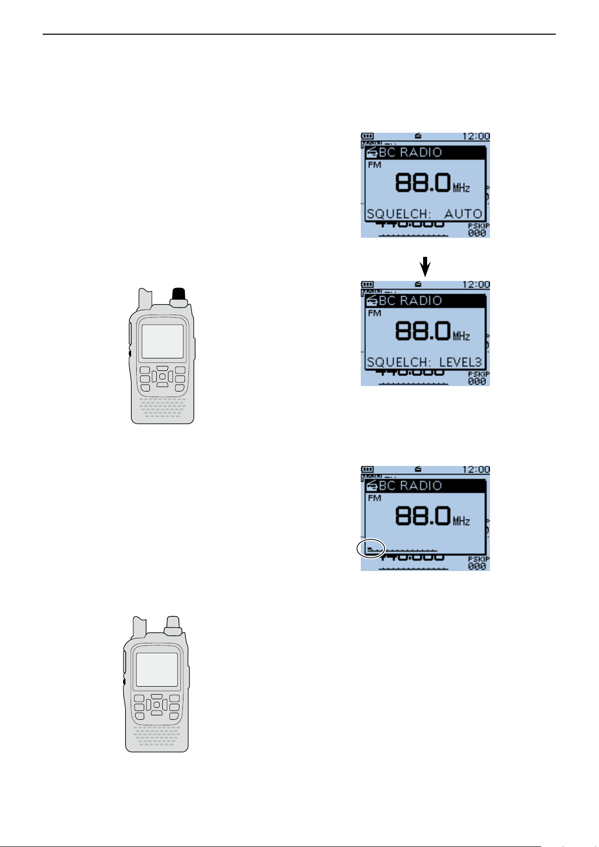
BC RADIO OPERATION
Previous view
6
Basic operation (Continued) ■
D Setting squelch level
The squelch level can be set only for the BC radio.
While holding down [SQL], rotate [DIAL] one click to q
display the squelch level. (Default: AUTO)
While holding down [SQL], rotate [DIAL] to select the w
squelch level.
•“LEVEL1”isloosesquelch(forweaksignals)and“LEV-
EL3”istightsquelch(forstrongsignals).
•“AUTO” shows automatic level adjustment by a noise
pulsecountingsystem.
•“OPEN”showsacontinuouslyopensetting.
[DIAL]
When“AUTO”isselected.
[SQL]
D Monitor function
This function is used to listen to weak BC Radio signals without disturbing the squelch setting, or having to
manuallyopenthesquelch.
Holddown[SQL] to monitortheoperatingfrequen- ➥
cy.
•The1stsegmentoftheS-meterblinks.
The [SQL] key can be set to ‘sticky’ operation in Func-
tionmenu.
MENU > Function > Monitor(p.16-66)
WhenLevel3 (Maximum)
is selected.
Blinks
[SQL]
6-7
Page 57

BC RADIO OPERATION
D-pad
(�)
(Ent)
Previous view
6
Basic operation (Continued) ■
D Setting a tuning step (AM Only)
If you select the BC Radio frequency by rotating [DIAL]
in the Tuning mode, the frequency changes in the selected tuning step.
Push [MODE] q to select the AM mode.
Push [QUICK] w .
Push D-pad( e ) to select “TS,” and then push D-
pad(Ent).
Push D-pad( r ) to select the desired tuning step be-
tween 1.0 kHz, 9.0 kHz and 10.0 kHz.
Push D-pad(Ent) to save, and exit the Quick Menu t
screen.
When 10.0 kHz
step is selected.
The frequency changes in the
selected tuning step.
6-8
Page 58

BC RADIO OPERATION
D-pad
(�)
(Ent)
Previous view
6
■ Adding or editing a BC Radio memory
D BC Radio Memory
A total of 26 banks are selectable for BC Radio Memory. You can assign up to 50 BC Radio memory channels to each bank, for easy memory management. (A
maximum of 500 memories can be assigned to the BC
Radio Memory.)
Some area stations are preloaded into the BC Radio
memory for easy memory management.
The BC radio memory channel contents, described
in this manual, may differ from your transceiver’s preprogrammed memory.
D Add a BC Radio memory
Adding a BC Radio Memory and entering the edit 1.
mode
q Push [MENU]
w Push D-pad() to select the root item (“BC Radio”),
and then push D-pad(Ent).
.
BC Radio Memory
A: Area 1
B: Area 2
C: Area 3
D: Area 4
Z:
(Example)
FM
AM
FM-A Station
FM-B Station
FM-C Station
AM-A Station
AM-B Station
AM-C Station
e Push D-pad() to select a desired bank, and then
push D-pad(Ent).
r Push D-pad() to select the desired radio mode (AM
or FM) to be programmed.
t Push [QUICK] .
y Push D-pad() to select “Add,” and then push D-
pad(Ent).
• The BC RADIO MEM EDIT screen is displayed.
BC RADIO MEMORY
screen is displayed.
When no memory is
programmed, “-- Blank --”
appears.
Select “Add”
Continued on the next page ☞
6-9
Page 59
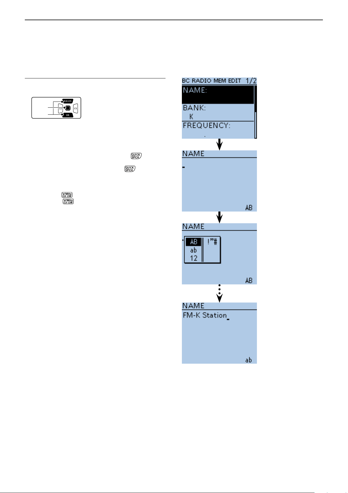
BC RADIO OPERATION
D-pad
(�)
(Ent)
Previous view
6
Adding or editing BC Radio memory ■ (Continued)
BC Radio Memory name programming 2.
u Push D-pad() to select “NAME,” and then push D-
pad(Ent).
i Rotate [DIAL] to select the first character.
• Selectable input characters are Upper case letters, Low-
er case letters, Numbers or Symbols.
• The selected character blinks.
• Push D-pad() to move the cursor backward or forward.
• While selecting a character, push [QUICK]
the character to an upper case or lower case letter.
• While selecting a digit, push [QUICK]
input mode selection window.
• A space can be entered, in any input mode selected.
• Rotate [DIAL] counter clockwise to enter a space.
• Push [CLR]
down [CLR]
first to the right, and then to the left of the cursor.
• See page 2-7 for programming details.
to delete the selected character, or hold
to continuously delete the characters,
to change
to open the
o Push D-pad() to move the cursor to the second
digit.
!0 Repeat steps i and o to enter a BC Radio Memory
name of up to 16 characters, including spaces.
!1 After entering the name, push D-pad(Ent).
Character
type selection
screen
(Example)
When entering
“FM-K Station”
Continued on the next page ☞
6-10
Page 60

BC RADIO OPERATION
D-pad
(�)
(Ent)
Previous view
6
Adding or editing BC Radio memory ■ (Continued)
Frequency programming3.
!2 Push D-pad() to select “FREQUENCY,” and then
push D-pad(Ent).
• A cursor appears and blinks.
!3 Rotate [DIAL] to input the frequency.
• AM: 520 to 1710 kHz
• FM: 76.0 to 108.0 MHz
!4 Push D-pad() to move the cursor backward or for-
ward to edit the frequency.
!5 Repeat steps !3 and !4 to enter the frequency.
!6 After entering, push D-pad(Ent).
Skip setting4.
(Example)
When entering
“88.9”
!7 Push D-pad() to select “SKIP,” and then push D-
pad(Ent).
!8 Push D-pad() to select whether or not to use the
channel in the BC Radio memory.
• OFF: You can select the channel in the BC Radio
memory.
• Skip: The channel does not appear in the BC Radio
memory.
!9 After selecting, push D-pad(Ent).
Writing BC Radio Memory5.
@0 Push D-pad() to select “<<Add Write>>,” and then
push D-pad(Ent).
• If a previously added BC Radio memory is edited, select
“<<Overwrite>>.”
@1 Push D-pad() to select “YES,” and then push D-
pad(Ent).
Select
To cancel the programmed data:
To cancel the programmed q
data, push [CLR]
display “Cancel edit?.”
Push D-pad( w
“YES,” and then push Dpad(Ent) to cancel programming and return to
the BC Radio Memory’s
channel list screen.
to
) to select
(Example)
When “FM-K Station” is
programmed in Bank K.
The list of BC Radio Bank K
is displayed.
6-11
Page 61
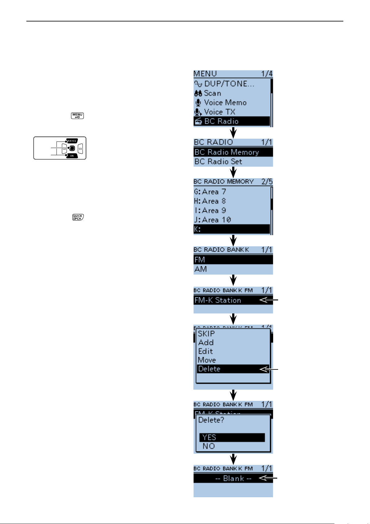
BC RADIO OPERATION
D-pad
(�)
(Ent)
Previous view
6
Adding or editing BC Radio memory ■ (Continued)
D Deleting a BC Radio memory
All the contents of a BC Radio memory can be deleted.
Please note that deleted memory cannot be restored.
Push [MENU] q .
Push D-pad( w ) to select the root item (BC Radio),
and then push D-pad(Ent).
Push D-pad( e ) to select “BC Radio Memory,” and
then push D-pad(Ent).
Push D-pad( r ) to select the BC Radio group that
includes the memory you want to delete, and then
push D-pad(Ent).
Push D-pad( t ) to select the memory channel to be
deleted.
Push [QUICK] y .
Push D-pad( u ) to select “Delete,” and then D-
pad(Ent).
Push D-pad( i ) to select “YES,” and then push D-
pad(Ent).
• The selected BC Radio memory is deleted.
Select the channel
to be deleted.
Select
“FM-K Station” is
deleted, and “-- Blank --”
is displayed in Bank K.
6-12
Page 62

BC RADIO OPERATION
D-pad
(�)
(Ent)
Previous view
6
Adding or editing BC Radio memory ■ (Continued)
D Editing a BC radio memory
This function reprograms a BC radio memory data. This
is useful when already-programmed data is incorrect,
has changed or some data should be added to the list.
Push [MENU] q
.
Push D-pad( w ) to select the root item (“BC Radio”),
and then push D-pad(Ent).
Push D-pad( e ) to select “BC Radio Memory,” and
then push D-pad(Ent).
Push D-pad( r ) to select the BC Radio bank that in-
cludes the memory you want to edit, and then push
D-pad(Ent).
Push D-pad( t ) to select the memory to be edited.
Push [QUICK] y .
Push D-pad( u ) to select “Edit.”
Push D-pad( i ) to select the desired item, and then
push D-pad(Ent).
• See pages 6-9 to 6-11 for programming details.
After programming, the display returns to the BC o
RADIO MEM EDIT screen.
!0 Push D-pad() to select “<<Overwrite>>,” and then
push D-pad(Ent).
!1 Push D-pad() to select “YES,” and then push D-
pad(Ent).
• The programmed contents are overwritten in the BC ra-
dio memory, and the transceiver returns to the BC Radio
bank screen.
Example:
“FM-K Station”
is edited.
6-13
Page 63

BC RADIO OPERATION
D-pad
(�)
(Ent)
Previous view
6
Adding or editing BC Radio memory ■ (Continued)
D Rearrange the display order of the BC Radio memory
You can move the programmed BC Radio memory to
rearrange their display order in the selected BC Radio
memory bank.
The programmed BC Radio memory cannot be moved
out of their assigned memory bank.
Push [MENU] q .
Push D-pad( w ) to select the root item (“BC Radio”),
and then push D-pad(Ent).
Push D-pad( e ) to select “BC Radio Memory,” and
then push D-pad(Ent).
Push D-pad( r ) to select the BC Radio memory
bank that includes the BC Radio memory you want
to move, and then push D-pad(Ent).
Push D-pad( t ) to select the BC Radio memory to
be moved.
Push [QUICK] y .
Push D-pad( u ) to select “Move,” and then push D-
pad(Ent).
• “DESTINATION” blinks on the upper left of the LCD.
i Push D-pad() to select the location to insert the
memory you want to move, which will be above the
memory name selected in this screen, and then push
D-pad(Ent).
• The selected memory contents are inserted to above the
destination memory name.
• When “<<Move End>>” is selected, the selected memory
contents are moved to the bottom of the BC Radio memory bank.
Select the memory
to be moved.
Blinks
Select the
destination
“FM-A Station”
is moved to the
bottom.
6-14
Page 64

BC RADIO OPERATION
D-pad
(�)
(Ent)
Previous view
6
■ Skip setting for the BC radio memory
You can set the undesired frequency to skip targets.
Push [MENU] q .
Push D-pad( w ) to select the root item (“BC Radio”),
and then push D-pad(Ent).
Push D-pad( e ) to select “BC Radio Memory,” and
then push D-pad(Ent).
Push D-pad( r ) to select the BC Radio memory bank
that includes the BC Radio memory you want to set
the skip setting on, and then push D-pad(Ent).
Push D-pad( t ) to select the BC Radio memory to
be skipped.
Push [QUICK] y .
Push D-pad( u ) to select “SKIP,” and then push D-
pad(Ent).
• “SKIP” appears on the selected repeater.
• Push [QUICK]
D-pad(Ent) to cancel the skip setting.
and select “SKIP” again, then push
In the BC radio window,
push [QUICK] , and select “SKIP” also set the skip
setting.
Select the memory
to be skipped.
Appears
6-15
Page 65
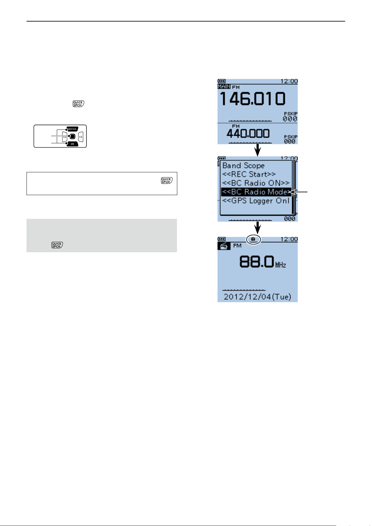
BC RADIO OPERATION
D-pad
(�)
(Ent)
Previous view
6
■ Using the BC Radio Mode
The transceiver has an exclusive BC Radio mode
where only the BC Radio functions.
Push [QUICK] q .
Push D-pad( w ) to select “<<BC Radio Mode>>,”
then push D-pad(Ent).
• BC radio mode screen is displayed.
To cancel the BC Radio mode, push [QUICK] ,
and select “<<Normal Mode>>.”
Select
In the exclusive BC Radio mode, the other modes are
in a sleep state.
To operate the transceiver in a normal way, push
[QUICK] , and then select “<<Normal Mode>>.”
Appears
BC Radio Mode screen
6-16
Page 66

BC RADIO OPERATION
D-pad
(�)
(Ent)
D-pad
(�)
(Ent)
Previous view
6
■ BC Radio setting
D FM Antenna
Select the desired antenna for FM radio.
Push [MENU] q .
Push D-pad( w ) to select the root item (“BC Radio”),
and then push D-pad(Ent) to go to the next screen.
(MENU > BC Radio > BC Radio Set> FM Antenna)
Refer to the menu sequence shown directly above e
and push D-pad() to select, and then D-pad(Ent)
to enter, one or more times until the last screen is
displayed.
Push D-pad( r ) to select the desired antenna used
for the FM radio
• External : The external antenna is used.
• Earphone : The earphone antenna is used.
Push [MENU] t to exit the MENU screen.
D Power Save (BC Radio)
Set the power save function to reduce current drain and
conserve battery power when the BC Radio is ON.
Push [MENU] q .
Push D-pad( w ) to select the root item (“BC Radio”),
and then push D-pad(Ent) to go to the next screen.
( MENU > BC Radio > BC Radio Set> Power Save
(BC Radio))
Refer to the menu sequence shown directly above e
and push D-pad() to select, and then D-pad(Ent)
to enter, one or more times until the last screen is
displayed.
Push D-pad( r ) to set the power save function when
the BC Radio is ON.
• OFF : The power save function is OFF.
• ON : When the BC Radio is ON, and when no sig-
nal is received for 5 seconds, this function
is activated in a 1:3 ratio (300 milliseconds:
900 milliseconds) during FM mode opera-
tion, or 1:1 ratio (2000 milliseconds: 2000
milliseconds) during AM mode operation.
Push [MENU] t to exit the MENU screen.
NOTE: This function is disabled when the external
power supply is used.
6-17
Page 67

BC RADIO OPERATION
D-pad
(�)
(Ent)
Previous view
6
BC Radio setting (Continued) ■
D Auto Mute
This setting is enabled when you listen to the BC Radio
in the background.
Push [MENU] q .
Push D-pad( w ) to select the root item (“BC Radio”),
and then push D-pad(Ent) to go to the next screen.
(MENU > BC Radio > BC Radio Set> Auto Mute)
Refer to the menu sequence shown directly above e
and push D-pad() to select, and then D-pad(Ent)
to enter, one or more times until the last screen is
displayed.
Push D-pad( r ) to select the Auto Mute timer to be-
tween 0 and 10 seconds (in 1 second steps), or
OFF.
• OFF : The Auto Mute function is OFF.
The BC Radio audio is not muted even
if the transceiver receives a signal on
the MAIN or SUB band.
The BC Radio audio is muted when the
transceiver transmits.
• 0 to 10sec : The BC Radio audio is automatically
muted when the transceiver transmits
or receives on the MAIN or SUB band.
After transmitting or receiving, the Auto
Mute timer starts. After the timer period
ends, you can listen to the BC Radio.
Push [MENU] t to exit the MENU screen.
6-18
Page 68
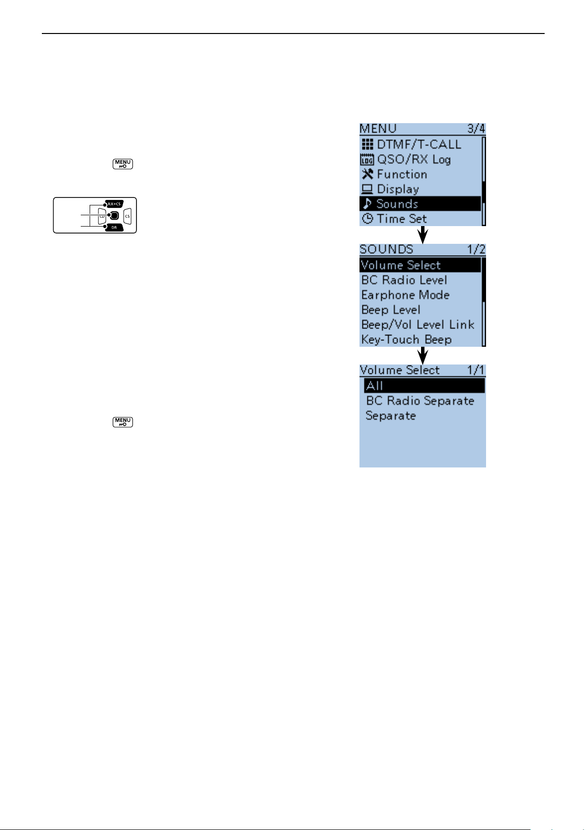
BC RADIO OPERATION
D-pad
(�)
(Ent)
Previous view
6
BC Radio setting (Continued) ■
D Volume Select
Select to adjust the audio output level of all bands together, all separately, or just the BC Radio separately.
Push [MENU] q .
Push D-pad( w ) to select the root item (“Sounds”),
and then push D-pad(Ent).
Push D-pad( e ) to select “Volume Select,” and then
push D-pad(Ent).
Push D-pad( r ) to select whether or not to indepen-
dently adjust the audio output level.
• All : The audio output level of the BC Radio,
A band and B band are adjusted at the
together.
• BC Radio Separate
: The audio output level of the BC Radio
is separately adjusted.
The audio output level of A band and B
band are adjusted together.
• Separate : The audio output level of the BC Radio,
A band and B band are separately adjusted.
Push [MENU] t to exit the MENU screen.
6-19
Page 69
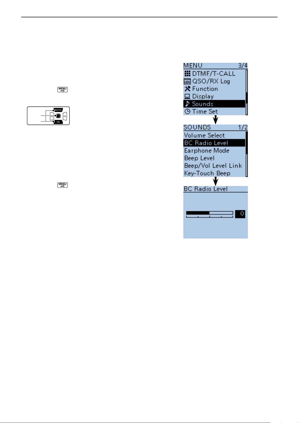
BC RADIO OPERATION
D-pad
(�)
(Ent)
Previous view
6
BC Radio setting (Continued) ■
D BC Radio Level
Set the initial audio output level difference between the
BC Radio and the A and B bands when “All” is set in
“Volume Select.” (p. 16-78)
Push [MENU] q .
Push D-pad( w ) to select the root item (“Sounds”),
and then push D-pad(Ent).
Push D-pad( e ) to select “BC Radio Level,” and then
push D-pad(Ent).
Rotate [DIAL] to adjust. r
• +5 to +1 : The BC Radio audio output level is higher
than the A and B bands audio.
• 0 : The BC Radio audio output level is same
as the A and B bands audio.
• –1 to –5 : The BC Radio audio output level is lower
than the A and B bands audio.
Push [MENU] t to exit the MENU screen.
6-20
Page 70

Section 7
Previous view
D-STAR INTRODUCTION
D-STAR Intoroduction ■ .......................................... 7-2
About the DR (D-STAR Repeater) mode ■ ............. 7-2
Communication Form in the DR mode ■ ................ 7-3
To begin the digital mode communication except in the DR mode
To begin the digital mode communication except in the
DR mode, you can use the VFO mode, Memory mode
and Call channel mode.
This manual describes focusing on the DR mode operation which can be set up easily, and if you want to
use another mode, see the procedures as described
to the right.
IMPORTANT!
• The repeater list, described in this manual, may differ from your transceiver’s preloaded contents.
• Although Japanese repeaters are used in the setting examples, the Japanese repeater node (port) letters are dif-
ferent from other country’s.
Be sure to add a repeater node letter as the 8th digit in the call sign field after a repeater call sign, according to
the repeater frequency band, as shown below.
1200 MHz : A (B in Japan)
430 MHz : B (A in Japan)
144 MHz : C (no D-STAR repeaters in Japan)
For a Local area call or Gateway call:
Set the access repeater’s frequency. (p. 15-2) q
Set the frequency offset. (p. 15-4) w
Set the Duplex direction. (p. 15-5) e
Set the call signs. (p. 16-48) r
For a Simplex call:
Set the operating frequency. q
Set the call sign. (p. 16-48) w
7-1
Page 71
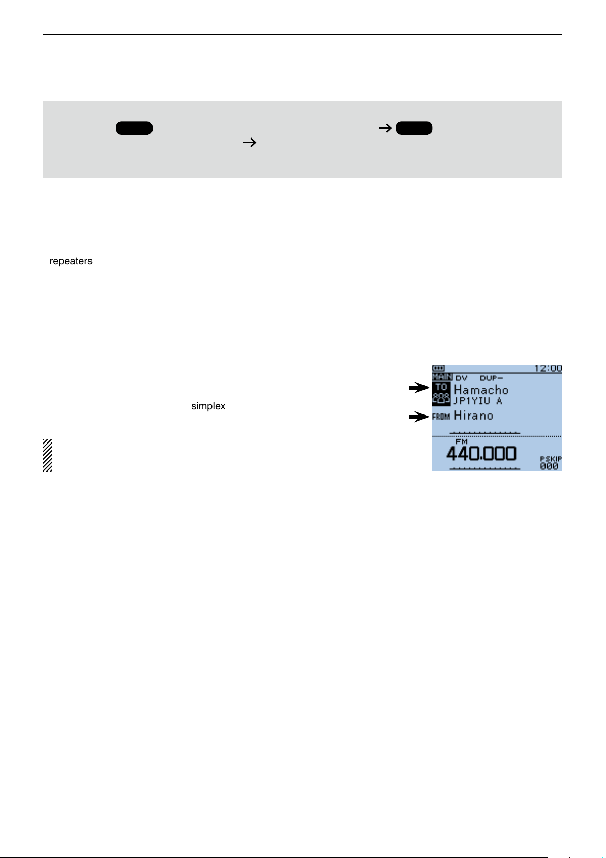
D-STAR INTRODUCTION
Previous view
7
Before starting D-STAR, the following steps are needed.
STEP 1
IMPORTANT!
(MY) to a gateway repeater. You have completed the steps!!
See the Basic Instruction (printed manual) for details.
D-STAR Intoroduction ■
Entering your call sign (MY) into the transceiver.
STEP 2
Registering your call sign
• In the original D-STAR (Digital Smart Technologies for
Amateur Radio) plan, JARL envisioned a system of
repeaters grouped together into Zones.
• The D-STAR repeater enables you to call a HAM station in another area through the internet.
About the DR (D-STAR Repeater) mode ■
The DR (D-STAR Repeater) mode is one mode you can
use for D-STAR repeater operation. In this mode, you
can select the preprogrammed repeater or frequency in
“FROM” (the access repeater or simplex), and UR call
sign in “TO” (destination), as shown to the right.
NOTE: If the repeater, set to “FROM” (Access Repeater) has no Gateway call sign, you cannot make
a gateway call.
• The transceiver can be operated in the digital voice
mode, including low-speed data operation, for both
transmit and receive. It has a built-in GPS receiver to
transmit and receive position data.
Destination
(Repeater/Station)
Access repeater
or Simplex
In the DR mode
7-2
Page 72
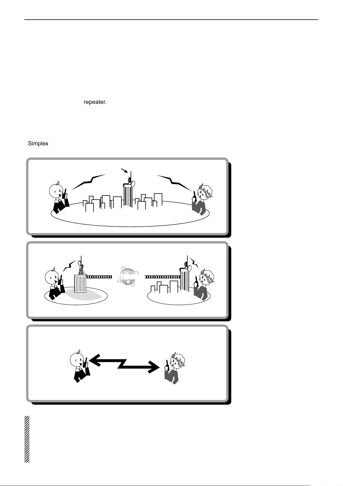
D-STAR INTRODUCTION
INTERNET
Previous view
7
■ Communication Form in the DR mode
In the DR mode, the transceiver has three communication forms, as shown below.
• Local area call : To call through your local area (ac-
cess) repeater.
• Gateway call : To call through your local area (ac-
cess) repeater, repeater gateway and
the internet to your destination repeater or individual station’s last used
repeater, using call sign routing.
• Simplex call : To call another station not using a re-
peater.
Local area call
Gateway call
Hirano area Sapporo area
Simplex call
Access repeater
Hirano
repeater
Hamacho
repeater
Hamacho area
Sapporo
repeater
NOTE:
• Programming the repeater list is required for DR mode operation. (pp. 9-23 to 9-31)
• Before operating in the DV mode, be sure to check whether the repeater is busy, or not. If the repeater is busy,
• The transceiver has a Time-Out Timer function for digital repeater operation. The timer limits a continuous trans-
wait until it is clear, or ask for a “break” using a method acceptable to your local procedures.
mission to approximately 10 minutes. Warning beeps will sound approximately 30 seconds before time-out and
then again immediately before time-out.
7-3
Page 73

Section 8
Previous view
D-STAR OPERATION <BASIC>
“FROM” (Access repeater) setting ■ ....................... 8-2
U D sing the preloaded repeater list .................... 8-3
U D sing the DR mode scan ................................ 8-4
U D sing the Repeater Search function ............... 8-5
U D sing the TX History ....................................... 8-7
“TO” (Destination) setting ■ .................................... 8-8
Using the “Local CQ” (Local Area call) D ............ 8-9
Using the D “Gateway CQ” (Gateway call) ........ 8-10
U D sing the “Your Call Sign” .............................. 8-11
U D sing the RX History ..................................... 8-12
U D sing the TX History ..................................... 8-13
D D irectly inputting (UR) ................................... 8-14
D D irectly inputting (RPT) ................................. 8-15
IMPORTANT!
• The repeater list, described in this manual, may differ from your transceiver’s preloaded contents.
• Although Japanese repeaters are used in the setting examples, the Japanese repeater node (port) letters are dif-
ferent from other country’s.
Be sure to add a repeater node letter as the 8th digit in the call sign field after a repeater call sign, according to
the repeater frequency band, as shown below.
1200 MHz : A (B in Japan)
430 MHz : B (A in Japan)
144 MHz : C (no D-STAR repeaters in Japan)
8-1
Page 74

D-STAR OPERATION <BASIC>
Previous view
8
■ “FROM” (Access repeater) setting
Your access repeater must be set to “FROM” when you
transmit a call in the DR mode.
You have four ways to set the access repeater.
Click the title shown below to jump to the specified
page.
• When you know your access repeater
From the repeater list (p. 8-3)
Select the repeater preloaded in your transceiver’s
repeater list.*
“Hirano” repeater
is set in “FROM.”
• When you don't know which repeater you can access.
Search for a repeater using the DR mode scan (p. 8-4)
Searches for DV signals from a repeater or a simplex
frequency.
Blinks
Search for the nearest repeater (p. 8-5)
The transceiver searches the nearest repeater by using your own and the repeater’s position.
• When the “FROM” data is stored in the TX History.
While DR mode scanning
Setting from the TX History (p. 8-7)
When you transmit a call in the DR mode, “FROM”
(the access repeater) data is stored in the TX History.
You can select the access repeater from the record.
8-2
Page 75
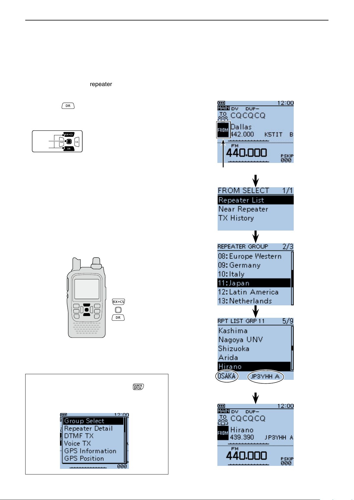
D-STAR OPERATION <BASIC>
D-pad
(�)
(Ent)
Previous view
8
“FROM” (Access repeater) setting (Continued) ■
D Using the preloaded repeater list
For easy operation, the repeater list is preloaded into
your transceiver.
Hold down q for 1 second.
• The DR mode is selected.
Push D-pad( w ) to select “FROM,” and then push D-
pad(Ent).
Push D-pad( e ) to select “Repeater List,” and then
push D-pad(Ent).
Push D-pad( r ) to select the repeater group where
your access repeater is listed, and then push Dpad(Ent).
• Example: “11: Japan”
• The repeater list, described in this manual, may differ
from your transceiver’s preloaded list.
Push D-pad( t ) to select your access repeater, and
then push D-pad(Ent).
• Example: “Hirano”
If the selected repeater name is displayed in “FROM” y
on the DR mode screen, the access repeater setting
is completed.
Example: Select the “Hirano” repeater in Japan
from the repeater list.
“FROM” is selected.
How to switch the repeater group:
• You can switch the repeater group using D-pad()
While in the DR mode, push [QUICK] ➥ to open
the Quick menu. Then push D-pad() to select
“Group Select.”
8-3
Repeater area
Repeater call sign
Completed
Page 76
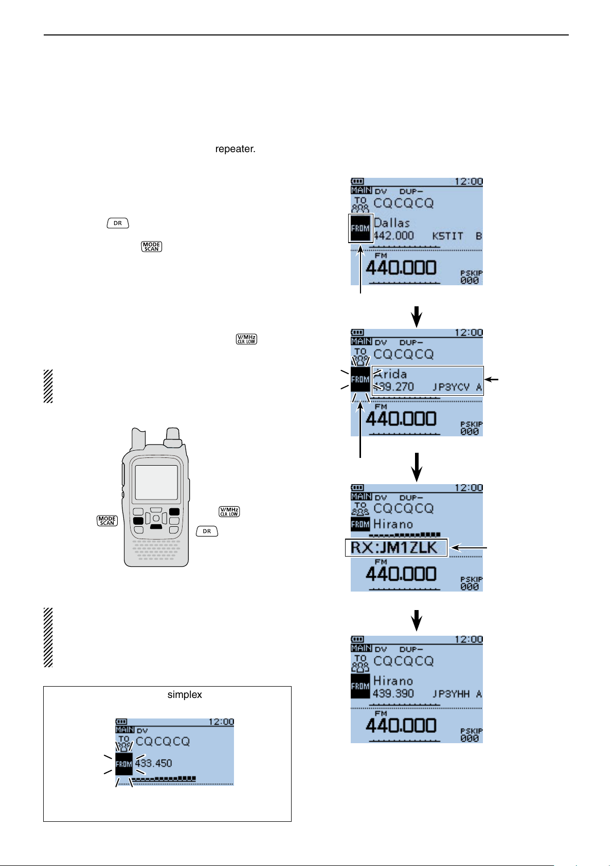
D-STAR OPERATION <BASIC>
Previous view
8
“FROM” (Access repeater) setting (Continued) ■
D Using the DR mode scan
The DR mode scan is useful to find a repeater.
To quickly find a repeater, the DR mode scan skips repeaters that are not specified as an access repeater.
(“USE (FROM)” setting is “NO” (SKIP is set) on the repeater list.)
Hold down q for 1 second.
• The DR mode is selected.
Hold down [SCAN] w
• The frequency decimal point and “FROM” blink while
scanning.
• The repeaters in the repeater list are sequentially displayed.
• The scan pauses when a signal is received. The scan
resumes the same as other scanning. (p. 16-18)
When the transceiver receives a signal from a re- e
peater, the scan stops, then push [CLR]
• The DR mode scan is cancelled.
to start the DR mode scan.
.
Example: Select the “Hirano repeater using the
DR mode scan.
“FROM” is selected.
You can skip certain repeaters from a scan target.
You can also skip all repeaters in certain groups from
a scan. See page 9-37 for details.
NOTE:
Even if the transceiver receives a signal from a repeater, the repeater may not receive the transceiver’s signal, because the repeater’s output power is
higher than the transceiver’s.
The repeaters
are sequentially
displayed.
While DR mode scanning
Blinks
Means “JM1ZLK” is
using the “Hirano”
repeater.
While receiving a signal from a repeater
The DR mode scan scans simplex frequencies if they
are entered in the repeater list.
Blinks
Completed
While receiving a
signal on 433.450.
8-4
Page 77

D-STAR OPERATION <BASIC>
D-pad
(�)
(Ent)
Previous view
8
“FROM” (Access repeater) setting (Continued) ■
D Using the Repeater Search function
The transceiver searches for the nearest repeater by
using your own and repeater’s position data.
Receiving your own position data from the GPS 1.
receiver
When it is difficult to receive signals indoors, even if
you are near a window, try going outdoors for better
reception.
Push [MENU] q .
Push D-pad( w ) to select the root item (“GPS”), and
then push D-pad(Ent) to go to the next level.
( MENU > GPS > GPS Set > GPS Select)
Refer to the menu sequence show directly above e
and push D-pad() to select, and then D-pad(Ent)
to enter, one or more times until the last screen is
displayed.
Push D-pad( r ) to select “Internal GPS.”
• The transceiver starts to receive your position data.
Push [MENU] t to save, and exit the MENU
screen.
• The GPS icon blinks when receiving data, as illustrated
below, and stops blinking when valid data is received.
➪ ➪ ➪
- If “Manual” was selected, the icon does not appear.
• It may take only a few seconds to receive, but depending on the environment, it may take a few minutes. If you
have difficulties receiving, we recommend that you try a
different location.
Example: Select the “Hirano” repeater that is
the top search result.
Appears
To display your position data:
q Push [QUICK] .
w Push D-pad() to select "GPS Position," and then
push D-pad(Ent).
• Your position is displayed on the GPS POSITION
e Push [CLR] to exit.
Continued on the next page.
screen.
8-5
Page 78

D-STAR OPERATION <BASIC>
D-pad
(�)
(Ent)
Previous view
8
“FROM” (Access repeater) setting ■
Using the Repeater Search function (Continued) D
Receiving your own position from the GPS re-2.
ceiver
Hold down q
• The DR mode is selected.
for 1 second.
Push D-pad( w ) to select “FROM,” and then push D-
pad(Ent).
Push D-pad( e ) to select “Near Repeater,” and then
push D-pad(Ent).
• The Repeater Search function starts.
• Up to 20 of the nearest repeaters are displayed.
Push D-pad( r ) to select “Hirano,” and then push D-
pad(Ent).
• “Hirano” is displayed in “FROM.”
“FROM” is selected.
NOTE: When the position data accuracy level is set
to “Approximate,” the direction data is not displayed if
the distance to the repeater is under 5 kilometers.
(p. 9-30)
NOTE:
When using the Repeater Search function, be sure to
first receive your own position data.
• If no repeater is found in a 160 kilometers range,
screen 1, as shown to the right, will be displayed.
• If the last received position can be used, screen 2, as
shown to the right, will be displayed.
Shows the distance
and direction from your
position to the repeater
Completed
Screen 1 Screen 2
Shows the call sign
of “Hirano430,”
8-6
Page 79

D-STAR OPERATION <BASIC>
D-pad
(�)
(Ent)
Previous view
8
“FROM” (Access repeater) setting (Continued) ■
D Using the TX History
The TX History stores up to 10 “FROM” (Access repeater) repeaters used when you transmit a call in the
DR mode.
NOTE: Only repeaters you transmitted to in the DR
mode are stored in the TX History.
Hold down q for 1 second.
• The DR mode is selected.
Push D-pad( w ) to select “FROM,” and then push D-
pad(Ent).
Push D-pad( e ) to select “TX History,” and then push
D-pad(Ent).
Push D-pad( r ) to select “Hirano,” and then push D-
pad(Ent).
• “Hirano” is displayed on “FROM.”
Example: Select the “Hirano” repeater from
the TX History.
“FROM” is selected.
You can display detailed repeater information on the
TX HISTORY screen, or delete it from there.
Push [QUICK] ➥ on the TX HISTORY screen,
then push D-pad() to select the desired item,
and then push D-pad(Ent).
Completed
8-7
Page 80
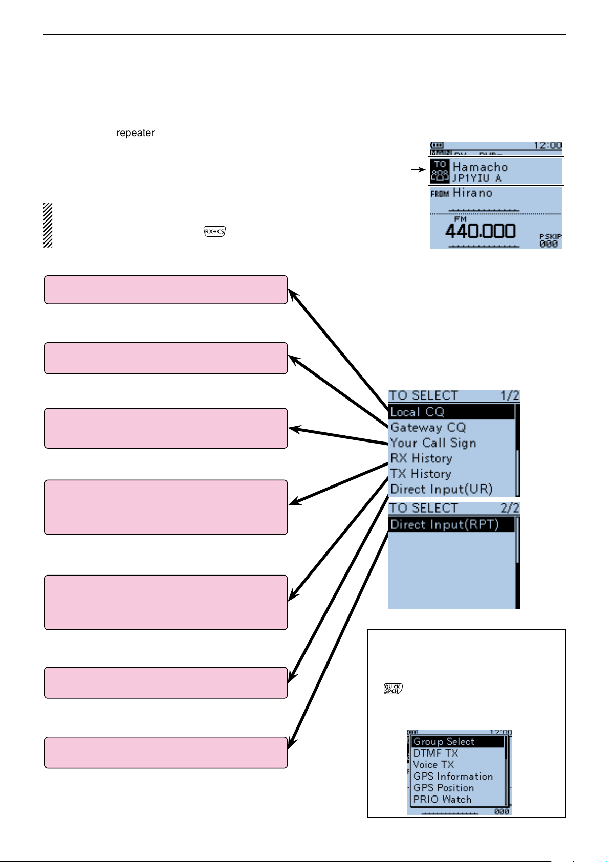
D-STAR OPERATION <BASIC>
Previous view
8
■ “TO” (Destination) setting
The destination repeater or station must be set to “TO”
when you transmit a call in the DV mode.
You have seven ways to set the destination.
Click the title as shown below to jump to the specified
page.
NOTE: After you receive the repeater’s signal, the
calling station’s call sign can be captured by holding
down the Call Sign Capture key ( ), and you can
quickly and easily reply to a received call.
To make a Local Area CQ call
1: “Local CQ” setting (p. 8-9)
Set “CQCQCQ” in “TO” (Destination).
To make a Gateway CQ call
2: “Gateway CQ” setting (p. 8-10)
Select a repeater from the repeater list.
“Hamacho” repeater
is set in “TO.”
[TO SELECT] screen
To make a call to a specific station
3: “Your Call Sign” setting (p. 8-11)
Select the station call sign in the Your Call Sign
memory.
When the destination data is stored in the RX History
4: Setting from the RX History (p. 8-12)
When you receive a call, the calling station data is
stored in the RX History.
You can select the destination from the record.
When the destination data is stored in the TX History
5: Setting from the TX History (p. 8-13)
When you transmit a call, the destination repeater or
station data is stored in the TX History.
You can select the destination from the record.
To directly input the destination station call sign
6: Direct Input (UR) (p. 8-14)
Directly input the destination station call sign.
To directly input the destination repeater call sign
7: Direct Input (RPT) (p. 8-15)
Directly input the destination repeater call sign.
How to switch the repeater group:
When “Local CQ” or “Gateway CQ” is selected, you can switch the repeater group.
While in the DR mode, push [QUICK] ➥
to open the Quick menu. Then
push D-pad() to select “Group Select.”
• You can switch the repeater group using
D-pad()
8-8
Page 81

D-STAR OPERATION <BASIC>
D-pad
(�)
(Ent)
Previous view
8
“TO” (Destination) setting (Continued) ■
D Using the “Local CQ” (Local Area call)
“CQCQCQ” is set in “TO” to call a station through your
local area (access) repeater.
q Hold down for 1 second.
• The DR mode is selected.
Push D-pad( w ) to select “TO” (Destination), and then
push D-pad(Ent).
Push D-pad( e ) to select “Local CQ,” and then push
D-pad(Ent).
• “CQCQCQ” is displayed on “TO.”
Example: Making a Local area call by accessing the
“Hirano” repeater.
Completed
8-9
Page 82
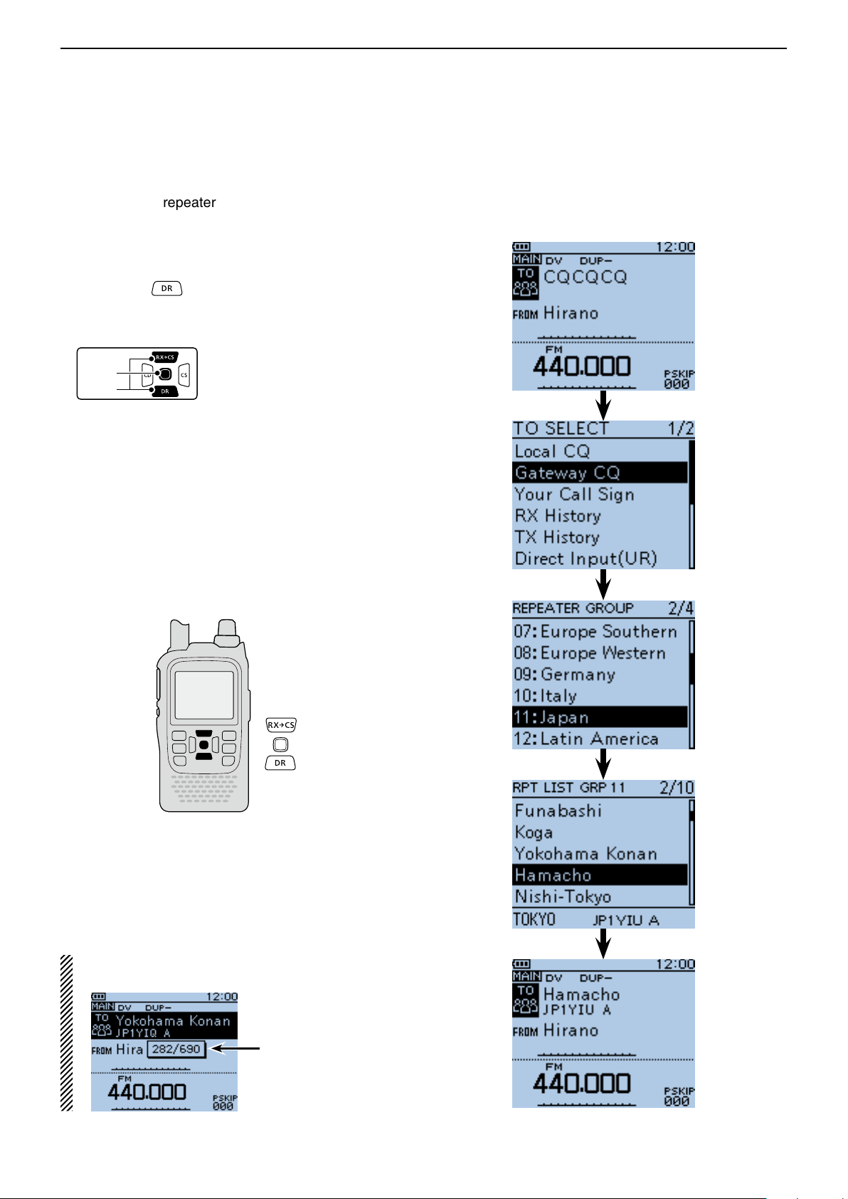
D-STAR OPERATION <BASIC>
D-pad
(�)
(Ent)
Previous view
8
“TO” (Destination) setting (Continued) ■
D Using the “Gateway CQ” (Gateway call)
The destination repeater is set in “TO” to call a station
through your local area (access) repeater, gateway
repeater, the internet and then to your destination repeater.
q Hold down for 1 second.
• The DR mode is selected.
Push D-pad( w ) to select “TO” (Destination), and then
push D-pad(Ent).
Push D-pad( e ) to select “Gateway CQ,” and then
push D-pad(Ent).
• The REPEATER GROUP screen is displayed.
Push D-pad( r ) to select the repeater group where
your destination repeater is listed, and then push Dpad(Ent).
• Example: “11: Japan”
Push D-pad( t ) to select the destination repeater,
and then push D-pad(Ent).
• Example: “Hamacho”
• “Hamacho” is displayed on “TO.”
Example: Making a gateway CQ call to (Japan; Hama-
cho) from the “Hirano” repeater.
After selecting a repeater, you can select other repeater preset in your transceiver by rotating [DIAL].
Means this repeater is programmed
as the 282th of the
690 repeaters on
the repeater list.
Completed
8-10
Page 83
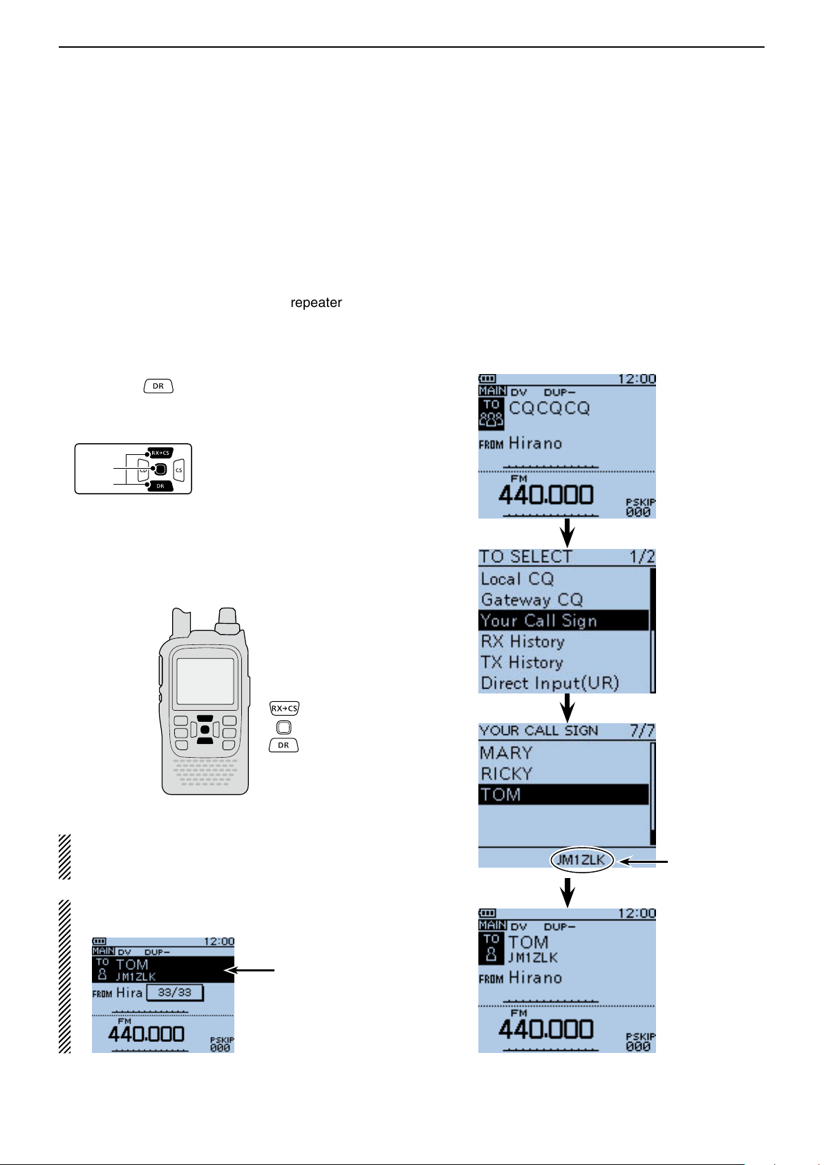
D-STAR OPERATION <BASIC>
D-pad
(�)
(Ent)
Previous view
8
“TO” (Destination) setting (Continued) ■
D Using the “Your Call Sign”
The “Your Call Sign” memory stores the programmed
“UR” (destination) call sign.
When you select an individual station call sign for the
“TO” (Destination) setting using “Your Call Sign,” a gateway call can be made.
When you call the destination through a gateway, the
signal is automatically sent to the last repeater that the
station accessed.
So, even if you don't know where the station is, you can
make a call.
Hold down q for 1 second.
• The DR mode is selected.
Push D-pad( w ) to select “TO,” and then push D-
pad(Ent).
Example: Select “TOM” from the “Your Call Sign.”
Push D-pad( e ) to select “Your Call Sign,” and then
push D-pad(Ent).
Push D-pad( r ) to select the destination, and then
push D-pad(Ent).
• Example: “TOM”
• “TOM” is displayed on “TO.”
NOTE: If the repeater, set to “FROM” (Access Repeater) has no Gateway call sign, you cannot make
a gateway call.
After selecting a destination, you can select other
station preset in your transceiver by rotating [DIAL].
The call sign of
the selected station is displayed.
Means this station
is programmed as
the 33th of the 33
stations on your
memory.
Completed
8-11
Page 84
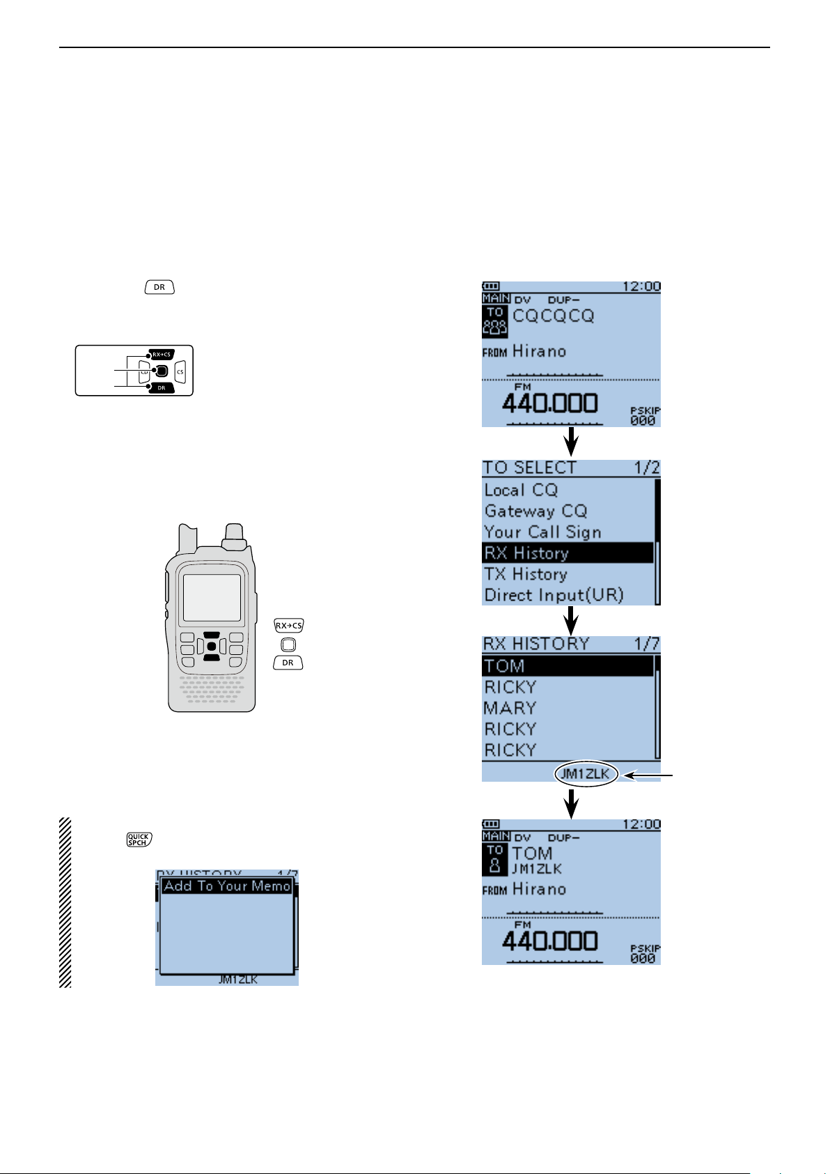
D-STAR OPERATION <BASIC>
D-pad
(�)
(Ent)
Previous view
8
“TO” (Destination) setting (Continued) ■
D Using the RX History
When a call is received in the DV mode, the call data is
stored in the RX History.
Up to 50 Callers, and only the last Called call signs can
be stored.
Hold down q for 1 second.
• The DR mode is selected.
Push D-pad( w ) to select “TO,” and then push D-
pad(Ent).
Push D-pad( e ) to select “RX History,” and then push
D-pad(Ent).
Push D-pad( r ) to select the destination, and then
push D-pad(Ent).
• Example: “TOM”
• “TOM” is displayed on “TO.”
Example: Select “TOM” from RX History.
To add the RX HISTORY data to memory, push
[QUICK] on the RX HISTORY screen, then push
D-pad(Ent).
The call sign of
the selected station is displayed.
Completed
8-12
Page 85
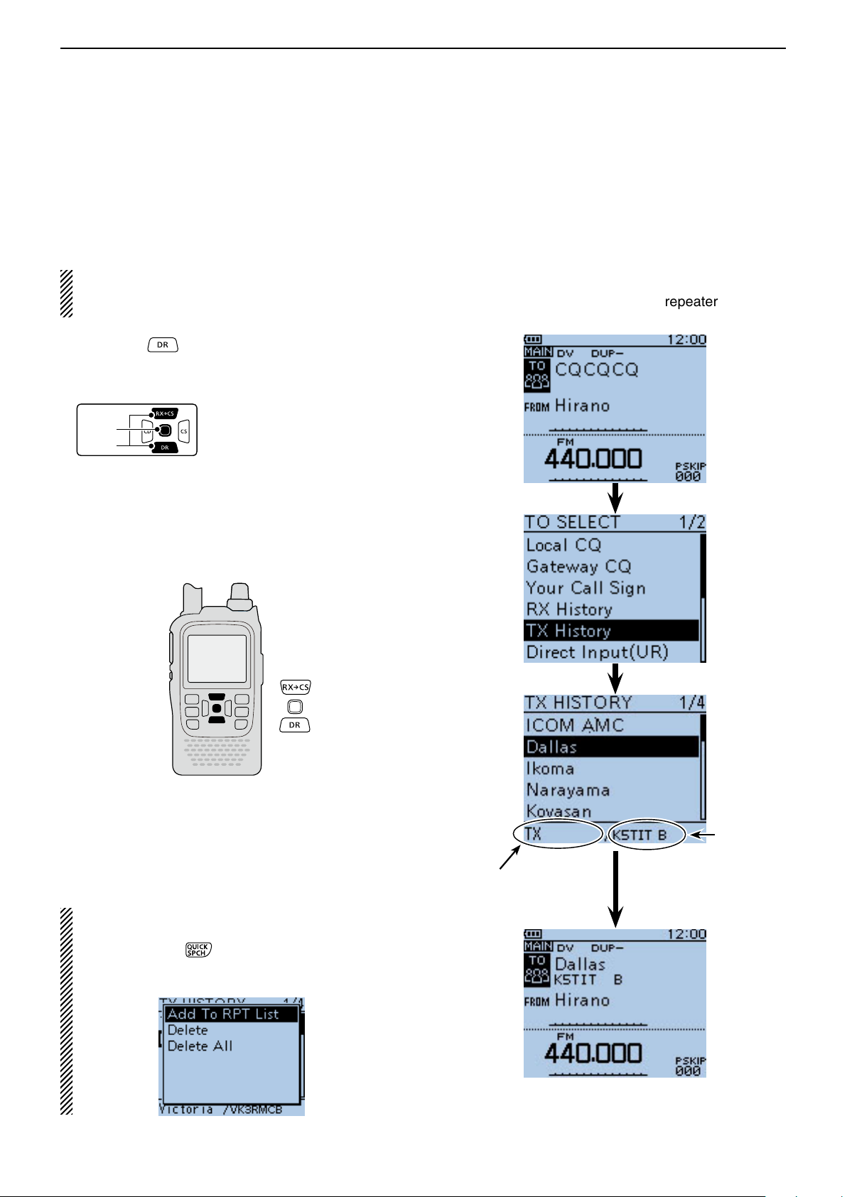
D-STAR OPERATION <BASIC>
D-pad
(�)
(Ent)
Previous view
8
“TO” (Destination) setting (Continued) ■
D Using the TX History
The TX History stores the name and/or call sign of up
to 20 “TO” (Destination) settings which were used when
you made the calls.
NOTE: If you never transmit a call in the DV mode,
you cannot select “TO” (destination) from the TX History.
Hold down q for 1 second.
• The DR mode is selected.
Push D-pad( w ) to select “TO,” and then push D-
pad(Ent).
Push D-pad( e ) to select “TX History,” and then push
D-pad(Ent).
Push D-pad( r ) to select the destination, and then
push D-pad(Ent).
• Example: “Dallas”
• “Dallas” is displayed on “TO.”
Example: Select the “Melbourne” repeater in the TX
History.
You can add the TX HISTORY data to memory, or
delete it from there.
Push [QUICK] ➥ on the TX HISTORY screen,
then push D-pad() to select the desired item,
and then push D-pad(Ent).
The Sub name is displayed when a repeater is selected.
8-13
“Dallas”
repeater’s
call sign is
displayed.
Completed
Page 86
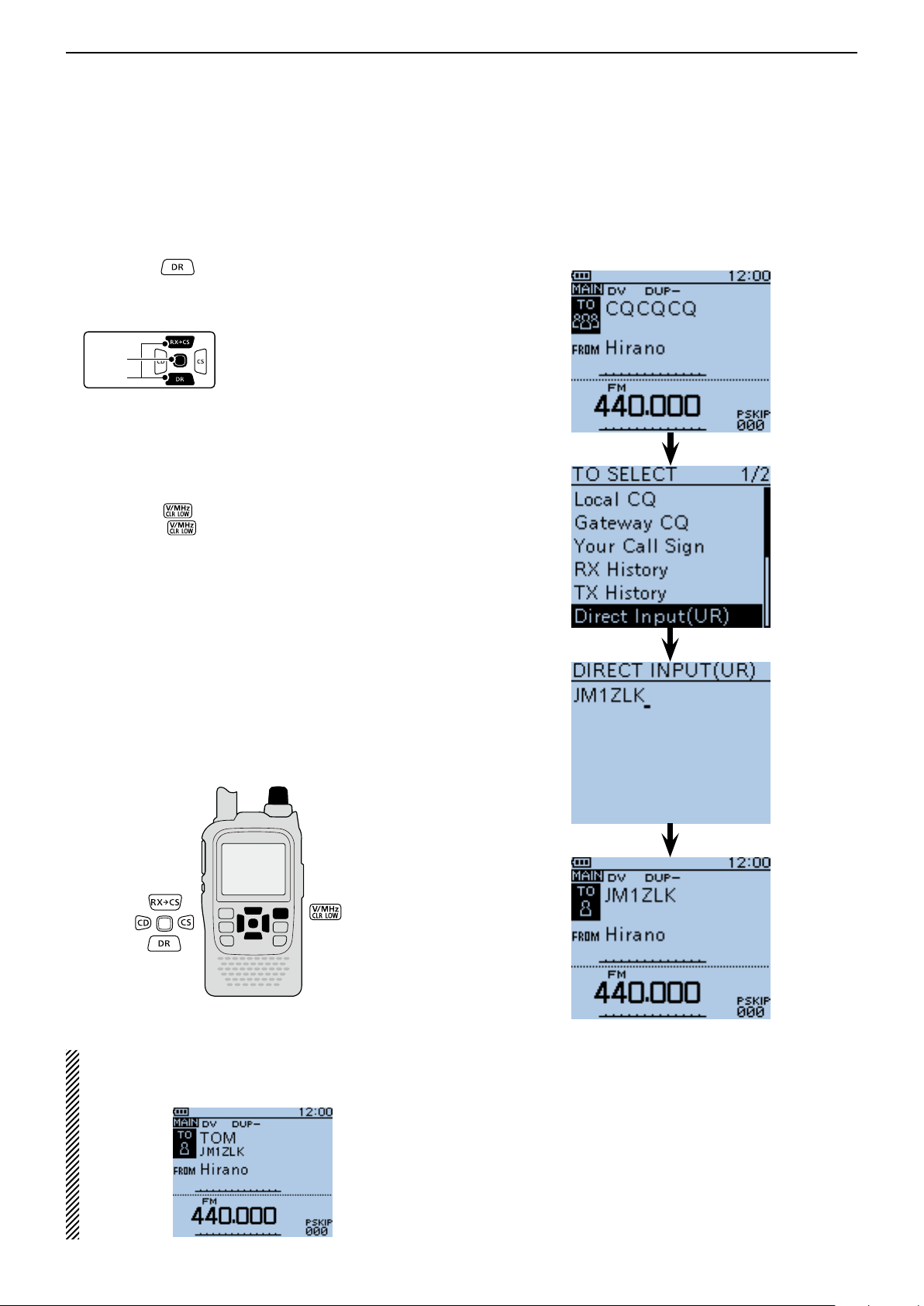
D-STAR OPERATION <BASIC>
D-pad
(�)
(Ent)
Previous view
8
“TO” (Destination) setting (Continued) ■
D Directly inputting (UR)
The destination station call sign can be directly input.
Hold down q for 1 second.
• The DR mode is selected.
Push D-pad( w ) to select “TO,” and then push D-
pad(Ent).
Push D-pad( e ) to select “Direct Input (UR).”
Push D-pad(Ent) to enter the edit mode. r
Rotate [DIAL] to select a desired character. t
(Example: J)
• A to Z, 0 to 9, / and a space can be selected.
• Rotate [DIAL] counter clockwise to enter a space.
• Push [CLR]
down [CLR]
first to the right, and then to the left of the cursor.
Push D-pad( y ) to move the cursor to the second
digit.
Repeat steps u t and y to enter a call sign of up to 8
characters, including spaces.
(Example: First, J, then M, then 1, then Z, then L,
After entering, push D-pad(Ent) twice to program. i
• “JM1ZLK” is displayed on “TO.”
• After programming, you can correct the call sign in the
DIRECT INPUT (UR) screen.
• The programmed call sign remains on the DIRECT INPUT (UR) screen, until inputting a new call sign.
to delete the selected character, or hold
to continuously erase the characters,
then K.)
Example: Directly input the call sign “JM1ZLK.”
[DIAL]
If the programmed call sign is duplicated in “Your
Call Sign” memory, the name is displayed. (Only
when the name has been programmed.)
Completed
8-14
Page 87
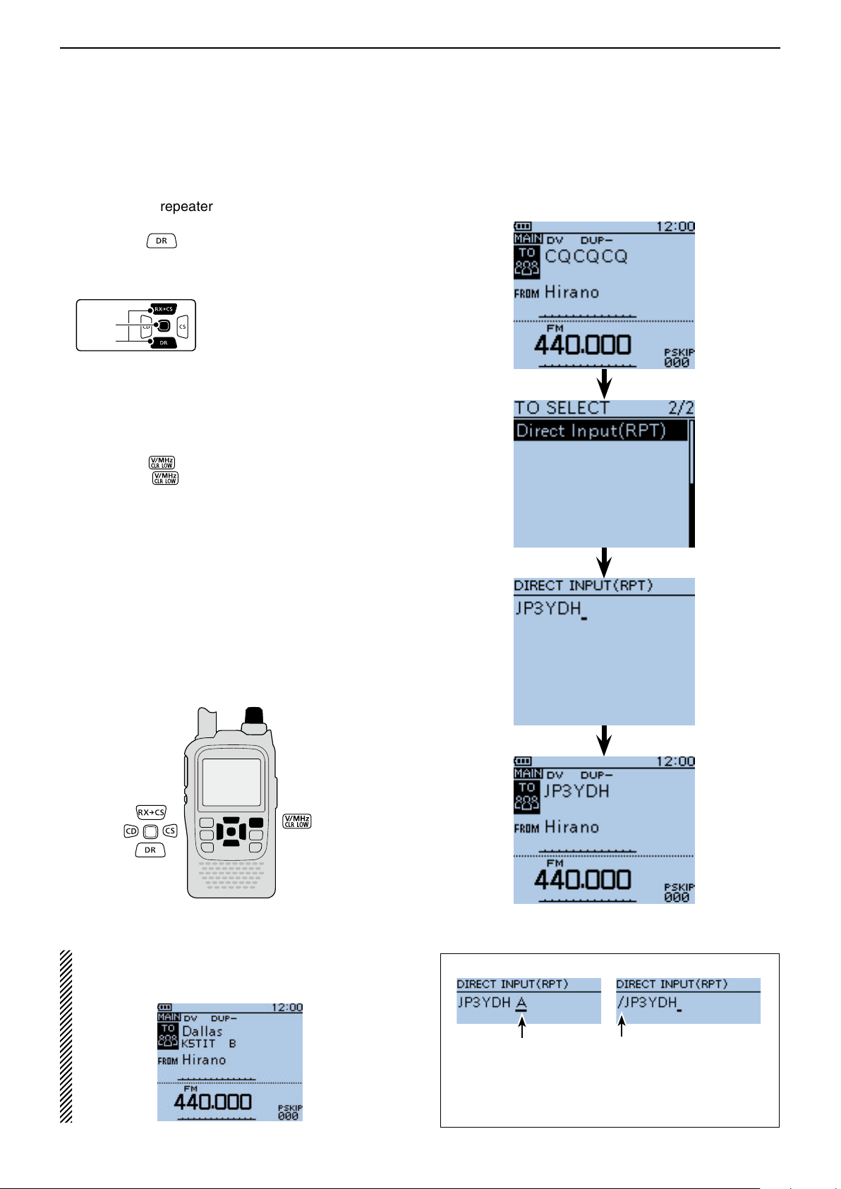
D-STAR OPERATION <BASIC>
D-pad
(�)
(Ent)
Previous view
8
“TO” (Destination) setting (Continued) ■
D Directly inputting (RPT)
The destination repeater call sign can be directly input.
Hold down q for 1 second.
• The DR mode is selected.
Push D-pad( w ) to select “TO,” and then push D-
pad(Ent).
Push D-pad( e ) to select “Direct Input (RPT).”
Push D-pad(Ent) to enter the edit mode. r
Rotate [DIAL] to select a desired character. t
(Example: J)
• A to Z, 0 to 9, / and a space can be selected.
• Rotate [DIAL] counter clockwise to enter a space.
• Push [CLR]
down [CLR]
first to the right, and then to the left of the cursor.
Push D-pad( y ) to move the cursor to the second
digit.
Repeat steps u t and y to enter a name of up to 8
characters, including spaces.
(Example: First, J, then P, then 3, then Y, then D,
After entering, push D-pad(Ent) twice. i
• “JP3YDH” is displayed on “TO.”
• After programming, you can correct the call sign in the
DIRECT INPUT (RPT) screen.
• The programmed call sign remains on the DIRECT INPUT (RPT) screen, until inputting a new call sign.
to delete the selected character, or hold
to continuously erase the characters,
then H.)
Example: Directly input the call sign “JP3YDH”
[DIAL]
If the programmed call sign is duplicated to the repeater list, the name is displayed. (Only when the
name has been programmed.)
Completed
The following settings are also correct.
The repeater node*
is input.
* Although the repeater node letter is ‘B’ for 430 MHz band,
‘A’ is used in Japan. See page 8-1 for details.
“/” is input.
In this case, the call sign is of
a repeater for a Gateway call.
8-15
Page 88

Section 9
Previous view
IMPORTANT!
• The repeater list, described in this
manual, may differ from your transceiver’s preloaded contents.
• Although Japanese repeaters are
used in the setting examples, the
Japanese repeater node (port) letters are different from other country’s.
Be sure to add a repeater node letter
as the 8th digit in the call sign field
after a repeater call sign, according
to the repeater frequency band, as
shown below.
1200 MHz : A (B in Japan)
430 MHz : B (A in Japan)
144 MHz : C (no D-STAR repeat-
ers in Japan)
D-STAR OPERATION <ADVANCED>
Message operation ■ .............................................. 9-2
TX message programming D .............................. 9-2
Message Transmission D .................................... 9-3
TX message deleting D ....................................... 9-4
Received call sign viewing ■ ................................... 9-5
View in the RX History screen D ......................... 9-5
BK mode communication ■ ..................................... 9-7
EMR communication ■ ........................................... 9-8
Adjusting the EMR AF level D ............................. 9-9
Display type setting ■ ............................................. 9-9
DV automatic detection ■ ...................................... 9-10
Automatic Reply function ■ ................................... 9-11
Recording an Auto Reply voice announcement D
Playing back the recorded voice audio D .......... 9-12
Auto Position Reply function D .......................... 9-13
Low-speed data communication ■ ........................ 9-14
Connection D .................................................... 9-14
Low-speed data communication application setting D
Low-speed data communication operation D .... 9-14
Speech function ■ ................................................. 9-15
To announce the received call sign D ............... 9-15
To announce the RX>CS call sign D ................. 9-16
Speech Language selection D .......................... 9-17
Phonetic Code setting for the Speech alphabet D
character ....................................................... 9-17
Speech speed selection D ................................ 9-18
Speech level selection D ................................... 9-18
Digital squelch functions ■ .................................... 9-19
The digital call sign squelch setting D ............... 9-19
Pocket beep function with the digital call sign D
squelch .......................................................... 9-19
The digital code squelch setting D .................... 9-20
D
Pocket beep function with the digital code squelch
Viewing the call signs ■ ........................................ 9-21
Repeater list ■ ...................................................... 9-22
Repeater list contents D .................................... 9-22
Repeater list programming ■ ................................ 9-23
New repeater programming D ........................... 9-23
D
Required items for the communication cases
Editing a repeater list ■ ......................................... 9-32
Deleting a repeater list ■ ...................................... 9-33
Rearrange the display order of the repeater ■ ...... 9-34
Adding the Repeater information ■ using the
RX History ......................................................... 9-35
Skip setting for the DR mode scan ■ .................... 9-36
Individual skip setting D .................................... 9-36
Group skip setting D ......................................... 9-37
Repeater group name programming ■ ................. 9-38
Repeater detail screen ■ ...................................... 9-39
Your (destination) call sign programming ■ .......... 9-40
Deleting Your (destination) call sign ■ ................... 9-42
Rearrange the display order of Your (destination) ■
call sign ............................................................. 9-43
About the repeater list default values ■ ................ 9-44
Opening the default repeater list D ................... 9-44
Your setting is correct? ■ ...................................... 9-45
. 9-12
. 9-14
. 9-20
. 9-23
9-1
Page 89

D-STAR OPERATION <ADVANCED>
D-pad
(�)
(Ent)
Previous view
9
■ Message operation
The transceiver has a total of 5 message memories to
store short messages to transmit during DV mode operation.
TX messages of up to 20 characters can be programmed in each of the 5 message memories.
TX message programming D
Push [MENU] q .
Push D-pad( w ) to select the root item (“My Station”),
and then push D-pad(Ent).
Push D-pad( e ) to select “TX Message,” and then
push D-pad(Ent).
Push D-pad( r ) to select message memory number
“1.”
Push [QUICK] t .
Push D-pad( y ) to select “Edit.”
Push D-pad(Ent) to enter the TX message edit u
mode.
Rotate [DIAL] to select a desired character. i
(Example: J)
• Selectable input characters are Upper case letters, Low-
er case letters, Numbers or Symbols.
• The selected character blinks.
• Push D-pad() to move the cursor backward or forward.
• While selecting a character, push [QUICK]
the character to an upper case or lower case letter.
• While selecting a digit, push [QUICK]
input mode selection window.
• A space can be selected, in any input mode selected.
• Rotate [DIAL] counter clockwise to enter a space.
• Push [CLR]
down [CLR]
first to the right, and then to the left of the cursor.
• See page 2-7 for programming details.
to delete the selected character, or hold
to continuously delete the characters,
Push D-pad( o ) to move the cursor to the second
digit.
!0 Repeat steps i and o to enter up to 20 characters,
including spaces.
(Example: First, J, then A, then P, then A, then N,
then (space), then >, then T, then O,
then M.)
!1 After entering the message, push D-pad(Ent) two
times to program.
!2 Push [MENU] to exit the MENU screen.
to change
to open the
Example: To program “JAPAN >TOM” into message
memory number 1.
“JAPAN” and a
Character type
selection screen
space are entered.
Symbol type
is selected
To input “>,”
[>] is selected
in the symbol
list screen.
“JAPAN >TOM”
is entered.
9-2
Page 90
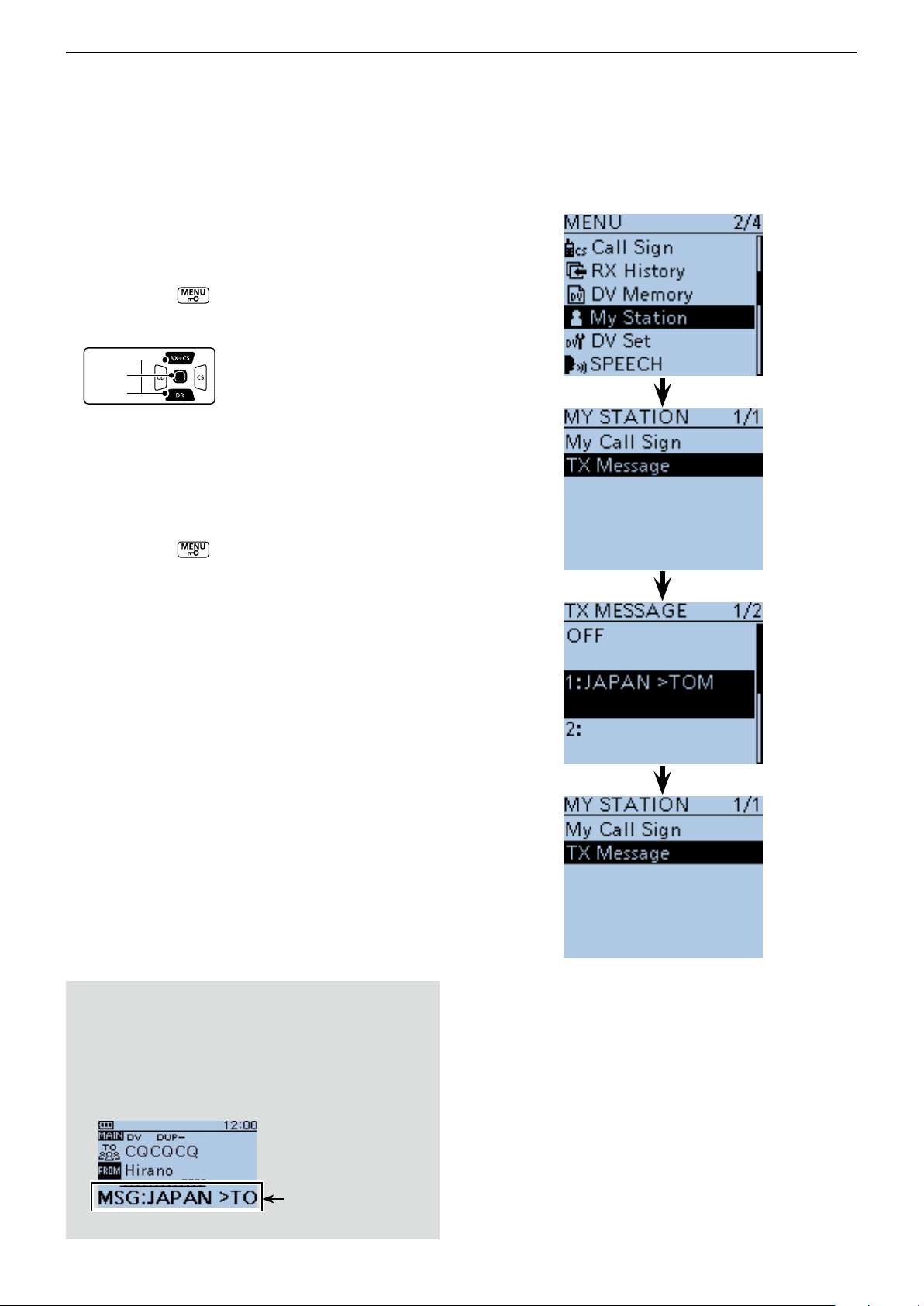
D-STAR OPERATION <ADVANCED>
D-pad
(�)
(Ent)
Previous view
9
Message operation (Continued) ■
D Message Transmission
You can transmit a preprogrammed text message by
pushing [PTT]. First, select a TX message which also
turns ON the message transmission function.
Push [MENU] q .
Push D-pad( w ) to select the root item (“My Station”),
and then push D-pad(Ent).
Push D-pad( e ) to select “TX Message,” and then
push D-pad(Ent).
Push D-pad( r ) to select message memory number
1 to 5.
• To turn OFF the message transmission function, select
“OFF.”
t After selecting, push D-pad(Ent).
Push [MENU] y to exit the MENU screen.
• The message is transmitted along with your voice signal.
• The message is transmitted each time you push [PTT].
• The message is automatically transmitted every 30 sec-
onds during continuous transmission.
RX message display function
As the default, the received message is automatically
displayed and scrolled on the LCD.
To not display and scroll the received message, turn
OFF the RX message display function in “RX Message” of the MENU screen. (p. 16-74)
(MENU > Display > RX Message)
The received message is displayed
and scrolled here.
9-3
Page 91

D-STAR OPERATION <ADVANCED>
D-pad
(�)
(Ent)
Previous view
9
Message operation (Continued) ■
D TX message deleting
The programmed TX message can be deleted, as described below.
Push [MENU] q .
Push D-pad( w ) to select the root item (“My Station”),
and then push D-pad(Ent).
Push D-pad( e ) to select “TX Message,” and then
push D-pad(Ent).
Push D-pad( r ) to select message memory number
1.
Push [QUICK] t .
Push D-pad( y ) to select “Clear,” and then push D-
pad(Ent).
Push D-pad( u ) to select “YES,” and then push D-
pad(Ent).
Push [MENU] i to exit the MENU screen.
Example: To delete the programmed TX message “JA-
PAN >TOM” from message memory number
1.
9-4
Page 92
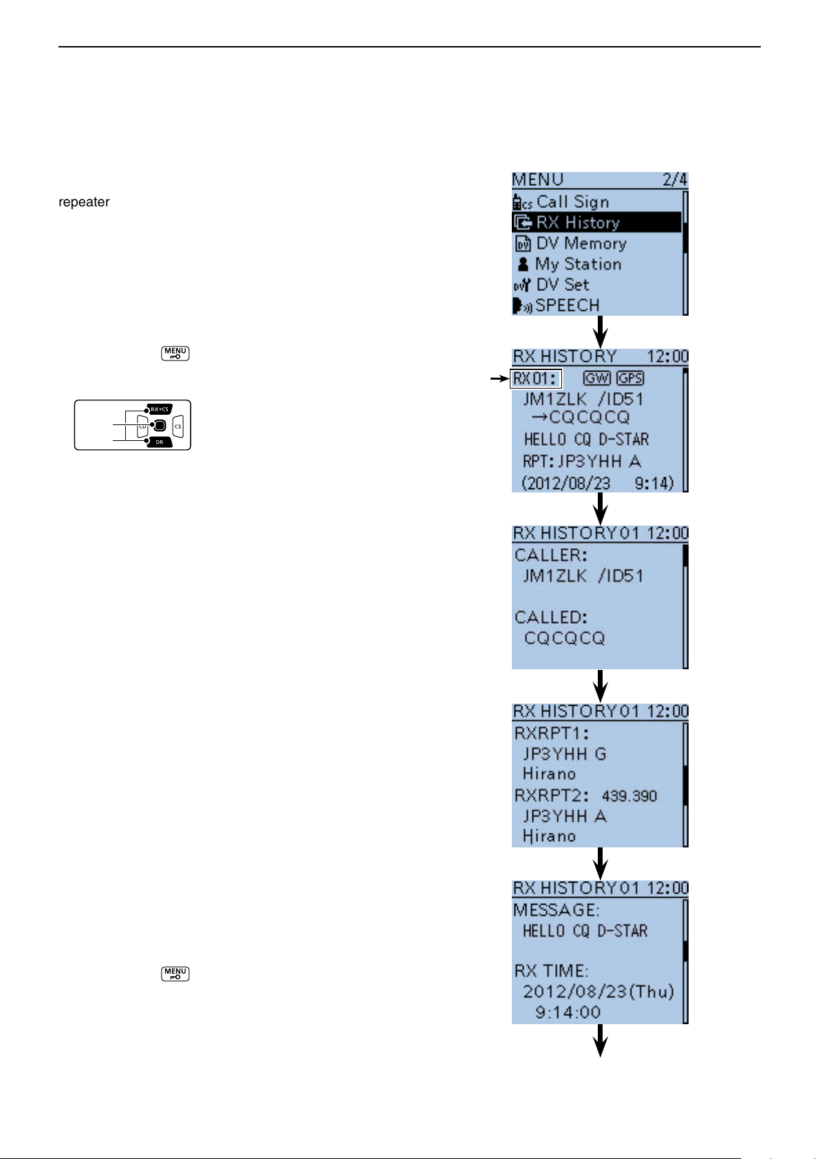
D-STAR OPERATION <ADVANCED>
D-pad
(�)
(Ent)
Previous view
9
■ Received call sign viewing
When a DV call is received, the calling station and the
repeater’s call signs are stored in the RX HISTORY
screen.
Up to 50 calls can be stored.
Even if the transceiver is turned OFF, the RX record
won’t be deleted.
The stored call signs can be displayed in the following
manner.
D View in the RX History screen
Push [MENU] q .
Push D-pad( w ) to select the root item (“RX History”),
and then push D-pad(Ent).
Push D-pad( e ) to select an RX history number be-
tween “RX01” and “RX50.”
• In addition to the RX history number, the call signs of
the caller and called station, RX message, Repeater call
sign of the called station, received date and time are displayed on the LCD.
• If only one call is received, skip step e.
• “GW” appears when the gateway call is received.
• “GPS” appears when the received call includes GPS po-
sition.
• “UP” appears when the repeater uplink signal is received.
Push D-pad(Ent) to show the contents of the RX his- r
tory.
Push D-pad( t ) to switch the displayed contents of
the RX history.
• CALLER : Shows the call sign of the caller station and
any note programmed after the call sign.
• CALLED : Shows the call sign of the called station.
• RXRPT1* : Shows the call sign of the repeater that was
accessed by the caller station. If it was a
call through a gateway and the internet, this
item displays the gateway repeater call sign
of your local area repeater.
• Rx RPT2* : Shows the call sign of the repeater you re-
ceived the call from.
• MESSAGE : Shows any message included in the re-
ceived call, if programmed.
• RX TIME : Shows the date and time the call was re-
ceived.
* “FREQUENCY” appears instead of these items when the
call was not through a repeater (Simplex call), to show the
frequency that was used.
Push [MENU] y to exit the MENU screen.
RX history
number
When the received call includes the GPS
position data, it is displayed after RX TIME.
9-5
Page 93

D-STAR OPERATION <ADVANCED>
JG3LUK listening
on JP3YHH port
A...
JG3LUK listening
on JP3YHH port
A...
JG3LUK listening
on JP3YHH port
A...
JM1ZLK calling
to JP1YIU port
A...
JM1ZLK calling
to JP1YIU port
A...
JM1ZLK calling
to JP1YIU port
A...
INTERNETINTERNET
Previous view
9
Received call sign viewing (Continued) ■
You can delete the RX HISTORY data.
Push [QUICK] ➥ on the RX HISTORY or the
contents screen, then push D-pad() to select
“Delete” or “Delete All.” And then push D-pad(Ent)
to delete.
When the received call includes
GPS position data.
Information ✓
“RX RPT1” setting may be differ, depending on the
communication form.
Example: When a Local area call is received.
RXRPT1RXRPT2
CALLED
CALLER
YOUR STATION
Example: When a Gateway call is recelved.
RXRPT2
GW
RXRPT1
CALLED
YOUR STATION
CALLER
9-6
Page 94
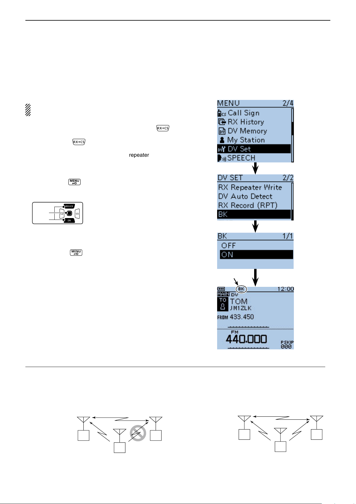
D-STAR OPERATION <ADVANCED>
D-pad
(�)
(Ent)
Previous view
9
■ BK mode communication
The BK (Break-in) function allows you to break into a
conversation, where the two other stations are communicating with call sign squelch enabled. (Default: OFF)
NOTE: The BK function is automatically turned OFF
when transceiver is turned OFF.
After receiving a DV conversation, hold down q
for 1 second.
• After releasing , beeps sound, and the calling station call sign is announced. (RX>CS Speech function)
• The calling station or call sign of the repeater used is
automatically set.
• When a call sign is not received correctly, error beeps
sound, and no call sign is set.
Push [MENU] w .
Push D-pad( e ) to select the root item (“DV Set”),
and then push D-pad(Ent).
Push D-pad( r ) to select “BK,” and then push D-
pad(Ent).
Push D-pad( t ) to select “ON.”
Push [MENU] y to exit the MENU screen.
• “BK” appears.
When both stations are in standby, push [PTT] to u
transmit.
• The TX/RX indicator lights red.
• “BK” blinks on the station that receives the break-in call.
Appears
Release [PTT] to receive. i
Wait for a reply call from the station.
After receiving the reply call, communicate normally. o
!0 To cancel the BK mode, select “OFF” in “BK,” as step
t, or turn OFF the power.
How to use Break-in?
While using digital call sign squelch, the squelch never opens (no audio is heard) even if a call is received, unless
your own call sign is specified.
However, when a call including the “BK ON” signal (break-in call) is received, the squelch will open and audio is
heard even if the call is specified for another station.
• Station C calling to Station A with “BK OFF”
Station A and
B are communicating using digital call
sign squelch.
Station A Station B
Station C
Station B never hears that Station C
is calling Station A.
• Station C calling to Station A with “BK ON”
Station A and
B are communicating using
the digital call
sign squelch.
9-7
Station A Station B
Station C
Station B also hears that Station C
is calling Station A.
Page 95

D-STAR OPERATION <ADVANCED>
D-pad
(�)
(Ent)
Previous view
9
■ EMR communication
The EMR (Enhanced Monitor Request) communication
mode can be used in only the DV mode. In the EMR
mode, no call sign setting is necessary.
All transceivers that receive an EMR mode signal automatically open their squelch to receive the signal.
When an EMR mode signal is received, the audio (voice)
will be heard at the specified level, even if the volume
setting level is set to the minimum level, or digital call
sign/digital code squelch is in use. (Default: OFF)
NOTE: The EMR communication function is automatically turned OFF when the transceiver is turned
OFF.
Hold down q for 1 second.
• The DR mode is selected.
Push D-pad( w ) to select “FROM,” and then push D-
pad(Ent).
Example: To transmit from the “Hamacho” repeater in
the EMR mode
Push D-pad( e ) to select “Repeater List,” and then
push D-pad(Ent).
Push D-pad( r ) to select “11: Japan,” and then push
D-pad(Ent).
Push D-pad( t ) to select “Hamacho,” and then push
D-pad(Ent).
• “Hamacho” is displayed on “FROM”.
Push [MENU] y .
Push D-pad( u ) to select the root item (“DV Set”),
and then push D-pad(Ent).
Push D-pad( i ) to select “EMR,” and then push D-
pad(Ent).
Push D-pad( o ) to select “ON.”
!0 Push [MENU] to exit the MENU screen.
• “EMR” appears.
!1 Push [PTT] to transmit.
• The TX/RX indicator lights red.
• “EMR” blinks on a station that receives the EMR signal.
And the audio (voice) will be heard at the specified level,
or the [VOL] control level, whichever is higher.
!2 Release [PTT] to receive.
!3 To cancel the EMR mode, select “OFF” in step o, as
described above, or turn OFF the power.
Appears
9-8
Page 96
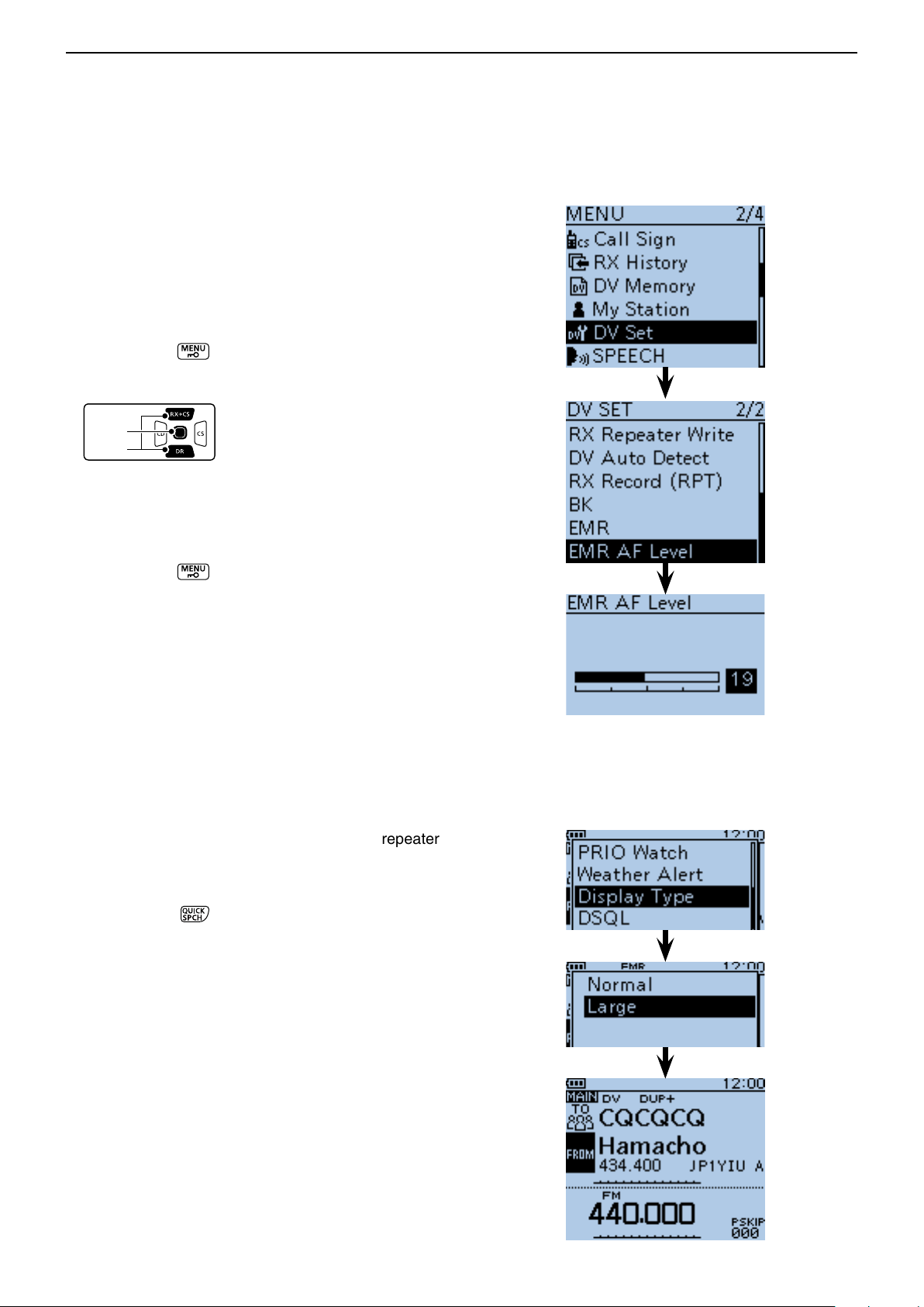
D-STAR OPERATION <ADVANCED>
D-pad
(�)
(Ent)
Previous view
9
EMR communication (Continued) ■
D Adjusting the EMR AF level
The audio output level when an EMR signal is received
is adjustable between 0 and 39.
When an EMR signal is received, the audio will be
heard at the preset level, or the [VOL] control level,
whichever is higher.
To disable the setting, set it to “0.”
Push [MENU] q .
Push D-pad( w ) to select the root item (“DV Set”),
and then push D-pad(Ent).
Push D-pad( e ) to select “EMR AF Level,” and then
push D-pad(Ent).
Push D-pad( r ) to adjust the EMR audio output level
between 0 (minimum) and 39 (maximum) in single
digit steps. (Default: 19)
Push [MENU] t to exit the MENU screen.
■ Display type setting
The display size in the DR mode, such as a repeater
name, call sign, and so on, can be set to Large.
Push [QUICK] q .
Push D-pad( w ) to select “Display Type,” and then
push D-pad(Ent).
Push D-pad( e ) to select “Large,” and then push D-
pad(Ent).
• The display size changes to large such as the repeater
(Default: Normal)
name set in “TO” and “FROM.”
9-9
Page 97
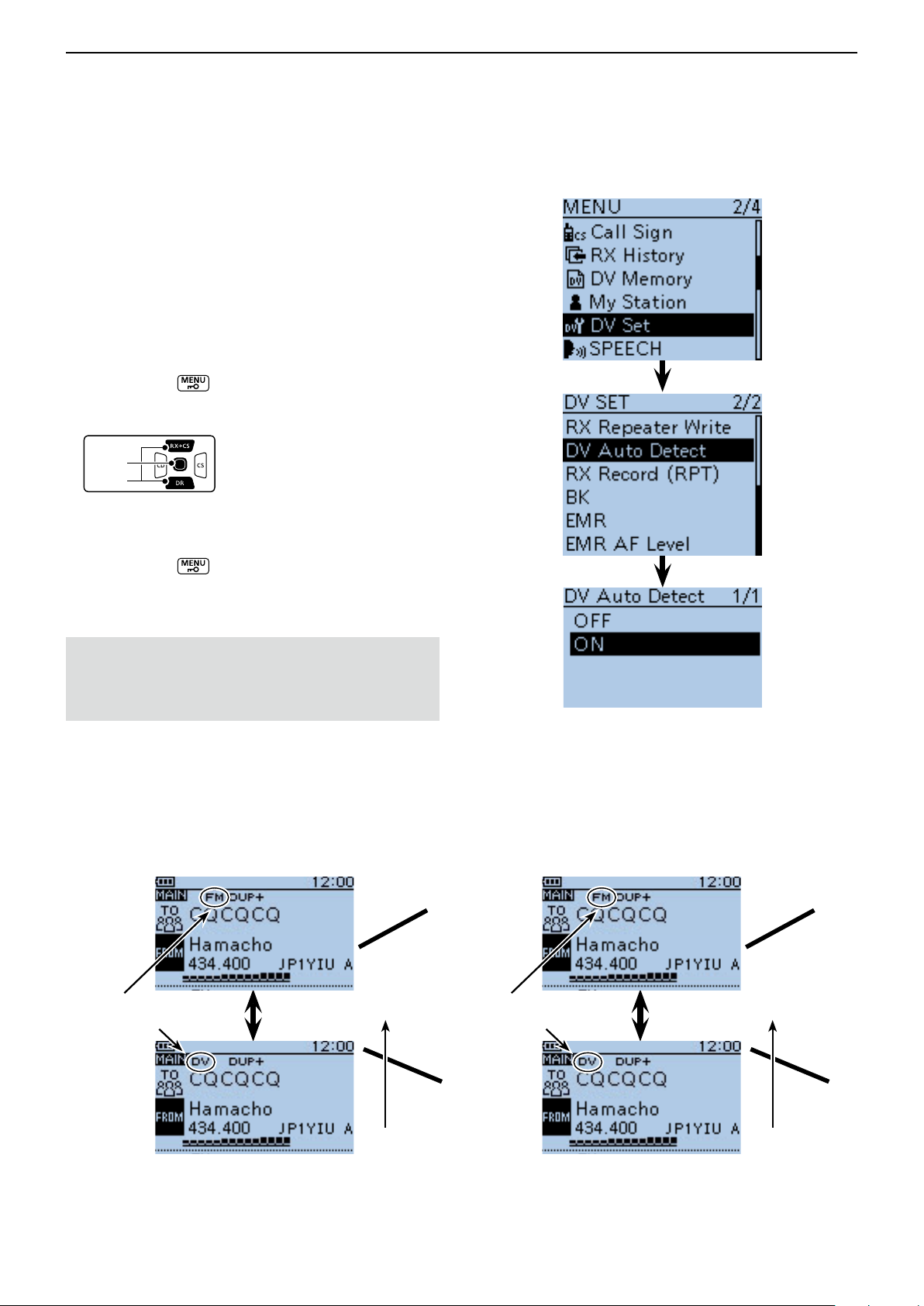
D-STAR OPERATION <ADVANCED>
D-pad
(�)
(Ent)
Previous view
9
■ DV automatic detection
If you receive an FM signal during DV mode operation,
the “DV” and “FM” icons alternately blink to indicate the
received signal is FM.
When the DV Auto Detect function is turned ON, the
transceiver automatically selects the FM mode to temporarily monitor the signal. (Default: OFF)
• Regardless of this setting, the “DV” and “FM” icons alter-
nately blink if you receive an FM signal during DV mode
operation.
Push [MENU] q .
Push D-pad( w ) to select the root item (“DV Set”),
and then push D-pad(Ent).
Push D-pad( e ) to select “DV Auto Detect,” and then
push D-pad(Ent).
Push D-pad( r ) to select “ON.”
Push [MENU] t to exit the MENU screen.
• When an FM signal is received in the DV mode, the “DV”
and “FM” icons sequentially blink, and the transceiver receives the signal in the FM mode.
When digital call sign squelch (DSQL) or digital code
squelch (CSQL) is selected, the transceiver does not
receive FM signals, even if this function is ON.
You can silently wait for calls from others.
<When an FM signal is received while in the DV mode>
• DV Auto Detect function: OFF
The “DV” and “FM” icons sequentially blink, but the audio cannot be heard.
These icons alternately blink
• • •
• DV Auto Detect function: ON
The “DV” and “FM” icons sequentially blink, and the audio can be heard.
Thanks for the
These icons alternately blink
nice QSO• • •
The audio cannot
be heard.
9-10
The audio can
be heard.
Page 98
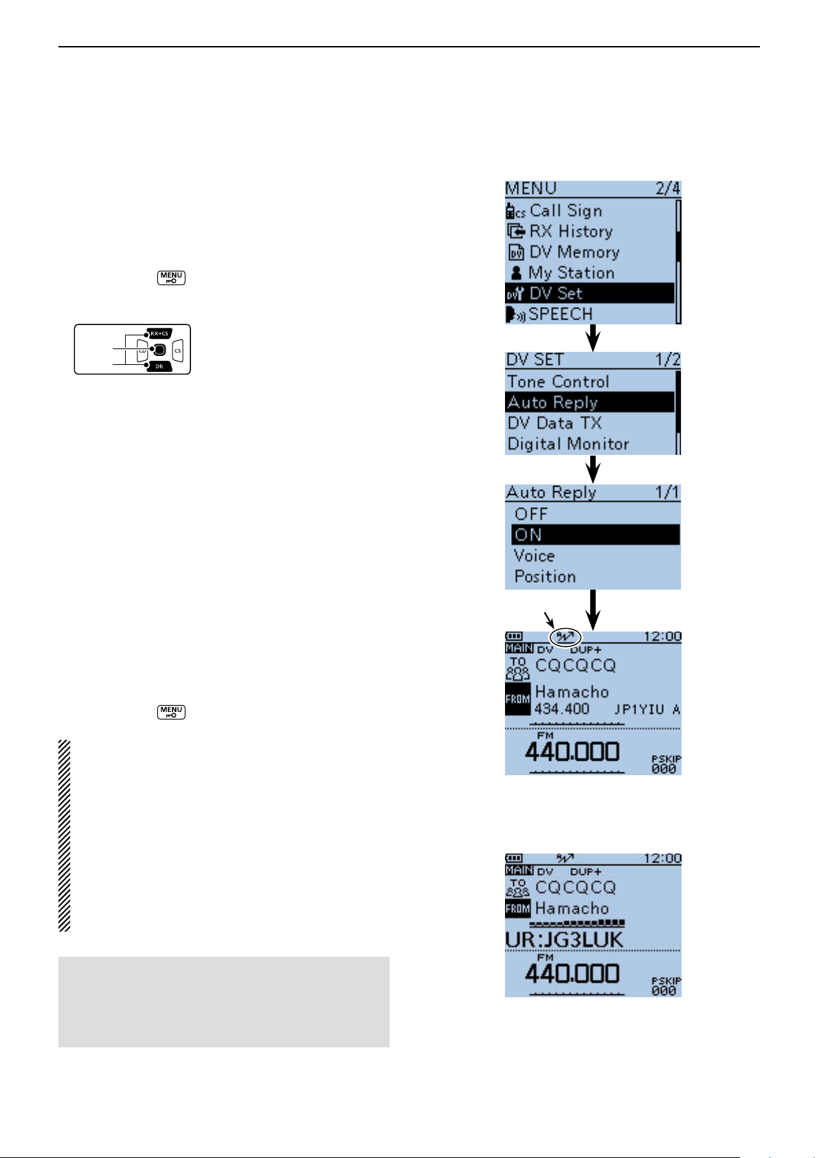
D-STAR OPERATION <ADVANCED>
D-pad
(�)
(Ent)
Previous view
9
■ Automatic Reply function
When a call addressed to your own call sign is received,
the Automatic Reply function automatically replies with
your call sign. (Default: OFF)
Depending on the setting, the recorded message or
your position may be transmitted with the call sign.
Push [MENU] q .
Push D-pad( w ) to select the root item (“DV Set”),
and then push D-pad(Ent).
Push D-pad( e ) to select “Auto Reply,” and then push
D-pad(Ent).
Push D-pad( r ) to select “ON,” “Voice” or “Position.”
• ON : Replies with your own call sign. (No audio reply
is sent)
• Voice : Replies with your call sign and any Auto Reply
message recorded on the microSD (up to 10
seconds).
If no microSD card is inserted or no message
is recorded, only your call sign is transmitted.
The transmitted audio can be monitored.
• Position : Replies with your own call sign and transmits
your position using the internal GPS receiver.
(p. 9-13)
When “OFF” or “Manual” is set in “GPS Select,”
the internal GPS receiver is temporarily turned
ON.
When “External GPS” is set in “GPS Select,”
the transceiver transmits your position. But if
the external GPS receiver is not connected, the
internal GPS receiver will be activated.
Push [MENU] t to exit the MENU screen.
Appears
NOTE:
• When “ON” or “Voice” is selected, the Automatic
• When “Position” is selected, the Automatic Reply
• The Power Save function is disabled when “ON” or
• The Power Save function is enabled when “Posi-
• The Automatic Reply function cannot be used on
To record the voice signal
You can record a voice announcement for the Auto
Reply function in “DV Auto Reply” on the MENU
screen. (p. 16-27)
(MENU > Voice Memo > DV Auto Reply)
Reply function is automatically turned OFF, when
you push [PTT].
function is kept to ON, even if you push [PTT].
“Voice” is selected.
tion” is selected.
the SUB band.
After receiving a call from “JG3LUK,” the
transceiver automatically sends a reply call.
“TO” setting does not change, but
“UR: JG3LUK (Caller’s call sign)”
is displayed.
9-11
Page 99
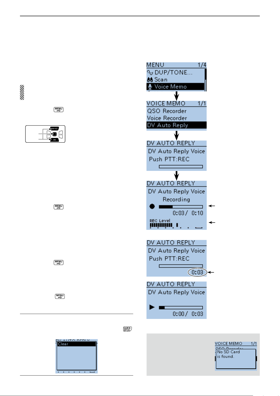
D-STAR OPERATION <ADVANCED>
D-pad
(�)
(Ent)
Previous view
9
Automatic Reply function (Continued) ■
D Recording an Auto Reply voice announcement
The Auto Reply voice announcement can be recorded
and saved on the microSD card to reply to the call with
your voice.
NOTE: Be sure to insert a microSD card to the [micro SD] slot of the transceiver before starting to record a voice signal.
Push [MENU] q .
Push D-pad( w ) to select the root item (“Voice
Memo”), and then push D-pad(Ent).
Push D-pad( e ) to select “DV Auto Reply,” and then
push D-pad(Ent).
Push [PTT] to start recording. (No RF is transmit- r
ted)
• After releasing [PTT], the recording is cancelled.
• Maximum record period is 10 second
• Hold the microphone 5 to 10 cm (2 to 4 inches) from your
mouth, then speak into the microphone at a normal voice
level.
• Only one announcement can be recorded. The current
contents will be overwritten if you record again.
Push [MENU] t to exit the MENU screen.
While recording
D Playing back the recorded voice audio
The recorded voice audio for the Auto Reply function can
be played back.
Push [MENU] q .
Push D-pad( w ) to select the root item (“Voice
Memo”), and then push D-pad(Ent).
Push D-pad( e ) to select “DV Auto Reply,” and then
push D-pad(Ent).
Push D-pad(Ent) to start the playback. r
Push [MENU] t to exit the MENU screen.
Information ✓
You can delete the recorded audio.
On the DV AUTO REPLY screen, push [QUICK] ➥ ,
and then push D-pad(Ent).
Audio level is displayed
Recording time
is displayed
While playing back
When no microSD card is inserted:
When no microSD card is inserted, this error message is
displayed.
9-12
Page 100

D-STAR OPERATION <ADVANCED>
Previous view
9
Automatic Reply function (Continued) ■
D Auto Position Reply function
When you receive a call addressed to your own call
sign, but are in a situation that makes it difficult to operate the transceiver, this function automatically replies
with your own call sign and transmits your position.
Your position is auto- w
matically transmitted.
After receiving the Auto Position Reply call, the destination screen shows your position.
The D-STAR product other than the ID-51 do not show
the position after receiving a call.
A call addressed to q
your own call sign.
Your
station
After receiving, the e
screen shows the
position.
Scrolls your call sign
or the TX message.
• Your status message
may be displayed.
Destination
(ID-51)
After receiving the Auto Position Reply call, the destination
screen shows your position.
• When no valid position is received
After receiving a call addressed to your own call sign,
even if “OFF” or “Manual” is set in “GPS Select,” the
internal GPS receiver is temporarily turned ON for approximately 5 seconds to receive your position.
Then, the transceiver automatically replies with a message, as described below.
When the internal GPS receiver is temporarily turned
ON, and valid data is received, the transceiver automatically replies if a call addressed to your own call
sign is received again.
• Reply message list when no valid position is re-
ceived
Message Status
No Position When no position is received
Old Position 2 minutes or more has passed since
receiving the position.
No Posi & GPS Start The internal GPS receiver is tem-
porarily turned ON, but has not received the position yet.
Old Posi & GPS Start The internal GPS receiver is tem-
porarily turned ON, and 2 minutes
or more has passed since receiving
the position.
Scrolls your
message
After receiving the Auto Position
Reply call, the destination screen
shows your message.
NOTE:
• When “External GPS” is set in “GPS Select,” and
if the external GPS receiver is not connected, the
internal GPS receiver will be activated.
• The position transmission is based on the GPS
transmission mode. (p. 16-40)
• When the settings of GPS transmission mode are
incorrect for the Automatic Reply function, the transceiver automatically correct them to reply a call.
• When the GPS transmission mode is OFF, “GPS-A”
is automatically selected.
9-13
 Loading...