

Page 1

ADVANCED MANUAL
UHF TRANSCEIVER
ID-31A PLUS
ID-31E PLUS
INTRODUCTION
1 ATTACHING ACCESSORIES
2 USING A microSD CARD
3 BATTERY CHARGING
4 D-STAR OPERATION
5 GPS OPERATION
6 VOICE MEMORY FUNCTION
7 MEMORY OPERATION
8 SCANNING
9 PRIORITY WATCH
10 REPEATER AND DUPLEX OPERATIONS
This manual describes instructions for advanced features and
instructions.
See the BASIC MANUAL and the D-STAR GUIDE that come with
the transceiver for precautions and basic operations.
11 MENU SCREEN
12 OTHER FUNCTIONS
13 OPTIONS
INDEX
Page 2

INTRODUCTION
Thank you for choosing this Icom product. This product is designed and built with Icom’ s state of the art technology
and craftsmanship. With proper care, this product should provide you with years of trouble-free operation.
This product combines traditional analog technologies with the new digital technology, Digital Smart Technologies for
Amateur Radio (D-STAR), for a balanced package.
ABOUT THE CONSTRUCTION OF THE MANUAL (As of November 2017)
You can use the following manuals to understand and operate this transceiver.
L If necessary, you can download a glossary of HAM radio terms from the Icom website.
Basic manual (Comes with the transceiver)
Instructions for the basic operations and precautions.
D-STAR GUIDE that explains registering your call
sign to a gateway repeater and the basic operations of
D-STAR is also included.
About the DV Gateway function (PDF type)
Instructions for the system requirements or operations
to use the DV Gateway function.
L “About the DV Gateway function” can be
downloaded from the Icom website.
Advanced manual (This manual)
• Using a microSD card <Advanced>*
• Battery charging <Advanced>*
• Menu screen <Advanced>*
• Memory operation <Advanced>*
• Scan operation <Advanced>*
• D-STAR operation <Advanced>*
• GPS operation
• Voice memory operation
• Priority watch operation
• Repeater and duplex operations
• Other functions
• Options
*The basic instructions are described on BASIC MANUAL.
For Users in California (USA)
This ML414HIV01E Lithium Battery contains
Perchlorate Material—special handling may apply.
See the following URL.
http://www.dtsc.ca.gov/hazardouswaste/perchlorate
Icom, Icom Inc. and the Icom logo are registered trademarks of Icom Incorporated (Japan) in Japan, the United States, the United Kingdom,
Germany, France, Spain, Russia, Australia, New Zealand, and/or other countries.
APRS® is a registered trademark of Mr. Bob Bruninga in the U.S.A. and other countries.
Adobe, Acrobat, and Reader are either registered trademarks or trademarks of Adobe Systems Incorporated in the United States and/or other
countries.
Microsoft and Windows are registered trademarks of Microsoft Corporation in the United States and/or other countries.
Google, the Google Logo, Google Play, the Google Play logo, Android, and the Android logo are trademarks of Google, Inc.
All other products or brands are registered trademarks or trademarks of their respective holders.
Icom is not responsible for the destruction, damage to, or
performance of any Icom or non-Icom equipment, if the
malfunction is because of:
• Forcemajeure,including,butnotlimitedto,res,
earthquakes,storms,oods,lightning,othernatural
disasters, disturbances, riots, war, or radioactive
contamination.
• The use of Icom transceivers with any equipment that is
not manufactured or approved by Icom.
i
Page 3
INTRODUCTION
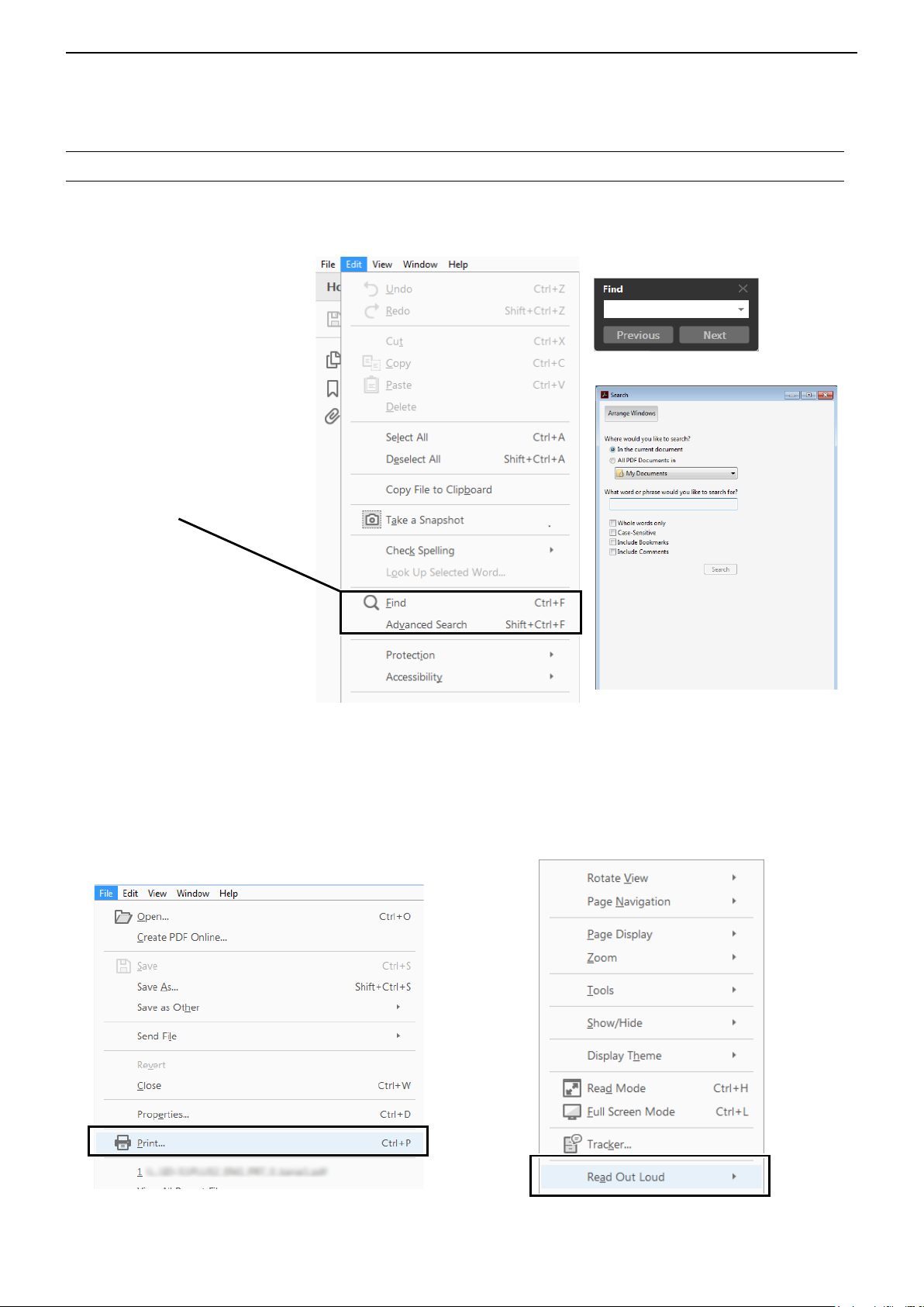
Functions and features of Adobe® Acrobat® Reader
The following functions and features can be used with Adobe Acrobat Reader.
• Keyword search
Click “Find” (Ctrl+F) or “Advanced
Search” (Shift+Ctrl+F) in the Edit
menu to open the search screen.
This is convenient when
searching for a particular word or
phrase in this manual.
* The menu screen may differ,
depending on the Adobe Acrobat
Reader version.
Clicktoopenthendorsearch
screen or advanced search screen.
•Findscreen
•Advancedsearchscreen
®
• Printing out the desired pages.
Click “Print” in the File menu, and then select the
paper size and page numbers you want to print.
* The printing setup may differ, depending on the
printer. Refer to your printer’s instruction manual
for details.
* Select "A4" size to print out the page in the origi-
nal manual size.
• Read Out Loud feature.
The Read Out Loud feature reads aloud the text in
this PDF.
Refer to the Adobe Acrobat
Reader Help for the
details.
( This feature may not be usable, depending on your
PC environment including the operating system.)
* The screen may differ, depending on the Adobe Acrobat Reader version.
ii
Page 4
INTRODUCTION
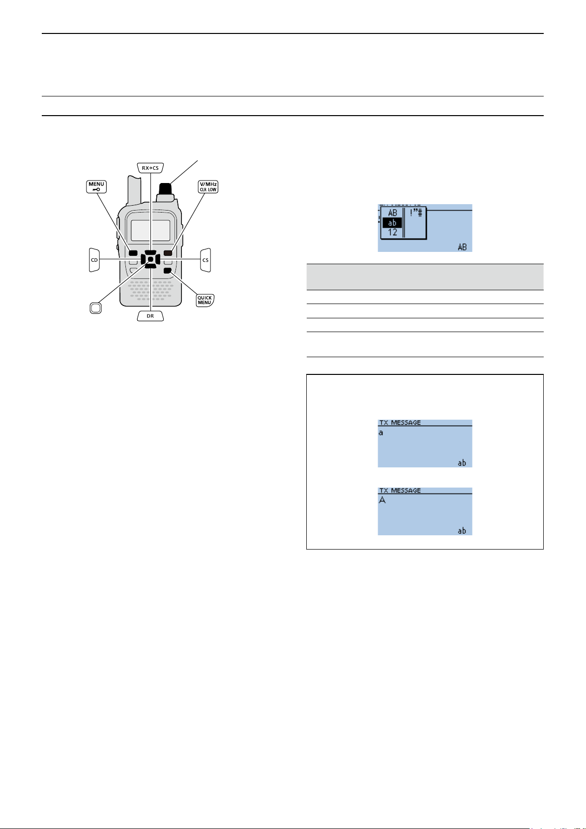
Entering and editing text
Controls used for text entry
Selects a character
Moves the cursor
to the left
[DIAL] (Rotate)
Selects a character
[ENT]
Sets
Selects a character
• To insert a text, move the cursor to a place to enter,
then rotate [DIAL] or push [RX→CS]/[DR].
• To clear a character, push [CLR].
• To consecutively clear characters, continuously hold
down [CLR].
Clears the entryCancels
Moves the cursor
to the right
Opens the Entry
Mode Select widow
To change the character type
1. When not selecting text, or an entered text is
selected, push [QUICK].
2. Rotate [DIAL] to select the character type, then
push [ENT].
Character
type
AB
ab
12
!”#
Selectable characters
and symbols
A to Z, 0 to 9, (space)
a to z, 0 to 9, (space)
0 to 9, (space)
! " # $ % & ’ ( ) * + , - . / : ; < =
> ? @ [ \ ] ^ _ ` { | } ˜ (space)
Character
conversion
A/a
A/a
–
–
TIP: When the character type is “AB” or “ab,” and
while entering a character, push [QUICK] to select
upper case or lower case letters.
▲▼
Push [QUICK]
iii
Page 5

INTRODUCTION
Entering and editing text (Continued)
D Usable characters
The usable characters and symbols, and the maximum characters differ, depending on the item.
See the following list for details.
L The usable characters and symbols for each character type are described at the bottom of the page.
Category Item Character type
Memory mode
Program scan Scan name [AB] [ab] [12] [!”#] 16 –
P-LINK Scan Link name [AB] [ab] [12] [!”#] 16 –
My Station TX Message [AB] [ab] [12] [!”#] 20 – p. 8-7
GPS TX Mode
SD Card
Repeater List
CS screen
My Call Sign Call sign A to Z, 0 to 9, /, (space) 12 (+1)
Your Call sign
GPS Memory
DR screen
DTMF Memory DTMF code 0 to 9, A, B, C, D, *, # 24 – p. 12-6
Memory name [AB] [ab] [12] [!”#] 16 –
Bank name [AB] [ab] [12] [!”#] 16 –
Unproto Address [AB] [ab] [12] [!”#] 56
Comment [AB] [ab] [12] [!”#] 43
GPS Message [AB] [ab] [12] [!”#] 20 – p. 5-19
Save Setting [AB] [ab] [12] [!”#] 15
Export [AB] [ab] [12] [!”#] 15
Group name [AB] [ab] [12] [!”#] 16 – p. 4-40
Repeater name [AB] [ab] [12] [!”#] 16 –
Call sign A to Z, 0 to 9, /, (space) 8 –
GW Call sign A to Z, 0 to 9, /, (space) 8 – p. 4-34
UR A to Z, 0 to 9, /, (space) 8 –
R2 A to Z, 0 to 9, /, (space) 8 –
Name [AB] [ab] [12] [!”#] 16 –
Call sign A to Z, 0 to 9, /, (space) 8 –
Memory name [AB] [ab] [12] [!”#] 16 – p. 5-20
Group name [AB] [ab] [12] [!”#] 16 – p. 5-23
Direct Input (UR) A to Z, 0 to 9, /, (space) 8 – p. 4-11
Direct Input (RPT) A to Z, 0 to 9, /, (space) 8 – p. 4-12
Maximum
characters
Information Reference
Normally 12 characters
(API31,DSTAR*)
The number of characters you
can enter differs, depending on
the data extension and altitude
settings.
Illegal characters:
/ : ; * < >
Illegal characters:
/ : ; * < >
Includes “/” between the Call
sign and Memo field.
p. 7-9
p. 5-13
p. 11-16
p. 2-2
p. 2-8
p 4-33Sub name [AB] [ab] [12] [!”#] 8 –
p. 11-19R1 A to Z, 0 to 9, /, (space) 8 –
p. 11-23
p. 4-41
[AB]: A to Z, 0 to 9, (space)
[ab]: a to z, 0 to 9, (space)
[12]: 0 to 9, (space)
[!”#]: ! " # $ % & ’ ( ) * + , - . / : ; < = > ? @ [ \ ] ^ _ ` { | } ˜ (space)
iv
Page 6
INTRODUCTION
Entering and editing text (Continued)
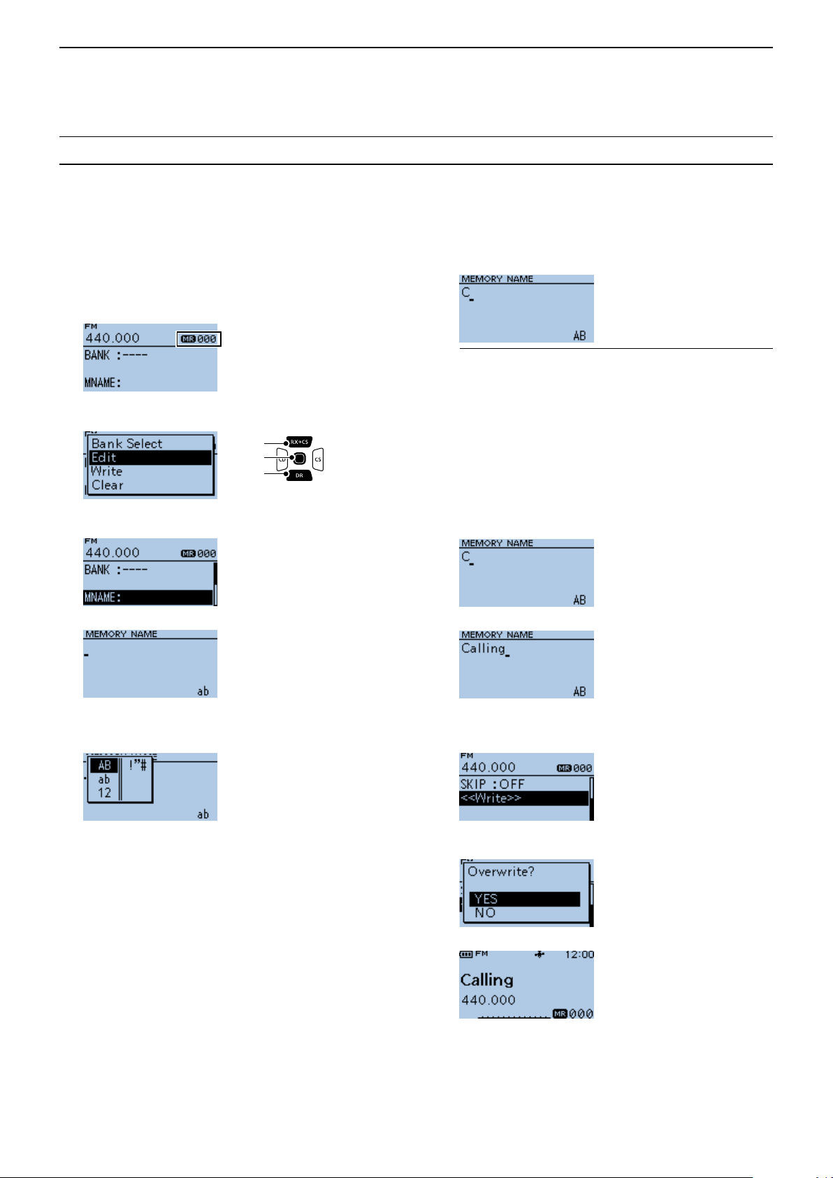
D How to enter
Example: Entering “Calling” as a Memory name.
1. Push [M/CALL] to enter a Memory mode.
2. Hold down [S.MW] for 1 second.
• Enters the Select Memory Write mode.
• The Memory channel number blinks.
3. Rotate [DIAL] to select a Memory channel.
4. Push [QUICK].
5. Select “Edit.”
[Up]
[ENT]
[Down]
• The Edit screen is displayed.
6. Select “MNAME”.
▼
9. Rotate [DIAL] to select a character, then push
[ENT].
(Example: C)
InformationL
• To move the cursor forward, push [CS].
• To move the cursor backward, push [CD].
• To insert a text, move the cursor to a place to enter,
then rotate [DIAL].
• To clear a character, push [CLR].
• To consecutively clear characters, continuously hold
down [CLR].
• When the character type is “AB” or “ab,” and while
entering a character, push [QUICK] to select upper
case or lower case letters.
10. Repeat steps 7 ~ 9 to enter a name.
(Example: Calling)
11. After entering, push [ENT].
• MEMORY NAME screen is displayed.
7. Push [QUICK].
8. Select the character type.
L To enter symbols, select [!”#].
• Returns to the Edit screen and the entered name is
displayed.
12. Select “<<Write>>.”
• Aconrmationdialogisdisplayed.
13. Select <YES>.
▼
• Returns to the Memory mode.
v
Page 7

Section 1
ATTACHING ACCESSORIES
Attaching the antenna.............................................................................1-2
Attaching and detaching the battery ......................................................1-2
Attaching and detaching the belt clip ......................................................1-3
Attaching the hand strap.........................................................................1-3
1-1
Page 8
1
ATTACHING ACCESSORIES
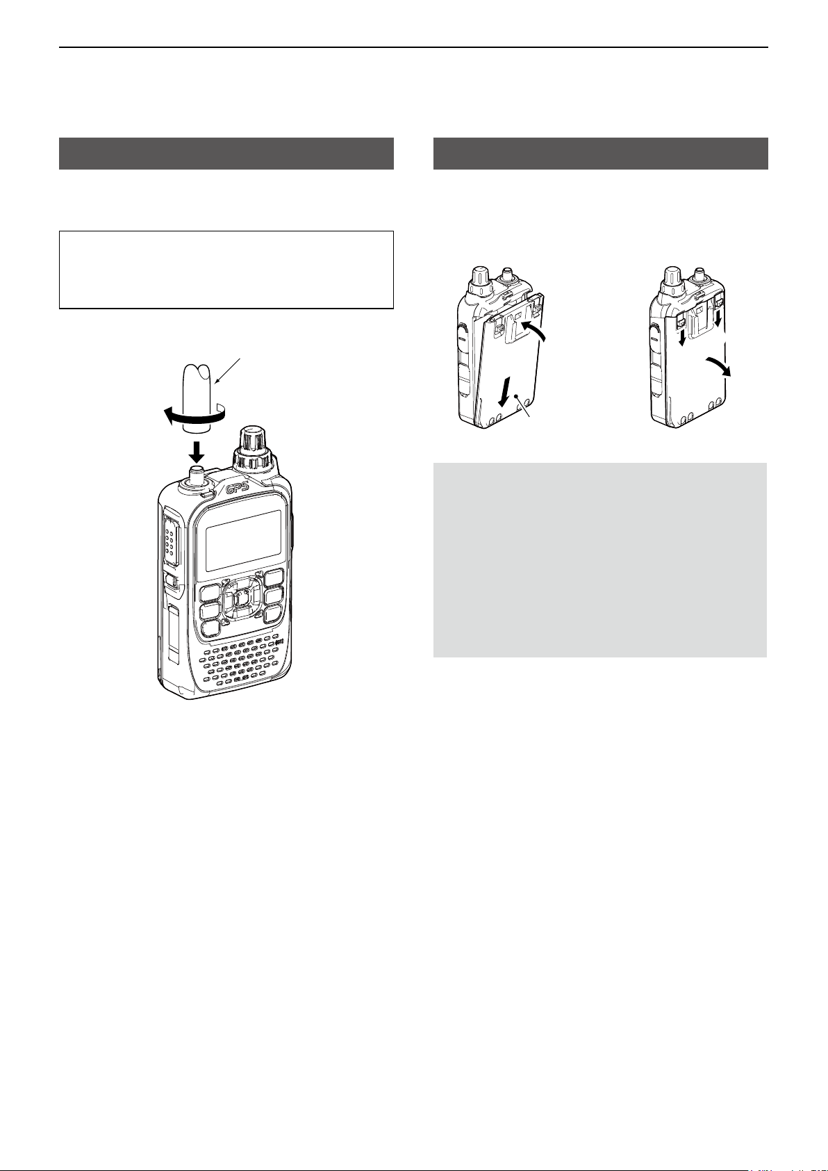
Attaching the antenna
Insert the antenna into the base of the SMA antenna
connector and tighten the antenna.
TIP: Third-party high gain antennas may increase
transceiver performance. The optional AD-92SMA
antenna connector adapter enables you to use
antennas with a BNC connector. (p. 13-2)
Antenna
Attaching and detaching the battery
To attach or detach the battery pack or battery case,
see the illustration below. See page 3-4 for battery
case details.
To attach
w
q
Battery pack or
battery case
NOTE:
• Even when the transceiver is turned OFF, a small
current still ows in the transceiver. When not
using the transceiver for a long time, remove the
battery pack or case to prevent the batteries from
becoming exhausted.
• The battery protection function automatically
reduces power to Low 1 power (0.5 W) when the
temperature is around 0°C (32°F) or below. In
addition, High, Mid and Low 2 power selections
are disabled.
To detach
q
q
w
1-2
Page 9
1
ATTACHING ACCESSORIES
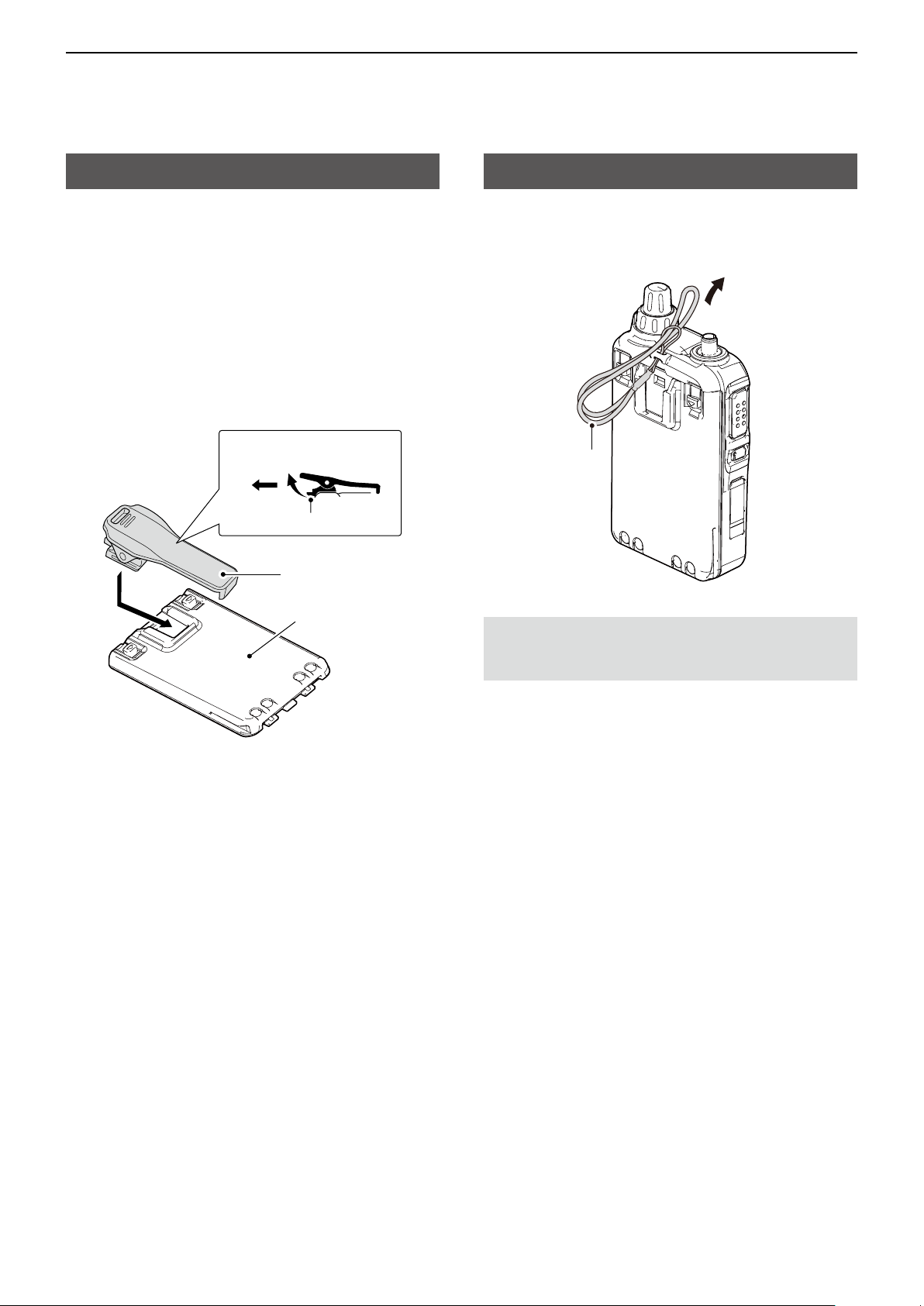
Attaching and detaching the belt clip
To attach or detach the belt clip, rst remove the
battery pack or case, if it is attached. (p. 1-2) See the
illustration below.
To attach the belt clip, slide the belt clip in the
direction of the arrow until the belt clip locks in place,
and makes a ‘click’ sound.
To detach the belt clip, lift the tab up (q), and slide the
belt clip in the direction of the arrow (w).
To detach
q
To attach
w
Tab
Belt clip
Battery pack
or battery case
Attaching the hand strap
Slide the hand strap through the loop on the top of the
rear panel, as illustrated below.
Hand strap
R WARNING! NEVER swing the transceiver by holding
the hand strap. This can cause injury to yourself or
others.
1-3
Page 10

Section 2
USING A microSD CARD
NOTE: See BASIC MANUAL
Section 6 for details on how to
insert or remove a microSD card
and precautions�
About data saved on a microSD card �����������������������������������������������������2-2
Saving settings onto a microSD card �����������������������������������������������������2-2
D Saving as a new le ������������������������������������������������������������������������ 2-2
D Overwriting a current le ����������������������������������������������������������������� 2-2
Saving with a different le name �������������������������������������������������������������2-3
Loading the saved les on the microSD card �����������������������������������������2-4
Backing up data saved on the microSD card onto a PC ������������������������2-5
D About the microSD card’s folder �����������������������������������������������������2-5
D Making a backup le on your PC ����������������������������������������������������2-6
Importing or Exporting a CSV format le ������������������������������������������������2-7
D Importing ����������������������������������������������������������������������������������������� 2-7
D Exporting ����������������������������������������������������������������������������������������� 2-8
2-1
Page 11
2
USING A microSD CARD
About data saved on a microSD card
The following data can be saved onto the card:
• Transceiver data
Memory channel contents, Repeater List, Your (UR)
call sign memory, and GPS memory that are saved
in the transceiver�
• Communication audio
The transmitted and received audio�
• Communication log
The QSO log and RX history log.
Saving settings onto a microSD card
Memory channels, settings on the MENU screen, and
Repeater List can be saved on the microSD card.
Saving data on the microSD card enables you
to easily restore the transceiver to its previous
conguration, even if you perform an All reset.
You can save settings data as a new le, or you can
overwrite to the current le.
• Automatic answering voice audio in the DV mode
Voice audio to use with the Auto Reply function in
the DV Mode�
• Voice audio for the Voice TX function
Voice audio to use with the Voice TX function.
• Position data from the GPS receiver
Position and time data from a GPS receiver that is in
a log le as a route.
• Voice Recorder
The microphone audio�
5� Push [ENT]�
6� Select <YES>.
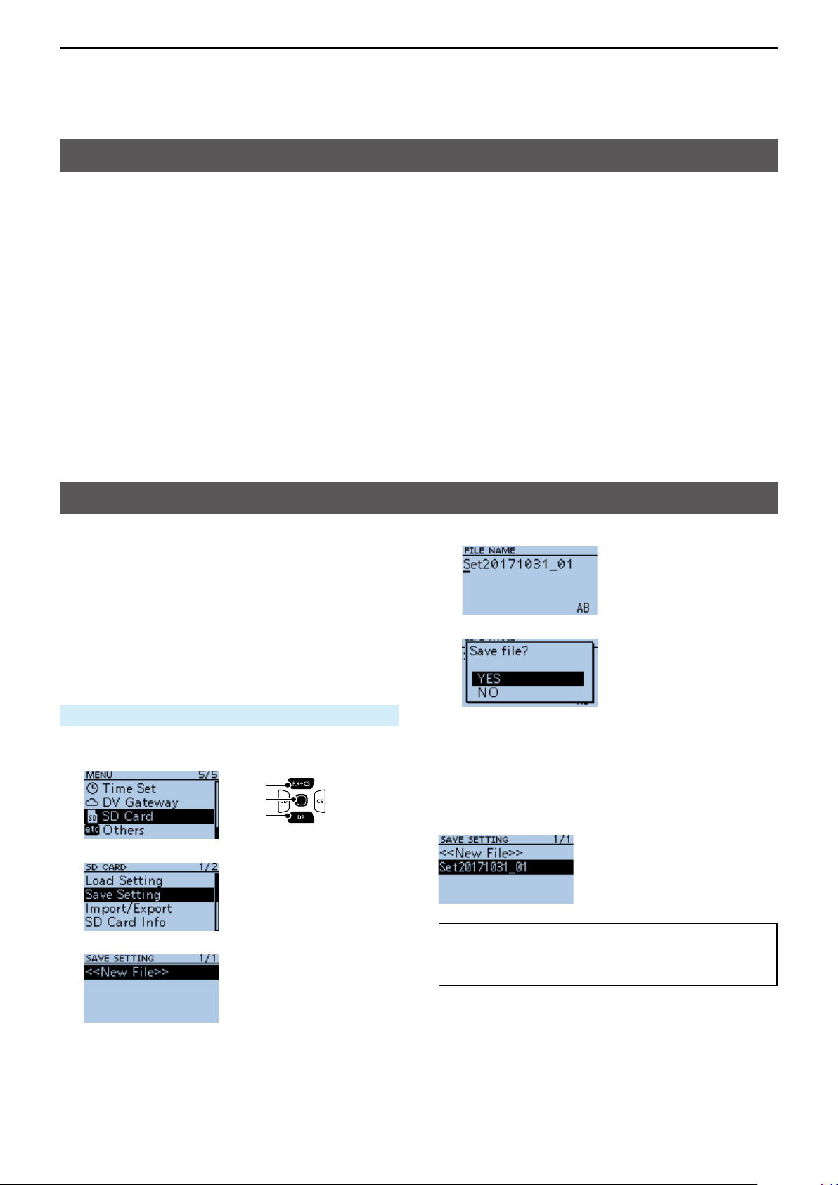
D Saving as a new le
MENU > SD Card > Save Setting
1� Push [MENU]�
2� Select “SD Card.”
[Up]
[ENT]
[Down]
3� Select “Save Setting.”
4� Select “<<New File>>.”
• The le is named in the following format:
Setyyyymmdd_xx
(yyyy: Year, mm: month, dd: day, xx: le number).
L To change the le name, see page iii on how to enter
characters�
• While saving, a progress bar is displayed. When
saving is completed, the SD CARD screen is
displayed.
L To exit the MENU screen, push [MENU].
D Overwriting a current le
To overwrite data in a current le, select the le you
want to overwrite in step 4 to the left.
TIP: Data is saved in the “icf” le format. You can
copy the icf data on a PC and edit it using the
CS-31PLUS cloning software�
2-2
Page 12
2
USING A microSD CARD
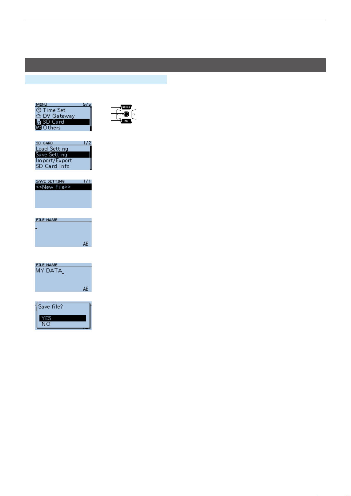
Saving with a different le name
MENU > SD Card > Save Setting
1� Push [MENU]�
2� Select “SD Card.”
[Up]
[ENT]
[Down]
3� Select “Save Setting.”
4� Select “<<New File>>.”
5� Hold down [CLR] to delete the characters.
6� Enter a file name and push [ENT].
L See page iii on how to enter characters�
7� Select <YES>.
• While saving, a progress bar is displayed. When
saving is completed, the SD CARD screen is
displayed.
L To exit the MENU screen, push [MENU].
2-3
Page 13
2
USING A microSD CARD
Loading the saved les on the microSD card
The saved Memory channels, MENU screen settings,
and Repeater List can be copied to the transceiver.
This makes it easy to copy Memory channels or the
Repeater List, to another ID-31A PLUS/ID-31E PLUS
and operate with the same data�
NOTE: Saving the current data is recommended
before loading other data into the transceiver.
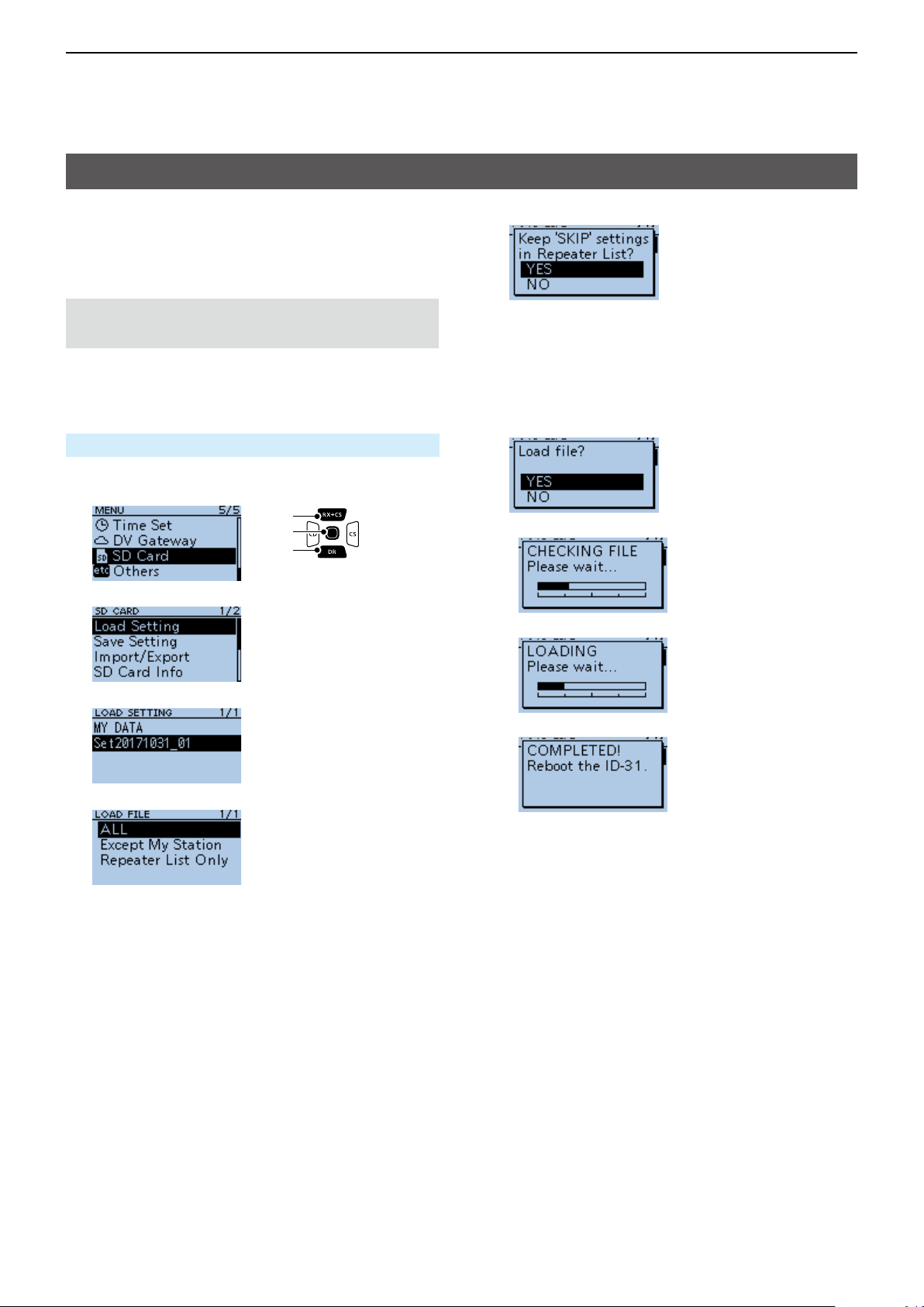
Example: Loading all the data in the
“Set20171031_01” le
MENU > SD Card > Load Setting
1� Push [MENU]�
2� Select “SD Card.”
[Up]
[ENT]
[Down]
3� Select “Load Setting.”
6� Select <YES> or <NO>.
• YES:
The skip settings of the Repeater List are
retained�
• NO:
The skip settings of the Repeater List are
cleared.
7� Select <YES>.
• The data le is checked.
• After checking, loads the data le.
4� Select a data file to load into the transceiver.
5� Select a loading content.
• ALL:
Loads all Memory channels, settings on the
MENU screen, and the Repeater List into the
transceiver�
• Except My Station:
Loads all memory channels, setting on the
MENU screen except MY call signs, and the
Repeater List into the transceiver.
• Repeater List Only:
Loads only the Repeater List into the transceiver.
• After loading, “COMPLETED!” is displayed.
8� Reboot the transceiver to use with loaded settings
data�
2-4
Page 14
2
USING A microSD CARD
Backing up data saved on the microSD card onto a PC
A backup le enables easy restoration, even if the
data on the microSD card is accidentally deleted.
L If your PC does not have a microSD card slot,
connect a memory card reader (user supplied) to
use the microSD card�
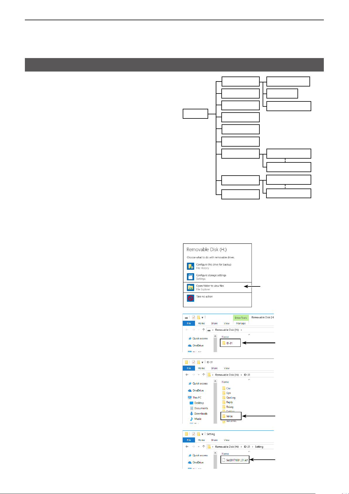
D About the microSD card’s folder
The folders contained in the microSD card:
1� ID-31 folder
The folders created in the transceiver.
2� Csv folder
Repeater List, Your (UR) call sign memory, and
GPS Memory folders.
3� GpsMemory folder
GPS Memory in the “csv” format.
4� RptList folder
Repeater List in the “csv” format.
5� YourMemory folder
Your (UR) call sign memory in the “csv” format.
2� Csv
6. Gps
7� QsoLog
1� ID-31
(Example: Selecting the setting le)
When the microSD card is inserted into the microSD
card slot of your PC or the microSD card reader, the
screen is displayed as shown below.
8. Reply
9. RxLog
10. Setting
11� Voice 12. yyyymmdd
13� VoiceRec
14� VoiceTx
3. GpsMemory
4. RptList
5. YourMemory
12. yyyymmdd
12. yyyymmdd
12. yyyymmdd
6� GPS folder
GPS logging le in the “log” format.
7� QsoLog
QSO log le in the “csv” format.
8� Reply folder
Automatic reply le is saved in the “wav” format.
9� RxLog folder
RX record log le in the “csv” format.
10. Setting folder
Transceiver setting les in the “icf” format.
11� Voice folder
Recorded QSO audio les and folders.
12� yyyymmdd folder
Recorded audio le is saved in the “wav” format.
13� VoiceRec folder
Recorded Voice recorder audio les.
14� VoiceTx folder
Recorded voice audio les for the Voice TX
function in the “wav” format.
Click
▼
Double-click
▼
Double-click
▼
2-5
Setting le
Page 15
2
USING A microSD CARD
Backing up data saved on the microSD card onto a PC
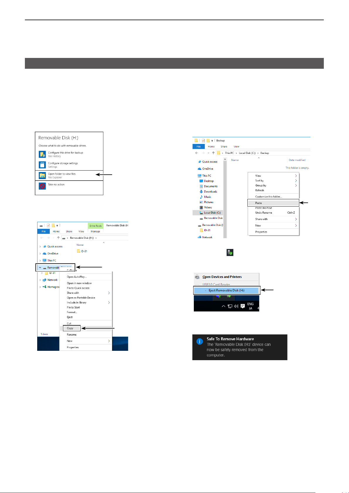
D Making a backup le on your PC
Windows® 10 is used for these instructions.
1� Insert the microSD card into the microSD card
drive or a memory card reader on your PC.
2� Click the “Open folder to view files” option to
access the card�
Click
• Displays the ‘ID-31’ folder.
3� Right-click “Removable disk.”
4� Click “Copy.”
Right-click
5� Open a folder to copy a backup file to, then right-
click, and then click “Paste.”
• Copies the microSD card data onto your hard disk.
(Example: Copying into the “Backup” folder on the
C drive)
Click
6� To remove the microSD card, click the remove
media icon (“ ” in the screen shot shown below)
in the task bar�
Then, click “Eject Removable Disk.”
Click
Click
7� When “Safe To Remove Hardware” is displayed,
remove the microSD card�
2-6
Page 16
2
USING A microSD CARD
Importing or Exporting a CSV format le
Read this section before importing or exporting a
Comma Separated Values (CSV) format le from the
microSD card�
You can import or export Your Call Sign, Repeater
List, and GPS Memory.
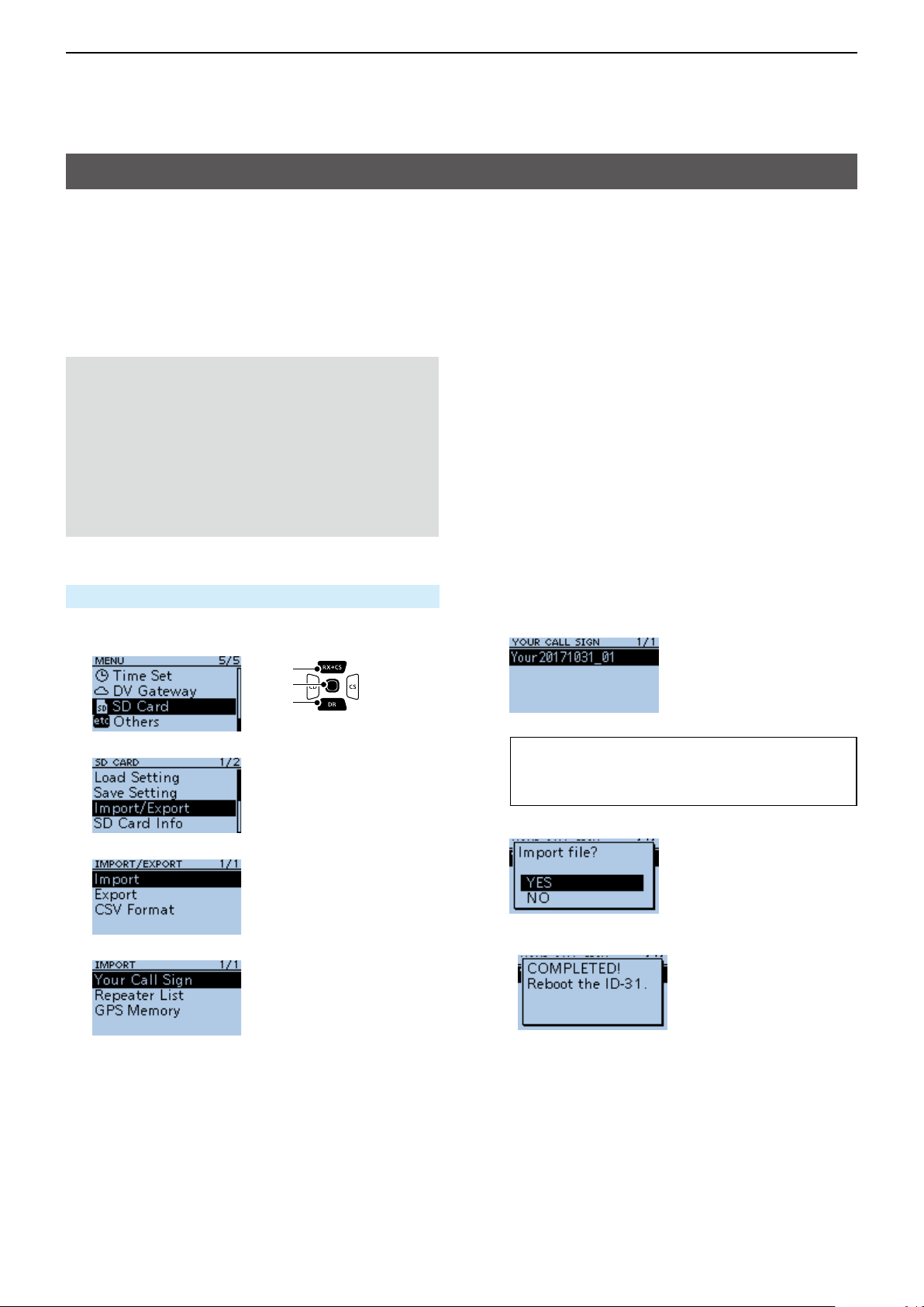
D Importing
NOTE:
• Before importing, make a backup le of all the
transceiver’s data to the microSD card in case of
data loss.
• The transceiver cannot display les that have a
le name longer than 21 characters. If necessary,
rename them using 20 characters or less. When
exporting CSV format les using the CS-31PLUS,
BE SURE the names are 20 characters or less.
Example: Importing the Your Call sign memory.
SD Card > Import/Export > Import
1� Push [MENU]�
2� Select “SD Card.”
[Up]
[ENT]
[Down]
3� Select “Import/Export.”
4� Select “Import.”
5� Select “Your Call Sign.”
6� Select the CSV file to import.
• A conrmation dialog is displayed.
TIP: When importing a Repeater List, “Keep
‛SKIP’ settings in Repeater List?” is displayed.
See step 6 on page 2-4 for details.
7� Select <YES>.
• Starts to import�
• After importing ends, “COMPLETED!” is displayed.
8� To complete the importing, restart the transceiver.
2-7
Page 17
2
USING A microSD CARD
Importing or Exporting a CSV format le
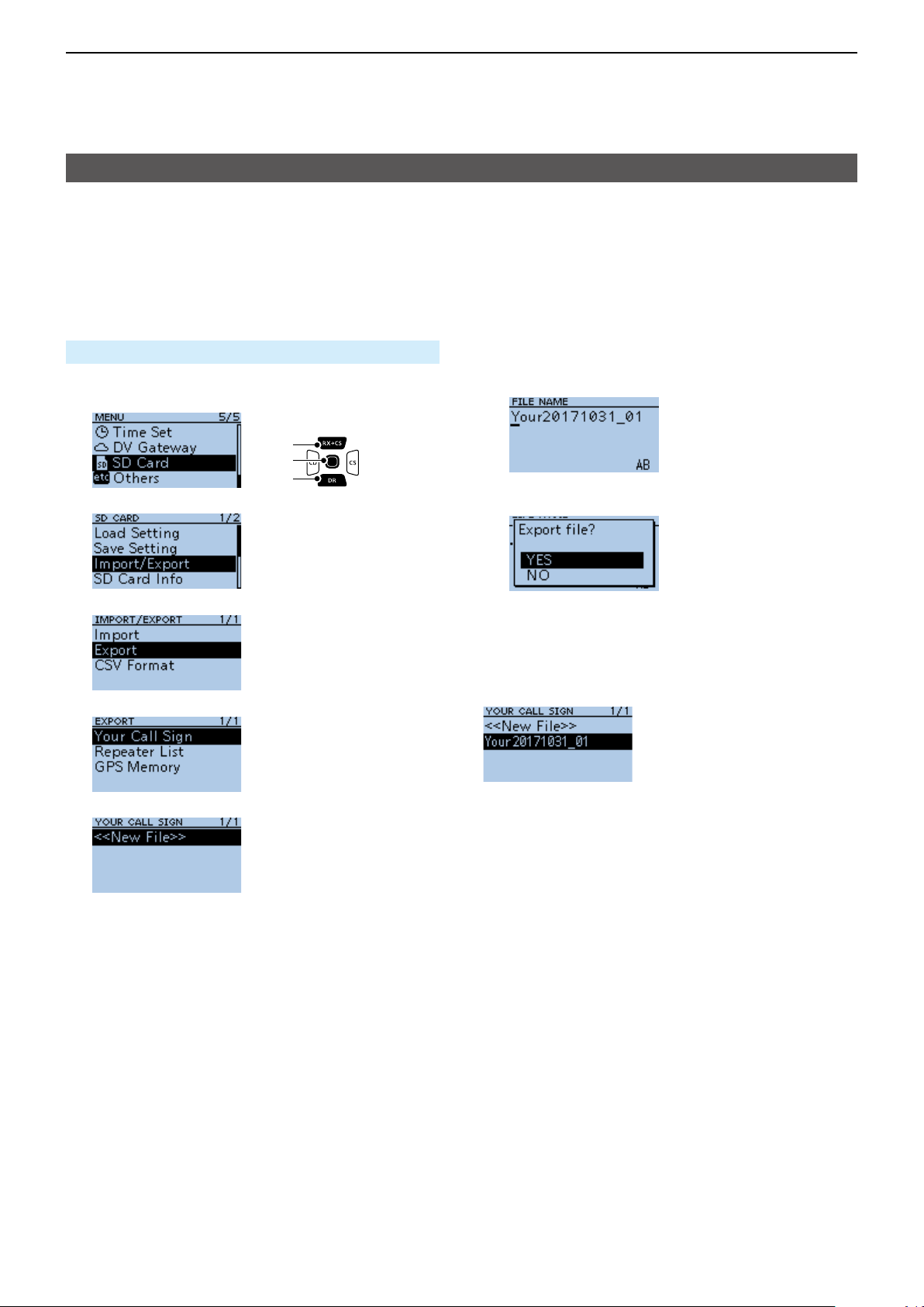
D Exporting
You can export Your Call Sign Memory, Repeater List
and GPS Memory.
Saving as a new le:
Example: Exporting the Your Call sign memory.
SD Card > Import/Export > Export
1� Push [MENU]�
2� Select “SD Card.”
3� Select “Import/Export.”
4� Select “Export.”
5� Select “Your Call Sign.”
6� Select “<<New File>>.”
[Up]
[ENT]
[Down]
7� Push [ENT]�
• A conrmation dialog is displayed.
8� Select <YES>.
• Exports the setting data�
L To exit the MENU screen, push [MENU].
Overwriting a current le:
When you overwrite data in a current le, select the
le you want to overwrite in step 4 to the left.
• Displays the FILE NAME screen.
L The le is named in the following format:
Your*yyyymmdd_xx
(yyyy: Year, mm: month, dd: day, xx: le number).
* “Rpt” is displayed for a repeater list, and “Gps” is
displayed for a GPS memory.
L To change the le name, see page iii.
2-8
Page 18

Section 3
BATTERY CHARGING
Battery information ���������������������������������������������������������������������������������3-2
D Battery life ��������������������������������������������������������������������������������������� 3-2
D Battery icon ������������������������������������������������������������������������������������� 3-2
Charging the battery pack ����������������������������������������������������������������������3-3
D Charging information ����������������������������������������������������������������������3-3
D Charging note ���������������������������������������������������������������������������������3-3
About the optional battery case ��������������������������������������������������������������3-4
D Batteries cautions ���������������������������������������������������������������������������3-4
D Battery life ��������������������������������������������������������������������������������������� 3-4
D About the battery replacement �������������������������������������������������������� 3-4
Charging with the optional desktop charger �������������������������������������������3-5
D Charging note ���������������������������������������������������������������������������������3-5
External DC power operation �����������������������������������������������������������������3-6
D Operating note ��������������������������������������������������������������������������������3-6
Specications for the battery charger and battery pack �������������������������3-7
D BC-202
D BP-271 li-ion battery pack (supplied) ��������������������������������������������3-7
D BP-272 li-ion battery pack (optional) ���������������������������������������������3-7
desktop charger (optional) ����������������������������������������������3-7
3-1
Page 19
3
BATTERY CHARGING
Battery information
D Battery life
The approximate battery life (operating time) as
shown below is calculated under the following
assumptions:
• Power save setting: Auto (Short)
• Duty cycle: TX : RX : Standby = 1 : 1: 8 (based on
operating style)
The approximate battery life:
Battery pack FM mode DV mode
BP-271 4�5 hours 4�5 hours
BP-272 8 hours 7�5 hours
L See page 3-4 for the optional BP-273 battery case
battery life�
NOTE: BE SURE to replace the battery pack with a
new one approximately ve years after purchasing,
even if it still holds a charge� The material inside
the battery cells will become weak after a period of
time, even with little use.
The estimated number of times you can charge the
pack is between 300 and 500� Even when the pack
appears to be fully charged, the operating time of
the transceiver may become short when:
• Approximately ve years have passed since the pack
was manufactured�
• The pack has been repeatedly charged�
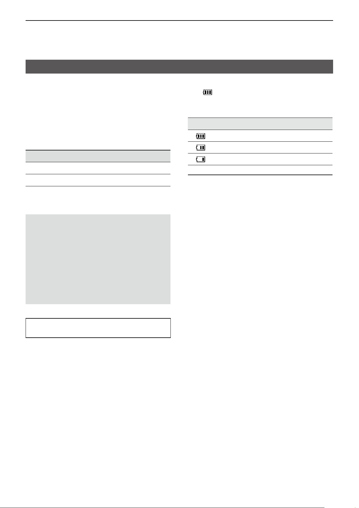
D Battery icon
The “ ” battery icon is displayed when the
BP-271 or BP-272 li-ion battery pack is attached to
the transceiver�
Icon Battery status
The battery has sufcient capacity.
The battery is exhausted a little�
The battery is nearing exhaustion�
Blinking The battery is almost fully exhausted�
TIP: Keep the battery terminals clean� It’s a good
idea to occasionally clean them�
3-2
Page 20
3
desktop charger
BATTERY CHARGING
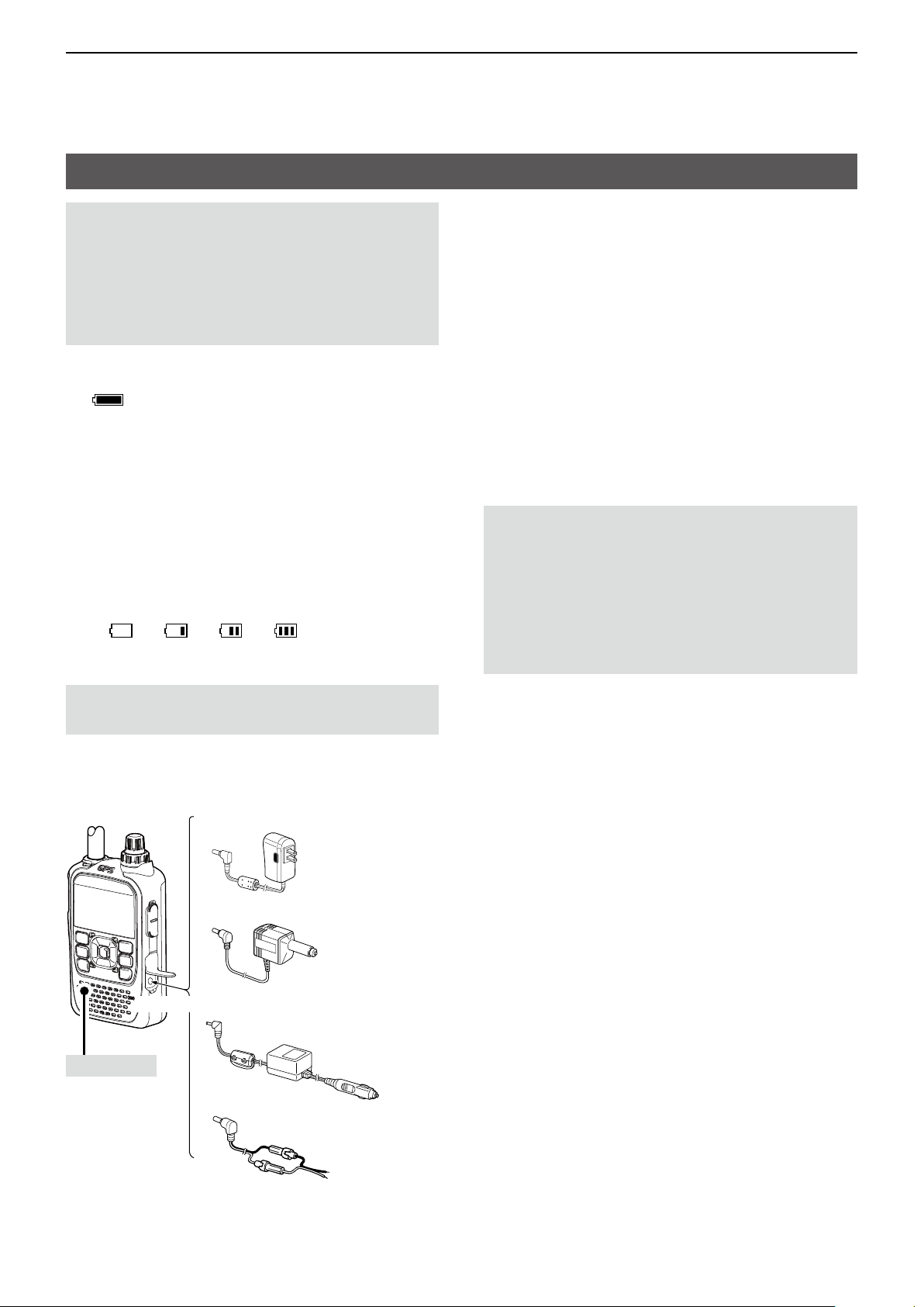
Charging the battery pack
NOTE:
• Prior to using the transceiver for the rst time, the
battery pack must be fully charged for optimum
life and operation�
• BE SURE to turn OFF the transceiver while
charging with the supplied battery charger�
Otherwise the battery pack will not charge�
L While charging, the charging icon
“
” sequentially displays 11 level steps of
“Charging����”
L The icon disappears when the battery pack is
completely charged�
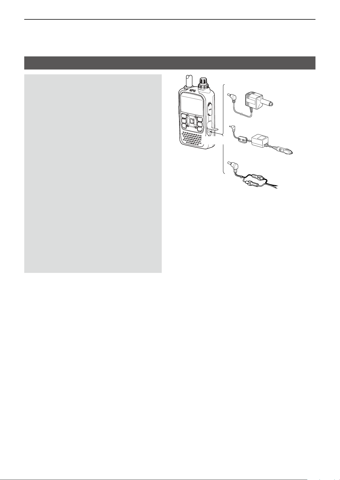
D Charging information
• When using the optional CP-12L, CP-19R, or
OPC-254L, the battery pack can be charged with the
power ON�
L To connect, see the illustration below.
L While charging, the icon display changes, as shown
below�
“ ”→“ ”→“ ”→“ ”
• The BP-273 battery case has no charging capability
or socket�
D Charging note
• Turn OFF the transceiver when using the
BC-167S�
• To protect the battery pack, it cannot be fully
charged when not using the optional BC-202
• DO NOT charge the fully charged battery pack�
This may cause a shorter battery life�
� (p� 3-7)
NOTE: BE SURE to attach the battery pack before
connecting the DC cable
Approximate charging time
• BP-271: 6 hours
• BP-272: 9 hours
BC-167S*1
← To an AC outlet
CP-12L
↑
To a cigarette
lighter socket
(12 V DC)
↓
To a 12 V DC
power source
↓
Black: _
White: +
Turn OFF*
To [DC IN]
2
CP-19R
OPC-254L
*1 The shape is different, depending on the version.
2
*
When using the BC-167S, turn OFF the transceiver.
3-3
Page 21
3
BATTERY CHARGING
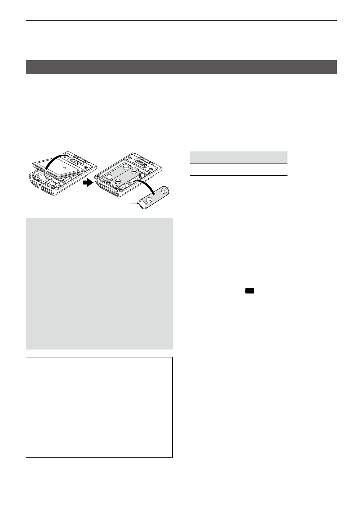
About the optional battery case
The BC-273 uses three AA (LR6) size alkaline
batteries�
1� Remove the battery case top as shown below�
2� Install three AA (LR6) size alkaline batteries�
L Install only alkaline batteries�
L BE SURE to observe the correct polarity�
3� Attach the battery case� (p� 1-2)
BP-273
Alkaline battery
D Batteries cautions
• When installing batteries, conrm that they are
all the same brand, type and capacity. Do not mix
new and old batteries together�
• DO NOT incinerate used battery cells since the
internal battery gas may cause them to rupture�
• DO NOT expose a detached battery case to
water. If the battery case gets wet, BE SURE to
wipe it dry before using it�
• DO NOT use batteries whose insulated covering
is damaged�
• Keep the battery terminals clean� It’s a good idea
to occasionally clean them�
• Remove the alkaline batteries when battery case
is not used� Otherwise the installed alkaline
batteries will exhausted due to the built-in step-up
converter�
D Battery life
The approximate battery life (operating time) as
shown below is calculated under the following
assumptions:
• Power save setting: Auto (Short)
• Duty cycle: TX : RX : Stand-by = 1 : 1: 8 (based on
operating style)
The approximate battery life:
FM mode DV mode
8 hours 6�5 hours
L The battery life may differ, depending on your
operating style, or the installed alkaline batteries.
D About the battery replacement
When the alkaline batteries are almost exhausted,
“LOW BATTERY” is displayed and the battery icon
starts to blink. After 10 seconds, the transceiver power
is automatically turned OFF. In that case, replace all
batteries with new alkaline batteries�
L The battery icon for the BP-273 cannot display the
capacity of the alkaline batteries� The battery icon
always displays “ ,” and it does not reect with
the true battery capacity�
TIP:
• A built-in step-up converter in the BP-273
increases the voltage to 5�5 V DC� Approximately
100 mW of output power is possible using the
case. Also, the transmit output power selection is
disabled�
• The transceiver meets IPX4 requirements
for waterproof protection when the BP-273 is
attached�
• The batteries may seem to have low capacity
when used in low temperatures, such as –10°C
(+14°F) or below. Keep the batteries warm in this
case�
3-4
Page 22
3
BATTERY CHARGING
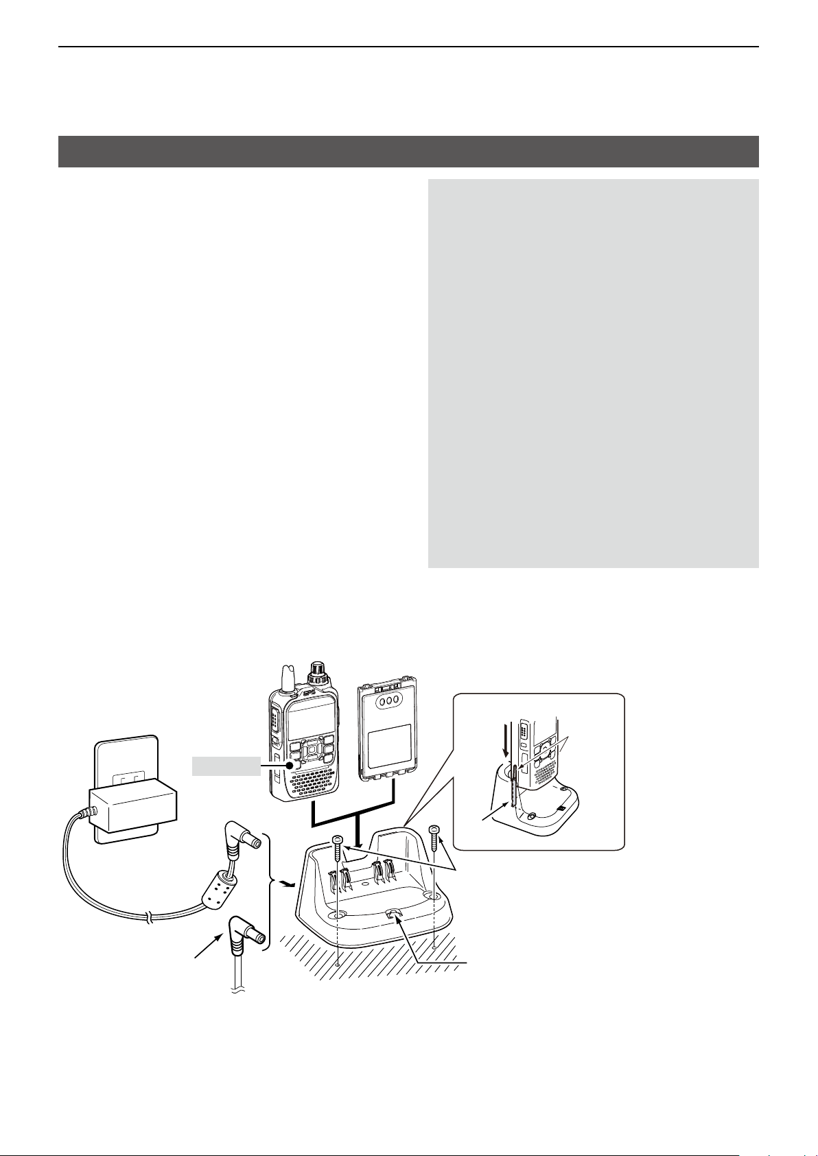
Charging with the optional desktop charger
The optional BC-202 desktop charger rapidly
charges the BP-271 or BP-272 li-ion battery pack�
L The charging indicator lights orange while charging,
and lights green when charging is completed�
Approximate charging time
• BP-271 : 2 hours
• BP-272 : 3�5 hours
D Charging note
R DANGER! NEVER use a battery pack that is not
manufactured or approved by Icom�
• CAUTION: DO NOT place the transceiver with
the battery pack to the desktop charger when the
transceiver is connected to the DC power source�
This may cause the charger’s malfunction� If the
charging indicator lights red, disconnect the power
adapter from the charger, and then reconnect it.
• BE SURE to turn OFF the transceiver� When the
transceiver power cannot be turned OFF because
of the battery exhaustion, detach the battery pack
from the transceiver� Then charge the battery pack
by itself�
• The BC-202 desktop charger can only charge
the BP- 271 or BP-272 li-ion battery pack� Other
types of rechargeable batteries, Ni-Cd or Ni-MH
cannot be charged�
• If the charging indicator blinks orange, there may
be a problem with the battery pack or charger�
Contact your dealer if you have problems charging
a new battery pack�
To an AC outlet
Turn OFF
Power adapter
The CP-23L or OPC-515L
can also be used instead of
the power adapter�
Battery packTransceiver + battery pack
BP-271 or BP-272
BC-202
Guide rail
Tabs
Screws
(Self tapping screws: 3�5 × at least 30 mm)
Purchase separately� Using screws is
recommended to secure the charger�
Charging indicator
• Lights orange: While charging
• Lights green: Charging is completed.
• Blinks orange: A charging error has
occurred�
L Ensure the guide
rails on the battery
pack are correctly
aligned with the
tabs inside the
charger�
3-5
Page 23
3
BATTERY CHARGING
External DC power operation
D Operating note
• DO NOT connect over 16 V DC directly into the
[DC IN] jack of the transceiver� The power source
voltage must be between 10�0 V ~ 16�0 V DC�
• DO NOT transmit at high power for a long period
of time� The transceiver becomes hot and it may
cause a burn�
• Use the optional CP-12L, CP-19R, or OPC-254L
when using the external DC power�
• Con rm the correct polarity of the OPC-254L
supply connection� Connect the OPC-254L to an
external power source (user supplied)�
• Use an external DC-DC converter to connect the
transceiver through the optional CP-12L, CP-19R,
or OPC-254L to a 24 V DC power source� Ask
your dealer for details�
• Up to 5 W (approximately) of maximum output
power is possible when using the external
DC power. However, when the supply voltage
exceeds 14 V, the built-in protection circuit
activates to reduce the transmit output power to
approximately 2�5 W�
• When the external power is used, the Power Save
function (p� 11-33) is automatically turned OFF�
• Depending on the external power voltage,
the battery pack may be used to operate the
transceiver, and the battery pack capacity is
consumed�
CP-12L
↑
CP-19R
To [DC IN]
OPC-254L
To a cigarette
lighter socket
(12 V DC)
↓
To a 12 V DC
power source
↓
Black: _
White: +
L The BC-167S cannot be used for the external DC
power operation�
3-6
Page 24

3
BATTERY CHARGING
Specications for the battery charger and battery pack
D BC-202 desktop charger (optional)
• Power source requirement: 12 V ~ 16 V DC or the specied Icom power adapter (BC-123S)
• Charging temperature range: 0°C ~ 40°C, 32°F ~ 104°F
• Weight: Approximately 104 g, 3.7 oz
(without power adapter)
• Dimensions: 88.0 (W) × 47.5 (H) × 72.5 (D) mm, 3.5 (W) × 1.9 (H) × 2.9 (D) inches
(projections are not included)
D BP-271 li-ion battery pack (supplied)
• Voltage: 7�4V
• Discharge Capacity: 1150 mAh (minimum)
• Usable temperature range: –20°C ~ +60°C, –4°F ~ +140°F
• Charging temperature range: 0°C ~ 40°C, 32°F ~ 104°F
• Storage temperature range: –20°C ~ +50°C, –4°F ~ +122°F (within a month)
–20°C ~ +35°C, –4°F ~ +95°F (within 3 months)
–20°C ~ +20°C, –4°F ~ +68°F (within a year)
• Dimensions: 58 (W) × 86.9 (H) × 9.1 (D) mm, 2.3 (W) × 3.4 (H) × 0.4 (D) inches
(projections are not included)
D BP-272 li-ion battery pack (optional)
• Voltage: 7�4V
• Discharge Capacity: 1880 mAh (minimum)
• Usable temperature range: –20°C ~ +60°C, –4°F ~ +140°F
• Charging temperature range: 0°C ~ 40°C, 32°F ~ 104°F
• Storage temperature range: –20°C ~ +50°C, –4°F ~ +122°F (within a month)
–20°C ~ +35°C, –4°F ~ +95°F (within 3 months)
–20°C ~ +20°C, –4°F ~ +68°F (within a year)
• Dimensions: 58 (W) × 86.9 (H) × 14.2 (D) mm, 2.3 (W) × 3.4 (H) × 0.6 (D) inches
(projections are not included)
3-7
Page 25

Section 4
D-STAR OPERATION
“FROM” (Access repeater) setting..........................................................4-3
D Using your transceiver’s repeater list ..............................................4-4
D Using the DR scan .......................................................................... 4-5
D Using the Near Repeater Search function ...................................... 4-6
D Using TX History .............................................................................4-7
“TO” (Destination) setting .......................................................................4-8
D Using the “Local CQ” (Local Area call) ...........................................4-9
D Using the “Gateway CQ” (Gateway call) ......................................... 4-9
D Using “Your Call Sign” ...................................................................4-10
D Using RX History ..........................................................................4-10
D Using TX History ...........................................................................4-11
D Directly entering (UR) ................................................................... 4-11
D Directly entering (RPT) .................................................................4-12
REPEATER DETAIL screen .................................................................4-13
Connecting to a reector ......................................................................4-14
D What is a reector? ....................................................................... 4-14
D Unlinking a reector ......................................................................4-14
D Linking to a reector .....................................................................4-15
D Using a reector ............................................................................ 4-16
D Reector Echo Testing ..................................................................4-16
D Requesting repeater information ..................................................4-16
Message operation ...............................................................................4-17
D Entering a TX message ................................................................4-17
D Transmitting a message ................................................................4-17
D Deleting a TX message .................................................................4-18
Viewing received call signs ..................................................................4-19
D Viewing the call signs on the RX History screen...........................4-19
BK mode communication......................................................................4-21
EMR communication ............................................................................4-22
D Adjusting the EMR AF level ..........................................................4-22
Automatic DV detection ........................................................................4-23
Automatic Reply function ......................................................................4-24
D Recording an Auto Reply message ..............................................4-25
D Auto Position Reply function ......................................................... 4-26
►Continued on the next page.
4-1
Page 26

Section 4
D-STAR OPERATION
Data communication .............................................................................4-27
D Connection .................................................................................... 4-27
D Data communication application setting .......................................4-27
D Sending data ................................................................................. 4-27
D DV Fast Data function ................................................................... 4-28
Digital squelch functions .......................................................................4-29
D The Digital Call Sign squelch setting ............................................4-29
D Digital call sign squelch function with the Pocket beep ................4-29
D The Digital Code Squelch setting .................................................4-30
D Digital code squelch function with a Pocket beep ......................... 4-30
Repeater list .........................................................................................4-31
D Repeater list contents ...................................................................4-31
Entering new information into the repeater list .....................................4-32
D Required items for the communication cases ............................... 4-32
D Entering new information into the repeater list .............................4-33
Repeater list operation .........................................................................4-37
D Editing repeater data ....................................................................4-37
D Deleting repeater data ..................................................................4-37
D Rearranging the display order of the repeaters ............................4-38
D Adding a new repeater information from RX History ....................4-38
D Skip setting for the DR scan .........................................................4-39
D Entering or editing a repeater group name ................................... 4-40
Your Call Sign .......................................................................................4-41
D Entering Your Call Sign .................................................................4-41
D Deleting Your Call Sign .................................................................4-42
D Rearranging the display order of Your Call Signs .........................4-42
Are your settings correct?.....................................................................4-43
IMPORTANT!
• The repeater list, described in this manual, may differ from your transceiver’s preloaded contents.
• Although Japanese repeaters are used in the setting examples, the Japanese repeater node (port) letters are
different from other country’s.
BE SURE to add the repeater node letter in the 8th digit of the call sign, according to the frequency band
shown below.
1200 MHz : A (B in Japan)
430 MHz : B (A in Japan)
144 MHz : C (no D-STAR repeaters in Japan)
To begin the Digital mode communication using other than the D-STAR Repeater (DR) function
To begin Digital mode communication using other
than the DR function, you can use the VFO mode,
Memory mode, or Call channel mode.
This manual description focuses on the DR function
operation which can be easily set up. If you want to
use other than the DR function, see the procedures
as described to the right, or select the repeater in a
Memory channel.
For a Local area call or Gateway call:
1. Set the access repeater’s frequency. (p. 10-2)
2. Set the frequency offset for the Duplex operation.
(p. 10 - 4)
3. Set the Duplex direction. (p. 10-4)
4. Set the call signs (UR/R1/R2). (p. 11-19)
For a Simplex call:
1. Set the operating mode to the DV mode.
2. Set the operating frequency.
(BASIC MANUAL p. 51)
4-2
Page 27
4
D-STAR OPERATION
“FROM” (Access repeater) setting
Your Access repeater must be set in “FROM” when
you make a call on the DR screen.
You have 5 ways to set the Access repeater.
By rotating [DIAL]
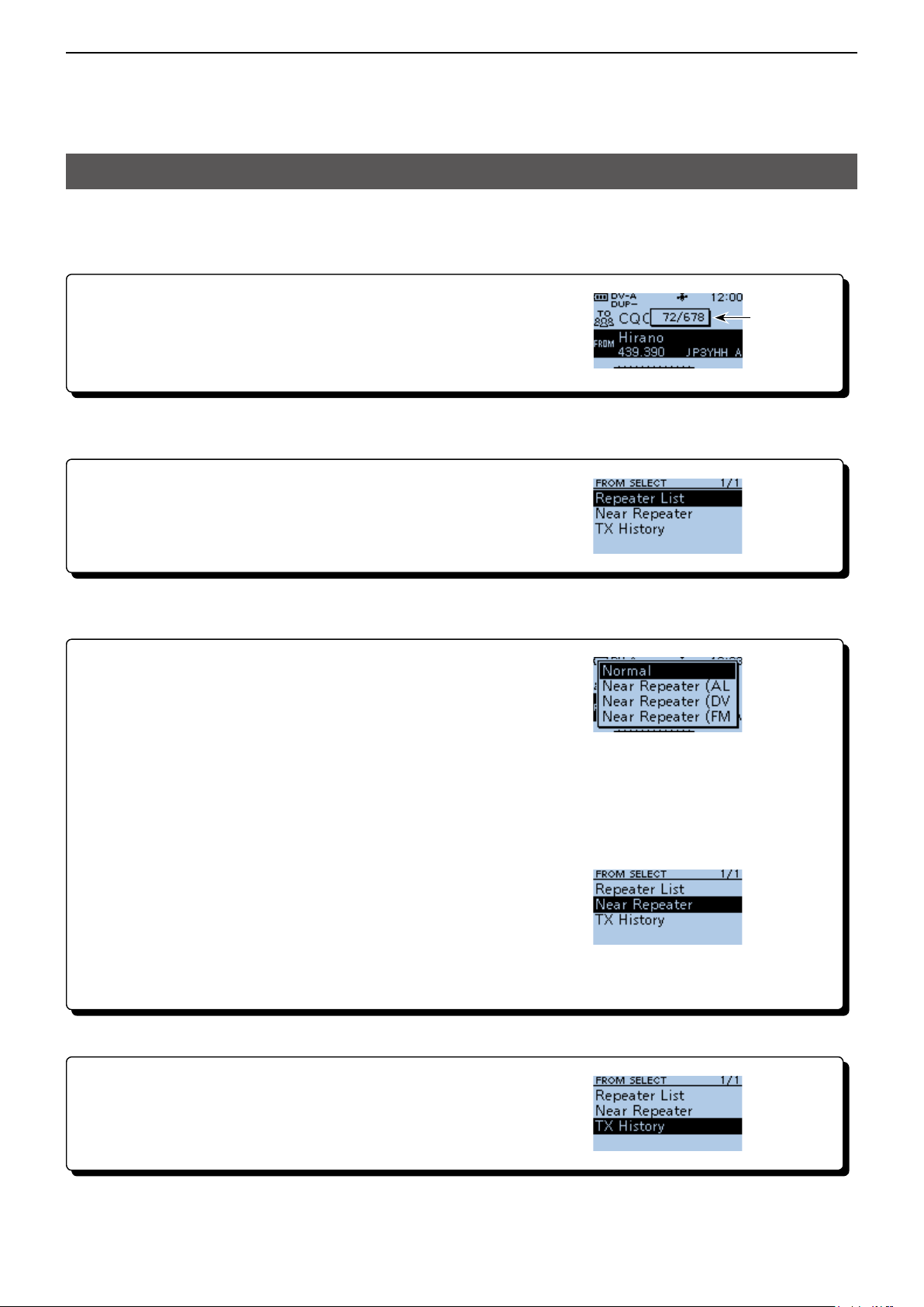
Select the preset repeater by rotating [DIAL] on the DR screen.
• When you know your access repeater
From the repeater list (p. 4-4)
You can select your Access repeater from the repeater list by selecting
the repeater area and name, if entered, or call sign.
Displayed
while rotating
[DIAL]
• When you do not know which repeater you can access
Search for a repeater using the DR scan (p. 4-5)
The Normal DR scan searches for output repeater frequencies of nearby
repeaters. The scan stops when a signal is detected.
• The scan also stops on Simplex signals.
The Near Repeater scan searches for output repeater frequencies of nearby repeaters that are within 160
kilometer (100 miles) from your position and the repeater’s position that is entered in the repeater list. The DR
scan starts scanning and stops when a signal is detected.
You can also nd only FM repeaters using the Near Repeater (FM) scan.
Search for near repeaters (p. 4-6)
Searches for near repeaters that are within 160 kilometer
(100 miles) from your position using your GPS position and the
repeater’s position that is entered in the repeater list.
The nearest repeaters in your transceiver’s repeater list are displayed
as selectable options.
You can select the nearby DV only, FM only, or both repeater types.
• When “FROM” data is saved in the TX History.
From the TX History (p. 4-7)
Select a repeater that you have accessed before from the TX History.
Scan items
4-3
Page 28
4
D-STAR OPERATION
“FROM” (Access repeater) setting
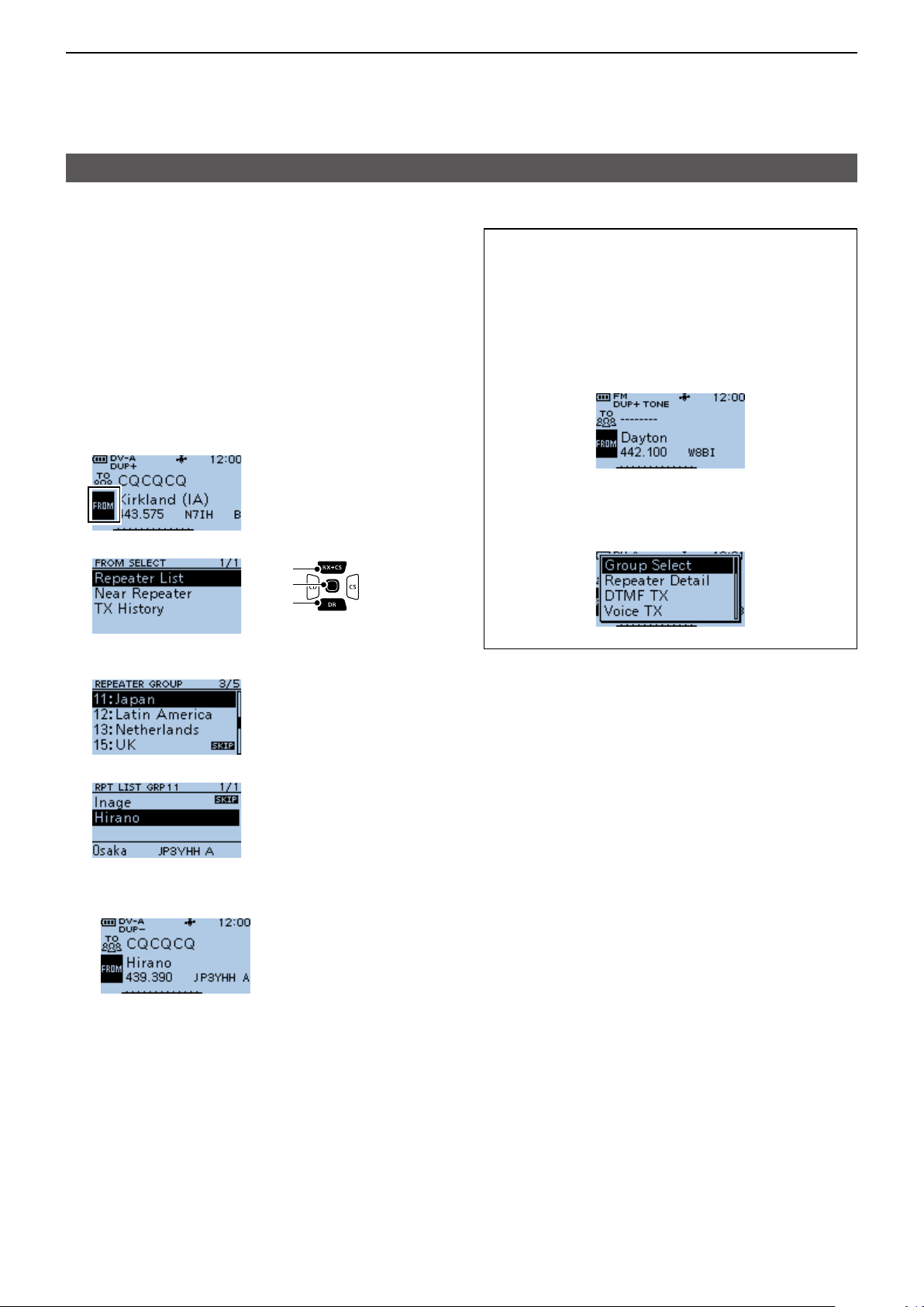
D Using your transceiver’s repeater list
When your access repeater is in your transceiver’s
repeater list, you can select it from the list. By just
selecting the repeater from the list, the repeater call
sign, its frequency, duplex setting, and frequency
offset are automatically set for easy operation.
Example: Selecting the “Hirano” repeater in Japan
from the repeater list.
1. Hold down [DR] for 1 second to display the DR
screen.
2. Push [DR] to select “FROM,” then push [ENT].
3. Select “Repeater List.”
[Up]
[ENT]
[Down]
TIP:
When you select an FM repeater:
When an FM repeater is in your transceiver’s
repeater list, you can select it from the list.
When selecting an FM repeater, the “TO” setting is
not necessary and a “---” is displayed in “TO.”
When selecting an FM repeater.
How to change the repeater group:
To change the repeater group on the DR screen,
push [QUICK], then select “Group Select.”
4. Select the repeater group where your access
repeater is listed.
(Example: “11: Japan”)
5. Select your access repeater.
(Example: “Hirano”)
• Returns to the DR screen, and the selected repeater
name, frequency, and call sign are displayed in
“FROM.”
L The repeater list, described in this manual, may differ
from your transceiver’s preloaded contents.
4-4
Page 29
4
D-STAR OPERATION
“FROM” (Access repeater) setting
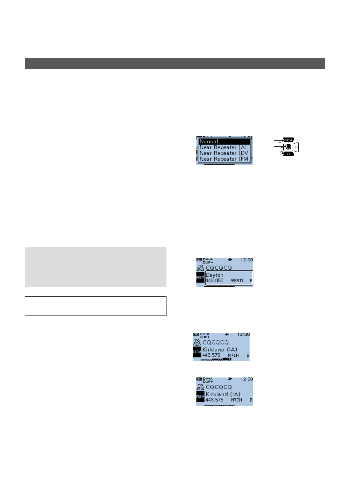
D Using the DR scan
The DR scan scans frequencies to nd a signal on a
repeater or a simplex frequency.
You can use 2 kinds of DR scans, Normal scan and
Near Repeater scan.
Normal scan
To quickly nd a repeater, the Normal scan skips
repeaters that are not set as an access repeater.
L The “USE (FROM)” setting (p. 11-23) is set to “NO”
on the repeater list.
(MENU > DV Memory > Repeater List)
Near Repeater scan
The Near Repeater scan searches for up to 20 nearby
repeaters by using your position and the repeater’s
entered position, and then lists the repeaters.
L The Near Repeater scan continues, even if you
turn OFF the transceiver, and then turn it ON again
during the scan.
L If your own position data is not being received, the
last received position is used.
NOTE: Even if your transceiver receives a repeater
signal, the repeater may not receive your signal,
because the repeater’s output power is higher than
your transceiver’s, and your signal does not reach
the repeater.
TIP: The DR scan scans the simplex frequencies in
the repeater list, in addition to D-STAR repeaters.
Example: Selecting an active repeater using the DR
scan.
1. Hold down [DR] for 1 second to display the DR
screen.
2. Hold down [SCAN] for 1 second.
• Displays the DR scan setting window.
[Up]
[ENT]
[Down]
3. Rotate [DIAL] to select the scan type.
• Normal:
Searches for repeaters whose “USE (FROM)”
setting is set to “YES.”
• Near Repeater (ALL):
Searches for up to 20 nearby DV or FM
repeaters. (Total 40 repeaters)
• Near Repeater (DV):
Searches for up to 20 nearby DV repeaters.
• Near Repeater (FM):
Searches for up to 20 nearby FM repeaters.
4. Push [ENT].
• The selected scan starts.
← The repeaters
are sequentially
displayed.
• In the DR scan, the repeaters are sequentially
displayed by distance, in descending order.
L The scan resumes the same as other scans.
(p. 11-5)
5. When the transceiver receives a signal from a
repeater, the scan stops. Push [SCAN].
4-5
• The DR scan is canceled, and the repeater is set to
“FROM.”
Page 30
4
D-STAR OPERATION
“FROM” (Access repeater) setting
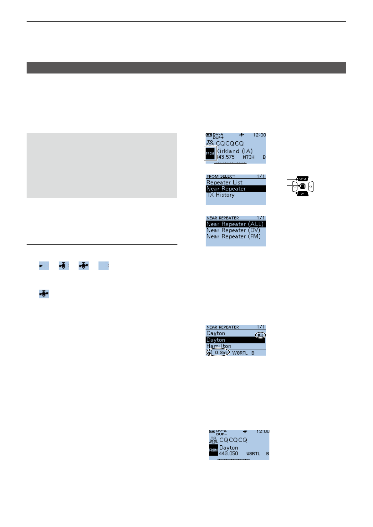
D Using the Near Repeater Search function
The transceiver searches for the nearest repeaters
by using your position and the repeater’s entered
position.
The nearest repeaters in your transceivers’ repeater
list are displayed as selectable options.
NOTE:
• When using the Near Repeater Search function,
BE SURE to rst receive your own position data,
or manually enter your position data.
• If no repeater is found within a 160 kilometer (100
miles) range, “No Repeater Found” is displayed.
• If the last received position can be used, “GPS is
invalid. Search by last valid position” is displayed.
Step 2: Selecting the Access repeater from the
Near Repeater list
1. Hold down [DR] for 1 second to display the DR
screen.
2. Push [DR] to select “FROM,” then push [ENT].
3. Select “Near Repeater.”
[Up]
[ENT]
[Down]
Example: Selecting a nearby repeater from the Near
Repeater list.
Step 1: Receiving your own position from the GPS
satellite
Conrm the GPS receiver is receiving your position.
• The GPS icon blinks when searching for satellites.
→ → →
• The GPS icon stops blinking when the minimum needed
number of satellites is found.
L It may take only a few seconds to receive, or it may take
a few minutes, depending on your operating environment.
If you have difculties receiving, we recommend that you
try a different position.
L If your own position is not being received, the last
received position is used for your location.
4. Select the type of nearby repeater to display.
• Near Repeater (ALL):
Displays up to 20 nearby DV and FM repeaters.
(A total 40 repeaters)
• Near Repeater (DV):
Displays up to 20 nearby DV repeaters.
• Near Repeater (FM):
Displays up to 20 nearby FM repeaters.
5. Select the repeater to use as your access
repeater, considering the distance from your
position to the repeater.
← “FM” is displayed for
FM repeaters.
←Repeater call sign
↑
Distance and direction from
your position to the repeater*
* When the “POSITION” setting (p. 4-35) is set to
“Approximate” on the repeater list, the direction data
is not displayed if the distance to the repeater is less
than 5 kilometers.
(MENU > DV Memory > Repeater List)
• Returns to the DR screen, and the selected repeater is
set in “FROM.”
4-6
Page 31
4
D-STAR OPERATION
“FROM” (Access repeater) setting
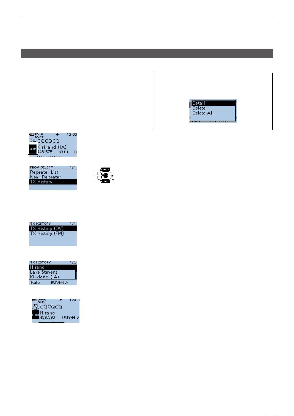
D Using TX History
The TX History saves up to 10 of the latest Access
(From) repeaters you transmitted on. You can select a
repeater from TX History as your Access repeater.
Example: Selecting the “Hirano” repeater from TX
History.
1. Hold down [DR] for 1 second to display the DR
screen.
2. Push [DR] to select “FROM,” then push [ENT].
3. Select “TX History.”
[Up]
[ENT]
[Down]
TIP: When you push [QUICK] in step 5, you can
display the REPEATER DETAIL screen, or delete
the repeater information from the TX HISTORY
screen.
4. Select the TX History (DV) or TX History (FM).
• TX History (DV): Displays the TX History of the
DV repeaters.
• TX History (FM): Displays the TX History of the
FM repeaters.
5. Select the repeater to use it as your Access
repeater.
(Example: “Hirano”)
• Returns to the DR screen, and the selected repeater is
set in “FROM.”
4-7
Page 32
4
D-STAR OPERATION
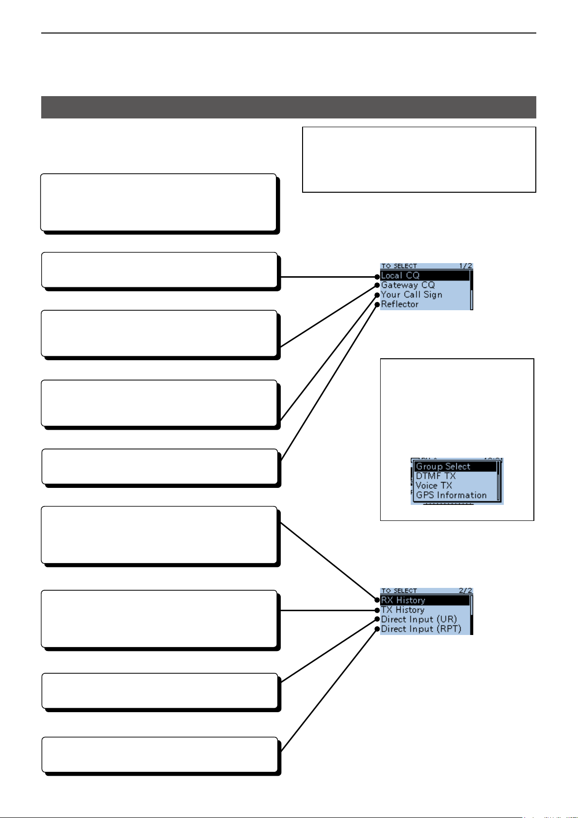
“TO” (Destination) setting
“CQCQCQ,” the destination repeater, or station call
sign must be set in “TO” when you make a call in the
DV mode. You have 8 ways to set the destination.
By rotating [DIAL]
Rotate [DIAL] to select the repeater or Your Call
Sign that is displayed on the DR screen. (This
operation is disabled when “CQCQCQ” is set.)
• To make a Local Area CQ call
“Local CQ” setting (p. 4-9)
Set “CQCQCQ” in “TO” (Destination).
• To make a Gateway CQ call
“Gateway CQ” setting (p. 4-9)
Select a repeater from the repeater List, if you want
to make a Gateway call.
• To make a call to a specic station
“Your Call Sign” setting (p. 4-10)
Select the station call sign in the Your Call Sign
memory.
• To make a call through a Reector
“Reector” setting (p. 4-14)
Select a reector you want to call through.
TIP: After you receive the individual station or
repeater’s signal, the call sign can be captured
by holding down the Call Sign Capture key
([RX→CS]), and you can quickly and easily reply to
a call.
TO SELECT screen
TIP: How to change the
repeater group:
When “Local CQ” or “Gateway
CQ” is selected, you can change
the repeater group.
To change the repeater group on
the DR screen, push [QUICK],
then select “Group Select.”
• To select from RX History
Setting from RX History (p. 4-10)
When you receive a call, repeater or caller station
data is saved in RX History.
Select the destination from the record.
• To select from TX History
Setting from TX History (p. 4-11)
When you make a call, the destination repeater or
called station data is saved in TX History.
Select the destination from the record.
• To directly enter the destination station call sign
Direct Input (UR) (p. 4-11)
Directly enter the destination station’s call sign.
• To directly enter the destination repeater call sign
Direct Input (RPT) (p. 4-12)
Directly enter the destination repeater’s call sign.
4-8
Page 33

4
D-STAR OPERATION
“TO” (Destination) setting
D Using the “Local CQ” (Local Area call)
When “Local CQ” is selected on the TO SELECT
screen, “CQCQCQ” is set in “TO.”
Example: Making a Local area call by accessing the
“Hirano” repeater.
1. Hold down [DR] for 1 second to display the DR
screen.
2. Push [RX→CS] to select “TO,” then push [ENT].
3. Select “Local CQ.”
[Up]
[ENT]
[Down]
• Returns to the DR screen, and “CQCQCQ” is
displayed in “TO.”
D Using the “Gateway CQ” (Gateway call)
When “Gateway CQ” is selected on the TO SELECT
screen, you can select the repeater to make a
gateway call on the repeater list.
Example: Making a Gateway CQ call to the
“Kirkland (IA)” repeater from the “Hirano”
repeater.
1. Hold down [DR] for 1 second to display the DR
screen.
2. Push [RX→CS] to select “TO,” then push [ENT].
3. Select “Gateway CQ.”
[Up]
[ENT]
[Down]
4. Select the repeater group where your destination
repeater is listed.
(Example: “19: USA West”)
5. Select the destination repeater.
L Each repeater has a correct node (A, B or C
band) that you want to transmit on. See page 4-2,
“IMPORTANT” for band letter details.
(Example: “Kirkland (IA)”)
• Returns to the DR screen, and “Kirkland (IA)” is
displayed in “TO.”
TIP: After selecting a destination repeater, you can
select another repeater preset in your repeater List
by rotating [DIAL].
4-9
Page 34
4
D-STAR OPERATION
“TO” (Destination) setting
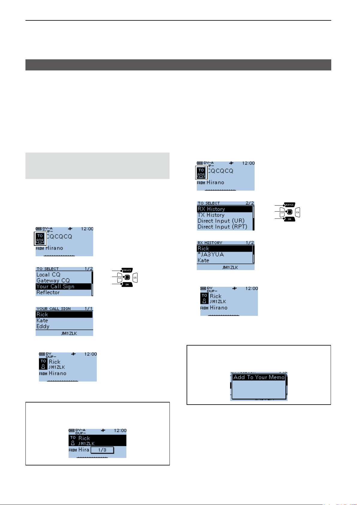
D Using “Your Call Sign”
The “Your Call Sign” memory saves individual or
repeater station call signs. When you select the call
sign for the “TO” (Destination) setting, you can make
a Gateway call. When you call an individual station
through a gateway, the signal is automatically sent to
the last repeater that the individual station accessed.
Therefore, even if you do not know where the
individual station is located, you can make a call.
NOTE: If the repeater, set in “FROM” (Access
repeater) has no Gateway call sign, you cannot
make a gateway call.
Example: Selecting “Rick” from “Your Call Sign.”
1. Hold down [DR] for 1 second to display the DR
screen.
2. Push [RX→CS] to select “TO,” then push [ENT].
D Using RX History
When a call is received in the DV mode, the call data
is saved in the RX History.
Up to 50 callers, and only the last called call signs, a
total of 51 histories can be saved.
Example: Selecting “Rick” in the RX History.
1. Hold down [DR] for 1 second to display the DR
screen.
2. Push [RX→CS] to select “TO,” then push [ENT].
3. Select “RX History.”
[Up]
[ENT]
[Down]
4. Select a destination name or call sign.
(Example: Rick)
3. Select “Your Call Sign.”
[Up]
[ENT]
[Down]
4. Select a destination name or call sign.
(Example: Rick)
• Returns to the DR screen, and “Rick” is displayed in
“TO.”
TIP: After selecting a destination, you can select
another station preset in your transceiver by
rotating [DIAL].
• Returns to the DR screen, and “Rick” is displayed in
“TO.”
TIP: To add an RX HISTORY data to the “Your Call
Sign” memory, push [QUICK], then select “Add To
Your Memory.”
4-10
Page 35
4
D-STAR OPERATION
“TO” (Destination) setting
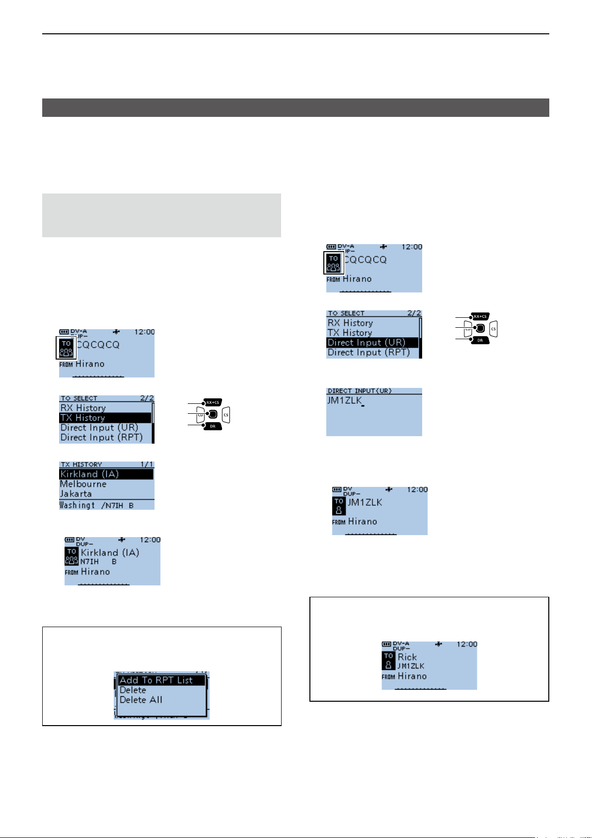
D Using TX History
TX History saves the repeater and station name and
call sign of up to 20 “TO” (Destination) settings that
were used when you made the calls.
NOTE: Until you make a call in the DV mode,
you cannot select “TO” (destination) from the TX
History.
Example: Selecting the “Kirkland (IA)” repeater in the
TX History.
1. Hold down [DR] for 1 second to display the DR
screen.
2. Push [RX→CS] to select “TO,” then push [ENT].
3. Select “TX History.”
[Up]
[ENT]
[Down]
D Directly entering (UR)
The destination station call sign can be directly
entered.
Example: Directly entering the call sign “JM1ZLK.”
1. Hold down [DR] for 1 second to display the DR
screen.
2. Push [RX→CS] to select “TO,” then push [ENT].
3. Select “Direct Input (UR).”
[Up]
[ENT]
[Down]
4. Enter a call sign of up to 8 characters, including
spaces.
4. Select a destination repeater.
• Returns to the DR screen, and “Kirkland (IA)” is
displayed in “TO.”
TIP: You can add the TX HISTORY data to
memory, or delete it from the TX HISTORY screen,
push [QUICK], then select the option.
L See page iii on how to enter characters.
5. After entering, push [ENT].
• Returns to the DR screen, and “JM1ZLK” is displayed
in “TO.”
L After entry, you can correct the call sign in the
DIRECT INPUT (UR) screen.
L The entered call sign remains on the DIRECT INPUT
(UR) screen, until you enter a new call sign.
TIP: If the entered call sign is duplicated in the
“Your Call Sign” memory, the name is displayed.
(Only when the name has been entered.)
4-11
Page 36
4
D-STAR OPERATION
“TO” (Destination) setting
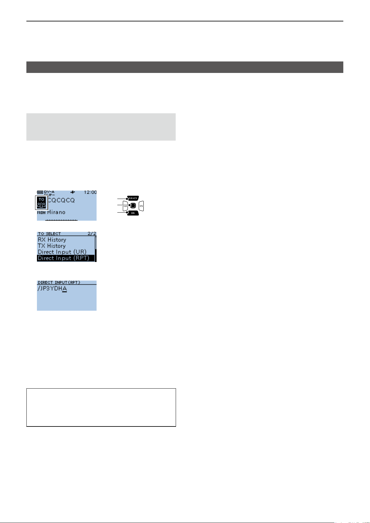
D Directly entering (RPT)
The destination repeater call sign can be directly
entered.
NOTE: BE SURE to include a “/” at the beginning
and the node letter as the 8th digit. See page 4-2
“IMPORTANT” about the node letters.
Example: Directly entering the call sign “/JP3YDHA.”
1. Hold down [DR] for 1 second to display the DR
screen.
2. Push [RX→CS] to select “TO,” then push [ENT].
[Up]
[ENT]
[Down]
3. Select “Direct Input (RPT).”
4. Enter a call sign of up to 8 characters, including
spaces.
L See page iii on how to enter characters.
5. After entering, push [ENT].
• Returns to the DR screen, and “/JP3YDHA” is
displayed in “TO.”
L After entry, you can correct the call sign in the
DIRECT INPUT (RPT) screen.
L The entered call sign remains on the DIRECT INPUT
(RPT) screen, until you enter a new call sign.
TIP:
If the entered call sign is duplicated in the repeater
list, the name is displayed in “TO” (Only when the
name has been entered).
4-12
Page 37

4
D-STAR OPERATION
REPEATER DETAIL screen
Depending on the content, such as position data or
UTC offset, the distance between your position and
the repeater or the repeater time can be displayed on
the REPEATER DETAIL screen.
The detail screen can also be entered from the FROM
SELECT screen.
Example: Displaying the “Hamacho” repeater detail
screen
1. Hold down [DR] for 1 second to display the DR
screen.
2. Push [RX→CS] to select “TO,” then push [ENT].
3. Select “Gateway CQ.”
The REPEATER DETAIL screen
Repeater
frequency
Repeater name
Sub name
Group number
Direction from
your position*
Distance
from your
position
* When the “POSITION” setting (p. 4-35) is set to
“Approximate” on the repeater list, the direction data is
not displayed if the distance to the repeater is less than 5
kilometers.
Call sign
Duplex setting
Repeater time
4. Select “11: Japan.”
5. Select “Hirano.”
L DO NOT push [ENT].
6. Push [QUICK]
7. Select “Detail.”
L If there is no position data, the distance and direction
from your position are not displayed. See page 5-3 to
conrm your position.
L When selecting the FM repeater, either of “FM” or
“FM-N” and the tone setting are displayed.
8. Push [ENT].
• Returns to the previous screen.
TIP: You can display the REPEATER DETAIL
screen when the DR screen is displayed.
When you set the repeater as shown below, push
[QUICK], then select “Repeater Detail.”
▼
• Displays the REPEATER DETAIL screen.
4-13
Page 38
4
D-STAR OPERATION
Connecting to a reector
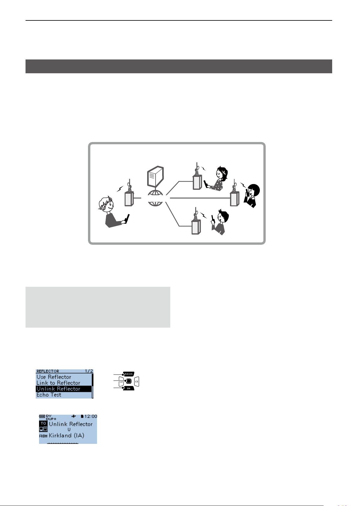
D What is a reector?
A reector is a special server connected to the Internet and running a version of the D-Plus software. If the D-Plus
software is installed on your Access repeater, it provides various functions including gateway and reector linking
capabilities (It is known as the D-STAR reector system). The D-STAR reector system enables a number of
D-STAR repeaters anywhere to link to a reector. This means that when you transmit through a D-STAR repeater
linked to a reector, your voice can be heard on other repeaters linked to the reector, and you can hear other
stations that are connected to the reector.
D-STAR reector system
Reector
Access repeater
→
INTERNET
USA
D Unlinking a reector
Before trying to link to another reector, BE SURE to
unlink the current connected reector.
NOTE: If a reector is already connected, ask on
the air whether or not you can change reectors
and wait for responses. BE SURE to reconnect
back to the same reector when you nish your
conversation.
1. Push [RX→CS] to select “TO,” then push [ENT].
• Displays the TO SELECT screen.
2. Select “Reflector.”
• Displays the REFLECTOR screen.
3. Select “Unlink Reector.”
[Up]
[ENT]
[Down]
CAN
UK
AUS
• Returns to the DR screen, and “Unlink Reector” and
“U” are displayed in “TO.”
4. Hold down [PTT] to unlink the reector.
4-14
Page 39
4
D-STAR OPERATION
Connecting to a reector
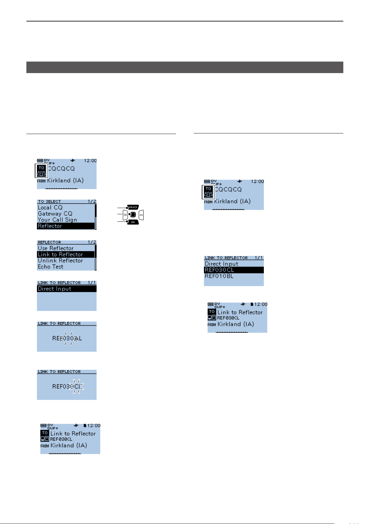
D Linking to a reector
If your repeater is not currently linked to a Reector, or
if you want to change it to another Reector, follow the
steps below. Before linking to another Reector, BE
SURE to unlink the current Reector. (p. 4-14)
Direct inputting a Reector
Example: Directly enter “REF030CL.”
1. Push [RX→CS] to select “TO,” then push [ENT].
2. Select “Reflector.”
[Up]
[ENT]
[Down]
3. Select “Link to Reector.”
4. Select “Direct Input.”
Using TX History
TX History saves up to 5 reectors that your Access
repeater linked to before.
Example: Select the “REF030CL” in TX History.
1. Push [RX→CS] to select “TO,” then push [ENT].
• Displays the TO SELECT screen.
2. Select “Reflector.”
• Displays the REFLECTOR screen.
3. Select “Link to Reector.”
• Displays the LINK TO REFLECTOR screen.
4. Select the reector that you want to link to.
• Returns to the DR screen, and “Link to Reector” and
“REF030CL” are displayed in “TO.”
5. Rotate [DIAL] to select the reector number.
6. Push [CS] to move the cursor to the right box.
7. Rotate [DIAL] to select the module letter.
8. Push [ENT].
• Returns to the DR screen, and “Link to Reector” and
“REF030CL” are displayed in “TO.”
9. Hold down [PTT] to link to the Reflector.
5. Hold down [PTT] to link to the reflector.
4-15
Page 40

4
D-STAR OPERATION
Connecting to a reector
D Using a reector
1. Push [RX→CS] to select “TO,” then push [ENT].
• Displays the TO SELECT screen.
2. Select “Reflector.”
• Displays the REFLECTOR screen.
3. Select “Use Reector.”
• Returns to the DR screen, and “Use Reector” and
“CQCQCQ” are displayed in “TO.”
4. Hold down [PTT] to transmit.
D Reector Echo Testing
To conrm that your signal is correctly getting into the
repeater, you can transmit a short message as a trial.
After releasing [PTT], your message will be played
back.
D Requesting repeater information
When you send the repeater information command, an ID
message is sent back.
1. Push [RX→CS] to select “TO,” then push [ENT].
• Displays the TO SELECT screen.
2. Select “Reflector.”
• Displays the REFLECTOR screen.
3. Select “Repeater Information.”
• Returns to the DR screen, and “Repeater Information”
and “I” are displayed in “TO.”
4. Hold down [PTT] to transmit the repeater
Information command.
5. Release [PTT] to hear the repeater ID message.
1. Push [RX→CS] to select “TO,” then push [ENT].
• Displays the TO SELECT screen.
2. Select “Reflector.”
• Displays the REFLECTOR screen.
3. Select “Echo Test.”
• Returns to the DR screen, and “Echo Test” and “E” are
displayed in “TO.”
4. Hold down [PTT] and speak into the microphone.
5. Release [PTT] to hear your message.
4-16
Page 41

4
D-STAR OPERATION
Message operation
You can save up to 5 short messages in the
transceiver’s memory to transmit in the DV mode.
Each message can be up to 20 characters.
D Entering a TX message
MENU > My Station > TX Message
Example: Entering “JAPAN TOM” into TX message
memory number 1.
1. Push [MENU].
2. Select “My Station.”
[Up]
[ENT]
[Down]
3. Select “TX Message.”
4. Select a TX message memory number.
L Do not push [ENT].
D Transmitting a message
You can transmit a preset TX message by pushing
[PTT] in the DV mode. First, select a TX message
which also turns ON the Message Transmission
function.
MENU > My Station > TX Message
1. Push [MENU].
2. Select “My Station.”
[Up]
[ENT]
[Down]
3. Select “TX Message.”
4. Select a TX message memory number.
5. Push [QUICK].
6. Select “Edit.”
7. Enter a message of up to 20 characters.
(Example: JAPAN TOM)
Selectable characters and symbols
A to Z, a to z, 0 to 9, ! " # $ % & ’ ( ) * +
, - . / : ; < = > ? @ [ \ ] ^ _ ` { | } ˜ (space)
L See page iii on how to enter characters.
8. After entering, push [ENT].
• Returns to the TX MESSAGE screen.
L To not transmit any message, select “OFF.”
L To exit the MENU screen, push [MENU].
InformationL
• The message is transmitted with your voice signal.
• The message is transmitted each time you push
[PTT].
• When continuously transmitting, the selected TX
message is transmitted every 30 seconds.
TIP: RX call sign and message display
As the default, the received call sign and message
are automatically displayed and scrolled.
To not display and scroll them, set RX Call Sign or
RX Message to “OFF.”
(MENU > Display > RX Call Sign, RX Message)
▼
L To exit the MENU screen, push [MENU].
Scrolls
4-17
Page 42

4
D-STAR OPERATION
Message operation
D Deleting a TX message
You can delete the entered TX message.
MENU > My Station > TX Message
Example: Deleting the entered TX message “JAPAN
TOM” from TX message memory number 1.
1. Push [MENU].
2. Select “My Station.”
[Up]
[ENT]
[Down]
3. Select “TX Message.”
4. Select a TX message memory number.
L Do not push [ENT].
5. Push [QUICK].
6. Select “Clear.”
• The conrmation dialog is displayed.
7. Select <YES>.
• Clears the entered message.
L To exit the MENU screen, push [MENU].
4-18
Page 43

4
D-STAR OPERATION
Viewing received call signs
When you receive a DV call, the calling station and
the repeater call signs are saved. Up to 50 calls can
be saved. When you receive the 51st call, the oldest
history is deleted.
L Even if the transceiver is turned OFF, the RX record is
not deleted.
D Viewing the call signs on the RX History screen
1. Hold down [CD] for 1 second.
2. Select an RX history memory to
view the details.
InformationL
• The RX history number, the caller’s name (or call
sign), destination, RX message, RX date and time,
“GW,” and “GPS” are displayed.
• “GW” is displayed when the Gateway call is received.
• “GPS” is displayed when the received call includes
position data.
• “UP” is displayed when the repeater uplink signal is
received.
• In the Quick Menu window, you can select the
following options.
RX>CS: Temporarily sets to the destination.
Call Sign Display: The received data is displayed in
the Call Sign Display mode.
Name Display: The received data is displayed in
the Name Display mode.
Delete: Deletes the selected RX history.
Delete All: Deletes the all RX history.
[Up]
[ENT]
[Down]
3. Push [ENT].
• Displays the RX history detail screen.
InformationL
• Push [Up] or [Down] to view the content.
• In the Quick Menu window, you can select the
following options.
RX>CS: Temporarily sets to the
destination.
Call Sign Display: The received data is displayed
in the Call Sign Display mode.
Name Display: The received data is displayed
in the Name Display mode.
Add to RPT List: Adds the repeater’s call sign to
Repeater List.
Add to Your Memory: Adds the caller station’s call
sign to Your Call Sign.
Delete: Deletes the selected RX
history.
<1st page>
• CALLER: Displays the caller station’s name*2
and any note entered after the call
sign.
• CALLED: Displays the called station
L “CQCQCQ” is displayed when receiving
a Local Area call or Gateway call.
’s name*
.
RX HISTORY screen (RX01)
Displayed when
a Gateway call
is received.
History
number
Caller station*
L A note may be
displayed after “/”.
*1 The displayed icon differs, depending on the D-PRS TX
format.
GPS: Position OBJ: Object
ITEM: Item WX: Weather
2
*
When a name is not entered in the DV Memory, the call
sign is displayed.
2
D-PRS TX
format icon*
Received
date and time
Called station
1
( “CQCQCQ” is
displayed if you
received a CQ call.)
RX message
<2nd page>
4-19
• RXRPT1: Displays the repeater
’s name*2 that
was accessed by the caller station.
If the received call was a Gateway
call, this item displays the gateway
call sign of the repeater you received
the call from.
• RX RPT2: Displays the repeater
’s name*2 you
received the call from.
L The operating frequency is displayed instead
of above items when the call was not through a
repeater (Simplex call).
► Continued on the next page
Page 44

4
D-STAR OPERATION
Viewing the received call signs
D View the call signs on the RX History screen
<3rd page>
• RX MESSAGE: Displays any message included
in the received call, if entered.
<4th page>
• RX TIME: Displays the date and time the
call was received.
<5th ~ 8th page>
Displays position data of the caller station. If a
received signal has no data, then no position data
is displayed.
TIP: “RX RPT1” setting may differ, depending on
the way the call was made.
Example 1: When a Local area call is received.
JM1ZLK
RXRPT1
YOUR STATION
JM1ZLK
calling you...
calling you...
CALLER
CALLED
JM1ZLK
JM1ZLK
calling you...
calling you...
RXRPT2
JM1ZLK
JM1ZLK
calling you...
calling you...
Example 2: When a Gateway call is received.
JM1ZLK calling from
JM1ZLK calling from
JP1YIU port A...
JP1YIU port A...
CALLER
CALLED
JM1ZLK calling from
JM1ZLK calling from
JP1YIU port A...
JP1YIU port A...
JM1ZLK calling from
JM1ZLK calling from
JP1YIU port A...
JP1YIU port A...
RXRPT2
GW
RXRPT1
YOUR STATION
INTERNET
INTERNET
L To exit the MENU screen, push [MENU].
TIP: To delete RX HISTORY data
On the RX HISTORY or the detail screen, push
[QUICK], then select “Delete” or “Delete All.”
4-20
Page 45

4
D-STAR OPERATION
BK mode communication
The Break-in (BK) function enables you to break into a
conversation, where the 2 stations are communicating
with the call sign squelch (DSQL) enabled.
L The BK function is automatically turned OFF when
you turn OFF the transceiver.
MENU > DV Set > BK
1. While 2 stations are communicating in the DV
mode, hold down [RX→CS] for 1 second.
• After releasing [RX→CS], the calling station’s call sign
or the repeater’s call sign is set to “TO” (Destination).
• Beeps sound and the calling station’s call sign is
announced.
L When a call sign is not received correctly, error
beeps sound, and no call sign is set.
2. Push [MENU].
3. Select “DV Set.”
[Up]
[ENT]
[Down]
5. Select “ON.”
6. Push [MENU].
• Returns to the standby screen, and “BK” is displayed.
7. When both stations are in standby, push [PTT] to
4. Select “BK.”
transmit.
L “BK” blinks when receiving a Break-in call.
L To cancel the BK mode, select “OFF” in step 5, or
turn OFF the transceiver.
How to use Break-in?
While using the Digital Call Sign squelch (DSQL), the squelch never opens (no audio is heard) even if a call is
received, unless the call is addressed to your own call sign.
However, when a call including the “BK ON” signal (break-in call) is received, the squelch opens and audio is heard
even if the call is addressed to another station.
Station C calling to Station A with “BK OFF”
Station A
and B are
communicating
using the
Digital Call
Station A Station B
Sign squelch.
Station C
Station C calling to Station A with “BK ON”
Station A
and B are
communicating
using the
Digital Call
Station A Station B
Sign squelch.
Station C
Station B does not hear that
Station C is calling Station A.
Station B also hears that
Station C is calling Station A.
4-21
Page 46

4
D-STAR OPERATION
EMR communication
The Enhanced Monitor Request (EMR)
communication function can be used in only the DV
mode. Using the EMR function, no call sign setting is
necessary.
InformationL
• All transceivers that receive an EMR signal
automatically open their squelch to receive the
signal. DO NOT use this function except in the case
of emergency.
• When an EMR signal is received, the audio (voice)
is heard at the set level, even if the volume setting
level is set to the minimum level.
• The EMR communication function is automatically
turned OFF when you turn OFF the transceiver.
MENU > DV Set > EMR
Example: Transmitting from the “Hirano” repeater
using the EMR function.
1. Push [MENU].
2. Select “DV Set.”
[Up]
[ENT]
[Down]
D Adjusting the EMR AF level
The audio output level when an EMR signal is
received is adjustable between 0 and 39.
When an EMR signal is received, the audio is heard at
the preset level, or the [VOL] control level, whichever
is higher.
To turn OFF the setting, set to “0.”
MENU > DV Set > EMR AF Level
1. Push [MENU].
2. Rotate [DIAL] to select “DV Set.”
[Up]
[ENT]
[Down]
3. Select “EMR AF Level.”
4. Rotate [DIAL] to adjust the EMR audio output level
between 0 (OFF) and 39 (maximum). (Default: 19)
3. Select “EMR.”
4. Select “ON.”
5. Push [MENU].
• Returns to the standby screen, and “EMR” is
displayed.
6. Push [PTT] to transmit.
• The TX/RX indicator lights red while transmitting.
L “EMR” blinks on a station that receives the EMR
signal. The audio (voice) is heard at the set level, or
the [VOL] level, whichever is higher.
L To cancel the EMR mode, select “OFF” in step 4, or
turn OFF the transceiver.
L To exit the MENU screen, push [MENU].
4-22
Page 47

4
D-STAR OPERATION
Automatic DV detection
If you receive an FM signal while in the DV mode, the
“DV” and “FM” icons alternately blink to indicate the
received signal is FM.
When the DV Auto Detect function is ON, the
transceiver automatically selects the FM mode to
temporarily monitor the signal. (Default: OFF)
L Regardless of this setting, the “DV” and “FM” icons
alternately blink if you receive an FM signal while in
the DV mode.
NOTE: When Digital Call Sign squelch (DSQL)
or Digital Code squelch (CSQL) is selected, the
transceiver does not receive FM signals, even if
this function is ON. You can silently wait for calls
from others.
MENU > DV Set > DV Auto Detect
1. Push [MENU].
2. Select “DV Set.”
[Up]
[ENT]
[Down]
3. Select “DV Auto Detect.”
4. Select “ON.”
L To exit the MENU screen, push [MENU].
L When an FM signal is received while in the DV
mode, the “DV” and “FM” icons sequentially blink,
and the transceiver receives the signal in the FM
mode.
When an FM signal is received while in the DV mode
DV Auto Detect function: OFF
The “DV” and “FM” icons alternately blink, but the
audio cannot be heard.
The icons
alternately blink.
▲▼ ▲▼
• • •
You cannot hear
the audio.
DV Auto Detect function: ON
The “DV” and “FM” icons alternately blink, and the
audio can be heard.
Thanks for
The icons
the nice QSO!
alternately blink.
You can hear the
audio!
4-23
Page 48

4
D-STAR OPERATION
Automatic Reply function
When a call addressed to your own call sign is
received, the Automatic Reply function sounds beepds
and automatically replies with your call sign.
(Default: OFF)
Depending on the setting, a recorded message may
be transmitted with the call sign.
NOTE: The Automatic Reply function temporarily
sets the received call sign to “TO” (destination).
TIP: To record the Auto Reply message
You can record the Auto Reply message. See page
4-25 for details.
(MENU > Voice Memo > DV Auto Reply)
MENU > DV Set > Auto Reply
1. Push [MENU].
2. Select “DV Set.”
[Up]
[ENT]
[Down]
3. Select “Auto Reply.”
5. Push [MENU].
• Returns to the standby screen, and displays “ .”
L When “ON” or “Voice” is selected, the Automatic
Reply function is automatically turned OFF, when you
push [PTT].
When “Position” is selected, the Automatic Reply
function remains ON, when you push [PTT].
Example: After receiving a call from “JM1ZLK,” beeps
sound and the transceiver automatically
sends a reply call.
4. Select an option.
• ON: Automatically replies with your own call
sign. (No audio reply is sent)
• Voice: Automatically replies with your call
sign and an Auto Reply message
recorded on the microSD card (up to 10
seconds).
L If no SD card is inserted, or no message
is recorded, replies with your own call
sign (No audio reply is sent).
• Position: Automatically replies with your own call
sign and your position data using the
internal or external GPS receiver.
L When GPS Select is set to “OFF” or
“Manual,” the internal GPS receiver is
temporarily turned ON.
When GPS Select is set to “External
GPS,” but if the external GPS receiver is
not connected, the internal GPS receiver
is temporarily turned ON.
(MENU > GPS > GPS Set > GPS Select)
The “TO” setting does not change, but “UR:
JM1ZLK (Caller’s call sign)” is displayed.
4-24
Page 49
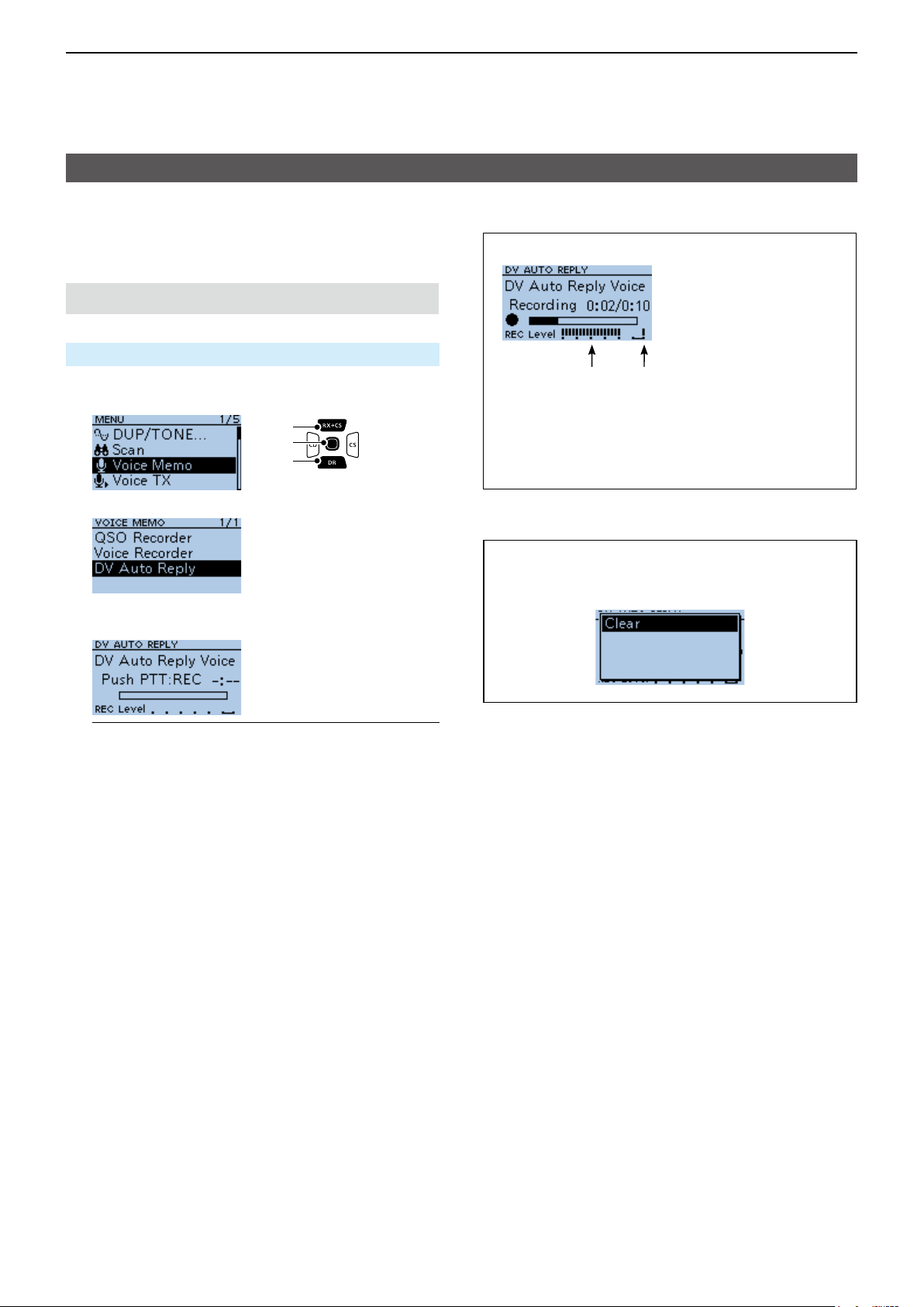
4
D-STAR OPERATION
Automatic Reply function
D Recording an Auto Reply message
You can record the Auto Reply message and saved on
a microSD card to reply to the call with your voice.
NOTE: Conrm a microSD card is in the card slot.
MENU > Voice Memo > DV Auto Reply
1. Push [MENU].
2. Select “Voice Memo.”
[Up]
[ENT]
[Down]
3. Select “DV Auto Reply.”
The DV AUTO REPLY screen
Audio level is
displayed
Adjust the Mic gain so that the
REC Level does not reach to this
range
( MENU > Function > MIC Gain
(Internal), MIC Gain (External))
4. Hold down [PTT] to start a recording, release it to
stop recording.
InformationL
• The Maximum recording time is 10 seconds.
• Hold the microphone 5 ~ 10 cm (2 ~ 4 inches) from
your mouth, then speak at your normal voice level.
• Only 1 message can be recorded. The current
contents is overwritten if you record again.
5. Push [MENU] twice.
• Returns to the standby screen.
TIP: To delete the recorded message, push
[QUICK] on the DV AUTO REPLY screen, then
select “Clear.”
4-25
Page 50
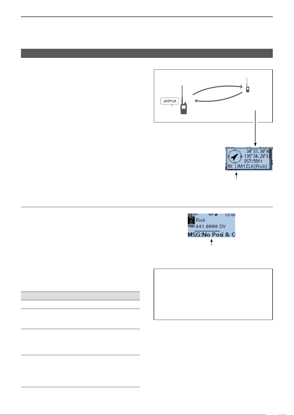
4
D-STAR OPERATION
Automatic Reply function
D Auto Position Reply function
When you receive a call addressed to your own call
sign, but are in a situation that makes it difcult to
operate the transceiver, this function sounds beeps
and automatically replies with your own call sign and
transmits your position data.
After receiving the Auto Position Reply call, the
position
data is displayed in a window.
L Only the Icom transceivers, the ID-31A/E PLUS,
ID-4100A/E, ID-5100A/E, ID-51A/E PLUS, or
ID-51A/E PLUS2, displays the position after
receiving a call.
(As of November 2017)
L You can turn OFF the caller’s position display.
(MENU > Display > Reply Position Display)
(p. 11-40)
caller’s
2. Your position data is
automatically transmitted.
1. A call addressed to
your own call sign.
Your station
3. After receiving, position data is
displayed on the destination’s
transceiver.
Destination
(ID-31A/E
PLUS)
When no valid position data is received
After receiving a call addressed to your own call sign,
the internal GPS receiver is temporarily turned ON for
approximately 5 minutes to receive your position data,
even if GPS Select is set to “OFF,” “External GPS,” or
“Manual.” Then, the transceiver automatically replies
with a message, as described below.
(MENU > GPS > GPS Set > GPS Select)
L When the internal GPS receiver is temporarily ON, and
valid position data is received, the transceiver transmits
your position data if a call addressed to your own call
sign is received again.
Reply message list when no valid position data is
received
Message Status
No Position When no position is received.
2 minutes or more has
Old Position
passed since receiving
position data.
Scrolls your call sign or the TX message.
L Your status message may be displayed.
Scrolls your message.
TIP:
• The position data is transmitted according to the
GPS TX Mode. (p. 11-15)
• When the GPS TX Mode settings are incorrect
for the Automatic Reply function, the transceiver
automatically corrects them to reply to a call.
• When GPS TX Mode is set to “OFF,” “D-PRS” is
automatically selected.
No Posi & GPS Start
Old Posi & GPS
Start
The internal GPS receiver
is temporarily turned ON,
but has not received your
position data yet.
The internal GPS receiver
is temporarily turned ON,
and 2 minutes or more have
passed since receiving
position data.
4-26
Page 51
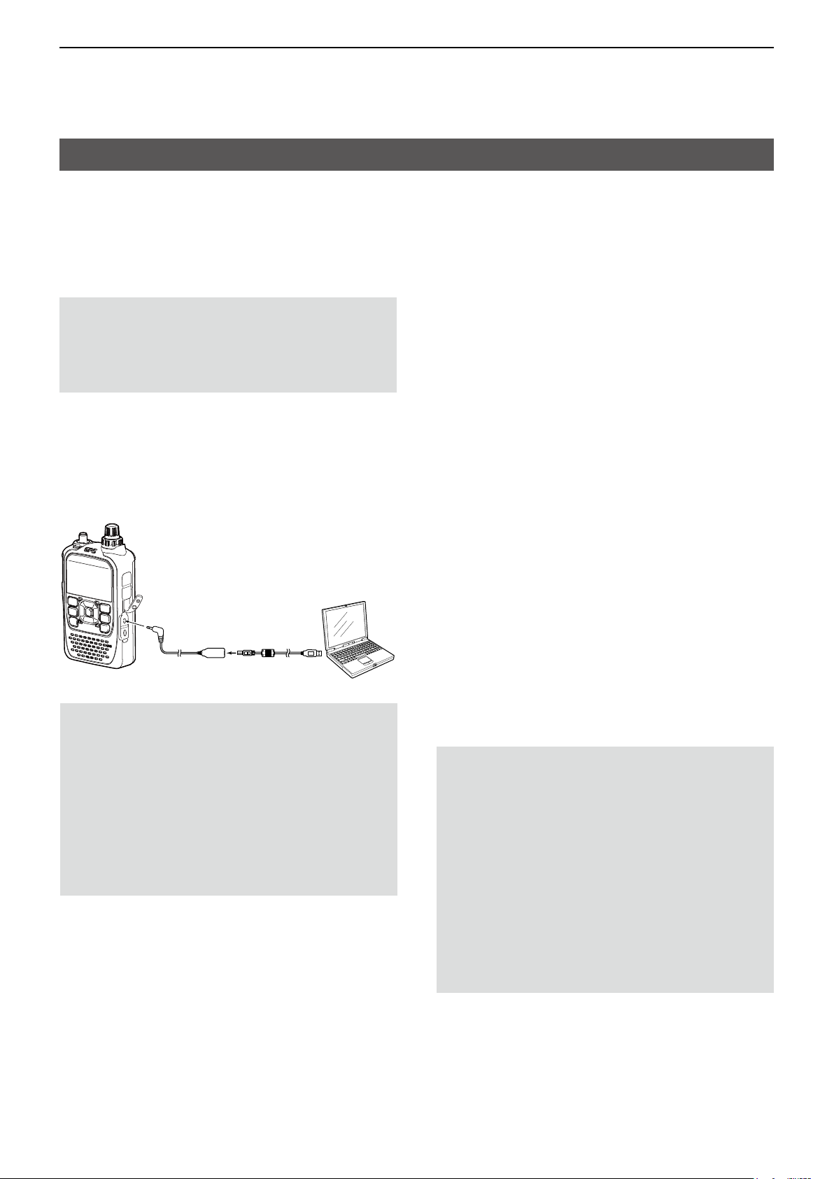
4
D-STAR OPERATION
Data communication
In addition to digital voice communication, you can
send and receive data. Also, you can use the DV Fast
Data function for data communication. (p. 4-28)
To send and receive data, the optional OPC-2350LU
or OPC-2218LU, and a data communication software
(user supplied) are required.
NOTE: DV Data TX is set to “Auto” as the default
setting. When you enter text data into your
communication software, the transceiver may
automatically transmit it, depending on the software
and the software settings.
D Connection
Connect the transceiver to your PC using the optional
OPC-2350LU, as shown below.
Transceiver
To the
[DATA] jack
OPC-2350LU or
OPC-2218LU
To the
USB port
NOTE: Before you start sending data, BE SURE to
set the following items. (pp. 11-9, 11-39)
• Set GPS Select to other than “External GPS.”
(MENU > GPS > GPS Set > GPS Select)
• Set GPS Out (To DATA Jack) to “OFF.”
(MENU >GPS > GPS Set > GPS Out (To DATA
Jack))
• Set CI-V (DATA Jack) to “OFF.”
(MENU > Function > CI-V > CI-V (DATA Jack))
L When using the CI-V function, set CI-V (DATA Jack)
to other than “OFF.”
PC
D Data communication application setting
Set the communication software, as shown below.
• Port: The COM port number that is used by
the ID-31A/E PLUS.*
• Baud rate: 4800/9600 bps*
1
2
• Data: 8 bit
• Parity: none
• Stop: 1 bit
• Flow control: Xon/Xoff
*1 Depending on the PC environment, the COM port number
used by the ID-31A/E PLUS may be higher than 5. In that
case, use an application that can set it to higher than 5.
2
*
Set the baud rate in Data Speed. (p. 11-38)
(MENU > Function > Data Speed)
D Sending data
1. Set your own call sign, the destination call sign,
and the repeater call sign.
2. Follow the instructions of your data
communication application software.
3. When you enter text data into your communication
software, the transceiver may automatically
transmit it, depending on the software and the
software settings.
L When DV Data TX is set to “PTT,” pushing [PTT]
transmits the text data and a voice signal. (p. 11-26)
(MENU > DV Set > DV Data TX)
L Before transmission, the transceiver sends
approximately 500 milliseconds of carrier sense.
NOTE:
• Only ASCII code can be used for data
communication.
• The transceiver has also the Message
Transmission function that transmits up to 20
characters. (p. 4-17)
• Depending on the combination of your PC and
your communication software, some data may be
lost.
• While receiving voice or data through the Internet,
some packets may be lost due to network error
(poor data throughput performance). In such a
case, an “L” is displayed on the screen to indicate
that packet loss has occurred.
4-27
Page 52

4
remote control
software
D-STAR OPERATION
Data communication
D DV Fast Data function
To send data using the DV Fast Data function, follow
the instructions below.
L The DV Fast Data communication can be made by
only the following Icom transceivers:
ID-31A/E PLUS, ID-4100A/E, ID-5100A/E*, or ID51A/E (PLUS, PLUS2, 50th Anniversary model).
(As of November 2017)
* Usable only when rmware versions CPU M 1.10,
S 1.00, C 1.10, and DSP 1.10 or later are installed.
TIP: When you connect the transceiver to an
Android device, you can use the DV Fast Data
function with the RS-MS1A
Transceiver
.
Android
device
NOTE: If you want to send GPS data to other
transceivers that can receive only slow speed data,
set GPS Data Speed to “Slow.” (p. 11-26)
(MENU > DV Set > DV Fast Data > GPS Data Speed)
DV Set > DV Fast Data > Fast Data
1. Push [MENU].
2. Select “DV Set.”
3. Select “DV Fast Data.”
4. Select “Fast Data.”
OPC-2350LU
To the
USB port
5. Select “ON.”
L To exit the MENU screen, push [MENU].
4-28
Page 53
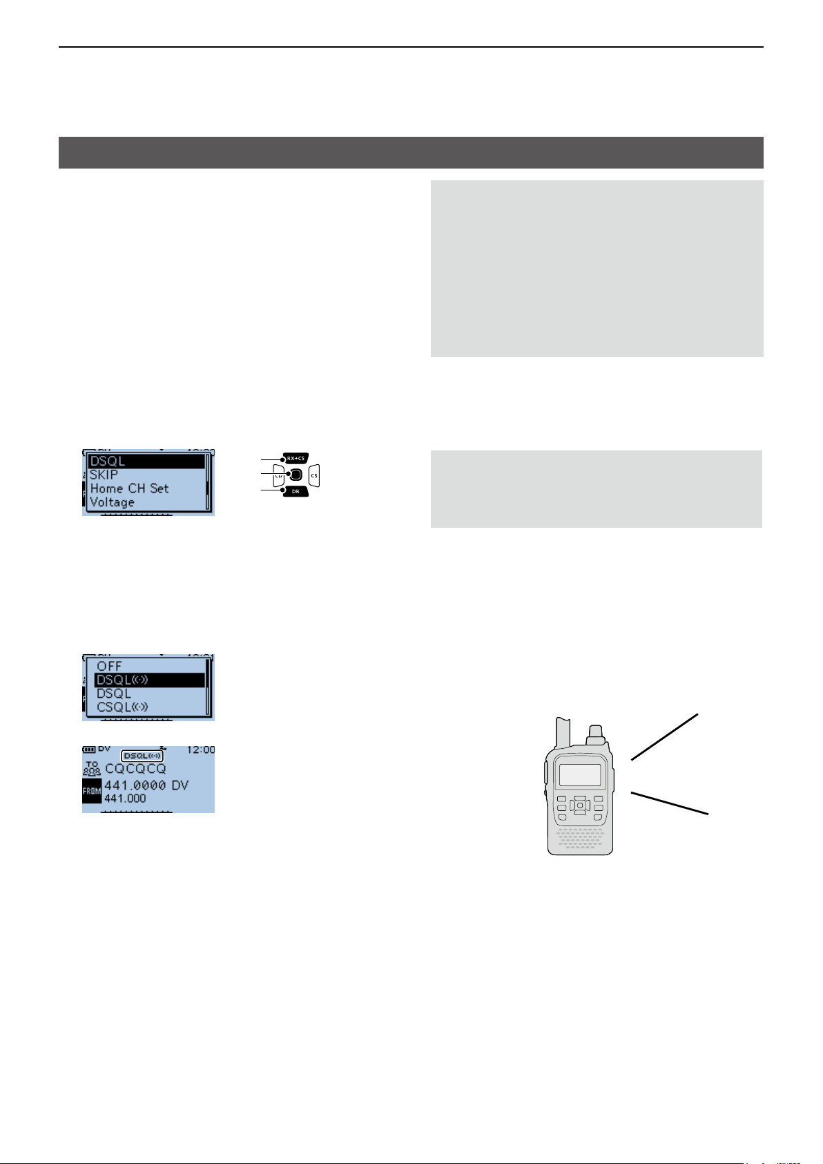
4
D-STAR OPERATION
Digital squelch functions
The digital squelch opens only when you receive a
signal addressed to your own call sign, or a signal that
includes a matching digital code.
You can silently wait for calls from others.
You can independently set the Digital squelch function
in the VFO mode, Memory mode, Call channel mode,
or DR function.
D The Digital Call Sign squelch setting
1. Push [QUICK].
2. Select “DSQL.”
[Up]
[ENT]
[Down]
3. Select “DSQLS” or “DSQL.”
• DSQLS: Turns ON the Digital Call Sign
Squelch function with the Pocket
beep function.
L “DSQLS” is displayed.
• DSQL: Turns ON the Digital Call Sign
Squelch function.
L “DSQL” is displayed.
NOTE:
• DO NOT use the Digital Call Sign Squelch
function when communicating with 2 or more
stations, because the function opens only when
receiving a signal addressed to your own call
sign. Therefore the function can be used when
communicating with only 1 station.
• Even if the squelch is closed by the Digital Call
Sign Squelch function, you can receive data in the
DV mode.
D Digital call sign squelch function with
the Pocket beep
NOTE: Conrm “DSQLS” is selected and
displayed on the screen. Do not push any key
or rotate any control after setting. Otherwise
“DSQLS” will be canceled.
When a received signal is addressed to your own
call sign, the beeps sound for 30 seconds and “S”
blinks, and the caller's call sign is announced.. Within
30 seconds, push [PTT] to answer, or push [ENT]
to stop the beeps and turn OFF the Pocket beep
function.
• “S” disappears.
L If you make no operation for 30 seconds, the beeps
automatically stop, but “S” continues to blink to
indicate that you received a call.
▼
• When the received signal includes a matching call
sign, the squelch opens and you can hear the audio.
L When the received signal does not include a
matching call sign, the digital call sign squelch does
not open. However, the S/RF meter displays the
received signal level.
Beep, Beep, Beep...
4-29
Page 54
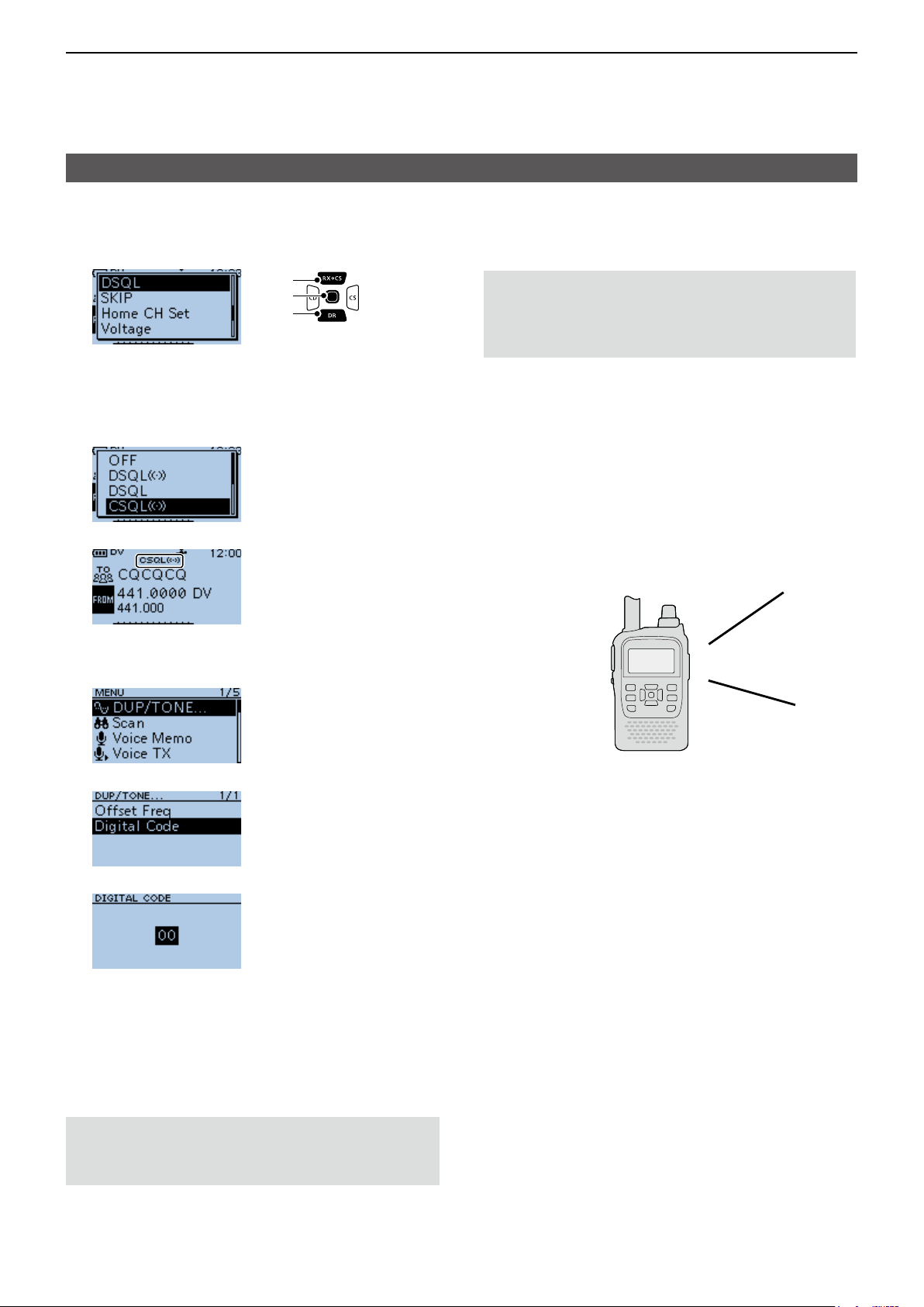
4
D-STAR OPERATION
Digital squelch functions
D The Digital Code Squelch setting
1. Push [QUICK].
2. Select “DSQL.”
[Up]
[ENT]
[Down]
3. Select “CSQLS” or “CSQL.”
• CSQLS: Turns ON the Digital Code Squelch
function with the Pocket beep.
• CSQL: Turns ON the digital code squelch
function.
▼
• “CSQLS” or “CSQL” is displayed.
4. Push [MENU].
5. Select “DUP/TONE....”
D Digital code squelch function with a
Pocket beep
NOTE: Conrm “CSQLS” is selected and
displayed on the screen. Do not push any key
or rotate any control after setting. Otherwise
“CSQLS” will be canceled.
When a received signal matches your digital code,
beeps sound for 30 seconds and “S” blinks, and
the caller's call sign is announced.
Within 30 seconds, push [PTT] to answer, or push
[ENT] to stop the beeps and turn OFF the Pocket
beep function.
• “S” disappears.
L If you make no operation for 30 seconds, the beeps
automatically stop, but “S” continues to blink to
indicate that you received a call.
Beep, Beep, Beep...
6. Select “Digital Code.”
7. Rotate [DIAL] to select a digital code.
• When the received signal includes a matching code,
the squelch opens and you can hear the audio.
L When the received signal does not include a
matching code, the digital code squelch does not
open. However, the S/RF meter displays the signal
level.
L To exit the MENU screen, push [MENU].
NOTE: Even if the squelch is closed by the Digital
Code Squelch function, you can receive data in the
DV mode.
4-30
Page 55

4
D-STAR OPERATION
Repeater list
You can save repeater information for quick and
simple communication in up to 750 repeaters
(repeater list) in up to 30 Groups.
Data must be in the repeater list to use the DR
function.
You can add and edit repeater content and groups in
the repeater list.
You can enter 4 types of frequencies into the repeater
list, as shown below:
• DV Repeater
• DV Simplex
• FM Repeater
• FM Simplex
TIP:
• For easy operation, the repeater list is preloaded
into your transceiver. However, if you do an
All Reset, the CPU deletes all setting data, the
Memory channels, and the repeater list. We
recommend that you back up the memory data to
a microSD card or save it to a PC using the
CS-31 PLUS
• The repeater list can be downloaded from the Icom
website. See D-STAR GUIDE (p. 57) in BASIC
MANUAL for details.
http://www.icom.co.jp/world/support/download/rm/index.html
cloning software.
Example: “Hirano” repeater information
D Repeater list contents
The following contents are included in the repeater list:
• TYPE: Communication type (p. 4-33)
• NAME: Repeater name (p. 4-33)
• SUB NAME: Repeater sub name (p. 4-33)
• CALL SIGN: Repeater call sign and port letter
(p. 4-33)
• GW CALL SIGN: Gateway repeater’s call sign and
port “G” (p. 4-34)
• GROUP: Repeater group (p. 4-34)
• USE(FROM): Access repeater use (p. 4-34)
• FREQUENCY: Access repeater’s frequency
(p. 4-34)
• DUP: Duplex direction (p. 4-34)
• OFFSET FREQ: Frequency offset (p. 4-34)
• MODE: Operating mode (p. 4-35)
• TONE: Tone setting (p. 4-35)
• REPEATER TONE: Repeater tone (p. 4-35)
• POSITION: Position data accuracy level
(p. 4-35)
• LATITUDE: Latitude of the repeater (p. 4-35)
• LONGITUDE: Longitude of the repeater
(p. 4-35)
• UTC OFFSET: UTC Offset (p. 4-36)
4-31
Page 56

4
D-STAR OPERATION
Entering new information into the repeater list
This section describes how to manually enter new
repeater information into the repeater list.
The required setting items differ, depending on your
communication usage. Conrm the required items, as
shown below.
NOTE: To enter repeater information into the
repeater list, the repeater’s call sign must be
entered rst.
D Required items for the communication cases
Repeater list
contents
TYPE DV Repeater DV Repeater DV Simplex FM Repeater FM Simplex
NAME
SUB NAME
CALL SIGN
GW CALL SIGN
GROUP
USE(FROM)
FREQUENCY
DUP
OFFSET FREQ
MODE N/A N/A N/A
TONE N/A N/A N/A
Used as an
access
repeater
● ●
●
(For a Gateway
call)
●
●
●
●
Used as a
destination
repeater
●
Used for DV
Simplex
N/A
N/A N/A N/A
● ● ●
● ● ●
N/A
N/A
Used as an FM
repeater
●
●
Used for FM
Simplex
N/A
N/A
N/A
REPEATER
TONE
POSITION
LATITUDE
LONGITUDE
UTC OFFSET
●: Must be entered
: Possible to enter
N/A: Not Applicable
N/A N/A N/A
4-32
Page 57
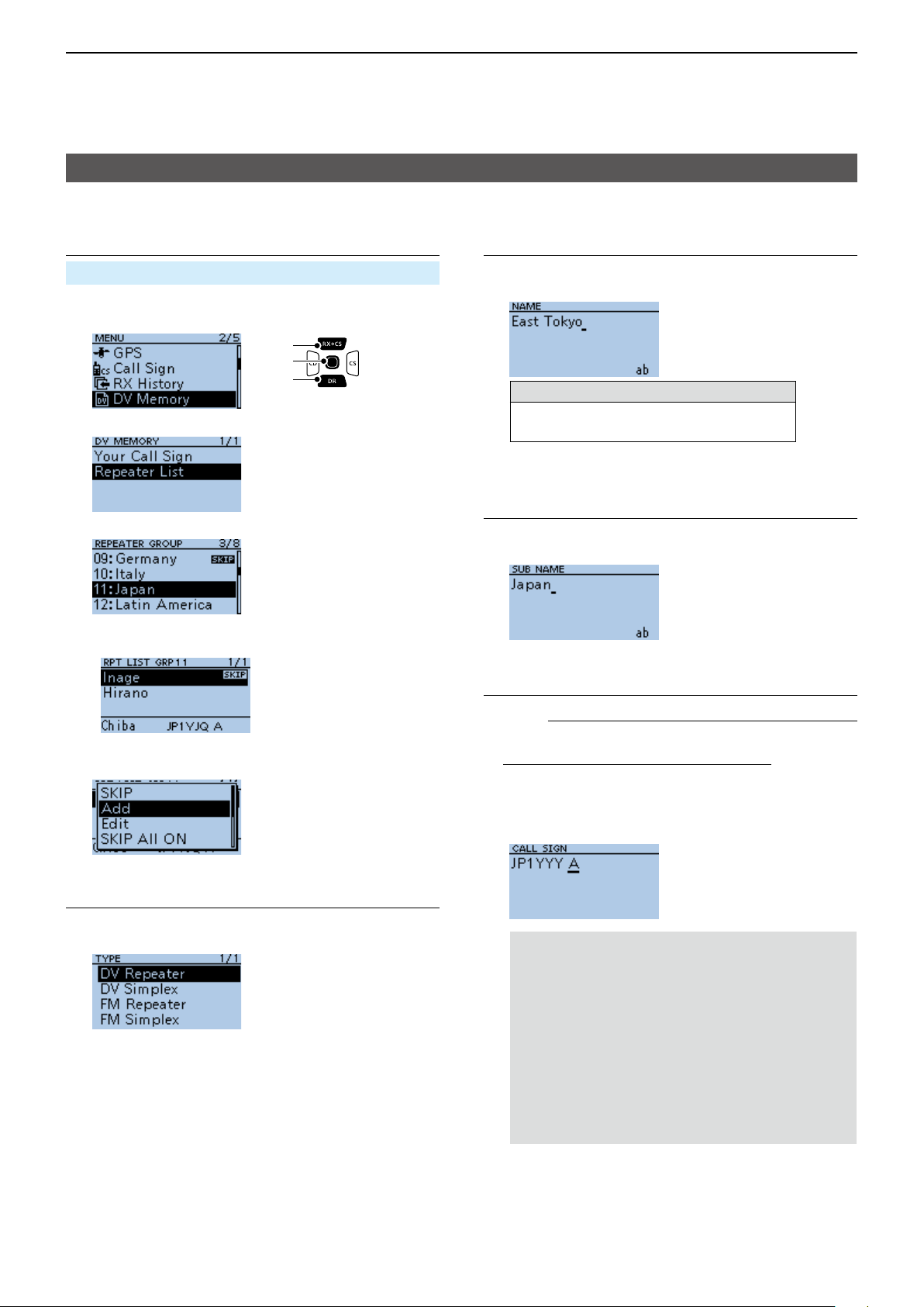
4
D-STAR OPERATION
Entering new information into the repeater list
D Entering new information into the repeater list
Step 1. Selecting the repeater group
MENU > DV Memory > Repeater List
1. Push [MENU].
2. Select “DV Memory.”
[Up]
[ENT]
[Down]
3. Select “Repeater List.”
4. Select a repeater group to add a repeater to.
(Example: 11: Japan)
• Displays the repeater list of the selected repeater
group.
5. Push [QUICK].
6. Select “Add.”
Step 3. Entering the repeater name
1. Select “NAME.”
2. Enter a name of up to 16 characters.
Selectable characters and symbols
A to Z, a to z, 0 to 9, ! " # $ % & ’ ( ) * +
, - . / : ; < = > ? @ [ \ ] ^ _ ` { | } ˜ (space)
L See page iii on how to enter characters.
3. After entering, push [ENT].
Step 4. Entering the repeater sub name
1. Select “SUB NAME.”
2. Enter a sub name of up to 8 characters.
3. After entering, push [ENT].
Step 5. Entering the repeater call sign
L When Step 2. Selecting the communication type
is set to “DV Simplex” or “FM Simplex,” go to
Step 7. Changing the repeater group.
• The REPEATER LIST EDIT screen is displayed.
Step 2. Selecting the communication type
1. Select “TYPE.”
2. Select the communication type.
• DV Repeater: Repeater operation in the DV mode.
• DV Simplex: Simplex operation in the DV mode.
• FM Repeater: Repeater operation in the FM mode.
• FM Simplex: Simplex operation in the FM mode.
1. Select “CALL SIGN.”
2. Enter the repeater call sign of up to 8 characters,
including spaces and the node letter.
NOTE: BE SURE to add the repeater node
letter in the 8th digit of the call sign, according
to the frequency band shown below. Note that
there are almost always different node letters
between Japanese D-STAR repeaters and
repeaters in other countries.
Cross band operation between different nodes
at the same repeater site can be made.
• 1200 MHz: A (B in Japan)
• 430 MHz: B (A in Japan)
• 144 MHz: C (no D-STAR repeaters in Japan)
3. After entering, push [ENT].
► Continued on the next page
4-33
Page 58

4
D-STAR OPERATION
Entering new information into the repeater list
D Entering new information into the repeater list
Step 6. Entering the gateway repeater call sign
L This item is displayed when Step 2. Selecting the
communication type is set to “DV Repeater.”
L The 8th digit in the call sign, entered in Step 5.
Entering the repeater call sign is automatically
set to “G” as the gateway port, so you can skip this
setting and go to the next item.
1. Select “GW CALL SIGN.”
2. Enter a gateway repeater call sign
of up to 8 characters, including
[Up]
[ENT]
[Down]
spaces.
L Only a space or “G” can be entered in the 8th digit.
3. After entering, push [ENT].
Step 7. Changing the repeater group
L The repeater group that is selected in Step 1.
Selecting the repeater group is displayed. You
can skip this setting and go to the next item. To
change the group, follow the steps, described
below.
1. Select “GROUP.”
2. Select the repeater group. (01 ~ 30)
Step 8. Setting “USE(FROM)” to be used as an
Access repeater
L You can use the entered repeaters as an access
repeater when using the DR function. When not
using as an access repeater, select “NO,” and go
to Step 15. Selecting the position data accuracy
level. In that case, the entered repeater is not
displayed in “FROM” on the DR screen.
Step 9. Entering the access repeater frequency
1. Select “FREQUENCY.”
2. Rotate [DIAL] to enter the repeater frequency.
L Push [CD] or [CS] to move the cursor.
3. After entering, push [ENT].
Step 10. Selecting the Duplex direction
L When Step 2. Selecting the communication type
is set to “DV Simplex” or “FM Simplex,” this item is
not displayed.
L “DUP–” is automatically set when the access
repeater frequency is entered in Step 9. Entering
the access repeater frequency. If necessary, you
can change the Duplex direction.
1. Select “DUP.”
2. Select a Duplex direction.
• OFF: Turn the duplex function OFF.
• DUP–: The transmit frequency shifts down from the
receive frequency by the offset amount.
• DUP+: The transmit frequency shifts up from the
receive frequency by the offset amount.
Step 11. Entering the frequency offset
L When Step 2. Selecting the communication type
is set to “DV Simplex” or “FM Simplex,” this item is
not displayed.
L The offset value* is automatically set when the
access repeater frequency is entered in Step
9. Entering the access repeater frequency. If
necessary, you can change the frequency offset.
* The default value differs, depending on the transceiver
version.
1. Select “OFFSET FREQ.”
2. Rotate [DIAL] to enter the frequency offset
(0.000.00 ~ 59.995.00 MHz).
1. Select “USE(FROM).”
2. Select “YES” to use the repeater as an access
repeater.
L Push [CD] or [CS] to move the cursor.
3. After entering, push [ENT].
► Continued on the next page
4-34
Page 59
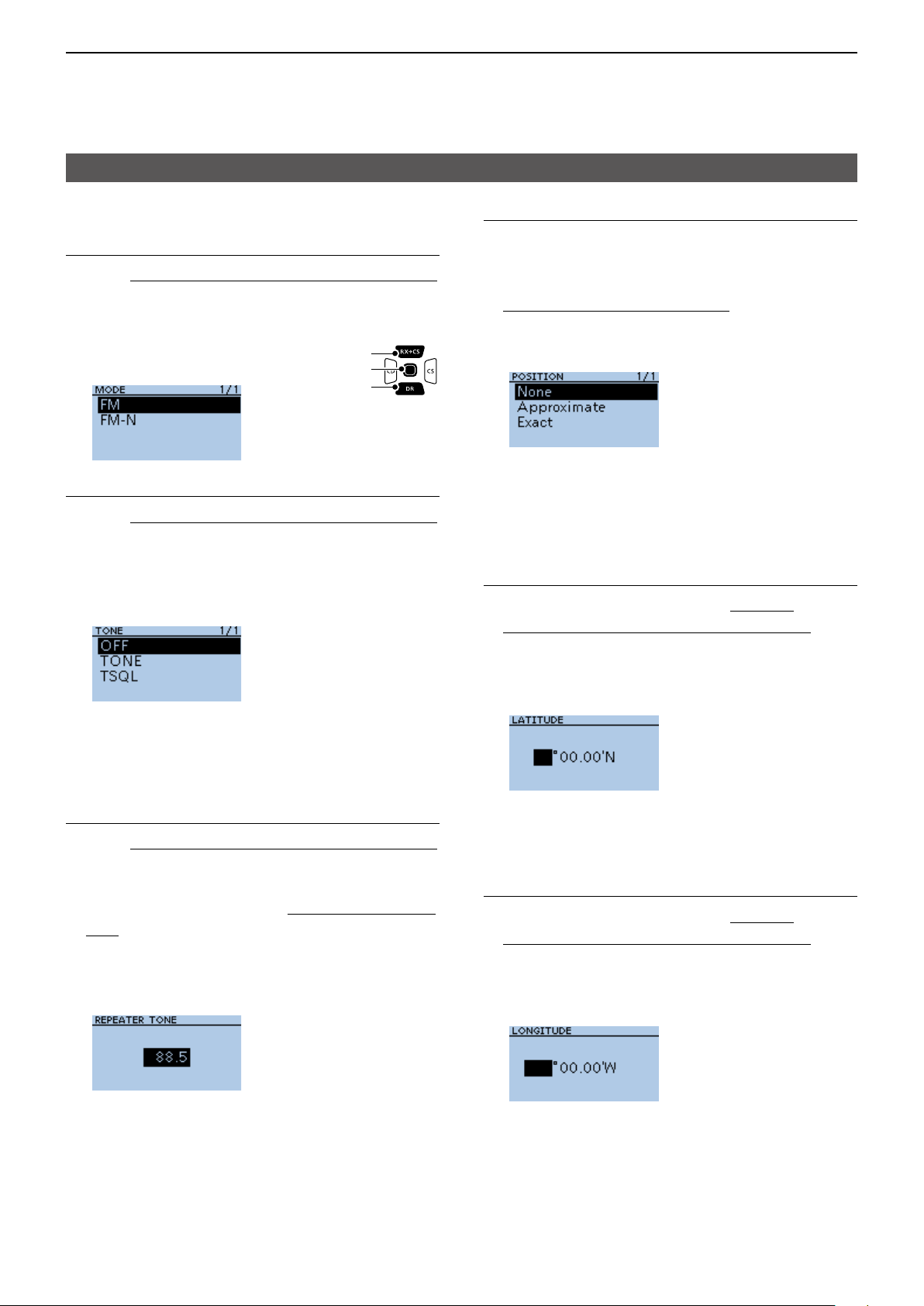
4
D-STAR OPERATION
Entering new information into the repeater list
D Entering new information into the repeater list
Step 12. Setting the FM mode
L When Step 2. Selecting the communication type
is set to “DV Repeater” or “DV Simplex,” this item is
not displayed.
1. Select “MODE.”
2. Select “FM” or “FM-N.”
[Up]
[ENT]
[Down]
Step 13. Setting the tone
L When Step 2. Selecting the communication type
is set to “DV Repeater” or “DV Simplex,” this item is
not displayed.
1. Select “TONE.”
2. Select an option.
Step 15. Selecting the position data accuracy level
L When the Near Repeater Search function is not
used, or the distance between your position and
a repeater is not needed, select “OFF,” and go to
Step 18. Setting the UTC offset.
1. Select “POSITION.”
2. Select the position data accuracy level.
• None: Select when the repeater has no position
data.
• Approximate: Select when the entered position data is
approximate.
• Exact: Select when the entered position data is
exactly correct.
Step 16. Entering the latitude
L This item is displayed only when Step 15.
Selecting the position data accuracy level is set
to “Approximate” or “Exact.”
• OFF: Turn OFF the Tone function.
• TONE: Select when the repeater requires an access
tone.
• TSQL: Select when you want to use the tone squelch
operation in simplex.
Step 14. Selecting the repeater tone frequency
L When Step 2. Selecting the communication type
is set to “DV Repeater” or “DV Simplex,” this item is
not displayed.
L This setting is required when Step 13. Setting the
tone is set to “TONE” or “TSQL.”
1. Select “REPEATER TONE.”
2. Rotate [DIAL] to select the repeater tone
frequency, then push [ENT].
1. Select “LATITUDE.”
2. Rotate [DIAL] to enter the latitude.
L Push [CD] or [CS] to move the cursor.
L To enter a north latitude, select “N,” and to enter a
south latitude, select “S.”
3. After entering, push [ENT].
Step 17. Entering the longitude
L This item is displayed only when Step 15.
Selecting the position data accuracy level is set
to “Approximate” or “Exact.”
1. Select “LONGITUDE.”
2. Rotate [DIAL] to enter the longitude.
L Push [CD] or [CS] to move the cursor.
L To enter an east latitude longitude, select “E,” and to
enter a west longitude, select “W.”
3. After entering, push [ENT].
4-35
► Continued on the next page
Page 60

4
D-STAR OPERATION
Entering new information into the repeater list
D Entering new information into the repeater list
Step 18. Setting the UTC offset
L Universal Time Coordinated (UTC) offset is the
time difference between UTC and repeater local
time. This is a useful function to know the local time
of the destination repeater before you make a call.
(p. 4-13)
1. Select “UTC OFFSET.”
2. Rotate [DIAL] to set the time
difference between UTC and the
[Up]
[ENT]
[Down]
local time, then push [ENT].
Step 19. Saving the repeater list
1. Select “<<Add Write>>.”
• The conrmation dialog is displayed.
2. Select <YES>.
• The entered contents are saved to the repeater list,
and the display returns to the selected repeater group
screen.
TIP: To cancel the entered data
1. Push [CLR] to display the “Cancel edit?”
window.
2. Select <YES>.
• Cancels entry and returns to the selected repeater
group screen.
4-36
Page 61

4
D-STAR OPERATION
Repeater list operation
D Editing repeater data
You can edit repeater data. This is useful when
already-entered data is incorrect, has changed, or
some data needs to be added to the list.
MENU > DV Memory > Repeater List
1. Push [MENU].
2. Select “DV Memory.”
[Up]
[ENT]
[Down]
3. Select “Repeater List.”
4. Select a repeater group where the repeater you
want to edit is listed.
(Example: 11: Japan)
5. Select a repeater you want to edit, then push
[QUICK].
6. Select “Edit.”
D Deleting repeater data
MENU > DV Memory > Repeater List
1. Push [MENU].
2. Select “DV Memory.”
[Up]
[ENT]
[Down]
3. Select “Repeater List.”
4. Select a repeater group where the repeater you
want to delete is listed
(Example: 11: Japan)
5. Select the repeater to be deleted, then push
[QUICK].
6. Select “Delete.”
7. Select an item, then edit it.
L See pages 4-33 ~ 4-36 for details.
8. After editing, select “<<Overwrite>>.”
• The conrmation dialog is displayed.
9. Select <YES>.
• The edited contents are saved to the repeater list, and
returns to the selected repeater group screen.
L To exit the MENU screen, push [MENU].
• The conrmation dialog is displayed.
7. Select <YES>.
• The selected repeater contents are deleted from the
repeater list, and returns to the selected repeater
group screen.
L To exit the MENU screen, push [MENU].
NOTE: The currently selected repeater on the
DR screen cannot be edited or deleted. To edit or
delete the repeater, select another repeater on the
DR screen.
4-37
Page 62

4
D-STAR OPERATION
Repeater list operations
D Rearranging the display order of the
repeaters
You can move the entered repeaters to rearrange their
display order in the selected repeater group.
MENU > DV Memory > Repeater List
Example: Moving “Decatur” above “Lake County.”
1. Push [MENU].
2. Select “DV Memory.”
3. Select “Repeater List.”
[Up]
[ENT]
[Down]
4. Select a repeater group where the repeater you
want to move is listed.
5. Select the repeater to be moved.
L Do not push [ENT].
D Adding a new repeater information from
RX History
1. Hold down [CD] for 1 second.
• The RX HISTORY screen is displayed.
2. Push [Up] or [Down] to display the repeater you
want to add to the repeater list, then push [ENT].
• Displays the RX history detail screen.
3. Push [Up] or [Down] to display “RXRPT1” and
“RXRPT2.”
4. Push [QUICK].
5. Select “Add To RPT List.”
6. Select the repeater call sign that you want to add
to the repeater list.
6. Push [QUICK].
7. Select “Move.”
8. Select the position to insert the repeater you want
to move the repeater above.
Blinks
L While moving, “DESTINATION” blinks at the top left
of the screen.
▼
• The selected repeater is inserted above the
destination repeater name.
L If “<<Move End>>” is selected, the repeater is moved
to the bottom of the group.
L To exit the MENU screen, push [MENU].
• Displays the REPEATER LIST EDIT screen. The
selected repeater call sign is automatically entered.
L If the selected repeater is already in the repeater list,
“Duplicate Call Sign” is displayed.
L See pages 4-33 ~ 4-36 to edit the contents.
7. Select “<<Add Write>>.”
• The conrmation dialog is displayed.
8. Select <YES>.
• The repeater contents are added to the repeater list,
and the display returns to the RX HISTORY screen.
L To exit the RX HISTORY screen, push [MENU].
4-38
Page 63
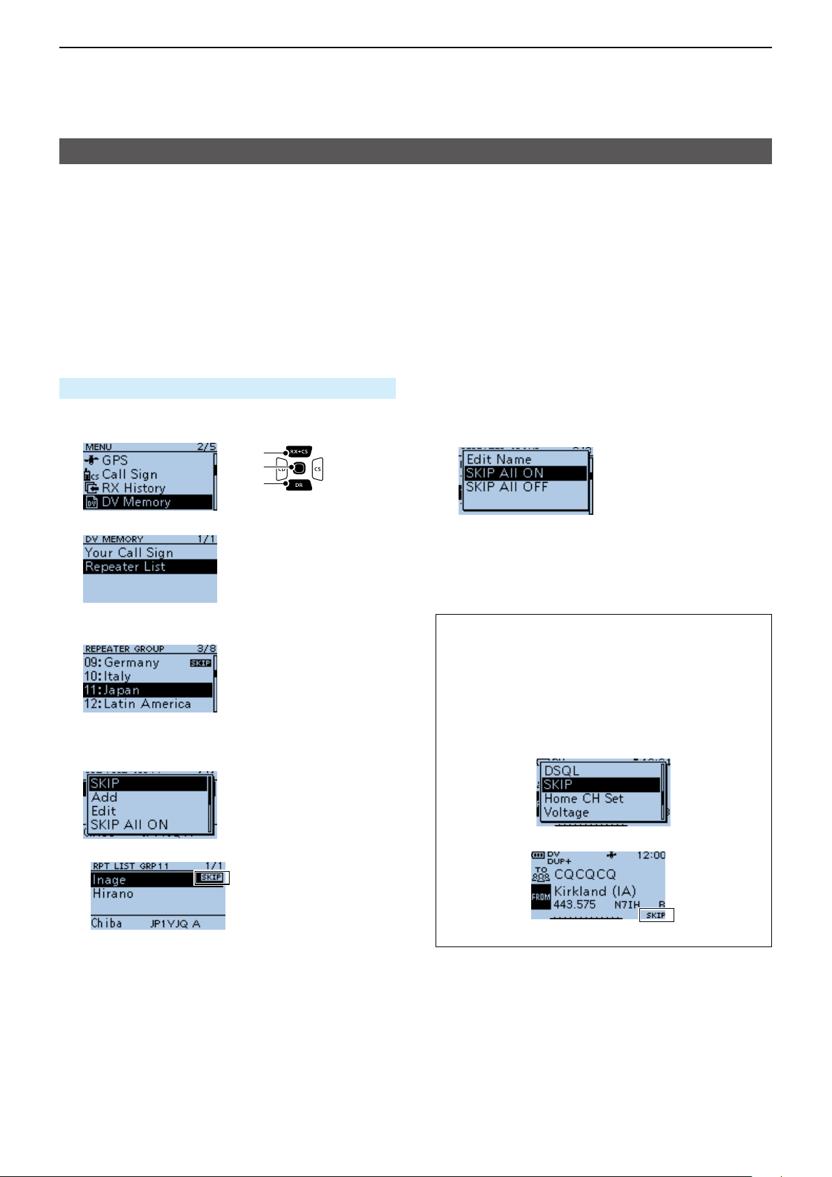
4
D-STAR OPERATION
Repeater list operations
D Skip setting for the DR scan
You can set repeaters as scan skip repeaters. The
selected repeaters are skipped for faster scanning.
You can set the skip setting to all repeaters in the
selected repeater group, or to individual repeaters.
L When a repeater is set as a skip repeater, its “USE
(FROM)” setting is automatically set to “NO.” In that
case, the repeater cannot be selected in “FROM”
(Access repeater) on the DR screen.
<Individual skip setting>
MENU > DV Memory > Repeater List
1. Push [MENU].
2. Select “DV Memory.”
[Up]
[ENT]
[Down]
3. Select “Repeater List.”
4. Select a repeater group where the repeater you
set the skip setting is listed.
(Example: 11: Japan)
5. Select the repeater to be skipped, then push
[QUICK].
6. Select “SKIP.”
<Group skip setting>
1. On the REPEATER GROUP screen, select a
repeater group, as described to the left.
2. Push [QUICK], then select “SKIP All ON” to skip
the repeaters in the group during the DR scan.
L To cancel the skip settings in the group, select “SKIP
All OFF.”
TIP:
• When you select “Repeater List” on the FROM
SELECT screen, you can set the skip setting as
described to the left.
• When “FROM” is selected on the DR screen,
push [QUICK] to set the skip setting, as shown
below.
• Displays “SKIP” by the selected repeater.
L Select “SKIP” again to cancel the skip setting.
L Select “SKIP All ON” to set the skip setting to all
repeaters in the group.
▼
L Displays “SKIP” in the “FROM” field.
4-39
Page 64
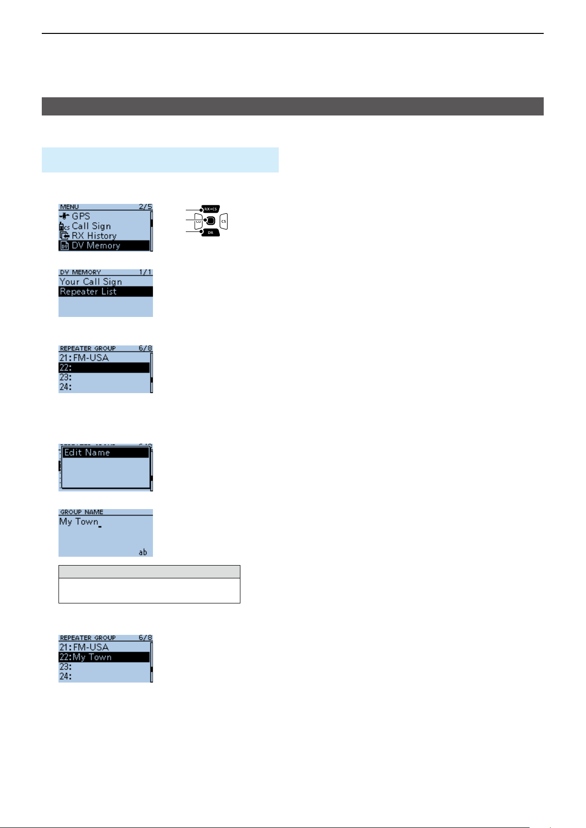
4
D-STAR OPERATION
Repeater list operations
D Entering or editing a repeater group name
MENU > DV Memory > Repeater List > Repeater
Group
1. Push [MENU].
2. Select “DV Memory.”
[Up]
[ENT]
[Down]
3. Select “Repeater List.”
4. Select a Repeater group that you edit the name.
L Do not push [ENT].
L If you select an already named group, the name is
overwritten.
5. Push [QUICK].
6. Select “Edit Name.”
7. Enter a group name of up to 16 characters.
Selectable characters and symbols
A to Z, a to z, 0 to 9, ! " # $ % & ’ ( ) * +
, - . / : ; < = > ? @ [ \ ] ^ _ ` { | } ˜ (space)
L See page iii on how to enter characters.
8. After entering [ENT].
• Sets the entered name.
L To exit the MENU screen, push [MENU].
4-40
Page 65
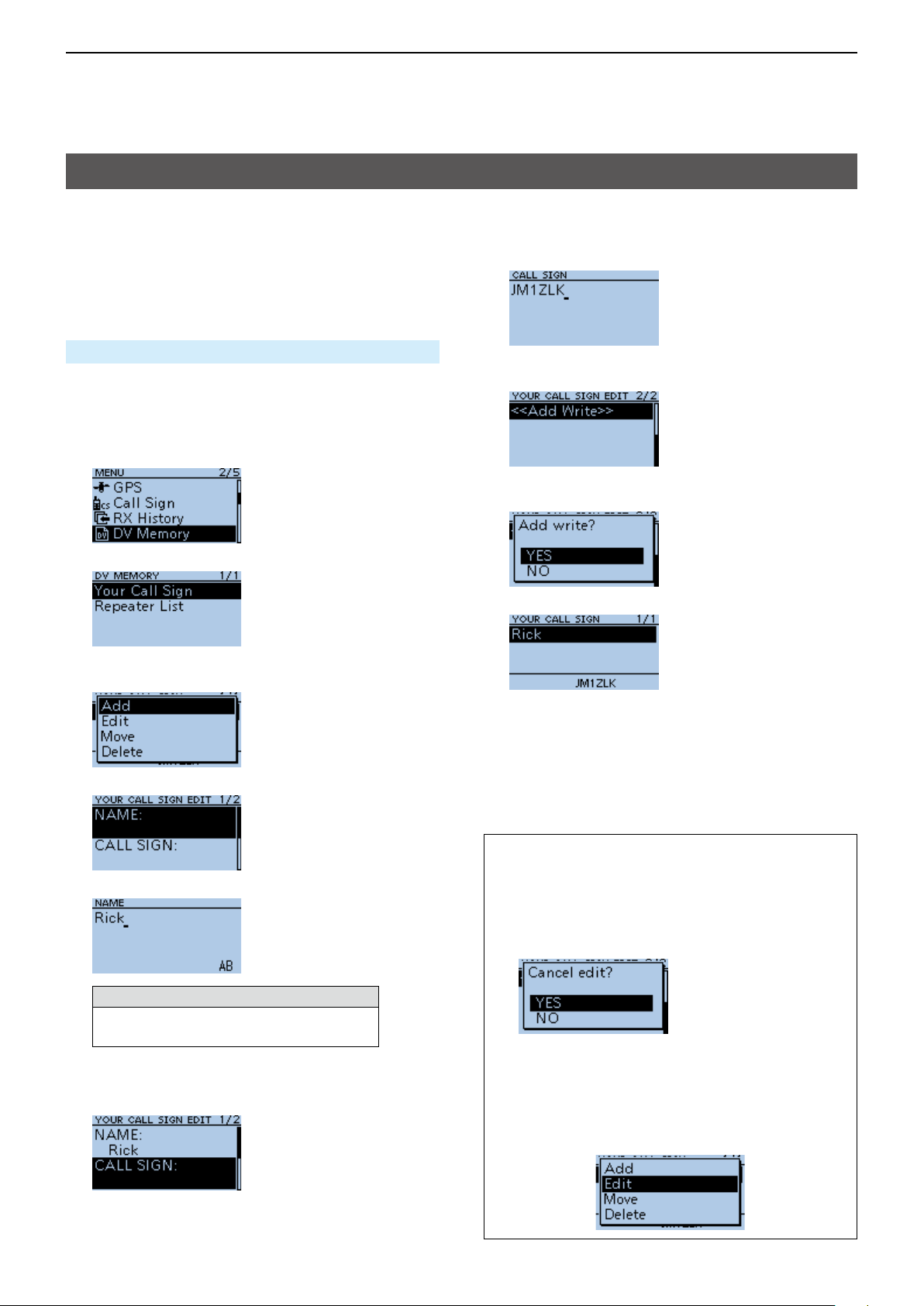
4
D-STAR OPERATION
Your Call Sign
D Entering Your Call Sign
You can manually enter a Your (destination) Call Sign.
When a Your Call Sign is set to “TO,” you can make a
call to the station, even if you do not know where the
station is currently located.
Up to 200 “Your Call Signs” can be entered.
10. Enter Your call sign of up to 8 characters,
including spaces.
(Example: JM1ZLK)
MENU > DV Memory > Your Call Sign
Example: Entering “Rick/JM1ZLK” to the Your Call
Sign memory.
1. Push [MENU].
2. Select “DV Memory.”
3. Select “Your Call Sign.”
4. Push [QUICK] on the YOUR CALL SIGN screen.
5. Select “Add.”
6. Select “NAME.”
11. After entering, push [ENT].
12. Select “<<Add Write>>.”
• The conrmation dialog is displayed.
13. Select <YES>.
▼
• “Rick JM1ZLK” is entered into the Your Call Sign
memory.
L To exit the MENU screen, push [MENU].
7. Enter a station name of up to 16 characters.
(Example: Rick)
Selectable characters and symbols
A to Z, a to z, 0 to 9, ! " # $ % & ’ ( ) * +
, - . / : ; < = > ? @ [ \ ] ^ _ ` { | } ˜ (space)
L See page iii on how to enter characters.
8. After entering, push [ENT].
9. Select “CALL SIGN.”
TIP:
To cancel the entered call sign
1. Push [CLR] to display the “Cancel edit?”
window.
2. Select “YES” to cancel the entry and return to
the YOUR CALL SIGN screen.
To edit the entered call sign
To edit the entered call sign, select “Edit” in step 5.
This is useful when already-entered data is
incorrect, has changed, or some data needs to be
added to the list.
4-41
Page 66

4
D-STAR OPERATION
Your Call Sign
D Deleting Your Call Sign
MENU > DV Memory > Your Call Sign
1. Push [MENU].
2. Select “DV Memory.”
[Up]
[ENT]
[Down]
3. Select “Your Call Sign.”
4. Select a call sign you want to delete.
L Do not push [ENT].
5. Push [QUICK].
6. Select “Delete.”
D Rearranging the display order of Your
Call Signs
You can move Your Call Signs to rearrange their
display order.
If the stations you often communicate with are moved
to the top of the list, it is easy to nd them.
MENU > DV Memory > Your Call Sign
Example: Moving “Rick” above “Eddy.”
1. Push [MENU].
2. Select “DV Memory.”
3. Select “Your Call Sign.”
[Up]
[ENT]
[Down]
4. Select a Your Call Sign to be moved.
L Do not push [ENT].
• A conrmation dialog is displayed.
7. Select <YES>.
▼
• The selected call sign is deleted from the Your Call
Sign list, and the returns to the YOUR CALL SIGN
screen.
L To exit the MENU screen, push [MENU].
NOTE: The currently selected Your Call Sign on the
DR screen cannot be edited or deleted. To edit or
delete the Your Call Sign, select another Your Call
Sign on the DR screen.
5. Push [QUICK].
6. Select “Move.”
7. Select the position to insert the Your Call Sign you
want to move the call sign above.
Blinks
L While moving, “DESTINATION” blinks.
▼
• The selected call sign is inserted above the destination
call sign.
L If “<<Move End>>” is selected, the Your Call Sign is
moved to the bottom of the group.
L To exit the MENU screen, push [MENU].
4-42
Page 67

4
D-STAR OPERATION
Are your settings correct?
If you make a Local Area call with a gateway setting
still selected in “TO,” the destination repeater will be
busy while you transmit.
The stations that want to use the repeater as their
Access repeater cannot access it, as shown below.
BE SURE to set CQCQCQ in “TO” on the DR screen
when you intend to make a Local Area call, or after
you nish a Gateway call.
Example: JG3LUK wants to make a Local Area call.
CQ D-STAR Hirano, this is JG3LUK
CQ D-STAR Hirano, this is JG3LUK
through JP3YHH port A for a Local call...
through JP3YHH port A for a Local call...
Hirano repeater Hamacho repeater
Caller
(JG3LUK)
CQ D-STAR Hirano, this is
CQ D-STAR Hirano, this is
JG3LUK through JP3YHH port A
JG3LUK through JP3YHH port A
for a Local call...
for a Local call...
Hirano area Hamacho area
JG3LUK’s setting
The destination (“TO”) setting is incorrect.
His setting is wrong!
His setting is wrong!
I can’t access the repeater!
I can’t access the repeater!
INTERNETINTERNET
CQ D-STAR Hirano, this is
CQ D-STAR Hirano, this is
JG3LUK through JP3YHH port A
JG3LUK through JP3YHH port A
for a Local call...
for a Local call...
Called
NOTE: With this setting, you can make a Local
Area call, but the destination Repeater, selected in
“TO,” is also busy while you transmit.
The stations that want to use the repeater as their
Access Repeater cannot access it.
Correct setting
To make a Local Area call, set the
destination (“TO”) to “CQCQCQ.”
See page 4-9 for details.
4-43
Page 68

Section 5
GPS OPERATION
GPS operation features ��������������������������������������������������������������������������5-2
Before starting GPS operation����������������������������������������������������������������5-3
D Conrming the GPS signal receiving ����������������������������������������������5-3
GPS TX mode and TX format types �������������������������������������������������������5-4
Difference between older models �����������������������������������������������������������5-4
Checking your position ���������������������������������������������������������������������������5-5
D Displaying Position Data ����������������������������������������������������������������� 5-5
D GPS POSITION screens and their meanings ��������������������������������� 5-6
D About the RX screen ����������������������������������������������������������������������� 5-7
D About the Grid Locator �������������������������������������������������������������������� 5-8
D Displaying the Grid Locator ������������������������������������������������������������5-8
D About the Course ��������������������������������������������������������������������������� 5-8
D Changing the GPS Memory or Alarm ���������������������������������������������5-8
D Changing the Compass Direction ���������������������������������������������������5-9
D Saving your own or a received station’s position ����������������������������5-9
Checking GPS information (Sky view screen) ��������������������������������������5-10
D About the display ��������������������������������������������������������������������������5-10
D Meaning of each icon �������������������������������������������������������������������� 5-10
Transmitting D-PRS data ����������������������������������������������������������������������5-11
D D-PRS ������������������������������������������������������������������������������������������� 5-11
D Operating in the D-PRS mode ������������������������������������������������������ 5-11
D Setting D-PRS Position (Mobile) ��������������������������������������������������� 5-12
D About each setting item ����������������������������������������������������������������5-13
D Displaying your position using a mapping software ���������������������� 5-16
Transmitting NMEA data �����������������������������������������������������������������������5-18
D Setting the GPS data sentence ����������������������������������������������������5-18
D Entering a GPS message �������������������������������������������������������������5-19
GPS Automatic Transmission ���������������������������������������������������������������5-19
GPS Memory ����������������������������������������������������������������������������������������5-20
D Adding a GPS Memory �����������������������������������������������������������������5-20
D Entering the GPS Memory group name ���������������������������������������� 5-23
D Deleting GPS Memory ������������������������������������������������������������������5-23
D Rearranging the display order of the GPS data ���������������������������� 5-24
GPS Alarm ��������������������������������������������������������������������������������������������5-25
D Setting the GPS Alarm function to All Memories (all GPS Memories)
������������������������������������������������������������������������������������������������������5-26
D Setting the GPS Alarm function to RX
(a caller station) ����������������������������������������������������������������������������5-27
GPS Logger function ����������������������������������������������������������������������������5-28
D GPS Logger operating outline ������������������������������������������������������5-28
D Conrming the GPS Logger function ��������������������������������������������5-28
D Setting the GPS record interval ����������������������������������������������������5-28
D Setting the GPS record sentence �������������������������������������������������5-29
D Viewing the log data on a PC Map������������������������������������������������5-30
D The <<GPS Logger Only>> mode ������������������������������������������������5-32
D <<GPS Logger Only>> outline ������������������������������������������������������ 5-32
D Setting the <<GPS Logger Only>> mode ������������������������������������� 5-32
5-1
Page 69

5
GPS OPERATION
GPS operation features
D-PRS Extension function (p. 5-4)
The D-PRS Extension function enables you to receive Object, Item, and Weather information in addition to Position
data. With this extension, you can simultaneously receive earthquake information, trafc accident information,
emergency information, or weather information, and so on, along with voice audio in the DV mode.
GPS Memory (p. 5-20)
You can enter up to 200 GPS Memories in the transceiver. By adding destination position information in a GPS
Memory, you can effectively use the GPS Alarm function. The position information that you acquired can also be
entered in a GPS Memory.
Editing GPS Memories using
Editing GPS Memories using
a PC is easier than using
I can enter the location information
I can enter the location information
of the mountain I’m going to hike!
of the mountain I’m going to hike!
a PC is easier than using
the transceiver!
the transceiver!
GPS Alarm function (p. 5-25)
When a target station comes into the set alarm area, or when you approach an entered GPS Memory position, the
function can sound an alarm. With this function, you can know that you are approaching the destination.
GOAL!GOAL!
I’m almost there!I’m almost there!
GPS Logger function (p. 5-28)
The GPS Logger function enables you to save the position data from a GPS receiver into a microSD card as a log.
If you use this GPS Logger while driving, you can check your driving history on a mapping software program.
I can track my GPS log in a
I can track my GPS log in a
mapping software program.
mapping software program.
This is how I traveled...interesting!
This is how I traveled...interesting!
5-2
Page 70
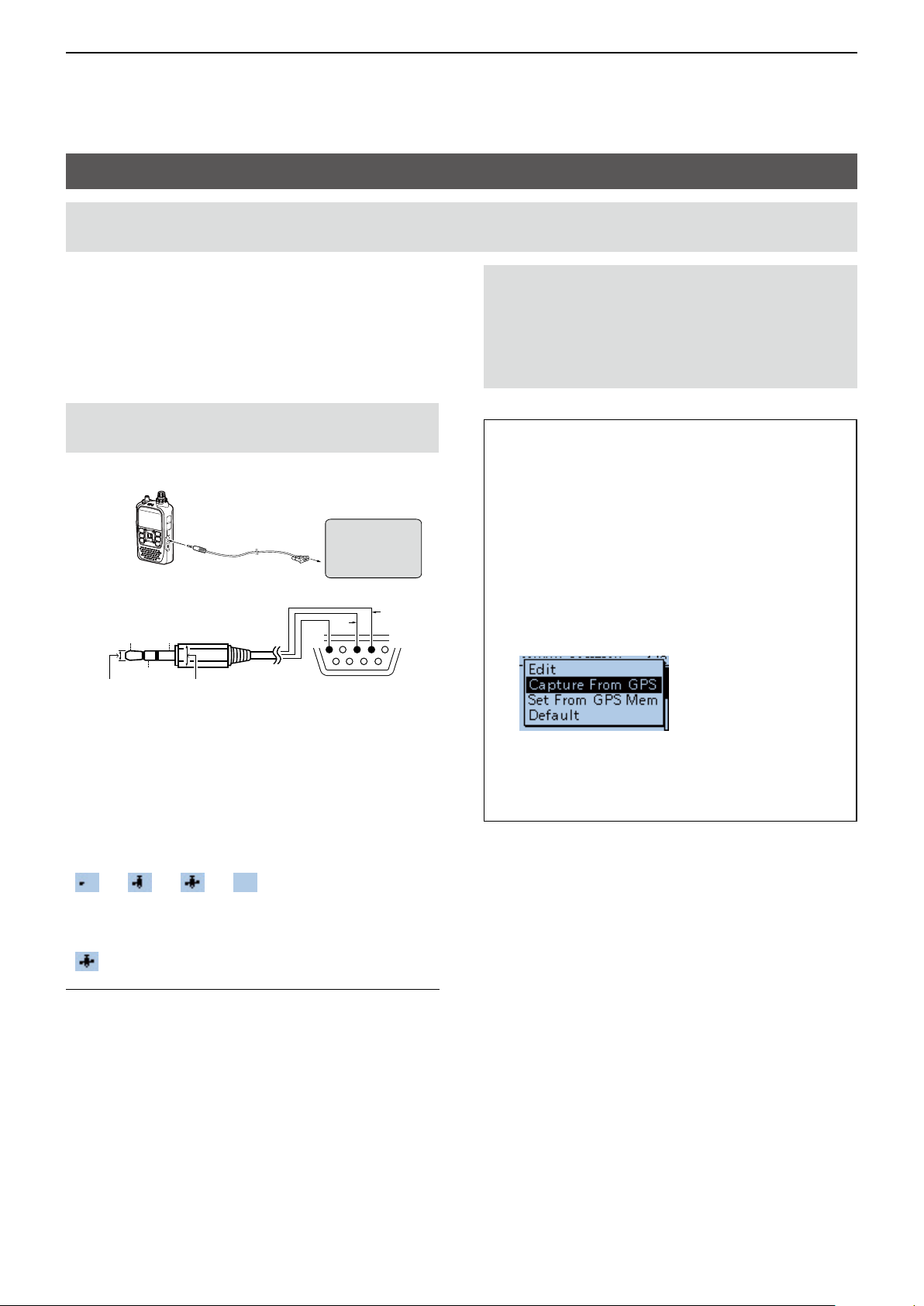
5
GPS OPERATION
Before starting GPS operation
NOTE: Before using the GPS function, read “IMPORTANT NOTES” about the GPS receiver in BASIC MANUAL
page vi.
The transceiver has a built-in internal GPS receiver.
The GPS receiver’s position data can be received in
any mode. Also, a NMEA format compatible external
GPS receiver can be connected to the transceiver
through the [DATA] jack.
To receive signals from an external GPS receiver,
connect it to the transceiver as shown below.
NOTE: Transmit or receive position data can be
transmitted in only the DV mode.
Connection
TxD
2.5 mm
(0.1 in) (d)
To the
[DATA] jack
GND
RxD
less than 6.0 mm
(0.2 in) (d)
cable
To the
RS-232C port
5
GPS
Receiver
(Third party)
3
2
1
69
NOTE: Continuously using the Internal GPS
mode causes the transceiver’s battery to quickly
be exhausted. Turn ON the Power Save mode if
needed. See page 11-9 for details.
( MENU > GPS > GPS Set > Power Save (Internal
GPS))
TIP: To prolong the battery life in the GPS mode
To prolong the battery life while operating in the
GPS mode, manually update your position with the
received GPS data.
1� Set GPS Select to “Internal GPS,” and receive
your position from the internal GPS receiver.
(MENU > GPS > GPS Set > GPS Select)
2� Open the MANUAL POSITION screen, and
then push [QUICK] .
(MENU > GPS > GPS Set> Manual Position)
3� Select “Capture From GPS.”
• Connect Pin 2 to RxD (Ring).
• Connect Pin 3 to TxD (Tip).
• Connect Pin 5 to GND (Sleeve).
D Con rming the GPS signal receiving
Con rm the GPS receiver is receiving satellite signals.
The GPS icon blinks when searching for satellites.
→ → →
The GPS icon stops blinking when the minimum
number of satellites needed are found.
InformationL
• It may take only a few seconds to receive, or it may
take a few minutes, depending on your operating
environment. If you have dif culties receiving, we
recommend that you try a different position.
• When GPS Select is set to “Manual,” the icon is not
displayed. When using a third party GPS receiver,
set to “External GPS.”
(MENU > GPS > GPS Set > GPS Select)
• Set GPS Indicator to “ON” to display the GPS icon.
(MENU > GPS > GPS Set > GPS Indicator)
• Your current position is now memorized and
displayed on the MANUAL POSITION screen.
4� Set GPS Select to “Manual.”
(MENU > GPS > GPS Set > GPS Select)
5-3
Page 71

5
GPS OPERATION
GPS TX mode and TX format types
GPS position data has 2 TX modes, D-PRS and
NMEA. Moreover, with the D-PRS mode data, 5
position formats. Position (Mobile station/Base
station), Object, Item, and Weather, are selectable.
Example: When the caller’s TX format is D-PRS Position (Mobile)
D-PRS D-PRS is a function that simultaneously sends position data received from the
internal or external GPS receiver, using the slow speed data packet space, along
with voice.
Position (Mobile) A station operating from a vehicle, or other position, away from it's normal base
position�
Position (Base)* A station operating at home or in a building.
Object* Transmitting Object data such as an earthquake information, satellite track
information, and so on.
An Object contains a time stamp.
Item* Transmitting Item data such as a trafc accident, lighthouse, antenna, or DV
access point position, and so on.
An Item does not contain a time stamp.
Weather* A station transmitting weather information received from a weather device.
NMEA A station transmitting position data (NMEA0183) received from the internal or an
external GPS receiver.
* You can receive, but cannot transmit this format with the ID-31A PLUS or ID-31E PLUS.
Difference between older models
(As of November 2017)
• The GPS TX mode, “GPS (DV-G)” and “GPS-A (DV-A),” are now called as “NMEA (DV-G)” and “D-PRS (DV-A).”
GPS (DV-G) → NMEA (DV-G)
GPS-A (DV-A) → D-PRS (DV-A)
• For users who have one of the following models:
( ID-800H, IC-91AD/E91, IC-U82, IC-V82, IC-7100, ID-51A/E, ID-31A/E, IC-9100, IC-80AD/E80D, ID-880H/E880,
IC-92AD/E92D, IC-2820H/E2820)
When you receive a D-PRS position (Base), Object, Item, or Weather information, their data is not displayed.
• Only the ID-51A/E PLUS, ID-51A/E PLUS2, ID-31A/E PLUS, ID-5100A/E, and ID-4100A/E, can receive Power,
Height, Gain, and Directivity data.
• For users who have one of the following models:
(IC-9100, IC-80AD, IC-E80D, ID-880H, ID-E880, IC-92AD, ICE92D, IC-U82, IC-V82)
If you transmit with the Altitude setting ON, the character string is included in a comment on the products that
cannot display the altitude.
• Set the GSV sentence to OFF when sending the GPS message to conventional digital transceivers (IC-2820H,
IC-E2820, ID-800H, IC- 91AD, IC-E91, IC-V82, IC-U82, IC-2200H). The GSV sentence is incompatible with them.
They will not display GPS messages properly if sent as a GSV sentence from the ID-31A/E PLUS.
5-4
Page 72

5
GPS OPERATION
Checking your position
You can check your current position.
This section is described using received position data.
L The screens are just examples.
D Displaying Position Data
1� Push [QUICK] in the standby mode.
2� Select “GPS Position.”
[Up]
[ENT]
[Down]
3� Rotate [DIAL].
• My screens (MY), received screens (RX), the GPS
Memory channel screen (MEM), and the GPS Alarm
channel screen (ALM) are displayed.
NOTE: Latitude, longitude, and altitude data may
differ, depending on your received GPS signal.
TIP:
• If you transmit with the GPS POSITION screen
open, the screen is temporarily canceled. To
check the position, push [QUICK], then select
“GPS Position” while transmitting.
• On the MY screen or RX screen, you can enter
the displayed position information in a GPS
Memory by pushing [QUICK] and selecting “GPS
Memory.”
• See page 5-20 about the GPS Memory function
and see page 5-25 about the GPS Alarm function
to know more details.
↑
The displayed icon depends on the type of
screen (MY, RX, MEM, or ALM).
L To exit the MENU screen, push [MENU].
5-5
Page 73
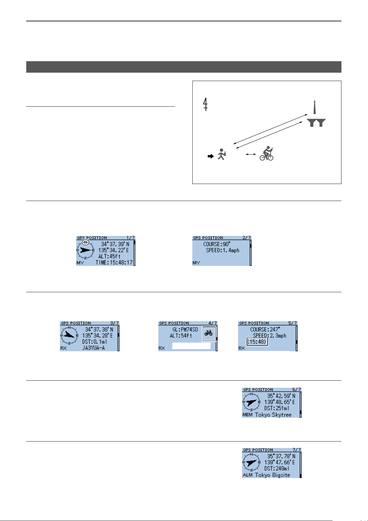
5
GPS OPERATION
Checking your position
D GPS POSITION screens and their
meanings
Example for the GPS POSITION screens:
GPS Memory:
Tokyo Skytree
InformationL
• Pushing [QUICK] to change the compass direction.
0.1 ml
251 ml
249 ml
Caller station
(D-PRS: mobile)
Course: 247 degrees
Speed: 2.3 mph
GPS Alarm:
Tokyo Big Sight
(p. 5-9)
• About the Course (p. 5-8)
• About the Grid Locator (p. 5-8)
Your station
Course: 90 degrees
Speed: 1.4 mph
MY screen (Your position information)
When GPS Select is set to “Manual,” compass heading and course direction are not displayed. (p. 11-9)
Compass direction
top is North.
↓
Your course
heading is
East.
→
←Latitude
←Longitude
←Altitude
←Course direction
←Speed
↑
Received time
RX screen (Callerʼs position information)
Depending on the callerʼs GPS TX Mode and TX format, displayed itemʼs meanings differ, and some data may not
be displayed. (p. 5-7)
Example: The caller stationʼs GPS TX Mode is “D-PRS” and its TX format is “Position (Mobile).”
← Callerʼs Course
direction
from your
position
→Direction
↑
Caller’s call sign with SSID
← Distance
from your
position
D-PRS symbol
↑
Time the caller acquired
the position data
MEM screen (GPS Memory channel’s information)
Direction from
your position
→
← Distance from
↑
1
*
your position
ALM screen (GPS Alarm Memory channel’s information)
*1 When a name is not entered in the GPS Memory
channel, date and time are displayed instead of the
name.
*2 In the Quick Menu window, you can change the
GPS Memory or GPS Alarm in the GPS POSITION
screen. (p. 5-8)
5-6
Direction from
your position
→
← Distance from
↑
2
*
your position
Page 74

5
GPS OPERATION
Checking your position
D About the RX screen
TX format:
D-PRS
Position (Mobile)
Position (Base)
Object
← For a mobile station, Course
and Speed are displayed.
Moving symbol
Base station symbol
↑
For a base station, Output power, Antenna height,
Antenna gain, and Antenna direction are displayed.
Item
Weather
L Call sign is displayed with an SSID.
L When the Object or Item’s status is nished, “KILLED” is displayed.
TX format:
NMEA
Time that the caller
sent the Object’s data.
L For an Item station,
Time is not displayed.
↑
Time that the caller acquired
the weather data.
L Symbol or SSID is not displayed when the TX format is NMEA.
5-7
Page 75

5
GPS OPERATION
Checking your position
D About the Grid Locator
Grid Locator (GL) is a position compressed into a 6
character code, calculated by the longitude and the
latitude.
The locator is simply calculated by dividing the earth
surface into squares.
It is used to nd the area of a transceiver station.
Field
PM74SO
Square Subsquare
The grid locator map of Japan
44
43
53
42
52
41
51
40
50
49
59
48
58
47
57
46
56
45
55
PM
44
54
43
53
42
52
41
51
54
64
63
62
PN
61
60
69
68
67
66
65
64
63
62
61
140°
74
84
73
83
72
82
71
81
70
80
79
89
78
88
77
87
76
86
75
85
74
84
73
83
72
82
71
81
94
04
93
03
92
02
91
90
99
98
97
96
95
94
93
92
91
14
24
13
23
12
22
QN
01 11 21
00
10
09
19
08
18
07
17
06
16
05
15
04
14
QM
03
13
02
12
01
11
20
29
28
27
40°
26
25
24
23
22
21
D About the Course
The course displayed on the GPS POSITION screens
are indicated in degrees.
315°
270°
W
225°
0°
N
S
180°
45°
E
135°
90°
D Changing the GPS Memory or Alarm
You can change the GPS Memory or GPS Alarm in
the GPS POSITION screen.
1� While selecting the MEM screen or ALM screen,
push [QUICK].
2� Select “GPS Memory Select,” or select “Alarm
Select.”
MEM screen
D Displaying the Grid Locator
You can exchange the Altitude display or the Distance
display with the Grid Locator display, depending on
the displayed GPS POSITION screen.
1� While selecting the MY screen (1st), MEM screen,
or ALM screen, push [QUICK].
2� Select “Grid Locator Display.”
• On the MY screen, the GL is displayed instead of the
altitude.
• On the MEM screen or ALM screen, the GL is
displayed instead of the distance.
L While displaying the GL, pushing [QUICK] and
selecting “Altitude Display” or “Distance Display,” to
return to the previous display.
▼
ALM screen
▼
3� Select the GPS Memory or GPS Alarm to display
on the GPS POSITION screen.
L Adding or editing a GPS Memory: p. 5-20
L Setting the GPS Alarm: pp. 5-26, 5-27
5-8
Page 76

5
GPS OPERATION
Checking your position
D Changing the Compass Direction
You can set the compass direction to Heading Up,
North Up, or South Up.
1� Push [QUICK].
2� Select “GPS Position.”
• Displays the GPS POSITION screen.
3� Push [QUICK].
4� Select “Compass Direction.”
[Up]
[ENT]
[Down]
5� Select the compass direction.
• Heading Up: The top is always your course
direction.
• North Up: The top is always north.
• South Up: The top is always south.
▼
D Saving your own or a received station’s
position
You can save position of your station and the position
of the caller station.
The GPS Memory has a total of 200 channels, and
the channels can be assigned into one of 27 banks,
A ~ Z, and (No Group).
1� Push [QUICK].
2� Select “GPS Position.”
• Displays the GPS POSITION screen.
3� Select the screen that you want to save.
[Up]
[ENT]
[Down]
L To save your own position: MY screen
L To save a received position: RX screen
4� Push [QUICK].
5� Select “Add To GPS Memory.”
Heading Up North Up South Up
L See pages 5-20 ~ 5-22 for entering details.
6� Select “<<Add Write>>.”
• The conrmation dialog is displayed.
L To select the destination group to be saved, select
“GROUP.”
7� Select <YES>.
• Saves the data in the GPS Memory, then returns to
the GPS POSITION screen.
8� Push [CLR].
• Returns to the standby screen.
TIP: The position is saved in the selected group
with the "GROUP" item.
(MENU > GPS > GPS memory)
5-9
Page 77

5
GPS OPERATION
Checking GPS information (Sky view screen)
This screen is used to view GPS satellite information
when the GPS icon does not stop blinking for a long
time.
The GPS Information displays the quantity, signal
power, and position of the GPS satellites.
The sky view screen displays the position of GPS
satellites. The screen also displays the direction,
elevation angle, satellite numbers, and their receiving
signal strength status.
1� Push [QUICK].
2� Select “GPS Information.”
• Displays the GPS INFORMATION screen.
3� Push [CLR].
• Returns to the standby screen.
D Meaning of each icon
• (): Untracking satellite.
• (01): Tracking satellite with a weak signal, shown
by the satellite number.
• (‚1): Tracking satellite with a strong signal,
shown by the satellite number.
• (SAT): The quantity of tracking satellites.
• Altitude: The altitude of your station.
The altitude is only displayed when 4 or
more satellites are tracked. When 3 or less
satellites are tracked, “------ft” is displayed.
• Longitude/Latitude:
Longitude and Latitude of your station
position�
D About the display
Sky
view
screen
Satellite
number
15’s signal
is strong�
→
North
←Tracking satellite quantity
←Altitude
←Latitude
←Longitude
← Untracking
satellite
← Satellite
number 30’s
signal is weak.
Elevation angle
0 degree line
Elevation angle
30 degree line
Elevation angle
60 degree line
Elevation angle
90 degree line
(Zenith)
The image of satellite number 15
Elevation angle 90
degree line (Zenith)
N
Satellite
number 15
W
Elevation angle
60 degree line
Elevation angle
E
30 degree line
Elevation angle
0 degree line
S
5-10
Page 78

5
GPS OPERATION
Transmitting D-PRS data
When D-PRS is selected as the GPS TX mode, you
can transmit D-PRS data.
When operating in the D-PRS mode, the following
codes are transmitted to the PC.
D-PRS code is based on APRS
®
code.
(APRS®: Automatic Packet Reporting System).
D D-PRS
D-STAR Packet Reporting System (D-PRS) is a mode
that simultaneously sends position data received from
the internal or external GPS receiver, using the slow
speed data packet space, along with voice audio in
the DV mode. In the Analog mode, you can transmit or
receive only voice audio or data at one time. However
a D-PRS capable radio can transmit or receive
message data or GPS position data at the same time
voice is being transmitted or received.
I-GATE is required to send position data to the APRS
server.
The image of D-PRS
<Using a Repeater>
Voice, Messages, and
D-PRS positions
Voice, Messages, and
D-PRS positions
<Simplex>
D-STAR Repeater
D-PRS positions
NOTE:
• If GPS select is set to “Manual,” the manually
entered position data in Manual Position is change
to the D-PRS data format to transmit.
(p. 11-9)
(MENU > GPS > GPS Set > Manual Position)
• Note that if GPS Auto TX is set to any other setting
than “OFF,” the data is transmitted according to the
set time. (p. 11-18)
(MENU > GPS > GPS Auto TX)
APRS server
Information from
an APRS network
D-PRS
positions
INTERNETINTERNET
PC
JA3YUA-Z
Voice, Messages, and
D-PRS positions
Voice, Messages, and
D-PRS positions
D Operating in the D-PRS mode
To transmit in D-PRS, follow the steps below, and
for more details, see the pages listed along with the
steps�
1� “MY” (Your own call sign) entering
(BASIC MANUAL)
2� Receiving GPS data (p. 5-3)
3� Set GPS TX mode to “D-PRS (DV-A).” (p. 5-12)
4� Set TX information (p.5-12)
L You must set SSID and Symbol�
( GPS > GPS TX Mode > D-PRS (DV-A) > SSID,
Symbol)
Complete! (You can transmit in the D-PRS mode.)
D-PRS
positions
5-11
You can check the
position on a map site!
Page 79
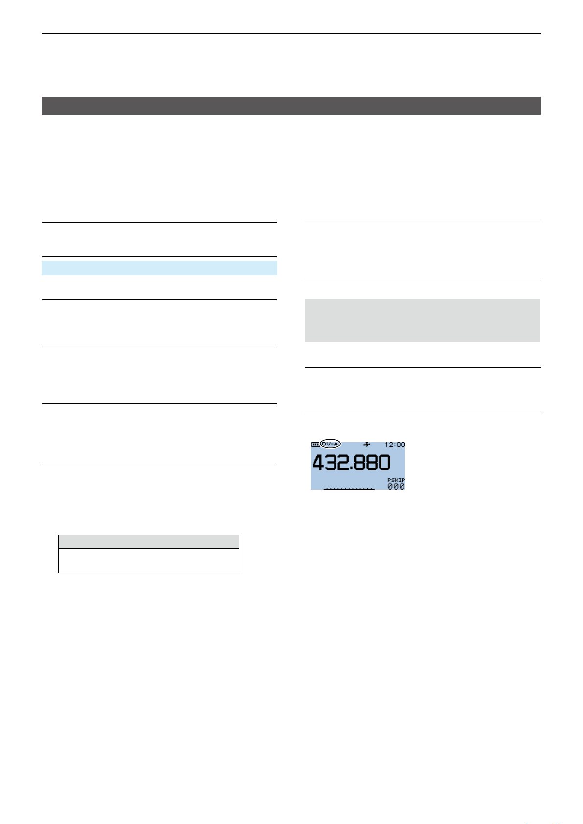
5
GPS OPERATION
Transmitting D-PRS data
D Setting D-PRS Position (Mobile)
Set each item to transmit as a D-PRS Position
(Mobile).
L You can receive Position (Base), Object, Item, or
Weather format data but cannot transmit them with
the ID-31A PLUS or ID-31E PLUS.
1. Setting the operating mode to DV mode
Push [FM/DV] to select the DV mode.
2. Setting the GPS TX Mode to D-PRS
MENU > GPS > GPS TX Mode > D-PRS (DV-A)
3. Checking the Unproto Address
You should use the default address, and editing is not
recommended.
4. Setting the Symbol
Select the Symbol that indicates your operating
situation�
L See p. 11-15 to directly enter the Symbol.
5. Setting the SSID
To assist in identifying your station’s type, add the
®
APRS
(Automatic Packet Reporting System) based
SSID after the D-PRS data call sign. (p. 5-13)
6. Entering a comment
Enter a comment of up to 43 characters, and transmit
it with the D-PRS position data.
1� Select “Comment.”
2� Push [QUICK].
3� Select “Edit.”
4� Enter a comment.
Selectable characters and symbols
A to Z, a to z, 0 to 9, ! " # $ % & ’ ( ) * +
, - . / : ; < = > ? @ [ \ ] ^ _ ` { | } ˜ (space)
L See page iii on how to enter characters.
L The symbol “
range. Note that the characters that exceed the
range is not transmitted.
¬
” shows the transmittable comment
5� After entering, push [ENT].
6� Push [ENT] again.
7. Setting the Time Stamp
Set the Time Stamp function to transmit the received
time data in UTC (Universal Time Coordinated) time.
(p. 5-14)
8. Setting the Altitude
Set the altitude data acquired from the GPS receiver.
NOTE: If you transmit with the altitude setting ON,
the character string is included in a comment on the
products that cannot display the altitude.
9. Setting the Data Extension
Set the Data Extension to “Course/Speed” to transmit
as a mobile station.
10. Exiting the MENU screen
Push [MENU].
• Returns to the standby screen, then “DV-A” is displayed.
5-12
Page 80
5
GPS OPERATION
Transmitting D-PRS data
D About each setting item
Unproto Address
Displays an unproto address of up to 56 alphanumeric
characters.
NOTE: You should use the default address, and
editing is not recommended.
Symbol
Select the symbol that indicates your operating
situation. The selected Symbol channel’s Symbol
(1 ~ 4) is transmitted with position data.
L See “Selectable Symbol list.” (p. 5-15)
TIP: To change the Symbol
1� Select a Symbol channel you want to edit.
L Do not push [ENT].
2� Push [QUICK].
3� Select “Edit Symbol.”
4� Select a Symbol.
• Sets the Symbol into the Symbol channel.
SSID
Select an SSID based on APRS
®
to add to your call
sign, to show your operating style to other stations.
The addition methods of the SSID differ, depending on
whether the call sign includes a space or not.
• ---: The space in call sign is converted to “-.”
L If no text is entered after the space, the space
will be deleted, and the space is not converted
to “-.”
Example: JA3YUA → JA3YUA
JA3YUA A → JA3YUA-A
• (-0): No SSID is added.
L If a call sign includes a space, any text or digit
after the space will be deleted.
Example: JA3YUA → JA3YUA
JA3YUA A → JA3YUA
• -1~-15: Adds an SSID of -1 to -15 to your call sign.
L Example: SSID is “-9.”
JA3YUA → JA3YUA-9
JA3YUA A → JA3YUA-9
• -A~-Z: Adds an SSID of -A to -Z to your call sign.
L Example: SSID is “-Z.”
JA3YUA → JA3YUA-Z
JA3YUA A → JA3YUA-Z
TIP: About the SSID
To assist in identifying a station’s type, designated
call sign SSIDs are used in D-PRS (or APRS®),
according to a common guideline.
The guideline may be changed when the
infrastructure environment, such as a product
or network, is changed. Please check the latest
guideline in the web site related to D-PRS and
APRS®, and correctly set.
http://aprs.org/aprs11/SSIDs.txt
Comment
Enter a comment to transmit it with the D-PRS
position data. You can enter up to 4 comments. The
number of characters you can enter differs, depending
on the Altitude and Data Extension settings�
( MENU > GPS > GPS TX Mode > D-PRS (DV-A) >
Altitude, Data Extension)
Data Extension
OFF OFF
OFF ON
Course/Speed
Course/Speed
Altitude
OFF
ON
Characters
entered
(Maximum)
43 (Default)
35
36
28
The symbol “ ” displays the transmittable comment
range. Note that the characters that exceed the range
are not transmitted.
Transmittable comment range display
(In case of up to 28 characters)
5-13
Page 81

5
GPS OPERATION
Transmitting D-PRS data
D About each setting item (Continued)
Time Stamp
Select the transmitting time stamp type.
The time stamp is transmitted with position data in the
D-PRS mode, and UTC (Universal Time Coordinated)
time is used.
L When your position is manually set, time stamp data is
not transmitted.
• OFF: Does not transmit the time information.
• DHM: Transmits the time stamp in the Day, Hour,
and Minute format.
• HMS: Transmits the time stamp in the Hour, Minute,
and Second format.
Altitude
Select whether or not to transmit altitude data with the
position data in the D-PRS mode.
L The number of characters you can enter in Comment
differs, depending on the Altitude and Data Extension
settings�
( MENU > GPS > GPS TX Mode > D-PRS (DV-A) >
Comment, Altitude, Data Extension)
• OFF: No altitude data is transmitted.
• ON: Transmits altitude data with position data.
Data Extension
Select whether or not to transmit course/speed data
with position data in the D-PRS mode.
L The number of characters you can enter in Comment
differs, depending on the Data Extension and Altitude
settings�
• OFF: Does not transmit any information.
• Course/Speed: Transmits course and speed data
with the position data.
L The Course and Speed data is not
transmitted when your position is
manually set.
L When transmitting with this setting,
your station is regarded as a mobile
station�
5-14
Page 82
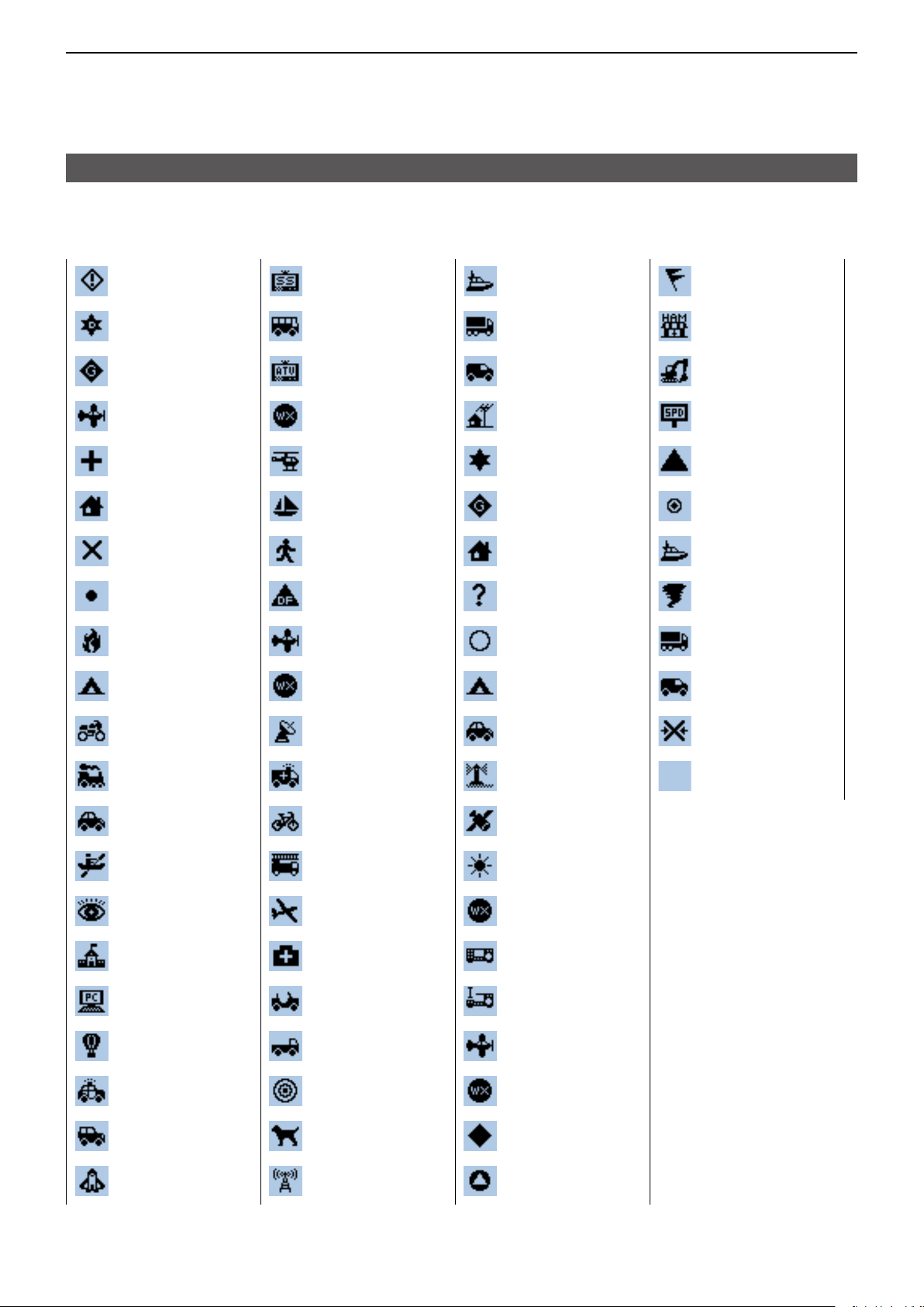
5
GPS OPERATION
Transmitting D-PRS data
D About each setting item (Continued)
Selectable Symbol list
Sheriff
Digipeater
Gateway
Small Aircraft
Red Cross
House QTH
(VHF)
X
Red Dot
Fire
Campground
SSTV
Bus
ATV
WX Service
Helicopter
Yacht
Person
DF Station
Large Aircraft
WX Station
Ship (powerboat)
Truck
(18-wheeler)
Van
Yagi @ QTH
Overlayed
Digipeater
Overlayed
Gateway
House (HF)
Big Question
Mark
Circle
Park/Picnic Area
Gale Flags
Ham Store
Work Zone
Speed post
(Value Signpost)
Triangle
Small Circle
Overlayed Ship
Tornado
Overlayed Truck
Overlayed Van
Motorcycle
Railroad Engine
Car
Canoe
Eyeball
School
PC User
Balloon
Police
Recreational
Vehicle
Dish Antenna
Ambulance
Bicycle
Fire Truck
Glider
Hospital
Jeep
Truck
Node
Rover
Overlayed Car
Lighthouse
Satellite
Sunny
Overlayed WX
Service
Radio
Icom Radio
Aircraft
Overlayed WX
Station
Overlayed
Diamond
Wreck
Other
Shuttle
Repeater
RACES
5-15
Page 83
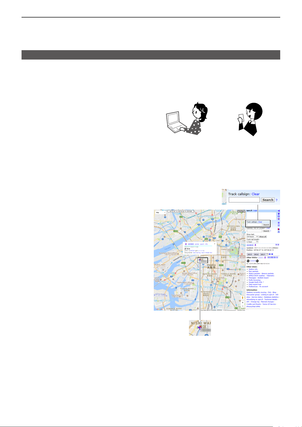
5
GPS OPERATION
Transmitting D-PRS data
D Displaying your position using a mapping software
If you transmit to an I-GATE station, and then enter
the call sign information on the Internet map website,
the selected symbol is displayed.
Example: Check your position on the APRS. site.
You can check on the Internet!
PC Smartphone
1� Display a free APRS
Internet�
L Example: http://aprs./
2� Enter your call sign in the “Track callsign” field.
3� Click <Search>.
• The icon (D-PRS symbol) is displayed on the map site.
®
related map site on the
Enter your call sign, and
then click <Search>.
5-16
← Your symbol and
your call sign
Page 84
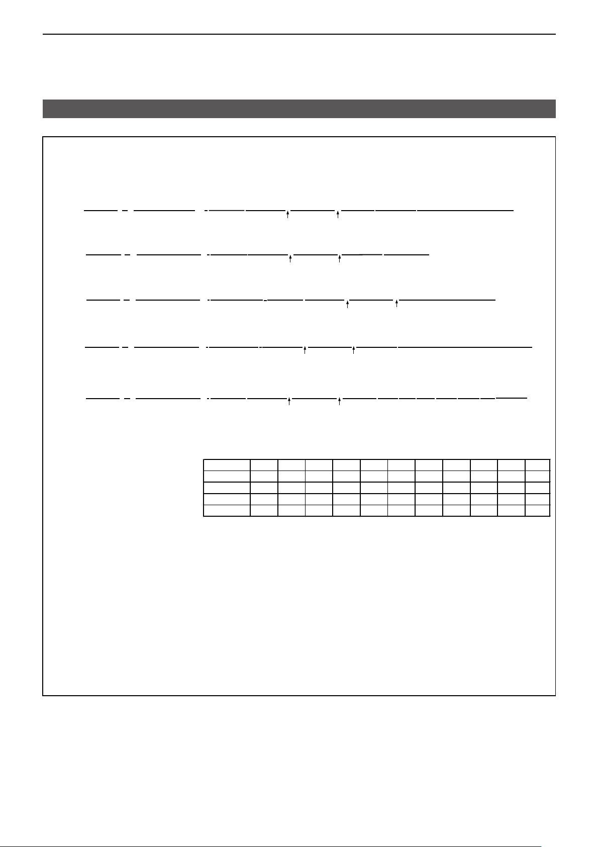
5
GPS OPERATION
Transmitting D-PRS data
TIP:
D-PRS data content
D-PRS data content are shown below.
DPosition (Mobile)
JA3YUA-A>API31,DSTAR*:/002338h3437.38N/13534.29E>090/002/A=000012ID-31PLUS OP.SATOH
(e.g.)
DPosition (Base)
(e.g.)
DObject
(e.g.)
DItem
(e.g.)
DWeather
q
w
JA3YUA-A>API410,DSTAR*:/002338h3437.38N/13534.29E-PHG5132OP.SATOH
q
w
JA3YUA-A>API410,DSTAR*:;HAM FESTA*012345z3437.38N\13534.29Eh2017.10.31 am10-pm4
q
w
JA3YUA-A>API410,DSTAR*:)REPEATER!3454.00N/13536.00ErPHG5132439.39MHz DV RPT JP3YHH A
q
w
e
e
e
e
r
u
r
u
r
r
t
i
i
t
u
y
i
y
!0
o
!0
o
i
o
!1
o
!2
o
o
!0
o
!3 !4
!4
!0
o
!2
!4
!4
JA3YUA-A>API410,DSTAR*:/012345z3454.00N/13536.00E_220/004g005t077r000p000P000h50b09900
(e.g.)
qCall sign
wSSID
eUnproto Address
rD-PRS Data type
/ Position with time stamp
! Position without time stamp
; Object
) Item
q
w
e
r
u
i
!0
!5
oo
!7
!6
!8
@0
!9
!2Data Extension(PHG codes)
PHG codes definitions
First: Power
Second: Height
Third: Gain
Fourth: Directivity
0
0
10
0
omni
1
1
20
1
45°NE
2
4
40
2
90°E
3
9
80
3
135°SE
4
16
160
4
180°S
320
225°SW
6
5
25
640
5
270°W
7
36
49
1280
6
7
315°NW
tObject Name/Item Name
yData Type
* Live Object
! Live Item
_ Killed Object/Killed Item
uTime Stamp (UTC)
h Hour Minute Second
z Day Hour Minute
iLatitude
oSymbol
!0Longitude
!1Data Extension (Course/Speed)
Course:0 ~ 360°
!3Altitude
−99999 ~ 999999 feet
!4Comment
!5Wind direction/Wind speed
Wind direction:0 ~ 360°
Wind speed: 0 ~ 999 mph
!6Gust speed
0 ~ 999 mph
!7Temperature
−99 ~ 999ƒ
!8Rainfall
0.00 ~ 9.99 inch
!9Rainfall (24 Hours)
0.00 ~ 9.99 inch
@0Rainfall (Midnight)
0.00 ~ 9.99 inch
@1Humidity
1 ~ 99%, 00=100%
@2Barometric pressure
0.0 ~ 9999.9 hPa
Speed:0 ~ 999 knots
@1
8
64
2560
8
360°N
@2
9
81
5120
9
−
(W)
(feet)
(dB)
−
5-17
Page 85
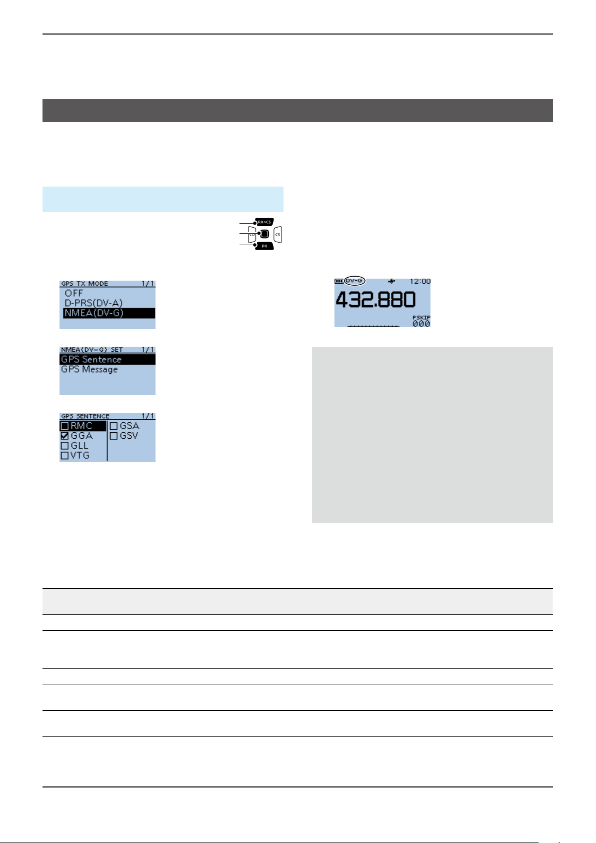
5
GPS OPERATION
Transmitting NMEA data
Set a GPS sentence to transmit GPS data in the DV
mode.
D Setting the GPS data sentence
MENU > GPS > GPS TX Mode > NMEA (DV-G)>
GPS Sentence
1� Push [MENU].
2� Select “GPS.”
3� Select “GPS TX Mode.”
4� Select “NMEA (DV-G)” and then
select “GPS Sentence.”
▼
[Up]
[ENT]
[Down]
6� Repeat step 5 to set the GPS sentence.
L Up to 4 GPS sentences can be set at a time.
7� Push [MENU].
• Returns to the standby screen, then “DV-G” is
displayed.
5� Select the GPS sentence.
• Displays “✓” when the sentence is set to ON.
L The selectable GPS sentences are RMC, GGA, GLL,
VTG, GSA, and GSV. The GGA sentence is set to
ON as the default GPS sentence.
L Pushing [QUICK] and selecting “Default” returns to
the default setting.
Contents of GPS sentence
Sentence
RMC
GGA
GLL
Lon/Lat Alt UTC
✔ ✔ ✔ ✔ ✔ ✔
✔ ✔ ✔ ✔
✔ ✔ ✔
Date
(UTC)
VTG
GSA
GSV
Status
✔ ✔
2D
/3D
NOTE:
• Set GSV Sentence to “OFF” when sending
the GPS message to a conventional digital
transceivers. (p. 5-4)
• If GPS Select is set to “Manual,” the transceiver
automatically sets the NMEA sentence, and
transmits it along with the manually entered
position data in Manual Position. (p. 11-9)
(GPS > GPS Set > GPS Select)
(GPS > GPS Set > Manual Position)
• Note that if GPS Auto TX is set to any other
option than “OFF,” data is automatically
transmitted according to the set time. (p. 11-18)
(GPS > GPS Auto TX)
COG
(True)
SOG
(knot)
Others
Magnetic variation, Mode Indicator
Number of satellites in use, HDOP,
Geoidal separation, Age of Differential
GPS data
Mode Indicator
✔ ✔
COG (Magnetic north), SOG (km/h),
Mode Indicator
ID numbers of satellites used in
solution, PDOP, HDOP, VDOP
Total number of sentences, Sentence
number, Total number of satellites
in view, Satellite information (ID,
Elevation, Azimuth, S/N)
5-18
Page 86
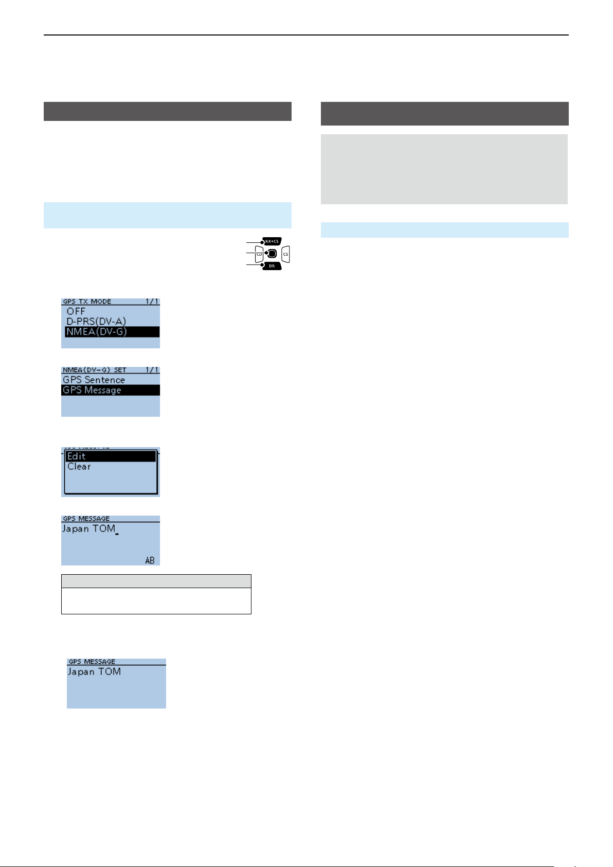
5
GPS OPERATION
Transmitting NMEA data
D Entering a GPS message
Enter a GPS message to be transmitted with the
position data.
Example: Entering “Japan TOM”
MENU > GPS > GPS TX Mode > NMEA (DV-G)>
GPS Message
1� Push [MENU].
2� Select “GPS.”
3� Select “GPS TX Mode.”
4� Select “NMEA (DV-G)” and then
select “GPS Message.”
▼
[Up]
[ENT]
[Down]
GPS Automatic Transmission
NOTE:
• Use the GPS Automatic Transmission function in
only the Simplex mode.
• Using the function through a Repeater may
interfere with other communications.
MENU > GPS > GPS Auto TX
If you set the GPS Automatic Transmission function,
GPS data is automatically transmitted according to the
set time.
L This function is not activated if your call sign (MY)
is not entered in the transceiver.
L If GPS Select is set to “OFF” or“Manual,” this
function is not activated.
5� Push [QUICK].
6� Select “Edit.”
7� Enter a GPS message of up to 20 characters.
(Example: Japan TOM)
Selectable characters and symbols
A to Z, a to z, 0 to 9, ! " # $ % & ’ ( ) * +
, - . / : ; < = > ? @ [ \ ] ^ _ ` { | } ˜ (space)
L See page iii on how to enter characters.
8� After entering, push [ENT].
• Displays the entered message.
L To exit the MENU screen, push [MENU].
5-19
Page 87
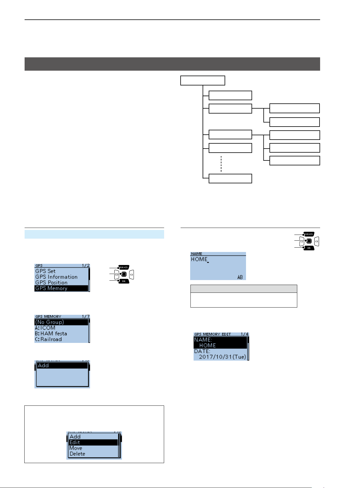
5
GPS OPERATION
GPS Memory
You can add GPS data to GPS Memory.
You can add your own position, other station’s
position, or any positions that are manually entered.
You can save the GPS Memory up to 200 channels,
and conveniently saved in up to 27 groups, from A ~
Z and “(No Group).” The A to Z groups can also be
named.
D Adding a GPS Memory
Example: Add "HOME" into (No Group)
1. Adding a GPS Memory and entering the edit
mode
MENU > GPS > GPS Memory
1� Push [MENU].
2� Select “GPS.”
3� Select “GPS Memory.”
[Up]
[ENT]
[Down]
GPS Memory
(No Group)
A: ICOM
B: HAM festa
C: Railroad
Z:
Group names are just
examples.
Icom Osaka HC
Icom America
Tokyo Big Sight
Dayton Hamvention
Friedrichshafen
2. Entering a GPS Memory name
1� Select “NAME.”
2� Enter a GPS Memory name of up
to 16 characters.
(Example: HOME)
[Up]
[ENT]
[Down]
• The previously added GPS Memories are displayed on
the GPS MEMORY screen.
4� Select “(No Group).”
5� Push [QUICK].
6� Select “Add.”
• The GPS MEMORY EDIT screen is displayed.
TIP: To edit the previously saved GPS Memory,
select “Edit” in step 6. You can enter the content in
the same way as described above.
Selectable characters and symbols
A to Z, a to z, 0 to 9, ! " # $ % & ’ ( ) * +
, - . / : ; < = > ? @ [ \ ] ^ _ ` { | } ˜ (space)
L See page iii on how to enter characters.
3� After entering, push [ENT].
• Returns to the GPS MEMORY EDIT screen.
►Continued on the next page.
5-20
Page 88
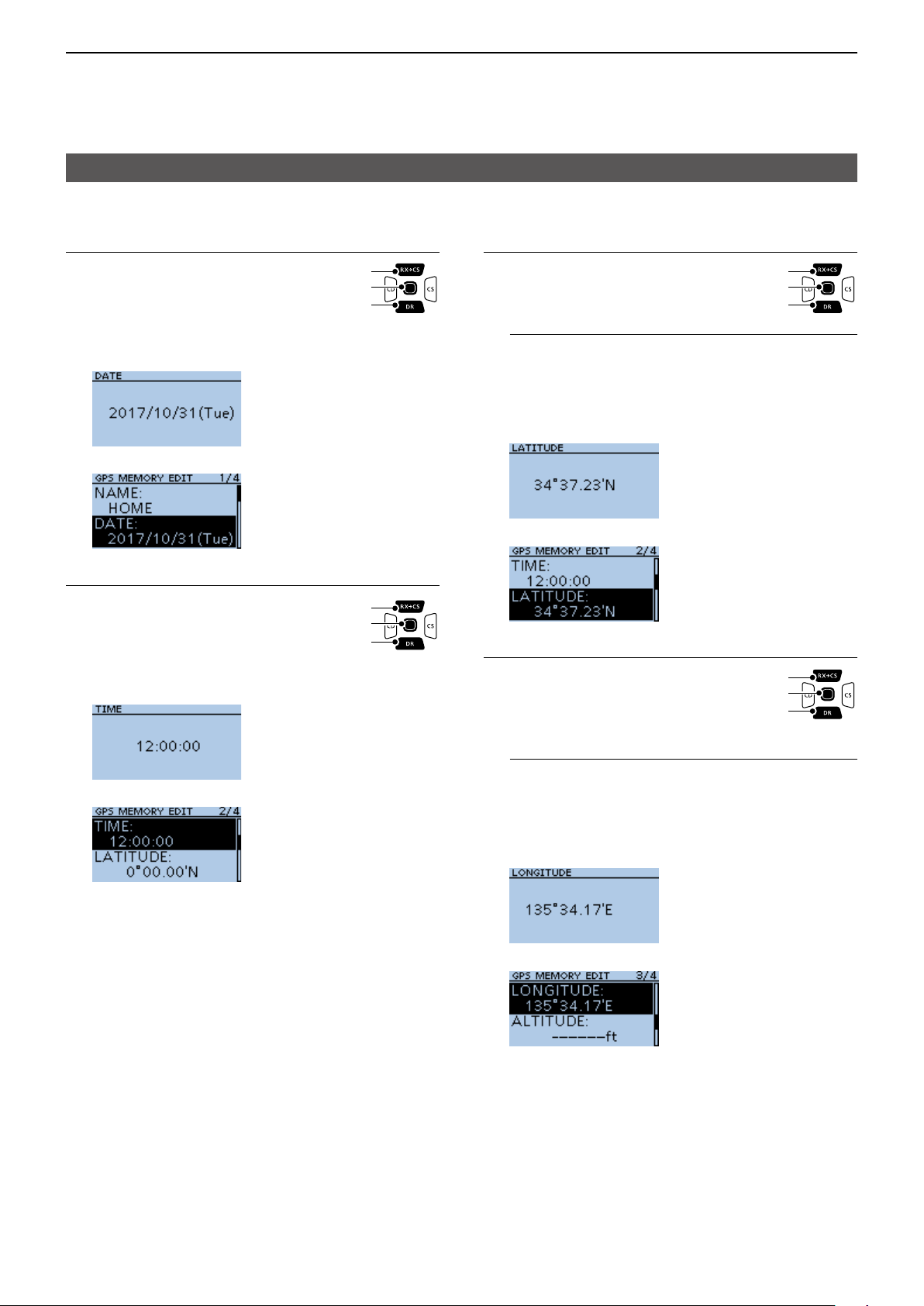
5
GPS OPERATION
GPS Memory
D Add a GPS Memory (Continued)
3. Entering the GPS Memory date
1� Select “DATE.”
2� Push [CD] or [CS] to move the
cursor to select a digit to enter.
[Up]
[ENT]
[Down]
3� Rotate [DIAL] to enter the date.
L Set to between 2000/01/02 and 2099/12/30.
4� Repeat steps 2 and 3 to enter the date.
5� After entering, push [ENT].
4. Entering the GPS Memory time
1� Select “TIME.”
2� Push [CD] or [CS] to move the
cursor to select a digit to enter.
[Up]
[ENT]
[Down]
3� Rotate [DIAL] to enter the time.
L Set to between 00:00:00 and 23:59:59.
4� Repeat steps 2 and 3 to enter the time.
5� After entering, push [ENT].
5. Entering the GPS Memory latitude
1� Select “LATITUDE.”
2� Push [CD] or [CS] to move the
cursor to select a digit to enter.
[Up]
[ENT]
[Down]
3� Rotate [DIAL] to enter the latitude.
InformationL
• Set to between 0°00.00' to 90°00.00'.
• You can change the unit to “ddd°mm'ss".” (p. 11-41)
• To enter a north latitude, select “N,” and to enter a
south latitude, select “S.”
4� Repeat steps 2 and 3 to enter the latitude.
5� After entering, push [ENT].
6. Entering the GPS Memory longitude
1� Select “LONGITUDE.”
2� Push [CD] or [CS] to move the
cursor to select a digit to enter.
[Up]
[ENT]
[Down]
3� Rotate [DIAL] to enter the
longitude.
InformationL
• Range: Set to between 0°00.00' to 180°00.00'.
• You can change the unit to “ddd°mm'ss".” (p. 11-41)
• To enter an east longitude, select “E,” and to enter a
west longitude, select “W.”
4� Repeat steps 2 and 3 to enter the longitude.
5� After entering, push [ENT].
5-21
►Continued on the next page.
Page 89

5
GPS OPERATION
GPS Memory
D Add a GPS Memory (Continued)
7. Entering the GPS Memory altitude
1� Select “ALTITUDE.”
2� Rotate [DIAL] to select plus or
minus.
[Up]
[ENT]
[Down]
3� Push [CD] or [CS] to move the
cursor to select a digit to enter.
4� Rotate [DIAL] to enter the altitude.
L Set to between –32808 and +32808 feet.
5� Repeat steps 3 and 4 to enter the altitude.
6� After entering, push [ENT].
8. Selecting a GPS Memory group
1� Select “GROUP.”
[Up]
[ENT]
[Down]
9. Writing the GPS Memory
1� Select “<<Add Write>>.”
[Up]
[ENT]
[Down]
• The conrmation dialog is displayed.
L If you edit a previously added GPS Memory, select
“<<Overwrite>>.”
2� Select <YES>.
• The data is added to the GPS memory, and then the
selected GPS Memory group screen is displayed.
L To exit the MENU screen, push [MENU].
2� Select the group between
(No Group) and A ~ Z.
L You can save up to 200 Memories in each group.
TIP:
To view the entered content:
Select the GPS Memory channel. Rotate [DIAL] to
check the whole content.
To cancel the entered data:
While entering or editing the GPS Memory, push
[CLR] to display the conrmation dialog, as shown
below.
Select <YES> to cancel entering and the display
returns to the GPS Memory group screen.
5-22
Page 90

5
GPS OPERATION
GPS Memory
D Entering the GPS Memory group name
You can enter a name for each GPS Memory group.
MENU > GPS > GPS Memory
1� Push [MENU].
2� Rotate [DIAL] to select “GPS.”
3� Select “GPS Memory.”
• Displays the GPS MEMORY screen.
4� Select the group that the name to be entered,
then push [QUICK].
5� Select “Edit Name.”
6� Enter a group name of up to 16 characters.
( Example: HOME AREA)
D Deleting GPS Memory
You can delete the GPS Memories.
There are 2 ways to delete the Memories:
• Deletes all GPS Memory in a group.
• Deletes a specic GPS Memory.
NOTE: Deleted GPS Memories cannot be restored.
MENU > GPS > GPS Memory
Example: Deleting all in the Group E.
1� Push [MENU].
2� Select “GPS.”
3� Select “GPS Memory.”
• Displays the GPS MEMORY screen.
4� Select the group where the GPS Memory to
delete is saved, then push [QUICK].
5� Select “Delete All In Group.”
Selectable characters and symbols
A to Z, a to z, 0 to 9, ! " # $ % & ’ ( ) * +
, - . / : ; < = > ? @ [ \ ] ^ _ ` { | } ˜ (space)
L See page iii on how to enter characters.
7� After entering, push [ENT].
L To exit the MENU screen, push [MENU].
• The conrmation dialog is displayed.
6� Select <YES>.
• All GPS Memory in the selected group are deleted,
then returns to the GPS MEMORY screen.
L When selecting a blank group, “Blank” is displayed.
L To exit the MENU screen, push [MENU].
TIP: Deleting a specic GPS Memory
You can delete a specic GPS Memory.
1� Select the GPS Memory to delete, then push
[QUICK].
2� Select “Delete.”
3� Select <YES>.
5-23
• The conrmation dialog is displayed.
• The selected GPS Memory is deleted.
Page 91
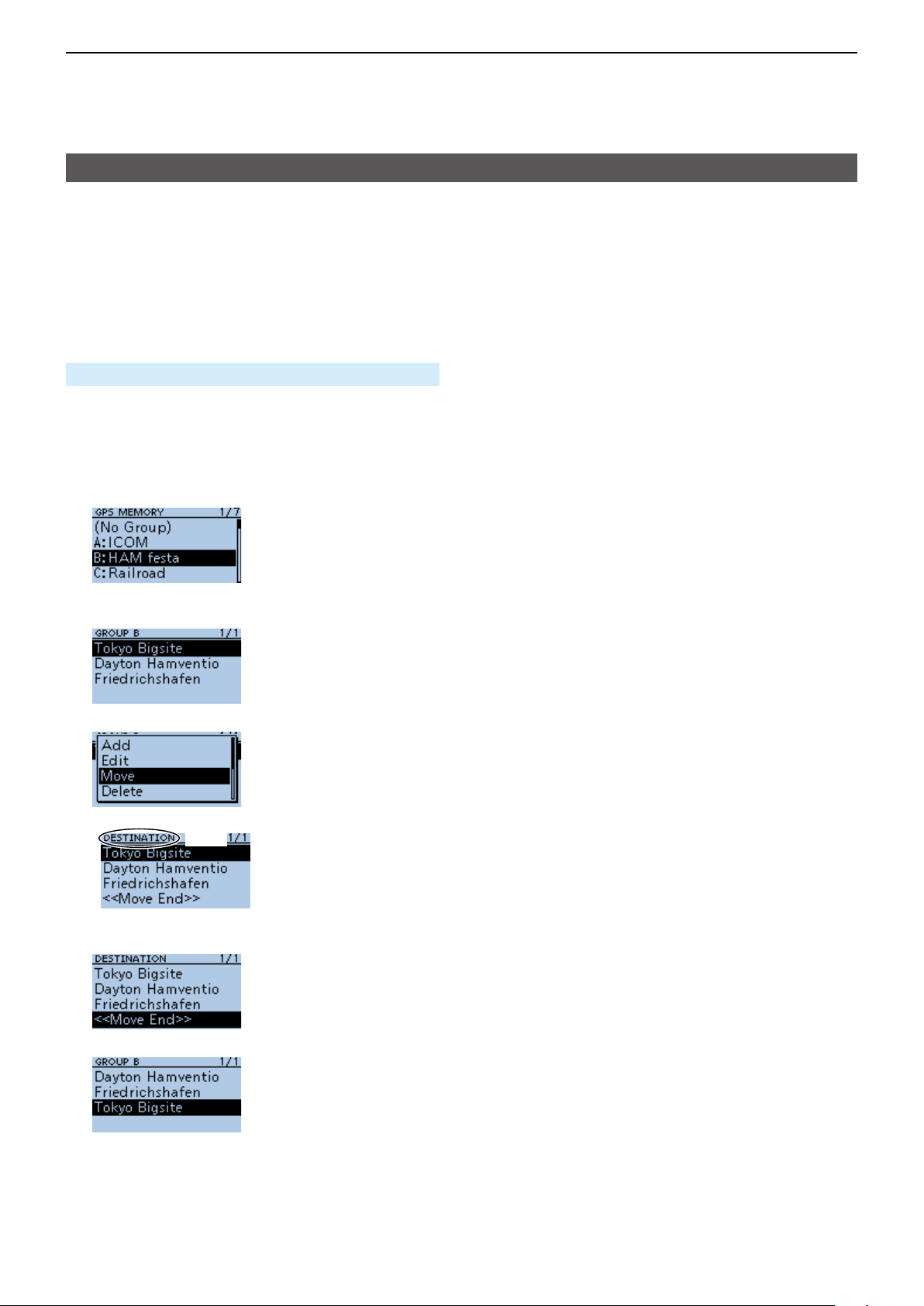
5
GPS OPERATION
GPS Memory
D Rearranging the display order of the GPS data
You can move the entered GPS Memories to
rearrange their display order in the selected GPS
Memory group.
In order to move the GPS Memory out of their
assigned Memory group, edit and move, and then
save.
MENU > GPS > GPS Memory
1� Push [MENU].
2� Select “GPS.”
3� Select “GPS Memory.”
• Displays the GPS MEMORY screen.
4� Select the group where the GPS Memory you
want to move is saved.
5� Select the GPS Memory to move, then push
[QUICK].
6� Select “Move.”
• “DESTINATION” blinks at the top left of the screen.
Blinks
7� Select the position to insert the Memory you want
to move.
▼
• The selected Memory is inserted above the destination
Memory name.
L If you select “<<Move End>>,” the Memory is moved
to the bottom of the group.
L To exit the MENU screen, push [MENU] several
times.
5-24
Page 92

5
GPS OPERATION
GPS Alarm
The transceiver can sound a GPS Alarm when a target station or position comes into the alarm area.
This function can be set to a caller station, all GPS Memories, a selected GPS Memory group, or a selected GPS
Memory.
Alarm Area (Group) (Setting plural stations)
When “All Memories” or a GPS Memory group is selected:
Point A
Your location
Point B
0.25’ 0.25’
0.25’ 0.25’
Point C
Sounds 3 beeps.
Alarm Area (RX/Memory) (Setting specic station)
When a specic GPS Memory is selected:
Extended range
Approximately 1 km, 1094 Y
Limited range
Approximately 500 m, 547 Y
N
N
Your location
Target station
Sounds 3 beeps.Sounds a beep.
5-25
Page 93

5
GPS OPERATION
GPS Alarm
D Setting the GPS Alarm function to All
Memories (all GPS Memories)
MENU > GPS > GPS Alarm
1� Push [MENU].
2� Select “GPS.”
3� Select “GPS Alarm.”
4� Select “Alarm Select.”
5� Select “Group.”
6� Select “All Memories.”
▼
[Up]
[ENT]
[Down]
InformationL
• When either one of the stations in the group enters
the set range, the alarm sounds 3 times.
• When the transceiver sounds a GPS Alarm, “GPS
ALARM” pops up on the screen, and “S” blinks.
See the illustration below.
• To cancel the GPS Alarm function, select “OFF” in
step 5 to the left.
Blinks
“GPS ALARM” pops up on the screen and
the alarm sounds 3 times.
TIP: When selecting “All Memories,” “No Group,” or
a GPS Memory group (A ~ Z) in step 6 to the left,
you also have to set Alarm Area (Group) to use
the GPS Alarm function. (p. 11-13)
( MENU > GPS > GPS Alarm > Alarm Area
(Group))
• Returns to the GPS ALARM screen.
L If you want to set the alarm to a specic GPS
Memory group, select “(No Group)” or “A” to “Z.”
L To exit the MENU screen, push [MENU].
5-26
Page 94

5
GPS OPERATION
GPS Alarm
D Setting the GPS Alarm function to RX
(a caller station)
MENU > GPS > GPS Alarm
1� Push [MENU].
2� Select “GPS.”
3� Select “GPS Alarm.”
[Up]
[ENT]
[Down]
4� Select “Alarm Select.”
InformationL
• When a station with its GPS Alarm set enters within
an approximate 1 kilometer (1094 yard) range,
the alarm sounds once. When it enters within an
approximate 500 meter (547 yard) range, the alarm
sounds 3 times.
• When the transceiver sounds a GPS Alarm, “GPS
ALARM” pops up on the screen, and “S” blinks.
See the illustration below.
• To cancel the GPS Alarm function, select “OFF” in
step 5 to the left.
Blinks
5� Select “RX.”
▼
• Returns to the GPS ALARM screen.
L If you want to set the alarm to a specic GPS
Memory, select “Memory” and then select a GPS
Memory in a GPS Memory group.
L To exit the MENU screen, push [MENU].
“GPS ALARM” pops up on the screen and
the alarm sounds, depending on the set range.
NOTE: Even if “RX” is selected in step 5, when
the received signal has no position data, the GPS
Alarm does not sound.
TIP: When selecting “RX” or a specific GPS
Memory in step 6 to the left, you also have to set
Alarm Area (RX/Memory) to use the GPS Alarm
function. (p. 11-14)
( MENU > GPS > GPS Alarm > Alarm Area (RX/
Memory))
5-27
Page 95

5
GPS OPERATION
GPS Logger function
The GPS Logger function enables you to save
position data from a GPS receiver into a microSD card
as a log.
The GPS Logger saves Latitude, Longitude, Altitude,
Positioning state, Course, Speed, Date, and Time.
If you use this GPS Logger while driving, you can
check your driving history on a mapping software.
D GPS Logger operating outline
To use GPS Logger function, perform following
operations�
1� Insert a microSD card*.
*User supplied.
2� Check whether or not the GPS receiver is
receiving your position data. (p. 5-3)
3� Turn ON the GPS Logger function.
Completed!
You can start using the GPS Logger function.
NOTE:
• The GPS Logger function requires a microSD card
(User supplied).
• Once the GPS Logger function is turned ON, the
transceiver continuously saves position data from
the GPS receiver, even if the transceiver is turned
OFF, then ON again. To cancel this function, turn
OFF the function. While this function is ON, and
when the transceiver is turned OFF, the log le will
be closed. Then the transceiver is turned ON and
Positioning is carried out by the GPS receiver, a
new log le will be created.
• When the microSD card is full, this function is
automatically paused.
TIP: Using the <<GPS Logger Only>> mode
The transceiver has the exclusive GPS Logger
mode where only the GPS Logger functions.
This mode is useful when you are traveling and do
not want to use the transceiver for communication,
but you do want to use just the GPS Logger.
See page 5-32 for details.
D Conrming the GPS Logger function
Conrm the GPS Logger function is turned ON.
When the GPS Logger function is ON, the transceiver
saves the position data from the GPS receiver into a
microSD card in a set time interval.
L The saved GPS sentences are GGA, RMC, GSA,
and VTG.
NOTE: When using an external GPS receiver, the
saved GPS sentences differ depending on GPS the
receiver you use.
MENU > GPS > GPS Logger > GPS Logger
1� Push [MENU].
2� Select “GPS.”
3� Select “GPS Logger.”
[Up]
[ENT]
[Down]
4� Select “GPS Logger” on the GPS
LOGGER screen.
5� Select “ON.”
L The default setting is “ON.”
L To exit the MENU screen, push [MENU].
D Setting the GPS record interval
For example, when you are walking and if the time
interval is set to “1 sec,” a lot of position data is saved
at near place. Select the GPS Logger function record
interval to suit your travel speed.
MENU > GPS > GPS Logger > Record Interval
1� Push [MENU].
2� Select “GPS.”
3� Select “GPS Logger.”
4� Select “Record Interval.”
[Up]
[ENT]
[Down]
5� Select a record interval.
L Set to between 1, 5, 10, 30, and 60 seconds.
L To exit the MENU screen, push [MENU].
5-28
Page 96
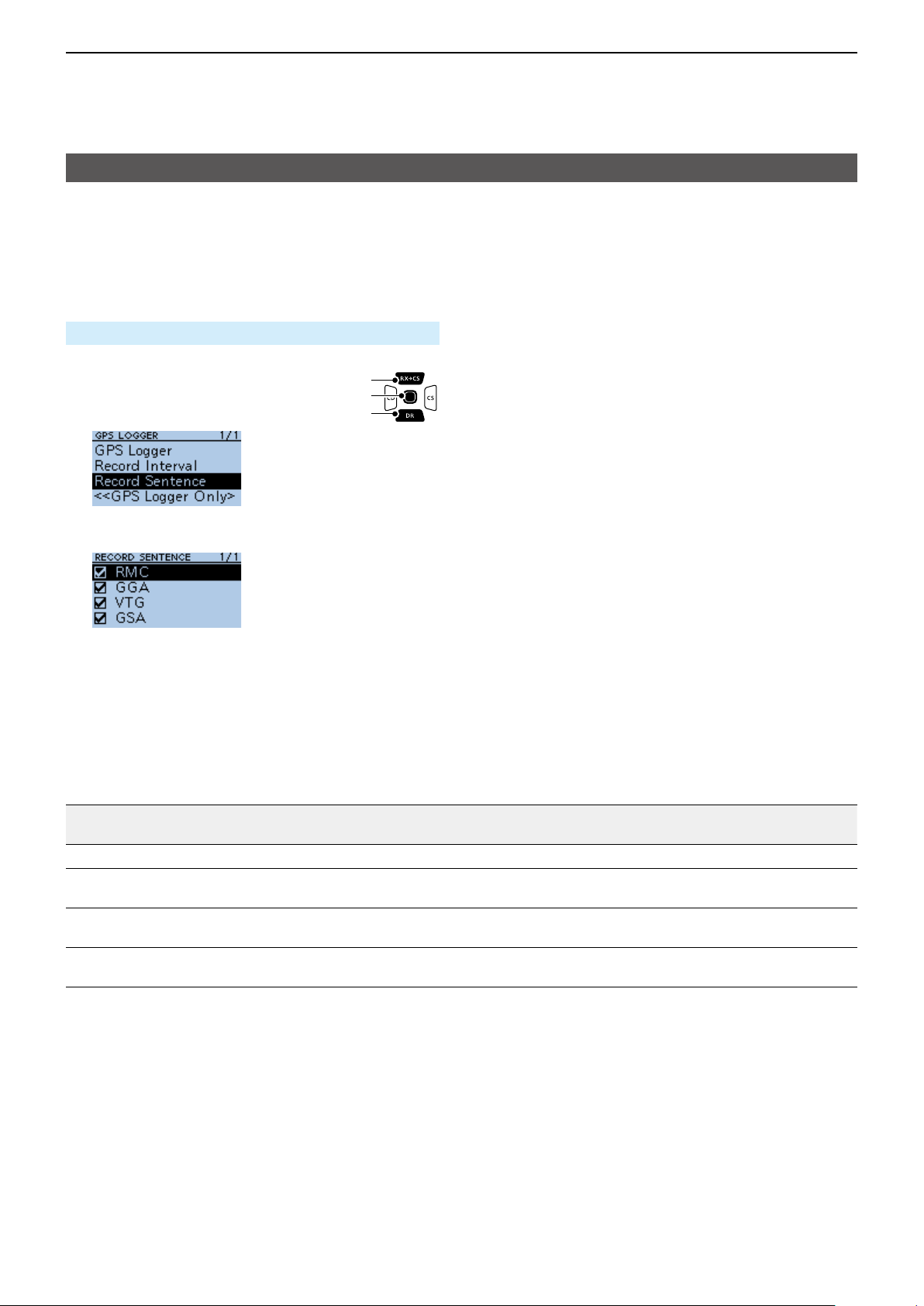
5
GPS OPERATION
GPS Logger function
D Setting the GPS record sentence
Select the GPS sentence for the GPS Logger function.
Select only required sentences to reduce the data
volume.
See the contents table shown below before selecting.
MENU > GPS > GPS Logger > Record Sentence
1� Push [MENU].
2� Select “GPS.”
3� Select “GPS Logger.”
4� Select “Record Sentence.”
5� Push [ENT] to remove the checkmark from the
unrequired sentence.
[Up]
[ENT]
[Down]
• “✓” disappears when the sentence is set to OFF.
L The selectable GPS sentences are RMC, GGA,
VTG, and GSA. All sentences are set to ON as the
default.
L To exit the MENU screen, push [MENU].
Contents of GPS sentence
Sentence
RMC
GGA
Lon
Alt UTC
/Lat
✔ ✔ ✔ ✔ ✔ ✔
✔ ✔ ✔ ✔
Date
(UTC)
Status
VTG
GSA
✔ ✔
2D
/3D
COG
(True)
✔ ✔
SOG
(knot)
Others
Mode Indicator
Number of satellites in use, HDOP, Geoidal
separation, Age of Differential GPS data
COG (Magnetic north), SOG (km/h), Mode
Indicator
ID numbers of satellites used in solution, PDOP,
HDOP, VDOP
5-29
Page 97
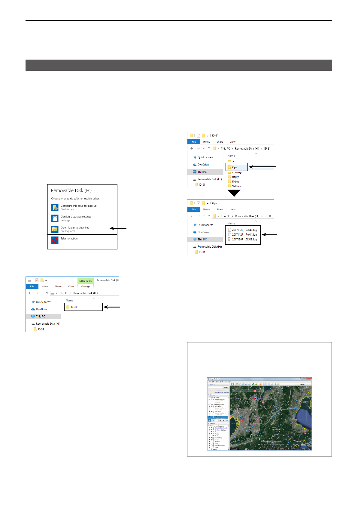
5
GPS OPERATION
GPS Logger function
D Viewing the log data on a PC Map
If you want to display your log data, copy the log le to
your PC.
L Windows 10 is used for these instructions.
1� Turn OFF the transceiver, then remove the
microSD card from the transceiver.
L To remove the card while the transceiver is ON,
unmount it rst. (See BASIC MANUAL Section 6)
2� Insert the card into the microSD card drive or a
memory card reader* on your PC.
*User supplied.
3� Click the “Open folder to view files” option to
access the card.
Click
• Displays the ‘ID-31’ folder.
4� Double-click the “ID-31” folder.
Double-click
5� Double-click the “Gps” folder.
Double-click
The log les
are saved here
• The log les are displayed.
L The les are named with the time the log was
started, in the following format:
yyyymmdd_hhmmss.log
yyyy = year, mm = month, dd = day, hh = hour,
mm = minute, ss = second
6� Import the log file to a mapping software.
• You can see your route on the software map.
L The le may not be compatible with all mapping
software.
• Displays 8 folders.
TIP: You can display your route on Google Earth
(free map software). Select “Open” in the <File>
menu of Google Earth to open the log le.
• Your route is displayed on the map, as shown below.
5-30
Page 98

5
*Blank shows when not positioned.
GPS OPERATION
GPS Logger function
TIP: About the recorded NMEA sentence for GPS logging
Regarding the GPS logging data of the ID-31A/E PLUS, each sentence corresponds to the NMEA standard
and is recorded in the following format.
D GGA sentence
(e.g.) $GPGGA,161229.487,3723.2475,N,12158.3416,W,1,07,1.0,9.0,M,25.5,M,3,0000*18<CR><LF>
q w e r y iu o
q GGA protocol header ($GPGGA)
w UTC of position (16:12:29.487)
e Latitude (North 37º 23.2475′) N=North, S=South
r Longitude (West 121º 58.3416′) E=East, W=West
t GPS quality indicator (1)
0=Fix not available or invalid, 1=SPS mode
2=DGPS (SPS), 6=Estimated (Dead Reckoning) mode
y Number of satellites in use (7), 00–12
D RMC sentence
$GPRMC,161229.487,A,3723.2475,N,12158.3416,W,0.13,309.62,311017, , ,D*10<CR><LF>
(e.g.)
q w r t y iu !0 !1
q RMC protocol header ($GPRMC)
w UTC of position (16:12:29.487)
e Status (A) A=Data valid
V=Data invalid/not positioned
r Latitude (North 37º 23.2475
t Longitude (West 121º 58.3416′) E=East, W=West
y Speed over ground (0.13 knots)
u Course Over Ground (309.62º; degrees True)
0.00º–359.99º
e
′) N=North, S=South
t
u Horizontal Dilution of Precision (1.0) 0.0–50.0
i Altitude re: mean-sea-level (geoid), meters
(9.0 meters)
o Geoidal separation, meters (25.5 meters)
!0 Age of Differential GPS data (3 seconds)
!1 Check Sum (*18) Error detection data
started with “*” (hex code)
!2 End code
*Blank shows when not positioned.
i UTC date of position
o Mode Indicator (D)
A=Autonomous mode, D=DGPS,
E=Estimated (dead reckoning) mode,
N=Data not valid, R=Almanac data
!0 Check Sum (*10) Error detection data
started with “*” (hex code)
!1 End code
*Blank shows when not positioned.
!0
!1 !2
o
(’17 Oct 31st) ddmmyy
D GSA sentence
$GPGSA,A,3,07,02,26,27,09,04, , , , , ,15,1.8,1.0,1.5*33<CR><LF>
(e.g.)
q r t y u i o
q GSA protocol header ($GPGSA)
w Mode indicator 1 (A)
M=Manual, forced to operate in 2D or 3D mode
A=Automatic, allowed to automatically switch 2D/3D
e Mode indicator 2 (3)
1=Fix not available,
2=2D (using satellites; less than 3),
3=3D (using satellites; more than 4)
r ID numbers of satellites used in solution (
01–32 *Shows up to 12 ID’s
e
w
07, 02, 26, 27, 09, 04…15)
D VTG sentence
$GPVTG,309.62,T, ,M,0.13,N,0.2,K,A*03<CR><LF>
(e.g.)
q w
q VTG protocol header ($GPVTG)
w Course Over Ground (309.62º; degrees True)
0.00º–359.99º
e Course over ground degrees; Magnetic north
r Speed over ground, knots (0.13 knots)
t Speed over ground, kilometer per hour (0.2 km/hr)
r t
u i
ye
t Position Dilution of Precision (1.8) 0.0–50.0
y Horizontal Dilution of Precision (1.0) 0.0–50.0
u Vertical Dilution of Position (1.5) 0.0–50.0
i Check Sum (*33) Error detection data
started with “*” (hex code)
o End code
*Blank shows when not positioned.
y Mode Indicator (A)
A=Autonomous mode, D=DGPS,
E=Estimated (dead reckoning) mode,
N=Data not valid, R=Almanac data
u Check Sum (*03) Error detection data
started with “*” (hex code)
i End code
5-31
Page 99
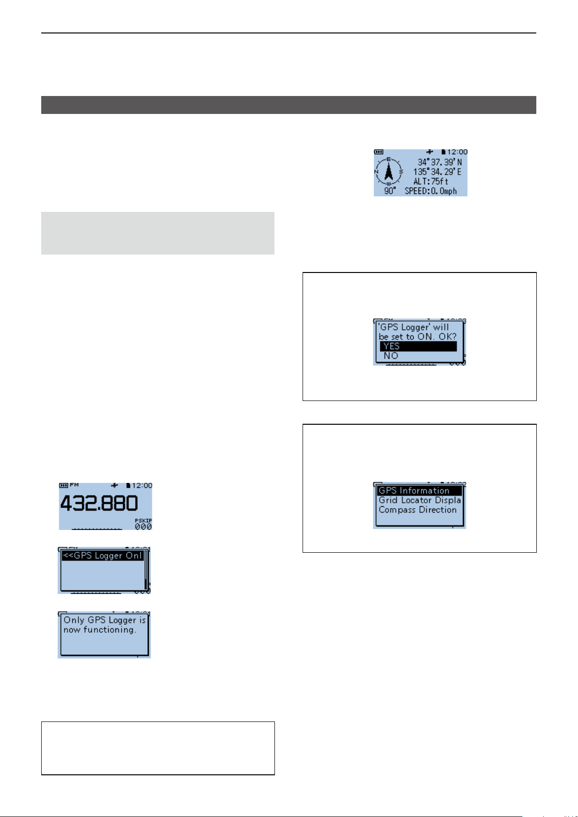
5
GPS OPERATION
GPS Logger function
D The <<GPS Logger Only>> mode
The transceiver has the exclusive GPS Logger mode
where only the GPS Logger functions.
This mode is useful when you are traveling and do not
want to use the transceiver for communication, but
you do want to use just the GPS Logger.
NOTE: In the “GPS Logger Only” mode, the GPS
Logger function is ON, but the transceiver function
is disabled, until you reboot the transceiver.
D <<GPS Logger Only>> outline
1� Insert the microSD card*.
* User supplied.
2� Confirm that the GPS receiver is receiving your
position and time. (p. 5-3)
3� Confirm that the GPS Logger function is ON.
(p. 5-28)
4� Turn ON the <<GPS Logger Only>> mode.
Completed!
You can start using the <<GPS Logger Only>> mode.
The <<GPS Logger Only>> mode screen
Compass
direction:
Heading Up
↑
Your course is indicated in degrees.
North is 0° so you are now heading
to South.
←Latitude
←Longitude
←Altitude
←Speed
TIP: When GPS Logger is set to “OFF,” the
following dialog is displayed.
(MENU > GPS > GPS Logger > GPS Logger)
To use the <<GPS Logger Only>> mode, select
<YES>.
D Setting the <<GPS Logger Only>> mode
1� Push [QUICK].
The GPS icon is
displayed.
2� Select <<GPS Logger Only>>.
• “Only GPS Logger is now functioning.” is displayed.
L You can also set the <<GPS Logger Only>> mode on
the MENU screen.
microSD card is
inserted.
↓
↓
▼
TIP: You can change the GPS Information, Grid
Locator Display, or Compass Direction settings.
In the <<GPS Logger Only>> mode, push [QUICK]
to open the Quick Menu window.
Select a setting item you want to change.
TIP: To cancel the <<GPS Logger Only>> mode
Turn OFF the transceiver then ON again.
L When the transceiver is tuned ON again, the normal
GPS Logger function is still ON.
5-32
Page 100

Section 6
VOICE MEMORY FUNCTION
NOTE: See BASIC MANUAL
Section 6 for details on how to
insert or remove a microSD card
and precautions.
Recording a QSO audio �������������������������������������������������������������������������6-2
Playing back a recorded audio ���������������������������������������������������������������6-3
Changing the QSO recorder settings �����������������������������������������������������6-4
Deleting the audio folder/le �������������������������������������������������������������������6-5
D Deleting an audio folder ������������������������������������������������������������������ 6-5
D Deleting an audio le ����������������������������������������������������������������������6-5
Viewing the le information ���������������������������������������������������������������������6-6
Viewing the microSD card memory capacity ������������������������������������������6-8
Playing back the recorded audio on the PC �������������������������������������������6-9
6-1
 Loading...