

Page 1
INSTRUCTION MANUAL
MIC
TD/RD PWR TX/RX
POWER
TRANSCEIVER
ID-1
DIGITAL
DIGITAL TRANSCEIVER
ID-1
Page 2
FOREWORD
IMPORTANT
Thank you for purchasing this Icom product. The ID-1
TRANSCEIVER
nology and craftsmanship. With proper care, this product
should provide you with years of trouble-free operation.
We want to take a couple of moments of your time to thank
you for making your ID-1 your radio of choice, and hope you
agree with Icom’s philosophy of “technology first.” Many hours
of research and development went into the design of your
ID-1.
DD
FEATURES
is designed and built with Icom’s superior tech-
❍ Current FM, Digital Voice and Data modes
available
❍ Standard PC control application via USB
terminal connection
Remote controller for current mobile trans-
❍
ceiver style operation
(optional for some versions)
❍ Standard 10BASE-T connector for data
transmission/reception
i
DIGITAL
READ ALL INSTRUCTIONS carefully and completely
before using the transceiver.
SAVE THIS INSTRUCTION MANUAL— This in-
struction manual contains important operating instructions for
the ID-1.
EXPLICIT DEFINITIONS
WORD DEFINITION
R WARNING!
CAUTION
NOTE
Icom, Icom Inc. and the logo are registered trademarks of Icom
Incorporated (Japan) in the United States, the United Kingdom, Germany, France, Spain, Russia and/or other countries.
Microsoft and Windows are registered trademarks of Microsoft Corporation in the United States and/or other countries.
All other products or brands are registered trademarks or trademarks
of their respective holders.
Personal injury, fire hazard or electric shock
may occur.
Equipment damage may occur.
Recommended for optimum use. No risk of
personal injury, fire or electric shock.
Page 3

PRECAUTION
R WARNING RF EXPOSURE! This device emits
Radio Frequency
served when operating this device. If you have any questions regarding RF exposure and safety standards please refer to the
Federal Communications Commission Office of Engineering and
Technology’s report on Evaluating Compliance with FCC Guidelines for Human Radio frequency Electromagnetic Fields
Bulletin 65).
(RF) energy. Extreme caution should be ob-
(OET
R WARNING! NEVER connect the transceiver to an
AC outlet. This may pose a fire hazard or result in an electric
shock.
R WARNING! NEVER operate the transceiver while
driving a vehicle. Safe driving requires your full attention—anything less may result in an accident.
R WARNING! NEVER transmit without an operational
antenna for 1.2 GHz operation. Transmission into a shorted or
non resonant antenna may damage the transceiver.
R WARNING for data mode operation! The
saved file(s) in the shared folder may be modified or deleted,
or unknown file(s) may be copied into the shared folder from
the connected station when the transmission inhibit is released.
Icom Inc. assume no responsibility whatsoever for any damages or lost profits resulting from opportunities for signal communications being lost because of the failure, malfunction,
poor condition, damage, or data loss of this unit or because of
such external causes as power failure. Icom also dismisses
all responsibility for demands made by a third party.
NEVER cut the DC power cable between the DC plug and
fuse holder. If an incorrect connection is made after cutting, the
transceiver may be damaged.
NEVER connect the transceiver to a power source of more
than 16 V DC. This will damage the transceiver.
NEVER connect the transceiver to a power source using re-
verse polarity. This will damage the transceiver.
NEVER expose the transceiver to rain, snow or any liquids.
The transceiver may be damaged.
NEVER operate or touch the transceiver with wet hands. This
may result in an electric shock or damage to the transceiver.
NEVER place the transceiver where normal operation of the
vehicle may be hindered or where it could cause bodily injury.
NEVER let objects impede the operation of the cooling fan on
the rear panel.
ii
Page 4

PRECAUTION
DO NOT
push the PTT when not actually desiring to transmit.
DO NOT allow children to play with any radio equipment con-
taining a transmitter.
During mobile operation,
without running the vehicle’s engine. When the transceiver’s
power is ON and your vehicle’s engine is OFF, the vehicle’s battery will soon become exhausted.
DO NOT operate the transceiver
BE CAREFUL! The transceiver will become hot when op-
erating it continuously for long periods.
AVOID using or placing the transceiver in direct sunlight or in
areas with temperatures below –10°C (+14˚F) or above +60°C
(+140˚F).
AVOID the use of chemical agents such as benzine or alcohol
when cleaning, as they can damage the transceiver’s surfaces.
USE Icom microphones only (supplied or optional). Other man-
ufacturer’s microphones have different pin assignments and may
damage the transceiver if attached.
DO NOT use the supplied CD for any other devices.
The CD is for the ID-1 only.
iii
If a connection cable is disconnected or has a loose connection during operation, an error may occur. Connect the connectors correctly, and DO NOT touch the connectors during
operation.
For the operation of PC and peripheral devices, follow the instructions provided in the manuals which come with the PC
and peripheral devices.
This device may cause signal interference when used in a domestic setting. When interference occurs, move this unit as
far as possible away from the affected device.
All copyrights associated with this manual and all intellectual
property rights associated with the hardware and software of
the ID-1 are held by Icom Inc.
Unauthorized reproduction or transmission of this manual, or
any part hereof, is prohibited.
The content of this manual, the hardware and software associated with the ID-1, and the appearance of the ID-1 are all
subject to change without notice.
For U.S.A. only
CAUTION: Changes or modifications to this device, not ex-
pressly approved by Icom Inc., could void your authority to
operate this device under FCC regulations.
Page 5
o!0
q
!2
ew
ty
ui
!1
r
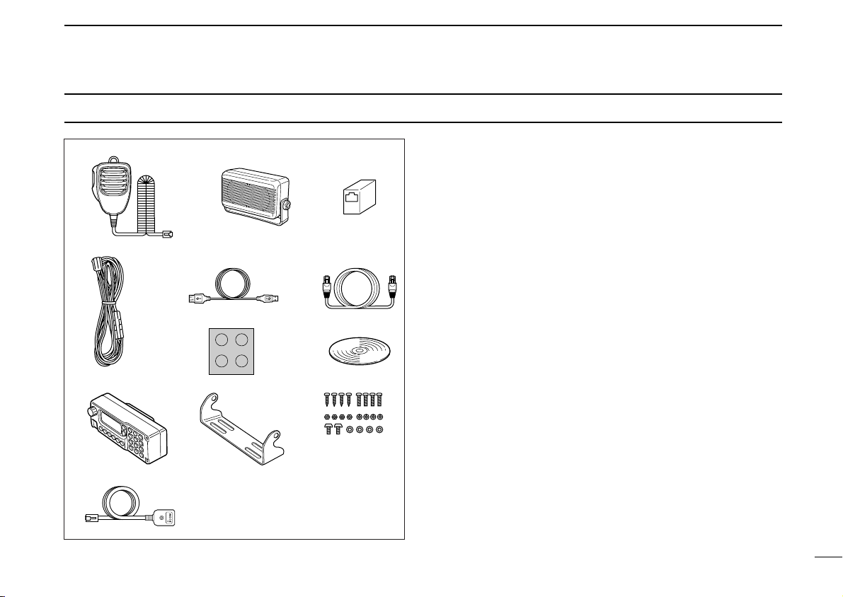
SUPPLIED ACCESSORIES
qMicrophone (HM-118N) ……………………………………1
wExternal speaker (SP-22) …………………………………1
eEthernet cable coupler ……………………………………1
rDC power cable (3 m; 9.8 ft) ………………………………1
tUSB extension cable (1.5 m; 4.9 ft) ………………………1
yEthernet cable (3 m; 9.8 ft) …………………………………1
uSelf-adhesive rubber feet …………………………………1
iApplication CD ………………………………………………1
oRemote controller (RC-24)*…………………………………1
!0Mounting bracket for remote controller* …………………1
!1Mounting screws, nuts and washers* ………………1 set
!2Mic extension cable (2.5 m; 8.2 ft)* ………………………1
*Optional for some versions.
iv
Page 6

TABLE OF CONTENTS
FOREWORD .................................................................................... i
IMPORTANT .............................................................................. i
EXPLICIT DEFINITIONS ........................................................... i
PRECAUTION ........................................................................... ii
SUPPLIED ACCESSORIES ..................................................... iv
TABLE OF CONTENTS ............................................................ v
1 PANEL DESCRIPTION .................................................. 1–12
■ Front panel ........................................................................ 1
■ Rear panel ........................................................................ 2
■ Microphones (HM-118N) ................................................... 3
■ Application screens (on PC screen) ................................. 4
■ Remote controller (RC-24; Optional for some versions) ... 9
2 INSTALLATION AND CONNECTIONS ....................... 13–17
■ Unpacking ....................................................................... 13
■ Selecting a location ......................................................... 13
■ Antenna connection ........................................................ 13
■ Power supply connections .............................................. 15
■ Microphone and speaker connections ............................ 16
■ Connecting a PC ............................................................. 17
3 DRIVER INSTALLATION ............................................. 18–29
■ Microsoft
■ Microsoft
■ Microsoft
®
Windows®XP ................................................. 18
®
Windows®98/Me ............................................ 22
®
Windows®2000 .............................................. 23
■ COM port confirmation .................................................... 28
4 APPLICATION INSTALLATION .................................. 30–31
5 BASIC OPERATION .................................................... 32–38
■ Preparation ..................................................................... 32
■ Squelch level adjustment (FM mode only) ...................... 33
v
■ Audio level adjustment .................................................... 34
■ VFO and memory mode ................................................. 34
■ Setting a frequency ......................................................... 35
■ Tuning step selection ...................................................... 37
■ Lock function (RC-24 only) ............................................. 38
■ Operating mode selection ............................................... 38
6 CALL SIGN SETTING ................................................. 39–44
■ Your call sign setting ....................................................... 39
■ Station/Repeater call sign setting ................................... 42
7 TRANSMIT AND RECEIVE— VOICE .......................... 45–54
■ FM mode operation ......................................................... 45
■ Digital voice mode operation .......................................... 45
■ When receiving a Digital call............................................ 47
■ Short message function .................................................. 49
■ Monitor function .............................................................. 53
8 REPEATER OPERATION— VOICE ............................ 55–63
■ About D-STAR system .................................................... 55
■ General ........................................................................... 56
■ Accessing an FM repeater .............................................. 57
■ Repeater tone frequency setting...................................... 59
■ Offset frequency setting .................................................. 60
■ Accessing a Digital repeater ........................................... 61
9 DATA OPERATION ...................................................... 64–70
■ General ........................................................................... 64
■ Precaution ....................................................................... 64
■ Internet access ............................................................... 65
■ Data transferring ............................................................. 68
■ Low-speed data communication ..................................... 70
Page 7

1
10MEMORY/CALL OPERATION ..................................... 71–82
■ General description ......................................................... 71
■ Memory channel selection ............................................... 71
■ Call channel selection ..................................................... 72
■ Programming a memory/call channel ............................. 74
■ Copying a memory contents ........................................... 77
■ Memory clearing ............................................................. 78
■ Programming memory name .......................................... 80
■ Memory name indication ................................................. 82
11SCAN OPERATION ..................................................... 83–89
■ Scan types ...................................................................... 83
■ Scan start/stop ................................................................ 84
■ Programming scan edge channels ................................. 85
■ Skip channel setting ........................................................ 88
■ Scan resume condition ................................................... 89
12PRIORITY WATCH........................................................ 90–91
■ Priority watch types ......................................................... 90
■ Priority watch operation .................................................. 90
13POCKET BEEP AND TONE/DIGITAL SQUELCH ...... 92–99
■ Pocket beep operation .................................................... 92
■ Tone/Digital code/call sign squelch operation ................. 96
14OTHER FUNCTIONS ............................................... 100–112
■ Set mode ...................................................................... 100
■ EMR mode operation .................................................... 107
■ Break-in communication ............................................... 109
■ S-meter squelch ............................................................ 111
■ AFC function .................................................................. 111
■ CPU reset ..................................................................... 112
15MAINTENANCE ....................................................... 113–114
■ Troubleshooting ............................................................ 113
■ Fuse replacement ......................................................... 114
16SPECIFICATIONS AND OPTIONS .......................... 115–116
■ Specifications ................................................................ 115
■ Options .......................................................................... 116
2
3
4
5
6
7
8
9
10
11
12
13
14
15
16
vi
Page 8
q
i
Front panel view
MIC
TD/RD PWR TX/RX
POWER
TRANSCEIVER
ID-1
DIGITAL
qewr t
1
PANEL DESCRIPTION
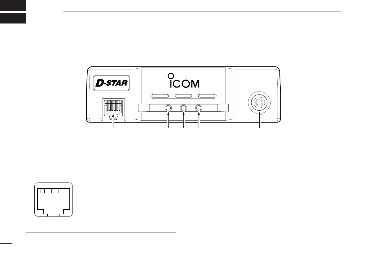
■ Front panel
qMICROPHONE CONNECTOR [MIC]
Connects the supplied microphone or the remote controller, RC-24 (optional for some versions).
q +8 V DC output (Max. 100 mA)
w Channel up/down
e Data out
r PTT
t GND (microphone ground)
y MIC (microphone input)
1
u GND
i Data IN
wDATA TRANSMIT/RECEIVE INDICATOR
Lights green while receiving; lights red while transmitting
data in data mode.
ePOWER INDICATOR
Lights while the transceiver power is turned ON.
rTRANSMIT/RECEIVE INDICATOR
Lights green while receiving; lights red while transmitting
in FM/digital voice mode.
tPOWER SWITCH [POWER]
Turns power ON and OFF when pushed for 1 sec.
Page 9
PANEL DESCRIPTION
q
ewr
t
y
1
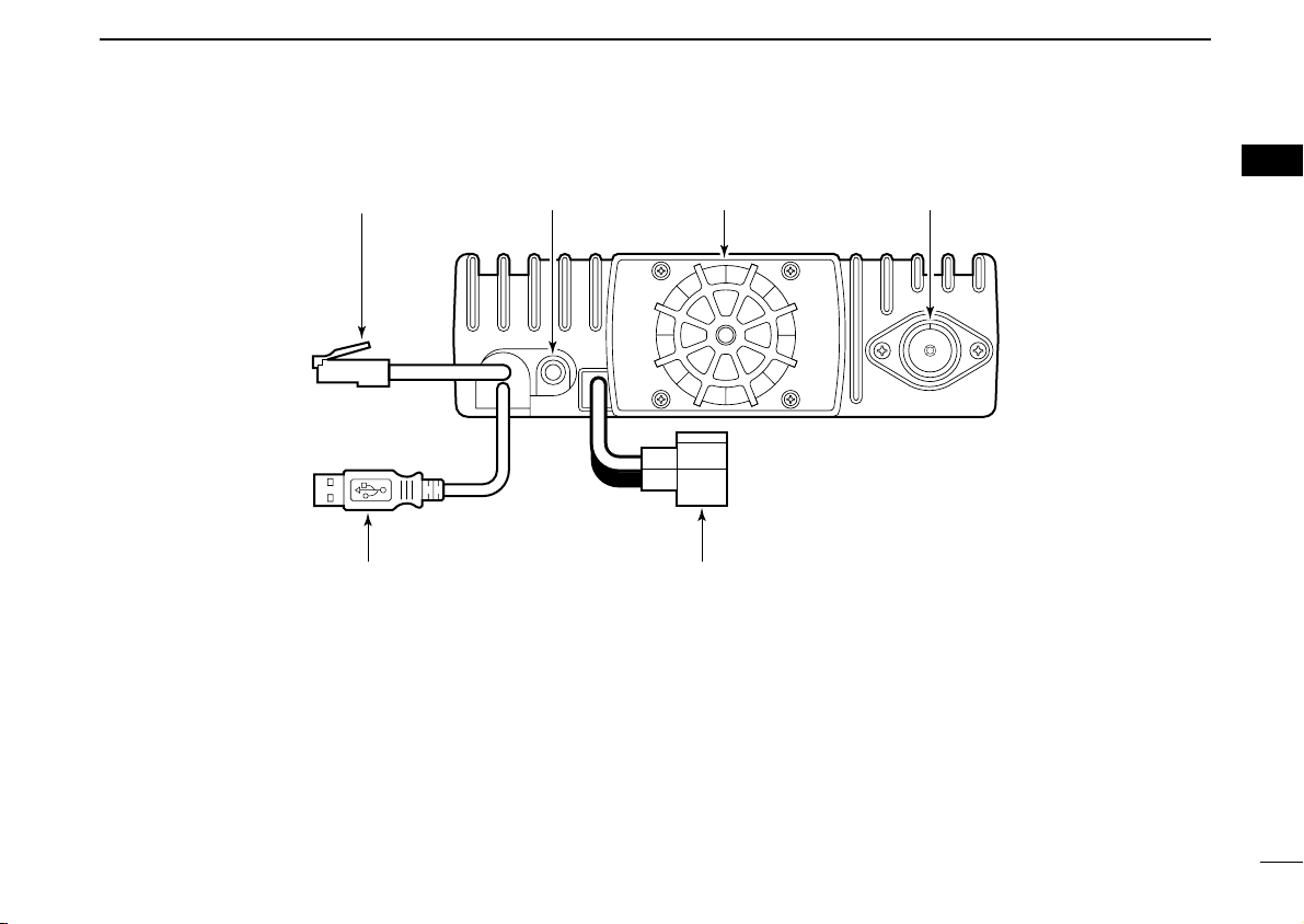
■ Rear panel
qETHERNET RECEPTACLE (p. 17)
Connects to a PC directly, or via an extension cable.
wEXTERNAL SPEAKER JACK [SP] (p. 16)
Connects the supplied (or optional) external speaker for
voice reception.
eCOOLING FAN
The fan rotates when the internal temperature of the transceiver exceeds the preset value until the temperature drops.
Also runs while receiving depending on the setting in set
mode.
r
ANTENNA CONNECTOR (p. 13)
Connects a 50 Ω antenna with a type-N connector and a
50 Ω coaxial cable.
tUSB RECEPTACLE
Connects to a PC directly or via an extension cable.
yPOWER RECEPTACLE
Accepts 13.8 V DC ±15% with the supplied DC power
cable.
(p. 17)
(p. 15)
1
2
Page 10
1 PANEL DESCRIPTION
w
q
ON
OFF
e
• HM-118N
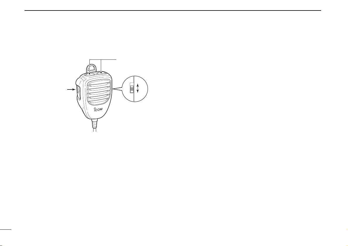
■ Microphones (HM-118N)
qPTT SWITCH
Push and hold to transmit; release to receive.
wUP/DOWN SWITCHES [UP]/[DN]
Push either switch to change operating frequency, memory channel, etc.
eUP/DN LOCK SWITCH
Slide to toggle [UP]/[DN] switches function ON and OFF.
3
Page 11
PANEL DESCRIPTION
qw e r t
!0!1!2!4!5!6!7!8@0@1 !9@2
!3
yu i o
1
■
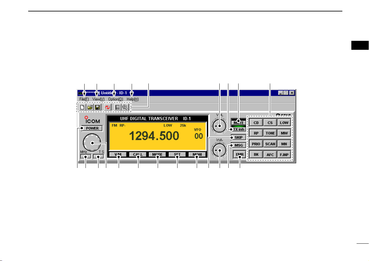
Application screens (on PC screen)
DD
Main screen
*The application screen can be seen after the application
installation. See page 30 for details.
qFILE MENU
Click to display the file menu to perform the following operation.
• Transceiver initialization
• Opening a file
• Saving (over-write or with different file name) the set con-
tents
• Reads the transceivers memory data
• Printing out the memory contents
• Quitting the application
(See NOTE on p. 6)
wVIEW MENU
Click to display the view menu to display the following
screens or selections.
• Memory channel list screen
• Set mode screen
• Font size setting
• Tool bar indication ON/OFF
• My call sign screen
1
4
Page 12

1 PANEL DESCRIPTION
eOPTION MENU
Click the option menu to display and set the following
items.
• COM port setting screen
•“Wake up power ON” function
rHELP MENU
Click the help menu to display the following screen.
• Help file
• Application version information
tTOOL BAR
The following functions can be performed by clicking one
of the desired short cut button.
• Transceiver initialization
• Opening a file
• Saving the file
• Reads the transceivers memory data
• Displays memory channel list screen
• Displays set mode screen
yAUDIO VOLUME CONTROL [VOL]
Left clicking to decrease; right clicking to increase the
audio volume level.
uTRANSMIT INHIBIT BUTTON [TX inh]
Inhibits transmission during digital mode operation.
iAUDIO MUTE BUTTON [MUTE]
Mutes the audio output.
(See NOTE on p. 6)
oFUNCTION BUTTONS
[CD] : Click to display and hide the Received call
record screen.
[CS] : Click to display and hide the Select Call Sign
screen.
[LOW] : Click to select the transmit output power from
high and low.
[RP] : Click to select repeater shifting mode from RP–,
RP+, RPS and simplex (no indication).
[TONE] : During FM mode operation
Click to select tone condition from repeater
tone ON, tone squelch ON, pocket beep function ON and no tone operation.
[DSQL] : During Digital voice mode operation
Click to select squelch condition from digital
code squelch ON, digital call sign squelch ON,
pocket beep function ON and no digital squelch
operation.
[MW] : Click to display and hide the Memory program-
ming screen.
[PRIO] : Click to start and cancel priority watch function.
[SCAN] : Click to display the scan type selection screen.
After the scan type selection, starts the scan.
[MN] : Click to switch the memory name indication ON
and OFF during memory mode operation.
[BK] : Click to start break-in communication.
[AFC] : Click to turn the automatic frequency control
function ON and OFF.
[F.INP] : Click to display and hide the Keypad screen.
5
Page 13
PANEL DESCRIPTION
1
!0EMR MODE BUTTON [EMR]
Click to enter and exit EMR mode.
!1MESSAGE BUTTON [MSG]
Click to turn the message screen indication ON and OFF.
!2SQUELCH CONTROL [SQL]
Left click to decrease; right click to increase the squelch
level.
!3SKIP BUTTON [SKIP]
During memory mode, click to turn the skip setting for the
selected memory channel ON and OFF.
!4MONITOR BUTTON [MONI]
Click to turn the monitor function ON and OFF.
While the function ON, any squelches, such as tone
squelch, are released and emits audio.
!5SET MODE BUTTON [SET]
Click to display and hide the Set mode screen.
!6OPERATING MODE BUTTON [MODE]
Click to select the operating mode from FM, digital voice
(DV) and data (DD).
!7CALL CHANNEL BUTTON [CALL]
Click to select a call channel (1–3).
!8VFO/MEMORY MODE BUTTON [V/M]
Click to switch between VFO and memory mode.
!9TUNING DIAL [DIAL]
Left click to decrease; right click to increase the operating
frequency or memory channel.
@0TUNING STEP BUTTON [TS]
Click to display the tuning step list.
After the tuning step selection, the list disappears.
@11 MHz TUNING BUTTON [MHz]
Click to turn the 1 MHz tuning ON and OFF.
While the 1 MHz tuning is selected, “Z” icon appears.
@2POWER BUTTON [POWER]
Click to turn the transceiver power ON and OFF.
Even the transceiver power is turned OFF, the control application is still running.
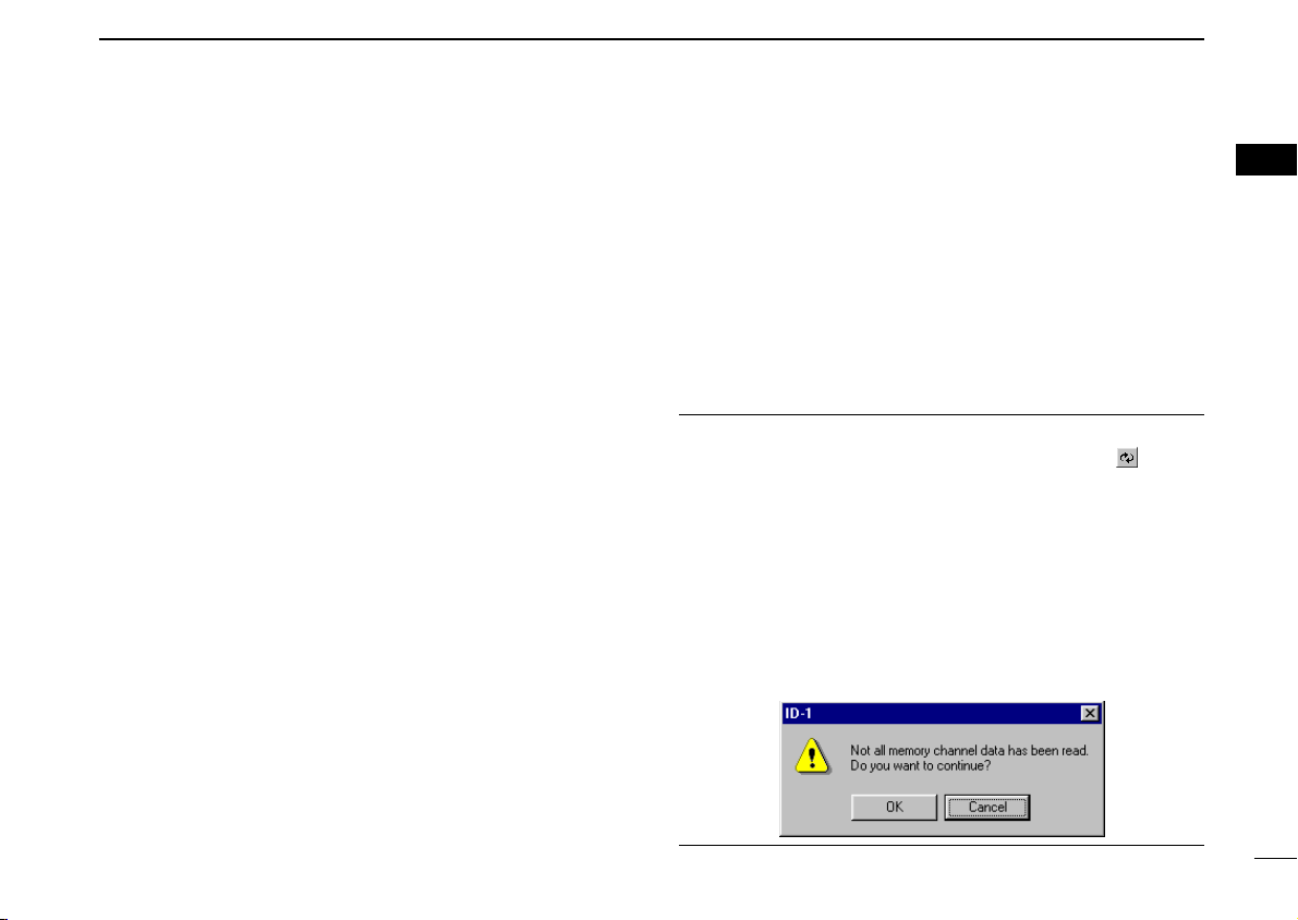
NOTE: While reading the transceiver’s memory data
While reading the transceiver’s memory data the “” button
in the tool bar will change from Black to Red arrows.
It is not recommended to save data or initialize the transceiver while the program is downloading the memory channel data. If transceiver initialization or save data buttons are
accidentally pushed, the dialog box shown below will appear.
It is recommended to click the cancel button to allow the task
of reading the transceiver to be completed. Then try the initialization or saving data. Completion of the download is indicated when the arrows change from Red to Black.
1
6
Page 14
1 PANEL DESCRIPTION
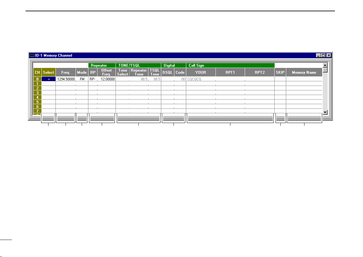
q w e r yt u i o
DD
Memory channel list screen
qCHANNEL SELECT
Select the memory channel for operation by double clicking and select “Move to this channel”.
“+” appears when the channel is selected.
wPROGRAMMED FREQUENCY
Enter the desired operating frequency.
Select the desired frequency cell, then enter the desired
frequency from the PC’s keyboard directly.
eOPERATING MODE
To select the desired operating mode, double click the
mode cell. Then click to select the desired operating mode,
FM, DV (Digital Voice) or DD (Data mode).
7
rREPEATER
Select the desired shift direction for repeater operation
from RP–, RP+, RPS and Simplex in RP cell, and enter the
desired offset frequency via the PC’s keyboard within 0 to
60 MHz range in Offset Freq. cell.
RP– : Negative shift
RP+ : Positive shift
RPS : For repeater operation in DD mode
tTONE/TSQL
Select the desired tone function from TONE, TSQL and
OFF in Tone Select cell, and select the desired tone frequency for each Repeater Tone and TSQL Tone from the
list appeared by double clicking the cell.
TONE : Repeater tone ON
TSQL : Tone squelch ON
Page 15

PANEL DESCRIPTION
1
yDIGITAL
Select the desired digital squelch function from digital code
squelch, digital call sign squelch and OFF in DSQL cell,
and enter the desired digital code number within 00 to 99
range for the digital code squelch function.
DSQL : Digital call sign squelch ON
CSQL : Digital code squelch ON
uCALL SIGN
Enter the station’s call sign that you want to call into YOUR
cell, and repeater call sign into RPT1 and RPT2 cell.
iSKIP SETTING
Turn the skip function ON (SKIP) and OFF.
When ON is set, the memory channel will be skipped during memory scan.
oMEMORY NAME
Enter the desired memory name.
Each name can have up to 10 characters.
1
8
Page 16
1 PANEL DESCRIPTION
1294.
500
00
DV RP-
q
w
e
r
t y u i o
Function display (p. 12)
Keypad (pgs. 10, 11)
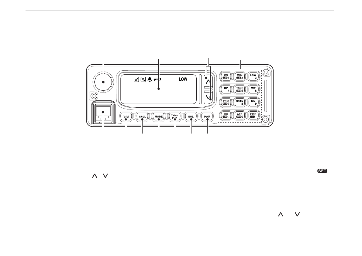
■ Remote controller (RC-24; Optional for some versions)
qTUNING DIAL [DIAL]
Selects the operating frequency (p. 35), memory channel
(p. 72), the setting of the set mode value or condition and
the scanning direction.
wUP/DOWN SWITCHES [ ]/[ ]
➥ Adjusts the audio output level. (p. 34)
➥ After pushing [SQL], adjusts squelch level. (p. 33)
eMICROPHONE CONNECTOR [MIC]
Connects the microphone, supplied with the transceiver.
rVFO/MEMORY SWITCH [V/M] (p. 34)
Push to toggle VFO and memory mode.
tCALL SWITCH [CALL] (p. 73)
Push to select and toggle call channel 1, 2 and 3.
9
yOPERATING MODE SWITCH [MODE] (p. 38)
Push to select an operating mode from FM, DV (Digital
Voice) and DD (Data mode).
uTRANSMIT INHIBIT•SET MODE SWITCH [TXinh• ]
➥ Push to inhibits a transmission during DD mode. (p. 67)
➥ Push to enter the message indication mode during DV
mode. (p. 50)
➥ Push for 0.5 sec. to enter set mode. (p. 100)
iSQUELCH SWITCH [SQL] (p. 33)
Push this switch then push either [ ] or [ ] switch to adjust the squelch level.
oPOWER SWITCH [PWR] (p. 33)
Turns power ON and OFF when pushed for 0.5 sec.
Page 17
DD
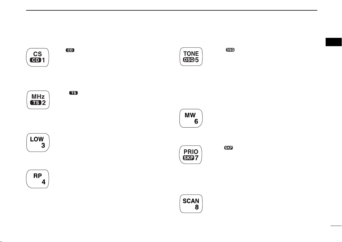
Keypad
[CS••1]
➥ Push to enter call sign select mode. (p. 40)
➥ Push for 0.5 sec. to enter received call record
indication. (p. 47)
➥ After pushing [F.INP•L], input digit “1” for op-
erating frequency or memory channel.
[MHz••2]
➥ Push to select 1 MHz tuning. (p. 35)
➥ Push for 0.5 sec. to enter tuning step select-
ing condition. (p. 37)
➥ After pushing [F.INP•L], input digit “2” for op-
erating frequency or memory channel.
[LOW•3]
➥ Push to toggle low and high transmit output
power. (p. 45)
➥ After pushing [F.INP•L], input digit “3” for op-
erating frequency or memory channel.
[RP•4]
➥ Push to toggle repeater operating mode.
(pgs. 58, 61, 67)
➥ After pushing [F.INP•L], input digit “4” for op-
erating frequency or memory channel.
PANEL DESCRIPTION
[TONE••5]
➥ FM mode: Push to turn the repeater tone,
tone squelch and pocket beep function ON
and OFF.
➥ DV Mode: Push to turn the digital call sign,
digital code squelch and pocket beep function
ON and OFF.
➥ After pushing [F.INP•L], input digit “5” for op-
erating frequency or memory channel.
[MW•6]
➥ Push to enter select memory write condition.
(p. 76)
➥ After pushing [F.INP•L], input digit “6” for op-
erating frequency or memory channel.
[PRIO••7]
➥ Push to start and stop priority watch. (p. 91)
➥ Push for 0.5 sec. to set the selected memory
channel as a skip channel during memory
mode. (p. 88)
➥ After pushing [F.INP•L], input digit “7” for op-
erating frequency or memory channel.
[SCAN•8]
➥ Push to start and stop scanning. (p. 84)
➥ After pushing [F.INP•L], input digit “8” for op-
erating frequency or memory channel.
1
1
10
Page 18
1 PANEL DESCRIPTION
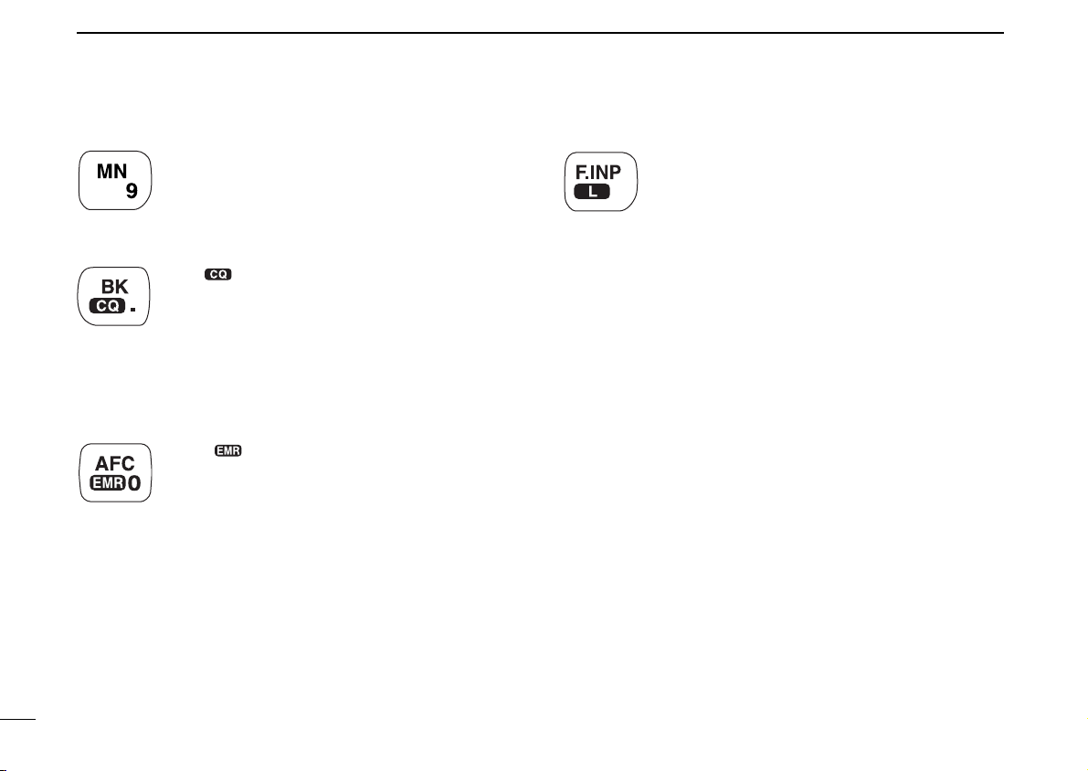
[MN•9]
➥ Push to select memory name or frequency in-
dication during memory mode. (p. 82)
➥ After pushing [F.INP•L], input digit “9” for op-
erating frequency or memory channel.
[BK••.]
➥ Push to enable a break call during digital
voice operation. (p. 110)
➥ Push for 0.5 sec. to select “CQ” as a call sign
during digital voice operation. (p. 46)
➥ After pushing [F.INP•L], selects previous
“MHz” digits frequency for operating fre-
quency. (p. 36)
[AFC••0]
➥ Push to turn the AFC (Automatic Frequency
Control) function ON and OFF. (p. 111)
➥ Push for 1.5 sec. to turn the EMR mode ON,
and push for 0.5 sec. to turn the function OFF
during digital voice mode operation. (p. 108)
➥ After pushing [F.INP•L], input digit “0” for op-
erating frequency or memory channel.
[F.INP•L]
➥ Push to enable the direct frequency or mem-
ory channel number input.
➥ Push for 0.5 sec. to turn the RC-24 key lock
function ON and OFF. (p. 38)
11
Page 19
DD
1294.500
FM RP-
M00
qiwert y u
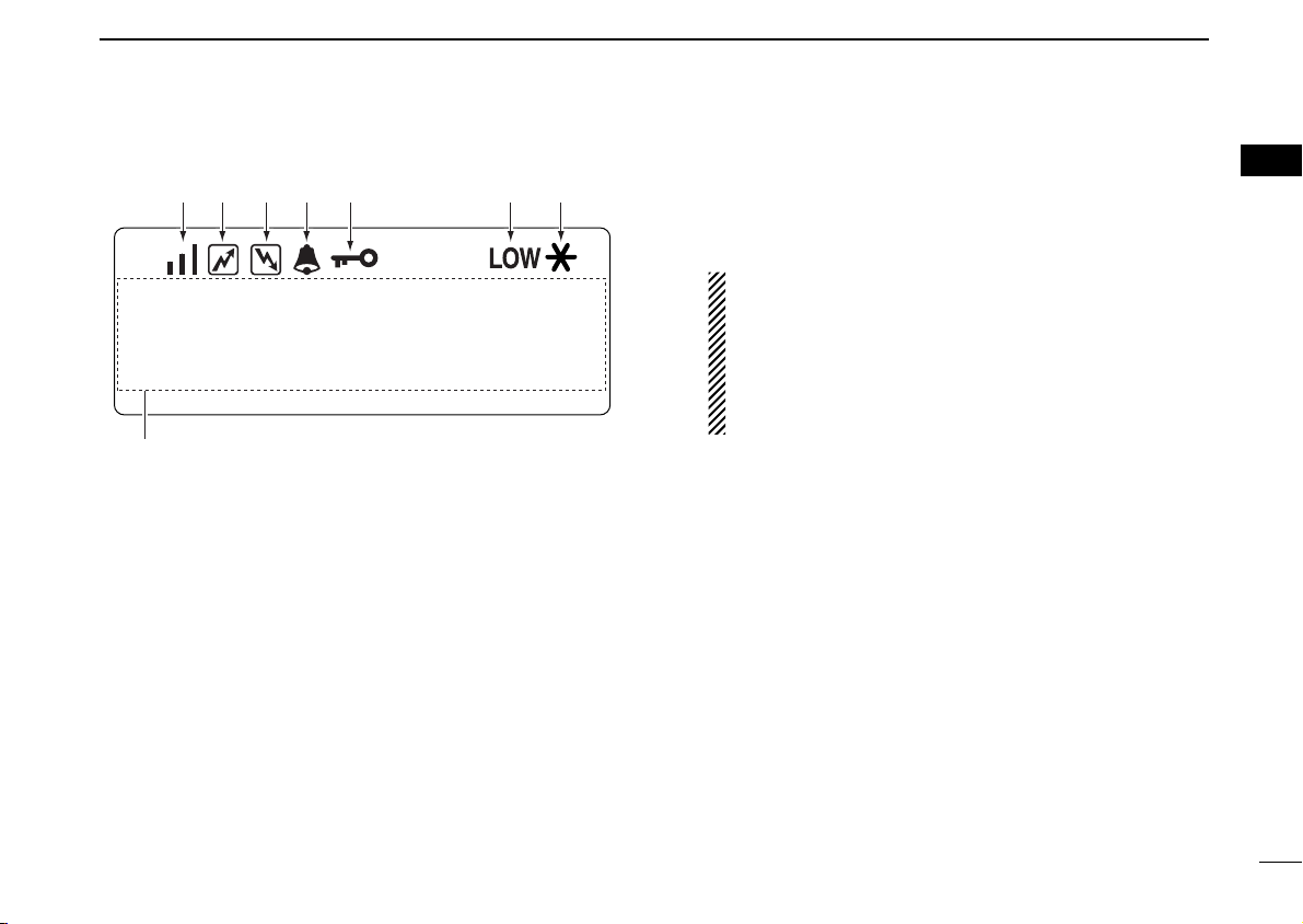
Function display
qS/RF INDICATORS
➥ Shows the relative signal strength while receiving sig-
nals in 3 steps.
➥ Shows the output power level while transmitting.
wTRANSMIT INDICATOR
Appears while transmitting.
PANEL DESCRIPTION
eBUSY INDICATOR
Appears when a signal is being received, the squelch is
open, or the monitor function is activated.
NOTE: If this indicator appears and no audio is heard it
is one of several conditions.
1. Verify audio level setting.
2. Verify connection of external speaker.
3. FM: Signal coming in, but does not match TSQL.
Digital Voice: Incoming signal does not match call
signs in the call sign squelch list.
rPOCKET BEEP INDICATORS (p. 94)
Appears when the pocket beep function is activated.
tLOCK INDICATOR (p. 38)
Appears when the lock function is in use.
yLOW POWER INDICATOR
Appears when low output power is selected.
uMESSAGE INDICATOR
Blinks when a message is received. (p. 51)
iMULTI-FUNCTION INDICATOR
Shows variety of information, such as the operating frequency, operating mode, memory names, set mode item
and conditions.
1
1
12
Page 20
2
ID-1
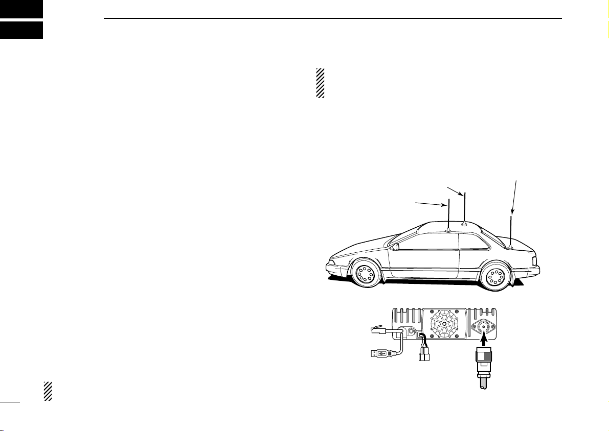
To antenna
Roof-mount antenna
(Drill a hole or use a magnetic mount.)
Gutter-mount antenna
Trunk-mount
antenna
INSTALLATION AND CONNECTIONS
■ Unpacking
After unpacking, immediately report any damage to the delivering carrier or dealer. Keep the shipping cartons.
For a description and a diagram of accessory equipment included with the ID-1, see ‘Supplied Accessories’ on p. iv of
this manual.
■ Selecting a location
Select a location for the transceiver that allows adequate air
circulation, free from extreme heat, cold, or vibrations, and
away from TV sets, TV antenna elements, radios and other
electromagnetic sources.
■ Antenna connection
For radio communications, the antenna is of critical importance, along with output power and sensitivity. Select antenna(s), such as a well-matched 50 Ω antenna, and feedline.
1.5:1 or better of Voltage Standing Wave Ratio (VSWR) is
recommended for your desired band. Of course, the transmission line should be a coaxial cable.
NOTE: There are many publications covering proper antennas and their installation. Check with your local dealer
for more information and recommendations.
• Antenna location for mobile operation
To obtain maximum performance from the transceiver, select
a high-quality antenna and mount it in a good location. A nonradial antenna should be used when using a magnetic mount.
13
CAUTION: Protect your transceiver from lightning by using
a lightning arrestor.
Page 21
INSTALLATION AND CONNECTIONS
2
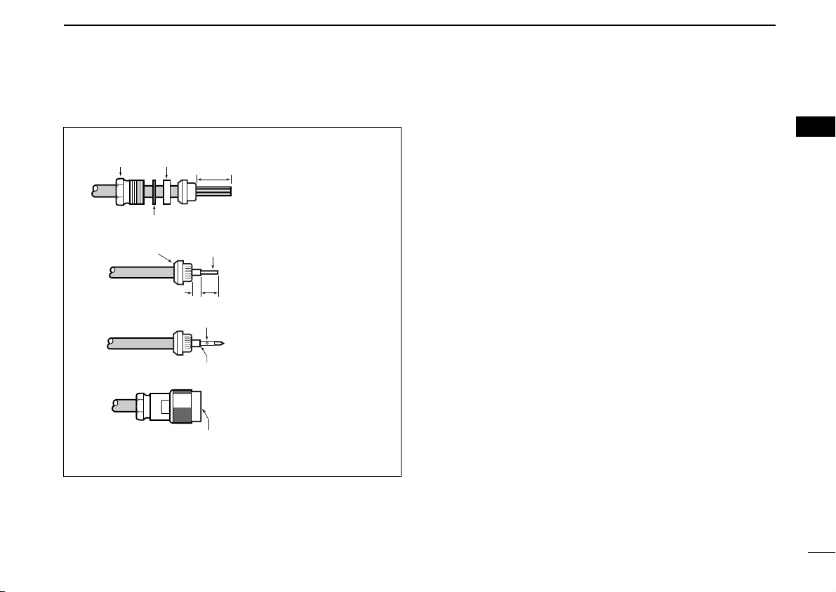
Type-N CONNECTOR INSTALLATION EXAMPLE
Nut Rubber gasket
q
Washer
w
Clamp
e
r
Be sure the center conductor is
the same height as the plug body.
15 mm ≈19⁄32 in 6 mm ≈1⁄4 in 3 mm ≈1⁄8 in
3 mm
15 mm
Center
conductor
6 mm
Solder hole
No space
Slide the nut, washer,
rubber gasket and clamp
over the coaxial cable,
then cut the end of the
cable evenly.
Strip the cable and fold the
braid back over the clamp.
Soft solder the center
conductor. Install the
center conductor pin and
solder it.
Carefully slide the plug
body into place aligning the
center conductor pin on the
cable. Tighten the nut onto
the plug body.
2
14
Page 22
2 INSTALLATION AND CONNECTIONS
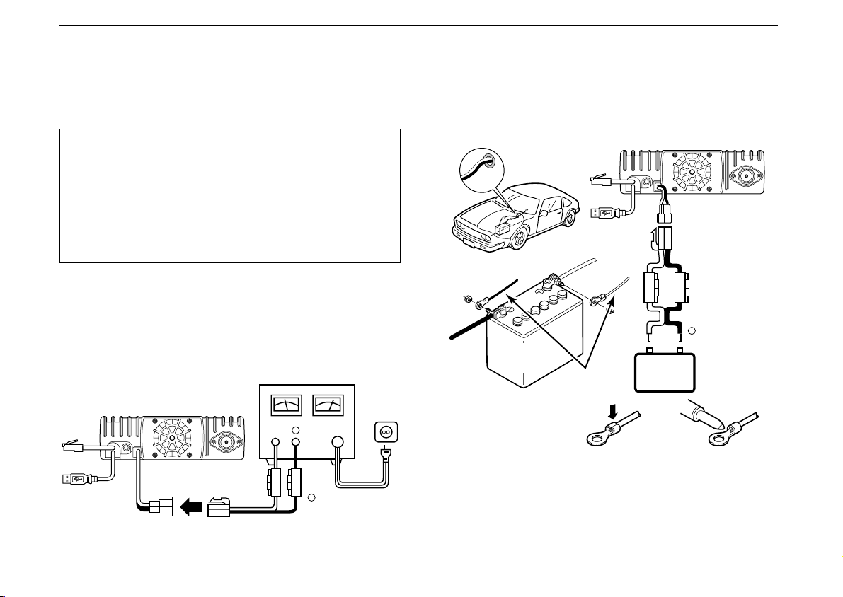
12 V
Grommet
NOTE:
Use terminals for the
cable connections.
WARNING!
NEVER
remove the
fuse holders.
Crimp
Solder
12 V
battery
Supplied
DC power cable
+ red
ID-1
_ black
red⊕
black
−
DC power
supply 13.8 V
AC
outlet
Fuses
15 A
Black
Red⊕
−
⊕
−
ID-1
■ Power supply connections
CAUTION: Before connecting the DC power cable,
check the following important items. Make sure:
• The [POWER] switch is OFF.
• Output voltage of the power source is 12–15 V when you
use a power supply.
• DC power cable polarity is correct.
Red : positive + terminal
Black : negative _ terminal
Use a DC power supply with a 10 A capacity and above when
operating the transceiver with AC power. Refer to the diagrams below.
• Connecting to a DC power supply
15
• Connecting to a vehicle battery
Page 23
INSTALLATION AND CONNECTIONS
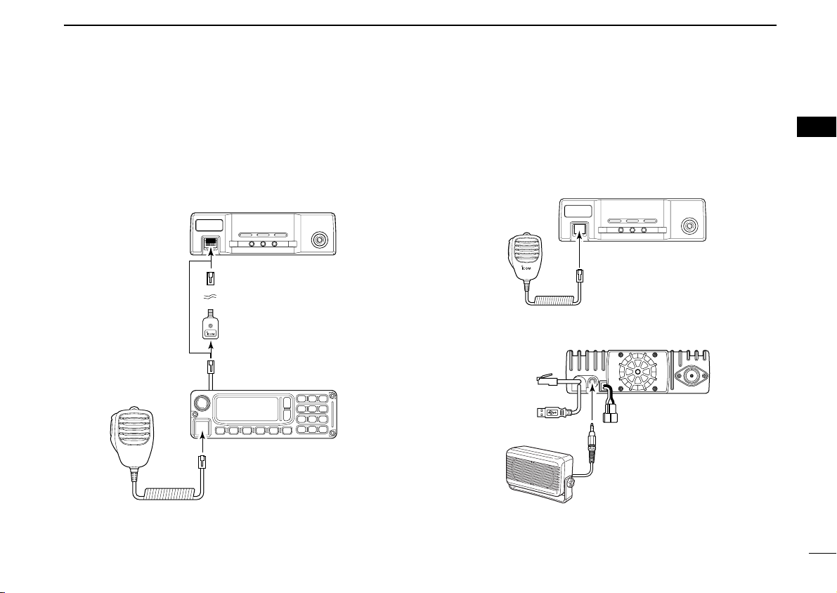
ID-1
SP-22
to [SP]
ID-1
to [MIC]
ID-1
Mic extension
cable, OPC-647
(2.5 m; 8.2 ft)
RC-24
to [MIC]
to [MIC]
■ Microphone and speaker connections
Connect the supplied microphone to the [MIC] connector on
the remote controller (RC-24) or front panel and the speaker
to the [SP] connector on the rear panel as follows.
• Microphone connection through RC-24 • Microphone connection without RC-24
• Speaker connection
2
2
16
Page 24
2 INSTALLATION AND CONNECTIONS
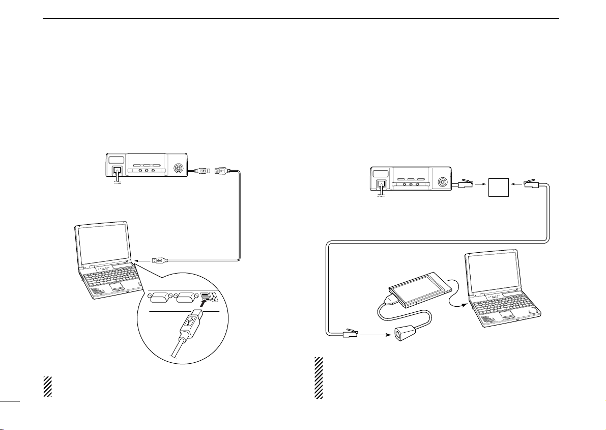
ID-1
PC
Use the supplied OPC-1069, Ethernet cable (3 m; 9.8 ft),
and the cable coupler for extension, if desired.
to Ethernet
port
to card
slot
Cable coupler
Ethernet card
ID-1
PC
Use the supplied
USB extension cable,
OPC-1127
(1.5 m; 4.9 ft),
if desired.
to USB
port
■ Connecting a PC
DD
PC connection for control
USB (Universal Serial Bus) cable is used for the connection
between the ID-1 and a PC.
An USB extension cable, OPC-1127 (1.5 m; 4.9 ft), is supplied with the transceiver for extended connection.
NOTE: When connecting the ID-1 and the PC through an
17
USB hub, use the self-powered type.
DD
PC connection for data operation
Ethernet cable connection is additionally required for the data
operation.
Connect the Ethernet receptacle to the Ethernet port on your
PC directly or through the supplied extension cable with the
cable coupler, if desired.
NOTE: When no Ethernet port is available with your PC,
install an Ethernet card and it’s driver before connecting
the ID-1. Ask your local computer dealer for details about
installing a Ethernet card to your computer.
Page 25
The displayed dialog boxes or indications may differ
Click
Select
slightly from the following instructions according to your
system conditions, or environment.
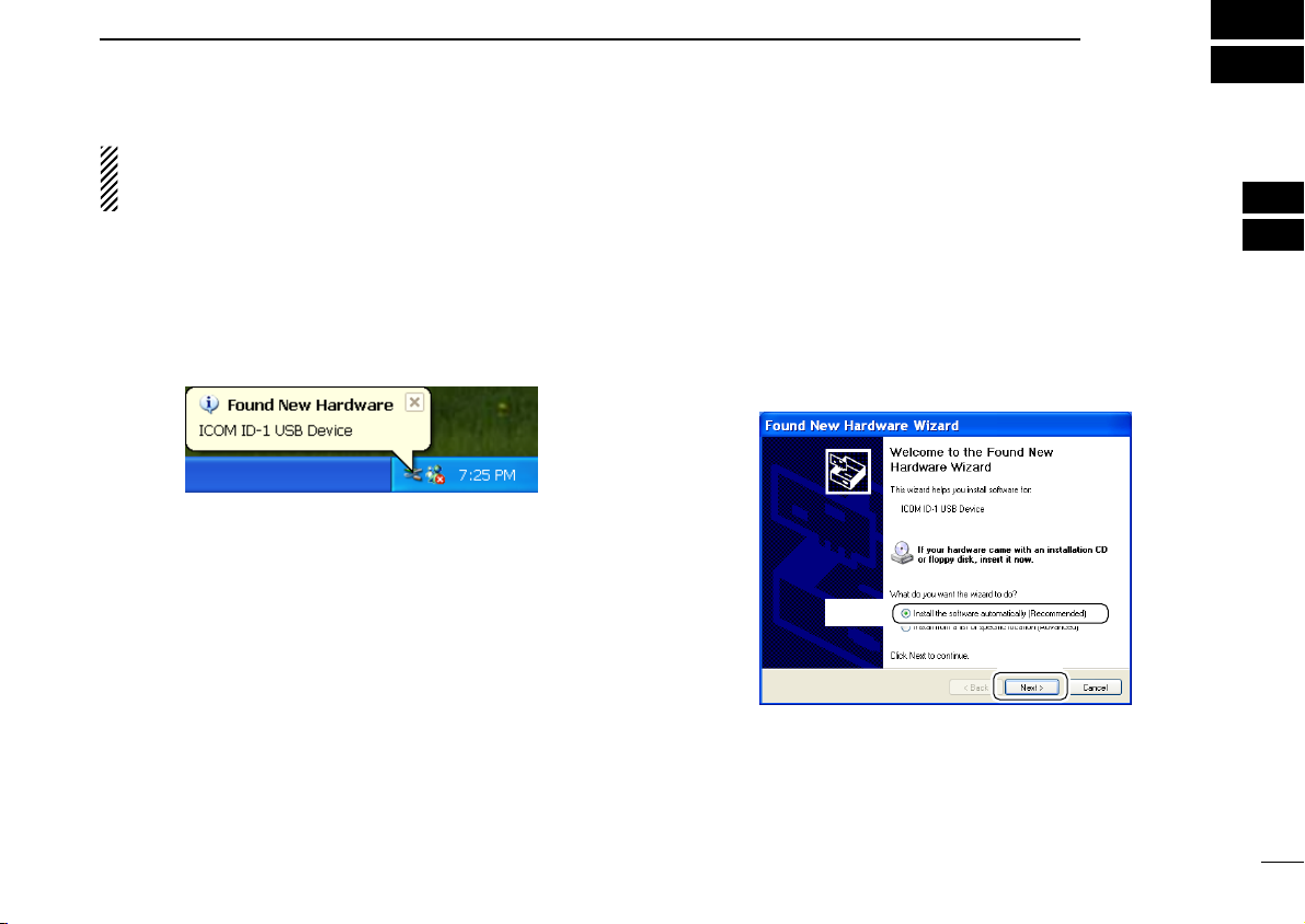
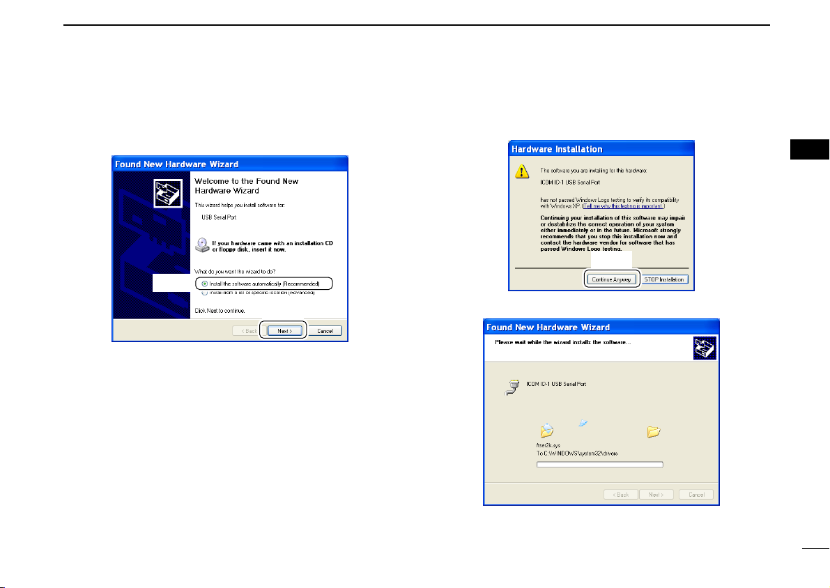
■ Microsoft®Windows®XP
qConnect the ID-1 to the desired USB port.
• Push [POWER] to turn the power ON.
•“Found New Hardware” appears as below.
DRIVER INSTALLATION
wThe “Found New Hardware Wizard” will come up as below.
Insert the supplied CD into the CD drive, select “Install the
software automatically (Recommended),” then click
[Next>].
3
2
3
18
Page 26
3 DRIVER INSTALLATION
Click
Click
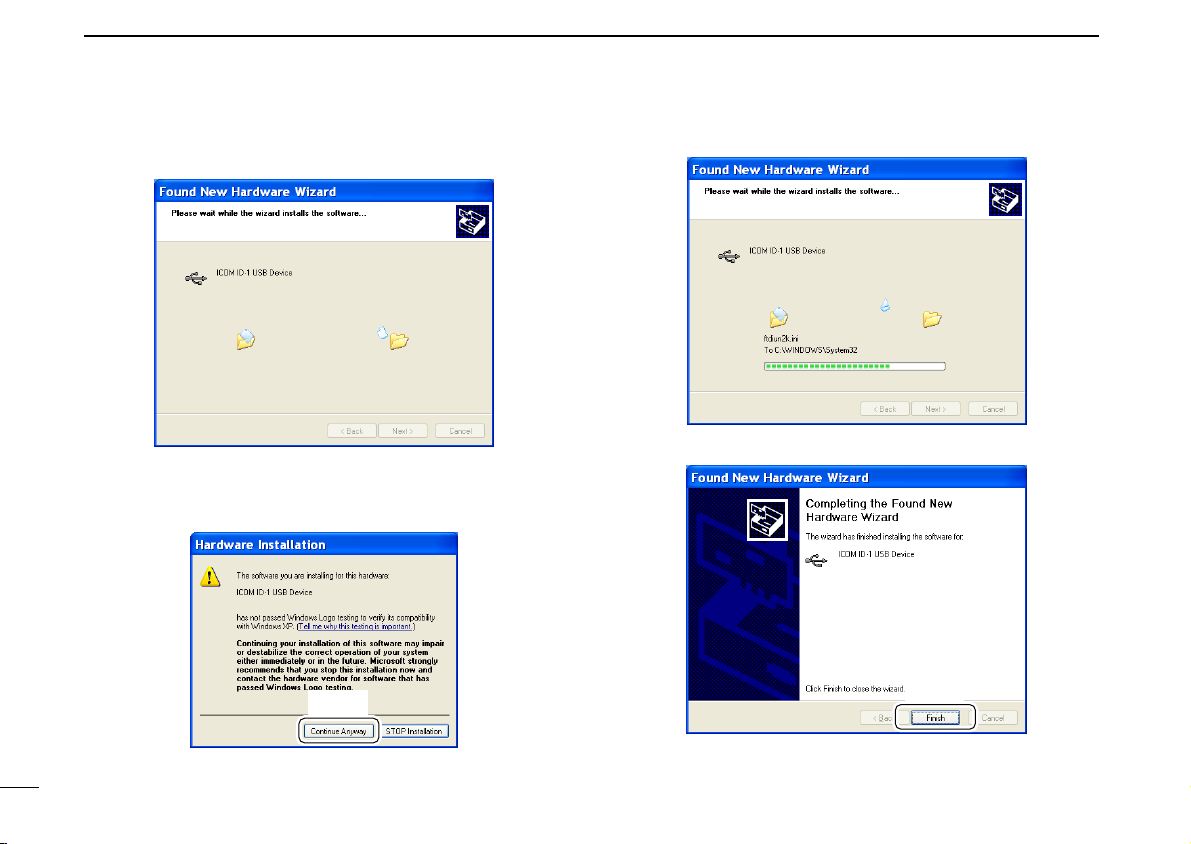
eThe wizard starts searching for the driver and shows the
dialog below during search.
rAfter the driver is found, the “Hardware Installation” dialog
box appears as below.
Click [Continue Anyway] to start the installation.
tWindows starts installing the USB driver.
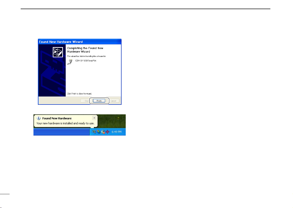
yAfter the installation is completed, click [Finish].
19
Page 27
DRIVER INSTALLATION
Click
Click
Select
3
uThe “Found New Hardware Wizard” will come up again to
install the USB serial port driver.
Select “Install the software automatically (Recommended),”
then click [Next>].
iAfter the driver is found, the “Hardware Installation” dialog
box appears as below.
Click [Continue Anyway] to start the installation.
3
oWindows starts installing the USB driver.
20
Page 28
3 DRIVER INSTALLATION
Click
!0After the installation is completed, click [Finish].
!1After clicking [Finish], the dialog appears as below.
!2Eject the CD.
• Rebooting the PC is recommended.
21
Page 29
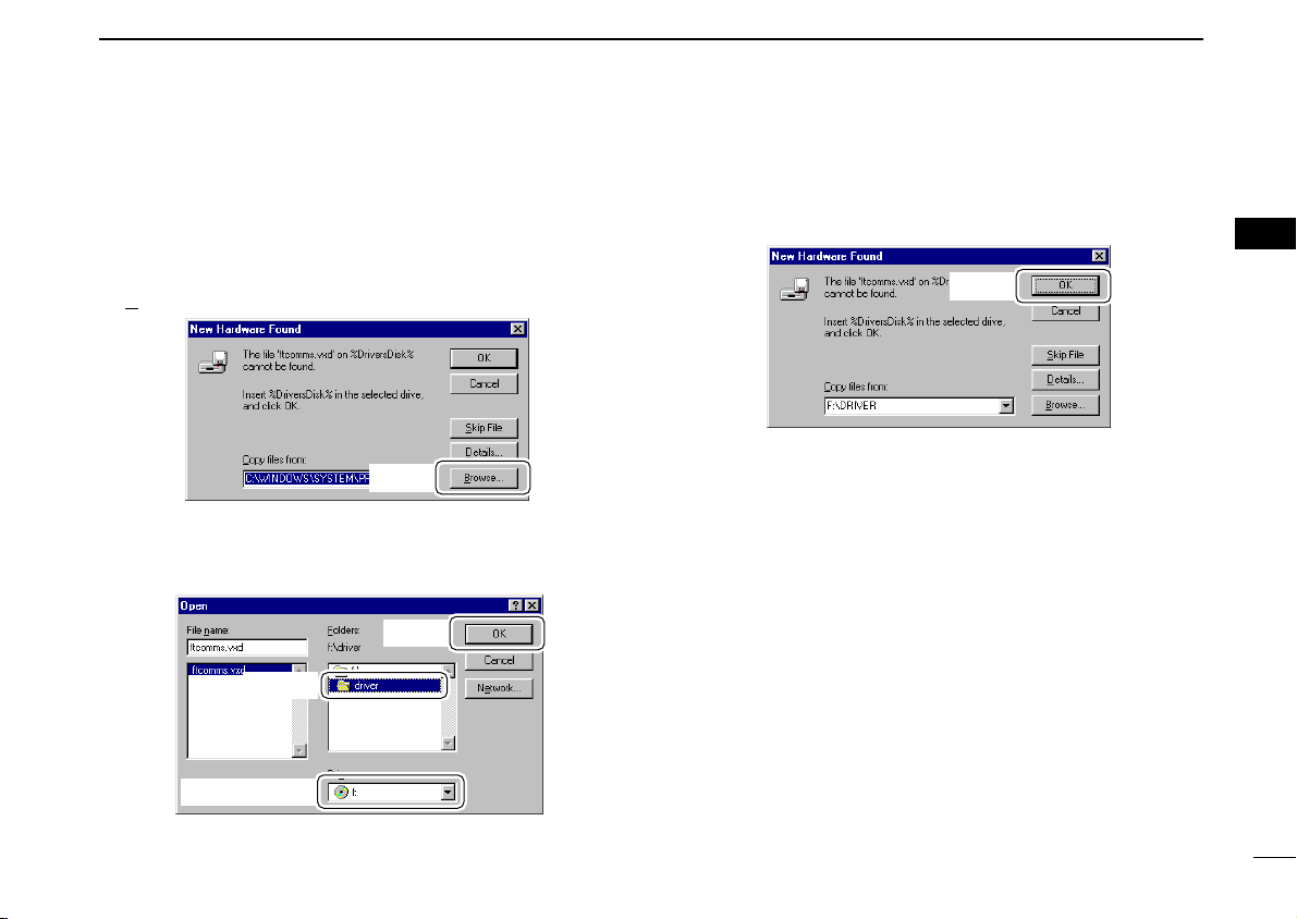
■ Microsoft®Windows®98/Me
Click
e Click
q Click to select
w Select
Click
DRIVER INSTALLATION
3
qConnect the ID-1 to the desired USB port.
• Push [POWER] to turn the power ON.
•“New Hardware is found” dialog box appears.
wThe “New Hardware Found” will come up as below. Click
[B
rowse...].
eInsert the supplied CD into the drive.
rClick [Z] to select the appropriate CD-ROM drive then click
“Driver” folder. After the driver is found, click [OK].
tClick [OK].
• The driver installation starts.
yAfter the installation, eject the CD.
• Rebooting the PC is recommended.
3
22
Page 30
3 DRIVER INSTALLATION
Click
Select
Click
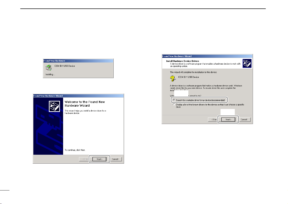
■ Microsoft®Windows®2000
qConnect the ID-1 to the desired USB port.
• Push [POWER] to turn the power ON.
•“Found New Hardware” dialog box appears below.
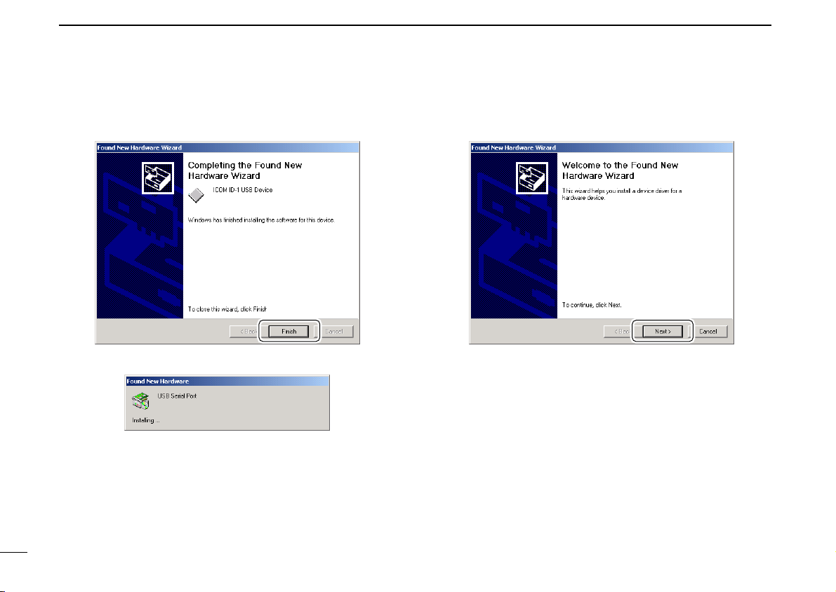
wThe “Found New Hardware Wizard” will come up as below.
Click [Next>].
eSelect “Search for a suitable driver for my device (recom-
mended),” then click [Next>].
23
Page 31

DRIVER INSTALLATION
Click
Click
Select
3
rSelect “CD-ROM drives,” and insert the supplied CD into
the CD drive, then click [Next>].
tWhen the driver is found, the following dialog is displayed.
Click [Next>] to start the installation.
NOTE: When the appropriate driver is not found, a different dialog is displayed. In such case, click [<Back], select
“Specify a location,” click [Next>], then type “D:\driver” in
the text box to select the “Driver” folder in the CD (if CD
drive is D).
3
24
Page 32
3 DRIVER INSTALLATION
Click
Click
yAfter the installation is completed, click [Finish].
uThe “Found New Hardware” wizard appears again.
iClick [Next>].
25
Page 33

DRIVER INSTALLATION
Click
Select
Click
Select
3
oSelect “Search for a suitable driver for my device (recom-
mended),” then click [Next>].
!0Select “CD-ROM drives,” then click [Next>].
3
26
Page 34

3 DRIVER INSTALLATION
Click
Click
!1When the driver is found, the following dialog is displayed.
Click [Next>] to start the installation.
NOTE: When the appropriate driver is not found, a different dialog is displayed. In such case, click [<Back], select
“Specify a location,” click [Next>], then type “D:\driver” in
the text box to select the “Driver” folder in the CD (if CD
drive is D).
!2After the installation is completed, click [Finish].
!3Eject the CD.
• Rebooting the PC is recommended.
27
Page 35

DRIVER INSTALLATION
Click
Click
3
■ COM port confirmation
After the driver installation, confirm the driver availability and
the port number are recommended.
In this section, screen shots of Windows XP are used for instruction example. However, the instructions are similar to another operating systems, Windows 98, Me and 2000.
qBoot up the Windows.
wSelect the “Control Panel” in the Start menu.
• Control panel appears as shown in the next step below.
eClick the “Performance and Maintenance.”
• Performance and Maintenance menu appears.
tClick the [Device Manager].
3
• Device Manager screen appears as below.
rClick the “System,” then click the “Hardware” tab in the dis-
played System Properties screen.
28
Page 36

3 DRIVER INSTALLATION
Confirm the USB serial port availability and the COM port
number.
(In this example, the USB serial port number is “4.”)
Click
yClick “” of the “Ports (COM & LPT)” to display the usable
COM port and the port number.
uConfirm the USB serial port availability and the COM port
number.
• The COM port number is used for the COM port setup. (p. 32)
iClose the Device Manager, System Properties screen and
then Control panel.
29
Page 37

APPLICATION INSTALLATION
Click
Double click
4
qInsert the CD into the CD drive.
wOpen the CD drive contents via “My computer” or “Win-
dows Explorer.”
•“Driver” and “ID1” folders are available.
eDouble click “Setup.exe” file in “ID1” folder.
• The “InstallShield®Wizard” starts preparing the installation.
rAfter the preparation, the following dialog is displayed.
Click [Next>].
3
4
30
Page 38

4 APPLICATION INSTALLATION
Click
Click
tConfirm the location, then click [Next>] to start the installa-
tion.
• Click [Browse...] then type the desired location if you specifying
the installation location.
yAfter the installation is completed, click [Finish].
uEject the CD.
• The ID-1 shortcut icon is created on the desktop.
• Rebooting the PC is recommended.
31
Page 39
■ Preparation
Click
Enter the appropriate
port number
(within 1–256)
Click
Click
BASIC OPERATION
5
DD
Turing power ON/OFF from the application
qBoot up Windows.
wStart the ID-1 application by double clicking the icon on the
desktop, or select “ID-1” in the program menu.
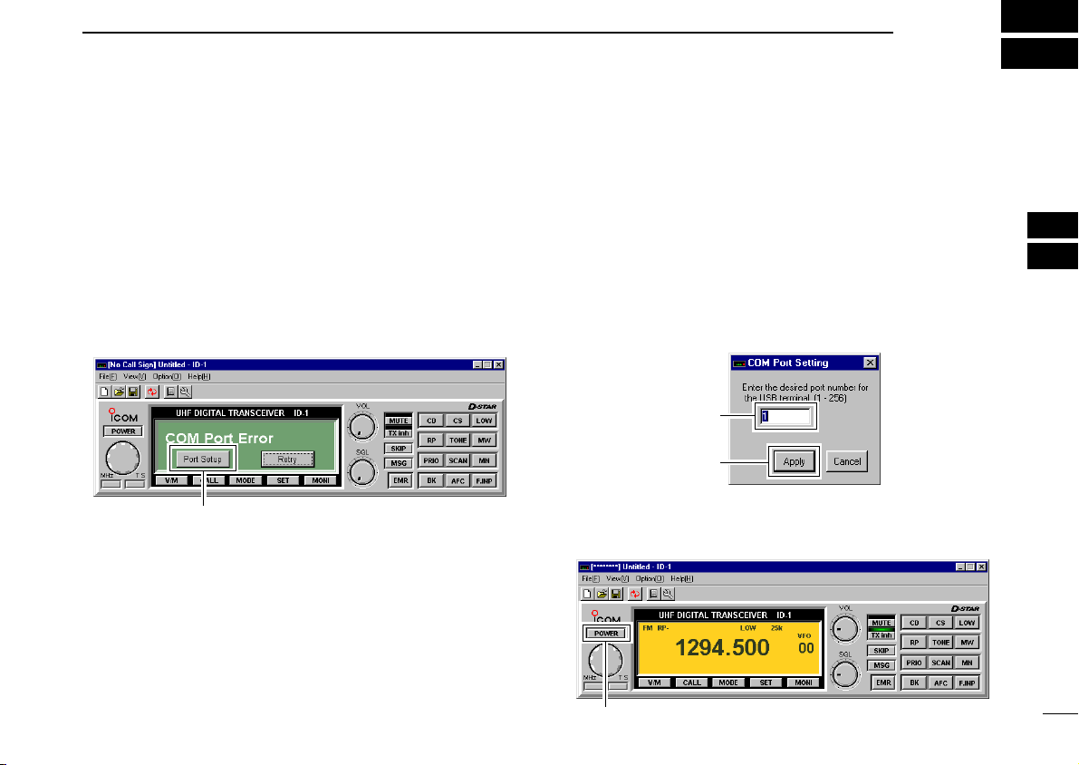
• ID-1 main screen appears and “COM Port Error” may be dis-
played for 1st time as below.
eClick [Port Setup].
• COM Port Setup dialog box appears.
rEnter the appropriate COM port number from the PC’s key-
board within 1–256 range, then click [Apply].
• See pages 28, 29 for how to confirm the COM port number.
• The transceiver power comes up and the default frequency will
be displayed on the main screen when the correct port number is
entered.
• Once the COM port is set, this operation will not be necessary.
• When using multiple radios with the same Laptop, changing the
COM Port number will be required each time a new radio is connected to the computer.
tClick [POWER] to turn the power OFF.
• The transceiver power can also be turned OFF by pushing
[POWER] on the ID-1 front panel.
4
5
32
Page 40
5 BASIC OPERATION
[SQL]
[ ]
[ ]
Right click to increase; Left click to decrease
[PWR]
■ Squelch level adjustment
yTo quit the application, select “Exit(X
click “” button on the top right corner of the screen.
• The application cannot be quit by turning OFF the transceiver’s
power only. And also, the transceiver power is still ON even the
application is quit without turning OFF with [POWER].
)” in the file menu, or
Hint!
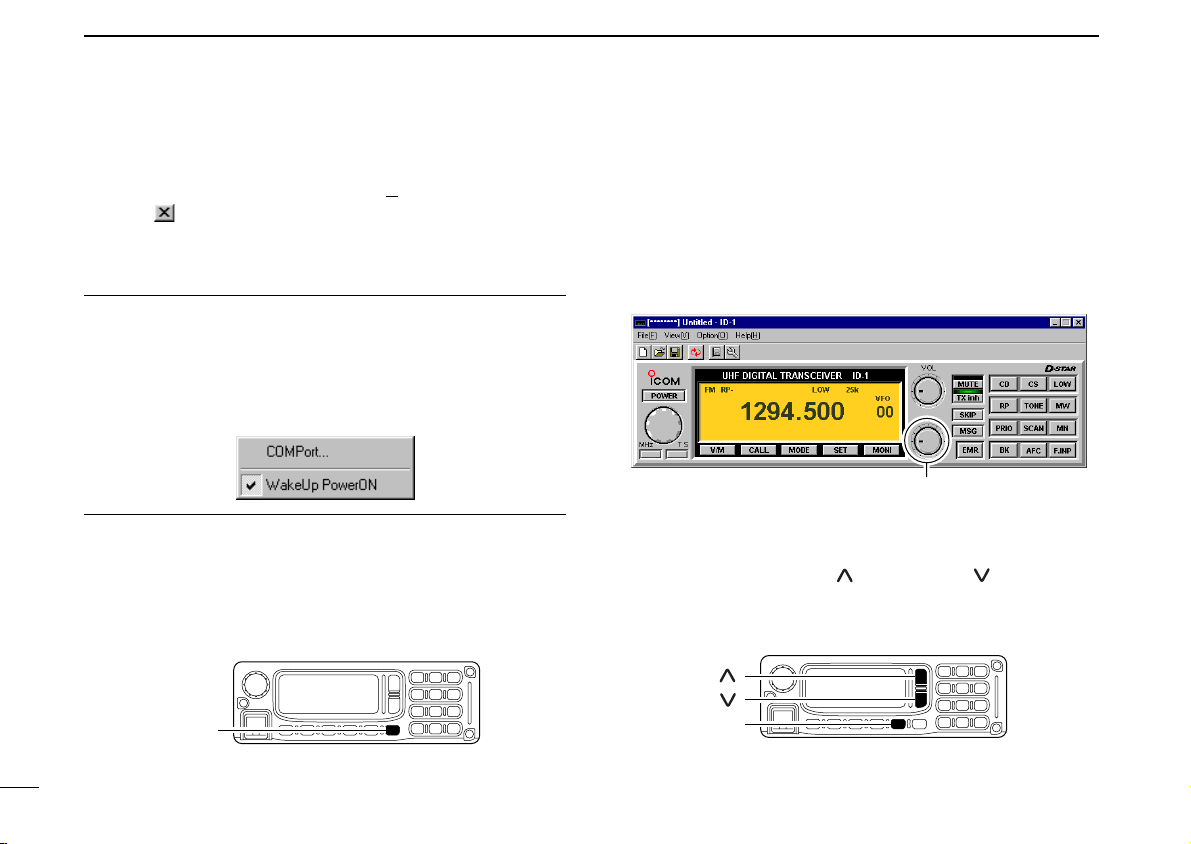
The ID-1 has “WakeUp PowerON” function, which automati-
cally powers ON when the application is started up.
To turn the function ON and OFF, select “Wakeup PowerON”
item in option menu. “✔” appears when the function is activated.
DD
Turing power ON/OFF from the RC-24
➥ Push [PWR] to turn the power ON.
• Pushing [POWER] on the ID-1 front panel also turns power ON.
• Push [PWR] (or [POWER] on the ID-1 front panel) for 0.5 sec. to
turn the power OFF.
(FM mode only)
DD
From the application
➥ Set the pointer on [SQL] control then; right click to in-
crease, left click to decrease the squelch level.
• Set [SQL] within 9–12 o’clock position is recommended.
DD
From the RC-24
➥ Push [SQL], then push [ ] to increase, [ ] to decrease
the squelch level.
•“SQL” and set level appear on the function display.
• Set the squelch level within 9 to 19 is recommended.
33
Page 41
BASIC OPERATION
[V/M]
Click “VFO” or “MEMO” appears
[ ]
[ ]
Right click to increase; Left click to decrease
5
■ Audio level adjustment
DD
From the application
qOpen the squelch.
• The monitor function is available to open the squelch without adjusting [SQL] level— click [MONI] to open and close the squelch.
wSet the pointer on [VOL] control then; right click to in-
crease, left click to decrease the audio level.
DD
From the RC-24
➥ Push [ ] to increase, [ ] to decrease the audio level.
•“VOL” and set level appear on the function display.
• The audio level can be adjusted within 0 (no audio) to 32 (max.
audio) levels.
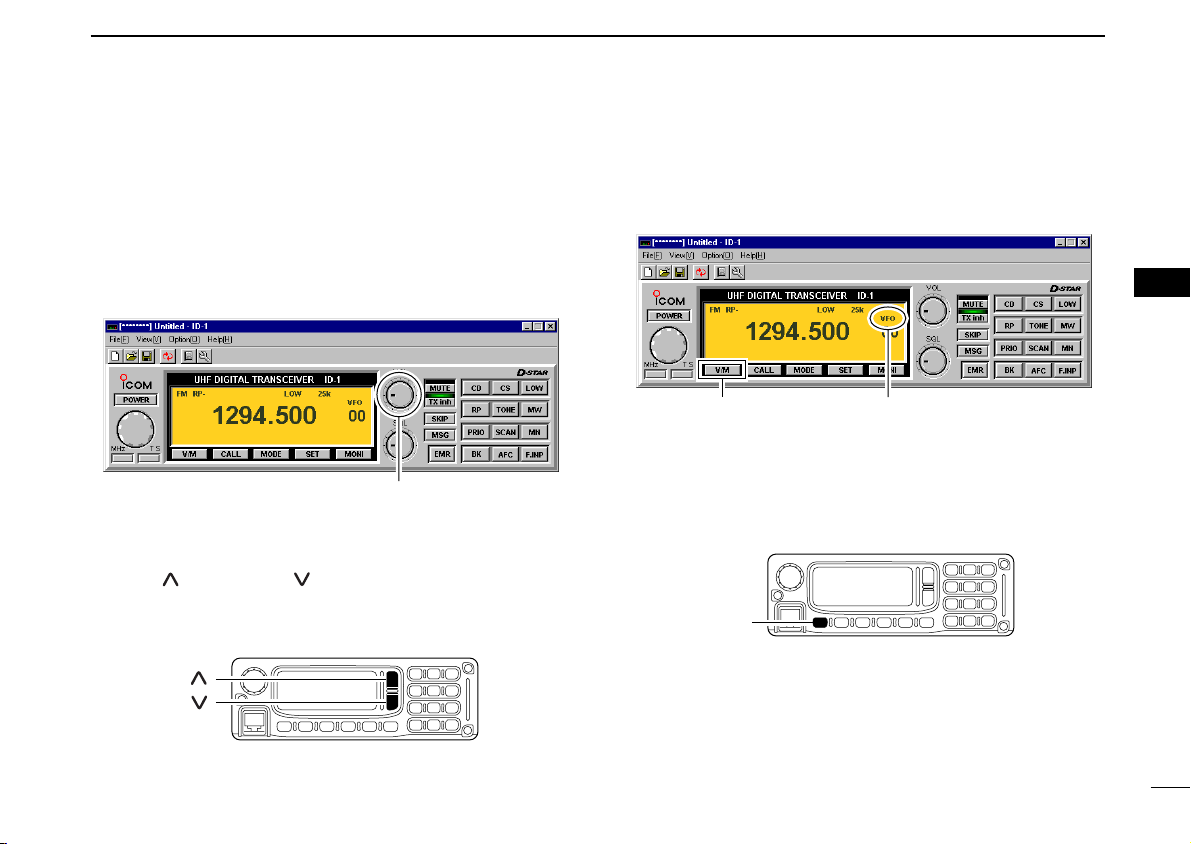
■ VFO and memory mode
DD
From the application
➥ Click [V/M] to toggle between VFO and memory mode.
DD
From the RC-24
➥ Push [V/M] to toggle between VFO and memory mode.
•“M” appears besides memory channel number when memory
mode is selected.
5
34
Page 42

5 BASIC OPERATION
[MHz• •2]
[DIAL]
Right click to increase; Left click to decrease
■ Setting a frequency
DD
Using the application tuning dial
qSet the pointer on the tuning dial control then; right click to
increase, left click to decrease the operating frequency.
• While clicking and holding either right or left button of the mouse,
the operating frequency increases or decreases continuously.
• Operating frequency changes in the selected tuning steps. See
page 37 for the tuning step selection.
wTo change the frequency in 1 MHz steps, click [MHz], then
click (left or right) the tuning dial.
•“Z” appears above the 1 MHz digit when the 1 MHz tuning step
is selected.
Hint!
[⇐] and [⇒] keys on the PC’s keyboard also functions as the
tuning dial.
Press [⇐] to decrease; press [⇒] to increase the operating
frequency.
35
DD
Using the RC-24 tuning dial
qRotate [DIAL] to set the operating frequency.
• Operating frequency will be changed with the selected tuning
steps. See page 37 for the tuning step selection.
wTo change the frequency in 1 MHz steps, push [MHz•
•2], then rotate the [DIAL].
• Below 1 MHz digits disappear when the 1 MHz tuning step is se-
lected.
DD
Using microphone [UP]/[DN]
➥ Push the microphone’s [UP]/[DN] to set the operating fre-
quency.
• While pushing and holding either [UP] or [DN], the operating frequency increases or decreases continuously.
• Operating frequency will be changed with the selected tuning
steps. See page 37 for the tuning step selection.
Page 43

DD
[F.INP•L]
Numeric buttons
Click
Direct frequency input from the application
qClick [F.INP].
• Keypad screen appears.
wClick 4 to 7 digit desired numeric buttons to enter the de-
sired operating frequency within 1240.000 to
1300.000 MHz range.
• After the 7th digit is entered, the frequency automatically fixed
and set to the transceiver.
• Click [ENT] to fix and set the frequency when 4 to 6 digits are entered.
• When a digit is mistakenly input, click [CE] to clear the input, then
input from the 1st digit.
• Click [.] first, when changing frequency below 100 kHz digits.
BASIC OPERATION
5
Hint!
The direct frequency input can also be performed from the
PC’s keyboard.
Enter the desired operating frequency via the PC’s keyboard.
e.g. When entering 1295.575 MHz;
[1], [2], [9], [5], [.], [5], [7], [5]
DD
Direct frequency input from the RC-24
qPush [F.INP•L]
• Operating frequency disappears.
wPush the appropriate 7-digit keys to enter the desired op-
erating frequency.
• After the 7th digit is entered, the frequency automatically fixed
and set to the transceiver.
• When a digit is mistakenly input, push [F.INP•L] to clear the
input, then input from the 1st digit.
• Push [BK••.] first, when changing frequency below 100 kHz
digits.
5
36
Page 44

5 BASIC OPERATION
[DIAL]
[MHz• •2]
“✔” appears for the
selected tuning step
Click
■ Tuning step selection
DD
Selecting with the application
➥ Click [TS], then select the desired tuning step from the list.
• 5, 6.25, 10, 12.5, 20, 25, 50 and 100 kHz tuning steps are available.
DD
Selecting with the RC-24
qPush [MHz••2] for 0.5 sec.
•“TS” and the selected tuning step appear.
wRotate [DIAL] to select the desired tuning step.
• 5, 6.25, 10, 12.5, 20, 25, 50 and 100 kHz tuning steps are available.
• When no operation is performed for 5 sec., both “TS” and tuning step selection indication disappear and the transceiver return
to normal condition.
37
Page 45

BASIC OPERATION
[MODE]
ClickMode indication
[F.INP•L]
5
■ Lock function (RC-24 only)
To prevent accidental frequency changes and unnecessary
function access, use the lock function.
➥ Push [F.INP•L] for 0.5 sec. to turn the lock function ON
and OFF.
•“ ” appears when the lock function ON.
• [PTT] (microphone), [ ], [ ],
while the lock function is in use.
[SQL] and [LOW•3] can be used
■ Operating mode selection
The ID-1 has 3 operating modes— FM, Digital voice and Data
modes.
DD
Selecting with the application
➥ Click [MODE] to select the desired operating mode.
• DV for Digital voice, DD for Data mode.
DD
Selecting with the RC-24
➥ Push [MODE] to select the desired operating mode.
•“FM,” “DV” or “DD” is displayed.
5
38
Page 46

6
Click
Type your call sign here.
Click either
button.
Click
CALL SIGN SETTING
■ Your call sign setting
Your call sign must be programmed for both Digital voice and
data modes communications.
Up to 5 call signs for your group members can be programmed.
DD
Setting with the application
qClick [CS].
• Select Call Sign screen appears.
wClick either [Y]/[Z] button for “MY” to select the call sign
channel.
eSelect “MY” text box then type your call sign from the PC’s
keyboard.
rClick [OK] for “MY” to program.
39
Page 47

DD
[CALL]
[MODE]
SçåAAB
MY
1:********
[V/M]
E/
MY
1:********
[DIAL]
Channel number
E/
MY
0:********
[CS• •1]
Setting with the RC-24
qPush [CS••1] 4 times to enter call sign select mode and
select My call sign item.
•“MY” call sign channel number and programmed call sign appear.
wRotate [DIAL] to select the desired call sign channel.
• Displays “********” when no call sign is programmed.
CALL SIGN SETTING
ePush [V/M] to enter the call sign edit condition.
• The 1st digit blinks.
rPush [CALL] or [MODE] to select the digit to be edited.
• Pushing [CALL] moves the cursor to left; pushing [MODE] moves
cursor to right.
6
6
40
Page 48

6 CALL SIGN SETTING
SçåAAB
/
[V/M]
SMY 1:AAAAAAAA
/
[CALL]
SçåAAB
MY
1:A*******
[TXinh• ]
SçåAAB
MY
1:********
[SQL]
Shows the selected character.
Shows the selected character group.
[DIAL]
41
tPush [SQL] several times to select the desired character
group, then rotate [DIAL] to select the desired character.
• AB : Alphabets (A to Z)
• 12 : Numbers (0 to 9)
• _/ : Symbols (space and /)
yPush [TXinh• ] to enter the selected character.
• The cursor move to right automatically.
uRepeat the steps r to y to enter your call sign.
iPush [V/M] to fix the call sign and exit the edit condition.
oPush [CALL] to display the note.
!0Push [V/M] to enter the note edit conditions.
• The 1st digit blinks.
!1Repeat the steps r to i to enter the note.
• Up to 4-digit note can be set.
!2Push [V/M] to fix the note and exit the edit condition.
!3Push [CS••1] to exit call sign select mode.
Page 49

■
[DIAL]
E s00:
UR
:CQCQCQ
W
[CS• •1]
Record
number
Selected call sign
Click to program.
Enter the desired call sign
directly.
Station/Repeater call sign setting
CALL SIGN SETTING
6
Station call sign must be set for the specified station call as
well as repeater operation in both Digital voice and data
modes communications.
DD
Setting with the application
qClick [CS] to shows the Select Call Sign screen.
wType the desired station/repeater call sign into the YOUR’s
text box directly.
• Call sign is also being programmed in RPT1 and RPT2.
eClick [OK] to program.
rRepeat steps w and e to program another station call
sign.
DD
Setting with the RC-24
qPush [CS••1] once to enter call sign select mode and
select station call sign item.
•“UR” and the selected call sign appear in the upper line, station
call sign channel number and programmed call sign appear in
the lower line.
wRotate [DIAL] to select the desired station call sign record
channel to be programmed.
6
42
Page 50

6 CALL SIGN SETTING
SçåAAB
UR
:AQCQCQ
[TXinh• ]
SçåAAB
UR
:CQCQCQ
[SQL]
Shows the selected character.
Shows the selected character group.
[DIAL]
[CALL]
[MODE]
SçåAAB
UR
:CQCQCQ
[V/M]
ePush [V/M] to enter the call sign edit condition.
rPush [CALL] or [MODE] to select the digit to be edited.
43
• The 1st digit blinks.
• Pushing [CALL] moves the cursor to left; pushing [MODE] moves
cursor to right.
tPush [SQL] several times to select the desired character
group, then rotate [DIAL] to select the desired character.
• AB : Alphabets (A to Z)
• 12 : Numbers (0 to 9)
• _/ : Symbols (space and /)
yPush [TXinh• ] to enter the selected character.
• The cursor move to right automatically.
Page 51

CALL SIGN SETTING
E s00:JA3YUA
UR
:JA3YUA
W
[V/M]
6
uRepeat the steps r to y to enter the desired station or re-
peater call sign.
iPush [V/M] to program the call sign and exit the edit condi-
tion.
oRepeat steps w to i to program another station/repeater
call signs.
✔
For your information:
Station and/or repeater call sign can be programmed from
Received call record when a call is received.
See page 47 for details.
6
44
Page 52

7
Click to displays “CQCQCQ.”
[LOW•3]
[MODE]
ClickClick
TRANSMIT AND RECEIVE— VOICE
■ FM mode operation
qSet the desired frequency in VFO mode from the applica-
tion or the RC-24. (pgs. 35, 36)
• Set the squelch (p. 33) and volume (p. 34) level as desired.
wSelect FM mode with [MODE].
eClick [LOW] in the application (main screen); or push
[LOW•3] on the RC-24 to select the desired output power.
•“LOW” appears when low power is selected; disappears when
high power is selected.
rPush and hold [PTT] to transmit and speak into the micro-
phone at normal voice level.
tRelease [PTT] to return to receive.
■ Digital voice mode operation
qSet the desired frequency in VFO mode from the applica-
tion or the RC-24. (pgs. 35, 36)
• Set the volume (p. 34) level as desired.
wSelect DV (Digital voice) mode with [MODE].
eClick [LOW] in the application (main screen); or push
[LOW•3] on the RC-24 to select the desired output power.
•“LOW” appears when low power is selected; disappears when
high power is selected.
DD
When sending a CQ
rSelect “CQ” as the call sign.
Application
- Click [CS] to shows the Select Call sign screen.
- Click “CQ” button of “YOUR” to display “CQCQCQ.”
- Click [OK].
45
Page 53

TRANSMIT AND RECEIVE— VOICE
E s00:JA3YUA
UR
:JA3YUA
W
Click to select the desired
call sign (programmed)
; or enter the desired call
sign directly.
LOW
DV
00
1294.500
[BK• •.]
7
RC-24
- Push [BK••.] for 0.5 sec.
•“ ” appears beside the operating mode indication, “DV.”
DD
When calling the desired station
rSet the desired call sign.
Application
- Click [CS] to shows the Select Call sign screen.
- Click [Z] to select the desired call sign (previously called),
or enter the desired call sign into the text box directly.
- Click [OK].
RC-24
- Push [CS••1].
- Rotate [DIAL] to select the desired call sign (pro-
grammed), or push [V/M] then set the desired call sign
(see pgs. 42–44), then push [SQL] for 0.5 sec.
- Push [CS••1] 4 times to exit call sign select mode.
7
tPush and hold [PTT] to transmit and speak into the micro-
phone at normal voice level.
• Transmit indicator appears and the RF meter shows the output
power.
• The programmed your (“MY”) call sign is displayed on the RC24 function display.
yRelease [PTT] to return to receive.
• The other station call sign will be received.
• Up to 10 received call signs can be stored into the received call
record automatically. See page 47 for details.
NOTE: The digital modes operation is vastly different than
FM. One of the differences is in the digital modes the
squelch does not function, changing the squelch setting or
pressing the moni button will not open to hear the hiss of
“White Noise.”
46
Page 54

47
Caller:
Receive
Callsign
[CS• •1]
Call sign is displayed here.
7 TRANSMIT AND RECEIVE— VOICE
■ When receiving a Digital call
When an individual station call is received, the calling station
call sign can be stored into the received call record.
The record screen will automatically be displayed when an individual station call is received.
The record is cleared once turning power OFF.
DD
Received call record— application
qWhen a call is received during Digital mode operation, both
Voice and Data, the Received call record screen appears
automatically by default.
• Various information, such as calling station, called station, repeater call signs, status, date and calling type, are listed.
wTo reply to a call, click to select the desired call record then
click [select] button in the screen.
• The “Caller –>” call sign is set for call.
• Also, the set call sign is programmed for station/repeater call
sign selection list automatically.
eTo close the screen, click [Close] button or “” in the
screen, or click [CD] in the main screen.
DD
Received call record— RC-24
qTo confirm the received calls, push [CS••1] for 0.5 sec.
to enter receive call sign indication mode.
•“Caller” call sign is displayed.
wPush [CS••1] to change the record content.
•“Called,” “RxRPT1” and “RxRPT2” are available.
eRotate [DIAL] to see the other call records.
rTo reply a call, select the desired call record then push
[SQL] for 0.5 sec.
• The call sign is set for the reply call.
• Also, the set call sign is programmed for station/repeater call
sign selection list automatically.
tTo return to operating condition, push [CS••1] for
0.5 sec. again.
Page 55

TRANSMIT AND RECEIVE— VOICE
Click to save.
7
DD
Automatic received call record indication
The automatic Received call record screen indication can be
deactivated, if desired.
qClick [CD] to display the Received call record screen.
wClick “Displays when new call sign signal is received” to
turn the automatic indication ON and OFF.
• ON (“✔”) : The record screen automatically appears when
a call is received. (default)
• OFF (no “✔”) : The record screen appears only when [CD] is
clicked.
Click to remove “✔.”
✔
About status indication
A status is indicated in digital repeater operation as follow;
RPT UP : When receiving the signal that another station
accessing to the repeater.
UR? : When the target station does not reply the call.
RPT? : When the linking repeater is unable to found.
DD
Saving the received call record
The displaying contents of the Received call record screen
with the operating frequency and mode, can be saved into the
PC.
➥ Click [SaveAs] to save the contents into the PC.
• Specify the desired file name and select saving location.
• The file is saved in “csv” format.
NOTE: The saved data can not be re-loaded with the ID-1
control application. Load the file with a spreadsheet software for log management, etc.
7
48
Page 56

7 TRANSMIT AND RECEIVE— VOICE
■ Short message function
ID-1 has a short message function in Digital Voice mode operation. This function allows simultaneous 20-character
(max.) message transmission or reception with the voice
communication.
DD
Short message operation— application
qDuring Digital Voice operation, click [MSG].
• Set the desired operating frequency and call sign, etc., in advance.
•“Message Reception and Transmission” screen appears.
Click
wType the desired message into the “Setup of message,”
then click [OK].
• Up to 20-character message can be set.
• Up to 6 messages can be stored for transmission.
• When selecting a stored message, click [Y]/[Z].
eClick “Message is transmitted” check box to display “✔”
mark.
rPush [PTT] to make a call.
• The message is transmitted immediately with your voice.
• When transmitting continuously, the message is transmitted in
each 30 sec.
tWhen a message is received, the contents and the call
sign are displayed in the RX area.
• Up to 20 messages can be stored for reception.
• The same message sending from the same call sign station
won’t be displayed repeatedly.
yTo close the screen, click “” in the screen, or click [MSG]
in the main screen.
Type the message.
Click to select the message.
Click to display “✔” to
transmit the message.
Received message and call
sign are displayed here.
See the note below.
NOTE:
The “Message Reception and Transmission” screen displayed automatically when a new message is received in
default setting. This can be turned OFF if desired.
• ON (“✔”) : The screen automatically appears when a new
message is received. (default)
• OFF (no “✔”) : The screen appears only when [MSG] is clicked.
49
Page 57

DD
TX1: ç å A AB
[SQL]
Shows the selected character
Shows the selected character group
[DIAL]
[CALL]
[MODE]
[TXinh• ]
TX Message TR
Ch1
OFF:
Short message operation— RC-24
qDuring Digital Voice operation, push [TXinh• ].
• Set the desired operating frequency and call sign, etc., in ad-
vance.
•“TX Message” appears.
wRotate [DIAL] to select the desired message channel.
• Ch1 to Ch6 are available.
ePush [V/M] to enter the message edit condition.
rPush [CALL] or [MODE] to select the digit to be edited.
• Pushing [CALL] moves the cursor to left; pushing [MODE] moves
cursor to right.
TRANSMIT AND RECEIVE— VOICE
tPush [SQL] several times to select the desired character
group, then rotate [DIAL] to select the desired character.
• AB : Alphabets (A to Z)
• ab : Alphabets (a to z)
• 12 : Numbers (0 to 9)
• _/ : Symbols (space and /)
• !" : Symbols (! ” # $ % & ’ ( ) ✱ + , – . : ; < = > ? @ [ \ ] ^ _ ` {
| } ~)
yPush [TXinh• ] to enter the selected character.
• The cursor move to right automatically.
uRepeat the steps r to y to enter the desired station or re-
peater call sign.
iPush [V/M] to program the call sign and exit the edit condi-
tion.
☞
Continue to the next page
7
7
50
Page 58

51
Call sign is displayed here.
Message is displayed here.
Push [V/M] to toggle between message
and call sign indications.
RX:
å
ç
å
ç
TR
RX
Message
DV
1294.500 00
RP-
Message indicator blinks.
[CALL]
TX Message TR
Ch1
ON :How are
7 TRANSMIT AND RECEIVE— VOICE
D
Short message operation— RC-24 (continued)
oPush [CALL] to turn the message transmission ON.
!0Push [PTT] to make a call.
• The message is transmitted immediately with your voice.
• When transmitting continuously, the message is transmitted in
each 30 sec.
!1When a message is received, the message indicator, “✱,”
blinks.
• Only 1 message can be stored for reception in the RC-24.
• The same message sending from the same call sign station
won’t be displayed repeatedly.
• The message in the RC-24 will be cleared when ID-1 is powered
OFF.
!2Push [TXinh• ] then push [SQL] to select “RX Mes-
sage” indication.
• The message indicator “✱,” disappears.
!3Push [CALL] or [MODE] to scroll the message manually.
• Pushing [CALL], scrolls the message to left; pushing [MODE]
scrolls the message to right.
!4Push [V/M] to display the call sign.
• Push [CALL] or [MODE] to scroll the note, if necessary.
!5Push [TXinh• ] to return to exit from the message indi-
cation condition.
Page 59

DD
[MODE]
[DIAL]
[TXinh• ]
Auto RxMSG Disp
ON
Double click then
select the function
ON and OFF.
Automatic message indication
The received message can be displayed on the RC-24 without selecting the “RX Message” indication.
• Setting from the application
qDisplays set mode screen by performing one of the follow-
ing operations.
- Select “Edit SetMode(C
- Click “” button in tool bar.
- Click [SET].
- Press [F7] key on the PC keyboard.
wDouble click “Auto Message Disp” cell, then select the
function ON and OFF.
• To close the screen, click “” or repeat the operation as step q.
)...” in view menu.
TRANSMIT AND RECEIVE— VOICE
7
• Setting from the RC-24
qPush [MODE] several times to select DV or DD mode.
wPush [TXinh• ] for 0.5 sec. to enter set mode.
ePush [MODE] or [TXinh• ] to select “Auto RxMSG
Disp” item.
rRotate [DIAL] to turn the function ON and OFF.
tPush [PWR] momentarily to exit set mode.
7
52
Page 60

7 TRANSMIT AND RECEIVE— VOICE
Double click the Digital.
Monitor cell, then select
the desired monitoring
mode.
[SQL]
ClickAppears
■ Monitor function
The monitor function releases all squelch mutes, noise
squelch, tone squelch, digital code squelch and digital call
sign squelch, to monitor the signal on the displayed frequency.
DD
Monitoring mode selection
Under normal settings, an FM mode signal cannot be heard,
even when the monitor is turned ON. There is an exception,
and this is when you have the Digital monitor set to the Analog mode. This will allow an FM mode signal to "Break-in" during digital communications.
53
➥ Click [MONI] in the application (main screen); or push and
hold [SQL] on the RC-24 to activate the monitor function.
•“MONI” and “” appear for FM mode, “MONI” appears for
DV and DD mode operation when the function ON. (main screen)
•“ ” appears on the RC-24 function display while holding [SQL]
for FM operation.
• The displayed frequency shifts when duplex (RP– or RP+) is set.
BUSY
• Setting from the application
qDisplays set mode screen by performing one of the follow-
ing operations.
- Select “Edit SetMode(C
- Click “” button in tool bar.
- Click [SET].
- Press [F7] key on the PC keyboard.
wDouble click “Digital Monitor” cell, then select the desired
monitoring mode from “DIGITAL” and “ANALOG.”
• ANALOG: FM mode, DIGITAL: Digital
•
To close the screen, click “” or repeat the operation as step q.
)...” in view menu.
Page 61

• Setting from the RC-24
LOW
Digital Monitor
DIGITAL
[MODE]
[DIAL]
[TXinh• ]
qPush [MODE] several times to select digital mode.
wPush [TXinh• ] for 0.5 sec. to enter set mode.
ePush [MODE] or [TXinh• ] to select “Digital Mon-
rRotate [DIAL] to select the desired monitoring mode.
tPush [PWR] momentarily to exit set mode.
itor” item.
• ANALOG: FM mode, DIGITAL: Digital
TRANSMIT AND RECEIVE— VOICE
7
7
54
Page 62

8
REPEATER OPERATION— VOICE
■ About D-STAR system
In the D-STAR system, repeater linking via a 10 GHz band
backbone and internet network (gateway connection) capabilities are available. This system allows you to much wider
coverage range during Digital voice mode operation.
• D-STAR system outline
10 GHz signal
Repeater A
1.2 GHz signal
Station A
Repeater B
1.2 GHz signal
Station B
For current existing repeater operation, stations that are communicating must be in the same repeater’s operating area.
However, in the D-STAR system as in the illustration at left,
the repeaters can be linked via the system repeaters (with a
10 GHz signal). Thus stations A and B can communicate even
though they are in different repeater operating areas.
Also, the D-STAR system repeaters are connectable through
the internet network— gateway connection capability.
For example, when station B uses the gateway connection
station B can communicate with the station C!
By using the gateway connection, long distance communication like DX operation may be possible with 1.2 GHz digital
voice!
55
1.2 GHz signal
Station C
Repeater C
Internet
Internet
network
network
10 GHz signal
Repeater D
1.2 GHz
signal
Station D
In the D-STAR system, independent repeater’s operating
area is called as Area and a group that linking repeaters via a
10 GHz backbone is called as Zone.
About time-out timer function
The ID-1 has a time-out timer function for digital repeater
operation. The timer limits a continuous transmission for approx. 10 min. Warning beeps will sound before 30 sec. (approx.) and just before the timer functioning.
Page 63

■ General
Step 3:
Set the duplex (shift) direction (–duplex or +duplex).
- Set the offset frequency (shift value), if required.
Step 4 for FM mode:
Set the subaudible tone (repeater tone) encoder
function ON.
- Set the subaudible tone frequency, if required.
Step 1:
Set the desired operating mode.
Step 2:
Set the desired receive frequency (repeater output frequency).
Step 4 for Digital voice mode:
Set the desired repeater call sign.
- Set the desired linked repeater call sign, if required.
Repeater example;
Receives the 1269.975 MHz signal
and the detected audio signals are
transmitted on 1289.975 MHz simultaneously.
Station A:
Tx: 1269.975 MHz
Rx: 1289.975 MHz
Station B:
Tx: 1269.975 MHz
Rx: 1289.975 MHz
Repeaters allow you to extend the operatable range, and also
to cover blind zones. Because a repeater has much higher
output power than the typical transceiver, and has a wider
coverage area.
Normally, a repeater has independent frequency for each receive and transmit, and a subaudible tone may be required
to accessing a repeater.
Refer to an amateur radio handbook or a ham magazine for
details of local FM repeater, such as repeater input/output frequencies and location.
REPEATER OPERATION— VOICE
DD
Repeater operation flow chart
8
8
•
The ID-1 USA version has the auto repeater function. Thus the step 3
(and 4 in FM mode) may not be necessary, depending on the setting.
• Repeater settings can be stored into a memory channel.
56
Page 64

8 REPEATER OPERATION— VOICE
Displays transmit frequency.
Indicates transmit output power level.
Appears during transmit.
Appear Click
■ Accessing an FM repeater
DD
Setting from the application
qClick [MODE] to select FM mode.
•“FM” appears.
wSet the desired receive frequency (repeater output frequency).
eClick [RP] several times to select minus or plus duplex.
•“RP–” or “RP+” appears.
• 12 MHz is set as the default for the USA version. Refer to page
60 for offset frequency setting.
rClick [TONE] to turn the repeater tone encoder ON.
•“TONE” appears.
• 88.5 Hz is set as the default. Refer to page 59 for tone frequency
setting.
NOTE for the USA version: During the auto repeater
function ON, the steps e and r are not necessary, depending on the settings. See page 106 for the auto repeater function.
tPush and hold [PTT] to transmit.
• The display frequency automatically changes to the transmit frequency (repeater input frequency).
• If the repeater indicator, “RP–” or “RP+,” and “” blink, con-
firm that the duplex direction and the offset frequency (p. 60) is
set correctly.
yRelease [PTT] to receive.
uClick [MONI] to check whether the other station’s transmit
signal can be received directly.
iTo return to simplex operation, click [RP] several times to
clear the “RP–” or “RP+” indicator.
oTo turn OFF the repeater tone encoder, click [TONE] sev-
eral times until no tone indicators appear.
57
Page 65

DD
LOW
FM RP- TONE
00
1294.500
LOW
FM RP- TONE
00
1282.500
During receive
During transmit
LOW
FM RP- TONE
00
1294.500
[MODE]
[RP•4]
[TONE• •5]
qPush [MODE] to select FM mode.
wSet the desired receive frequency (repeater output frequency).
ePush [RP•4] several times to select minus or plus duplex.
rPush [TONE••5] to turn the repeater tone encoder ON.
Setting from the RC-24
•“FM” appears.
•“RP-” or “RP+” appears.
• 12 MHz is set as the default. Refer to page 60 for offset fre-
quency setting.
•“TONE” appears.
• 88.5 Hz is set as the default. Refer to page 59 for tone frequency
setting.
NOTE for the USA version: During the auto repeater
function ON, the steps e and r are not necessary, depending on the settings. See page 106 for the auto repeater function.
REPEATER OPERATION— VOICE
tPush and hold [PTT] to transmit.
• The display frequency automatically changes to the transmit frequency (repeater input frequency).
• If the repeater indicator, “RP-” or “RP+” blinks, confirm that the
offset frequency (p. 60) is set correctly.
yRelease [PTT] to receive.
uPush and hold [SQL] to check whether the other station’s
transmit signal can be received directly.
iTo return to simplex operation, push [RP•4] several times to
clear the “RP-” or “RP+” indicator.
oTo turn OFF the repeater tone encoder, push [TONE•
•5] several times until no tone indicators appear.
8
8
58
Page 66

8 REPEATER OPERATION— VOICE
67.0
69.3
71.9
74.4
77.0
79.7
82.5
85.4
88.5
91.5
94.8
97.4
100.0
103.5
107.2
110.9
114.8
118.8
123.0
127.3
131.8
136.5
141.3
146.2
151.4
156.7
159.8
162.2
165.5
167.9
171.3
173.8
177.3
179.9
183.5
186.2
189.9
192.8
196.6
199.5
203.5
206.5
210.7
218.1
225.7
229.1
233.6
241.8
250.3
254.1
LOW
Repeater Tone
88.5
[MODE]
[DIAL]
[TXinh• ]
Double click
Appears
Select from the above list.
■ Repeater tone frequency setting
59
DD
Setting from the application
qDisplays set mode screen by performing one of the follow-
ing operations.
- Select “Edit SetMode(C
)...” in view menu.
- Click “” button in tool bar.
- Click [SET].
- Press [F7] key on the PC keyboard.
wDouble click “Repeater Tone” frequency cell, then select
the desired frequency from the displayed list.
• To close the screen, click “” or repeat the operation as step q.
DD
Setting from the RC-24
qPush [MODE] several times to select FM mode.
wPush [TXinh• ] for 0.5 sec. to enter set mode.
ePush [MODE] or [TXinh• ] to select “Repeater
Tone” item.
rRotate [DIAL] to select the desired tone frequency.
• See the table below for the available frequencies.
tPush [PWR] momentarily to exit set mode.
• Available tone frequencies (unit: Hz)
Page 67

■ Offset frequency setting
Offset Frequency
12.000
[MODE]
[DIAL]
[TXinh• ]
Double click, then enter the
desired offset frequency.
REPEATER OPERATION— VOICE
8
DD
Setting from the application
qDisplays set mode screen by performing one of the follow-
ing operations.
- Select “Edit SetMode(C
- Click “” button in tool bar.
- Click [SET].
- Press [F7] key on the PC keyboard.
wDouble click “Offset Freq” frequency cell, then enter the de-
sired frequency within 0 to 60.000 MHz range.
• To close the screen, click “” or repeat the operation as step q.
)...” in view menu.
DD
Setting from the RC-24
qPush [MODE] several times to select FM mode.
wPush [TXinh• ] for 0.5 sec. to enter set mode.
ePush [MODE] or [TXinh• ] to select “Offset Fre-
quency” item.
rRotate [DIAL] to set the desired offset frequency.
• The tuning step, previously selected in VFO mode, is used for
the setting.
tPush [PWR] momentarily to exit set mode.
8
60
Page 68

8 REPEATER OPERATION— VOICE
Click if necessary. Click to shows “✔” and select/enter the
desired repeater call sign, if desired.
Select/enter the desired call sign
; or click to display “CQCQCQ” for CQ call.
Click if necessary.
Appears Click
■ Accessing a Digital repeater
DD
Setting from the application
qClick [MODE] to select DV (Digital voice) mode.
•“DV” appears.
wSet the desired receive frequency (repeater output frequency).
eClick [RP] several times to select the repeater mode.
• Select “RP–” or “RP+.”
rClick [CS] to display the Select Call Sign screen, then set
your call sign in “MY.”
• Click [Y]/[Z] to select the programmed your call sign.
• When your call sign is not programmed, enter your call sign into
the text box directly.
tSet the desired station call sign in “YOUR.”
• When sending a CQ
- Click [CQ] to displays “CQCQCQ” then click [OK].
• When calling the desired station
- Click [Z] to select the call sign.
• When the desired call sign is not programmed, enter the desired call sign into the text box directly.
ySet the desired near-by repeater call sign in “RPT1” then
click [OK].
• Click [Z] to select the call sign.
• When the desired repeater call sign is not programmed, enter the
call sign into the text box directly.
• When linking repeaters via internet network (gateway connection), clicking [G] may be necessary depending on the repeater
system.
uClick “Enable” to display “✔,” then set the near-by repeater
call sign from the desired station in “RPT2” then click [OK],
if necessary.
• Click [Z] to select the call sign.
• When the desired repeater call sign is not programmed, enter the
call sign into the text box directly.
• When linking repeaters via internet network (gateway connection), clicking [G] may be necessary depending on the repeater
system.
61
Page 69

REPEATER OPERATION— VOICE
8
iPush and hold [PTT] to transmit; release [PTT] to receive.
oClick [RP] several times until the “RP–” or “RP+” indicator
disappears to return to simplex operation.
Hint!
When using the gateway connection capabilities, the D-STAR
system repeater automatically searches for the nearest repeater from the desired station that you want to call even
when you don’t know the desired station is in which Area or
Zone.
How to make a CQ call to another Zone?
When you want to make a CQ call to another Zone, set the
call signs as follows.
e.g.: Another Zone’s repeater call sign= xx0xxx,
the nearest repeater call sign= xx1xxx
the gateway repeater call sign= xx2xxx
q Enter “/xx0xxx” into “YOUR” (or “UR” in RC-24).
w Enter “xx1xxx” into “RPT1” (or “RPT1” in RC-24).
e Enter “xx2xxx_G” into “RPT2” (or “RPT2” in RC-24).
*Some repeater system requires the “G” setting with clicking [G]
in “Select Call Sign” screen or pushing [ ] for 0.5 sec. on RC-
24).
For practical digital repeater operation
When using a digital repeater in digital voice mode, the transmission must be performed after the repeater signal disappears completely. Otherwise the communication error may
occur.
NOTE: The required call sign settings may differ according to the repeater system (Area or Zone). Ask the repeater system manager for setting details.
8
62
Page 70

8 REPEATER OPERATION— VOICE
LOW
E s00:STATION1 W
RPT1:IDRP01 Gå
[CS• •1]
[DIAL]
LOW
DV RP-
00
1294.500
[MODE]
[RP•4]
DD
Setting from the RC-24
qPush [MODE] to select DV (Digital voice) mode.
•“DV” appears.
wSet the desired receive frequency (repeater output frequency).
ePush [RP•4] several times to select the repeater mode.
• Select “RP-” or “RP+.”
rPush [CS••1] to enter call sign select mode, then rotate
[DIAL] to select the desired station call sign.
•
When sending a CQ, push [BK••.] for 0.5 sec. to displays “ .”
• Refer to the pages 42 to 44 for call sign setting when the desired
call sign is not programmed.
tPush [CS••1] one more time to select “RPT1,” then ro-
tate [DIAL] to select the desired repeater call sign.
• Refer to the pages 42 to 44 for call sign setting when the desired
call sign is not programmed.
• Push [CS••1] one more times again to select “RPT2” then
set the desired repeater call sign when using the repeater linking capability.
• When linking repeaters via internet network (gateway connection), pushing [ ] for 0.5 sec. may be necessary depending on
the repeater system.
yPush [CS••1] once or twice to exit call sign select
mode.
uPush [PTT] to transmit, release [PTT] to receive.
iTo clear “RP-” or “RP+” push [RP•4] once or twice.
63
Page 71

DATA OPERATION
9
■ General
The ID-1 allows you to not only for the voice communications
but also the data communications with Data mode.
The data communication functions as a wireless LAN unit
with up to 128 kbps (theoretical value) of data transmission
speed. Any data files can be copied to the connected PC.
Internet accessing* is also provided with Data mode operation when gateway connection is used.
*Contract with a gateway repeater manager is additionally required.
■ Precaution
R WARNING! The saved file(s) in the shared folder may
be modified or deleted, or unknown file(s) may be copied into
the shared folder from the connected station when the transmission inhibit is released.
Icom Inc. assume no responsibility whatsoever for any damages or lost profits resulting from opportunities for signal communications being lost because of the failure, malfunction,
poor condition, damage, or data loss of this unit or because of
such external causes as power failure. Icom also dismisses
all responsibility for demands made by a third party.
The transmitting data may be received and decrypted by a
third party/station due to the ID-1 transmits data without encryption.
Connect the ID-1 and PC via Ethernet cable for Data mode
operation in advance. (see p. 17)
Disconnect the PC from any other network, another ISP, LAN,
etc., is recommended. Network error may be occurred.
For data transferring (PC-to-PC communication), a fixed IP
address must be assigned, the same workgroup setting and
have shared folder must be held for both PCs.
Make sure the Ethernet cable, as well as the coupler connections are secure. Loose connections may cause a data transmission error during Data operation.
8
9
64
Page 72

9 DATA OPERATION
Set the gateway
repeater call sign.
Set the gateway
repeater call sign.*
*See Note below
Set the near-by
repeater call sign.*
Click if necessary.
Set your call sign.
Appears Click
■ Internet access
DD
Setting from the application
qClick [MODE] to select DD (Data) mode.
•“DD” appears.
wSet the near-by repeater frequency.
eClick [RP] several times to select “RPS”.
uSet the gateway repeater call sign in “RPT2” then click
[OK].
• Click [Enable] (“✔” appears) to enable “RPT2” call sign setting.
• Click [Z] to select or enter the call sign into the text box directly.
• When the gateway repeater require the “G” setting, click [G].
rClick [CS] to display the Select Call Sign screen, set your
call sign in “MY” then click [OK].
• Click [Y]/[Z] to select the programmed your call sign.
• When your call sign is not programmed, enter your call sign into
the text box directly.
tSet the gateway repeater call sign in “YOUR” then click
[OK].
• Click [Z] to select or enter the call sign into the text box directly.
ySet the desired near-by repeater call sign in “RPT1.”
• Click [Z] to select or enter the call sign into the text box directly.
65
NOTE:
the call sign into “RPT1” then click [OK], and skip step u.
• When the repeater requires the “G” setting, click [G].
When the near-by repeater is gateway repeater, set
Page 73

iClick [TX inh] to release transmission inhibit.
Click
• The transmit inhibit indicator (above [TX inh]) turns OFF.
• Starts accessing to the gateway repeater.
oStart up a web browser then access to the desired web
site.
!0Click [TX inh] again to disconnect (inhibit the transmission)
from the gateway repeater.
Hint!
When starting up an E-mail application at step o, you can
access to the mail server to send or receive an E-mail.
DATA OPERATION
9
9
66
Page 74

67
LOW
E s00:GATEWY W
RPT2: GATEWY GåG
G
[CS• •1]
[DIAL]
[ ]
LOW
DD TXinh
00
1294.500
[MODE]
[RP•4]
9 DATA OPERATION
DD
Setting from the RC-24
qPush [MODE] to select DD (Data) mode.
•“DD” appears.
wSet the near-by repeater frequency.
ePush [RP•4] several times to select “RPS.”
• “RPS” displayed briefly.
rPush [CS••1] to enter call sign select mode, then rotate
[DIAL] to select the gateway repeater call sign.
• Refer to the pages 42 to 44 for call sign setting when the desired
call sign is not programmed.
tPush [CS••1] one more time to select “RPT1,” then ro-
tate [DIAL] to select the desired near-by repeater call sign.
• Refer to the pages 42 to 44 for call sign setting when the desired
call sign is not programmed.
yPush [CS••1] one more time to select “RPT2,” then ro-
tate [DIAL] to select the gateway repeater call sign.
uPush [ ] for 0.5 sec. to enable the gateway connection,
when the repeater requires the “G” setting.
•“G” appears beside the call sign.
NOTE: When the near-by repeater is gateway repeater,
push [ ] for 0.5 sec. (if necessary) after the call sign setting into “RPT1” in step t and skip step y.
iPush [CS••1] once (or twice) to exit call sign select
mode.
oPush [TXinh• ] to release transmission inhibit.
•“RPS” appears instead of “TXinh” indication.
• Starts accessing to the gateway repeater.
!0Start up a web browser then access to the desired web
site.
!1Push [TXinh• ] again to disconnect (inhibit the trans-
mission) from the gateway repeater.
Page 75

■ Data transferring
Set the desired
station call sign.
Set the gateway
repeater call sign.*
*if desired
Set the near-by
repeater call sign.*
Click if necessary.
Set your call sign.
NOTE: Set a fixed IP address, the same workgroup and a
shared folder for each PC, as well as the call sign setting
each other for direct data transferring between ID-1s. In
this case, the steps e, t to u are not necessary.
DD
qClick [MODE] to select DD (Data mode).
•“DD” appears.
wSet the desired frequency.
eClick [RP] several times to select “RPS,” when connecting
the PC through repeater/s.
rClick [CS] to display the Select Call Sign screen, set your
call sign in “MY” then click [OK].
• Click [Y]/[Z] to select the programmed your call sign.
• When your call sign is not programmed, enter your call sign into
tSet the desired station call sign in “YOUR” then click [OK].
• Click [Z] to select or enter the call sign into the text box directly.
For direct data transferring between ID-1s, go to step ii.
ySet the desired near-by repeater call sign in “RPT1,” if de-
sired.
• Click [Z] to select or enter the call sign into the text box directly.
uSet the gateway repeater call sign in “RPT2,” then [OK], if
desired.
• Click [Enable] (“✔” appears) to enable “RPT2” call sign setting.
• Click [Z] to select or enter the call sign into the text box directly.
• When the gateway repeater require the “G” setting, click [G].
Setting from the application
the text box directly.
DATA OPERATION
NOTE:
When the near-by repeater is gateway repeater, set
the call sign into “RPT1” then click [OK], and skip step u.
• When the repeater requires the “G” setting, click [G].
iClick [TX inh] to release transmission inhibit.
• The transmit inhibit indicator (above [TX inh]) turns OFF.
• Starts accessing to the desired station (via repeater/s).
oOpen “Network Computers.”
• The shared folder of the desired station appears.
• It may takes a minutes until the shared folder appears according
to the conditions, or PC performance.
!0Open the shared folder, then drag and drop the desired file
to transferring.
!1Click [TX inh] again to disconnect (inhibit the transmission)
from the connected PC.
9
9
68
Page 76

9 DATA OPERATION
DD
Setting from the RC-24
qPush [MODE] to select DD (Data) mode.
•“DD” appears.
wSet the desired frequency.
ePush [RP•4] several times to select “RPS,” when connect-
ing the PC through repeater/s.
• “RPS” displayed briefly.
rPush [CS••1] to enter call sign select mode, then rotate
[DIAL] to select the desired station call sign.
• Refer to the pages 42 to 44 for call sign setting when the desired
call sign is not programmed.
For direct data transferring between ID-1s, go to step ii.
tPush [CS••1] one more time to select “RPT1,” then ro-
tate [DIAL] to select the desired near-by repeater call sign,
if desired.
• Refer to the pages 42 to 44 for call sign setting when the desired
call sign is not programmed.
yPush [CS••1] one more time to select “RPT2,” then ro-
tate [DIAL] to select the gateway repeater call sign, if desired.
uPush [ ] for 0.5 sec. to enable the gateway connection,
when the repeater require the “G” setting.
•“G” appears beside the call sign.
NOTE: When the near-by repeater is gateway repeater,
push [ ] for 0.5 sec. (if necessary) after the call sign setting into “RPT1” in step t and skip step y.
iPush [CS••1] once (or twice) to exit call sign select
mode.
oPush [TXinh• ] to release transmission inhibit.
•“RPS” appears instead of “TXinh” indication.
• Starts accessing to the desired PC (via repeater/s).
!0Open “Network Computers.”
• The shared folder of the desired station appears.
• It may takes a minutes until the shared folder appears according
to the conditions, or PC performance.
!1Open the shared folder, then drag and drop the desired file
to transferring.
!2Push [TXinh• ] again to disconnect (inhibit the trans-
mission) from the gateway repeater.
69
Page 77

■ Low-speed data communication
DATA OPERATION
9
In addition to the data communication, a low-speed data communication capability is available.
Low-speed data communications require narrow passband
width, thus digital voice mode is used and provides a simultaneous operation with voice and data.
qSet the desired frequency.
wSelect DV (Digital voice) mode.
• Click [MODE] on the main screen or push [MODE] on the RC-
24.
eSet another settings, such as repeater, digital code
squelch, transmit output power.
rClick “” or select “Exit(X
cation.
NOTE: The application must be quit during low-speed data
operation. The application and a low-speed data communication software cannot be operated simultaneously, due
to both of data passing through the ID-1 USB port.
tStart up the low-speed data communication application.
ySet the application as follows.
• Port : The same COM port number as ID-1’s
• Baud rate : 19200 bps
• Data : 8 bit
• Parity : None
• Stop : 1 bit
• Flow control : Xon/Xoff
)” in File menu to quit the appli-
uPush and hold [PTT] to transmit, release to receive the
data.
• Refer to the instruction of the application that how to send or receive data.
NOTE:
• A communication error may occur depending on the combination of the OS used, and the low-speed data communication application installed in your PC.
•“Packet-loss” (loosing a part of data) may occur when
communicating through internet network. When “Packetloss” occurs, [TX/RX] indicator lights orange.
• ASCII code’s characters are only usable.
9
70
Page 78

10
Double click the desired
channel’s “Select” cell.
Select “+ : Move this CH.”
Appears
Click
MEMORY/CALL OPERATION
■ General description
The transceiver has 105 memory channels including 2 scan
edge memory channels (1 pair), and 3 call channels. Each of
these channels can be individually programmed with operating frequency (pgs. 35, 36), operating mode (p. 38), repeater
mode (pgs. 57, 58, 61–63), offset frequency (p. 60), subaudible tone encoder or tone squelch and its tone frequency
(p. 59), Digital squelch and its station call sign (pgs. 92–99),
repeater call signs (RPT1 and RPT2; pgs. 61–63), skip information* (p. 88) and memory names (pgs 80–82).
*Except scan edges and call channels.
■ Memory channel selection
DD
Selecting with the application
qClick [V/M] to select memory mode.
•“MEMO” appears.
• Dial selection
wLeft click or right click on [DIAL] to increase or decrease
the memory channel number.
• The programmed memories can only be selected.
• Direct channel number input
wClick on [F.INP] to display keypad screen.
eClick the appropriate numeral keys to select the desired
memory channel.
• When selecting a channel 00 to 09, click [0] first then click [0]–[9],
or click [0]–[9] then click [ENT].
• PC keyboard can also be used for the direct channel selection.
• Selecting from Memory Channel screen
wDisplay the Memory channel screen.
- Select “Edit Memory Channel(M
- Click “” in tool bar.
- Press [F6] key on the PC keyboard.
eDouble click, or right click the desired channel’s “Select”
cell, then select “+ : Move to this CH” to select the desired
memory channel.
• Click the desired memory channel’s “Select” cell, then press
[Enter] while pressing [Ctrl] key on the PC keyboard.
)...” in View menu.
71
Page 79

DD
“CALL” and “C” appear.
Click
LOW
FM
M00
1294.500
[V/M]
Appears
Selecting with the RC-24
qPush [V/M] to select memory mode.
•“M” appears beside the channel number indication.
• Dial selection
wRotate [DIAL] to select the desired memory channel.
• The programmed memory channels can only be selected.
• Microphone’s [UP]/[DN] switches can also be used for the selec-
tion.
• Keypad selection
wPush [F.INP•L] then push the appropriate digit keys to se-
lect the desired memory channel.
• Channel number indication disappear after pushing [F.INP•L].
• When selecting a channel 00 to 09, push [AFC••0] first then
push [AFC••0]–[MN•9].
MEMORY/CALL OPERATION
10
■ Call channel selection
Call channel is pre-programmed memory channel that can be
accessed by simply clicking call channel button.
The transceiver has 3 call channels.
DD
Selecting with the application
qClick [CALL] to select memory mode.
•“CALL” and “C” appear.
• Dial selection
wLeft click or right click on [DIAL] to increase or decrease
the call channel number.
• Direct channel number input
wClick on [F.INP] to displays keypad screen.
eClick the appropriate numeral key ([1], [2] or [3]) to select
the desired call channel.
• PC keyboard can also be used for the direct channel selection.
• [CALL] key selection
wClick [CALL] each time to select C1 to C3 in sequence.
10
72
Page 80

73
LOW
FM
C1
1294.500
[CALL]
“C” appears.
Double click the desired
channel’s “Select” cell.
Select “+ : Move to this CH”.
10 MEMORY/CALL OPERATION
• Selecting from Memory Channel screen
wDisplay the Memory channel screen.
- Select “Edit Memory Channel(M
- Click “” in tool bar.
- Press [F6] key on the PC keyboard.
eDouble click, or right click the desired channel’s “Select”
cell, then select “+ : Move to this CH” to select the desired
call channel.
• Click the desired call channel’s “Select” cell, then press [Enter]
while pressing [Ctrl] key on the PC keyboard.
)...” in View menu.
DD
Selecting with the RC-24
qPush [CALL] to select call channel
•“C” appears beside the channel number indication.
• Dial selection
wRotate [DIAL] to select the desired call channel.
• Microphone’s [UP]/[DN] switches can also be used for the selection.
• Keypad selection
wPush [F.INP•L] then push the appropriate digit key
([CS••1], [MHz••2] or [LOW•3]) to select the de-
sired call channel.
• Channel number indication disappear after pushing [F.INP•L].
• [CALL] selection
wPush [CALL] each time to select C1 to C3 in sequence.
Page 81

■ Programming a memory/call channel
Click
Click to
select
Shows the selected memory
or call channel number and
previously programmed frequency.
Right click to move memory
or call channel number up.
Left click to move memory or
call channel number down.
Click
MEMORY/CALL OPERATION
10
VFO settings, including the set mode contents such as repeater tone frequency, offset, can be programmed into a
memory and call channel.
DD
Programming from the application
— main screen
qSet the desired frequency in VFO mode.
➥ Set the operating mode with [MODE].
➥ Set the frequency using [DIAL] or keypad.
➥ Set other data (e.g. station call sign, tone information,
etc.) if required.
wClick [MW] to display the Memory programming screen.
eSelect the desired memory or call channel number by right
clicking or left clicking on the [DIAL] in the screen.
• Click “MEMORY” to select memory, or click “CALL” to select call
channel.
10
rClick [MW] on the Memory programming screen to pro-
gram.
tTo close the Memory programming screen, click [MW] on
the main screen again or click “.”
74
Page 82

10 MEMORY/CALL OPERATION
Double click the
Mode cell, then
select the desired
operating mode.
Click to select, then
enter the desired
operating frequency.
DD
Programming from the application
— Memory Channel screen
qDisplay the Memory channel screen.
- Select “Edit Memory Channel(M
- Click “” in tool bar.
- Press [F6] key on the PC keyboard.
wClick to select the “Freq.” cell of desired memory or call
channel, then enter the desired operating frequency from
the PC keyboard directly.
eDouble click the Mode cell in the same memory/call chan-
nel, then select the desired operating mode.
)...” in View menu.
rSet the other items as follows.
• Repeaters— RP
Double click the cell, then select the
desired duplex condition.
• Repeaters— Offset Freq.
Click to select the cell, then enter the desired offset frequency from the PC keyboard directly.
• TONE/TSQL— Tone Select
Double click the cell, then select the
desired tone condition.
• TONE/TSQL— Repeater Tone, TSQL Tone
Double click the cell, then select the
desired tone frequency.
• Digital— DSQL
Double click the cell, then select the
desired digital squelch condition.
75
• Digital— Code
Click to select the cell, then enter the desired digital code
number from the PC keyboard directly.
Page 83

MEMORY/CALL OPERATION
LOW
FM
M00
1294.500
[MW•6]
10
• Call Sign— YOUR, RPT1, RPT2
Click to select the cell, then enter the desired station or
repeater call sign from the PC keyboard directly.
• SKIP
Double click then select the skip condition.
• Not selectable for the scan edges and call channels.
• Memory Name
Click to select the cell, then enter the desired memory
name from the PC keyboard directly.
tRepeat the steps w to r to program another memory or
call channels.
yTo close the Memory Channel screen, click “” in tool bar
or click “.”
DD
Programming with the RC-24
qSet the desired frequency in VFO mode.
➥ Set the operating mode with [MODE].
➥ Set the frequency using [DIAL] or keypad.
➥ Set other data (e.g. station call sign, tone information,
etc.), if required.
wPush [MW•6] momentarily.
• The previously selected memory channel number blinks.
eRotate [DIAL] to select the desired memory/call channel to
be programmed.
• Push [V/M] to select the previously selected memory channel
(the same memory channel as displayed at step w), push [CALL]
to select call channel 1.
• Select “MC1” as the call channel 1, “MC2” as the call channel 2
and “MC3” as the call channel 3.
rPush [MW•6] for 0.5 sec. to program.
• 3 beeps sound.
• Memory channel number automatically increases when continu-
ing to push [MW•6] after programming.
10
76
Page 84

10 MEMORY/CALL OPERATION
Select to copy.
Select to paste.
Click to
select
Shows the selected memory
channel number and previously programmed frequency.
Right click to move memory channel number up.
Left click to move memory
channel number down.
■ Copying a memory contents
This function copies a memory channel’s contents to VFO (or
another memory/call channel). This is useful when searching
for signals around a memory channel frequency and for recalling the offset frequency, subaudible tone frequency etc.
DD
Copying from the application
— main screen
qSelect the desired memory/call channel to be copied with
[DIAL] or keypad.
•
Click [V/M] or [CALL] to select memory or call channel, if necessary.
wClick [MW] to display the Memory programming screen.
eClick to select the desired mode (MEMORY, CALL or VFO)
to be copied to.
rSelect the desired memory or call channel number by right
clicking or left clicking on the [DIAL] in the screen.
DD
Copying from the application
— Memory Channel screen
qDisplay the Memory channel screen.
- Select “Edit Memory Channel(M
- Click “” in tool bar.
- Press [F6] key on the PC keyboard.
wRight click any cell of the desired memory/call channel to
be copied, except “Select,” then select “Copy(C
displayed menu as below.
• After selecting a cell of the desired memory channel, press [C]
key while [Ctrl] key is pressed and held— these key actions are
the same as the mouse operation above.
eRight click any cell of the desired memory/call channel to
be copied to, except “Select,” then select “Paste(V
• After selecting a cell of the desired memory channel, press [V]
key while [Ctrl] key is pressed and held— these key actions are
the same as the mouse operation above.
)...” in View menu.
)” from the
).”
tClick [MW] on the Memory programming screen to copy.
yTo close the Memory programming screen, click [MW] on
the main screen again or click “.”
77
NOTE: Copying a memory/call channel contents to VFO is
not possible from the Memory Channel screen.
Page 85

DD
Click to
select.
Shows the selected memory
channel number and previously programmed frequency.
Right click to move memory channel number up.
Left click to move memory
channel number down.
LOW
FM
M00
1294.500
[MW•6]
Copying with the RC-24
qSelect the desired memory or call channel with [DIAL] or
keypad to be copied.
• Push [V/M] or [CALL] to select memory mode or call channel, if
desired.
wPush [MW•6] momentarily.
• The previously selected memory channel number blinks.
eRotate [DIAL] to select VFO, the desired memory or call
channel to be programmed.
• Select “M--” when copying to VFO.
• Select “M00” to “M99” when copying to memory channel.
• Select “MC1” to “MC3” when copying to call channel.
• The display shows the currently programmed frequency and set-
tings.
• Push [V/M] to select a blank memory channel, push [CALL] to
select call channel 1.
rPush [MW•6] for 0.5 sec. to program.
• 3 beeps sound.
MEMORY/CALL OPERATION
10
■ Memory clearing
Contents of programmed memories can be cleared (blanked),
if desired.
DD
Clearing from the application
— main screen
qClick [MW] to display the Memory programming screen.
wClick to select the “MEMORY.”
eSelect the desired memory channel number to be cleared
by right clicking or left clicking on the [DIAL] in the screen.
rClick [M-CL] on the Memory programming screen to clear
the contents.
tTo close the Memory programming screen, click [MW] on
the main screen again or click “.”
10
78
Page 86

79
Select to clear.
q
w
e
r
10 MEMORY/CALL OPERATION
DD
Clearing from the application
— Memory Channel screen
qDisplay the Memory channel screen.
- Select “Edit Memory Channel(M
- Click “” in tool bar.
- Press [F6] key on the PC keyboard.
wRight click any cell of the desired memory channel to be
cleared, except “Select,” then select “Clear” from the displayed menu as below.
DD
Clearing with the RC-24
qPush [V/M] to select VFO mode.
wPush [MW•6] momentarily.
•“M--” blinks.
eSelect the desired memory channel with [DIAL] or keypad
to be cleared.
rPerform the following operations within 2 sec.
- Push [MW•6] momentarily.
- Push [MW•6] for 0.5 sec. again.
• The programmed frequency disappears and the selected memory channel number blinks.
)...” in View menu.
✔ For your convenience— Memory Chan-
nel screen other operations
qMove to above (Press [Ctrl] and [⇑] keys at the same time)
swaps the selected Memory Channel with the Channel
above it.
wMove to below (Press [Ctrl] and [⇓] keys at the same time)
swaps the selected Memory Channel with the Channel
below it.
eDelete [Del]
Deletes the selected Memory Channel and moves the
Memory Channels up one Memory Channel location.
rInsert [Ins]
Inserts an empty Memory Channel above the selected
Memory Channel and moves the Memory Channels down
one Memory Channel location.
Page 87

■ Programming memory name
[CALL]
[MODE]
LOW
çå A AB
Name:
[MN•9]
Click to select then
type the desired
memory name.
MEMORY/CALL OPERATION
10
Each memory channel can be programmed with an alphanumeric channel name for easy recognition and can be indicated
independently by channel. Names can be a maximum of 10
characters.
DD
Programming from the application
qDisplay the Memory Channel screen.
- Select “Edit Memory Channel(M
- Click “” in tool bar.
- Press [F6] key on the PC keyboard.
wClick to select “Memory Name” cell of the desired memory
channel.
eType the desired 10-character memory name from the PC
keyboard.
rTo close the Memory Channel screen, click “” on the
main screen or repeat the step q.
)...” in View menu.
DD
Programming with the RC-24
qPush [V/M] to select memory mode.
wSelect the desired memory channel with [DIAL] or keypad.
ePush [MN•9] for 0.5 sec. to enter memory name program-
ming condition.
• 1 short and 1 long beep will sound.
rPush [CALL] or [MODE] to select the digit to be edited.
• Pushing [CALL] moves the cursor to left; pushing [MODE] moves
cursor to right.
10
80
Page 88

10 MEMORY/CALL OPERATION
çå 1 12
Name:Icom
ID-1
çå A AB
Name:
[SQL]
Shows the selected character.
Shows the selected character group.
[DIAL]
81
tPush [SQL] several times to select the desired character
group, then rotate [DIAL] to select the desired character.
• AB : Alphabets (Capital: A to Z)
• ab : Alphabets (Small letter: a to z)
• 12 : Numbers (0 to 9)
• _/ : Symbols (space and /)
• !" : Symbols (! “ # $ % & ’ ( ) ✱ + , – . : ; < = > ? @ [ \ ] ^ _ ` {
| } ~)
yPush [TXinh• ] to enter the selected character.
• The cursor move to right automatically.
uRepeat the steps r to y to enter the desired memory
name.
iPush [MN•9] for 0.5 sec. to program the memory name and
exit the edit condition.
• 1 short and 1 long beep will sound.
• Return to memory mode automatically.
oRepeat steps w to i to program another memory names.
Page 89

■ Memory name indication
LOW
FM
1294.500 M00
LOW
FM
Icom
ID-1 M00
[MN•9]
Selected with [MN•9].
Click
Toggles indication with [MN].
MEMORY/CALL OPERATION
10
During memory mode operation, the programmed memory
name can be displayed instead of the programmed frequency
for your preference.
DD
Selecting from the application
qClick [V/M] to select memory mode, if necessary.
•“MEMO” appears.
wClick [MN] to show the programmed memory name.
•“MN” appears.
• When no memory name is programmed, the programmed fre-
quency is displayed.
eTo cancel the indication, click [MN] again.
DD
Selecting with the RC-24
qPush [V/M] to select memory mode.
wSelect the desired memory channel with [DIAL] or keypad.
ePush [MN•9] momentarily to toggle the indication between
programmed memory name and frequency.
•“MN ON” or “MN OFF” displayed for a while when memory
name indication or frequency indication is selected, respectively.
10
82
Page 90

11
FMDV DV
DV
DVDVDV
DD
M 00
M 04
M 01 M 02 M 03
M 05
M 99
M 06
Band
edge
Band
edge
Scan edges
Scan
Jump
MPA MPB
Start End
SKIP
SKIP
M 00
M 04
M 01 M 02 M 03
M 05
M 99
M 06
Pause
scan
Receiving
a signal
Timer
scan
Pausing
2 sec.
SCAN OPERATION
■ Scan types
Scanning searches for signals automatically and makes it
easier to locate new stations for contact or listening purposes.
PROGRAMMED SCAN
MEMORY SCAN
83
There are 3 scan types and 4 resume conditions to suit your
operating needs.
MODE SELECT SCAN
Repeatedly scans between
two user-programmed frequencies. Used for checking
for frequencies within a specified range such as repeater
output frequencies, etc.
Repeatedly scans memory
channels except those set as
SCAN RESUME
CONDITION (p. 89)
skip channels. Used for oftencalled channels and for bypassing normally busy
channels such as repeater
frequencies.
Repeatedly scans all memory
channels with the selected operating mode.
4 resume conditions are available: 3 timer scans and pause
scan. When receiving a signal, pause scan pauses until
the signal disappears; timer
scans pause for 5, 10 or
15 sec.
Page 91

■ Scan start/stop
[SCAN•8]
Selectable when VFO has been
selected.
Selectable when memory mode
has been selected.
Click
SCAN OPERATION
11
DD
Preparation
Set the scan resume condition (p. 89); program the scan
edges (pgs. 85–87); program 2 or more memory channels
(pgs. 74–76); set skip settings (p. 88), if desired.
DD
Scanning from the application
qSelect VFO mode for programmed scan; or memory mode
for memory/mode select scan with [V/M].
• Select a memory channel which the desired operating mode is
programmed.
wClick [SCAN].
eSelect the desired scan type.
• After the selection, the selected scan starts.
*The above list indication is for instruction description only. In the
actual application clearly shows the selectable items only.
rTo cancel the scan, click [SCAN] again then select “OFF.”
DD
Scanning with the RC-24
qSelect VFO when programmed scan; or select memory
mode when memory/select mode scan with [V/M].
• Select a memory channel which the desired operating mode is
programmed.
wPush [SCAN•8] momentarily to start programmed or mem-
ory scan; push [SCAN•8] for 0.5 sec. to start select mode
scan.
• Decimal point, “.”, blinks during programmed scan; “M” indicator blinks during memory/select mode scan.
eTo cancel the scan, push [SCAN•8] momentarily.
11
84
Page 92

11 SCAN OPERATION
Click
Click to
select.
Shows the selected scan
edge channel and previously
programmed frequency.
Select “PA” or “PB”
channel.
Click
■ Programming scan edge channels
Scan edges can be programmed in the same manner as
memory channels. Scan edges are programmed into scan
edges PA and PB, in memory channels.
DD
Programming from the application
— main screen
qSet the desired scan start frequency in VFO mode.
➥ Set the operating mode with [MODE]
➥ Set the frequency using [DIAL] or keypad.
➥ Set other data (e.g. station call sign, tone information,
etc.) if required.
wClick [MW] to display the Memory programming screen.
eSelect the memory channel “PA ” by right clicking or left
clicking on the [DIAL] in the screen.
• Click to select “MEMORY” if call is selected.
rClick [MW] on the Memory programming screen to pro-
gram.
tSet the desired scan end frequency in VFO mode as the
step q.
ySelect the memory channel “PB,” then click [MW] in Mem-
ory programming screen to program.
uTo close the Memory programming screen, click [MW] on
the main screen again or click “.”
85
Page 93

DD
Double click the
Mode cell, then
select the desired
operating mode.
Click to select, then enter
the desired scan edge
frequency.
Programming from the application
— Memory Channel screen
qDisplay the Memory channel screen.
- Select “Edit Memory Channel(M
- Click “” in tool bar.
- Press [F6] key on the PC keyboard.
wClick to select the “Freq.” cell of either the scan edge chan-
nel, PA or PB, then enter the desired operating frequency
from the PC keyboard directly.
)...” in View menu.
SCAN OPERATION
rSet the other items as follows.
• Repeaters— RP
Double click the cell, then select the
desired duplex condition.
• Repeaters— Offset Freq.
Click to select the cell, then enter the desired offset frequency from the PC keyboard directly.
• TONE/TSQL— Tone Select
Double click the cell, then select the
desired tone condition.
11
eDouble click the Mode cell in the same memory/call chan-
nel, then select the desired operating mode.
• TONE/TSQL— Repeater Tone, TSQL Tone
Double click the cell, then select the
desired tone frequency.
• Digital— DSQL
Double click the cell, then select the
desired digital squelch condition.
• Digital— Code
Click to select the cell, then enter the desired digital code
number from the PC keyboard directly.
11
86
Page 94

11 SCAN OPERATION
[MW•6]
• Call Sign— YOUR, RPT1, RPT2
Click to select the cell, then enter the desired station or
repeater call sign from the PC keyboard directly.
• Memory Name
Click to select the cell, then enter the desired memory
name from the PC keyboard directly.
tRepeat the steps w to r to program another scan edge
channel.
yTo close the Memory Channel screen, click “” in tool bar
or click “.”
DD
Programming with the RC-24
qSet the desired scan edge frequency in VFO mode.
➥ Set the operating mode with [MODE]
➥ Set the frequency using [DIAL] or keypad.
➥ Set other data (e.g. station call sign, tone information,
etc.) if required.
wPush [MW•6] momentarily.
• Memory channel number blinks.
eRotate [DIAL] to select a scan edge channel to be pro-
grammed.
• Select “MPA” as the PA, “MPB” as the PB channel.
rPush [MW•6] for 0.5 sec. to program.
• 3 beeps sound.
• Scan edge channel number automatically increases when con-
tinuing to push [MW•6] after programming.
tRepeat the steps q to r to program the another scan
edge channel.
87
Page 95

■ Skip channel setting
LOW
FM
1294.500 M00
[PRIO• •7]
Appears
Double click then select the
desired skip condition.
SCAN OPERATION
11
The memory skip function speeds up scanning by checking
only those memory channels not set as skip channels. Set
skip channels as follows.
DD
qDisplay the Memory channel screen.
wDouble click the “SKIP” cell of the desired memory chan-
eRepeat the step w to set the skip condition for another
Setting from the application
- Select “Edit Memory Channel(M
- Click “” in tool bar.
- Press [F6] key on the PC keyboard.
nel, then select the skip condition from “OFF” and “SKIP.”
•“SKIP” indicator appears on the main screen when “SKIP” is se-
lected.
• Scan edge and call channels cannot be selected as the skip
channel.
memory channels, if desired.
)...” in View menu.
DD
Setting from the RC-24
qSelect the desired memory channel.
➥ Push [V/M] to select memory mode.
➥ Select the desired memory channel number with [DIAL]
or keypad.
wPush [PRIO••7] for 0.5 sec. to turn the skip setting ON
and OFF.
•“ ” appears when the skip setting ON.
11
88
Page 96

11 SCAN OPERATION
Scan Timer
T-10
[MODE]
[TXinh• ]
Double click
then select the desired
scan resume condition.
■ Scan resume condition
The scan resume condition can be selected as timer or pause
scan. The selected resume condition is also used for priority
watch. (pgs. 86, 87)
DD
qDisplay the Set Mode screen.
wDouble click the “Scan Resume Timer” cell, then select the
89
[
Setting from the application
- Select “Edit Set Mode(C
- Click “” in tool bar.
- Press [F7] key on the PC keyboard.
desired scan resume condition from “P-2,” “T-5,” “T-10” and
“T-15.”
)...” in View menu.
• Resuming conditions
•“P-2” : Scan pauses until the signal disappears and then re-
sumes 2 sec. later.
•“T-5” : Scan pauses 5 sec. while receiving a signal.
•“T10” : Scan pauses 10 sec. while receiving a signal.
•“T-15” : Scan pauses 15 sec. while receiving a signal.
eTo close the Set Mode screen, click “” in tool bar or click
“.”
DD
Setting from the RC-24
qPush [TXinh• ] for 0.5 sec. to enter set mode.
wPush [MODE] or [TXinh• ] several times to select “Scan
Timer” item.
• Select “ON” for “Extension” item in advance.
eRotate [DIAL] to select the desired scan resume condition.
• See “•Resuming conditions” above.
rPush [PWR] momentarily to exit set mode.
Page 97

PRIORITY WATCH
Click
Appears during priority watch.
12
■ Priority watch types
Priority watch checks for signals on a VFO frequency every
5 sec. while operating in memory mode. The transceiver has
2 priority watch types to suit your needs. You can also transmit on the VFO frequency while the priority watch operates.
The watch resumes according to the selected scan resume
condition. See previous page for details.
☞ NOTES: If the pocket beep function is activated, the trans-
ceiver automatically selects the tone squelch function
when priority watch starts.
MEMORY CHANNEL
WATCH
While operating on a VFO frequency, priority watch checks for
a signal on the selected memory
channel every 5 sec.
CALL CHANNEL WATCH
While operating on a VFO frequency, priority watch checks for
signals on the call channel every
5 sec.
5 sec.
VFO
frequency
5 sec.
VFO
frequency
50 msec.
Memory
channel
50 msec.
Call
channel
■ Priority watch operation
DD
Operating from the application
qSelect VFO mode; then, set an operating frequency.
wSet the watch channel(s).
For memory channel watch:
Select the desired memory channel.
For call channel watch:
Select the desired call channel by clicking [CALL], then
click (left or right) on the [DIAL].
eClick [PRIO] to start the watch.
•“PRIO” appears during priority watch.
• The transceiver checks the memory or call channel every 5 sec.
• The watch resumes according to the selected scan resume con-
dition. (p. 89)
• While the watch is pausing, clicking the [PRIO] resumes the
watch manually.
rClick [PRIO] again to stop the watch.
11
12
90
Page 98

12 PRIORITY WATCH
LOW
FM
00p1294.500
[PRIO• •7]
DD
Operating from the RC-24
qSelect VFO mode; then, set an operating frequency.
wSet the watch channel(s).
For memory channel watch:
Select the desired memory channel.
For call channel watch:
Select the desired call channel by clicking [CALL], then
click (left or right) on the [DIAL].
ePush [PRIO••7] to start the watch.
•“p” blinks during priority watch
• The transceiver checks the memory or call channel every 5 sec.
• The watch resumes according to the selected scan resume con-
dition. (p. 89)
91
rPush [PRIO••7] again to stop the watch.
Page 99

POCKET BEEP AND TONE/DIGITAL SQUELCH
Double click, then
select the desired
tone frequency.
13
■ Pocket beep operation
This function uses subaudible tones in FM; digital code or call
sign in Digital voice mode for calling and can be used as a
“common pager” to inform you that someone has called while
you were away from the transceiver.
In addition, if the received signal includes matched digital
code, any calls, even a CQ call, can be received when using
the pocket beep function with digital code. However, when
using the call sign squelch for the pocket beep, the signal that
containing your call sign (when another station calling you)
can only be received.
DD
Setting from the application
qSet the desired operating frequency and mode (FM or Dig-
ital voice).
• Using the CTCSS — in FM mode
wDisplays the Set Mode screen.
- Select “Edit Set Mode(C
- Click “” in tool bar.
- Press [F7] key on the PC keyboard.
eDouble click the “CTCSS Tone” cell, then select the desired
tone frequency.
rClick [TONE]
pears to turn the pocket beep function ON.
tWhen a signal with matched tone signal is received;
- The transceiver emits beep tones.
- Shows “PBEEP” and “” indications alternately.
yPush [PTT] to answer.
• The pocket beep function is cancelled and the tone squelch or
digital code squelch operation is selected automatically.
•“TSQL” indication appears instead of “PBEEP.”
uClick [TONE] once to cancel the tone squelch function.
•“TSQL” indication disappears.
(FM mode) once or twice until “PBEEP” ap-
)...” in View menu.
PBEEP
12
13
92
Page 100

13 POCKET BEEP AND TONE/DIGITAL SQUELCH
Select/enter the desired call sign.
Enter the desired
code number.
93
• Using the digital code squelch— in Digital voice mode
wDisplays the Set Mode screen.
eDouble click the “Digital Code” cell, then enter the desired
code number within 00 to 99.
rClick [DSQL] several times until “CBEEP” appears to turn
the pocket beep function ON.
tWhen a signal with matched digital code is received;
- The transceiver emits beep tones.
- Shows “CBEEP” and “” indications alternately.
CBEEP
yPush [PTT] to answer.
• The pocket beep function is cancelled and the digital code
squelch operation is selected automatically.
•“CSQL” indication appears instead of “CBEEP.”
• When the called station call sign is not selected in “YOUR” (in
Select Call Sign screen), click [CD] to display Received Call
Record screen, select the call then click [Select] to set the call
sign before pushing [PTT].
uClick [DSQL] several times to cancel the digital code
squelch function.
•“CSQL” indication disappears.
• Using the call sign squelch— in Digital voice mode
wClick [CS] to display Select Call Sign screen.
eSelect or enter the desired call sign in “MY.”
• After the setting, click [OK].
rClick [DSQL] several times until “DBEEP” appears to turn
the pocket beep function ON.
tWhen the signal with matched call sign is received;
- The transceiver emits beep tones.
- Shows “DBEEP” and “” indications alternately.
DBEEP
yPush [PTT] to answer.
• The pocket beep function is cancelled and the call sign squelch
operation is selected automatically.
•“DSQL” indication appears instead of “DBEEP.”
• When the called station call sign is not selected in “YOUR” (in
Select Call Sign screen), click [CD] to display Received Call
Record screen, select the call then click [Select] to set the call
sign before pushing [PTT].
uClick [DSQL] several times to cancel the call sign squelch
function.
•“DSQL” indication disappears.
 Loading...