

Page 1

OPERATING GUIDE
INTRODUCTION
1 PANEL DESCRIPTION
UHF LICENSE FREE
|U20GM
2 BASIC OPERATION
3 USER SET MODE
4 OTHER FUNCTION
5 OPTIONS
Page 2

INTRODUCTION
Thank you for choosing this Icom product.
This product was designed and built with Icom’s state
of the art technology and craftsmanship. With proper
care, this product should provide you with years of
trouble-free operation.
IMPORTANT
FIRST, CAREFULLY READ INSTRUCTIONS that is
provided with the transceiver.
READ ALL INSTRUCTIONS carefully and completely
before using the transceiver.
SAVE THIS OPERATING GUIDE— This operating
guide contains additional important operating
instructions for the IC-U20GM.
Icom and the Icom logo are registered trademarks of Icom
Incorporated (Japan) in Japan, the United States, the United
Kingdom, Germany, France, Spain, Russia, Australia, New
Zealand, and/or other countries.
All other products or brands are registered trademarks or
trademarks of their respective holders.
Icom is not responsible for the destruction, damage to, or
performance of any Icom or non-Icom equipment, if the
malfunction is because of:
• Force majeure, including, but not limited to, fires,
earthquakes, storms, floods, lightning, other natural
disasters, disturbances, riots, war, or radioactive
contamination.
• The use of Icom transceivers with any equipment that
is not manufactured or approved by Icom.
i
Page 3

Section 1
PANEL DESCRIPTION
Front, top and left side panels ����������������������������������������������������������1-2
D Operating keys �����������������������������������������������������������������������������������������1-2
D About the Software Key functions ������������������������������������������������������������1-2
Right side panel ��������������������������������������������������������������������������������1-3
Function display �������������������������������������������������������������������������������1-3
D Connectors �����������������������������������������������������������������������������������������������1-3
Assignable Software Key functions ��������������������������������������������������1-4
1-1
Page 4

1
PANEL DESCRIPTION
Front, top and left side panels
Antenna
Speaker
[Top]*
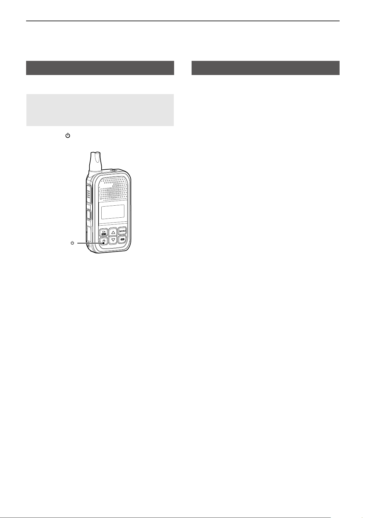
DOperating keys
[PTT] switch
Hold down to transmit, release to receive�
[ ] key
Hold down for 1 second to turn the transceiver ON or
OFF�
[PTT]
Microphone
[Side]*
[CH/SET]
[ ]
* Dealer assignable�
Function
display
[MONI]
]
[
[▲]/[▼]
[CH/SET] key
• On the Standby screen, push to enter or exit the
Channel Select mode�
• On the Standby screen, hold down for 1 second to
enter the Set mode�
• In the Set mode, push to move between the setting
items, and hold down for 1 second to return to the
Standby screen�
[▲]/[▼] key
• On the Standby screen, push to adjust the audio
level�
• In the Set mode and the Channel Select mode,
push to select a value�
[MONI] key
While holding down this key, the Monitor function is
ON in the Standby screen�
[ ] key
On the Standby screen, hold down for 1 second to
turn the Lock function ON or OFF�
DAbout the Software Key functions
The [Top] and [Side] key functions are dealer
assignable� See page 1-4 for details�
The following Software keys are assigned by default:
Key Assigned Software
[Top] Surveillance
[Side] High/Low
1-2
Page 5

1
PANEL DESCRIPTION
Right side panel
Speaker
microphone jack
USB connector
(Type-C) [USB]
DConnectors
SPEAKER MICROPHONE JACK
To connect an optional speaker microphone or
headset�
USB CONNECTOR (Type-C) [USB]
For only charging the battery�
L The USB connector does not support USB Power
Delivery (USB PD) or data communication�
CAUTION: DO NOT use the transceiver without
the connector covers or the optional equipment
attached�
The transceiver meets IP54 requirements for
dust-tight and splash resistance only when the
connector covers or the optional HM-183LS speaker
microphone is attached�
Function display
1 2 3
1 TX ICON
Displayed while transmitting�
2 ANTENNA ICON
• Displayed while the channel is busy (receiving)�
• Blinks while the monitor function is turned ON�
3 SIGNAL STRENGTH INDICATOR
Displays the relative receive signal strength level�
4 LOW POWER ICON
Displayed when low output power is selected�
4
5
7
6
8
9
6 VOX ICON
Displayed when the VOX function is ON�
7 KEY LOCK ICON
Displayed when the Key Lock function is ON�
8 BATTERY INDICATOR
• Blinks while charging�
• Displays the remaining battery charge�
Indication *
Battery
Status
Full Mid
Charging
required
Battery
exhausted
5 SCAN ICON
• Displayed when the channel is selected as a scan
target channel�
• Blinks while scanning�
* Blinks when the battery charge decreases to a set
level�
9 ALPHANUMERIC READOUT
Displays messages such as channel number�
1-3
Page 6

1
PANEL DESCRIPTION
Assignable Software Key functions
Null
No function�
High/Low
Push to toggle the transmit output power level�
Scan Start/Stop
• Push to start or cancel a scan�
• When the scan starts with the Power ON Scan
function, push to pause the scan� The paused scan
resumes after the period time entered in the Auto
Reset Timer has passed�
• Hold down this key while a scan pauses by
detecting a signal on a channel, and then the
channel is removed from the scan group�
The removed channel is automatically added to the
scan group after the scan is canceled�
Surveillance
Push to turn the Surveillance function ON or OFF�
When this function is turned ON, the beep does not
sound, and the backlight does not light, even when a
signal is received, or a key is pushed�
1-4
Page 7

Section 2
BASIC OPERATION
Turning ON the transceiver ��������������������������������������������������������������2-2
D Turning ON the transceiver ����������������������������������������������������������������������2-2
D Adjusting the audio level ��������������������������������������������������������������������������2-2
Selecting a channel ��������������������������������������������������������������������������2-2
D Selecting an operating channel ����������������������������������������������������������������2-2
Receiving and transmitting ���������������������������������������������������������������2-3
D Receiving �������������������������������������������������������������������������������������������������2-3
D Transmitting����������������������������������������������������������������������������������������������2-3
D Transmitting notes ������������������������������������������������������������������������������������2-3
2-1
Page 8
2
BASIC OPERATION
Turning ON the transceiver
DTurning ON the transceiver
NOTE: Before using the transceiver for the first time,
the battery pack must be fully charged for optimum
life and operation� See the BASIC MANUAL for
details�
z Hold down [
ON or OFF�
] for 1 second to turn the transceiver
[ ]
Selecting a channel
DSelecting an operating channel
1� On the Standby screen, push [CH/SET]�
• Enters the Channel Select mode, and the channel
number blinks�
2� Push [▲] or [▼] to select a channel, and then
push [CH/SET] to apply the setting�
• Returns to the Standby screen�
<Power ON Scan function>
Depending on the presetting, when the user turns ON
the transceiver, a scan automatically starts� The scan
stops when a call is received�
DAdjusting the audio level
z On the Standby screen, push [▲] or [▼] to adjust
the audio volume�
L The volume can be adjusted between 0 and 32�
2-2
Page 9

2
BASIC OPERATION
Receiving and transmitting
DReceiving
When a call is received, the antenna icon is displayed�
z Push [▲] or [▼] to adjust the audio output level to a
comfortable listening level�
DTransmitting
z While holding down [PTT], speak at your normal
voice level�
• The “ ” icon is displayed while [PTT] is held
down�
[PTT]
DTransmitting notes
Transmit inhibit function
The transceiver has several inhibit functions which
restrict transmission under the following conditions:
• The channel is busy� However, depending on the
presetting, you can transmit when a call is received
that includes a non-matching (or matching) CTCSS
(DTCS)�
• The selected channel is a ‘receive only’ channel�
Time-Out Timer
If continuous transmission exceeds the preset
Time-Out Timer time, the transmission is cut off�
Penalty timer
After the Time-Out Timer cuts off the transmission, the
transmission is further inhibited for a preset penalty
period of time�
IMPORTANT:
To maximize the readability of your signal:
1� After pushing [PTT], pause briefly before you
start speaking�
2� Hold the microphone 5 ~ 10 cm (2 ~ 4 inches)
from your mouth, then speak at your normal
voice level�
2-3
Page 10

Section 3
USER SET MODE
User Set mode description ���������������������������������������������������������������3-2
D Operation in the User Set mode ��������������������������������������������������������������3-2
User Set mode items ������������������������������������������������������������������������3-2
3-1
Page 11

3
USER SET MODE
User Set mode description
The user can enter the “User Set Mode” to customize
certain transceiver setting�
DOperation in the User Set mode
Example: Changing the Beep level 1 to 4�
1� Hold down [CH/SET] for 1 second to enter the Set
mode�
2� Push [CH/SET] to select an item�
(Example: Selecting Beep level (BV))
3� Push [▲] or [▼] to select an option.
(Example: Selecting Level 4)
4� Hold down [CH/SET] for 1 second to return to the
Standby screen�
User Set mode items
Item
Backlight
Beep
Beep Level
SQL Level
Mic Gain
VOX
VOX Gain
* Displayed when the optional headset is connected
with the OPC-2006LS
Backlight
Sets the Backlight status�
• OFF: Turns OFF the backlight�
• Auto: When pushing any key (except [PTT]), the
• ON: The backlight turns ON all the time�
Beep
Turns the key-touch beeps ON or OFF�
Beep Level
Sets the beep level�
• Range: 1 ~ 4
(Squelch Level)
(Microphone Gain)
plug adapter cable.
backlight automatically turns ON for 5 seconds�
Display
BL
BE
BV
SQ
MG
VX*
VG*
SQL Level
Sets the squelch level high or low�
Mic Gain
Sets the microphone sensitivity� Higher values make
the microphone more sensitive to the user’s voice�
• Range: 1 (low sensitivity) ~ 4 (high sensitivity)
VOX
Turns the VOX function ON or OFF�
When the VOX function is ON, receiving and
transmitting are automatically switched by detecting
sounds�
NOTE: To use the function, a headset and the
optional OPC-2006LS plug adapter cable are
required (purchase separately)�
VOX Gain
Sets the VOX gain�
Higher values make the VOX function more sensitive
to sounds�
• Range: 1 ~ 10
(Squelch Level)
(Microphone Gain)
3-2
Page 12

Section 4
OTHER FUNCTIONS
Channel Set mode operation ������������������������������������������������������������4-2
Reassigning a key function ��������������������������������������������������������������4-5
VOX function ������������������������������������������������������������������������������������4-6
D Optional unit connection ���������������������������������������������������������������������������4-6
D Turning the VOX function ON or OFF ������������������������������������������������������4-6
4-1
Page 13
4
OTHER FUNCTIONS
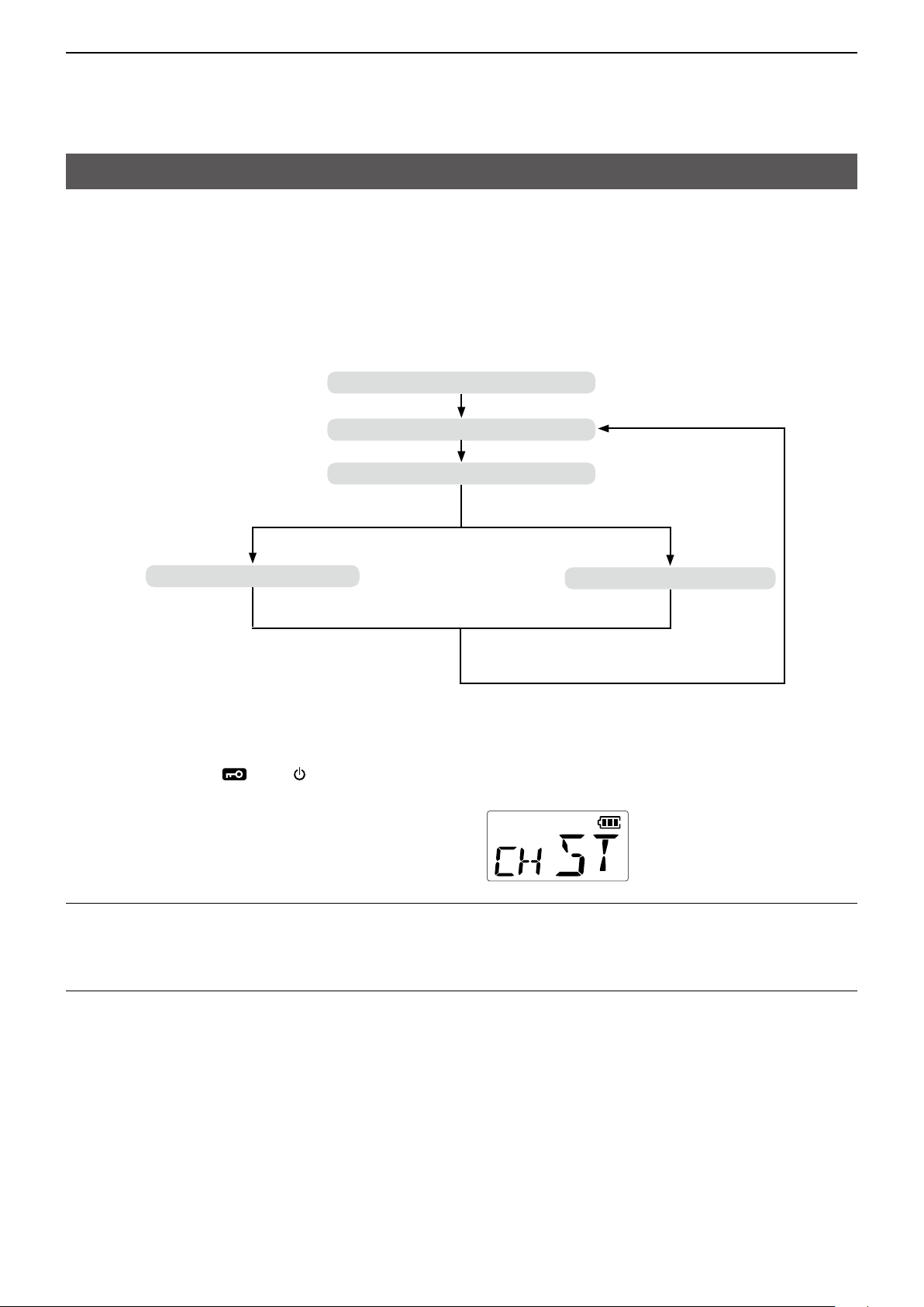
Channel Set mode operation
This function is convenient to rewrite CTCSS tone and DTCS code which are not assigned to the memory channel�
z Procedures
Turning ON the transceiver (p� 4-2)
Selecting a channel (p� 4-2)
Selecting a tone type (p� 4-2)
Setting a CTCSS tone (p� 4-3)
1� Turn OFF the transceiver�
2� Hold down [Side], [ ], and [ ] to turn ON the transceiver and enter the Channel Set mode�
• “CH ST,” and then channel number is displayed�
1. Selecting a channel
3� Push [▲] or [▼] to select a desired channel.
4� Push [CH/SET] to set the channel�
2. Selecting a tone type
5� Push [▲] or [▼] to select a desired tone type.
6� Push [CH/SET] to set the tone type�
Setting a DTCS code (p� 4-4)
When you select the CTCSS tone:
• The current CTCSS tone number is displayed�
➥Go to ʽ3. Setting a CTCSS toneʼ on the next page.
When you select the DTCS code:
• The current DTCS code number is displayed�
➥Go to ʽ4. Setting a DTCS codeʼ on page 4-4.
4-2
Page 14

4
OTHER FUNCTIONS
Channel Set mode operation
3. Setting a CTCSS tone
7� Push [▲] or [▼] to select the desired CTCSS tone number.
8� Push [CH/SET] to set the number�
• CTCSS tone number list
No. Freq. No. Freq. No. Freq. No. Freq. No. Freq.
01
67�0
02
69�3
03
71�9
04
74�4
05
77�0
06
79�7
07
82�5
08
85�4
09
88�5
10
91�5
Recommended CTCSS frequencies
67�0
69�3
71�9
74�4
77�0
When you want to change another channel setting:
➥Go to ʽ1. Selecting a channelʼ on page 4-2.
When you want to exit the Channel Set mode:
➥Go to ʽ5. Exiting the Channel Set modeʼ on the next page.
79�7
82�5
85�4
88�5
91�5
11
12
13
14
15
16
17
18
19
20
94�8
97�4
100�0
103�5
107�2
110�9
114�8
118�8
123�0
127�3
94�8
97�4
100�0
103�5
107�2
21
22
23
24
25
26
27
28
29
30
110�9
114�8
118�8
123�0
127�3
131�8
136�5
141�3
146�2
151�4
156�7
159�8
162�2
165�5
167�9
131�8
136�5
141�3
146�2
151�4
31
32
33
34
35
36
37
38
39
40
156�7
162�2
167�9
173�8
179�9
171�3
173�8
177�3
179�9
183�5
186�2
189�9
192�8
196�6
199�5
186�2
192�8
203�5
210�7
218�1
41
42
43
44
45
46
47
48
49
50
OF
(Hz)
203�5
206�5
210�7
218�1
225�7
229�1
233�6
241�8
250�3
254�1
OFF
(Hz)
225�7
233�6
241�8
250�3
4-3
Page 15

4
OTHER FUNCTIONS
Channel Set mode operation
4. Setting a DTCS code
9� Push [▲] or [▼] to select the desired DTCS code number.
10� Push [CH/SET] to set the number�
• DTCS code number list
No. Code No. Code No. Code No. Code No. Code
01/101
02/102
03/103
04/104
05/105
06/106
07/107
08/108
09/109
10/110
11/111
12/112
13/113
14/114
15/115
16/116
17/117
18/118
19/119
20/120
023
025
026
031
032
036
043
047
051
054
065
071
072
073
074
114
115
116
125
131
21/121
22/122
23/123
24/124
25/125
26/126
27/127
28/128
29/129
30/130
31/131
32/132
33/133
34/134
35/135
36/136
37/137
38/138
39/139
40/140
132
134
143
152
155
156
162
165
172
174
205
223
226
243
244
245
251
261
263
265
41/141
42/142
43/143
44/144
45/145
46/146
47/147
48/148
49/149
50/150
51/151
52/152
53/153
54/154
55/155
56/156
57/157
58/158
59/159
60/160
271
306
311
315
331
343
346
351
364
365
371
411
412
413
423
431
432
445
464
465
61/161
62/162
63/163
64/164
65/165
66/166
67/167
68/168
69/169
70/170
71/171
72/172
73/173
74/174
75/175
76/176
77/177
78/178
79/179
80/180
466
503
506
516
532
546
565
606
612
624
627
631
632
654
662
664
703
712
723
731
81/181
82/182
83/183
84/184
OF
732
734
743
754
OFF
L When you select No� 01-84, the code polarity is Normal�
When you select No� 101-184, the code polarity is Inverse�
Recommended DTCS codes
023
025
026
031
032
043
047
051
When you want to change another channel setting:
➥Go to ʽ1. Selecting a channelʼ on page 4-2.
When you want to exit the Channel Set mode:
➥Go to ʽ5. Exiting the Channel Set modeʼ below.
5. Exiting the Channel Set mode
11� Push [
TIP: You can check your current channel information by following the steps�
1� Turn OFF the transceiver�
2� Push [▲] and [ ] to enter Channel Information mode�
• Displays the current CTCSS tone number, the DTCS code number and frequency number�
054
065
071
072
073
074
114
115
] to turn OFF the transceiver, save the settings, and exit the Channel Set mode.
116
125
131
132
134
143
152
155
156
162
165
172
174
205
223
226
243
244
245
251
261
263
265
271
306
311
315
331
343
346
351
364
365
371
411
412
413
423
431
432
445
464
465
466
503
506
516
532
546
565
606
612
624
627
631
632
654
662
664
703
712
723
731
732
734
743
754
4-4
Page 16

4
OTHER FUNCTIONS
Reassigning a key function
You can reassign another function to the [Side] and [Top] programmable function keys�
1� Turn OFF the transceiver�
2� Hold down [ ], [Top], and [ ] to enter the Key
Assignment mode�
• “KY ST” is displayed�
3� Push [Side] or [Top] to select the key that you
want to reassign�
4� Push [▲] or [▼] to select a desired key function.
• Options
1: Null
2: Scan Start/Stop
3: Surveillance
4: High/Low
5� Push [ ] to turn OFF the transceiver to exit the
Key Assignment mode�
When the surveillance
function is assigned to
[Side]
When the scan function
is assigned to [Top]
4-5
Page 17

4
OTHER FUNCTIONS
VOX function
The VOX function toggles the transceiver between transmit and receive by your voice� This function provides
hands-free operation�
To use the VOX function, the optional OPC-2006LS plug adapter cable and an optional headset (HS-94, HS-95,
or HS-97) are required�
DOptional unit connection
1� Turn OFF the transceiver�
2� Connect an optional headset and OPC-2006LS as
shown to the right�
OPC-2006LS
Turn OFF
* You can also use this function with the optional HS-95 or
HS-97�
DTurning the VOX function ON or OFF
You can turn the VOX function ON or OFF in the Set mode�
See page 3-2 for details�
L When the VOX function is ON, is displayed on the Standby screen�
To the
speaker
microphone
jack
HS-94*
4-6
Page 18

Section 5
OPTIONS
Battery charging �������������������������������������������������������������������������������5-2
D Battery charging ��������������������������������������������������������������������������������������� 5-2
D Charging directly ��������������������������������������������������������������������������������������5-2
D Charging on the cradle ����������������������������������������������������������������������������� 5-2
D Rapid charging the battery pack ��������������������������������������������������������������5-3
5-1
Page 19

5
ac adapter
OPTIONS
Battery charging
DBattery charging
• Fully charge the transceiver before using it for the first time, or if it has not been used for more than 2 months�
The charger automatically restarts charging when the battery voltage drops�
• Disconnect the AC adapter from the outlet when not charging the battery�
• Use the supplied AC adapter�
• The battery icon on the function display blinks while charging and lights when the charging has been completed�
DCharging directly
To the [USB] connector
Turn OFF
To an AC outlet
AC adapter
DCharging on the cradle
Turn OFF
Charging cradle
(BC-262)
NOTE: Be sure the
tabs on the transceiver
are correctly aligned
with the guide rails
inside the cradle�
Tabs
Guide rails
AC adapter
USB Type-C
Charging time with the BC-263A
NOTE: If “Q ER” is displayed, a charging error has occurred�
• Disconnect the AC adapter, and then connect properly�
• Properly install the battery pack to the transceiver�
• Properly insert the transceiver into the charging cradle�
• Charge the battery pack within the specified temperature range: 15°C ~ 40°C (59°F ~ 104°F)�
is approximately 5�5 hours�
5-2
L Charging together
with one cable is not
supported� Charge by
inserting a cable into
each charger�
Page 20

5
OPTIONS
Battery charging
DRapid charging the battery pack
You can charge the battery pack with the optional BC-264 battery charger�
Install the supplied battery pack so that the terminals of the battery pack and the battery charger meet�
Charging time with the BC-263A ac adapter is approximately 5�5 hours�
NOTE: Charging time will be longer in extremely hot or cold environments�
We recommend charging between 15°C ~ 40°C (59°F ~ 104°F)�
L The battery pack can be charged by the charging with
AC adapter
BC-262 inserted�
USB Type-C
Battery pack
BC-264
Charging indicator
• Lights orange: Charging
• Not lit: Battery not installed or
charging completed
BC-264
Charging
indicator
Battery pack
Charging cradle
(BC-262)
TIP: To remove the battery pack, slide the battery pack and lift it up in the direction of the arrow�
USB
Type-C
AC adapter
5-3
Page 21

How the World Communicates
A7725-11US
© 2023 Icom Inc. Jun. 2023
1-1-32 Kamiminami, Hirano-ku, Osaka 547-0003, Japan
 Loading...