

Page 1

INSTRUCTION MANUAL
144 MHz FM TRANSCEIVER
iT2H
This device complies with Part 15 of the FCC rules. Operation is subject to the following two conditions: (1) This device may not cause
harmful interference, and (2) this device must accept any interference
received, including interference that may cause undesired operation.
Page 2

IMPORTANT
CAUTIONS
READ ALL INSTRUCTIONS carefully and com-
pletely before using the transceiver.
SAVE THIS INSTRUCTION MANUAL—This in-
struction manual contains important operating instructions for
the IC-T2H.
RWARNING! NEVER hold the transceiver so that the
antenna is very close to, or touching exposed parts of the
body, especially the face or eyes, while transmitting. The
transceiver will perform best if the microphone is 5 to 10 cm
(2 to 4 in) away from the lips and the transceiver is vertical.
RWARNING! NEVER operate the transceiver with a
headset or other audio accessories at high volume levels.
EXPLICIT DEFINITIONS
The explicit definitions below apply to this instruction manual.
WORD DEFINITION
RWARNING
CAUTION
NOTE
Personal injury, fire hazard or electric
shock may occur.
Equipment damage may occur.
If disregarded, inconvenience only. No risk
of personal injury, fire or electric shock.
Hearing experts advise against continuous high volume operation. If you experience a ringing in your ears, reduce the
volume or discontinue use.
NEVER connect the transceiver to an AC outlet or to a
power source of more than 16 V DC. Such a connection will
damage the transceiver.
NEVER connect the transceiver to a power source that is
DC fused at more than 5 A. Accidental reverse connection will
be protected by this fuse, higher fuse values will not give any
protection against such accidents and the transceiver will be
ruined.
NEVER attempt to charge alkaline or dry cell batteries. Be-
ware that external DC power connections will charge batteries
inside the battery case. This will damage not only the battery
case but also the transceiver.
ii
Page 3
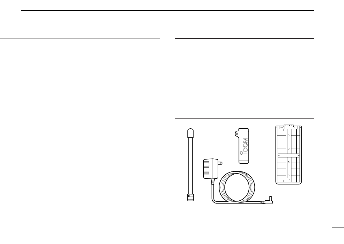
SUPPLIED ACCESSORIES
➀
➂
➁
➃
DO NOT push the PTT when not actually desiring to trans-
mit.
Place unit in a secure place to avoid inadvertent use by children.
DO NOT operate the transceiver near unshielded electri-
cal blasting caps or in an explosive atmosphere.
AVOID using or placing the transceiver in direct sunlight or
in areas with temperatures below –10°C (+14°F) or above
+60°C (+140°F).
The use of non-Icom battery packs/chargers may impair
transceiver performance and invalidate the warranty.
Even when the transceiver power is OFF, a slight current still
flows in the circuits. Remove the battery pack or case from
the transceiver when not using it for a long time. Otherwise,
the battery pack or installed Ni-Cd batteries will become exhausted.
For USA only:
Caution: Changes or modifications to this transceiver, not expressly approved by Icom Inc., could void your authority to
operate this transceiver under FCC regulations.
Accessories included with the transceiver:
➀ Antenna . . . . . . . . . . . . . . . . . . . . . . . . . . . . . . . . . . . . . 1
➁ Belt clip . . . . . . . . . . . . . . . . . . . . . . . . . . . . . . . . . . . . . 1
➂ Battery case (BP-194)
with 8 Ni-Cd (AA) batteries* installed . . . . . . . . . . . . . . . 1
➃ Wall charger* . . . . . . . . . . . . . . . . . . . . . . . . . . . . . . . . . 1
*Not supplied with some versions.
iii
Page 4

TABLE OF CONTENTS
IMPORTANT ................................................................................................... ii
EXPLICIT DEFINITIONS ................................................................................ ii
CAUTIONS ..................................................................................................... ii
SUPPLIED ACCESSORIES ........................................................................... iii
TABLE OF CONTENTS ................................................................................. iv
1 ACCESSORY ATTACHMENT ................................................................... 1
2 PANEL DESCRIPTION ......................................................................... 2–7
■ Switches, controls, keys and connectors ............................................... 2
■ Customizable keys ................................................................................. 5
■ Custom key assignment ........................................................................ 5
■ Function display ..................................................................................... 6
3 BATTERY PACKS ............................................................................... 8–10
■ Battery pack charging ............................................................................ 8
■ Charging precautions ............................................................................. 8
■ About battery packs ............................................................................... 8
■ Charging connections ............................................................................ 9
■ Installing batteries in the battery case ................................................. 10
4 BASIC OPERATION ..........................................................................11–14
■ Power ON ............................................................................................. 11
■ Setting a frequency .............................................................................. 11
■ Dial select function ............................................................................... 12
■ Receive and transmit ........................................................................... 12
■ Selecting a memory channel ............................................................... 13
■ Lock function ........................................................................................ 13
■ Notes for set mode .............................................................................. 14
■ Setting tuning steps ............................................................................. 14
5 REPEATER OPERATION ................................................................. 15–18
■ General ................................................................................................ 15
■ Subaudible tones ................................................................................. 16
■ Offset frequency ................................................................................... 16
■ Auto repeater function ......................................................................... 17
6 MEMORY/CALL PROGRAMMING ................................................... 19–21
■ General ................................................................................................ 19
■ Programming a memory channel ......................................................... 19
■ Programming the call channel ............................................................. 20
■ Memory editing .................................................................................... 21
7 DTMF MEMORY ............................................................................... 22–23
■ Programming a DTMF code ................................................................ 22
■ Transmitting a DTMF code .................................................................. 22
■ DTMF transmission speed ................................................................... 23
8 SCAN OPERATION .......................................................................... 24–25
■ Scan types ........................................................................................... 24
■ Programmed scan ............................................................................... 25
■ Memory (skip) scan ............................................................................. 25
9 SUBAUDIBLE TONE OPERATION .................................................. 26–27
■ Tone squelch ........................................................................................ 26
■ Tone scan ............................................................................................ 27
■ Pocket beep operation ......................................................................... 27
10 OTHER FUNCTIONS ........................................................................ 28–32
■ Initial set mode ..................................................................................... 28
■ Resetting the CPU ............................................................................... 30
■ Key customize mode ........................................................................... 31
■ Guide function ...................................................................................... 31
11 ANI OPERATION .............................................................................. 33–35
■ ANI mode ON ...................................................................................... 33
■ General ................................................................................................ 33
■ Operation ............................................................................................. 34
12 CLONING ................................................................................................ 36
13 TROUBLESHOOTING ............................................................................ 37
14 SPECIFICATIONS ................................................................................... 38
15 OPTIONS ................................................................................................ 39
16 MODE ARRANGEMENT .................................................................. 40–41
17 CE ...................................................................................................... 42–43
iv
Page 5
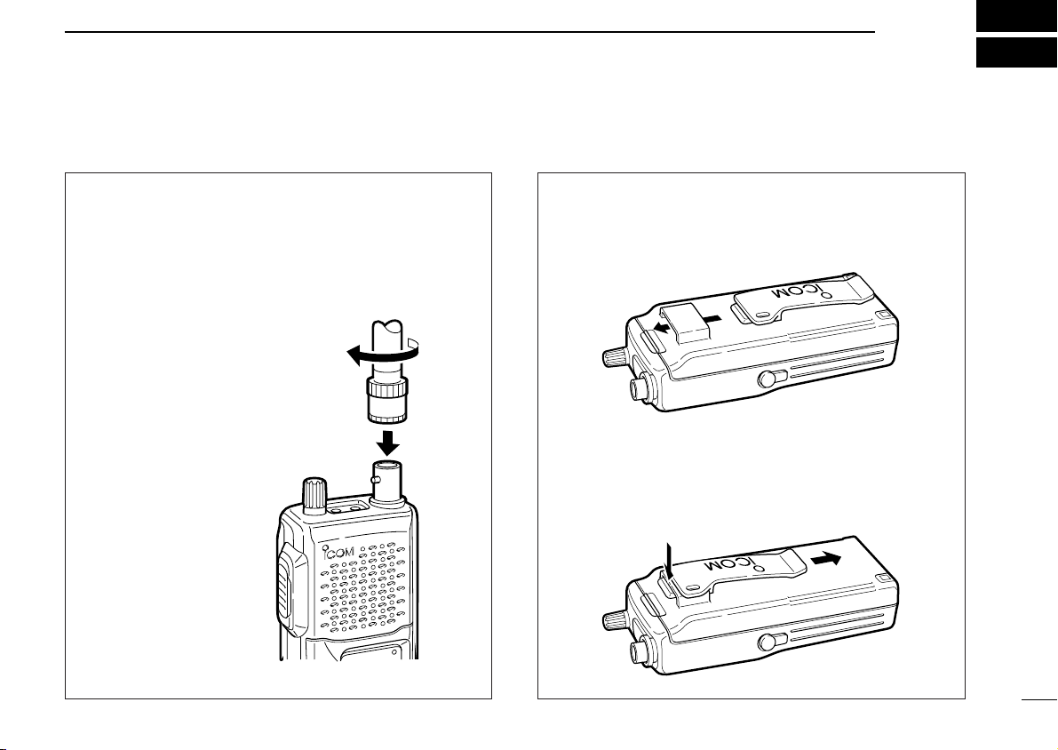
ACCESSORY ATTACHMENT
1
D Antenna
Connect the supplied flexible antenna to the antenna connector and rotate the antenna clockwise.
u CAUTION: Transmitting without an antenna may
damage the transceiver.
D Belt clip
To attach:
Slide the belt clip into the plastic loop on the back of the
battery case/pack.
To remove:
Push the top of the belt clip towards the transceiver and at
the same time, push it downwards and free of the plastic
loop.
1
Page 6
2
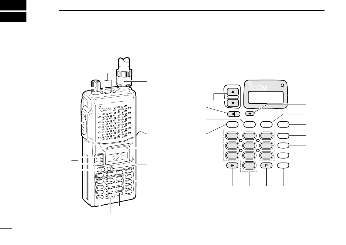
PANEL DESCRIPTION
■ Switches, controls, keys and connectors
[SP/MIC]
e
[PWR/VOL]
w
r[ANTENNA]
y
u
i
o
!2
[PTT]
q
[UP/DOWN]
u
[MONITOR]
i
t[CHARGE]
y[TX]
o[DIAL SELECT]
!1
!0
SQL
SC
DUP
12
4
79
3
6
5
8
0
H/L
A V
B M
C T
D L
!3
!4
!5
!6
!0-!7
[CUSTOMIZABLE
@0 !9
!8
!7
KEYS]
[GUIDE]
!8
[DIGIT KEYS]
!9
[MHz KEY]
@0
2
Page 7
PANEL DESCRIPTION
This connection
does not apply
when a condensor microphone
is connected.
Remote Audio out
(8 Ω)
[SP]
MIC
5 V
PTT
[MIC]
Audio input
PTT
33 kΩ
(2 kΩ)
2
q PTT SWITCH [PTT] (p. 12)
Push and hold to transmit; release to receive.
w POWER/VOLUME CONTROL [PWR/VOL]
➥ Rotate to turn power on and off.
➥ Rotate clockwise to increase volume and counterclock-
wise to decrease volume.
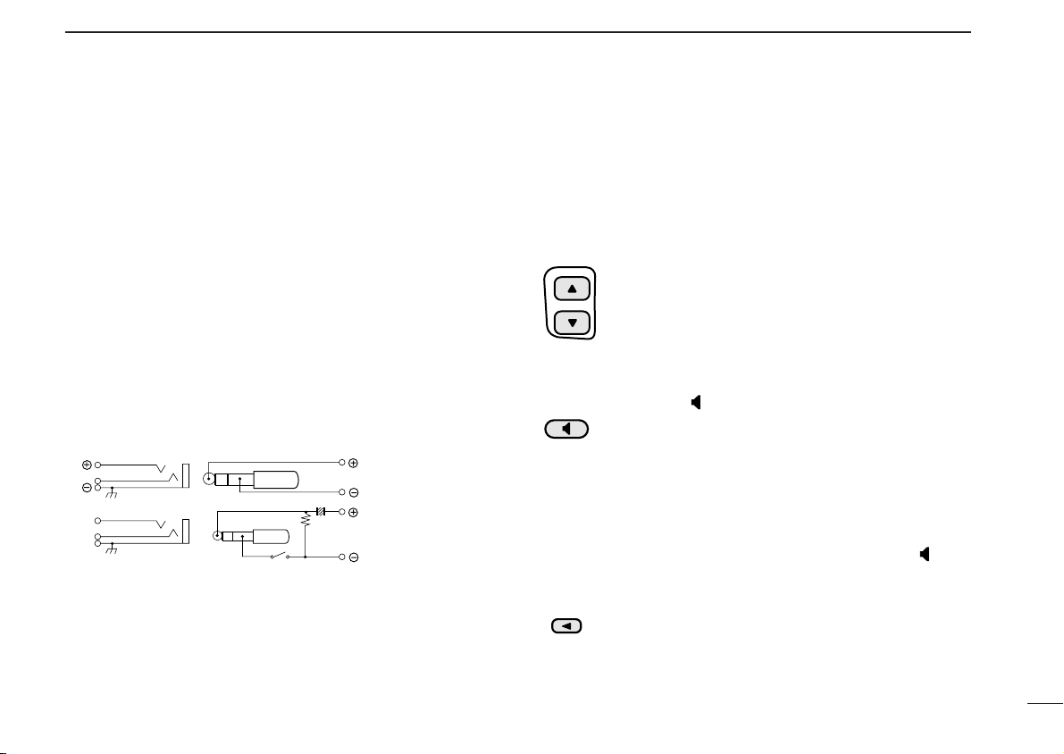
e EXTERNAL SPEAKER AND MICROPHONE JACKS
[SP/MIC]
Connect an optional speaker-microphone or headset, if desired. The internal microphone and speaker will not function when either is connected. (See p. 37 for options.)
D External connection
☞
NOTE: When connecting or disconnecting an external
speaker-microphone, first turn off power to the transceiver.
r ANTENNA CONNECTOR (p. 1)
Connects the supplied antenna.
t EXTERNAL DC POWER JACK [CHARGE]
Connect a 13.5 to 16 V DC power source using optional
cables, CP-12L or OPC-254L, to charge the batteries, or
connect the BC-110A/D/V wall charger for charging.
u CAUTION: This connection is for charging only. Power
to the transceiver must be turned off during charging.
y TX INDICATOR [TX] (p. 12)
Lights red while transmitting.
u UP/DOWN KEY [Y]/[Z]
➥ In VFO mode, increment or decrement the dis-
played frequency according to the set tuning
steps. (p. 11)
➥ In memory mode, increment or decrement the
selected memory channel. (p. 13)
➥ In initial set mode, select item conditions. (p. 28)
i MONITOR KEY [ (MONI)] (p. 13)
➥ Push and hold this switch to force the squelch
open; release to close it again.
➥ Push twice to keep the squelch open; push
again to close it.
➥ While pushing [PTT], push this switch to trans-
mit a 1750 Hz tone signal. (Europe version only)
➥ When a digit is mistakenly input, push [ ] and
input from the beginning.
o DIAL SELECT KEY [t] (p. 12)
Push this switch one or more times to select the
dial select step for frequency tuning.
3
Page 8

1
D L
C T
B M
A V
H/L
DUP
SC
SQL
0
2
PANEL DESCRIPTION
!0 SQUELCH KEY [SQL]*
➥ Push [SQL], then push [Y]/[Z] one or more
times to select squelch level. “AUto”, “Sql 1” to
“Sql 8” are available to suit personal preferences
and operating conditions. (p. 13)
!1 SCAN START/STOP KEY [SC]*
➥ Push [SC] to start the scan. (p. 25)
• To change the scan direction, push [Y] or [Z].
➥ Push [SC] again to stop the scan. (p. 25)
!2 DUPLEX KEY [DUP]*
➥ Push once to select – DUP or twice to select
DUP mode. (p. 15)
!3 POWER SELECT KEY [H/L]*
➥ Push to toggle high and low power output. (p.
12)
•“LOW” appears when low power is selected.
!4 VFO/MEMORY KEY [A V]*
➥ Push to toggle VFO mode and memory mode.
(p. 11)
•“X” appears when memory mode is selected.
➥ Push for 1 sec. to enter “Set mode”. (p. 14)
➥ Transmits an “A” for DTMF operation while
pushing [PTT].
!5 MEMORY WRITE KEY [
➥ Push [
B M], then select a memory channel num-
B M]*
ber with [Y]/[Z].
➥ Push [
➥ Transmits a “B” for DTMF operation while push-
!6 TONE SETTING KEY [
➥ Toggles tone squelch operation ON/OFF.
➥ Transmits a “C” for DTMF operation while push-
!7 LOCK KEY [
➥ Toggles the lock function ON/OFF. (p 13)
➥ Transmits a “D” for DTMF operation while push-
!8 GUIDE KEY [#] (p. 31)
➥ Activates the guide function.
➥ Transmits an “F” for DTMF operation while
!9 DIGIT KEYS
➥ Input the specified digit during frequency input,
to
➥ Transmit the DTMF code of the specified digit
@0 MHz KEY [M] (p. 12)
➥ Used as a short cut for inputting frequencies.
➥ Transmits an “E” for DTMF operation while
B M] for 1 sec. to program the information
into the memory channel. (p. 19)
ing [PTT].
C T]*
•“T”, “TSQL” or “TSQL” appears on the display.
ing [PTT].
D L]*
ing [PTT].
pushing [PTT].
memory channel selection, etc.
while pushing [PTT].
pushing [PTT].
4
Page 9

PANEL DESCRIPTION
2
■ *Customizable keys
[SQL], [SC], [DUP], [H/L], [A V], [B M], [
These keys can be assigned a variety of functions (see p. 32
for a list of available functions).
NOTE: In this manual, the customized keys are represented
by the “
” icon. Operations which require a customizable key
f
observe the following style—
Push [
where “
(FUNCTION)]
f
” indicates the key is customized and “FUNCTION”
f
indicates the assigned function e.g. TONE, etc.
D Guide function (p. 31)
The guide function displays the function of keys and switches
quickly and easily.
Once a key function has been changed from its default, the
guide function is a convenient way to determine its function.
C T], [D L]
■ Custom key assignment
Key Default
[Y]UP fixed
[Y] DOWN fixed
[t] MONI fixed
[ ] DIAL SELECT fixed
[SQL] SQUELCH
[SC] SCAN
[DUP] DUPLEX
[H/L] HI/LO
[0]–[9] NUMERAL INPUT fixed
[
A V] V/m
B M] SmW
[
[
C T] TONE
[
D L] LOCK
[#] MHz KEY fixed
[
] GUIDE KEY fixed
M
Write down your key assignments for reference.
Your
Assignment
5
Page 10
2
MR
DUP
SKIP
LOW
T SQL
PANEL DESCRIPTION
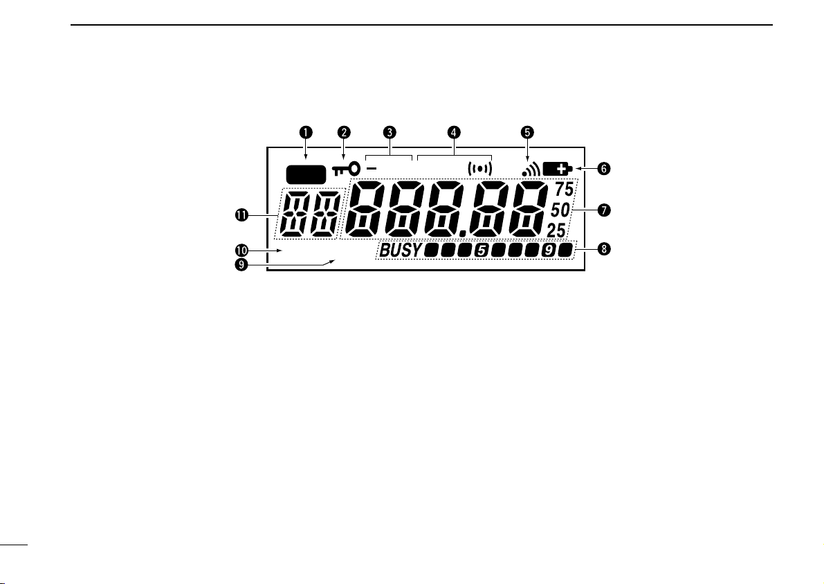
■ Function display
q MEMORY MODE INDICATOR (p. 13)
Appears while in memory mode.
w LOCK INDICATOR (p. 13)
Appears while the lock function is activated.
e DUPLEX INDICATOR (p. 15)
Appears during semi-duplex operation.
•“–DUP” appears for minus duplex; “DUP” appears for plus du-
plex.
r TONE INDICATORS
“T” appears when the subaudible tone encoder (p. 16) is in
use; “T SQLS” appears during pocket beep operation
(p. 27) and “T SQL” appears when the tone squelch function (p. 26) is activated.
6
t ANI INDICATOR (p. 33)
Appears when the transceiver is set to ANI (Automatic
Number Identification) operation mode.
y LOW BATTERY INDICATOR
➥ Appears when the battery is nearing exhaustion.
➥ Appears and flashes when battery replacement is nec-
essary.
u FREQUENCY READOUT
➥ In frequency indication mode, indicates the operating
frequency. (p. 11)
• The smaller “75,” “50” and “25” to the right of the readout in-
dicates 7.5, 5.0 and 2.5 kHz, respectively.
➥ In channel indication mode, indicates the selected chan-
nel. (p. 11)
Page 11

➥ In set mode or initial set mode, indicates the selected
item, condition, etc.
i BUSY AND S/RF INDICATORS (p. 12)
➥ “BUSY” appears when receiving a signal or when the
squelch is open.
➥ The S/RF indicators show the relative signal strength
while receiving and the output power when transmitting
(2 segments appear for low power and all segments appear for high power).
o LOW POWER INDICATOR (p. 12)
Appears when low output power is set.
!0 SKIP INDICATOR (p. 25)
Appears when the selected channel is set as a “skip” channel.
!1 MEMORY CHANNEL INDICATOR (p. 13)
Indicates the selected memory channel and other items
such as the call channel.
PANEL DESCRIPTION
2
7
Page 12

3
RBRC
RBRC
Ni-
Cd
BATTERY PACKS
■ Battery pack charging
The supplied BP-194
Ni-Cd batteries* and can be charged approx. 300 times.
Charge the batteries before first operating the transceiver or
when they become exhausted.
If you want to be able to charge the batteries more than 300
times, the following points should be observed:
1. Avoid overcharging. The charging period should be less
than 48 hours.
2. Use the batteries until they become completely exhausted
under normal conditions. We recommend battery charging
just after transmitting becomes impossible.
*Not supplied with some versions.
BATTERY CASE
includes rechargeable
■ About battery packs
D Operating period
Depending on installed battery pack (batteries), the operating
period of the transceiver varies. Refer to p. 39 for operating
period details.
D Battery life
If your batteries seem to have no capacity even after being
fully charged, completely discharge them by leaving the
power ON overnight. Then fully charge them again.
If the batteries still do not retain a charge (or very little), new
batteries must be purchased.
■ Charging precautions
NEVER attempt to charge dry cell/alkaline batteries. This will
cause internal liquid leakage and damage the battery case
and transceiver.
NEVER connect two or more chargers at the same time.
Charging may not occur under temperatures of 10°C (50°F)
or over temperatures of 40°C (104°F).
8
Recycling information (USA only)
The product that you purchased contains a
rechargeable battery. The battery is recyclable. At
the end of its useful life, under various state and
local laws, it may be illegal to dispose of this battery into the
municipal waste stream. Call 1-800-8-BATTERY for battery
recycling options in your area or contact your dealer.
Page 13
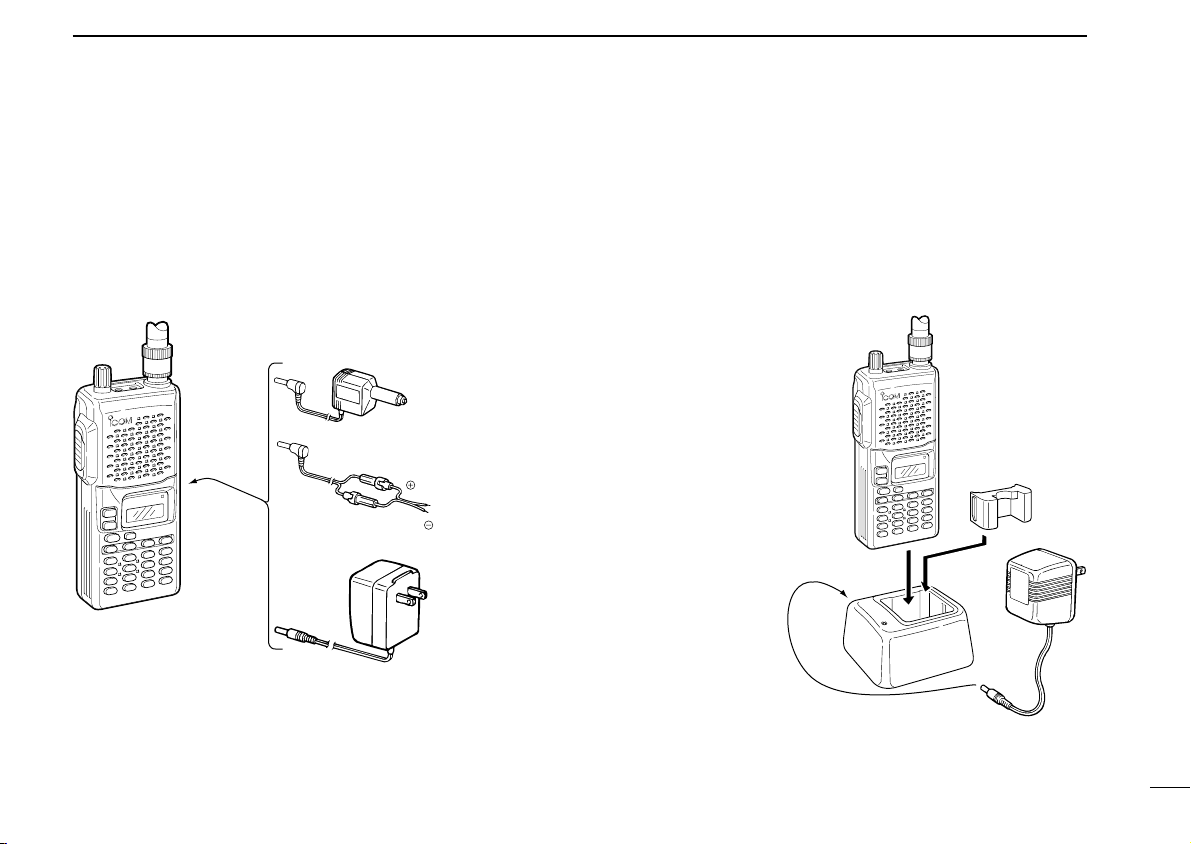
■ Charging connections
Transceiver with
attached
battery case
(pack)
BC-110A/D/V*
CP-12L
(optional)
OPC-254L
(optional)
To a 13.5
to 16 V DC
power source
To
[CHARGE]
white
black
BATTERY PACKS
3
D Regular charging
When charging a battery case (pack) attached to the transceiver the power must be OFF.
Charging periods:
15 hours (w/BP-195)
20 hours (w/BP-196)
*Not supplied with some versions.
D Rapid charging with the BC-119
The optional BC-119 provides rapid charging of optional
Ni-Cd battery packs (power to the transceiver must be OFF
during charging). The following are additionally required:
• AD-81
• An AC adapter (may be supplied
with the BC-119 depending
on version).
Charging periods:
1 hour (w/BP-195)
1.5 hours (w/BP-196)
9
Page 14
3
BATTERY PACKS
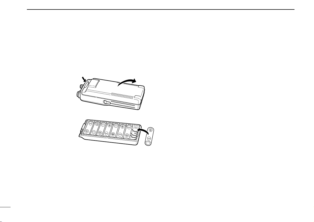
■ Installing batteries in the
battery case
When using a battery case attached to the transceiver, install
8 AA(R6) size Ni-Cd or alkaline batteries as illustrated below.
➀ Remove the bat-
tery case from the
transceiver.
➁ Install 8 × R6(AA)
size Ni-Cd or alkaline batteries.
• Be sure to observe
the correct polarity.
● NEVER connect DC power to the transceiver when in-
stalling dry cell or alkaline batteries. Such a connection will
damage the transceiver.
● Be careful of battery overcharging. When operating via ex-
ternal DC power, installed batteries are simultaneously
charged.
● Keep battery contacts clean. It’s a good idea to clean bat-
tery terminals once a week.
10
Page 15
BASIC OPERATION
Frequency indication Channel indication
at power ON
0
MR
MR
0 0
5
54
1
4
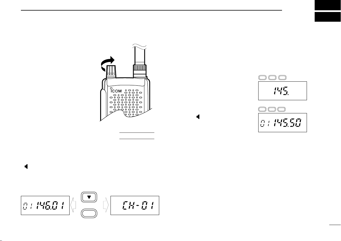
■ Power ON
Rotate [PWR/VOL] clockwise
to turn power ON.
D Toggling frequency/channel
indication mode
Channel indication mode is used to simplify operation. In this
mode only pre-programmed memory channel numbers are
displayed and functions are limited ([PWR/VOL], [
[ ], [H/L] and [SC] are functional).
To toggle between the indication modes:
While pushing [Z] + [0], rotate [PWR/VOL] to turn power ON.
AT
POWER ON
D L], [PTT],
■ Setting a frequency
D Via the keypad
➀ Push [A V] to select VFO mode, if
necessary.
➁ Push 6 digit keys, starting from
the 100 MHz digit, to input a frequency.
• Push the [M] key first to start input
from the 100 kHz digit, if desired.
• When a digit is mistakenly input,
push [ ] and input from the begin-
ning.
•“2” and “7” are acceptable for the 1
kHz digits (depending on the 10 kHz digit).
D Using the [Y]/[Z] keys
Each push increments/decrements the frequency according
to the selected tuning step (see right), except when the 100
kHz or 1 MHz dial select step is selected (see following
page). When a dial select step is selected, each push increments/decrements the frequency either 100 kHz or 1 MHz.
11
Page 16

4
1 MHz tuning selected
100 kHz tuning selected
Regular tuning selected
BASIC OPERATION
■ Dial select function
Use the dial select function to adjust the tuning behaviour or
the [Y]/[Z] keys—use 1 MHz tuning when you want to
change the frequency in large increments; use the selected
tuning step when you want to change the frequency in smaller
increments.
➀ Push [t] one or more times to
select the desired [Y]/[Z] key
tuning increment.
• 1 MHz tuning, 100 kHz tuning or
regular tuning steps can be selected
(see diagram at right).
➁ Release [t] to return to normal operation.
■ Receive and transmit
➀ Rotate [PWR/VOL] clockwise to turn power ON.
➁ Adjust volume to the desired level.
• While pushing [ ], rotate [VOL].
➂ Set a frequency.
When a signal is received:
➥ Squelch opens and audio is emitted from the speaker.
➥ “BUSY” appears and the S/RF indicator shows the relative sig-
nal strength.
➃ Push [H/L] to toggle output power between high and low.
•“LOW” appears when low output power is selected.
➄ Push and hold [PTT] to transmit; then speak into the mi-
crophone.
• Do not hold the microphone too close to your mouth or speak
too loudly. This may distort the signal.
• The TX indicator lights red.
• The S/RF indicator shows the output power selection.
12
Page 17

BASIC OPERATION
MR
MR
P0
0
4
4
✔ Convenient
Monitor function: Push and hold [ ] to listen to weak sig-
nals that do not open the squelch; or push [ ] twice to monitor a signal without having to continuously hold [ ].
Squelch control: The transceiver employs a noise pulse
count system and therefore, squelch is adjusted automatically
when “AUto” is selected for the squelch level:
Push [SQL], then push [Y]/[Z] one or more times until “AUto”
appears. Manual levels from “Sql 1” to “Sql 8” are also available to suit personal preferences and operating conditions.
■ Selecting a memory channel
➀ Push [A V] to select memory chan-
nel mode, if necessary.
•“X” appears.
➁ Push 2 digit keys to select the de-
sired memory channel (or push the
[Y]/[Z] keys).
• The first nine memory channels are
preceded by a “0.”
• When you want to select scan edge
channels PA or Pb, push [4], [1] or [4],
[2], respectively.
■ Lock function
The lock function prevents accidental frequency changes and
accidental function activation. By default, [
function on and off.
Push [
D L] for 1 sec. to toggle the function on and off.
•“é” appears while the lock func-
tion is activated.
• [PTT], [PWR/VOL] and [ ]can be
used regardless of this setting.
D L] toggles this
13
Page 18

4
This display shows that a tuning step of 25
kHz is selected.
BASIC OPERATION
■ Notes for “Set mode”
■ Setting tuning
USING
SET MODE
14
The following items can be set from VFO mode.
Set mode items:
Tuning steps (p. 14)
Duplex setting (p. 15)
Repeater tones (p. 16)
Offset frequency (p. 16)
Subaudible tones (p. 16)
Call channel (p. 20)
CTCSS tones (p. 26)
When setting items from memory mode, input data will disappear when changing memories or turning power OFF.
Please select VFO mode before entering set mode, and read
the instructions for each set mode item carefully.
To turn set mode ON and OFF:
➀ Push [A V] or [
➁ Push [t] one or more times to select the item.
➂ Push the [Y/Z] keys to select the desired value.
➃ Push [A V] or [
(CALL)]* for 1 sec. to enter set mode.
f
(CALL)]* to exit set mode.
f
steps
The transceiver has 8 tuning steps as follows:
5 kHz 10 kHz 12.5 kHz 15 kHz
20 kHz 25 kHz 30 kHz 50 kHz
➀ Push [A V] or [
➁ Push [t] one or more times to select the tuning step item.
➂ Push the [Y/Z] keys to select the desired tuning step.
➃ Push the same key used in step ➀ above to enter the tun-
ing step and exit set mode.
For convenience, select a tuning step that matches the frequency intervals of repeaters in your area.
*☞NOTE:
Selecting a tuning step is possible using one of the programmable key/switches when this function is assigned
using key customize mode (p. 31). In this case, pushing
[
(tS)] enters tuning step mode.
f
When pushing [ ] to exit set mode, any changes made
while in set mode are cancelled.
(CALL)]* for 1 sec. to enter set mode.
f
Page 19

REPEATER OPERATION
5
■ General
When using a repeater, the transmit frequency is shifted from
the receive frequency by the offset frequency. It is convenient
to program repeater information into memory channels (p.
19).
➀ Set the receive frequency (repeater output frequency).
➁ Push [DUP] one or more times to select –DUP or DUP.
•“–DUP” indicates the transmit frequency is shifted down; “DUP”
indicates the transmit frequency is shifted up.
• When the auto repeater function is in use (USA version only) this
selection and step ➂ are not necessary (p. 17).
➂ Push [C T] to activate the subaudible tone encoder, ac-
cording to repeater requirements.
•“T” appears.
• Refer to the table of subaudible tone frequencies on the following
page.
➃ Push and hold [PTT] to transmit.
• The displayed frequency automatically changes to the transmit
frequency (repeater input frequency).
• If “oFF” appears, check the offset frequency (p. 16).
➄ Release [PTT] to receive.
➅ Push and hold [ ] to check whether the other station’s
transmit signal can be directly received or not.
D Tone information
Some repeaters require a tone to be accessed. In this case,
precede step ➃ at left with the required tone.
DTMF TONES
While pushing [PTT], push the desired digit key(s) to transmit
DTMF tones.
• The transceiver has 5 DTMF memory channels. See p. 22 for de-
tails.
1750 Hz TONE (European version only)
While pushing [PTT], push and hold [ ] for 1 to 2 sec. to
transmit a 1750 Hz tone signal.
✔ Convenient
Tone scan function: When you don’t know the subaudible
tone used for a repeater, the tone scan is convenient for detecting the tone frequency.
Push and hold [SC] to activate the tone scan. See p. 27 for
more details.
15
Page 20

5
T
Subaudible tone of
88.5 Hz is selected.
Offset frequency of
0.60 MHz is selected.
DUP
REPEATER OPERATION
USING
■ Subaudible tones
Some repeaters require subaudible tones to be accessed.
Subaudible tones are superimposed over your normal signal
and must be set in advance.
SET MODE
➀ Push [A V] for 1 sec. to enter set mode.
➁ Push [t] one or more times until
“RP” appears.
➂ Push [Y]/[Z] to select the desired
subaudible tone.
➃ Push [A V] to enter the selected
tone and exit set mode.
When set mode is selected from memory mode:
➄ Push [B M].
➅ Push [A V].
➆ Push [B M] for 1 sec.
Available subaudible tone frequencies (unit: Hz)
67.0 79.7 94.8 110.9 131.8 156.7 171.3 186.2 203.5 229.1
69.3 82.5 97.4 114.8 136.5 159.8 173.8 189.9 206.5 233.6
71.9 85.4 100.0 118.8 141.3 162.2 177.3 192.8 210.7 241.8
74.4 88.5 103.5 123.0 146.2 165.5 179.9 196.6 218.1 250.3
77.0 91.5 107.2 127.3 151.4 167.9 183.5 199.5 225.7 254.1
USING
■ Offset frequency
When communicating through a repeater, the transmit frequency is shifted from the receive frequency by an amount
determined by the offset frequency.
SET MODE
➀ Push [A V] for 1 sec. to enter set mode.
➁ Push [t] one or more times until
“oW” appears.
➂ Push [Y]/[Z] to select the desired
offset frequency.
• Selectable steps are the same as the
pre-set tuning steps.
➃ Push [A V] to enter the selected offset frequency and exit
set mode.
When set mode is selected from memory mode:
➄ Push [B M].
➅ Push [A V].
➆ Push [B M] for 1 sec.
16
Page 21

■ Auto repeater
MR
function (USA version only)
USING
INITIAL SET MODE
REPEATER OPERATION
5
The USA version automatically activates the repeater settings
(duplex, ON/OFF, duplex direction, tone encoder ON/OFF)
when the operating frequency falls within or outside of the
general repeater output frequency range. The offset and repeater tone frequencies are not changed by the auto repeater
function, reset these frequencies, if necessary.
➀ While pushing [8] + [0], turn power on to enter initial set
mode.
➁ Push [t] one or more times until “AR” appears.
➂ Push [Y]/[Z] to select the desired condition.
•“oFF”—the auto repeater function is
turned off;
“on1”—the auto repeater function acti-
vates for duplex only;
“on2”—the auto repeater function acti-
vates for duplex and tone.
➃ Turn power off, then on again to exit initial set mode.
Frequency range and offset direction
FREQUENCY RANGE DUPLEX DIRECTION
145.200–145.495 MHz
146.610–146.995 MHz
147.000–147.395 MHz “DUP” appears
“–DUP” appears
17
Page 22

5
REPEATER OPERATION
WEATHER CHANNELS (USA version only)
There are 10 weather channels for monitoring weather channels from the NOAA (National Oceanographic and Atmospheric
Administration) broadcasts.
NOTE: The weather channel frequencies are out of the
guaranteed frequency range (see p. 38). Intermittent reception and/or poor signal quality may occur depending on
conditions.
➀ Enter key customize mode (p. 31) and assign the
weather function to one of the keys, if necessary.
➁ Push [
channel mode.
•“WX” and the weather channel num-
ber appear.
(WX)] to select weather
f
➂ Push [Y]/[Z] to select the desired
weather channel.
NOTE: Weather channels appear in frequency indication
mode only.
18
Page 23

MEMORY/CALL PROGRAMMING
T SQLMRT SQL
6
■ General
The transceiver has 40 memory channels (plus 1 pair of scan
edge channels and 1 call channel) for storage of often-used
frequencies. In addition, the USA version has 10 marine
weather channels (however, these are not programmable).
D Memory/call channel contents
The following information can be programmed into memory/call channels:
• Operating frequency
• Duplex direction (DUP or –DUP) with an offset frequency
(pgs. 15, 16)
• Subaudible tone encoder or tone squelch on/off (pgs. 15,
26)
• Subaudible tone and tone squelch frequencies (pgs. 15, 26)
• Skip information* (p. 25)
*Except for scan edge memory channels.
■ Programming a memory
channel
➀ Push [A V] to select VFO mode, if
necessary.
➁ Push 6 digit keys to enter the desired frequency.
➂ Push [DUP], [C T], etc. to set other
information as desired.
➃ Push [B M], then select a memory
channel number with [Y]/[Z].
➄ Push [B M] for 1 sec. to program
the information into the channel
and return to VFO.
19
Page 24

6
DUP T
MEMORY/CALL PROGRAMMING
■ Programming the
call channel
USING
SET MODE
20
➀ Push [
channel mode.
•“C” appears.
➁ Push [
set mode.
➂ Push [t] one or more times until
“FR” appears.
➃ Push [6] digit keys to input the de-
sired frequency.
➄ If desired, push [t] again, then
push [Y]/[Z] to select another item
(e.g. tone setting) and condition.
➅ Repeat step ➄ until all desired in-
formation is programmed into the
call channel.
➆ Push [
➇ Push [B M].
➈ Push [
➉ Push [B M] for 1 sec.
(CALL)] to select call
f
(CALL)] for 1 sec. to enter
f
(CALL)] to exit call channel set mode.
f
(CALL)].
f
Page 25

MEMORY/CALL PROGRAMMING
MR
6
■ Memory editing
Memory (call) channel contents can be moved to VFO or to
another memory.
D Memory/call ➾ VFO
➀ Select the memory (call) channel to be transferred:
➥ Push [
➥ Push [Y]/[Z] to select the memory (call) channel.
➁ Push [B M] for 1 sec. to transfer the VFO contents to the
selected memory.
• VFO mode is selected.
D Memory/call ➾ memory/call
➀ Select the memory (call) channel to be transferred:
➥ Push [
➥ Push [Y]/[Z] to select the memory (call) channel.
➁ Push [B M] momentarily.
•“VF” appears and flashes with “X”.
➂ Push [Y]/[Z] to select the target memory.
➃ Push [B M] for 1 sec.
• VFO mode is selected and the contents are transferred to the tar-
get memory.
A V] ([
A V] ([
(CALL)]) to select memory (call) mode.
f
(CALL)]) to select memory (call) mode.
f
D Clearing a memory
➀ Push [B M] to enter memory transfer mode.
•“X” and a memory channel number flash.
➁ Push [Y]/[Z] to select the memory channel to be cleared.
• Memory channels PA, Pb and CH1 cannot be cleared.
➂ Push [B M] momentarily, then within
1 sec. push it again for 1 sec.
• The contents of the selected
memory are cleared.
➃ Push [ ] to return to regular operation.
21
Page 26

7
DTMF MEMORY
■ Programming a DTMF code
The transceiver has 5 DTMF memory channels (d1 to d5) for
storage of often-used DTMF codes of up to 32 digits.
➀ Push [
memory.
• One of “d1” to “d5” appears.
➁ Push [Y]/[Z] to select the desired
channel.
➂ Push [
DTMF programming mode.
•“_____” appears.
• Programmed memories can be
cleared in this way.
➃ Push the digit keys to enter the desired DTMF code.
• A maximum of 32 digits can be input.
• If a digit is mistakenly input, push [ ] then repeat from step ➀.
➄ Push [
digits and exit DTMF programming mode.
• A beep sounds.
(DTMF)] to enter DTMF
f
(DTMF)] for 1 sec. to enter
f
(DTMF)] to input the
f
■ Transmitting a DTMF code
D Using a DTMF memory channel
➀ Push [
➁ Push [Y]/[Z] to select a DTMF memory channel to trans-
mit.
➂ Push [
• After the DTMF code is transmitted, the transceiver automatically
D Manual DTMF code transmission
➀ While pushing [PTT], push digit keys to transmit a DTMF
code manually.
➁ Release [PTT] to return to receive.
✔ CONVENIENT
DTMF re-dial function: This function automatically re-transmits the previously sent DTMF code. This is especially convenient when you want to re-transmit a manually transmitted
DTMF code.
Push [
sign this function to a switch, if necessary.
NOTE: Once the transceiver is turned off, any temporarily
memorized DTMF contents will be cleared.
(DTMF)] to enter DTMF memory mode.
f
(DTMF)] to transmit the displayed DTMF memory.
f
returns to normal operating mode.
(RE-DIAL)] to activate the function. See p. 31 to as-
f
22
Page 27

Fastest
Slowest
USING
■ DTMF
INITIAL SET MODE
transmission speed
When slow DTMF transmission speeds are required (as for
some repeaters), the transceiver’s rate of DTMF transmission
can be adjusted.
➀ While pushing [8] + [0], turn power on to enter initial set
mode.
➁ Push [t] one or more times until
“dt” appears.
➂ Push [Y]/[Z] to select the desired
DTMF transmission speed.
• Four speeds are available: “100” (100
msec. intervals) is the fastest; “500”
(500 msec. intervals) is the slowest.
➃ Turn power off, then on again to
exit initial set mode.
DTMF MEMORY
7
23
Page 28

8
Pause
scan
Receiving
a signal
Timer
scan
10 sec.
2 sec.
Pause scan
Timer scan
MR
SCAN OPERATION
24
■ Scan types
PROGRAMMED SCAN
Band
edge
MEMORY (SKIP) SCAN
PA P b
Mch 2 Mch 4
Mch 1
Mch 40 Mch 11 Mch 10 Mch 9
Mch 3 Mch 5 Mch 6
Scan edges
Scan
Jump
SKIP
Mch 8
Band
edge
Mch 7
SKIP
D Scan resume condition
USING
INITIAL SET MODE
When a signal is received during scanning, the scan resume
condition determines what action the transceiver takes. The
IC-T2H has 2 scan resume
conditions available as illustrated at right. Use initial set
mode to select the one which
best suits your needs.
➀ While pushing [8] + [0], turn power on to enter initial set
mode.
➁ Push [t] one or more times until
“SC” appears.
➂ Push [Y]/[Z] to select the desired
scan resume condition.
• Pause scan: when receiving a signal,
scan pauses on the signal until it dis-
appears, then resumes.
Timer scan: when receiving a signal,
scan pauses on the signal for 10 sec.,
then resumes.
➃ Turn power off, then on again to exit initial set mode.
Page 29

SCAN OPERATION
MR
SKIP
Memory channel 10 is
set as a skip channel.
8
■ Programmed scan
Programmed scan repeatedly scans between two user-programmed frequencies (memory channels “PA” and “Pb”). This
scan is useful for checking for signals within a specific frequency range such as repeater output frequencies, etc.
➀ Push [A V] to select VFO mode, if necessary.
➁ Push [SC] to start the scan.
• To change the scan direction, push [Y] or [Z].
➂ Push [SC] again to stop the scan.
NOTE: Scan edges, PA/Pb, must be programmed in advance (program them in the same manner as regular
memory channels—p. 19).
If the same frequencies are programmed into the scan
edges, programmed scan will not proceed.
■ Memory (skip) scan
Memory scan repeatedly scans all programmed memory
channels, except those set as skip channels.
➀ Push [A V] to select memory mode, if necessary.
•“X” appears.
➁ Push [SC] to start the scan.
• To change the scan direction, push [Y] or [Z].
➂ Push [SC] again to stop the scan.
D Setting skip channels
In order to speed up the scan interval, you can set memory
channels you don’t wish to scan as skip channels.
➀ Push [A V] to select memory mode, if necessary.
•“X” appears.
➁ Push [Y]/[Z] to select a memory channel to set as a skip
channel.
➂ Push [SC] for 1 sec. to toggle the
skip setting on/off.
•“SKIP” appears when the channels is
set as a skip channel.
• If memory scan is accidentally started,
push [SC] to stop it.
25
Page 30

9
T SQL
SUBAUDIBLE TONE OPERATION
■ Tone squelch
D Operation
The tone squelch opens only when receiving a signal containing a matching subaudible tone. You can silently wait for
calls from group members using the same tone.
USING
D Setting subaudible tones for
SET MODE
tone squelch operation (CTCSS tones)
Separate tone frequencies can be set for tone squelch operation than for repeater operation (the same range of tones is
available—see below). Like repeater tones, these are set in
set mode.
26
➀ Set the operating frequency.
➁ Set the desired subaudible tone in set mode.
• See right for programming.
➂ Push [C T] one or more times until “TSQL” appears.
➃ When the received signal includes a matching tone,
squelch opens and the signal can be heard.
• When the received signal’s tone does not match, tone squelch
does not open, however, the S-indicator shows signal strength.
• To open the squelch manually, push and hold [ ].
➄ Operate the transceiver in the normal way.
➅ To cancel the tone squelch, push [C T].
NOTE: The transceiver has 50 tone frequencies and consequently their spacing is narrow compared to units having 38 tones. Therefore, some tone frequencies may
receive interference from adjacent tone frequencies.
✔ CONVENIENT
Store subaudible tone frequencies and tone squelch on/off
settings in memories (call) for easy recall.
➀ Select VFO or a memory channel.
➁ Push [A V] for 1 sec. to enter set mode.
➂ Push [t] one or more times until
“Ct” appears.
➃ Push [Y]/[Z] to select the desired
subaudible tone.
➄ Push [A V] to program the selected tone and exit set mode.
When set mode is selected from memory mode:
➅ Push [B M].
➆ Push [A V].
➇ Push [B M] for 1 sec.
Available subaudible tone frequencies (unit: Hz)
67.0 79.7 94.8 110.9 131.8 156.7 171.3 186.2 203.5 229.1
69.3 82.5 97.4 114.8 136.5 159.8 173.8 189.9 206.5 233.6
71.9 85.4 100.0 118.8 141.3 162.2 177.3 192.8 210.7 241.8
74.4 88.5 103.5 123.0 146.2 165.5 179.9 196.6 218.1 250.3
77.0 91.5 107.2 127.3 151.4 167.9 183.5 199.5 225.7 254.1
Page 31

SUBAUDIBLE TONE OPERATION
9
■ Tone scan
The transceiver can detect the subaudible tone frequency in a
received signal. By monitoring a signal, such as that being
transmitted on a repeater input frequency, you can determine
the tone frequency required to access the repeater.
➀ Set the desired frequency or memory channel to be
checked for a tone frequency.
➁ Push [
• Push [Y]/[Z] to change the scan direction.
➂ When the tone frequency is decoded, the set mode con-
tents are programmed with the tone frequency.
• The decoded tone frequency is used for the tone encoder or tone
•“Ct” (CTCSS—Continuous Tone Coded Squelch System) or “Rt”
➃ Push [
(T-SCAN)] for 1 sec. to start the tone scan.
f
encoder/decoder, depending on the tone squelch on/off setting.
(Repeater Subaudible Tone) appears during tone scan whether
the tone squelch is in use or not.
(T-SCAN)] again to stop the scan.
f
■ Pocket beep operation
This function uses subaudible tones for calling and can be
used as a “common pager” to inform you that someone has
called you while you were away from the transceiver.
➀ Set the operating frequency.
➁ Set the desired subaudible tone (same as that used for
tone squelch operation, “Ct”) in set mode.
• See previous page for programming.
➂ Push [C T] two times until “TSQLS” appears.
➃ When a signal with a matched tone is received, the trans-
ceiver emits beep tones for 30 sec. and flashes “S.”
➄ Push [PTT] to answer or push [ ] to stop the beeps and
flashing.
• Tone squelch is automatically selected.
D Calling a waiting station using pocket beep
A subaudible tone matched with the station’s tone frequency
is necessary. Use the tone squelch on the previous page or
subaudible tone encoder (p. 15).
27
Page 32

10
OTHER FUNCTIONS
28
AT
■ Initial set mode
Initial set mode is accessed at power on and allows you to
set seldom-changed settings. In this way you can “customize”
transceiver operations to suit your preferences and operating
style.
POWER ON
D Entering initial set mode
➀ While pushing [8] + [0], rotate [PWR] to turn power on.
• The transceiver enters initial set mode and “mS SImP” or “mS
noRm” (see right) is displayed.
➁ Push [t] one or more times to select the desired display
as described on the following pages.
➂ Push [Y]/[Z] to select the desired condition.
➃ Turn power off, then on again to exit initial set mode and
select the previous operating mode.
D Message
When no operation is performed for 5 sec. in initial set mode,
a message scrolls across the function display prompting you
for input.
Q Message example
for microphone simple mode
D Mic simple mode (Optional HM-75A required)
This item turns the microphone simple
mode on or off. Microphone simple
mode is used to change the function
assignments for switches on the optional HM-75A
CROPHONE
is convenient for 3-channel use of
simple operation.
NORMAL SIMPLE
Freq. CH
indication indication indication indication
[CALL] NULL NULL [ ] [ ] [ ]*
[V/m] NULL NULL [CALL] NULL NULL
[UP] [UP] [UP] MCH01 MCH01 MCH01
[DOWN] [DOWN] [DOWN]
*Functions only when in conversation mode.
NOTE:
Turn power off when connecting the HM-75A to the transceiver.
VFO mode cannot be selected via the microphone when
SIMPLE mode is selected.
REMOTE CONTROL MI
as below. This assignment
ANI
Freq. CH
MCH02 MCH02 MCH02
-
HM-75A
ANI
SWITCH
A
B
Page 33

OTHER FUNCTIONS
MR
10
D Auto power OFF
This item allows you to set a time at
which the transceiver will automatically turn OFF. The power OFF time
can be set to 20, 40, 60 min. or turned
off.
D LCD backlighting
When set to AUTO, display backlighting automatically turns on when a key
is pushed; when set to OFF display
backlighting cannot be turned ON;
when set to ON display backlighting
remains ON continuously.
D Beep tones ON/OFF
Confirmation beep tones normally
sound when you push a key or switch.
These can be turned ON or OFF as
you prefer.
• When [BEEP] is assigned to one of the
keys (see p. 29), push this key to toggle
beep tones on/off without using initial set
mode.
D Auto repeater (U.S.A version only, see p. 17)
D Power saver
This item sets the power saver duty
cycle—the ratio of receive circuit on to
receive circuit off while standing by.
The duty cycle can be set to automatic, 1:4 or OFF. Setting to automatic conserves the most battery
power.
AUTO Selects “1:4” duty ratio when receiving no signal
for 5 sec., then “1:8” 60 sec. after that.
1:4 Standby : 125 msec.
Circuit idle : 500 msec.
OFF No power saver function.
D DTMF speed (see p. 23)
D LCD contrast
This item sets the function display
contrast to one of two levels—“1” is
low contrast and “2” is high contrast.
29
Page 34

OTHER FUNCTIONS
MR
LOW
10
D Scan resume condition (see p. 24)
D Active memory channels
This item allows you to adjust the
number of active memory channels.
Selectable values are 10, 20, 30 or
40.
AT
■ Resetting the CPU
Reset the CPU before operating the transceiver for the first
time, or when the internal CPU malfunctions.
POWER ON
➥ While pushing [A V] + [C T], turn
power on to reset the transceiver.
•“CLEAR” appears briefly to indicate
the CPU has been reset.
CAUTION: Resetting the CPU returns all programmed
contents to their default settings.
30
Page 35

■ Key customize mode
MR
MR
AT
POWER ON
OTHER FUNCTIONS
■ Guide function
10
The functions of the [SQL], [SC], [DUP], [H/L], [A V], [B M], [C
T] and [D L] keys on the IC-T2H can be customized to suit
your operating needs.
➀ While pushing [#] + [0], turn power
on to enter key customize mode.
•“CUStom” appears.
➁ Push the key you wish to program.
• The key’s currently programmed func-
tion appears and scrolls across the
display.
➂ Push the [Y]/[Z] keys to select the
function you wish to assign to the
key.
• See the chart on the following page
for assignable functions.
➃ Push the same key as in step ➁ for 1 sec. to assign the
function to the key.
• If this step is not performed, the key will retain its previous func-
tion.
➄ Push another key to be programmed, if desired; or, turn
power off, then on again to exit key customize mode.
The guide function displays the functions of keys and
switches quickly and easily.
➀ Push [#] to activate the guide func-
tion.
•“GUIdE” appears in the display.
➁ Push and hold the key or switch
you want to know the function of.
• The key/switch name appears and its
assigned function scrolls across the
display.
➂ Release the key/switch pushed in the previous step to re-
turn to normal operation.
31
Page 36

OTHER FUNCTIONS
10
32
ASSIGNABLE FUNCTIONS
NULL
Backlight (LIGHT)
Power output ([H/L])
Scan start/stop ([SC])
1
DTMF memory*
(DTMF)
DTMF re-dial (RE-DIAL)
Lock function ([
D L])
Beep tones (BEEP)
VFO/memory ([
Tone setting ([
A V])
C T])
Tone scan (T SCAN)
Tuning step (TS)
Squelch level ([SQL])
2
WX channels*
ANI code*
3
(WX)
(ANI CODE)
Duplex setting ([DUP])
Memory write ([
B M])
Call channel (CALL)
Shift (SHIFT)
*1The DTMF memory function can only be assigned to [SQL], [SC], [DUP] or [H/L]. *2Weather channels are only available in the USA version.
*3ANI code setting only appears when ANI operation is selected through cloning (p. 36).
DISPLAY READOUT DESCRIPTION
No function.
Toggles display backlighting on/off.
Toggles high and low power output.
Starts and stops the scan function.
Selects a DTMF memory.
Redials the last-used DTMF code.
Toggles the lock function on/off.
Toggles confirmation beep tones on/off.
Toggles between VFO and memory modes.
Toggles tone squelch operation on/off.
Starts/stops tone scan.
Selects a tuning step for frequency selection.
Selects a squelch level.
Selects a weather channel.
Selects an ANI code.
Selects +duplex, –duplex or simplex operation.
Writes the selected frequency into a memory.
Selects the call channel.
Shifts the CPU’s clock frequency.
Page 37

■ ANI mode ON
ANI selective code (push [PTT])
Ringing Ringing
Answer back code (automatic)
Disconnect code ([PTT] + [#])
Confirmation code (automatic)
Connection code (push [PTT])
Non-coded operation
P0 P1 P 2 P3
12
5
8
0
4
79
6
3
A
B
C
D
P0 P1 P 2 P3
12
5
8
0
4
79
6
3
A
B
C
D
P0 P1 P 2 P3
12
5
8
0
4
79
6
3
A
B
C
D
P0 P1 P 2 P3
12
5
8
0
4
79
6
3
A
B
C
D
P0 P1 P 2 P3
12
5
8
0
4
79
6
3
A
B
C
D
P0 P1 P 2 P3
12
5
8
0
4
79
6
3
A
B
C
D
P0 P1 P 2 P3
12
5
8
0
4
79
6
3
A
B
C
D
P0 P1 P 2 P3
12
5
8
0
4
79
6
3
A
B
C
D
P0 P1 P 2 P3
12
5
8
0
4
79
6
3
A
B
C
D
P0 P1 P 2 P3
12
5
8
0
4
79
6
3
A
B
C
D
ANI (Automatic Number Identification) mode can only be
turned ON using the optional CS-T2
sult the HELP file in the CS-T2
If ANI mode is already on, resetting the CPU (see above) effectively turns ANI mode off.
■ General
The ANI (Automatic Number Identification) function is a
method of selective calling which features an answer back
function. This allows you to confirm whether or not a call has
reached the receiving party even if the operator is temporarily
away from the transceiver.
In order to use the IC-T2H’s ANI function, cloning is necessary via a PC using the optional CS-T2
Using this software, the transceiver’s individual ANI code,
group codes, ANI time-out timer and other settings related to
ANI operation can be set. Refer to the Read Me file that
comes with the CS-T2
tings.
CLONING SOFTWARE
Once ANI mode is programmed, the transceiver cannot use
frequency or channel display mode unless it is reprogrammed
from a PC using the CS-T2
reset (see p. 30).
CLONING SOFTWARE
CLONING SOFTWARE
CLONING SOFTWARE
CLONING SOFTWARE
for available set-
or the CPU is
for details.
. Con-
ANI OPERATION
11
.
33
Page 38

11 ANI OPERATION
Transmit
a selective code
Push [PTT] to
exit standby
Converse
Transmit a
disconnect code
manually
Receive an
answer back
code
Receive
a connection
code
Transmit
disconnect code
automatically
No
Ye s
No
Try again after a while
■ Operation
D Calling a specific station
➀ Turn power on and set the [VOL] control to the 10 or 12 o’-
➁ Push the [Y]/[Z] keys to set the desired channel.
➂ Push [PTT] once to connect to the selected station or enter
➃ When the transceiver rings (an answer back is received),
➄ When the connection code is received, a beep sounds,
➅ When “” flashes, you can converse with the connected
34
➆ When your conversation is finished, transmit the discon-
clock position.
•“ ” appears when the ANI function has been programmed via
cloning.
a 3-digit ANI code, if required (in this case it is not necessary to push [PTT]—transmit is automatic after entry of the
3rd digit).
• The transceiver transmits the pre-programmed selective code.
wait for a connection code from the connected station;
when the transceiver doesn’t ring, push [PTT] again to exit
the standby condition, then try again from step ➂ after waiting awhile.
then “” flashes; when the connection code is not re-
ceived within 10 sec., the transceiver transmits a disconnect code automatically (“” does not flash). Try again
from step ➂ after waiting awhile , in such a case.
station.
• Push to transmit; release to receive.
nect code.
• While pushing [PTT], push [#].
• Some transceivers cannot transmit a disconnect code depend-
ing on programming.
NOTE: When your conversation extends into the ANI timeout time, the transceiver transmits a disconnect code automatically.
Page 39

ANI OPERATION
11
D Calling group stations
➀ Turn power on, then select the desired group channel.
➁ Enter the 3-digit ANI code including the group code “D”—
the transceiver calls the desired station automatically.
• The transceiver transmits the pre-programmed selective code.
• When entering a 3-digit code, the transceiver automatically trans-
mits a group code after the 3rd digit is entered.
• When making group calls the transceiver does not ring and no
answer back connection code is received.
• You can make an announcement to your group immediately with-
out a connection procedure.
➂ Push [PTT] in the regular way to communicate.
➃ When your conversation is finished, while pushing [PTT],
push [#] to transmit a disconnect code.
D Group call code examples
[Example 1]
If “11D” is transmitted, transceivers with receive codes “11 0”
to “119” are called.
[Example 2]
If “1D3” is transmitted, transceivers with receive codes “103,”
“113,”…“183” and “193” are called.
NOTE: “DDD” transmits to all transceivers.
D Waiting for a call
➀ Turn power on, then select the de-
sired channel.
• The transceiver may be programmed
to start a scan at power on.
➁ When you receive a selective call,
the transceiver “rings.”
• Push [ANI CODE] to display the re-
ceive code.
➂ Push [PTT] to send a connection code within 10 sec.
➃ While “” flashes, converse with the connected station.
➄ When your conversation is finished, you may receive a dis-
connect code.
• Transmitting a disconnect code from your side (push [PTT] + [#])
is also possible (except for group call receive).
• “” stops flashing.
35
Page 40

12
CLONING
36
Cloning allows you to quickly and easily transfer the programmed contents from one transceiver to another transceiver; or, data from a PC to a transceiver using the optional
CS-T2
CLONING SOFTWARE
D Transceiver-to-transceiver
.
AT
POWER ON
cloning
➀ Connect the OPC-474
to the [SP] jack of the master and slave transceivers.
• The master transceiver is used to send data to the slave trans-
ceiver.
CLONING CABLE
➁ While pushing [H/L] + [Y], turn power on to enter cloning
mode (master transceiver only—power on only for slave
transceiver).
•“CLonE” appears and the transceivers
enter the clone standby condition.
➂ Push [PTT] on the master trans-
ceiver.
•“CLoUT” appears in the master trans-
ceiver’s display and the S/RF indica-
tor shows that data is being
transferred to the slave transceiver.
•“CL In” appears automatically in the
slave transceiver’s display and the
S/RF indicator shows that data is
being received from the master trans-
ceiver.
with adapter plugs
➃ When cloning is finished, turn power off, then on again to
exit cloning mode.
D Cloning using a PC
Data can be cloned to and from a PC (IBM compatible) using
the optional CS-T2
478
CLONING CABLE
IC-T2H’s ANI mode. Consult the CS-T2
HELP message for details.
CLONING SOFTWARE
. The software is necessary to access the
and the optional OPC-
CLONING SOFTWARE
D Cloning error
NOTE: DO NOT push the [PTT] on the slave transceiver
during cloning. This will cause a cloning error.
When the display at right appears, a
cloning error has occurred.
In such a case, both transceivers automatically return to clone standby condition and cloning must
be repeated.
Page 41

If your transceiver seems to be malfunctioning, please check
the following points before sending it to a service center.
TROUBLESHOOTING
13
PROBLEM
No power comes on.
Transmitting is impossible.
Frequency cannot be set.
Scan does not function.
[Y] or [Z] keys do not
function when using the
optional HM-75A.
Squelch does not open for
received signals.
Some memory channels
cannot be selected.
ANI mode cannot be accessed.
Some functions are not
available.
POSSIBLE CAUSE
• The battery is exhausted.
(A slight current flows in the circuits even when the
power is off.)
• The battery is exhausted.
• Memory mode, call channel or channel indication
mode is selected.
• The lock function is activated.
• The same frequencies are programmed into both
scan edges.
• Only CH1 is programmed; or, all other memory
channels are set as skip channels.
• Memory channels 1 and/or 2 are not programmed and simple mode is selected.
• Tone squelch is activated.
• Some memories have been cleared or the num-
ber of active memories has been reduced.
• ANI mode can only be accessed through cloning.
• The desired function(s) has not been assigned to
a key.
SOLUTION
• Charge the battery pack or place new dry cell batteries in the battery case.
(Remove the battery pack if you will not be using the trans-
ceiver for a long time.)
• Charge the batteries or place new dry cells in the
battery case.
• Push [
A V] to select VFO mode; or, turn power on
while pushing [Y] + [0] to exit channel indication.
• Set [D L] down to deactivate the lock function.
• Program different frequencies.
• Program additional memories; or, cancel skip set-
tings for one or more channels.
• Program the memory channels or set to microphone
normal.
• Turn off the tone squelch.
• Program the cleared memories or increase the num-
ber of active memory channels.
• Set ANI operation using the CS-T2
WARE
.
• Set the desired function(s) using Key Customize
mode.
CLONING SOFT
pgs. 9,
10
pgs. 9,
10
pgs. 11
p. 13
p. 19
p. 25
pgs.
19, 28
p. 26
pgs.
19, 30
p. 36
-
p. 31
REF.
37
Page 42

14
SPECIFICATIONS
GENERAL
• Frequency coverage : (Unit: MHz)
USA
ASIA 136–174*
EUR 144–146
KOR 144–146
TAIWAN 145–146
*Guaranteed range: 144–148 MHz.
• Operating mode : F2/F3
• Frequency stability : ±10 ppm (0°C to 50°C; 32°F to 122°F)
• Antenna impedance : 50 Ω
• Power supply : 9.6 V DC (Ni-Cd × 8; negative ground)
• Current drain( at 9.6 V; typ.) :
Tx 1.6 A
Rx Rated audio 210 mA (typ.)
Power saved 25 mA (typ.)
Standby 80 mA (typ.)
• Scan speed :
VFO mode 16 ch/sec.
Memory channel mode 10 ch/sec.
• Usable temperature range : –10°C to +60°C; +14°F to +140°F
• Dimensions : 58(W)×140.5(H)×32.3(D) mm;
• Weight : 420 g; 14.8 oz
(incl. 8 Ni-Cd cells and antenna)
(nominal)
(at 6 W; typ.)
1.5 A (Thailand version)
29⁄32(W)×517⁄32(H)×19⁄32(D) in
TX 144–148
RX 136–174*
TRANSMITTER
• Modulation system : Variable reactance modulation
• Output power (at 9.6 V DC) : High 6 W
Low 1 W (typ.: 144–148 MHz)
• Max. frequency deviation : ±5 kHz
• Spurious emissions : Less than –60 dB
• Ext. microphone connector :
RECEIVER
• Receive system : Double conversion
• Intermediate frequencies : 1st 30.85 MHz
• Sensitivity : 0.14 µV (typ.; for 12 dB SINAD)
• Squelch sensitivity : 0.16 µV (typ.; at threshold)
• Spurious and image rejection : 60 dB typ. (except
• Audio output power : 500 mW
(at 9.6 V DC) at 10% distortion with an 8 Ω load
• Ext. speaker connector : 3-conductor 3.5(d) mm (1⁄8″); 8 Ω
3-conductor 2.5(d) mm (1⁄10″); 2 kΩ
superheterodyne
2nd 450 kHz
(typ.: 144–148 MHz)
5 W
(Thailand version)
image frequency)
typ.
1
⁄2 of IF and 2nd
38
Page 43

OPTIONS
HM-46
HM-75A
HM-54
HS-51 HEADSET
• PTT switch
• VOX
• One-touch PTT for
hands-free operation
Remote control
capability (see p. 28 for details)
15
D Battery packs
BATTERY
PACK POWER PERIOD*
BP-194
VOLTAGE CAPACITY
Battery case for R6(AA)×8
alkaline or Ni-Cd cells
BP-195 9.6 V 700 mAh 6.0 W 3.7 h
BP-196
*1 Operating ranges are calculated under the following conditions:
Tx : Rx : standby=1 : 1 : 8
*2When Ni-Cd batteries are installed.
9.6 V 1050 mAh 6.0 W 5.5 h
OUTPUT OPERATING
6.0 W 3.7 h*
D Chargers and cables
BC-110A/D/V WALL CHARGER
Regularly charge battery packs attached to the transceiver in 15 to
20 hrs.
BC-119 DESKTOP CHARGER + AD-81 BATTERY PACK ADAPTER
Rapidly charge battery packs in 1 to 1.5 hrs. depending on the battery
pack. An AC adapter is packed with the BC-119. The AD-81 must be
used with the BC-119 for charging the battery pack. The CP-17L or
OPC-515L can be used instead of the supplied AC adapter.
CP-12L CIGARETTE LIGHTER CABLE WITH NOISE FILTER
For charging via a 12 V cigarette lighter socket.
OPC-254L DC POWER CABLE
For charging via an external power supply.
D Speaker-microphones
1
2
D Others
CS-T2 CLONING SOFTWARE
Allows you to clone the memory contents of an IC-T2H transceiver
between transceivers or to a PC for editing.
OPC-474 CLONING CABLE
For transceiver-to-transceiver cloning.
OPC-478 CLONING CABLE
For transceiver-to-PC cloning.
LC-145 CARRYING CASE
SP-13 EARPHONE
Provides clear receive audio in noisy environments.
39
Page 44

16
CHANNEL INDICATION MODE
VFO MODE
MEMORY MODE
CALL MODE
DTMF MEMORY MODE
+
AT POWER ON
See p. 11 for details
SET MODE
MR
0
VIA CLONING
See p. 33 for details
See p. 22 for details
Refer to the CS-T2
cloning software
read me file for details.
ANI MODE
[ (DTMF)]
[
A V]/[ (CALL)]
for 1 sec.
T
Repeater tone (p. 16)
T SQL
CTCSS tone (p. 26)
Tone setting
DUP
Frequency offset (p. 16)
Duplex setting (p. 15)
Tuning step (p. 14)
CALL frequency (p. 20)
NOTE: indicates one of the
customizable keys (see page
at right).
[A V]/[ (CALL)]
momentarily
[ (DTMF)]
[A V]
[
A V]
[ (CALL)]
[ (CALL)]
(Transmit DTMF
code.)
MODE ARRANGEMENT
40
Page 45

MODE ARRANGEMENT
INITIAL SET MODE
MIC simple mode (p. 28)
Auto power OFF (p. 29)
LCD backlight (p. 29)
Scan resume (p. 24)
Power saver (p. 29)
U.S.A. version only
Beep tones (p. 29)
LCD contrast (p. 29)
DTMF speed (p. 23)
+
TO ENTER at power ON
Power OFF then ON TO EXIT
Power OFF then ON TO EXIT
Auto repeater (p. 17)
Active channels (p. 30)
Start
8
0
+
TO ENTER at power ON
#
0
KEY CUSTOMIZE MODE
SQL
SC
DUP
H/L
A V
B M
C T
D L
KEY KEYDEFAULT SETTING DEFAULT SETTING
Squelch level
Scan start/stop
Duplex setting
Hi/low power output
VFO/memory selection
Memory write
Tone setting
Keypad lock
➀ Push a key to program—currently
assigned function is displayed.
➁ Push the [ ]/[ ] keys to select the
desired function. (See p. 32 for a list
of available functions.)
➂ Push the selected key for 1 sec. to
program the function.
16
41
Page 46

17
CE
ABOUT CE
CE Versions of the IC-T2H which display the “CE”
symbol on the serial number seal, comply with the essential requirements of the European Radio and
Telecommunication Terminal Directive 1999/5/EC.
This warning symbol indicates that this equipment
operates in non-harmonised frequency bands and/or
may be subject to licensing conditions in the country
of use. Be sure to check that you have the correct
version of this radio or the correct programming of
this radio, to comply with national licensing requirement.
INSTALLATION NOTES
• When transmitting with a portable radio, hold the radio in a vertical
position with its microphone 2.5 to 5 centimeters away from your
mouth. Keep antenna at least 2.5 centimeters from your head and
body.
• If you wear a portable two-way radio on your body, ensure that the
antenna is at least 2.5 centimeters from your body when transmitting.
42
Page 47

DECLARATION
OF CONFORMITY
We Icom Inc. Japan
1-1-32, Kamiminami, Hirano-ku
Osaka 547-0003, Japan
Kind of equipment:
144 MHz FM TRANSCEIVER
This compliance is based on conformity with the following harmonised
standards, specifications or documents:
i) EN 60950 (August 1992) with Amendment 11:1997
ii) EN 301 489-1 v1.2.1 (2000-08)
iii) EN 301 489-15 v1.1.1 (2000-09)
iv) EN 301 783-2 v1.1.1 (2000-09)
v)
Type-designation: iC-t2h
Signature
Authorized representative name
Place and date of issue
T. Aoki
General Manager
Icom (Europe) GmbH
Himmelgeister straße 100
D-40225 Düsseldorf
Düsseldorf 28 Feb. 2001
Icom (Europe) GmbH
Declare on our sole responsibility that this equipment complies the
essential requirements of the Radio and Telecommunications Terminal
Equipment Directive, 1999/5/EC, and that any applicable Essential Test
Suite measurements have been performed.
Version (where applicable):
CE
17
43
Page 48

A-5530H-1EX-w
Printed in Japan
© 1998–2003 Icom Inc.
<Intended Country of Use>
‘ GER ‘ NED ‘ ITA
‘ AUT ‘ BEL ‘ GRE
‘ GBR ‘ LUX ‘ SWE
‘ IRL ‘ ESP ‘ DEN
‘ FRA ‘ POR ‘ FIN
1-1-32 Kamiminami, Hirano-ku, Osaka 547-0003 Japan
 Loading...