

Page 1
INSTRUCTION MANUAL
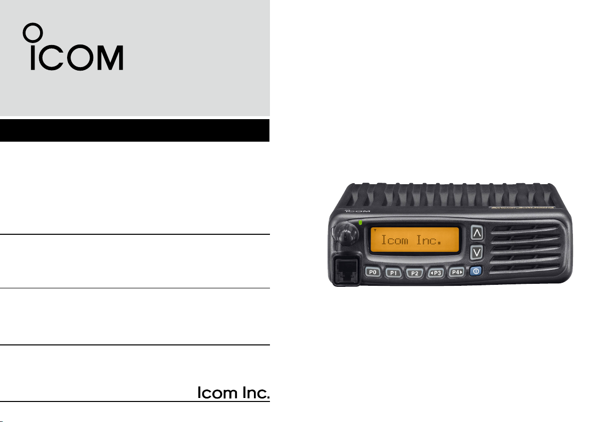
VHF dPMR MOBILE TRANSCEIVER
iF5062D
UHF dPMR MOBILE TRANSCEIVER
iF6062D
Page 2
IMPORTANT
EXPLICIT DEFENITIONS
READ ALL INSTRUCTIONS carefully and com-
pletely before using the transceiver.
SAVE THIS INSTRUCTION MANUAL — This
instruction manual contains important operating instructions
for the IC-F5062D VHF dPMR MOBILE TRANSCEIVER, IC-
F6062D UHF dPMR MOBILE TRANSCEIVER.
• This instruction manual includes some functions which
are usable only when they are pre-programmed by your
dealer. Ask your dealer for details.
• See the operating guide for details of BIIS (Binary Inter
change of Information and Signaling) and dPMR (dig
ital Private Mobile Radio) system operations. Ask your
dealer for details.
Icom, Icom Inc. and the Icom logo are registered trademarks of Icom Incorporated (Japan) in Japan, the United States, the United Kingdom, Germany,
France, Spain, Russia and/or other countries.
All other products or brands are registered trademarks or trademarks of their
respective holders.
i
-
-
WORD DEFINITION
RWARNING!
CAUTION
NOTE
Personal injury, fire hazard or electric
shock may occur.
Equipment damage may occur.
If disregarded, inconvenience only. No risk
of personal injury, fire or electric shock.
Page 3

PRECAUTIONS
RWARNING! NEVER connect the transceiver to an
AC outlet. This may pose a fire hazard or result in an electric
shock.
DO NOT use or place the transceiver in areas with tem-
peratures below –25°C or above +55°C, or in areas subject
to direct sunlight, such as the dashboard.
1
2
3
4
RWARNING! NEVER connect the transceiver to a
power source of more than 16 V DC or use reverse polarity.
This could cause a fire or damage the transceiver.
RWARNING! NEVER cut the DC power cable be-
tween the DC plug and fuse holder. If an incorrect connec
tion is made after cutting, the transceiver might be damaged.
CAUTION: NEVER place the transceiver where nor-
mal operation of the vehicle may be hindered or where it
could cause bodily injury.
CAUTION: NEVER allow children to touch the trans-
ceiver.
CAUTION: NEVER expose the transceiver to rain,
snow or any liquids.
USE the specified microphone only. Other microphones
have different pin assignments and may damage the trans
ceiver.
DO NOT operate the transceiver without running the ve-
hicle’s engine. The vehicle’s battery will quickly run out when
the transceiver transmits while the vehicle’s engine is OFF.
DO NOT place the transceiver in excessively dusty envi-
ronments.
-
DO NOT place the transceiver against walls. Otherwise
heat dissipation will be obstructed.
DO NOT use
when cleaning, as they damage the transceiver surfaces.
harsh solvents
such as benzine or alcohol
BE CAREFUL! The transceiver will become hot when
operating continuously for long periods.
-
5
6
7
8
9
10
11
12
13
14
15
16
ii
Page 4

VOICE CODING TECHNOLOGY
The AMBE+2™ voice coding Technology embodied in this
product is protected by intellectual property rights including
patent rights, copyrights and trade secrets of Digital Voice
Systems, Inc. This voice coding Technology is licensed
sole ly for use within this Communicatio ns Equipment.
The user of this Technology is explicitly prohibited from
attempting to extract, remove, decompile, reverse engineer,
or disassemble the Object Code, or in any other way convert
the Object Code into a human-readable form. U.S. Patent
Nos.
#5, 8 7 0 , 405, #5 , 8 26, 2 2 2 , #5 , 7 5 4 ,97 4 , #5 ,701 , 3 9 0 ,
#5, 7 1 5 , 365, #5 , 6 49, 0 5 0 , #5 , 6 3 0 ,01 1 , #5 ,581 , 6 5 6 ,
#5,517,511 , # 5,4 91,772, #5,247,57 9, #5,226,0 84 and
#5,195,166.
iii
Page 5

TABLE OF CONTENTS
IMPORTANT .......................................................................... i
EXPLICIT DEFENITIONS .....................................................i
PRECAUTIONS .................................................................... ii
VOICE CODING TECHNOLOGY ........................................ iii
TABLE OF CONTENTS ....................................................... iv
1
PANEL DESCRIPTION ................................................ 1–7
■ Front panel ................................................................... 1
■ Function display ...........................................................2
■ Programmable function keys ........................................3
2
BASIC OPERATION ..................................................8–15
■ Turning the power ON ..................................................8
■ Channel selection .........................................................8
■Call procedure ..............................................................9
■Receiving and transmitting ...........................................9
■User Set mode ...........................................................12
■ Emergency transmission ............................................13
■ Scrambler function .....................................................14
■ Stun function ..............................................................14
■ Priority A channel selection ........................................14
■ Forced Narrow function ..............................................15
■ Automatic Key Lock function ...................................... 15
■ Power Off Emergency function ...................................15
3
CONNECTION AND MAINTENANCE ....................16–20
■ Rear panel connection ...............................................16
■ Supplied accessories .................................................18
■ Mounting the transceiver ............................................18
■ Antenna ......................................................................19
■ Fuse replacement ......................................................19
■ Cleaning ..................................................................... 19
■ Options .......................................................................20
4
DOC ......................................................................... 21–23
1
2
3
4
5
6
7
8
9
10
11
12
13
14
15
16
iv
Page 6
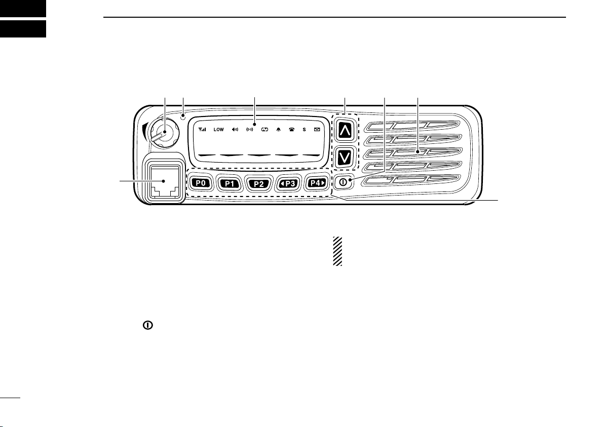
I c o m I n c .
q e
y
SpeakerFunction display (p. 2)
w r
t
1
PANEL DESCRIPTION
■ Front panel
q AF VOLUME CONTROL KNOB [VOL]
Rotate the knob to adjust the audio output level.
• Minimum audio level is preprogrammed.
w LED INDICATOR
➥ Lights red while transmitting a signal.
➥ Lights green while receiving a signal.
e UP/DOWN KEYS [CH Up]/[CH Down]
Push to select an operating channel, etc.
*Required functions can be assigned by your dealer. (p. 3)
r POWER SWITCH [ ]
Hold down for 1 second to turn the power ON or OFF.
• Automatic scan start, Password prompt and User Set mode access are available at power ON.
t DEALER-PROGRAMMABLE KEYS
Required functions can be programmed independently by
your dealer. (p. 3)
1
y MICROPHONE CONNECTOR
Connect the supplied or optional microphone.
NEVER connect non-specified microphones. The pin
assignments may be different and may damage the
transceiver.
D MICROPHONE
The supplied microphone has a PTT switch and a hanger.
• The following functions are available when you put the microphone
ON hook, or take it OFF hook (depending on the pre-programmed
settings):
- Automatic scan starts when you put it ON hook.
- Scan is paused or cancelled when you take it OFF hook.
- Automatically selects the Priority A channel when you take it OFF
hook.
- Sets to the ‘Inaudible’ (mute) mode when you put it ON hook.
-
Sets to the ‘Audible’ (unmute) mode when you take it OFF hook.
Page 7
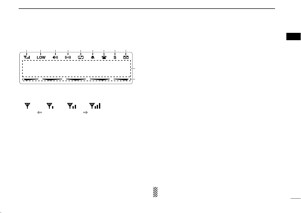
I c o m I n c.
!1
q w e r t y iu o
!0
PANEL DESCRIPTION
Weak Receive Signal level Strong
1
■ Function display
q SIGNAL STRENGTH ICON
Shows relative receive signal strength level.
w LOW POWER ICON
Appears when low output power is selected.
e AUDIBLE ICON
➥ Appears when the channel is in the ‘Audible’ (unmute)
mode.
➥ Appears when a matching signal is received.
r COMPANDER ICON
Appears when the Compander function is activated.
t SCRAMBLER ICON
Appears when the Voice Scrambler function is activated.
y BELL ICON
Appears/blinks when a matching signal is received, de-
pending on the pre-programmed settings.
u CALL CODE MEMORY ICON
Appears when the call code memory is selected.
i SCROLL ICON
Appears when an SDM (Short Data Message), including
more than 12 characters, is selected in the received mes
sage selection mode*
o SDM ICON
Appears when an SDM is received, or an SDM is selected
to transmit*
!0 ALPHANUMERIC DISPLAY
➥ Displays an operating channel number, channel name,
User Set mode contents, DTMF code, etc.
➥ Depending on the pre-programmed settings, characters
are displayed in 1 line or 2 lines on the LCD.
• In this instruction manual, the LCD illustration is described as
!1 ACTIVATED KEY ICON
Appears above the key assigned as [Scan], [Scan Add/
Del(Tag)], [Lock], [Talk Around], [Surveillance] and [BIIS
Button]*1, while that key is activated.
*1 BIIS operation only
*2 dPMR operation only
See the operating guide for details of BIIS
tem operations. Ask your dealer for details.
1, 2
.
having characters displayed in 2 lines.
1, 2
.
and dPMR sys-
1
2
3
4
-
5
6
7
8
9
10
11
12
13
14
15
16
2
Page 8

PANEL DESCRIPTION
1
■ Programmable function keys
The following functions can be assigned to [UP], [DOWN],
[P0], [P1], [P2], [P3] and [P4] programmable function keys.
Consult your Icom dealer or system operator for details con
cerning your transceiver’s programming.
If the programmable function names are bracketed in the fol
lowing explanations, the specific key is used to activate the
function, depending on the pre-programmed settings.
INFORMATION:
Depending on the pre-programmed settings, the pro
grammed function for
to [A], [B], [C] or [D] of the optional HM-152T, respectively. Ask your dealer for details.
CHANNEL UP, CHANNEL DOWN
➥ Push to select an operating channel.
➥ As described in the following topics, after pushing a pro-
grammed key, push [CH Up] or [CH Down] to select an
option, setting, etc.
ZONE
Push this key,
desired zone.
What is “zone”?—Certain channels are grouped together
and assigned to a zone, according to their intended use.
For example, ‘Staff A’ and ‘Staff B’ are assigned to a “Busi
ness” zone, and ‘John’ and ‘Cindy’ are assigned to a “Pri
3
vate” zone.
then push [CH Up] or [CH Down] to select the
[P0], [P1], [P2] or [P3] is assigned
ZONE UP, ZONE DOWN
Push to select an operating zone.
-
SCAN
➥ Push to start or cancel a scanning operation.
-
• When a scan is started by the Power ON Scan or Automatic
Scan function, push this key to cancel the scan. The cancelled
scan resumes after the pre-programmed time period.
➥
Hold down this key for 1 second to display the scan group,
-
-
-
then push [CH Up] or [CH Down] to select the desired one.
SCAN ADD/DEL (TAG)
➥ Push to add the selected channel to, or delete it from, the
scan group.
1. Push to display the scan group, and then push [CH Up] or
[CH Down] to select the desired one.
2. Push to add the channel to, or delete it from, the selected scan
group.
3. Hold down for 1 second to exit the scan group selection mode.
➥
While a scan is paused on a non-priority channel, push this
key to delete the selected channel from the scan group.
Depending on the pre-programmed settings, the cleared
channel is added to the scan group again after the scan
is cancelled. (Nuisance Delete function)
Page 9

PANEL DESCRIPTION
1
1
PRIORITY A, PRIORITY B
Push to select the Priority A or Priority B channel.
PRIORITY A (REWRITE), PRIORITY B (REWRITE)
➥ Push to select the Priority A or Priority B channel.
➥ Hold down for 1 second to assign the operating channel to
the Priority A or Priority B channel.
MEMORY CHANNELS 1, 2, 3, 4
Push to select memory channel 1, 2, 3 or 4.
MONITOR, MONITOR (AUDIBLE)
➥
Push to turn the CTCSS (DTCS) or 2/5-tone squelch mute
ON or OFF.
• Only during LMR (Land Mobile Radio) operation, push to
open any squelch, or deactivate any mute functions.
• Only during PMR (Private Mobile Radio) operation, push
to activate one or two of the following functions on each
channel (Depending on the pre-grogrammed settings):
- Hold down to unmute the channel (‘Audible’ mode).
- Push to mute the channel (‘Inaudible’ mode).
- After the communication is finished, push to send a ‘reset code’
(5-tone) or a ‘Clear Down’ signal (BIIS).
NOTE: T
return to the
grammed time period.
➥ Depending on the pre-programmed settings, holding down
this key for 1 second cancels a scan.
he
‘Audible’ (unmute)
‘Inaudible’ (mute)
mode may automatically
mode, after the pre-pro-
PUBLIC ADDRESS
Push to activate the PA (Public Address) function. When this
function is turned ON, the audio level can be separately con
trolled from the transceiver by pushing [CH Up] or [CH Down].
• This function can be used when external equipment, such as an
audio amplifier, speaker, etc. is connected.
• Push this key, then hold down [PTT] and speak into the microphone.
RX SPEAKER
Push to turn the RX Speaker function ON or OFF.
When this function is turned ON, the received audio can be
heard through an external speaker.
• This function is useful when you are away from the transceiver.
• The audio output level is linked to the transceiver’s volume control.
LIGHT
Push to turn the backlight ON for about 5 seconds, when the
Backlight function is set to “OFF” in the User Set mode.
LOCK
➥ Hold down this key until “LOCK ON” is displayed to elec-
tronically lock all programmable keys except the following:
[Moni], [Light], [Lock], [Call] (incl. Call A and Call B), [Emergency],
[Surveillance], [Lone Worker] and [OPT 1/2/3].
➥ When the Key Lock function is ON, hold down this key
until “LOCK OFF” is displayed to turn it OFF.
-
4
Page 10

PANEL DESCRIPTION
1
LONE WORKER
Push to turn the Lone Worker function ON or OFF.
• If the Lone Worker function is turned ON, and no operation occurs
during the pre-programmed time period, the Emergency function is
automatically turned ON.
HIGH/LOW
Push to select the transmit output power level temporarily or
permanently, depending on the pre-programmed settings.
• Ask your dealer for the output power level for each selection.
TONE/COLOUR CODE CH SELECT
➥ While in the analog mode, push to enter the continuous
tone selection mode. Then push [CH Up] or [CH Down] to
select the desired tone frequency/code setting. After se
lecting, push this key again to store the setting.
➥ While in the digital mode, push to enter the colour code
selection mode. Then push [CH Up] or [CH Down] to se
lect the desired colour code. After selecting, push this key
again to store the setting.
➥ While in the mixed (digital and analog) mode, push to enter
the continuous tone selection mode. Then push [CH Up] or
[CH Down] to select the desired tone frequency/code set
ting. After selecting, push this key to store the setting. After
that, the colour code selection screen appears. Push [CH
Up] or [CH Down] to select the desired colour code. After
selecting, push this key again to store the setting.
C.TONE CH ENT
Push to enter the continuous tone channel selection mode.
Then push [CH Up] or [CH Down] to select the desired tone
frequency/code setting. The selected channel remains set until
another channel is designated.
TALK AROUND
Push to turn the Talk Around function ON or OFF.
• The Talk Around function equalizes the transmit frequency to the
receive frequency for transceiver-to-transceiver communication.
WIDE/NARROW
Push to switch the IF bandwidth between wide and narrow.
• The wide passband width is pre-programmed to either 25.0 or
-
-
-
20.0 kHz by your dealer (PMR operation only).
DTMF AUTODIAL
Push to enter the DTMF channel selection mode, then push
[CH Up] or [CH Down] to select a desired DTMF channel.
After selecting, push again to transmit the selected DTMF
code.
RE-DIAL
Push to transmit the last-transmitted DTMF code.
• TX memories are cleared after turning the power OFF.
5
Page 11

PANEL DESCRIPTION
1
CALL, CALL A, CALL B
Push to transmit a 2/5-tone code or BIIS/dPMR call.
• Call transmission is necessar y before calling another station,
depending on your signalling system.
• [Call A] and/or [Call B] may be available when your system employs
selective ‘Individual/Group’ calls. Ask your dealer which call is
assigned to each key.
EMERGENCY
Hold down for the pre-programmed time period to enter the
emergency mode. After the pre-programmed time period, an
Emergency call is transmitted once, or repeatedly*. (p. 13)
• To exit the emergency mode, hold down this key for the pre-programmed time period again, before transmitting.
* Depending on the pre-programmed settings.
SURVEILLANCE
Push to turn the Surveillance function ON or OFF.
When this function is turned ON, the beep does not sound
and the LCD backlight and the LED indicator do not light, even
when a signal is received or a key is pushed.
TX CODE ENTER
Push to enter the TX code edit mode (5Tone)
ID code edit mode (BIIS, dPMR), and then set the desired TX
code or ID code
.
(p. 11)
or the
TX CODE CHANNEL SELECT
➥ Push to enter the TX code channel selection mode (p. 10)
or the ID selection mode (BIIS, dPMR), and then push
[CH Up] or [CH Down] to select the desired channel or ID.
➥ Hold down this key for 1 second to enter the
edit mode (5Tone)
dPMR), and then set the desired TX code or ID code
TX CODE CHANNEL UP, TX CODE CHANNEL DOWN
Push to select a TX code channel
SCRAMBLER
Push to turn the Voice Scrambler function ON or OFF.
COMPANDER
Push to turn the Compander function ON or OFF.
The Compander function reduces noise components from the
transmitted audio to provide clear communication.
ID-MR SELECT
➥ Recalls detected ID codes.
• Push this key, then push [CH Up] or [CH Down] to select the ID
code.
• Up to 5 IDs are memorized.
➥ Hold down for 1 second to erase the selected ID.
(p. 11)
or the ID code edit mode (BIIS,
(p. 10)
or ID (BIIS, dPMR).
TX code
.
1
See the operating guide for details of BIIS and dPMR system operations. Ask your dealer for details.
6
Page 12

PANEL DESCRIPTION
1
HOOK SCAN
When the Hook Scan function is pre-programmed, push this
key to disable the function. Push this key again to enable the
function.
USER SET MODE
➥ Hold down for 1 second to enter the User Set mode.
• In the User Set mode, push this key to select an item that is enabled by your dealer, and change the value or setting by pushing
[CH Up] or [CH Down].
➥ Hold down for 1 second again to exit the User Set mode.
The User Set mode is also available using the Power ON
function. Refer to page 12.
10Key ENT
Push to enable the microphone
• Depending on the pre-programmed settings, 10-keypad can be
used to select a desired memory channel, ID list number (dPMR),
TX status (BIIS, dPMR) or Short Data Message (dPMR), or enter a
desired TX code (5-tone) or ID (dPMR).
OPT 1 OUT, OPT 2 OUT, OPT 3 OUT
Push to output the control signal to the option connector. Ask
your dealer for details.
OPT 1 MOMENTARY, OPT 2 MOMENTARY,
OPT 3 MOMENTARY
Outputs the control signal to the option connector while holding down this key. Ask your dealer for details.
’s 10-keypad operation.
POWER OFF EMERGENCY
While holding down this key, turn the power OFF to activate
the Power OFF Emergency function.
This function makes the transceiver transmit emergency calls,
even though it appears to be powered OFF. (p. 15)
7
Page 13
BASIC OPERATION
KEY
NUMBER
0
5
4
9
3
8
2
7
1
6
2
■ Turning the power ON
q Hold down [ ] for 1 second to turn the power ON.
w If the transceiver is programmed for a start up password,
input the digit codes as directed by your dealer.
• The keys as below can be used for password input:
The transceiver detects numbers in the same block as identical.
Therefore “01234” and “56789” are the same.
e When the “PASSWORD” indication does not clear after
inputting 6 digits, the input code number may be incorrect.
Turn the power OFF and start over, in this case.
■ Channel selection
Several types of channel selection are available. Methods
may differ, according to your system set up.
NON-ZONE TYPE:
To select the desired operating channel:
• Push [CH Up] or [CH Down].
• Push one of [MR-CH 1] to [MR-CH 4].
ZONE TYPE:
To select the desired zone:
• Push [Zone], then push [CH Up] or [CH Down].
• Push [Zone Up] or [Zone Down].
D Voting operation
The transceiver automatically starts scanning when a zone,
specified for the voting operation, is selected.
The voting scan detects the signal strength of the repeaters,
and automatically selects the strongest one.
AUTOMATIC SCAN TYPE:
Channel setting is not necessary for this type. When turning
the power ON, the transceiver automatically starts scanning.
Scanning stops when receiving a call.
1
2
3
4
5
6
7
8
9
10
11
12
13
14
15
16
8
Page 14

Selective calling
Non-selective calling
BASIC OPERATION
2
■Call procedure
When your system employs tone signalling (excluding CTCSS
and
transmission. The tone signalling employed may be a selec
tive calling system, which allows you to call specific station(s)
only, and prevent unwanted stations from contacting you.
q Select the desired TX code channel according to your sys-
• This may not be necessary, depending on programming.
• Refer to pages 10 and 11 for details.
w Push [Call] (assigned to one of the dealer programmable
e After transmitting, the remainder of your communication
9
DTCS), a call procedure may be necessary prior to voice
tem operator’s instructions.
keys).
can be carried out in the normal fashion.
■Receiving and transmitting
Receiving:
q Hold down [ ] for 1 second to turn the power ON.
-
w Push [CH Up] or [CH Down] to select a channel.
e When receiving a call, rotate [VOL] to adjust the audio
output level to a comfortable listening level.
NOTE: Depending on the pre-programmed settings, the
transceiver automatically transmits the microphone audio
for the pre-programmed time period when a matching sig
nal is received.
• The HM-148G or HM-152 hand microphone is required.
Transmitting:
Wait for the channel to become clear to avoid interference.
q Take the microphone OFF hook.
• 2/5-tone mute may be released. (The ‘Audible’ (unmute) mode
is selected and LED indicator lights green.)
• The Priority A channel may be automatically selected.
w Wait for the channel to become clear.
• The channel is busy when the LED indicator lights green.
e While holding down [PTT], speak into the microphone at
your normal voice level.
r Release [PTT] to return to receive.
IMPORTANT: To maximize the readability of your signal;
1. Pause briefly after pushing [PTT].
2. Hold the microphone 5 to 10 cm from your mouth, then
speak into the microphone at a normal voice level.
-
Page 15

BASIC OPERATION
2
D Transmitting notes
• Transmit inhibit function
The transceiver has several inhibit functions which restrict
transmission under the following conditions:
- The channel is in the ‘Inaudible’ (mute) mode (“
ble icon) does not appear.)
- The channel is busy. However, depending on the preprogrammed settings, you can transmit when a call is re
ceived that includes an unmatching (or matching) CTCSS
(DTCS), colour code, or Individual or Talkgroup ID.
- The selected channel is a ‘receive only’ channel.
• Time-out timer
If continuous transmission exceeds the pre-programmed
time-out timer limit, the transmission is cut off.
• Penalty timer
After the transmission is cut off by the time-out timer, trans
mission is further inhibited for the pre-programmed penalty
timer period.
” (Audi-
D TX code channel selection
If the transceiver has a key assigned to TX Code CH Select,
the indication can be toggled between the operating channel
number (or name) and TX code channel number (or name).
When the TX code channel number (or name) is displayed,
[CH Up] or [CH Down] selects the TX code channel.
-
USING [TX CODE CH SELECT]:
q Push [TX Code CH Select]— a TX code channel number
(or name) appears.
w Push [CH Up] or [CH Down] to select the desired TX code
channel.
e After selecting, push [TX Code CH Select] to set.
• Return to the stand-by mode.
r Push [Call] to transmit the selected TX code.
USING [TX CODE CH UP]/[TX CODE CH DOWN]:
If the transceiver has a key assigned to TX Code CH Up or
TX Code CH Down, the programmed TX code channel can
be directly selected when pushed.
1
2
3
4
5
6
7
8
9
10
11
12
13
14
15
16
10
Page 16

BASIC OPERATION
2
D TX code edit (5-tone operation only)
If the transceiver has a key assigned to TX Code CH Select
or TX Code Enter, TX code contents can be edited within the
allowable digits.
USING [TX CODE CH SELECT]:
q Push [TX Code CH Select] to enter the TX code channel
selection mode.
• Select the desired channel before entering the TX code channel selection mode, if necessary.
w Hold down [TX Code CH Select] for 1 second to enter the
TX code edit mode.
• The digit to be edited blinks.
e Push [TX Code CH Select] to select the desired digit to
be edited.
r Push [CH Up] or [CH Down] to set the desired digit.
t Push [TX Code CH Select] to set. The digit to the right will
automatically blink.
y Repeat steps r and t to edit all allowable digits.
u After editing, push [TX Code CH Select] to set.
• Return to the stand-by mode.
i Push [Call] to transmit.
USING [TX CODE ENTER]:
q Push [TX Code Enter] to enter the TX code edit mode.
• The digit to be edited blinks.
w Push [TX Code Enter] to select the desired digit to be ed-
ited.
e Push [CH Up] or [CH Down] to select the desired digit.
r Push [TX Code Enter] to set. The digit to the right will au-
tomatically blink.
t Repeat steps e and r to input all allowable digits.
y After editing, push [TX Code Enter] to set.
• Return to the stand-by mode.
u Push [Call] to transmit.
D DTMF transmission
If the transceiver has a key assigned to DTMF Autodial, the
automatic DTMF transmission function is available. Up to 8
DTMF channels are selectable.
q Push [DTMF Autodial]— a DTMF channel appears.
w Push [CH Up] or [CH Down] to select the desired DTMF
channel.
e Push [DTMF Autodial] to transmit the DTMF code.
11
Page 17

BASIC OPERATION
[P1] [P2] [ ]
[P0]
[P0] [Up]/[Down]
[ ]
2
■User Set mode
The User Set mode can be accessed with the Power ON
function. In this case, all items are selectable.
The User Set mode allows you to set seldom-changed settings and you can “customize” the transceiver operation to
suit your preferences and operating style.
NOTE: While in the User Set mode, [Up], [Down] and [P0]
activate regardless of the assigned key functions.
Entering the User Set mode:
q While holding down [P1] and [P2], push [ ] to turn the
power ON.
• Turn the power OFF first.
• You should hold down [P1] and [P2] until “SET MODE” appears
on the display.
w Hold down [P0] for 1 second to enter the User Set mode.
e Push [P0] several times to select the appropriate item.
Then, push [Up] or [Down] to set the desired value or set
ting.
• Available User Set mode items are Backlight, LCD Contrast,
Beep, Beep Level, Ringer Level, SQL Level, AF Min Level,
Mic Gain, Battery Voltage, Horn, Signal Moni, Lone Worker
and System Info.
r Hold down [ ] for 1 second to turn the power OFF, then
turn the power ON again to exit the User Set mode.
The User Set mode is also available using a programmable
key. Please refer to page 7 [User Set Mode] section for instructions regarding using the key assigned to the User Set
Mode.
[User Set Mode] allows for quick item selection. Set “Enable”
for the often used items using the CS-F3160/F5060 (dPMR)
cloning software. Ask your dealer for details.
1
2
-
3
4
5
6
7
8
9
10
11
12
13
14
15
16
12
Page 18

BASIC OPERATION
2
■ Emergency transmission
When [Emergency] is held down for the pre-programmed time
period, the emergency call is transmitted once, or repeat
edly*, on the specified emergency channel.
* Depending on the pre-programmed settings.
A repeat emergency call is automatically transmitted until
you turn the power OFF. Depending on the pre-programmed
settings, receiving a matching 5-tone code cancels the trans
mission.
When no emergency channel is specified, the call is trans
mitted on the operating channel.
If you want to cancel the Emergency function, hold down
[Emergency] for the pre-programmed time period again be
fore transmitting the call.
If your transceiver is programmed for Silent operation, you
can transmit emergency calls without the beep sounding and
the LED indicator lighting.
IMPORTANT: We recommend that you have an emergency channel to provide reliable emergency calls. Ask
your dealer for details.
D NOTES
-
Depending on the pre-programmed settings, the following
functions are automatically activated.
• Auto TX function
After an emergency call transmission, audio from the micro-
-
-
-
phone is automatically transmitted for the pre-programmed
time period.
• The HM-148G or HM-152 hand microphone is required.
• Auto RX function
The transceiver stands by in the ‘Audible’ (unmute) mode
for the pre-programmed time period, after the emergency
call transmission.
13
Page 19

BASIC OPERATION
2
■ Scrambler function
The Voice Scrambler function provides private communication between stations. All versions have a built-in frequency
inversion type scrambler. Moreover, the optional Rolling or
Non-rolling type can be used.
➥ Push [Scrambler] to turn the Voice Scrambler function ON
or OFF.
• “ ” appears when the function is ON.
■ Stun function
The dispatcher can send a signal that will stun, kill or revive
your transceiver.
When a Stun command is received, the transceiver becomes
unusable. In that case, receiving a Revive command or input
ting the password* (p. 8) is necessary to operate the trans
ceiver again.
When a Kill command is received, the transceiver becomes
unusable (the transceiver switches to the cloning required
condition). In that case, cloning the transceiver is necessary
to operate the transceiver again.
* Depending on the pre-programmed settings.
■ Priority A channel selection
When one of the following operations is performed, the
transceiver automatically selects the Priority A channel.
• Turning the power ON
The Priority A channel is selected each time the trans
ceiver power is turned ON.
• Auto Reset
The Priority A channel is selected when the Auto Reset
timer ends.
• OFF hook
The Priority A channel is selected when you take the mi
crophone OFF hook.
-
-
1
2
3
4
-
5
6
7
8
9
-
10
11
12
13
14
15
16
See the operating guide for details of the Stun function
with the BIIS and dPMR system operations. Ask your
dealer for details.
14
Page 20

BASIC OPERATION
2
■ Forced Narrow function
Depending on the pre-programmed settings, you can turn the
Forced Narrow function ON or OFF.
When the function is ON, the channel width becomes Narrow
regardless of the channel setting, the [Wide/Narrow] key op
eration, repeater setting, or PC control command.
To activate or cancel the Forced Narrow function, turn the
power ON while holding down both [P1] and [PTT].
Depending on the pre-programmed settings, the Forced Nar
row function is initially turned ON by your dealer.
■ Automatic Key Lock function
When the transceiver has a key assigned to Lock, the Automatic Key Lock function can be used.
When no operation occurs during the pre-programmed time
period, the function automatically activates the Key Lock
function.
When the Key Lock function is ON, hold down [Lock] until
“LOCK OFF” is displayed to turn it OFF.
■ Power Off Emergency function
When the transceiver has a key assigned to Power OFF
Emergency, you can use the function.
This function makes the transceiver transmit emergency calls,
even though it appears to be powered OFF.
-
To activate the Power OFF Emergency function, turn the
power OFF while holding down [Power OFF Emergency].
When the function is activated, any key operation, the ON/OFF
Hook and Lone Worker functions become invalid. The beep,
LED indicator, display and speaker are turned OFF as well.
On the other hand, the transceiver can transmit emergency
calls according to the pre-programmed emergency settings.
Depending on the pre-programmed settings, the Ambience
Listening function can also be used. (dPMR operation only)
To cancel the Power OFF Emergency function and restore
the transceiver, turn the power ON.
1515
Page 21

CONNECTION AND MAINTENANCE
Black
Red
12V
Battery
q
D-Sub 25-pin
Connect to external
equipment.
t
r
y
Optional
speaker
e
w
Microphone
ANTENNA CONNECTOR
Connects to the antenna. Ask your dealer
about antenna selection and placement.
EXTERNAL SPEAKER JACK
Connect a 4–8 ø external speaker.
eq
w
MICROPHONE HANGER
Connect the supplied microphone
hanger to the vehicle’s ground for the
ON/OFF Hook functions. (See page 1)
IGNITION LEAD
Connects to an ignition line.
R
DC POWER
RECEPTACLE
Connects to a 12 V
DC battery. Pay attention to polarities.
Do not put a pressure to this lead.
Binding to the DC power cable is
recommended.
r
t
y
Solder
Crimp
NOTE: Use the terminals as shown
below for the cable connections.
Antenna
R WARNING! NEVER
connect to a 24 V battery. This could damage the transceiver.
R WAR N I N G! NEVE R
remove the fuse-holders
from the DC power cable.
3
■ Rear panel connection
D For mobile operation
1
2
3
4
5
6
7
8
9
10
11
12
13
14
15
16
16
16
Page 22

CONNECTION AND MAINTENANCE
ANTENNA CONNECTOR
IGNITION LEAD
D-Sub 25-pin
Connect to external equipment.
MICROPHONE HANGER
Connect the supplied microphone hanger to ground
for the ON/OFF Hook functions. (See page 1)
EXTERNAL
SPEAKER JACK
Connect a 4–8 ø
external speaker.
DC POWER
RECEPTACLE
Connects to a 13.2 V
DC power supply. Pay
attention to polarities.
Make sure the ground
terminal of the DC
power supply is
grounded.
q
w
r
Optional speaker
e
t
Microphone
y
To the antenna
DC power
supply 13.2 V
to an
AC
outlet
Fuses
10 A
Black
Red
q
w
e
r
t
y
R WAR N I N G! NEVE R
remove the fuse-holders
from the DC power cable.
3
■ Rear panel connection (Continued)
D For base station operation
17
Page 23

CONNECTION AND MAINTENANCE
Flat washer
Felt*
Spring washer
When using
self-tapping screws
Felt*
*Felt reduces the effects of vibration.
Microphone
Microphone hanger
and screw set
Microphone
hanger cable
DC power cable Sponges*
2
Flat washers
Spring washers
Bracket bolts
Mounting screws
(5×12)
Self-tapping screws
(5×16)
Nuts
Function name
stickers*
1
*
2
Used for labelling the programmable
function keys according to their
assinged functions.
Used for optional unit installation.
Ask your dealer for details.
*
1
Mounting bracket
3
■ Supplied accessories ■ Mounting the transceiver
1
The universal mounting bracket supplied with your transceiver allows overhead or dashboard mounting.
• Mount the transceiver securely with the 4 supplied screws
to a thick surface which can support more than 1.5 kg.
2
3
4
5
6
7
8
9
10
11
12
13
14
15
16
18
Page 24

CONNECTION AND MAINTENANCE
3
■ Antenna
A key element in the performance of any communication systems is the antenna. Contact your dealer about antennas and
the best places to mount them.
■ Fuse replacement
A fuse is installed in each fuse holder of the supplied DC
power cable. If a fuse blows, or the transceiver stops function
ing, track down the source of the problem, have it repaired,
and replace the damaged fuse with a new rated one.
❑ Fuse rating: 10 A
USE a 10 A fuse of the same type only.
■ Cleaning
If the transceiver becomes dusty or dirty, wipe it clean with a
soft and dry cloth.
DO NOT use harsh solvents such as benzine or alcohol, as they damage the transceiver surfaces.
-
19
Page 25

CONNECTION AND MAINTENANCE
3
■ Options
• RMK-3 separation kit + OPC-607/OPC-608/OPC-609 sep-
aration cable
Allows you to install the transceiver main unit separately
from the front panel for operating convenience.
OPC-607 : 3 m
OPC-608 : 8 m
OPC-609 : 1.9 m
•
OPC-1132A dc power cable
OPC-1132A : 3 m
• SP-10/SP-22/SP-30 external speakers
Input impedance : 4 ˘
Max. input power : 5 W (SP-10/SP-22), 40 W (SP-30)
SP-10 : For all-round mobile operation.
SP-22 : Compact and easy-to-install.
SP-30 : High input power level.
• HM-152/HM-152T/HM-148G/HM-148T hand microphones
HM-152 : Hand microphone
HM-152T : DTMF microphone
HM-148G : Self grounding heavy duty microphone
HM-148T : Self grounding heavy duty microphone with 10-
keypad
The 10-keypad of this microphone can be used
for the DTMF code transmission only.
• SM-25 desktop microphone
• UT-96R 5tone unit
Provides 5-tone decoder capabilities.
• UT-108R dtmf decoder unit
Provides DTMF decoder capabilities.
• UT-109R/UT-110R scrambler units
Non-rolling type (UT-109R)/Rolling type (UT-110R) voice
scrambler unit provides high communication security.
Approved Icom optional equipment is designed for optimal
performance when used with an Icom transceiver.
Icom is not responsible for the destruction or damage to an
Icom transceiver in the event it is used with equipment that
is not manufactured or approved by Icom.
Some options may not be available in some countries. Please
ask your dealer for details.
1
2
4
5
6
7
8
9
10
11
12
13
14
15
16
20320
Page 26

2121
Type-designation
DECLARATION
OF CONFORMITY
We Icom Inc. Japan
1-1-32, Kamiminami, Hirano-ku
Osaka 547-0003, Japan
Kind of equipment :
VHF TRANSCEIVER
Signature
Authorized representative name
Place and date of issue
Declare on our sole responsibility that this equipment complies with the
essential requirements of the Radio and Telecommunications Terminal
Equipment Directive, 1999/5/EC, and that any applicable Essential Test
Suite measurements have been performed.
Version (where applicable):
This compliance is based on conformity with the following harmonised
standards, specifications or documents:
i)
ii)
iii)
iv)
v)
vi)
vii)
136–174 MHz 12.5 KHz/25 KHz
136–174 MHz 12.5 KHz/20 KHz
136–174 MHz 6.25 KHz
Düsseldorf
15th Feb. 2008
Y. Furukawa
General Manager
EN 60950-1 2001
EN 301 489-1 v1.4.1 (August 2002)
EN 301 489-5 v1.3.1 (August 2002)
EN 300 086-2 v1.1.1 (March 2001)
EN 300 219-2 v1.1.1 (March 2001)
EN 300 113-2 v1.3.1 (December 2003)
EN 301 166-2 v1.1.1 (December 2001)
(Variant name
4
DOC
The IC-F5062D and IC-F6062D comply with
the essential requirements of the European
Radio and Telecommunication Terminal Direc
tive 1999/5/EC.
-
This war ning symbol indicates that this equip
ment operates i n non- har monised frequen cy
bands and/or may be subject to licensing condi
tions in the country of use. Be sure to check that
you have the correct version of this radio or the
correct programming of this radio, to comply with
national licensing requirement.
-
-
Page 27

DECLARATION
OF CONFORMITY
We Icom Inc. Japan
1-1-32, Kamiminami, Hirano-ku
Osaka 547-0003, Japan
Signature
Authorized representative name
Place and date of issue
Declare on our sole responsibility that this equipment complies with the
essential requirements of the Radio and Telecommunications Terminal
Equipment Directive, 1999/5/EC, and that any applicable Essential Test
Suite measurements have been performed.
Version (where applicable):
This compliance is based on conformity with the following harmonised
standards, specifications or documents:
i)
ii)
iii)
iv)
v)
vi)
vii)
400–470 MHz 12.5 KHz/25 KHz
400–470 MHz 12.5 KHz/20 KHz
400–470 MHz 6.25 KHz
Y. Furukawa
General Manager
Düsseldorf
15th Feb. 2008
EN 60950-1 2001
EN 301 489-1 v1.4.1 (August 2002)
EN 301 489-5 v1.3.1 (August 2002)
EN 300 086-2 v1.1.1 (March 2001)
EN 300 219-2 v1.1.1 (March 2001)
EN 300 113-2 v1.3.1 (December 2003)
EN 301 166-2 v1.1.1 (December 2001)
Type-designation
Kind of equipment :
UHF TRANSCEIVER
(Variant name
DOC
4
1
2
3
4
5
6
7
8
9
10
11
12
13
14
15
16
22
Page 28

DOC
4
• List of Country codes (ISO 3166-1)
Country Codes Country Codes
1
Austria
2
Belgium
3
Bulgaria
4
Croatia
5
Czech Republic
6
Cyprus
7
Denmark
8
Estonia
9
Finland
10
France
11
Germany
12
Greece
13
Hungary
14
Iceland
15
Ireland
16
Italy
17
Latvia
AT
BE
BG
HR
CZ
CY
DK
EE
FI
FR
DE
GR
HU
IS
IE
IT
LV
18
Liechtenstein
19
Lithuania
20
Luxembourg
21
Malta
22
Netherlands
23
Norway
24
Poland
25
Portugal
26
Romania
27
Slovakia
28
Slovenia
29
Spain
30
Sweden
31
Switzerland
32
Turkey
33
United Kingdom
LI
LT
LU
MT
NL
NO
PL
PT
RO
SK
SI
ES
SE
CH
TR
GB
23
About e-marking: Detailed installation notes for Icom
mobile transceivers to be fitted into vehicles are available.
Please contact your Icom dealer or distributor.
Page 29

MEMO
1
2
3
4
5
6
7
8
9
10
11
12
13
14
15
16
Page 30

MEMO
Page 31

MEMO
1
2
3
4
5
6
7
8
9
10
11
12
13
14
15
16
Page 32

< Intended Country of Use >
AT
FI
IT
PL
GB
RO
BE
FR
LV
PT
IS
TR
CY
DE
LT
SK
LI
HR
CZ
GR
LU
SI
NO
DK
HU
MT
ES
CH
EE
IE
NL
SE
BG
A-6841H-1EU
Printed in Japan
© 2010 Icom Inc.
Printed on recycled paper with soy ink.
1-1-32 Kamiminami, Hirano-ku, Osaka 547-0003, Japan
 Loading...