


INSTRUCTION MANUAL
UHF TRUNKED RADIOS
iF43GT/GS
iF44GT/GS

PRECAUTIONSIMPORTANT
READ ALL INSTRUCTIONS carefully and com-
pletely before using the transceiver.
SAVE THIS INSTRUCTION MANUAL — This
instruction manual contains important operating instructions
for the IC-F43GT/GS, F44GT/GS UHF TRUNKED RADIOS.
R CAUTION! NEVER hold the transceiver so that
the antenna is very close to, or touching exposed parts of
the body, especially the face or eyes, while transmitting. The
transceiver will perform best if the microphone is 5 to 10 cm
away from the lips and the transceiver is vertical.
R CAUTION! NEVER operate the transceiver with a
headset or other audio accessories at high volume levels.
EXPLICIT DEFINITIONS
WORD DEFINITION
RDANGER
RWARNING
CAUTION
NOTE
Icom, Icom Inc. and the Icom logo are registered trademarks of Icom Incor-
porated (Japan) in the United States, the United Kingdom, Germany, France,
Spain, Russia and/or other countries.
i
Person al death , s eriou s injury or a n
explosion may occur.
Personal injury, fire hazard or electric
shock may occur.
Equipment damage may occur.
If disregarded, inconvenience only. No risk
of personal injury, fire or electric shock.
R CAUTION! NEVER short the terminals of the bat-
tery pack.
DO NOT push PTT when not actually desiring to transmit.
DO NOT use or place the transceiver in direct sunlight or
in areas with temperatures below –25°C or above +55°C.
The basic operations, transmission and reception of the
transceiver are guaranteed within the specified operating
temperature range. However, the LCD display may not be
operate correctly, or show an indication in the case of long
hours of operation, or after being placed in extremely cold
areas.

DO NOT modify the transceiver for any reason.
KEEP the transceiver from the heavy rain, and Never im-
merse it in water. The transceiver construction is
sistant, not waterproof.
The use of non-Icom battery packs/chargers may impair
transceiver performance and invalidate the warranty.
water re-
Icom optional equipment is designed for optimal perfor
mance when used with this transceiver. We are not respon
sible for the transceiver being damaged or any accident
caused when using non-Icom optional equipment.
-
-
ii

TABLE OF CONTENTS
IMPORTANT .......................................................................... i
EXPLICIT DEFINITIONS ....................................................... i
PRECAUTIONS ..................................................................... i
TABLE OF CONTENTS ....................................................... iii
1
ACCESSORIES ...........................................................1–3
■ Supplied accessories ...................................................1
■ Accessory attachments ................................................1
2
PANEL DESCRIPTION ................................................ 4–6
■ Front panel ...................................................................4
■ Function display ...........................................................6
3
BASIC OPERATION ..................................................7–20
■ General.........................................................................7
■ Calling ..........................................................................8
■ Calling with the keypad (10-key version only) ............12
■ Special call with the keypad .......................................17
■ Receiving a call ..........................................................17
4
DISPLAYING MESSAGES ............................................21
5
OTHER FUNCTIONS ...............................................22–25
■ PTT quick call ............................................................. 22
■ Call back function .......................................................22
■ Calling station ID indication for group call ..................23
■ System lock function ..................................................24
■ Call code memory ......................................................24
■ Automatic transmit output power selection .................24
■ Power ON security...................................................... 24
■ Voice scrambler ..........................................................25
■ DTMF operation .........................................................25
■ Compander function ...................................................25
6
USER SET MENU ...................................................26–27
■ User set menu ............................................................26
7
TALK AROUND .............................................................28
8
PROGRAMMABLE FUNCTIONS............................29–30
■ Programmable function keys ......................................29
9
OPTIONAL UNIT INSTALLATION ................................31
■ UT-109 and UT-110 installation ..................................31
10
BATTERY CHARGING ............................................32–36
■ Caution .......................................................................32
■ Optional battery chargers ...........................................34
11
OPTIONAL BATTERY CASE ........................................37
■ Battery case (BP-240) ................................................37
12
OPTIONAL SWIVEL BELT CLIP ............................38–39
■ MB-93 contents ..........................................................38
■ Attaching ....................................................................38
■ Detaching ...................................................................39
13
OPTIONS .................................................................40–41
14
DOC ............................................................................... 42
iii

q w
r
e
t
ACCESSORIES
1
■ Supplied accessories
The following accessories are supplied: Qty.
q Flexible antenna ...............................................................1
w Battery pack ..................................................................... 1
e Belt clip ............................................................................1
r Unit cover (double-sided tape)* ........................................1
t Jack cover (with screws) ............................................ 1 set
*Use the unit cover as a spare. Ask your dealer for details.
■ Accessory attachments
D Flexible antenna
Connect the supplied flexible an-
tenna to the antenna connector.
CAUTION:
• NEVER HOLD the antenna
when carrying the transceiver.
• Transmitting without an antenna
may damage the transceiver.
1
2
3
4
5
6
7
8
9
10
11
12
13
14
15
16
1

ACCESSORIES
q
w
q
w
1
D Battery pack
To attach the battery pack:
Slide the battery pack in the direction of the arrow (
lock it with the battery release button.
• Slide the battery pack until the battery release button makes a ‘click’
sound.
To release the battery pack:
Push the battery release button in the direction of the arrow
(w) as shown below. The battery pack is then released.
NEVER release or attach the battery pack when the trans-
ceiver is wet or soiled. This may result water or dust get
ting into the transceiver/battery pack and may result in the
transceiver being damaged.
q), then
D Belt clip
To attach the belt clip:
q Release the battery pack if it is attached.
w Slide the belt clip in the direction of the arrow until the belt
clip is locked and makes a ‘click’ sound.
-
To detach the belt clip:
q Release the battery pack if it is attached.
w Pinch the clip (q), and slide the belt clip in the direction of
the arrow (w).
2

q
w
q
w
ACCESSORIES
1
D Jack cover
Attach the jack cover when the optional speaker-microphone
is not used.
To attach the jack cover:
q Attach the jack cover on
the [SP]/[MIC] jack.
w Tighten the screws.
To detach the jack cover:
q Unscrew the screws with
a Phillips screwdriver.
w Detach the jack cover for
the speaker-microphone
connection.
1
2
3
4
5
6
7
8
9
10
11
12
13
14
15
16
3

q
w
e
r
t
u
10-keypad version
y
i
o
!0
!1
!2
!3
Function display
(p. 6)
[SP]/[MIC] jack cover
NOTE: Attach the [SP]/[MIC] jack
cover when the optional speaker-
microphone is not used.
(See p. 3 for details)
2
PANEL DESCRIPTION
■ Front panel
e EMERGENCY KEY [RED]
➥ Push and hold for 2 sec. to start the emergency call to
the specified number (Emergency call; p. 15).
➥“EMRGENCY” is displayed while pushing and holding.
r [SP]/[MIC] JACK
Connect the optional speaker-microphone.
t MODE KEY [P2] (p. 28)
q GROUP SELECTOR
Rotate to select the pre-programmed group code chan-
nel.
w VOLUME CONTROL [VOL]
Rotate to turn the power ON/OFF and adjusts the audio
level.
4
Push to toggle between conventional and trunking opera
tion modes.
y HIGH/LOW KEY [P3]
Push to toggle the transmit output power.
• When automatic power selection is enabled for trunking mode
operation, the transmit output power cannot be selected with this
key.
-

PANEL DESCRIPTION
2
1
u 10-KEYPAD (Depending on version)
The keypad allows you to enter digits to:
• Set TX codes
• Set DTMF codes (during transmit)
• Input text message for SDM operation
• Start up with the password
i DESPATCHER KEY [P0] (p. 10)
➥Push to display despatcher call conditions.
➥Push again to display the status code, if permitted.
➥Push again to return to stand-by condition.
o CALL BACK KEY [P1] (p. 22)
➥ Push to display the received call record (call back mem-
ory) that had not replied.
➥Push again to return to stand-by condition.
➥ Push and hold for 2.5 sec. to toggle the call back mode
ON and OFF.
• When the call back mode is set to ON, the received call is
stored into record (log), and the call back message is send
back to the calling station automatically.
!0 UP/DOWN KEYS
➥Push to select the call memory channel.
➥Push to select the call back memory channel.
➥Push to select the status channel.
➥ Push to select the operating channel. (Conventional
mode operation only)
➥ Push to select the setting value or condition during user
set mode.
➥ Push to erase the previously entered digit number
(functions as back space key) during dialing number
entering from the keypad. (10-key version only)
!1 PTT SWITCH [PTT]
➥ Push to making a call with the displayed dialing num-
ber.
➥ When selecting a traffic channel for communication, or
conventional mode, push to transmit.
➥ When an individual call is received, push to reply the
call.
!2 CLEAR (SET MODE) KEY (pgs. 8, 26)
➥Push to finish the communication.
➥Push and hold to enter to the user set menu.
➥ During some function operation, push to return to stand-
by condition.
!3 ANTENNA CONNECTOR
Connects the supplied antenna.
Desired functions can be programmed into the [P0] to [P3],
[Red], [Clear], [Up] and [Down] keys independently by your
dealer. (p. 29)
2
3
4
5
6
7
8
9
10
11
12
13
14
15
16
5

q !1!0oiuytrew
!2
!3
!4
6
PANEL DESCRIPTION
2
■ Function display
q TRANSMIT INDICATOR
Appears while transmitting.
w BUSY INDICATOR
Appears while the channel is busy.
e OVER-FLOW INDICATOR
Appears when the received SDM including more than 9
characters is displayed.
r SIGNAL STRENGTH INDICATOR
Appears when receiving a signal and shows the signal
strength levels in 4-steps.
• No bars appear and “ ” blinks when the transceiver is in out-of
service area. For stable communications, the transceiver should
be in the area that the S-meter indicator shows the full scales (3
bars) indication.
t LOW POWER INDICATOR
Appears when low output power is selected.
• When the battery power decreases to a specified level, low
power is selected automatically.
y AUDIBLE INDICATOR
Appears when the voice communication can be per-
formed.
u COMPANDER INDICATOR
Appears when the compander function is activated.
• The compander function improves communicating audio quality.
i SCRAMBLER INDICATOR
Appears when the voice scrambler function is activated.
o CALL BACK INDICATOR
➥Blinks when an individual call is received.
➥ Appears when individual calls that the call back opera-
tion has not been performed are available.
➥Disappears when replies to all individual calls.
!0 PRIMARY NETWORK INDICATOR
Appears when the transceiver is in the primary network
service area.
!1 KEY LOCK INDICATOR
Appears when the key lock function is turned ON.
!2 BATTERY INDICATOR
Appears or blinks when the battery power decreases to a
specified level.
!3 ALPHANUMERIC DISPLAY
Shows dialing number and received message, etc.
!4 SYSTEM LOCK INDICATOR
Appears when the system lock function is in use.

BASIC OPERATION
3
■ General
Rotate [VOL] to turn the transceiver power ON.
Beeps sound, and the following contents will be displayed in
sequence.
• Opening text
• Prefix code
• Individual code (2 or 3-digit)
• Memory group code (or text name)
- The selected memory group code (selected by [Group se
lector]) and “
the trunking service area, and the desired call can be
made. (The text name is displayed if programmed instead
of the group code.)
- “
” blinks when the transceiver is in out-of-service area,
or the system is fall down. The transceiver searching for an
operatable system base in this case.
- “
” appears when the control signal from the base station
that the system ID (AAD number) is registered in primary
network.
(3-digit)/Fleet code (4-digit)
” are displayed when the transceiver is in
e.g.: When the Prefix code is ‘201,’ Fleet code is ‘2001,’ Indi
vidual code is ‘300’ and Group code is ‘90,’ “201/2001”,
“300” and “90” are displayed in sequence after turning
the transceiver ON.
(Opening text)
Opening text is displayed.
-
Prefix code/Fleet code is dis-
played.
⇓
201/2001
⇓
300
Individual code is displayed.
⇓
90
A group code is displayed
when no text name is pro-
grammed.
1
-
2
3
4
5
6
7
8
9
10
11
12
13
14
15
16
7

BASIC OPERATION
3
■ Calling
The following call operations can be performed using the pre-
programmed dialing number.
D Group call
Select the desired group code that is stored in the memory
using [Group selector] or [Up]/[Down].
Up to 16 group codes with [Group selector], up to 40 group
codes with [Up]/[Down] can be selected.
q Rotate [Group selector] or [Up]/[Down] to select the de-
sired group code.
GROUP 1
The pre-programmed text
name is displayed.
90
When no text name is pro-
grammed, a group code is
displayed.
w Push [PTT] or [Call Set Up] to make a group call.
• “CALLING” is displayed and the calling beeps sound.
CALLING
e When the call is succeeded, “CONNECT” and “ ” appear,
and communication can be made.
• The communication timer starts count down at the same time.
(When no transmission time limit is set, the timer counts up.)
CONNECT
TIM 0 56
r The warning beeps sound 10 sec. before the communica-
tion timer is activated.
• The communication is disconnected automatically when the
communication timer is activated.
t Push [Clear] to disconnect the communication manually.
• Pushing [M] and [#] in sequence also disconnect the communi-
cation. (10-key version only)
CLR DOWN
8

BASIC OPERATION
3
1
D Individual call
Select the desired individual code with [Up]/[Down].
q Push [Up]/[Down] to select the desired individual code.
PERSON 1
The pre-programmed text
name is displayed.
20 302
When no text name is pro-
grammed, the dialing num-
ber is displayed.
w Push [PTT] or [Call Set Up] to make an individual call.
• “CALLING” is displayed and calling beeps sound.
CALLING
e When the call is succeeded, “CONNECT” and “ ” appear,
and communication can be made.
• The communication timer starts count down at the same time.
(When no transmission time limit is set, the timer counts up.)
CONNECT
TIM 0 56
r The warning beeps sound 10 sec. before the communica-
tion timer is activated.
• The communication is disconnected automatically when the
communication timer is activated.
t Push [Clear] to disconnect the communication manually.
• Pushing [M] and [#] in sequence also disconnect the communi-
cation. (10-key version only)
CLR DOWN
2
3
4
5
6
7
8
9
10
11
12
13
14
15
16
9

BASIC OPERATION
3
D Despatcher call
A status is used for the despatcher call normally, however, the
direct despatcher call can be made according to the setting.
q Push [Despatcher] to select the despatcher call condition.
• “DESPATCH” is displayed.
DESPATCH
w Push [PTT] or [Call Set Up] to make the despatcher call.
• When the direct despatcher call is inhibited, the status message
“0 (call back request)” is transmitted, then returns to stand-by
condition.
• “CALLING” is displayed and the calling beeps sound.
CALLING
e When the call is succeeded, “CONNECT” and “ ” appear,
and communication can be made.
• The communication timer starts count down at the same time.
(When no transmission time limit is set, the timer counts up.)
CONNECT
TIM 0 56
r The warning beeps sound 10 sec. before the communica-
tion timer is activated.
• The communication is disconnected automatically when the
communication timer is activated.
t Push [Clear] to disconnect the communication manually.
• Pushing [M] and [#] in sequence also disconnect the communi-
cation. (10-key version only)
CLR DOWN
10

BASIC OPERATION
3
D Status call
A status message can be sent to the individual or despatcher
station.
The status message cannot be sent to a group stations.
• Individual status call
q Push [Up]/[Down] to select the desired individual code.
PERSON 1
w Push [Status] to enter the status message selection
mode.
e Push [Up]/[Down] to select the desired status message
from total of 32 messages (code 0 to 31.)
• The status code 0 and 31 are common message in the system.
Code 0 : Call Back Request
Code 31 : Call Cancel
STATUS 1
r Push [PTT] or [Call Set Up] to transmit the selected status
message to the selected station.
• “CALLING” is displayed.
CALLING
t When the status call is succeeded, “OK” is displayed.
OK
• Despatcher status call
q Push [Despatcher] to select the despatcher call condition.
• “DESPATCH” is displayed.
DESPATCH
w Push [Despatcher] again to enter a status message selec-
tion mode.
STATUS 1
e Push [Up]/[Down] to select the desired status message.
• Available number of messages and code numbers are the same
as the Individual status call as at left.
r Push [PTT] or [Call Set Up] to transmit the selected status
message to the despatcher.
• “CALLING” is displayed.
CALLING
t When the status call is succeeded, “OK” is displayed.
OK
1
2
3
4
5
6
7
8
9
10
11
12
13
14
15
16
11

BASIC OPERATION
3
■ Calling with the keypad (10-key version only)
12
Several call operation can be performed with the following
dialing number input (via the keypad) and [#].
NOTE: [PTT] or [Call Set Up] can also be used instead of [#].
D Individual call
To the station that has the same prefix and fleet
Enter the desired individual code via the keypad, then push
[#] to make the individual call.
e.g.: When the station ‘201 2001 200’ calls the station ‘201
2001 300’;
➥Push [3], [0], [0] and [#] in sequence.
To the station that has the same prefix, but different fleet
Enter the desired fleet and individual codes via the keypad,
then push [#] to make the individual call.
e.g.: When the station ‘201 2001 200’ calls the station ‘201
2010 300’;
➥Push [2], [0], [1], [0], [3], [0], [0] and [#] in sequence.
To the station that has different prefix
Enter the desired prefix, fleet and individual codes via the
keypad, then push [#] to make the individual call.
e.g.: When the station ‘201 2001 200’ calls the station ‘211
2010 300’;
➥ Push [2], [1], [1], [2], [0], [1], [0], [3], [0], [0] and [#] in
sequence.
D Group call
To the group that has the same prefix and fleet
Enter the desired group code via the keypad, then push [#] to
make the group call.
e.g.: When the station in the group ‘201 2001 200’ calls the
station group ‘201 2001 900’;
➥Push [9], [0], [0] and [#] in sequence.
To the group that has the same prefix, but different fleet
Enter the desired fleet and group codes via the keypad, then
push [#] to make the group call.
e.g.:
When the station in the group ‘201 2001 200’ calls the
station group ‘201 2010 900’;
➥Push [2], [0], [1], [0], [9], [0], [0] and [#] in sequence.
To the group that has the different prefix
Enter the desired prefix, fleet and group codes via the key
pad, then push [#] to make the group call.
e.g.: When the station in the group ‘201 2001 200’ calls the
station group ‘211 2010 900’;
➥Push [2], [1], [1], [2], [0], [1], [0], [9], [0], [0] and [#] in
sequence.
-

BASIC OPERATION
3
1
D Status call
➥Push [M], [0], [xx]*, [M], individual code and [#] in sequence
to make a status call to the desired station.
➥
➥
➥ Push [#], [0] and [#] in sequence to make a cancellation
➥
➥
* xx is a status code number from 00 to 31.
M], [0], [xx]* and [#] in sequence to make a status
Push [
call to the despatcher.
Push [
M], [0] and [#] in sequence to make a Call Back Re-
quest status call to the despatcher
of the above Call Back Request status call to the des-
patcher.
M], [0], [M], individual code and [#] in sequence to
Push [
make the Call Back Request status call to the individual
code station.
Push [#], [0], [
make the cancellation of the above Call Back Request sta
tus call to the individual code station.
NOTE: The same manner as the individual call (p. 12) is
used when making an individual status call to the different
prefix and/or fleet code.
M], individual code and [#] in sequence to
D PSTN call
Push [0], telephone number (1-digit or more) and [#] to make
a phone call through the public telephone network.
The system must be compatible to the PSTN.
D Enhanced group call
• Conference call
M], [1], [M], group code and [#] in sequence to make a
Push [
conference call.
All stations in the called group can be communicated with the
conference call.
• Broadcast call
Push [M], [1], [1], [M], and group code and [#] in sequence to
make a broadcast call.
All stations in the called group can only listen to the an
nouncement from the calling station.
NOTE: The same manner as the group call (p. 12) is used
-
when making a conference or broadcast call to the differ
ent prefix and/or fleet code.
D SDM (Short Data Message) call
➥Push [
➥
M], [2], [M], SDM memory number and [#] in se-
quence to make an SDM call (up to 24-digit; including
M) to the previously selected station or group.
and
Push [
M], [2], [M], SDM memory number, individual code and
[#] in sequence to make an SDM call (up to 24-digit; includ
ing
M, 2, M and individual code) to the desired station.
NOTE: The same manner as the individual call (p. 12) is
used when making an individual SDM call to the different
prefix and/or fleet code.
M, 2
2
3
4
5
6
7
8
-
9
10
-
11
12
13
14
15
16
-
13

BASIC OPERATION
3
14
D Data call
M], [3], [1], [M], individual or group code and [#] in se-
Push [
quence to make a data call to the desired individual or group
station(s).
A communication channel is automatically selected after the
call, however, the microphone audio transmission and audio
output are inhibited.
• “ ” blinks during the data call is performed.
NOTE:
• External modem is required for the data call, however,
the transceiver does not support an external modem.
• The same manner as the individual or group call (p. 12)
is used when making an individual or group data call to
the different prefix and/or fleet code.
D Divert own call
➥Push [
➥
At the transferred station, push [#], [4], [5], [x]* and [#] in
*x: Enter “1” for voice, “0” for data and skip the digit input
M], [4], [1], [x]*, [M], individual code (to be transferred
to) and [#] in sequence to transfer the call to the desired
station.
Push [#], [4], [1], [x]*, [
divert own call.
sequence to cancel the transferred setting.
for both voice and data.
NOTE: The same manner as the individual call (p. 12)
is used when setting the divert own call to the different
prefix and/or fleet code.
M] and [#] in sequence to cancel the
D Divert 3rd party call
➥Push [
➥
*x: Enter “1” for voice, “2” for data and skip the digit input
M], [4], [4], [x]*, individual code (B; transferring sta-
tion), individual code (A; transferred station) and [#] in se
quence to transfer the call from station B to A.
Push [#], [4], [4], [x]*, [
station) and [#] in sequence to cancel the transferring.
for both voice and data.
M], individual code (B; transferring
NOTE: The same manner as the individual call (p. 12) is
used when setting the divert 3rd party call to the differ
ent prefix and/or fleet code.
D Cancellation of divert call
➥ Push [#], [4], [1], [x]* and [#] in sequence to cancel the
divert own call.
➥ Push [#], [4], [4], [x]*, individual code (B; call transferring
station) and [#] in sequence to cancel the divert 3rd party
call.
➥ Push [#], [4], [5], [x]* and [#] in sequence to cancel the call
transformation from the other station.
*x: Enter “1” for voice, “0” for data and skip the digit input
for both voice and data.
NOTE: The same manner as the individual call (p. 12) is
used when setting the cancellation of divert call to the
different prefix and/or fleet code.
-
-
BASIC OPERATION
3
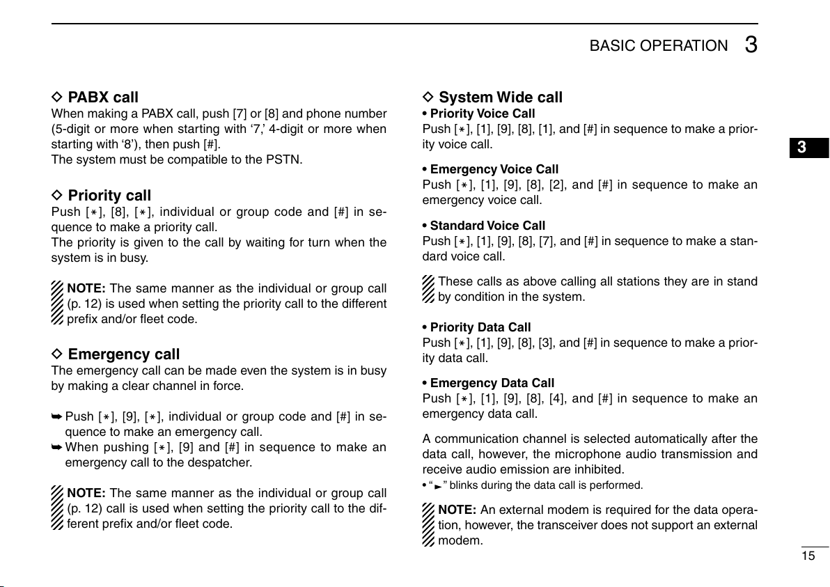
D PABX call
When making a PABX call, push [7] or [8] and phone number
(5-digit or more when starting with ‘7,’ 4-digit or more when
starting with ‘8’), then push [#].
The system must be compatible to the PSTN.
D Priority call
Push [
M], [8], [M], individual or group code and [#] in se-
quence to make a priority call.
The priority is given to the call by waiting for turn when the
system is in busy.
NOTE: The same manner as the individual or group call
(p. 12) is used when setting the priority call to the different
prefix and/or fleet code.
D Emergency call
The emergency call can be made even the system is in busy
by making a clear channel in force.
➥
➥ When pushing [
M], [9], [M], individual or group code and [#] in se-
Push [
quence to make an emergency call.
M], [9] and [#] in sequence to make an
emergency call to the despatcher.
NOTE: The same manner as the individual or group call
(p. 12) call is used when setting the priority call to the dif
ferent prefix and/or fleet code.
D System Wide call
• Priority Voice Call
Push [
M], [1], [9], [8], [1], and [#] in sequence to make a prior-
ity voice call.
• Emergency Voice Call
M], [1], [9], [8], [2], and [#] in sequence to make an
Push [
emergency voice call.
• Standard Voice Call
Push [
M], [1], [9], [8], [7], and [#] in sequence to make a stan-
dard voice call.
These calls as above calling all stations they are in stand
by condition in the system.
• Priority Data Call
M], [1], [9], [8], [3], and [#] in sequence to make a prior-
Push [
ity data call.
• Emergency Data Call
Push [
M], [1], [9], [8], [4], and [#] in sequence to make an
emergency data call.
A communication channel is selected automatically after the
data call, however, the microphone audio transmission and
receive audio emission are inhibited.
• “ ” blinks during the data call is performed.
-
NOTE: An external modem is required for the data opera-
tion, however, the transceiver does not support an external
modem.
1
2
3
4
5
6
7
8
9
10
11
12
13
14
15
16
15

BASIC OPERATION
3
D Include call
The include call allows to make an extra call for joining an-
other station for the communication after move to a commu
nication channel.
The include call is made when an individual or group code
selection using a memory or keypad is performed on the
communication channel.
D 5-digit routing code call
The 5-digit routing code call provides a shortening a calling
code input.
When calling a station that has a different prefix and/or fleet
code, the 3-digit prefix and 4-digit fleet code are converted
into 2 or 3-digit code, therefore, entering a total of 5-digit
code including an individual or group code.
• The conversion range
Code within 200 to 299, 900 to 998, 20 to 29 and 90 to 99
can be converted, and set the desired prefix and fleet code
must be registered in advance.
e.g.: When the station ‘200 2001 200’ calls the station ‘211
2006 300’;
➥Register the both prefix ‘211’ and fleet ‘2006’ to “22”
as the 5-digit routing code— Enter “22300” and push
ing [#] to make a 5-digit routing code call.
D Call cancel
M] and [#] to cancel the call.
Push [
The communication is disconnected, and the call is can
-
celled.
D Cancelling the entered code
During code entering from the keypad, pushing [Up]/[Down]
or [Backspace] to clear the previously entered digit code.
The entered all digit code can be cancelled by pushing
[Clear].
D Manual call reply
When the call with “ALERTING” indication is received, push
[#] or [PTT] to reply the call manually (off-hook).
D End of the communication
M] and [#], or push [Clear] to finish (disconnect) the
Push [
communication (on-hook).
-
-
16

BASIC OPERATION
3
■ Special call with the keypad
D Re-dial
Push [#] twice to re-call the previously called individual or
group station(s).
D Short dialing
Push one of [1] to [9] and [#], to make a call with the stored
individual or group code in the memory 1 to 9.
■ Receiving a call
D Receiving an individual call
q When an individual call is received, calling ring sounds.
• “ALERTING” and the calling station code (or text name if the
calling code is memorized in the memory) are displayed alter-
nately.
⇔
• When the call from a telephone, “TEL” (PSTN) or “PABX” is dis-
w Push [PTT] or [#] to start the communication.
• The communication timer is displayed and starts count down.
• The channel number and the communication timer are displayed
e The warning beeps sound 10 sec. before the communica-
• The communication is disconnected automatically when the
r Push [Clear] to disconnect the communication manually.
• Pushing [M] and [#] in sequence also disconnect the communi-
• The transceiver returns to stand-by condition.
ALERTING 302
played.
TEL PABX
(When no transmission time limit is set, the timer counts up.)
simultaneously (illustrated as at below right) when the communi-
cation channel number indication is set to ON. (p. 27)
TIM 0 56 0020 0 56
tion timer is activated.
communication timer is activated.
cation. (10-key version only)
1
2
3
4
5
6
7
8
9
10
11
12
13
14
15
16
17
BASIC OPERATION
3
• When not answering the call
When not answering call with [PTT], the calling station code
is stored into call back memory. (max. 15 channels)
• “
” blinks when a call from the station that the station code
does not stored in the call back memory, is received.
• “
” appears when the call back memory that call back op-
eration has not been performed is/are stored.
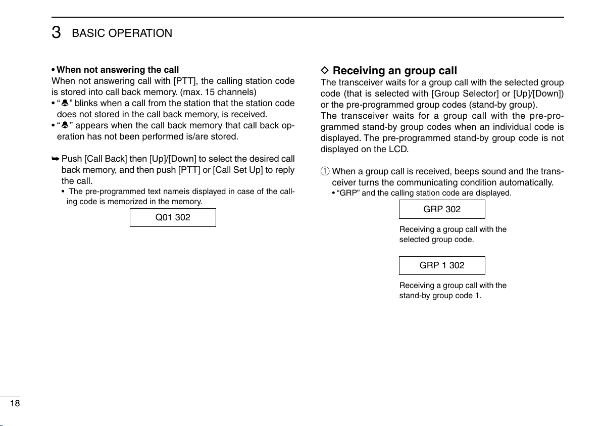
➥ Push [Call Back] then [Up]/[Down] to select the desired call
back memory, and then push [PTT] or [Call Set Up] to reply
the call.
• The pre-programmed text name is displayed in case of the call-
ing code is memorized in the memory.
Q01 302
D Receiving an group call
The transceiver waits for a group call with the selected group
code (that is selected with [Group Selector] or [Up]/[Down])
or the pre-programmed group codes (stand-by group).
The transceiver waits for a group call with the pre-pro
grammed stand-by group codes when an individual code is
displayed. The pre-programmed stand-by group code is not
displayed on the LCD.
q When a group call is received, beeps sound and the trans-
ceiver turns the communicating condition automatically.
• “GRP” and the calling station code are displayed.
GRP 302
Receiving a group call with the
selected group code.
GRP 1 302
Receiving a group call with the
stand-by group code 1.
-
18

BASIC OPERATION
3
w Push and hold [PTT] to communicate with the calling sta-
tion.
• The communication timer is displayed and starts count down.
(When no transmission time limit is set, the timer counts up.)
• The channel number and the communication timer are displayed
simultaneously (illustrated as at below right) when the communi-
cation channel number indication is set to ON. (p. 27)
e The warning beeps sound 10 sec. before the communica-
tion timer is activated.
• The communication is disconnected automatically when the
r Push [Clear] to disconnect the communication manually.
• Pushing [M] and [#] in sequence also disconnect the communi-
• The transceiver returns to stand-by condition.
TIM 0 56 0020 0 56
communication timer is activated.
cation. (10-key version only)
D Receiving a status message
When a status call is received, the transceiver emits beeps,
and the appropriate text message to the received status num
ber and the individual code of calling station are displayed
alternately.
• The display is cancelled and returns to the stand-by indica
tion when [Clear] is pushed.
• When the status 0 (call back request) is received, the calling
station code is stored into the call back memory and “
blinks. However, the status 31 (call back cancel) is received,
the calling station code is erased from the call back mem
ory.
STATUS 1 302
⇔
D Receiving an SDM (Short Data Message)
When an SDM is received, beeps sound and the received
message contents and the calling station code are displayed
alternately.
• “
9-digit message is received.
- Push [Down] to scroll the indication to display the following
- Push [Up] to display the previous digit message.
- Push [Clear] to return to stand-by indication.
(Message) 302
” appears when the message that containing more than
message in this case.
⇔
1
-
2
3
4
5
-
6
7
”
-
8
9
10
11
12
13
14
15
16
19
BASIC OPERATION
3
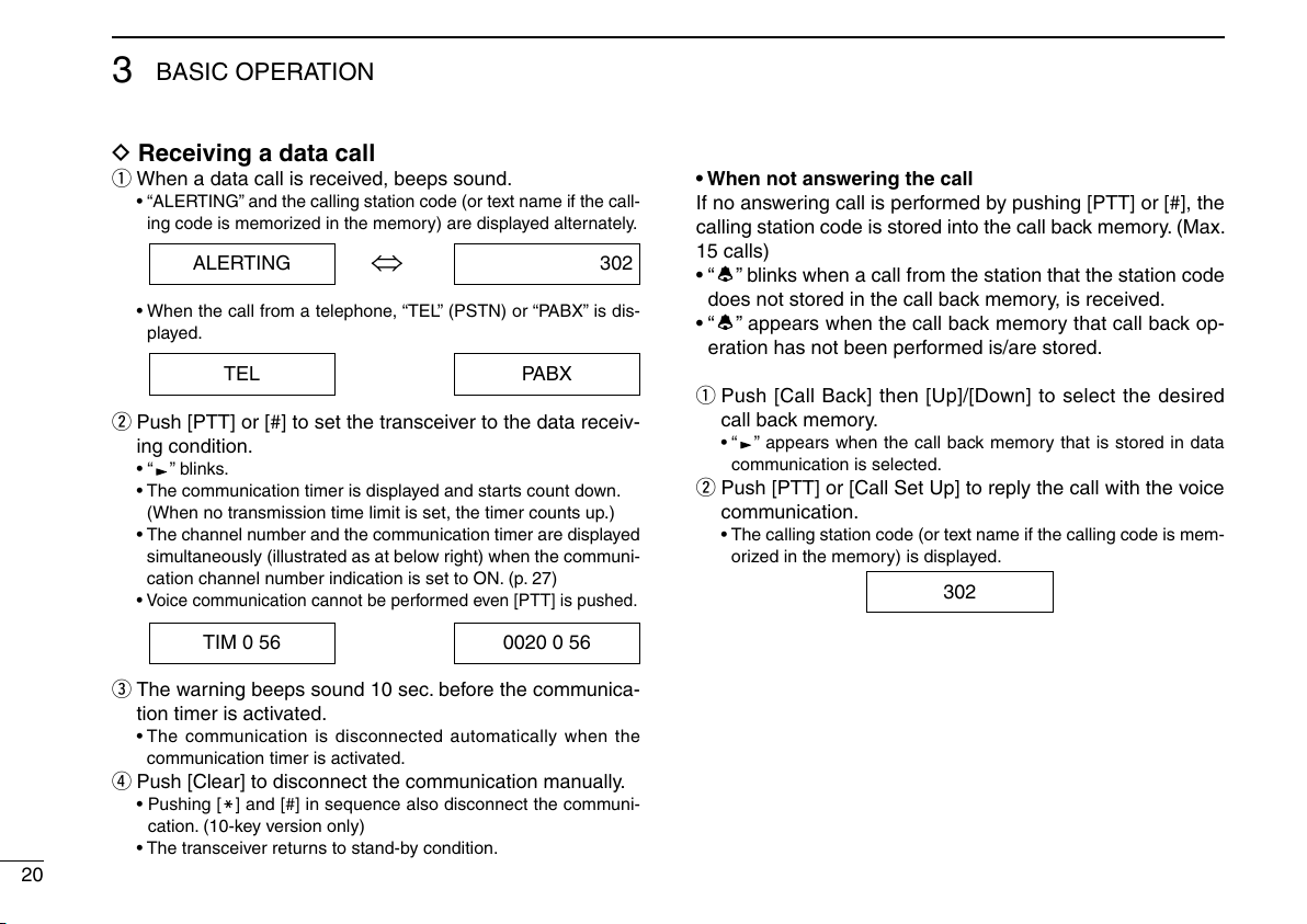
D Receiving a data call
q When a data call is received, beeps sound.
• “ALERTING” and the calling station code (or text name if the call-
ing code is memorized in the memory) are displayed alternately.
⇔
• When the call from a telephone, “TEL” (PSTN) or “PABX” is dis-
w Push [PTT] or [#] to set the transceiver to the data receiv-
• “ ” blinks.
• The communication timer is displayed and starts count down.
• The channel number and the communication timer are displayed
• Voice communication cannot be performed even [PTT] is pushed.
ALERTING 302
played.
TEL PABX
ing condition.
(When no transmission time limit is set, the timer counts up.)
simultaneously (illustrated as at below right) when the communi-
cation channel number indication is set to ON. (p. 27)
• When not answering the call
If no answering call is performed by pushing [PTT] or [#], the
calling station code is stored into the call back memory. (Max.
15 calls)
• “
” blinks when a call from the station that the station code
does not stored in the call back memory, is received.
• “
” appears when the call back memory that call back op-
eration has not been performed is/are stored.
q Push [Call Back] then [Up]/[Down] to select the desired
call back memory.
• “ ” appears when the call back memory that is stored in data
communication is selected.
w Push [PTT] or [Call Set Up] to reply the call with the voice
communication.
• The calling station code (or text name if the calling code is mem-
orized in the memory) is displayed.
302
20
TIM 0 56 0020 0 56
e The warning beeps sound 10 sec. before the communica-
tion timer is activated.
• The communication is disconnected automatically when the
communication timer is activated.
r Push [Clear] to disconnect the communication manually.
• Pushing [M] and [#] in sequence also disconnect the communi-
cation. (10-key version only)
• The transceiver returns to stand-by condition.
ABORTED
ALERTING
AUTO
CALLBACK
CALLING
CANCELL
Ch
CLR DOWN
CONNECT
DESPATCH
DIVERTED
DYN GRP
EMRGENCY
ENGAGED
FAILED
GRP
INTER--FL
Indication Description
Aborted: The call has been aborted. Re-call later.
Alerting
Auto (RF Power):
Call Back:
Calling the station.
Canceled: The call/input has been canceled.
Ch##: Channel number ## (Conventional mode)
Clear Down: The communication connection is disconnected.
Connected: The call is succeeded. Communication can be made.
Despatcher: The despatcher number is selected.
Diverted: The call is transferred to another station.
Dynamic Group: A new group number is set.
Emergency: [Emergency] is pushed and held.
Engaged: The calling station is in busy. Re-call later.
Failed:
Group##: Stand-by group code ##
Inter Fleet: The call is received from the different fleet.
The automatic transmit output power
selection is set.
The call is recorded at the calling station.
Wait for the reply.
The call is failed. Or, the system does not support
the calling number.
Indication
INVALID
LOW
LOW BATT
NO REPLY
OK
OVERVOLT
PABX
PASSWORD
Q
QUEUED
RINGING
SYS BUSY
SYS WIDE
TEL
TIMEOUT
TIM
Description
Invalid: The calling number is wrong.
Low#: The low transmit output power # is set.
Low Battery:
No Reply: No reply is received with the call.
OK: The call is succeeded.
Over Voltage:
PABX: Receiving a call from PABX.
Password: Enter the password.
Queue##: Call back memory number ##.
Queued: The call is waiting for turn. Wait for a while.
Ringing: Ringing the calling bell sound at the calling station.
System Busy:
System Wide: Receiving a system wide call.
Telephone: Receiving a call from PSTN.
Timeout: The communication timer has been over.
Timer ##:##: The communicating timer indication.
The battery is exhausted and the transceiver power is
turned OFF automatically.
The supplied voltage exceeds the specified input
voltage range.
The system unable to receive a call because of
the system in busy. Re-call later.
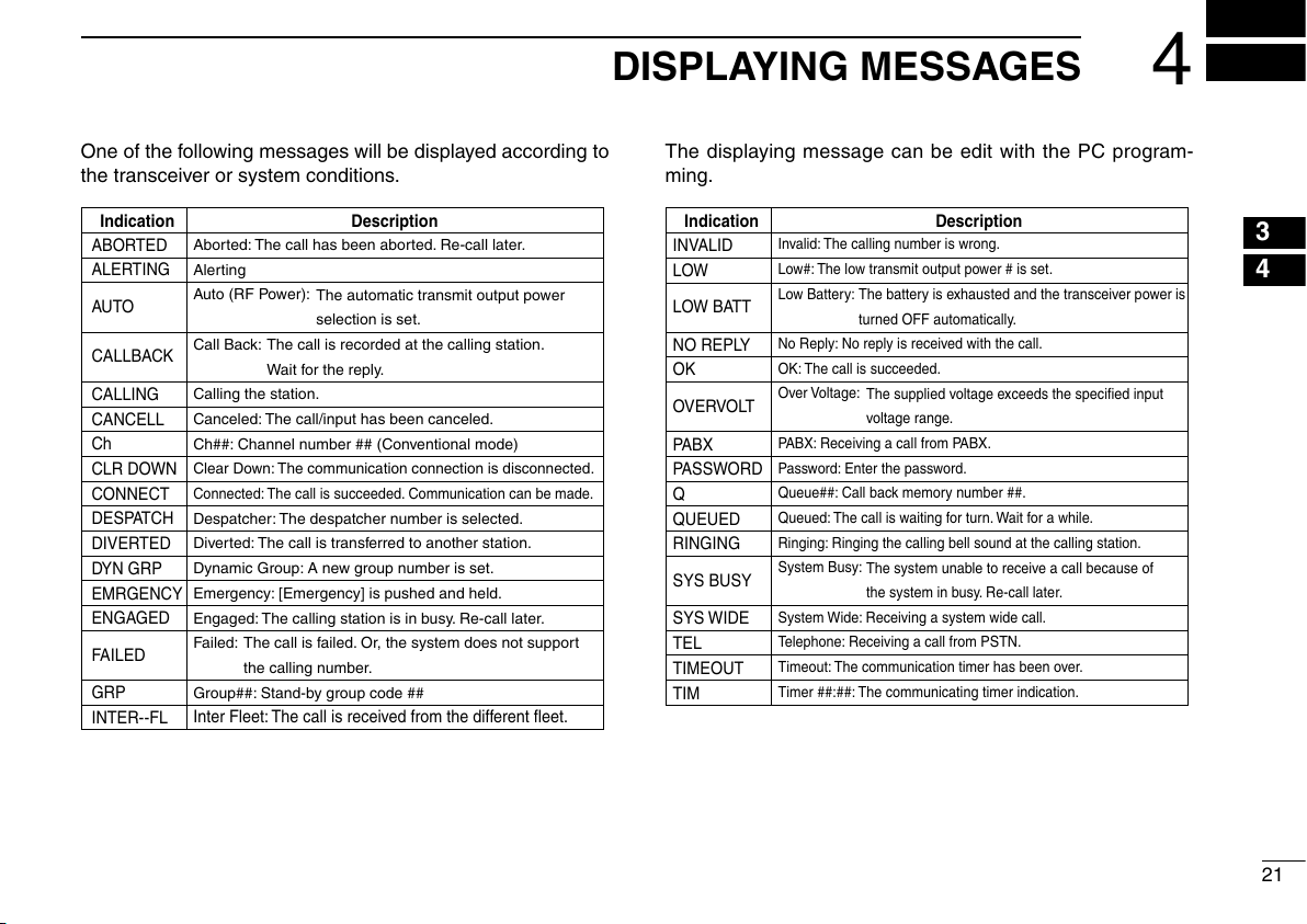
DISPLAYING MESSAGES
4
One of the following messages will be displayed according to
the transceiver or system conditions.
The displaying message can be edit with the PC program-
ming.
1
2
3
4
5
6
7
8
9
10
11
12
13
14
15
16
21
5
OTHER FUNCTIONS
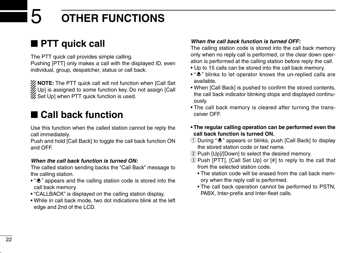
■ PTT quick call
The PTT quick call provides simple calling.
Pushing [PTT] only makes a call with the displayed ID, even
individual, group, despatcher, status or call back.
NOTE: The PTT quick call will not function when [Call Set
Up] is assigned to some function key. Do not assign [Call
Set Up] when PTT quick function is used.
■ Call back function
Use this function when the called station cannot be reply the
call immediately.
Push and hold [Call Back] to toggle the call back function ON
and OFF.
When the call back function is turned ON:
The called station sending backs the “Call Back” message to
the calling station.
• “
” appears and the calling station code is stored into the
call back memory.
• “CALLBACK” is displayed on the calling station display.
• While in call back mode, two dot indications blink at the left
edge and 2nd of the LCD.
When the call back function is turned OFF:
The calling station code is stored into the call back memory
only when no reply call is performed, or the clear down oper
ation is performed at the calling station before reply the call.
• Up to 15 calls can be stored into the call back memory.
• “
” blinks to let operator knows the un-replied calls are
available.
• When [Call Back] is pushed to confirm the stored contents,
the call back indicator blinking stops and displayed continu
ously.
• The call back memory is cleared after turning the trans
ceiver OFF.
• The regular calling operation can be performed even the
call back function is turned ON.
q During “
the stored station code or text name.
w Push [Up]/[Down] to select the desired memory.
e Push [PTT], [Call Set Up] or [#] to reply to the call that
from the selected station code.
• The station code will be erased from the call back mem
ory when the reply call is performed.
• The call back operation cannot be performed to PSTN,
PABX, Inter-prefix and Inter-fleet calls.
” appears or blinks, push [Call Back] to display
-
-
-
-
22

OTHER FUNCTIONS
5
• Erasing the call back memory
q Push [Call Back] then select the desired call back memory
to be erased with [Up]/[Down].
w Push and hold [Call Back] for 2.5 sec. to erase the se-
lected call back memory.
• All the stored call back memory can be erased with the
same operation as above depending on the setting.
• When all of the 15 call back memories are stored and
16th call is received, the called station sent the message,
“Don’t Disturb” to the system repeater. In this case, the
message that the call has failed is displayed on the call
ing station display.
■ Calling station ID indication
for group call
The communicating station code can be displayed at any
time.
This function can be turned ON or OFF in advance.
The “Pressel signal” from the calling transceiver is used for
the indication, however, the “Pressel signal” is not through out
-
with some trunking system repeater. No station code indica
tion is provided in this case.
NOTE: This function may function differently or not func-
tion depending on the trunking system controller in place.
1
2
3
4
5
6
-
7
8
9
10
11
12
13
14
15
16
23
OTHER FUNCTIONS
5
■ System lock function
The system lock function disables the roaming function man-
ually.
q Push [M], [5], [1] and [#] in sequence to turn the system
lock function ON.
• The dot indication appears at right edge of the LCD.
w Push [#], [5], [1] and [#] in sequence to turn the system
lock function OFF.
• The dot indication disappears.
■ Call code memory
Up to 4 codes, individual, group or status, can be pro-
grammed from the keypad.
The programmed codes can be selected with [Up]/[Down].
➥ Push [M], [6], [0], [M], [x]*, [M], [code number] and [#] in
sequence to program the desired code into the memory.
• No erasing capability is available, over-write the new code in
such a case.
*x=1 to 4
■ Automatic transmit output
power selection
(Except for the conventional operation)
During trunking operation, the transmit output power is au
tomatically selected from High, Low2 and Low1 according to
the received signal strength from the system base.
■ Power ON security
The transceiver has a power ON security that requires the
4-digit password entry at turning the power ON.
The transceiver cannot be used until the correct password is
entered.
-
24

OTHER FUNCTIONS
5
■ Voice scrambler
The optional voice scrambler, UT-109 and UT-110, are avail-
able.
The scrambler will be turned ON when the desired scrambler
code is selected in user set menu. (p. 26)
• Use the UT-109 with the trunking operation is recommended.
• The transceiver has built-in voice scrambler (inversion type).
NOTE:
• The UT-110 (with rolling setting)
the trunking operation, because of the rolling synchroni
zation will be shifted by the interval transmission for the
system.
• Both the UT-109 and UT-110 are usable for conventional
operation.
• The built-in voice scrambler does not have a compatibil
ity with the UT-109 and UT-110.
CANNOT be used with
■ DTMF operation
While pushing and holding [PTT], push a key ([0] to [9], [P0]
to [P3]*, [
The transceiver should be in the condition that the communi
cation is enabled with [PTT] on a traffic channel.
*[P0] to [P3] correspond to the DTMF tone A to D, respectively.
M] and [#]) to output the appropriate DTMF tone.
■ Compander function
When the compander function is set to ON, the communicat-
ing audio quality will be increased.
The compander function can be turned ON or OFF in user
set menu. (p. 26)
-
-
-
1
2
3
4
5
6
7
8
9
10
11
12
13
14
15
16
25
6
USER SET MENU
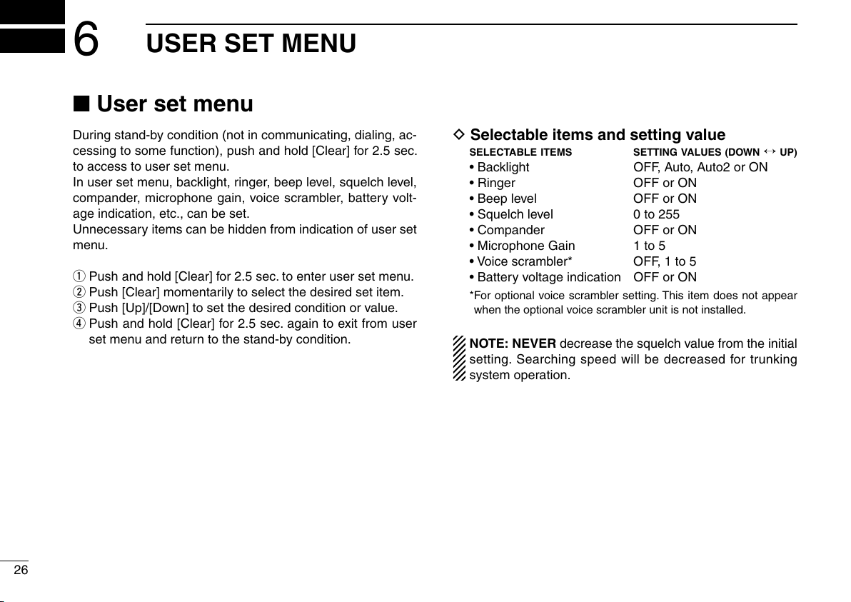
■ User set menu
During stand-by condition (not in communicating, dialing, ac-
cessing to some function), push and hold [Clear] for 2.5 sec.
to access to user set menu.
In user set menu, backlight, ringer, beep level, squelch level,
compander, microphone gain, voice scrambler, battery volt
age indication, etc., can be set.
Unnecessary items can be hidden from indication of user set
menu.
q Push and hold [Clear] for 2.5 sec. to enter user set menu.
w Push [Clear] momentarily to select the desired set item.
e Push [Up]/[Down] to set the desired condition or value.
r Push and hold [Clear] for 2.5 sec. again to exit from user
set menu and return to the stand-by condition.
D Selectable items and setting value
SELECTABLE ITEMS
• Backlight OFF, Auto, Auto2 or ON
• Ringer OFF or ON
-
• Beep level OFF or ON
• Squelch level 0 to 255
• Compander OFF or ON
• Microphone Gain 1 to 5
• Voice scrambler* OFF, 1 to 5
• Battery voltage indication OFF or ON
* For optional voice scrambler setting. This item does not appear
when the optional voice scrambler unit is not installed.
NOTE: NEVER decrease the squelch value from the initial
setting. Searching speed will be decreased for trunking
system operation.
SETTING VALUES (DOWN ↔ UP)
26

• Channel number indication
When the system information indication is enabled, the op
erating channel number is displayed with the communication
timer.
0014 0 59
USER SET MENU
6
1
2
3
-
4
5
6
“Enable”
Channel number and timer indication
TIM 0 59
“Disable”
Timer indication
D CPU revision indication
While pushing and holding [P3] and [Up], turn the transceiver
power ON to indicate the following information.
• CPU revision number and check some
• ESN number
• Clone comment (1) and (2)
• Installed optional unit name (if installed)
7
8
9
10
11
12
13
14
15
16
27

7
The transceiver has a conventional operation capability also
for when the transceiver is in out-of service area.
The tone squelch operation with CTCSS is available for the
conventional operation, as well as the ANI (Automatic Num
bering Identification) transmission at PTT ON and/or OFF.
NOTE: The pressel signal of trunking is used for the ANI
operation.
➥ By pushing [Monitor], both the tone and noise squelch is
released to monitor the selected channel conditions.
➥ Total of 32 conventional channels are available and are se-
lectable with [Up]/[Down].
The conventional channels must be programmed in ad
vance.
• Switching with the automatic talk around
The conventional mode will be selected automatically when
the trunking control channel is fall down or the transceiver
move into the out-of service area.
Even the conventional mode is selected, the transceiver
automatically searching for a usable control channel by re
turning into trunking mode in interval. Then the transceiver is
switched to trunking mode when a usable control channel is
found, or return to conventional mode when no usable control
channel is found.
The automatic talk around is disabled by setting “OFF” in au
tomatic talk around timer with the programming.
TALK AROUND
•
Switching with [Mode], or [P1] and [Up] operation at
power ON.
Push [Mode] to toggle the operation mode between trunking
and conventional mode.
-
Or, while pushing and holding both [P1] and [Up], turn the
transceiver power ON to toggle the operation mode between
trunking and conventional mode.
Once the operation mode is selected with either opera
tion, the operation mode won’t be changed until [Mode] is
pushed.
Even the transceiver is turned OFF, the transceiver remains
the operation mode.
-
-
-
NOTE: [Mode] must be assigned in key assignment for
both trunking and conventional if manual operation mode
selection is required.
-
28
PROGRAMMABLE FUNCTIONS
8
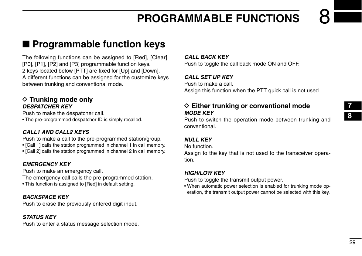
■ Programmable function keys
The following functions can be assigned to [Red], [Clear],
[P0], [P1], [P2] and [P3] programmable function keys.
2 keys located below [PTT] are fixed for [Up] and [Down].
A different functions can be assigned for the customize keys
between trunking and conventional mode.
D Trunking mode only
DESPATCHER KEY
Push to make the despatcher call.
• The pre-programmed despatcher ID is simply recalled.
CALL1 AND CALL2 KEYS
Push to make a call to the pre-programmed station/group.
• [Call 1] calls the station programmed in channel 1 in call memory.
• [Call 2] calls the station programmed in channel 2 in call memory.
EMERGENCY KEY
Push to make an emergency call.
The emergency call calls the pre-programmed station.
• This function is assigned to [Red] in default setting.
BACKSPACE KEY
Push to erase the previously entered digit input.
STATUS KEY
Push to enter a status message selection mode.
CALL BACK KEY
Push to toggle the call back mode ON and OFF.
CALL SET UP KEY
Push to make a call.
Assign this function when the PTT quick call is not used.
D Either trunking or conventional mode
MODE KEY
Push to switch the operation mode between trunking and
conventional.
NULL KEY
No function.
Assign to the key that is not used to the transceiver opera
tion.
HIGH/LOW KEY
Push to toggle the transmit output power.
• When automatic power selection is enabled for trunking mode op-
eration, the transmit output power cannot be selected with this key.
1
2
3
4
5
6
7
8
9
10
11
-
12
13
14
15
16
29

PROGRAMMABLE FUNCTIONS
8
UP AND DOWN KEYS
➥Push to select the call memory channel.
➥Push to select the call back memory channel.
➥Push to select the status channel.
➥ Push to select the operating channel. (Conventional mode
operation only)
➥ Push to select the setting value or condition during user
set mode.
➥ Push to erase the previously entered digit number (func-
tions as back space key) during dialing number entering
from the keypad. (10-key version only)
LOCK KEY
Push to inhibit the function key operations, except [PTT] and
[Lock].
CLEAR (SET MODE) KEY
➥Push to disconnect the communication (clear down).
➥Push and hold for 2.5 sec. to enter user set menu.
D Conventional mode only
MONITOR KEY
Push to release both the tone and noise squelch mute at the
same time to monitor the signal on the selected operating
channel.
SIMPLEX KEY
The both receive frequency and receive CTCSS frequency
are used as the transmit frequency and transmit CTCSS fre
quency, respectively.
Direct communication without a repeater can be made.
-
30

*This illustration is
described with
the UT-109.
OPTIONAL UNIT INSTALLATION
9
■ UT-109 and UT-110 installation
Install the optional unit as follows:
q Rotate [VOL] to turn the power OFF, and remove the bat-
tery pack. (p. 2)
w Remove the unit cover.
NOTE: Insert a standard screw driver into the hollow of the chas-
sis, then lift and take away the unit cover illustrated as below.
Use the supplied spare unit cover! Do not use the cover that
has been removed once. Water or dust may get into the trans-
ceiver because the cover may be bent or has lost it’s adhesion.
This may result in the transceiver being damaged.
e Cut the pattern on the PCB at the TX mic circuit (MIC) and
RX AF circuit (DISC) as shown below.
r Install the unit as shown below.
t Replace the unit cover and the battery pack, then rotate
[VOL] to turn the power ON.
NOTE: When uninstalling the scrambler unit
Be sure to re-solder the disconnected points at left, other
wise no TX modulation or AF output is available.
1
2
3
4
5
6
7
8
9
10
-
11
12
13
14
15
16
31
10
BATTERY CHARGING
■ Caution
Misuse of Lithium-Ion batteries may result in the fol-
lowing hazards: smoke, fire, or the battery may rupture.
Misuse can also cause damage to the battery or degra
dation of battery performance.
R DANGER! Use and charge only specified Icom battery
packs with Icom radios or Icom chargers. Only Icom battery
packs are tested and approved for use and charge with Icom
radios or Icom chargers. Using third-party or counterfeit bat
tery packs or chargers may cause smoke, fire, or cause the
battery to burst.
-
D Battery caution
R DANGER! DO NOT hammer or otherwise impact the bat-
tery. Do not use the battery if it has been severely impacted
or dropped, or if the battery has been subjected to heavy
pressure. Battery damage may not be visible on the outside
of the case. Even if the surface of the battery does not show
cracks or any other damage, the cells inside the battery may
rupture or catch fire.
R DANGER! NEVER use or leave battery packs in areas
with temperatures above +60˚C. High temperature buildup in
the battery, such as could occur near fires or stoves, inside
a sun heated car, or in direct sunlight may cause the battery
to rupture or catch fire. Excessive temperatures may also de
grade battery performance or shorten battery life.
R DANGER! DO NOT expose the battery to rain, snow,
seawater, or any other liquids. Do not charge or use a wet
battery. If the battery gets wet, be sure to wipe it dry before
using. The battery is not waterproof.
-
R DANGER! NEVER incinerate used battery packs since in-
ternal battery gas may cause them to rupture, or may cause
an explosion.
R DANGER! NEVER solder the battery terminals or NEVER
modify the battery pack. This may cause heat generation, and
the battery may rupture, emit smoke or catch fire.
R DANGER! Use the battery only with the transceiver for
which it is specified. Never use a battery with any other equip
ment, or for any purpose that is not specified in this instruc
tion manual.
R DANGER! If fluid from inside the battery gets in your eyes,
blindness can result. Rinse your eyes with clean water, with
out rubbing them, and see a doctor immediately.
-
-
-
-
32
BATTERY CHARGING
10
1
WARNING! Immediately stop using the battery if it emits an
abnormal odor, heats up, or is discolored or deformed. If any
of these conditions occur, contact your Icom dealer or dis
tributor.
WARNING! Immediately wash, using clean water, any part
of the body that comes into contact with fluid from inside the
battery.
WARNING! NEVER put the battery in a microwave oven,
high-pressure container, or in an induction heating cooker.
This could cause a fire, overheating, or cause the battery to
rupture.
CAUTION! Always use the battery within the specified tem-
perature range for the transceiver (–25˚C to +55˚C) and the
battery itself (–20˚C to +60˚C). Using the battery out of its
specified temperature range will reduce the battery’s perfor
mance and battery life. Please note that the specified temper
ature range of the battery may exceed that of the transceiver.
In such cases, the transceiver may not work properly because
it is out of its operating temperature range.
CAUTION! Shorter battery life could occur if the battery is left
fully charged, completely discharged, or in an excessive tem
perature environment (above +45˚C) for an extended period
of time. If the battery must be left unused for a long time, it
must be detached from the radio after discharging. You may
use the battery until the battery indicator shows half-capacity,
then keep it safely in a cool dry place with the temperature
between –20˚C to +25˚C.
D Charging caution
R DANGER! NEVER charge the battery pack in areas with
extremely high temperatures, such as near fires or stoves,
-
inside a sun heated car, or in direct sunlight. In such environ
ments, the safety/protection circuit in the battery will activate,
causing the battery to stop charging.
WARNING! DO NOT charge or leave the battery in the bat-
tery charger beyond the specified time for charging. If the
battery is not completely charged by the specified time, stop
charging and remove the battery from the battery charger.
Continuing to charge the battery beyond the specified time
limit may cause a fire, overheating, or the battery may rup
ture.
WARNING! NEVER insert the transceiver (battery attached
to the transceiver) into the charger if it is wet or soiled. This
-
could corrode the battery charger terminals or damage the
-
charger. The charger is not waterproof.
CAUTION! DO NOT charge the battery outside of the speci-
fied temperature range: BC-160 (0˚C to +45˚C). Icom recom-
mends charging the battery at +20˚C. The battery may heat
up or rupture if charged out of the specified temperature
-
range. Additionally, battery performance or battery life may
be reduced.
2
3
-
4
5
6
7
8
9
-
10
11
12
13
14
15
16
33

BATTERY CHARGING
AC adapter
(Not supplied with
some versions.)
Optional OPC-515L
(for 13.8 V power
source) or CP-17L
(for 12 V cigarette
lighter socket) can
be used instead of
the AC adapter.
BATTERY
PACK
TRANSCEIVER
Turn power OFF
Screws supplied
with the charger
adapter
AD-106
Connectors
Plugs
10
■ Optional battery chargers
D Rapid charging with the BC-160
The optional BC-160 provides rapid charging of optional Li-
Ion battery packs.
• An AC adapter (may be supplied with BC-160 depending
on version) or the DC power cable (OPC-515L/CP-17L) is
additionally required.
D AD-106 installation
The AD-106 CHARGER ADAPTER must be installed into the
BC-119N or BC-121N before battery charging.
➥
Connect the AD-106
BC-121N as below, then install the AD-106 into the holder
space of the BC-119N or BC-121N with the supplied
screws.
CHARGER ADAPTER and the BC-119N/
34

AD-106 charger
adapter is installed
in BC-119N.
AC adapter
(Not supplied with
some versions.)
Optional OPC-515L (for 13.8 V
power source) or CP-17L (for 12
V cigarette lighter socket) can be
used instead of the AC adapter.
TRANSCEIVER
BATTERY
PACK
Turn power OFF
AC adapter
(Purchase
separately)
AD-106 charger
adapters are installed
in each slot.
DC power cable (OPC-656)
(Connect with the DC power supply;
13.8 V/at least 7 A)
TRANSCEIVER
BATTERY
PACK
Turn power OFF
BATTERY CHARGING
10
D Rapid charging with the BC-119N+AD-106
The optional BC-119N provides rapid charging of battery
packs. The following items are additionally required.
• AD-106 charger adapter
• An AC adapter (may be supplied with BC-119N depending
on version) or the DC power cable (OPC-515L/CP-17L).
D Rapid charging with the BC-121N+AD-106
The optional BC-121N allows up to 6 battery packs to be
charged simultaneously. The following items are additionally
required.
• Six AD-106 charger adapters
• An AC adapter (BC-157) or the DC power cable (OPC-656)
1
2
3
4
5
6
7
8
9
10
11
12
13
14
15
16
35

BATTERY CHARGING
Guide rail
Lobs
10
IMPORTANT!: Battery charging
Ensure the guide lobs on the battery pack are correctly
aligned with the guide rails inside the charger adapter.
(This illustration is described with the BC-160.)
36

q
BP-240
w
Fig.1
Fig.2
Fig.3
e
r
t
OPTIONAL BATTERY CASE
11
■ Battery case (BP-240)
When using the optional battery case, install 6 × AAA (LR03)
size alkaline batteries as illustrated at right.
q Unhook the battery cover release hook (q), and open the
cover in the direction of the arrow (
w Then, install 6 × AAA (LR03) size alkaline batteries.
(Fig.2)
• Install the alkaline batteries only.
• Be sure to observe the correct polarity.
• Do not place the ribbon over the batteries.
e Fit the cover in the direction of the arrow (e), then close
(r). And hook the batter y cover release hook until it
makes a ‘click’ sound (
CAUTION:
• When installing batteries, make sure they are all the
same brand, type and capacity. Also, do not mix new and
old batteries together.
• Keep battery contacts clean. It’s a good idea to clean bat
tery terminals once a week.
• Never incinerate used battery cells since internal battery
gas may cause them to rupture.
•
Never expose a detached battery case to water. If the bat-
tery case gets wet, be sure to wipe it dry before using it.
t). (Fig.3)
w). (Fig.1)
1
2
3
4
5
6
7
8
9
10
11
12
-
13
14
15
16
37
12
q w
OPTIONAL SWIVEL BELT CLIP
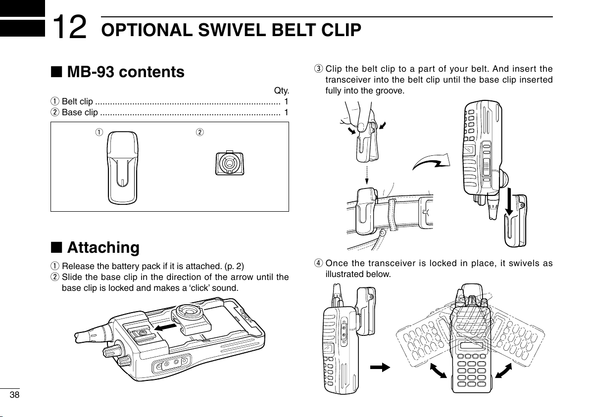
■ MB-93 contents
Qty.
q Belt clip ........................................................................... 1
w Base clip ......................................................................... 1
■ Attaching
q Release the battery pack if it is attached. (p. 2)
w Slide the base clip in the direction of the arrow until the
base clip is locked and makes a ‘click’ sound.
e Clip the belt clip to a par t of your belt. And insert the
transceiver into the belt clip until the base clip inserted
fully into the groove.
r Once the transceiver is locked in place, it swivels as
illustrated below.
38

q
w
OPTIONAL SWIVEL BELT CLIP
12
■ Detaching
q Turn the transceiver upside down in the direction of the
arrow and pull out from the belt clip.
w Release the battery pack if it is attached. (p. 2)
e Pinch the clip (q), and slide the base clip in the direction
of the arrow (w).
CAUTION:
HOLD THE TRANSCEIVER TIGHTLY, WHEN HANGING
OR DETACHING THE TRANSCEIVER FROM THE BELT
CLIP.
Otherwise the transceiver may not be attached to the
holder or swivel properly if the transceiver is accidentally
dropped and the base clip is scratched or damaged.
1
2
3
4
5
6
7
8
9
10
11
12
13
14
15
16
39

13
OPTIONS
40
D BATTERY PACKS
—*
1
2
Battery pack Voltage Capacity Battery life*
BP-230N 7.4 V
BP-232N 7.4 V
BP-240
1
*
When the power save function is turned ON, and the operating
periods are calculated under the following conditions;
TX : RX : standby = 5 : 5 : 90
2
*
Operating period depends on the alkaline cells used.
Battery case for AAA
950 mAh (min.)
980 mAh (typ.)
1900 mAh (min.)
2000 mAh (typ.)
(LR03) × 6 alkaline
6.50 hrs.
13.25 hrs.
D CHARGERS
• BC-119N DESKTOP CHARGER + AD-106 CHARGER ADAPTER
+ BC-145
For rapid charging of battery packs. An AC adapter is sup-
plied with the charger depending on versions. Charging
time: approx. 3 hours when BP-232N is attached.
• BC-121N
+ BC-157 AC ADAPTER
For rapid charging of up to 6 battery packs (six AD-106’
s are required) simultaneously. An AC adapter should be
purchased separately. Charging time: approx. 3 hours when
BP-232N is attached.
• BC-160
For rapid charging of battery packs. An AC adapter is sup-
plied with the charger depending on versions. Charging
time: approx. 3 hours when BP-232N is attached.
AC ADAPTER
MULTI-CHARGER + AD-106 CHARGER ADAPTER (6 pcs.)
DESKTOP CHARGER + BC-145 AC ADAPTER
D BELT CLIPS
• MB-93
• MB-94 BELT CLIP
Exclusive alligator-type belt clip. The same as supplied with
• MB-96N/96F
SWIVEL BELT CLIP
the transceiver.
LEATHER BELT HANGER
D OPTIONAL UNITS
• UT-109 (#02)/UT-110 (#02)
Non-rolling type (UT-109)/Rolling type (UT-110) voice
scrambler unit provides higher communication security.
SCRAMBLER UNITS
D DC CABLES
• CP-17L
Allows charging of the battery pack through a 12 V ciga-
rette lighter socket. (For BC-119N)
• OPC-515L/OPC-656
Allows charging of the battery pack using a 13.8 V power
source instead of the AC adapter.
OPC-515L: For BC-119N
OPC-656 : For BC-121N
CIGARETTE LIGHTER CABLE
DC POWER CABLES
OPTIONS
13
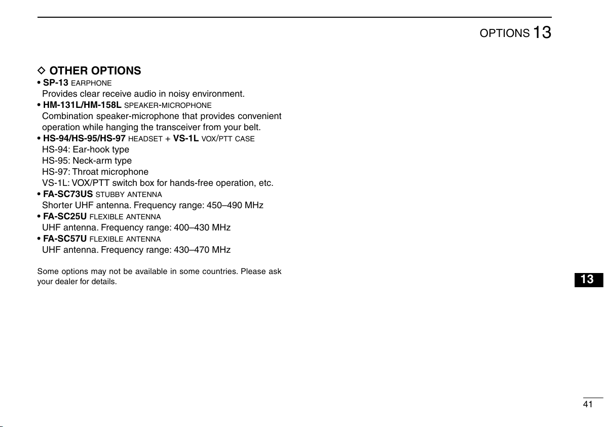
D OTHER OPTIONS
• SP-13
Provides clear receive audio in noisy environment.
• HM-131L/HM-158L SPEAKER-MICROPHONE
Combination speaker-microphone that provides convenient
• HS-94/HS-95/HS-97
HS-94: Ear-hook type
HS-95: Neck-arm type
HS-97: Throat microphone
VS-1L: VOX/PTT switch box for hands-free operation, etc.
• FA-SC73US
Shorter UHF antenna. Frequency range: 450–490 MHz
• FA-SC25U
UHF antenna. Frequency range: 400–430 MHz
• FA-SC57U FLEXIBLE ANTENNA
UHF antenna. Frequency range: 430–470 MHz
Some options may not be available in some countries. Please ask
your dealer for details.
EARPHONE
operation while hanging the transceiver from your belt.
HEADSET + VS-1L VOX/PTT CASE
STUBBY ANTENNA
FLEXIBLE ANTENNA
1
2
3
4
5
6
7
8
9
10
11
12
13
14
15
16
41
42
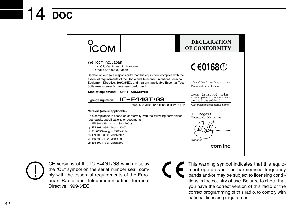
DECLARATION
OF CONFORMITY
We Icom Inc. Japan
1-1-32, Kamiminami, Hirano-ku
Osaka 547-0003, Japan
Kind of equipment:
UHF TRANSCEIVER
Type-designation: iC-
f44gt/gs
Signature
Authorized representative name
Place and date of issue
Declare on our sole responsibility that this equipment complies with the
essential requirements of the Radio and Telecommunications Terminal
Equipment Directive, 1999/5/EC, and that any applicable Essential Test
Suite measurements have been performed.
Version (where applicable):
This compliance is based on conformity with the following harmonised
standards, specifications or documents:
i) EN 301 489-1 v1.3.1 (Sept 2001)
ii) EN 301 489-5 (August 2000)
iii) EN 60950 (August 1992+A11)
iv) EN 300 086-2 (March 2001)
v) EN 300 219-2 (March 2001)
vi) EN 300 113-2 (March 2001)
400–470 MHz 12.5 kHz/20 kHz/25 kHz
0168
Düsseldorf
30th Apr. 2004
14
DOC
CE versions of the IC-F44GT/GS which display
the “CE” symbol on the serial number seal, com
ply with the essential requirements of the Euro
pean Radio and Telecommunication Terminal
Directive 1999/5/EC.
-
-
This warning symbol indicates that this equip-
ment operates in non-harmonised frequency
bands and/or may be subject to licensing condi
tions in the country of use. Be sure to check that
you have the correct version of this radio or the
correct programming of this radio, to comply with
national licensing requirement.
-

MEMO
1
2
3
4
5
6
7
8
9
10
11
12
13
14
15
16
43

< Intended Country of Use >
GER
AUT
GBR
IRL
NOR
FRA
NED
BEL
LUX
ESP
POR
ITA
GRE
SWE
DEN
FIN
SUI
A-6580H-1EU-w
Printed in Japan
© 2007–2009 Icom Inc.
Printed on recycled paper with soy ink.
1-1-32 Kamiminami, Hirano-ku, Osaka 547-0003, Japan
 Loading...