

Page 1

INSTRUCTION MANUAL
VHF TRANSCEIVER
iF3062T/S
UHF TRANSCEIVER
iF4062T/S
Page 2

IMPORTANT
PRECAUTIONS
READ ALL INSTRUCTIONS carefully and com-
pletely before using the transceiver.
SAVE THIS INSTRUCTION MANUAL— This
instruction manual contains important oper ating instructions
for the IC-F3062T and IC-F3062S VHF TRANSCEIVERS and
IC-F4062T and IC-F4062S UHF TRANSCEIVERS.
R DANGER! Use and charge only specified Icom battery
packs with Icom radios or Icom chargers. Only Icom battery
packs are tested and approved for use with Icom radios or
charged with Icom chargers. Using third-party or counterfeit
battery packs or chargers may cause smoke, fire, or cause
the battery to burst.
R WARNING! NEVER hold the radio so that the an-
tenna is very close to, or touching exposed parts of the body,
EXPLICIT DEFINITIONS
WORD DEFINITION
RDANGER!
RWARNING!
CAUTION
NOTE
Icom, Icom Inc. and the Icom logo are registered trademarks of Icom
Incorporated (Japan) in Japan, the United States, the United Kingdom, Germany, France, Spain, Russia and/or other countries.
i
Personal death, serious injury or an explosion may occur.
Personal injury, fire hazard or electric
shock may occur.
Equipment damage may occur.
If disregarded, inconvenience only. No risk
of personal injury, fire or electric shock.
especially the face or eyes, while transmitting. The radio will
perform best if the microphone is 5 to 10 cm away from the
lips and the radio is vertical.
R WARNING! NEVER operate the radio with a headset
or other audio accessories at high volume levels. The continuous high volume operation may cause a ringing in your
ears. If you experience the ringing, reduce the volume level
or discontinue use.
R WARNING! NEVER operate the radio while driving
a vehicle. Safe driving requires your full attention—anything
less may result in an accident.
Page 3

1
CAUTION: MAKE SURE the flexible antenna and bat-
tery pack are securely attached to the radio, and that the antenna and battery pack are dry before attachment. Exposing
the inside of the radio to water will result in serious damage
to the radio.
DO NOT operate the radio near unshielded electrical blast-
ing caps.
DO NOT push [PTT] when you do not actually intend to
transmit.
DO NOT operate or place the radio in direct sunlight or in
areas with temperatures below –25°C or above +55°C.
DO NOT modify the radio. The specifications may change
and then not comply with the requirements of a corresponded
regulation. The radio warranty does not cover any problems
caused by unauthorized modification.
DO NOT use harsh solvents such as benzine or alcohol
when cleaning, as they will damage the radio surfaces.
KEEP the transceiver from the heavy rain, and Never im-
merse it in the water. The transceiver construction is water
resistant, not waterproof.
BE CAREFUL! The radio will become hot when operating
it continuously for long periods of time.
Even when the radio power is OFF, a slight current still flows
in the circuits. Remove the battery pack or batteries from
the radio when not using it for a long time. Otherwise, the installed battery pack or batteries will become exhausted, and
will need to be recharged or replaced.
MAKE SURE to turn OFF the radio power before connect-
ing or disconnecting the supplied/optional equipment.
2
3
4
5
6
7
8
9
10
11
12
13
14
15
16
ii
Page 4

TABLE OF CONTENTS
IMPORTANT .......................................................................... i
EXPLICIT DEFINITIONS ....................................................... i
PRECAUTIONS ..................................................................... i
TABLE OF CONTENTS ....................................................... iii
1 ACCESSORIES ...........................................................1–3
Supplied accessories ■ ................................................... 1
Accessory attachments ■ ................................................ 1
2 PANEL DESCRIPTION .............................................. 4–10
Front panel ■ ................................................................... 4
Function display ■ ...........................................................6
Programmable function keys ■ ........................................ 7
3 BASIC OPERATION ................................................11–16
Turning power ON ■ ......................................................11
Channel selection ■ ......................................................12
Call procedure ■ ............................................................12
Receiving and transmitting ■ ......................................... 13
User set mode ■ ............................................................16
Scrambler function ■ .....................................................16
4 BIIS OPERATION ....................................................17–27
Setting example ■ .........................................................17
Receiving a call ■ ..........................................................17
Transmitting a call ■ ......................................................19
Receiving a message ■ .................................................21
Transmitting a status ■ ..................................................23
Transmitting an SDM ■
Position data transmission ■ .........................................25
Printer connection ■ ...................................................... 26
Digital ANI ■ .................................................................. 26
Auto emergency transmission ■ ....................................26
Stun function ■ .............................................................. 26
BIIS indication ■ ............................................................ 27
Priority A channel selection ■ ........................................27
5 BATTERY CHARGING ............................................28–32
Caution ■ .......................................................................28
Optional battery chargers ■ ...........................................30
6 BATTERY CASE ............................................................33
Optional battery case (BP-240) ■ ..................................33
7 SWIVEL BELT CLIP ................................................34–35
MB-93 contents ■ ..........................................................34
Attaching ■ .................................................................... 34
Detaching ■ ...................................................................35
8 SPEAKER MICROPHONE ............................................36
Optional HM-169/170GP description ■ .........................36
To attach ■ ....................................................................36
9 OPTIONS .................................................................37–40
10 COUNTRY CODE LIST ................................................. 41
(Short Data Message) .................24
iii
Page 5
ACCESSORIES
qwe
r
1
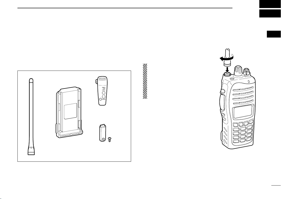
Supplied accessories ■
The following accessories are supplied: Qty.
Flexible antenna q .............................................................. 1
Battery pack w .................................................................... 1
Belt clip e ........................................................................... 1
Connector cover (with screw) r .................................... 1 set
Accessory attachments ■
Flexible antenna D
Connect the supplied flexible antenna to the antenna connector.
CAUTION:
• NEVER carry the transceiver by
holding only the antenna.
• DO NOT connect the antenna
other than listed on page 38.
• Transmitting without an antenna
will damage the transceiver.
1
1
Page 6
ACCESSORIES
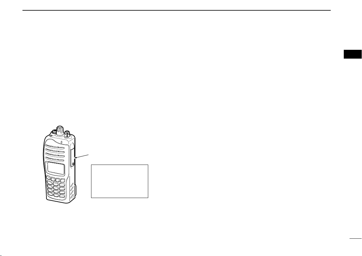
q
w
Battery release
button
Battery pack
q
w
1
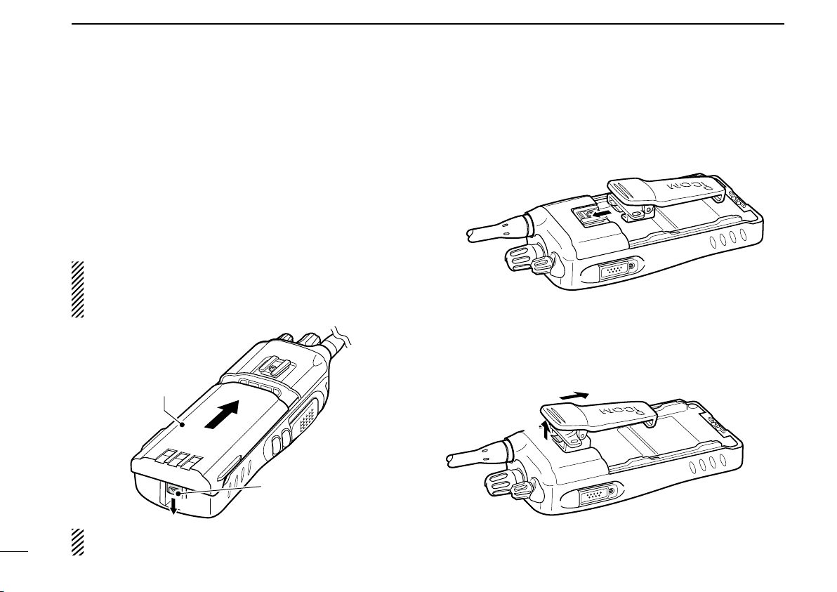
Battery pack D
To attach the battery pack:
Slide the battery pack on the back of the transceiver in the direction of the arrow (q), then lock it with the battery release button.
• Slide the battery pack until the battery release button makes a ‘click’
sound.
To remove the battery pack:
Push the battery release button in the direction of the arrow
(w) as shown below. The battery pack is then released, and
you can remove it.
NEVER remove or attach the battery pack when the transceiver is wet or soiled. This may result water or dust getting
into the transceiver/battery pack and may result in the
transceiver being damaged.
Belt clip D
To attach the belt clip:
Remove the battery pack if it is attached. q
Slide the belt clip in the direction of the arrow until the belt w
clip is locked and makes a ‘click’ sound.
To detach the belt clip:
Remove the battery pack if it is attached. q
Pinch the clip ( w q), and slide the belt clip in the direction of
the arrow (w).
NOTE: Keep the battery pack terminals clean. It’s a good
2
idea to occasionally clean them.
Page 7
D
q
w
Multiconnector
Connector
cover
q
w
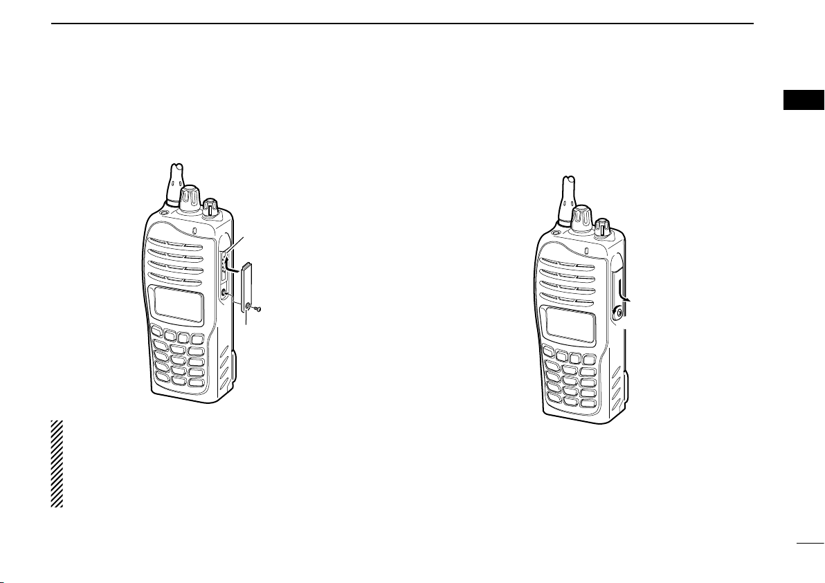
Connector cover
To attach the connector cover:
q Insert the connector cover into the multi-connector.
w Tighten the screw.
CAUTION:
Attach the connector cover when the optional speakermicrophone is not used.
Otherwise the terminals of the multi-connector may be
shorted by metal object, etc., and this could damage the
transceiver.
ACCESSORIES
To detach the connector cover:
q Unscrew the screw using a phillips screwdriver.
w Detach the connector cover for the speaker-microphone or
head-set connector.
1
1
3
Page 8
2
w
e
t
r
y
q
!1
!0
o
!2
u
i
Microphone
Speaker
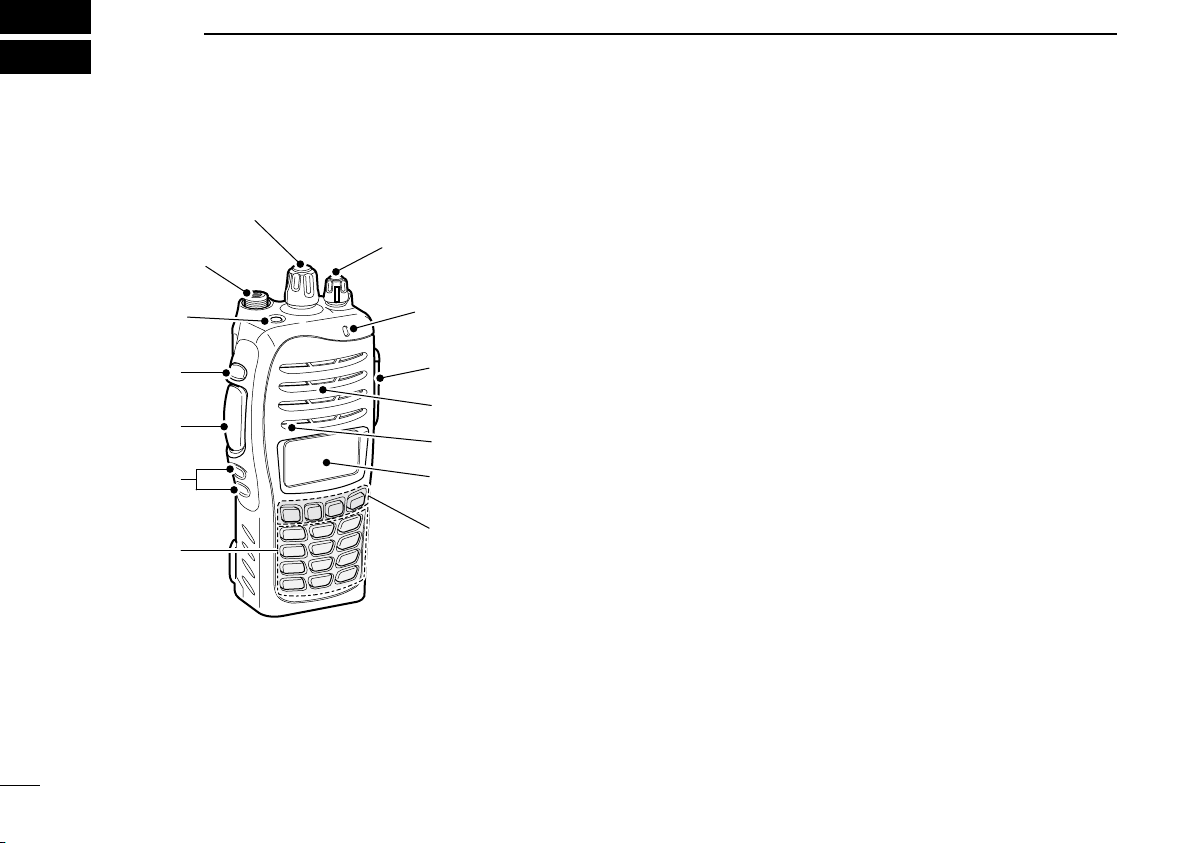
Front panel
■
4
PANEL DESCRIPTION
q ROTARY SELECTOR
Rotate to select the pre-programmed memory channels or
the operating zone.
(Depending on the pre-setting)
w ANTENNA CONNECTOR
Connects the supplied antenna.
e DEALER-PROGRAMMABLE KEY [Emer]
Desired functions can be programmed by your dealer.
((☞p. 7))
r DEALER-PROGRAMMABLE KEY [Side1]
Desired functions can be programmed by your dealer.
((☞p. 7))
t PTT SWITCH [PTT]
Push and hold to transmit; release to receive.
y DEALER-PROGRAMMABLE KEYS [Side2]/[Side3]
Desired functions can be programmed independently by
your dealer. ((☞p. 7))
u 10-KEYPAD (Depending on version)
The keypad allows you to enter digits to:
• Select memory channels
• Select tone channels
• Select DTMF codes (during transmit)
• Set TX codes
• Set BIIS status number
• Input text message for SDM operation.
• Start up with the password
Page 9
PANEL DESCRIPTION
Connector cover
NOTE: Attach the
connector cover when
the optional speakermicrophone is not used.
See ((� p. 3)) for details.
2
i DEALER-PROGRAMMABLE KEYS [P0] to [P3]
Desired functions can be programmed independently by
your dealer. ((☞p. 7))
o FUNCTION DISPLAY
Displays a variety of information such as an operating
channel number/name, 2/5-tone code, DTMF numbers,
selected function, etc.
!0 MULTI-CONNECTOR
Connect an optional speaker-microphone.
!1 BUSY/TRANSMIT INDICATOR
2
➥ Lights green while receiving a signal, or when the
squelch is open.
Lights red while transmitting. ➥
!2 VOLUME CONTROL [VOL]
Rotate to turn the power ON/OFF and adjusts the audio
level.
5
Page 10
PANEL DESCRIPTION
SET
CALA TXCU
TXC
q t iuyrew
o
!0
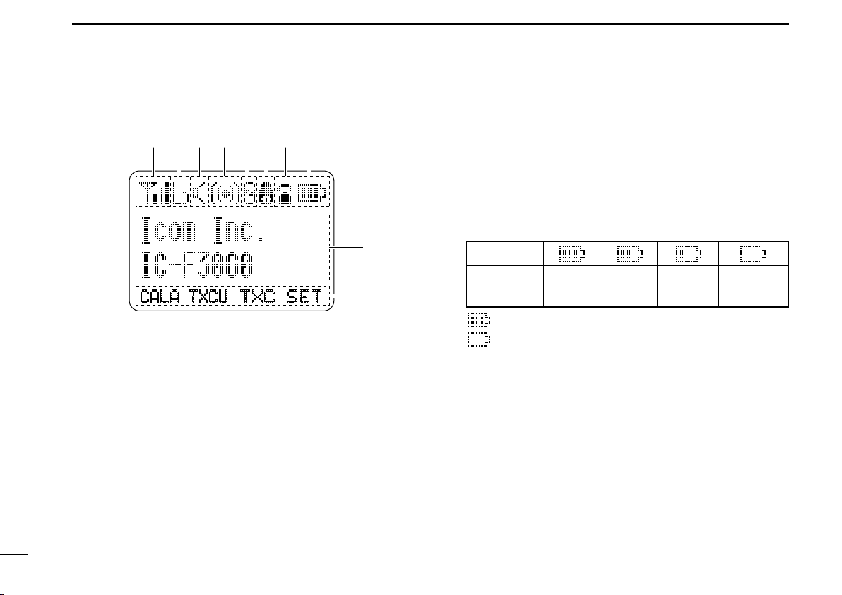
Indication
Full Middle
Charging
required
No battery
Battery level
blinks when the battery is exhausted.
blinks when the battery is over voltage.
2
Function display
■
q SIGNAL STRENGTH INDICATOR
Indicates relative signal strength level.
w LOW POWER INDICATOR
Appears when low output power is selected.
e AUDIBLE INDICATOR
Appears when the channel is in the ‘audible’ (unmute) ➥
condition.
Appears when the specified 2/5-tone/BIIS code is re- ➥
ceived.
6
r COMPANDER INDICATOR
Appears when the compander function is activated.
t SCRAMBLER INDICATOR
Appears when the voice scrambler function is activated.
y BELL INDICATOR
Appears/blinks when the specific 2/5-tone/BIIS code is re-
ceived, according to the pre-programming.
u CALL CODE MEMORY INDICATOR
Appears when the call code memory is selected.
i BATTERY INDICATOR
Indicates remaining battery power.
o ALPHANUMERIC DISPLAY
Displays an operating channel number, channel name, ➥
Set mode contents, DTMF code, etc.
The indication mode can be selected from 1 line or 2 ➥
lines. Ask your dealer for details.
• In this instruction manual, the LCD illustration is described
using the 2 lines indication mode.
!0 KEY INDICATOR
Indicate the programmed function of the front panel keys
([P0], [P1], [P2] and [P3]).
Page 11

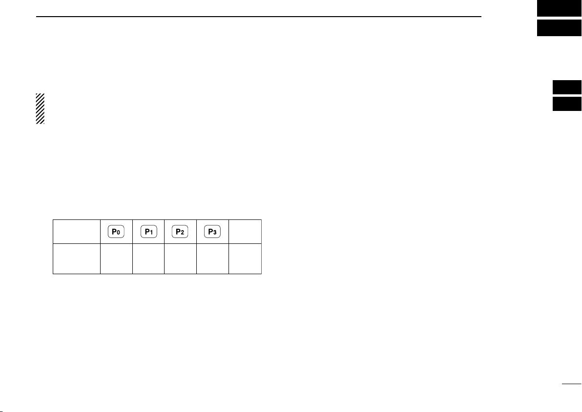
Programmable function keys
■
The following functions can be assigned to [Emer], [Side1],
[Side2], [Side3], [P0], [P1], [P2] and [P3] programmable
function keys.
Consult your Icom dealer or system operator for details concerning your transceivers programming.
If the programmable function names are bracketed in the following explanations, the specific key is used to activate the
function depends on the programming.
CH UP AND DOWN KEYS “UP” “DOWN”
Push to select an operating channel. ➥
Push to select a transmit code channel after pushing [TX ➥
Code CH Select].
Push to select a DTMF channel after pushing [DTMF Au- ➥
todial].
Push to select a scan group after pushing and holding ➥
[Scan A Start/Stop]/[Scan B Start/Stop].
Push to select a BIIS code, status number or SDM after ➥
pushing [Digital Button].
PANEL DESCRIPTION
What is “zone”?— The desired channels are assigned
into a zone according to the intended use for grouping. For
example, ‘Staff A’ and ‘Staff B’ are assigned into a “Business” zone, and ‘John’ and ‘Cindy’ are assigned into a “Pri-
vate” zone.
SCAN A KEY “SCNA”
This key’s operation depends on the Power ON Scan set- ➥
ting.
When the power ON scan function is turned OFF;
Push to start and cancel scanning operation. In case of
transmission during scan, cancels scanning.
When the power ON scan function is turned ON;
Push to pause scanning., then resumes scanning after
passing a specified time period. In case of transmission
during scan, scanning will be cancelled.
Push and hold this key for 1 sec. to indicate the scan ➥
group, then push [CH Up] or [CH Down] to select the desired group.
2
2
ZONE KEY “ZONE”
Push this key, then push [CH Up] or [CH Down] to select the
desired zone.
SCAN B KEY “SCNB”
Push to start and cancel scanning operation. In case of ➥
transmission during scan, pauses scanning. Scanning resumes after passing a specified time period.
Push and hold this key for 1 sec. to indicate the scan ➥
group, then push [CH Up] or [CH Down] to select the desired group.
7
Page 12

PANEL DESCRIPTION
2
SCAN ADD/DEL (TAG) KEY “SCAD”
Push to add or delete the selected channel to/from the scan
group.
PRIO A/B KEYS “PRA” “PRAR” “PRB” “PRBR”
Push to select Priority A or Priority B channel. ➥
Push and hold [Prio A (Rewrite)] to rewrite the Prio A ➥
channel.
MR-CH 1/2/3/4 KEYS “CH1” “CH2” “CH3” “CH4”
Push to select an operating channel directly.
MONI (AUDI) KEY “MON”
Activates one of (or two of) the following functions on ➥
each channel independently: (PMR or BIIS PMR operation only)
• Push and hold to un-mute the channel (audio is emitted; ‘Audible’
condition).
• Push to mute the channel (sets to ‘Inaudible’ only).
• Push to un-mute the channel (sets to ‘Audible’ only).
• Push after the communication is nished to send a ‘reset code.’
NOTE: The un-mute condition (‘Audible’ condition) may
automatically return to the mute condition (‘Inaudible‘ con-
dition) after a specified period depending on programming.
LIGHT KEY “LIGT”
Push to turn the transceiver’s backlight ON temporarily only
when the backlight function is turned OFF in user set mode.
LOCK KEY “LOCK”
Push and hold for 1 sec. to electronically lock all program- ➥
mable keys except the following:
[Call] (incl. Call A and Call B), [Moni(Audi)] and [Emergen-
cy].
Push and hold for 1 sec. again to turn the lock function ➥
OFF.
HIGH/LOW KEY “H/L”
Push to select the transmit output power temporarily or permanently, depending on the pre-setting.
• Ask your dealer for the output power level for each selection.
C.TONE CH ENT KEY “TSEL”
Push to select the continuous tone channel using [CH Up]/
[CH Down] to change the tone frequency/code setting. The
selected channel remains set as the continuous tone channel
until another channel is designated as such.
TALK AROUND KEY “TA”
Push to turn the talk around function ON and OFF.
• The talk around function equalizes the transmit frequency to the
receive frequency for transceiver-to-transceiver communication.
WIDE/NARROW KEY “W/N”
Push to toggle the IF bandwidth between wide and narrow.
• The wide passband width can be selected from 25.0 or 20.0 kHz using the CS-F3060 c l o n i n g s o f t w a r e . (PMR or BIIS PMR operation
only) Ask your Dealer for details.
8
Page 13

PANEL DESCRIPTION
2
DTMF AUTODIAL KEY “DTMA”
Push to enter the DTMF channel selection mode. Then se- ➥
lect the desired DTMF channel using [CH Up]/[CH Down].
After selecting the desired DTMF channel, push this key to ➥
transmit the DTMF code.
RE-DIAL KEY “DTMR”
Push to transmit the last-transmitted DTMF code.
CALL KEYS “CALL” “CALA” “CALB”
Push to transmit a 2/5-tone/BIIS ID code.
• Call transmission is necessary before you call another station depending on your signaling system.
• [Call A] and/or [Call B] may be available when your system employs
selective ‘Individual/Group’ calls. Ask your dealer which call is as-
signed to each key.
EMERGENCY KEY “EMR”
Push and hold for a specified period to transmit an emer- ➥
gency call.
When [Emergency Single (Silent)] or [Emergency Repeat ➥
(Silent)] is pushed, an emergency call is transmitted without a beep emission and LCD indication change.*
• If you want to cancel the emergency call, push (or push and
hold) the key again before transmitting the call.
• The emergency call is transmitted one time only or repeatedly
until receiving a control code depending on the pre-setting.
*BIIS PMR operation only
SURVEILLANCE KEY “SURV”
Push to turn the surveillance function ON or OFF.
When this function is turned ON, the beep is not emitted and
the LCD backlight does not light when a signal is received or
a key is pushed, etc.
TX CODE ENTER KEY “TXCE”
(PMR or BIIS PMR operation only)
Push to enter the ID code edit mode directly, for both
5-tone and BIIS. Then set the desired digit using [CH Up]/
[CH Down] or 10-keypad*. ((☞ p. 14))
*IC-F3062T/IC-F4062T (10-key type) only
TX CODE CHANNEL SELECT KEY “TXC”
Push to enter the ID code channel selection mode directly. ➥
Then set the desired channel using [CH Up]/[CH Down].
((☞ p. 14))
During ID code channel selection mode, push for 1 sec. to ➥
enter the ID code edit mode for 5-tone and BIIS. Then set
the desired digit using [CH Up]/[CH Down] or 10-keypad*.
((☞ p. 14))
*IC-F3062T/IC-F4062T (10-key type) only
TX CODE CHANNEL UP/DOWN KEYS “TXCU” “TXCD”
Push to select a TX code channel directly.
2
9
Page 14

PANEL DESCRIPTION
2
ID-MR SELECT KEY “IDMS”
(PMR or BIIS PMR operation only)
Recalls detected ID codes. ➥
• Push this key, then select the ID code using [CH Up]/[CH
Down].
• Up to 5 ID’s are memorized.
Push and hold to erase the selected ID’s. ➥
SCRAMBLER FUNCTION “SCR”
Push to toggle the voice scrambler function ON and OFF.
COMPANDER KEY “COMP”
Push to toggle the compander function ON and OFF.
The compander function reduces noise components from the
transmitting audio to provide clear communication.
USER SET MODE KEY “SET”
Push and hold to enter user set mode. ➥
• During user set mode, push this key to select an item, and
change the value or condition using push [CH Up]/[CH Down].
Push and hold this key again to exit user set mode. ➥
OPT OUT KEYS “OP1” “OP2” “OP3”
Push to control the output signal level of the optional ports in
the optional unit connector.
OPT MOMENTARY KEYS “O1M” “O2M” “O3M”
Push and hold to control the output signal level of the optional
ports in the optional unit connector.
DIGITAL BUTTON KEY “BIFN”
(BIIS operation only)
Push to select the call ID list, transmit message and ➥
standby condition. Toggles between queue channel and
received message record indication after queue channel
is selected.
Push and hold to select queue channel indication. ➥
STATUS UP/DOWN KEYS “BIUP” “BIDN”
(BIIS operation only)
While in the standby condition, push to display the transmit ➥
status indication and select a status number.
When a received SDM is displayed, push to cancel the ➥
automatic scroll and scroll the message manually.
When an SDM that contains more than 12 characters is ➥
displayed, push to scroll the message manually.
10
Page 15
Turning power ON
KEY
NUMBER
0
5
4
9
3
8
2
7
1
6
(Side3)
■
Prior to using the transceiver for the first time, the battery
pack must be fully charged for optimum life and operation.
((☞ p. 30))
BASIC OPERATION
D
Battery type selection
The battery type must be selected according to the attaching
battery type when tuning the transceiver ON.
3
2
3
Rotate [VOL] to turn the power ON. q
If the transceiver is programmed for a start up password, w
input the digit codes as directed by your dealer.
• 10-keypad can be used for password input depending on ver-
sion:
• The keys in the table below can be used for password input:
• The transceiver detects numbers in the same block as identical.
Therefore “01234” and “56789” are the same.
When the “PASSWORD” indication does not clear after in- e
putting 4 digits, the input code number may be incorrect.
Turn the power off and start over in this case.
While pushing and holding [Emer] and [PTT], rotate [VOL] ➥
to toggle the attaching battery type.
• After the display appears, release [Emer] and [PTT].
• “ DRY BATT” is displayed for about 3 sec. then “Lo” appears when
the battery case operation is selected.
• “LI-ION” is displayed for about 3 sec. when the Lithium-ion battery operation is selected.
• This operation may not be available depending on the pre-setting.
Ask your dealer for details.
11
Page 16

Selective calling
Non-selective calling
BASIC OPERATION
3
Channel selection
■
Several types of channel selections are available. Methods
may differ according to your system set up.
NON-ZONE TYPE:
Push [CH Up] or [CH Down], or rotate [ROTARY SELECTOR]* to select the desired operating channel, in sequence;
or, push one of [MR-CH 1] to [MR-CH 4] keys to select a
channel directly.
• Up to 16 pre-programmed channels can be selected via [ROTARY
SELECTOR].*
ZONE TYPE:
Push [Zone], then push [CH Up] or [CH Down] or rotate [RO-
TARY SELECTOR]* to select the desired zone.
AUTOMATIC SCAN TYPE:
Channel setting is not necessary for this type. When turning power ON, the transceiver automatically starts scanning.
Scanning stops when receiving a call.
*Depending on the pre-setting.
Call procedure
■
When your system employs tone signaling (excluding CTCSS and DTCS), the call procedure may be necessary prior
to voice transmission. The tone signaling employed may be
a selective calling system which allows you to call specific
station(s) only and prevent unwanted stations from contacting you.
Select the desired TX code channel or 2/5-tone code ac- q
cording to your System Operator’s instructions.
• This may not be necessary depending on programming.
• Refer to page 14 or 15 for selection.
Push the call key (assigned to one of the dealer program- w
mable keys: [Emer], [Side1], [Side2], [Side3], [P0], [P1],
[P2] and [P3]) or [PTT].
After transmitting a 2/5-tone code, the remainder of your e
communication can be carried out in the normal fashion.
12
Page 17

Receiving and transmitting
■
NOTE: Transmitting without an antenna may damage the
transceiver. See page 1 for accessory attachments.
Receiving:
Rotate [VOL] to turn the power ON. q
Push [CH Up] or [CH Down], or rotate [ROTARY SELEC- w
TOR]* to select the conventional system channel, in sequence.
*Depending on the pre-setting.
When receiving a call, adjust the audio output level to a e
comfortable listening level.
Transmitting:
Wait for the channel to become clear to avoid interference.
Push [Call] when initiating a call from your side. q
• Coded audio may be heard from the transceiver, then “ ” appears.
• This operation may not be necessary depending on your signal-
ing system. Ask your dealer for details.
While pushing and holding [PTT], speak into the micro- w
phone at a normal voice level.
Release [PTT] to return to receive. e
BASIC OPERATION
D
Transmitting notes
• Transmit inhibit function
The transceiver has several inhibit functions which restrict
transmission under the following conditions:
- The channel is in mute condition (‘Inaudible’ condition;
“
” does not appear.)
- The channel is busy.
- Un-matched (or matched) CTCSS is received.
(Depending on the pre-setting.)
- The selected channel is a ‘receive only’ channel.
• Time-out timer
After continuous transmission for the pre-programmed time
period, the time-out timer is activated, causing the transceiver
to stop transmitting.
• Penalty timer
Once the time-out timer is activated, transmission is further
inhibited for a period determined by the penalty timer.
3
3
NOTE: To maximize the readability of your signal;
1. Pause briefly after pushing [PTT].
2. Hold the microphone 5 to 10 cm (2 to 4 inches) from
your mouth, then speak into the microphone at a normal
voice level.
13
Page 18

BASIC OPERATION
3
D
TX code channel selection
If the transceiver has [TX Code CH Select] assigned to it,
the indication can be toggled between the operating channel
number (or name) and TX code channel number (or name).
When the TX code channel number (or name) is displayed,
[CH Up] or [CH Down] selects the TX code channel.
USING [TX CODE CH SELECT] KEY:
Push [TX Code CH Select]— a TX code channel number q
(or name) appears.
Push [CH Up] or [CH Down] to select the desired TX code w
channel.
Push [Call] (or [PTT] during MSK operation) to transmit the e
selected TX code.
Push [TX Code CH Select] again to return to the operating r
channel number indication.
USING [TX CODE CH UP]/[TX CODE CH DOWN] KEY:
If the transceiver has a [TX Code CH Up] or [TX Code CH
Down] key assignment, the programmed TX code channel
can be selected directly when pushed.
NOTE for PMR or BIIS PMR operation:
• The LCD indication does not change when the operating
channel number (or name) is displayed. (Depending on
the pre-setting)
• To check the selected TX code, push [TX Code CH Select].
DTX code number edit
(PMR or BIIS PMR operation only)
If the transceiver has [TX Code CH Select] or [TX Code Enter] assigned to it, TX code contents can be edited within the
allowable digits.
USING [TX CODE CH SELECT] KEY:
Push [TX Code CH Select] to enter the TX code channel q
selection mode.
• Select the desired channel before entering the TX code channel
selection mode if necessary.
Push and hold [TX Code CH Select] for 1 sec. to enter the w
TX code edit mode.
Push [TX Code CH Select] to select the desired digit to e
be edited.
• The digit to be edited blinks.
Push [CH Up], [CH Down] or 10-keypad* to set the desired r
digit.
Push [TX Code CH Select] to set the digit. The digit to the t
right will blink automatically.
• When the 10-keypad* is used for setting, the digit to the right will
blink automatically without pushing [TX Code CH Select].
y Repeat r and t to input all allowable digits.
u Push [Call] or [PTT] to transmit the edited TX code.
*IC-F3062T/IC-F4062T (10-key type) only
14
Page 19

USING [TX CODE ENTER] KEY:
Select the desired TX code channel via [TX Code CH q
Select]+[CH Up] or [CH Down], [TX Code CH Up] or [TX
Code CH Down].
Push [TX Code Enter] to enter the TX code edit mode. w
Push [TX Code Enter] to select the desired digit to be ed- e
ited.
• The digit to be edited blinks.
Push [CH Up], [CH Down] or 10-keypad* to set the desired r
digit.
Push [TX Code Enter] to set the digit. The digit to the right t
will blink automatically.
• When the 10-keypad* is used for setting, the digit to the right will
blink automatically without pushing [TX Code CH Enter].
y Repeat r and t to input all allowable digits.
u Push [Call] or [PTT] to transmit the edited TX code.
*IC-F3062T/IC-F4062T (10-key type) only
BASIC OPERATION
D
DTMF transmission
If the transceiver has [DTMF Autodial] assigned to it, the
automatic DTMF transmission function is available. Up to 8
DTMF channels are available.
TO SELECT A TX CODE:
Push [DTMF Autodial]— a DTMF channel appears. q
Push [CH Up] or [CH Down] to select the desired DTMF w
channel.
Push [DTMF Autodial] to transmit the DTMF code in the e
selected DTMF channel.
3
3
15
Page 20

BASIC OPERATION
3
User set mode
■
You can “customize” the transceiver operation to suit your preferences and operating style.
Entering the user set mode:
q Hold down [User Set Mode] for 1 second to enter the user
set mode.
w Push [User Set Mode] one or more times to select the ap-
propriate item. Then push [CH Up] or [CH Down] to set the
desired level or condition.
• Available set mode functions are Backlight, LCD contrast,
Beep, Beep Level, Ringer Level, SQL Level, AF Min Level,
Mic Gain, VOX Gain*, VOX Delay*, Battery Voltage and Signal
Moni.
* Appear only when the external VOX unit is connected.
e Hold down [User Set Mode] for 1 second again to exit the
set mode.
Scrambler function
■
The voice scrambler function provides private communication
between stations. The frequency inversion type is equipped
to all versions, moreover, the optional Rolling or Non-rolling
type can be available.
Push [Scrambler] to turn the scrambler function ON. q
• “ ” appears.
Push [Scrambler] again to turn the scrambler function w
OFF.
• “ ” disappears.
16
Page 21

BIIS OPERATION
CALLING
0500
TXCECALL BIFN
TXC
Appears Appears or
blinks
4
Setting example
■
The following functions are assigned to each programmable
key for display example. However, the assigned function can
be changed by your dealer. Ask your dealer for details.
[P0]; Call : Push to transmit a 5-tone/BIIS call
when the selected channel is a 5-tone
or BIIS channel.
• “CALL” is displayed on the key indicator.
[P1]; Digital Button : Push to select the call list ID/transmit
message, or to display the receive
message record for selection.
• “BIFN” is displayed on the key indicator.
When this key is pushed, “BIFN” is inverted as “ .”
[P2]; Null : No function is assigned.
[P3]; TX Code Enter : Push to enter the ID code edit mode
directly for both 5-tone and BIIS.
• “TXCE” is displayed on the key indicator.
[Emer]; Null : No function is assigned.
[Side1]; Moni(Audi) : Push this key after the communication
to send a ‘Clear down’ signal during
BIIS channel operation.
[Side2]/[Side3]; CH Up/Down
: While in the standby condition, selects
After pushing [Digital Button] or [TX
the operating channel.
Code CH Select], selects call list or TX
code channel, respectively.
Receiving a call
■
D
Individual call
When an individual call is received; q
• Beeps sound.
• “ ” appears and the mute is released.
• The programmed text message (e.g.“CALLING”) and the call-
ing station ID (or text) is displayed when the indication mode is 2
lines.
• The programmed text message (e.g.“CALLING”) and the call-
ing station ID (or text) is displayed alternately when the indication mode is 1 line, depending on the setting.
• “ ” appears or blinks depending on the setting.
Push and hold [PTT], then speak into the microphone at a w
normal voice level.
• TX indicator lights red.
Release [PTT] to return to receive. e
• BUSY indicator lights green while receiving a signal.
To finish the conversation, push [Moni(Audi)] to send the r
‘Clear down’ signal.
• Either station can send a ‘Clear down’ signal.
• “CLR DOWN” is displayed for 2 sec. (approx.).
• “ ” disappears and the transceiver returns to the standby condi-
tion.
3
4
17
Page 22

GROUP
1120
TXCECALL BIFN
TXC
Appears Appears or
blinks
<
QUEUE
>
–QUEUE!–
TXCECALL
TXC
BIFN
<
QUEUE
>
NO QUEUE
TXCECALL
TXC
BIFN
BIIS OPERATION
4
18
D
Group call
When a group call is received; q
• Beeps sound.
• “ ” appears and the mute is released.
• The programmed text message (e.g.“GROUP”) and the calling
station ID (or text) is displayed when the indication mode is 2
lines.
• The programmed text message (e.g.“GROUP”) and the calling
station ID (or text) is displayed alternately when the indication
mode is 1 line, depending on the setting.
• “ ” appears or blinks depending on the setting.
Push and hold [PTT], then speak into the microphone at a w
normal voice level.
• TX indicator lights red.
NOTE: Only one station is permitted to speak.
Release [PTT] to return to receive. e
• BUSY indicator lights green while receiving a signal.
To finish the conversation, push [Moni(Audi)] to send the r
‘Clear down’ signal.
• Either station can send a ‘Clear down’ signal.
• “CLR DOWN” is displayed for 2 sec. (approx.)
• “ ” disappears and the transceiver returns to the standby condi-
tion.
D
Displaying the received call record
— Queue indication
The transceiver memorizes the calling station ID in the memory. Up to 3 calls can be memorized, and the oldest call record is erased when a 4th call is received. However, once the
transceiver is powered OFF, the all records are cleared.
Push and hold [Digital Button] for 1 sec. q
• Displays following indication.
When a record is available
When no record is available
Push [CH Up] or [CH Down] to select the desired call. w
Push and hold [Digital Button] for 1 sec. again to return to e
the standby condition.
• When no operation is performed for 30 sec., the transceiver returns to the standby condition automatically.
Page 23

Transmitting a call
TXCECALL
TXC
BIFN
CALLING
0500
Appears
<
QUEUE
>
–QUEUE!–
TXCECALL
TXC
BIFN
■
A total of 3 ways for code selection are available—selecting
the call code from memory, entering the call code from the
keypad and calling back from the queue channel record.
D
Using call memory
While in the standby condition, push [Digital Button] to en- q
ter the call code memory channel selection mode.
• “ ” appears.
Push [CH Up] or [CH Down] to select the desired call w
code.
Push [Call] or [PTT]* to call. e
* PTT call can be made only when PTT call capability is permit-
ted.
NOTE: When no answer back is received, the trans-
ceiver repeats the call 3 times (default) automatically,
and
“WAIT” is displayed during each call. However, an
error beep sounds and
answer back is received after the calls.
Push [PTT] to transmit; release to receive. r
Push [Moni(Audi)] to send the ‘Clear down’ signal. t
“FAILED” is displayed when no
BIIS OPERATION
D
Calling back from the queue channel
While in the standby condition, push and hold [Digital But- q
ton] for 1 sec. to enter the queue memory channel selection mode.
Push [CH Up] or [CH Down] to select the desired record. w
Push [Call] or [PTT]* to call. e
* PTT call can be made only when PTT call capability is permit-
ted.
NOTE: When no answer back is received, the trans-
ceiver repeats the call 3 times (default) automatically,
and
“WAIT” is displayed during each call. However, an
error beep sounds and
answer back is received after the calls.
Push [PTT] to transmit; release to receive. r
Push [Moni(Audi)] to send the ‘Clear down’ signal. t
“FAILED” is displayed when no
4
4
19
Page 24

BIIS OPERATION
TXCECALL
TXC
BIFN
0500
4
D
Direct code entry
While in the standby condition, push [TX Code Enter] to q
enter the TX code edit mode.
• Code digit for editing blinks.
Push [TX Code Enter] to select the desired digit to be ed- w
ited.
• Digit for editing differs according to the setting.
Set the desired digit using [CH Up]/[CH Down] or 10-key- e
pad*.
*IC-F3062T/IC-F4062T (10-key type) only
Push [TX Code Enter] to set the digit, then the digit to the r
right will blink automatically.
• When the 10-keypad is used for setting, the digit to the right will
blink automatically without pushing [TX Code Enter].
Repeat t e and r to input all allowable digits.
y Push [Call] or [PTT]* to call.
* PTT call can be made only when PTT call capability is permit-
ted.
NOTE: When no answer back is received, the trans-
ceiver repeats the call 3 times (default) automatically,
and
“WAIT” is displayed during each call. However, an
error beep sounds and
answer back is received after the calls.
“FAILED” is displayed when no
u Push [PTT] to transmit; release to receive.
i Push [Moni(Audi)] to send the ‘Clear down’ signal.
For your information ✓
When the “UpDate” setting for the call code is enabled, the
set code is overwritten into the call code memory.
20
Page 25

■
TXCECALL
TXC
BIFN
RX Status 01
BASE
TXCECALL
TXC
BIFN
Thank you!
BASE
TXCECALL
TXC
BIFN
How about you?
BASE
Scrolls
BIIS OPERATION
4
Receiving a message
D
Receiving a status message
When a status message is received; q
• Beeps sound.
• The calling station ID (or text) and the status message is dis-
played alternately when the indication mode is 1 line, depending
on the setting.
Push [Moni(Audi)] to return to the standby condition. w
NOTE: Only the calling station ID (or text) is displayed
(no message is displayed alternately) when the scroll
timer is set to ‘OFF.’ In this case, push [Status Up]/ [Status Down] to display the status message manually.
D
Receiving an SDM
When an SDM is received; q
• Beeps sound.
• The calling station ID (or text) and the SDM is displayed alter-
nately when the indication mode is 1 line, depending on the setting.
When the received SDM includes more than 12 charac- w
ters, the message scrolls automatically, when the automatic scroll function is activated.
• Push [Status Up]/[Status Down] to scroll the message manually.
Push [Moni(Audi)] to return to the standby condition. e
(Short Data Message)
4
21
Page 26

BIIS OPERATION
TXCECALL
TXC
BIFN
MESSAGE
–
MSG! –
TXCECALL
TXC
BIFN
MESSAGE
–NO
MSG–
4
D
Received message selection
The transceiver memorizes the received message in the
memory. Up to 6 messages for status and SDM, or 95 charac-
ter SDM’s can be memorized. The oldest message is erased
when the 7th message is received. However, once the transceiver is powered OFF, all messages are cleared.
Push and hold [Digital Button] for 1 sec. q
• Displays queue memory.
Push [Digital Button] momentarily. w
• Displays message memory.
When a message is available
When no message is available
Push [CH Up] or [CH Down] to select the desired mes- e
sage.
• When selecting the SDM that includes more than 12 characters,
the message scrolls automatically when the automatic scroll
function is activated.
• Push [Status Up]/[Status Down] to scroll the message manually.
Push and hold [Digital Button] for 1 sec. again to return to r
the standby condition.
• When no operation is performed for 30 sec., the transceiver returns to the standby condition automatically.
22
Page 27

■
TXCECALL
TXC
BIFN
STATUS
01
TX Status 01
Status message is displayed.
BIIS OPERATION
4
Transmitting a status
D
General
The status message can be selected with the programmed
text, and the message text is also displayed on the function
display of the called station.
Up to 24 status types (1 to 24) are available, and the status
messages 22 and 24 have designated meanings.
Status 22: Emergency*
Status 24: GPS request
* The status 22 can also be used as a normal status message
by disabling the designated meaning. However, the status 24 is
fixed.
The status call can be sent with both individual and group
calls.
D
Transmitting a status
While in the standby condition, push [Digital Button], then q
push [CH Up] or [CH Down] to select the desired station/
group code.
Push [Digital Button] again, then push [CH Up] or [CH w
Down] to select the desired status message.
Or, you can select the desired status message using [Sta-
tus Up]/[Status Down] key directly.
Push [Call] or [PTT]* to transmit the status message to the e
selected station/group.
* PTT call can be made only when PTT call capability is permit-
ted.
• 2 beeps will sound and the transceiver returns to the standby
condition automatically when the transmission is successful.
4
23
Page 28

BIIS OPERATION
SDM is displayed.
TXCECALL
TXC
BIFN
MESSAGE 1
How are you?
TXCECALL
TXC
BIFN
MESSAGE 1
How are you?
Blinks
When [#] is pushed.
4
24
Transmitting an SDM
■
D
General
The short data message, SDM, can be sent to an individual
station or group stations. Also, 8 SDM memory channels are
available and the messages can be edited via PC programming.
D
Transmitting an SDM
While in the standby condition, push [Digital Button], then q
push [CH Up] or [CH Down] or rotate [ROTARY SELECTOR] to select the desired station/group code.
Push [Digital Button] again, then push [CH Up] or [CH w
Down] to select the desired SDM.
Or, you can select the desired SDM using [Status Up]/
[Status Down] key directly.
Push [Call] or [PTT]* to transmit the SDM to the selected e
station/group.
* PTT call can be made only when PTT call capability is permit-
ted.
• 2 beeps will sound and the transceiver returns to the standby
condition automatically when the transmission is successful.
(Short Data Message)
D
Programming an SDM memory
(IC-F3062T/IC-F4062T (10-key type) only)
During standby condition, push [Digital Button] twice, then q
push [CH Up] or [CH Down] to select the desired SDM to
be edited.
Push [ w M] or [#] to enter the message editing condition.
• The rst character blinks when [#] is pushed, the last character
blinks when [M] is pushed.
Push the appropriate digit key, [0] to [9], to enter the de- e
sired character.
• See the table at right for the available characters.
• Pushing [CH Up] also enters space, pushing [CH Down] deletes
the selected character.
Push [#] to move the cursor to the right, push [ r M] to move
the cursor to the left.
Repeat steps t e and r to set the desired text message.
y Push and hold [Digital Button] for 1 sec. to overwrite the
set content into the memory.
• Push [Digital Button] momentarily to cancel the editing and return to the original message indication.
Page 29

Key Characters
[0]
[1]
[2]
[3]
[4]
[5]
[6]
[7]
[8]
[9]
(space)
0][!|’”,?:_( )<>;
2BAabcC
3EDdefF
4HGghiI
5KJ jklL
6NMmnoO
7QPSpqrsR
9XWZwxyzY
8UTtuvV
1^@#M/–=\&%$+
■
BIIS OPERATION
4
Position data transmission
• Available characters
NOTE: A decimal point can only be written with the CSF3060
c l o n i n g s o f t w a r e . Pre-programmed characters
can be rewritten with the 10-keypad, except for the decimal point, as it is not included in the transceiver character
list, and cannot be displayed again.
When the optional cable (OPC-966) and a GPS receiver is
connected to the transceiver, the position (longitude and latitude) data can be transmitted automatically.
Ask your dealer or system operator for connection details.
The position data is transmitted when;
• Status 24 message is received
*When the status 24 message, GPS request, is received.
• Fully automatic
When automatic position transmission is enabled, send
the position data according to ‘Time Marker’ and ‘Interval
Timer’ settings.
• PTT is released
When ‘Send with Logoff’ is enabled.
- Set the ‘Log-In/Off’ item as ‘L-OFF.’
• After sending a status message
When ‘Send with Status’ is enabled.
• After sending an SDM
When ‘Send with SDM’ is enabled.
• After sending status 22 (Emergency)
When ‘Send with Emergency’ is enabled.
4
25
Page 30

BIIS OPERATION
4
Printer connection
■
When the optional cable is connected to the transceiver, a
printer can be connected to print out the received SDM content and the ID of the station who sent the message.
Ask your dealer or system operator for connection details.
Digital ANI
■
The own ID can be transmitted each time the PTT is pushed
(log-in) or released (log-off) during individual or group call
communications.
By receiving the ANI, the communication log can be recorded
when using a PC dispatch application.
In addition, when using the ANI with log-in, the PTT side tone
function can be used to inform you that the ID is sent and
voice communication can be performed.
Auto emergency transmission
■
When [Emergency Single (Silent)] or [Emergency Repeat (Silent)] is pushed, an emergency signal is automatically transmitted for the specified time period.
The status 22 (Emergency) is sent to the selected ID station,
and the position data is transmitted after the emergency signal when a GPS receiver is connected to the transceiver.
The emergency transmission is performed on the emergency
channel, however, when no emergency channel is specified,
the signal is transmitted on the previously selected channel.
There is no change in the function display or beep emission
during automatic emergency transmission.
Stun function
■
When the specified ID, set as a killer ID, is received, the stun
function is activated.
When the killer ID is received, the transceiver switches to the
password required condition. Entering of the password via
the keypad is necessary to operate the transceiver again in
this case.
26
Page 31

BIIS indication
■
The following indications are available for the BIIS operation
on a BIIS channel.
CONNECT : Individual/group call is successful.
OK : Message (status or SDM) transmission is suc-
cessful.
FAILED : No answer back is received.
WAIT : Appears during retry of the call (2nd call).
CLR DOWN : End the communication.
BUSY : Operating channel is in the busy condition.
Priority A channel selection
■
When one of the following operations is performed, the transceiver selects the Priority A channel automatically.
Priority A is selected when;
• Clear down signal is received/transmitted
- Set the ‘Move to PrioA CH’ item as ‘Clear down.’
• Turning the power ON
The Priority A channel is selected each time the trans-
ceiver power is turned ON.
• Status call
The Priority A channel is selected when transmitting a
status call.
- Enable the ‘Send Status on PrioA CH’ item in the BIIS
configuration.
BIIS OPERATION
4
4
27
Page 32

5
■
BATTERY CHARGING
Caution
Misuse of Lithium-ion batteries may result in the following
hazards: smoke, fire, or the battery may rupture. Misuse
can also cause damage to the battery or degradation of
battery performance.
• R DANGER! Use and charge only specified Icom battery
packs with Icom radios or Icom charger. Only Icom battery
packs are tested and approved for use and charge with
Icom radios or Icom charger. Using third-party or counterfeit
battery packs or charger may cause smoke, fire, or cause
the battery to burst.
D
Battery caution
• R DANGER! DO NOT hammer or otherwise impact the bat-
tery. Do not use the battery if it has been severely impacted
or dropped, or if the battery has been subjected to heavy
pressure. Battery damage may not be visible on the outside
of the case. Even if the surface of the battery does not show
cracks or any other damage, the cells inside the battery may
rupture or catch fire.
• R DANGER! NEVER use or leave battery packs in areas
with temperatures above +60˚C. High temperature buildup
in the battery, such as could occur near fires or stoves, inside a sun heated car, or in direct sunlight may cause the
battery to rupture or catch fire. Excessive temperatures may
also degrade battery performance or shorten battery life.
• R DANGER! DO NOT expose the battery to rain, snow,
seawater, or any other liquids. Do not charge or use a wet
battery. If the battery gets wet, be sure to wipe it dry before
using. The battery is not waterproof.
• R DANGER! NEVER incinerate used battery packs since
internal battery gas may cause them to rupture, or may
cause an explosion.
• R DANGER! NEVER solder the battery terminals or NEV-
ER modify the battery pack. This may cause heat generation, and the battery may rupture, emit smoke or catch fire.
• R DANGER! Use the battery only with the transceiver for
which it is specified. Never use a battery with any other
equipment, or for any purpose that is not specified in this
instruction manual.
• R DANGER! If fluid from inside the battery gets in your
eyes, blindness can result. Rinse your eyes with clean water, without rubbing them, and see a doctor immediately.
• R WARNING! Immediately stop using the battery if it emits
an abnormal odor, heats up, or is discolored or deformed. If
any of these conditions occur, contact your Icom dealer or
distributor.
• R WARNING! Immediately wash, using clean water, any
part of the body that comes into contact with fluid from inside the battery.
28
Page 33

• R WARNING! NEVER put the battery in a microwave oven,
high-pressure container, or in an induction heating cooker.
This could cause a fire, overheating, or cause the battery
to rupture.
• CAUTION: Always use the battery within the specified tem-
perature range for the transceiver (–25˚C to +55˚C) and the
battery itself (–20˚C to +60˚C). Using the battery out of its
specied temperature range will reduce the battery’s performance and battery life. Please note that the specified temperature range of the battery may exceed that of the transceiver. In such cases, the transceiver may not work properly
because it is out of its operating temperature range.
• CAUTION: Shorter battery life could occur if the battery is
left fully charged, completely discharged, or in an excessive
temperature environment (above +50˚C) for an extended
period of time. If the battery must be left unused for a long
time, it must be detached from the radio after discharging.
You may use the battery until the remaining capacity is
about half, then keep it safely in a cool dry place with the
temperature range as below:
–20˚C to +50˚C (within a month)
–20˚C to +40˚C (within three months)
–20˚C to +20˚C (within a year)
BATTERY CHARGING
D
Charging caution
• R DANGER! NEVER charge the battery pack in areas with
extremely high temperatures, such as near fires or stoves,
inside a sun heated car, or in direct sunlight. In such environments, the safety/protection circuit in the battery will
activate, causing the battery to stop charging.
• R WARNING! NEVER charge or leave the battery in the
battery charger beyond the specified time for charging. If
the battery is not completely charged by the specified time,
stop charging and remove the battery from the battery charger. Continuing to charge the battery beyond the specified
time limit may cause a fire, overheating, or the battery may
rupture.
• R WARNING! NEVER insert the transceiver (battery at-
tached to the transceiver) into the charger if it is wet or
soiled. This could corrode the battery charger terminals or
damage the charger. The charger is not waterproof.
• CAUTION: DO NOT charge the battery outside of the speci-
fied temperature range: BC-160 (0˚C to +40˚C). Icom recommends charging the battery at +20˚C. The battery may
heat up or rupture if charged out of the specified temperature range. Additionally, battery performance or battery life
may be reduced.
5
5
29
Page 34

BATTERY CHARGING
Power adapter
(A different type, or no power
adapter is supplied, depending on the version.)
About OPC-515L
White line:
Black line
:
*
Optional OPC-515L*
(for power source)
or CP-23L (for 12 V
cigarette lighter socket)
can be used instead of
the power adapter.
Transceiver
Battery
pack
Tu rn power OFF
5
Optional battery chargers ■
Rapid charging with the BC-160 D
The optional BC-160 provides rapid charging of the Li-ion
battery pack.
Charging period: Approximately 3 hours (with BP-232H)
The following items are additionally required:
• A power adapter (may be supplied with BC-160 depending
on version) or the DC power cable (OPC-515L/CP-23L).
30
D Regular charging with the BC-171
The optional BC-171 provides regular charging of the Li-ion
battery pack.
Charging period: Approximately 4 hours (with BP-230N)
The following items are additionally required:
• A power adapter (may be supplied with BC-171 depending
on version) or the DC power cable (OPC-515L/CP-23L).
Page 35

BATTERY CHARGING
Screws supplied
with the charger
adapter
AD-106
Plugs
Sockets
This illustration shows
the BC-119N.
AD-106 charger adapter
is installed in BC-119N.
Power adapter
(A different type, or no
power adapter is supplied,
depending on the version.)
About OPC-515L
White line: Black line
:
*
Optional OPC-515L*
(for power source)
or CP-23L (for 12 V
cigarette lighter socket)
can be used instead of
the power adapter.
Transceiver
Battery
pack
Tu rn power OFF
5
AD-106 installation D
The AD-106 c h a r g e r a d a p t e r must be installed into the BC119N or BC-121N before battery charging.
q Attach the plugs from the BC-119N/BC-121N to the AD-
106
c h a r g e r a d a p t e r .
w Secure the AD-106 into the holder space of the BC-119N/
BC-121N with the supplied screws.
Rapid charging with the BC-119N+AD-106 D
The optional BC-119N provides rapid charging of the Li-ion
battery pack.
Charging period: Approximately 3 hours (with BP-232H)
The following items are additionally required.
• AD-106
• A power adapter (may be supplied with BC-119N depending
on version) or the DC power cable (OPC-515L/CP-23L).
c h a r g e r a d a p t e r (purchase separately)
5
31
Page 36

BATTERY CHARGING
Transceiver
Battery
pack
AD-106 charger
adapters are installed
in each slot.
Power adapter
(Purchased
separately)
Tu rn power OFF
DC power cable (OPC-656*)
(Connect with a DC power supply;
13.8 V/at least 7 A)
*About the OPC-656
Red line: Black line:
Guide rail
Tabs
5
Rapid charging with the BC-121N+AD-106 D
The optional BC-121N allows up to 6 battery packs to be
charged simultaneously.
Charging period: Approximately 3 hours (with BP-232H)
The following items are additionally required.
• Six AD-106
•
A power adapter or the DC power cable (OPC-656)
32
c h a r g e r a d a p t e r s (purchase separately)
IMPORTANT!: Battery charging caution
Ensure the guide tabs on the battery pack are correctly
aligned with the guide rails inside the charger adapter.
(This illustration is described with the BC-160.)
CAUTION:
When using the OPC-515L/OPC-656 DC power cable
NEVER reverse the polarity when connecting the OPC-
515L/OPC-656 to a power source. This will ruin the battery
charger.
OPC-515L : White line: +, Black line: _
OPC-656 : Red line: +, Black line: _
Page 37

Optional battery case (BP-240)
q
BP-240
w
Fig.1
Fig.2
Fig.3
e
r
t
■
When using the optional battery case attached to the transceiver, install 6 × AAA (LR03) size alkaline batteries as illustrated at right.
Unhook the battery cover release hook ( q q), and open the
cover in the direction of the arrow (w). (Fig.1)
Then, install 6 w × AAA (LR03) size alkaline batteries.
(Fig.2)
• Install the alkaline batteries only.
• Be sure to observe the correct polarity.
Fit the cover in the direction of the arrow ( e e), then close
(r). And hook the battery cover release hook until it makes
a ‘click’ sound (t). (Fig.3)
CAUTION:
• When installing batteries, make sure they are all the
same brand, type and capacity. Also, do not mix new and
old batteries together.
• Keep battery contacts clean. It’s a good idea to clean battery terminals once a week.
• Never incinerate used battery cells since internal battery
gas may cause them to rupture.
•
Never expose a detached battery case to water. If the battery case gets wet, be sure to wipe it dry before using it.
NOTE: When the optional battery case is attached, the
battery type must be selected to “DRY BATT” when turning
the transceiver ON. ((☞ p. 11))
BATTERY CASE
6
5
6
33
Page 38

7
q w
Once the transceiver is locked in place,
it will swivel 360 degrees.
SWIVEL BELT CLIP
MB-93 contents
■
Qty.
Belt clip q .......................................................................... 1
Base clip w ........................................................................ 1
Attaching
■
Remove the battery pack if it is attached. (( q ☞p. 2))
Slide the base clip in the direction of the arrow until the w
base clip is locked and makes a ‘click’ sound.
Clip the belt clip to a part of your belt. And insert the trans- e
ceiver into the belt clip until the base clip inserted fully into
the groove.
Once the transceiver is locked in place, it swivels as illus- r
trated below.
34
Page 39

■
q
w
SWIVEL BELT CLIP
7
Detaching
Turn the transceiver upside down in the direction of the q
arrow and pull out from the belt clip.
Remove the battery pack if it is attached. (( w ☞p. 2))
Pinch the clip ( e q), and slide the base clip in the direction
of the arrow (w).
7
CAUTION!
HOLD THE TRANSCEIVER TIGHTLY, WHEN HANGING
OR DETACHING THE TRANSCEIVER FROM THE BELT
CLIP.
Otherwise the transceiver may not be attached to the
holder or swivel properly if the transceiver is accidentally
dropped and the base clip is scratched or damaged.
35
Page 40

8
Tu rn the transceiver
power OFF when
attaching or detaching the microphone.
Speaker
Belt clip
Microphone
TOP KEY
(for HM-170GP only)
Desired functions can
be programmed by
your dealer.
GPS ANTENNA
(for HM-170GP only)
PTT SWITCH
Push and hold to
transmit;
release to receive.
This illustration is desicribed with HM-170GP.
CAUTION: Attach the
multi connector snugly, but
do not overtighten.
A loose connection will allow water intrusion into the
connector; an overtightened connector will damage the connector pins in
the transceiver.
SPEAKER MICROPHONE
Optional HM-169/170GP ■
description
N
36
EVER immerse the connector in water. If the connector
becomes wet, be sure to dry it BEFORE attaching it to the
transceiver.
NOTE: The microphone is located at the top of the
speaker-microphone, as shown in the diagram above. To
maximize the readability of your transmitted signal (voice),
hold the microphone approx. 5 to 10 cm from your mouth,
and speak in a normal voice level.
To attach ■
Attach the connector of the speaker-microphone into the multi
connector on the transceiver and tighten the screw.
IMPORTANT: KEEP the connector cover attached to the
transceiver when the speaker-microphone is not in use.
((☞p. 3))
Water will not get into the transceiver even if the cover is
not attached, however, the terminals (pins) will become
rusty, or the transceiver will function abnormally if the
connector becomes wet.
Page 41

OPTIONS
9
D BATTERY PACKS
—*
1
2
Battery pack Voltage Capacity Battery life*
BP-230N 7.4 V
BP-232N 7.4 V
BP-232H
BP-240
1
*
When the power save function is turned ON, and the operating
periods are calculated under the following conditions;
TX : RX : standby = 5 : 5 : 90
*2 Operating period depends on the alkaline cells used.
7.4 V
Battery case for AAA
950 mAh (min.)
980 mAh (typ.)
1900 mAh (min.)
2000 mAh (typ.)
2250 mAh (min.)
2300 mAh (typ.)
(LR03) × 6 alkaline
7.35 hrs.
12 hrs.
14 hrs.
CHARGERS D
• BC-119N d e s k t o p c h a r g e r + AD-106 c h a r g e r a d a p t e r
+ BC-145S a c a d a p t e r
For rapid charging of battery pack. A power adapter is sup-
plied with the charger, depending on versions.
Charging time: Approximately 3 hours for the BP-232H.
•
BC-121N m u l t i -c h a r g e r + AD-106 c h a r g e r a d a p t e r (6 pcs.)
+ BC-157S a c a d a p t e r
For rapid charging of up to 6 battery packs (six AD-106s
are required) simultaneously. A power adapter should be
purchased separately.
Charging time: Approximately 3 hours for the BP-232H.
• BC-160
For rapid charging of battery pack. A power adapter is sup-
plied with the charger, depending on versions.
Charging time: Approximately 3 hours for the BP-232H.
• BC-171
For regular charging of battery packs. We recommend that
the BP-230N charging. A power adapter is supplied with the
charger, depending on versions.
Charging time:
d e s k t o p c h a r g e r + BC-145S a c a d a p t e r
d e s k t o p c h a r g e r + BC-147S a c a d a p t e r
Approximately 4 hours for the BP-230N.
The BP-232H cannot be charged with the BC-171.
BELT CLIPS D
• MB-93 s w i v e l b e l t c l i p
• MB-94 b e lt c l i p
Exclusive alligator-type belt clip.
• MB-96N/96F
l e at h e r b e lt h a n g e r
OPTIONAL UNITS D
• UT-96R 5t o n e u n i t
Provides 5-tone decoder capabilities.
• UT-109R/UT-110R s c r a m b l e r u n i t s
Non-rolling type (UT-109R)/Rolling type (UT-110R) voice
scrambler unit provides high communication security.
1
2
3
4
5
6
7
8
9
10
11
12
13
14
15
16
37
Page 42

OPTIONS
9
DC CABLES D
• CP-23L c i g a r e t t e l i g h t e r c a b l e
Allows charging of the battery pack through a 12 V cigarette
lighter socket. (For BC-119N/BC-160/BC-171)
• OPC-515L/OPC-656
d c p o w e r c a b l e s
Allows charging of the battery pack using a 13.8 V power
source instead of the power adapter.
OPC-515L : For BC-119N/BC-160/BC-171
OPC-656 : For BC-121N
OTHER OPTIONS D
• SP-13 e a r p h o n e
Provides clear receive audio in noisy environment.
• HM-131SC/HM-159SC
Combination speaker-microphone that provides convenient
operation while hanging the transceiver from your belt.
• MB-130
Vehicle mounting bracket for the BC-160 battery charger.
v e h i c l e c h a r g e r b r a c k e t
• VS-1SC v o x /p t t c a s e + HS-94/HS-95/HS-97 h e a d s e t
VS-1SC :
VOX/PTT switch box for hands-free operation, etc.
HS-94 : Ear-hook type
HS-95 : Neck-arm type
HS-97 : Throat microphone
• AD-52
e a r p h o n e a d a p t e r
Provides clear receive audio in noisy environment.
• HM-169
s p e a k e r -m i c r o p h o n e
Rugged type speaker-microphone.
• HM-170GP
s p e a k e r -m i c r o p h o n e
GPS speaker-microphone for BIIS mode operation.
s p e a k e r -m i c r o p h o n e
D ANTENNAS
• FA-SC25V/FA-SC55V/FA-SC25U/FA-SC57U/FA-SC72U
f l e x i b l e a n t e n n a s
VHF or UHF antennas.
FA-SC25V: Frequency range 136–150 MHz
FA-SC55V: Frequency range 150–174 MHz
FA-SC25U: Frequency range 400–430 MHz
FA-SC57U: Frequency range 430–470 MHz
FA-SC72U: Frequency range 470–520 MHz
• FA-SC56VS/FA-SC57VS/FA-SC73US
Shorter VHF or UHF antennas.
FA-SC56VS: Frequency range 150–162 MHz
FA-SC57VS: Frequency range 160–174 MHz
FA-SC73US: Frequency range 450–490 MHz
• FA-SC61VC/FA-SC61UC
c u t a n t e n n a s
FA-SC61VC: Frequency range 136–174 MHz
FA-SC61UC: Frequency range 380–520 MHz
Approved Icom optional equipment is designed for optimal
performance when used with an Icom transceiver.
Icom is not responsible for the destruction or damage to an
Icom transceiver in the event it is used with equipment that is
not manufactured or approved by Icom.
Some options may not be available in some countries. Please
ask your dealer for details.
s t u b b y a n t e n n a s
38
Page 43

OPTIONS
VS-1SC
Water protection cover
PTT switch
MIC/VOX gain
adjusting pot
VOX/PTT select switch
VOX function is OFF
CALA
SET
TXCU
TXC
CALA
SET
TXCU
TXC
VOX OFF VOX GAIN 3
VOX gain level 3
(default)
[Side2]
Push
[Side3]
9
About VS-1SC D v o x /p t t c a s e
The VS-1SC is a VOX/PTT unit for Icom handheld transceivers, and allows you hands-free operation.
An optional headset (HS-94, etc.) is required for operation.
• The VOX (Voice Operated Transmission) function starts transmission without pushing [PTT] when you speak into the microphone.
Then, when you stop speaking, the transceiver automatically returns to receive.
Features
➥ Equipped with a 9-pin Spring-plug type head SP/MIC plug
➥ Equipped with a PTT switch and revolving clip
➥ Water resistant construction
➥ Durable construction
D VOX gain and delay adjustment
q Attach the connector of the VS-1SC into the multi-connec-
tor on the transceiver, and tighten the screw.
• Slide the VOX/PTT select switch to the [VOX] side.
Enter the User Set mode. (( w ☞ p. 16))
Push [P0] several times to select the “VOX Gain” or “VOX e
Delay” items. Then, push [Side2] or [Side3] to set the desired level or option.
Rotate [VOL] to turn OFF the power to exit the User Set r
mode.
• VOX Gain
The VOX sensitivity level can be adjusted between 1 (minimum) and 6 (maximum), or turned OFF.
1
2
3
4
5
6
7
8
9
10
11
12
13
14
15
16
39
Page 44

OPTIONS
0.5 sec (min.)
(default)
CALA
SET
TXCU
TXC
CALA
SET
TXCU
TXC
VOX DLY0.5 VOX DLY3.0
3.0 sec (max.)
[Side2]
Push
[Side3]
9
• VOX Delay
The VOX delay time can be set to between 0.5 and 3.0 seconds (in 0.5 second steps).
The VOX Delay is the amount of time the transmitter stays
ON after you stop speaking.
NOTE: The MIC/VOX gain level can be adjusted via the
Adjusting pot using a thin screw driver.
40
Page 45

COUNTRY CODE LIST
10
• ISO 3166-1
Country Codes Country Codes
1
Austria
2
Belgium
3
Bulgaria
4
Croatia
5
Czech Republic
6
Cyprus
7
Denmark
8
Estonia
9
Finland
10
France
11
Germany
12
Greece
13
Hungary
14
Iceland
15
Ireland
16
Italy
17
Latvia
AT
BE
BG
HR
CZ
CY
DK
EE
FI
FR
DE
GR
HU
IS
IE
IT
LV
18
Liechtenstein
19
Lithuania
20
Luxembourg
21
Malta
22
Netherlands
23
Norway
24
Poland
25
Portugal
26
Romania
27
Slovakia
28
Slovenia
29
Spain
30
Sweden
31
Switzerland
32
Turkey
33
United Kingdom
LI
LT
LU
MT
NL
NO
PL
PT
RO
SK
SI
ES
SE
CH
TR
GB
1
2
3
4
5
6
7
8
9
10
11
12
13
14
15
16
41
Page 46

MEMO
Page 47

MEMO
Page 48

< Intended Country of Use >
AT
FI
IT
PL
GB
RO
BE
FR
LV
PT
IS
TR
CY
DE
LT
SK
LI
HR
CZ
GR
LU
SI
NO
DK
HU
MT
ES
CH
EE
IE
NL
SE
BG
A-6489D-1EUPrinted in Japan
©
2006–2014 Icom Inc.
Printed on recycled paper with soy ink.
e
1-1-32 Kamiminami, Hirano-ku, Osaka 547-0003, Japan
 Loading...