

Page 1

HF/50MHz TRANSCEIVER
|7760
A New Innovative Shack Style
A New Innovative Shack Style
Full Control Head with Separated RF Deck
Full Control Head with Separated RF Deck
Page 2

High Power & Clean Transmit Signal for
A New Innovative Shack Style
In today’s connected world, the IC-7760 introduces a new connected system consisting of a control head and
RF deck, connected with a commercially available control (LAN) cable. This concept increases the exibility of
your station installation, making more space available on the desktop by placing the RF deck in an area closer
to the antenna feed point. In addition to the direct connect feature, control head to RF deck, utilize your home
network to make any tabletop your shack and a PC is not required!
Page 3

G
reat Strength in
C
ontests and
DX H
unting
Feature 01
Full Control Head
with Separated RF Deck
The IC-7760 consists of a separate control head and RF deck and
uses a control cable for connecting between them. It increases the
flexibility of the installation. A control cable (3 m, 9.8 ft) is supplied
with the radio, and a commercially available LAN cable* can be used
to install the RF deck in a more remote location. It enables the RF
deck to be placed in a rack or other location away from the station
desktop, providing a quiet shack environment away from the noise of
the fan used to dissipate the heat generated by the RF deck.
* LAN cable: Cat5e or higher.
Cable length: Maximum 100 m, 328 ft
Feature 02
Supports In-house Remote Operation
Through a Home LAN Connection
The IC-7760 can be connected to the
control head and RF deck through a wired
home LAN network*. This gives the user
even greater flexibility of the RF deck.
Because of its simple configuration that
does not require a PC, the control head of
the IC-7760 can be moved anywhere in
the house and operated not only from the
shack but also from the living room, etc.,
as long as a LAN connection is available.
* Communication between the control head and the RF deck depends on the network
environment in which it is used.
Gigabit Ethernet is required. The control head can be used on a different network segment
than the RF deck such as over a network switch.
In-house Remote Operation
2F
1F
Page 4
Feature 03
Dual, Independent Receivers
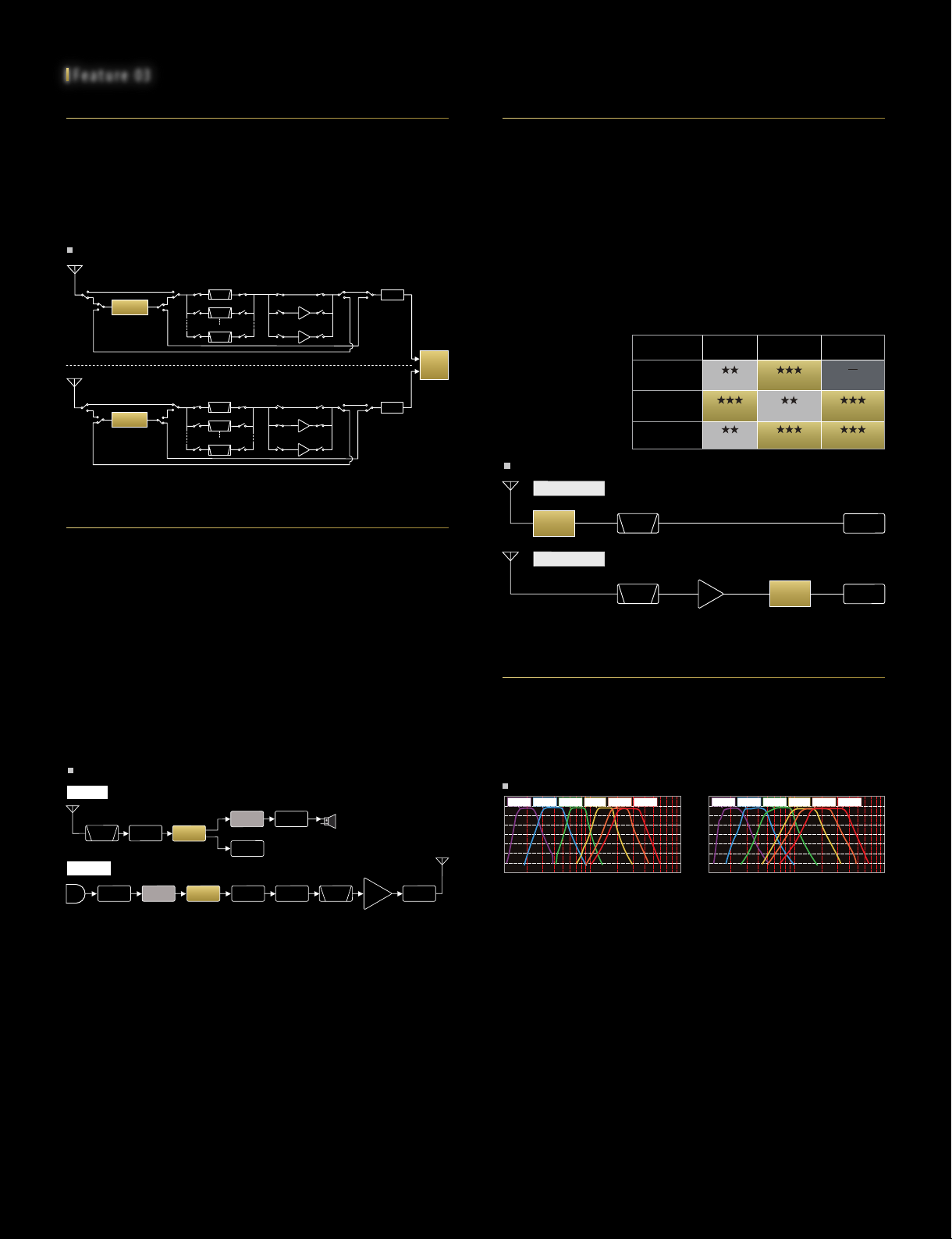
The IC-7760 has independent MAIN/SUB receivers, from the antenna to
the speaker, so that one receiver section has no effect on the other,
providing simultaneous reception of two signals in different bands/modes with identical performance. As with the IC-7851, dual spectrum
scopes provide simultaneous display of the MAIN and SUB bands
allowing the operator to see the changing band conditions.
Receiver Block Diagram
MAIN Band
SUB Band
(DIGI-SEL ON, PREAMP OFF)
DIGI-SEL
(DIGI-SEL ON, PREAMP ON)
DIGI-SEL
1.8 MHz
BPF
3.5 MHz
BPF
50 MHz
BPF
1.8 MHz
BPF
3.5 MHz
BPF
50 MHz
BPF
PREAMP1
PREAMP2
PREAMP1
PREAMP2
A/D
FPGA
A/D
Advanced RF Direct Sampling System
The IC-7760 adopts the RF direct sampling
system, in which RF signals are directly
converted to digital signals and the signals are
processed by an FPGA (Field Programmable
Gate Array). This system avoids non-linear
distortions that occur in mixer stages during
the analog signal processing. In addition, by
employing DSP units in both the RF deck and
control head, the IC-7760 is able to handle
complex audio path switching due to various
interface inputs and outputs, while minimizing
delay in a home LAN environment.
Block Diagram Overview
Receive
FPGA
DSP
Display
D/A
BPF
Transmit
A/D
A/D
FPGA
DSP
DSP + FP GA Unit ( RF Deck)
DSP Unit (Control Head)
D/A
ALC
BPF
PA
LPF
DIGI-SEL and Preamp
The DIGI-SEL (Digital Pre-selector) is highly effective in rejecting
out-of-band strong signals such as from broadcasting stations or
multi-multi operation. In conventional models (such as IC-7850/51 or
IC-7610), the DIGI-SEL circuit was located soon after the RF input
(antenna) to prevent signal distortion by out-of-band interference. Even
if the preamp was turned ON, the noise figure (receiver sensitivity)
could not be improved, as DIGI-SEL had an insertion loss due to its
narrow bandwidth. In the IC-7760, which is a direct sampling system,
DIGI-SEL prevents overflow (OVF) due to unwanted out-of-band signals
rather than signal distortion, and the preamp uses the A/D converter to
take full advantage of its dynamic range. When preamp is turned ON in
the IC-7760, the preamp enhances the intended signal first, then
DIGI-SEL filters out
unwanted out-of-band
signals. This makes it
possible that the
preamp works
together with
DIGI-SEL.
Block Diagram Overview
Low Distortion
DIGI-
SEL
High Gain
IMD
PREAMP ON
DIGI-SEL ON
PREAMP ON
DIGI-SEL ON
DIGI-SEL: ON / PREAMP: OFF
(Fine) (Superb)
(Superb)
(Fine)
BPF
DIGI-SEL: ON / PREAMP: ON
BPF
PREAMP
Sensitivity
(Fine)
(Superb) (Superb)
DIGI-
SEL
Overow
(Decent)
(Superb)
A Total of 15-separated BPF
While the previous model covered HF bands with a 9-separated BPF
(Band Pass Filter)
In addition, by employing sharp filters specialized for each amateur
band, the BPF efficiently attenuates out-of-band interference signals in
the RF stage, and prevents overflow at the A/D converter.
BPF Characteristics
[dB]
1.8
MHz
3.5
-10
-20
-30
-40
-50
-60
2 3 4 5 6
1
Showing primary BPF for HF amateur bands
, the IC-7760 uses an 11-separated BPF in HF bands.
60 70 80 90 100
[MHz]
[dB]
-10
-20
-30
-40
-50
-60
1.8
1
MHz
3.5
MHz7 MHz
2 3 4 5 6
MHz7 MHz
7 8 910 20 30 40 50
14
MHz
28
MHz
21
MHz
<IC-7610><IC-7760>
28
21
MHz
14
MHz
7 8 9 10 20 30 40 50
MHz
A/D
A/D
60 70 80 90 100
[MHz]
HF/50 MHz TRANSCEIVER
|7760
Page 5
Feature 04
Feature 05
DPD (Digital Pre-Distortion) Technology
The DPD function corrects non-linear distortion at the final amplifier by
applying inverse distortion in advance. A clean signal transmission is
achieved while providing 200 W of high output power at the same time.
The DPD function also works at the 1 kW output in combination with
the IC-PW2*.
* DPD feedback cable OPC-2501 is required when using with the IC-PW2.
DPD OFF (Signal Received on the IC-7300) DPD ON (Signal Received on the IC-7300)
No spurious emission observed
100% Duty Cycle at 200 W Output
The IC-7760 uses a 450 W-class 65 V LDMOS-FET in the PA section,
combined with a large heatsink and effective cooling system to achieve a
generous 200 W full power full duty operation*. Continuous FT8 mode
operation is also possible. Furthermore, modulation and frequency conversion
are made through digital signal processing, the D/A converter directly outputs
the transmit frequency, achieving the purest transmission C/N.
* 200 W and 1 hour continuous transmission with 100 V AC input (at ambient temperature 25˚C.)
Dual Display Control Head
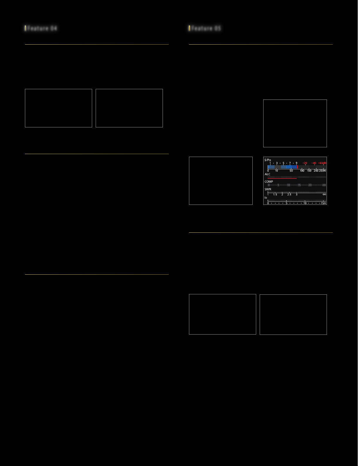
The IC-7760 control head has main and sub dual displays. The displays
are one 7-inch-wide main display (800
2.4-inch sub display (320
× 240 pixels) and both displays are touch
screens. The main display shows information necessary for operation,
including MAIN/SUB operating frequencies, and setting/ operating
status of each function.
The 2.4-inch, sub-display, can show the filter effect, various meters, and a
band stacking register. The filter
effect screen can display the IF
filter passband width and IF filter
shape superimposed on the IF
filter passband signal. This
function shows you visible images
of twin PBTs, manual notch
effects. The improved visibility of
information enhances operability
and ensures smoother operation.
Band Stacking Register
× 480 pixels, WVGA) and one
Filter Effect Example
Various Meters Example
(S/Power, ALC, COMP, SWR, Id)
RF Deck Front
Effective Cooling System with Four FansPA Unit with a Large Heatsink
Built-in Automatic Antenna Tuner
The IC-7760 incorporates a mechanical relay type internal antenna
tuner as a first for our 200 W
models. It provides faster tuning
than the conventional variable
capacitor type. Once tuned, the
matching information is
automatically recalled the next time
the frequency is selected,
facilitating smooth band changes
and multi-band operation.
Antenna Tuner Unit
Dual Spectrum Scope and Waterfall
The dual Spectrum Scope provides excellent sweep speed, resolution,
and a wide dynamic range of 100 dB with FPGA, DSP and CPU
combined processing for main and sub bands. It can also monitor two
different bands at the same time, which is useful for monitoring conditions
and during contests. In the Continuous SCROLL mode, a wide bandwidth
exceeding 1 MHz can be seen on the scope screen. The waterfall display
shows changes in the frequency spectrum vertically, enabling the user to
find a weak signal that is difficult to detect with the spectrum scope.
Increases QSO possibilities without missing weak DX stations.
Top-to-bottom Dual Scope Example
Left-to-right Dual Scope Example
Page 6

Feature 06
Dual Speakers
RC-28 for a Second VFO Knob
The IC-7760 is also equipped with dual
speakers. By separating the MAIN/SUB
audio into left and right speakers,
respectively, distinguishing the audio during
Dualwatch operation is improved.
MAIN/SUB audio can be set for stereo or
mono output from both speakers.
MAIN/SUB Dual Speakers
PRESET FT8 Menu
Introduced with the IC-7300 as FT8 is actively used around the world in everyday
operation as well as with DXpeditions. FT8 can be easily set up by simply
selecting it from the [Preset] memory and
all necessary items can be set at once.
Moreover, when returning to the normal
settings from FT8, simply select [Normal]
memory for a smooth transition. In addition,
up to 3 [Preset] memories can be written to
preset SSTV as well as future new digital
modes to be supported.
FT8 Mode Preset
Automatic Contest Serial Numbering
This function is powerful in CW and RTTY
contests. Each time the pre-programmed
memory is transmitted, the serial number is
automatically counted from 001. The serial
number can be set in multiple locations to
ensure that the contest number is reliably
copied.
Contest Serial Numbering Example
Audio Scope Flexibility
By connecting the optional RC-28 via
USB connection, the SUB band tuning of
the IC-7760 can be conveniently
operated with your fingertips. MAIN/SUB
switching buttons can be assigned to the
F-1 and F-2 buttons on the RC-28 and it
can operate as the main dial for both
MAIN and SUB bands.
Use Image of the Optional RC-28
SD Card Slot
An SD card slot is provided as an interface for data storage. In addition to voice
recordings of outgoing and incoming calls, RTTY/PSK decode logs, captured images of
the display, user settings, and firmware
updates can be saved in the storage. Voice
memories sent in Phone modes, and
message memories sent in CW/RTTY/PSK
modes, can also be stored. In addition,
when an operator is replaced, the operator
can simply load their preferred settings from
the storage to immediately start operating.
SD Card Slot
Touch Screen and Multi-Dial Knob
The combination of the touch screen and
the multi-dial knob offers easy access to
various settings. When the multi-dial knob is
pressed, menu items appear on the right
side of the display near the dial. Touch that
menu to select an item, then turn the
multi-dial knob to adjust the level, providing
much faster access to various functions
such as RF power, microphone gain,
DIGI-SEL, and notch functions.
Multi-Function Menu
The Audio Scope screen shows the transmit and received signal’s frequency
components on the FFT scope, and its waveform components on the
Oscilloscope. The Audio Scope makes it easy to monitor signal characteristics
such as microphone compressor level, filter width, and notch filter. You can monitor
received CW keying wave forms in the Oscilloscope.
Audio Scope Example
CW Keying Form Example
RS-BA1 – Internal Server
Whether from a remote part of your home QTH, or at a remote location
somewhere around the world, the RS-BA1 Version 2 software enables you to
operate your IC-7760.
The Dualwatch operation and dual spectrum scopes with the waterfall functions
can be used on your remote PC. With the addition of an Ethernet connector, a
base station computer is not required.
Page 7
I/Q Signal Output
External Display Connection
I/Q signals received by the IC-7760 can be output from a dedicated I/Q signal connector
(USB on the RF deck) to a PC for digital output. Using the I/Q signals on the HDSDR*,
you can listen to received signals, or display the spectrum
scope on the PC. Used in combination with the CW
Skimmer* or N1MM Logger+*, you can virtually decode
all Morse signals in the operating band. This function
is particularly useful for contesting and DX hunting,
and effective callback during split operation.
* USB I/Q driver package can be downloaded from the Icom web site.
HDSDR, CW Skimmer and N1MM Logger+ software are not
supplied from Icom.
USB Connector on the RF Deck
(USB 3.0 cable required)
Other Outstanding Features
RX Antenna
• BNC type RX IN/OUT connectors for a receiver antenna or
external BPF/preamp connection
CW Mode
• FPGA-controlled CW keying waveform shaping
• Multi-function electronic keyer
• CW pitch control from 300 Hz ~ 900 Hz (5 kHz step)
• Auto repeat function
• Normal or short Morse number style
• Double key jack system
• Full break-in and semi break-in
• CW auto tuning
• APF (Audio Peak Filter) function adjustable filter shape,
width, and AF level
• 136 kHz band operation (EUR version only)
Receiver
•
30 kHz ~ 60 MHz receiver
• Two types of preamps
Preamp 1: Wide dynamic range preamp
Preamp 2: High gain preamp
(Some frequencies are not guaranteed.)
• 3 dB ~ 45 dB variable attenuator (3 dB step)
•
IP+ function improves 3rd order intercept point performance
• Main/Sub band tracking function for diversity reception
• Twin peak audio filter for the RTTY mode
• RTTY/PSK encoder and decoder
• Adjustable AGC time constant from 0.1 to 6 seconds
(FM mode is fixed)
Transmitter
• TX monitor function
• All mode power control
• VOX (Voice Operated Transmission) capability
• BNC type transverter connector
• Microphone equalizer
• Adjustable transmit bandwidth
• 50 CTCSS tones
• Transmit Power Limit function for each band
Operation
•
Memo pad stores up to 10 operating frequencies and modes
• Quick split function
The IC-7760 has an external
display connector (DVI-D) on the
control head to output digital
signals of the main display to an
external display without signal
degradation. The main display can
be mirrored on a large external
display.
• Quick Dualwatch function
• RF gain and squelch control with a knob
• RIT and TX variable up to 9.999 kHz
• UTC/local clock and timer function
• 1 Hz pitch tuning and display
• Dial lock and panel lock functions
• Adjustable main dial brake
• External speaker jacks for Main and Sub receivers
• Screen saver function
• Multi-function meter (S-meter, Power, ALC, COMP, SWR,
Id, Vd and TEMP)
• Auto tuning step function
• AH-730 external antenna tuner control
(When the AH-730 is connected, output power of the specified
antenna terminal is automatically set to 100 W or less)
• MAIN/SUB AF mute
• Adjustable LCD/LED backlight
• USB port for optional RC-28, keyboard, mouse and USB
flash drive connection
External Display
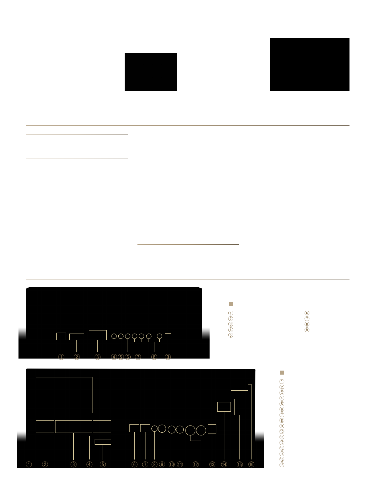
Rear Panel View
Control Head
RF Deck Connector
External Display Connector (DVI-D)
USB Connectors
External Keypad Jack
Electronic Keyer Jack
RF Deck
Antenna Connectors
Transverter Connector (BNC)
RX Antenna IN/OUT Connectors (BNC)
Reference Frequency Input (10 MHz)
Tuner Control Socket
Control Head Connector
LAN (Ethernet) Connector
CI-V Remote Control Jack
Key Jack
ALC Input Jack
SEND Control Jack
Accessory Sockets
USB Connector (I/Q OUT)
Ground Terminal
AC Power Socket
Main Power Switch
SEND Control Jack
LINE IN/OUT Jacks
External Speaker Jacks
DC IN Jack
Page 8
HF/50MHz TRANSCEIVER |7760
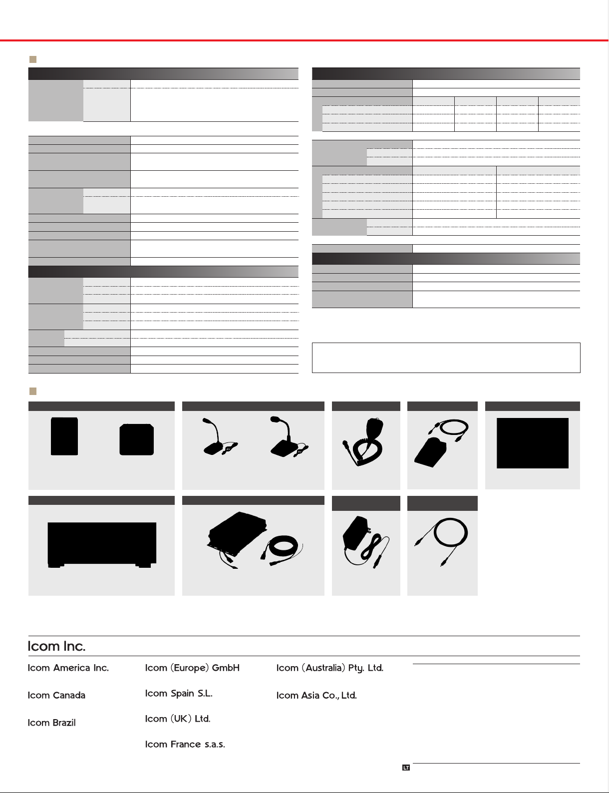
SPECIFICATIONS
GENERAL
1
Receiver*
Frequency
coverage
*1 USA version. Varies according to version. *2 Guaranteed range: 0.100 ~ 29.999, 50.000 ~ 54.000 MHz.
3
*
Some frequency bands are not guaranteed.
Transmitter*
Mode
Number of channels
Antenna connectors
Power supply requirement
Power
consumption
Tx
Rx
Operating temperature range
Frequency stability
Frequency resolution
Dimensions
(W × H × D)
(projections not included)
Weight (approximately)
0.030 ~ 60.00 MHz*
1.800 ~ 1.999, 3.500 ~ 3.999, 5.255 ~ 5.405*
7.000 ~ 7.300, 10.100 ~ 10.150, 14.000 ~ 14.350,
1
18.068 ~ 18.168, 21.000 ~ 21.450, 24.890 ~ 24.990,
28.000 ~ 29.700, 50.000 ~ 54.000 MHz
USB, LSB, CW, RTTY, PSK31/63, AM, FM
101
(99 regular, 2 scan edges)
SO-239 × 4 (50 Ω unbalanced, Tuner off)
BNC × 1 (RX antenna In/Out)
RF deck 90 ~ 264 V AC
Control head 15.0 V DC ±0.75 V
800 VA
RF deck + Control head 150 VA typ. (Stand-by/Max. audio)
Control head 3.0 A (Max. audio at 15.0 V DC)
0 ˚C ~ +50 ˚C; 32 ˚F ~ 122 ˚F
Less than ±0.5 ppm
1 Hz (minimum)
RF deck 425 × 149 × 442 mm; 16.7 × 5.9 × 17.4 in
Control head 340 × 118 × 103.5 mm; 13.4 × 4.6 × 4.1 in
RF deck 15.8 kg; 34.8 lb, Control head 2.3 kg; 5.1 lb
2
(with BC-267A/E)
(0˚C ~ +50˚C; 32˚F ~ 122˚F)
TRANSMITTER
SSB/CW/FM
Output power
(HF/50 MHz)
AM
Transverter
Modulation
system
Spurious
emissions
SSB
AM
FM
Unwanted emission
Out of band emission
Carrier suppression
Unwanted sideband
Microphone impedance
1 ~ 200 W
0.25 ~ 50 W
More than –20 dBm
Digital P.S.N. modulation
Digital Low power modulation
Digital Reactance modulation
HF bands: Less than –50 dB , 50 MHz: Less than –66 dB
HF bands: Less than –40 dB, 50 MHz: Less than –60 dB
More than 50 dB
More than 50 dB
600 Ω
RECEIVER
Receiver system
3
Intermediate frequency
Sensitivity*
4
(Filter shape: Soft)
SSB/CW
(at 10 dB S/N, BW= 2.4 kHz)
AM (at 10 dB S/N, BW = 6 kHz)
FM
(at 12 dB SINAD, BW = 15 kHz)
4
HF: Preamp 1 ON, 50 MHz: Preamp 2 ON
*
Direct Sampling Superheterodyne
12 kHz
0.5 ~ 1.799 MHz 1.8 ~ 29.999 MHz 28.0 ~ 29.7 MHz 50 MHz band
– 0.16 μV typ. – 0.13 μV typ.
6.3 μV typ. 2.0 μV typ. – 1.0 μV typ.
– – 0.5 μV typ. 0.32 μV typ.
Squelch sensitivity (Threshold)
SSB
FM
Selectivity (Filter shape: Sharp)
SSB (BW: 2.4 kHz)
CW (BW: 500 Hz)
RTTY (BW: 500 Hz)
AM (BW: 6 kHz)
FM (BW: 15 kHz)
Spurious and
image rejection
5
ADC Aliasing frequency: 122.880 MHz – RX frequency
*
HF bands
50 MHz band
Audio output power
Less than 3.2 μV
(Preamp ON)
Less than 0.32 μV (Preamp ON)
More than
2.4 kHz/–6 dB
500 Hz/–6 dB
500 Hz/–6 dB
6.0 kHz/–6 dB
12.0 kHz/–6 dB
More than 70 dB
More than 70 dB
More than 2.0 W
(Except for ADC Aliasing*5)
(at 10% distortion with an 8 Ω load)
TUNER
Frequency range
Matching impedance range
Tuning accuracy
Tuning time
All stated specications are subject to change without notice or obligation.
1.8 ~ 50 MHz amateur bands
16.7 ~ 150 Ω unbalanced
Less than 1: 1.5 VSWR
2 ~ 3 seconds (average)
15 seconds (maximum)
Supplied accessories: (May differ depending on version)
•Control head •AC power cable •AC adapter, BC-267A/E
•Control cable, 3.0 m, 9.8 ft •Desktop stand •Plugs
Less than
3.6 kHz/–60 dB
700 Hz/–60 dB
700 Hz/–60 dB
15.0 kHz/–60 dB
20.0 kHz/–60 dB
OPTIONS
EXTERNAL SPEAKERS
SP-33
Wooden box
speaker
HF + 50 MHz 1 kW LINEAR AMPLIFIER
Icom and the Icom logo are registered trademarks of Icom Incorporated (Japan) in Japan, the United States, the United Kingdom, Germany, France, Spain, Russia, Australia, New Zealand and/or other
countries. This product includes “zlib” , “libpng” and real-time OS “RTX” open source software, and is licensed according to the open source software license. Some pictures in this brochure include optional
accessories and/or non-Icom equipment.
www.icomamerica.com
Some options may not be available in some countries. Please ask your dealer for details.
DESKTOP MICROPHONES
SP-41
Two input lines,
High/low filters
Max. 5 W input
IC-PW2
1-1-32, Kamiminami, Hirano-Ku, Osaka 547-0003, Japan Phone: +81 (06) 6793 5302 Fax: +81 (06) 6793 0013
www.icomeurope.com
SM-30
Compact, lightweight
electret microphone.
HF + 50 MHz AUTOMATIC ANTENNA TUNER
AH-730
Covers 1.8 ~ 54 MHz with a 7 m, 23 ft or longer wire antenna.
Max. input: 150 W PEP, 100 W continuous.
Controller cable (10 m, 32.8 ft) is supplied with the AH-730.
SM-50
Dynamic microphone
with [UP/DOWN] switches
and a low cut function.
www.icom.net.au
HAND MICROPHONE
HM-219
AC ADAPTER
(for control head)
BC-267A/E
Same as supplied.
REMOTE ENCODER
IP REMOTE CONTROL SOFTWARE
RC-28
DPD FEEDBACK
CABLE
OPC-2501
3 m, 9.8 ft.
For use with the IC-PW2.
• USB I/Q Package for HDSDR
Install this package onto a PC to
control the IC-7760 from the PC
using the HDSDR application.
Freely download from the Icom
website.
www.icomjapan.com
Your local distributor/dealer:
RS-BA1
:
www.icomcanada.com
E-mail: [email protected]
www.icomspain.com
www.icomuk.co.uk
www.icom-france.com
www.icomasia.com
24XHZ510A © 2024 Icom Inc.
 Loading...