

Page 1
INSTRUCTION MANUAL
HF/50 MHz
ALL MODE TRANSCEIVER
This device complies with Part 15 of the FCC rules. Operation is subject to the following two conditions: (1) This device may not cause
harmful interference, and (2) this device must accept any interference
received, including interference that may cause undesired operation.
Page 2
i
IMPORTANT
READ THIS INSTRUCTION MANUAL
CAREFULLY before attempting to operate the
transceiver.
SAVE THIS INSTRUCTION MANUAL. This
manual contains important safety and operating instructions for the IC-756PROIII.
EXPLICIT DEFINITIONS
WORD DEFINITION
RR
WARNING
Personal injury, fire hazard or electric
shock may occur.
CAUTION Equipment damage may occur.
NOTE
If disregarded, inconvenience only. No
risk or personal injury, fire or electric
shock.
Icom, Icom Inc. and the are registered trademarks of
Icom Incorporated (Japan) in the United States, the United
Kingdom, Germany, France, Spain, Russia and/or other
countries.
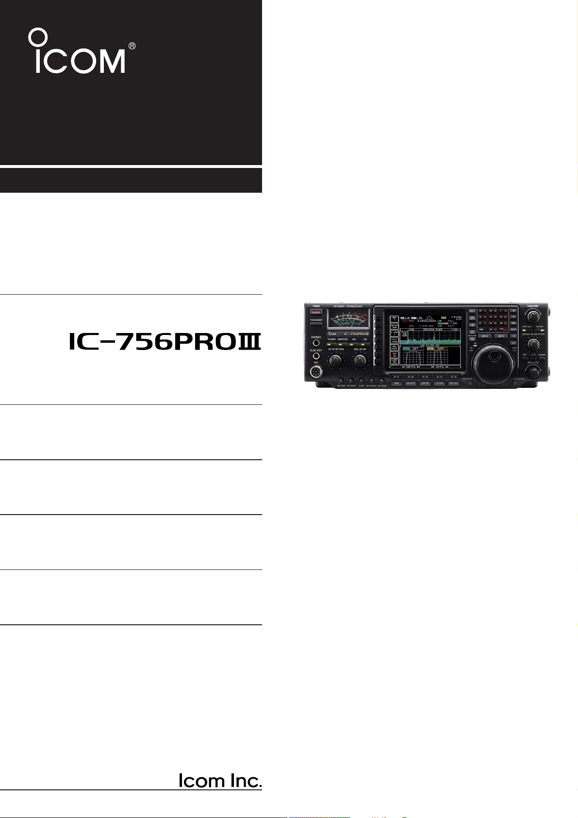
We understand that you have a choice of many different radios in the market place. We would like to take a
couple of moments of your time to thank you for making your IC-756PROIII your radio of choice, and hope
you agree with Icom’s philosophy of “technology first.”
Many hours of research and development went into
the design of your IC-756PROIII.
D
FEATURES
❍ +30 dBm class IP3 (at 14 MHz band) and
further improved 3rd order IMD characteristics
❍ Real time spectrum scope with mini-scope
function
❍ Boudot RTTY demodulator and RTTY
transmit message memory
❍ Selectable SSB transmission passband
width (Each for Higher and lower pass frequency)
❍ Digital IF filter allows you to select 51 types
of filter shapes while receiving a station
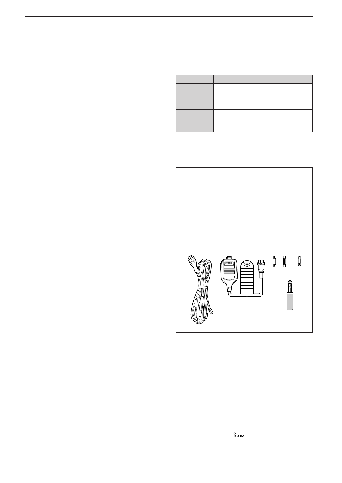
The transceiver comes with the following accessories.
Qty.
q DC power cable (OPC-025D) .......................... 1
w Hand microphone (HM-36) .............................. 1
e Spare fuses (FGB 30 A) .................................. 2
r Spare fuse (FGB 5 A) ...................................... 1
t CW keyer plug (AP-330) .................................. 1
qwe
r
t
Spurious may be received near the following frequencies.
These are made in the internal circuit and does not indicate a
transceiver malfunction:
6.144 MHz, 8.000 MHz,
12.288 MHz, 12.890 MHz (when spectrum scope is ON),
18.433 MHz, 24.573 MHz, 52 MHz
FOREWORD SUPPLIED ACCESSORIES
Page 3

ii
R WARNING RF EXPOSURE! This device
emits Radio Frequency (RF) energy. Extreme caution
should be observed when operating this device. If you
have any questions regarding RF exposure and safety
standards please refer to the Federal Communications
Commission Office of Engineering and Technology’s
report on Evaluating Compliance with FCC Guidelines
for Human Radio Frequency Electromagnetic Fields
(OET Bulletin 65).
R WARNING HIGH VOLTAGE! NEVER at-
tach an antenna or internal antenna connector during
transmission. This may result in an electrical shock or
burn.
RWARNING! NEVER operate the transceiver
with a headset or other audio accessories at high volume levels. Hearing experts advise against continuous
high volume operation. If you experience a ringing in
your ears, reduce the volume or discontinue use.
RCAUTION! NEVER change the internal settings
of the transceiver. This result in reduced transceiver
performance and/or damage to the transceiver.
In particular, incorrect settings for transmitter circuits,
such as output power, idling current, etc., might damage the expensive final devices.
The transceiver warranty does not cover any problems
caused by unauthorized internal adjustment.
R NEVER apply AC to the [DC13.8V] jack on the
transceiver rear panel. This could cause a fire or ruin
the transceiver.
RNEVER apply more than 16 V DC, such as a 24 V
battery, to the [DC13.8V] jack on the transceiver rear
panel. This could cause a fire or ruin the transceiver.
RNEVER let metal, wire or other objects touch any
internal part or connectors on the rear panel of the
transceiver. This may result in an electric shock.
R NEVER expose the transceiver to rain, snow or
any liquids.
RNEVER installing the transceiver in a place with-
out adequate ventilation. Heat dissipation may be affected, and the transceiver may be damaged.
RNEVER operate or touch the transceiver with wet
hands. This may result in an electric shock or damage
to the transceiver.
AVOID using or placing the transceiver in areas with
temperatures below –10°C (+14°F) or above +50°C
(+122°F). Be aware that temperatures on a vehicle’s
dashboard can exceed 80°C (+176°F), resulting in permanent damage to the transceiver if left there for extended periods.
AVOID placing the transceiver in excessively dusty environments or in direct sunlight.
AVOID placing the transceiver against walls or putting
anything on top of the transceiver. This will obstruct
heat dissipation.
Place unit in a secure place to avoid inadvertent use
by children.
During mobile operation, DO NOT operate the transceiver without running the vehicle’s engine. When
transceiver power is ON and your vehicle’s engine is
OFF, the vehicle’s battery will soon become exhausted.
Make sure the transceiver power is OFF before starting the vehicle. This will avoid possible damage to the
transceiver by ignition voltage spikes.
During maritime mobile operation, keep the transceiver
and microphone as far away as possible from the magnetic navigation compass to prevent erroneous indications.
BE CAREFUL! The heatsink will become hot when operating the transceiver continuously for long periods.
BE CAREFUL! If a linear amplifier is connected, set
the transceiver’s RF output power to less than the linear amplifier’s maximum input level, otherwise, the linear amplifier will be damaged.
The LCD display may have cosmetic imperfections
that appear as small or dark spots. This is not a malfunction or defect, but a normal characteristic of LCD
displays.
Use Icom microphones only (supplied or optional).
Other manufacturer’s microphones have different pin
assignments, and connection to the IC-756PROIII may
damage the transceiver.
For U.S.A. only
CAUTION: Changes or modifications to this device,
not expressly approved by Icom Inc., could void your
authority to operate this device under FCC regulations.
PRECAUTIONS
Page 4

iii
TABLE OF CONTENTS
IMPORTANT .................................................................. i
FOREWORD ................................................................. i
EXPLICIT DEFINITIONS ............................................... i
SUPPLIED ACCESSORIES .......................................... i
PRECAUTIONS ............................................................ ii
TABLE OF CONTENTS .............................................. iii
1PANEL DESCRIPTION ..................................... 1–12
■ Front panel ....................................................... 1
■ LCD display ..................................................... 9
■ Screen menu arrangement ............................ 10
■ Rear panel ...................................................... 11
■ Microphone (HM-36) ...................................... 12
2 INST ALLATION AND CONNECTIONS .......... 13–20
■ Unpacking ...................................................... 13
■ Selecting a location ........................................ 13
■ Grounding ...................................................... 13
■ Antenna connection ....................................... 13
■ Required connections .................................... 14
■ Advanced connections ................................... 15
■ Power supply connections ............................. 16
■ Linear amplifier connections .......................... 17
■ External antenna tuner
connections .................................................... 18
■ Transverter jack information .......................... 18
■ Microphone connector information ................ 18
■ FSK and AFSK (SSTV)
connections .................................................... 19
■ Accessory connector information ................... 20
3 BASIC OPERATION ....................................... 21–32
■ When first applying power
(CPU resetting) .............................................. 21
■ Initial settings ................................................. 21
■ VFO description ............................................. 22
■ Selecting VFO/memory mode ........................ 23
■ Main/Sub band selection ............................... 23
■ Selecting an operating band .......................... 24
DUsing the band stacking registers ............... 24
■ Frequency setting .......................................... 25
DTuning with the tuning dial ........................... 25
DDirect frequency entry with the keypad ....... 25
DQuick tuning step ......................................... 26
DSelecting “kHz” step .................................... 26
DSelecting 1 Hz step...................................... 27
D1⁄4 tuning function
(SSB data/CW/RTTY only) .......................... 27
DAuto tuning step function ............................. 28
DBand edge warning beep............................. 28
■ Operating mode selection .............................. 29
■ Volume setting ............................................... 29
■ Squelch and receive (RF) sensitivity ............. 30
■ Meter function ................................................ 31
■ SWR reading ................................................. 31
■ Basic transmit operation ................................ 32
DTransmitting ................................................. 32
DMicrophone gain adjustment ....................... 32
4 RECEIVE AND TRANSMIT ............................ 33–54
■ Operating SSB ............................................... 33
DConvenient functions for receive ................. 33
DConvenient functions for transmit ................ 34
DAbout 5 MHz band operation
(USA version only)....................................... 34
■ Operating CW ................................................ 35
DConvenient functions for receive ................. 35
DConvenient functions for transmit ................ 36
DAbout CW reverse mode ............................. 36
DCW side tone function ................................. 36
DAbout CW pitch control ................................ 37
■ Electronic CW keyer ...................................... 38
DMemory keyer send screen ......................... 39
DEditing a memory keyer ............................... 40
DContest number set mode ........................... 41
DKeyer set mode ........................................... 42
■ Operating RTTY (FSK) .................................. 44
DConvenient functions for receive ................. 44
DAbout RTTY reverse mode .......................... 45
DRTTY filter/Twin peak filter........................... 45
DFunctions for the RTTY decoder indication . 46
DSetting the decoder threshold level ............. 46
DRTTY memory transmission ........................ 47
DRTTY tuning meter ...................................... 47
DEditing RTTY memory ................................. 48
DRTTY decoder set mode.............................. 49
■ Operating AM ................................................. 50
DConvenient functions for receive ................. 50
DConvenient functions for transmit ................ 50
■ Operating FM ................................................. 51
DConvenient functions for receive ................. 51
DConvenient functions for transmit ................ 51
■ Repeater operation ........................................ 52
DSetting the repeater tone ............................. 52
■ Tone squelch operation .................................. 53
■ Data mode (SSTV/PSK31) operation ............ 54
5 FUNCTION FOR RECEIVE ............................ 55–65
■ Spectrum scope screen ................................. 55
DMini scope screen........................................ 55
DScope set mode........................................... 56
■ Preamplifier .................................................... 57
■ Attenuator ...................................................... 57
■ RIT function .................................................... 58
■ AGC function .................................................. 59
■ Twin PBT operation ........................................ 60
■ IF filter selection ............................................. 61
■ DSP filter shape.............................................. 62
■ Dualwatch operation ...................................... 63
■ Noise blanker ................................................. 64
■ Notch function ................................................ 64
■ Noise reduction .............................................. 65
■ Dial lock function ............................................ 65
Page 5

iv
TABLE OF CONTENTS
1
2
3
4
5
6
7
8
9
10
11
12
13
14
15
16
17
18
19
6 FUNCTION FOR TRANSMIT ......................... 66–72
■ VOX function .................................................. 66
DUsing the VOX function ............................... 66
DAdjusting the VOX function.......................... 66
■ Break-in function ............................................ 67
DSemi break-in operation .............................. 67
DFull break-in operation ................................. 67
■ Transmit filter width setting (SSB only) .......... 68
■ Speech compressor ....................................... 68
■ ∂TX function .................................................. 69
■ Monitor function ............................................. 70
■ Split frequency operation ............................... 71
■ Quick split function ......................................... 72
7 VOICE RECORDER FUNCTIONS ................. 73–76
■ Digital voice recorder ..................................... 73
8 MEMORY OPERATION .................................. 77 – 82
■ Memory channels .......................................... 77
■ Memory channel selection ............................. 77
■ Memory channel screen ................................ 78
■ Memory channel programming ...................... 79
■ Frequency transferring ................................... 80
■ Memory names .............................................. 81
■ Memory clearing ............................................ 81
■ Memo pads .................................................... 82
9 SCANS ........................................................... 83–87
■ Scan types ..................................................... 83
■ Preparation .................................................... 83
■ Programmed scan operation ......................... 84
■ ∂F scan operation ......................................... 84
■ Fine programmed scan/
fine ∂F scan ................................................... 85
■ Memory scan operation ................................. 85
■ Select memory scan operation ...................... 86
■ Setting select memory channels .................... 86
■ Scan set mode ............................................... 87
■ Tone scan ....................................................... 87
10 ANTENNA TUNER OPERATION ................... 88–90
■ Automatic antenna selection .......................... 88
■ Antenna tuner operation ................................ 89
■ Optional external tuner operation .................. 90
11 CLOCK AND TIMERS .................................... 91–93
■ Time set mode ............................................... 91
DSetting the current time ............................... 92
DClock2 function activity ................................ 92
DClock2 offset setting .................................... 92
DTimer function activity .................................. 92
DSetting power-on time.................................. 93
DSetting power-off period............................... 93
DTimer operation............................................ 93
12 SET MODE ................................................... 94–104
■ Set mode description ..................................... 94
■ Level set mode .............................................. 95
■ Display set mode ........................................... 97
■ DSP filter set mode......................................... 99
■ Miscellaneous (others) set mode ................... 99
13 OPTION INSTALLATION .................................... 105
■ Opening the transceiver’s case ................... 105
■ UT-102
VOICE SYNTHESIZER UNIT
.................. 105
14 INTERNAL VIEWS .............................................. 106
15 MAINTENANCE ......................................... 107–109
■ Troubleshooting ........................................... 107
■ Fuse replacement ........................................ 108
■ Clock backup battery
replacement ................................................. 108
■ Tuning dial brake adjustment ....................... 109
■ Frequency calibration
(approximate)................................................ 109
16 CONTROL COMMAND ............................... 110– 114
■ Remote jack (CI-V) information .................... 110
17 SPECIFICATIONS ............................................... 115
18 OPTIONS ............................................................. 116
19 ABOUT CE ........................................................... 117
Page 6
1
1
PANEL DESCRIPTION
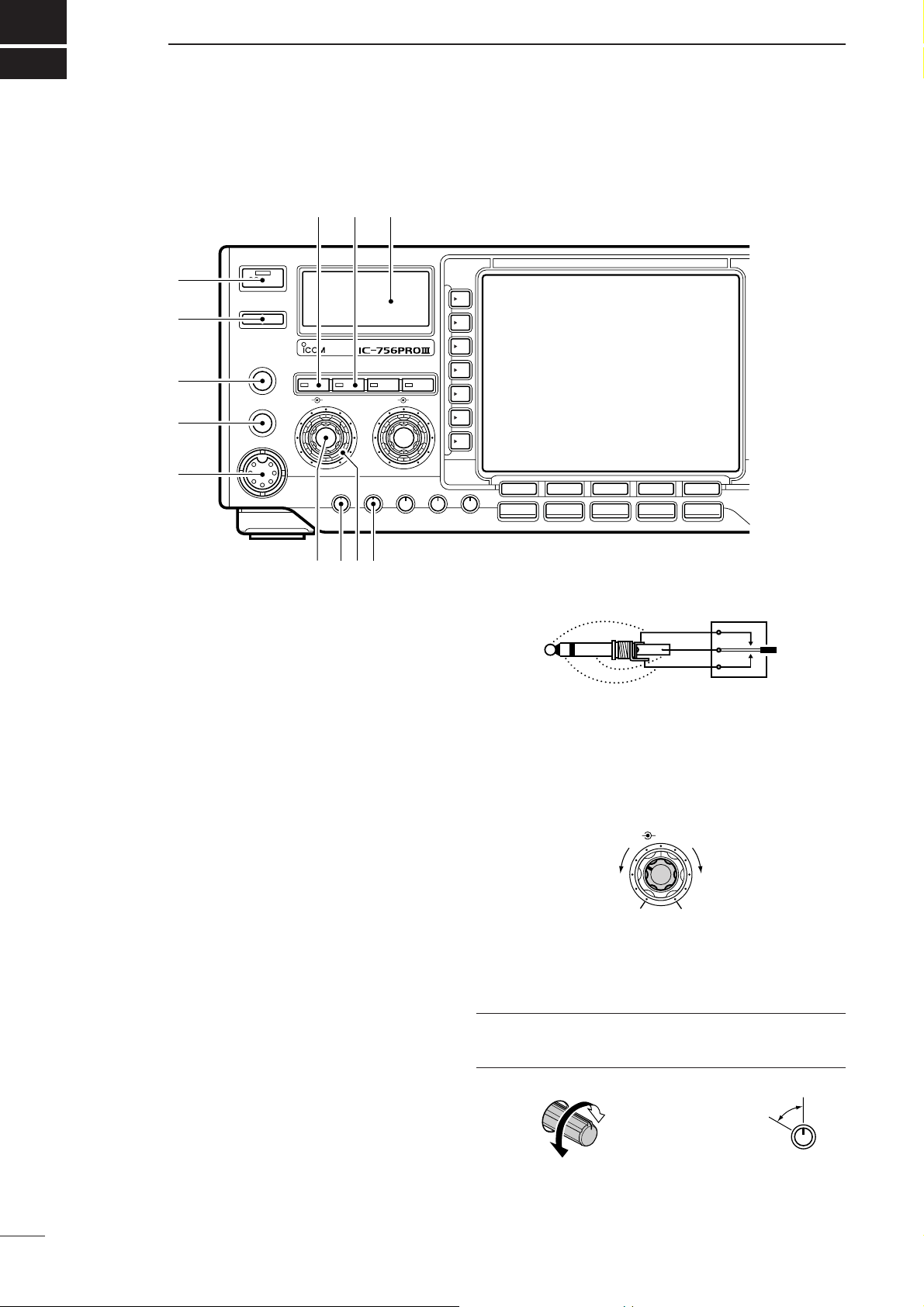
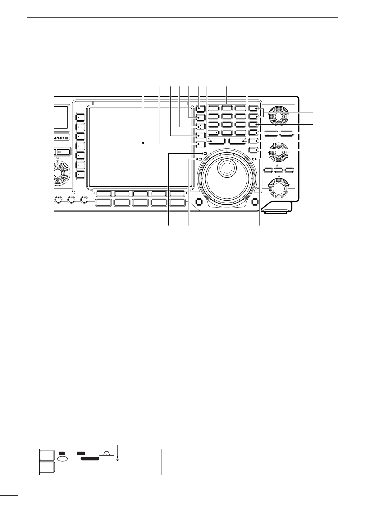
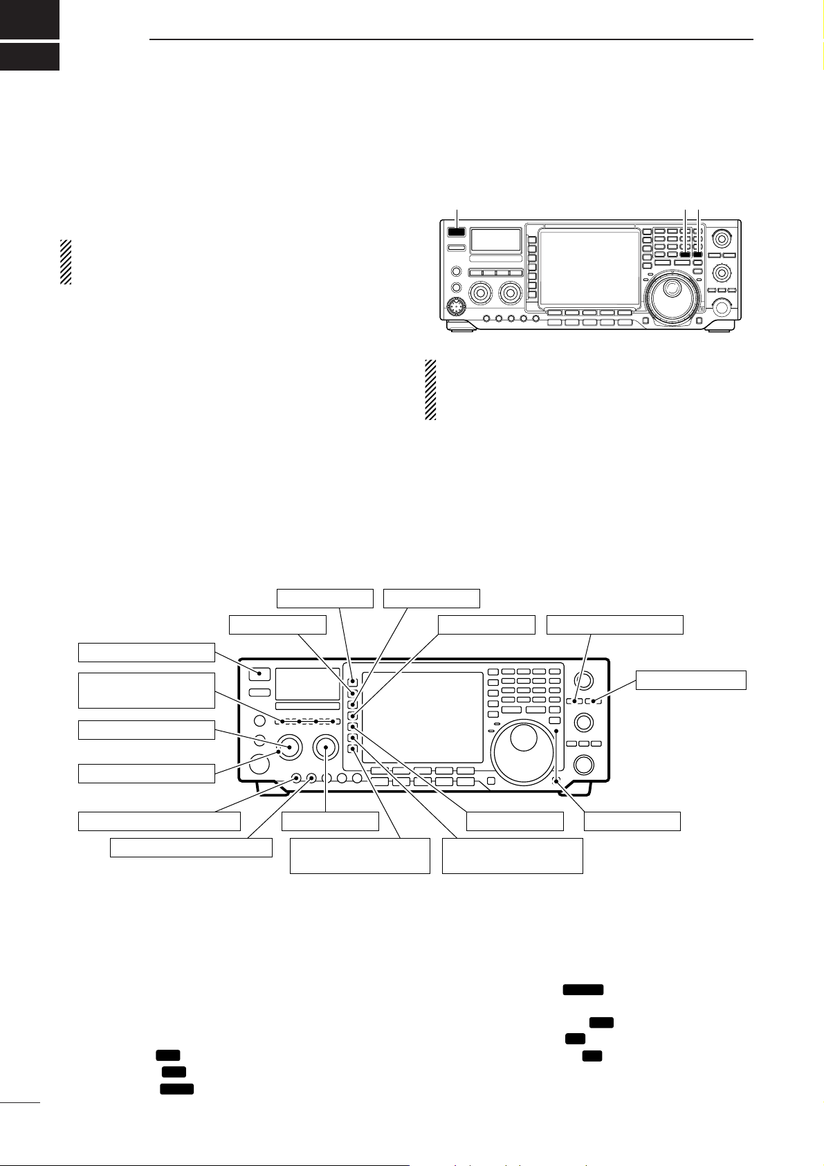
■ Front panel
q POWER SWITCH [POWER•TIMER]
❍ While transceiver’s power is OFF:
Push to turn power ON.
•Turn the optional DC power supply ON in advance.
•A/D converter calibration of the DSP unit starts and it
takes approx. 10 sec.
❍ While transceiver’s power is ON:
➥ Push momentarily to toggle the timer function
ON and OFF. (p. 93)
•The [TIMER] indicator in this switch lights while
the timer function is ON.
➥ Push for 1 sec. to turn power OFF.
w TRANSMIT SWITCH [TRANSMIT]
Selects transmitting or receiving.
•The [TX] indicator lights red while transmitting and the
[RX] indicator lights green when the squelch is open.
e HEADPHONE JACK [PHONES]
Accepts headphones.
• Output power: 5 mW with an 8 Ω load.
•When headphones are connected, the internal speaker
or connected external speaker does not function.
r ELECTRONIC KEYER JACK [ELEC-KEY]
Accepts a paddle to activate the internal electronic
keyer for CW operation. (p. 38)
•Selection between the internal electronic keyer, bug-key
and straight key operation can be made in keyer set
mode. (p. 43)
•A straight key jack is separately available on the rear
panel. See [KEY] on p. 11.
•Keyer polarity (dot and dash) can be reversed in keyer
set mode. (p. 43)
•4-channel memory keyer is available for your convenience. (p. 40)
t MICROPHONE CONNECTOR [MIC]
Accepts the supplied or optional microphone.
•See p. 116 for appropriate microphones.
•See p. 18 for microphone connector information.
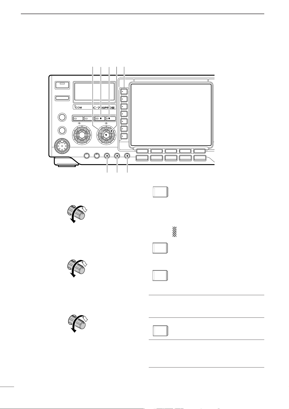
y AF CONTROL [AF] (inner control)
Varies the audio output level from the speaker.
u MIC GAIN CONTROL [MIC GAIN]
Adjusts microphone input gain.
•The transmit audio tone in SSB mode can be adjusted in
set mode. (p. 95)
✔
How to set the microphone gain.
Set the [MIC] control so that the ALC meter sometimes
swings during normal voice level transmission in SSB mode.
MIC GAIN
Recommended level for
an Icom microphone
Increases
Decreases
MIC GAIN
AF RF/SQL
No audio output
Max. audio output
Decreases Increases
(dot)
(com)
(dash)
!0!1!2
q
TIMER
POWER
TRANSMIT
HF/50MHz TRANSCEIVER
w
PHONES
TUNER MONITOR NB NR
e
ELEC-KEY
AF BAL NRRF/SQL
r
MIC
t
MIC GAIN RF POWER COMP BK-IN DELAY KEY SPEED
yiou
F-1 F-2 F-3 F-4 F-5
SSB
CW/RTTY
AM/FM FILTER EXIT/SET
Page 7
2
1
PANEL DESCRIPTION
1
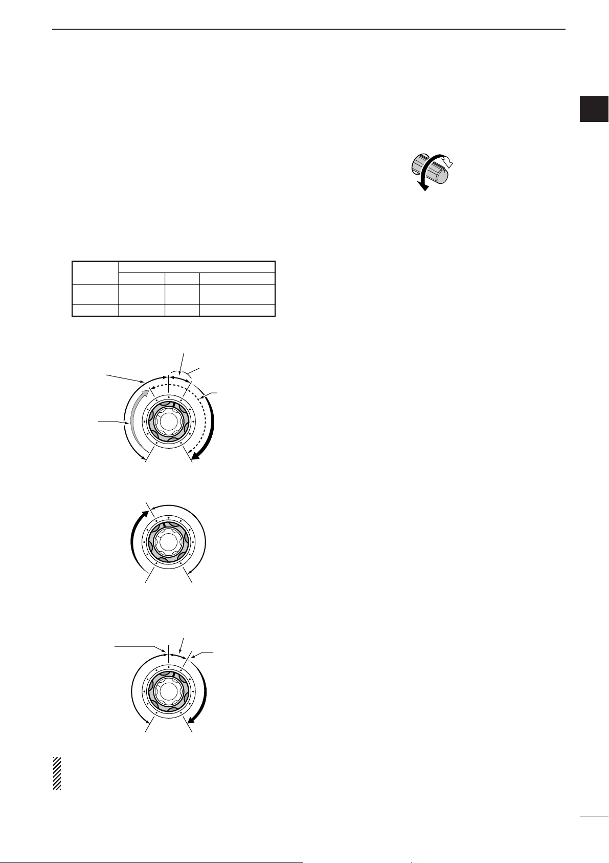
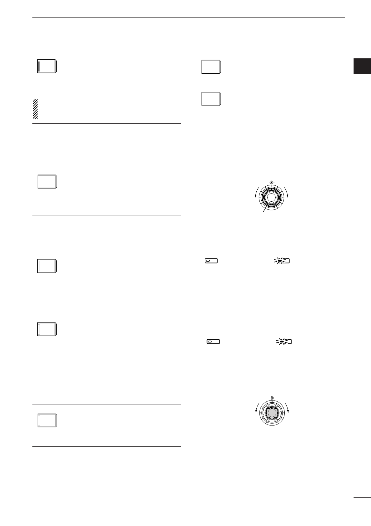
i RF GAIN CONTROL/SQUELCH CONTROL
[RF/SQL] (outer control)
Adjusts the RF gain and squelch threshold level.
The squelch removes noise output from the
speaker (closed condition) when no signal is received.
•The squelch is particularly effective for FM. It is also
available for other modes.
•12 to 1 o’clock position is recommended for any setting
of the [RF/SQL] control.
•The control can be set as ‘Auto’ (RF gain control in SSB,
CW and RTTY; squelch control in AM and FM) or
squelch control (RF gain is fixed at maximum) in set
mode as follows. (p. 99)
•When setting as RF gain/squelch control
•When functioning as RF gain control
(Squelch is fixed open; SSB, CW, RTTY only)
•When functioning as squelch control
(RF gain is fixed at maximum.)
While rotating the RF gain control, noise may be
heard. This comes from the DSP unit and does not
indicate an equipment malfunction.
o RF POWER CONTROL [RF POWER]
Continuously varies the RF output power from minimum
(5 W*) to maximum (100 W*).
* AM mode: 5 W to 40 W
!0 S/RF METER (p. 31)
Shows the signal strength while receiving. Shows
the relative output power, SWR, ALC or compression levels while transmitting.
!1 MONITOR SWITCH [MONITOR] (p. 70)
Monitors your transmitted IF signal.
•The CW side tone functions regardless of the [MONI-
TOR] switch setting in CW mode.
•The [MONITOR] indicator in this switch lights green
when the function is activated.
!2 ANTENNA TUNER SWITCH [TUNER] (p. 89)
➥ Turns the internal antenna tuner ON and OFF
(bypass)
when pushed momentarily.
➥ Tunes the antenna manually when pushed for 1
sec.
•The [TUNER] indicator in this switch lights red when
the function is activated or blinks during manual tuning.
•When the tuner cannot tune the antenna, the tuning
circuit is bypassed automatically after 20 sec.
Increases
max. 100 W
(40 W for AM)
Decreases
min. 5 W
RF POWER
MODE
SSB, CW
RTTY
AM, FM
RF GAIN
SET MODE SETTING
AUTO
SQL
SQL
SQL
SQL
RF GAIN + SQL
RF GAIN + SQL
RF GAIN + SQL
Noise squelch (FM mode)
Squelch is
open.
RF gain
adjustable
range
Recommended level
Maximum
RF gain
S-meter
squelch
Maximum
RF gain
Adjustable
range
Minimum RF gain
Noise squelch
threshold
(FM mode)
Squelch is
open.
Noise squelch (FM mode)
S-meter squelch
threshold
S-meter
squelch
Shallow Deep
Page 8
3
1
PANEL DESCRIPTION
■ Front panel (continued)
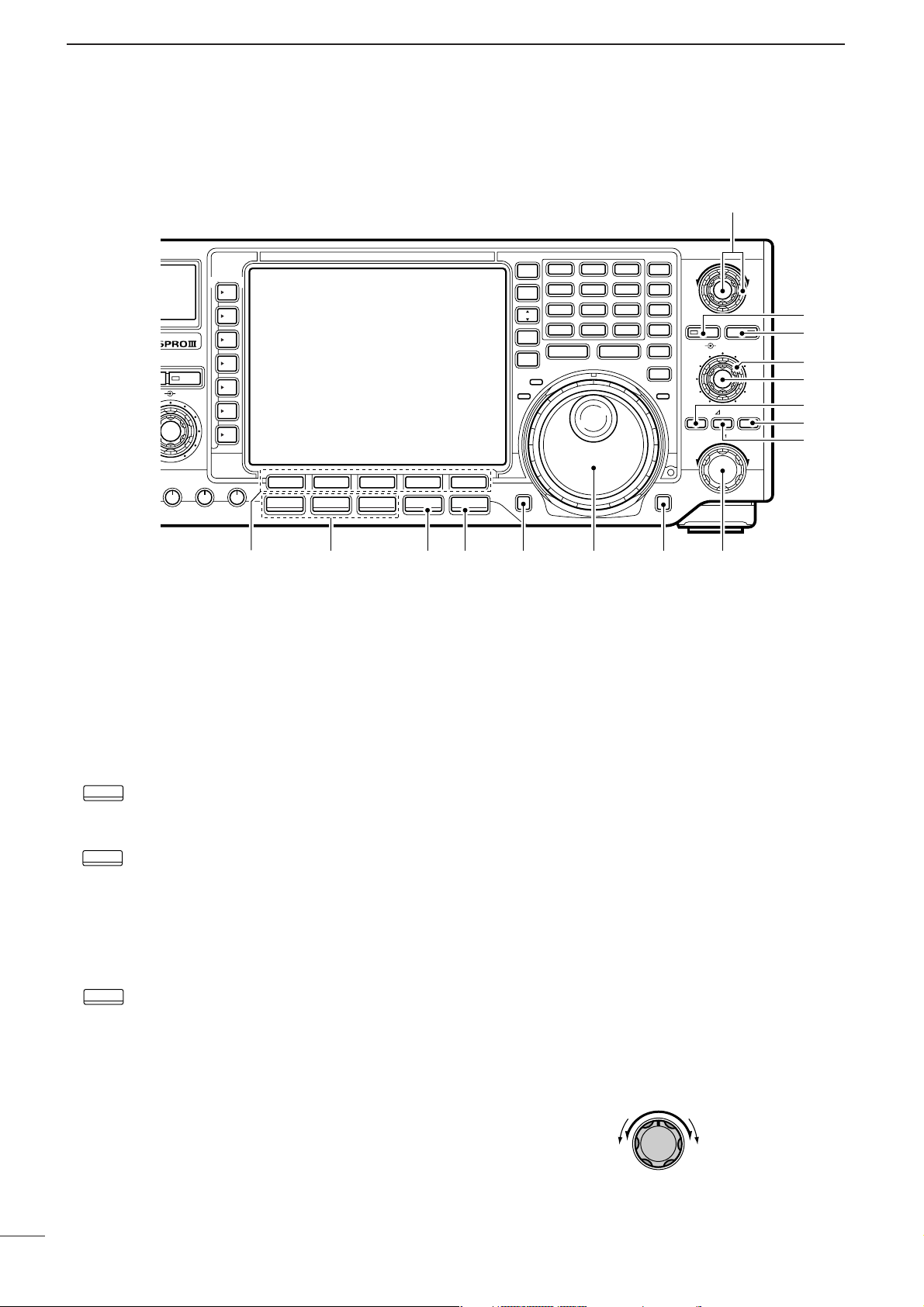
!3 COMPRESSION LEVEL CONTROL [COMP]
(p. 68)
Adjusts the speech compression level in SSB.
!4 SEMI BREAK-IN DELAY CONTROL
[BK-IN DELAY]
Adjusts the transmit-to-receive switching delay time
for CW semi break-in operation.
!5 ELECTRONIC CW KEYER SPEED CONTROL
[KEY SPEED] (p. 35)
Adjusts the internal electronic CW keyer’s speed.
•6 wpm (min.) to 60 wpm (max.) can be set.
!6 MULTI-FUNCTION SWITCHES
Push to select the functions indicated in the LCD
display to the right of these switches.
•Functions vary depending on the operating condition.
➥ Selects the antenna connector between
ANT1 and ANT2 when pushed. (p. 88)
➥ Turns the [RX ANT] (receive antenna) ON
and OFF when pushed for 1 sec.
•When the receive antenna is activated, the
antenna which is connected to the [ANT1] or
[ANT2] is used for transmission only.
When a transverter is in use, this [ANT]
does not function and ‘XVERT’ appears.
➥ Selects RF power
(Po), SWR, ALC or
COMP metering during transmit. (p. 31)
➥ Switches the multi-function digital meter
ON and OFF when pushed for 1 sec.
➥ Selects one of 2 receive RF preamps or
bypasses them. (p. 57)
•“P. AMP1” activates 10 dB preamp.
•“P. AMP2” activates 16 dB high-gain preamp.
✔
What is the preamp?
The preamp amplifies received signals in the front end circuit to improve the S/N ratio and increase the sensitivity. Select “P. AMP1” or “P. AMP2” when receiving weak signals.
➥ Selects 6 dB, 12 dB or 18 dB attenuator,
or bypasses them. (p. 57)
✔
What is the attenuator?
The attenuator prevents a desired signal from distorting
when very strong signals are near the desired frequency, or
when very strong electric fields, such as from a broadcasting station, are near your location.
ATT
OFF
P.AMP
OFF
METER
Po
ANT
!6!7!8@0 !9
TIMER
POWER
TRANSMIT
PHONES
ELEC-KEY
MIC
HF/50MHz TRANSCEIVER
TUNER MONITOR NB NR
AF BAL NRRF/SQL
MIC GAIN RF POWER COMP BK-IN DELAY KEY SPEED
!5!4!3
Compression
Compression
level decreases
level increases
COMP
Long delay for
slow speed keying
Short delay for
high speed keying
(2 dot)
BK-IN DELAY
(13 dot)
Fast
Slow
KEY SPEED
F-1 F-2 F-3 F-4 F-5
SSB
CW/RTTY
AM/FM FILTER EXIT/SET
ANT
1
METER
Po
P.AMP
OFF
ATT
OFF
Page 9
4
1
PANEL DESCRIPTION
1
➥ Activates or selects fast, middle or slow
AGC time constant when pushed. (p. 59)
•“FAST” is only available for FM mode.
➥ Enters the AGC set mode when pushed
for 1 sec. (p. 59)
AGC time constant can be set between 0.1 to
8.0 sec.
(depends on mode), or turned OFF. While
“OFF” is selected, the S-meter does not function.
✔
What is the AGC?
The AGC function controls receiver gain to produce a constant audio output level, even when the received signal
strength is varied by fading, etc. Select “FAST” for tuning and
select “MID” or “SLOW” depending on the receiving condition.
➥ Turns the VOX function ON and OFF
when pushed in a phone mode (SSB, AM
or FM mode). (p. 66)
➥ Enters the VOX set mode when pushed
for 1 sec. in a phone mode. (p. 66)
✔
What is the VOX function?
The VOX function (voice operated transmission) starts transmission without pushing the transmit switch or PTT switch
when you speak into the microphone; then, automatically returns to receive when you stop speaking.
➥ Selects semi break-in, full break-in oper-
ation, or turns the break-in operation
OFF when pushed in CW mode. (p. 67)
✔
What is the break-in function?
The break-in function switches transmit and receive with CW
keying. Full break-in function (QSK) can monitor the receive
signal during keying.
➥ Turns the RTTY filter ON and OFF in
RTTY mode. (p. 45)
•When the RTTY filter is turned ON, [TWIN
PBT] functions as the IF shift control.
➥ Enters the RTTY filter set mode when
pushed for 1 sec. in RTTY mode. (p. 45)
✔
What is the IF shift?
The IF shift function electronically changes the center of the
IF (Intermediate Frequency) passband frequency to reject interference. Only the inner control of [TWIN PBT] can be
used for the IF shift control.
➥ Turns the speech compressor ON and
OFF in SSB mode. (p. 68)
➥ Switches the narrow, middle or wide
transmit filter when pushed for 1 sec.
✔
What is the speech compressor?
The speech compressor compresses the transmitter audio
input to increase the average audio output level. Therefore,
talk power is increased. This function is effective for long distance communication or when propagation conditions are
poor.
➥ Turns the 1⁄4 function ON and OFF in
SSB data, CW and RTTY modes. (p. 27)
•1⁄4 function sets dial rotation to 1⁄4 of normal
for fine tuning.
➥ Switches the tone encoder, tone squelch
function and no tone operation when
pushed in FM mode. (pgs. 52, 53)
➥ Enters the tone set mode when pushed
for 1 sec. in FM mode. (pgs. 52, 53)
!7 NOISE REDUCTION LEVEL CONTROL [NR]
(outer control; p. 65)
Adjusts the noise reduction level when the noise reduction is in use. Set for maximum readability.
•To activate this control, turn the noise reduction ON in
advance (!8).
!8 NOISE REDUCTION SWITCH [NR] (p. 65)
Push to switch the noise reduction ON and OFF.
•The [NR] indicator in this switch lights green when the
function is activated.
!9 NOISE BLANKER SWITCH [NB] (p. 64)
➥ Switches the noise blanker ON and OFF when
pushed. The noise blanker reduces pulse-type
noise such as that generated by automobile ignition systems. This function cannot be used for
FM mode, or non-pulse-type noise.
•The [NB] indicator in this switch lights green when the
function is activated.
➥ Enters the noise blanker level set mode when
pushed for 1 sec.
@0 BALANCE CONTROL [BAL] (inner control; p. 63)
Adjusts the audio output balance between main and
sub readout frequencies while in dualwatch.
BAL NR
Increases main
readout gain
Increases sub
readout gain
Noise blanker OFF Noise blanker ON
NB NB
Noise reduction OFF Noise reduction ON
NR NR
BAL NR
Decreases
OFF
Increases
TONE
OFF
1/4
OFF
COMP
OFF
WIDE
RTTY
FIL
OFF
BK-IN
OFF
VOX
OFF
AGC
MID
AGC
MID
VOX
OFF
1/4
OFF
TONE
OFF
BK-IN
OFF
RTTY
FIL
OFF
COMP
WIDE
OFF
Page 10
5
1
PANEL DESCRIPTION
■ Front panel (continued)
@1 LCD FUNCTION SWITCHES [F-1]–[F-5]
Push to select the function indicated in the LCD display above these switches.
• Functions vary depending on the operating condition.
@2 MODE SWITCHES
Selects the desired mode. (p. 29)
•Announces the selected mode when an optional UT-102
is installed. (pgs. 102, 105)
➥ Selects USB and LSB mode alternately.
➥ Selects SSB data mode (USB-D, LSB-D)
when pushed for 1 sec. in SSB mode.
➥ Selects CW and RTTY mode alternately.
➥ Switches CW and CW-R
(CW reverse)
mode when pushed for 1 sec. in CW
mode.
➥ Switches RTTY and RTTY-R (RTTY re-
verse)
mode when pushed for 1 sec. in
RTTY mode.
➥ Selects AM and FM mode alternately.
➥ Selects AM/FM data mode
(AM-D, FM-D)
when pushed for 1 sec. in AM or FM
mode.
@3 FILTER SWITCH [FILTER] (p. 61)
➥ Push to select one of 3 IF filter settings.
➥ Push for 1 sec. to enter the filter set mode.
@4 EXIT/SET SWITCH [EXIT/SET]
➥ Push to exit from a set mode, etc.
➥ Push for 1 sec. to enter the set mode screen.
(p. 94)
@5 REC/PLAY SWITCH [REC/PLAY] (p. 73)
➥ Push momentarily to playback the recorded con-
tents in the channel R4 of the voice memory.
➥ Push for 1 sec. to record the receiving signal con-
tents into the channel R4
(max. 15 sec.) of the
voice memory.
@6 TUNING DIAL (p. 25)
Changes the displayed frequency, selects set mode
settings, etc.
@7 LOCK/SPEECH SWITCH [LOCK/SPEECH]
➥ Push momentarily to toggle the dial lock function
ON and OFF. (p. 65)
➥ Push for 1 sec. to announce the S-meter indica-
tion and the selected readout frequency when an
optional UT-102 is installed. (p. 105)
@8 RIT/∂∂TX CONTROL [RIT/∂∂TX] (pgs. 58, 69)
Shifts the receive and/or transmit frequency without
changing the transmit and/or receive frequency
while the RIT and/or ∂TX functions are ON.
•Rotate the control clockwise to increase the frequency,
or rotate the control counterclockwise to decrease the
frequency.
•The shift frequency range is ±9.999 kHz in 1 Hz steps
(or ±9.99 kHz in 10 Hz steps).
RIT/∂TX
Low shift High shift
#6
EIVER
NB NR
BAL NR
F-1 F-2 F-3 F-4 F-5
SSB
COMP BK-IN DELAY KEY SPEED
CW/RTTY
@1
AM/FM FILTER EXIT/SET
@2 @4@3 @5 @6
SSB
CW/RTTY
AM/FM
TWIN PBT
1.8 3.5 7
SPLIT
WATCH
CHANGE
MEMO
M.SCOPE
REC/PLAY
DUAL
VFO/
MAIN/
10 14 18
21 24 28
GENE
SUB
RX
123
456
789
50
•
0
MP-W MP-R
Y
Z
MW
M-CL
TS
XFC
LOCKTX
LOCK/SPEECH
@7
PBT CLR NOTCH
NOTCH
CW PITCH
TXRIT CLEAR
RIT/ TX
@8
F-INP
ENT
#5
#4
#3
#2
#1
#0
@9
Page 11
6
1
PANEL DESCRIPTION
1
@9
∂∂
TX SWITCH [∂∂TX] (p. 69)
➥ Turns the ∂TX function ON and OFF when
pushed.
•Use the [RIT/∂∂TX] control to vary the ∂TX frequency.
➥ Adds the ∂TX shift frequency to the operating
frequency when pushed for 1 sec.
✔
What is the ∂∂TX function?
The ∂TX shifts the transmit frequency without shifting the receive frequency. This is useful for simple split frequency operation in CW, etc.
#0 CLEAR SWITCH [CLEAR] (pgs. 58, 69)
Clears the RIT/∂TX shift frequency when pushed
for 1 sec. (default).
•The response time (for 1 sec. or momentarily) can be
selected on the quick RIT/∂TX clear setting (p. 103).
#1 RIT SWITCH [RIT] (p. 58)
➥ Turns the RIT function ON and OFF when
pushed.
• Use the [RIT/∂∂TX] control to vary the RIT frequency.
➥ Adds the RIT shift frequency to the operating fre-
quency when pushed for 1 sec.
✔
What is the RIT function?
The RIT (Receiver Incremental Tuning) shifts the receive frequency without shifting the transmit frequency.
This is useful for fine tuning stations calling you on an off-frequency or when you prefer to listen to slightly differentsounding voice characteristics, etc.
#2 MANUAL NOTCH FILTER CONTROL [NOTCH]
(inner control; p. 64)
Varies the peak frequency of the manual notch fil-
ter to pick out a receive signal from interference
while the manual notch function is ON.
• Notch filter center frequency:
SSB : 0 Hz to 5100 Hz
CW : CW pitch freq.–900 Hz to CW pitch freq.
+4200 Hz
AM : –5100 Hz to 5100 Hz
#3 CW PITCH CONTROL [CW PITCH]
(outer control; p. 37)
Shifts the received CW audio pitch and monitored
CW audio pitch without changing the operating frequency.
#4 NOTCH SWITCH [NOTCH] (p. 64)
➥ Switches the notch function between auto, man-
ual and OFF in SSB and AM modes.
➥ Turns the manual notch function ON and OFF
when pushed in CW mode.
➥ Turns the auto notch function ON and OFF when
pushed in FM mode.
•“AN” appears on the display when auto notch is in
use.
•“MN” appears on the display when manual notch is in
use.
•The [NOTCH] indicator in this switch lights green
when the function is activated.
✔
What is the notch function?
The notch function eliminates unwanted CW or AM carrier
tones while preserving the desired signal’s audio response.
The filtering frequency is adjusted to effectively eliminate unwanted tones via the DSP circuit.
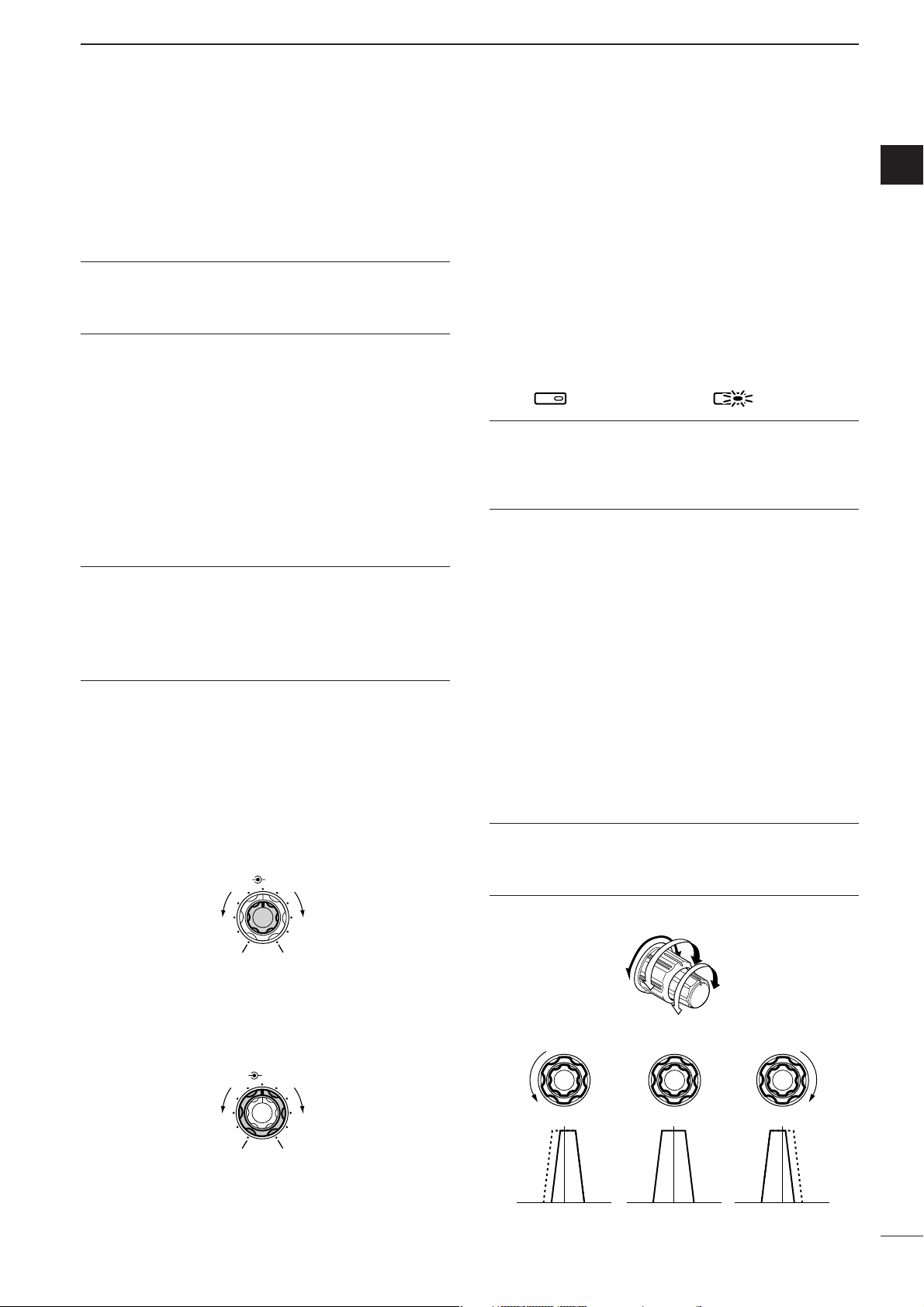
#5 PBT CLEAR SWITCH [PBT CLR] (p. 60)
Clears the PBT settings when pushed for 1 sec.
•The [PBT CLR] indicator in this switch lights green when
PBT is in use.
#6 PASSBAND TUNING CONTROLS [TWIN PBT]
Adjust the receiver’s “passband width” of the DSP
filter. (p. 60)
•Passband width and shift frequency are displayed in the
LCD.
•Push [PBT CLR] for 1 sec. to clear the settings when
not in use.
•Variable range is set to half of the IF filter passband
width. 25 Hz steps and 50 Hz steps are available.
•These controls function as an IF shift control while in AM
mode and when the RTTY filter is turned ON. Only the
inner control may function in this case.
✔
What is the PBT control?
General PBT function electronically narrows the IF passband
width to reject interference. This transceiver uses the DSP
circuit for the PBT function.
Low cut High cutCenter
TWIN PBT TWIN PBT TWIN PBT
–+
PBT1
PBT2
TWIN PBT
NOTCHNOTCH
Notch OFF Notch ON
Approx. 300 Hz
Approx. 900 Hz
Lower frequency Higher frequency
NOTCH CW PITCH
NOTCH CW PITCH
Lower frequency Higher frequency
Page 12
7
1
PANEL DESCRIPTION
■ Front panel (continued)
#7 RECEIVE INDICATOR [RX]
Lights green while receiving a signal and when the
squelch is open.
#8 TRANSMIT INDICATOR [TX]
Lights red while transmitting.
#9 LOCK INDICATOR [LOCK] (p. 65)
Lights red when the dial lock function is activated.
$0 TRANSMIT FREQUENCY CHECK SWITCH
[XFC]
Monitors the transmit frequency when pushed and
held during the split frequency operation.
•While pushing this switch, the transmit frequency can be
changed with the tuning dial, keypad, memo pad or the
[YY]/[ZZ] switches.
•When the split lock function is turned ON, pushing [XFC]
cancels the dial lock function. (p. 100)
$1 QUICK TUNING SWITCH [TS] (p. 26)
➥ Turns the quick tuning step ON and OFF.
•While the quick tuning indicator, “Z,” is displayed
above the frequency indication, the frequency can be
changed in programmed kHz steps.
•0.1, 1, 5, 9, 10, 12.5, 20 and 25 kHz quick tuning
steps are available for each operating mode independently.
➥ When the quick tuning step is OFF, push for 1
sec. to turn the 1 Hz tuning step ON and OFF.
•1 Hz indications appear in both readouts and the frequency can be changed in 1 Hz steps.
➥ When the quick tuning step is ON, push for 1 sec.
to enter the quick tuning step set mode.
$2 MEMORY CLEAR SWITCH [M-CL] (p. 81)
Clears the selected readout memory channel contents when pushed for 1 sec. in memory mode.
• The channel becomes a blank channel.
• This switch does not function in VFO mode.
$3 MEMORY WRITE SWITCH [MW] (p. 79)
Stores the selected readout frequency and operating mode into the displayed memory channel when
pushed for 1 sec.
•This function is available both in VFO and memory
modes.
$4 MEMORY UP/DOWN SWITCHES [YY]/[ZZ] (p. 77)
➥ Push to select the memory channel number for
the selected readout.
•Memory channels can be selected both in VFO and
memory modes.
➥ Select the desired memory channel directly after
pushing [(F-INP)ENT] and a memory channel
number.
$5 MEMO PAD-READ SWITCH [MP-R] (p. 82)
Each pushing calls up a frequency and operating
mode in a memo pad. The 5 (or 10) most recently
programmed frequencies and operating modes can
be recalled, starting from the most recent.
•The memo pad capacity can be expanded from 5 to 10
in set mode for your convenience. (p. 102)
BWBW
2.4k2.4k
SFTSFT
0
FIL2FIL2
TXTX
CWCW
qr.qpp.pp
21.076.5021.076.50
VFOVFO
USBUSB
1
METER
Po
ANT
1
qw:pp
12:0012:00
Quick tuning indicator
%3
CEIVER
NB NR
BAL NR
F-1 F-2 F-3 F-4 F-5
SSB
COMP BK-IN DELAY KEY SPEED
CW/RTTY
AM/FM FILTER EXIT/SET
%2 %1 $7
SPLIT
DUAL
WATCH
CHANGE
VFO/
MEMO
M.SCOPE
MAIN/
SUB
RX
REC/PLAY
$6$9%0 $8
1.813.527
10414518
21724828
GENE
50
0
MP-W MP-R
F-INP
#7 #8 #9
3
6
9
ENT
$5
Y
Z
MW
M-CL
TS
XFC
LOCKTX
LOCK/SPEECH
TWIN PBT
PBT CLR NOTCH
NOTCH
CW PITCH
TXRIT CLEAR
RIT/ TX
$4
$3
$2
$1
$0
Page 13

8
1
PANEL DESCRIPTION
$6 KEYPAD
➥ Pushing a key selects the operating band.
•[(GENE)•] selects the general coverage band.
➥ Pushing the same key 2 or 3 times calls up other
stacked frequencies in the band. (p. 24)
•Icom’s triple band stacking register memorizes 3 frequencies in each band.
➥ After pushing [(F-INP)ENT], enters a keyed fre-
quency or memory channel. Pushing [(F-
INP)ENT] or [YY]/[ZZ] is necessary at the end.
(pgs. 25, 77)
•e.g. to enter 14.195 MHz, push [(F-INP)ENT] [1] [4]
[•] [1] [9] [5] [(F-INP)ENT].
$7 MEMO PAD-WRITE SWITCH [MP-W] (p. 82)
Programs the selected readout frequency and operating mode into a memo pad.
•The 5 most recent entries remain in memo pads.
•The transmit frequency is programmed when pushed to-
gether with [XFC].
•The memo pad capacity can be expanded from 5 to 10
in set mode for your convenience. (p. 102)
$8 SPLIT SWITCH [SPLIT] (p. 71)
➥ Turns the split function ON and OFF when
pushed.
➥ Turns the split function ON, equalizes the sub
readout frequency to the main readout and sets
the sub readout for frequency input when pushed
for 1 sec. in non-FM modes.
(Quick split function)
•The offset frequency is shifted from the main readout
frequency in FM mode. (pgs. 52, 100)
•The quick split function can be turned OFF using set
mode. (p. 100)
➥ Turns the split function ON and shifts the sub
readout frequency after input an offset (±4 MHz
in 1 kHz steps).
$9 DUALWATCH SWITCH [DUALWATCH] (p. 63)
➥ Turns the dualwatch function ON and OFF when
pushed.
➥ Turns the dualwatch function ON and equalizes
the sub readout frequency to the main readout
when pushed for 1 sec. (Quick dualwatch function)
•The quick dualwatch function can be turned OFF
using set mode. (p. 98)
%0 MAIN/SUB CHANGE SWITCH [CHANGE]
➥ Switches the frequency and selected memory
channel between main and sub readouts when
pushed.
•Switches between transmit frequency and receive frequency when the split frequency function is ON.
(p. 71)
➥ Equalizes the sub readout frequency to the main
readout frequency when pushed for 1 sec.
%1 VFO/MEMORY SWITCH [VFO/MEMO]
➥ Switches the selected readout operating mode
between the VFO mode and memory mode when
pushed. (pgs. 23, 77)
➥ Transfers the memory contents to VFO when
pushed for 1 sec. (p. 80)
%2 MAIN/SUB•M.SCOPE SWITCH
[MAIN/SUB•M.SCOPE]
➥ Push momentarily to select access to the main or
sub readout. (p. 23)
•The sub readout frequency is displayed in outline or
mesh font. The sub readout functions only during split
operation or dualwatch.
➥ Push for 1 sec. to turn the mini spectrum scope
screen indication ON and OFF. (p. 55)
•The mini spectrum scope screen can be indicated
with another screen, such as memory, set mode
screen, simultaneously.
%3 LCD FUNCTION DISPLAY (See p. 9 for details.)
Shows the operating frequency, function switch
menus, spectrum scope screen, memory channel
screen, set mode settings, etc.
1
Page 14
9
1
PANEL DESCRIPTION
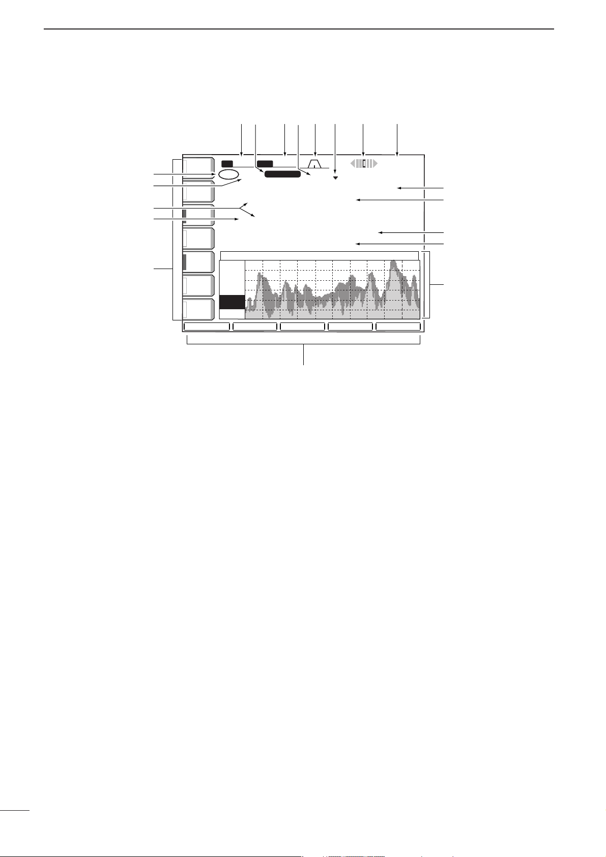
■ LCD display
q TX INDICATOR
Indicates the frequency readout for transmission.
w VFO/MEMORY CHANNEL INDICATOR
(pgs. 23, 77)
Indicates the VFO mode or selected memory channel number.
e SELECT MEMORY CHANNEL INDICATOR (p. 86)
Indicates the displayed memory channel is set as a
select memory channel.
r MULTI-FUNCTION SWITCH GUIDE
Indicates the function of the multi-function switches.
t LCD FUNCTION SWITCH GUIDE
Indicates the function of the LCD function switches
([F-1]– [F-5]).
y MULTI-FUNCTION SCREEN (p. 10)
Shows the screens for the multi-function digital
meter, spectrum scope, voice recorder, memory
channel, scan, memory keyer, RTTY decoder, IF fil-
ter selection or set modes, etc.
u MEMORY CHANNEL READOUTS (p. 77)
➥ Show the selected memory channel contents in
VFO mode.
➥ Show the VFO contents in memory mode.
i FREQUENCY READOUTS (p. 25)
Show the operating frequency.
• Outline characters are used for non-accessing readout.
o CLOCK READOUT (p. 92)
Shows the current time.
• Dualtime indication is available.
!0 RTTY TUNING INDICATOR (p. 47)
Shows the tuning level in RTTY mode.
!1 QUICK TUNING INDICATOR (p. 26)
Appears when the quick tuning step function is in
use.
!2 PASSBAND WIDTH INDICATOR (pgs. 60, 61)
Graphically displays the passband width for twin
PBT operation and center frequency for IF shift operation.
!3 IF FILTER INDICATOR (p. 61)
Shows the selected IF filter number.
!4 SHIFT FREQUENCY INDICATOR (p. 60)
Shows the shift frequency of the IF filter.
!5 MODE INDICATOR (p. 29)
Shows the selected mode.
!6 BAND WIDTH INDICATOR (p. 61)
Shows the passband width of the IF filter.
+12.5k
-12.5k
SPECTRUM SCOPE
USB
23:00
!6 !4!5 !2!3 !1 !0 o
q
w
e
w
r
ANT
1
METER
Po
P.AMP
1
ATT
OFF
AGC
MID
VOX
OFF
COMP
OFF
WIDE
SPAN
2.4k
BW
VFO
qr.qqy.pp
1ß 21.085.00 CW
56ß
qr.qpp.pp
-12.5k
Grid
10k
10dB
ATT
10dB
SUB
MARKER
HOLD
ATT
0
SFT
USB
USB
VFO 21.085.00TXCW
FIL2
FIL2
SPECTRUM SCOPE
MARKER
HOLD
t
qw:pp
23:00
+12.5k
SET
i
u
i
u
y
Page 15
10
1
PANEL DESCRIPTION
1
ATT
0FF
METER
Po
P.AMP
1
BK-IN
OFF
1/4
OFF
BW
2.4k
SFT
0
VFO
FIL2
CW
AGC
MID
1
TX
VFO
1
USB
CW
CW
FIL2
qr.qpp.pp
qr.qpp.pp
--. ---. --
--. ---. --
SCOPE
VOICE KEYER
MEMORY
SCAN
ANT
1
BK-INBK-IN
OFFOFF
1/41/4
OFFOFF
AGCAGC
MIDMID
CQ TEST CQ TEST DE ICOM ICOMCQ TEST CQ TEST DE ICOM ICOM
TEST
QRZ?
CFM TUCFM TU
UR 5NNUR 5NN001 BK BK
M1M1
M2M2
M3M3
M4M4
M1
M2
M3
M4
-1
BK-IN
OFF
1/4
OFF
AGC
MID
T4 - - -
T1
- - -
T3
- - -
VOICE RECORDER
T2
- - -
TX MEMORY
T1
T2
T3
T4
T/R
BK-INBK-IN
OFFOFF
1/41/4
OFFOFF
AGCAGC
MIDMID
GridGrid
2.5k2.5k
10dB10dB
+12. 5k+12. 5k
-12. 5k-12. 5k
SPECTRUM SCOPESPECTRUM SCOPE
SPANSPAN
ATTATT
MARKERMARKER
HOLDHOLD
SET
BK-INBK-IN
OFFOFF
1/41/4
OFFOFF
AGCAGC
MIDMID
SCANSCAN
∂
F SpanSpan : ± 10kHz 10kHz
ProgrammedProgrammed P1:P1: 0.500.00MHz0.500.00MHz
scan edgesscan edges P2:P2: 29.999.99MHz29.999.99MHz
PROGPROG
∂
F
FINEFINE
∂
F SPANF SPAN
SETSET
BK-INBK-IN
OFFOFF
1/41/4
OFFOFF
AGCAGC
MIDMID
SCANSCAN
∂
F
SpanSpan : ± 10kHz 10kHz
ProgrammedProgrammed P1:P1: 0.500.00MHz0.500.00MHz
scan edgesscan edges P2:P2: 29.999.99MHz29.999.99MHz
MEMOMEMO
∂
F
SELECTSELECT
∂
F SPANF SPAN
SETSET
THRESHOLD 9
RTTYRTTY
FILFIL
ONON
AGCAGC
MIDMID
RTTY DECODERTTY DECODE
MEMORY KEYERMEMORY KEYER
**** RTTY Decode Monitor ******** RTTY Decode Monitor ****
45bps BAUDOT Mark=2125,Shift=170 45bps BAUDOT Mark=2125,Shift=170
UnShift On Space support (SET-OTHERS) UnShift On Space support (SET-OTHERS)
New Line Code selectable (SET-OTHERS) New Line Code selectable (SET-OTHERS)
If RTTY-FIL is OFF, Please turn ON. If RTTY-FIL is OFF, Please turn ON.
1/41/4
OFFOFF
<MENU1><MENU1>
HLD/CLRHLD/CLR TX MEMTX MEM
ADJADJ
WIDEWIDE
BK-INBK-IN
OFFOFF
1/41/4
OFFOFF
AGCAGC
MIDMID
MEMORYMEMORY
9999
--.---.----.---.-- ------------ ------
PP 11 00 0.500.000.500.00 USBUSB FL2 SCAN EDGEFL2 SCAN EDGE
P2P2 29.999.9929.999.99 USBUSB FL2 SCAN EDGEFL2 SCAN EDGE
1 1 --.---.----.---.-- ------------ ------
2 2 --.---.----.---.-- ------------ ------
33 --.---.----.---.-- ------------ ------
4 4 --.---.----.---.-- ------------ ------
ROLLROLL
SETSET
SELECTSELECT
NAMENAME
WIDEWIDE
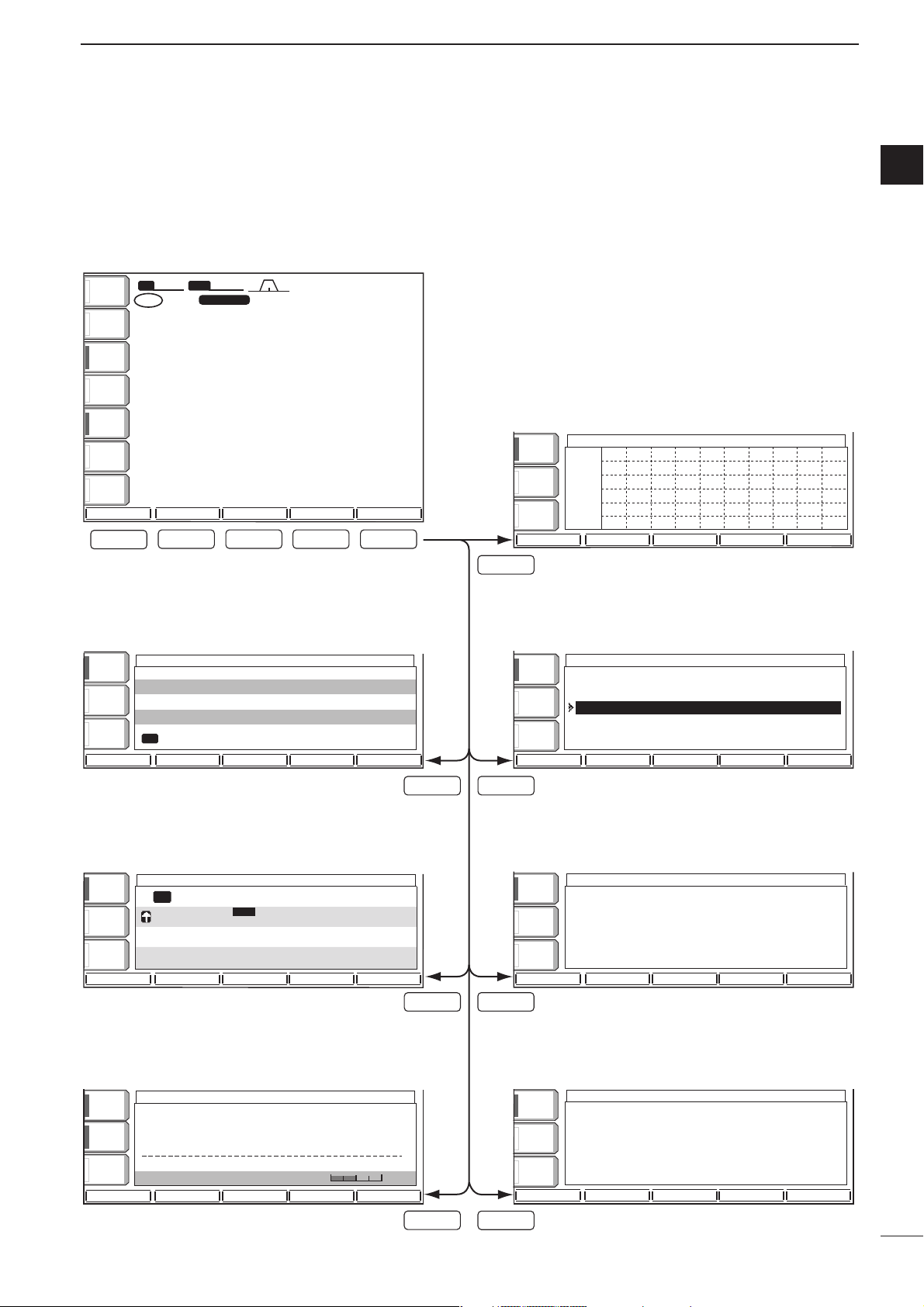
• Start up screen
• Voice recorder screen (p. 73)
• Memory keyer screen (CW mode: p. 40)
• Spectrum scope screen (p. 55)
• Memory channel screen (p. 78)
• Programmed scan screen (VFO mode: p. 84)
• RTTY decoder screen (RTTY mode: p. 46)
• Memory scan screen (Memory mode: p. 85)
F-1
F-1
F-4F-2
F-5
F-3
F-5
F-3
F-2 F-3 F-4 F-5
qw:pp
12:00
■ Screen menu arrangement
The following screens can be selected from the start
up screen. Choose the desired screen using the following chart.
Pushing [EXIT/SET] several times returns to the start
up screen. See p. 94 for set mode arrangement.
Page 16
11
1
PANEL DESCRIPTION
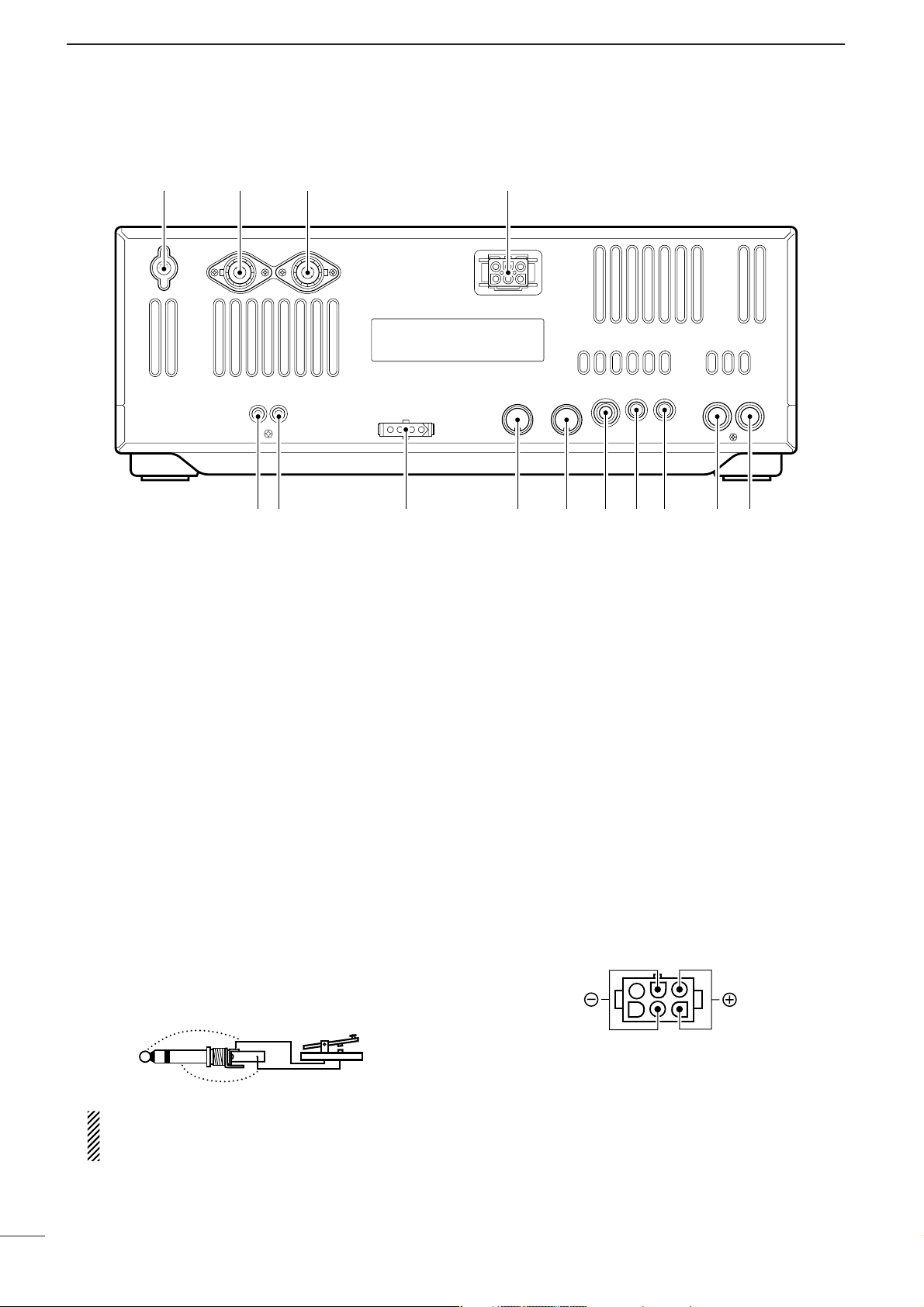
■ Rear panel
q TRANSVERTER JACK [XVERT] (p. 18)
External transverter input/output jack. Activated by
voltage applied to [ACC(2)] pin 6.
w RECEIVE ANTENNA CONNECTOR [RX ANT]
(p. 15)
Connects a 50 Ω general coverage antenna with an
RCA connector.
e TUNER CONTROL SOCKET [TUNER] (p. 15)
Accepts the control cable from an optional AH-4
HF/50 MHz AUTOMATIC ANTENNA TUNER or AH-3 HF
AUTOMATIC ANTENNA TUNER
.
r ACCESSORY SOCKET 1 [ACC(1)]
t ACCESSORY SOCKET 2 [ACC(2)]
Enable connection of external equipment such as a
linear amplifier, an automatic antenna selector/
tuner, TNC for data communications, etc.
• See p. 20 for socket information.
y STRAIGHT KEY JACK [KEY] (p. 14)
Accepts a straight key or external electronic keyer
with 1⁄4 inch standard plug.
•[ELEC-KEY] on the front panel can be used for a
straight key or external electronic keyer. Deactivate the
internal electronic keyer in keyer set mode. (p. 43)
If you use an external electronic keyer, make
sure the voltage retained by the keyer is less
than 0.4 V when the key is ON.
u CI-V REMOTE CONTROL JACK [REMOTE]
(p. 110)
➥ Connects a PC via the optional CT-17
CI-V LEVEL
CONVERTER
for external control of the transceiver
functions.
➥ Used for transceive operation with another Icom
CI-V transceiver or receiver.
i EXTERNAL SPEAKER JACK [EXT SP]
(pgs. 15, 116)
Accepts an 4–8 Ω speaker.
o ALC INPUT JACK [ALC] (p. 17)
Connects to the ALC output jack of a non-Icom linear amplifier.
!0 SEND CONTROL JACK [SEND] (p. 17)
Goes to ground while transmitting to control external equipment such as a linear amplifier.
• Max. control level: 16 V DC/0.5 A
!1 DC POWER SOCKET [DC 13.8V] (p. 16)
Accepts 13.8 V DC through the supplied DC power
cable (OPC-025D).
Rear panel view
!4 !3 !2
q w!0
ertyuio
!1
(+)
(_)
Page 17
12
1
PANEL DESCRIPTION
1
!2 ANTENNA CONNECTOR 1 [ANT1]
!3 ANTENNA CONNECTOR 2 [ANT2] (pgs. 13, 14)
Accept a 50 Ω antenna with a PL-259 connector.
When using an optional AH-4 HF/50 MHz AUTO-
MATIC ANTENNATUNER
or AH-3 HF AUTOMATIC AN-
TENNA TUNER
, connect it to the [ANT1] connector.
The internal antenna tuner activates for [ANT2] and
deactivates for [ANT1] when connecting the AH-4
or AH-3.
!4 GROUND TERMINAL [GND] (pgs. 13, 14)
Connect this terminal to a ground to prevent electrical shocks, TVI, BCI and other problems.
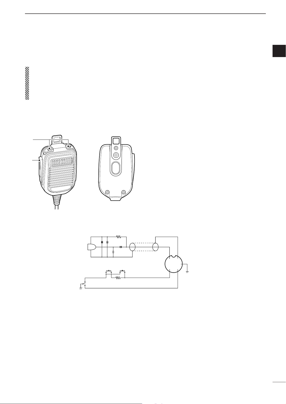
■ Microphone
(HM-36)
q UP/DOWN SWITCHES [UP]/[DN]
Change the selected readout frequency or memory
channel.
•Continuous pushing changes the frequency or memory
channel number continuously.
•While pushing [XFC], the transmit readout frequency
can be controlled while in spilt frequency operation.
•The [UP]/[DN] switch can simulate a key paddle. Preset
in the keyer set mode. (p. 43)
w PTT SWITCH
Push and hold to transmit; release to receive.
q
w
+
+
q
w
ert
y
u
i
4700p
4700p
10µ
0.33µ
MICROPHONE
MIC
ELEMENT
2k
470
DOWN UP
PTT
RECEIVE
TRANSMIT
MICROPHONE CABLE MICROPHONE PLUG
• HM-36 SCHEMATIC DIAGRAM
Page 18
2
INST ALLATION AND CONNECTIONS
■ Unpacking
After unpacking, immediately report any damage to the
delivering carrier or dealer. Keep the shipping cartons.
For a description and a diagram of accessory equipment included with the IC-756PROIII, see ‘Supplied
accessories’ on p. i of this manual.
■ Selecting a location
Select a location for the transceiver that allows adequate air circulation, free from extreme heat, cold, or
vibrations, and away from TV sets, TV antenna elements, radios and other electromagnetic sources.
The base of the transceiver has an adjustable stand
for desktop use. Set the stand to one of two angles depending on your operating conditions.
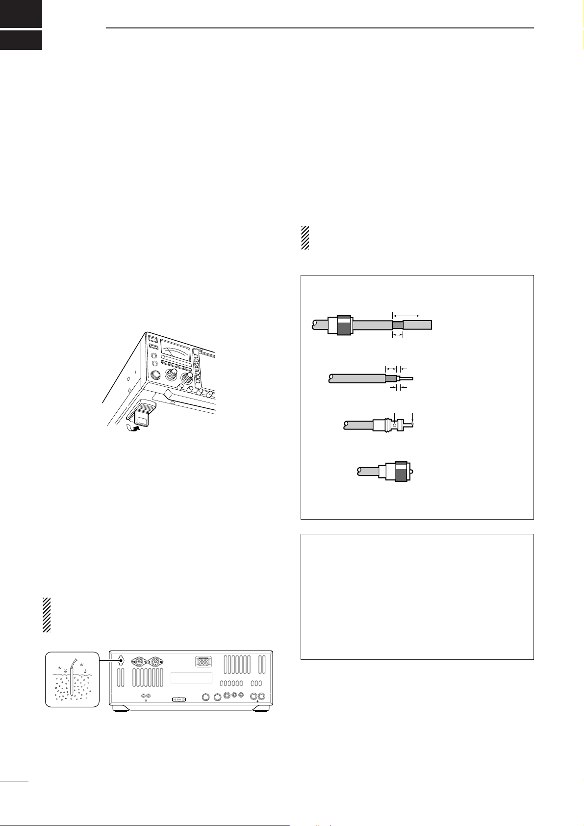
■ Grounding
To prevent electrical shock, television interference
(TVI), broadcast interference (BCI) and other problems, ground the transceiver through the GROUND
terminal on the rear panel.
For best results, connect a heavy gauge wire or strap
to a long earth-sunk copper rod. Make the distance between the [GND] terminal and ground as short as possible.
RWARNING: NEVERconnect the [GND]
terminal to a gas or electric pipe, since the connection could cause an explosion or electric shock.
■ Antenna connection
For radio communications, the antenna is of critical importance, along with output power and sensitivity. Select antenna(s), such as a well-matched 50 Ω antenna,
and feedline. 1.5:1 or better of Voltage Standing Wave
Ratio (VSWR) is recommended for your desired band.
Of course, the transmission line should be a coaxial
cable.
When using 1 antenna, use the [ANT1] connector.
CAUTION: Protect your transceiver from lightning
by using a lightning arrestor.
Antenna SWR
Each antenna is tuned for a specified frequency
range and SWR may be increased out-of-range.
When the SWR is higher than approx. 2.0:1, the
transceiver’s power drops to protect the final transistor. In this case, an antenna tuner is useful to match
the transceiver and antenna. Low SWR allows full
power for transmitting even when using the antenna
tuner. The IC-756PROIII has an SWR meter to monitor the antenna SWR continuously.
PL-259 CONNECTOR INSTALLATION EXAMPLE
30 mm ≈9⁄8 in 10 mm ≈3⁄8 in 1–2 mm ≈1⁄16 in
30 mm
10 mm (soft solder)
10 mm
1–2 mm
solder solder
Soft
solder
Coupling ring
Slide the coupling ring
down. Strip the cable
jacket and soft solder.
Slide the connector
body on and solder it.
Screw the coupling
ring onto the
connector body.
Strip the cable as
shown at left. Soft
solder the center conductor.
q
w
e
r
13
Page 19
2
14
INSTALLATION AND CONNECTIONS
2
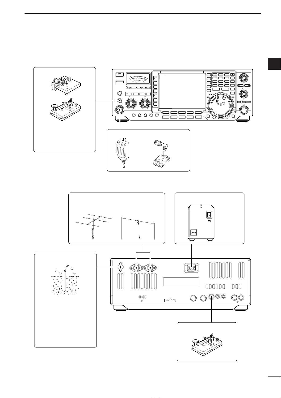
■ Required connections
•Front panel
•Rear panel
CW KEY
TIMER
POWER
TRANSMIT
PHONES
ELEC-KEY
MIC
HF/50MHz TRANSCEIVER
9
+20
5
+40
1
25 50
10
100
0
S
3
2
Po
1.5
1
20
10
SWR
0
COMP
dB
ALC
TUNER MONITOR NB NR
AF BAL NRRF/SQL
MIC GAIN RF POWER COMP KEY SPEEDBK-IN DELAY
1.8 3.5 7
1
2
REC/PLAY
CHANGE
M.SCOPE
SPLIT
DUAL
WATCH
VFO/
MEMO
MAIN/
SUB
RX
10 14 18
4
5
21 24 28
8
7
GENE
50
0
MP-W MP-R
F-INP
+60dB
F-1
F-2 F-3 F-4 F-5
SSB
CW/RTTY
AM/FM FILTER EXIT/SET
TWIN PBT
3
6
MW
9
PBT CLR
TS
LOCKTX
LOCK/SPEECH
CW PITCH
NOTCH
TX
RIT CLEAR
RIT/ TX
NOTCH
M-CL
ENT
XFC
A straight key can be used
when the internal electronic
keyer is turned OFF in keyer
set mode. (p. 43)
ANTENNA 1, 2 (p. 13)
[Example]: ANT1 for 1.8–18 MHz bands
GROUND (p. 13)
MICROPHONES (p. 116)
SM-20HM-36
DC POWER SUPPLY (p.16)
ANT2 for 21–50 MHz bands
PS-125
Use the heaviest gauge wire
or strap available and make
the connection as short as
possible.
Grounding prevents electrical
shocks, TVI and other
problems.
STRAIGHT KEY
Page 20
15
2
INSTALLATION AND CONNECTIONS
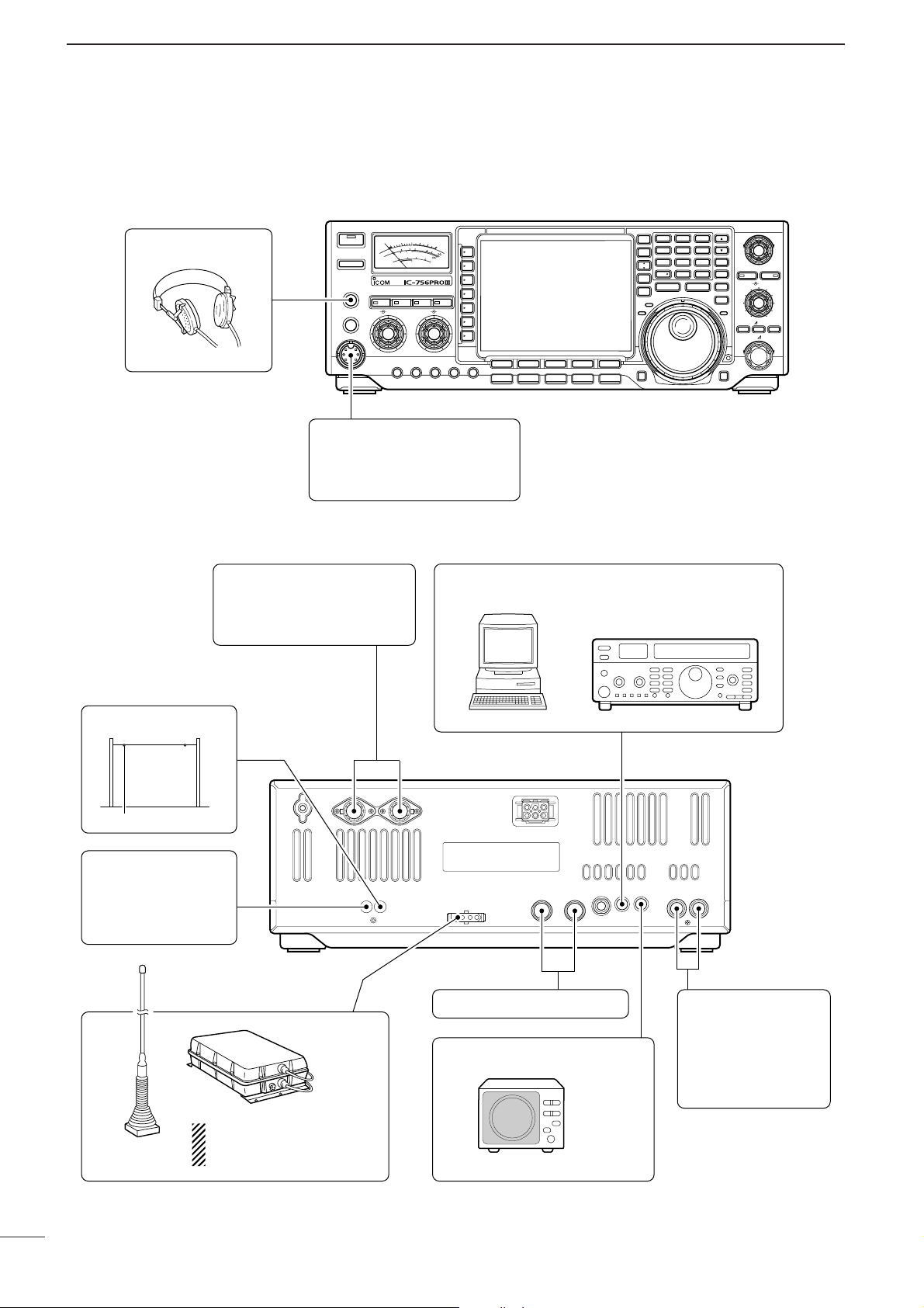
■ Advanced connections
•Front panel
•Rear panel
HEADPHONES
TIMER
HF/50MHz TRANSCEIVER
POWER
TRANSMIT
PHONES
ELEC-KEY
MIC
5
1
10
0
S
Po
1.5
1
SWR
0
COMP
ALC
TUNER MONITOR NB NR
AF BAL NRRF/SQL
MIC GAIN RF POWER COMP KEY SPEEDBK-IN DELAY
MIC
The AFSK modulation signal
can be input from [MIC]. (p. 19)
ANTENNA 1, 2 (pgs. 17, 18)
Connects a linear amplifier,
antenna selector, etc.
1.8 3.5 7
1
REC/PLAY
CHANGE
M.SCOPE
SPLIT
DUAL
WATCH
VFO/
MEMO
MAIN/
SUB
RX
10 14 18
4
21 24 28
7
GENE
50
MP-W MP-R
9
+20
+40
+60dB
25 50
100
3
2
20
10
dB
F-1
F-2 F-3 F-4 F-5
SSB
CW/RTTY
AM/FM FILTER EXIT/SET
[REMOTE] (p. 110)
Used for computer control and transceive operation.
TWIN PBT
3
2
6
5
MW
9
8
0
PBT CLR
M-CL
TS
XFC
LOCKTX
LOCK/SPEECH
NOTCH
TX
RIT CLEAR
RIT/ TX
NOTCH
CW PITCH
F-INP
ENT
RX ANTENNA
TRANSVERTER
(p. 18)
Connects a transverter
for V/UHF band use.
When using the AH-4/AH-3,
AH-2b
it must be connected to the
[ANT1] connector.
AH-4/AH-3
(p. 18)
ACC SOCKETS (pgs. 19, 20)
EXTERNAL SPEAKER (p. 116)
SP-23
[SEND], [ALC]
(p. 17)
Used for connecting a
non-Icom linear amplifier.
Page 21
16
2
INSTALLATION AND CONNECTIONS
2
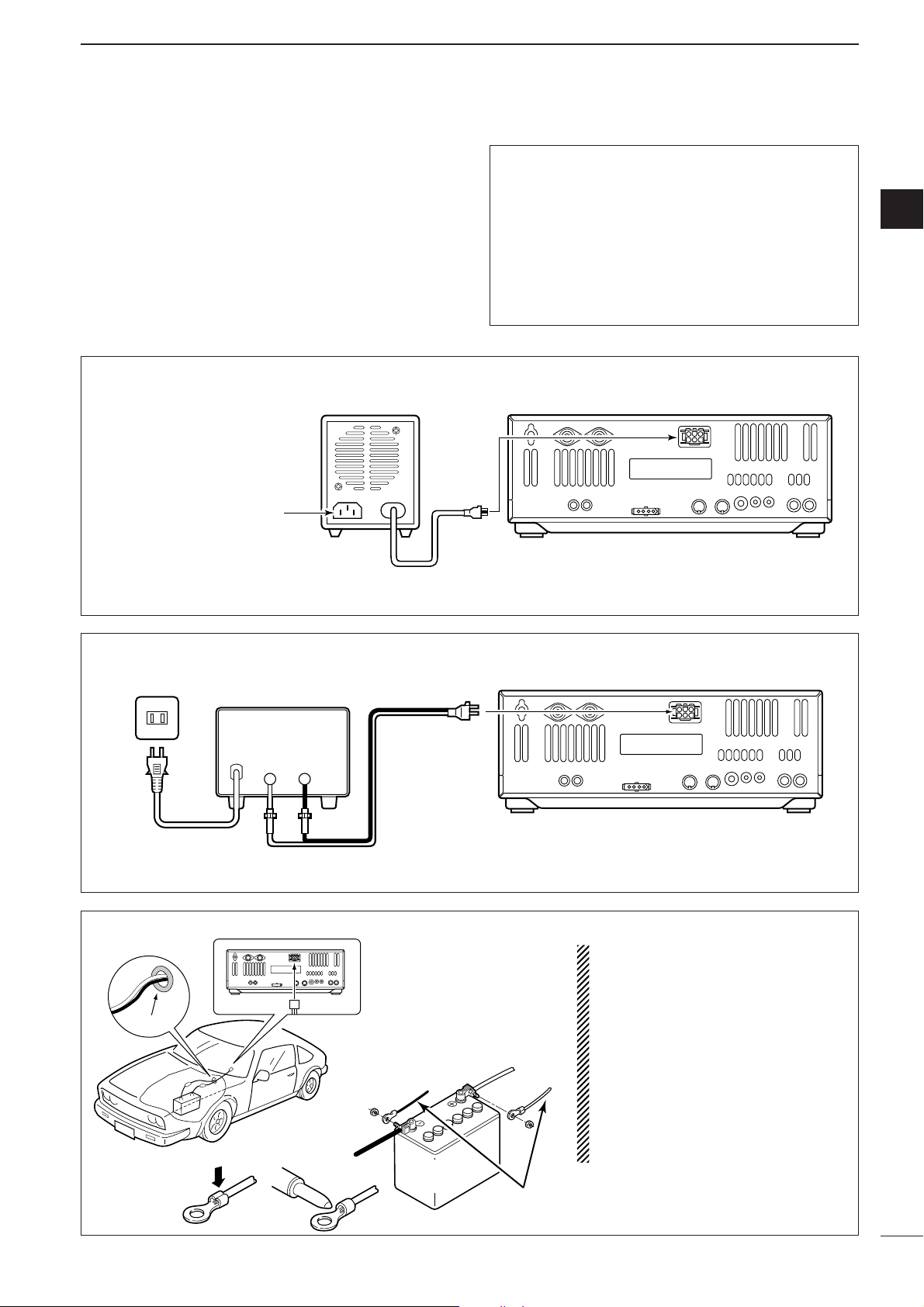
■ Power supply connections
Use the optional PS-125 DC power supply with a 25 A
capacity when operating the transceiver with AC
power. Refer to the diagrams below.
CAUTION: Before connecting the DC power
cable, check the following important items. Make
sure:
• The [POWER] switch is OFF.
•Output voltage of the power source is 12–15 V
when you use a non-Icom power supply.
• DC power cable polarity is correct.
Red : positive + terminal
Black : negative _ terminal
CONNECTING A DC POWER SUPPLY
to DC power
socket
A DC power supply
AC outlet
AC cable
30 A fuses
Supplied
DC power cable
13.8 V; at least 23 A
Black_Red
+
Transceiver
CONNECTING A VEHICLE BA TTER Y
12 V
battery
Supplied
DC power cable
+ red
_ black
Crimp
Solder
Grommet
NOTE: Use terminals for
the cable connections.
R WARNING NEVER connect to a battery without supplied
DC fuses, otherwise a fire hazard
may occur.
NEVER connect the transceiver
directly to a 24 V battery.
IMPORTANT! Detailed installation
notes for Icom mobile transceivers to
be fitted into vehicles are available.
Contact your Icom dealer or distributor.
CONNECTING PS-125 DC POWER SUPPLY
PS-125
Connect to an AC outlet
using the supplied AC cable.
DC power cable
DC power
socket
Transceiver
Page 22
17
2
INSTALLATION AND CONNECTIONS
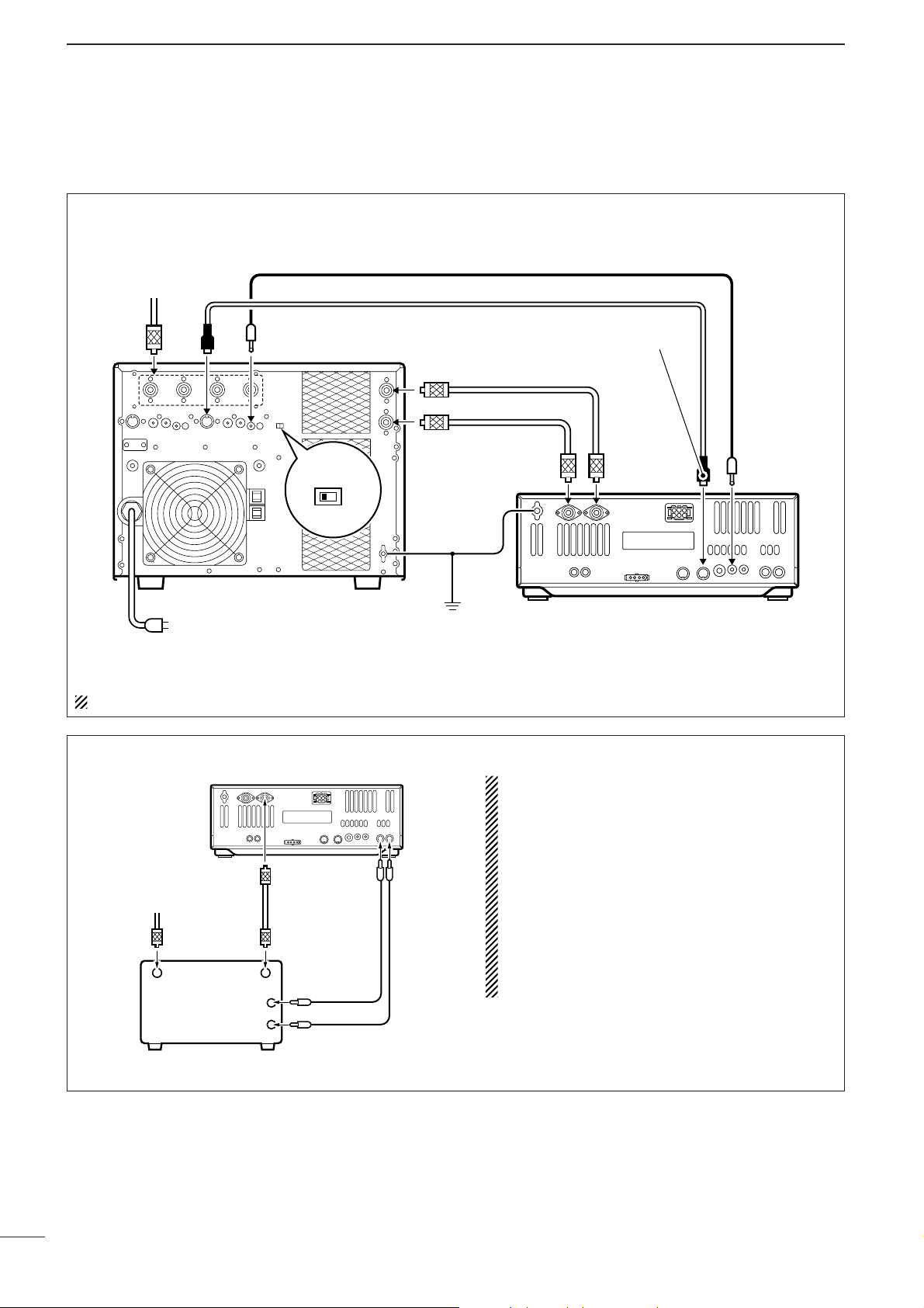
■ Linear amplifier connections
Use the [ANT1] connector when connecting a linear
amplifier.
CONNECTING THE IC-PW1/EURO
Turn OFF the transceiver’s antenna tuner while tuning the IC-PW1/EURO’s tuner.
CONNECTING A NON-ICOM LINEAR AMPLIFIER
R WARNING:
Set the transceiver output power and linear amplifier
ALC output level referring to the linear amplifier instruction manual.
The ALC input level must be in the range 0 V to –4 V,
and the transceiver does not accept positive voltage.
Non-matched ALC and RF power settings could cause
a fire or ruin the linear amplifier.
The specifications for the SEND relay are 16 V DC
0.5 A. If this level is exceeded, a large external relay
must be used.
Remote control cable (supplied with the IC-PW1/EURO)
ACC cable (supplied with the IC-PW1/EURO)
INPUT1
INPUT2
1&2
GND
ANT
To an
antenna
ACC-1
REMOTE
EXCITER
1
IC-PW1/EURO
AC outlet
(Non-European versions: 100–120/220–240 V
European version : 230 V)
Be sure to connect the cable
to the 7-pin ACC(2) jack.
Coaxial cable
(supplied with the IC-PW1/EURO)
Connect
Coaxial cable
(optional)
ANT2
GND
Ground
[INPUT2]
if necessary
ACC(2)
ANT1
Transceiver
REMOTE
To an
antenna
RF OUTPUT RF INPUT
Non-Icom linear amplifier
Transceiver
ANT1 ALC SEND
50 Ω coaxial
cable
ALC
SEND
Page 23
18
2
INSTALLATION AND CONNECTIONS
2
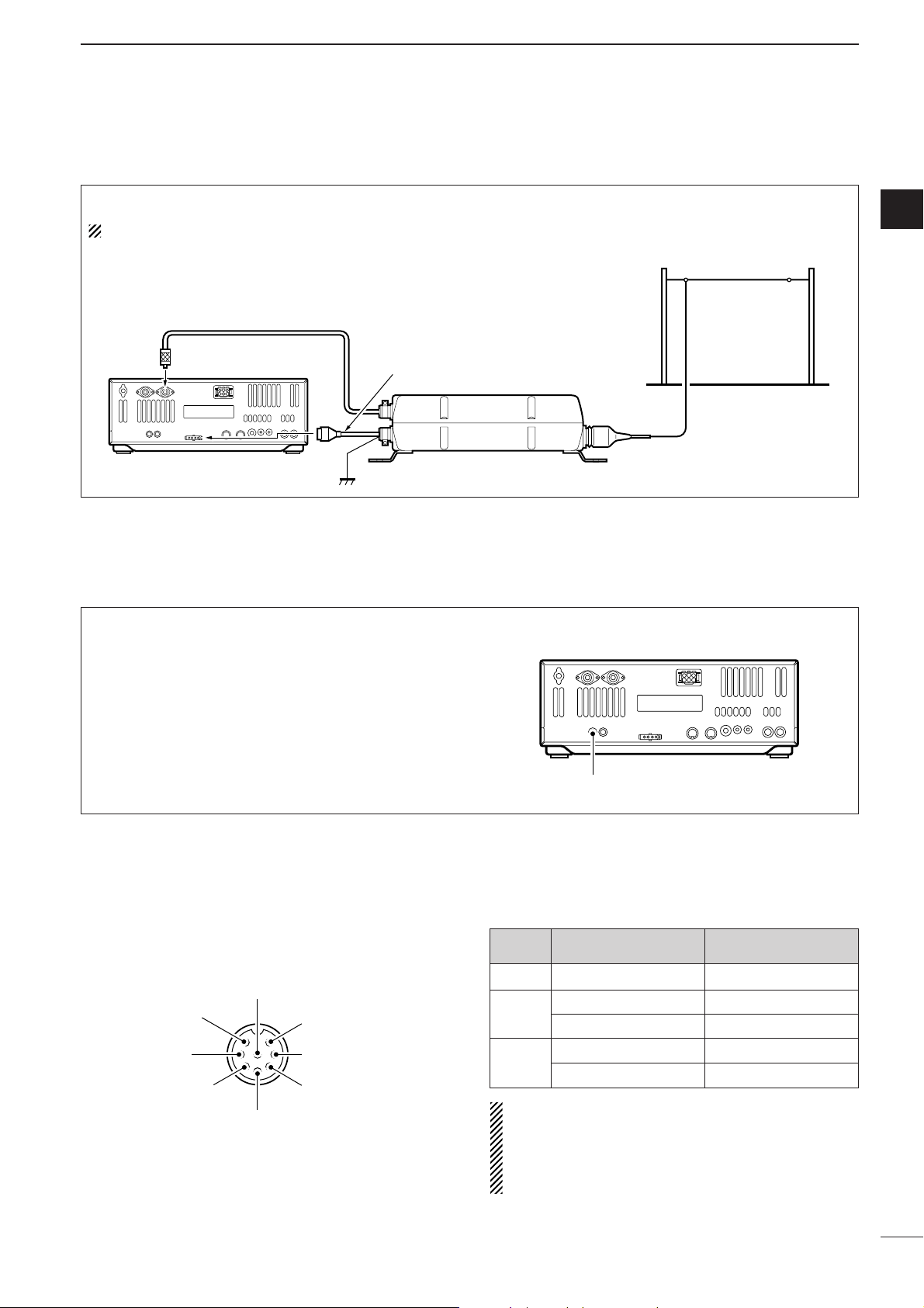
■ External antenna tuner connection
CONNECTING THE AH-4/AH-3
The AH-4 or AH-3 must be connected to [ANT1].
(Front panel view)
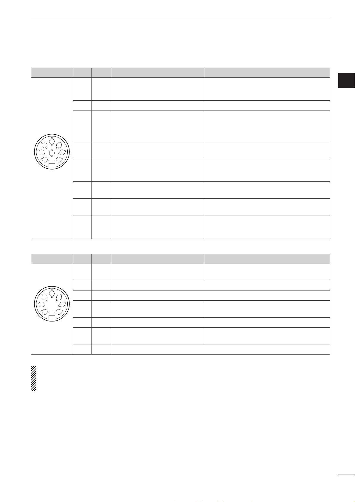
CAUTION: DO NOT short pin 2 to ground as this
can damage the internal 8 V regulator.
NOTE: DC voltage is applied to pin 1 for microphone operation. Take care when using a non-Icom
microphone.
[MIC]
FUNCTION DESCRIPTION
Pin No.
w +8 V DC output Max. 10 mA
e
Frequency up Ground
Frequency down Ground through 470 Ω
r
Squelch open “Low” level
Squelch closed “High” level
■ Microphone connector information
When 2 to 13.8 V is applied to pin 6 of [ACC(2)], the
[XVERT] jack is activated for transverter operation
and the antenna connectors do not receive or transmit any signals. (p. 20)
While receiving, the [XVERT] jack can be activated
as an input terminal from an external transverter.
While transmitting, the [XVERT] jack outputs signals
of the displayed frequency at –20 dBm (22 mV) as
signals for the external transverter.
Transverter jack
■ Transverter jack information
Coaxial cable (from the AH-4 or AH-3)
ANT1
Transceiver
Control cable
Ground
Long wire or optional AH-2b
AH-4 or AH-3
q Microphone input
w +8 V DC output
e Frequency up/down
i Main readout AF output
(varies with [AF]/[BAL])
u GND
(Microphone ground)
y GND (PTT ground)
t PTT
r Main readout squelch switch
Page 24
19
2
INSTALLATION AND CONNECTIONS
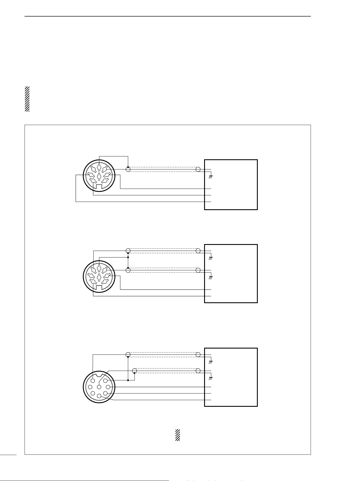
AF input
Ground (GND)
PTT
SQUELCH input*
RTTY keying
* Connect the SQUELCH line when required.
Terminal unit (TU) or
Terminal Node Controller (TNC)
[ACC(1)] socket
(Rear panel view)
1
2
3
4
5
6
7
8
AFSK output
AF input
Ground (GND)
Ground (GND)
PTT
SQUELCH input*
* Connect the SQUELCH line when required.
Terminal Node Controller (TNC)
or Scan converter
[ACC(1)] socket
(Rear panel view)
1
2
3
4
5
6
7
8
AF input
Ground (GND)
AFSK output
PTT
SQUELCH input*
* Connect the SQUELCH line when required.
Terminal Node Controller (TNC)
or Scan converter
[MIC] connector
(Front panel view)
1
2
345
678
■ FSK and AFSK (SSTV) connections
To connect a terminal unit, TNC or scan converter,
refer to the diagram below.
For RTTY operation:
Narrow filter settings may not pass RTTY signals.
Be sure to select the appropriate IF filter settings
corresponding to the signal width. (p. 61)
FSK (RTTY) connection
Use RTTY mode for
operation
AFSK and SSTV connections
Use SSB or FM mode
for operation
AFSK and SSTV connections via microphone connector
Use SSB or FM mode
for operation
When connected to the [MIC] connector, [MIC
GAIN] and [AF] control adjustment is required.
Page 25
20
2
INSTALLATION AND CONNECTIONS
■ Accessory connector information
If the CW side tone level limit or beep level limit is in
use, the CW side tone or beep tone decreases from
the fixed level when the [AF] control is rotated
above a specified level, respectively. (p. 96)
ACC (1)
PIN No.
NAME DESCRIPTION SPECIFICATIONS
1
2
3
4
5
6
7
8
“High” level : More than 2.4 V
1RTTY Controls RTTY keying “Low” level : Less than 0.6 V
Output current : Less than 2 mA
2 GND Connects to ground. Connected in parallel with ACC(2) pin 2.
Input/output pin.
Ground level : –0.5 V to 0.8 V
3 SEND Goes to ground when transmitting.
Output current : Less than 20 mA
When grounded, transmits.
Input current (Tx) : Less than 200 mA
Connected in parallel with ACC(2) pin 3.
4 MOD
Modulator input. Input impedance : 10 kΩ
Connects to a modulator. Input level : Approx. 100 mV rms
AF detector output.
Output impedance : 4.7 kΩ
5AFFixed, regardless of [AF] position
Output level : 100–300 mV rms
in default settings. (see notes below)
6 SQLS
Squelch output. SQL open : Less than 0.3 V/5 mA
Goes to ground when squelch opens.
SQL closed : More than 6.0 V/100 µA
7 13.8 V 13.8 V output when power is ON.
Output current : Max. 1 A
Connected in parallel with ACC(2) pin 7.
Control voltage : –4 V to 0 V
8 ALC ALC voltage input. Input impedance : More than 10 kΩ
Connected in parallel with ACC(2) pin 5.
ACC (2)
PIN No.
NAME DESCRIPTION SPECIFICATIONS
1
2
3
4
5
6
7
18VRegulated 8 V output.
Output voltage : 8 V ±0.3 V
Output current : Less than 10 mA
2 GND Same as ACC(1) pin 2.
3 SEND Same as ACC(1) pin 3.
4 BAND
Band voltage output.
Output voltage : 0 to 8.0 V
(Varies with amateur band)
5 ALC Same as ACC (1) pin 8.
6TRV
Activates [XVERT] input/output Input impedance : More than 10 kΩ
when “HIGH” voltage is applied. Input voltage : 2 to 13.8 V
7
13.8 V
Same as ACC(1) pin 7.
Rear panel view
Rear panel view
2
Page 26
Before first applying power, make sure all connections
required for your system are complete by referring to
Section 2. Then, reset the transceiver using the following procedure.
Resetting CLEARS all programmed contents in
memory channels and returns programmed values
in set mode to default values.
q Make sure the transceiver power is OFF.
w While pushing [M-CL] and [(F-INP)ENT], push
[POWER] to turn power ON.
• The internal CPU is reset.
•A/D convertor calibration of the DSP unit starts and it
takes 10 sec.
•The transceiver displays its initial VFO frequencies when
resetting is complete.
e Correct the set mode settings after resetting, if de-
sired.
■ Initial settings
After resetting the transceiver, set controls and
switches as shown in the figure below.
Under cooler temperatures, the LCD may appear
dark and unstable after turning power ON. This is
normal and does not indicate any equipment malfunction.
CW : Max. clockwise
CCW : Max. counterclockwise
■ When first applying power (CPU resetting)
Turn power ON, then check the display. If any of the
following indicators appear, turn them OFF as follows:
• Quick tuning step indicator “▼”: Push [TS].
•1 Hz frequency readout : Push [TS] for 2 sec.
(while quick tuning
step is OFF)
• RIT indicator “ ” : Push [RIT].
• ∂TX indicator “ ” : Push [∂∂TX].
• Split indicator “ ” : Push [SPLIT].
• Dualwatch indicator “ ” : Push
[DUALWATCH].
•
Twin peak filter indicator “ ”
: Push [RTTY FIL].
• Auto notch indicator “ ” : Push [NOTCH].
• Manual notch indicator “ ” : Push [NOTCH].
TPF
DUAL-W
SPLIT
TX
RIT
3
21
BASIC OPERATION
[POWER] [F-INP] [M-CL]
[ANT]: 1
[METER]: Po
[POWER]: OFF
[TUNER], [MONITOR],
[NB], [NR]: OFF
[AF]: Max. CCW
[RF/SQL]: 12 o’clock
[MIC GAIN]: 10–12 o’clock
[RF POWER]: Max. CW
[BAL]: Center [AGC]: MID*
[COMP]*
[1/4],*
2
: OFF WIDE;
2
[TONE]*2: OFF
[P.AMP]: 1
[ATT]: OFF
2
[VOX],*
[RTTY FIL]*2: OFF
[BK-IN],*
[PBT CLR]: OFF
1
2
[LOCK]: OFF
*1 FAST in FM mode.
2
*
Appears in some modes.
[NOTCH]: OFF
RIT
∂TX
SPLIT
DUAL-W
AN
TPF
MN
Page 27
22
3
BASIC OPERATION
3
■ VFO description
VFO is an abbreviation of Variable Frequency Oscillator, and traditionally refers to an oscillator.
The transceiver’s VFO is somewhat different. The VFO
of the IC-756PROIII acts like a computer’s window and
can show one frequency and one operating mode.
You can call up a desired frequency to the VFO with
the keypad, memo pad-read switch (see p. 82) or the
memory transfer function (see p. 80). You can also
change the frequency with the tuning dial and select
the operating mode with the mode switches.
During dualwatch or split frequency operation, the sub
VFO is functional (non-outline, non-spotted, larger frequency characters). While pushing [XFC] during split
frequency operation, you can change the transmit
readout frequency with the keypad, memo pad-read
switch or the memory transfer function.
METER
Po
ANT
1
BWBW
2.4k2.4k
SFTSFT
0
VFOVFO
FIL2FIL2
USBUSB
TXTX
1
CWCW
qr.qpp.pp
21.076.5021.076.50
qw:pp
12:0012:00
Select
TUNING DIAL
MEMORY
CHANNEL
MODE
SWITCHES
MEMO PAD
KEYPAD
(BAND KEY)
Transfer
Transfer
Transfer
Change
21.295 MHz
28.025 MHz
7.001 MHz
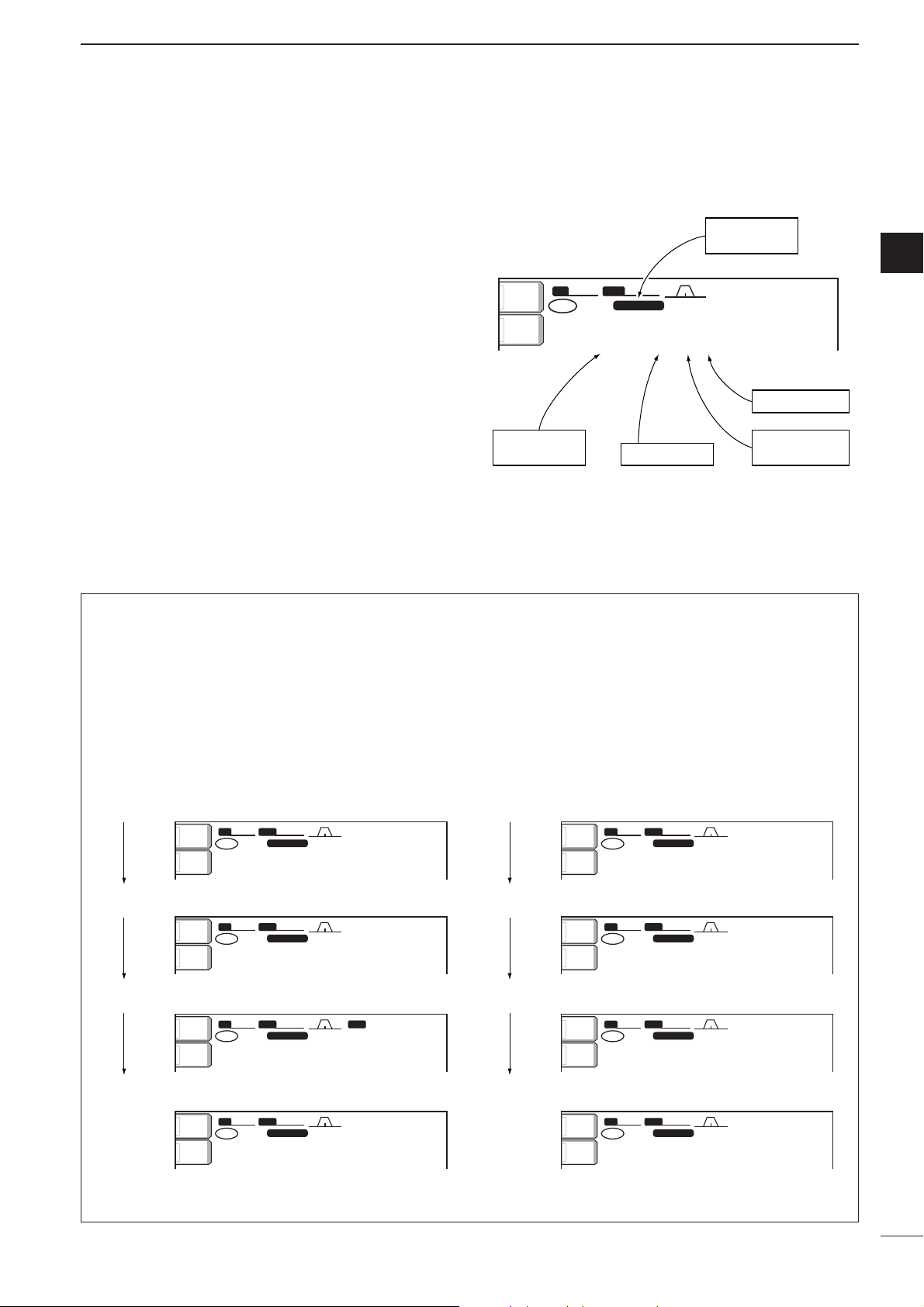
•Differences between VFO mode and memory mode
VFO MODE
VFO shows a frequency and operating mode. If the
frequency or operating mode is changed, the VFO
automatically memorizes the new frequency or new
operating mode.
When a VFO is selected from another band or memory mode, the frequency and operating mode last
used for that VFO appear.
[EXAMPLE]
MEMORY MODE (pgs. 77–81)
Each memory channel shows a frequency and operating mode like a VFO. Even if the frequency or mode
is changed, the memory channel does not memorize
the new frequency or operating mode.
When the memory channel is selected from another
memory channel or VFO mode, the memorized frequency and operating mode appear.
[EXAMPLE]
METERMETER
PoPo
ANTANT
1
METERMETER
PoPo
ANTANT
1
METERMETER
PoPo
ANTANT
1
METERMETER
PoPo
ANTANT
1
BWBW
2.4k2.4k
SFTSFT
0
VFOVFO
FIL2FIL2
USBUSB
TXTX
1
CWCW
qr.qwe.pp
21.076.5021.076.50
BWBW
500 500
SFTSFT
0
BPFBPF
1
FIL2FIL2
CWCW
TXTX
VFOVFO
USBUSB
wq.puy.tp
14.123.0014.123.00
BWBW
2.4k2.4k
SFTSFT
0
VFOVFO
FIL2FIL2
USBUSB
TXTX
1
CWCW
qr.qwe.pp
21.076.5021.076.50
BWBW
2.4k2.4k
SFTSFT
0
VFOVFO
FIL2FIL2
USBUSB
TXTX
1
CWCW
qr.qpp.pp
21.076.5021.076.50
BWBW
2.4k2.4k
SFTSFT
0
FIL2FIL2
USBUSB
TXTX
VFOVFO
USBUSB
qr.qpp.pp
14.100.0014.100.00
BWBW
2.4k2.4k
SFTSFT
0
FIL2FIL2
USBUSB
TXTX
VFOVFO
USBUSB
wq.wrt.pp
14.100.0014.100.00
BWBW
2.4k2.4k
SFTSFT
0
FIL2FIL2
USBUSB
TXTX
VFOVFO
USBUSB
qr.qwe.pp
14.100.0014.100.00
BWBW
2.4k2.4k
SFTSFT
0
1
FIL2FIL2
USBUSB
TXTX
VFOVFO
USBUSB
qr.qpp.pp
14.100.0014.100.00
1
1212
1
METERMETER
PoPo
ANTANT
1
METERMETER
PoPo
ANTANT
1
METERMETER
PoPo
ANTANT
1
METERMETER
PoPo
ANTANT
1
qw:pp
12:0012:00
qw:pp
12:0012:00
qw:pp
12:0012:00
qw:pp
12:0012:00
qw:pp
12:0012:00
qw:pp
12:0012:00
qw:pp
12:0012:00
qw:pp
12:0012:00
VFO is selected.
The frequency is changed.
Memory mode is selected.
VFO is selected again.
Memory channel 1 is selected.
The frequency is changed.
Another memory channel is selected.
Memory channel 1 is selected again.
Changed frequency (14.123 MHz) appears.
Changed frequency (14.123 MHz) does not appear and
memorized frequency (14.100 MHz) appears instead.
Page 28
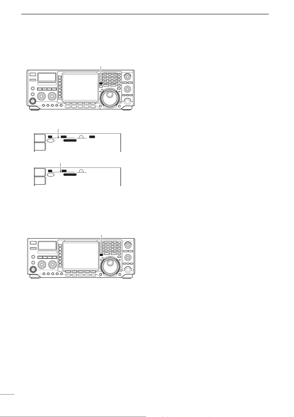
23
3
BASIC OPERATION
➥ Push [VFO/MEMO] to switch between VFO and
memory modes.
•“VFO” appears when VFO mode, or the selected memory channel number appears when memory mode is
selected beside the frequency readout.
•Pushing [VFO/MEMO] for 1 sec. transfers the contents
of the selected memory channel to VFO mode. (p. 80)
SFTSFT
0
FIL2FIL2
CWCW
TXTX
USBUSB
qr.qot.pp
14.100.0014.100.00
BPFBPF
1
VFOVFO
BWBW
500 500
SFTSFT
0
FIL2FIL2
USBUSB
TXTX
CWCW
qr.qpp.pp
14.195.0014.195.00
VFOVFO
1
BWBW
2.4k2.4k
ANTANT
1
METERMETER
PoPo
ANTANT
1
METERMETER
PoPo
qw:pp
12:00
qw:pp
12:00
“VFO” indicator
Memory channel number
[VFO/MEMO]
■ Selecting VFO/memory mode
➥ Push [MAIN/SUB] to select access to the main or
sub readout.
•The sub readout frequency is displayed in outline or
mesh font. The sub readout functions only during split
oeration or dualwatch.
[MAIN/SUB]
■ Main/Sub band selection
Page 29
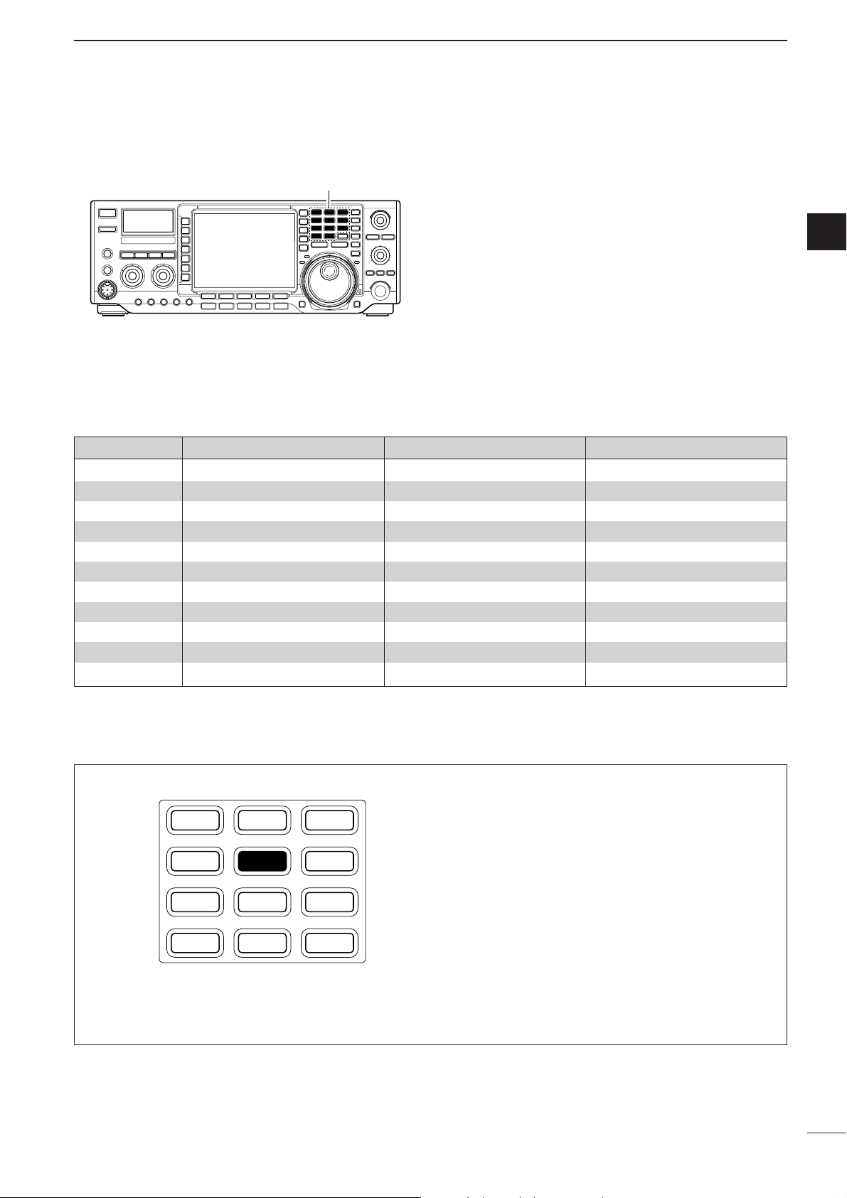
24
3
BASIC OPERATION
3
The triple band stacking register provides 3 memories
in one band. 3 sets of a frequency and operating mode
on each band are automatically stored when used.
If a band key is pushed once, the frequency and operating mode last used are called up. When the key is
pushed again, another stored frequency and operating
mode are called up.
This function is convenient when you operate 3 operating modes on one band. For example, one register
is used for a CW frequency, another for an SSB frequency and the other one for an RTTY frequency.
See the table below for a list of the band available and
the default settings for each band.
Band keys
■ Selecting an operating band
BAND REGISTER 1 REGISTER 2 REGISTER 3
1.8 MHz 1.900000 MHz CW 1.910000 MHz CW 1.915000 MHz CW
3.5 MHz 3.550000 MHz LSB 3.560000 MHz LSB 3.580000 MHz LSB
7 MHz 7.050000 MHz LSB 7.060000 MHz LSB 7.020000 MHz CW
10 MHz 10.120000 MHz CW 10.130000 MHz CW 10.140000 MHz CW
14 MHz 14.100000 MHz USB 14.200000 MHz USB 14.050000 MHz CW
18 MHz 18.100000 MHz USB 18.130000 MHz USB 18.150000 MHz USB
21 MHz 21.200000 MHz USB 21.300000 MHz USB 21.050000 MHz CW
24 MHz 24.950000 MHz USB 24.980000 MHz USB 24.900000 MHz CW
28 MHz 28.500000 MHz USB 29.500000 MHz USB 28.100000 MHz CW
50 MHz 50.100000 MHz USB 50.200000 MHz USB 51.000000 MHz FM
General 15.000000 MHz USB 15.100000 MHz USB 15.200000 MHz USB
q Push [(14)5], then select a frequency and an op-
erating mode.
•Frequency and operating mode are memorized in the
first band stacking register.
w Push [(14)5] again, then select another frequency
and operating mode.
•This frequency and operating mode are memorized in
the second band stacking register.
e Push [(14)5] again, then select another frequency
and operating mode.
•This frequency and operating mode are memorized in
the third band stacking register.
•When a fourth frequency and operating mode are selected on a band, the first register set in step q, is over
written.
[Example]: 14 MHz band
1.8 3.5 7
10 14 18
21 24 28
GENE
•
50
123
4 5 6
789
0
F-INP
ENT
DD
Using the band stacking registers
Page 30
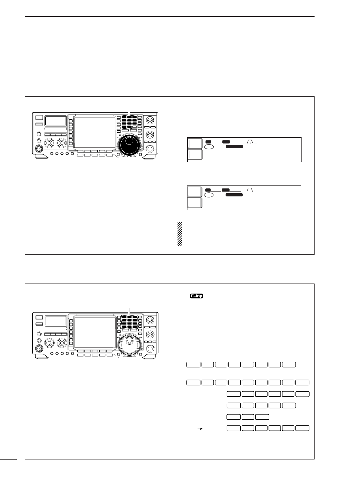
25
3
BASIC OPERATION
The transceiver has several tuning methods for convenient frequency tuning.
■ Frequency setting
DD
Direct frequency entry with the keypad
DD
Tuning with the tuning dial
q Push the desired band key on the keypad 1–3
times.
•3 different frequencies can be selected on each band
with the band key. (See previous page “Using the band
stacking register.”)
w Rotate the tuning dial to set the desired frequency.
If the dial lock function is activated, the lock indicator lights, and the tuning dial does not function. In
this case, push [LOCK/SPEECH] to deactivate the
lock function. (p. 65)
BW
2.4k
SFT
VFO
FIL2
USB
TX
CW
21.076.50
12:00
BW
2.4k
SFT
VFO
FIL2
USB
TX
CW
21.076.50
12:00
The transceiver has a keypad for direct frequency
entry as described right.
q Push [(F-INP)ENT].
•“ ” appears.
w Input the desired frequency.
•Push [(GENE)•] to input “ • (decimal point)” between
the MHz units and kHz units.
e Push [(F-INP)ENT] to set the input frequency.
•To cancel the input, push [MAIN/SUB] instead of
[(F-INP)ENT].
[EXAMPLES]
Band keys
Tuning dial
ANT
1
METER
Po
2.4k
BW
VFO
TX
wq.wpp.pp
1
SFT
0
USB
21.076.50
FIL2
CW
qw:pp
12:00
ANT
1
METER
Po
2.4k
BW
VFO
TX
wq.wot.pp
1
SFT
0
USB
21.076.50
FIL2
CW
qw:pp
12:00
Keypad
14.025 MHz
F-INP
1 04 2• 5
ENT
18.0725 MHz
F-INP
ENT
1
706 kHz
5.100 MHz
7.000 MHz
21.280 21.245
F-INP
F-INP
F-INP
F-INP
F-INP
F-INP
08 7• 2 5
F-INP
7
7 0• 6
2 4• 5
ENT
ENT
ENT
ENT
• 15
ENT
F-INP
F-INP
ENT
F-INP
F-INP
ENT
F-INP
ENT
ENT
ENT
Page 31

26
3
BASIC OPERATION
3
DD
Quick tuning step
The operating frequency can be changed in kHz
steps (0.1, 1, 5, 9, 10, 12.5, 20 or 25 kHz selectable)
for quick tuning.
q Push [TS] momentarily to turn the quick tuning
function ON.
•“Z” appears when the quick tuning function ON.
w Rotate the tuning dial to change the frequency in
programmed kHz steps.
e Push [TS] again to turn the quick tuning function
OFF.
•“Z” disappears.
r Rotate the tuning dial for normal tuning, if desired.
BWBW
2.4k2.4k
SFTSFT
0
FIL2FIL2
TXTX
CWCW
qr.qpp.pp
21.076.5021.076.50
VFOVFO
USBUSB
1
METER
Po
ANT
1
qw:pp
12:0012:00
Quick tuning indicator
[TS]
Tuning dial
DD
Selecting “kHz” step
q Push [TS] momentarily to turn the quick tuning
step ON.
•“Z” appears when the quick tuning function ON.
w Push [TS] for 1 sec. to enter the tuning step set-
ting display.
• Selected tuning steps for all modes appear.
e Select the desired operating mode.
r Rotate the tuning dial to select the desired tuning
step from 0.1, 1, 5, 9, 10, 12.5, 20 or 25 kHz.
•Push [(F-3)DEF] for 1 sec. to return to the default set-
ting, if desired.
t Repeat steps e and r to select quick tuning
steps for other modes, if desired.
y Push [EXIT/SET] to exit the setting display.
DEFDEF
TSTS
FMFMAMAM
1010
(kHz)(kHz)
1111
SSBSSB CWCW RTTYRTTY
VOXVOX
OFFOFF
COMPCOMP
OFFOFF
WIDEWIDE
AGCAGC
MIDMID
[TS]
Tuning dial
Mode selection
Page 32

27
3
BASIC OPERATION
DD
Selecting 1 Hz step
The minimum tuning step of 1 Hz can be used for fine
tuning.
q Push [TS] to turn OFF the quick tuning step.
•“▼” does not appear.
w Push [TS] for 1 sec. to turn the 1 Hz tuning step
ON and OFF.
•RIT and/or ∂TX also functions in 1 Hz tuning step when
used.
SCOPESCOPE
VOICEVOICE
MEMORYMEMORY
SCANSCAN
BWBW
2.4k2.4k
SFTSFT
0
FIL2FIL2
USBUSB
1
TXTX
VFOVFO
1
USBUSB
USBUSB
USBUSB
FIL2FIL2
qr.qot.ppp
qr.wpt.ppp
14.100.0014.100.00
14.100.0014.100.00
VFOVFO
ATTATT
0FF0FF
METERMETER
PoPo
P.AMPP.AMP
1
VOXVOX
OFFOFF
COMPCOMP
OFFOFF
WIDEWIDE
AGCAGC
MIDMID
ANTANT
1
qw:pp
12:0012:00
1 Hz step indicator
[TS]
Tuning dial
DD
1
⁄
4 tuning function (SSB data/CW/RTTY only)
While operating in SSB data/CW/RTTY, the 1⁄4 tuning
function is available for critical tuning. Dial rotation is
reduced to 1⁄4 of normal when the 1⁄4 function is in
use.
➥ Push [1/4] to toggle the
1
⁄
4 function ON and OFF.
1/4
OFF
1/4
ON
1
⁄4 tuning function OFF
1
⁄4 tuning function ON
[1/4]
Page 33

28
3
BASIC OPERATION
3
DD
Auto tuning step function
When rotating the tuning dial rapidly, the tuning speed
accelerated automatically as selected.
q Push [EXIT/SET] several times to close a multi-
function screen, if necessary.
w Push [EXIT/SET] for 1 sec. to select the set mode
menu screen.
e Push [(F-5)OTHERS] to enter miscellaneous (oth-
ers) set mode.
r Push [(F-1)YY] or [(F-2)ZZ] to select “MAIN DIAL
Auto TS.”
t Rotate the tuning dial to select the desired condi-
tion from high, low and OFF.
•High: Approx. 5 times faster
•Low: Approx. twise faster
•OFF: Auto tuning step is turned OFF
y Push [EXIT/SET] to exit the set mode.
OTHERS OTHERS
SETSET
é
è
DEFDEF
WIDEWIDE
BK-INBK-IN
OFFOFF
1/41/4
OFFOFF
AGCAGC
MIDMID
MemopadNumbers OFF
MAIN DIAL Auto TS HIGH
MIC UP/Down Speed HIGH
Quick RIT/∂TX Clear OFF
SSB/CW Synchronous Tuning OFF
CW Normal Side LSB
External Keypad Auto
Tuning dial
[(F-2)Z] [(F-5)OTHERS]
[(F-1)Y] [EXIT/SET]
DD
Band edge warning beep
When selecting a frequency, that lies outside of a
band’s specified frequency range, a warning beep
sounds.
This function can be turned OFF in set mode, if desired.
q Push [EXIT/SET] several times to close a multi-
function screen, if necessary.
w Push [EXIT/SET] for 1 sec. to select the set mode
menu screen.
e Push [(F-5)OTHERS] to enter miscellaneous (oth-
ers) set mode.
r Push [(F-1)YY] or [(F-2)ZZ] to select “Beep (Band
Edge).”
t Rotate the tuning dial to turn the band edge warn-
ing beep ON and OFF.
y Push [EXIT/SET] to exit the set mode.
OTHERS OTHERS
SETSET
é
è
DEFDEF
WIDEWIDE
BK-INBK-IN
OFFOFF
1/41/4
OFFOFF
AGCAGC
MIDMID
Beep(Confirmation) ON
Beep(Band Edge) ON
RF/SQL Control RF+SQL
Quick Dualwatch ON
Quick SPLIT ON
FM SPLIT Offset(HF) -0.100MHz
FM SPLIT Offset(50M) -0.100MHz
Tuning dial
[(F-2)Z] [(F-5)OTHERS]
[(F-1)Y] [EXIT/SET]
Page 34

29
3
BASIC OPERATION
■ Operating mode selection
SSB (LSB/USB), SSB data (LSB-D/USB-D), CW, CW
reverse (CW-R), RTTY, RTTY reverse (RTTY-R), AM,
AM data (AM-D), FM and FM data (FM-D) are available in the IC-756PROIII. Select the desired operation
mode as follows.
To select a mode of operation, push the desired mode
switch momentarily. Push the switch again to toggle
between USB and LSB, CW/CW-R and RTTY/RTTYR, AM and FM, if necessary. Push the switch for 1 sec.
to toggle between CW and CW-R, RTTY and RTTY-R,
or to select data mode, if necessary.
See the diagram below left for the order of selection.
Microphone signals are muted when data mode is
selected.
•Selecting SSB mode
➥ Push [SSB] to select USB or LSB.
•USB is selected first when above 10 MHz; or LSB is selected first when below 10 MHz operation.
•After USB or LSB is selected, push [SSB] to toggle be-
tween USB and LSB.
•After USB or LSB is selected, push [SSB] for 1 sec. to
select USB-D or LSB-D mode, respectively.
•Selecting CW/RTTY mode
➥ Push [CW/RTTY] to select CW or RTTY.
•After CW or RTTY is selected, push [CW/RTTY] to toggle between CW and RTTY.
•After CW or RTTY is selected, push [CW/RTTY] for
1 sec. to toggle between CW and CW reverse, or, RTTY
and RTTY reverse mode, respectively.
•Selecting AM/FM mode
➥ Push [AM/FM] to select AM or FM.
•After AM or FM is selected, push [AM/FM] to toggle be-
tween AM and FM.
•After AM or FM is selected, push [AM/FM] for 1 sec. to
select AM-D or FM-D mode, respectively.
Mode selection
SSB
CW/RTTY
AM/FM
USB-D USB
CW-R CW
AM-D AM
Push mode switch
for 1 sec.
Push mode switch
momentarily.
LSB LSB-D
RTTY RTTY-R
FM FM-D
■ Volume setting
➥ Rotate [AF] control clockwise to increase; counter-
clockwise to decrease the audio output level.
• Set a suitable audio level.
Audio output
increases
Audio output
decreases
[AF]
Page 35

30
3
BASIC OPERATION
3
■ Squelch and receive (RF) sensitivity
Adjusts the RF gain and squelch threshold level. The
squelch removes noise output from the speaker
(closed position) when no signal is received.
•The squelch is particularly effective for FM. It is also available for other modes.
•12 to 1 o’clock position is recommended for any setting of
the [RF/SQL] control.
•The control can be set as ‘Auto’ (RF gain control in SSB,
CW and RTTY; squelch control in AM and FM) or squelch
control (RF gain is fixed at maximum) in set mode as follows. (p. 99)
Adjusting RF gain (Receive sensitivity)
Normally, [RF/SQL] is set to the 11 o’clock position.
Rotate [RF/SQL] to the 11 o’clock position for maximum sensitivity.
•Rotating counterclockwise from the maximum position reduces sensitivity.
• The S-meter indicates receive sensitivity.
Adjusting squelch (Removing non-signal noise)
Rotate [RF/SQL] clockwise when receiving no signal,
until the noise just disappears.
• [RX] indicator light goes out.
•Rotating [RF/SQL] past the threshold point invokes the S-
meter squelch— this allows you to set a minimum signal
level needed to open the squelch.
•When setting as RF gain/squelch control
•When functioning as RF gain control
(Squelch is fixed open; SSB, CW, RTTY only)
•When functioning as squelch control
(RF gain is fixed at maximum.)
While rotating the RF gain control, noise may be
heard. This comes from the DSP unit and does not
indicate an equipment malfunction.
SET MODE OPERATION
RF+SQL
Can be used in all modes.
(default)
Functions as noise squelch or S-meter
squelch in AM and FM modes; Smeter squelch only in other modes.
SQL
Operates as a squelch control.
• RF gain is fixed at maximum sensitivity.
Operates as an RF gain control in
SSB, CW and RTTY modes.
AUTO
• Squelch is fixed open.
Operates as a squelch control in AM
and FM modes.
• RF gain is fixed at maximum sensitivity.
Squelch is
open.
RF gain
adjustable
range
[RF/SQL]
Noise squelch (FM mode)
Recommended level
Maximum
RF gain
S-meter
squelch
Maximum
RF gain
Adjustable
range
Minimum RF gain
Noise squelch
threshold
(FM mode)
Squelch is
open.
Noise squelch (FM mode)
S-meter squelch
threshold
S-meter
squelch
Shallow Deep
Page 36

31
3
BASIC OPERATION
■ Meter function
The transceiver has 4 transmit meter functions for your
convenience. Select the desired meter with the
[METER] switch.
•Analog transmit meter
➥ Push [METER] to select RF power (Po), SWR, ALC
or compression level (COMP).
In addition, the transceiver can display the multi-function digital meter in the LCD display, which displays all
transmit meters simultaneously.
•Multi-function digital meter
q Push [METER] for 1 sec. to turn the multi-function
digital meter ON.
w Push [(F-1)P-HOLD] to toggle the peak level hold
function ON or OFF.
•“P-HOLD” appears on the window title when the peak
level hold function is turned ON.
e Push [METER] for 1 sec. or push [EXIT/SET] to
turn the multi-function digital meter OFF.
P-HOLDP-HOLD
BWBW
2.4k2.4k
SFTSFT
0
FIL2FIL2
USBUSB
TXTX
VFOVFO
USBUSB
USBUSB
USBUSB
FIL2FIL2
qr.qot.pp
qr.wpt.pp
14.100.0014.100.00
14.100.0014.100.00
1
1
VFOVFO
.1...3...5...7...9..1...3...5...7...9.....+20+20......+40+40......+60dB+60dB
0∑∑∑∑∑∑∑∑∑∑∑∑∑∑∑∑∑∑∑∑∑∑2525∑∑∑∑∑∑∑∑∑∑∑∑∑∑∑∑∑∑∑50 ∑∑∑∑∑∑∑∑∑∑∑∑∑∑∑∑∑∑∑∑∑∑∑∑∑∑∑∑∑∑∑∑∑∑∑∑∑∑ 100%100%
1 1.51.5 2 2.52.5 3
S
PoPo
ALCALC
COMPCOMP
SWRSWR
P-HOLDP-HOLD MULTI-FUNCTION METERMULTI-FUNCTION METER
ANTANT
1
COMPCOMP
OFFOFF
WIDEWIDE
METERMETER
PoPo
P.AMPP.AMP
1
AGCAGC
MIDMID
ATTATT
OFFOFF
VOXVOX
OFFOFF
0 5 10 15 2020 dB
qw:pp
12:0012:00
[METER]
DISPLAY
MEASUREMENT
INDICATION
Po
Indicates the relative RF output power in %.
SWR
Indicates the SWR over the transmission
line.
ALC
Indicates the ALC level. When the meter
movement shows the input signal level exceeds the allowable level, the ALC limits
the RF power. In such cases, reduce the
[MIC GAIN] control.
COMP
Indicates the compression level when the
speech compressor is in use.
■ SWR reading
The SWR meter indicates the SWR over the transmission line in all modes.
q Push [TUNER] to turn the antenna tuner OFF.
w Push [METER] several times to select the Po
meter.
e Push [CW/RTTY] once or twice to select RTTY
mode.
r Push [TRANSMIT].
t Rotate [RF POWER] clockwise past the 12 o’clock
position for more than 30 W output power (30%).
y Push [METER] once to select the SWR meter as
the transmit meter.
u Read the SWR on the SWR meter.
The built-in antenna tuner matches the transmitter
to the antenna when the SWR is lower than 3 : 1.
SWR meter
Less than 1.5:1
1
0
S
Po
SWR
COMP
ALC
9
2
10
25 50
3
+20
+40
+60dB
100
20
dB
5
10
1.5
1
0
Page 37

DD
Microphone gain adjustment
32
3
BASIC OPERATION
3
■ Basic transmit operation
Before transmitting, monitor your selected operating
frequency to make sure transmitting won’t cause interference to other stations on the same frequency.
q Push [METER] to select the ALC meter.
w Push [PTT] (microphone) to transmit.
•Talk into the microphone at your normal voice level.
e While talking into the microphone, rotate [MIC
GAIN] so that the ALC meter reading doesn’t go
outside the ALC zone.
r Release [PTT] (microphone) to return to receive.
In addition, the transceiver can display the multi-function digital meter in the LCD display, which displays
all transmit meters simultaneously.
SWR
S
COMP
ALC
Po
0
10
10
25 50
100
20
1
0
1.5
2
3
1
5
9
+20
+40
+60dB
dB
ALC zone
[METER]
[MIC GAIN]
Before transmitting, monitor your selected operating frequency to make sure transmitting won’t
cause interference to other stations on the same
frequency. It’s good Amateur practice to listen
first, and then, even if nothing is heard, ask “is
the frequency in use” once or twice, before you
being operating on that frequency.
DD
Transmitting
Before transmitting, monitor your selected operating
frequency to make sure transmitting won’t cause interference to other stations on the same frequency.
q Push [TRANSMIT] or [PTT] (microphone) to trans-
mit.
• The [TX] indicator lights red.
w Push [TRANSMIT] again or release [PTT] (micro-
phone) to return to receive.
✔
Adjusting the transmit output power
➥ Rotate [RF POWER].
• Adjustable range: 5 W to 100 W
(AM mode: 5 W to 40 W)
Increases
max. 100 W
(40 W for AM)
Decreases
min. 5 W
[TRANSMIT]
[TX] indicator[RF POWER]
Page 38

D Convenient functions for receive
4
33
RECEIVE AND TRANSMIT
■ Operating SSB
q Push a band key to select the desired band.
w Push [SSB] to select LSB or USB.
• “LSB” or “USB” appears.
•Below 10 MHz LSB is automatically selected; above
10 MHz USB is automatically selected.
e Rotate the tuning dial to tune a desired signal.
•The S-meter indicates received signal strength when
signal is received.
r Rotate [AF] to set audio to a comfortable listening
level.
t Push [TRANSMIT] or [PTT] (microphone) to trans-
mit.
• The TX indicator lights red.
y Speak into the microphone at your normal voice
level.
•Adjust the microphone gain with [MIC GAIN] at this step,
if necessary.
u Push [TRANSMIT] or release [PTT] (microphone)
to return to receive.
[TRANSMIT]
[SSB]
[AF] [MIC GAIN] Tuning dial
[TX] indicator [RX] indicator Band keys
•Preamp (p. 57)
➥ Push [P.AMP] several times to set the preamp
OFF, preamp 1 ON or preamp 2 ON.
•“P.AMP1” or “P.AMP2” appears when the preamp 1 or
preamp 2 is set to ON, respectively. (depending on
operating frequency band)
•Attenuator (p. 57)
➥ Push [ATT] several times to set the attenuator in
6 dB steps.
•“ATT” and attenuation level appear when the attenuator is set to ON.
•Noise blanker (p. 64)
➥ Push [NB] switch to turn the noise blanker ON
and OFF.
•Noise blanker indicator (in [NB] switch) lights when
the noise blanker is set to ON.
➥ Push [NB] for 1 sec. to enter the noise blanker
level set mode, then rotate the tuning dial to adjust the threshold level.
•Twin PBT (passband tuning) (p. 60)
➥ Rotate [TWIN PBT] controls (inner/outer).
• Push [PBT CLR] to clear the settings.
•Noise reduction (p. 65)
➥ Push [NR] switch to turn the noise reduction ON
and OFF.
•Rotate [NR] control to adjust the noise reduction level.
•Noise reduction indicator (in [NR] switch) lights when
the noise reduction is set to ON.
•Notch filter (p. 64)
➥ Push [NOTCH] switch to turn the auto or manual
notch function ON and OFF.
•Rotate [NOTCH] control to set the attenuating fre-
quency for manual notch operation.
•Notch indicator (in [NOTCH] switch) lights when either
the auto or manual notch is set to ON.
•AGC (auto gain control) (p. 59)
➥ Push [AGC] switch several times to select
AGC FAST, AGC MID or AGC SLOW.
➥ Push [AGC] for 1 sec. to enter the AGC set
mode.
• Rotate the tuning dial to adjust the time constant.
Page 39

34
4
RECEIVE AND TRANSMIT
D Convenient functions for transmit
•Speech compressor (p. 68)
➥ Push [COMP] to turn the speech compressor ON
and OFF.
•Pushing [COMP] for 1 sec. to select the compression
bandwidth from wide, middle and narrow.
•Transmit quality monitor (p. 70)
➥ Push [MONITOR] to turn the monitor function ON
and OFF.
•Monitor indicator (in [MONITOR] switch) lights when
the monitor function is set to ON.
➥ Push [EXIT/SET] for 1 sec. then [(F-1)LEVEL] to
enter level set mode. Select the monitor level item
with [(F-1)YY]/[(F-2)ZZ] then rotate the tuning dial
to adjust the monitor gain.
•VOX (voice operated transmit) (p. 66)
➥ Push [VOX] to turn the VOX function ON and
OFF.
•“VOX ON” appears when the VOX function is set to
ON.
•Audio tone control (p. 95)
➥ Push [EXIT/SET] for 1 sec. then [(F-1)LEVEL] to
enter level set mode. Select an item with [(F-
1)YY]/[(F-2)ZZ] then rotate the tuning dial to adjust
the audio tone.
DD
About 5 MHz band operation (USA version only)
Operation on the 5 MHz band is allowed on 5 discrete
frequencies and must adhere to the following:
• USB mode
• Maximum of 50 watts ERP
(Effective Radiated Power)
• 2.8 kHz bandwidth
It is the operator’s responsibility to set all controls so
that the transmission in this band meets the stringent
conditions under which we may use these frequencies.
NOTE: We recommend that you store these frequencies, mode and filter settings into the memory
channel for easy recall.
*The channel center frequencies that are specified
by the FCC, show the center frequency of their
passband. However, the IC-756PROIII displays
carrier point frequency, so set 1.5 kHz below from
FCC channel center frequency.
4
IC-756PROIII Tuning FCC Channel
Frequency* Center Frequency*
5.33050 MHz 5.33200 MHz
5.34650 MHz 5.34800 MHz
5.36650 MHz 5.36800 MHz
5.37150 MHz 5.37300 MHz
5.40350 MHz 5.40500 MHz
To assist you in operating the 5 MHz band correctly
within the rules specified by the FCC, transmission
is impossible on any 5 MHz band frequency other
than the 5 frequencies indicated in the table above.
Page 40

35
4
RECEIVE AND TRANSMIT
DD
Convenient functions for receive
■ Operating CW
q Push a band key to select the desired band.
w Push [CW/RTTY] to select CW.
•After CW mode is selected, push [CW/RTTY] for 1 sec.
to toggle between CW and CW-R modes.
• “CW” or “CW-R” appears.
e Rotate the tuning dial to simultaneously tune a de-
sired signal and its side tone.
•The S-meter indicates received signal strength when
signal is received.
r Rotate [AF] to set audio to a comfortable listening
level.
t Push [TRANSMIT] to transmit.
• The TX indicator lights red.
y Use the electric keyer or paddle to key your CW sig-
nals.
•The power meter indicates transmittted CW output
power.
u Adjust CW speed with [KEY SPEED].
•Adjustable within 6-60 WPM.
i Push [TRANSMIT] to return to receive.
[CW/RTTY][AF] [KEY SPEED] Tuning dial
[TRANSMIT] [TX] indicator [RX] indicator Band keys
•Preamp (p. 57)
➥ Push [P.AMP] several times to set the preamp
OFF, preamp 1 ON or preamp 2 ON.
•“P.AMP1” or “P.AMP2” appears when the preamp 1 or
preamp 2 is set to ON, respectively. (depending on
operating frequency band)
•Attenuator (p. 57)
➥ Push [ATT] several times to set the attenuator in
6 dB steps.
•“ATT” and attenuation level appear when the attenuator is set to ON.
•Noise blanker (p. 64)
➥ Push [NB] switch to turn the noise blanker ON
and OFF.
•Noise blanker indicator (in [NB] switch) lights when
the noise blanker is set to ON.
➥ Push [NB] for 1 sec. to enter the noise blanker
level set mode, then rotate the tuning dial to adjust the threshold level.
•Twin PBT (passband tuning) (p. 60)
➥ Rotate [TWIN PBT] controls (inner/outer).
• Push [PBT CLR] to clear the settings.
•Noise reduction (p. 65)
➥ Push [NR] switch to turn the noise reduction ON
and OFF.
•Rotate [NR] control to adjust the noise reduction level.
•Noise reduction indicator (in [NR] switch) lights when
the noise reduction is set to ON.
•Notch filter (p. 64)
➥ Push [NOTCH] switch to turn the manual notch
function ON and OFF.
•Rotate [NOTCH] control to set the attenuating fre-
quency for manual notch operation.
•Notch indicator (in [NOTCH] switch) lights when the
manual notch is set to ON.
•AGC (auto gain control) (p. 59)
➥ Push [AGC] switch several times to select
AGC FAST, AGC MID or AGC SLOW.
➥ Push [AGC] for 1 sec. to enter the AGC set
mode.
• Rotate the tuning dial to adjust the time constant.
•1⁄4 function (p. 27)
➥ Push [1/4] to turn the
1
⁄4 function ON and OFF.
Page 41

36
4
RECEIVE AND TRANSMIT
DD
Convenient functions for transmit
•Break-in function (p. 67)
➥ Push [BK-IN] several times to select the break-in
OFF, semi break-in and full break-in.
•“BK-IN SEMI” or “BK-IN FULL” appears when the
semi break-in or full break-in function is set to ON, respectively.
DD
About CW reverse mode
CW-R (CW Reverse) mode receives CW signals with
a reverse side CW carrier point like that of LSB and
USB modes.
Use when interfering signals are near a desired signal
and you want to change the interference tone.
q Push [CW/RTTY] once or twice to select CW
mode.
w Push [CW/RTTY] for 1 sec. to select CW or CW-R
mode.
• Check the interfering tone.
Push
for 1 sec.
BFO
CW-R mode (USB side)
BFO
Desired signal
CW mode (LSB side)
Interference
Desired signalInterference
CW/RTTY
[CW/RTTY]
4
DD
CW side tone function
When the transceiver is in the receive condition (and
the break-in function is OFF— p. 67) you can listen to
the tone of your CW signal without actually transmitting.
This allows you to match your transmit signal exactly
to another station’s. This also convenient for CW
practice.
➥ Push [EXIT/SET] for 1 sec. then [(F-1)LEVEL] to
enter level set mode. Select an item with [(F-
1)YY]/[(F-2)ZZ] then rotate the tuning dial to adjust
the side tone level.
Tuning dial
[EXIT/SET]
[(F-1)Y] [(F-2)Z]
Page 42
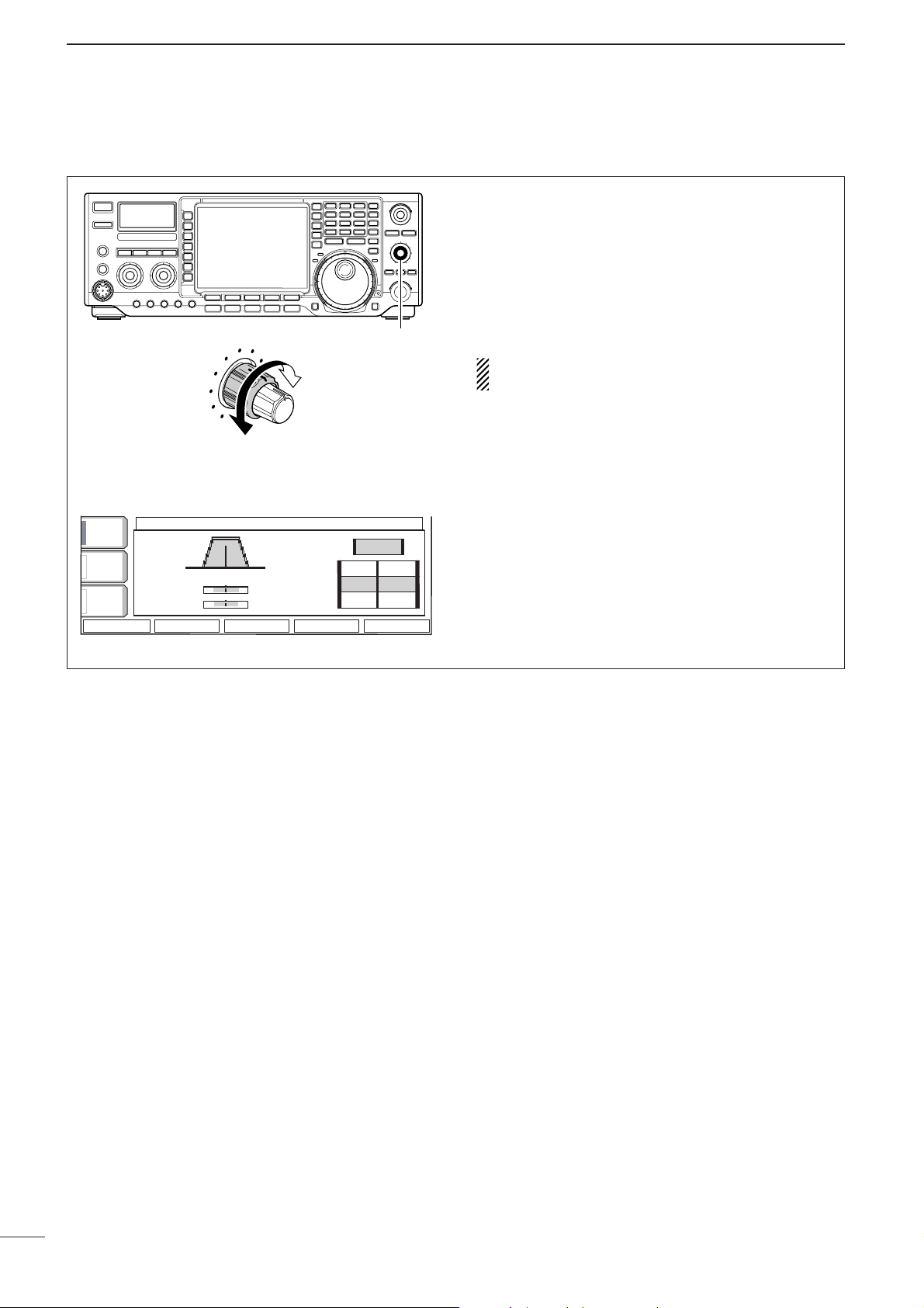
37
4
RECEIVE AND TRANSMIT
DD
About CW pitch control
The received CW audio pitch and monitored CW
audio can be adjusted to suit your preference (300 to
900 Hz in 25 Hz steps) without changing the operating frequency.
➥ Rotate [CW PITCH] to suit your preference.
• Adjustable within 300 to 900 Hz in 25 Hz steps.
The filter set mode screen graphically displays the
CW pitch operations. (See at left.)
FILTER
CW
FI
FI
1.2k
500
250
PBT2
PBT1
450 700 950
BK-IN
OFF
AGC
MID
1/4
OFF
BW
DEF
Lower
frequency
[CW PITCH]
Higher
Frequency
AGC
MID
BK-IN
OFF
1/4
OFF
BW
FILTER
450 700 950
PBT1
PBT2
DEF
FIFIL 1
L 2
FI
L 3
FI
CW
1.2k
500
250
Page 43

38
4
RECEIVE AND TRANSMIT
4
■ Electronic CW keyer
The IC-756PROIII has a number of convenient functions for the electronic keyer that can be accessed
from the memory keyer menu.
q Push [EXIT/SET] several times, if necessary.
w Push [CW/RTTY] to select CW mode.
e Push [(F-3)KEYER] then [EXIT/SET] to select
memory keyer menu screen.
r Push one of the multi-function keys ([F-1] to [F-4])
to select the desired menu. See the diagram
below.
•Push [EXIT/SET] to return to the previous indication.
[CW/RTTY] [EXIT/SET]
[(F-1)]–[(F-4)]
F-1 F-2 F-3 F-4 F-5
BK-INBK-IN
OFFOFF
1/41/4
OFFOFF
AGCAGC
MIDMID
MEMORY KEYERMEMORY KEYER
MEMORY KEYER MENUMEMORY KEYER MENU
SEND Max.55 Characters SEND Max.55 Characters ◊ 4ch 4ch
EDIT Memory Editor EDIT Memory Editor
001 001 Style Contest Number 001 001 Style Contest Number
CW KEY Memo-key,Elec-key,CW Wave Form Set CW KEY Memo-key,Elec-key,CW Wave Form Set
¡Memory keyer menu screen
BK-INBK-IN
OFFOFF
1/41/4
OFFOFF
AGCAGC
MIDMID
MEMORY KEYERMEMORY KEYER
CQ TEST CQ TEST DE ICOM ICOMCQ TEST CQ TEST DE ICOM ICOM
TESTTEST
QRZ?QRZ?
M1M1
M2M2
M3M3
M4M4
CFM TUCFM TU
UR 5NNUR 5NN001001 BK BK
¡Memory keyer send screen
ABCABC
123123
MEMORY KEYERMEMORY KEYER
CQ TEST CQ TEST DE ICOM ICOMCQ TEST CQ TEST DE ICOM ICOM
TESTTEST
QRZ?QRZ?
M1M1
M2M2
M3M3
M4M4
CFM TUCFM TU
UR 5NNUR 5NN001001 BK BK
ABCABC
¡Memory keyer edit screen
KEYER 001KEYER 001
Number StyleNumber Style NormalNormal
CounCount Up Triggert Up Trigger M2M2
Present NumberPresent Number 001001
BK-INBK-IN
OFFOFF
1/41/4
OFFOFF
AGCAGC
MIDMID
¡Contest number set mode
BK-INBK-IN
OFFOFF
1/41/4
OFFOFF
AGCAGC
MIDMID
KEYER CW-KEYKEYER CW-KEY
Keyer Repeat TimeKeyer Repeat Time 2s2s
Dot/Dash RatioDot/Dash Ratio 1:1:3.01:1:3.0
Rise TimeRise Time 4ms4ms
Paddle PolarityPaddle Polarity NormalNormal
Keyer TypeKeyer Type ELEC-KEYELEC-KEY
MIC Up/Down KeyerMIC Up/Down Keyer OFFOFF
¡Keyer set mode screen
F-1 F-2
F-1
F-2
F-3
F-3
F-4
F-4
F-5
21. 085. 0021. 085. 00
1
ANTANT
1
METERMETER
PoPo
P.AMPP.AMP
1
ATTATT
0FF0FF
BK-INBK-IN
OFFOFF
1/41/4
OFFOFF
BWBW
500500
SFTSFT
VFOVFO
FIL2FIL2
12:00
CWCW
qw:pp
AGCAGC
MIDMID
1
21. 085. 0021. 085. 00
TXTX
VFOVFO
USBUSB
FIL2FIL2
CW
CW
CW
CW
BPF
EXIT/SET
SCOPESCOPE
VOICEVOICE
KEYER
MEMORYMEMORY
SCANSCAN
M1M1
M2M2
M3M3
M4M4
-1-1
é
è
DEFDEF
é
è
DEFDEF
ç
å
DELDEL
SPACESPACE
M1..M4M1..M4
SENDSEND
EDITEDIT
001001
CW KEYCW KEY
0
qr.qpp.pp
qr.qpp.pp
Page 44

39
4
RECEIVE AND TRANSMIT
DD
Memory keyer send screen
Pre-set characters can be sent using the keyer send
menu. Contents of the memory keyer are set using
the edit menu.
•Transmitting
q Push [EXIT/SET] several times, if necessary.
w Push [CW/RTTY] to select CW mode.
e Push [(F-3)KEYER] to select the memory keyer
screen.
r Push [TRANSMIT] to set the transceiver to trans-
mit, or set the break-in function ON (p.67).
t Push [(F-1)M1] – [(F-4)M4] momentarily to trans-
mit the contents one time; push these keys for 1
sec. to transmit the contents repeatedly.
• “M1”–“M4” are highlighted while transmitting.
•“ ” appears while transmitting repeatedly.
•
Set the repeat interval of the memory keyer to 1–60 sec.
(1 sec. steps). See p. 42 for keyer set mode.
•To count down the contact number, push [
(F-5)–1].
For your information
When an external keypad is connected to the pin 3
and pin 7 of the [MIC] connecter, the programmed
contents, M1–M4, can be transmitted without opening the memory keyer screen.
See page 104 for details.
y Push [EXIT/SET] twice to exit the memory keyer
screen.
MEMORY KEYER
M1
M2
M3
M4
TEST
TEST
ICOM
ICOM
TEST
QRZ?
CFM
TU
5NN
001
BK
AGC
MID
1/4
OFF
BK-IN
OFF
M1
M2
M3
M4
-1
[TRANSMIT]
AGC
MID
BK-IN
OFF
1/4
OFF
[(F-1)M1]–[(F-4)M4]
[CW/RTTY]
CQCQ TEST
M1
TEST
URUR 5NN
M2
CFM
M3
QRZ?
M4
M1
M2
MEMORY KEYER
CQCQ TEST
001
BK
TU
M3
[EXIT/SET]
DEDE ICOM
M4
ICOM
-1
Page 45

40
4
RECEIVE AND TRANSMIT
DD
Editing a memory keyer
4
The contents of the momory keyer memories can be
set using the memory keyer edit menu. The memory
keyer can memorize and re-transmit 4 CW key codes
for often-used CW sentences, contest number, etc.
Total capacity of the memory keyer is 70 characters
per memory channel.
• Pre-programmed contents
•Programming contents
q Push [EXIT/SET] several times, if necessary.
w Push [CW/RTTY] to select CW mode.
e Push [(F-3)KEYER] then [EXIT/SET] to select
keyer set mode.
r Push [(F-2)EDIT] to enter the keyer edit screen.
t Push [(F-5)M1..M4] several times to select the de-
sired keyer memory channel.
y Select the desired character group by pushing the
character group keys ([ABC], [123] or [etc]) several times.
•[etc] appears when [123] is pushed when “123” char-
acter group is selected.
•Selectabel characters (with the tuning dial);
NOTE:
“^” is used to transmit a following word with no
space such as AR. Put “^” before a text string
such as ^AR, and the string “ ” is sent with
no space.
“✱” is used to insert the CW contest number.
The contest number automatically increments
by 1. This function is only available for one
memory keyer channel at a time. Memory
keyer channel M2 used “✱” by default.
u Select the desired character by rotating the tuning
dial or by pushing the band key for number input.
• Push [(F-1)ΩΩ] or [(F-2)≈≈] for cursor movement.
• Push [(F-3)DEL] to delete the selected character.
• Push [(F-4)SPACE] to input a space.
•“*” is for contact numbers and can be input for the
count up trigger channel (“ ” appears).
i Repeat step u until the desired contents are input.
o Push [(F-5)M1..M4] to select the next memory
channel and repeat step u for character input, if
desired.
!0 Push [EXIT/SET] twice to exit the keyer set mode.
ABC
123
etc
DEL
SPACE
M1..M4
KEYER EDIT
M1
M2
M3
M4
TEST
TEST
ICOM
ICOM
TEST
QRZ?
CFM
TU
5NN
001
BK
ABC
ABC
123
[123]/[etc] [ABC]
Selected
character
Character
group
keys
ABC
123
[(F-3)DEL] [(F-4)SPACE]
[(F-2)≈][(F-1)Ω]
ABC
ç
[EXIT/SET] [(F-5)M1..M4]
KEYER EDIT
CQCQ TEST
TEST
URUR 5NN
CFM
TU
QRZ?
CQCQ TEST
001
BK
DEL
M1
M2
M3
M4
å
DEDE ICOM
SPACE
ICOM
M1..M4
Memory ch
select
CH Contents
M1
CQ TEST CQ TEST DE ICOM ICOM TEST
UR 5NN✽ BK
M2
M3
CFM TU
M4
QRZ?
Key selection
ABC
123
etc
Editable characters
A to Z (capital leters)
0 to 9 (numbers)
/ ? ^ . , @ ✽
AR
Page 46

41
4
RECEIVE AND TRANSMIT
DD
Contest number set mode
CCoouunntt UUpp TTrriiggggeerr
(Count up trigger)
This selects which of the three memory slots will have
the contest serial number exchange. The count up
trigger allows the serial number automatically incremented after each complete serial number exchange
is sent.
• M1, M2, M3 and M4 can be set. (default: M2)
NNuummbbeerr SSttyyllee
(Number style)
This item sets the numbering system used for contest
(serial) numbers— normal or morse cut numbers.
Normal : Does not use morse cut number
(default)
190➜ANO : Sets 1 as A, 9 as N and 0 as O.
190➜ ANT : Sets 1 as A, 9 as N and 0 as T.
90➜ NT : Sets 9 as N and 0 as O.
90➜ NT : Sets 9 as N and 0 as T.
PPrreesseenntt NNuummbbeerr
(Present number)
This item shows the current number for the count up
trigger channel set above.
•Rotate the tuning dial to change the number, or push
[(F-3)001CLR] for 1sec. to reset the current number
to 001.
This menu is used to set the contest (serial) number
and count up trigger, etc.
•Setting the contact (serial) number
Contact number can be automatically transmitted
from one of the memory keyer channels. The Morse
cut numbers can be used as the contact numbers.
The maximum number for contact numbers is 9999.
q Push [EXIT/SET] several times, if necessary.
w Push [CW/RTTY] to select CW mode.
e Push [(F-3)KEYER] then [EXIT/SET] to select
keyer set mode.
r Push [(F-3)001] to select contest number set
mode.
t
Push
[(F-1)YY]
or
[(F-2)ZZ]
to select the desired set
item.
•Push [(F-3)DEF] for 1 sec. to select the default condi-
tion or value.
y Push [EXIT/SET] twice to exit the keyer set mode.
KEYER 001KEYER 001
NumberNumberStyleStyle
NormalNormal
CounCount UPUP TriggerTrigger M2M2
PresentPresentNumberNumber 001001
AGCAGC
MIDMID
1/41/4
OFFOFF
BK-INBK-IN
OFFOFF
é
è
DEFDEF
[(F-2)√][(F-1)∫] [EXIT/SET]
[(F-3)DEF]
Page 47

42
4
RECEIVE AND TRANSMIT
DD
Keyer set mode
KKeeyyeerr RReeppeeaatt TTiimmee
(Keyer repeat time)
When sending CW using the repeat timer, this item
sets the time between transmission.
•1 to 60 sec. in 1 sec. steps can be selected.
•Push [(F-3)DEF] for 1 sec. to select a default setting.
(default: 2 sec.)
DDoott//DDaasshh RRaattiioo
(Dot/Dash ratio)
This item sets the dot/dash ratio.
•1:1:2.8 to 1 : 1 : 4.5 can be set.
• Check the ratio with side tone in CW mode.
•Push [(F-3)DEF] for 1 sec. to select a default ratio
of 1 : 1 : 3.0.
Keying weight example: Morse code “K”
DASH
Weight setting:
1:1:3 (default)
Weight setting:
Adjusted
DASH
DOT (Fixed*)
Adjustable range SPACE (Fixed*)
*SPACE and DOT length can be adjusted with
[KEY SPEED] only.
4
This set mode is used to set the CW side tone, memory keyer repeat time, dash weight, paddle specifica-
tions, keyer type, etc.
•Setting the electronic keyer
q Push [EXIT/SET] several times, if necessary.
w Push [CW/RTTY] to select CW mode.
e Push [(F-3)KEYER] then [EXIT/SET] to select
keyer set mode.
r Push [(F-4)CW KEY] to select memory keyer set
mode.
t Push [(F-1)YY] or [(F-2)ZZ] to select the desired set
item.
y Set the desired condition using the tuning dial.
•Push [(F-3)DEF] for 1 sec. to select a default condition
or value.
u Push [EXIT/SET] twice to normal screen.
DEFDEF
KEYER CW-KEYKEYER CW-KEY
é
è
KeyerKeyer RepeatRepeatTimeTime 2s 2s
Dot/DashDot/DashRatioRatio 1:1:3.01:1:3.0
RiseRise TimeTime 4ms4ms
PaddlePaddlePolarityPolarity NormalNormal
KeyerKeyer TypeType ELEC-KEYELEC-KEY
MICMICUp/DownUp/DownKeyerKeyer OFFOFF
AGCAGC
MIDMID
1/41/4
OFFOFF
BK-INBK-IN
OFFOFF
[(F-2)√][(F-1)∫] [EXIT/SET]
[(F-3)DEF]
Page 48

43
4
RECEIVE AND TRANSMIT
DD
Keyer set mode (continued)
RRiissee TTiimmee
(Rise time)
This item sets the envelop time period which the output power becomes the set transmit power.
•2, 4, 6, or 8 msec. can be selected.
•Push [(F-3)DEF] for 1 sec. to select a default setting.
(default: 4 sec.)
Key action
Tx output power
• About rise time
Rise time
Tx
Rx
Set Tx power level
Time
0
PPaaddddllee PPoollaarriittyy
(Paddle polarity)
This item sets the paddle polarity.
•Normal and reverse pooarity can be selected.
•Push [(F-3)DEF] for 1 sec. to select a default setting.
(default: Normal)
KKeeyyeerr TTyyppee
(Keyer type)
This item selects the keyer type for [ELEC-KEY] con-
nector on the front panel.
•ELEC-KEY, BUG-KEY and Straight key can be selected.
•Push [(F-3)DEF] for 1 sec. to select a default setting.
(default: ELEC-KEY)
MMIICC UUpp//DDoowwnn KKeeyyeerr
(Microphone’s [UP]/[DN] switches keyer)
This item allows you to set the microphone [UP]/[DN]
switches to be used as a paddle.
•ON : [UP]/[DN] switches can be used for CW.
•OFF : [UP]/[DN] switches cannot be used for CW.
•Push [(F-3)DEF] for 1 sec. to select a default setting.
(default: OFF)
NOTE: When “ON” is selected, the frequency and
memory channel cnanot be changed using the
[UP]/[DN] switches.
Page 49

44
4
RECEIVE AND TRANSMIT
4
■ Operating RTTY (FSK)
When using your RTTY terminal or TNC, consult the
manual that comes with the RTTY terminal or TNC.
q Push a band key to select the desired band.
w Push [CW/RTTY] to select RTTY.
•After RTTY mode is selected, push [CW/RTTY] for 1
sec. to toggle between RTTY and RTTY-R modes.
•“RTTY” or “RTTY-R” appears.
e Push [(F-3)DECODE] to display the decoder
screen.
• The IC-756PROIII has a Baudot decoder.
r Rotate the tuning dial to simultaneously tune a de-
sired signal.
•The S-meter indicates received signal strength when
signal is received.
t Push [TRANSMIT] to transmit.
• The TX indicator lights red.
y Type from the connected PC’s keyboard to enter
the contents that you want to transmit.
•The text color will be changed when transmitted.
•Press one of [F-1] to [F-4] to transmit the TX memory
contents.
u Push [TRANSMIT] to return to receive.
[CW/RTTY][AF] Tuning dial
[TRANSMIT] [TX] indicator [RX] indicator Band keys
DD
Convenient functions for receive
•Preamp (p. 57)
➥ Push [P.AMP] several times to set the preamp
OFF, preamp 1 ON or preamp 2 ON.
•“P.AMP1” or “P.AMP2” appears when the preamp 1 or
preamp 2 is set to ON, respectively. (depending on
operating frequency band)
•Attenuator (p. 57)
➥ Push [ATT] several times to set the attenuator in
6 dB steps.
•“ATT” and attenuation level appear when the attenuator is set to ON.
•Noise blanker (p. 64)
➥ Push [NB] switch to turn the noise blanker ON
and OFF.
•Noise blanker indicator (in [NB] switch) lights when
the noise blanker is set to ON.
➥ Push [NB] for 1 sec. to enter the noise blanker
level set mode, then rotate the tuning dial to adjust the threshold level.
•Twin PBT (passband tuning) (p. 60)
➥ Rotate [TWIN PBT] controls (inner/outer).
• Push [PBT CLR] to clear the settings.
•Noise reduction (p. 65)
➥ Push [NR] switch to turn the noise reduction ON
and OFF.
•Rotate [NR] control to adjust the noise reduction level.
•Noise reduction indicator (in [NR] switch) lights when
the noise reduction is set to ON.
•AGC (auto gain control) (p. 59)
➥ Push [AGC] switch several times to select
AGC FAST, AGC MID or AGC SLOW.
➥ Push [AGC] for 1 sec. to enter the AGC set
mode.
• Rotate the tuning dial to adjust the time constant.
•1⁄4 function (p. 27)
➥ Push [1/4] to turn the
1
⁄4 function ON and OFF.
Page 50

DD
RTTY filter/Twin peak filter
45
4
RECEIVE AND TRANSMIT
The transceiver has 5 RTTY filters in addition to normal IF filters. The passband width can be selected
from 1 kHz, 500 Hz, 350 Hz, 300 Hz and 250 Hz.
When the RTTY filter is turned ON, the RTTY tuning
meter can be used. (p. 47)
Moreover, the twin peak filter changes the receive frequency response by boosting 2 particular frequencies
(2125 and 2295 Hz) for better copying of desired RTTY
signals.
q Push [CW/RTTY] once or twice to select RTTY
mode.
w Push [RTTY FIL] to turn the RTTY filter ON.
• “TPF” appears when the twin peak filter is turned ON.
•RTTY filter selection
q Push [EXIT/SET] several times to close a multi-
function screen, if necessary.
w Select RTTY mode.
e Push [RTTY FIL] for 1 sec. to enter RTTY filter set
mode.
r Push [(F-1)YY] to select band width item.
t Rotate the tuning dial to select the RTTY filter
width from 1 kHz, 500 Hz, 350 Hz, 300 Hz and
250 Hz.
•Push [(F-3)DEF] for 1 sec. to select a default value.
y Push [(F-2)ZZ] to select twin peak filter item.
•The received audio volume may become greater when
the twin peak filter is turned ON.
u Rotate the tuning dial to turn the twin peak filter
function ON or OFF.
i Push [EXIT/SET] to exit the RTTY filter set mode.
BWBW
350350
SFTSFT
0
VFOVFO
FIL2FIL2
RTTYRTTY
TXTX
1
CWCW
qr.qpp.pp
21.076.5021.076.50
TPFTPF
METERMETER
PoPo
ANTANT
1
qw:pp
12:0012:00
TPF indicator
[CW/RTTY][RTTY FIL] [EXIT/SET]
DD
About RTTY reverse mode
Received characters are occasionally garbled when
the receive signal is reversed between MARK and
SPACE. This reversal can be caused by incorrect
TNC connections, settings, commands, etc.
To receive a reversed RTTY signal correctly, select
RTTY-R (RTTY Reverse) mode.
q Push [CW/RTTY] once or twice to select RTTY
mode.
w Push [CW/RTTY] for 1 sec. to select RTTY or
RTTY-R mode.
• Check the receive signal.
Normal Reverse
Space
Mark
BFO
Space
Mark
BFO
170 Hz 2125 Hz 170 Hz2125 Hz
Page 51

46
4
RECEIVE AND TRANSMIT
4
DD
Functions for the RTTY decoder indication
The transceiver has an RTTY decoder for Baudot
(mark freq.: 2125 Hz, shift freq.: 170 Hz, 45 bps).
An external terminal unit (TU) or terminal node controller (TNC) is not necessary for receiving a Baudot
signal.
q Push [EXIT/SET] several times to close a multi-
function screen, if necessary.
w Push [CW/RTTY] to select RTTY mode.
e Push [(F-3)DECODE] to turn the RTTY decoder
ON.
•RTTY decoder screen appears.
r If the RTTY filter is turned OFF, push [RTTY FIL]
to turn the function ON.
•The RTTY decoder does not function when the RTTY
filter is turned OFF.
t Push [(F-2)HOLD/CLR] momentarily to freeze the
current screen.
• “HOLD” appears while the function is in use.
y Push [(F-5)WIDE] to toggle the normal or wide
screen space.
u Push [(F-2)HOLD/CLR] for 1 sec. to clear the dis-
played characters.
i Push [EXIT/SET] to exit the RTTY decoder
screen.
SFTSFT
0
BWBW
350 350
RTTY DECODERTTY DECODE
VFOVFO
VFOVFO
qr≥qot≥pp
14.100.00
RTTY RTTY FILFIL2
RTTY RTTY FILFIL2
TXTX
AGCAGC
MIDMID
1/41/4
OFFOFF
RTTYRTTY
FILFIL
ONON
METERMETER
PoPo
P.AMPP.AMP
1
ATTATT
OFFOFF
ANTANT
1
<MENU1><MENU1> TX MEMTX MEM
HLD/CLRHLD/CLR
ADJADJ
WIDEWIDE
qw:pp
12:00
********RTTYRTTY DecodeDecodeMonitorMonitor********
45bps45bps BAUDOTBAUDOTMark=2125,Mark=2125,Shift=170Shift=170
UnShiftUnShift OnOn SpaceSpacesupportsupport(SET-OTHERS)(SET-OTHERS)
NewNewLineLineCodeCodeselectableselectable(SET-OTHERS)(SET-OTHERS)
IfIfRTTY-FILRTTY-FILisisOFF,OFF,PleasePleaseturnturnON.ON.
----------------------------------------------------------------------------------------
CQ CQ CQ THIS IS JA3YUA JA3YUA OSAKA JAPANCQ CQ CQ THIS IS JA3YUA JA3YUA OSAKA JAPAN
CQ CQ CQ THIS IS JA3YUA JA3YUA OSAKA JAPANCQ CQ CQ THIS IS JA3YUA JA3YUA OSAKA JAPAN
CQ CQ CQ THIS IS JA3YUA JA3YUA OSAKA JAPANCQ CQ CQ THIS IS JA3YUA JA3YUA OSAKA JAPAN
THRESHOLDTHRESHOLD 9
AGCAGC
MIDMID
1/41/4
OFFOFF
RTTYRTTY
FILFIL
ONON
<MENU1><MENU1>
HLD/CLRHLD/CLR TX MEMTX MEM
ADJADJ
WIDEWIDE
********RTTYRTTY DecodeDecodeMonitorMonitor********
45bps45bps BAUDOTBAUDOTMark=2125,Mark=2125,Shift=170Shift=170
UnShiftUnShift OnOn SpaceSpacesupportsupport(SET-OTHERS)(SET-OTHERS)
NewNewLineLineCodeCodeselectableselectable(SET-OTHERS)(SET-OTHERS)
IfIfRTTY-FILRTTY-FILisisOFF,OFF,PleasePleaseturnturnON.ON.
----------------------------------------------------------------------------------------
THRESHOLDTHRESHOLD 9
RTTY DECODERTTY DECODE
DD
Setting the decoder threshold level
Adjust the RTTY decoder threshold level if some
characters are displayed when no signal is received.
q Call up the RTTY decoder screen as described
above.
w Push [(F-4)ADJ] to select the threshold level set-
ting condition.
e Rotate the tuning dial to adjust the RTTY decoder
threshold level.
•Push [(F-3)DEF] for 1 sec. to select the default condi-
tion.
r Push [EXIT/SET] to exit the RTTY decoder
screen.
The UnShift On Space (USOS) function and new
line code can be set in the RTTY set mode. (p. 49)
THRESHOLD
9
ADJ
AGC
MID
1/4
OFF
RTTY
FIL
ON
DEF
ADJ
WIDE
****
RTTY
Decode
Monitor
****
45bps
BAUDOT
Mark=2125,
Shift=170
UnShift
Space
support
(SET-OTHERS)
New
Line
Code
selectable
(SET-OTHERS)
RTTY-FIL
OFF,
Please
turn
ON.
--------------------------------------------
RTTY DECODE
AGC
MID
****
RTTY
45bps
RTTY
FIL
ON
1/4
OFF
BAUDOT
UnShift
New
Line
IfIfRTTY-FIL
--------------------------------------------
Decode
Mark=2125,
OnOnSpace
Code
selectable
isisOFF,
ADJ
RTTY DECODE
Monitor
support
Please
THRESHOLD
DEF
****
Shift=170
(SET-OTHERS)
(SET-OTHERS)
turn
ON.
ADJ
WIDE
9
Page 52

47
4
RECEIVE AND TRANSMIT
DD
RTTY memory transmission
Pre-set characters can be sent using the RTTY memory. Contents of the memory are set using the edit
menu.
q Push [EXIT/SET] several times to close a multi-
function screen, if necessary.
w Push [CW/RTTY] to select RTTY mode.
e Push [(F-3)DECODE] to turn the RTTY decoder
ON.
r Push [(F-3)TX MEM] to select RTTY memory
screen.
t Push [(F-5)1-4/5-8] to select memory bank then
push one of the function keys [(F-1)RT1] to [(F-4)
RT4] or [(F-1)RT5] to [(F-4)RT8].
•The selected memory contents will be transmitted immediately.
ANTANT
1
METERMETER
PoPo
P.AMPP.AMP
1
ATTATT
0FF0FF
RTTYRTTY
FILFIL
ONON
1/41/4
OFFOFF
BWBW
350350
SFTSFT
VFOVFO
FIL2FIL2
RTTYRTTY
qw:pp
AGCAGC
MIDMID
1
21. 085. 0021. 085. 00
21. 085. 0021. 085. 00
TXTX
VFOVFO
1
USBUSB
CWCW
CWCW
FIL2FIL2
RT1RT1
RT2RT2
RT3RT3
0
qr.qpp.pp
qr.qpp.pp
12:0012:00
RT4RT4
1-4/5-81-4/5-8
RTTY MEMORYRTTY MEMORY
RT1RT1
RT2RT2
RT3RT3
RT4RT4
DEDE ICOMICOM ICOMICOM K
QSLQSL URUR 599-599599-599 BKBK
QSLQSL DEDE ICOMICOM ICOMICOM URUR 599-599599-599 BKBK
DEDE ICOMICOM ICOMICOM ICOM KICOM K
[(F-1)RT1]–[(F-4)RT4]
[(F-1)RT5]–[(F-4)RT8]
[EXIT/SET] [(F-5)1-4/5-8]
DD
RTTY tuning meter
The transceiver has an RTTY tuning indicator to be
tuned correctly and easily.
The RTTY tuning meter is automatically displayed
when the RTTY filter is turned ON.
q Push [CW/RTTY] to select RTTY mode.
w Push [RTTY FIL] to activate the RTTY filter and
RTTY tuning meter.
SFTSFT
0
FIL2FIL2
RTTYRTTY
TXTX
VFOVFO
USBUSB
USBUSB
USBUSB
FIL2FIL2
qr.qot.pp
qr.wpt.pp
14.100.0014.100.00
14.100.0014.100.00
1
1
VFOVFO
BWBW
350 350
METERMETER
PoPo
P.AMPP.AMP
1
ATTATT
OFFOFF
ANTANT
1
qw:pp
12:00
RTTY tuning meter
Page 53

DD
Editing RTTY memory
48
4
RECEIVE AND TRANSMIT
4
The contents of the RTTY memories can be set using
the memory edit menu. The memory can memorize
and re-transmit 8 RTTY contents for often-used RTTY
sentences. Total capacity of the memory is 70 characters per memory channel.
• Pre-programmed contents
•Programming contents
q Push [EXIT/SET] several times, if necessary.
w Push [CW/RTTY] to select RTTY mode.
e Push [(F-3)DECODE] then [(F-1)MENU1] to select
the RTTY decode menu 2.
r Push [(F-2)EDIT] to enter the RTTY memory edit
screen.
t Push [(F-5)RT1..8] several times to select the de-
sired memory channel.
y Select the desired character group by pushing the
character group keys ([ABC], [123] or [etc]) several times.
•[etc] appears when [123] is pushed when “123” char-
acter group is selected.
•Selectabel characters (with the tuning dial);
u Select the desired character by rotating the tuning
dial or by pushing the band key for number input.
• Push [(F-1)ΩΩ] or [(F-2)≈≈] for cursor movement.
• Push [(F-3)DEL] to delete the selected character.
• Push [(F-4)SPACE] to input a space.
i Repeat step u until the desired contents are input.
o Push [(F-5)RT1..8] to select the next memory
channel and repeat step u for character input, if
desired.
!0 Push [EXIT/SET] to set the contents and exit
RTTY memory edit screen.
Key selection
ABCABC
Editable characters
A to Z (capital leters)
123123
0 to 9 (numbers)
! $ & ? " ' – / . , : ; ( ) ↵
etcetc
CH Contents
↵DE ICOM ICOM K↵
↵DE ICOM ICOM ICOM K↵
↵QSL UR 599–599 BK↵
RT1
RT2
RT3
↵QSL DE ICOM ICOM UR 599–599 BK↵
RT4
↵CQ CQ CQ DE ICOM ICOM ICOM K↵
RT6
RT7
RT8
↵73 GL SK↵
(blank)
(blank)
RT5
RTTY MEMORY EDITRTTY MEMORY EDIT
RT1RT1
RT2RT2
RT3RT3
RT4RT4
QSLQSL URUR 599-599599-599 BKBK
QSLQSL DEDE ICOMICOM ICOMICOM URUR 599-599599-599 BKBK
DEDE ICOMICOM ICOMICOM ICOM KICOM K
ç
å
DELDEL
SPACESPACE RT1..8RT1..8
ABCABC
ABCABC
123123
DEDE ICOMICOM ICOMICOM K
Character
group
keys
Selected
character
Memory ch
select
[(F-2)≈][(F-1)Ω]
[123]/[etc] [ABC]
[EXIT/SET] [(F-5)RT1..8]
[(F-3)DEL] [(F-4)SPACE]
Page 54

49
4
RECEIVE AND TRANSMIT
RRTTTTYY DDeeccooddee UUSSOOSS
This item selects the USOS (UnShift On Space) function of the internal RTTY decoder.
OONN
Decode as letter code
(default)
OOFFFF
Decode as character code
RRTTTTYY TTXX UUSSOOSS
This item selects the FIGS insertion even changing
from LTRS to FIGS does not necessary when sending a numeral or symbol character after a space.
OONN
Inserts FIGS
(default)
OOFFFF
Not insert FIGS
RRTTTTYY DDeeccooddee NNeeww LLiinnee CCooddee
This item selects the new line code of the internal
RTTY decoder.
CR : Carriage Return
LF : Line Feed
CCRR,,LLFF,,CCRR++LLFF
CR, LF and CR+LF
(default)
CCRR++LLFF
CR+LF only
DD
RTTY decoder set mode
This set mode is used to set the decode USOS function, etc.
•Setting the contents
q Push [EXIT/SET] several times, if necessary.
w Push [CW/RTTY] to select RTTY mode.
e Push [(F-3)DECODE] then [(F-1)MENU1] to select
RTTY decode menu 2.
r Push [(F-4)SET] to select RTTY decode set mode.
t Push [(F-1)YY] or [(F-2)ZZ] to select the desired set
item.
y Set the desired condition using the tuning dial.
•Push [(F-3)DEF] for 1 sec. to select a default condition
or value.
u Push [EXIT/SET] to exit from set mode.
DEFDEF
RTTY DECODE SETRTTY DECODE SET
é
è
RTTYRTTY DecodeDecodeUSOSUSOS ONON
RTTYRTTY DecodeDecodeNewNew LineLineCodeCode CR,LF,CR+LFCR,LF,CR+LF
RTTYRTTY TXTX USOSUSOS ONON
AGCAGC
MIDMID
1/41/4
OFFOFF
RTTYRTTY
FILFIL
ONON
[(F-2)√][(F-1)∫] [EXIT/SET]
[(F-3)DEF]
Page 55

50
4
RECEIVE AND TRANSMIT
4
DD
Convenient functions for receive
■ Operating AM
q Push a band key to select the desired band.
w Push [AM/FM] to select AM.
• “AM” indicator appears.
•After AM mode is selected, push [AM/FM] to toggle be-
tween AM and FM modes.
e Rotate the tuning dial to tune a desired frequency.
•The S-meter indicates received signal strength when
signal is received.
r Rotate [AF] to set audio to a comfortable listening
level.
t Push [TRANSMIT] or [PTT] (microphone) to trans-
mit.
• The TX indicator lights red.
y Speak into the microphone at your normal voice
level.
•Adjust the microphone gain with [MIC GAIN] at this step,
if necessary.
u Push [TRANSMIT] or release [PTT] (microphone)
to return to receive.
[TRANSMIT]
[AM/FM]
[AF] [MIC GAIN] Tuning dial
[TX] indicator [RX] indicator Band keys
•Preamp (p. 57)
➥ Push [P.AMP] several times to set the preamp
OFF, preamp 1 ON or preamp 2 ON.
•“P.AMP1” or “P.AMP2” appears when the preamp 1 or
preamp 2 is set to ON, respectively. (depending on
operating frequency band)
•Attenuator (p. 57)
➥ Push [ATT] several times to set the attenuator in
6 dB steps.
•“ATT” and attenuation level appear when the attenuator is set to ON.
•Twin PBT (passband tuning) (p. 62)
➥ Rotate [TWIN PBT] controls (inner/outer).
• Push [PBT CLR] to clear the settings.
•Noise reduction (p. 65)
➥ Push [NR] switch to turn the noise reduction ON
and OFF.
•Rotate [NR] control to adjust the noise reduction level.
•Noise reduction indicator (in [NR] switch) lights when
the noise reduction is set to ON.
•Noise blanker (p. 64)
➥ Push [NB] switch to turn the noise blanker ON
and OFF.
•Noise blanker indicator (in [NB] switch) lights when
the noise blanker is set to ON.
➥ Push [NB] for 1 sec. to enter the noise blanker
level set mode, then rotate the tuning dial to adjust the threshold level.
•Notch filter (p. 64)
➥ Push [NOTCH] switch to turn the auto or manual
notch function ON and OFF.
•Rotate [NOTCH] control to set the attenuating fre-
quency for manual notch operation.
•Notch indicator (in [NOTCH] switch) lights when either
the auto or manual notch is set to ON.
•AGC (auto gain control) (p. 59)
➥ Push [AGC] switch several times to select
AGC FAST, AGC MID or AGC SLOW.
➥ Push [AGC] for 1 sec. to enter the AGC set mode.
• Rotate the tuning dial to adjust the time constant.
DD
Convenient functions for transmit
•Transmit quality monitor (p. 70)
➥ Push [MONITOR] to turn the monitor function ON
and OFF.
•Monitor indicator (in [MONITOR] switch) lights when
the monitor function is set to ON.
➥ Push [EXIT/SET] for 1 sec. then [(F-1)LEVEL] to
enter level set mode. Select the monitor level item
with [(F-1)YY]/[(F-2)ZZ] then rotate the tuning dial
to adjust the monitor gain.
•VOX (voice operated transmit) (p. 66)
➥ Push [VOX] to turn the VOX function ON and
OFF.
•“VOX ON” appears when the VOX function is set to
ON.
•Audio tone control (p. 95)
➥ Push [EXIT/SET] for 1 sec. then [(F-1)LEVEL] to
enter level set mode. Select an item with [(F-
1)YY]/[(F-2)ZZ] then rotate the tuning dial to adjust
the audio tone.
Page 56

51
4
RECEIVE AND TRANSMIT
DD
Convenient functions for receive
■ Operating FM
q Push a band key to select the desired band.
w Push [AM/FM] to select FM.
• “FM” indicator appears.
•After FM mode is selected, push [AM/FM] to toggle be-
tween FM and AM modes.
e Rotate the tuning dial to tune a desired frequency.
•The S-meter indicates received signal strength when
signal is received.
•10 kHz tuning step is preset for FM mode.
r Rotate [AF] to set audio to a comfortable listening
level.
t Push [TRANSMIT] or [PTT] (microphone) to trans-
mit.
• The TX indicator lights red.
y Speak into the microphone at your normal voice
level.
•Adjust the microphone gain with [MIC GAIN] at this step,
if necessary.
u Push [TRANSMIT] or release [PTT] (microphone)
to return to receive.
[TRANSMIT]
[AM/FM][AF] [MIC GAIN] Tuning dial
[TX] indicator [RX] indicator Band keys
•Preamp (p. 57)
➥ Push [P.AMP] several times to set the preamp
OFF, preamp 1 ON or preamp 2 ON.
•“P.AMP1” or “P.AMP2” appears when the preamp 1 or
preamp 2 is set to ON, respectively. (depending on
operating frequency band)
•Attenuator (p. 57)
➥ Push [ATT] several times to set the attenuator in
6 dB steps.
•“ATT” and attenuation level appear when the attenuator is set to ON.
•Notch filter (p. 64)
➥ Push [NOTCH] switch to turn the auto notch func-
tion ON and OFF.
•Rotate [NOTCH] control to set the attenuating fre-
quency for manual notch operation.
•Notch indicator (in [NOTCH] switch) lights when the
auto notch is set to ON.
DD
Convenient functions for transmit
•Transmit quality monitor (p. 70)
➥ Push [MONITOR] to turn the monitor function ON
and OFF.
•Monitor indicator (in [MONITOR] switch) lights when
the monitor function is set to ON.
➥ Push [EXIT/SET] for 1 sec. then [(F-1)LEVEL] to
enter level set mode. Select the monitor level item
with [(F-1)YY]/[(F-2)ZZ] then rotate the tuning dial
to adjust the monitor gain.
•VOX (voice operated transmit) (p. 66)
➥ Push [VOX] to turn the VOX function ON and
OFF.
•“VOX ON” appears when the VOX function is set to
ON.
•Audio tone control (p. 95)
➥ Push [EXIT/SET] for 1 sec. then [(F-1)LEVEL] to
enter level set mode. Select an item with [(F-
1)YY]/[(F-2)ZZ] then rotate the tuning dial to adjust
the audio tone.
Page 57

52
4
RECEIVE AND TRANSMIT
■ Repeater operation
A repeater amplifies received signals and retransmits
them at a different frequency. When using a repeater,
the transmit frequency is shifted from the receive frequency by an offset frequency. A repeater can be accessed using split frequency operation with the shift
frequency set to the repeater’s offset frequency.
For accessing a repeater which requires a repeater
tone, set the repeater tone frequency in set mode
as described below.
q Set the offset frequencies (HF, 50 MHz) and turn
ON the quick split function in set mode (others) in
advance. (p. 69)
w Push [VFO/MEMO] to select VFO mode.
e Push the desired band key.
r Push [AM/FM] several times to select FM mode.
t Set the receive frequency (repeater output fre-
quency).
y Push [SPLIT] for 1 sec. to start repeater operation.
• Repeater tone is turned ON automatically.
•Shifted transmit frequency and “TX” appear in the sub
readout.
•The transmit frequency can be monitored while pushing
[XFC] or using dualwatch.
u Push and hold [PTT] to transmit; release [PTT] to
receive.
i To return to simplex, push [SPLIT] momentarily to
clear the sub display.
BWBW
15k15k
SFTSFT
0
FIL2FIL2
FMFM
VFOVFO
FMFM
USBUSB
USBUSB
FIL2FIL2
wo.yip.pp
wo.tip.pp
14.100.0014.100.00
14.100.0014.100.00
1
1
VFOVFO
SPLITSPLIT
TXTX
TONETONE
TONETONE
ANTANT
1
METERMETER
PoPo
ATTATT
OFFOFF
P.AMPP.AMP
1
qw:pp
12:00
Tone encoder is automatically turned ON.
Shifted frequency appears.
[AM/FM] [XFC]Tuning dial
[VFO/MEMO] [SPLIT] Band keys
DD
Setting the repeater tone
Some repeaters require subaudible tones to be accessed. Subaudible tones are superimposed over
your normal signal and must be set in advance. The
transceiver has 50 tones from 67.0 Hz to 254.1 Hz.
Each memory channel can store an independent setting.
Store repeater tone frequencies and ON/OFF settings
in memory channels for easy recall.
q Select FM mode.
w Push [TONE] for 1 sec. to enter tone set mode.
e Push [(F-1)YY] to select “REPEATER TONE” item.
r Rotate the tuning dial to select the desired re-
peater tone frequency.
t Push [EXIT/SET] to exit tone set mode.
Available repeater tones (Unit: Hz)
T-SCANT-SCAN
é
è
DEFDEF
TONE FREQUENCYTONE FREQUENCY
88.5Hz88.5Hz
88.5Hz88.5HzT-SQL TONET-SQL TONE
REPEATER TONEREPEATER TONE
AGCAGC
FASTFAST
VOXVOX
OFFOFF
TONETONE
OFFOFF
CONVENIENT
[AM/FM][(F-1)Y] [EXIT/SET][TONE] Tuning dial
4
67.0
69.3
71.9
74.4
77.0
79.7
82.5
085.4
088.5
091.5
094.8
097.4
100.0
103.5
107.2
110.9
114.8
118.8
123.0
127.3
131.8
136.5
141.3
146.2
151.4
156.7
159.8
162.2
165.5
167.9
171.3
173.8
177.3
179.9
183.5
186.2
189.9
192.8
196.6
199.5
203.5
206.5
210.7
218.1
225.7
229.1
233.6
241.8
250.3
254.1
Page 58

53
4
RECEIVE AND TRANSMIT
■ Tone squelch operation
The tone squelch opens only when receiving a signal
containing a matching subaudible tone. You can
silently wait for calls from group members using the
same tone.
Available tone squelch tones (Unit: Hz)
q Set the desired frequency band and select FM
mode.
w Push [TONE] several times until “TSQL” appears.
e Push [TONE] for 1 sec. to enter tone set mode.
r Push [(F-2)ZZ] to select the “T-SQL TONE” item.
t Rotate the tuning dial to select the desired tone
squelch frequency.
• Push [(F-3)DEF] for 1 sec. to select the default setting.
y Push [EXIT/SET] to return to the previous indica-
tion.
u When the received signal includes a matching tone,
squelch opens and the signal can be heard.
•When the received signal’s tone does not match, tone
squelch does not open, however, the S-indicator shows
signal strength.
•To open the squelch manually, push [XFC].
i Operate the transceiver in the normal way.
o To cancel the tone squelch, push [TONE] to clear
“TSQL.”
Store tone squelch frequencies and ON/OFF settings
in memory channels for easy recall.
CONVENIENT
T-SCANT-SCAN
é
è
DEFDEF
TONE FREQUENCYTONE FREQUENCY
88.5Hz88.5Hz
88.5Hz88.5HzT-SQL TONET-SQL TONE
REPEATER TONEREPEATER TONE
AGCAGC
FASTFAST
VOXVOX
OFFOFF
TONETONE
OFFOFF
BWBW
15k15k
SFTSFT
0
FIL2FIL2
FMFM
VFOVFO
FMFM
USBUSB
USBUSB
FIL2FIL2
wo.yip.pp
wo.tip.pp
14.100.0014.100.00
14.100.0014.100.00
1
1
VFOVFO
TSQLTSQL
TSQLTSQL
TXTX
ANTANT
1
METERMETER
PoPo
ATTATT
OFFOFF
P.AMPP.AMP
1
qw:pp
12:00
[AM/FM] [XFC]Tuning dial
[VFO/MEMO] [SPLIT] Band keys
67.0
69.3
71.9
74.4
77.0
79.7
82.5
085.4
088.5
091.5
094.8
097.4
100.0
103.5
107.2
110.9
114.8
118.8
123.0
127.3
131.8
136.5
141.3
146.2
151.4
156.7
159.8
162.2
165.5
167.9
171.3
173.8
177.3
179.9
183.5
186.2
189.9
192.8
196.6
199.5
203.5
206.5
210.7
218.1
225.7
229.1
233.6
241.8
250.3
254.1
Page 59

54
4
RECEIVE AND TRANSMIT
■ Data mode (SSTV/PSK31) operation
4
✔
For your information
Carrier point frequency is displayed when SSB data
mode is selected.
See the diagram below for the tone-pair example.
When operating SSTV or PSK31 with your PC software, consult the manual that comes with the software.
q Connect a PC to the transceiver. (p. 19)
w Push a band key to select the desired band.
e Push [SSB] or [AM/FM] to select the desired oper-
ating mode.
r Push the same key for 1 sec. to turn data mode ON.
• “-D” indicator additionally appears.
t Rotate the tuning dial to tune into the desired signal
and decoded correctly.
• Also use the tuning indicator of the software.
• During SSB data mode,
1
⁄4 tuning function can be used
for critical tuning.
y Operate the PC (software) to transmit.
•When operating in SSB data mode, adjust the AF output
level from PC so that the ALC meter reading doesn’t go
outside the ALC zone.
NOTE: When SSB data mode is selected, the audio
input from the [ACC(1)] (pin 6) is used for transmission instead of [MIC]’s.
The fixed condition is used for SSB data transmission as follow.
• [COMP] : OFF
• Tx bandwidth : MID
• Tx Tone (Bass) : 0
• Tx Tone (Trebles) : 0
[TRANSMIT]
[TX] indicator [RX] indicator Band keys
[AM/FM][AF] [MIC GAIN] Tuning dial
2325 Hz
200 Hz 2125 Hz
Carrier point
(displayed frequency)
Page 60

DMini scope screen
■ Spectrum scope screen
This function allows you to display the relative
strengths of signals around the center frequency. The
span can be set to ±12.5 kHz, ±25 kHz, ±50 kHz and
±100 kHz. Ideal for monitoring band conditions in an
instant.
q Push [EXIT/SET] several times to close a multi-
function screen, if necessary.
w Push [(F-1)SCOPE] to select the scope screen.
e Push [(F-1)SPAN] several times to select the scope
span.
r Push [(F-2)ATT] several times to activate an atten-
uator or turn the attenuator OFF.
• 10, 20 and 30 dB attenuators are available.
t Push [(F-3)MARKER] several times to select the
marker (sub readout or transmit frequency) or turn
the marker OFF.
•“TX MARKER” displays the marker at the transmit frequency.
•“SUB MARKER” displays the marker at the sub readout
frequency.
y Push [(F-4)HOLD] to freeze the current spectrum
waveform.
• “HOLD” appears while the function is in use.
u Push [EXIT/SET] to exit the scope screen.
If a strong signal is received, a ghost waveform may
appear. Push [(F-2)ATT] several times to activate
the spectrum scope attenuator in this case.
BW
2.4k
SFT
FIL2
USB
TX
VFO
USB
USB
USB
FIL2
14.100.00
14.100.00
VFO
SUB
MARKER
ATT
10dB
HOLD
Grid
2.5k
10dB
+12.5k
-12.5k
SPECTRUM SCOPE
ANT
METER
Po
ATT
OFF
VOX
OFF
COMP
OFF
WIDE
AGC
MID
P.AMP
HOLD
SET
SPAN
ATT
MARKER
5
55
FUNCTION FOR RECEIVE
This mini scope screen can be displayed with another
screen indication, such as set mode menu, decoder
screen, memory list screen, etc. simultaneously.
➥ Push [MAIN/SUB•M.SCOPE] for 1 sec. to toggle
the mini scope indication ON and OFF.
**** RTTY Encode/Decode Monitor **** **** RTTY Encode/Decode Monitor ****
45bps BAUDOT Mark=2125Hz, Shift=170Hz 45bps BAUDOT Mark=2125Hz, Shift=170Hz
Max.62 Charascters x 8ch TX Memory Max.62 Charascters x 8ch TX Memory
If RTTY-FIL is OFF, Please turn ON. If RTTY-FIL is OFF, Please turn ON.
ANTANT
1
METERMETER
PoPo
P.AMPP.AMP
1
ATTATT
OFFOFF
AGCAGC
MIDMID
RTTYRTTY
FILFIL
ONON
1/41/4
OFFOFF
RTTY DECODERTTY DECODE
BWBW
350350
SFTSFT
0
VFOVFO
VFOVFO
wq≥qpp≥pp
14.100.0014.100.00
RTTY RTTY FIL2FIL2
SSBSSB
FIL2FIL2
TXTX
THRESHOLDTHRESHOLD 9 9
<MENU1><MENU1>
HLD/CLRHLD/CLR
TX MEMTX MEM
ADJADJ
WIDEWIDE
qw:pp
12:00
Grid
2.5k
10dB
+ 12.5k
- 12.5k
SPECTRUM SCOPE
[MAIN/SUB•M.SCOPE]
ANT
1
METER
Po
P.AMP
1
ATT
OFF
AGC
MID
VOX
OFF
COMP
OFF
WIDE
SPAN
[(F-3)MARKER]
[(F-2)ATT][(F-1)SPAN] [EXIT/SET]
2.4k
BW
VFO
TX
qr.qot.pp
1
VFO
-12.5k
Grid
2.5k
10dB
ATT
10dB
SUB
MARKER
HOLD
0
SFT
USB
FIL2
14.100.00
USB
FIL2
qr.wpq.pp
14.100.00
1
ATT
SPECTRUM SCOPE
MARKER
USB
USB
HOLD
[(F-4)HOLD]
[(F-5)SET]
qw:pp
12:00
+12.5k
SET
Appears when the
marker is out of range.
Sub readout
or TX marker
Appears when the
marker is out of range.
Page 61

56
4
FUNCTION FOR RECEIVE
5
DScope set mode
The spectrum scope shows the transmit signal waveform while transmitting. This can be deactivated if desired.
The spectrum scope shows the transmit signal waveform while transmitting. This can be deactivated if desired.
When “OFF” is selected, the spectrum scope holds
the received waveform while transmitting and does
not show the transmit waveform.
q During spectrum scope indication ON, push [(F-5)
SET] to select scope set mode screen.
w Push [(F-5)SET] to select the spectrum scope set
mode.
e Push [(F-1)YY] or [(F-2)ZZ] to select the desired set
item.
r Rotate the tuning dial to select the desired condi-
tion.
•Push [(F-3)DEF] for 1 sec. to select a default condition.
t Push [EXIT/SET] to exit spectrum scope set
mode.
DEFDEF
é
è
VOXVOX
OFFOFF
COMPCOMP
OFFOFF
WIDEWIDE
AGCAGC
MIDMID
ScopeScope duringduringTxTx ONON
MaxMaxHoldHold ONON
SCOPESCOPE SETSET
[(F-2)Z][(F-1)Y] [EXIT/SET] [(F-3)DEF]
SSccooppee dduurriinngg TTxx
Turn the transmitting signal waveform indication ON
and OFF.
When “OFF” is selected, the spectrum scope holds
the received waveform while transmitting and does
not show the transmit waveform. (default: ON)
MMaaxx HHoolldd
Turn the peak level holding function ON and OFF.
(default: ON)
Page 62
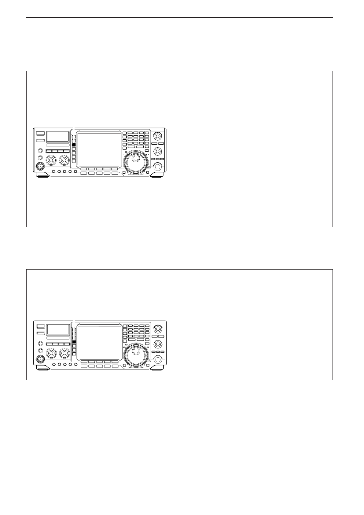
57
5
FUNCTION FOR RECEIVE
■ Preamplifier
The preamp amplifies received signals in the front
end circuit to improve the S/N ratio and increase the
sensitivity. Set this to preamp 1 or preamp 2 when receiving weak signals.
➥ Push [P.AMP] several times to set the preamp
OFF, preamp 1 ON or preamp 2 ON.
•“P. AMP1” activates 10 dB preamp for HF all bands.
•“P. AMP2” activates 16 dB high-gain preamp for
24 MHz band and above.
Regarding the use of the “P.AMP 2”
(Pre-amplifier 2)
The “P.AMP 2” is a high gain receive amplifier. When
the “P.AMP 2” is used during times of strong electric
fields, distortion sometimes results. In such cases,
use the transceiver with the “P.AMP 1” or “P.AMP
OFF” setting.
The “P.AMP 2” is most effective when:
•Used on bands above 24 MHz and when electric
fields are weak.
•Receive sensitivity is insufficient during low gain, or
while using a narrow band antenna (such as small
loop, a Beverage antenna or a short Yagi antenna,
etc.) is used.
[P.AMP]
■ Attenuator
The attenuator prevents a desired signal from distortion when very strong signals are near the desired frequency or when very strong electric fields, such as
from broardcasting stations, are near your location.
➥ Push [ATT] several times to set the attenuator 6
dB, 12 dB, 18 dB or OFF.
•“ATT 6dB,” “ATT 12dB,” “ATT 18dB” and “ATT OFF” appears respectively.
[ATT]
Page 63

58
5
FUNCTION FOR RECEIVE
5
■ RIT function
The RIT (Receive Increment Tuning) function compensates for off-frequencies of the communicating
station.
The function shifts the receive frequency up to ±9.999
kHz in 1 Hz steps (10 Hz steps when cancelling the 1
Hz step readout) without moving the transmit frequency.
• See #1 on p. 5 for function description.
q Push [RIT] to turn the RIT function ON and OFF.
•“ ” and the shifting frequency appear when the
function is ON.
w Rotate the [RIT/∂∂TX] control.
e To reset the RIT frequency, push [CLEAR] for
1 sec.
•Push [CLEAR] momentarily to reset the RIT frequency
when the quick RIT/∂TX clear function is ON. (p. 103)
r To cancel the RIT function, push [RIT] again.
•“ ” disappears.
RIT
BW
2.4k
SFT
FIL2
USB
TX
USB
14.100.00
VFO
ANT
METER
Po
P.AMP
BW
2.4k
SFT
FIL2
USB
TX
USB
14.100.00
VFO
ANT
METER
Po
P.AMP
RIT
When RIT and ∂TX are ON at the same time, the
[RIT/∂∂TX] control shifts both the transmit and receive frequencies from the displayed frequency at
the same time.
•Calculate function
The shift frequency of the RIT (or ∂TX) function can
be added/subtracted to the displayed frequency.
While displaying the RIT (and/or ∂TX) shift frequency, push [RIT] (or [∂∂TX]) for 1 sec.
•Practical example
When you find a DX station on 21.025 MHz/CW and
the station is picking up stations transmitting slightly
up from 21.025 MHz.
q Push [RIT] and [∂∂TX] to turn both the RIT and
∂TX functions ON.
w Rotate [RIT/∂∂TX] to find the DX station’s receive
frequency.
e When you find the DX station’s receive frequency,
push [RIT] to turn the RIT function OFF.
•Now you can transmit the DX station’s receive frequency and receive the DX station’s transmit frequency (21.025 MHz).
r Start transmitting while the station is standing by.
BWBW
2.4k2.4k
SFTSFT
0
FIL2FIL2
USBUSB
TXTX
USBUSB
qr.qot.pp
14.100.0014.100.00
p.wt
RIT
BWBW
2.4k2.4k
SFTSFT
0
FIL2FIL2
USBUSB
TXTX
USBUSB
qr.qot.wt
14.100.0014.100.00
p.pp
RIT
1
VFOVFO
1
VFOVFO
ANTANT
1
METERMETER
PoPo
P.AMPP.AMP
1
ANTANT
1
METERMETER
PoPo
P.AMPP.AMP
1
qw:pp
12:00
qw:pp
12:00
Push and hold
RIT
[CLEAR]
[RIT/∂TX][RIT]
RIT
ANT
1
METER
Po
P.AMP
1
2.4k
BW
VFO
TX
qr.qot.pp
1
SFT
0
USB
14.100.00
FIL2
USB
RIT
q.wt
qw:pp
12:00
Appear
RIT/∂TX
Low shift High shift
ANT
1
METER
Po
P.AMP
1
2.4k
BW
VFO
TX
qr.qot.pp
1
SFT
0
USB
14.100.00
FIL2
USB
RIT
qw:pp
12:00
p.pp
Reset to
“0.00”
RIT
Page 64

59
5
FUNCTION FOR RECEIVE
■ AGC function
The AGC (auto gain control) controls receiver gain to
produce a constant audio output level even when the
received signal strength is varied by fading, etc.
The transceiver has 3 AGC characteristics (time constant; fast, mid, slow) for non-FM mode.
The FM mode AGC time constant is fixed as ‘FAST’
(0.1 sec.) and AGC time constant cannot be selected.
[AGC]
[EXIT/SET][(F-3)DEF]
•AGC time constant selection
q Select non-FM mode.
w Push [AGC] several times to select AGC fast, AGC
medium (MID) or AGC slow.
•Selectable AGC time constant (unit: sec.)
•Setting the AGC time constant
q Select the desired mode other than FM mode.
w Push [AGC] for 1 sec. to enter AGC set mode.
e Push [AGC] several times to select FAST time
constant.
r Rotate the tuning dial to set the desired time con-
stant for ‘AGC FAST.’
•AGC time constant can be set between 0.1 to 8.0 sec.
(depends on mode) or turned OFF.
•Push [(F-3)DEF] for 1 sec. to select a default value.
t Push [AGC] to select medium time constant.
y Rotate the tuning dial to set the desired time con-
stant for ‘AGC MID.’
•AGC time constant can be set between 0.1 to 8.0 sec.
(depends on mode) or turned OFF.
•Push [(F-3)DEF] for 1 sec. to select a default value.
u Push [AGC] to select slow time constant.
i Rotate the tuning dial to set the desired time con-
stant for ‘AGC SLOW.’
•AGC time constant can be set between 0.1 to 8.0 sec.
(depends on mode) or turned OFF.
•Push [(F-3)DEF] for 1 sec. to select a default value.
o Select another mode other than FM. Repeat steps
e to i if desired.
!0 Push [EXIT/SET] to exit the AGC set mode
screen.
DEFDEF
SFTSFT
0
FIL2FIL2
USBUSB
TXTX
VFOVFO
USBUSB
USBUSB
USBUSB
FIL2FIL2
qr.qot.pp
qr.wpt.pp
14.100.0014.100.00
14.100.0014.100.00
1
1
VFOVFO
BWBW
2.4k2.4k
AGCAGC
(sec)(sec)
FMFM
AMAM
0.10.1
3.03.0
5.05.0
7.07.0
1.21.2
0.50.5
0.10.1
0.10.1
0.30.3
2.02.0
6.06.0
0.50.5
1.21.2
------
------
SSBSSB
FASTFAST
SLOWSLOW
MIDMID
CWCW RTTYRTTY
ANTANT
1
COMPCOMP
OFFOFF
WIDEWIDE
METERMETER
PoPo
P.AMPP.AMP
1
AGCAGC
MIDMID
ATTATT
OFFOFF
VOXVOX
OFFOFF
qw:pp
12:00
Medium AGC time constant
Slow AGC time constant
Fast AGC time constant
AGC
MID
AGC
SLOW
AGC
FAST
Mode Default Selectable AGC time constant
0.3 (FAST)
OFF, 0.1, 0.2, 0.3, 0.5, 0.8, 1.2,
SSB 2.0 (MID)
1.6, 2.0, 2.5, 3.0, 4.0, 5.0, 6.0
6.0 (SLOW)
0.1 (FAST)
OFF, 0.1, 0.2, 0.3, 0.5, 0.8, 1.2,
CW 0.5 (MID)
1.6, 2.0, 2.5, 3.0, 4.0, 5.0, 6.0
1.2 (SLOW)
0.1 (FAST)
OFF, 0.1, 0.2, 0.3, 0.5, 0.8, 1.2,
RTTY 0.5 (MID)
1.6, 2.0, 2.5, 3.0, 4.0, 5.0, 6.0
1.2 (SLOW)
3.0 (FAST)
OFF, 0.3, 0.5, 0.8, 1.2, 1.6, 2.0,
AM 5.0 (MID)
2.5, 3.0, 4.0, 5.0, 6.0, 7.0, 8.0
7.0 (SLOW)
FM 0.1 (FAST) Fixed
Page 65

60
5
FUNCTION FOR RECEIVE
5
■ Twin PBT operation
General PBT (Passband Tuning) function electronically
narrows the IF passband width by shifting the IF frequency to slightly outside of the IF filter passband to
reject interference. This transceiver uses the DSP circuit for the PBT function. Moving both [TWIN PBT]
controls to the same position shifts the IF.
➥ The LCD shows the passband width and shift fre-
quency graphically.
➥ Push [FILTER] for 1 sec. to enter the filter set
mode. Current passband width and shift frequency
is displayed in the filter set mode screen.
➥ To set the [TWIN PBT] controls to the center posi-
tions, push [PBT CLR] for 1 sec.
The variable range depends on the passband width
and mode. The edge of the variable range is half of the
passband width, and PBT is adjustable in 25 or 50 Hz
steps. These controls function as an IF shift control
while in AM mode and when the RTTY filter is turned
ON. Only the inner control may function in this case.
IF shift is adjustable in 20/40 Hz steps in RTTY (RTTY
filter is turned ON) or 150/300/500 Hz steps in AM.
•[TWIN PBT] should normally be set to the center posi-
tions (PBT setting is cleared) when there is no interference.
•When PBT is used, the audio tone may be changed.
• Not available for FM mode.
•While rotating [TWIN PBT], noise may occur. This comes
from the DSP unit and does not indicate an equipment
malfunction.
SFT
FIL2
USB
TX
VFO
USB
USB
USB
FIL2
14.100.00
14.100.00
VFO
BW
2.4k
ANT
METER
Po
P.AMP
ATT
OFF
PBT OPERATION EXAMPLE
TWIN PBT TWIN PBT TWIN PBT
IF center frequency Interference Desired signal
Passband
Both controls at
center position
Cutting a lower
passband
Cutting both higher and
lower passbands
Interference Interference
Desired signal
Passband
[TWIN PBT]
[PBT CLR][FILTER]
Shows filter width, shifting value and condition
ANT
METER
P.AMP
ATT
OFF
2.4k
BW
1
Po
1
VFO
TX
qr.qot.pp
1
VFO
SFT
USB
0
USB
14.100.00
qr.wpt.pp
14.100.00
1
FIL2
FIL2
USB
USB
qw:pp
12:00
Page 66

61
5
FUNCTION FOR RECEIVE
■ IF filter selection
The transceiver has 3 passband width IF filters for
each mode.
For SSB and CW modes, the passband width can be
set within 50 to 3600 Hz in 50 or 100 Hz steps. A total
of 41 passband widths are available.
For RTTY mode, the passband width can be set within
50 to 2700 Hz in 50 or 100 Hz steps. A total of 32
passband widths are available.
For AM and FM modes, the passband width is fixed
and 3 passband widths are available.
The filter selection is automatically memorized in
each mode.
The PBT shift frequencies are automatically memorized in each filter.
•IF filter selection
q Select the desired mode.
w For RTTY mode, turn OFF the RTTY filter by push-
ing [RTTY FIL].
e Push [FILTER] several times to select the IF filter
1, 2 or 3.
•The selected passband width and filter number is dis-
played in the LCD.
•Filter passband width setting
(SSB, CW and RTTY mode only)
q Select SSB, CW or RTTY mode.
•Passband widths for AM and FM modes are fixed and
cannot be set.
w For RTTY mode, turn OFF the RTTY filter by push-
ing [RTTY FIL].
e Push [FILTER] for 1 sec. to enter filter set mode.
r Push [FILTER] several times to select the desired
IF filter.
t While pushing [(F-1)BW], rotate the tuning dial to
set the desired passband width.
•The passband width can be set within the range as
shown right table.
•Push [(F-3)DEF] for 1 sec. to select the default value.
y Repeat steps r to t if desired.
u Push [EXIT/SET] to exit the filter set mode screen.
The PBT shift frequencies are cleared when the
passband width is changed.
This filter set mode screen graphically displays the
PBT shift frequencies and CW pitch operations.
*: When the IF filter is selected FIL2 or FIL3 in the FM
mode operation, the Tx IF filter’s passband width is
fixed narrow selection (2.5 kHz).
FIL1
Mode Filter Default Range (Steps)
3.0 kHz
1.8 kHz
2.4 kHz
1.2 kHz
250 Hz
7.0 kHz
500 Hz
2.4 kHz
250 Hz
500 Hz
9.0 kHz
3.0 kHz
6.0 kHz
10 kHz
Fixed
Fixed
15 kHz
50–500 Hz (50 Hz)/
600–3.6 kHz (100 Hz)
50–500 Hz (50 Hz)/
600–3.6 kHz (100 Hz)
50–500 Hz (50 Hz)/
600–2.7 kHz (100 Hz)
FIL2
SSB
RTTY
AM
FM*
SSB-D
CW
FIL3
FIL1
FIL2
FIL3
FIL1
FIL2
FIL3
FIL1
FIL2
FIL3
FIL1
FIL2
FIL3
BWBW
DEFDEF
SFTSFT
0
FIL2FIL2
USBUSB
TXTX
VFOVFO
USBUSB
USBUSB
USBUSB
FIL2FIL2
qr.qot.pp
qr.wpt.pp
14.100.0014.100.00
14.100.0014.100.00
1
1
VFOVFO
BWBW
2.4k2.4k
FILTERFILTER
SSBSSB
FIFIL 1
FIFIL 2
FIFIL 3
3.0k3.0k
2.4K2.4K
1.8K1.8K
PBT2PBT2
PBT1PBT1
300300 15001500 27002700
ANTANT
1
COMPCOMP
OFFOFF
WIDEWIDE
METERMETER
PoPo
P.AMPP.AMP
1
AGCAGC
MIDMID
ATTATT
OFFOFF
VOXVOX
OFFOFF
qw:pp
12:00
Passband
width
Selected
IF filter
[FILTER]
Page 67

62
5
FUNCTION FOR RECEIVE
■ DSP filter shape
The type of DSP filter shape for each SSB and CW
can be selected independently from soft and sharp.
q Push [EXIT/SET] several times to close a multi-
function screen, if necessary.
w Push [EXIT/SET] switch for 1 sec. to enter set
mode.
e Push [(F-3)DSP] to enter the DSP filter set mode.
r Push one of [(F-2)SSB-FIL] or [(F-4)CW-FIL] to
select the desired DSP filter shape from sharp and
soft for each SSB or CW mode, respectively.
t Push [EXIT/SET] twice to exit the set mode.
AGCAGC
MIDMID
BK-INBK-IN
OFFOFF
1/41/4
OFFOFF
DSP FILTER SET
SSBSSB
SHARPSHARP CWCW
SHARPSHARP
SSB-FILSSB-FIL CW-FILCW-FIL
SSBSSB
SOFTSOFT CWCW SOFTSOFT
F-4
Push
F-2
Push
[EXIT/SET][(F-3)DSP][(F-2)SSB-FIL] [(F-4)CW-FIL]
5
Page 68

63
5
FUNCTION FOR RECEIVE
■ Dualwatch operation
Dualwatch monitors 2 frequencies with the same mode
simultaneously.
During dualwatch, both frequencies should be on the
same band, because the bandpass filter in the RF circuit is selected for the main readout frequency.
RIT function can be used for the main readout only.
∂TX function can be used for the transmit readout
(main readout when the split function is OFF; sub
readout when the split function is ON).
q Set a desired frequency.
w Push [DUALWATCH] for 1 sec.
•Equalized receive frequency and “ ” appear in
the LCD. This quick dualwatch function can be turned
OFF in set mode. (p. 100)
•Pushing [DUALWATCH] momentarily activates the du-
alwatch with the previously operated frequency.
e Set another desired frequency using the tuning dial.
r Adjust [BAL] to set a suitable signal strength bal-
ance between the main and sub readout frequencies.
• S-meter shows the combined signal strength.
t To transmit on the sub readout frequency, push
[CHANGE] or [SPLIT].
BWBW
2.4k2.4k
SFTSFT
0
FIL2FIL2
USBUSB
VFOVFO
TXTX
5656
1
USBUSB
USBUSB
USBUSB
FIL2FIL2
wq.wop.pp
wq.wop.pp
14.100.0014.100.00
14.100.0014.100.00
VFOVFO
DUAL-WDUAL-W
ANTANT
1
METERMETER
PoPo
P.AMPP.AMP
1
ATTATT
OFFOFF
qw:pp
12:00
DUAL-W
•Scanning during dualwatch
Scanning operates only for the main readout. To operate the scan during dualwatch, scan on the main
readout and use the sub readout for your QSO using
both dualwatch and split frequency operation.
q Program the desired programmed scan edges in
the same amateur band. See p. 79 for programming.
•If you plan to operate a ∂F scan, programming the
scan edges may not be necessary.
w Push [SPLIT] to turn the split frequency function
ON.
•“ ” appears.
e Select VFO mode for the main readout.
r Set the desired operating frequency for the main
readout.
t Push [DUALWATCH] for 1 sec.
•The main and sub readout frequencies are equalized
and the dualwatch function is turned ON.
y Push [(F-5)SCAN] to select the scan screen.
•Push [EXIT/SET] several times to close a multi-func-
tion screen, if necessary.
u Push [(F-1)PROG] or [(F-2)∂∂F] to start the pro-
grammed scan or ∂F scan, respectively.
•Scan activates on the main readout between the programmed scan edges or within the ∂F span.
•Transmitting on the sub readout stops the scan.
i To cancel the scan, push [EXIT/SET].
wq.wop.pp
BWBW
2.4k2.4k
SFTSFT
0
FIL2FIL2
USBUSB
VFOVFO
USBUSB
USBUSB
USBUSB
FIL2FIL2
wq.wtp.pp
14.100.0014.100.00
14.100.0014.100.00
VFOVFO
SPLITSPLIT
1
1
DUAL-WDUAL-W
PROGPROG
∂
F
FINEFINE
∂
F SPANF SPAN
SETSET
SCANSCAN
TXTX
ANTANT
1
COMPCOMP
OFFOFF
WIDEWIDE
METERMETER
PoPo
P.AMPP.AMP
1
AGCAGC
MIDMID
ATTATT
OFFOFF
VOXVOX
OFFOFF
qw:pp
12:00
PROGRAM SCANPROGRAM SCAN
∂ F SpanSpan: ±±10kHz10kHz
ProgrammedProgrammed P1:P1: 21.000.00MHz21.000.00MHz
scanscan edgesedgesP2:P2:21.450.00MHz21.450.00MHz
wq.wop.pp
BWBW
2.4k2.4k
SFTSFT
0
FIL2FIL2
USBUSB
VFOVFO
USBUSB
USBUSB
USBUSB
FIL2FIL2
wq.wop.pp
14.100.0014.100.00
14.100.0014.100.00
VFOVFO
SPLITSPLIT
1
1
DUAL-WDUAL-W
TXTX
ANTANT
1
METERMETER
PoPo
P.AMPP.AMP
1
ATTATT
OFFOFF
qw:pp
qw:pp
BWBW
2.4k2.4k
SFTSFT
0
FIL2FIL2
USBUSB
VFOVFO
USBUSB
USBUSB
USBUSB
FIL2FIL2
wq.wop.pp
14.100.0014.100.00
14.100.0014.100.00
VFOVFO
qr.wpt.pp
SPLITSPLIT
1
1
TXTX
ANTANT
1
METERMETER
PoPo
P.AMPP.AMP
1
ATTATT
OFFOFF
qw:pp
12:00
SPLIT
[BAL] [CHANGE][DUALWATCH] [SPLIT]
DUAL-W
SPLIT
Page 69

64
5
FUNCTION FOR RECEIVE
■ Notch function
This transceiver has auto and manual notch functions. The auto notch function automatically attenuates more than 3 beat tones, tuning signals, etc.,
even if they are moving. The manual notch can be set
to attenuate a frequency via the [NOTCH] control.
➥ Push [NOTCH] to toggle the notch function be-
tween auto, manual and OFF in SSB and AM
modes.
➥ Push [NOTCH] to turn the manual notch function
ON and OFF in CW mode.
➥ Push [NOTCH] to turn the auto notch function ON
and OFF in FM mode.
•Set to attenuate a frequency for manual notch via the
[NOTCH] control.
• “AN” appears when auto notch is in use.
• “MN” appears when manual notch is in use.
While operating the manual notch, noise may be
heard. This comes from the DSP unit and does not
indicate an equipment malfunction.
Unwanted tone
frequency
Desired
signal (AF)
Desired
signal (AF)
Particular frequency
is attenuated
Auto notch OFF Auto notch ON
[NOTCH](control)[NOTCH](switch)
■ Noise blanker
The noise blanker eliminates pulse-type noise such
as from car ignitions. The noise blanker is not available for FM mode.
q Push [NB] to turn the noise blanker ON.
• [NB] indicator lights.
w Push [NB] for 1 sec. to enter the noise blanker
level set mode.
e Rotate the tuning dial to adjust the noise blanker
level.
• Push [(F-3)DEF] for 1 sec. to return to default value.
r Push [NB] to turn the noise blanker OFF.
• [NB] indicator goes off.
When using the noise blanker, received signals
may be distorted if they are excessively strong.
VOX
ON
COMP
OFF
WIDE
AGC
MID
NB
NB Level
50%
DEF
5
[NB] Tuning dial[(F-3)DEF]
DEF
NB
50%
AGC
MID
VOX
ON
COMP
OFF
WIDE
NB Level
Page 70

65
5
FUNCTION FOR RECEIVE
■ Dial lock function
The dial lock function prevents changes by accidental
movement of the tuning dial. The lock function electronically locks the dial.
➥ Push [LOCK/SPEECH] to toggle the dial lock func-
tion ON and OFF.
•The [LOCK] indicator lights when the dial lock function
is in use.
[LOCK] indicator
[LOCK/SPEECH] switch
■ Noise reduction
The noise reduction function reduces noise components and picks out desired signals which are buried
in noise. The received signals are converted to digital
signals and then the desired signals are separated
from the noise.
q Push the [NR] switch to turn the noise reduction
ON.
• [NR] indicator lights.
w Rotate the [NR] control to adjust the noise reduc-
tion level.
e Push the [NR] switch to turn the noise reduction
OFF.
• [NR] indicator lights off.
Deep rotation of the [NR] control results in audio
signal masking or distortion. Set the [NR] control
for maximum readability.
Noise reduction OFF Noise reduction activated
Desired
signal (CW)
Noise components
BAL NR
OFF
BAL NR
[NR](control) [NR](switch)
Page 71

DAdjusting the VOX function
DUsing the VOX function
6
66
FUNCTION FOR TRANSMIT
■ VOX function
q Select a phone mode (SSB, AM, FM).
w Push [VOX] to turn the VOX function ON or OFF.
• “VOX ON” appears while the VOX is in use.
[VOX]
q Select a phone mode (SSB, AM, FM).
w Push [VOX] to turn VOX function ON.
e Push [VOX] for 1 sec. to enter VOX set mode.
r Select the VOX gain item using [(F-1)YY] or [(F-
2)ZZ].
t While speaking into the microphone, rotate the
tuning dial to the point where the transceiver is
continuously transmitting.
y Adjust the VOX delay for a convenient interval be-
fore returning to receive.
- Select the VOX delay item using [(F-1)YY] or [(F-2)ZZ].
- Rotate the tuning dial.
u If the receive audio from the speaker switches to
transmit, adjust the anti VOX to the point where it
has no effect.
BWBW
2.4k2.4k
SFTSFT
0
FIL2FIL2
USBUSB
TXTX
VFOVFO
USBUSB
USBUSB
USBUSB
FIL2FIL2
qr.qot.pp
qr.wpt.pp
14.100.0014.100.00
14.100.0014.100.00
1
1
VFOVFO
é
è
DEF
VOX
ANTANT
1
COMPCOMP
OFFOFF
WIDEWIDE
METERMETER
PoPo
P.AMPP.AMP
1
AGCAGC
MIDMID
ATTATT
OFFOFF
VOXVOX
OFFOFF
qw:pp
12:00
VOXGain 50%
Anti-VOX 50%
VOXDelay 0.2s
[VOX]
The VOX (Voice-Operated Transmission) function
switches between transmit and receive with your voice.
This function provides an opportunity to input log entries into your computer, etc., while operating.
5
6
Page 72

DFull break-in operation
DSemi break-in operation
■ Break-in function
During semi break-in operation, the transceiver selects transmit when keying, then automatically returns
to receive after a pre-set time from when you stop
keying.
q Push [CW/RTTY] to select CW or CW-R mode.
w Push [BK-IN] several times to turn the semi break-
in function ON.
• “BK-IN SEMI” appears.
e Rotate [BK-IN DELAY] to set the break-in delay
time (the delay from transmit to receive).
When using a paddle, rotate [KEY SPEED] to adjust the keying speed.
During full break-in operation, the transceiver automatically selects transmit while keying and returns to
receive immediately after keying is finished.
q Push [CW/RTTY] to select CW or CW-R mode.
w Push [BK-IN] several times to turn the full break-in
function ON.
• “BK-IN FULL” appears.
When using a paddle, rotate [KEY SPEED] to adjust the keying speed.
The break-in function is used in CW mode to automatically toggle the transceiver between transmit and receive when keying. The IC-756PROIII is capable for
full break-in or semi break-in.
67
6
FUNCTION FOR TRANSMIT
[BK-IN]
[BK-IN DELAY] [KEY SPEED]
[BK-IN]
[BK-IN DELAY] [KEY SPEED]
Page 73

68
6
FUNCTION FOR TRANSMIT
6
■ Transmit filter width setting (SSB only)
The transmit filter width for SSB mode can be selected from wide, middle and narrow.
➥ During USB or LSB mode selection, push [COMP]
for 1 sec. several times to select the desired transmit filter width from wide, middle and narrow.
•The filter functions regardless of the speech compres-
sor use.
•The following filters are specified as the default. Each
of the filter width can be re-set in level set mode.
(pgs. 95, 96)
WIDE : 100 Hz to 2.9 kHz
MID : 300 Hz to 2.7 kHz
NAR : 500 Hz to 2.5 kHz
[COMP]
■ Speech compressor
The speech compressor increases average RF output power, improving signal strength and readability
in SSB mode.
•Speech compressor
q Select USB or LSB mode.
w Push [COMP] momentarily to turn the speech
compressor ON and OFF.
e Push [COMP] for 1 sec. to select between narrow,
middle or wide transmit filter.
•Transmit filter width: (see above for details)
NAR 2.0 kHz
MID 2.4 kHz
WIDE 2.8 kHz
•Compression level setting
q Select USB or LSB mode.
w Preset the transceiver as follows:
‘COMP’ function : OFF
‘METER’ function : ALC
[MIC GAIN] control : Center position
[COMP] control : Center position
[RF POWER] control : Max. counterclockwise
e Transmit at your normal voice level.
r Adjust the [MIC GAIN] control so that the ALC
meter reads within the ALC zone, whether or not
you speak softly or loudly.
t Push [COMP] momentarily to turn the speech
compressor ON.
y Push [METER] once to select the COMP meter.
u Adjust the [COMP] control so that the COMP
meter reads within 10 dB and 20 dB.
When the ALC meter peaks above the ALC zone,
your transmitted voice may be distorted.
[COMP] (switch)[METER]
[RF POWER] [COMP] (control)
[MIC GAIN]
COMP meter
9
25 50
2
10
+20
+40
+60dB
100
3
20
dB
5
1
10
0
S
Po
1.5
1
SWR
0
COMP
ALC
Page 74

69
6
FUNCTION FOR TRANSMIT
■
∂∂
TX function
The ∂TX function shifts the transmit frequency up to
±9.999 kHz in 1 Hz steps (10 Hz steps when cancelling the 1 Hz step readout) without moving the receive frequency.
• See @9 on p. 5 for function description.
q Push [∂∂TX] switch.
•“ ” and the shifting frequency appear when the
function is ON.
w Rotate the [RIT/∂∂TX] control.
e To reset the ∂TX frequency, push [CLEAR] for
1 sec.
•Push [CLEAR] momentarily to reset the RIT frequency
when the quick RIT/∂TX clear function is ON. (p. 103)
r To cancel the ∂TX function, push [∂∂TX] again.
•“ ” and the shifting frequency disappears.
TX
BW
2.4k
SFT
FIL2
USB
TX
USB
14.100.00
VFO
ANT
METER
Po
P.AMP
BW
2.4k
SFT
FIL2
USB
TX
USB
14.100.00
TX
VFO
ANT
METER
Po
P.AMP
TX
When RIT and ∂TX are ON at the same time, the
[RIT/∂∂TX] control shifts both the transmit and receive frequencies from the displayed frequency at
the same time.
•Calculate function
The shift frequency of the (RIT or) ∂TX function can
be added/subtracted to the displayed frequency.
While displaying the (RIT and/or) ∂TX shift frequency, push ([RIT] or) [∂∂TX] for 1 sec.
•Practical example
When you find a DX station on 21.025 MHz/CW and
the station is picking up stations transmitting slightly
up from 21.025 MHz.
q Push [RIT] and [∂∂TX] to turn both the RIT and
∂TX functions ON.
w Rotate [RIT/∂∂TX] to find the DX station’s receive
frequency.
e When you find the DX station’s receive frequency,
push [RIT] to turn the RIT function OFF.
•Now you can transmit the DX station’s receive frequency and receive the DX station’s transmit frequency (21.025 MHz).
r Start transmitting while the station is standing by.
BWBW
2.4k2.4k
SFTSFT
0
FIL2FIL2
USBUSB
TXTX
USBUSB
qr.qot.pp
14.100.0014.100.00
p.wt
BWBW
2.4k2.4k
SFTSFT
0
FIL2FIL2
USBUSB
TXTX
USBUSB
qr.qot.wt
14.100.0014.100.00
p.pp
1
VFOVFO
1
VFOVFO
ANTANT
1
METERMETER
PoPo
P.AMPP.AMP
1
ANTANT
1
METERMETER
PoPo
P.AMPP.AMP
1
:
TX
:
TX
qw:pp
12:00
qw:pp
12:00
Push and hold
∂TX
[CLEAR]
[RIT/∂TX][∂TX]
∂TX
ANT
1
METER
Po
P.AMP
1
2.4k
BW
VFO
TX
qr.qot.pp
1
SFT
0
USB
14.100.00
FIL2
USB
:
q.wt
TX
qw:pp
12:00
Appear
RIT/∂TX
Low shift High shift
ANT
1
METER
Po
P.AMP
1
2.4k
BW
VFO
TX
qr.qot.pp
1
SFT
0
USB
14.100.00
FIL2
USB
:
p.pp
TX
qw:pp
12:00
Reset to
“0.00”
∂TX
Page 75

70
6
FUNCTION FOR TRANSMIT
6
■ Monitor function
The monitor function allows you to monitor your transmit IF signals in any mode through the speaker. Use
this to check voice characteristics while adjusting
SSB transmit tones. (p. 95) The CW side tone functions regardless of the [MONITOR] switch setting.
q Push [MONITOR].
•The indicator (in [MONITOR] switch) lights when the
monitor function is ON.
w Push [EXIT/SET] several times to close a multi-
function screen, if necessary.
e Push [EXIT/SET] for 1 sec. then [(F-1)LEVEL] to
enter level set mode.
r Push [(F-1)YY] or [(F-2)ZZ] to select the monitor
level item.
t Adjust monitor gain using the tuning dial.
•Pushing [(F-3)DEF] for 1 sec. sets the selected item to
the default value.
y Push [EXIT/SET] twice to exit level set mode.
•Use headphones to prevent feedback.
•Set the transmit tone settings to the 0 dB positions
to check the unaltered characteristics of transmitter or microphone.
BWBW
2.4k2.4k
SFTSFT
0
FIL2FIL2
USBUSB
TXTX
VFOVFO
USBUSB
USBUSB
USBUSB
FIL2FIL2
qr.qot.pp
qr.wpt.pp
14.100.0014.100.00
14.100.0014.100.00
1
1
VFOVFO
é
è
DEF
LEVEL SET
ANTANT
1
COMPCOMP
OFFOFF
WIDEWIDE
METERMETER
PoPo
P.AMPP.AMP
1
AGCAGC
MIDMID
ATTATT
OFFOFF
VOXVOX
OFFOFF
qw:pp
12:00
SSBTBW (NAR) L 500
SSBTBW (NAR) H 2500
MonitorLevel 50%
SideTone Level 50%
SideTone LevelLimit ON
BeepLevel 50%
BeepLevel Limit ON
[MONITOR]
[PHONES] jack
Page 76

71
6
FUNCTION FOR TRANSMIT
■ Split frequency operation
q Set 21.290 MHz (USB) in VFO mode.
w Push [SPLIT] momentarily, then push [CHANGE]
for 1 sec.
•The quick split function is much more convenient for
selecting the transmit frequency. See the next page for
details.
•The equalized transmit frequency and “ ” appear
on the LCD.
•“TX” appears to show the transmit frequency’s readout.
e Rotate the tuning dial while pushing [XFC] to set
the transmit frequency to 21.310 MHz.
•The transmit frequency can be monitored while pushing
[XFC] or using dualwatch.
r Now you can receive on 21.290 MHz and transmit on
21.310 MHz.
To change the transmit and receive frequencies, push
[CHANGE] to exchange the main and sub readouts.
DIRECT SHIFT FREQUENCY INPUT
The shift frequency can be entered directly.
q Push [(F-INP)ENT].
w Enter the desired shift frequency with the digit
keys.
•1 kHz to 1 MHz can be set.
•When you require a minus shift direction, push [•] in
advance.
e Push [SPLIT].
•The shift frequency is input in the sub readout and the
split function is turned ON.
[EXAMPLE]
DUALWATCH FUNCTION
The dualwatch function is convenient for tuning the
transmit frequency while monitoring both frequencies
used for transmitting and receiving.
SPLIT LOCK FUNCTION
Accidentally releasing the [XFC] switch while rotating
the tuning dial changes the receive frequency. To prevent this, use both the split lock and dial lock functions to change the transmit frequency only. The split
lock function cancels the dial lock function while pushing [XFC] during split frequency operation.
The dial lock’s effectiveness during split frequency operation can be selected in the set mode for both receive and transmit frequencies; or only the receive
frequency. (p. 100)
CONVENIENT
CONVENIENT
•
1 SPLIT
3 SPLIT
F-INP
ENT
F-INP
ENT
To operate on 1 kHz
higher frequency:
To operate on 3 kHz
lower frequency:
CONVENIENT
BWBW
2.4k2.4k
SFTSFT
0
FIL2FIL2
USBUSB
VFOVFO
USBUSB
USBUSB
USBUSB
FIL2FIL2
wq.wop.pp
14.100.0014.100.00
14.100.0014.100.00
VFOVFO
wq.eqp.pp
1
1
SPLITSPLIT
TXTX
ANTANT
1
METERMETER
PoPo
P.AMPP.AMP
1
ATTATT
OFFOFF
qw:pp
12:00
BWBW
2.4k2.4k
SFTSFT
0
FIL2FIL2
USBUSB
VFOVFO
USBUSB
USBUSB
USBUSB
FIL2FIL2
wq.wop.pp
14.100.0014.100.00
14.100.0014.100.00
VFOVFO
wq.wop.pp
1
1
SPLITSPLIT
TXTX
ANTANT
1
METERMETER
PoPo
P.AMPP.AMP
1
ATTATT
OFFOFF
qw:pp
12:00
SPLIT
BW
2.4k
SFT
FIL2
USB
TX
VFO
USB
USB
USB
FIL2
14.100.00
14.100.00
VFO
ANT
METER
Po
P.AMP
ATT
OFF
Split frequency operation allows you to transmit and
receive in the same mode on two different frequencies.
The split frequency operation is basically performed
using 2 frequencies on the main and sub readouts.
The following is an example of setting 21.290 MHz for
receiving and 21.310 MHz for transmitting.
[XFC][CHANGE]
[(F-INP)ENT][SPLIT]
ANT
1
METER
Po
P.AMP
1
ATT
OFF
2.4k
BW
VFO
TX
wq.wop.pp
1
VFO
0
SFT
USB
FIL2
14.100.00
USB
qr.wpt.pp
14.100.00
1
USB
FIL2
USB
qw:pp
12:00
SPLIT
Page 77

72
6
FUNCTION FOR TRANSMIT
■ Quick split function
q Suppose you are operating at 21.290 MHz (USB)
in VFO mode.
w Push [SPLIT] for 1 sec.
• Split frequency operation is turned ON.
•The sub readout is equalized to the main readout frequency.
•The sub readout enters standby for transmit frequency
input.
e Rotate the tuning dial to set the transmit fre-
quency; or, input the transmit frequency using the
keypad and [(F-INP)ENT]; or, input a shift frequency using the keypad and [SPLIT].
•The transmit frequency can be monitored while pushing
[XFC] or using dualwatch.
BWBW
2.4k2.4k
SFTSFT
0
FIL2FIL2
USBUSB
VFOVFO
USBUSB
USBUSB
USBUSB
FIL2FIL2
wq.wop.pp
14.100.0014.100.00
14.100.0014.100.00
VFOVFO
wq.eqp.pp
1
1
SPLITSPLIT
TXTX
ANTANT
1
METERMETER
PoPo
P.AMPP.AMP
1
ATTATT
OFFOFF
qw:pp
12:00
BWBW
2.4k2.4k
SFTSFT
0
FIL2FIL2
USBUSB
VFOVFO
USBUSB
USBUSB
USBUSB
FIL2FIL2
wq.wop.pp
14.100.0014.100.00
14.100.0014.100.00
VFOVFO
wq.wop.pp
1
1
SPLITSPLIT
TXTX
ANTANT
1
METERMETER
PoPo
P.AMPP.AMP
1
ATTATT
OFFOFF
BWBW
2.4k2.4k
SFTSFT
0
FIL2FIL2
USBUSB
TXTX
VFOVFO
USBUSB
USBUSB
USBUSB
FIL2FIL2
wq.wop.pp
14.100.0014.100.00
14.100.0014.100.00
VFOVFO
qr.wpt.pp
1
1
ANTANT
1
METERMETER
PoPo
P.AMPP.AMP
1
ATTATT
OFFOFF
qw:pp
12:00
When you are searching for DX stations and you
suspect that a DX station may say “up ‘X’ kHz” for
their receive frequency:
OPERATION 1
q Push [SPLIT] for 1 sec. to standby for split oper-
ation.
w If the DX station’s operator says “up 10 kHz”:
• Push [1], [0] then [SPLIT].
•Or, rotate the tuning dial.
OPERATION 2
If the DX station’s operator says “down 5 kHz” before you enter standby for split operation:
➥ Push [(F-INP)ENT], [•], [5] then [SPLIT].
•The split function is turned ON and “5 kHz down” frequency is entered in the sub readout.
PRACTICAL EXAMPLE
When you receive a pile-up and you want to start
split frequency operation to simplify picking out stations:
q Push [SPLIT] momentarily and push [CHANGE]
for 1 sec.
•The sub readout frequency is equalized to the main
readout frequency and “ ” appears.
w Rotate the tuning dial to set your receive fre-
quency in the main readout.
e Announce your receive frequency.
r After you catch one of the calling stations’ call
signs, push and hold the PTT switch to respond.
•While pushing [XFC], you can monitor your transmit
frequency.
SPLIT
PRACTICAL EXAMPLE
When you find a DX station, an important consideration is how to set the split frequency.
When you push the [SPLIT] switch for 1 sec., split frequency operation is turned ON, the sub readout is
equalized to the main readout frequency and enters
standby for transmit frequency input.
This shortens the time needed to start split frequency
operation.
The quick split function is ON by default. For your convenience, it can be turned OFF in set mode. (p. 100)
In this case, the [SPLIT] switch does not equalize the
main and sub readout frequencies.
[XFC][CHANGE]
[(F-INP)ENT][SPLIT]
6
SPLIT
Page 78

7
73
VOICE RECORDER FUNCTIONS
■ Digital voice recorder
The transceiver has a total of 8 memory channels, 4
each for transmit and receive, of digital voice memories. A maximum message length of 15 sec. can be
recorded in each receive channel, and a total message
length of 90 sec. can be recorded in transmit channels.
Providing a transmission memory is very convenient
for repeated CQ and number transmissions at contest
times, as well as when making consecutive calls in
DX’pedition.
•Recording a received audio
q Push [EXIT/SET] several times to close a multi-
function screen, if necessary.
w Select the desired mode by pushing [SSB],
[CW/RTTY] or [AM/FM].
e Push [(F-2)VOICE] to call up the voice recorder
screen.
•If the transmit voice memory channel (T1–T4) appears,
push [(F-5)T/R] to select receive voice memory channel.
r Push the desired memory channel switch,
[(F-1)R1]– [(F-4)R4], for 1 sec. to start recording.
• “REC” flashes and the recording timer counts up.
•The operating frequency, mode and current time are
programmed as the memory names automatically.
• Previously recorded contents are cleared.
t Push the selected memory channel switch,
[(F-1)R1]– [(F-4)R4], again to stop recording.
• Recording is automatically terminated after 30 min.
IMPORTANT!
Push one of [(F-1)R1]–[(F-4)R4] to stop recording before, or when 15 sec. has passed from the
start of recording.
The voice recorder memory records the 15 sec.
(max.) of audio before one of [(F-1)R1]–[(F-4)
R4] is pushed.
For example, when recording 20 sec. of audio,
the first 5 sec. audio will be over-recorded with
the last 5 sec., so that the total of audio
recorded is 15 sec. only.
y Push [EXIT/SET] twice to exit the voice memory
screen.
•Playing the recorded audio
q Push [EXIT/SET] several times to close a multi-
function screen, if necessary.
w Push [(F-2)VOICE] to call up the voice recorder
screen.
•If the transmit voice memory channel (T1–T4) appears,
push [(F-5)T/R] to select receive voice memory channel.
e Push the desired memory channel switch,
[(F-1)R1]– [(F-4)R4], momentarily to playback.
• “PLAY” appears.
r Push the selected memory channel switch,
[(F-1)R1]– [(F-4)R4], again to stop playback if desired.
•Playback is terminated automatically when all of the
recorded contents in the channel are played, or after
15 sec.
t Push [EXIT/SET] twice to exit the voice memory
screen.
VOICE RECORDERVOICE RECORDER
COMPCOMP
OFFOFF
WIDEWIDE
AGCAGC
MIDMID
VOXVOX
OFFOFF
R1R1
R2R2
R3R3 R4R4
T/RT/R
PLAYPLAY
R1R1 14.195.0014.195.00 USBUSB 10:1010:10 5s5s
R2R2
------
R3R3
------
R4R4
------
RXRX MEMORYMEMORY
R1R1
R2R2
R3 R4R4
T/RT/R
VOICE RECORDERVOICE RECORDER
COMPCOMP
OFFOFF
WIDEWIDE
AGCAGC
MIDMID
VOXVOX
OFFOFF
R1R1 14.100.0014.100.00 USBUSB 15:3015:30 8s8s
R2R2
------
R3R3
------
R4R4
------
RXRX MEMORYMEMORY
VOICE RECORDER
COMP
OFF
WIDE
AGC
MID
VOX
OFF
R1
R2
R3
R4
T/R
REC
14.195.00
USB
10:10
10s
R2
---
R3
---
R4
---
MEMORY
R1
R2
R3
R4
T/R
VOICE RECORDER
COMP
OFF
WIDE
AGC
MID
VOX
OFF
14.100.00
USB
15:30
8s
R2
---
R3
---
R4
---
MEMORY
AGC
MID
VOX
OFF
COMP
OFF
RXRXMEMORY
WIDE
R1
AGC
MID
REC
VOX
OFF
COMP
OFF
RXRXMEMORY
WIDE
R1
VOICE RECORDER
R1R114.100.00
R2
R3
R4
R2
R1R114.195.00
R2
R3
R4
R2
R3
VOICE RECORDER
R3
USB
USB
15:30
8s
---
---
---
R4
R4
10:10
T/R
T/R
10s
---
---
---
Page 79

74
7
VOICE RECORDER FUNCTIONS
7
•One-touch voice recording
To record the receiving signal contents immediately,
one-touch voice recording is available.
q Push [REC/PLAY] for 1 sec. while receiving a sig-
nal to start recording.
• “REC” flashes.
• Records audio into the channel R4.
w Push [REC/PLAY] momentarily to stop recording.
• Recording is automatically terminated after 30 min.
IMPORTANT!
Push [REC/PLAY] to stop recording before, or
when 15 sec. has passed from the start of
recording.
•One-touch playback
The recorded audio in the channel R4 can be playback without selecting the voice memory screen.
q Push [REC/PLAY] to playback.
• “PLAY” appears.
• Playback the recorded audio in the channel R4.
w Push [REC/PLAY] again to stop playback if de-
sired.
•Playback is terminated automatically when all of the
recorded contents in the channel R4 are played, or
after 15 sec.
BWBW
2.4k2.4k
SFTSFT
0
FIL2FIL2
USBUSB
RECREC
TXTX
VFOVFO
USBUSB
USBUSB
USBUSB
FIL2FIL2
qr.qot.pp
qr.wpt.pp
14.100.0014.100.00
14.100.0014.100.00
1
1
VFOVFO
ANTANT
1
COMPCOMP
OFFOFF
WIDEWIDE
METERMETER
PoPo
P.AMPP.AMP
1
AGCAGC
MIDMID
ATTATT
OFFOFF
VOXVOX
OFFOFF
SCOPESCOPE
VOICEVOICE
MEMORYMEMORY
SCANSCAN
qw:pp
12:00
[REC/PLAY]
■ Digital voice recorder (continued)
Page 80

75
7
VOICE RECORDER FUNCTIONS
■ Digital voice recorder (continued)
•Recording a message for transmit
To transmit a message using a voice recorder, record
the desired message in advance as described below.
q Push [EXIT/SET] several times to close a multi-
function screen, if necessary.
w Push [(F-2)VOICE] to call up the voice recorder
screen.
e Push [(F-2)MIC REC] to select the voice memory
recording screen.
r Push the desired memory channel switch,
[(F-1)T1]– [(F-4)T4], for 1 sec. to start recording.
•Speak into the microphone without pushing the [PTT]
switch.
• Previously recorded contents are cleared.
t Adjust the [MIC GAIN] control so that the [REC
LEVEL] indicator reads within 100%.
y Push the selected memory channel switch,
[(F-1)T1]– [(F-4)T4], again to stop recording.
•Recording is automatically terminated when the total
time of recorded messages, T1–T4, becomes 90 sec.
u Push [EXIT/SET] twice to exit the voice memory
screen.
•Confirming a message for transmit
q Push [EXIT/SET] several times to close a multi-
function screen, if necessary.
w Push [(F-2)VOICE] to call up the voice recorder
screen.
e Push [(F-2)MIC REC] to select the voice memory
recording screen.
r Push the desired memory channel switch,
[(F-1)T1]– [(F-4)T4], momentarily to start playback
and confirmation.
t Push the selected memory channel switch,
[(F-1)T1]– [(F-4)T4], again to stop playback if desired.
y Push [EXIT/SET] twice to exit the voice memory
screen.
•Programming a memory name for
transmit
Memory channels can be tagged with alphanumeric
names of up to 20 characters each.
Capital letters, small letters, numerals, some symbols
(! # $ % & ¥ ? " ' ` ^ + – ✱ / .,: ; = < > ( ) [ ] { } | _ _@)
and spaces can be used. (See step t below.)
q Record a message as described at left.
w Call up the voice memory recording screen as de-
scribed in steps q to e at left.
e Push [(F-5)NAME] to enter memory name edit
condition.
•Acursor appears and blinks.
r Push [(F-5)T1..T4] several times to select the de-
sired voice memory.
t Input the desired character by rotating the tuning
dial or by pushing the band key for number input.
•Push [ABC] or [abc] to toggle capital and small letters.
•Push [123] or [etc] to toggle numerals and symbols.
• Push [(F-1)ΩΩ] or [(F-2)≈≈] for cursor movement.
• Push [(F-3)DEL] to delete the selected character.
• Push [(F-4)SPACE] to input a space.
•Pushing the transceiver’s keypad, [0]–[9], can also
enter numerals.
y Push [EXIT/SET] to input and set the name.
• The cursor disappears.
u Repeat steps r to y to program another voice
memory’s name, if desired.
i Push [EXIT/SET] twice to exit the voice memory
screen.
ABCABC
123123
T4T4 -
-
-
T1T1 10s10s
T3T3
- - -
VOICE MIC-RECORDVOICE MIC-RECORD
T2T2 -
-
-
ABCABC
ç
å
DELDEL
SPACESPACE
T1..T4T1..T4
Character
group
keys
Selected
character
VOICE MIC-RECORDVOICE MIC-RECORD
COMPCOMP
OFFOFF
WIDEWIDE
AGCAGC
MIDMID
VOXVOX
OFFOFF
RECREC LEVELLEVEL
0
5050
100100
% % RemainRemain
80s 80s
T1T1
T2T2
T3T3 T4T4
NAMENAME
PLAYPLAY
T1T1 10s10s
T2T2
------
T3T3
------
T4T4
------
COMPCOMP
OFFOFF
WIDEWIDE
AGCAGC
MIDMID
VOXVOX
OFFOFF
RECREC LEVELLEVEL
0
5050
100100
% % RemainRemain
80s 80s
VOICE MIC-RECORDVOICE MIC-RECORD
T1T1
T2T2
T3T3 T4T4
NAMENAME
RECREC
T1T1 10s10s
T2T2
------
T3T3
------
T4T4 ------
VOICE MIC-RECORDVOICE MIC-RECORD
COMPCOMP
OFFOFF
WIDEWIDE
AGCAGC
MIDMID
VOXVOX
OFFOFF
RECREC LEVELLEVEL
0
5050
100100
% % RemainRemain
90s 90s
T1T1
T2T2
T3T3 T4T4
NAMENAME
T1T1 ------
T2T2
------
T3T3
------
T4T4
------
VOICE RECORDERVOICE RECORDER
COMPCOMP
OFFOFF
WIDEWIDE
AGCAGC
MIDMID
VOXVOX
OFFOFF
PLAYPLAY
MIC RECMIC REC
TX LEV.TX LEV.
SETSET
VOICE RECORDER MENUVOICE RECORDER MENU
PLAY PLAY TX Variable TX Variable ◊ 4ch (Total 90s) 4ch (Total 90s)
RX 15s Endless RX 15s Endless ◊ 4ch (TOT 30m) 4ch (TOT 30m)
MIC REC Mic Record/Record check MIC REC Mic Record/Record check
TX LEV. Recorder Output Adjust TX LEV. Recorder Output Adjust
SET Auto Monitor SET SET Auto Monitor SET
Page 81

76
7
VOICE RECORDER FUNCTIONS
7
■ Digital voice recorder (continued)
•Sending a message for transmit
q Push [EXIT/SET] several times to close a multi-
function screen, if necessary.
w Select a phone mode by pushing [SSB] or
[AM/FM].
e Push [(F-2)VOICE] to call up the voice recorder
screen.
•If the receive voice memory channel (R1–R4) appears,
push [(F-5)T/R] to select transmit voice memory channel.
r Push the desired memory channel switch,
[(F-1)T1]– [(F-4)T4], momentarily to transmit the
contents.
t Push the selected memory channel switch,
[(F-1)T1]– [(F-4)T4], again to stop, if desired.
y Push [EXIT/SET] twice to exit the voice memory
screen.
For your information
When an external keypad is connected to the pin 3
and pin 7 of the [MIC] connecter, the recorded
message, T1–T4, can be transmitted without opening the voice recorder set screen.
See page 104 for details.
•Transmit monitor function
The monitor function can be automatically turned ON
while transmitting a voice memory message.
q Call up the voice recorder screen as described at
left.
w Push [EXIT/SET] then [(F-5)SET] to select the
voice recorder set screen.
e Rotate the tuning dial to turn the monitor function
ON and OFF.
•Push [(F-3)DEF] for 1 sec. to select the default condi-
tion.
r Push [EXIT/SET] to return to the voice recorder
screen.
•Transmit level setting
q Call up the voice recorder screen as described at
left.
w Push [(F-3)TX LEV.] to select the voice memory
transmit level set mode screen.
e Push the desired memory channel switch,
[(F-1)T1]– [(F-4)T4], momentarily to transmit the
contents.
r Rotate the tuning dial to adjust the transmit voice
level.
•Push [(F-5)DEF] to select the default condition.
t Push [EXIT/SET] to return to the voice recorder
screen.
VOICE RECORDERVOICE RECORDER
TXTX_LEVELLEVEL 50%50%
COMPCOMP
OFFOFF
WIDEWIDE
AGCAGC
MIDMID
VOXVOX
OFFOFF
T1T1
T2T2
T3T3 T4T4
DEFDEF
SENDSEND
T1T1 CQCQJA3YUAJA3YUA 10s10s
T2T2
------
T3T3
------
T4T4
------
VOICE RECORDERVOICE RECORDER
TXTX LEVELLEVEL 50%50%
COMPCOMP
OFFOFF
WIDEWIDE
AGCAGC
MIDMID
VOXVOX
OFFOFF
T1T1
T2T2
T3T3 T4
DEFDEF
T1T1 CQCQJA3YUAJA3YUA 10s10s
T2T2
------
T3T3
------
T4T4
------
VOICE SET
COMPCOMP
OFFOFF
WIDEWIDE
AGCAGC
MIDMID
VOXVOX
OFFOFF
DEFDEF
AutoAuto MonitorMonitor ONON
VOICE RECORDER
COMP
OFF
WIDE
AGC
MID
VOX
OFF
T1
T2
T3
T4
T/R
SEND
MEMORY
CQ JA3YUA
10s
T2
---
T3
---
T4
---
VOICE RECORDER
COMP
OFF
WIDE
AGC
MID
VOX
OFF
T1
T2
T3
T4
T/R
CQ JA3YUA
10s
T2
---
T3
---
T4
---
MEMORY
AGC
MID
VOX
OFF
COMP
OFF
TXTXMEMORY
WIDE
T1
AGC
MID
SEND
VOX
OFF
COMP
OFF
TXTXMEMORY
WIDE
T1
VOICE RECORDER
T1T1CQ JA3YUA
T2
T3
T4
T2
VOICE RECORDER
T1T1CQ JA3YUA
T2
T3
T4
T2
10s
---
---
---
T3
T3
T4
T4
T/R
T/R
10s
---
---
---
Page 82

■ Memory channels
The transceiver has 101 memory channels. The memory mode is very useful for quickly changing to oftenused frequencies.
All 101 memory channels are tuneable which means
the programmed frequency can be tuned temporarily
with the tuning dial, etc. in memory mode.
■ Memory channel selection
•Using the [YY] or [ZZ] keys
q Push [VFO/MEMO] to select memory mode.
w Push [YY]/[ZZ] several times to select the desired
memory channel.
• Push and hold [YY]/[ZZ] for continuous selection.
• [UP] and [DN] on the microphone can also be used.
e To return to VFO mode, push [VFO/MEMO] again.
•Using the keypad
q Push [VFO/MEMO] to select memory mode.
w Push [(F-INP)ENT].
e Push the desired memory channel number using
the keypad.
•Enter 100 or 101 to select scan edge channel P1 or P2,
respectively.
r Push [YY] or [ZZ] to select the desired memory
channel.
SFTSFT
0
FIL2FIL2
CWCW
TXTX
USBUSB
qr.qot.pp
14.100.0014.100.00
BPFBPF
1
VFOVFO
BWBW
500 500
SFTSFT
0
FIL2FIL2
USBUSB
TXTX
CWCW
qr.qpp.pp
14.195.0014.195.00
VFOVFO
1
BWBW
2.4k2.4k
SFTSFT
0
FIL2FIL2
USBUSB
TXTX
wr.oyp.pp
1212
BWBW
2.4k2.4k
CWCW
14.195.0014.195.00
VFOVFO
ANTANT
1
METERMETER
PoPo
ANTANT
1
METERMETER
PoPo
ANTANT
1
METERMETER
PoPo
qw:pp
12:00
qw:pp
12:00
qw:pp
12:00
VFO/
MEMO
or
F-INP
ENT
SFTSFT
0
FIL2FIL2
USBUSB
TXTX
CWCW
qr.qpp.pp
14.195.0014.195.00
VFOVFO
1
BWBW
2.4k2.4k
SFTSFT
0
FIL2FIL2
USBUSB
TXTX
CWCW
.qpp.qw
14.195.0014.195.00
VFOVFO
1
BWBW
2.4k2.4k
SFTSFT
0
FIL2FIL2
USBUSB
TXTX
wr.oyp.pp
1212
BWBW
2.4k2.4k
CWCW
14.195.0014.195.00
VFOVFO
ANTANT
1
METERMETER
PoPo
ANTANT
1
METERMETER
PoPo
ANTANT
1
METERMETER
PoPo
qw:pp
12:00
qw:pp
12:00
1
2
or
then
MEMORY
MEMORY
TRANSFER OVER-
CHANNEL
CHANNEL CAPABILITY
TO VFO WRITING
CLEAR
NUMBER
Regular memory
1–99
One frequency and one mode
Yes Ye s Yes
channels in each memory channel.
Scan edge
One frequency and one mode in
memory P1, P2 each memory channel as scan Yes Yes No
channels edges for programmed scan.
8
77
MEMORY OPERATION
Page 83

78
8
MEMORY OPERATION
8
■ Memory channel screen
The memory channel screen simultaneously shows 7
memory channels and their programmed contents. 13
memory channels can be displayed in the wide memory channel screen.
You can select a desired memory channel from the
memory channel screen.
•Selecting a memory channel using the
memory channel screen
q Push [EXIT/SET] several times to close a multi-
function screen, if necessary.
w Push [(F-4)MEMORY] to select the memory chan-
nel screen.
• [(F-5)WIDE] switches the standard and wide screens.
e Rotate the tuning dial while pushing [(F-2)SET] to
select the desired memory channel.
• [YY] and [ZZ] can also be used.
r Push [EXIT/SET] to exit the memory channel
screen.
•Confirming programmed memory
channels
q Select the memory channel screen as described
above.
w Rotate the tuning dial while pushing [(F-1)ROLL]
to scroll the screen.
e Push [(F-2)SET] to select the highlighted memory
channel, if desired.
r Push [EXIT/SET] to exit the memory channel
screen.
•Setting a memory channel as a select
memory
Select memory channels are used for select memory
scan. Select memory scan repeatedly scans the select memory channels only. This is useful to speed up
the memory scan interval. Of course, select memory
channels are also scanned during normal memory
scan.
q Select the memory channel screen as described at
left.
w Rotate the tuning dial while pushing [(F-1)ROLL]
or [(F-2)SET] to select the desired memory channel.
• [YY] and [ZZ] can also be used.
e Push [(F-3)SELECT] to set the memory channel
as a select memory or not.
r Repeat steps w to e to program another memory
channel as a select memory channel, if desired.
t Push [EXIT/SET] to exit the memory channel
screen.
Setting select memory channels is also possible in
the scan screen.
ROLL
SET
SELECT
NAME
WIDE
SFT
FIL2
USB
TX
VFO
USB
USB
USB
FIL2
14.100.00
14.100.00
VFO
BW
2.4k
--.---.--
------
---
0.500.00
LSB
FL2
SCAN EDGE
29.999.99
USB
FL2
SCAN EDGE
14.100.00
USB
FL2
--.---.--
------
---
--.---.--
------
---
--.---.--
------
---
MEMORY
ANT
COMP
OFF
WIDE
METER
P.AMP
AGC
MID
ATT
OFF
VOX
OFF
ROLL
SET
SELECT
NAME
WIDE
--.---.--
------
---
0.500.00
LSB
FL2
SCAN EDGE
29.999.99
USB
FL2
SCAN EDGE
14.100.00
USB
FL2
--.---.--
------
---
--.---.--
------
---
--.---.--
------
---
MEMORY
COMP
OFF
WIDE
AGC
MID
VOX
OFF
ROLL
SET
SELECT
NAME
WIDE
SFT
FIL2
USB
TX
VFO
USB
USB
USB
FIL2
14.100.00
14.100.00
VFO
BW
2.4k
--.---.--
------
---
0.500.00
LSB
FL2
SCAN EDGE
29.999.99
USB
FL2
SCAN EDGE
14.100.00
USB
FL2
--.---.--
------
---
--.---.--
------
---
--.---.--
------
---
MEMORY
ANT
COMP
OFF
WIDE
METER
Po
P.AMP
AGC
MID
ATT
OFF
VOX
OFF
ANT
1
METER
Po
P.AMP
1
ATT
OFF
AGC
MID
VOX
OFF
COMP
OFF
WIDE
ROLL
2.4k
BW
VFO
TX
qr.qot.pp
1
VFO
9999--.---.-P1P1 0.500.00
P2P229.999.99
1 14.100.00
2 --.---.- 3 --.---.- 4 --.---.--
0
SFT
USB
FIL2
FIL2
-----LSB
USB
USB
------
------
------
--FL2
FL2
FL2
---
---
---
USB
USB
NAME
14.100.00
USB
qr.wpt.pp
14.100.00
1
SET
MEMORY
SELECT
qw:pp
SCAN EDGE
SCAN EDGE
MEMORY
-----LSB
USB
USB
------
------
------
SELECT
--FL2
FL2
FL2
---
---
---
NAME
SCAN EDGE
SCAN EDGE
AGC
MID
9999--.---.-P1P1 0.500.00
VOX
P2P229.999.99
OFF
1 ß 14.100.00
2 --.---.--
COMP
3 --.---.--
OFF
4 --.---.--
WIDE
ROLL
“ ” appears when the memory
channel is selected.
SET
12:00
WIDE
WIDE
ANT
METER
P.AMP
ATT
OFF
AGC
MID
VOX
OFF
COMP
OFF
WIDE
2.4k
BW
1
Po
1
VFO
TX
qr.qot.pp
1
VFO
ß
SFT
USB
0
USB
14.100.00
qr.wpt.pp
14.100.00
1
ß
MEMORY
-----LSB
USB
USB
------
------
------
SELECT
ROLL
9999--.---.-P1P1 0.500.00
P2P229.999.99
1 ß 14.100.00
2 --.---.- 3 --.---.- 4 --.---.--
SET
FIL2
FIL2
--FL2
FL2
FL2
---
---
---
USB
USB
NAME
qw:pp
SCAN EDGE
SCAN EDGE
WIDE
12:00
“ß” appears for select memory channel.
Page 84

79
8
MEMORY OPERATION
■ Memory channel programming
Memory channel programming can be preformed either in VFO mode or in memory mode.
•Programming in VFO mode
q Set the desired frequency and operating mode in
VFO mode.
w Push [YY]/[ZZ] several times to select the desired
memory channel.
•Memory channel screen is convenient for selecting the
desired channel.
•Memory channel contents appear in the memory channel readout (below the frequency readout).
•“--.---.--” appears if the selected memory channel is a
blank channel (and does not have contents).
e Push [MW] for 1 sec. to program the displayed fre-
quency and operating mode into the memory
channel.
[EXAMPLE]: Programming 7.088 MHz/LSB into
memory channel 12.
7
3
SSB
MW
or
Push for 1 sec.
Beep
Beep
Beep
SFTSFT
0
FIL2FIL2
USBUSB
qw:pp
TXTX
USBUSB
qr.qpp.pp
14.195.0014.195.00
1
VFOVFO
BWBW
2.4k2.4k
SFTSFT
0
FIL2FIL2
LSBLSB
TXTX
USBUSB
u.pii.pp
14.195.0014.195.00
1
VFOVFO
BWBW
2.4k2.4k
SFTSFT
0
FIL2FIL2
LSBLSB
TXTX
u.pii.pp
--.---.----.---.--
1212
VFOVFO
BWBW
2.4k2.4k
SFTSFT
0
FIL2FIL2
LSBLSB
TXTX
LSBLSB
u.pii.pp
7.088.007.088.00
1212
VFOVFO
BWBW
2.4k2.4k
ANTANT
1
METERMETER
Po
ANTANT
1
METERMETER
Po
ANTANT
1
METERMETER
Po
ANTANT
1
METERMETER
Po
qw:pp
12:00
qw:pp
12:00
qw:pp
12:00
•Programming in memory mode
q Select the desired memory channel with [YY]/[ZZ]
in memory mode.
•Memory channel contents appear in the memory channel readout (below the frequency readout).
•“--.---.--” appears if the selected memory channel is a
blank channel (and does not have contents).
w Set the desired frequency and operating mode in
memory mode.
•To program a blank channel, use direct frequency entry
with the keypad or memo pads, etc.
e Push [MW] for 1 sec. to program the displayed
frequency and operating mode into the memory
channel.
[EXAMPLE]: Programming 21.280 MHz/USB into
memory channel 18.
SFTSFT
0
FIL2FIL2
LSBLSB
TXTX
USBUSB
u.pii.pp
14.195.0014.195.00
VFOVFO
1212
BWBW
2.4k2.4k
SFTSFT
0
FIL2FIL2
CWCW
TXTX
USBUSB
e.tpw.pp
14.195.0014.195.00
VFOVFO
1818
BWBW
500500
BPFBPF
SFTSFT
0
FIL2FIL2
USBUSB
TXTX
USBUSB
wq.wip.pp
14.195.0014.195.00
VFOVFO
1818
BWBW
2.4k2.4k
SFTSFT
0
FIL2FIL2
USBUSB
TXTX
USBUSB
wq.wip.pp
14.195.0014.195.00
1818
BWBW
2.4k2.4k
ANTANT
1
METERMETER
Po
ANTANT
1
METERMETER
Po
ANTANT
1
METERMETER
Po
ANTANT
1
METERMETER
Po
qw:pp
12:00
qw:pp
12:00
qw:pp
12:00
qw:pp
12:00
21
7
MW
or
Push for 1 sec.
Beep
Beep
Beep
SSB
Page 85
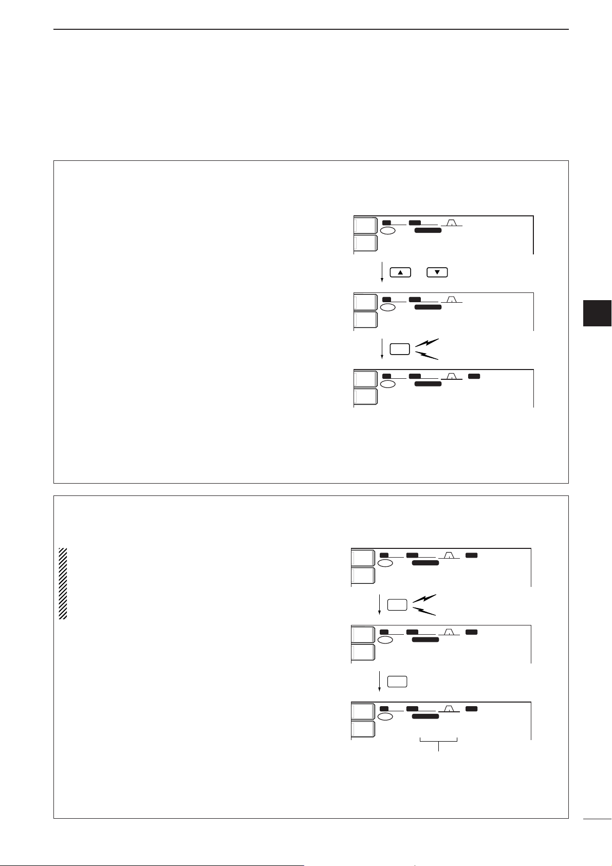
80
8
MEMORY OPERATION
8
■ Frequency transferring
The frequency and operating mode in a memory channel can be transferred to the VFO.
Frequency transferring can be performed in either VFO
mode or memory mode.
•Transferring in VFO mode
This is useful for transferring programmed contents to
VFO.
q Select VFO mode with [VFO/MEMO].
w Select the memory channel to be transferred with
[YY]/[ZZ].
•Memory channel screen is convenient for selecting the
desired channel.
•Memory channel contents appear in the memory channel readout (below the frequency readout).
•“--.---.--” appears if the selected memory channel is a
blank channel. In this case transferring is impossible.
e Push [VFO/MEMO] for 1 sec. to transfer the fre-
quency and operating mode.
•Transferred frequency and operating mode appear on
the frequency readout.
TRANSFERRING EXAMPLE IN VFO MODE
Operating frequency : 21.320 MHz/USB (VFO)
Contents of M-ch 16 : 14.018 MHz/CW
or
Push for 1 sec.
Beep
Beep
Beep
SFTSFT
0
FIL2FIL2
USBUSB
TXTX
USBUSB
wq.ewp.pp
14.950.0014.950.00
1
VFOVFO
BWBW
2.4k2.4k
SFTSFT
0
FIL2FIL2
USBUSB
TXTX
CWCW
wq.ewp.pp
14.018.0014.018.00
1616
VFOVFO
BWBW
2.4k2.4k
SFTSFT
0
FIL2FIL2
CWCW
TXTX
CWCW
qr.pqi.pp
14.018.0014.018.00
1616
VFOVFO
BWBW
500500
BPFBPF
ANT
1
METERMETER
PoPo
ANTANT
1
METERMETER
Po
ANTANT
1
METERMETER
Po
qw:pp
12:00
qw:pp
12:00
qw:pp
12:00
VFO/
MEMO
•Transferring in memory mode
This is useful for transferring frequency and operating mode while operating in memory mode.
When you have changed the frequency or operating mode in the selected memory channel:
• Displayed frequency and mode are transferred.
•Programmed frequency and mode in the mem-
ory channel are not transferred, and they remain
in the memory channel.
q Select the memory channel to be transferred with
[YY]/[ZZ] in memory mode.
•And, set the frequency or operating mode if required.
w Push [VFO/MEMO] for 1 sec. to transfer the fre-
quency and operating mode.
•Displayed frequency and operating mode are transferred to the VFO.
e To return to VFO mode, push [VFO/MEMO] mo-
mentarily.
TRANSFERRING EXAMPLE IN MEMORY MODE
Operating frequency : 14.020 MHz/CW (M-ch 16)
Contents of M-ch 16 : 14.018 MHz/CW
Push for 1 sec.
Programmed contents appear.
Beep
Beep
Beep
VFO/
MEMO
VFO/
MEMO
SFTSFT
0
FIL2FIL2
CWCW
TXTX
USBUSB
qr.pwp.pp
21.320.0021.320.00
VFOVFO
1616
BWBW
500500
SFTSFT
0
FIL2FIL2
CWCW
TXTX
CWCW
qr.pwp.pp
14.018.0014.018.00
1616
VFOVFO
BWBW
500500
SFTSFT
0
FIL2FIL2
CWCW
TXTX
CWCW
qr.pwp.pp
14.020.0014.020.00
VFOVFO
1616
BWBW
500500
BPFBPF
BPFBPF
BPFBPF
ANT
1
METERMETER
Po
ANT
1
METERMETER
Po
ANT
1
METERMETER
Po
qw:pp
12:00
qw:pp
12:00
qw:pp
12:00
Page 86

81
8
MEMORY OPERATION
■ Memory names
All memory channels (including scan edges) can be
tagged with alphanumeric names of up to 10 characters each.
Capital letters, small letters, numerals, some symbols
(! # $ % & ¥ ? " ’ ` ^ + – ✱ / .,: ; = < > ( ) [ ] { } | _ _)
and spaces can be used.
•Editing (programming) memory names
q Push [EXIT/SET] several times to close a multi-
function screen, if necessary.
w Push [(F-4)MEMORY] to select the memory chan-
nel screen.
e Select the desired memory channel.
r Push [(F-4)NAME] to edit memory channel name.
•Acursor appears and blinks.
•Memory channel names of blank channels cannot be
edited.
t Input the desired character by rotating the tuning
dial or by pushing the band key for number input.
•Push [ABC] or [abc] to toggle capital and small letters.
•Push [123] or [etc] to toggle numerals and symbols.
• Push [(F-1)ΩΩ] or [(F-2)≈≈] for cursor movement.
• Push [(F-3)DEL] to delete the selected character.
• Push [(F-4)SPACE] to input a space.
•Pushing the transceiver’s keypad, [0]–[9], can also
enter numerals.
y Push [EXIT/SET] to input and set the name.
• The cursor disappears.
u Repeat steps e to y to program another memory
channel’s name, if desired.
i Push [EXIT/SET] to exit the memory channel
screen.
123123
ABCABC
SFTSFT
0
FIL2FIL2
USBUSB
TXTX
VFOVFO
USBUSB
USBUSB
USBUSB
FIL2FIL2
qr.qot.pp
qr.wpt.pp
14.100.0014.100.00
14.100.0014.100.00
1
1
VFOVFO
BWBW
2.4k2.4k
9999 --.---.----.---.-- ------------ ------
P1P1 0.500.000.500.00 LSBLSB FL2FL2 SCAN EDGESCAN EDGE
P2P2 29.999.9929.999.99 USBUSB FL2FL2 SCAN EDGESCAN EDGE
1 14.100.0014.100.00 USBUSB FL2FL2 _
2 --.---.----.---.-- ------------ ------
3 --.---.----.---.-- ------------ ------
4 --.---.----.---.-- ------------ ------
MEMORYMEMORY
ç
å
DELDEL
SPACESPACE WIDEWIDE
ABCABC
qw:pp
12:00
Character
group
keys
Selected
character
ROLLROLL
SETSET
SELECTSELECT
NAMENAME
WIDEWIDE
SFTSFT
0
FIL2FIL2
USBUSB
TXTX
VFOVFO
USBUSB
USBUSB
USBUSB
FIL2FIL2
qr.qot.pp
qr.wpt.pp
14.100.0014.100.00
14.100.0014.100.00
1
1
VFOVFO
BWBW
2.4k2.4k
9999 --.---.----.---.-- ------------ ------
P1P1 0.500.000.500.00 LSBLSB FL2FL2 SCAN EDGESCAN EDGE
P2P2 29.999.9929.999.99 USBUSB FL2FL2 SCAN EDGESCAN EDGE
1 14.100.0014.100.00 USBUSB FL2FL2
2 --.---.----.---.-- ------------ ------
3 --.---.----.---.-- ------------ ------
4 --.---.----.---.-- ------------ ------
MEMORYMEMORY
ANTANT
1
COMPCOMP
OFFOFF
WIDEWIDE
METERMETER
PoPo
P.AMPP.AMP
1
AGCAGC
MIDMID
ATTATT
OFFOFF
VOXVOX
OFFOFF
qw:pp
12:00
■ Memory clearing
Any unnecessary memory channels can be cleared.
The cleared memory channels become blank channels.
q Select memory mode with [VFO/MEMO].
w Select the desired memory channel with [YY]/[ZZ].
e Push [M-CL] for 1 sec. to clear the contents.
•The programmed frequency and operating mode disappear.
r To clear other memory channels, repeat steps w
and e.
SFTSFT
0
FIL2FIL2
USBUSB
TXTX
wr.oyp.pp
1212
BWBW
2.4k2.4k
SFTSFT
0
TXTX
CWCW
≥qot≥pp
14.195.0014.195.00
VFOVFO
1212
BWBW
2.4k2.4k
CWCW
14.195.0014.195.00
VFOVFO
ANTANT
1
METERMETER
Po
ANTANT
1
METERMETER
Po
qw:pp
12:00
qw:pp
12:00
Push for 1 sec.
M-CL
Beep
Beep
Beep
Page 87

82
8
MEMORY OPERATION
8
■ Memo pads
The transceiver has a memo pad function to store frequency and operating mode for easy write and recall.
The memo pads are separate from memory channels.
The default number of memo pads is 5, however, this
can be increased to 10 in set mode if desired. (p. 102)
Memo pads are convenient when you want to memorize a frequency and operating mode temporarily, such
as when you find a DX station in a pile-up, or when a
desired station is busy for a long time and you want to
temporarily search for other stations.
Use the transceiver’s memo pads instead of relying on
hastily scribbled notes that are easily misplaced.
•Writing frequencies and operating
modes into memo pads
You can simply write the accessed readout frequency
and operating mode by pushing [MP-W].
When you write a 6th frequency and operating mode,
the oldest written frequency and operating mode are
automatically erased to make room for the new settings.
Each memo pad must have its own unique combination of frequency and operating mode; memo
pads having identical settings cannot be written.
Displayed frequency and mode
Push
Newest
The oldest written frequency
and mode are erased.
Oldest
MP-W
wq.wii.ww
USB
wq.wuy.pp
USB
wq.pwr.tw
USB
wq.pqi.py
USB
qr.qiw.rp
USB
qr.qot.pp
USB
MEMO
PADS
•Calling up a frequency from a memo pad
You can simply call up the desired frequency and operating mode of a memo pad by pushing [MP-R] sev-
eral times.
• Both VFO and memory modes can be used.
•The frequency and operating mode are called up, starting
from the most recently written.
When you call up a frequency and an operating mode
from memo pads with [MP-R], the previously displayed frequency and operating mode are automatically stored in a temporary pad. The frequency and
operating mode in the temporary pad can be recalled
by pushing [MP-R] several times.
•You may think there are 6 memo pads because 6 different
frequencies (5 are in memo pads and 1 is in the temporary pad) are called up by [MP-R].
If you change the frequency or operating mode
called up from a memo pad with the tuning dial,
etc., the frequency and operating mode in the temporary pad are erased.
VFO or MEMORY
mode display
MEMO PADS
TEMPORARY PAD
Push
Pushing [MP-R] calls up the
frequency and operating
mode in a memo pad and
the temporary pad sequentially.
Frequency and mode before
pushing [
MP-R].
MP-R
wq.rit.pp
USB
qr.qot.pp
USB
wq.wuy.pp
USB
wq.pwr.tw
USB
wq.pqi.py
USB
qr.qiw.rp
USB
qr.qot.pp
USB
Page 88

■ Scan types
■ Preparation
•Channels
For programmed scan:
Program scan edge frequencies into scan edge memory channels P1 and P2.
For
∂
F scan:
Set the ∂F span (∂F scan range) in the scan screen.
For memory scan:
Program 2 or more memory channels except scan
edge memory channels.
For select memory scan:
Designate 2 or more memory channels as select memory channels. To designate the channel as a select
memory channel, choose a memory channel, then
push [(F-3)SELECT] in the scan screen (memory
mode) or in the memory channel screen.
•Scan resume ON/OFF
You can select the scan to resume or cancel when detecting a signal, in set mode. Scan resume ON/OFF
must be set before operating a scan. See p. 87 for
ON/OFF setting and scan resume condition details.
•Scan speed
Scan speed can be selected from 2 levels, high or low,
in set mode. See p. 87 for details.
•Squelch condition
•The scan function can be used on the main readout only.
•You can operate a scan while operating on a frequency using
the dualwatch or split functions. See p. 63 for details.
SQUELCH
CLOSED
SQUELCH
OPEN
Scan stops when detecting a signal.
If you set scan resume ON in set mode, the
scan pauses for 10 sec. when detecting a
signal, then resumes. When a signal disappears while scan is paused, scan resumes
2 sec. later.
The scan continues
until it is stopped
manually, and does
not pause even if it
detects signals.
Scan pauses on
each channel when
the scan resume is
ON; not applicable
when OFF.
SCAN
PROGRAMMED
STARTS
SCAN
MEMORY SCAN
WITH
9
83
SCANS
PROGRAMMED SCAN
Repeatedly scans between two scan edge frequencies
(scan edge memory channels P1 and P2).
Scan edge
P1 or P2
Scan
Jump
This scan operates in VFO mode.
MEMORY SCAN
Repeatedly scans all programmed memory channels.
ß (select)
Mch 2 Mch 3 Mch 4
Mch 1 Mch 5
ß (select)
Blank channel Blank channel
Scan edge
P2 or P1
ß (select)
∂F SCAN
Repeatedly scans within ∂F span area.
Start frequency
∂F frequency +∂F frequency
–
ScanScan
Jump
This scan operates in both VFO and memory modes.
SELECT MEMORY SCAN
Repeatedly scans all select memory channels.
ß (select)
Mch 2 Mch 3 Mch 4
Mch 1 Mch 5
ß (select)
ß (select)
Mch 6Mch 7Mch 99
ß (select)ß (select)
Mch 6Mch 7Mch 99
ß (select)ß (select)
This scan operates in memory mode.This scan operates in memory mode.
Page 89

84
9
SCANS
9
■ Programmed scan operation
q Push [EXIT/SET] several times to close a multi-
function screen, if necessary.
w Select VFO mode.
e Select the desired operating mode.
•The operating mode can also be changed while scanning.
r Push [(F-5)SCAN] to select the scan screen.
t Set [RF/SQL] open or closed.
• See previous page for scan condition.
•If the [RF/SQL] control function is set as “AUTO,” the
squelch is always open in SSB, CW and RTTY modes.
See pgs. 2, 30, 99 for details.
y Push [(F-1)PROG] to start the programmed scan.
• Decimal points blink while scanning.
u When the scan detects a signal, the scan stops,
pauses or ignores it depending on the resume setting and the squelch condition.
i To cancel the scan, push [(F-1)PROG].
If the same frequencies are programmed into the
scan edge memory channel P1 and P2, programmed scan does not start.
SFT
FIL2
USB
TX
VFO
USB
USB
USB
FIL2
14.100.00
14.100.00
VFO
BW
2.4k
SCAN
COMP
WIDE
METER
P.AMP
AGC
MID
ATT
OFF
VOX
OFF
PROG
FINE
F SPAN
SET
PROGRAM SCAN
Span
±
10kHz
Programmed
P1:
0.500.00MHz
scan
edges
P2:
29.999.99MHz
PROG
FINE
F SPAN
SET
SCAN
COMP
OFF
WIDE
AGC
MID
VOX
OFF
Span
±
10kHz
Programmed
P1:
0.500.00MHz
scan
edges
P2:
29.999.99MHz
■
∂∂
F scan operation
q Push [EXIT/SET] several times to close a multi-
function screen, if necessary.
w Select VFO mode or a memory channel.
e Select the desired operating mode.
•The operating mode can also be changed while scanning.
r Push [(F-5)SCAN] to select the scan screen.
t Set [RF/SQL] open or closed.
• See previous page for scan condition.
•If the [RF/SQL] control function is set as “AUTO,” the
squelch is always open in SSB, CW and RTTY modes.
See pgs. 2, 30, 99 for details.
y Set the ∂F span by pushing [(F-4)∂∂F SPAN].
•±5 kHz, ±10 kHz, ±20 kHz, ±50 kHz, ±100 kHz,
±500 kHz and ±1000 kHz are selectable.
u Set center frequency of the ∂F span.
i Push [(F-2)∂∂F] to start the ∂F scan.
• Decimal points blink while scanning.
o When the scan detects a signal, the scan stops,
pauses or ignores it depending on the resume setting and the squelch condition.
!0 To cancel the scan, push [(F-2)∂∂F].
SFTSFT
0
FIL2FIL2
USBUSB
TXTX
VFOVFO
USBUSB
USBUSB
USBUSB
FIL2FIL2
qr.qot.pp
qr.wpt.pp
14.100.0014.100.00
14.100.0014.100.00
1
1
VFOVFO
BWBW
2.4k2.4k
SCANSCAN
ANT
1
COMPCOMP
OFF
WIDEWIDE
METERMETER
Po
P.AMPP.AMP
1
AGCAGC
MIDMID
ATTATT
OFFOFF
VOXVOX
OFFOFF
PROGPROG
∂
F FINEFINE
∂
F SPANF SPAN
SETSET
qw:pp
12:00
∂ F SCANSCAN
∂ F CenterCenter: 14.195.00MHz14.195.00MHz
∂ F SpanSpan: ±±10kHz10kHz
ProgrammedProgrammed P1:P1:0.500.00MHz0.500.00MHz
scanscan edgesedgesP2:P2: 29.999.99MHz29.999.99MHz
PROGPROG
∂
F FINEFINE
∂
F SPANF SPAN
SETSET
SCANSCAN
COMPCOMP
OFFOFF
WIDEWIDE
AGCAGC
MIDMID
VOXVOX
OFFOFF
∂ F SpanSpan: ±±10kHz10kHz
ProgrammedProgrammed P1:P1:0.500.00MHz0.500.00MHz
scanscan edgesedgesP2:P2: 29.999.99MHz29.999.99MHz
P1:
P2:
SCAN
: ±
10kHz
0.500.00MHz
29.999.99MHz
F SPAN
∂
SET
AGC
MID
VOX
OFF
COMP
OFF
WIDE
PROG
∂ F Span
Programmed
scan
edges
F FINE
∂
ANT
1
METER
Po
P.AMP
1
ATT
OFF
AGC
MID
VOX
OFF
COMP
OFF
WIDE
PROG
2.4k
BW
VFO
TX
qr.qot.pp
1
VFO
SFT
USB
0
USB
14.100.00
FIL2
FIL2
qr.wpt.pp
14.100.00
1
PROGRAM SCAN
∂ F Span
Programmed
scan
edges
F FINE
∂
P1:
P2:
SCAN
: ±
10kHz
0.500.00MHz
29.999.99MHz
∂
USB
USB
F SPAN
qw:pp
12:00
SET
Page 90

85
9
SCANS
■ Fine programmed scan/fine ∂F scan
Fine scan functions as programmed or ∂F scan, but
scan speed decreases when the squelch opens but
does not stop. The scanning tuning step shifts from
50 Hz to 10 Hz while the squelch opens.
q Push [EXIT/SET] several times to close a multi-
function screen, if necessary.
w Push [(F-5)SCAN] to select the scan screen.
e Set for programmed scan or ∂F scan as described
on previous page.
r Push [(F-1)PROG] or [(F-2)∂∂F] to start a scan.
• Decimal points blink while scanning.
t Push [(F-3)FINE] to start a fine scan.
•“FINE PROGRAM SCAN” or “FINE ∂F SCAN” appears.
y When the scan detects a signal, the scan speed
decreases but does not stop.
u Push [(F-1)PROG] or [(F-2)∂∂F] to stop the scan;
push [(F-3)FINE] to cancel the fine scan.
SFTSFT
0
FIL2FIL2
USBUSB
TXTX
VFOVFO
USBUSB
USBUSB
USBUSB
FIL2FIL2
qr.qot.pp
qr.wpt.pp
14.100.0014.100.00
14.100.0014.100.00
1
1
VFOVFO
BWBW
2.4k2.4k
SCANSCAN
ANTANT
1
COMPCOMP
OFFOFF
WIDEWIDE
METERMETER
PoPo
P.AMPP.AMP
1
AGC
MID
ATT
OFF
VOX
OFF
PROGPROG
∂
F FINEFINE
∂
F SPANF SPAN
SETSET
qw:pp
12:00
FINE PROGRAM SCANFINE PROGRAM SCAN
∂ F SpanSpan: ±±10kHz10kHz
ProgrammedProgrammed P1:P1:0.500.00MHz0.500.00MHz
scanscan edgesedgesP2:P2: 29.999.99MHz29.999.99MHz
SFTSFT
0
FIL2FIL2
USBUSB
TXTX
VFOVFO
USBUSB
USBUSB
USBUSB
FIL2FIL2
qr.qot.pp
qr.wpt.pp
14.100.0014.100.00
14.100.0014.100.00
1
1
VFOVFO
BWBW
2.4k2.4k
SCANSCAN
ANTANT
1
COMPCOMP
OFFOFF
WIDEWIDE
METERMETER
PoPo
P.AMPP.AMP
1
AGCAGC
MIDMID
ATTATT
OFFOFF
VOXVOX
OFFOFF
PROGPROG
∂
F FINEFINE
∂
F SPANF SPAN
SETSET
qw:pp
12:00
PROGRAM SCANPROGRAM SCAN
∂ F SpanSpan: ±±10kHz10kHz
ProgrammedProgrammed P1:P1:0.500.00MHz0.500.00MHz
scanscan edgesedgesP2:P2: 29.999.99MHz29.999.99MHz
■ Memory scan operation
q Push [EXIT/SET] several times to close a multi-
function screen, if necessary.
w Select memory mode.
e Push [(F-5)SCAN] to select the scan screen.
r Set [RF/SQL] open or closed.
• See p. 83 for scan condition.
•If the [RF/SQL] control function is set as “AUTO,” the
squelch is always open in SSB, CW and RTTY modes.
See pgs. 2, 30, 99 for details.
t Push [(F-1)MEMO] to start the memory scan.
• Decimal points blink while scanning.
y When the scan detects a signal, the scan stops,
pauses or ignores it depending on the resume setting and the squelch condition.
u To cancel the scan, push [(F-1)MEMO].
2 or more memory channels must be programmed
for memory scan to start.
SFT
FIL2
USB
TX
VFO
USB
USB
USB
FIL2
14.100.00
14.100.00
VFO
12
BW
2.4k
SCAN
ANT
COMP
OFF
WIDE
METER
Po
P.AMP
MEMO
SELECT
F SPAN
SET
MEMORY SCAN
Span
±
10kHz
Programmed
P1:
0.500.00MHz
scan
edges
P2:
29.999.99MHz
SFT
FIL2
USB
TX
VFO
USB
USB
USB
FIL2
14.100.00
14.100.00
VFO
12
BW
2.4k
SCAN
ANT
COMP
OFF
WIDE
METER
Po
P.AMP
AGC
MID
ATT
OFF
VOX
OFF
MEMO
SELECT
F SPAN
SET
Span
±
10kHz
Programmed
P1:
0.500.00MHz
scan
edges
P2:
29.999.99MHz
ANT
METER
P.AMP
ATT
OFF
AGC
MID
VOX
OFF
COMP
OFF
WIDE
2.4k
BW
1
Po
1
12
TX
qr.qot.pp
VFO
VFO
SFT
USB
0
USB
14.100.00
qr.wpt.pp
14.100.00
1
∂ F Span
P1:
P2:
: ±
MEMO
Programmed
scan
edges
F SELECT
∂
FIL2
USB
FIL2
USB
SCAN
10kHz
0.500.00MHz
29.999.99MHz
F SPAN
∂
qw:pp
12:00
SET
ANT
1
METER
Po
P.AMP
1
ATT
OFF
AGC
MID
VOX
OFF
COMP
OFF
WIDE
2.4k
BW
12
TX
qr.qot.pp
VFO
VFO
SFT
USB
0
USB
14.100.00
FIL2
FIL2
qr.wpt.pp
14.100.00
MEMO
1
MEMORY SCAN
∂ F Span
Programmed
scan
edges
F SELECT
∂
P1:
P2:
SCAN
: ±
29.999.99MHz
USB
10kHz
0.500.00MHz
F SPAN
∂
USB
qw:pp
12:00
SET
Page 91

86
9
SCANS
9
■ Select memory scan operation
q Push [EXIT/SET] several times to close a multi-
function screen, if necessary.
w Select memory mode.
e Push [(F-5)SCAN] to select the scan screen.
r Set [RF/SQL] open or closed.
• See p. 83 for scan condition.
•If the [RF/SQL] control function is set as “AUTO,” the
squelch is always open in SSB, CW and RTTY modes.
See pgs. 2, 30, 99 for details.
t Push [(F-1)MEMO] to start the memory scan.
• Decimal points blink while scanning.
y Push [(F-3)SELECT] to start select memory scan;
push [(F-3)SELECT] again to return to memory
scan, if desired.
u When the scan detects a signal, the scan stops,
pauses or ignores it depending on the resume setting and the squelch condition.
i To cancel the scan, push [(F-1)MEMO].
2 or more memory channels must be designated
as select memory channels for select memory
scan to start.
SFT
FIL2
USB
TX
VFO
USB
USB
USB
FIL2
14.100.00
14.100.00
VFO
BW
2.4k
SCAN
COMP
WIDE
METER
P.AMP
AGC
MID
ATT
OFF
VOX
OFF
MEMO
SELECT
F SPAN
SET
SELECT MEMORY SCAN
Span
±
10kHz
Programmed
P1:
0.500.00MHz
scan
edges
P2:
29.999.99MHz
SFT
FIL2
USB
TX
VFO
USB
USB
USB
FIL2
14.100.00
14.100.00
VFO
12
BW
2.4k
SCAN
ANT
COMP
OFF
WIDE
METER
Po
P.AMP
AGC
MID
ATT
OFF
VOX
OFF
MEMO
SELECT
F SPAN
SET
Span
±
10kHz
Programmed
P1:
0.500.00MHz
scan
edges
P2:
29.999.99MHz
■ Setting select memory channels
q Push [EXIT/SET] several times to close a multi-
function screen, if necessary.
w Select memory mode.
e Push [(F-5)SCAN] to select the scan screen.
r Select the desired memory channel to set as a se-
lect memory channel.
t Push [(F-3)SELECT] to set the memory channel
as a select memory or not.
y Repeat steps r to t to program another memory
channel as a select memory channel, if desired.
u Push [EXIT/SET] to exit the scan screen.
Select memory channels can also be set in the
memory channel screen. (p. 78)
SFT
FIL2
USB
TX
VFO
USB
USB
USB
FIL2
14.100.00
14.100.00
VFO
BW
2.4k
SCAN
COMP
WIDE
METER
P.AMP
AGC
MID
ATT
OFF
VOX
OFF
MEMO
SELECT
F SPAN
SET
Span
±
10kHz
Programmed
P1:
0.500.00MHz
scan
edges
P2:
29.999.99MHz
SFT
FIL2
USB
TX
VFO
USB
USB
USB
FIL2
14.100.00
14.100.00
VFO
12
BW
2.4k
SCAN
ANT
COMP
OFF
WIDE
METER
Po
P.AMP
AGC
MID
ATT
OFF
VOX
OFF
MEMO
SELECT
F SPAN
SET
Span
±
10kHz
Programmed
P1:
0.500.00MHz
scan
edges
P2:
29.999.99MHz
ANT
1
METER
Po
P.AMP
1
ATT
OFF
AGC
MID
VOX
OFF
COMP
OFF
WIDE
MEMO
2.4k
BW
12
TX
qr.qot.pp
VFO
VFO
∂ F Span
Programmed
scan
0
SFT
USB
FIL2
14.100.00
USB
qr.wpt.pp
14.100.00
1
P1:
edges
P2:
F SELECT
∂
USB
FIL2
USB
SCAN
: ±
10kHz
0.500.00MHz
29.999.99MHz
F SPAN
∂
qw:pp
12:00
SET
ANT
1
METER
Po
P.AMP
1
ATT
OFF
AGC
MID
VOX
OFF
COMP
OFF
WIDE
MEMO
2.4k
BW
1212ß
TX
qr.qot.pp
VFO
VFO
SELECT MEMORY SCAN
∂ F Span
Programmed
scan
0
SFT
USB
FIL2
14.100.00
USB
qr.wpt.pp
14.100.00
1
P1:
edges
P2:
F SELECT
∂
USB
FIL2
USB
SCAN
: ±
10kHz
0.500.00MHz
29.999.99MHz
F SPAN
∂
qw:pp
12:00
SET
ANT
1
METER
Po
P.AMP
1
ATT
OFF
AGC
MID
VOX
OFF
COMP
OFF
WIDE
MEMO
2.4k
BW
12
TX
qr.qot.pp
VFO
VFO
∂ F Span
Programmed
scan
0
SFT
USB
FIL2
14.100.00
USB
qr.wpt.pp
14.100.00
1
P1:
edges
P2:
F SELECT
∂
USB
FIL2
USB
SCAN
: ±
10kHz
0.500.00MHz
29.999.99MHz
F SPAN
∂
qw:pp
12:00
SET
“ß” appears for select memory channels.
ANT
1
METER
Po
P.AMP
1
ATT
OFF
AGC
MID
VOX
OFF
COMP
OFF
WIDE
MEMO
2.4k
BW
1212ß
TX
qr.qot.pp
VFO
VFO
∂ F Span
Programmed
scan
0
SFT
USB
FIL2
14.100.00
USB
qr.wpt.pp
14.100.00
1
P1:
edges
P2:
F SELECT
∂
USB
FIL2
USB
SCAN
: ±
10kHz
0.500.00MHz
29.999.99MHz
F SPAN
∂
qw:pp
12:00
SET
Page 92

87
9
SCANS
■ Scan set mode
Scan set mode is used for programming scanning
speed and scan resume condition.
•Scan speed
The transceiver has 2 speeds for scanning, high and
low.
q Push [EXIT/SET] several times to close a multi-
function screen, if necessary.
w Push [(F-5)SCAN] to select the scan screen.
e Push [(F-5)SET] to select the scan set mode
screen.
r Push [(F-1)YY] to select the scan speed item.
t Rotate the tuning dial to select the scan speed.
•Push [(F-3)DEF] to select the default condition.
y Push [EXIT/SET] to exit the scan set mode.
•Scan resume condition
This item sets the scan resume function ON or OFF.
ON: scan resumes 10 sec. after stopping on a signal
(or 1 sec. after a signal disappears); OFF: scan does
not resume after stopping on a signal.
q Push [EXIT/SET] several times to close a multi-
function screen, if necessary.
w Push [(F-5)SCAN] to select the scan screen.
e Push [(F-5)SET] to select the scan set mode
screen.
r Push [(F-2)ZZ] to select the scan resume condition
item.
t Rotate the tuning dial to turn the scan resume
function ON or OFF.
•Push [(F-3)DEF] to select the default condition.
y Push [EXIT/SET] to exit the scan set mode.
é
è
DEF
SCAN SET
COMPCOMP
OFFOFF
WIDEWIDE
AGC
MID
VOX
OFF
SCAN SpeedSCAN Speed HIGHHIGH
SCAN ResumeSCAN Resume ONON
é
è
DEF
SCAN SET
COMPCOMP
OFFOFF
WIDEWIDE
AGCAGC
MIDMID
VOXVOX
OFFOFF
SCAN SpeedSCAN Speed HIGHHIGH
SCAN ResumeSCAN Resume ONON
PROGPROG
∂
F FINEFINE
∂
F SPANF SPAN
SETSET
SCANSCAN
COMPCOMP
OFFOFF
WIDEWIDE
AGCAGC
MIDMID
VOXVOX
OFFOFF
∂ F SpanSpan: ±±10kHz10kHz
ProgrammedProgrammed P1:P1:0.500.00MHz0.500.00MHz
scanscan edgesedgesP2:P2: 29.999.99MHz29.999.99MHz
■ Tone scan
The transceiver can detect the subaudible tone frequency in a received signal. By monitoring a signal
that is being transmitted on a repeater input frequency, you can determine the tone frequency required to access the repeater.
q Set the desired frequency or memory channel to
be checked for a tone frequency.
w Push [AM/FM] several times to select FM mode.
e Push [TONE] for 1 sec. to enter the tone fre-
quency screen.
r Push [(F-1)YY] or [(F-2)ZZ] to check the repeater
tone frequency or tone squelch frequency, respectively. (pgs. 52, 53)
t Push [(F-5)T-SCAN] to start the tone scan.
• “SCAN” flashes while scanning.
y When the tone frequency is detected, the tone
scan pauses.
•The tone frequency is set temporarily on a memory
channel. Program into the memory channel to store the
tone frequency permanently.
•The decoded tone frequency is used for the repeater
tone frequency or tone squelch frequency.
u To stop the scan, push [(F-5)T-SCAN].
i Push [EXIT/SET] to exit the tone frequency
screen.
TONE FREQUENCYTONE FREQUENCY
188.8Hz188.8Hz SCANSCAN
88.5Hz88.5HzT-SQL TONET-SQL TONE
REPEATER TONEREPEATER TONE
TONETONE
AGC
FASTFAST
VOX
OFF
T-SCANT-SCAN
T-SCANT-SCAN
é
è
DEFDEF
TONE FREQUENCYTONE FREQUENCY
88.5Hz88.5Hz
88.5Hz88.5HzT-SQL TONET-SQL TONE
REPEATER TONEREPEATER TONE
AGCAGC
FASTFAST
VOXVOX
OFFOFF
TONETONE
OFFOFF
Page 93

10
88
ANTENNA TUNER OPERATION
■ Automatic antenna selection
The transceiver covers 0.1–60 MHz over 10 bands.
Each band key has a band memory which can memorize a selected antenna (ANT1, ANT2, ANT1/RX antenna and ANT2/RX antenna). When you change the
operating frequency beyond a band, the previously
used antenna is automatically selected for the new
band. This function is convenient when you use 2 or 3
antennas.
To use the band memory, enter set mode and confirm
that “Auto” is selected as the [ANT] switch item.
(p. 101)
•When OFF is selected, the [ANT] switch does not function
and [ANT1] is always selected.
•When “Manual” is selected, the [ANT] switch functions,
however, band memory does not function. In this case, you
must select an antenna manually.
•When “Auto” is selected (default setting), the antenna tuner
ON/OFF condition is also memorized in the band memory.
•When “Auto” or “Manual” is selected, the antenna tuner
ON/OFF condition is consistent with the [ANT] switch.
•Antenna switch selection example
Under the following condition, “Auto” should be selected as the [ANT] switch set mode item.
- When you use 2 antennas.
Under the following conditions, “Manual” should be selected as the [ANT] switch set mode item.
- When using 1 antenna.
- When using an external antenna selector for more
than 3 antennas (except for receive antenna).
- When using an external antenna tuner.
[ANT]
DEFDEF WIDEWIDE
é
è
VOXVOX
OFFOFF
COMPCOMP
OFFOFF
WIDEWIDE
AGCAGC
MIDMID
FMFM SPLITSPLIT Offset(HF)Offset(HF) -0.100MHz-0.100MHz
FMFM SPLITSPLIT Offset(50M)Offset(50M) -0.500MHz-0.500MHz
SPLITSPLIT LOCKLOCK OFFOFF
TunerTuner (Auto(Auto Start)Start) OFFOFF
TunerTuner (PTT(PTT Start)Start) OFFOFF
[ANT][ANT] SwitchSwitch AutoAuto
RTTYRTTY Mark FrequencyMark Frequency 21252125
OTHERSOTHERSSETSET
10
Page 94

■ Antenna tuner operation
The internal automatic antenna tuner matches the
transceiver to the connected antenna automatically.
Once the tuner matches an antenna, the variable capacitor angles are memorized as a preset point for
each frequency range (100 kHz steps). Therefore,
when you change the frequency range, the variable
capacitors are automatically preset to the memorized
point.
CAUTION: NEVER transmit with the tuner ON
when no antenna is connected. This will damage
the transceiver. Be careful of the antenna selection.
TUNER OPERATION
➥ Push the [TUNER] switch to turn the internal an-
tenna tuner ON. The antenna is tuned automatically when the antenna SWR is higher than 1.5:1.
• When the tuner is ON, the [TUNER] switch lights.
[TUNER]
MANUAL TUNING
During SSB operation at low voice levels, the internal
tuner may not be tuned correctly. In such cases, manual tuning is helpful.
➥ Push [TUNER] for 1 sec., to start manual tuning.
•Aside tone is emitted and [TUNER] blinks while tuning.
•If the tuner cannot reduce the SWR to less than 1.5:1
after 20 sec. of tuning, the [TUNER] switch indicator
goes out.
Push [TUNER] for 1 sec.
AUTOMATIC TUNER START (HF bands only)
If you want to deactivate the tuner under conditions
of VSWR 1.5:1 or less, use the auto tuner start function and turn the tuner OFF. This function activates
the tuner automatically when the SWR exceeds 1.5:1.
This function is turned ON in set mode. (p. 101).
PTT TUNER START
The tuner is always tuned when the PTT is pushed
after the frequency is changed (more than 1% from
last-tuned frequency). This function removes the
“push and hold [TUNER]” operation and activates for
the first transmission on a new frequency.
This function is turned ON in set mode. (p. 101).
NOTES:
•If the tuner cannot tune the antenna
Check the following and try again:
• the [ANT] connector selection.
• the antenna connection and feedline.
•the unaltered antenna SWR. (Less than 3:1 for HF bands;
Less than 2.5:1 for 50 MHz band)
•the transmit power. (8 W for HF bands; 15 W for 50 MHz
band)
• the power source voltage/capacity.
If the tuner cannot reduce the SWR to less than 1.5:1
after checking the above, perform the following:
• repeat manual tuning several times.
• tune with a 50 Ω dummy load and re-tune the antenna.
• turn power OFF and ON.
•adjust the antenna cable length.
(This is effective for higher frequencies in some cases.)
•Tuning a narrow bandwidth antenna
Some antennas, especially for low bands, have a narrow bandwidth. These antennas may not be tuned at
the edge of their bandwidth, therefore, tune such an
antenna as follows:
Suppose you have an antenna which has an SWR of
1.5:1 at 3.55 MHz and an SWR of 3:1 at 3.8 MHz.
q Push [TUNER] to turn the antenna tuner ON.
w Select CW mode.
e Turn OFF the break-in function. (pgs. 4, 66)
r Push [TRANSMIT] to set to the transmit condition.
t Set 3.55 MHz and key down.
y Set 3.80 MHz and key down.
u Push [TRANSMIT] to return to the receive condition.
89
10
ANTENNA TUNER OPERATION
Page 95

90
10
ANTENNA TUNER OPERATION
10
■ Optional external tuner operation
•AH-4/AH-3 HF AUTOMATIC ANTENNA
TUNER
The AH-4 matches the IC-756PROIII to a long wire
antenna more than 7 m/23 ft long (3.5 MHz and above).
The AH-3 matches the IC-756PROIII to a long wire
antenna more than 3 m/10 ft long
(3.5 MHz and above)
or more than 12 m/40 ft long
(1.8 MHz and above).
• See p. 18 for the transceiver and AH-4/AH-3 connection.
•See the AH-4/AH-3 instruction manual for AH-4/AH-3 in-
stallation and antenna connection details.
AH-4/AH-3 setting example:
RDANGER: HIGH VOLTAGE!
NEVER touch the antenna element while tuning
or transmitting.
NEVER operate the AH-4/AH-3 without an antenna
wire. The tuner and transceiver will be damaged.
NEVER operate the AH-4/AH-3 when it is not
grounded.
Transmitting before tuning may damage the transceiver. Note that the AH-4/AH-3 cannot tune when
using a
1
⁄2λ long wire or multiple of the operating fre-
quency.
•When connecting the AH-4/AH-3, the antenna
connector assignments are [ANT2] for the internal tuner and [ANT1] for the AH-4/AH-3. The antenna indicator in the LCD displays “ANT1(EXT)”
when the AH-4/AH-3 is connected and selected.
•The AH-3 can be used for HF bands only. It cannot be used for the 50 MHz band.
•AH-4/AH-3 operation
Tuning is required for each frequency. Be sure to
re-tune the antenna before transmitting when you
change the frequency—even slightly.
q Set the desired frequency in an HF or 50 MHz
band for use with the AH-4. Set the desired frequency in an HF band for use with the AH-3.
•The AH-4/AH-3 will not operate on frequencies outside
of ham bands.
w Push [TUNER] for 1 sec.
• The [TUNER] light blinks while tuning.
e The [TUNER] light lights constantly when tuning is
complete.
•When the connected wire cannot be tuned, the
[TUNER] light goes out and the AH-4/AH-3 is bypassed. At that point the antenna wire connection is to
the transceiver directly, and not via the AH-4/AH-3 antenna tuner.
r
To bypass the AH-4/AH-3 manually, push
[TUNER].
[TUNER]
•ANTENNA TUNER OF THE IC-PW1
When using an external antenna tuner such as the
IC-PW1’s tuner, tune with the external antenna tuner,
while the internal tuner is turned OFF. After tuning is
completed, turn the internal tuner ON. Otherwise,
both tuners tune simultaneously and correct tuning
may not be obtained.
See the instruction manual included with each antenna tuner for their respective operations.
For mobile operation
For outdoor operation
Long wire
IC-756PROIII
Optional AH-2b
antenna element
Page 96

CCLLOOCCKK22 OOffffsseett
This item sets the desired off-set time period for the
clock 2 indication within –24:00 to +24:00 in 5 min.
steps.
•Push [(F-3)DEF] for 1 sec. to set the default value.
00::0000
(default)
++ 99::0000
Rotate the tuning dial to set
the time.
■ Time set mode
The transceiver has a built-in 24-hour clock with
power-off and power-on timer functions. This is useful
when logging QSO’s and so on. The clock indication is
always displayed except after pushing [(F-INP)ENT].
q Push [EXIT/SET] several times to close a multi-
function screen, if necessary.
w Push [EXIT/SET] for 1 sec. to select the set mode
menu screen.
e Push [(F-4)TIME] to enter the time set mode.
r Push [(F-1)YY] or [(F-2)ZZ] to select the desired
item.
t Rotate the tuning dial to set or select the desired
value or condition.
y Push [EXIT/SET] twice to exit the time set mode.
[(F-4)SET][(F-2)Z] [EXIT/SET][(F-1)Y]
TTiimmee ((NNooww))
This item sets the current time for the built-in 24-hour
clock.
1155::0000
Push [(F-4)SET] to enter the time.
TTiimmeerr FFuunnccttiioonn
This item sets the timer functions ON and OFF.
When the power-ON timer or the power-OFF timer is
used, “ON” must be selected in this item.
•Push [(F-3)DEF] for 1 sec. to set the default value.
OONN
The timer functions can be
operated. (default)
OOFFFF
The timer functions cannot
be operated.
CCLLOOCCKK22 FFuunnccttiioonn
This item turns the clock 2 indication ON and OFF.
The clock 2 is convenient to indicate the UTC or other
country’s local time, etc.
•Push [(F-3)DEF] for 1 sec. to set the default value.
OONN
The clock 2 is displayed
below the local time.
(default)
OOFFFF
The clock 2 does not display.
PPoowweerr--OOFFFF ppeerriioodd
This item sets the power-off period for automatic shutdown after the power-on timer has turned power ON.
6600mmiinn
Push [(F-4)SET] to enter the time.
PPoowweerr--OONN TTiimmeerr sseett
This item sets the power-on time.
1155::0000
Push [(F-4)SET] to enter the time.
11
91
CLOCK AND TIMERS
Page 97
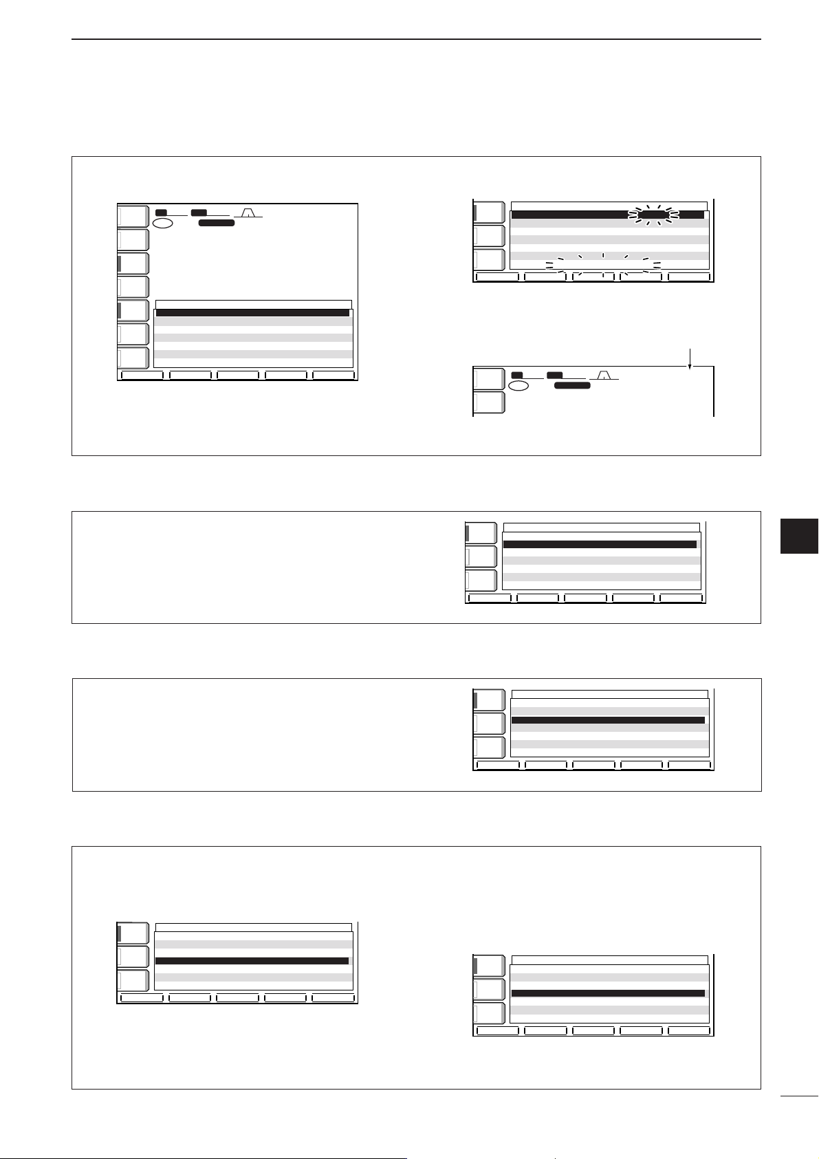
92
11
CLOCK AND TIMERS
DSetting the current time
DClock2 function activity
DClock2 offset setting
DTimer function activity
q Entering time set mode, push [(F-1)YY] to select
the Time (Now) item.
w Set the current time using the tuning dial.
• “TIME–set Push [SET]” blinks.
e Push [(F-4)SET] to enter the set time.
• Push [EXIT/SET] to cancel the setting.
r Push [EXIT/SET] twice to exit time set mode.
SFTSFT
0
FIL2FIL2
USBUSB
TXTX
USBUSB
qr.qot.pp
14.100.0014.100.00
1
VFOVFO
BWBW
2.4k2.4k
ANTANT
1
METERMETER
Po
qt:wr
15:24
Set time appears.
TIME SETTIME SET
é
è
TimeTime (Now)(Now) 15:2415:24
CLOCK2CLOCK2FunctionFunction ONON
CLOCK2CLOCK2OffsetOffset 0:000:00
TimerTimer FunctionFunction ONON
Power-ONPower-ONTimerTimer SetSet 0:000:00
Power-OFFPower-OFFPeriodPeriod 60min60min
TIME-setTIME-setPushPush[SET][SET]
SETSET
COMPCOMP
OFFOFF
WIDEWIDE
AGCAGC
MIDMID
VOXVOX
OFFOFF
SFTSFT
0
FIL2FIL2
USBUSB
TXTX
VFOVFO
USBUSB
USBUSB
USBUSB
FIL2FIL2
qr.qot.pp
qr.wpt.pp
14.100.0014.100.00
14.100.0014.100.00
1
1
VFOVFO
BWBW
2.4k2.4k
TIME SETTIME SET
é
è
TimeTime (Now)(Now) 12:0012:00
CLOCK2CLOCK2FunctionFunction ONON
CLOCK2CLOCK2OffsetOffset 0:000:00
TimerTimer FunctionFunction ONON
Power-ONPower-ONTimerTimer SetSet 0:000:00
Power-OFFPower-OFFPeriodPeriod 60min60min
ANTANT
1
COMPCOMP
OFFOFF
WIDEWIDE
METERMETER
PoPo
P.AMPP.AMP
1
AGCAGC
MIDMID
ATTATT
OFFOFF
VOXVOX
OFFOFF
qw:pp
12:00
q Entering time set mode, push [(F-1)YY] or [(F-2)ZZ]
to select the CLOCK2 Function item.
w Select the timer function activity using the tuning
dial.
e Push [EXIT/SET] twice to exit time set mode.
TIME SETTIME SET
é
è
TimeTime (Now)(Now) 15:2415:24
CLOCK2CLOCK2FunctionFunction ONON
CLOCK2CLOCK2OffsetOffset 0:000:00
TimerTimer FunctionFunction ONON
Power-ONPower-ONTimerTimer SetSet 0:000:00
Power-OFFPower-OFFPeriodPeriod 60min60min
COMPCOMP
OFF
WIDEWIDE
AGCAGC
MIDMID
VOXVOX
OFFOFF
DEF
q Entering time set mode, push [(F-1)YY] or [(F-2)ZZ]
to select the CLOCK2 Offset item.
w Rotate the tuning dial to set the offset time within
–24:00 to +24:00 in 5min. steps.
e Push [EXIT/SET] twice to exit time set mode.
TIME SETTIME SET
é
è
TimeTime (Now)(Now) 15:2415:24
CLOCK2CLOCK2FunctionFunction ONON
CLOCK2CLOCK2OffsetOffset 0:000:00
TimerTimer FunctionFunction ONON
Power-ONPower-ONTimerTimer SetSet 0:000:00
Power-OFFPower-OFFPeriodPeriod 60min60min
COMPCOMP
OFFOFF
WIDEWIDE
AGCAGC
MIDMID
VOXVOX
OFFOFF
DEF
The timer functions can be switched ON and OFF
q Entering time set mode, push [(F-1)YY] or [(F-2)ZZ]
to select the Timer Function item.
w Select the timer function activity using the tuning
dial.
ON : Activates the timer functions when [POWER]
is pushed momentarily. (default)
OFF : Deactivates the timer functions even when
[POWER] is pushed momentarily.
e Push [EXIT/SET] twice to exit time set mode.
TIME SETTIME SET
é
è
TimeTime (Now)(Now) 15:2415:24
CLOCK2CLOCK2FunctionFunction ONON
CLOCK2CLOCK2OffsetOffset 0:000:00
TimerTimer FunctionFunction OFFOFF
Power-ONPower-ONTimerTimer SetSet 19:3019:30
Power-OFFPower-OFFPeriodPeriod 60min60min
COMPCOMP
OFFOFF
WIDEWIDE
AGCAGC
MIDMID
VOXVOX
OFFOFF
DEF
TIME SETTIME SET
é
è
TimeTime (Now)(Now) 15:2415:24
CLOCK2CLOCK2FunctionFunction ONON
CLOCK2CLOCK2OffsetOffset 0:000:00
TimerTimer FunctionFunction ONON
Power-ONPower-ONTimerTimer SetSet 0:000:00
Power-OFFPower-OFFPeriodPeriod 60min60min
COMPCOMP
OFFOFF
WIDEWIDE
AGCAGC
MIDMID
VOXVOX
OFFOFF
DEF
11
Page 98

93
11
CLOCK AND TIMERS
The transceiver can be set to turn OFF automatically
after being activated via the power-on timer. The
power-off period can be set to 5–120 min. in 5 min.
steps.
q Entering time set mode, push [(F-2)ZZ] to select
the Power-OFF Period item.
w Set the desired power-off time using the tuning
dial.
• “TIMER – set Push [SET]” blinks.
e Push [(F-4)SET] to enter the set time.
• Push [EXIT/SET] to cancel the setting.
r Push [EXIT/SET] twice to exit timer set mode.
TIME SETTIME SET
é
è
SETSET
TimeTime (Now)(Now) 15:2415:24
CLOCK2CLOCK2FunctionFunction ONON
CLOCK2CLOCK2OffsetOffset 0:000:00
TimerTimer FunctionFunction ONON
Power-ONPower-ONTimerTimer SetSet 19:3019:30
Power-OFFPower-OFFPeriodPeriod 45min45min
TIMER-setTIMER-setPushPush[SET][SET]
COMPCOMP
OFFOFF
WIDEWIDE
AGCAGC
MIDMID
VOXVOX
OFFOFF
TIME SETTIME SET
é
è
TimeTime (Now)(Now) 15:2415:24
CLOCK2CLOCK2FunctionFunction ONON
CLOCK2CLOCK2OffsetOffset 0:000:00
TimerTimer FunctionFunction ONON
Power-ONPower-ONTimerTimer SetSet 19:3019:30
Power-OFFPower-OFFPeriodPeriod 60min60min
COMPCOMP
OFFOFF
WIDEWIDE
AGCAGC
MIDMID
VOXVOX
OFFOFF
q Preset the power-on time and power-off period as
described previously.
w Push [POWER] momentarily to turn the timer func-
tion ON.
•The [POWER] light lights when the timer function is
ON.
e Push [POWER] for 1 sec. to turn the power OFF.
• The [POWER] light lights continuously.
r When the set time arrives, the power is automati-
cally turned ON.
t The transceiver emits 10 beeps and turns OFF
after the power-off period elapses.
• The [POWER] light blinks while beeping.
•Push [POWER] momentarily to cancel the power-off
timer, if desired.
The timer function in time set mode must be turned
ON to enable the timer operation. See above for
details.
[POWER]
The transceiver can be set to turn ON automatically at
a specified time.
q Entering time set mode, push [(F-1)YY] or [(F-2)ZZ]
to select the Power-ON Time Set item.
w Set the desired power-on time using the tuning
dial.
• “TIMER–set Push [SET]” blinks.
e Push [(F-4)SET] to enter the set time.
• Push [EXIT/SET] to cancel the setting.
r Push [EXIT/SET] twice to exit time set mode.
TIME SETTIME SET
é
è
TimeTime (Now)(Now) 15:2415:24
CLOCK2CLOCK2FunctionFunction ONON
CLOCK2CLOCK2OffsetOffset 0:000:00
TimerTimer FunctionFunction ONON
Power-ONPower-ONTimerTimer SetSet 19:3019:30
Power-OFFPower-OFFPeriodPeriod 60min60min
TIMER-setTIMER-setPushPush[SET][SET]
SETSET
COMPCOMP
OFFOFF
WIDEWIDE
AGCAGC
MIDMID
VOXVOX
OFFOFF
TIME SETTIME SET
é
è
TimeTime (Now)(Now) 15:2415:24
CLOCK2CLOCK2FunctionFunction ONON
CLOCK2CLOCK2OffsetOffset 0:000:00
TimerTimer FunctionFunction ONON
Power-ONPower-ONTimerTimer SetSet 0:000:00
Power-OFFPower-OFFPeriodPeriod 60min60min
COMPCOMP
OFFOFF
WIDEWIDE
AGCAGC
MIDMID
VOXVOX
OFFOFF
DSetting power-on time
DSetting power-off period
DTimer operation
Page 99

12
94
SET MODE
■ Set mode description
Set mode is used for programming infrequently
changed values or conditions of functions. This transceiver has a level set mode, display set mode, timer
set mode and miscellaneous (others) set mode.
•Set mode operation
q Push [EXIT/SET] several times to close a multi-
function screen, if necessary.
w Push [EXIT/SET] for 1 sec. to select the set mode
menu screen.
e Push [(F-1)LEVEL], [(F-2)DISP], [(F-3)DSP], [(F-
4)TIME] or [(F-5)OTHERS] to enter the desired set
mode.
r For level, display or miscellaneous (others) set
mode, push [(F-5)WIDE] to toggle wide and normal
screen.
t Push [(F-1)YY] or [(F-2)ZZ] to select the desired
item.
y Set the desired condition using the tuning dial.
•Push [(F-3)DEF] for 1 sec. to select a default condition
or value.
u Push [EXIT/SET] twice to exit the set mode.
[(F-3)][(F-1)] [EXIT/SET] Tuning dial
[(F-2)] [(F-4)] [(F-5)]
• Display set mode (p. 97)
• Level set mode (p. 95)
• Start up screen
• Set mode menu screen
• DSP set mode (p. 99)
• Time set mode (p. 91)
• Miscellaneous (others) set mode (p. 99)
SFTSFT
0
FIL2FIL2
CWCW
TXTX
VFOVFO
USBUSB
USBUSB
USBUSB
FIL2FIL2
qr.qot.pp
qr.wpt.pp
14.100.0014.100.00
14.100.0014.100.00
1
1
VFOVFO
BWBW
2.4k2.4k
USBUSB
14.100.0014.100.00
1
SET MODESET MODE
LEVEL LEVEL
SETSET
SSB Tx Tone (Bass)SSB Tx Tone (Bass) 0
SSB Tx Tone (Treble)SSB Tx Tone (Treble) 0
SSB TBW (WIDE)SSB TBW (WIDE) L 100100
SSB TBW (WIDE)SSB TBW (WIDE) H 29002900
SSB TBW (MID)SSB TBW (MID) L 300300
SSB TBW (MID)SSB TBW (MID) H 27002700
SSB TBW (NAR)SSB TBW (NAR) L 500500
OTHERS OTHERS
SETSET
TIME TIME
SETSET
DISPLAY DISPLAY
SETSET
SCOPESCOPE
VOICEVOICE KEYERKEYER
MEMORYMEMORY
SCANSCAN
LEVELLEVEL
DISPDISP DSPDSP
TIMETIME
OTHERSOTHERS
é
è
DEFDEF
é
è
DEFDEF
WIDEWIDE
é
è
DEFDEF
WIDEWIDE
SSB-FILSSB-FIL
CW-FILCW-FIL
é
è
DSP FILTER SETDSP FILTER SET
SHARPSHARPSSBSSB
SHARPCW
METERMETER
PoPo
P.AMPP.AMP
1
ATTATT
0FF0FF
BK-INBK-IN
OFFOFF
1/41/4
OFFOFF
AGCAGC
MIDMID
ANTANT
1
EXIT/SET
Push
for 1 sec.
SFTSFT
0
FIL2FIL2
CWCW
TXTX
VFOVFO
USBUSB
USBUSB
FIL2FIL2
qr.qot.pp
qr.wpt.pp
14.100.0014.100.00
1
VFOVFO
BWBW
2.4k2.4k
METERMETER
PoPo
P.AMPP.AMP
1
ATTATT
0FF0FF
BK-INBK-IN
OFFOFF
1/41/4
OFFOFF
AGCAGC
MIDMID
ANTANT
1
BK-INBK-IN
OFFOFF
1/41/4
OFFOFF
AGCAGC
MIDMID
BK-INBK-IN
OFFOFF
1/41/4
OFFOFF
AGCAGC
MIDMID
BK-INBK-IN
OFFOFF
1/41/4
OFFOFF
AGCAGC
MIDMID
BK-INBK-IN
OFFOFF
1/41/4
OFFOFF
AGCAGC
MIDMID
BK-INBK-IN
OFFOFF
1/41/4
OFFOFF
AGCAGC
MIDMID
F-1
F-2
F-3
F-4
F5
qw:pp
12:0012:00
qw:pp
12:0012:00
SET MODE MENUSET MODE MENU
LEVEL LEVEL TX Tone,Monitor,Side Tone etcTX Tone,Monitor,Side Tone etc
DISP Bright,Contrast,Style,Font etc DISP Bright,Contrast,Style,Font etc
DSP DSP DSP Filter TypeDSP Filter Type
TIME Clock/Timer TIME Clock/Timer
OTHERS OTHERS Other Set ModeOther Set Mode
CalibrationCalibrationMarkerMarker OFFOFF
Beep(Confirmation)Beep(Confirmation) ONON
Beep(BandBeep(BandEdge)Edge) ONON
RF/SQLRF/SQLControlControl RF+SQLRF+SQL
QuickQuick DualwatchDualwatch ONON
QuickQuick SPRITSPRIT ONON
FMFM SPLITSPLIT Offset(HF)Offset(HF) -0.100MHz-0.100MHz
TimeTime (Now)(Now) 12:0012:00
CLOCK2 FunctionCLOCK2 Function ONON
CLOCK2 OffsetCLOCK2 Offset 0:000:00
Timer FunctionTimer Function ONON
Power-ONPower-ONTimerTimer SetSet 0:000:00
Power-OFFPower-OFFPeriodPeriod 60min60min
Contrast(LCD) 60%
Bright(LCD) 50%
Horizon 4
Backlight(Switches) 8
DisplayType A
DisplayFont Basic1
MemoryName ON
12
Page 100

95
12
SET MODE
■ Level set mode
SSSSBB TTxx TToonnee ((BBaassss))
This item adjusts the bass level of the transmit audio
tone in SSB mode from –5 dB to +5 dB in 1 dB steps.
0dB
0 dB (default)
SSSSBB TTxx TToonnee ((TTrreebbllee))
This item adjusts the treble level of the transmit audio
tone in SSB mode from –5 dB to +5 dB in 1 dB steps.
0dB
0 dB (default)
SSSSBB TTBBWW ((WWIIDDEE)) LL
These items set the transmission passband width for
wide setting by selecting the lower and higher frequencies.
Lower freq. : 100 (default), 300 and 500 Hz
100
100 Hz (default)
SSSSBB TTBBWW ((WWIIDDEE)) HH
These items set the transmission passband width for
wide setting by selecting the lower and higher frequencies.
Higher freq.: 2500, 2700 and 2900 Hz (default)
2900
2900 Hz (default)
SSSSBB TTBBWW ((MMIIDD)) LL
These items set the transmission passband width for
middle setting by selecting the lower and higher frequencies.
Lower freq. : 100, 300 (default) and 500 Hz
300
300 Hz (default)
SSSSBB TTBBWW ((MMIIDD)) HH
These items set the transmission passband width for
middle setting by selecting the lower and higher frequencies.
Higher freq.: 2500, 2700 (default) and 2900 Hz
2700
2700 Hz (default)
SSSSBB TTBBWW ((NNAARR)) LL
These items set the transmission passband width for
narrow setting by selecting the lower and higher frequencies.
Lower freq. : 100, 300 and 500 Hz (default)
500
500 Hz (default)
 Loading...