

Page 1

INSTRUCTION MANUAL
PMR446 FM TRANSCEIVER
i446S
Page 2

FOREWORD
Thank you for purchasing the IC-446S PMR (Private Mobile
Radio) FM transceiver. This PMR FM transceiver meets the European PMR specification (PMR446). This transceiver is designed for those who require top-grade quality, performance
and outstanding reliability under the most demanding conditions.
FEATURES
●
Free of user-license and applications
●
All 8 PMR channels are available
●
38 convenient group channels
●
Water-resistant construction
●
500 mW (ERP) High output power
■ ATS (Automatic Transponder System)
This convenient function automatically checks station availability
within the operating range, and alerts you via function display indication. (p. 17)
In addition, a manual transponder is also available for “GROUP
MODE” operation to check availability of stations in a specified
group within the operating range. In this case, the transceiver
alerts you via beeps. (p. 14
)
i
Page 3

■ WATER-RESISTANT* CONSTRUCTION
Water-resistant* construction is employed. Can be used anywhere, anytime.
*Meets JIS water-protection specification grade 4
.
■ GROUP MODE (BUILT-IN CTCSS: Continuous Tone
Coded Squelch System
CTCSS encoder/decoder are standard, providing quiet stand-by.
Audio (voice) signals are output only when a signal with matched
CTCSS tone signal is received—very helpful for group communications. In addition, 38 different CTCSS frequencies are available. (p. 11)
)
■ 2 types of “Ring” function
The “Smart-Ring” function and the “Call-Ring” function are available for smart and simple station calls providing a telephonestyle ring when called. 10 different ringing tones are available.
(p. 14)
SUPPLIED ACCESSORIES
• Belt clip. . . . . . . . . . . . . . 1 set
ii
Page 4

IMPORTANT
READ ALL INSTRUCTIONS carefully and completely
before using the transceiver.
SAVE THIS INSTRUCTION MANUAL–This instruction
manual contains important operating instructions for the
IC-446S PMR FM transceiver.
CAUTIONS
R WARNING! NEVER hold the transceiver so that the an-
tenna is very close to, or touching exposed parts of the body,
especially the face or eyes, while transmitting. The transceiver
will perform best if the microphone is 5 to 10 cm (2 to 4 in.)
away from the lips and the transceiver is vertical.
R WARNING! NEVER operate the transceiver with a
headset or other audio accessories at high volume levels.
DO NOT push the PTT when not actually desiring to transmit.
DO NOT modify the transceiver for any reason.
AVOID using or placing the transceiver in direct sunlight or in
areas with temperatures below –20°C (–4°F) or above +55°C
(+131°F). In an extreme low temperature environment (around
–20°C), the capacity of Alkaline or dry cell batteries may exhaust quickly. In such case, we recommend to replace the batteries, when the “Low Battery Indicator” appears during
transmission.
The use of non-Icom battery packs/chargers may impair transceiver performance and invalidate the warranty.
iii
Page 5

TABLE OF CONTENTS
FOREWORD . . . . . . . . . . . . . . . . . . . . . . . . . . . . . . . . . . . . . . . . . . . .i
FEATURES . . . . . . . . . . . . . . . . . . . . . . . . . . . . . . . . . . . . . . . . . . .i–ii
SUPPLIED ACCESSORIES . . . . . . . . . . . . . . . . . . . . . . . . . . . . . . . .ii
IMPORTANT . . . . . . . . . . . . . . . . . . . . . . . . . . . . . . . . . . . . . . . . . . .iii
CAUTIONS . . . . . . . . . . . . . . . . . . . . . . . . . . . . . . . . . . . . . . . . . . . . .iii
TABLE OF CONTENTS . . . . . . . . . . . . . . . . . . . . . . . . . . . . . . . . . . .iv
1 PANEL DESCRIPTION . . . . . . . . . . . . . . . . . . . . . . . . . . . . . . . .1–3
‘ Switches, controls, keys and connectors . . . . . . . . . . . . . . . .1–2
‘ Function display . . . . . . . . . . . . . . . . . . . . . . . . . . . . . . . . . . . . .3
2 ACCESSORIES . . . . . . . . . . . . . . . . . . . . . . . . . . . . . . . . . . . . . . . .4
3 BATTERY PACKS . . . . . . . . . . . . . . . . . . . . . . . . . . . . . . . . . . . .5–7
‘ Installing batteries in the battery case . . . . . . . . . . . . . . . . . . . .5
‘ Battery pack charging . . . . . . . . . . . . . . . . . . . . . . . . . . . . . . . . .6
‘ Battery pack life . . . . . . . . . . . . . . . . . . . . . . . . . . . . . . . . . . . . .6
‘ Battery pack CAUTION . . . . . . . . . . . . . . . . . . . . . . . . . . . . . . .6
‘ Charging connections . . . . . . . . . . . . . . . . . . . . . . . . . . . . . . . . .7
44 BBAASSIICC OOPPEERRAATTIIOONN .. .. .. .. .. .. .. .. .. .. .. .. .. .. .. .. .. .. .. .. .. .. .. .. .. .. .. .. .. .. .. .. .. ..
‘ Power ON . . . . . . . . . . . . . . . . . . . . . . . . . . . . . . . . . . . . . . . . . .8
‘ Adjusting the volume . . . . . . . . . . . . . . . . . . . . . . . . . . . . . . . . .8
‘ Selecting the operating channel . . . . . . . . . . . . . . . . . . . . . . . . .9
5 RECEIVE AND TRANSMIT . . . . . . . . . . . . . . . . . . . . . . . . . . . . .10
6 GROUP MODE (CTCSS) . . . . . . . . . . . . . . . . . . . . . . . . . . . . .11-13
‘ Setting the group code . . . . . . . . . . . . . . . . . . . . . . . . . . . . . . .11
7 RING FUNCTION . . . . . . . . . . . . . . . . . . . . . . . . . . . . . . . . . . . . .14
‘ Smart-Ring . . . . . . . . . . . . . . . . . . . . . . . . . . . . . . . . . . . . . . . .14
‘ Call-Ring . . . . . . . . . . . . . . . . . . . . . . . . . . . . . . . . . . . . . . . . . .14
8 OTHER FUNCTIONS . . . . . . . . . . . . . . . . . . . . . . . . . . . . . . .15–19
‘ Initial set mode . . . . . . . . . . . . . . . . . . . . . . . . . . . . . . . . . .15–16
‘ ATS (Automatic transponder system) . . . . . . . . . . . . . . . . . . . .17
‘ Low battery indicator . . . . . . . . . . . . . . . . . . . . . . . . . . . . . . . .17
‘ LCD backlight . . . . . . . . . . . . . . . . . . . . . . . . . . . . . . . . . . . . . .18
‘ Auto power save . . . . . . . . . . . . . . . . . . . . . . . . . . . . . . . . . . . .18
‘ Resetting the transceiver . . . . . . . . . . . . . . . . . . . . . . . . . . . . .18
‘ Optional HM-75A functions . . . . . . . . . . . . . . . . . . . . . . . . . . . .19
9 SPECIFICATIONS . . . . . . . . . . . . . . . . . . . . . . . . . . . . . . . . . . . . .20
10 OPTIONS . . . . . . . . . . . . . . . . . . . . . . . . . . . . . . . . . . . . . . . . . .21
11 MEMO . . . . . . . . . . . . . . . . . . . . . . . . . . . . . . . . . . . . . . . . . .22-24
‘ Channel number and group number . . . . . . . . . . . . . . . . . . . .22
12 CE . . . . . . . . . . . . . . . . . . . . . . . . . . . . . . . . . . . . . . . . . . . . .25-26
‘ DECLARATION OF CONFORMITY . . . . . . . . . . . . . . . . . . . . .26
8–9
iv
Page 6
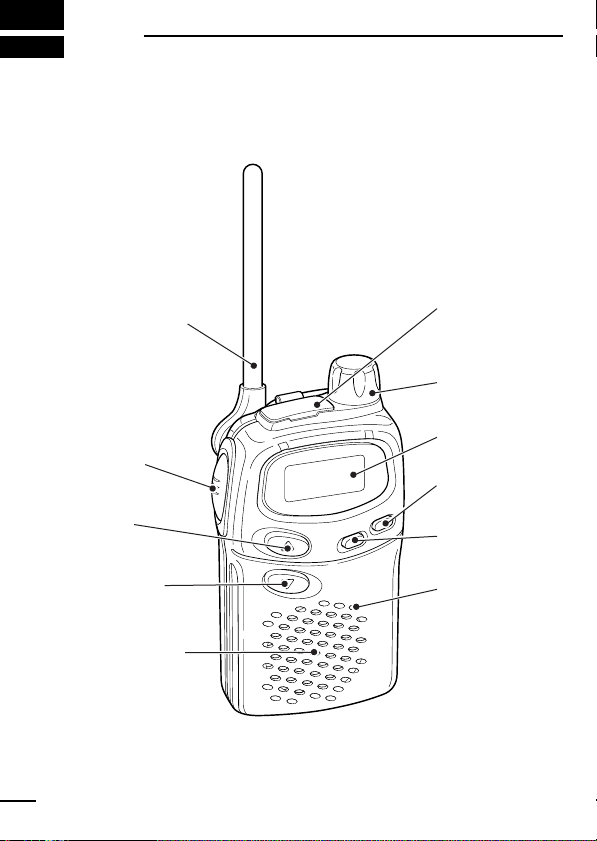
1
q ANTENNA
w [PTT]
e [UP]
r [DOWN]
t SPEAKER
!0 [VOL]
o FUNCTION
DISPLAY
i [POWER]
u [MODE]
y MIC
!1 SP/MIC
JACKS
‘‘
PANEL DESCRIPTION
Switches, controls, keys and connectors
1
Page 7

PANEL DESCRIPTION
q ANTENNA
Extend the antenna completely when using the transceiver.
• The antenna collapses completely into the transceiver body for carrying purposes.
• The antenna can be adjusted 90 degrees from the regular position
when operating the transceiver in a horizontal position.
w PTT SWITCH [PTT]
• Push and hold to transmit; release to receive.
e CHANNEL UP SWITCH [UP]/[Y]
• Push to increment the operating channel.
• Push and hold to increment the operating channel continuously.
r CHANNEL DOWN SWITCH [DOWN]/[Z]
• Push to decrement the operating channel.
• Push and hold to decrement the operating channel continuously.
t SPEAKER
y MICROPHONE [MIC]
u MODE SWITCH [MODE]
• Push to toggle between Group mode and Normal mode. (p. 11)
• Push and hold for 1 sec. to force the squelch open; push and hold for 1
sec. to close it again. (p. 8)
i POWER SWITCH [POWER]
• Push to turn the power ON.
• Push and hold this key to toggle the key lock function ON/OFF.
(p. 16)
o FUNCTION DISPLAY (p. 3)
!0 VOLUME CONTROL [VOL]
Rotate clockwise to increase and counterclockwise to decrease volume.
!11 EXTERNAL SPEAKER AND MICROPHONE JACKS
Connect an optional speaker-microphone or headset, if desired.
1
2
Page 8
1
q
we
r
t
i
o
u
y
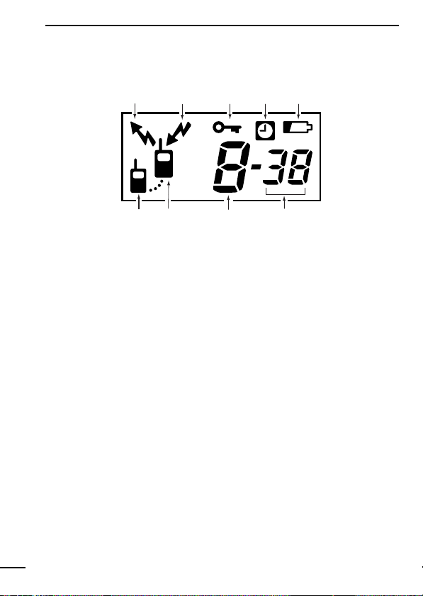
PANEL DESCRIPTION
‘‘
Function display
q TRANSMIT INDICATOR
Appears during PTT on.
w BUSY INDICATOR
Appears while receiving a signal or when the squelch is open.
e KEY LOCK INDICATOR
Appears during key lock function ON.
r AUTO POWER OFF INDICATOR
Appears while the auto power off function is ON. (see p. 15)
t LOW BATTERY INDICATOR
Appears or flashes when battery power has decreased to a specified
level.
y GROUP NUMBER INDICATION
One of 01 to 38 appear while the Group function is turned ON.
u CHANNEL NUMBER INDICATOR
Indicates operating channel number.
i POWER ON INDICATOR
Appears while the power is ON.
o ANSWER BACK INDICATOR (see p. 17)
• Appears when you and your group are in the conversation area.
• Blinks when you or your group is out of the conversation area.
3
Page 9
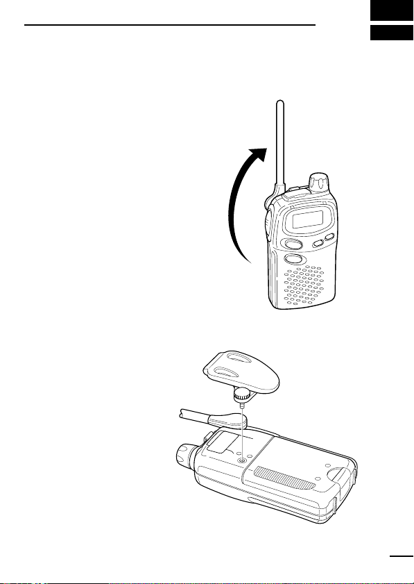
ACCESSORIES
‘‘
Accessory attachment
D Antenna
Adjust the antenna position as
shown at right.
Keep the jack cover attached
when jacks are not in use to
avoid bad contacts.
D Belt clip
Attach the belt clip using the
supplied screws. Conveniently
attaches to your belt.
2
4
Page 10
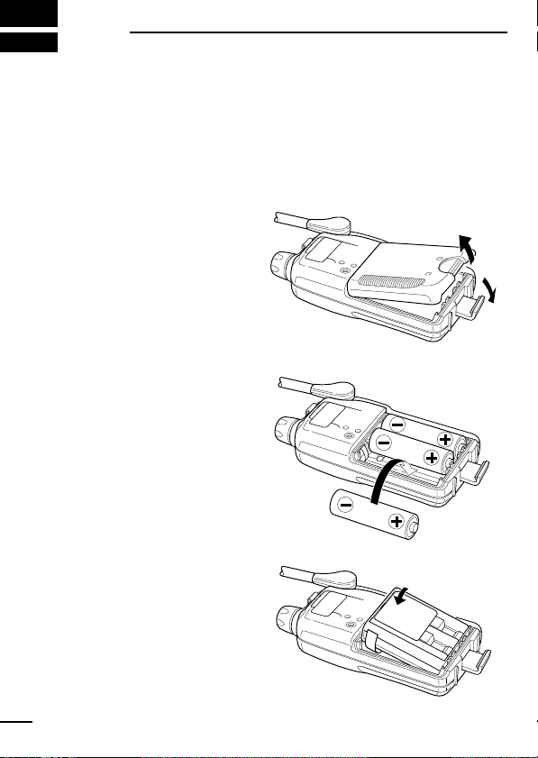
3
‘‘
BATTERY PACKS
Installing batteries in the battery
case
Install 3 R6(AA) size alkaline, dry cell batteries or the BP-202 BAT-
TERY PACK
q Remove the battery
case cover from the
transceiver.
w Install 3×R6(AA) size
dry cell, alkaline batteries or the BP-202.
• Be sure to observe
the correct polarity.
as illustrated below.
NOTE: Keep battery contacts clean. It’s a good
idea to clean battery terminals once a week.
5
BP-202
Page 11

BATTERY PACKS
‘‘
Battery pack charging
The optional BP-202 BATTERY PACK
batteries and can be charged approx. 300 times. Charge the battery
pack before first operating the transceiver or when the battery pack
becomes exhausted.
If you want to be able to charge the battery pack more than 300
times, the following points should be observed:
1. Avoid overcharging. The charging period should be less than 48
hours.
2. Use the battery until it becomes almost completely exhausted
under normal conditions. We recommend battery charging just
after transmitting becomes impossible.
‘‘
Battery pack life
If your battery pack seems to have no capacity even after being
fully charged, completely discharge it by leaving the power ON all
day. Then, fully charge the battery pack again.
If the battery pack still does not retain a charge (or very little), a new
battery pack must be purchased.
‘‘
Battery pack CAUTION
NEVER short terminals of the battery pack (or charging terminals of
the transceiver). Also, current may flow into nearby metal objects,
so be careful when placing battery packs ( or the transceiver) in
handbags, etc. Simply carrying with or placing near metal objects
such as necklace, etc. causes shorting. This will damage not only
the battery pack but also the transceiver.
includes rechargeable Ni-Cd
3
6
Page 12

BATTERY PACKS
*
3
‘‘
Charging connections
D Rapid charging with the BC-119L/BC-119+AD-89
q Insert the optional AD-89 DESKTOP CHARGER ADAPTER into
the charging slot of the BC-119.
• The BC-119L comes preinstalled with the AD-89
ADAPTER.
w Insert the battery pack, either by itself or attached to the trans-
ceiver, into the charger.
(See BC-119/L instructions.)
IC-446S
BP-202
CHARGING
*NOTE: Put the Ni-Cd
battery adapter into the
AD-89 rear slot when
the BP-202 is attached
to the transceiver.
AC adapter
AD-89
BC-119
7
Page 13

BASIC OPERATION
w
e
q
UP
DOWN
M
O
D
E
P
O
W
E
R
Busy indicator
appears.
UP
DOWN
M
O
D
E
P
O
W
E
R
‘‘
Power ON
➥ Push [POWER] for 1sec. to turn the
power ON.
• The power on indicator and operating channel number appear on
the display.
‘‘
Adjusting the volume
q Push and hold [MODE] for
1sec. to open the squelch.
• Busy indicator appears on
the display while the squelch is
open.
w Adjust the audio to a suitable level
e Push and hold [MODE] for 1sec. to
VOL].
using [
close the squelch.
4
✔ What is squelch?
A squelch circuit allows you to mute undesired noise while receiving no signal and emit audio while receiving signals.
This provides quiet standby. The [
squelch setting. This is useful to listen to weak signals that do
not open the squelch.
MODE] key changes the
8
Page 14

BASIC OPERATION
UP
DOWN
M
O
DE
P
O
W
E
R
4
‘‘
Selecting the operating channel
Push [UP]/[Y] or [DOWN]/[Z] keys sev-
eral times until the desired operating
channel number appears on the display.
• While pushing and holding [
DOWN]/[Z] keys, the displayed chan-
[
UP]/[Y] or
nel changes continuously until channel number “ 1 ” appears.
If you want to keep the automatic selection, release the [
DOWN]/[Z] keys then push and hold them again.
[
UP]/[Y] or
• When displayed channel stops at channel number “1”, a warning
beep is emitted.
NOTE:
• The transceiver has 8 operating frequency channels.
• The selected channel is memorised when you turn off the
transceiver.
• The transceiver has an auto power save function to conserve
the battery power. The power save function activates automatically when no signal is received for 5 sec.
9
Page 15

RECEIVE AND TRANSMIT
UP
DOWN
M
O
D
E
P
O
W
E
R
UP
DOWN
M
O
D
E
P
O
W
E
R
Busy indicator
appears.
q Push and hold [MODE] 1sec.
to open the squelch.
• Adjust volume to the desired
audio level. (See p. 8)
w Select a desired operating channel.
When a signal is received:
• Squelch opens and audio is emitted
from the speaker.
• Further adjustment of [
necessary at this point.
• “BUSY” indicator appears on the display.
e Push and hold [
PTT] to transmit then
speak into the microphone.
• Do not hold the transceiver too close
to your mouth or speak too loudly.
This may distort the signal.
• The transmit indicator “” appears
on the display.
] to return to receive.
r Release [
PTT
Time-Out Timer (TOT)
The transceiver has time-out timer function. This function prevent continuous, extend transmissions. This timer turns a transmission OFF 3 min. after it starts.
A warning beep sounds 10 sec. before the limit is reached and
the time-out timer turns OFF the transmission automatically. The
end beep emits to announce the end of the transmission.
VOL] may be
5
10
Page 16

6
UP
DOWN
M
O
D
E
P
O
W
E
R
q
w
w
‘‘
GROUP MODE (CTCSS)
Setting the group code
The IC-446S is equipped with 38 group codes. Group mode operation provides communication with silent standby since you will only
receive calls from group members using the same group number.
First of all, set the same group code number for all group member’s
transceivers.
Turn ON the group mode operation:
q Push [MODE] to enter set mode.
•“ --- ” (group mode OFF) appears on
the display.
w Push [UP]/[Y] or [DOWN]/[Z] to select
the desired code number.
e Push [MODE] to set the group code
number.
Cancel the group mode operation:
q Push [MODE] to enter set mode.
• Code number disappears on the display.
w Push [UP]/[Y] or [DOWN]/[Z] to select
“ --- ” (group mode OFF).
e Push [MODE] to cancel the group
mode.
11
NOTE: Only stations with the same
group channel number can be heard during group mode operation, even when the busy indicator appears on the display.
Page 17

GROUP MODE (CTCSS)
✔ What is CTCSS (Continuous Tone Coded Squelch Sys-
tem) GROUP MODE ?
CTCSS (Continuous Tone Coded Squelch System) GROUP
MODE allows communication with silent stand by. Only signals
containing your group code can open the squelch.
This conveniently eliminates unwanted audio and is useful in
group activities or security related activities where unwanted
output can be a problem. Note that CTCSS group mode is not
private—anyone can receive your calls.
The IC-446S is equipped with 38 tone codes for CTCSS
GROUP MODE use. Selecting a code applies it to all 8 operating channels. Each push of [PTT] superimposes your group
code over your transmit signal; and, only signals containing the
same code can open your squelch. To temporarily hear all signals (including noise) push and hold [MODE]. Do not use
CTCSS GROUP MODE if you want to be able to hear signals
on all channels.
6
12
Page 18

GROUP MODE (CTCSS)
6
D CTCSS code table
CH Freq. CH Freq. CH Freq. CH Freq.
01
02
03
04
05
06
07
08
09
10
67.0
71.9
74.4
77.0
79.7
82.5
85.4
88.5
91.5
94.8
11
12
13
14
15
16
17
18
19
20
97.4
100.0
103.5
107.2
110.9
114.8
118.8
123.0
127.3
131.8
21
22
23
24
25
26
27
28
29
30
136.5
141.3
146.2
151.4
156.7
162.2
167.9
173.8
179.9
186.2
31
32
33
34
35
36
37
38
---
192.8
203.5
210.7
218.1
225.7
233.6
241.8
250.3
OFF
(unit: Hz)
✔ Talk Range
The IC-446S is designed to maximize performance and improve transmission range in the field. However, the single
most important factor in transmit range (talk power) is your
surrounding environment. These radios are “line of sight” radios and as such, transmission range is influenced by the degree to which you can “see” the other communicating party.
Large concrete structures and heavy foliage or transmission
from inside a building or vehicle will reduce your talk power.
13
• Optimal range: wide, open areas free of obstructions.
• Medium range: large buildings or trees blocking your line of
sight.
• Minimum range: mountainous areas or areas of heavy foliage.
Page 19

‘‘
UP
DOWN
M
O
D
E
P
O
W
E
R
UP
DOWN
M
O
D
E
P
O
W
E
R
Smart-Ring
RING FUNCTION
7
The ring function has an answer back feature. This allows you to
confirm whether or not a call has reached the receiving party even
if the operator is temporarily away from the transceiver.
q Set the same group channel number for
all of your group transceivers. (See left.)
w While pushing [PTT], push [UP]/[Y] .
• A beep is emitted and “” blinks on
the display.
e Release the [PTT].
• When a member of your group answers your call, the transceiver emits
beep tones for 10 sec. and blinks “”.
• When no answer comes back, the
transceiver emits short faint beep tones.
r Push [PTT] to answer and to stop the beeps and flashing.
NOTE: This function is available only when the called station
has set the same group number and the same operating channels as you.
‘‘
Call-Ring
Sends the ring tones during transmit
mode.
➥ While pushing [PTT], push [DOWN]/[Z]
to send a ring tone.
• The ring tone is emitted while pushing
[DOWN]/[Z].
• The microphone signal is automatically cut while pushing [DOWN]/[Z].
14
Page 20

8
UP
DOWN
M
O
DE
P
O
W
E
R
UP
DOWN
M
O
D
E
P
O
W
E
R
q
q
w
w
UP
DOWN
M
O
DE
P
O
W
E
R
‘‘
OTHER FUNCTIONS
Initial set mode
Initial set mode is accessed at power ON and allows you to set seldom changed settings. In this way you can “customize” transceiver
operations to suit your preferences and operating style.
D Auto power OFF
This function sets the transceiver to automatically turn OFF after 2 hours elapse.
q While pushing [MODE], push [POWER]
ON to toggle the function ON or OFF.
w ““ appears on the display.
•“Auto power OFF” function retains its
setting after power OFF.
D Ring tone type
You can select the ring tone from one of
10 sounds.
q While pushing
[UP]/[Y], push [POWER]
ON.
w Push [
UP]/[Y] or [DOWN]/[Z] to select
the ring sound.
D Beep tones ON/OFF
Confirmation beep tones normally sound
when you push a key. These can be
turned ON or OFF.
➥ While pushing [
[POWER].
15
DOWN]/[Z], push
Page 21

OTHER FUNCTIONS
UP
DOWN
M
O
DE
P
O
W
E
R
Lock indicator
appears.
D Lock function
This function electronically locks all keys and switches to prevent
accidental channel changes and function access.
➥ Push and hold [POWER] for 2 sec. to turn the lock function ON
and OFF.
“” appears on the display.
- Only [POWER], [MODE] and
[PTT] are functional.
- The Ring function is also available.
(See p. 14)
8
16
Page 22

OTHER FUNCTIONS
UP
DOWN
M
OD
E
P
O
W
E
R
appears.
8
‘‘
ATS (Automatic Transponder System)
This allows you to confirm whether or not a call has reached the receiving party even if the operator is temporarily away from the
transceiver. No “Ring” tone is emitted with this function.
➥ Push [MODE], while [PTT] is
ON to turn the function
ON/OFF.
•“ ” appears on the display.
• The transceiver starts to send a
searching signal every 60 sec.
- When the transceiver receives an
answer back signal, “” stays on
the display until the next search
transmit.
- If no reply is received, “” blinks until the next search transmit.
NOTE: Above setting is for the calling station only. A called party
automatically sends an answer back signal without any presettings.
All IC-446S’s operating on the same operating channel will answer back to your call in your communication area.
‘‘
LCD backlight
➥ Automatically turns ON for 5 sec. when you push any key, ex-
cept [PTT].
‘‘
Auto power save
➥ The power save function reduces the current drain to conserve
battery power.
- The function automatically turns ON when no operation is performed or no signal is received for 5 sec.
17
Page 23

OTHER FUNCTIONS
UP
DOWN
M
OD
E
P
O
W
E
R
RPT
‘‘
Low Battery indicator
➥ Appears when the battery is nearing
exhaustion.
• A warning beep is emitted while turning the power ON.
➥ Appears and blinks when battery re-
placement is necessary.
In an extreme low temperature environment (around –20°C), the
capacity of Alkaline or dry cell batteries may exhaust quickly. In
such case, we recommend to replace the batteries, when the
“Low Battery Indicator” appears during transmission.
‘‘
Resetting the transceiver
Initialize the operating conditions before
using the transceiver for the first time, or if
the function display shows erroneous information.
➥ While pushing [
DOWN]/[Z] and
[MODE], push [POWER] ON to initialize the transceiver.
CAUTION: Resetting the transceiver returns all settings to their
defaults.
8
18
Page 24

OTHER FUNCTIONS
A
OFF ON
LOCK
B
Lock switch:
Locks all
switches
except [PTT]
Earphone
jack
PTT switch
8
‘‘
Optional HM-75A functions
The optional HM-75A allows you to remotely select operating channels, open the squelch, etc. The switches on the HM-75A function
as follows.
CAUTION: When connecting the HM-75A to the transceiver,
make sure that power to the transceiver is turned OFF, otherwise the transceiver may malfunction.
19
SWITCH
A
B
UP
DOWN
NORMAL
Smart-Ring
Open squelch
Change the operating channel
number up.
Change the operating channel
number down.
While holding [PTT]
No function
No function
Smart-Ring
Call-Ring
Page 25

SPECIFICATIONS
9
GENERAL
• Frequency coverage : 446.00625–446.09375 MHz
• Mode : F3E (FM)
• No. of operating ch. : 8 (simplex)
• Frequency stability : ±2.5 kHz (–20˚C to +55˚C),
±1.5 kHz (0˚C to +30˚C)
• Frequency resolution : 12.5 kHz
• Power supply requirement: 4.5 V (R6
• Current drain : Less than 500 mA
• Operating temp. range : –20˚C to +55˚C (–4˚F to +131˚F)
• No. of CTCSS freq. : 38
• Dimensions :
(projections not included)
• Weight : 180 g (including 3 R6 batteries)
55.5(W)×102.5(H)×26.5(D) mm
× 3)
or BP-202
TRANSMITTER
• Output power : Less than 500 mW ERP
• Maximum deviation : ±2.5 kHz
• Spurious emissions : Less than 250 nW
• Ext. mic. connector : 3-conductor 2.5 (d) mm/2.2 kΩ
RECEIVER
• Receive system : Double-conversion superheterodyne
• Sensitivity : Less than 26.5 dBµV/m
(20 dB SINAD)
• Selectivity : More than 8.5 kHz/–6 dB
• Spurious and image rejection: Better than 91.29 dBµV/m
• Adjacent ch. rejection : Better than 81.29 dBµV/m
• Intermodulation rejection: Better than 86.29 dBµV/m
• Audio output power : More than 100 mW at 10 %
(at 4.5 V DC) distortion with an 8 Ω load
• Ext. speaker connector : 2-conductor 3.5 (d) mm/8 Ω
All stated specifications are subject to change without
notice or obligation.
20
Page 26

10
HM-46
HM-75A
HM-54
HS-85 HEADSET
• PTT switch
• VOX
• One-touch PTT for
hands-free operation
Remote control
capability.
(see p. 17 for details)
OPTIONS
D Battery packs
BP-202 Ni-Cd BATTERY PACK
3.6V/ 700 mAh rapid charge battery pack. (p. 6–7)
D Chargers
BC-119 DESKTOP CHARGER + AD-89 DESKTOP CHARGER
ADAPTER
Rapidly charge battery packs in 1 to 1.5 hrs. An AC adapter is
packed with the BC-119. The AD-89 must be used with the BC-119
for charging the battery pack. The CP-17L or OPC-515 can be used
instead of the supplied AC adapter. (p. 7)
BC-119L
AD-89 BATTERY PACK ADAPTER attached to BC-119 DESKTOP
CHARGER. (p. 7)
DESKTOP CHARGER
D Speaker-microphones
21
Page 27

MEMO
‘‘
Channel number and group number
Use this page to record your group operating channel number
(see p. 9) and group channel number (p. 11) for your reference.
Operating channel number
Group code number
11
ï Channel frequency list
ch Freq.(MHz)
1
2
3
4
5
6
7
8
446.00625
446.01875
446.03125
446.04375
446.05625
446.06875
446.08125
446.09375
22
Page 28

11
MEMO
23
Page 29

MEMO
11
24
Page 30

12
CE
ABOUT CE
CE Versions of the IC-446S which display the “CE”
symbol on the serial number seal, comply with the
essential requirements of the European Radio and
Telecommunication Terminal Directive 1999/5/EC.
This warning symbol indicates that this equipment
operates in non-harmonised frequency bands and/or
may be subject to licensing conditions in the contry
of use. Be sure to check that you have the correct
version of this radio or the correct programming of
this radio, to comply with national licensing requirement.
25
Page 31

DECLARATION
OF CONFORMITY
We Icom Inc. Japan
1-1-32, Kamiminami, Hirano-ku
Osaka 547-0003, Japan
Kind of equipment:
PMR446 FM TRANSCEIVER
This compliance is based on conformity with the following harmonised
standards, specifications or documents:
i) ETS300 279 v1.2.1(1999-02) (EMC product standard)
ii) EN60950 August 1992 (Safety of imformation technology equipment)
iii)ETS300 296 December 1994 (Radio equipment for analogue speech)
iv)
v)
Type-designation: iC-446s
Signature
Authorized representative name
Place and date of issue
T. Aoki
General Manager
Icom (Europe) GmbH
Himmelgeister straße 100
D-40225 Düsseldorf
Düsseldorf 25th Sept. 2000
Icom (Europe) GmbH
Declare on our sole responsability that this equipment complies the
essential requirements of the Radio and Telecommunications Terminal
Equipment Directive, 1999/5/EC, and that any applicable Essential Test
Suite measurements have been performed.
Version (where applicable):
0560
CE
12
26
Page 32

Count on us!
A-5630H -1EU-t
Printed in Japan
© 1999 Icom Inc.
1-1-32 Kamiminami, Hirano-ku, Osaka 547-0003 Japan
 Loading...