

Page 1

INSTRUCTION MANUAL
UHF CB TRANSCEIVER
i440
Page 2
IMPORTANT
OPERATING NOTES
READ ALL INSTRUCTIONS carefully and com-
pletely before using the transceiver.
SAVE THIS INSTRUCTION MANUAL — This
instruction manual contains important oper ating instructions
for the IC-440 UHF CB TRANSCEIVER.
EXPLICIT DEFINITIONS
WORD DEFINITION
RWARNING
CAUTION
NOTE
Icom, Icom Inc. and the logo are registered trademarks of Icom
Incorporated (Japan) in the United States, the United Kingdom, Germany,
France, Spain, Russia and/or other countries.
Personal injury, fire hazard or electric
shock may occur.
Equipment damage may occur.
If disregarded, inconvenience only. No risk
of personal injury, fi re or electric shock.
BUSY CHANNEL
Always listen to a channel (or observe the channel busy indicator on the
display) to ensure that the channel is not already in use before transmitting.
CALLING CHANNELS (CB-11,CB-40)
In Australia channel 11 is the customary calling channel for establishing
communication and channel 40 is the customary road vehicle channel.
EMERGENCY CHANNELS (CB-05, CB-R5, CB-35)
In Australia except in an emergency, a CB transmitter must not be operated on UHF emergency channels 5 & 35.
NOTE: if the Radio is switched off while on an Emergency channel,
the Radio when switched on again, will be on the (software preset
channel) CB-11.
DATA CHANNELS (CB-22, CB-23)
No voice transmissions are permitted on data channels 22 and 23. (Note:
Voice operation is inhibited on channels 22 and 23).
REPEATER CHANNELS (CB-R1 to CB-R8)
UHF CB repeaters provide greater range through a base station that retransmits the signal. Repeaters operate utilizing two channels (repeater
input/ repeater output channels). It is important to avoid operation on
locally used repeater input channels (which will be in the range channels
31 to 38) or locally used repeater receiving channels (which will be in
the range channels 1 to 8), unless long distance communication via the
repeater facility is specifi cally required. (Please also see: Repeater Operation, Repeater Search Scan).
CLASS LICENCE
The citizen band radio service is licensed in Australia by The ACMA Radiocommunications (Citizens Band Radio Stations) Class Licence and in New
Zealand by MED General User Radio Licence for Citizens Band Radio and
operation is subject to conditions contained in those licences.
i
Page 3

PRECAUTIONS
R WARNING! NEVER connect the transceiver to an AC
outlet. This may pose a fi re hazard or result in an electric shock.
R WARNING! NEVER operate the transceiver while
driving a vehicle. Safe driving requires your full attention—
anything less may result in an accident.
NEVER connect the transceiver to a power source of
more than 27.6 V DC. This will damage the transceiver.
NEVER connect the transceiver to a power source using
reverse polarity. This will damage the transceiver.
NEVER cut the DC power cable between the DC plug and
fuse holder. If an incorrect connection is made after cutting,
the transceiver may be damaged.
NEVER expose the transceiver and microphone to rain,
snow or any liquids. The transceiver and microphone may be
damaged.
NEVER operate or touch the transceiver and microphone
with wet hands. This may result in an electric shock or damage
the transceiver and microphone.
NEVER place the transceiver where normal operation of the
vehicle may be hindered or where it could cause bodily injury.
DO NOT push the PTT when not actually desiring to transmit.
DO NOT allow children to play with any radio equipment
containing a transmitter.
DO NOT operate the transceiver for extended periods
without running the vehicle’s engine. The transceiver’s power
consumption may soon exhaust the vehicles battery.
DO NOT use or place the transceiver in direct sunlight or
in areas with temperatures below –10°C or above +60°C.
DO NOT set the transceiver in a place without adequate
ventilation. Heat dissipation may be affected, and the transceiver may be damaged.
DO NOT use the chemical agents such as benzine or alcohol
when cleaning, as they can damage the transceiver’s surfaces.
USE Icom microphones only (supplied or optional). Other
manufacturer’s microphones have different pin assignments
and may damage the transceiver if attached.
ii
Page 4

TABLE OF CONTENTS
IMPORTANT ··························································································· i
EXPLICIT DEFINITIONS ········································································ i
OPERATING NOTES·············································································· i
PRECAUTIONS ······················································································ ii
TABLE OF CONTENTS ········································································· iii
1 ACCESSORIES AND CONNECTION ········································· 1–5
■ Supplied accessories ··································································· 1
■ Installation ···················································································· 1
2 PANEL DESCRIPTION ······························································ 6–13
■ IC-440 front and rear panels ························································· 6
■ HM-182 front and top panels ························································ 7
■ Function display ·········································································· 10
■ Programmable function keys ······················································ 12
3 BASIC OPERATION ································································ 14–19
■ Turning power ON ······································································· 14
■ Volume selection ········································································· 14
■ Channel selection ······································································· 14
■ Receiving and transmitting ························································· 15
■ Priority channel setting ······························································· 17
■ Monitor function ·········································································· 18
■ Lock function ·············································································· 18
■ Adjusting the squelch level ························································· 18
■ Display backlighting ···································································· 19
■ Set mode ···················································································· 19
4 REPEATER OPERATION ······························································ 20
■ Repeater operation ····································································· 20
■ Accessing a repeater ·································································· 20
5 SCAN OPERATION ································································· 21–25
■ Scan types ·················································································· 21
■ Scanning preparation ································································· 22
■ Open scan ·················································································· 23
■ Group and priority scans ···························································· 24
■ Repeater search scan ································································ 25
6 TONE SQUELCH OPERATION ··············································· 26–28
■ Tone squelch operation ······························································· 26
■ Pocket beep operation ································································ 28
7 SELCALL OPERATION ··························································· 29–33
■ General ······················································································· 29
■ Calling operation ········································································· 29
■ When receiving a call ································································· 32
■ Quiet mode operation ································································· 33
■ Stun function··············································································· 33
8 OTHER FUNCTIONS ······························································· 34–39
■ Smart-Ring and ATS (Automatic Transponder System) ·············· 34
■ RX frequency setting (for RX channels only) ····························· 35
■ Wide/Narrow function ································································· 37
■ PTT hold function ······································································· 38
■ Data cloning················································································ 38
■ All reset······················································································· 39
9 SET MODE ·············································································· 40–46
■ Set mode ···················································································· 40
■ SET mode items ········································································· 41
10 MAINTENANCE ······································································· 47–48
■ Troubleshooting ·········································································· 47
■ Fuse replacement ······································································· 48
11 SPECIFICATIONS AND OPTIONS ········································· 49–50
■ Specifi cations ············································································· 49
■ Options ······················································································· 50
12 WARRANTY AND PRODUCT REGISTRATION ····················· 51–54
INDEX ···························································································· 57–59
iii
Page 5
ACCESSORIES AND CONNECTION
1
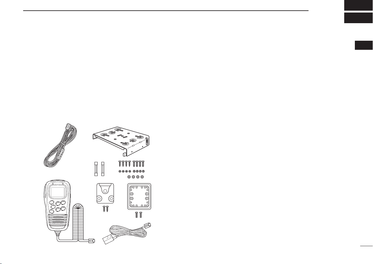
■ Supplied accessories
q DC power cable (3 m) ····················································· 1
w Mounting bracket ····························································· 1
e Microphone (HM-182) ····················································· 1
r Fuses (FRG 5 A) ····························································· 2
t Mounting screws, nuts and washers ························· 1 set
y Microphone hanger set ··················································· 1
u Microphone hanger attachment plate ·····························1
i Microphone cable (2.5 m) ··············································· 1
qw
r
e
y
t
u
i
■ Installation
ï Location
Select a location which can support the weight of the transceiver and does not interfere with driving. We recommend
the locations shown in the diagram at p. 2.
NEVER place the transceiver or microphone where normal
operation of the vehicle may be hindered or where it could
cause bodily injury.
NEVER place the transceiver or microphone where air bag
deployment may be obstructed.
DO NOT place the transceiver or microphone where hot or
cold air blows directly onto it.
DO NOT place the transceiver or microphone in direct sunlight.
1
1
Page 6
ACCESSORIES AND CONNECTION
1
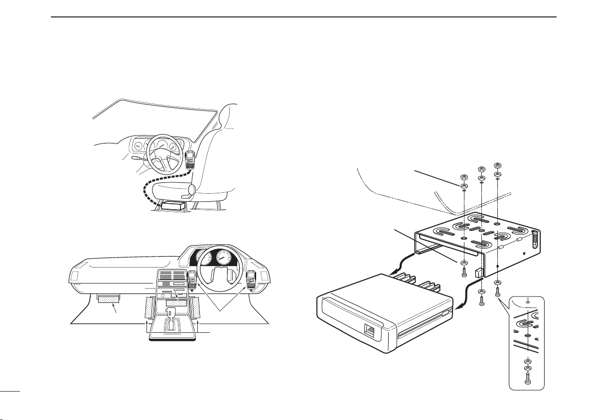
ï Installation methods
<Sample 1: IC-440 is installed under a driver’s seat.>
<Sample 2: IC-440 is installed under a dash box, etc.>
Main unit
Main unit
Microphone
Main unit
D Using the mounting bracket
q Drill 3 holes where the mounting bracket is to be installed.
• Approx. 5.5–6 mm (1⁄4´´) when using nuts; approx. 2–3 mm
1
(
⁄8´´) when using self-tapping screws.
w Insert the supplied screws, nuts and washers through the
mounting bracket and tighten.
e Insert the mounting bracket’s rail to the transceiver’s slot,
then slide the transceiver to attach with the mounting bracket.
Flat washer
Spring washer
When using
self-tapping screws
2
Page 7
ACCESSORIES AND CONNECTION
1
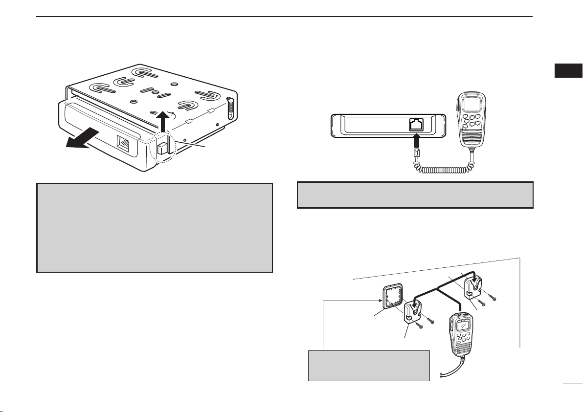
Release lever
NOTE
• When detaching the transceiver from the mounting bracket,
push up and hold the release lever, then pull the transceiver
in the direction of the arrow.
• The mounting bracket can be attached even if upside down.
When detaching the transceiver from the bracket in this case,
push down and hold the release lever, then pull the transceiver to the front.
D Microphone connection
Connect the supplied microphone as illustrated below.
CONVENIENT! The supplied OPC-647 MICROPHONE CABLE is
available to extend the microphone cable.
D Microphone hanger attachment
Attach the supplied microphone hanger (with the microphone
hanger attachment plate) as illustrated below.
Microphone hanger
attachment plate
Microphone hanger
Put double-faced tape* on the
back side of the attachment plate.
*Not supplied.
Microphone
hanger
HM-182
1
3
Page 8
ACCESSORIES AND CONNECTION
1
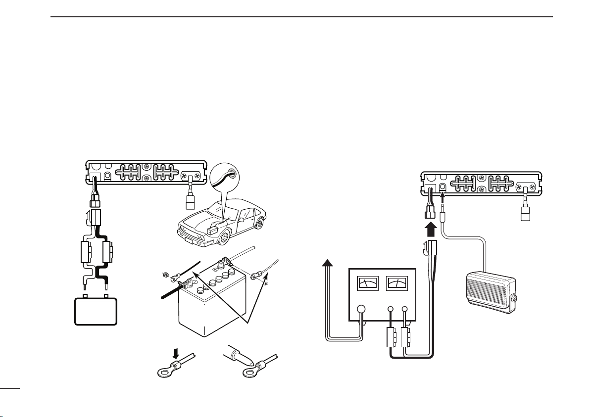
D Battery connection
R WARNING NEVER remove the fuse holders from the DC
power cable.
DO NOT use the cigarette lighter socket for power connection. (See p. 6 for details)
Attach a rubber grommet when passing the DC power cable
through a metal plate to prevent a short circuit.
• Connecting to a DC power source
Grommet
IC-440
+ red
12 V or 24 V
NOTE:
Use terminals for the
cable connections.
_ black
Fuses
5 A
WARNING!
NEVER
remove the
fuse holders.
_ black
12 V or 24 V
battery
DC power cable
Crimp Solder
+ red
Supplied
D DC power supply connection
R WARNING NEVER remove the fuse holders from the DC
power cable.
Use a 13.8 V or 27.6 V DC power supply with at least 3 A
capacity.
Make sure the ground terminal of the DC power supply is
grounded.
• Connecting to a DC power supply
IC-440
to an
AC
outlet
DC power supply
13.8 V or 27.6 V
+
_
+ red
_ black
Optional speaker
(SP-22)
Fuses
5 A
4
Page 9
ACCESSORIES AND CONNECTION
1
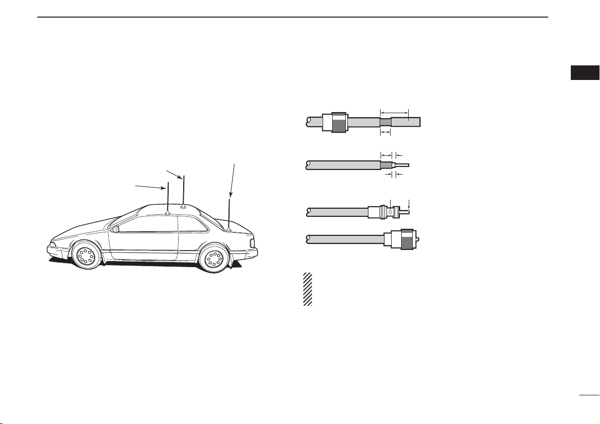
D Antenna installation
• Antenna location
To obtain maximum performance from the transceiver, select a high-quality antenna and mount it in a good location.
A non-radial antenna should be used when using a magnetic mount.
Roof-mount antenna
(Drill a hole or use a magnetic mount.)
Gutter-mount antenna
Trunk-mount
antenna
• Antenna connector
The antenna uses a PL-259 connector.
• PL-259 CONNECTOR
30 mm
Slide the coupling ring
q
down. Strip the cable jacket
Coupling ring
10 mm (soft solder)
10 mm
Soft
solder
1–2 mm
solder solder
and soft solder.
Strip the cable as shown at
w
left. Soft solder the center
connector.
e
Slide the connector body
on and solder it.
Screw the coupling ring
r
onto the connector body.
NOTE: There are many publications convering proper an-
tennas and their installation. Check with your local dealer
for more information and recommendations.
1
5
Page 10
2
PANEL DESCRIPTION
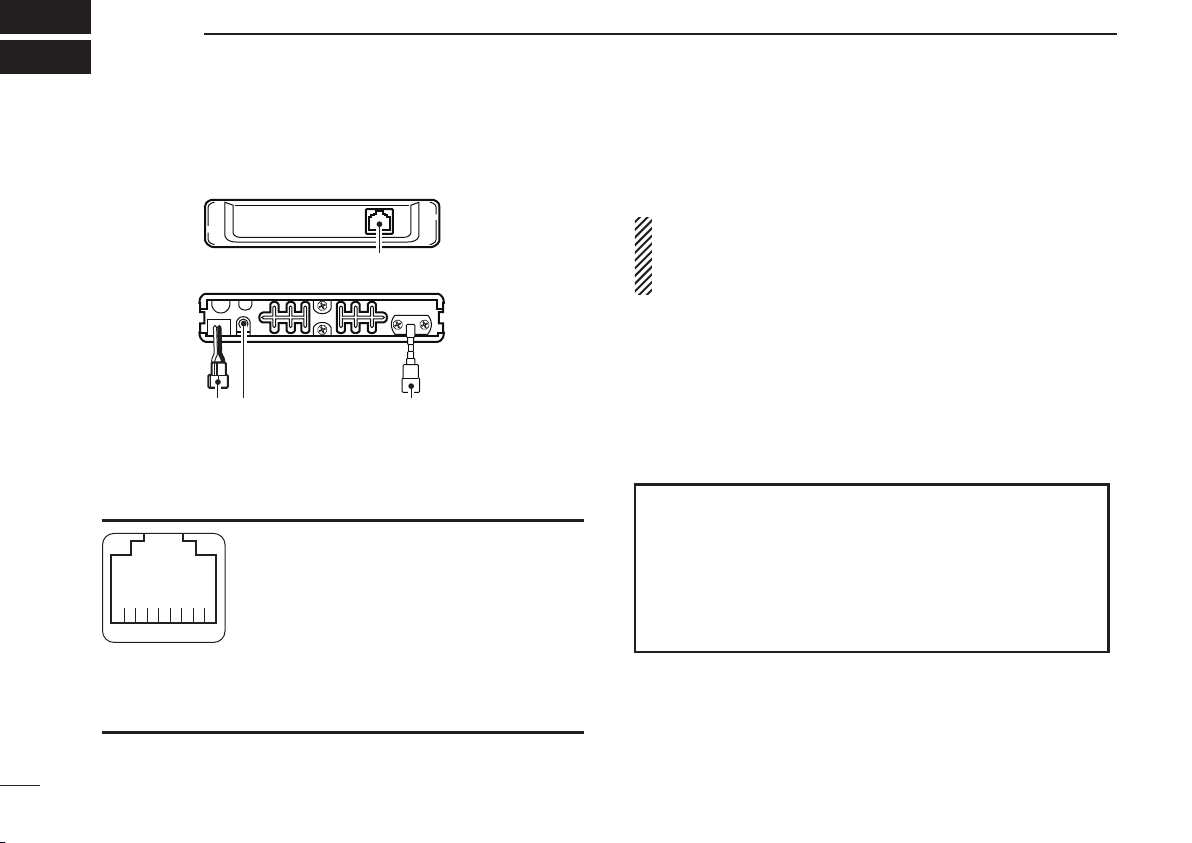
■ IC-440 front and rear panels
Front panel
Rear panel
w re
q MICROPHONE CONNECTOR
Connects the supplied microphone or cloning cable
(OPC-1122U).
q DC output (same voltage as connected
battery or DC power supply)
w TX line
e GND
r PTT
t GND (microphone ground)
Front panel view
y AF line
u POWER
i RX line
qi
q
w POWER RECEPTACLE
Accepts 13.8 V or 27.6 V DC with the supplied DC power
cable.
NOTE: DO NOT use a cigarette lighter socket as a power
source when operating in a vehicle. The plug may cause
voltage drops and ignition noise may be superimposed
onto transmit or receive audio.
e EXTERNAL SPEAKER JACK [SP]
Connects a 4 Ω speaker. (p. 4)
• Audio output power is more than 5.0 W.
r ANTENNA CONNECTOR
Connects a 50 Ω antenna with a PL-259 connector and a
50 Ω coaxial cable.
ANTENNA INFORMATION
For radio communications, the antenna is of critical importance, to maximize your output power and receiver
sensitivity. The transceiver accepts a 50 Ω antenna and
less than 1:1.5 of Voltage Standing Wave Ratio (VSWR).
High SWR values not only may damage the transceiver
but also lead to TVI or BCI problems.
6
Page 11
PANEL DESCRIPTION
2
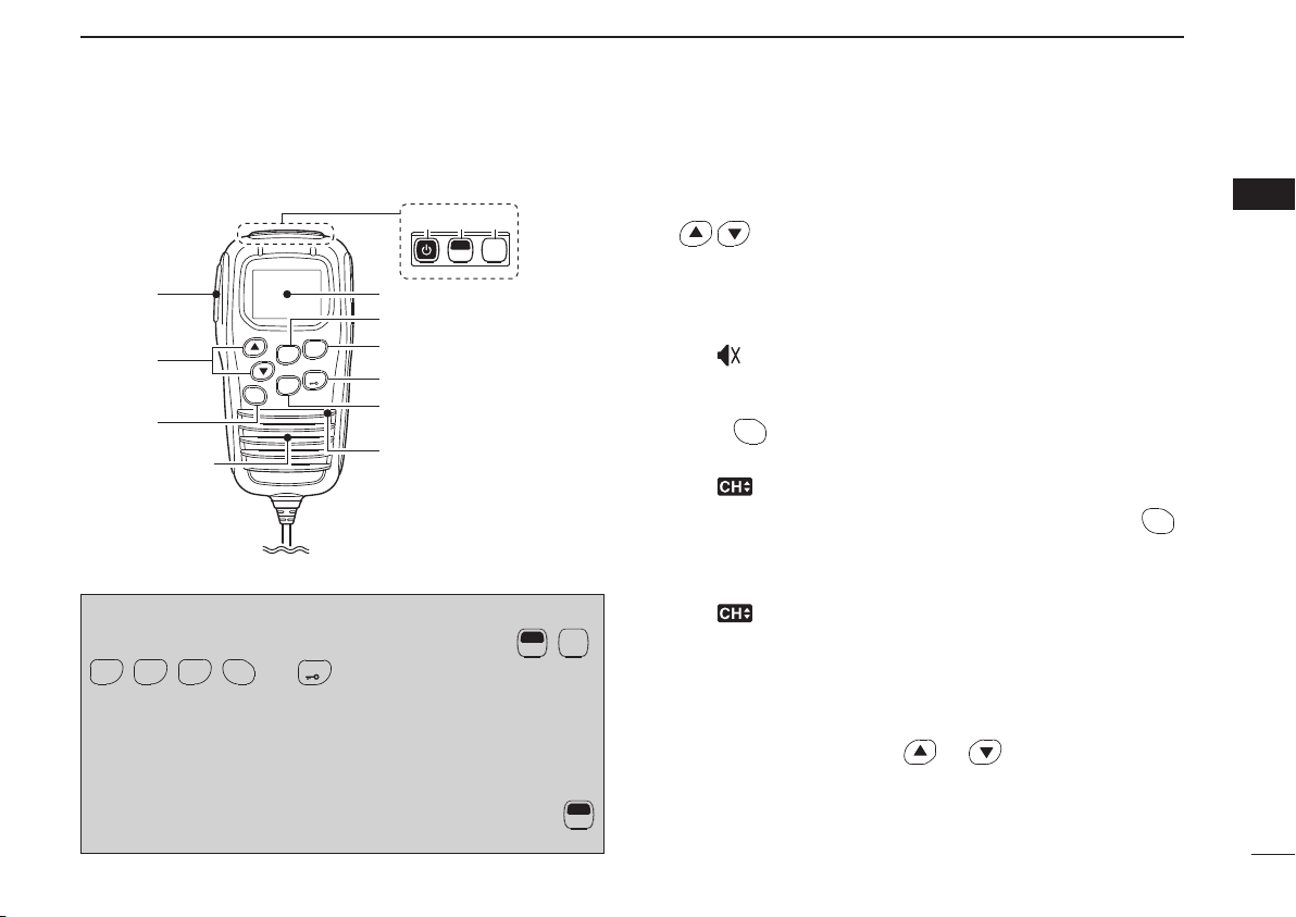
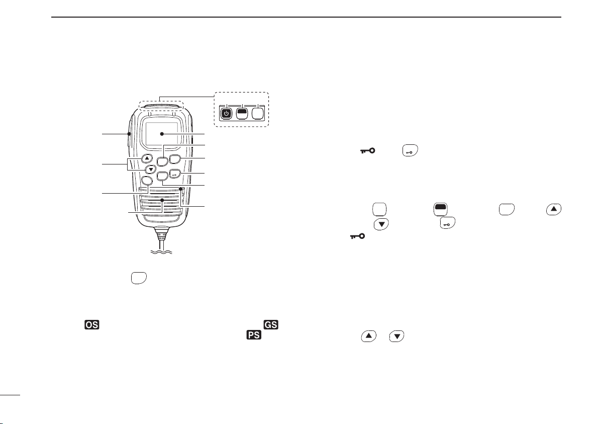
■ HM-182 front and top panels
o!0 !1
q
i
u
w
e
Speaker
SCAN
SETP
TAG
LOW
OGP
RS
CH
SQL
y
t
r
Microphone
PRIO
Information: Up to four desired functions, one each for
Normal and Function mode, can be re-assigned to
SCAN
TAG
CLONING SOFTWARE. (p. 12)
PRIO
OGP
,
RS
CH
SETP
,
,
SQL
and
LOW
keys with the optional CS-440
The default setting is used in this instruction manual, for
description.
N
: Stands for Normal mode operation.
F
: Stands for Function mode operation. (Push
(Function) to enter Function mode.)
MONI
F
TSQL
SET
MONI
F
,
TSQL
SET
SET
q PTT SWITCH [PTT] (p. 16)
Push and hold to transmit; release to receive.
w VOLUME CONTROL/CH UP/CH DOWN KEYS ([VOL])
/
2
Push to adjust the audio level, to select an operating
channel, set mode setting, etc. (pgs. 14, 19, 40)
[Volume adjust/set mode setting]
➥ Push to adjust the audio level (from 0 to 32).
• “ ” appears when the audio level is set to 0 (while muted).
➥ Push to select the set mode setting in the set mode.
[Channel selection]
CH
SQL
Push
, then push to select the operating channel.
(p. 14)
• “ ” appears when channel selection mode is selected.
e VOLUME/CHANNEL/SQUELCH SELECT KEY
CH
SQL
(Volume/Channel/Squelch select mode) (pgs. 14, 18)
➥ Push to toggle between volume and channel selection
mode.
• “ ” appears when channel selection mode is selected.
,
• If no key is pushed within 30 sec., channel selection mode
is cancelled.
(Squelch level select mode)
➥
Push and hold for 2 sec. to enter the squelch level setting mode, then push
or to set the squelch
level. (p. 18)
F
7
Page 12
PANEL DESCRIPTION
2
■ HM-182 front and top panels (Continued)
F (Quiet/ID-MR)
➥ Push to toggle the quiet function ON or OFF. (‘CB-XX’
displays when the CB channel is selected.) (p. 33)
o!0 !1
MONI
F
TSQL
SET
• “Q” appears when the quiet function is turned ON.
➥ Push and hold for 2 sec. to enter the received ID code
history indication mode. (p. 32)
q
w
e
Speaker
i
u
PRIO
SCAN
SETP
TAG
LOW
OGP
RS
CH
SQL
y
t
r
Microphone
• “NO ID” is displayed when no ID code is memorised.
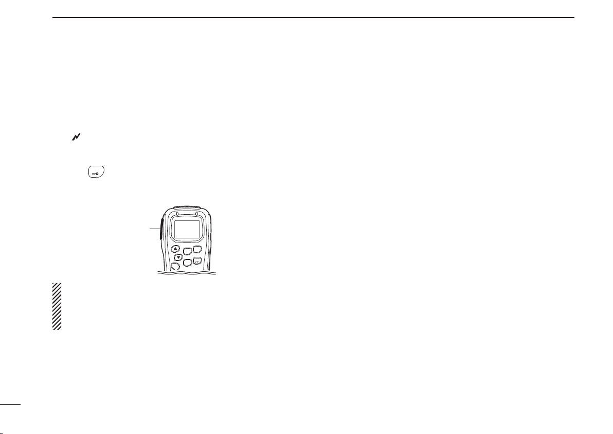
t LOW/“ ” KEY
LOW
N (RF Power/Lock)
➥ Push to toggle the transmit output power level. (p. 15)
➥ Push and hold for 2 sec. to electronically lock all keys
except the following. (p. 18)
[PTT],
MONI
(Monitor),
TSQL
(Loud), (Small) and
• “ ” appears when the lock function is ON.
F
(Function),
SET
LOW
(Lock).
SCAN
(Call),
TAG
• Push and hold for 2 sec. again to turn the lock function OFF.
F
OGP
r O•G•P/RS KEY
RS
N (Scan Mode/Rpt Scan)
➥ Push to select the scan type from open scan, group
scan and priority scan in order. (pgs. 23, 24)
• “ ” appears when the open scan is selected, “ ” appears when the group scan is selected, and “ ” appears
when the priority scan is selected.
➥
Push and hold for 2 sec. to start the repeater scan.
(Dup/Zone)
➥ Push to toggle the selected channel between duplex
or simplex operation (Depending on pre-setting).
• Duplex operation can be selected within ‘CB-R1’ to ‘CB-R8’
only.
➥ Push and hold for 2 sec., then select the desired zone
with
• Available only when more than two zones are set.
or . (p. 15)
(p. 25)
• Repeater output channels are between ‘CB-R1’ to ‘CB-R8’
operation only
8
Page 13

PANEL DESCRIPTION
2
PRIO
y PRIO/SET•P KEY
SETP
N (PRIO/PRIO Set)
➥ Push to select the priority channel. (p. 17)
➥ Push and hold for 2 sec. to set the displayed channel
as the priority channel. (p. 17)
F
(S-Ring/PRIO Clear)
➥ Push to transmit the Smart-Ring signal. (p. 34)
• When RX channel is selected, “N/A” appears.
➥ Push and hold for 2 sec. to cancel the priority channel
setting. (p. 17)
SCAN
u SCAN/TAG KEY
TAG
N (Scan/Scan Tag)
➥ Push to start or stop the scan. (pgs. 23, 24)
➥ Push and hold for 2 sec. to set or clear the displayed
channel as a TAG (scanned) channel. (p. 22)
• “ ” appears when the selected channel is tagged.
F (TX Code CH/Call)
➥ Push to enter the SelCall TX code channel selection
mode, then push
or to select. (CB channel op-
eration only) (p. 29)
➥ Push and hold for 2 sec. to transmit to the SelCall TX
code channel. (CB channel operation only) (p. 31)
i FUNCTION DISPLAY (p. 10)
Displays a variety of information such as an operating
channel number/name, SelCall code, selected function,
etc.
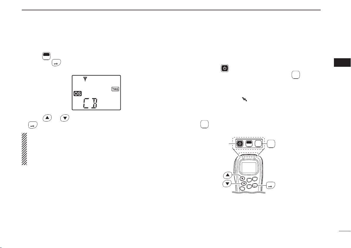
o POWER KEY (p. 14)
Push and hold for 2 sec. to turn the power ON and OFF.
!0 FUNCTION/SET KEY
SET
F
N (Function/Set Mode)
➥ Push to turn Function mode ON.
• “F” appears when Function mode is turned ON.
➥ Push and hold for 2 sec. to enter Set mode. (pgs. 19,
40)
F
(Function/RX VFO)
➥ Push to turn the Function mode OFF.
• “F” disappears when Function mode is turned OFF.
➥ Push and hold for 2 sec. to enter RX VFO mode.
(‘RX-XX’ displays while RX channel is selected) (p. 35)
NOTE: Returns to the Normal mode automatically
after 30 sec. when no key operation is performed in
Function or Set mode.
!1 MONI/T SQL KEY
MONI
TSQL
N (Monitor/TSQL)
➥ Push to toggle the monitor function ON or OFF. (p. 18)
➥ Push and hold for 2 sec. to activate the following func-
tions in order.
• Subaudible tone encoder and Tone squelch/DTCS
squelch (“TSQL” appears). (p. 27)
• Pocket beep (“TSQL ë” appears). (p. 28)
• No tone operation (“TSQL ë” disappears).
F
(SQL/ATS)
➥
Push to enter the squelch level setting mode, then
push
or to set the squelch level. (p. 18)
➥ Push and hold for 2 sec. to turn the ATS (automatic
transponder system) function ON or OFF. (p. 34)
2
9
Page 14
PANEL DESCRIPTION
2
10
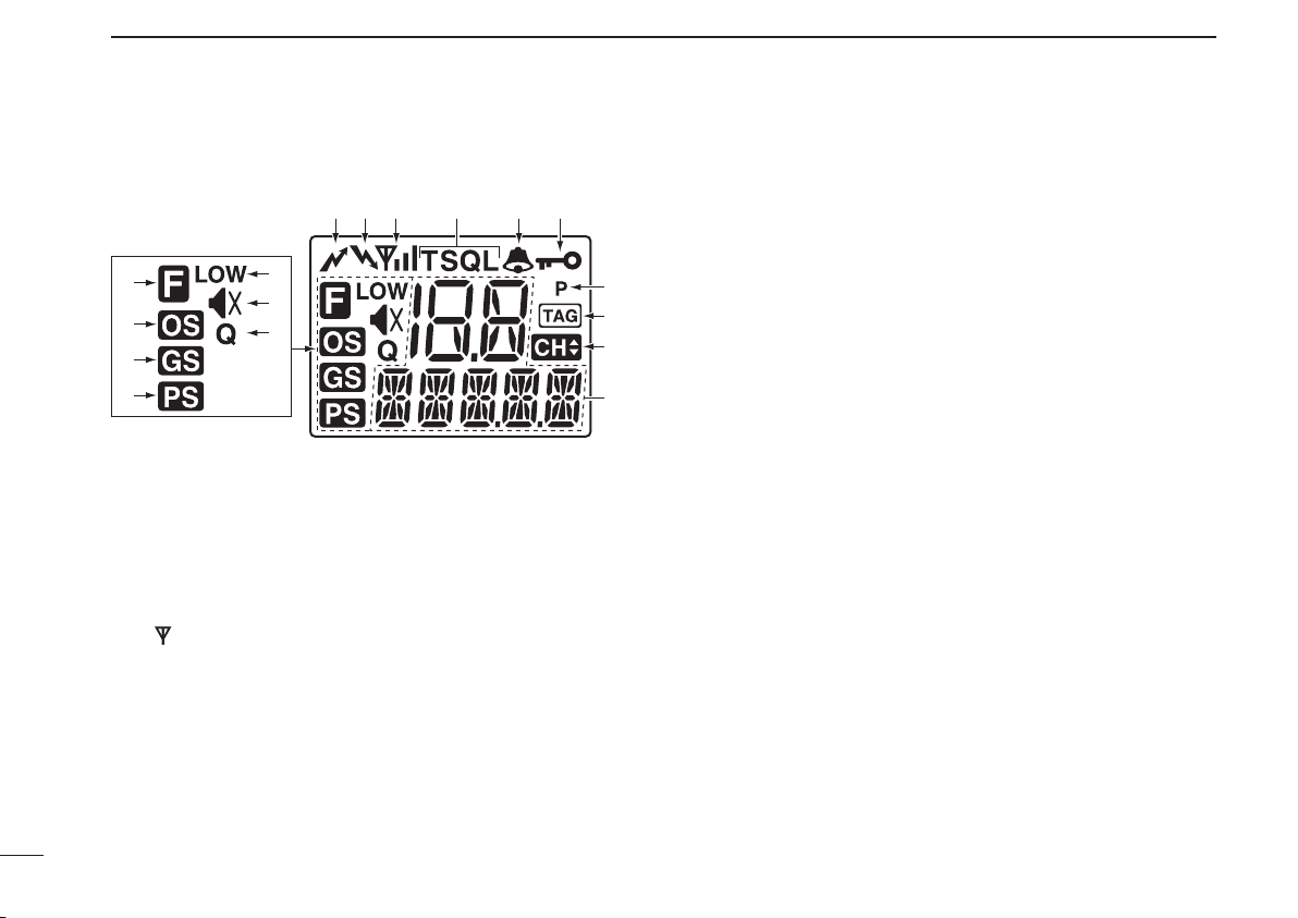
■ Function display
qw r
!4
!5
!6
!3
!7
!2
!1
q TRANSMIT INDICATOR
Appears while transmitting.
w BUSY INDICATOR
Appears while the channel is busy.
e SIGNAL STRENGTH INDICATOR
Indicates relative signal strength level.
• “ ” blinks when the ATS function is in use. (p. 34)
r TONE INDICATORS (p. 27)
➥
“T” appears while the Subaudible tone encoder is in use.
➥ “T SQL” appears while the Tone squelch/DTCS squelch
function is in use.
t BELL INDICATOR
➥
Appears when the pocket beep function is in use. (p. 28)
➥ Blinks when the specifi ed SelCall or Smart Ring call is
received. (pgs. 32, 34)
yet
u
i
o
!0
y KEY LOCK INDICATOR (p. 18)
Appears when the key lock function is selected.
u PRIORITY CHANNEL INDICATOR (p. 24)
Appears when the priority channel is set.
i TAG CHANNEL INDICATOR (p. 22)
Appears when the tag channel is selected.
o CHANNEL INDICATOR (p. 14)
Appears when channel selection mode is set.
!0 ALPHANUMERIC DISPLAY
The operating channel number, channel name, Set mode
contents etc. is displayed.
!1 PRIORITY SCAN INDICATOR (p. 24)
Appears when the ‘Priority scan’ is selected.
!2 GROUP SCAN INDICATOR (p. 24)
Appears when the ‘Group scan’ is selected.
!3 OPEN SCAN INDICATOR (p. 23)
Appears when the ‘Open scan’ is selected.
!4 FUNCTION INDICATOR
Appears when the Function mode is ON.
• A secondary function of the key can be access.
!5 LOW POWER INDICATOR (p. 15)
Appears when low output power is selected.
Page 15

!6 INTERNAL SPEAKER MUTE INDICATOR (p. 14)
Appears* when the volume level is set to 0 (the audio is
muted).
*Depending on pre-setting.
!7 QUIET INDICATOR (p. 33)
Appears when the Quiet function is ON (SelCall mute is
activated).
Information:
“N/A” appears when the pushed key is not available.
PANEL DESCRIPTION
2
2
11
Page 16

PANEL DESCRIPTION
2
■ Programmable function keys
MONI
The following functions can be assigned to
PRIO
OGP
CH
,
SETP
,
SQL
RS
optional CS-440
LOW
and
programmable function keys with the
CLONING SOFTWARE.
The key function activates after pushing
F
SET
F
when the pro-
SET
grammable function key is assigned to the function mode
operation.
If the programmable function names are bracketed in the following explanations, the specifi c key is used to activate the
function depends on the programming.
Scan/Scan Tag
➥ Push to start/stop the scan.
➥ Push and hold for 2 sec. to set or clear the displayed
channel as a TAG channel.
Scan Mode/Rpt Scan
➥ Push to select the scan mode.
➥ Push and hold for 2 sec. to start repeater scan.
PRIO/PRIO Set
➥ Push to select the priority channel.
➥ Push and hold for 2 sec. to set the displayed channel as
the priority channel.
SCAN
,
,
TAG
TSQL
S-Ring/PRIO Clear
➥ Push to transmit the Smart-Ring call.
• When RX channel is selected, “N/A” appears.
,
➥ Push and hold for 2 sec. to cancel the priority channel set-
ting.
Monitor/TSQL
(This key function can be assigned in the Normal mode only.)
➥ Push to toggle the monitor function ON or OFF.
➥ Push and hold for 2 sec. to activate the following functions
in order.
• Subaudible tone encoder and Tone squelch/DTCS squelch
• Pocket beep
• No tone operation.
RF Power/Lock
➥ Push to toggle the transmit output power level.
➥ Push and hold for 2 sec. to toggle key lock function ON
and OFF.
TX Code CH/Call
➥ Push to enter the TX code channel selection mode, then
push
or to select the desired channel (CB chan-
nel operation only).
➥ Push and hold for 2 sec. to transmit the specifi ed SelCall
TX code on the selected channel (CB channel operation
only).
12
Page 17
PANEL DESCRIPTION
2
Quiet/ID-MR
➥ Push to select function ON or OFF (CB channel operation
only).
➥ Push and hold for 2 sec. to enter the received ID code his-
tory indication mode.
SQL/ATS
➥ Push to enter the squelch level setting mode, then push
or to set the squelch level.
➥ Push and hold for 2 sec. to turn the ATS (Automatic Tran-
sponder System) function ON and OFF.
Dup/Zone
➥ Push to set the selected channel as Duplex or Simplex
operation (Depending on pre-setting).
• Duplex channel can be selected in ‘CB-R1’ to ‘CB-R8’ only.
➥ Push and hold this key for 2 sec. then push or to
select the desired zone. (Available only when more than
two zones are set.)
Function/Set Mode
(This key function can be assigned to the
F
key only.)
SET
➥ Push to turn Function mode ON or OFF.
➥ Push and hold for 2 sec. to the Set mode ON or OFF.
•
After entering the Set mode, push this key momentarily to select
the item, and push
or to change the setting.
Function/RX VFO
F
(This key function can be assigned to the
key only.)
SET
➥ Push to turn Function mode ON or OFF.
➥ Push and hold for 2 sec. to enter the RX VFO mode.
In RX VFO mode, the operating frequency and the chan-
nel spacing setting can be changed.
SQL/Set Mode
(This key function can be assigned to the
F
key only.)
SET
➥ Push to enter the squelch level setting mode, then push
or to set the squelch level.
➥ Push and hold for 2 sec. to the Set mode ON or OFF.
•
After entering the Set mode, push this key momentarily to select
the item, and push
or to change the setting.
2
13
Page 18
3
BASIC OPERATION
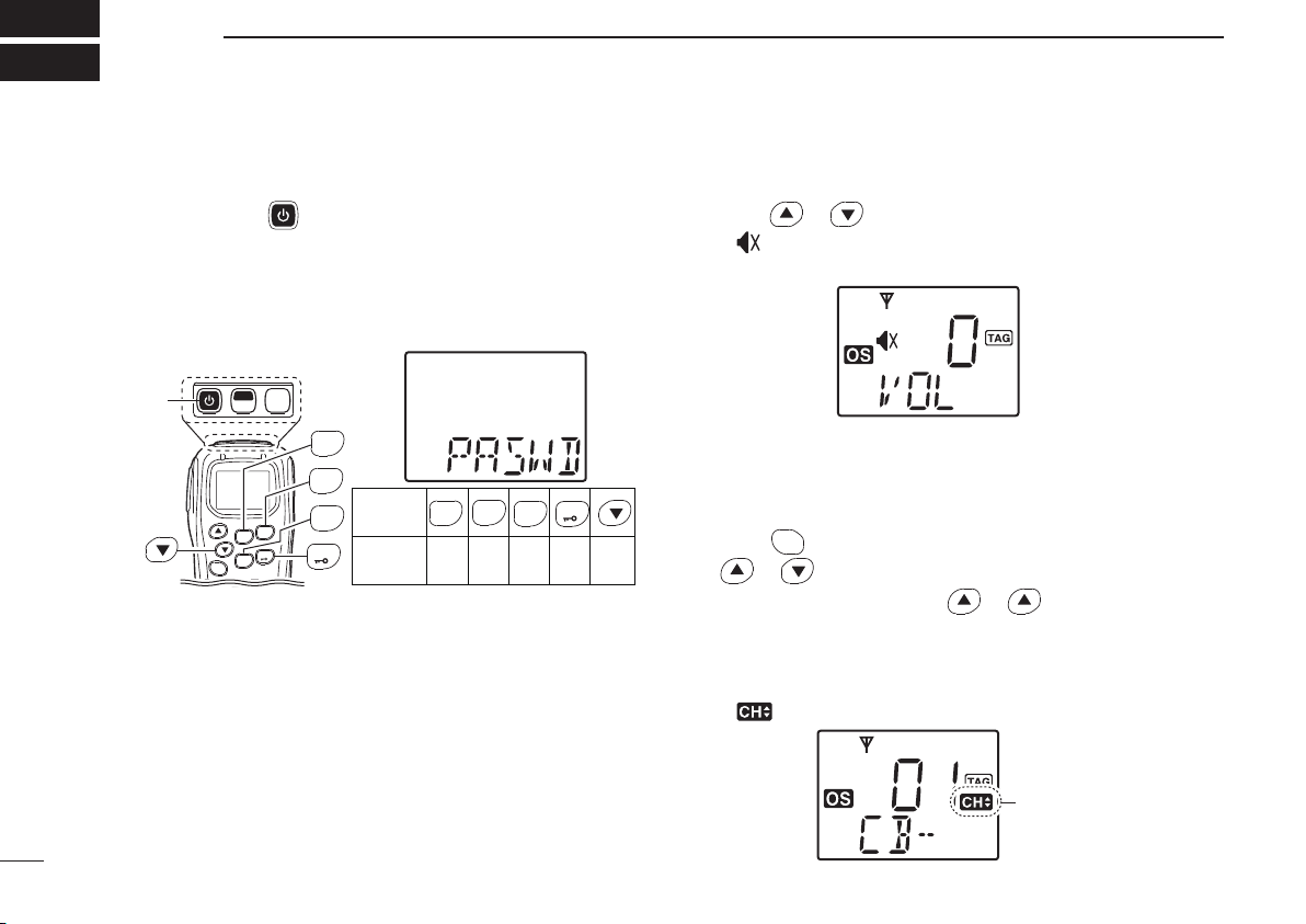
■ Turning power ON
q Push and hold for 2 sec. to turn the power ON.
w If the transceiver is programmed for a start up password,
input the digit codes as directed by your dealer.
• The keys in the table below can be used for password input:
• The transceiver detects numbers in the same block, as identical. Therefore “01234” and “56789” are the same.
MONI
[PWR]
e When the “PASWD” indication does not clear after input-
ting 4 digits, the input code number may be incorrect. Turn
the power off and start over in this case.
F
TSQL
SET
SCAN
TAG
PRIO
SETP
KEY
SCAN
TAG
0
5
OGP
RS
PRIO
SCAN
SETP
TAG
OGP
RS
CH
SQL
LOW
LOW
NUMBER
OGP
RS
PRIO
LOW
SETP
4
3
2
1
9
8
7
6
■ Volume selection
➥
Push or to select the desired volume level.
• “ ” appears
when volume level 0 is selected (while the internal
speaker is muted).
■ Channel selection
➥
•
• When channel 1 is selected, beeps are emitted.
• ‘CB-XX’ appears when the CB channel is selected and ‘RX-XX’
• “
CH
Push
to enter the channel selection mode, then push
SQL
or to select the desired channel.
While pushing and holding or , the displayed channel
changes continuously until channel 1 is selected.
appears when the RX channel is selected.
” appears when channel selection mode is selected.
14
Appears
Page 19
BASIC OPERATION
3
D Zone type selection
(Available only when more than two zones are set.)
F
Push
q
and hold
mode.
w Push or to select the desired zone, then push
LOW
NOTE:
‘CB-05,’ ‘CB-R5’ and ‘CB-35’ channels are used for the
emergency. And ‘CB-22’ and ‘CB-23’ channels are used for
telemetry and telecommand applications, so voice communications are not available on these channels.
(Function) to enter the function mode, and push
SET
LOW
(Zone) for 2 sec. to enter the zone select
(Zone) again to set.
■ Receiving and transmitting
Receiving:
q Push and hold
• If “T SQL” appears on the display, push and hold
once or twice to cancel the tone squelch or pocket beep. (pgs.
27, 28)
w Select the desired operating channel (p. 14).
• When receiving a signal, “ ” appears and audio is emitted from
the speaker.
• Further adjustment of volume level may be necessary at this
point. (p. 7)
• Push
MONI
to toggle the monitor function ON and OFF.
TSQL
for 2 sec. to turn the power ON.
MONI
[PWR]
F
SET
SCAN
TAG
OGP
RS
CH
SQL
MONI
TSQL
TSQL
PRIO
SETP
LOW
LOW
MONI
for 2 sec.
TSQL
3
15
Page 20
BASIC OPERATION
3
■ Receiving and transmitting (Continued)
Transmitting:
Wait for the channel to become clear to avoid interference.
q While pushing and holding [PTT], speak into the micro-
phone at a normal voice level.
• “ ” appears.
• A PTT hold function is available. See p. 38 for details.
w Release [PTT] to return to receive.
e Push
LOW
(RF Power) to select the output power if neces-
sary.
• “LOW” appears when low power is selected.
[PTT]
PRIO
SCAN
SETP
TAG
LOW
OGP
RS
CH
SQL
IMPORTANT: To maximize the readability of your signal;
1. Pause briefl y after pushing [PTT].
2. Hold the microphone 5 to 10 cm from your lips, then
speak into the microphone at a normal voice level.
D Transmitting notes
• Transmit inhibit function
The transceiver has several inhibit functions which restrict
transmission under the following conditions:
- The channel is busy or un-matched CTCSS/DTCS is received. (Depending on the transmission lockout function
setting.)
- The selected channel is a ‘receive only’ channel.
• Time-out timer
After continuous transmission for the pre-programmed time
period, the time-out timer is activated, causing the transceiver to stop transmitting.
16
Page 21

BASIC OPERATION
3
■ Priority channel setting
The priority channel, simply recalled by pushing
and also is automatically monitored during the priority scan.
You can set the only one channel as the priority channel.
“P” appears when the priority channel is set.
D The priority channel selection
➥ Push
• “N/A” appears when the priority channel is not set.
PRIO
SETP
(PRIO) to select the priority channel.
The priority channel
is selected.
When the priority
channel is not set.
PRIO
SETP
(PRIO),
D Set the priority channel
q Select the desired channel. (p. 14)
w Push and hold
played channel as the priority channel.
• “P” appears.
PRIO
(PRIO Set) for 2 sec. to set the dis-
SETP
“P” appears
The selected channel is set
to the priority channel.
D Cancel the priority channel setting
➥
• “P” disappears.
F
Push
and hold
(Function) to enter the function mode, then push
SET
PRIO
(PRIO Clear) for 2 sec. to cancel the priority
SETP
channel setting.
3
The priority channel
is cancelled.
17
Page 22

BASIC OPERATION
3
■ Monitor function
This function is used to listen to weak signal or to open the
tone squelch manually.
➥ Push
MONI
(Monitor) to toggle the monitor function ON and
TSQL
OFF.
• “ ” blinks when the monitor function is in use.
Blinks Blinks
■ Lock function
This function electronically locks all keys except for [PTT],
MONI
(Monitor),
TSQL
and
LOW
F
(Function),
SET
(Lock) to prevent accidental channel changes and
function access.
➥ Push and hold
LOW
function ON and OFF.
• “ ” appears when the lock function is in use.
SCAN
(Call), (Loud), (Small)
TAG
(Lock) for 2 sec. to toggle the lock
Appears
■ Adjusting the squelch level
In order to receive signals properly, the squelch must be adjusted to the proper level.
q
Push and hold
level setting mode.
➥
Push
to enter the squelch level setting mode.
w Push or to adjust the squelch level within 0 to 9
ranges.
e Push
CH
SQL
CH
(SQL) for 2 sec. to enter the squelch
SQL
F
, then push and hold
SET
CH
(SQL) also available
SQL
(SQL) to exit the squelch level setting mode.
The squelch level
is indicated.
18
Page 23

BASIC OPERATION
3
■ Display backlighting
[
The transceiver has display backlight for night-time operation.
q Push and hold
w Push
SET
F
e Push
• ON : Backlight lights continuously.
• A2 : Lights for 5 sec. when any key except [PTT] is pushed, or
the LCD indication is changed.
• At : Lights for 5 sec. when any key except [PTT] is pushed or
the Selcall signal is transmitted/received.
• OF : Backlight never lights.
F
(Set Mode) for 2 sec. to enter set mode.
SET
MONI
* or
* several times until “LIGHT” appears.
TSQL
or to select the display backlight condition.
r Push and hold for 2 sec. to turn the power OFF, or
F
push and hold
*Regardless of the assigned key function.
(Set Mode) for 2 sec. to exit set mode.
SET
■ Set mode
All set mode items are available at power ON and allows you
to set seldom-changed settings. In this case you can “customize” the transceiver operation to suit your preferences
and operating style. See p. 40 for set mode items detail.
Entering the set mode:
q While pushing and holding
for 2 sec. to turn the power ON. Then, push and hold
F
(Set Mode) for 2 sec. to enter the all set mode.
SET
w Push
SET
MONI
F
* or
* several times to select the appropriate
TSQL
item.
Then push
• Available all set mode functions are SQL Level, CTCSS
tone/ DTCS code, Auto Power OFF, Backlight, Brightness,
Contrast, Beep, Beep Level, Mic Gain, Signal Message,
Time-Out Timer (TOT), Lock-Out, Scan Stop Timer, Scan
Restart, Roger Beep, PTT Hold, Speaker and Own ID.
or to set the desired level/condition.
e Push and hold for 2 sec. to turn the power OFF, or
F
push and hold
(Set Mode) for 2 sec. to exit set mode.
SET
NOTE: Set mode can be accessed via the
key operation only (p. 40). In this case, set mode allows
quicker item selection. Only the default “Enable” items
are selectable when Set mode is activaed in the way. The
CS-440
*Regardless of the assigned key function.
CLONING SOFTWARE allows these to be modifi ed.
and , push and hold
F
(Set Mode)
SET
3
19
Page 24

4
REPEATER OPERATION
■ Repeater operation
Repeaters allow you to extend the operational range of your
radio.
Normally, a repeater has independent frequencies for receive and transmit.
Repeater
CB-R1CB-R1
Uplink
(transmitting freq.)
Downlink
(receiving freq.)
Station BStation A
■ Accessing a repeater
A repeater amplifi es received signals and re-transmits them
on a different frequency, allowing you to communicate over
greater distances with improved reliability. When using a
repeater, the repeater output channel (‘CB-R1’ to ‘CB-R8’)
must be selected.
You can search the accessible repeater in your local area
using the Repeater search scan function. (p. 25)
q Select the desired repeater output channel (‘CB-R1’ to
‘CB-R8’). (p. 14)
w While pushing and holding [PTT], speak into the micro-
phone at your normal voice level.
• “ ” appears.
Appears
e Release [PTT] to receive.
NOTE: Excludes Emergency Repeater ‘CB-R5.’
20
Page 25

SCAN OPERATION
5
■ Scan types
The transceiver has 4 scan types, tag function and 4 resume
conditions providing scanning versatility.
OPEN SCAN
ch 1 ch 2 ch 3
ch 40
ch 6ch 39
Repeatedly scans all tag channels in sequence.
GROUP OR PRIORITY SCAN
ch 2 ch 3 ch 4
ch 1
ch 10
ch 9 ch 8 ch 7
Priority
channel
Repeatedly watches a designated priority channel
after scanning 5 tagged channels.
ch 4
ch 5
ch 5
ch 6
Tag channels are independently set for open, group and priority scans. Initially, all channels may be set as tag channels
for all scans.
REPEATER SEARCH SCAN
Scan cancel
CB-R8
CB-R2CB-R1
CB-R3CB-R4
CB-R8
CB-R1
CB-R2
Scans all repeater channels (‘CB-R1’ to ‘CB-R8’)* in
sequence. If there are no busy channels after scanning
channels ‘CB-R1’ to ‘CB-R8,’* it begins scanning from
‘CB-R1’ again, then the transceiver transmits a signal to
search for a repeater while scanning.
* Excludes Emergency Repeater ‘CB-R5.’
4
5
21
Page 26

SCAN OPERATION
5
■ Scanning preparation
IC-440 scans all tagged channels, when a scan is initiated.
When the IC-440 fi nds a busy channel it can be set to pause
or resume after a pause (Scan Stop Timer). (Excluding repeater search scan).
(See Scan Stop Timer in Set mode. The default setting is
P5).
D Scan type selection
➥ Push
• Open, group and priority scans are available.
• “ ”, “ ” or “ ” is displayed for 0.5 sec. when each scan type
OGP
RS
scan type.
is selected.
Push
(Scan Mode) several times to select the desired
Appears
Open scan is selected.
OGP
Push
RS
OGP
RS
Appears
Group scan is selected.
OGP
Push
RS
Appears
Priority scan is selected.
D Tag channel setting
q Select the desired scan type. (See at left.)
w Select the desired channel. (p. 14)
e Push and hold
channel setting ON and OFF.
• “ ” appears when the tag setting is ON (The channel is set as
a scan channel).
Appears
To speed up scanning:
For open scan, cancel the tag channel setting to skip un-
desired channels such as usually busy channels.
For group scan, set only often-used channels as tag
channels.
All memory channels may be set as tag channels by de-
fault.
SCAN
TAG
(Scan Tag) for 2 sec. to toggle the tag
22
Page 27

SCAN OPERATION
5
D Setting scan resume condition
q Push and hold
w Push
SET
F
e Push
F
(Set Mode) for 2 sec. to enter set mode.
SET
MONI
* or
* several times until “SCN-T” appears.
TSQL
or to select the scan resume timer.
[
• 5 : Scan pauses for 5 sec. then resumes.
• 10 : Scan pauses for 10 sec. then resumes.
• 15 : Scan pauses for 15 sec. then resumes.
• P5 : Scan pauses until the signal disappears, then re-
sumes 5 sec. after the signal disappears.
( P5 is recommended for typical use and is the de-
fault setting).
r Push and hold
push and hold
*Regardless of the assigned key function.
for 2 sec. to turn the power OFF, or
F
(Set Mode) for 2 sec. to exit set mode.
SET
■ Open scan
Open scan searches for transmitted signals automatically
and makes it easier to locate new stations for contact or listening purposes.
IMPORTANT!:
Open scan can transmit on a start channel or busy channel.
OGP
q Push
scan. (p. 22)
• “ ” appears.
w Push
e
When receiving a signal, scan pauses and resumes according to the selected scan resume condition. (see left column)
r Push
(Scan Mode) several times to select the open
RS
Appears
Open scan is selected.
SCAN
(Scan) to start the open scan.
TAG
Blinks
Scan start channel
SCAN
(Scan) to cancel the scan.
TAG
5
23
Page 28

SCAN OPERATION
5
24
■ Group and priority scans
Group and priority scans repeatedly watch a priority channel while scanning specified channels. This is useful when
waiting for a call on the priority channel or several specified
channels.
Group and priority scans behave differently when transmitting. Group scan can transmit on a priority channel or busy
channel, and priority scan can only transmit on a priority
channel.
q Push
• “ ” appears when the group scan is selected, and “ ” ap-
w Set the priority channel if desired when the priority scan
• When the priority channel is not set, scan start channel is moni-
OGP
(Scan Mode) several times to select the group or
RS
priority scan. (p. 22)
pears when the priority scan is selected.
Appears
Group scan is selected.
Priority scan is selected.
type is selected in step q. (p. 17)
tored during the priority scan.
Appears
Appears
e Push
SCAN
(Scan) to start the scan.
TAG
Group scan starts.
Priority scan starts.
Blinks
Scan start channel
Blinks
Priority channel
r When receiving a signal, the scan pauses and resumes
according to the selected scan resume condition. (p. 23)
SCAN
t Push
(Scan) to cancel the scan.
TAG
Page 29

SCAN OPERATION
5
■ Repeater search scan
The repeater search scan not only searches for a signal on
the repeater channels, but also access a repeater by transmitting automatically in sequence.
Thus the repeater search scan function searches for available
repeater in the area even if the repeater is not currently in use.
The repeater search scan detects a signal on the re-
peater output channels (CB-R1 to CB-R8)* only. Therefore, repeater availability cannot be guaranteed even the
repeater scan is stopped, because the scan will stop if
any activity is detected. (The scan is cancelled when receiving a signal, such as stations communicating in simplex operation on a repeater output channel.)
*Excludes Emergency Repeater ‘CB-R5.’
q Select the desired repeater output channel (‘CB-R1’ to
‘CB-R8’), and push and hold
start the repeater search scan.
•
See the fl ow as described at right for repeater search scan details.
w
When receiving a signal on the repeater channel, scan stops.
•
During second cycle scanning, 3 high beeps sound when receiving
a signal, and 3 low beeps sound when no signal is received.
e Push
• During transmitting, the repeater scan cannot be cancelled.
OGP
(Scan Mode) to cancel the scan manually.
RS
OGP
(Rpt Scan) for 2 sec. to
RS
D Repeater search scan flow
Scan start
channel
Appears
Appears
Scan is cancelled automatically.
NOTE: Excludes Emergency Repeater ‘CB-R5.’
Scan
Scan
Searches for signal on the repeater
output channels.
Access to the repeater
automatically. (0.5 sec.)
Wait for a signal from
the repeater. (0.5 sec.)
(When no reply signal is received.)
Access the next repeater
automatically.
5
25
Page 30

6
TONE SQUELCH OPERATION
■ Tone squelch operation
The transceiver is equipped with 51 CTCSS tone frequencies,
104 DTCS codes. CTCSS/DTCS operation provides communication with silent standby since you will only receive calls
from group members using the same CTCSS tone frequency/
DTCS code.
NOTE: Channels 5 and 35 are used for the emergency
channels, and CTCSS/DTCS operation is not available on
these channels.
D Setting CTCSS tone frequency/
DTCS code
q Select the desired channel except for channels 5 and 35.
(p. 14)
w Push and hold
e Push
r Push
F
SET
SCAN
TAG
code setting mode.
t Push
quency/DTCS code.
y Push and hold
push and hold
F
(Set Mode) for 2 sec. to enter set mode.
SET
MONI
* or
* several times until “C” appears.
TSQL
*
to toggle the CTCSS tone frequency/DTCS
or to set the desired CTCSS tone fre-
for 2 sec. to turn the power OFF, or
F
(Set Mode) for 2 sec. to exit set mode.
SET
[
CTCSS tone setting mode
DTCS code setting mode
List number (grey line) List number (grey line)
CTCSS tone freqnency
DTCS code
• Available CTCSS tone frequency list (Hz)
Freq.
No.
01
02
03
04
05
06
07
08
09
10
11
67.0
69.3
71.0
71.9
74.4
77.0
79.7
82.5
85.4
88.5
91.5
No.
12
13
14
15
16
17
18
19
20
21
22
Freq.
94.8
97.4
100.0
103.5
107.2
110.9
114.8
118.8
123.0
127.3
131.8
No.
23
24
25
26
27
28
29
30
31
32
33
Freq.
136.5
141.3
146.2
151.4
156.7
159.8
162.2
165.5
167.9
171.3
173.8
No.
34
35
36
37
38
39
40
41
42
43
44
Freq.
177.3
179.9
183.5
186.2
189.9
192.8
196.6
199.5
203.5
206.5
210.7
No.
45
46
47
48
49
50
51
Freq.
218.1
225.7
229.1
233.6
241.8
250.3
254.1
NOTE: The transceiver has 51 tone frequencies and con-
sequently their spacing is narrow compared with units
having 38 tones. Therefore, some tone frequencies may
receive interference from adjacent tone frequencies.
26
*Regardless of the assigned key function.
Page 31

TONE SQUELCH OPERATION
6
• Available DTCS code list
Code
No.
01
02
03
04
05
06
07
08
09
10
11
12
13
14
15
16
17
18
19
20
21
023
025
026
031
032
036
043
047
051
053
054
065
071
072
073
074
114
115
116
122
125
No.
22
23
24
25
26
27
28
29
30
31
32
33
34
35
36
37
38
39
40
41
42
Code
131
132
134
143
145
152
155
156
162
165
172
174
205
212
223
225
226
243
244
245
246
No.
43
44
45
46
47
48
49
50
51
52
53
54
55
56
57
58
59
60
61
62
63
Code
251
252
255
261
263
265
266
271
274
306
311
315
325
331
332
343
346
351
356
364
365
No.
64
65
66
67
68
69
70
71
72
73
74
75
76
77
78
79
80
81
82
83
84
Code
371
411
412
413
423
431
432
445
446
452
454
455
462
464
465
466
503
506
516
523
526
No.
85
86
87
88
89
90
91
92
93
94
95
96
97
98
99
100
101
102
103
104
Code
532
546
565
606
612
624
627
631
632
654
662
664
703
712
723
731
732
734
743
754
D Turning ON the tone squelch operation
q Select the desired channel except for channels 5 and 35.
(p. 14)
w Set the desired CTCSS tone frequency/DTCS code in set
mode. (See at left page)
e Push and hold
“TSQL” appears.
r When the received signal includes a matching tone or
code, squelch opens and the signal can be heard.
• When the received signal is not matched, tone squelch
does not open, however, “
• To open the squelch manually, push
t Operate the transceiver in the normal way.
y To cancel the tone squelch operation, push and hold
(TSQL) for 2 sec. several times until “TSQL” disappears.
NOTE: CTCSS tone frequency/DTCS code and tone
squelch ON/OFF settings are automatically stored in
memory channels for easy recall.
MONI
(TSQL) for 2 sec. several times until
TSQL
” appears.
MONI
TSQL
.
Appears
MONI
TSQL
6
27
Page 32

TONE SQUELCH OPERATION
6
■ Pocket beep operation
This function uses CTCSS (subaudible) tones and DTCS
code for calling and can be used as a “common pager” to inform you that someone has called while you were away from
the transceiver.
D Waiting for a call from a specifi c station
q Select the desired channel except for channels 5 and 35.
(p. 14)
w Set the desired CTCSS tone/DTCS code in set mode.
(pgs. 26, 41)
e Push and hold
“TSQL ë” appears to activate the pocket beep.
r When the received signal includes a matching tone or
code, the transceiver emits beep tones every 10 sec. and
“ ë” blinks.
MONI
(TSQL) for 2 sec. several times until
TSQL
Blinks
28
t Push [PTT] to answer and to stop blinking.
• Tone squelch is automatically selected.
Page 33

SELCALL OPERATION
7
■ General
In addition to the tone squelch operation for silent stand-by,
the SelCall operation is available. SelCall is an abbreviation for “Selective Calling.” In tone squelch operation, there
are 155 ways to make an individual call with CTCSS tone
frequencies/DTCS codes versus 100,000 ways to make an
individual call with SelCall using 5-tone.
SelCall allows you to selectively call another unit that is operating on the same channel.
SelCall can also call the entire group on that channel using
tone squelch code.
The caller station code/name, Answer Back function, etc. are
available with SelCall operation. A variety of functions are
available depending on the setting with the CS-440
SOFTWARE. See the help fi le for setting details.
NOTE:
•
Channels 5 and 35 are used for the emergency channels,
and SelCall operation is not available on these channels.
• SelCall transmission is restricted for total of 3 sec. in a
minute. If your try to transmit over 3 sec., “N/A” appears
(when
(when [PTT] is pushed.)
SCAN
(Call) is pushed,) or error beep is emitted
TAG
CLONING
■ Calling operation
D TX code channel selection
SCAN
(TX Code CH) enables you to change the TX code
TAG
channel with
TX code means the Transmitting SelCall code. Max. 32
TX code channels can be pre-programmed into the transceiver using the optional CS-440
q Select the desired CB channel (‘CB-XX’) except for chan-
nels 5 and 35. (p. 14)
w Push
SCAN
TAG
(TX Code CH) to enter the TX code channel selection
mode.
• The channel name is displayed instead of the TX code, if the
channel name is programmed.
or .
CLONING SOFTWARE.
F
(Function) to enter the function mode, then push
SET
TX code
6
7
29
Page 34

SELCALL OPERATION
7
e Push or to select the desired TX code channel.
r Push [PTT] to transmit to the selected TX code channel,
or push
SCAN
(TX Code CH) to set the selected TX code
TAG
channel and repeat q–e, then push [PTT] to transmit.
Appears
Transmitting
✓ CONVENIENT!
The TX code channel name can be assigned to the all 32 TX
code channel via the optional CS-440
CLONING SOFTWARE.
The TX code channel name allows you to easy to select the
channel, fi nd the channel user, and so on.
D TX code number edit
SCAN
TAG
(TX Code CH) enables you to change the TX code con-
tents within the allowable digits.
The group call function works by allowing you to edit a special ‘group code’ of the SelCall ID code.
q Select the desired CB channel (‘CB-XX’) except for chan-
nels 5 and 35. (p. 14)
F
w Push
SCAN
TAG
mode.
• Push or to select the desired TX code channel, if desired.
e Push and hold
the TX code edit mode.
r Push
edited.
(Function) to enter the function mode, then push
SET
(TX Code CH) to enter the TX code channel selection
SCAN
(TX Code CH) for 2 sec. again to enter
TAG
The editable digit starts blinking
SCAN
(TX Code CH) to select the desired digit to be
TAG
30
Page 35

SELCALL OPERATION
7
t Push or to set the desired code.
• Select “À” when group code is set.
SCAN
y Push
(TX Code CH) to set the digit and the editable
TAG
digit move to right automatically.
u Repeat step t and y to input all allowed digits.
SCAN
i After setting the last digit, push
(TX Code CH) to set the
TAG
code and return to the TX code channel selection mode.
o Push [PTT] to transmit to the selected TX code channel,
or push
SCAN
(TX Code CH) to set the selected TX code
TAG
channel and return to the stand-by mode.
Appears
Transmitting
NOTE: The TX code editable digit can only be set/
changed with the optional CS-440
CLONING SOFTWARE.
✓ CONVENIENT!
F
Push
and hold
(Function) to enter the function mode, then push
SET
SCAN
(Call) for 2 sec. to transmit the selected chan-
TAG
nel’s TX code easily.
Appears
7
Transmitting
31
Page 36

SELCALL OPERATION
7
32
■ When receiving a call
D Receiving an individual call
q When receiving a RX code (default setting);
• “PiRo” beeps sound.
• The received code channel name is displayed, if programmed.
• “ë” and the displayed channel name* blink, and the SelCall
mute is released when the quiet mode is activated.
* “ë” and the channel number blink when the channel name is
not programmed.
w While pushing and holding [PTT], speak into the micro-
phone at a normal voice level.
Blink
NOTE: When the ID decode function is turned ON, the re-
ceived ID code is displayed instead of the channel name, and
memorised into the transceiver. The ID decode function can
be turned ON using the optional CS-440 CLONING SOFTWARE.
• RX code means the Receiving SelCall code. Max. 8 in-
dividual call channels can be pre-programmed into the
transceiver using the CS-440.
• You can set the transceiver’s condition when receiving
an individual call using the CS-440. See the help fi le for
setting details.
Recall the memorised received ID code:
q Push
w
e Push [PTT] to transmit the code on the selected channel.
F
(Function) to enter the function mode, then push
SET
and hold
OGP
(ID-MR) for 2 sec. to display the memorised
RS
received ID code.
Push or to select the desired received ID code.
D Receiving a group call
q When receiving a group call (default setting);
• “PiPi” beep sounds.
• “ë” and “GROUP” blink, and the SelCall mute is released when
the quiet mode is activated.
w While pushing and holding [PTT], speak into the micro-
phone at a normal voice level if necessary.
Blink
You can set the transceiver’s condition when receiving a
group call with the CS-440. See the help file for setting
details.
Page 37

SELCALL OPERATION
7
■ Quiet mode operation
When the quiet mode operation is turned ON, the SelCall
mute is activated and allows the silent operation until receiving a SelCall.
➥ Push
• “Q” appears when the quiet mode is in use.
To monitor the channel:
➥ Push
• “ ” blinks when the monitor function is in use.
F
(Function) to enter the function mode, then push
SET
OGP
(Quiet) to toggle the quiet mode ON and OFF.
RS
Appears
MONI
(Monitor) to release the mute (audio is emitted.)
TSQL
Blinks
To enable SelCall mute:
➥ When “ ” blinks, push
” disappears.
• “
MONI
(Monitor) to mute the channel.
TSQL
NOTE: The unmute condition may automatically return to
the mute condition after a specifi ed time period depending
on the pre-setting.
■ Stun function
When the transceiver is in the Stun condition, it will request
a password at power ON. This password is the same as the
Power ON password function. Once the password has been
input, the transceiver will not prompt for it to be input again.
Cloning and use of the transceiver is disabled when the kill
ID is received. By activating the clone write condition, the
transceiver can be returned to an usable condition.
(The internal data can not be accessed by the cloning read
condition.)
7
33
Page 38

8
OTHER FUNCTIONS
■ Smart-Ring and ATS (Automatic Transponder System)
34
These functions have an answer back feature, and allow
you to confi rmation of whether or not a call has reached the
receiving party even if the operator is temporarily away from
the transceiver. The Smart-Ring is for manual, and the ATS
is for automatic confi rmation.
D Smart-Ring
q Set the same CTCSS tone frequency for all of the group
transceivers and turn the tone squelch ON. (pgs. 26, 41)
F
w Push
PRIO
SETP
• “ ” appears.
• When a member of a specific group answers a call, “ë” and
“FOUND” blink.
• When no answer back is received, the transceiver emits short
failure beep tones and “FAILD” appears.
Appears
e Push [PTT] to answer and to stop blinking.
NOTE: The Smart-Ring function is available only when the
called station has set the same CTCSS tone frequency
and the same operating channel as you.
(Function) to enter the function mode, then push
SET
(S-Ring) to send the Smart-Ring call.
Blink
NOTE:
• The setting at left is for the calling station only. A called
party automatically sends an answer back signal without any pre-settings. All IC-440’s operating on the same
operating channel will answer back to the call in the surroundings communications area.
• When RX channel is selected, “N/A” appears.
D ATS
q
• When RX channel is selected, error beep is emitted.
• The transceiver starts to send a searching signal every 60 sec.
• “ ” appears and “ ” starts blinking on the display when the
• When the transceiver receives an answer back signal, “
• If no reply is received, “
Appears
w Push
F
Push
and hold
function is activated.
on the display until the next search transmit.
Blinks
and hold
(Function) to enter the function mode, then push
SET
MONI
(ATS) for 2 sec. to turn the ATS function ON.
TSQL
” blinks until the next search transmit.
Blinks
F
(Function) to enter the function mode, then push
SET
MONI
(ATS) for 2 sec. to turn the ATS function OFF.
TSQL
” stays
Page 39

■ RX frequency setting (for RX channels only)
OTHER FUNCTIONS
8
The receive frequency in the RX channels can be re-programmed within 450 to 520 MHz frequency range depending
on the setting.
D RX channel setting
The RX channels does not appear on the LCD (default; “Inhibit” setting) and you cannot select it. So the RX channels
should be set to “Enable” before programming the RX frequency.
q While pushing and holding
SCAN
TAG
to indicate all pre-programmed RX channels (including
the inhibited channels.)
w Select the desired channel with
SCAN
*
to set the displayed channel “Enable.”
TAG
“Inhibit” setting “Enable” setting
e Turn the power OFF, then ON.
• The “Enable” channels appear on the LCD, and push
push
/ to select the desired RX channel.
LOW
*
and
*
, turn power ON
or , then push
CH
SQL
then
D RX frequency programming
q Select the desired RX channel (‘RX-XX’). (See at left)
F
w Push
and hold
mode.
• Push
(in function mode)
e Push or several times to select the desired fre-
quency.
• The frequency changes according to the Wide/Narrow setting.
(p. 37)
*Regardless of the assigned key function.
(Function) to enter the function mode, then push
SET
F
(RX VFO) for 2 sec. to enter the RX VFO
SET
LOW
*
to toggle the bandwidth between wide or narrow.
*
RX channel
Wide channel spacing
(25 kHz steps)
RX VFO mode
Narrow channel spacing
(12.5 kHz steps)
Appears when
Narrow channel
spacing is set.
8
35
Page 40

OTHER FUNCTIONS
8
SCAN
*
r Push
to select the desired digit to be edited.
TAG
u Repeat steps t and y to input the desired frequency.
36
(Wide channel spacing) (Narrow channel spacing)
t Set the desired digit via or .
(Wide channel spacing) (Narrow channel spacing)
SCAN
*
y Push
to set the digit and the editable digit move to
TAG
right automatically.
(Wide channel spacing) (Narrow channel spacing)
(Wide channel spacing) (Narrow channel spacing)
i Push and hold
F
* for 2 sec. to return to the normal op-
SET
eration condition.
• RX frequency setting is memorised to the channel.
• Pushing
In this case, the RX frequency setting is not memorised to the
channel. (temporary operation)
*Regardless of the assigned key function.
F
* also returns to the normal operation condition.
SET
Page 41

OTHER FUNCTIONS
8
■ Wide/Narrow function
This function temporarily/permanently changes the bandwidth between wide or narrow on the RX channel only.
q Select the desired RX channel. (p. 35)
w Enter the RX VFO mode. (p. 35)
e Push
LOW
*
to toggle the bandwidth between wide or nar-
row.
Wide channel spacing is selected
Narrow channel spacing is selected
r Push and hold
F
* for 2 sec. to return to the normal op-
SET
eration condition.
• The bandwidth setting is memorised to the channel.
• Pushing
this case, the bandwidth setting is not memorised to the channel. (temporary operation)
*Regardless of the assigned key function.
F
* also returns to the normal operation condition. In
SET
8
37
Page 42

OTHER FUNCTIONS
8
■ PTT hold function
[
The PTT switch can be operated as a one-touch PTT switch
(each push toggles between transmit/receive). Using this
function you can transmit without pushing and holding the
PTT switch.
To prevent accidental, continuous transmission with this
function, the time-out timer function is automatically set
within the transceiver. See pgs. 40, 45 for details.
q Push and hold
w Push
SET
F
e Push
F
(Set Mode) for 2 sec. to enter set mode.
SET
MONI
* or
* several times until “P--HLD” appears.
TSQL
or to set the PTT hold function ON or OFF.
r Push and hold for 2 sec. to turn the power OFF, or
F
push and hold
(Set Mode) for 2 sec. to exit set mode.
SET
t When the PTT hold function is set to ON, push [PTT] to
transmit and push again to receive.
• “ ” appears while transmitting.
*Regardless of the assigned key function.
■ Data cloning
Cloning allows you to quickly and easily transfer the data
from a personal computer to a transceiver using the optional
CS-440
Data can be cloning to and from a personal computer (Microsoft
bit)) using the optional CS-440
optional cloning cable OPC-1122U (USB type).
Consult the CS-440
CLONING SOFTWARE.
®
Windows® 2000/XP/Microsoft® Windows VistaTM (32
CLONING SOFTWARE and the
CLONING SOFTWARE HELP fi le for details.
to USB port
PC
OPC-1122U
(USB type)
IC-440
to the [MIC] connector
38
Page 43

■ All reset
The function display may occasionally display erroneous information. This may be caused externally by static electricity
or by other factors.
If this problem occurs, turn power OFF. After waiting a few
seconds, turn power ON again. If the problem persists, perform the following procedure.
IMPORTANT!:
Resetting the transceiver sets set mode values to default.
CH
LOW
While Pushing
SQL
,
sec. to reset the CPU.
• “AL RESET” appears on the function display when the transceiver
is reset.
and
MONI
, push and hold for 2
TSQL
OTHER FUNCTIONS
8
8
39
Page 44

9
SET MODE
■ Set mode
Set mode allows you to change seldom used common setting for the transceiver, or individual setting for the operating
channel. In this case you can “customize” transceiver operation to suit your preferences and operating style.
Available functions may differ depending on the pre-setting
via the optional CS-440
NOTE: Set mode can be accessed via the
key operation after turning power ON with
(p. 19). In this case, “all set mode” is available.
D Set mode construction
Starting item
CLONING SOFTWARE.
• CTCSS/DTCS • Auto Power OFF • Backlight • Brightness • Contrast • Beep• Squelch Level
• Scan Stop Timer
• Scan Restart
• Lock-out
• Roger Beep
F
(Set Mode)
SET
and
• Time-Out Timer
• PTT Hold
(TOT)
D Set mode operation
q
Push and hold
• When no key is pushed for 30 sec. the transceiver returns to
normal operation.
w Push
SET
F
e Push
item.
r Push and hold
push and hold
*Regardless of the assigned key function.
• Signal Message
• Speaker
F
(Set Mode) for 2 sec. to enter Set mode.
SET
MONI
* or
* to select the desired item, if necessary.
TSQL
or to select the desired condition of the
for 2 sec. to turn the power OFF, or
F
(Set Mode) for 2 sec. to exit set mode.
SET
• Mic Gain
• Own ID
• Beep level
: Push
: Push
SET
MONI
TSQL
F
40
Page 45

SET MODE
9
■ SET mode items
D Squelch level*
Select the noise squelch threshold level within the range 0 to
9.
• There are 10 squelch levels to choose from 0 is completely open; 9
is a tight squelch; 1 is a loose squelch level.
Squelch level 1 (default)
D CTCSS tone frequency/DTCS code
Select the desired CTCSS tone frequency or DTCS code.
Pushing
CTCSS tone frequency
setting mode (default)
SCAN
*
toggles the CTCSS/DTCS setting mode.
TAG
Push
Squelch level 0 (“ ”appears)
SCAN
TAG
DTCS code setting mode
D Auto Power OFF
The transceiver can be set to automatically turn OFF after a
set period has passed when no key operation is performed.
• 0.5 to 4.0 hours (0.5 hours steps) and OFF can be specifi ed.
Auto power OFF
is OFF (default)
2.0 hours setting
D LCD backlight condition
The transceiver has a LCD backlight for night-time operation.
ON : Backlight turns ON continuously.
A2
(Auto2) : Lights for 5 sec. when any key except [PTT] is
pushed, or the LCD indication is changed.
At
(Auto) : Lights for 5 sec. when any key except [PTT] is
pushed or the SelCall signal is transmitted/ received.
OF
(OFF) : No backlight available.
9
*Regardless of the assigned key function.
Backlight Auto (default) Backlight ON
41
Page 46

SET MODE
9
D LCD backlight brightness
The LCD backlight brightness can be adjusted from 0 (dark)
to 7 (bright).
Bright level 4 (default) Bright level 0
D LCD contrast
The contrast level of the LCD can be adjusted from 0 (dark)
to 7 (bright).
Contrast level 5 (default) Contrast level 0
D Beep tone
You can select silent operation by turning key-touch beep
tones OFF, or you can have confi rmation beeps sound at the
push of a key by turning beep tones ON.
Beep tone ON (default) Beep tone OFF
D Beep level
Set the key-touch beep output level HIGH or LOW.
Beep level High (default) Beep level Low
42
Page 47

SET MODE
9
D Microphone gain level
Set the microphone gain level from 1 (Min) to 5 (Max).
Mic gain level 3 (default) Mic gain level 1
D Signal message displaying function
This function display “ROGER” or “SCALL” when the roger
beep signal or selcall signal is transmitting.
It is useful to check the rogger beep function or selcall function is ON or OFF.
ON : “ROGER” or “SCALL” displays on the function
display when the roger beep signal or secall signal is transmitting.
OF
(OFF) : No message is displayed.
D Time-Out timer (TOT)
The Time-Out Timer (TOT) function limits continuous transmission to prevent accidental prolonged transmission, etc.
This timer cuts a transmission OFF after 1 min. of continuous transmission.
TOT OFF (default) TOT ON
D Lock-Out function
Select the transmission lock-out (temporary transmission inhibit) capability.
RP
(Repeater Lockout) : Transmission is permitted only while
receiving a matched CTCSS tone, or
receiving no signal.
bu
(Busy Lockout) : Transmission is inhibited while receiv-
ing a signal.
OF
(OFF) : No restriction for receiving a signal.
9
Signal messge display ON (default) Signal message display OFF
Lockout OFF (default) Repeater lockout setting
43
Page 48

SET MODE
9
D Scan resume timer
The scan resume condition can be set as a pause (P5) or
timer scan (15/10/5). When a signal disappears, scan resumes after 5 sec. has passed regardless of the setting.
15/10/5 : Scan pauses for 15, 10 or 5 sec. when a signal is
detected, then resumes after that.
P5 : Scan pauses until the signal disappears and then
resumes after 5 sec. (Default and recommended
setting).
Scan resume timer
P5 (default)
10 sec. setting
D Scan restart function
This function starts the scan after the transmission is performed during scan and 10 sec. has passed.
D Roger Beep
This function emits a beep on the communication party to
inform the transmission is fi nished.
Roger beep OFF (default) Roger beep ON
44
Scan restart timer
OFF (default)
Scan restart timer ON
Page 49

SET MODE
9
D PTT Hold function
The PTT switch can be operated as a one-touch PTT switch
(each push toggles between transmit/receive). Using this
function you can transmit without pushing and holding the
PTT switch.
To prevent accidental, continuous transmission with this
function, the time-out timer function is automatically set to
the transceiver. See p. 38 for details.
PTT hold OFF (default) PTT hold ON
D Internal speaker setting
This function sets if audio is emitted from the HM-182 or an
external speaker (if connected).
ON
(ON) : The audio from the HM-182 sounds even when
an external speaker is connected.
At (AUTO) : The audio from the HM-182 is muted then
[
] appears on the function display. (The audio
comes from the HM-182 when the external
speaker is not connected).
Internal speaker ON (default) Internal speaker Auto
9
45
Page 50

SET MODE
9
D Own ID
This function allows you to edit the Own ID.
Own ID ‘11111’
To edit the Own ID:
F
q Push and hold
F
w Push
SET
* or
e Push and hold
(Set Mode) for 2 sec. to enter Set mode.
SET
MONI
* to select the “Own ID” item.
TSQL
SCAN
*
TAG
for 2 sec. to enter the Own ID edit
mode.
r Push
t Push
or several times to select the desired digit.
SCAN
*
TAG
to set the digit and the editable digit move to
right automatically.
y Repeat steps r and t to input the desired ID code.
u After setting the last digit, push
SCAN
*
TAG
to set the Own ID
code.
46
*Regardless of the assigned key function.
Page 51

MAINTENANCE
■ Troubleshooting
If your transceiver seems to be malfunctioning, please check the following points before sending it to a service center.
10
PROBLEM
The transceiver’s power
will not turn ON.
No sound comes from the
speaker.
Sensitivity is low and only
strong signals are audible.
No contact possible with
another station.
Frequency cannot be set.
Scan does not operate.
Transmission is automatically cut off.
POSSIBLE CAUSE
• Power connector has a poor contact.
• Polarity of the power connection is reversed.
• Blown fuse.
• Volume is too low.
• The volume level is set to 0 (audio muting).
• Squelch is set too high.
• A selective call or squelch function is activated
such as pocket beep or tone squelch.
• Antenna feedline or the antenna connector has a
poor contact or is short circuited.
• The other station is using tone squelch.
• The lock function is activated.
• Priority scan is paused on the watching frequency.
• The channel selection mode is not set.
• The squelch is open.
• Priority scan is activated.
• Time-out timer function is activated.
SOLUTION
• Check the connector pins.
• Re-connect the power cable observing the proper
polarity.
• Check the cause, then replace the fuse.
• Push
• Push .
• Set the squelch level to the threshold.
• Turn the appropriate function OFF.
• Check, and if necessary, replace the feedline or
solder the antenna connector again.
• Turn the tone squelch function ON.
• Push and hold
lock function.
• Push
• Push
• Set the squelch to the threshold point.
• Cancel the scan.
• Set the timer to OFF.
.
LOW
for 2 sec. to deactivate the
SCAN
to cancel the scan.
TAG
CH
to enter the channel selection mode.
SQL
REF.
—
p. 4
p. 48
p. 14
p. 14
p. 18
pgs. 26
–28
p. 5
p. 26
p. 18
p. 24
p. 14
p. 18
p. 24
p. 43
9
10
47
Page 52

MAINTENANCE
10
PROBLEM
Transmission continues
even when the PTT is released.
The function display
shows erroneous information.
• PTT hold function is activated.
• The CPU is malfunctioning.
POSSIBLE CAUSE
■ Fuse replacement
If the fuse blows or the transceiver stops functioning, fi nd the
source of the problem if possible, and replace the damaged
fuse with a new one, rated at (FGB 5 A) as shown at right.
SOLUTION
• Turn the function OFF.
• Reset the CPU.
5 A
fuse
REF.
pgs. 38,
45
p. 39
48
Page 53

SPECIFICATIONS AND OPTIONS
11
■ Specifi cations
D GENERAL
• Frequency coverage
CB : 476.425–477.400 MHz
RX : 450.000–520.000 MHz (RX only)
• Mode : 16K0F3E
• Number of channels : Max 128ch/8 banks
• Antenna impedance : 50 Ω
• Input impedance : 600 Ω
• Output impedance : 4 Ω
• Intermediate frequency : 1st 46.35 MHz, 2nd 450 kHz
• Operating temperature range
: –10°C to +60°C
• Power supply voltage : 13.8 or 27.6 V DC nominal
(Negative ground)
• Current drain (approx.)
DC 13.8 V : RX stand-by 400 mA
RX Max. audio 1500 mA
TX (5 W) 2000 mA
DC 27.6 V : RX stand-by 250 mA
RX Max. audio 1000 mA
TX (5 W) 1200 mA
• Dimensions : 125 (W) × 25(H) × 160.7(D) mm
(Projections not included)
• Weight (approx.) : 770 g (with HM-182)
D TRANSMITTER
• Output power : 5 W/1 W (selectable)
• Modulation system :
• Max. frequency deviation : ±5 kHz
• Frequency error : ±2.5 ppm
• Spurious emissions : Less than –30 dBm
• Adjacent channel power : Less than –22 dBm
• Audio harmonic distortion : 1% typical (60% deviation)
• Residual modulation : 40 dB typical
• Limiting charact of modulator : 70 to 100% of max. deviation
Variable reactance frequency
modulation
D RECEIVER
[CB (476.425–477.400 MHz)]
• Sensitivity (12 dB SINAD) : 0.22 µV typical
• Squelch sensitivity : 0.2 µV typical (Threshold)
• Hum and noise : 50 dB typical
•
Intermodulation rejection ratio:
•
Spurious response rejection ratio
More than 65 dB (IF/2)
• Adjacent channel selectivity : 78 dB typical
•
Conducted spurious radiation
• Audio output power : 5.0 W typ. at 10% distortion with a
• Audio frequency response : +1 to –3 dB of 6dB/octave from
75 dB typical
: 80 dB typical
: Less than –57 dBm
(9 kHz–2.9 GHz)
4 Ω load
300 to 3000 Hz
10
11
49
Page 54

SPECIFICATIONS AND OPTIONS
11
■ Specifi cations (Continued)
D RECEIVER
[RX (450.000–520.000 MHz)] (Except CB (476.425–477.400 MHz))
• Sensitivity (12 dB SINAD) : 0.25 µV typical
• Hum and noise : 50 dB typical
•
Conducted spurious radiation
• Audio frequency response : +1 to –3 dB of 6dB/octave from 300
All stated specifi cations are subject to change without notice or
obligation.
: Less than –57 dBm
(9 kHz–2.9 GHz)
to 3000 Hz
■ Options
D MICROPHONE
• HM-182 HAND MICROPHONE
Wired remote control microphone with key backlight. Same as
supplied with the transceiver.
• OPC-647 EXTENSION CABLE
2.5 m microphone extension cable. Same as supplied with the
transceiver.
D SPEAKER
• SP-22 EXTERNAL SPEAKER
Compact and easy-to-install.
D CLONING SOFTWARE
• CS-440 CLONING SOFTWARE + OPC-1122U USB CLONING CABLE
Provides quick and easy programming items, such as set mode
contents, zone type, etc. via PC’s USB terminal.
50
Page 55

WARRANTY AND PRODUCT REGISTRATION
12
ICOM LIMITED WARRANTY
Icom Incorporated is proud of its advanced technology and
the high quality of workmanship and components included in
the production of every product.
Icom (Australia) Pty. Ltd., the authorised Icom Distributor,
warrants this Icom product within Australia to be free from
defects in material or workmanship for the applicable period
indicated below:
• Radios:
Three (3) years from the date of purchase, (excluding
accessories), when purchased from an Australian authorised Icom Dealer.
• Accessories:
One (1) year from the date of purchase, when purchased
from an Australian authorised Icom Dealer.
(hand microphone and external speaker)
Icom (Australia) Pty. Ltd. will, at its discretion, and subject to
the terms and conditions stated below, repair or replace any
goods (Includes supplied accessories such as the HM-182.
See “Supplied accessories” p. 1) or component parts which
after examination are found to be defective.
Unless otherwise expressly provided, any fault arising from
defective workmanship or material shall be rectifi ed by Icom
where the equipment is returned freight prepaid to Icom,
Service Dept. Unit 1/103 Garden Road, Clayton, Victoria
3168
This warranty shall not apply:
(a) To an Icom Product which has failed due to improper
installation, misuse, accident, alteration or unauthorised repair or modifi cation.
(b) If any serial number or identification plate attached to
the goods has been altered, rendered illegible, or removed
(c) If the goods have been damaged by corrosion, deterio-
ration or the like contributed to abnormal temperatures;
the infl uence of foreign matter or energy or physical or
chemical properties of water, steam or chemical compounds.
To any Icom product not originally supplied by Icom (Australia) Pty Ltd to an authorized Dealer of Icom (Australia) Pty.
Ltd.
Please check with us if you feel an Icom product is
being offered for sale that has been sourced from other
than Icom (Australia) Pty Ltd.
11
12
51
Page 56

WARRANTY AND PRODUCT REGISTRATION
12
52
WARRANTY SERVICE INSTRUCTIONS
1. If you are experiencing diffi culty with your Icom equipment return it to Icom (Australia) Pty. Ltd., preferably in
the original carton, without accessories and include a
brief explanation of the diffi culty you are experiencing.
Although we take the utmost care Icom (Australia) Pty.
Ltd. shall assume no liability for the loss or safe return
of an accessory item.
2. Include accessories only if your specific situation
indicates an accessory related difficulty exists. It is
important to itemise these accessories on the note of
explanation.
3. If the requested repairs or service are within the terms
of the warranty, your equipment will be repaired and returned prepaid to any designated point within Australia.
The freight carrier is at the option of Icom (Australia)
Pty Ltd.
4. If the requested repairs or service are not within the
terms of warranty or if you fail to provide acceptable
evidence of the date of purchase you will be contacted
with a quote to repair your equipment. Return freight
will be charged in this instance.
5. All equipment returned under warranty must be freight
prepaid. Freight collect packages will not be accepted.
The benefi ts conferred by this warranty are in addition to all
implied warranties, other rights and remedies in respect of
the product which the consumer has under the Trade Prac-
tices Act and similar State and Territory Laws.
PRODUCT REGISTRATION
Please log on to “http://www.icom.net.au/” to register your
Icom product, or complete & return the registration reply
page.
Page 57

Cut here
Unit 1/103 Garden Road
Clayton VIC 3168
Icom (Australia) Pty. Ltd.
POSTAGE
HERE
Please fold and tape closed
REGISTRATION CARD
PLACE
Page 58

Product and Owners detail
Model No:
Dealers Name:
Purchasers Name:
Purchasers Address:
Contact Phone No:Email:
Serial No:
Date of Purchase:
Occupation:
Answering the following question will better help us meet your future needs:
In what media have you seen ICOM Advertising?
Newspaper
Magazines you regularly purchase and/or subscribe to:
I would like more information on the following:
Air Band Commercial Radios
Other Radio Communications Equipment you use:
Comments:
Magazine TV Radio Website
Other:
MarineAmateur
UHF CBReceiver
Thank you for completing this Registration, we feel confident you will enjoy many years of reliable performance from your
Icom IC-440.
Cut here
Page 59

MEMO
55
Page 60

MEMO
56
Page 61

INDEX
Accessing a repeater ············································································ 20
– A –
Accessories and connection ··································································· 1
Adjusting the squelch level ··································································· 18
All reset ································································································· 39
Antenna connector ················································································· 5
Antenna installation ················································································ 5
Antenna location ····················································································· 5
ATS ······································································································· 34
Auto power OFF ··················································································· 41
– B –
Basic operation ····················································································· 14
Battery connection ·················································································· 4
Beep level ····························································································· 42
Beep tone ····························································································· 42
– C –
Calling operation ··················································································· 29
Cancel the priority channel setting ······················································· 17
Channel selection ················································································· 14
Cloning software ··················································································· 50
CTCSS tone frequency/DTCS code ····················································· 41
– D –
Data cloning ·························································································· 38
DC power supply connection ·································································· 4
Display backlighting ·············································································· 19
– E –
Explicit defi nitions ···················································································· i
Function display ···················································································· 10
– F –
Fuse replacement ················································································· 48
– G –
General ··························································································· 29, 49
Group and priority scans ······································································ 24
Group or priority scan ··········································································· 21
– H –
HM-182 front and top panels ·································································· 7
– I –
IC-440 front and rear panels ··································································· 6
Important ································································································· i
Installation ······························································································ 1
Installation methods ················································································ 2
Internal speaker setting ········································································ 43
– L –
LCD backlight condition ········································································ 41
LCD backlight brightness ······································································ 42
LCD contrast ························································································· 42
Location ·································································································· 1
Lock function ························································································ 18
Lockout function ··················································································· 44
– M –
Maintenance ························································································· 47
Microphone ··························································································· 50
Microphone connection ·········································································· 3
Microphone gain level ··········································································· 43
Microphone hanger attachment ······························································ 3
Monitor function ···················································································· 18
57
Page 62

INDEX
Open scan ······················································································ 21, 23
– O –
Operating notes ······················································································· i
Options ································································································· 50
Other functions ····················································································· 34
Own ID ·································································································· 46
– P –
Panel description ···················································································· 6
Pocket beep operation ·········································································· 28
Precautions ······························································································ii
Priority channel setting ········································································· 17
Programmable function keys ································································ 12
PTT hold function ··········································································· 38, 45
– Q –
Quiet mode operation ··········································································· 33
– R –
Receiver ······························································································· 49
Receiving a group call ·········································································· 32
Receiving an individual call ·································································· 32
Receiving and transmitting ··································································· 15
Repeater operation ··············································································· 20
Repeater search scan ···································································· 21, 25
Repeater search scan fl ow ··································································· 25
Roger Beep ·························································································· 45
RX channel setting ··············································································· 35
RX frequency programming ·································································· 35
RX frequency setting ············································································ 35
– S –
Scan operation ····················································································· 21
Scan restart function ············································································ 44
Scan resume timer ··············································································· 44
Scan type selection ·············································································· 22
Scan types ···························································································· 21
Scanning preparation ··········································································· 22
Selcall operation ··················································································· 29
Set mode ························································································ 19, 40
Set mode construction ·········································································· 40
Set mode items ····················································································· 41
Set mode operation ·············································································· 40
Set the priority channel ········································································· 17
Setting CTCSS tone frequency/DTCS code ········································· 26
Setting scan resume condition ····························································· 23
Signal message displaying function ····················································· 43
Smart-Ring ··························································································· 34
Speaker ································································································ 50
Specifi cations ······················································································· 49
Specifi cations and options ···································································· 49
Squelch level ························································································ 41
Stun function ························································································· 33
Supplied accessories·············································································· 1
– T –
Table of contents ····················································································iii
Tag channel setting ··············································································· 22
The priority channel selection ······························································· 17
Time-Out timer (TOT) ··········································································· 43
Tone squelch operation ········································································ 26
Transmitter ···························································································· 49
Transmitting notes ················································································ 16
Troubleshooting ···················································································· 47
Turning ON the tone squelch operation ················································ 27
Turning power ON ················································································· 14
TX code channel selection ··································································· 29
TX code number edit ············································································ 30
58
Page 63

INDEX
Using the mounting bracket ···································································· 2
Volume selection ·················································································· 14
Waiting for a call from a specifi c station ··············································· 28
Warranty and product registration ························································ 51
When receiving a call ··········································································· 32
Wide/Narrow function ··········································································· 37
Zone type selection ·············································································· 15
– U –
– V –
– W –
– Z –
59
Page 64

THE ICOM UHF CB TRANSCEIVER LINE UP.
The follow transceivers can also communicate with IC-440.
Ask your Icom (Australia) authorized dealer or see Icom home page
(http://www.icom.net.au/) for details.
IC-41S
(Handheld type)
A-6678D-1AU-q
Printed in Japan
© 2008 Icom Inc.
Printed on recycled paper with soy ink.
IC-400PRO
(Mobile type)
1-1-32 Kamiminami, Hirano-ku, Osaka 547-0003, Japan
 Loading...