

Page 1

INSTRUCTION MANUAL
UHF C.R.S.TRANSCEIVER
i41W
Page 2

IMPORTANT
GENERAL INFORMATION
READ ALL INSTRUCTIONS carefully before using
the IC-41W UHF C.R.S. transceiver.
KEEP THIS INSTRUCTION MANUAL, as it con-
tains important operating information that may be useful in
the future.
EXPLICIT DEFINITIONS
WORD DEFINITION
RDANGER!
RWARNING!
CAUTION
NOTE
Icom, Icom Inc. and the Icom logo are registered trademarks of Icom Incorporated (Japan) in Japan, the United States, the United Kingdom, Germany,
France, Spain, Russia and/or other countries.
i
Personal death, serious injury or an explosion may occur.
Personal injur y, fire hazard or electric
shock may occur.
Equipment damage may occur.
If disregarded, inconvenience only. No risk
of personal injury, fire or electric shock.
i. The Citizen Band Radio Service is licensed in Australia by
the ACMA Radiocommunications (Citizens Band Radio
Stations) Class Licence and in New Zealand the Ministry
of Economic Development New Zealand (MED). Operation is subject to conditions contained in the General User
Radio Licence for Citizens Band Radio.
ii. The transceiver must not be operated on channel 5 and
35, unless in an emergency. No voice transmissions are
permitted on channels 22 and 23, as these are used for
data (telemetry/telecommand). The transceiver will inhibit
transmission on channels 22 and 23.
iii. Always listen on a channel (or observe channel busy indi-
cator) to ensure it is not already being used before transmitting.
iv. This transceiver operates on 12.5 kHz channel spacing.
During the changeover period from 25 kHz to 12.5 kHz,
there may be some loss of quality and/or audio level when
12.5 kHz (narrowband) transmissions are received on 25
kHz (wide band) equipment, and vice-versa. There may
also be interference caused by older equipment operating on channels adjacent to narrowband channels, as the
channel setting on these may cause some ‘overlap.’
Page 3

PRECAUTIONS
DANGER! NEVER short the terminals of the battery
R
pack.
DANGER! Use and charge only specified Icom bat-
R
tery packs with Icom radios or Icom chargers. Only Icom battery packs are tested and approved for use with Icom radios
or charged with Icom chargers. Using third-party or counterfeit battery packs or chargers may cause smoke, fire, or
cause the battery to burst.
WARNING! NEVER hold the transceiver so that
R
the antenna is very close to, or touching exposed parts of
the body, especially the face or eyes, while transmitting. The
transceiver will perform best if the microphone is 5 to 10 cm
away from the lips and the transceiver is vertical.
WARNING! NEVER operate the transceiver while
R
driving a vehicle. Safe driving requires your full attention—
anything less may result in an accident.
CAUTION: MAKE SURE the flexible antenna, bat-
tery pack and jack cover are securely attached to the transceiver, and that the antenna and battery pack are dry before
attachment. Exposing the inside of the transceiver to dust or
water will result in serious damage to the transceiver.
DO NOT operate the transceiver near unshielded electri-
cal blast ing caps or in an explosive atmosphere.
DO NOT
push [PTT] when not actually intending to transmit.
DO NOT use or place the transceiver in direct sunlight or in
areas with temperatures below –30°C or above +60°C.
The basic operations, transmission and reception of the transceiver are guaranteed within the specified operating temperature range. However, the LCD display may not be operate
correctly, or show an indication in the case of long hours of
operation, or after being placed in extremely cold areas.
DO NOT modify the transceiver. The transceiver warranty does
not cover any problems caused by unauthorized modification.
DO NOT use harsh solvents such as benzine or alcohol
when cleaning, as they will damage the transceiver surfaces.
BE CAREFUL! The transceiver will become hot when
operating it continuously for long periods of time.
ii
Page 4

PRECAUTIONS (Continued)
BE CAREFUL! The IC-41W meets IP67* requirements
for dust-tight and waterproof protection. However, once the
transceiver has been dropped, dust-tight and waterproof protection cannot be guaranteed because of possible damage to
the transceiver’s case or the waterproof seal.
* Only when the jack cover or the optional HM-168LWP is
attached.
Even when the transceiver power is OFF, a slight current still
flows in the circuits. Remove the battery pack or batteries from
the trans ceiver when not using it for a long time. Otherwise,
the installed battery pack or batteries will become exhausted,
and will need to be recharged or replaced.
MAKE SURE to turn the transceiver power OFF before
connect ing the supplied/optional equipment.
This device complies with Standard Australia Specification No. AS/NZS 4365-2002
and AS/NZS 4295: 2004.
iii
Page 5

TABLE OF CONTENTS
IMPORTANT ................................................................................i
EXPLICIT DEFINITIONS .............................................................i
GENERAL INFORMATION ..........................................................i
PRECAUTIONS .......................................................................... ii
TABLE OF CONTENTS ............................................................. iv
1 ACCESSORIES .................................................................1–2
Supplied Accessories ■ ........................................................1
Attaching/Using the Accessories ■ .......................................1
Antenna D .........................................................................1
Battery Pack D ..................................................................1
Belt Clip D .........................................................................2
Jack Cover D .....................................................................2
2 UNIT DESCRIPTION .........................................................3–6
Front panel ■ .........................................................................3
Display ■ ...............................................................................5
3 BASIC OPERATION ........................................................7–10
Turning the Power ON ■ .......................................................7
Battery type ■ .......................................................................7
Backlight ■ ............................................................................8
Keylock ■ ..............................................................................8
Channel/Zone Selection ■ ....................................................8
Channel Selection D .........................................................8
Zone Selection D
Receiving/Transmitting ■ ......................................................9
Receiving D .......................................................................9
Transmitting D ...................................................................9
(available only when two or more zones are set) .....8
Priority Channel ■ ...............................................................10
To set the Priority Channel D ..........................................10
To switch to the Priority Channel D .................................10
To cancel the Priority Channel D ....................................10
Monitor ■ .............................................................................10
Squelch ■ ............................................................................10
4 SET MODE ....................................................................11–15
Squelch D .......................................................................12
CTCSS/DTCS D .............................................................12
Auto Power OFF D ..........................................................12
Backlight D ......................................................................12
Beep D ............................................................................13
Beep Level D ...................................................................13
Mic Gain D .....................................................................13
Battery Voltage D ............................................................13
Signal Monitor D .............................................................13
Power Save D ................................................................13
TOT (Time-Out Timer) D .................................................14
Lock-out D .......................................................................14
Scan Resume Timer D ....................................................14
Scan Restart D ...............................................................14
Roger Beep D .................................................................14
Own ID D ........................................................................15
5 REPEATER OPERATION ...................................................16
Repeater Operation ■ .........................................................16
iv
Page 6

TABLE OF CONTENTS (Continued)
6 SCAN .............................................................................17–20
Scanning Preparation ■ ......................................................17
Scan type selection D .....................................................17
Tag Channel Setting D ....................................................17
Scan Resume Condition D ..............................................18
Open Scan ■ .......................................................................18
Group and Priority Scan ■ ..................................................19
Repeater ■ ..........................................................................20
Repeater search scan flow D ..........................................20
7 TONE SQUELCH ..........................................................21–23
Setting Up a CTCSS/DTCS Code D ...............................21
Turning the tone squelch operation ON or OFF D ..........23
Setting up and using the pocket Beep D .........................23
8 SELCALL (Selective Calling) ......................................24–27
Calling ■ ..............................................................................24
TX Code Channel Selection D ........................................24
To select a TX code channel D .......................................24
TX code number edit D ...................................................25
Receiving ■ .........................................................................26
Receiving an individual call (default setting) D ...............26
Recalling a memorised receive selcall code D ...............26
When receiving a group call D ........................................26
Quiet Mode ■ ......................................................................27
To monitor the channel D ................................................27
To enable selcall mute D .................................................27
Stun ■ .................................................................................27
9 OTHER FUNCTIONS ....................................................28–30
Smart Ring/ATS D ...........................................................28
RX Frequency D ..............................................................29
PTT Hold D ....................................................................30
10 BATTERY CHARGING ..................................................31–35
Caution ■ ............................................................................31
Charging caution D .........................................................32
Rapid charging with the BC-160 ■ ......................................33
Optional battery chargers ■ ................................................33
AD-106 installation D ......................................................33
Rapid charging with the BC-119N+AD-106 D .................34
Rapid charging with the BC-121N+AD-106 D .................34
11 OPTIONS .......................................................................36–39
MB-93 contents ■ ...............................................................36
Attaching ■ ..........................................................................36
Detaching ■ ........................................................................37
Optional HM-168LWP description ■ ...................................38
Attachment ■ ......................................................................38
BATTERY PACK D ..........................................................39
CHARGERS D ................................................................39
BELT CLIPS D ................................................................39
DC CABLES D ................................................................39
OTHER OPTIONS D .......................................................39
12 SPECIFICATIONS ...............................................................40
13 WARRANTY AND REGISTRATION ...................................41
v
Page 7
ACCESSORIES
Belt clip
AC adapter
(for the battery charger)
Battery charger
Battery pack
Flexible antenna
q
w
Battery release button
1
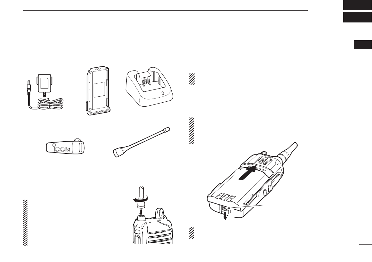
Supplied Accessories ■
Attaching/Using the Accessories ■
Antenna D
Connect the supplied antenna to the antenna
connector as shown.
CAUTION:
•NEVER carry the transceiver by
holding only the antenna.
•DO NOT
than listed on page 39.
•
Transmitting without an antenna
may damage the transceiver.
connect the antenna other
Battery Pack D
To attach the battery pack:
Slide the pack in the direction of the arrow (q), until the battery release button makes a ‘click’ sound.
NOTE: Push on the bottom of the pack to make sure the
release button is firmly locked.
To release the battery pack:
Push the battery release button in the direction of the arrow
(w), then slide the battery pack out.
NEVER release or attach the battery pack when the unit is
wet or soiled. This may result in water or dust getting into
the transceiver/battery pack, which may cause damage to
the transceiver.
NOTE: Keep the battery terminals clean. It's a good idea to
regularly clean them.
11
1
Page 8
ACCESSORIES
q
w
w
[MIC/SP] jack
Jack cover
q
q
q
w
1
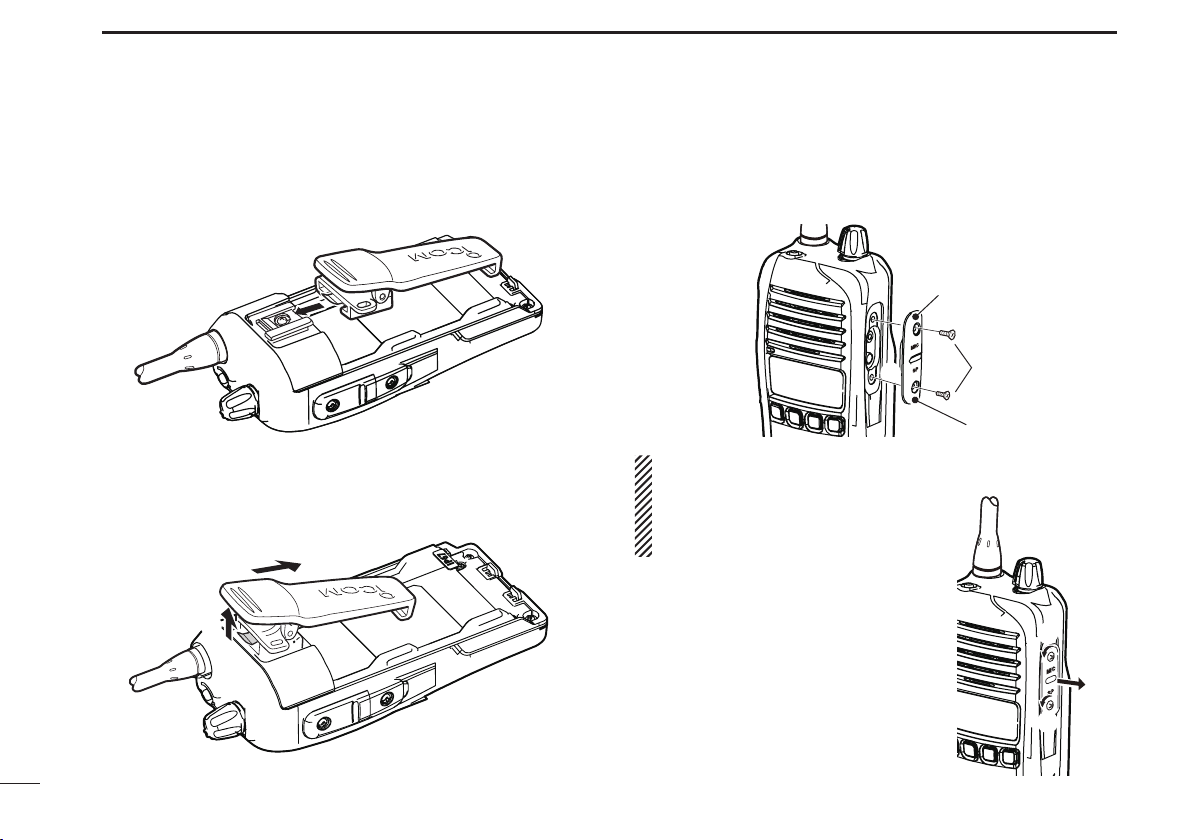
Belt Clip D
To attach the belt clip:
Release the battery pack if it is attached. q
Slide the belt clip in the direction of the arrow (see below) w
until a ‘click’ sound is heard.
To detach the belt clip:
Release the battery pack if it is attached. q
Pinch to lift the clip at w q (see below) and slide the belt clip
out of the holding bracket. (w)
Jack cover D
To attach the jack cover:
q Attach the jack cover to the [MIC/SP] jack.
w Tighten the screws.
CAUTION:
•Attach the jack cover when the op-
tional speaker-microphone is not
used.
•Usethesuppliedscrewsonly.
To detach the jack cover:
q Unscrew the screws using a phillips
screwdriver.
w Detach the jack cover for the speak-
er-microphone.
2
Page 9
UNIT DESCRIPTION
q
w
r
e
u
i
y
Microphone
Speaker
t
o!0!1!2
2
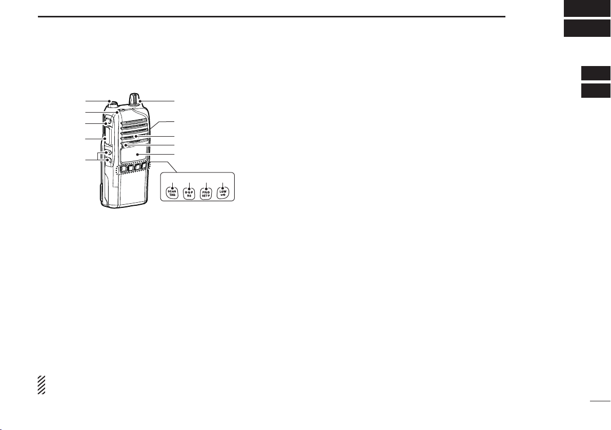
Front panel ■
q ANTENNA CONNECTOR
Connects the supplied antenna.
w TOP KEY [TOP]
Toggles Normal (N), Function (F) and Set (S) modes.
In Normal mode
Push to turn Function mode ON. (“F” is displayed) ➥
Push and hold for 2 seconds to enter set mode (p. 11). ➥
In Function mode
Push to return to Normal mode. ➥
When a receive channel is selected (once enabled), ➥
push and hold for 2 seconds to enter RX VFO (receive
frequency select) mode. (p. 29
NOTE : After 30 seconds in Function mode with no opera-
tion, unit will return to Normal mode.
)
e SIDE1 KEY [Side1]
In Normal mode
Push to toggle the monitor (open tone squelch) func- ➥
tion ON or OFF. (p. 10)
Push and hold for 2 seconds to activate the following ➥
functions in order:
•Tone squelch (only receive calls with same tone squelch
code). “T SQL ”appears. (p. 21)
•Pocketbeep (informs that a call was missed).“TSQL ë”
appears. (p. 21)
•Notoneoperation.“TSQLë” disappears.
In Function mode
Push to enter squelch setting mode, then push [CH Up] ➥
or [CH Down] to set the squelch level. (p. 10)
Push and hold for 2 seconds to turn the ATS (Auto- ➥
matic Transponder System) function ON or OFF.
(p. 28)
r PTT SWITCH [PTT] (p. 9)
Push and hold to transmit. Release to receive. ➥
A PTT hold function is also available. See page 30 for ➥
more information.
t CH UP/CH DOWN KEYS
y VOLUME CONTROL
Rotate to turn power ON or OFF and set operating volume.
u EXTERNAL SPEAKER JACK
Connect an optional speaker microphone. Ensure power is
OFF before connecting external devices.
121
3
Page 10

UNIT DESCRIPTION
2
i LCD DISPLAY (p. 5)
o SCAN/TAG KEY
In Normal mode
Push to start or stop scanning. This is dependent on ➥
tagged channels. (p. 17)
Push and hold for 2 seconds to set or clear displayed ➥
channel as tagged. (p. 17)
In Function mode
Push to enter the Selcall code channel selection mode, ➥
when a CB channel is selected. (p. 24)
Push and hold for 2 seconds to transmit to the Selcall code ➥
channel, when a CB channel is selected. (p. 25)
!0 O.G.P/RS KEY
In Normal mode
Push repeatedly to cycle through open, group and ➥
priority scan. (“
(pp. 18, 19)
Push and hold for 2 seconds to start/stop the repeater ➥
scan. (p. 20)
In Function mode
When a CB channel is selected, push to toggle the ➥
quiet function ON or OFF. (p. 27)
Push and hold for 2 seconds to display a history of re- ➥
ceived ID codes. (p. 26)
,” “ ” or “ ” will be displayed.)
!1 PRIO/SET.P KEY
In Normal mode
Push to change the selected channel to the priority ➥
channel. (p. 10)
Push and hold for 2 seconds to set the displayed chan- ➥
nel as the priority channel. (pp. 10, 19)
In Function mode
Push to transmit the smart-ring signal (in CTCSS ➥
mode). (p. 28)
Push and hold for 2 seconds to clear the priority chan- ➥
nel setting. (p. 10)
!2 LOW/
In Normal mode
Push to toggle the transmit output power level. (p. 9) ➥
Push and hold for 2 seconds to electronically lock all ➥
keys except [PTT], [Side1], [Top],
tion mode only) and
Push and hold again for 2 seconds to unlock all keys. ➥
In Function mode
➥
When a Repeater channel is selected, push to toggle
between duplex (repeater access) and simplex (no repeater access) operation.
settings.
Push and hold for 2 seconds to enter zone selection ➥
mode. (p. 8)
KEY
(while in Func-
.
This is dependent on default
4
Page 11
UNIT DESCRIPTION
q
w r
o
i
uy
e
!0
!1 !4
!5 !6
!3
!2
t
2
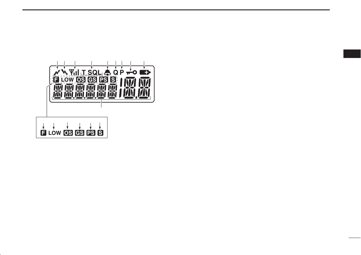
Display ■
q TRANSMIT INDICATOR
Appears when transmitting.
w BUSY INDICATOR
Appears while the channel is busy.
e SIGNAL STRENGTH INDICATOR
Indicates relative signal strength level. ➥
Blinks when ATS is in use. ➥
r TONE INDICATORS (p. 23)
“T” appears while the subaudible tone encoder is in use. ➥
“T SQL” appears while the tone squelch/DTCS squelch ➥
function is in use.
t BELL INDICATOR
Appears when the pocket beep function is in use. ➥
(p. 23)
Blinks when the specified selcall or smart ring call is ➥
received. (pp. 26, 28)
y QUIET INDICATOR
Appears when the quiet function is ON. (p. 27)
u PRIORITY CHANNEL INDICATOR
Appears when the priority channel is set. (p. 10)
i KEY LOCK INDICATOR
Appears when the keylock function is ON. (p. 8)
o BATTERY INDICATOR
Appears or blinks when the battery capacity decreases to
a specified level.
!0 ALPHANUMERIC DISPLAY
Displays the operating channel number, channel name,
set mode contents etc.
!1 FUNCTION INDICATOR
Appears when the function mode is ON. This allows sec-
ondary functions to be accessed.
2
5
Page 12

UNIT DESCRIPTION
2
!2 LOW POWER INDICATOR
Appears when low output power is selected, or the unit ➥
is operating in dry (alkaline) battery mode.
When the battery power decreases below the specified ➥
level, the unit will switch to low power automatically.
!3 OPEN SCAN INDICATOR
Appears when open scan is selected.
!4 GROUP SCAN INDICATOR
Appears when group scan is selected.
!5 PRIORITY SCAN INDICATOR
Appears when priority scan is selected.
!6 SCAN CHANNEL INDICATOR
Appears when the selected channel is specified as a
tagged channel.
INFORMATION ✓
“N/A” appears when the pushed key is not available.
6
Page 13
BASIC OPERATION
KEY
NUMBER
0
5
4
9
3
8
2
7
1
6
[CH Down]
CH
Down
[VOL]
3
Turning the Power ON ■
Prior to using the transceiver for the first time, the battery
pack must be fully charged for optimum life and operation.
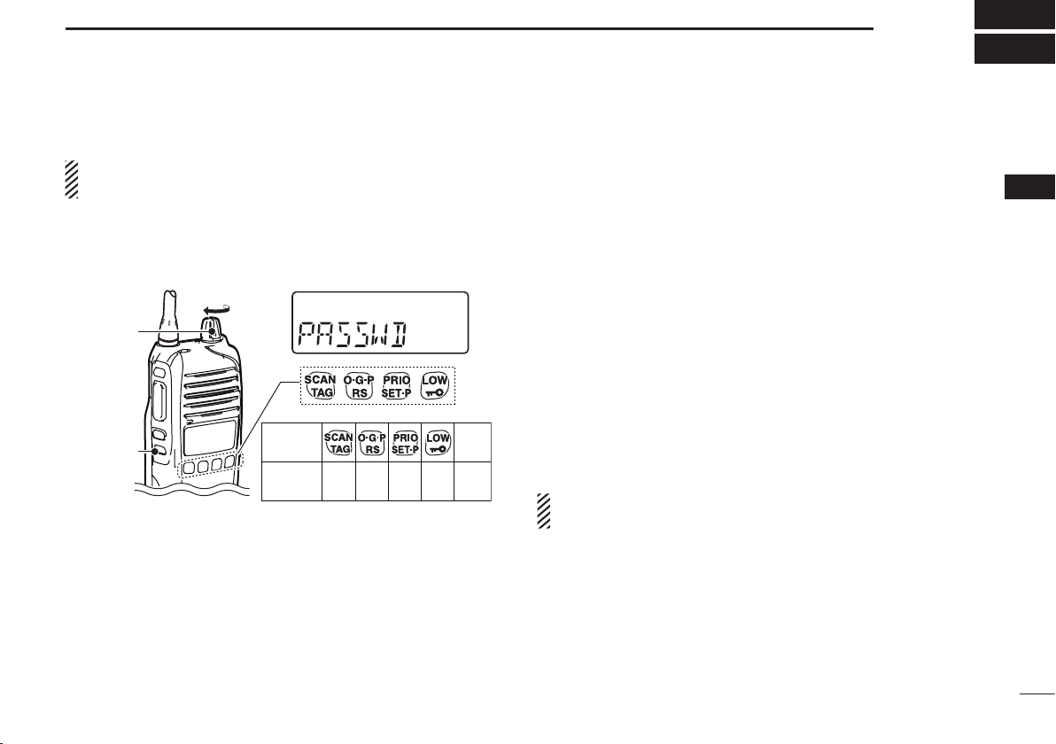
Rotate the [VOL] knob clockwise to turn the power ON. ➥
If the transceiver is programmed with a start-up password, ➥
this needs to be entered before operation can commence.
To input the password, first refer to the table below.
The password is made up of a four-digit code (e.g. 1234, 5420
etc). Push the corresponding buttons to enter your password.
Please note that each key represents two digits, meaning
that, for example, the passwords 3764 and 8769 are entered
in exactly the same way (i.e. no multiple or extended pushing required). When entering the password, no information
will be displayed on screen. If, after inputting four digits, the
“PASSWD” does not disappear, the password entered is incorrect. To try again, turn the power OFF and ON again.
Battery type ■
The transceiver can be used with the supplied Li-ion battery
pack or the optional battery case with third party AA batteries. In order to maximise the transceiver’s effectiveness, it is
important that the transceiver is switched to the appropriate
mode before operation.
To do this:
Ensure the transceiver power is OFF. q
While pushing and holding the [Top] and [PTT] buttons, w
rotate the volume knob to turn the power ON
•Thedisplaywill eithershow“dry”(AAbatterycase), or Li-ion.
(battery pack)
•Atthisstage,the[Top]and[PTT]buttonscanbereleased.
If the mode is now correct, the transceiver is ready for op- e
eration. If the incorrect mode is selected, repeat the above
process.
NOTE: In ‘dry’ mode, the transceiver is preset to low output
power. (1W)
3
7
Page 14

BASIC OPERATION
3
Backlight ■
The transceiver features a backlit LCD display for low-light
operation. The modes available for the backlight can be
changed via the set mode.
To enter set mode, push and hold [Top] for 2 seconds, then q
release.
Push [Top] several times until “Light” appears. w
Push [CH Up] or [CH Down] to set the backlight mode. e
•ON : Backlight is on continuously.
•A2 : Lights for 5 s ec onds when LCD indication is
changed or any key except [PTT] is pushed.
•AT : Lights for 5 seconds when a selcall signal is transmitted/
received or any key except [PTT] is pushed.
•OF : Backlight never lights.
r To exit set mode, push and hold [Top] for 2 seconds, or
turn transceiver OFF.
Keylock ■
This function electronically locks all keys except for [PTT],
[Side 1], [Top],
vent accidental channel changing and function access.
To lock the keypad:
Push and hold ➥
tion ON and OFF. “
locked.
8
(when in function mode only) and , to pre-
for 2 seconds to toggle the lock func-
” is displayed when the keypad is
Channel/Zone Selection ■
Channel Selection D
Changing channels on a UHF CB is important to ensure that you
can communicate with the intended person(s). The 80 channels
available on the UHF CB band also help to allow clear, uninterrupted communication. The IC-41W can access all 80 channels
on the UHF CB band, as well as designated repeater channels.
It is also capable of storing a combination of up to 48 receive
only and private channels. (dealer programmable)
Push the [CH Up] and [CH Down] buttons to scroll through the ➥
available channels.
•
It is also possible to push and hold these buttons for continuous scrolling.
• “CB-xx” appears when a CB channel is selected and RX-xx appears when
an RX channel is selected. (where “xx” represents the channel number)
Zone Selection D
A zone is a grouping of private channels, mainly used for
commercial applications. It allows only certain groups or business departments to communicate within the allocated zone.
Push [Top] to enter function mode, then push and hold q
for 2 seconds to enter the zone selection mode.
Push [CH Up] or [CH Down] to select the desired zone, w
then push
NOTE:
•
The selected channel is retained when the transceiver is turned off.
•TheCB-05,CB-R5andCB-35channelsareusedforemergency use, and are required to be left open for this use only. The
CB-22 and CB-23 channels are used for data transmission,
meaning voice transmission is inhibited.
(available only when two or more zones are set)
again to confirm.
Page 15

BASIC OPERATION
3
Receiving/Transmitting ■
NOTE: Transmitting without an antenna may damage the
transceiver. See page 1 for more information.
Receiving D
•If“TSQL”or“TSQLë” appears on the display, the user
will only be able to receive transmissions from others
who have programmed in the same tone squelch code.
(p. 21)
•If “T SQL” or“TSQLë” do not appear, the user can
receive all transmissions.
Select the desired operating channel. q
When receiving a signal, “ w
Push [Side 1] to toggle the monitor function ON or OFF. e
(p. 10)
Transmitting D
Wait for the channel to become clear to avoid interference. q
While pushing and holding [PTT], speak into the micro- w
phone at a normal voice level.
When transmitting, “ e
r
A PTT hold function is also available. See page 30 for details.
Important:
To maximise the clarity of the signal:
•Pause briey after pushing [PTT].This will ensure the
first part of your message is heard.
•Holdthemicrophoneabout5to10cmfromyourmouth.
” appears.
” appears.
•Transmit inhibit function – The transceiver will restrict
transmission under the following conditions:
- The channel is busy, or different CTCSS/DTCS code is
received. (depending on the transmission lockout function
setting)
- The selected channel is a receive only channel.
(e.g. CB22, CB23)
•Power Output
- Depending on the setting, it may be useful to reduce/increase the power output of the transceiver. Simply push
to toggle between high (5W) and low (1W). “LOW” will
be displayed when low output power is selected. Select
low power to conserve battery power, or high power for
longer distance communications.
•Time-out/Penalty/Lockout Timer
-
These functions limit transmission over the air and can be
activated or modified via dealer programming.
3
9
Page 16

BASIC OPERATION
3
Priority Channel ■
The priority channel allows the user to have quick access to a
specific channel. Only one channel can be set as the Priority
Channel. “P” appears when the Priority Channel is set.
To set the Priority Channel D
Select the desired channel using [CH Up] and [CH Down] q
Push and hold w
as the Priority Channel.
To switch to the Priority Channel D
Push ➥ to switch from the current channel to the Pri-
ority Channel. “N/A” appears when there is no Priority
Channel set.
To cancel the Priority Channel D
Push [Top] to enter the Function Mode, then push and ➥
hold for 2 seconds to cancel the Priority Channel. “P”
disappears.
for 2 seconds to set the current channel
Monitor ■
The monitor function opens the squelch or tone squelch, allowing weak signals to be received. This allows quick access
to an open squelch setting, to allow weak transmissions to
be received.
To toggle the monitor function on or off, push [Side 1]. ➥
•“
” blinks when the monitor function is in use.
Squelch ■
In order to receive signals clearly, the squelch level can be
adjusted to suit the operating environment. This eliminates
background noise when there are no signals present. A higher setting is better for inner city or noisy areas, and lower setting is more beneficial in quiet, rural and country areas.
To adjust the squelch sensitivity:
Push [Top] to enter second function mode, then push q
[Side 1] to enter the squelch setting mode.
Push [CH Up] or [CH Down] to adjust the squelch level w
from 0 to 9. (0= lowest setting, 9= highest setting)
Push [Side 1] to exit the squelch setting mode. e
10
Page 17
SET MODE
• Own ID*
• Lock-out • TOT • Power Save • Signal Moni • Battery Voltage
• Squelch Level
* • CTCSS/DTCS • Auto Power OFF • Backlight
• Mic Gain
• Beep Level
• Beep
• Roger Beep
• Scan Restart
• Scan Stop Timer
Starting item
: Push [Top]
4
The Set Mode allows the user to change various settings in
the transceiver to suit their operating requirements. Available
settings may differ, depending on the preprogramming of the
optional CS-41S
accessed by pushing and holding [Top] for 2 seconds. If no
key is pushed for 30 seconds, the transceiver will return to
the normal mode.
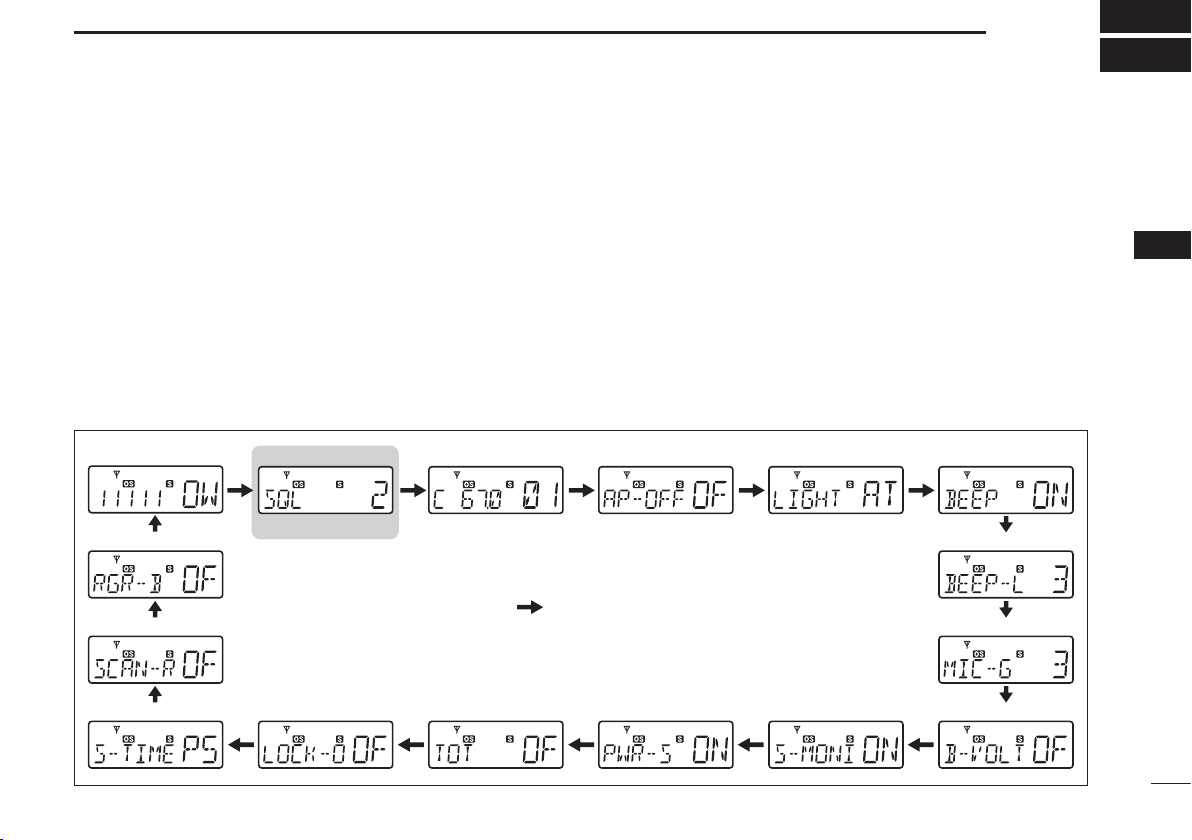
The following diagram shows the selection sequence of the
Set Mode Functions:
c l o n i n g s o f t w a r e . The Set Mode can be
D Set mode construction
When in the Set Mode:
Push [Top] to select the desired item. q
Push [CH Up] or [CH Down] to adjust the setting. w
Push and hold [Top] for 2 seconds to exit the Set Mode, or e
simply turn OFF the transceiver.
4
Please note that the default factory setting omits both the
squelch level and your own ID from the set mode sequence
These can be activated through the dealer programming software, if required. The squelch level can also be modified using the process described in section 5.
11
Page 18

SET MODE
Squelch level 2 (default) Squelch level 0 (“ ”appears)
CTCSS tone frequency
setting mode (default)
DTCS code setting mode
Push
Auto power OFF
is OFF (default)
2.0 hours setting
Backlight Auto (default) Backlight ON
4
Squelch D
In order to receive signals clearly, the squelch level can be
adjusted to suit the operating environment. This eliminates
background noise when there are no signals present. A higher setting is better for inner city or noisy areas, and lower setting is more beneficial in quiet, rural and country areas. There
are 10 available squelch levels. (0=lowest setting, 9=highest
setting)
D CTCSS/DTCS
Select the desired CTCSS tone frequency or DTCS code.
Pushing
CTCSS/DTCS is explained further in page 21.
toggles the CTCSS/DTCS setting mode.
Auto Power OFF D
The transceiver can be set to automatically turn off after a set
period of inactivity (i.e. no key has been pushed). This can be
set anywhere from 0.5 to 4.0 hours, in 0.5 hour steps.
D Backlight
The transceiver features a backlit LCD display for low-light operation.
•ON :Backlightisoncontinuously.
•A2(Auto2) :Lights for 5 seconds when LCD indication is
changed or any key except [PTT] is pushed.
•AT(Auto) :Lightsfor5secondswhen a selcall signal is
transmitted/received or any key except [PTT]
is pushed.
•OF(OFF) :Nobacklightavailable.
12
Page 19

SET MODE
Beep tone ON (default) Beep tone OFF
Beep level 3 (default) Beep level 1
Mic gain level 3 (default) Mic gain level 1
Battery voltage
OFF (default)
Battery voltage ON
Signal monitor ON (default) Signal monitor OFF
Power save ON (default) Power save OFF
4
Beep D
By default, confirmation beep tones are turned on. This can
be toggled ON or OFF by the set mode, for silent operation.
D Beep Level
The volume level of the key touch beep can be altered from 1
(softest) to 5 (loudest).
D
Mic Gain
The sensitivity of the microphone can be changed from 1
(minimum sensitivity) to 5 (maximum sensitivity). With a
higher sensitivity, the microphone will register softer voices,
although, it may pick up more ambient noise.
Battery Voltage D
The transceiver can be set to display the remaining battery
charge for a 2 second period after being turned ON.
4
Signal Monitor D
This function controls the mute condition during selcall code
signal and roger beep emission. By default, it is turned ON.
D Power Save
The auto power save function works by deactivating the receiver circuit, which reduces battery consumption. If a signal
is not received, or the unit is inactive for 5 seconds, the transceiver will enter power save mode.
13
Page 20

SET MODE
TOT OFF (default) TOT ON
Lockout OFF (default) Repeater lockout setting
Scan resume timer
P5 (default)
10 sec. setting
Scan restart timer
OFF (default)
Scan restart timer ON
Roger beep OFF (default) Roger beep ON
4
TOT (Time-Out Timer) D
The time-out timer limits the length of one continuous transmission. This helps conserve battery charge in the event of
accidental continuous transmission. By default, this is turned
OFF.
D Lock-out
This allows the user to select the temporary transmission inhibit capability, preventing communication overlap, which can
lead to missed or broken transmissions.
•RP(RepeaterLockout):Transmission is permitted only
while receiving a matched CTCSS
tone or when no signal is received.
•BU(BusyLockout) :Transmission is inhibited while receiving a signal.
•OF(OFF) :Norestrictions.
Scan Resume Timer D
The scan resume condition can be set as a pause (P5) or
timer scan (15/10/5). When a signal disappears, scanning will
resume after 5 seconds, regardless of the setting.
15/10/5 : Scan pauses for 15/10 or 5 seconds when a signal
is detected, then resumes.
P5 : Scan pauses until the signal disappears, and then
resumes after 5 seconds.
Scan Restart D
When in scan mode, the scan restart function resumes scanning 10 seconds after a transmission has been performed.
D Roger Beep
The roger beep emits a sound as acknowledgement that the
transmission has ceased.
14
Page 21

Own ID D
This function allows the user to edit their own ID (this function
is inactive by default, and can be turned on via dealer programming). Own ID is useful in commercial applications to allow
organisations to track where transmissions originate from.
To edit:
q
When in set mode, and own ID has been selected, push and
hold
w Push [CH Up] and [Ch Down] until the selected integer is
displayed on the blinking digit.
e
Push to set the blinking digit and progress to the next.
for 2 seconds to enter the own ID edit mode.
SET MODE
4
4
r Repeat this until all digits have been set correctly, the push
once more to set the Own ID.
15
Page 22

5
Station BStation A
Repeater
Channel 6
Channel 36
Channel 36
Channel 6
Uplink
(Repeater Output)
Downlink
(Repeater Input)
REPEATER OPERATION
Repeater Operation ■
Repeaters extend the operational range of the transceiver by
amplifying received signals. They are usually located on the
top of hills or mountains, as the elevation increases their effectiveness, allowing the user to transmit and receive over
greater distances. During standard operation, or simplex,
transceivers transmit and receive on the same frequency.
When operating in duplex mode (i.e. accessing a repeater),
the transceiver will need to transmit and receive on different
frequencies. The transceiver will automatically do this when
one of the repeater channels is selected.
To access the repeater channels:
Use the [CH Up] and [CH Down] keys to select a repeater ➥
channel.
Use the transceiver as you normally would. (see page 9) ➥
The transceiver can also search for accessible repeaters in
the area by using the repeater scan function. More detail of
this can be found in page 20.
Please note that the ACMA advises to avoid operation on
locally used repeater input channels (CH 31
71–78) and locally used repeater output channels (CH1–8
and CH 41–48) unless long distance communication via the
repeater facility is specifically required.
–38 and CH
16
NOTE:
When a repeater channel is selected, the display will show
“CB-R0X R1”, where “X” will change depending on the repeater channel selected.
Page 23

SCAN
Push
Push
Open scan is selected.
Group scan is selected.
Priority scan is selected.
Appears
Appears
Appears
Push
Appears
6
The IC-41W has four scan types, a tag function and four resume conditions. Scanning allows the transceiver to automatically scroll through all or selected channels in order to find a
transmission.
Scanning Preparation ■
The IC-41W scans all tagged channels and can be set for a
pause or timer resume condition. These items must therefore be
defined before starting a scan (except for the repeater search
scan), and must be set for each scan type independently.
Scan type selection D
Push (scan mode) several times to select the desired
scan type.
•Open,groupandpriorityscansareavailable(seebelow).
Tag Channel Setting D
Setting channels as ‘tag’ channels allows them to be included
in the scan function.
To set a tag channel:
Select the desired scan type. (to the left) q
Select the desired channel. ( w use the [CH Up] and
[CH Down] keys)
Push and hold e
ON or OFF. (
for 2 seconds to toggle the tag function
“ S” appears when the tag setting is on)
5
6
17
Page 24

6
Scan stop timer
P5 (default)
10 sec. setting
Open scan is selected.
Appears
Scan start channel
Blinks
SCAN
Scan Resume Condition D
The scan resume condition can be set as a pause (P5) or
timer scan (15/10/5). When a signal disappears, scanning will
resume after 5 seconds, regardless of the setting.
Push and hold [Top] for 2 seconds to enter set mode. q
Push [Top] several times until ‘S-TIME’ is displayed. w
Push [CH Up] or [CH Down] to select the scan resume e
time.
15/10/5 : Scan pauses for 15/10 or 5 seconds when a sig-
nal is detected, then resumes.
P5 : Scan pauses until the signal disappears, and
then resumes after 5 seconds.
r Rotate [VOL] to turn power OFF, or push and hold [Top] for
2 seconds to exit set mode.
Open Scan ■
The open scan function scans for transmitted signals, making
it easier to locate new stations for contact or listening purposes.
To start an open scan:
Push q
•“
w Push to start the scan.
When a signal is received, the scan will pause and resume e
according to the selected scan resume condition.
r Push
a few times until open scan is selected
” is displayed.
to cancel the scan.
18
Page 25

SCAN
Priority scan is selected.Group scan is selected.
Appears
Appears
Appears
Blinks
BlinksGroup scan starts.
Priority scan starts.
Priority channel
Scan start channel
6
Group and Priority Scan ■
Group and priority scans repeatedly watch a priority channel while scanning the specified tag channels. This is useful
when waiting for a call on the priority channel.
Group and priority scans behave differently when transmitting. Group scan allows the user to transmit on a busy or
priority channel. Priority scan will only allow transmission on
a priority channel. (or the channel scanning starts ON, if no
priority channel is set)
To initiate a group or priority scan:
Push q
•“
when priority scan is selected.
until group or priority scan is selected.
” appears when group scan is selected, and “ ” appears
Set the priority channel by holding down w for 2 sec-
onds while on the desired channel.
•
To cancel the priority channel, push [Top] to enter second function mode, then push and hold to remove the priority setting.
e
Push to start the scan.
r When receiving a signal, the scan will pause and resume
according to the selected scan resume condition.
t Push
to cancel the scan.
6
19
Page 26

6
Blinks
Scan
Scan
Searches for signal on the repeater
output channels.
Access to the repeater
automatically. (0.5 sec.)
Wait for a signal from
the repeater. (0.5 sec.)
Access to the next
repeater automatically.
(When no reply signal is received.)
Scan is cancelled automatically.
Scan start
channel
Appears
Appears
NOTE: Excludes Emergency Repeater ‘CB-R5.’
SCAN
Repeater ■
The repeater search scan is not only used to search for a signal on the repeater channels, but also to access a repeater by
transmitting automatically in sequence. The repeater search
function searches available repeaters in the area .The re-
20
peater scan detects signals on repeater channels. When the
repeater is not busy, it will be available for use. The repeater
scan will stop should any activity be detected (The scan is
cancelled when receiving a signal, such as stations communicating in simplex operation on a repeater output channel).
•ExcludesemergencyrepeaterchannelCB-R5.
To start the repeater scan:
Select the desired repeater output channel and push and q
hold
w When a signal is received on the repeater channel, scan-
ning will stop. (during the second cycle scanning the repeater channels, three high beeps will sound when a signal is received, and three low beeps will sound when no
signal is received)
Push e
the repeater scan cannot be cancelled)
for 2 seconds to start the repeater scan.
to cancel the scan manually. (when transmitting,
Repeater search scan flow D
Page 27

TONE SQUELCH
CTCSS tone setting mode DTCS code setting mode
DTCS code
CTCSS tone frequency
List number
(grey line)
List number
(grey line)
7
Tone squelch allows the user to only hear transmissions
with others who have set the same code on their transceiver.
This is useful in business applications or in situations where
small children are present, so that profanities and nonsense
transmissions cannot be heard. Please note that this is not
a privacy function, as those without tone squelch activated
will still hear your transmission. Please also be aware that
transmissions that cannot be heard will cause the channel
to become busy. The IC-41W is equipped with both CTCSS
(Continuous Tone-Coded Squelch System) and DTCS (Digital Tone Coded Squelch). Both methods work by producing a
sub-audible tone or code which is either accepted or rejected
by the receiving transceiver, depending on whether the tone
matches its code. If accepted, the squelch will open, allowing the transmission to be heard. If rejected, the squelch will
remain closed and the transmission will be muted.
In addition to standard tone squelch, a pocket beep function
is also available. This function uses CTCSS or DTCS for calling and can be used in a similar fashion to a pager. It informs
the user that someone has called while away from the transceiver.
Setting Up a CTCSS/DTCS Code D
Select the desired channel (excluding channel 5 or 35) q
using the [CH Up] and [CH Down] keys.
Push and hold [Top] for 2 seconds to enter set mode. w
Repeatedly push [Top] while in set mode until “C” or “D,” e
followed by a number appears on the display.
r Push
set mode.
t Repeatedly push [CH Up] and [CH Down] to set the de-
sired CTCSS tone frequency/DTCS code.
y Rotate [VOL] to turn the power OFF, or push and hold
[Top] for 2 seconds to exit set mode.
to toggle between CTCSS set mode and DTCS
7
21
Page 28

TONE SQUELCH
Freq.
67.0
69.3
71.0
71.9
74.4
77.0
79.7
82.5
85.4
88.5
91.5
No.
01
02
03
04
05
06
07
08
09
10
11
Freq.
94.8
97.4
100.0
103.5
107.2
110.9
114.8
118.8
123.0
127.3
131.8
No.
12
13
14
15
16
17
18
19
20
21
22
Freq.
136.5
141.3
146.2
151.4
156.7
159.8
162.2
165.5
167.9
171.3
173.8
No.
23
24
25
26
27
28
29
30
31
32
33
Freq.
177.3
179.9
183.5
186.2
189.9
192.8
196.6
199.5
203.5
206.5
210.7
No.
34
35
36
37
38
39
40
41
42
43
44
Freq.
218.1
225.7
229.1
233.6
241.8
250.3
254.1
No.
45
46
47
48
49
50
51
Code
023
025
026
031
032
036
043
047
051
053
054
065
071
072
073
074
114
115
116
122
125
No.
01
02
03
04
05
06
07
08
09
10
11
12
13
14
15
16
17
18
19
20
21
Code
131
132
134
143
145
152
155
156
162
165
172
174
205
212
223
225
226
243
244
245
246
No.
22
23
24
25
26
27
28
29
30
31
32
33
34
35
36
37
38
39
40
41
42
Code
251
252
255
261
263
265
266
271
274
306
311
315
325
331
332
343
346
351
356
364
365
No.
43
44
45
46
47
48
49
50
51
52
53
54
55
56
57
58
59
60
61
62
63
Code
371
411
412
413
423
431
432
445
446
452
454
455
462
464
465
466
503
506
516
523
526
No.
64
65
66
67
68
69
70
71
72
73
74
75
76
77
78
79
80
81
82
83
84
Code
532
546
565
606
612
624
627
631
632
654
662
664
703
712
723
731
732
734
743
754
No.
85
86
87
88
89
90
91
92
93
94
95
96
97
98
99
100
101
102
103
104
7
22
• Available CTCSS tone frequency list (Hz)
NOTE: The transceiver has 51 tone frequencies and consequently their spacing is narrow compared with units
having 38 tones. Therefore, some tone frequencies may
receive interference from adjacent tone frequencies.
• Available DTCS code list
Page 29

TONE SQUELCH
Appears
Blinks
7
Turning the tone squelch operation D ON or
OFF
Select the desired channel (excluding channel 5 or 35) us- q
ing the [CH Up] and [CH Down] keys.
Set the desired CTCSS tone frequency/DTCS code in set w
mode. (see page 12)
Push and hold [Side 1] for 2 seconds several times until e
“T SQL” appears. Each 2 second push will scroll through,
“T SQL ë ” (pocket beep) and blank (OFF).
r When the received signal includes a matching tone or
code, the squelch opens and the signal can be heard.
When the received signal is not matched, the squelch will
not open, but “
To open the squelch manually, push [Side 1].
t The transceiver can now be operated as per normal.
y To cancel the tone squelch operation, push and hold
[Side1] for 2 seconds several times until both “T SQL,”
“T SQL ë” disappear.
NOTE: CTCSS tone frequency/DTCS code and tone
squelch ON/OFF settings are automatically stored in
memory channels for easy recall.
” will appear to show the channel is busy.
Setting up and using the pocket Beep D
Select the desired channel (excluding channel 5 or 35) q
using the [CH Up] and [CH Down] keys.
Set the desired CTCSS tone frequency/DTCS code in set w
mode. (see previous section)
Push and hold [Side 1] for 2 seconds several times until e
“T SQL ë” appears. Each 2 second push will scroll
through “T SQL,” “T SQL ë” (pocket beep) and blank
(OFF).
r When the received signal includes a matching tone or
code, the transceiver will emit a beep every 10 seconds,
and “ë” will blink.
t Push [PTT] to answer and stop the alert. The transceiv-
er will automatically switch to tone squelch operation.
(“T SQL” will be displayed)
7
23
Page 30

8
TX code
Appears
Transmitting
SELCALL (Selective Calling)
In addition to tone squelch operation for silent stand-by, SelCall operation is available. In tone squelch operation, there
are 155 tone/code options when making a call. SelCall offers
a much more versatile 100,000 options when using 5-tone.
Other options available in SelCall are the ability to call another unit or group operating on the same channel, as well
as station code/name information, status messages, answer
back functionality and auto scan start. These, and many more
can be set up via dealer programming.
NOTE: Channels 5 and 35 are used for emergency and
channels 22 and 23 are used for data channels, meaning
SelCall is not available on these channels. SelCall transmission is restricted to a total of 3 seconds. If trying to
transmit longer than 3 seconds, “N/A” is displayed (when
is pushed) or an error beep is emitted. (when [PTT] is
pushed)
Calling ■
TX Code Channel Selection D
“ ” allows the user to change the TX code channel with
[CH Up] or [CH Down]. TX code refers to the transmitting Selcall mode. A maximum of 32 TX code channels can be preprogrammed into the transceiver using the optional CS-41S
c l o n i n g s o f t w a r e .
To select a TX code channel D
Select the desired CB channel (CB-XX) except channels q
5 and 35.
Push [Top] to enter function mode, then push w
the TX code channel selection mode. (the code channel
name is displayed instead of the code if it has been programmed via the CS-41S c
e Push [CH Up] or [CH Down] to select the desired TX code
channel.
r Push [PTT] to transmit the selected TX code channel, or
push
to the stand-by mode.
TIP:
All 32 TX code channel names can be assigned via the
CS-41S
lect the channel and find other users, etc.
to set the selected TX code channel and return
c l o n i n g s o f t wa r e . This allows the user to easily se-
l o n i n g s o f t w a r e )
to enter
24
Page 31

SELCALL (Selective Calling)
The editable digit starts blinking
Appears
Transmitting
Appears
Transmitting
8
TX code number edit D
“ ” enables the user to change the TX code digits contained
in the TX code channel. The group call function works by allowing the user to edit a special ‘group code’ into the last 2
digits of the SelCall ID code.
To edit a TX code:
Select the desired CB channel (CB-XX) except channels q
5 and 35.
Push [Top] to enter function mode, then push w
ter the TX code channel selection mode. If desired, push
[CH Up] or [CH Down] to select the required TX code
channel.
Push and hold e
code edit mode.
r Push to select the desired digit to be edited.
t Push [CH Up] or [CH Down] to set the desired code. Se-
lect ‘
✱’ when group code is set.
y Push
digit.
to set the digit and move to the next editable
for 2 seconds again to enter the TX
to en-
u Repeat step t and y to input all digits.
i After setting the final digit, push
return to the TX code channel selection mode.
o Push [PTT] to transmit the selected TX code channel, or
push
to the stand-by mode.
NOTE: the allowed editable digits can only be set via the
CS-41S
To transmit an individual call:
Push [Top] to enter function mode, then push and hold ➥
for 2 seconds to transmit.
to set the selected TX code channel and return
c l o n i n g s o f t w a r e . (optional)
to set the code and
8
25
Page 32

SELCALL (Selective Calling)
Blink
Blink
8
Receiving ■
26
Receiving an individual call (default setting) D
“PiRo” beeps sound. ➥
The received code channel name/number is displayed ➥
“ ➥ ë” and the displayed channel info blink, and Selcall mute
is released when quiet mode is activated.
While pushing and holding [PTT], speak into the micro- ➥
phone at a normal voice level.
NOTE:
•When theIDdecodefunction isactivated,thereceived
ID code is displayed instead of the channel name, and
memorised by the transceiver. The ID decode function
can be activated via the CS-41S
•RXcodemeansthereceivingSelCallmade.Amaximum
of 8 RX code channels can be pre-programmed into the
transceiver using the optional CS-41S
w a r e .
•Varioussettingsandconditionscan besetforwhenan
individual call is received via the optional CS-41S
i n g s o f t w a r e . See the help file for more details.
c l o n i n g s o f t w a r e .
c l o n i n g s o f t -
Recalling a memorised receive selcall code D
Push [Top] to enter the function mode, then push and hold q
for 2 seconds to display the memorised RX code.
Push [CH Up] or [CH Down] to select the desired RX w
code.
Push [Top] to enter the function mode, then push and hold e
for 2 seconds to transmit the code to the selected
channel.
NOTE: Up to 8 receive code channels, and the receive
condition, can be programmed via the CS-41S cloning
software. Consult the CS-41S help file for more information.
When receiving a group call: D
“PiPi” tone sounds. ➥
“ ➥ ë” and “GROUP” blink, and Selcall mute is released
when quiet mode is activated.
While pushing and holding [PTT], speak into the micro- ➥
phone at a normal voice level.
c l o n -
➥ The group receive condition can be set via the CS-41S
c l o n i n g s o f t w a r e . Consult the CS-41S help file for more
information.
Page 33

SELCALL (Selective Calling)
Appears
Blinks
8
Quiet Mode ■
When quiet mode is turned ON, selcall mute is activated and
allows silent operation until a selcall code is received. Push
[Top] to enter function mode, then push
mode ON or OFF. (“Q” appears when quiet mode is in use)
DTo monitor the channel:
Push [Side 1] to release the mute. (audio is emitted)
•
“ ” blinks when the monitor function is in use.
DTo enable selcall mute:
When “ ” blinks, push [Side 1] to mute the channel.
•“
” disappears.
NOTE: the unmute condition may automatically revert to
mute after a specified time, depending on the pre-settings.
to toggle quiet
Stun ■
When a specified ID, set as a kill ID, is received, the stun ➥
function is activated (PC programming is required). This is
designed to disable the transceiver for security purposes.
When a killer ID is received, the transceiver switches to ➥
the “password required” condition. Entering the correct
password via the keypad is necessary to operate the
transceiver again. The required password is set via PC
programming.
8
27
Page 34

9
BlinkAppears
Blinks Blinks
Appears If no reply is received
OTHER FUNCTIONS
Smart Ring/ATS D
These functions have an answer back feature and allow
confirmation if a call has reached the receiving party, even if
the operator is temporarily away from the transceiver. These
functions also allow the user to determine if another compatible Icom unit is in range, which is useful in convoy situations
where groups may be separated. Smart ring is a manual confirmation, while ATS is automatic.
To set the smart ring function:
Set the same CTCSS tone frequency on all transceivers q
in the group and turn the tone squelch ON.
Push [Top] to enter function mode, then push w to send
the smart-ring call.
•“ ” appears.
•When a member of the group answers the call, “ë” and
“FOUND” blink.
•Whenananswerisn’treceived,thetransceiveremitsshortfailure beep tones and “FAILD” appears.
(see page 21)
NOTE: The smart ring setting is for the calling station only.
A called party automatically sends an answer back without
any pre-settings. All IC-41W units operating on the same
operating channel will answer back to the call in the surrounding communication area. When an RX channel is
selected, “N/A” appears.
To set the ATS function:
Push [Top] to enter function mode, then push and hold q
[Side 1] for 2 seconds to turn the ATS function ON.
•
When an RX channel is selected, an error beep is emitted
•Thetransceiverwillsendasearchingsignalevery60seconds
automatically.
•“ ” appears and “ ” starts blinking on the display when the
function is activated.
•When the transceiver receives an answer back signal,
“ ” stays on the display until the next search transmit.
•If noreplyis received,“ ” blinks until the next search transmit.
e
Push [PTT] to answer and to stop the display blinking.
28
NOTE: The smart ring function is only available when the
called station has the same CTCSS tone frequency and
operating channel as the user.
w
Push [Top] to enter function mode, then push and hold
[Side 1] for 2 seconds to turn the ATS function OFF.
Page 35

OTHER FUNCTIONS
“Enable” setting“Inhibit” setting
RX VFO modeRX channel
(in function mode)
Appears when Narrow
channel spacing is set.
Narrow channel spacing
(12.5 kHz steps)
Wide channel spacing
(25 kHz steps)
9
RX Frequency D
The frequency of the RX channels can be re-programmed
within the 450–520 MHz frequency range, to allow the transceiver to listen to communications outside the standard CB
range. Please note that it is not possible to transmit on these
channels.
As standard, the RX channels will not appear when scrolling
through the list with [CH Up] and [CH Down]. In order to do
so, the RX channels will need to be enabled.
To enable individual receive channels:
While pushing and holding q
ceiver ON to enter the receive channel enable mode.
Select the desired channel with [CH Up] and [CH Down], w
then push
hibited.
e Turn the power OFF, then ON. (The enabled receive chan-
nels will now appear when scrolling through the channels)
to either set the channel as enabled or in-
and , turn the trans-
To program the RX frequencies:
Select the desired RX channel (RX-XX), once enabled. q
Push [Top] to enter function mode, then push and hold w
[Top] for 2 seconds to enter the RX VFO mode.
Push e
r Push [CH Up] and [CH Down] several times to select the
desired frequency. The frequency changes according to
the wide/narrow setting.
t
Push to select the desired digit to be altered.
to toggle between wide and narrow bandwidth.
9
☞ Continued on the next page.
29
Page 36

OTHER FUNCTIONS
9
D RX Frequency
To program the RX frequencies: (Continued)
y Edit the desired digit with [CH Up] and [CH Down].
u Push to set the digit and move to the next editable
digit.
i Repeat steps y and u to input the desired frequency.
o Push and hold [Top] for 2 seconds to return to normal
operation. The RX frequency is now memorised.
PTT Hold D
The PTT switch can be operated as a one touch PTT switch
(each push toggles between transmit/receive). Using this
function makes it possible to transmit without holding down
the PTT switch. To prevent accidental continuous transmission with this function, the time-out timer function is automatically set. See page 9 for details.
Turn power OFF q
While pushing and holding [PTT], turn power ON to turn w
the PTT hold function ON. (P-HOLD ON is displayed momentarily)
e Push [PTT] to transmit, and push once again to return to
receive/standby. (“
r Repeat steps q and w to turn PTT hold OFF.
NOTE: The PTT hold function can only be used with the
PTT switch on the transceiver. By attaching an optional
microphone, the PTT hold functionality will be lost, as the
PTT switch on the microphone must be used.
” appears while transmitting)
30
Page 37

Caution ■
Misuse of Lithium-ion batteries may result in the following
hazards: smoke, fire, or the battery may rupture. Misuse
can also cause damage to the battery or degradation of
battery performance.
R DANGER! Use and charge only specified Icom battery
packs with Icom radios or Icom charger. Only Icom battery
packs are tested and approved for use and charge with Icom
radios or Icom charger. Using third-party or counterfeit battery packs or charger may cause smoke, fire, or cause the
battery to burst.
Battery caution
R DANGER! DO NOT hammer or otherwise impact the bat-
tery. Do not use the battery if it has been severely impacted or
dropped, or if the battery has been subjected to heavy pressure. Battery damage may not be visible on the outside of the
case. Even if the surface of the battery does not show cracks
or any other damage, the cells inside the battery may rupture
or catch fire.
BATTERY CHARGING
R DANGER! NEVER use or leave battery packs in areas
with temperatures above +60˚C. High temperature buildup in
the battery, such as could occur near fires or stoves, inside
a sun heated car, or in direct sunlight may cause the battery
to rupture or catch fire. Excessive temperatures may also degrade battery performance or shorten battery life.
R DANGER! DO NOT expose the battery to rain, snow, sea-
water, or any other liquids. Never charge or use a wet battery.
If the battery gets wet, be sure to wipe it dry before using.
R DANGER! NEVER incinerate used battery packs since in-
ternal battery gas may cause them to rupture, or may cause
an explosion.
R DANGER! NEVER solder the battery terminals or NEVER
modify the battery pack. This may cause heat generation, and
the battery may rupture, emit smoke or catch fire.
R DANGER! Use the battery only with the transceiver for
which it is specified. Never use a battery with any other equipment, or for any purpose that is not specified in this instruction manual.
R DANGER! If fluid from inside the battery gets in your eyes,
blindness can result. Rinse your eyes with clean water, without rubbing them, and see a doctor immediately.
10
9
1010
31
Page 38

BATTERY CHARGING
10
R WARNING! Immediately stop using the battery if it emits
an abnormal odor, heats up, or is discolored or deformed. If
any of these conditions occur, contact your Icom dealer or
distributor.
R WARNING! Immediately wash, using clean water, any part
of the body that comes into contact with fluid from inside the
battery.
R WARNING! NEVER put the battery in a microwave oven,
high-pressure container, or in an induction heating cooker.
This could cause a fire, overheating, or cause the battery to
rupture.
CAUTION: Always use the battery within the specified temperature range, –20˚C to +60˚C. Using the battery out of its
specified temperature range will reduce the battery’s performance and battery life.
CAUTION: Shorter battery life could occur if the battery is
left fully charged, completely discharged, or in an excessive
temperature environment (above +50˚C) for an extended
period of time. If the battery must be left unused for a long
time, it must be detached from the radio after discharging.
You may use the battery until the remaining capacity is about
half, then keep it safely in a cool dry place with the temperature range as below:
–20˚C to +50˚C (within a month)
–20˚C to +35˚C (within three months)
Charging caution D
R DANGER! NEVER charge the battery pack in areas with
extremely high temperatures, such as near fires or stoves,
inside a sun heated car, or in direct sunlight. In such environments, the safety/protection circuit in the battery will activate,
causing the battery to stop charging.
R WARNING! NEVER charge or leave the battery in the
battery charger beyond the specified time for charging. If the
battery is not completely charged by the specified time, stop
charging and remove the battery from the battery charger.
Continuing to charge the battery beyond the specified time
limit may cause a fire, overheating, or the battery may rupture.
R WARNING! NEVER insert the transceiver (battery at-
tached to the transceiver) into the charger if it is wet or soiled.
This could corrode the battery charger terminals or damage
the charger. The charger is not waterproof.
CAUTION: NEVER charge the battery outside of the specified temperature range: BC-160 and BC-171 (0˚C to +45˚C; ).
BC-119N and BC121N (+10˚C to +40˚C;). Icom recommends
charging the battery at +20˚C. The battery may heat up or
rupture if charged out of the specified temperature range.
Additionally, battery performance or battery life may be reduced.
32
Page 39

BATTERY CHARGING
AC adapter
Optional OPC-515L
(for 13.8 V power
source) or CP-23L
(for 12 V cigarette
lighter socket) can
be used instead of
the AC adapter.
*
TransceiverBattery
pack
Tu rn power OFF
CAUTION: NEVER connect the OPC515L to a power source using reverse
polarity. This will ruin the battery charger.
White line: Black line
:
*
Screws supplied
with the charger
adapter
AD-106
Connectors
Plugs
10
The BC-160 provides rapid charging of the Li-ion battery
packs.
Charging period: Approximately 3.5 hours.
The following items are additionally required:
•AnACadapterortheDCpowercable(OPC-515L/CP-23L)
Rapid charging with the BC-160 ■
Optional battery chargers ■
AD-106 installation D
The AD-106 c h a r g e r a d a p t e r must be installed into the BC119N or BC-121N before battery charging.
q Connect the AD-106
BC-121N.
w Install the AD-106 into the holder space of the BC-119N or
BC-121N with the supplied screws.
c h a r g e r a d a p t e r and the BC-119N/
1010
33
Page 40

BATTERY CHARGING
AC adapter
AD-106 charger
adapter is installed
in BC-119N.
Optional OPC-515L
(for 13.8 V power
source) or CP-23L
(for 12 V cigarette
lighter socket) can
be used instead of
the AC adapter.
Transceiver
Battery
pack
Tu rn power OFF
CAUTION: NEVER connect the OPC515L to a power source using reverse
polarity. This will ruin the battery charger.
White line: Black line
:
*
*
Battery
pack
AD-106 charger
adapters are installed
in each slot.
Transceiver
DC power cable (OPC-656)
(Connect with the DC power supply; 13.8 V/at least 7 A)
*About the OPC-656
Red line : Black line :
Tu rn power OFF
AC adapter
(Purchased
separately)
10
Rapid charging with the BC-119N+AD-106 D
The optional BC-119N provides rapid charging of the Li-ion
battery pack.
Charging period: Approximately 3.5 hours.
The following items are additionally required.
•AD-106c h a r g e r a d a p t e r (purchase separately)
•AnACadapterortheDCpowercable(OPC-515L/CP-23L).
34
Rapid charging with the BC-121N+AD-106 D
The optional BC-121N allows up to 6 battery packs to be
charged simultaneously.
Charging period: Approximately 3.5 hours.
The following items are additionally required.
•SixAD-106chargeradapters
•An AC adapter (BC-157S) or the DC powercable(OPC-
656)
Page 41

IMPORTANT: Battery charging caution
Guide rail
Tabs
Ensure the guide tabs on the battery pack are correctly
aligned with the guide rails inside the charger adapter.
(This illustration is described with the BC-160)
BATTERY CHARGING
10
10
35
Page 42

11
q w
Once the transceiver is locked in place,
it will swivel 360 degrees.
OPTIONS
MB-93 contents ■
Qty.
q Belt clip ��������������������� 1
w Base clip �������������������� 1
Attaching ■
q Release the battery pack if it is attached. (p. 1)
w Slide the base clip in the direction of the arrow until the
base clip is locked and makes a ‘click’ sound.
r Clip the belt clip to a part of your belt. And inser t the
transceiver into the belt clip until the base clip inserted
fully into the groove.
t Once the transceiver is locked in place, it swivels as illus-
trated below.
36
e Attach the battery pack. (p. 1)
Page 43

Detaching ■
q
w
q Turn the transceiver upside down in the direction of the
arrow and pull out from the belt clip.
OPTIONS
w Release the battery pack if it is attached. (p. 1)
e Pinch the clip (q), and slide the base clip in the direction
of the arrow (w).
11
CAUTION:
HOLD THE TRANSCEIVER TIGHTLY, WHEN HANGING
OR DETACHING THE TRANSCEIVER FROM THE BELT
CLIP.
Otherwise the transceiver may not be attached to the
holder or swivel properly if the transceiver is accidentally
dropped and the base clip is scratched or damaged.
11
37
Page 44

OPTIONS
Alligator type clip
To attach the speaker-mic.
to your shirt or collar, etc.
PTT switch
Transmits while pushed
Receives while released
Microphone
Speaker
Turn the transceiver power
OFF when connecting the
HM-168LWP.
Hand tighten
CAUTION: Attach the connector snugly.
A loose connection will allow water intrusion into the
connector.
11
Optional HM-168LWP description ■
38
NEVER immerse the connector in water. If the connector
becomes wet, be sure to dry it BEFORE attaching it to the
transceiver.
NOTE: The microphone is located as shown in the dia-
gram above. To maximize the readability of your transmitted signal (voice), hold the microphone approximately 5
to 10 cm from your mouth, and speak in a normal voice
level.
Attachment ■
Attach the connector of the speaker-microphone into the [SP
MIC] jack on the transceiver and tighten the screws with fingers.
NOTE: Use only your fingers instead of tools to tighten
the screws.
IMPORTANT: Keep the [SP MIC] jack cover attached to
the transceiver when the speaker-microphone is not in
use.
Page 45

OPTIONS
11
BATTERY PACK D
Battery pack Voltage Capacity Battery life*
BP-232WP 7.4 V
* When the power save function is turned ON, and the operating
periods are calculated under the following conditions;
TX : RX : standby = 5 : 5 : 90
2250 mAh (min.)
2300 mAh (typ.)
15.0 hrs.
CHARGERS D
• BC-119N d e s k t o p c h a r g e r + AD-106 c h a r g e r a d a p t e r
+ BC-145SV a c a d a p t e r
For rapid charging of battery packs. An AC adapter is supplied with
the charger.
Charging time: approximately 3.5 hours.
• BC-121N m u l t i -c h a r g e r + AD-106 c h a r g e r a d a p t e r (6 pcs.)
+ BC-157S a c a d a p t e r
For rapid charging of up to 6 battery packs (six AD-106’s are required)
simultaneously. An AC adapter should be purchased separately.
Charging time: approximately 3.5 hours.
• BC-160 d e s k t o p c h a r g e r + BC-145SV a c a d a p t e r
For rapid charging of battery packs. An AC adapter is supplied with
the charger.
Charging time: approximately 3.5 hours.
BELT CLIPS D
• MB-93 s w i v e l b e l t c l i p
• MB-94 b e lt c l i p
Exclusive alligator-type belt clip.
• MB-96N/96F l e at h e r b e l t h a n g e r
DC CABLES D
• CP-23L c i g a r e t t e l i g h t e r c a b l e
Allows charging of the battery pack through a 12 V cigarette lighter
socket. (For BC-119N/BC-160)
• OPC-515L/OPC-656 d c p o w e r c a b l e s
Allows charging of the battery pack using a 13.8 V power source
instead of the AC adapter.
OPC-515L : For BC-119N/BC-160
OPC-656 : For BC-121N
OTHER OPTIONS D
• HM-168LWP sp e a k e r -m i c r o p h o n e
Combination speaker-microphone that provides convenient opera-
tion while hanging the transceiver from your belt.
• FA-SC72U a n t e n n a
470–520 MHz
• FA-SC73US
450–490 MHz
• AD-98FSC
•CS-41S c l o n i n g s o f t w a r e + OPC-478UC c l o n i n g c a b l e
Provide quick and easy programming of such settings as RX fre-
quencies and Set modes contents.
•MB-130 v e h i c l e c h a r g e r b r a c k e t
Mounts the BC-160 desktop charger on to variety of place in ve-
hicle.
Approved Icom optional equipment is designed for optimal performance when used with an Icom transceiver.
Icom is not responsible for the destruction or damage to an Icom
transceiver in the event the Icom transceiver is used with equipment
that is not manufactured or approved by Icom.
s t u b b y a n t e n n a
a n t e n n a c o n n e c t o r a d a p t e r
11
39
Page 46

12
SPECIFICATIONS
D General
•Frequencycoverage
TX : 450–480 MHz
(includes all 80 CB channels)
RX : 450–520 MHz
•Mode :8K50F3E/16K0F3E
•Channelspacing
CB channel : 12.5 kHz
Private channel : 12.5/25 kHz
•Currentdrain(at7.2V) :TX(at5W) 1.9A
Max. audio 300 mA max.
•Powersupplyrequirement:7.2VDCnominal*
(negative ground)
*Specified Icom’s battery pack only
•Frequencystability :±2.5ppm(–30°Cto+60°C)
•Antennaimpedance :50Ω nominal
•Dimensions :53.0(W)× 120(H) × 37(D) mm
(Projections not included)
•Weight :
Approx. 310 g (including BP-232WP)
D Transmitter
•Outputpower :5W
•Modulationsystem :Variablereactancefrequency
modulation
•Max.frequencydeviation :±2.5kHz/±5.0kHz
•Spuriousemissions :70dB(min)
•Adjacentchannelpower :68dB/75dB(typical)
•Externalmic.connector :3-conductor2.5(d)mm/2.2kΩ
D Receiver
•Receivesystem :Doubleconversion
superheterodyne
•Sensitivity(12dBSINAD) :0.25µV(typical)
•Squelchsensitivity :0.25µV(typical;Threshold)
•Intermodulationrejectionratio :74dB(typical)
•Spuriousresponserejectionratio:70dB(min)
•Adjacentchannelselectivity :65dB/75dB(typical)
•Audiooutputpower :0.5W(typical)at5%distor-
tion with an 8 Ω load
•Externalspeakerconnector :2-conductor3.5(d)mm/8Ω
All stated specifications are subject to change without
notice or obligation.
40
Page 47

WARRANTY AND REGISTRATION
13
ICOM LIMITED WARRANTY
Icom Incorporated is proud of its advanced technology and the high quality of
workmanship and components included in the production of every product. Our
goods come with guarantees that cannot be excluded under the Australian
Consumer Law. You are entitled to a replacement or refund for a major failure
and for compensation for any other reasonably foreseeable loss or damage.
You are also entitled to have the goods repaired or replaced if the goods fail to
be of acceptable quality and the failure does not amount to a major failure.
Icom (Australia) Pty. Ltd., the authorised Icom Distributor, warrants this Icom
product within Australia to be free from defects in material or workmanship for
the applicable period indicated below:
• Radios:
Two (2) years from the date of purchase, (excluding accessories), when
purchased from an Australian authorised Icom Dealer.
• Accessories:
One (1) year from the date of purchase, when purchased from an Aus-
tralian authorised Icom Dealer.
(i.e. battery, antenna, battery chargers etc)
Icom (Australia) Pty. Ltd. will, at its discretion, and subject to the terms and
conditions stated below, repair or replace any goods or component parts
which after examination are found to be defective.
Unless otherwise expressly provided, any fault arising from defective workmanship o r mate ria l shal l b e rect ified by Icom w here t he equipment is
returned freight prepaid to Icom (Australia) Attn: Service Dept. Unit 1/103 Garden Rd, Clayton, VIC, 3168.Telephone (03) 9549 7500, Fax: (03) 9549 7505.
Email service@icom.net.au.
This warranty shall not apply:
(a) To an Icom Product which has failed due to improper installation, mis-
use, accident, alteration or unauthorised repair or modification.
(b) If any serial number or identification plate attached to the goods has
been altered, rendered illegible, or removed
(c) If the goods have been damaged by corrosion, deterioration or the like
contributed to abnormal temperatures; the influence of foreign matter
or energy or physical or chemical properties of water, steam or chemical compounds.
(d) To any Icom product not originally supplied by Icom (Australia) Pty Ltd
to an authorised Dealer of Icom (Australia) Pty. Ltd.
Please check with us if you feel an Icom product is being offered
for sale that has been sourced from other than Icom (Australia)
Pty Ltd.
WARRANTY SERVICE INSTRUCTIONS
If you are experiencing difficulty with your Icom equipment:
For warranty claims, complete a repair order form located at: http://
1.
www.icom-australia.com/files/Repair_Order_Form.pdf and send with
goods to Icom (Australia) with a brief explanation of the issue.
If the fault is related to the use of a particular accessory or acces-
2.
sories, please include these for inspection with the radio, and list
these on the repair order form. Icom (Australia) Pty. Ltd. shall assume
no liability for the loss or safe return of an accessory item that is not
listed.
Please contact Icom (Australia) regarding any compensation that
3.
may be payable for reasonable expenses incurred in making a warranty claim.
If the requested repairs or services are within the terms of warranty,
4.
your equipment will be returned after repair (prepaid) to any designated point within Australia.
If the requested repairs of service are not within the terms of war-
5.
ranty, or if you fail to provide acceptable evidence of the date of purchase, return freight will be charged.
This warranty is in addition to and does not limit, exclude or restrict your
right under the Competition and Consumer Act 2010 or any other protection laws that may apply.
PRODUCT REGISTRATION
Please log on to www.icom.net.au to register your Icom product, or complete
& return the registration reply page.
12
13
41
Page 48

Page 49

PLACE
POSTAGE
HERE
Icom (Australia) Pty. Ltd.
Unit 1/103 Garden Road
Clayton VIC 3168
REGISTRATION CARD
Please fold and tape closed
Cut here
Page 50

Model No:
Purchaser’s Details:
Answering the following question will help us to meet your future needs:
Serial No:
Purchasers Name:
Purchasers Address:
Phone No:Email:
Magazines you regularly purchase from the Newsagent:
In what media have you seen Icom products advertised?
Date of Purchase:
Receipt No.:
P/Code :
Dealers Name:
Occupation:
Comments:
I would like more information on the following:
Other Radio Communications Equipment you use:
Thank you for completing this Registration, we feel confident you will enjoy the many years of superior performance your
Icom equipment provides.
Other:
Newspaper
Magazine TV Radio Website
Air Band Commercial Radios
UHF CBReceiver
MarineAmateur
Cut here
Page 51

MEMO
Page 52

MEMO
Page 53

MEMO
Page 54

MEMO
Page 55

MEMO
Page 56

A-7000D-1AU-w
Printed in Japan
© 2012–2013 Icom Inc.
Printed on recycled paper with soy ink.
1-1-32 Kamiminami, Hirano-ku, Osaka 547-0003, Japan
 Loading...