

Page 1

INSTRUCTION MANUAL
i41S
UHF C.R.S.TRANSCEIVER
Page 2

PRECAUTIONS
i
RCAUTION! NEVER hold the transceiver so that the
antenna is very close to, or touching exposed parts of the
body, especially the face or eyes, while transmitting. The
transceiver will perform best if the microphone is 5 to 10 cm
away from the lips and the transceiver is vertical.
RCAUTION! NEVER operate the transceiver with a
headset or other audio accessories at high volume levels.
R CAUTION! NEVER short the terminals of the bat-
tery pack.
DO NOT push [PTT] when not actually desiring to trans-
mit.
AVOID using or placing the transceiver in direct sunlight or
in areas with temperatures below –30°C or above +60°C.
The basic operations, transmission and reception of the transceiver are guaranteed within the specified operating temperature range. However, the LCD display may not be operate
correctly, or show an indication in the case of long hours of
operation, or after being placed in extremely cold areas.
WORD DEFINITION
RWARNING
Personal injury, fire hazard or electric shock
may occur.
CAUTION
Equipment damage may occur.
NOTE
If disregarded, inconvenience only. No risk
of personal injury, fire or electric shock.
READ ALL INSTRUCTIONS carefully and com-
pletely before using the transceiver.
SAVE THIS INSTRUCTION MANUAL— This
instruction manual contains important operating instructions
for the IC-41S UHF C.R.S. TRANSCEIVER.
IMPORTANT
Icom, Icom Inc. and the logo are registered trademarks of Icom
Incorporated (Japan) in the United States, the United Kingdom, Germany,
France, Spain, Russia and/or other countries.
EXPLICIT DEFINITIONS
Page 3

ii
DO NOT modify the transceiver for any reason.
KEEP the transceiver from the heavy rain, and never
immerse it in the water. The transceiver construction is water
resistant, not waterproof.
The use of non-Icom battery packs/chargers may impair
transceiver performance and invalidate the warranty.
This device complies with Standard
Australia Specification No. AS/NZS 43652002 and AS/NZS 4295: 2004.
Page 4

iii
IMPORTANT ................................................................................ i
EXPLICIT DEFINITIONS ............................................................. i
PRECAUTIONS ........................................................................... i
TABLE OF CONTENTS .............................................................. iii
1 ACCESSORIES ................................................................ 1–3
■ Supplied accessories ......................................................... 1
■ Accessory attachments ...................................................... 1
2 PANEL DESCRIPTION ..................................................... 4–9
■ Front panel ......................................................................... 4
■ Function display ................................................................. 6
■ Programmable function keys ............................................. 8
3 BASIC OPERATION ..................................................... 10–15
■ Turning power ON ............................................................ 10
■ Channel selection ............................................................ 11
■ Receiving and transmitting................................................ 11
■ Priority channel setting ..................................................... 13
■ Monitor function ................................................................ 14
■ Lock function .................................................................... 14
■ Adjusting the squelch level .............................................. 14
■ Display backlighting ......................................................... 15
■ Set mode ......................................................................... 15
4 REPEATER OPERATION ................................................... 16
■ Repeater operation .......................................................... 16
■ Accessing a repeater ....................................................... 16
5 SCAN OPERATION ...................................................... 17–21
■ Scan types ....................................................................... 17
■ Scanning preparation ....................................................... 18
■ Open scan ....................................................................... 19
■ Group and priority scans .................................................. 20
■ Repeater search scan ...................................................... 21
6 TONE SQUELCH OPERATION .................................... 22–24
■ Tone squelch operation .................................................... 22
■ Pocket beep operation ..................................................... 24
7 SELCALL OPERATION ................................................ 25–29
■ General ............................................................................ 25
■ Calling operation .............................................................. 25
■ When receiving a call ....................................................... 28
■ The quiet mode operation ................................................ 29
■ Stun function .................................................................... 29
8 OTHER FUNCTIONS .................................................... 30–33
■ Smart-Ring and ATS
(Automatic Transponder System) .... 30
■ RX frequency setting
(for RX channels only) .................... 31
■ Wide/Narrow function ...................................................... 33
■ PTT hold function ............................................................. 33
9 SET MODE .................................................................... 34–38
■ Set mode ......................................................................... 34
■ Set mode items ................................................................ 35
10 BATTERY CHARGING ................................................. 39–43
■ Caution ............................................................................ 39
■ Battery chargers .............................................................. 41
11 BATTERY CASE ................................................................. 44
■ Optional battery case
(BP-240)
........................................ 44
12 OPTIONAL SWIVEL BELT CLIP .................................. 45–46
■ MB-93 contents ................................................................ 45
■ Attaching .......................................................................... 45
■ Detaching ......................................................................... 46
13 OPTIONS ...................................................................... 47–48
14 SPECIFICATIONS ............................................................... 49
15 WARRANTY ........................................................................ 50
TABLE OF CONTENTS
Page 5
1
1
ACCESSORIES
1
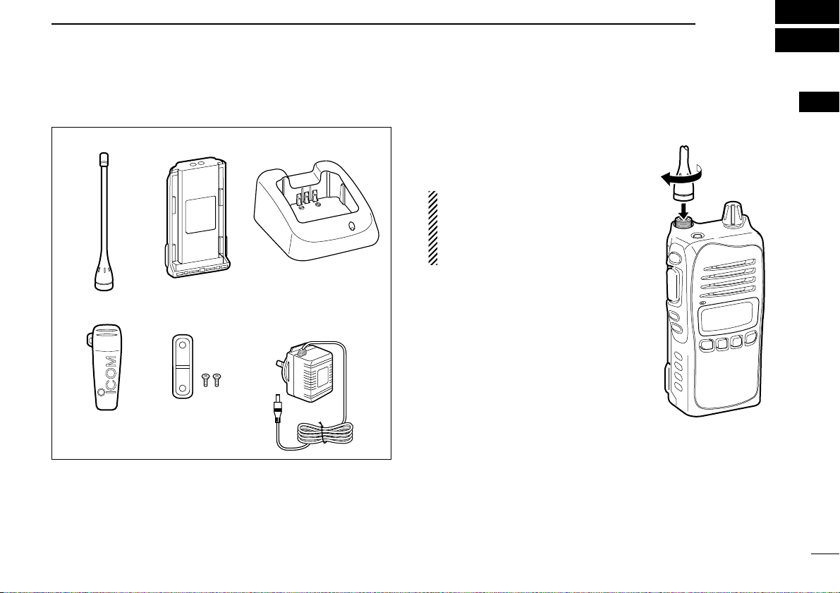
■ Supplied accessories ■ Accessory attachments
DFlexible antenna
Connect the supplied flexible antenna to the antenna connector.
CAUTION!
• NEVER HOLD the antenna
when carrying the transceiver.
• Transmitting without an antenna
may damage the transceiver.
Belt clip Jack cover
(with screws)
AC adapter
(for the battery charger)
Battery chargerBattery pack
Flexible antenna
Page 6
2
1
ACCESSORIES
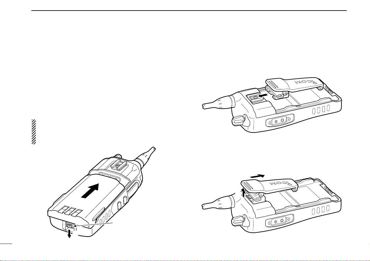
ïBattery pack
To attach the battery pack:
Slide the battery pack in the direction of the arrow (q), then
lock it with the battery release button.
• Slide the battery pack until the battery release button makes a ‘click’
sound.
To release the battery pack:
Push the battery release button in the direction of the arrow
(w). Then slide the battery pack in the direction opposite to
the arrow (q).
NEVER release or attach the battery pack when the transceiver is wet or soiled. This may result water or dust getting into the transceiver/battery pack and may result in the
transceiver being damaged.
DBelt clip
To attach the belt clip:
q Release the battery pack if it is attached.
w Slide the belt clip in the direction of the arrow until the belt
clip is locked and makes a ‘click’ sound.
To detach the belt clip:
q Release the battery pack if it is attached.
w Pinch to lift the clip (q), and slide the belt clip in the direc-
tion of the arrow (w).
q
w
q
w
Battery release button
Page 7
3
1
ACCESSORIES
1
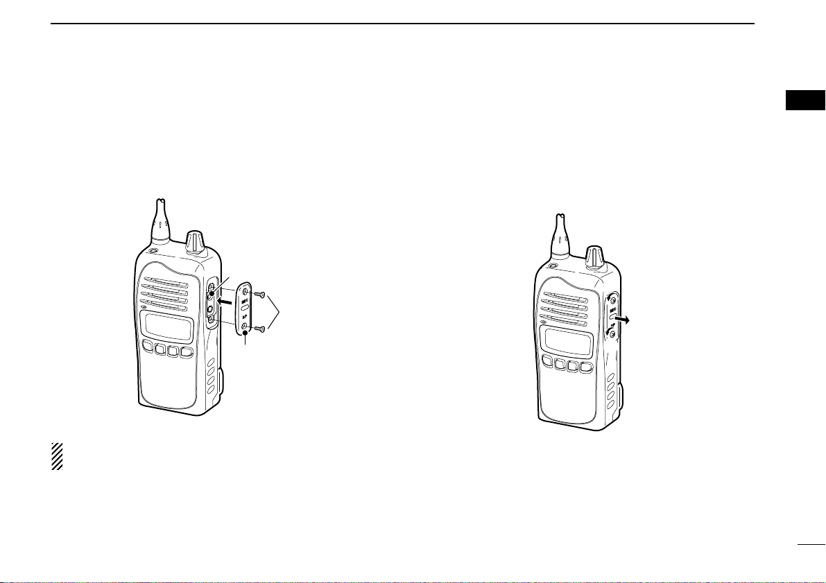
ïJack cover
Attach the jack cover when the optional speaker-microphone
or headset is not used.
To attach the jack cover:
q Attach the jack cover to the [MIC/SP] jack.
w Tighten the screws using a Phillips screwdriver.
CAUTION!
Use the supplied screws only.
To detach the jack cover:
q Unscrew the screws using a Phillips screwdriver.
w Detach the jack cover for the optional speaker-microphone
or headset connection.
q
q
w
q
w
[MIC/SP] jack
Jack cover
Page 8
4
2
PANEL DESCRIPTION
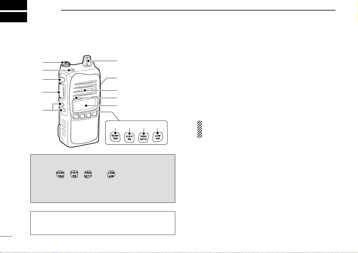
■ Front panel
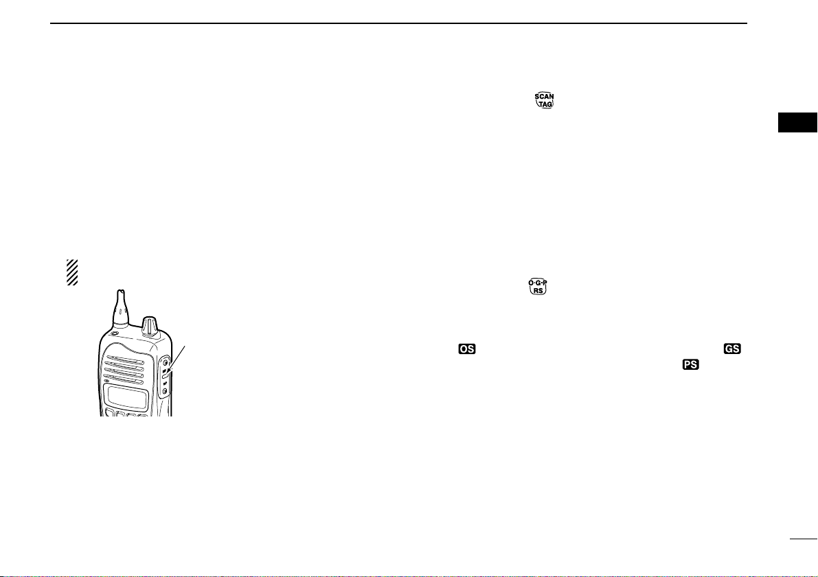
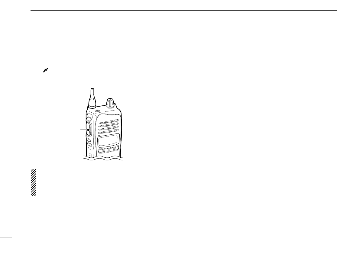
q ANTENNA CONNECTOR
Connects the supplied antenna.
w TOP KEY* [Top]
NN
NN
(Function/Set Mode)
➥ Push to turn Function mode ON.
• “F” appears when Function mode is turned ON.
➥ Push and hold for 2 sec. to enter Set mode. (p. 34)
FF
FF
(Function/RX VFO)
➥ Push to turn the Function mode OFF.
• “F” disappears when Function mode is turned OFF.
➥ Push and hold for 2 sec. to enter RX VFO mode.
(RX channel ‘RX-XX’ operation only) (p. 31)
NOTE: Returns to the Normal mode automatically after
30 sec. when no key operation is performed in Function
or Set mode.
e SIDE1 KEY* [Side1]
NN
NN
(Monitor/TSQL)
➥ Push to toggle the monitor function ON or OFF. (p. 14)
➥ Push and hold for 2 sec. to activate the following func-
tions in order.
• Subaudible tone encoder and Tone squelch/DTCS
squelch (“T SQL” appears) (p. 23)
• Pocket beep (“T SQL ë” appears) (p. 24)
• No tone operation (“T SQL ë” disappears)
FF
FF
(SQL/ATS)
➥ Push to enter the squelch level setting mode, then push
[CH Up] or [CH Down] to set the squelch level. (p. 14)
➥ Push and hold for 2 sec. to turn the ATS (automatic
transponder system) function ON or OFF. (p. 30)
NN
NN
: Stands for Normal mode operation.
FF
FF
: Stands for Function mode operation. (Push [Top]
(Function) to enter Function mode.)
Information: Up to four desired functions, one each for
Normal and Function mode, can be re-assigned to [Top],
[Side1], , , and keys with the optional
CS-41S
CLONING SOFTWARE
. (p. 8)
The default setting is used in this instruction manual, for
description.
q
w
e
r
t
y
u
Speaker
Microphone
i
o!0 !1 !2
Page 9
5
2
PANEL DESCRIPTION
2
r PTT SWITCH [PTT] (p. 12)
Push and hold to transmit; release to receive.
t CH UP/CH DOWN KEYS [CH UP]/[CH DOWN]
Push to select an operating channel, set mode setting, etc.
(pgs. 11, 34)
y VOLUME CONTROL [VOL] (pgs. 10, 11)
Rotate to turn the power ON/OFF and adjusts the audio
level.
u EXTERNAL MICROPHONE/SPEAKER JACK
Connect an optional speaker-microphone or headset.
NOTE: Connect or disconnect the optional equipment
after the transceiver is turned OFF.
i FUNCTION DISPLAY (p. 6)
Displays a variety of information such as an operating
channel number/name, SelCall code, selected function, etc.
o SCAN/TAG KEY*
NN
NN
(Scan/Scan Tag)
➥ Push to start or stop the scan. (pgs. 19, 20)
➥ Push and hold for 2 sec. to set or clear the displayed
channel as a TAG (scanned) channel. (p. 18)
• “S” appears when the selected channel is tagged.
FF
FF
(TX Code CH/Call)
➥ Push to enter the SelCall TX code channel selection
mode, then push [CH Up] or [CH Down] to select. (CB
channel operation only) (p. 25)
➥ Push and hold for 2 sec. to transmit to the SelCall TX
code channel. (CB channel operation only) (p. 27)
!0 O•G•P/RS KEY*
NN
NN
(Scan Mode/Rpt Scan)
➥ Push to select the scan type from open scan, group
scan and priority scan in order. (p. 18)
• “”appears when the open scan is selected, “”
appears when the group scan is selected, and “”appears
when the priority scan is selected.
➥ Push and hold for 2 sec. to start the repeater scan. (p. 21)
• Repeater output channel ‘CB-R1’ to ‘CB-R8’ operation only
FF
FF
(Quiet/ID-MR)
➥ Push to toggle the quiet function ON or OFF. (CB chan-
nel ‘CB-XX’ operation only) (p. 29)
• “Q” appears when the quiet function is turned ON.
➥ Push and hold for 2 sec. to enter the received ID code
history indication mode. (p. 28)
• “NO ID” is displayed when no ID code is memorized.
Jack cover
NOTE: Attach the jack cover when
the optional equipment is not used.
See (p. 3) for details.
Page 10
6
2
PANEL DESCRIPTION
!1 PRIO/SET•P KEY*
NN
NN
(PRIO/PRIO Set)
➥ Push to select the priority channel. (p. 13)
➥ Push and hold for 2 sec. to set the displayed channel as
the priority channel. (p. 13)
FF
FF
(S-Ring/PRIO Clear)
➥ Push to transmit the Smart-Ring signal. (p. 30)
• When RX channel is selected, “N/A” appears.
➥ Push and hold for 2 sec. to cancel the priority channel
setting. (p. 13)
!2 LOW/“”KEY*
NN
NN
(RF Power/Lock)
➥ Push to toggle the transmit output power level. (p. 11)
➥ Push and hold for 2 sec. to electronically lock all keys
except the following (p. 14):
[PTT], [Side1] (Monitor), [Top] (Function), (Call)
and (Lock)
Push and hold for 2 sec. again to turn the lock function
OFF.
FF
FF
(Dup/Zone)
➥ Push to toggle the selected channel between duplex or
simplex operation. (Depending on pre-setting)
• Duplex operation can be selected in ‘CB-R1’ to ‘CB-R8’ only.
➥ Push and hold for 2 sec., then select the desired zone
with [CH Up] or [CH Down]. (p. 11)
• Available only when more than two zones are set.
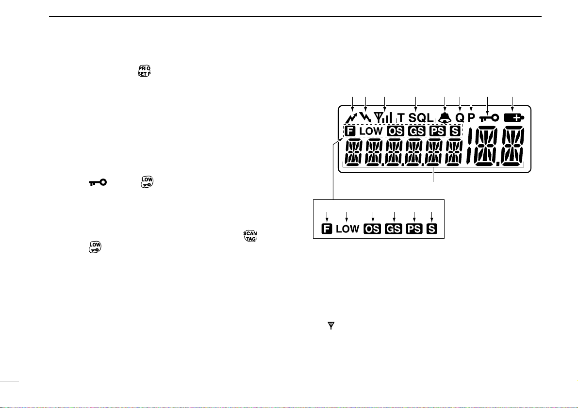
■ Function display
q TRANSMIT INDICATOR
Appears while transmitting.
w BUSY INDICATOR
Appears while the channel is busy.
e SIGNAL STRENGTH INDICATOR
Indicates relative signal strength level.
• “”blinks when the ATS function is in use. (p. 30)
r TONE INDICATORS (p. 23)
➥ “T” appears while the Subaudible tone encoder is in use.
➥ “T SQL” appears while the Tone squelch/DTCS squelch
function is in use.
q w r oiuye
!0
!1 !4 !5 !6!3!2
t
Page 11

7
2
PANEL DESCRIPTION
2
t BELL INDICATOR
➥ Appears when the pocket beep function is in use. (p. 24)
➥ Blinks when the specified SelCall or Smart Ring call is
received. (pgs. 28, 30)
y QUIET INDICATOR (p. 29)
Appears when the Quiet function is ON (SelCall mute is
activated.)
u PRIORITY CHANNEL INDICATOR (p. 13)
Appears when the priority channel is set.
i KEY LOCK INDICATOR (p. 14)
Appears during the key lock function is ON.
o BATTERY INDICATOR
Appears or blinks when the battery capacity decreases to
a specified level.
!0 ALPHANUMERIC DISPLAY
The operating channel number, channel name, Set mode
contents etc. is displayed.
!1 FUNCTION INDICATOR
Appears during the Function mode is ON.
• A secondary function of the key can be access.
!2 LOW POWER INDICATOR (p. 11)
Appears when low output power or dry battery mode is
selected.
• When the battery power decreases to a specified level, low
power is selected automatically.
!3 OPEN SCAN INDICATOR (p. 19)
Appears when the ‘Open scan’ is selected.
!4 GROUP SCAN INDICATOR (p. 20)
Appears when the ‘Group scan’ is selected.
!5 PRIORITY SCAN INDICATOR (p. 20)
Appears when the ‘Priority scan’ is selected.
!6 SCAN CHANNEL INDICATOR
Appears when the selected channel is specified as a tag
(scanned) channel.
Information:
“N/A” appears when the pushed key is not available.
Page 12

8
2
PANEL DESCRIPTION
■ Programmable function keys
The following functions can be assigned to [Top], [Side1],
, , and programmable function keys with
the optional CS-41S
CLONING SOFTWARE
.
The key function activates after pushing [Function] when the
programmable function key is assigned to the function mode
operation.
If the programmable function names are bracketed in the following explanations, the specific key is used to activate the
function depends on the programming.
Scan/Scan Tag
➥ Push to start/stop the scan.
➥ Push and hold for 2 sec. to set or clear the displayed chan-
nel as a TAG channel.
Scan Mode/Rpt Scan
➥ Push to select the scan mode.
➥ Push and hold for 2 sec. to start repeater scan.
PRIO/PRIO Set
➥ Push to select the priority channel.
➥ Push and hold for 2 sec. to set the displayed channel as
the priority channel.
S-Ring/PRIO Clear
➥ Push to transmit the Smart-Ring call.
• When RX channel is selected, “N/A” appears.
➥ Push and hold for 2 sec. to cancel the priority channel set-
ting.
Monitor/TSQL
(This key function can be assigned in the Normal mode only.)
➥ Push to toggle the monitor function ON or OFF.
➥ Push and hold for 2 sec. to activate the following functions
in order.
• Subaudible tone encoder and Tone squelch/DTCS squelch
• Pocket beep
• No tone operation.
RF Power/Lock
➥ Push to toggle the transmit output power level.
➥ Push and hold for 2 sec. to toggle key lock function ON and
OFF.
TX Code CH/Call
➥ Push to enter the TX code channel selection mode, then
push [CH Up] or [CH Down] to select the desired channel
(CB channel operation only).
➥ Push and hold for 2 sec. to transmit the specified SelCall
TX code in the selected channel (CB channel operation
only).
Page 13

9
2
PANEL DESCRIPTION
2
Quiet/ID-MR
➥ Push to quiet function ON or OFF (CB channel operation
only).
➥ Push and hold for 2 sec. to enter the received ID code his-
tory indication mode.
SQL/ATS
➥ Push to enter the squelch level setting mode, then push
[CH Up] or [CH Down] to set the squelch level.
➥ Push and hold for 2 sec. to turn the ATS (Automatic
Transponder System) function ON and OFF.
Dup/Zone
➥ Push to set the selected channel as Duplex or Simplex
operation.
• Duplex channel can be selected in ‘CB-R1’ to ‘CB-R8’ only.
➥ Push and hold this key for 2 sec. then push [CH Up] or
[CH Down] to select the desired zone. (Available only
when more than two zones are set.)
Function/Set Mode
(This key function can be assigned to the [Top] key only.)
➥ Push to turn Function mode ON or OFF.
➥ Push and hold for 2 sec. to the Set mode ON or OFF.
• After entering the Set mode, push this key momentarily to select
the item, and push [CH Up] or [CH Down] to change the setting.
Function/RX VFO
(This key function can be assigned to the [Top] key only.)
➥ Push to turn Function mode ON or OFF.
➥ Push and hold for 2 sec. to enter the RX VFO mode.
In RX VFO mode, the operating frequency and the channel
spacing setting can be changed.
SQL/Set Mode
(This key function can be assigned to the [Top] key only.)
➥ Push to enter the squelch level setting mode, then push
[CH Up] or [CH Down] to set the squelch level.
➥ Push and hold for 2 sec. to the Set mode ON or OFF.
• After entering the Set mode, push this key momentarily to select
the item, and push [CH Up] or [CH Down] to change the setting.
Page 14
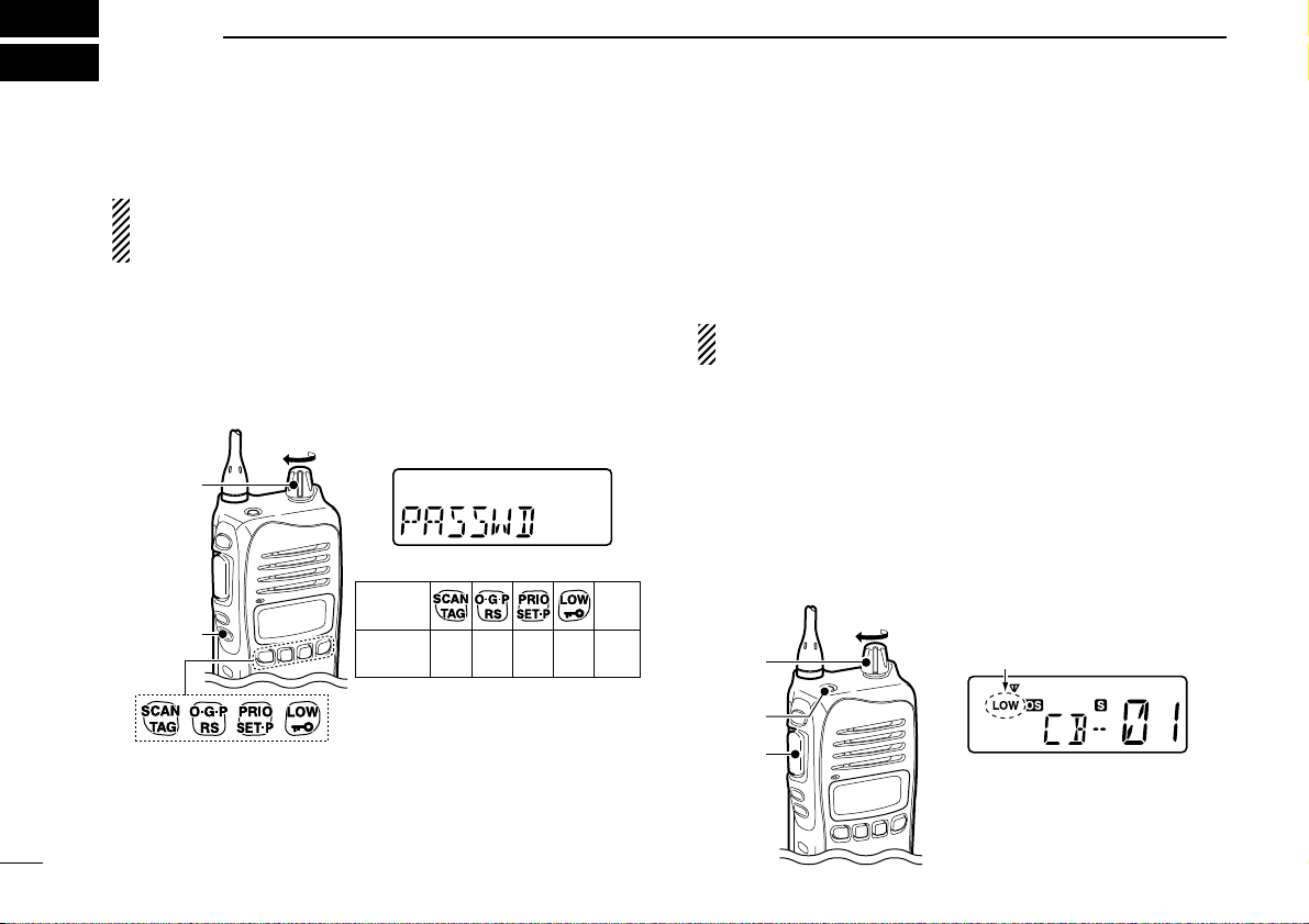
■ Turning power ON
Prior to using the transceiver for the first time, the battery
pack must be fully charged for optimum life and operation.
(p. 39)
q Rotate [VOL] to turn the power ON.
w If the transceiver is programmed for a start up password,
input the digit codes as directed by your dealer.
• The keys in the table below can be used for password input:
• The transceiver detects numbers in the same block as identical.
Therefore “01234” and “56789” are the same.
e When the “PASSWD” indication does not clear after
inputting 4 digits, the input code number may be incorrect.
Turn the power off and start over in this case.
DBattery type selection
The battery type MUST be selected according to the type of
battery attached when turning the transceiver ON.
Ask your dealer for details.
NOTE: When the selected battery type is not matched to
the attached battery, the transceiver does not work correctly.
q Turn the power OFF in advance.
w While pushing and holding [Top] and [PTT], rotating [VOL]
to turn power ON to toggle the attaching battery type.
• After the display appears, release [Top] and [PTT].
• “DRY” is displayed for about 3 sec. then “LOW” appears when
the Alkaline battery operation is selected. In this case, the transmit output power is low.
• “LI-ION” is displayed for about 3 sec. when the Lithium-ion battery operation is selected.
[VOL]
[PTT]
[Top]
Appears
Alkaline battery operation
(dry battery mode) is selected.
KEY
NUMBER
0
5
4
9
3
8
2
7
1
6
[CH Down]
CH
Down
[VOL]
10
3
BASIC OPERATION
Page 15
11
3
BASIC OPERATION
3
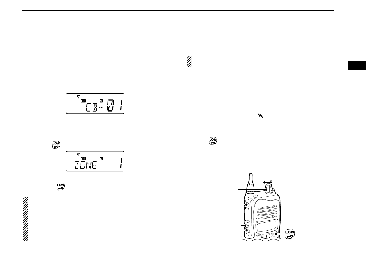
■ Channel selection
➥ Push [CH Up] or [CH Down] to select the desired channel.
• While pushing and holding [CH Up] or [CH Down], the displayed
channel changes continuously until channel 1 is selected.
• When channel 1 is selected, beeps are emitted.
• ‘CB-XX’ appears when the CB channel is selected and ‘RX-XX’
appears when the RX channel is selected.
DZone type selection
(Available only when more than two zones are set.)
q Push [Top]
(Function) to enter the function mode, and push
and hold
(Zone) for 2 sec. to enter the zone select mode.
w Push [CH Up] or [CH Down] to select the desired zone,
then push
(Zone) again to set.
NOTE:
• The selected channel is retained even when the transceiver is turned off.
• ‘CB-05,’‘CB-R5’ and ‘CB-35’ channels are used for the
emergency. And ‘CB-22’ and ‘CB-23’ channels are used
for telemetry and telecommand applications, so the voice
communications are not available on these channels.
■ Receiving and transmitting
NOTE: Transmitting without an antenna may damage the
transceiver. See page 1 for accessory attachments.
Receiving:
q Rotate [VOL] to turn the power ON.
• If “T SQL” appears on the display, push and hold [Side1] for 2
sec. once or twice to cancel the tone squelch or pocket beep.
(pgs. 23, 24)
w Select the desired operating channel as at left.
• When receiving a signal, “” appears and audio is emitted
from the speaker.
• Further adjustment of [VOL] may be necessary at this point.
• Push [Side1] to toggle the monitor function ON and OFF.
e Push (RF Power) to select the output power if neces-
sary.
• “LOW” appears when low power is selected.
• Choose low power to conserve battery power, choose high
power for longer distance communications.
[VOL]
[Side1]
[CH UP]/
[CH Down]
Page 16
12
3
BASIC OPERATION
Transmitting:
Wait for the channel to become clear to avoid interference.
q While pushing and holding [PTT], speak into the micro-
phone at a normal voice level.
• “” appears.
• A PTT hold function is available. See p. 33 for details.
w Release [PTT] to return to receive.
IMPORTANT: To maximize the readability of your signal;
1. Pause briefly after pushing [PTT].
2. Hold the microphone 5 to 10 cm from your lips, then
speak into the microphone at a normal voice level.
DTransmitting notes
• Transmit inhibit function
The transceiver has several inhibit functions which restrict
transmission under the following conditions:
- The channel is busy or un-matched CTCSS/DTCS is
received. (Depending on the transmission lockout function
setting.)
- The selected channel is a ‘receive only’ channel.
• Time-out timer
After continuous transmission for the pre-programmed time
period, the time-out timer is activated, causing the transceiver to stop transmitting.
• Penalty timer
Once the time-out timer and lockout is activated, transmission
is further inhibited for a period determined by the penalty
timer.
[PTT]
Page 17
13
3
BASIC OPERATION
3
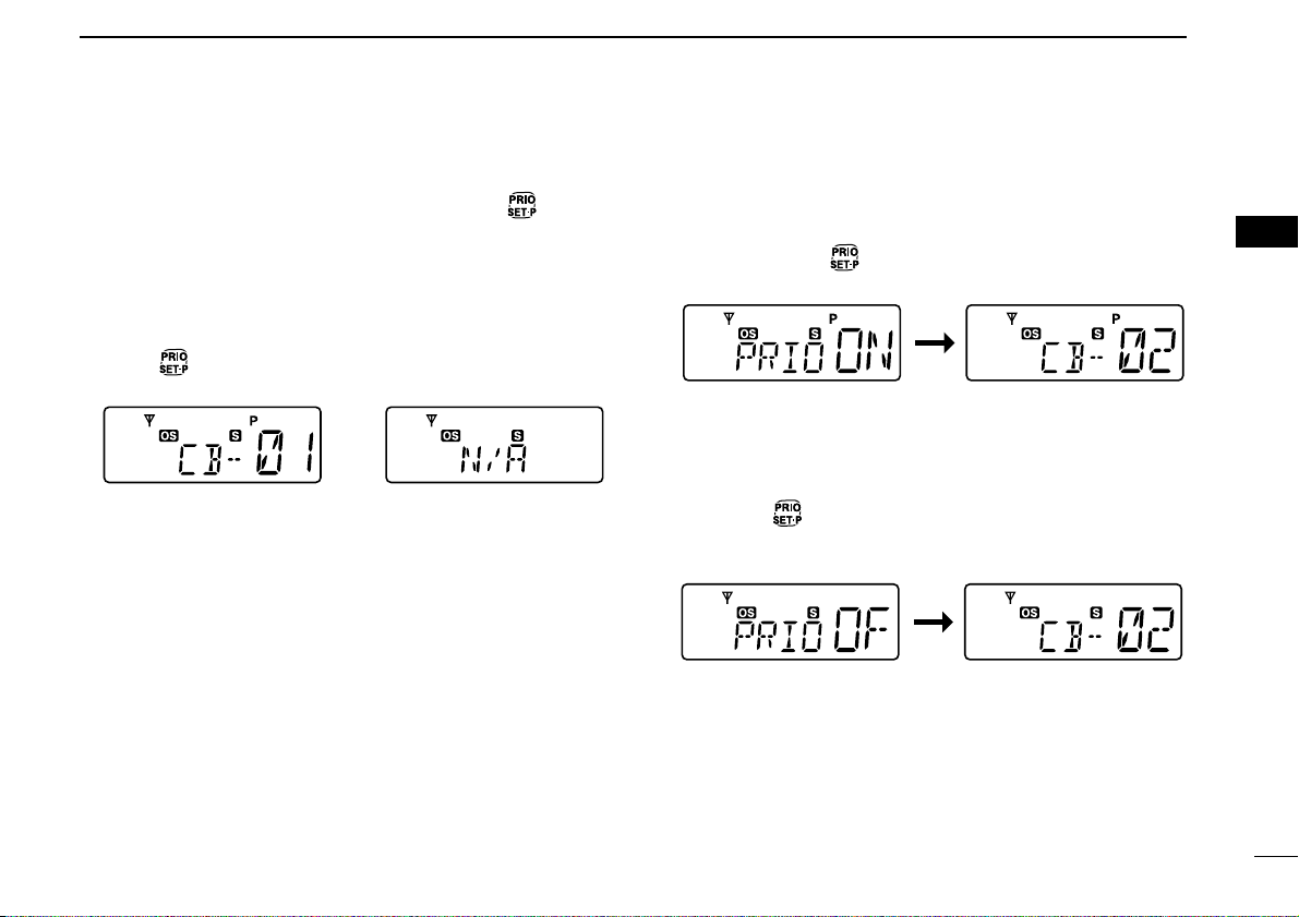
■ Priority channel setting
The priority channel, simply recalled by pushing (PRIO),
and also is automatically monitored during the priority scan.
You can set the only one channel as the priority channel.
“P” appears when the priority channel is set.
DThe priority channel selection
➥ Push (PRIO) to select the priority channel.
• “N/A” appears when the priority channel is not set.
DSet the priority channel
q Select the desired channel. (p. 11)
w Push and hold
(PRIO Set) for 2 sec. to set the dis-
played channel as the priority channel.
DCancel the priority channel setting
➥ Push [Top] (Function) to enter the function mode, then push
and hold
(PRIO Clear) for 2 sec. to cancel the priority
channel setting.
• “P” disappears.
The priority channel
is cancelled.
The selected channel is set
to the priority channel.
The priority channel
is selected.
When the priority
channel is not set.
Page 18

14
3
BASIC OPERATION
■ Monitor function
This function is used to listen to weak signal or to open the
tone squelch manually.
➥ Push [Side1] (Monitor) to toggle the monitor function ON
and OFF.
• “”blinks when the monitor function is in use.
■ Lock function
This function electronically locks all keys except for [PTT],
[Side1]
(Monitor), [Top] (Function), (Call) and (Lock)
to prevent accidental channel changes and function access.
➥ Push and hold
(Lock) for 2 sec. to toggle the lock func-
tion ON and OFF.
• “”appears when the lock function is in use.
■ Adjusting the squelch level
In order to receive signals properly, the squelch must be
adjusted to the proper level.
q Push [Top] (Function) to enter the function mode, then push
[Side1]
(SQL) to enter the squelch level setting mode.
w Push [CH Up] or [CH Down] to adjust the squelch level
within 0 to 9 ranges.
e Push [Side1]
(SQL) to exit the squelch level setting mode.
The squelch level
is indicated.
Appears
Blinks
Page 19

15
3
BASIC OPERATION
3
■ Display backlighting
The transceiver has display backlight for night-time operation.
q Push and hold [Top]
(Set Mode) for 2 sec. to enter set
mode.
w Push [Top]* several times until “LIGHT” appears.
e Push [CH Up] or [CH Down] to select the display back-
light condition.
• ON : Backlight lights continuously.
• A2 : Lights for 5 sec. when any key except [PTT] is pushed, or
the LCD indication is changed.
• AT : Lights for 5 sec. when any key except [PTT] is pushed or
the Selcall signal is transmitted/received.
• OF : Backlight never lights.
r Rotate [VOL] to turn the power OFF, or push and hold
[Top]
(Set Mode) for 2 sec. to exit set mode.
*Regardless of the assigned key function.
■ Set mode
Set mode is accessed at power ON and allows you to set seldom-changed settings. In this case you can “customize” the
transceiver operation to suit your preferences and operating
style. See p. 34 for set mode items detail.
Entering the set mode:
q While pushing and holding [CH Up] and [CH Down],
rotate [VOL] to turn the power ON. Then, push and hold
[Top]
(Set Mode) for 2 sec. to enter set mode.
w Push [Top]* several times to select the appropriate item.
Then push [CH Up] or [CH Down] to set the desired level/
condition.
• Available set mode functions are SQL Level, CTCSS tone/
DTCS code, Auto power OFF, Backlight, Beep, Beep Level,
Mic Gain, Battery Voltage, Signal Moni, Power Save, TOT,
Lock-out, Scan Stop Timer, Scan Restart, Roger Beep and
Own ID.
e Rotate [VOL] to turn the power OFF, or push and hold
[Top]
(Set Mode) for 2 sec. to exit set mode.
NOTE: Set mode can be accessed via the [Top]
(Set Mode)
key operation only (p. 34.) In this case, set mode allows
quicker item selection. Set “Enable” to the most often used
items with the CS-41S
CLONING SOFTWARE
.
*Regardless of the assigned key function.
[
Page 20

16
4
REPEATER OPERATION
■ Repeater operation
Repeaters allow you to extend the operational range of your
radio.
Normally, a repeater has independent frequencies for receive
and transmit.
■ Accessing a repeater
A repeater amplifies received signals and re-transmits them
on a different frequency, allowing you to communicate over
greater distances with improved reliability. When using a
repeater, the repeater output channel (‘CB-R1’ to ‘CB-R8’)
must be selected.
You can search the accessible repeater in your local area
using the Repeater search scan function (p. 21).
q Select the desired repeater output channel (‘CB-R1’ to
‘CB-R8’). (p. 11)
w While pushing and holding [PTT], speak into the micro-
phone at your normal voice level.
• “” appears.
e Release [PTT] to receive.
Appears
Station BStation A
Repeater
476.4250 MHz
477.1750 MHz
477.1750 MHz
476.4250 MHz
Uplink
(transmitting freq.)
Downlink
(receiving freq.)
Page 21

17
5
SCAN OPERATION
4
5
■ Scan types
The transceiver has 4 scan types, tag function and 4 resume
conditions providing scanning versatility.
Tag channels are independently set for open, group and priority scans. Initially, all channels may be set as tag channels
for all scans.
CB-R2
CB-R2CB-R1
Scan cancel
CB-R8
CB-R1
CB-R3CB-R4
CB-R8
REPEATER SEARCH SCAN
Scans all repeater channels (‘CB-R1’ to ‘CB-R8’) in sequence. If there are no busy channels after scanning
channels ‘CB-R1’ to ‘CB-R8,’ it begins scanning from
‘CB-R1’ again, then the transceiver transmits a signal to
search for a repeater while the scanning.
OPEN SCAN
ch 1 ch 2 ch 3
ch 40
ch 6ch 39
ch 4
ch 5
Repeatedly scans all tag channels in sequence.
GROUP OR PRIORITY SCAN
ch 1
ch 10
ch 9 ch 8 ch 7
Priority
channel
ch 2 ch 3 ch 4
Repeatedly watches a designated priority channel
after scanning 5 tagged channels.
ch 5
ch 6
Page 22

18
5
SCAN OPERATION
■ Scanning preparation
IC-41S scans all tagged channels, and can be selected so
the scan resume condition is a pause or timer scan.
Therefore, these items must be set before starting a scan
(except the repeater search scan). These items must be set
for each scan type (open, group and priority) independently.
DScan type selection
➥ Push (Scan Mode) several times to select the desired
scan type.
• Open, group and priority scans are available.
• “OPEN”, “GROUP” or “PRIO” is displayed for 1 sec. when each
scan type is selected.
DTag channel setting
q Select the desired scan type. (See at left.)
w Select the desired channel. (p. 11)
e Push and hold
(Scan Tag) for 2 sec. to toggle the tag
channel setting ON and OFF.
• “S” appears when the tag setting is ON (The channel is set as a
scan channel).
To speed up scanning:
For open scan, cancel the tag channel setting to skip undesired channels such as usually busy channels.
For group scan, set only often-used channels as tag channels.
All memory channels may be set as tag channels by
default.
Appears
Push
Push
Open scan is selected.
Group scan is selected.
Priority scan is selected.
Appears
Appears
Appears
Push
Page 23

19
5
SCAN OPERATION
5
DSetting scan resume condition
q Push and hold [Top] (Set Mode) for 2 sec. to enter set
mode.
w Push [Top]* several times until “S-TIME” appears.
e Push [CH Up] or [CH Down] to select the scan resume
timer.
• 5 : Scan pauses for 5 sec. then resumes.
• 10 : Scan pauses for 10 sec. then resumes.
• 15 : Scan pauses for 15 sec. then resumes.
• P5: Scan pauses until the signal disappears, then
resumes 5 sec. after the signal disappears.
r Rotate [VOL] to turn the power OFF, or push and hold
[Top]
(Set Mode) for 2 sec. to exit set mode.
■ Open scan
Open scan searches for being transmitted signals automatically and makes it easier to locate new stations for contact or
listening purposes.
IMPORTANT!:
During open scan, transmission is inhibited except on a
busy channel.
q Push
(Scan Mode) several times to select the open
scan. (p. 18)
• “”appears.
w Push (Scan) to start the open scan.
t When receiving a signal, scan pauses and resumes
according to the selected scan resume condition. (p. 19)
y Push
(Scan) to cancel the scan.
Scan start channel
Blinks
Open scan is selected.
Appears
[
Page 24

20
5
SCAN OPERATION
■ Group and priority scans
Group and priority scans repeatedly watch a priority channel
while scanning specified channels. This is useful when waiting for a call on the priority channel or several specified channels.
Group and priority scans behave differently when transmitting. Group scan can only transmit on a busy channel, and
priority scan can only transmit on a priority channel or start
channel.
q Push
(Scan Mode) several times to select the group or
priority scan. (p. 18)
• “”appears when the group scan is selected, and “”ap-
pears when the priority scan is selected.
w Set the priority channel if desired when the priority scan
type is selected in step q. (p. 13)
• When the priority channel is not set, scan start channel is monitored during the priority scan.
e Push (Scan) to start the scan.
r When receiving a signal, the scan pauses and resumes
according to the selected scan resume condition. (p. 19)
t Push
(Scan) to cancel the scan.
Blinks
BlinksGroup scan starts.
Priority scan starts.
Priority channel
Scan start channel
Appears
Priority scan is selected.Group scan is selected.
Appears
Appears
Page 25

21
5
SCAN OPERATION
5
■ Repeater search scan
The repeater search scan is not only searching for a signal
on the repeater channels, but also access a repeater by
transmitting automatically in sequence.
Thus the repeater search scan function searches an available
repeater in the area even if the repeater is not in use.
The repeater search scan detects a signal on the repeater
output channels (CB-R1 to CB-R8) only. Therefore,
repeater availability cannot be guaranteed even the
repeater scan is stopped, because the scan will stop if any
activity is detected. (The scan is cancelled when receiving
a signal, such as stations communicating in simplex operation on a repeater output channel.)
q Select the desired repeater output channel (‘CB-R1’ to
‘CB-R8’), and push and hold
(Rpt Scan) for 2 sec. to
start the repeater search scan.
• See the flow as described at right for repeater search scan details.
w When receiving a signal on the repeater channel, scan
stops.
• During second cycle scanning, 3 high beeps sound when receiving a signal, and 3 low beeps sound when no signal receiving.
e Push (Scan Mode) to cancel the scan manually.
• During transmitting, the repeater scan cannot be cancelled.
DD
Repeater search scan flow
Scan
Scan
Searches for signal on the repeater
output channels.
Access to the repeater
automatically. (0.5 sec.)
Wait for a signal from
the repeater. (0.5 sec.)
Access to the next repeater automatically.
(When not reply signal is received.)
Scan is cancelled automatically.
Scan start
channel
Appears
Appears
Blinks
Page 26

22
6
TONE SQUELCH OPERATION
■ Tone squelch operation
The transceiver is equipped with 51 CTCSS tone frequencies,
104 DTCS codes. CTCSS/DTCS operation provides communication with silent standby since you will only receive calls
from group members using the same CTCSS tone frequency/DTCS code.
NOTE: Channels 5 and 35 are used for the emergency
channels, and CTCSS/DTCS operation is not available on
these channels.
DSetting CTCSS tone frequency/
DTCS code
q Select the desired channel except for channels 5 and 35.
(p. 11)
w Push and hold [Top]
(Set Mode) for 2 sec. to enter set
mode.
e Push [Top] several times until “C” appears.
r Push to toggle the CTCSS tone frequency/DTCS
code setting mode.
t Push [CH Up] or [CH Down] to set the desired CTCSS
tone frequency/DTCS code.
y Rotate [VOL] to turn the power OFF, or push and hold
[Top]
(Set Mode) for 2 sec. to exit set mode.
• Available CTCSS tone frequency list (Hz)
NOTE: The transceiver has 51 tone frequencies and con-
sequently their spacing is narrow compared with units having 38 tones. Therefore, some tone frequencies may
receive interference from adjacent tone frequencies.
Freq.
67.0
69.3
71.0
71.9
74.4
77.0
79.7
82.5
85.4
88.5
91.5
No.
01
02
03
04
05
06
07
08
09
10
11
Freq.
94.8
97.4
100.0
103.5
107.2
110.9
114.8
118.8
123.0
127.3
131.8
No.
12
13
14
15
16
17
18
19
20
21
22
Freq.
136.5
141.3
146.2
151.4
156.7
159.8
162.2
165.5
167.9
171.3
173.8
No.
23
24
25
26
27
28
29
30
31
32
33
Freq.
177.3
179.9
183.5
186.2
189.9
192.8
196.6
199.5
203.5
206.5
210.7
No.
34
35
36
37
38
39
40
41
42
43
44
Freq.
218.1
225.7
229.1
233.6
241.8
250.3
254.1
No.
45
46
47
48
49
50
51
CTCSS tone setting mode DTCS code setting mode
DTCS code
CTCSS tone freqnency
List number
(grey line)
List number
(grey line)
[
Page 27

23
6
TONE SQUELCH OPERATION
6
• Available DTCS code list DTurning ON the tone squelch operation
q Select the desired channel except for channels 5 and 35.
(p. 11)
w Set the desired CTCSS tone frequency/DTCS code in set
mode. (See at left page)
e Push and hold [Side1]
(TSQL) for 2 sec. several times until
“T SQL” appears.
r When the received signal includes a matching tone or
code, squelch opens and the signal can be heard.
• When the received signal is not matched, tone squelch does not
open, however, “”appears.
• To open the squelch manually, push [Side1].
t Operate the transceiver in the normal way.
y To cancel the tone squelch operation, push and hold
[Side1]
(TSQL) for 2 sec. several times until “T SQL” dis-
appears.
NOTE: CTCSS tone frequency/DTCS code and tone
squelch ON/OFF settings are automatically stored in memory channels for easy recall.
Appears
Code
023
025
026
031
032
036
043
047
051
053
054
065
071
072
073
074
114
115
116
122
125
No.
01
02
03
04
05
06
07
08
09
10
11
12
13
14
15
16
17
18
19
20
21
Code
131
132
134
143
145
152
155
156
162
165
172
174
205
212
223
225
226
243
244
245
246
No.
22
23
24
25
26
27
28
29
30
31
32
33
34
35
36
37
38
39
40
41
42
Code
251
252
255
261
263
265
266
271
274
306
311
315
325
331
332
343
346
351
356
364
365
No.
43
44
45
46
47
48
49
50
51
52
53
54
55
56
57
58
59
60
61
62
63
Code
371
411
412
413
423
431
432
445
446
452
454
455
462
464
465
466
503
506
516
523
526
No.
64
65
66
67
68
69
70
71
72
73
74
75
76
77
78
79
80
81
82
83
84
Code
532
546
565
606
612
624
627
631
632
654
662
664
703
712
723
731
732
734
743
754
No.
85
86
87
88
89
90
91
92
93
94
95
96
97
98
99
100
101
102
103
104
Page 28

24
6
TONE SQUELCH OPERATION
■ Pocket beep operation
This function uses CTCSS (subaudible) tones and DTCS
code for calling and can be used as a “common pager” to
inform you that someone has called while you were away
from the transceiver.
D Waiting for a call from a specific station
q Select the desired channel except for channels 5 and 35.
(p. 11)
w Set the desired CTCSS tone/DTCS code in set mode.
(pgs. 22, 35)
e Push and hold [Side1]
(TSQL) for 2 sec. several times until
“T SQL ë” appears to activate the pocket beep.
r When the received signal includes a matching tone or
code, the transceiver emits beep tones every 10 sec. and
“ ë” blinks.
t Push [PTT] to answer and to stop blinking.
• Tone squelch is automatically selected.
Blinks
Page 29

25
7
SELCALL OPERATION
6
7
■ General
In addition to the tone squelch operation for silent stand-by,
the SelCall operation is available. SelCall is an abbreviation
for “Selective Calling.” In tone squelch operation, there are
155 ways to make an individual call with CTCSS tone frequencies/DTCS codes versus 100,000 ways to make an individual call with SelCall using 5tone.
SelCall allows you to selectively call another unit that is operating on the same channel.
SelCall can also call the entire group on that channel using
tone squelch code.
The caller station code/name, status message, Answer Back
function, automatic scan start function, etc. are available with
SelCall operation. A variety of functions are available depending on the setting with the CS-41S
CLONING SOFTWARE
. See
the help file for setting details.
NOTE:
• Channels 5 and 35 are used for the emergency channels,
and SelCall operation is not available on these channels.
• SelCall transmission is restricted for total of 3 sec. in a
minute. If your try to transmit over 3 sec., “N/A” appears
(when
(Call) is pushed,) or error beep is emitted
(when [PTT] is pushed.)
■ Calling operation
DTX code channel selection
(TX Code CH) enables you to change the TX code chan-
nel with [CH Up] or [CH Down].
TX code means the Transmitting SelCall code. Max. 32 TX
code channels can be pre-programmed into the transceiver using the optional CS-41S
CLONING SOFTWARE
.
To select a TX code channel:
q Select the desired CB channel (‘CB-XX’) except for chan-
nels 5 and 35. (p. 11)
w Push [Top]
(Function) to enter the function mode, then push
(TX Code CH) to enter the TX code channel selection
mode.
• The channel name is displayed instead of the TX code, if the
channel name is programmed.
e Push [CH Up] or [CH Down] to select the desired TX code
channel.
TX code
Page 30

26
7
SELCALL OPERATION
r Push [PTT] to transmit to the selected TX code channel,
or push
(TX Code CH) to set the selected TX code
channel and return to the stand-by mode.
✔
CONVENIENT!
The TX code channel name can be assigned to the all 32 TX
code channel via the optional CS-41S
CLONING SOFTWARE
.
The TX code channel name allows you to easy to select the
channel, find the channel user, and so on.
DTX code number edit
(TX Code CH) enables you to change the TX code con-
tents within the allowable digits.
The group call function works by allowing you to edit a special
‘group code’ into the last 2 digits position of the SelCall ID
code.
To edit a TX code:
q Select the desired CB channel (‘CB-XX’) except for chan-
nels 5 and 35. (p. 11)
w Push [Top]
(Function) to enter the function mode, then push
(TX Code CH) to enter the TX code channel selection
mode.
• Push [CH Up] or [CH Down] to select the desired TX code
channel, if desired.
e Push and hold (TX Code CH) for 2 sec. again to enter
the TX code edit mode.
r Push (TX Code CH) to select the desired digit to be
edited.
The editable digit starts blinking
Appears
Transmitting
Page 31

27
7
SELCALL OPERATION
7
t Push [CH Up] or [CH Down] to set the desired code.
• Select “❋” when group code is set.
y Push (TX Code CH) to set the digit and the editable
digit move to right automatically.
u Repeat step t and y to input all allowed digits.
i After setting the last digit, push
(TX Code CH) to set
the code and return to the TX code channel selection
mode.
o Push [PTT] to transmit to the selected TX code channel,
or push
(TX Code CH) to set the selected TX code
channel and return to the stand-by mode.
NOTE: The TX code editable digit can only be set/changed
with the optional CS-41S
CLONING SOFTWARE
.
DTransmitting an individual call
➥ Push [Top] (Function) to enter the function mode, then push
and hold
(Call) for 2 sec. to transmit.
Appears
Transmitting
Appears
Transmitting
Page 32

28
7
SELCALL OPERATION
■ When receiving a call
D Receiving an individual call
q When receiving an individual call (default setting);
• “PiRo” beeps sound.
• The received code channel name is displayed.
• “ë” and the displayed channel name blink, and the SelCall mute
is released when the quiet mode is activated.
w While pushing and holding [PTT], speak into the micro-
phone at a normal voice level.
NOTE: When the ID decode function is turned ON, the received ID code is displayed instead of the channel name,
and memorised into the transceiver. The ID decode function can be turned ON using the optional CS-41S
CLONING
SOFTWARE
.
• RX code means the Receiving SelCall code. Max. 8 RX
code channels can be pre-programmed into the transceiver using the CS-41S.
• You can set the transceiver’s condition when receiving an
individual call using the CS-41S. See the help file for setting details.
Recall the memorised RX code:
q Push [Top]
(Function) to enter the function mode, then push
and hold
(ID-MR) for 2 sec. to display the memorised
RX code.
w Push [CH Up] or [CH Down] to select the desired RX code.
e Push [Top]
(Function) to enter the function mode, then push
and hold
(Call) for 2 sec. to transmit the code on the
selected channel.
DReceiving a group call
q When receiving a group call (default setting);
• “PiPi” beep sounds.
• “ë” and “GROUP” blink, and the SelCall mute is released when
the quiet mode is activated.
w While pushing and holding [PTT], speak into the micro-
phone at a normal voice level.
You can set the transceiver’s condition when receiving a
group call with the CS-41S. See the help file for setting details.
Blink
Blink
Page 33

29
7
SELCALL OPERATION
7
■ The quiet mode operation
When the quiet mode operation is turned ON, the SelCall
mute is activated and allows the silent operation until receiving a SelCall.
➥ Push [Top]
(Function) to enter the function mode, then push
(Quiet) to toggle the quiet mode ON and OFF.
• “Q” appears when the quiet mode is in use.
To monitor the channel:
➥ Push [Side1]
(Monitor) to release the mute (audio is emit-
ted.)
• “”blinks when the monitor function is in use.
To enable SelCall mute:
➥ When “”blinks, push [Side1]
(Monitor) to mute the
channel.
• “”disappears.
NOTE: The unmute condition may automatically return to
the mute condition after a specified time period depending
on the pre-setting.
■ Stun function
When the specified ID, set as a killer ID, is received, the stun
function is activated. (PC programming is required.)
When the killer ID is received, the transceiver switches to the
password required condition. Entering of the password via the
keypad is necessary to operate the transceiver again in this
case. (p. 10)
Blinks
Appears
Page 34

30
8
OTHER FUNCTIONS
These functions have an answer back feature, and allow you
to confirmation of whether or not a call has reached the
receiving party even if the operator is temporarily away from
the transceiver. The Smart-Ring is for manual, and the ATS
is for automatic confirmation.
D Smart-Ring
q Set the same CTCSS tone frequency for all of the group
transceivers and turn the tone squelch ON. (pgs. 22, 34)
w Push [Top]
(Function) to enter the function mode, then push
(S-Ring) to send the Smart-Ring call.
• “”appears.
• When a member of a specific group answers a call, “ë” and
“FOUND” blink.
• When no answer back is received, the transceiver emits short
failure beep tones and “FAILD” appears.
e Push [PTT] to answer and to stop blinking.
NOTE: The Smart-Ring function is available only when the
called station has set the same CTCSS tone frequency
and the same operating channel as you.
NOTE:
• The setting at left is for the calling station only. A called
party automatically sends an answer back signal without
any pre-settings. All IC-41S’s operating on the same op-
erating channel will answer back to the call in the surroundings communications area.
• When RX channel is selected, “N/A” appears.
DAT S
q Push [Top] (Function) to enter the function mode, then push
and hold [Side1]
(ATS) for 2 sec. to turn the ATS function ON.
• When RX channel is selected, error beep is emitted.
• The transceiver starts to send a searching signal every 60 sec.
• “”appears and “”starts blinking on the display when the
function is activated.
• When the transceiver receives an answer back signal, “”stays
on the display until the next search transmit.
• If no reply is received, “”blinks until the next search transmit.
w Push [Top] (Function) to enter the function mode, then push
and hold [Side1]
(ATS) for 2 sec. to turn the ATS function
OFF.
Blinks Blinks
Appears If no reply is received
BlinkAppears
■ Smart-Ring and ATS (Automatic Transponder System)
Page 35

31
8
OTHER FUNCTIONS
8
■ RX frequency setting (for RX channels only)
The receive frequency in the RX channels can be re-programmed within 450 to 520 MHz frequency range depending
on the setting.
D RX channel setting
The RX channels does not appear on the LCD (default;
“Inhibit” setting) and you cannot select it. So the RX channels
should be set to “Enable” before programming the RX frequency.
q While pushing and holding
*
and
*
, turn power ON
to indicate all pre-programmed RX channels (including the
inhibited channels.)
w Select the desired channel with [CH Up] or [CH Down],
then push
*
to set the displayed channel “Enable.”
e Turn the power OFF, then ON.
• The “Enable” channels appear on the LCD, and can be selected
with [CH Up]/[CH Down].
DRX frequency programming
q Select the desired RX channel (‘RX-XX’). (See at left)
w Push [Top]
(Function) to enter the function mode, then push
and hold [Top]
(RX VFO) for 2 sec. to enter the RX VFO
mode.
• Push
*
to toggle the bandwidth between wide or narrow.
e Push [CH Up] or [CH Down] several times to select the
desired frequency.
• The frequency changes according to the Wide/Narrow setting.
(p. 33)
*Regardless of the assigned key function.
Narrow channel spacing
(12.5 kHz steps)
Wide channel spacing
(25 kHz steps)
RX VFO modeRX channel
(in function mode)
*Appears when Narrow
channel spacing is set.
“Enable” setting“Inhibit” setting
Page 36

32
8
OTHER FUNCTIONS
r Push
*
to select the desired digit to be edited.
t Set the desired digit via [CH Up] or [CH Down].
y Push
*
to set the digit and the editable digit move to
right automatically.
u Repeat steps t and y to input the desired frequency.
i Push and hold [Top]* for 2 sec. to return to the normal
operation condition.
• RX frequency setting is memorized to the channel.
• Pushing [Top]* also returns to the normal operation condition. In
this case, the RX frequency setting is not memorized to the
channel. (temporary operation)
*Regardless of the assigned key function.
Page 37

33
8
OTHER FUNCTIONS
8
■ Wide/Narrow function
This function temporarily/permanently changes the bandwidth
between wide or narrow on the RX channel only.
q Select the desired RX channel. (p. 31)
w Enter the RX VFO mode. (p. 31)
e Push
*
to toggle the bandwidth between wide or nar-
row.
r Push and hold [Top]* for 2 sec. to return to the normal
operation condition.
• The bandwidth setting is memorized to the channel.
• Pushing [Top]* also returns to the normal operation condition. In
this case, the bandwidth setting is not memorized to the channel.
(temporary operation)
*Regardless of the assigned key function.
■ PTT hold function
The PTT switch can be operated as a one-touch PTT switch
(each push toggles between transmit/receive). Using this
function you can transmit without pushing and holding the
PTT switch.
To prevent accidental, continuous transmission with this function, the time-out timer function is automatically set to the
transceiver. See p. 12 for details.
q Turn the power OFF.
w While pushing and holding [PTT], rotate [VOL] to turn
power ON to turn the PTT hold function ON.
• “P-HOLD ON” is displayed for 1 sec.
e Push [PTT] to transmit and push again to receive.
• “” appears while transmitting.
r Repeat steps q and w to turn the PTT hold function OFF.
NOTE for the optional microphone operation:
This function does not activate when the PTT switch on the
optional microphone is pushed. And even if the transceiver
transmits with this function, the PTT switch on the optional
microphone must be pushed to speak.
Narrow channel spacing is selected
Wide channel spacing is selected
Page 38

34
9
SET MODE
■ Set mode
Set mode allows you to change seldom used common setting for the transceiver, or individual setting for the operating
channel. In this case you can “customize” transceiver operation to suit your preferences and operating style.
Available functions may differ depending on the pre-setting
via the optional CS-41S
CLONING SOFTWARE
.
NOTE: Set mode can be accessed via the [Top]
(Set Mode)
key operation after turning power ON with [CH Up] and [CH
Down] (p. 15.) In this case, all set mode items are available.
DSet mode operation
q Push and hold [Top] (Set Mode) for 2 sec. to enter Set mode.
• When no key is pushed for 30 sec. the transceiver returns to normal operation.
w Push [Top]* to select the desired item, if necessary.
e Push [CH Up] or [CH Down] to select the desired condi-
tion of the item.
r Rotate [VOL] to turn the power OFF, or push and hold
[Top]
(Set Mode) for 2 sec. to exit set mode.
*Regardless of the assigned key function.
• Own ID
• Lock-out • TOT • Power Save • Signal Moni • Battery Voltage
• Squelch Level • CTCSS/DTCS • Auto Power OFF • Backlight
• Mic Gain
• Beep Level
• Beep
• Roger Beep
• Scan Restart
• Scan Stop Timer
Starting item
: Push [Top]
D Set mode construction
Page 39

35
9
SET MODE
9
■ SET mode items
D Squelch level
Select the noise squelch threshold level within 0 to 9 ranges.
• There are 10 squelch levels to choose from 0 is completely open; 9
is tight squelch; 1 is loose squelch level.
D CTCSS tone frequency/DTCS code
Select the desired CTCSS tone frequency or DTCS code.
Pushing toggles the CTCSS/DTCS setting mode.
D Auto Power OFF
The transceiver can be set to automatically turn OFF after this
set period has passed when no key operation is performed.
• 0.5 to 4.0 hours (0.5 hours steps) and OFF can be specified.
DBacklight condition
The transceiver has display backlight for night-time operation.
ON : Backlight turns ON continuously.
A2
(Auto2) : Lights for 5 sec. when any key except [PTT] is
pushed, or the LCD indication is changed.
AT
(Auto) : Lights for 5 sec. when any key except [PTT] is
pushed or the SelCall signal is transmitted/
received.
OF
(OFF) : No backlight available.
DBeep tone
You can select silent operation by turning key-touch beep
tones OFF, or you can have confirmation beeps sound at the
push of a key by turning beep tones ON.
Beep tone ON (default) Beep tone OFF
Backlight Auto (default) Backlight ON
Auto power OFF
is OFF (default)
2.0 hours setting
CTCSS tone frequency
setting mode (default)
DTCS code setting mode
Push
Squelch level 2 (default) Squelch level 0 (“ ”appears)
Page 40

36
9
SET MODE
D Beep level
Set the key-touch beep output level from 1 to 5.
D Microphone gain level
Set the microphone gain level from 1 (Min) to 5 (Max).
D Battery voltage indicator
This function controls display or non-display settings of the
connected battery pack’s voltage when the power is ON.
• The voltage of the connected battery pack is displayed for 2 sec.
after power is turned ON.
DSignal Monitor function
This function controls the mute condition. The mute is released (audible) during SelCall code signal and roger beep
emission.
DAuto power save function
The auto power save function reduces current drain by deactivating the receiver circuit for preset interval.
This function will activate when no signal is received, and no
operation is performed for 5 sec.
Power save ON (default) Power save OFF
Signal monitor ON (default) Signal monitor OFF
Battery voltage
OFF (default)
Battery voltage ON
Mic gain level 3 (default) Mic gain level 1
Beep level 3 (default) Beep level 1
Page 41

37
9
SET MODE
9
D Time-Out timer (TOT)
The Time-Out Timer (TOT) function limits continuous transmission to prevent accidental prolonged transmission, etc.
This timer cuts a transmission OFF after 1 min. of continuous
transmission.
D Lockout function
Select the transmission lockout (temporary transmission
inhibit) capability.
RP
(Repeater Lockout) : Transmission is permitted only while
receiving a matched CTCSS tone, or
receiving no signal.
BU
(Busy Lockout)
: Transmission is inhibited while receiv-
ing a signal.
OF
(OFF) : No restriction for receiving a signal.
DScan resume timer
The scan resume condition can be set as a pause (P5) or
timer scan (15/10/5). When a signal disappears, scan
resumes after 5 sec. has passed regardless of the setting.
15/10/5 : Scan pauses for 15, 10 or 5 sec. when a signal is
detected, then resumes after that.
P5 : Scan pauses until the signal disappears and then
resumes after 5 sec.
DScan restart function
This function starts the scan after the transmission is performed during scan and 10 sec. has passed.
Scan restart timer
OFF (default)
Scan restart timer ON
Scan resume timer
P5 (default)
10 sec. setting
Lockout OFF (default) Repeater lockout setting
TOT OFF (default) TOT ON
Page 42

38
9
SET MODE
D Roger Beep
This function emits a beep on the communication party to inform the transmission is finished.
D Own ID
This function allows you to edit the Own ID.
To edit the Own ID:
q Push and hold [Top] (Set Mode) for 2 sec. to enter Set mode.
w Push [Top]* to select the “Own ID” item.
e Push and hold
*
for 2 sec. to enter the Own ID edit
mode.
r Push [CH Up] or [CH Down] several times to select the
desired digit.
t Push
*
to set the digit and the editable digit move to
right automatically.
y Repeat steps r and t to input the desired ID code.
u After setting the last digit, push
*
to set the Own ID
code.
*Regardless of the assigned key function.
Own ID ‘11111’
Roger beep OFF (default) Roger beep ON
Page 43

39
10
BATTERY CHARGING
9
10
■ Caution
R DANGER! Use and charge only specified Icom battery
packs with Icom radios or Icom charger. Only Icom battery
packs are tested and approved for use and charge with Icom
radios or Icom charger. Using third-party or counterfeit battery packs or charger may cause smoke, fire, or cause the
battery to burst.
DD
Battery caution
R DANGER! DO NOT hammer or otherwise impact the bat-
tery. Do not use the battery if it has been severely impacted or
dropped, or if the battery has been subjected to heavy pressure. Battery damage may not be visible on the outside of the
case. Even if the surface of the battery does not show cracks
or any other damage, the cells inside the battery may rupture
or catch fire.
R DANGER! NEVER use or leave battery packs in areas
with temperatures above +60˚C. High temperature buildup in
the battery, such as could occur near fires or stoves, inside a
sun heated car, or in direct sunlight may cause the battery to
rupture or catch fire. Excessive temperatures may also
degrade battery performance or shorten battery life.
R DANGER! DO NOT expose the battery to rain, snow, sea-
water, or any other liquids. Do not charge or use a wet battery. If the battery gets wet, be sure to wipe it dry before
using. The battery is not waterproof.
R DANGER! NEVER incinerate used battery packs since
internal battery gas may cause them to rupture, or may cause
an explosion.
R DANGER! NEVER solder the battery terminals or NEVER
modify the battery pack. This may cause heat generation, and
the battery may rupture, emit smoke or catch fire.
R DANGER! Use the battery only with the transceiver for
which it is specified. Never use a battery with any other
equipment, or for any purpose that is not specified in this
instruction manual.
R DANGER! If fluid from inside the battery gets in your eyes,
blindness can result. Rinse your eyes with clean water, without rubbing them, and see a doctor immediately.
Misuse of Lithium-Ion batteries may result in the following hazards: smoke, fire, or the battery may rupture.
Misuse can also cause damage to the battery or degradation of battery performance.
Page 44

40
10
BATTERY CHARGING
WARNING! Immediately stop using the battery if it emits an
abnormal odor, heats up, or is discolored or deformed. If any
of these conditions occur, contact your Icom dealer or distributor.
WARNING! Immediately wash, using clean water, any part of
the body that comes into contact with fluid from inside the battery.
WARNING! NEVER put the battery in a microwave oven,
high-pressure container, or in an induction heating cooker.
This could cause a fire, overheating, or cause the battery to
rupture.
CAUTION! Always use the battery within the specified temperature range for the transceiver (–30˚C to +60˚C) and the
battery itself (–20˚C to +60˚C). Using the battery out of its
specified temperature range will reduce the battery’s performance and battery life.
CAUTION! Shorter battery life could occur if the battery is left
fully charged, completely discharged, or in an excessive temperature environment (above +45˚C) for an extended period
of time. If the battery must be left unused for a long time, it
must be detached from the radio after discharging. You may
use the battery until the battery capacity becomes about half,
then keep it safely in a cool dry place with the temperature
between –20˚C to +25˚C.
DD
Charging caution
R DANGER! NEVER charge the battery pack in areas with
extremely high temperatures, such as near fires or stoves,
inside a sun heated car, or in direct sunlight. In such environments, the safety/protection circuit in the battery will activate,
causing the battery to stop charging.
WARNING! DO NOT charge or leave the battery in the battery charger beyond the specified time for charging. If the battery is not completely charged by the specified time, stop
charging and remove the battery from the battery charger.
Continuing to charge the battery beyond the specified time
limit may cause a fire, overheating, or the battery may rupture.
WARNING! NEVER insert the transceiver (battery attached
to the transceiver) into the charger if it is wet or soiled. This
could corrode the battery charger terminals or damage the
charger. The charger is not waterproof.
CAUTION! DO NOT charge the battery outside of the specified temperature range: BC-160 (0˚C to +45˚C). Icom recommends charging the battery at +20˚C. The battery may heat
up or rupture if charged out of the specified temperature
range. Additionally, battery performance or battery life may be
reduced.
Page 45

41
10
BATTERY CHARGING
10
■ Battery chargers
ï Rapid charging with the BC-160
The BC-160 provides rapid charging of optional Li-Ion battery
packs.
• An AC adapter (may be supplied with BC-160 depending on
version) or the DC power cable (OPC-515L/CP-17L) is additionally required.
• Charging period: Approx. 3 hours (with BP-232N)
ï AD-106 installation
q Install the AD-106 desktop charger adapter into the holder
space of the BC-119N/BC-121N.
w Connect the plugs of the BC-119N/BC-121N to the AD-106
desktop charger adapter with the connector, then install
the adapter into the charger with the supplied screws.
Screws supplied
with the charger
adapter
AD-106
Connectors
Plugs
q
w
AC adapter
(Not supplied with
some versions.)
Optional OPC-515L
(for 13.8 V power
source) or CP-17L
(for 12 V cigarette
lighter socket) can
be used instead of
the AC adapter.
Battery pack
Transceiver
Turn power OFF
Page 46

42
10
BATTERY CHARGING
ï Rapid charging with the BC-119N+AD-106
The optional BC-119N provides rapid charging of battery
packs. The following items are additionally required.
• AD-106 charger adapter
• An AC adapter (may be supplied with BC-119N depending
on version) or the DC power cable (OPC-515L/CP-17L).
• Charging period: Approx. 3 hours (with BP-232N)
ï Rapid charging with the BC-121N+AD-106
The optional BC-121N allows up to 6 battery packs to be
charged simultaneously. The following items are additionally
required.
• Six AD-106 charger adapters
• An AC adapter (BC-157) or the DC power cable (OPC-656)
• Charging period: Approx. 3 hours (with BP-232N)
Battery pack
Transceiver
Turn power OFF
AD-106 charger
adapters are installed
in each slot.
DC power cable (OPC-656)
(Connect with the DC power supply;
13.8 V/at least 7 A)
AC adapter
(Purchased
separately)
AD-106 charger
adapter is installed
in BC-119N.
AC adapter
(Not supplied with
some versions.)
Optional OPC-515L (for 13.8 V
power source) or CP-17L (for
12 V cigarette lighter socket)
can be used instead of the AC
adapter.
Battery pack
Transceiver
Turn power OFF
Page 47

43
10
BATTERY CHARGING
10
IMPORTANT!: Battery charging caution
Ensure the guide lobs on the battery pack are correctly
aligned with the guide rails inside the charger adapter.
(This illustration is described with the BC-160.)
Guide rail
Lobs
Page 48

44
11
BATTERY CASE
■ Optional battery case (BP-240)
When using the optional battery case, install 6 × AAA (LR03)
size alkaline batteries as illustrated at right.
q Unhook the battery cover release hook (q), and open the
cover in the direction of the arrow (w). (Fig.1)
w Then, install 6 × AAA (LR03) size alkaline batteries. (Fig.2)
• Install the alkaline batteries only.
• Be sure to observe the correct polarity.
• Do not pin the ribbon under the batteries.
e Fit the cover in the direction of the arrow (e), then close
(r). And hook the battery cover release hook until it
makes a ‘click’ sound (t). (Fig.3)
CAUTION:
•When installing batteries, make sure they are all the same
brand, type and capacity. Also, do not mix new and old
batteries together.
•Keep battery contacts clean. It’s a good idea to clean battery terminals once a week.
•Never incinerate used battery cells since internal battery
gas may cause them to rupture.
•Never expose a detached battery case to water. If the battery case gets wet, be sure to wipe it dry before using it.
NOTE: When the optional battery case is attached, the
battery type must be selected to dry battery mode when
turning the transceiver ON. (p. 10)
q
BP-240
w
Fig.1
Fig.2
Fig.3
e
r
t
Page 49

45
12
OPTIONAL SWIVEL BELT CLIP
11
12
■ MB-93 contents
Qty.
q Belt clip ……………………………………………………… 1
w Base clip …………………………………………………… 1
■ Attaching
q Release the battery pack if it is attached. (p. 2)
w Slide the base clip in the direction of the arrow until the
base clip is locked and makes a ‘click’ sound.
e Clip the belt clip to a part of your belt. And insert the trans-
ceiver into the belt clip until the base clip inserted fully into
the groove.
r Once the transceiver is locked in place, it swivels as illus-
trated below.
Once the transceiver is locked in place,
it will swivel 360 degrees.
q w
Page 50

46
12
OPTIONAL SWIVEL BELT CLIP
■ Detaching
q Turn the transceiver upside down in the direction of the
arrow and pull out from the belt clip.
w Release the battery pack if it is attached. (p. 2)
e Pinch the clip (q), and slide the base clip in the direction
of the arrow (w).
CAUTION!
HOLD THE TRANSCEIVER TIGHTLY, WHEN HANGING
OR DETACHING THE TRANSCEIVER FROM THE BELT
CLIP.
Otherwise the transceiver may not be attached to the holder or swivel properly if the transceiver is accidentally
dropped and the base clip is scratched or damaged.
q
w
Page 51

47
13
OPTIONS
12
13
D BATTERY PACK
D CHARGERS
•BC-119N
DESKTOP CHARGER
+ AD-106
CHARGER ADAPTER
+ BC-145V
AC ADAPTER
For rapid charging of battery packs. An AC adapter is supplied with the charger.
Charging time: approx. 3 hours when BP-232N is attached.
•BC-121N
MULTI-CHARGER
+ AD-106
CHARGER ADAPTER
(6 pcs.)
+ BC-157
AC ADAPTER
For rapid charging of up to 6 battery packs (six AD-106’s are
required) simultaneously. An AC adapter should be purchased separately.
Charging time: approx. 3 hours when BP-232N is attached.
•BC-160
DESKTOP CHARGER
+ BC-145V
AC ADAPTER
For rapid charging of battery packs. An AC adapter is supplied with the charger.
Charging time: approx. 3 hours when BP-232N is attached.
D BELT CLIPS
• MB-93
SWIVEL BELT CLIP
• MB-94
BELT CLIP
Exclusive alligator-type belt clip. The same as supplied with
the transceiver.
• MB-96N/96F
LEATHER BELT HANGER
D DC CABLES
• CP-17L
CIGARETTE LIGHTER CABLE
Allows charging of the battery pack through a 12 V cigarette
lighter socket. (For BC-119N/BC-160)
• OPC-515L/OPC-656
DC POWER CABLES
Allows charging of the battery pack using a 13.8 V power
source instead of the AC adapter.
OPC-515L: For BC-119N
OPC-656 : For BC-121N
Battery pack Voltage Capacity Battery life*
1
BP-240
—*
2
7.4 V
Battery case for AAA
(LR03) × 6 alkaline
2000 mAh
BP-232N
13.5 hrs.
*1 When the power save function is turned ON, and the operat-
ing periods are calculated under the following conditions;
TX : RX : standby = 5 : 5 : 90
*
2
Operating period depends on the alkaline cells used.
Page 52

48
13
OPTIONS
D OTHER OPTIONS
• SP-13
EARPHONE
Provides clear receive audio in noisy environment.
• HM-153L
EARPHONE-MICROPHONE
• HM-158L/159L
SPEAKER-MICROPHONE
Combination speaker-microphone that provides convenient
operation while hanging the transceiver from your belt.
• HS-94/HS-95/HS-97
HEADSET
+ VS-1L
VOX/PTT CASE
HS-94: Ear-hook type
HS-95: Neck-arm type
HS-97: Throat microphone
VS-1L: VOX/PTT switch box for hands-free operation, etc.
• FA-SC72U
ANTENNA
470–520 MHz
• FA-SC73US
STUBBY ANTENNA
450–490 MHz
• AD-98FSC
ANTENNA CONNECTOR ADAPTER
• CS-41S
CLONING SOFTWARE
Some options may not available in some countries. Ask your dealer
for details.
Page 53

49
14
SPECIFICATIONS
13
14
DD
General
• Frequency coverage
TX : 450–480 MHz
(includes all 40 CB channels)
RX : 450–520 MHz
• Mode : 16K0F3E (FM)
• Channel spacing
CB channel : 25 kHz
Private channel : 12.5/25 kHz
• Current drain (at 7.2 V) : TX (at 5 W) 1.9 A
Max. audio 300 mA max.
• Power supply requirement : 7.2 V DC nominal*
(negative ground)
*Specified Icom’s battery pack only
• Frequency stability : ±2.5 ppm
(–30°C to + 60°C)
• Antenna impedance : 50 Ω nominal
• Dimensions : 53.0(W) ×120.0(H) ×32.5(D) mm
(Projections not included)
• Weight : Approx. 320 g (including BP-232N)
DD
Transmitter
• Output power : 5 W
• Modulation system : Variable reactance frequency
modulation
• Max. frequency deviation : ±5.0 kHz
• Spurious emissions : 70 dB min
• Adjacent channel power : 75 dB (typical)
• External mic. connector : 3-conductor 2.5 (d) mm/2.2 kΩ
DD
Receiver
• Receive system : Double conversion
superheterodyne
• Sensitivity (12 dB SINAD) : –12 dBµ (typical)
• Squelch sensitivity : –12 dBµ (typical; Threshold)
• Intermodulation rejection ratio : 74 dB (typical)
• Spurious response rejection ratio : 70 dB min
• Adjacent channel selectivity : 75 dB (typical)
• Audio output power : 0.5 W (typical) at 5% distortion
with an 8 Ω load
• External speaker connector : 2-conductor 3.5 (d) mm/8 Ω
All stated specifications are subject to change without
notice or obligation.
Page 54

50
15
WARRANTY
Icom Limited Warranty
Icom Incorporated is proud of the technology within, and the quality of
workmanship of its products.
Icom (Australia) Pty. Ltd., the authorised Icom Distributor, warrants
this Icom product to be free from defects in material or workmanship
for the applicable period indicated below:
Radios: Two (2) years from the date of purchase, (excluding acces-
sories), from an Australian authorised Icom Dealers.
Accessories (i.e. battery, antenna, battery chargers, etc.):
Six (6) months from the date of purchase, from an
Australian authorised Icom Dealer.
Icom (Australia) Pty. Ltd. will, at its discretion, and subject to the
terms and conditions stated below, repair or replace any goods or
component part thereof which its examination shall disclose to be
defective. Unless otherwise expressly provided, any fault arising from
defective workmanship or material shall be rectified by Icom where
the equipment is returned freight prepaid to Icom at Unit 1/103
Garden Road, Clayton, Victoria, 3168.
This warranty shall not apply:
(a) To an Icom Product which has failed due to improper installa-
tion, misuse, accident, alteration or unauthorised repair or
modification.
(b) If any serial number or identification plate attached to the
goods has been altered, rendered illegible, or removed.
(c) If the goods have been damaged by corrosion, deterioration or
the like contributed to abnormal temperatures; the influence of
foreign matter or energy or physical or chemical properties of
water, steam or chemical compounds.
The benefits conferred by this warranty are in addition to all implied
warranties, other rights and remedies in respect of the product which
the consumer has under the Trade Practices Act and similar State
and Territory Laws.
WARRANTY SERVICE INSTRUCTIONS
1. If you have difficulty, send your equipment to Icom (Australia) Pty.
Ltd., preferably in the original carton, without accessories, prepaid,
with a brief explanation of the difficulty you have experienced.
2. Include accessories only if your specific situation indicates an
accessory related difficulty exists, otherwise Icom (Australia) Pty.
Ltd. shall assume no liability for the loss or safe return of an accessory item. Itemise these accessories on the note of explanation.
3. If the requested repairs or services are within the terms of the warranty, your equipment will be returned after repair, prepaid, to any
designated point within Australia.
4. If the requested repairs or services are not within the terms of the
warranty if you fail to provide acceptable evidence of the date of
purchase, return freight will be charged.
Model : i41S
Date of purchase :
Serial Number :
Dealer Name :
Authorized Icom Distributor
Icom (Australia) Pty. Ltd.
Unit 1/103 Garden Road,
Clayton, 3168, VIC.
Page 55

51
MEMO
15
Page 56

1-1-32 Kamiminami, Hirano-ku, Osaka 547-0003, Japan
A-6547H-1AU
Printed in Japan
© 2006 Icom Inc.
 Loading...