

Icom IC-410PRO Advanced Manual

ADVANCED MANUAL
INTRODUCTION
1 ACCESSORIES AND INSTALLATION
2 BASIC OPERATION
3 SET MODE
4 REPEATER OPERATION
UHF CB TRANSCEIVER
i410PRO
5 SCAN
6 TONE SQUELCH AND POCKET BEEP
7 SELCALL (Selective Calling)
8
OTHER FUNCTIONS
9 SPECIFICATIONS
INDEX

INTRODUCTION
IMPORTANT
READ ALL INSTRUCTIONS carefully before using
the IC-410PRO uhf cb transceiver.
KEEP THIS ADVANCED MANUAL, as it contains
important operating information that may be useful in
the future.
The BASIC MANUAL is supplied with the transceiver.
NOTE
This ADVANCED MANUAL is described, based on
the IC-410PRO factory defaults. However, the setting
values or options on your transceiver may differ from
the descriptions in this manual, depending on the
presetting by your dealer.
Ask your authorized Icom dealer or transceiver
administrator for details.
Icom, Icom Inc. and the Icom logo are registered trademarks
of Icom Incorporated (Japan) in Japan, the United States,
the United Kingdom, Germany, France, Spain, Russia,
Australia, New Zealand and/or other countries.
i

Section 1
ACCESSORIES AND INSTALLATION
Supplied accessories ............................................................ 1-2
Rear panel connection .......................................................... 1-3
Mounting the transceiver ...................................................... 1-3
1-1
1
ACCESSORIES AND INSTALLATION
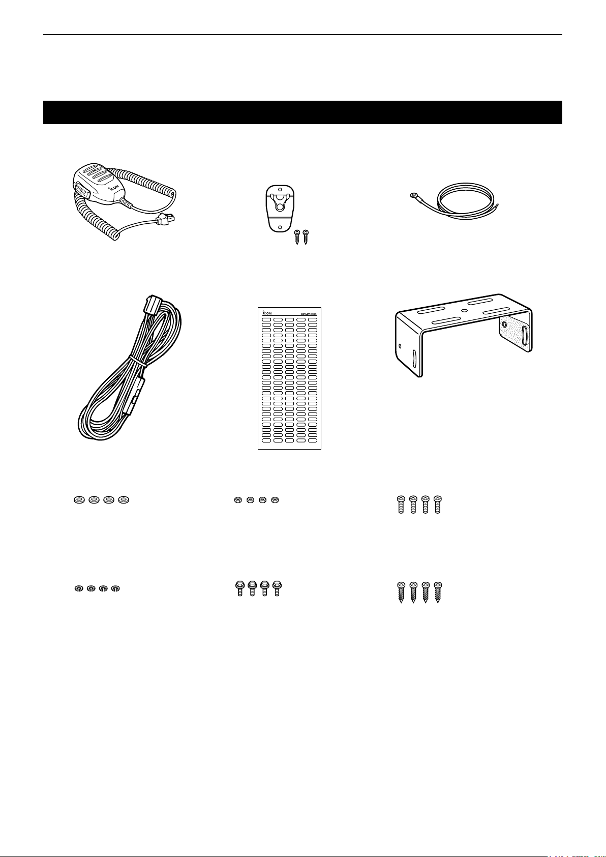
Supplied accessories
Microphone Microphone hanger
and screw set
DC power cable Function name
stickers*
Microphone
hanger cable
Mounting bracket
Flat washers Nuts Mounting screws
Spring washers Bracket bolts Self-tapping screws
* Used for labelling the programmable function keys according to their assigned functions.
1-2
1
ACCESSORIES AND INSTALLATION
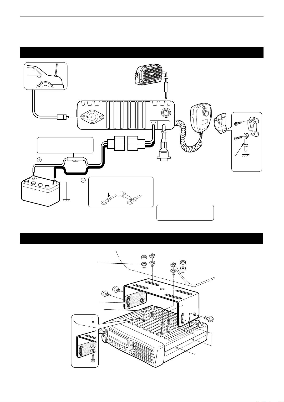
Rear panel connection
Antenna
WARNING! NEVER remove
R
the fuse holder from the DC
power cable.
Red
12 V
Battery
q ANTENNA CONNECTOR
Connects an antenna cable.
w EXTERNAL SPEAKER JACK
Connecta4–8Ωexternalspeaker.
q
t
Black
NOTE: Use the terminals as shown
below for the cable connections.
Crimp
Solder
Optional speaker
w
r OPTIONAL CABLE (OPC-1939)
Connectanexternalhorn,andsoon.
Ask your dealer for details.
t DC POWER RECEPTACLE
Connects to a 12 V DC power source.
Pay attention to polarities.
r
e MICROPHONE HANGER
Connect the supplied microphone
hanger to the vehicle’s ground to
use the microphone ON/OFF hook
functions.
e
Microphone
hanger cable
Mounting the transceiver
Flat washer
Felt*
Spring washer
WARNING! NEVER
R
to a 24 V battery. This could
damage the transceiver.
connect
When using
self-tapping screws
*Felt reduces vibration
1-3

Section 2
BASIC OPERATION
Power ON password..............................................................2-2
Keylock ................................................................................... 2-2
Channel selection .................................................................. 2-2
Zone selection .......................................................................2-2
Priority channel .....................................................................2-3
D Setting the Priority channel ..............................................................2-3
D Selecting the Priority channel ..........................................................2-3
D Cancelling the Priority channel ........................................................2-3
Monitor ...................................................................................2-3
Squelch...................................................................................2-3
2-1
2
BASIC OPERATION
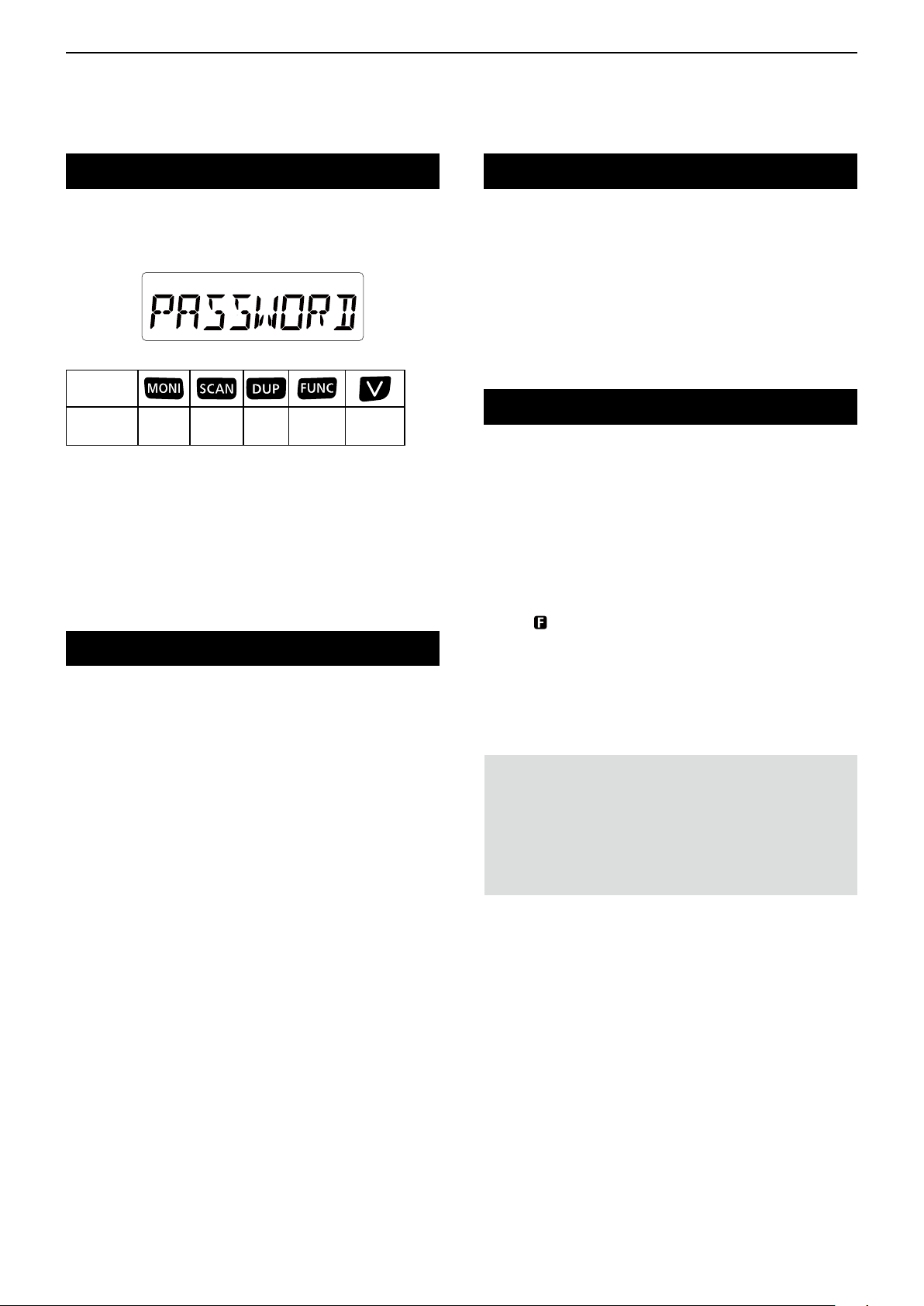
Power ON password
If the transceiver is set with a power ON password,
enter the password when turning ON the transceiver.
To enter the password, see the illustration below.
KEY
NUMBER
0
5
1
6
2
7
3
8
4
9
The password is a 4 digit code (example: 1234).
➥ Push the corresponding keys to enter your
password.
• Note that each key represents two digits. That means,
“3764” and “8769” are entered in exactly the same way
(requires no multiple or extended pushing.)
• The entered password will not be displayed.
• If “PASSWORD” does not disappear after entering, the
entered password is incorrect. Turn OFF the transceiver,
and then try again.
Keylock
Hold down for 2 seconds to electronically lock all
keys except [DUP], [FUNC], and [MONI] to prevent
accidental channel changing and function access.
Channel selection
There are 80 channels on the UHF CB and you have
access to the designated repeater channels.
You can select between them to communicate with the
intended person(s). The IC-410PRO is also capable
of storing a combination of up to 32 receive only and
private channels, using the optional CS-410PRO
cloning software.
Push [UP]/[DOWN] to select the channels.
Zone selection
(Selectable only when more than 1 zones are set,
using the optional CS-410PRO
A zone is a group of private channels, mainly used for
commercial applications. It allows only certain groups
or business departments to communicate within the
allocated zone.
1) Turn ON the Function mode.
➥ Push [FUNC].
• “ ” is displayed.
2) Enter the Zone Selection mode.
➥ Hold down [FUNC] for 2 seconds.
3) Select the desired zone.
➥ Push [UP]/[DOWN].
4) Return to the Standby mode.
➥ Push [FUNC].
cloning software)
To lock the keys:
➥ Hold down [DUP] for 2 seconds.
To unlock the keys:
➥ Hold down [DUP] for 2 seconds again.
D Non-locked keys
Even when the Keylock function is ON, you can use
the following keys for certain conditions.
[PTT]: You can hold down to
transmit, and release to
receive.
[DUP] (Normal mode): You can hold down for 2
seconds to unlock the keys.
[FUNC] (Normal mode): You can push to change
between Normal mode and
Function mode.
[MONI] (Normal mode): You can push to turn the
Monitor (open squelch)
function ON or OFF.
NOTE:
• The transceiver remains in the selected mode when
turned OFF and then ON again.
• CB-05, CB-R05 and CB-35 channels are for emergency
use, and are required to be left open for only
emergency use. CB-22 and CB-23 are used for only
receiving.
2-2

2
BASIC OPERATION
Priority channel
The Priority channel enables you to have quick access
to a specic channel. Only one channel can be set as
the Priority channel. “P” is displayed when the Priority
channel is set.
D Setting the Priority channel
1) Select a desired channel.
➥ Push [UP]/[DOWN].
2) Turn ON the Function mode.
➥ Push [FUNC].
• “ ” is displayed.
3) Set the selected channel as the Priority channel.
➥ Hold down [DUP] for 2 seconds.
• “P” is displayed.
D Selecting the Priority channel
1) Turn ON the Function mode.
➥ Push [FUNC].
• “ ” is displayed.
2) Select the Priority channel.
➥ Push [DUP].
• “N/A” is displayed when no Priority channel is set.
D Cancelling the Priority channel
1) Turn ON the Function mode.
➥ Push [FUNC].
• “ ” is displayed.
2) Select the Priority channel.
➥ Push [DUP].
3) Turn ON the Function mode.
➥ Push [FUNC].
• “ ” is displayed.
4) Cancelling the Priority channel.
➥ Hold down [DUP] for 2 seconds.
• “P” disappears.
Monitor
The Monitor function opens the any squelch, enabling
you to receive weak signals. This allows quick access
to the open squelch setting.
Push [MONI] to turn the Monitor function ON or OFF.
Squelch
In order to quietly receive signals, set the squelch
level to suit your environment. This eliminates
background noise when there are no signals present.
A higher level is better for inner cities or noisy areas,
and a lower level is more benecial in quiet, rural and
country areas.
Setting the squelch level:
1) Enter the Set mode.
➥ Hold down [FUNC] for 2 seconds.
2) Select the “SQL” menu.
➥ Push [FUNC] until the “SQL” menu is displayed.
3) Set the squelch level to between 0 and 9.
➥ Push [UP]/[DOWN].
4) Exit the Set mode.
➥ Hold down [FUNC] for 2 seconds.
2-3

Section 3
SET MODE
Set mode items ...................................................................... 3-2
D Set mode sequence .........................................................................3-2
D Squelch Level “SQL” ........................................................................3-3
D Scan mode “SCAN-M” .....................................................................3-3
D CTCSS/DTCS ..................................................................................3-3
D Backlight “LIGT” ...............................................................................3-3
D Beep “BEEP”....................................................................................3-3
D Beep Level “BEPV” ..........................................................................3-3
D RF Power “RFPOW” ........................................................................3-3
D Quiet mode “QUIET” ........................................................................3-4
D Lockout “LOCK-O” ...........................................................................3-4
D Roger beep “RGR-B” .......................................................................3-4
D Battery Voltage “BATT” ....................................................................3-4
D Auto Power OFF “AP-OFF”..............................................................3-4
D Signal Monitor “SMON” ....................................................................3-4
D Horn “HORN” ...................................................................................3-4
D RX VFO “RX VFO” ...........................................................................3-4
D Scan Stop Timer “S-TIME” ...............................................................3-4
D Scan Restart “SCAN-R” ...................................................................3-4
D Mic Gain “MIC” .................................................................................3-5
D Lone Worker “LONE” .......................................................................3-5
D AF Minimum Level “AFMIN” .............................................................3-5
D Own ID .............................................................................................3-5
3-1
3
SET MODE
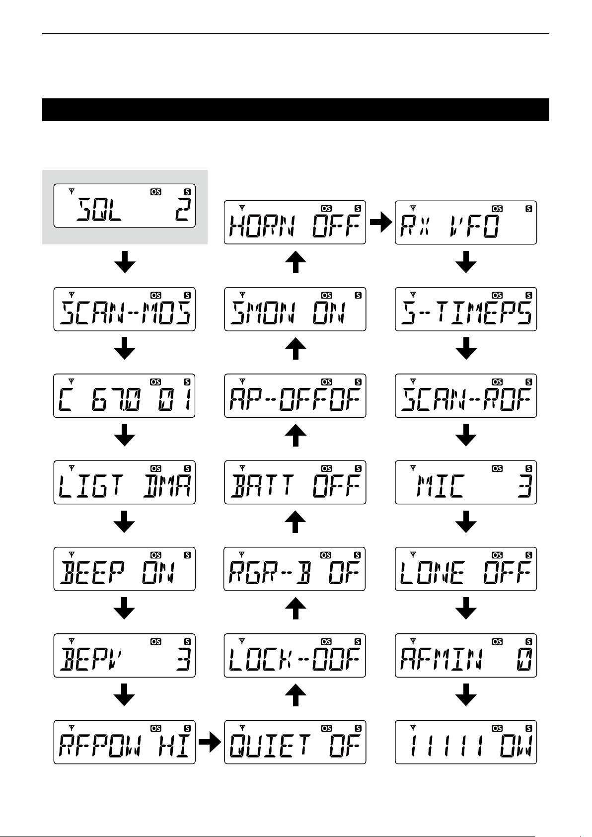
Set mode items
D Set mode sequence
The table below describes the sequence of the items in the Set mode.
• The sequence is as shown below when you push [FUNC] in the Set mode.
• Squelch level
• Horn • RX VFO
Starting item
• Scan mode
• CTCSS/DTCS*
• Backlight
• Beep
• Signal Monitor
1
• Auto Power Off
• Battery Voltage
• Roger Beep
• Scan Stop Timer
• Scan Restart
• Mic Gain
• Lone Worker*
2
• Beep Level
• Lockout
• RF Power • Quiet mode
*1 Selected CTCSS or DTCS code is displayed.
2
*
May not be displayed, depending on the transceiver’s setting.
3
*
5 digit Own ID is displayed.
3-2
• AF Minimum Level*
• Own ID*2 *
3
2
 Loading...