

Page 1

i40S
UHF C.R.S.TRANSCEIVER
INSTRUCTION MANUAL
Page 2

i
FOREWORD
READ ALL INSTRUCTIONS carefully and completely
before using the transceiver.
SA VE THIS INSTRUCTION MANUAL — This in-
struction manual contains important operating instructions for
the IC-40S.
EXPLICIT DEFINITIONS
The explicit definitions below apply to this instruction manual.
This device complies with Standards Australia Specification no.AS/NZS4365-1995
& AS4295-1995.
CAUTIONS
R WARNING! NEVER hold the transceiver so that the
antenna is very close to, or touching exposed par ts of the
body, especially the face or eyes, while transmitting. The
transceiver will perform best if the microphone is 5 to 10 cm
away from the lips and the transceiver is vertical.
R WARNING! NEVER operate the transceiver with a
headset or other audio accessories at high volume levels.
Hearing experts advise against continuous high volume operation. If you experience a ringing in your ears, reduce the
volume level or discontinue use.
NEVER connect the transceiver to an AC outlet or to a
power source of more than 16 V DC. Such a connection will
damage the transceiver.
NEVER connect the transceiver to a power source that is
DC fused at more than 5 A. Accidental re verse connection will
be protected by this fuse, higher fuse values will not give any
protection against such accidents and the transceiver will be
ruined.
NEVER attempt to charge alkaline or dry cell batteries. Be-
ware that external DC power connections will charge batteries
inside the battery case.This will damage not only the battery
case but also the transceiver.
WORD
R
WARNING
CAUTION
NOTE
DEFINITION
Personal injury, fire hazard or electric
shock may occur.
If disregarded, inconvenience only. No risk
of personal injury, fire or electric shock.
Equipment damage may occur.
n33
Page 3
ii
DO NOT push the PTT when not actually desiring to trans-
mit.
DO NOT allow children to play with any radio equipment
containing a transmitter.
DO NOT operate the transceiver near unshielded electrical
blasting caps or in an explosive atmosphere.
AVOID using or placing the transceiver in direct sunlight or
in areas with temperatures below –10°C or above +60°C.
The use of non-Icom battery packs/chargers may impair
transceiver performance and invalidate the warranty.
Even when the transceiver power is OFF, a slight current still
flows in the circuits. Remove the battery pack or case from
the transceiver when not using it for a long time. Otherwise,
the battery pack or installed dry cell batteries will become exhausted.
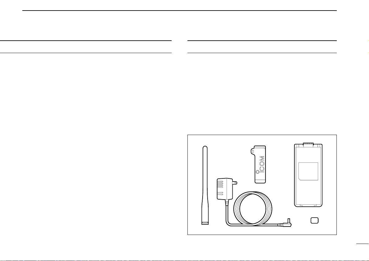
SUPPLIED ACCESSORIES
Accessories included with the transceiver: Qty.
q Antenna .......................................................................... 1
w Belt clip ........................................................................... 1
e Battery pack attached to the transceiver* ....................... 1
r Wall charger* .................................................................. 1
t 1922A REAR-SHEET (for dealer use) ........................... 1
* The battery pack (BP-195 or BP-196) may differ depending on
version. Some versions do not include a battery pack and wall
charger.
+_
qw e
r
t
Page 4

FOREWORD ........................................................................ i
EXPLICIT DEFINITIONS ..................................................... i
CAUTIONS ........................................................................... i
SUPPLIED ACCESSORIES................................................. ii
TABLE OF CONTENTS ...................................................... iii
1 ACCESSORY ATTACHMENT ....................................... 1
2 PANEL DESCRIPTION ............................................ 2–4
■Panel description ........................................................ 2
■Function display .......................................................... 4
3 BASIC OPERATION ................................................ 5 –7
■Receiving and transmitting ......................................... 5
■Display backlighting .................................................... 6
■Lock function .............................................................. 6
■Monitor function .......................................................... 6
■Repeater operation ..................................................... 7
4 SCAN OPERATION ................................................ 8–10
■Scan types .................................................................. 8
■Open scan .................................................................. 8
■Group and priority scans ............................................ 9
■Setting scan tag .......................................................... 9
■Scan resume condition ............................................. 10
5 TONE SQUELCH OPERATION .................................. 11
■Tone squelch operation ............................................ 11
■Pocket beep operation .............................................. 11
6 BATTERY PACKS ................................................ 12– 14
■Charging precautions ............................................... 12
■Battery pack charging ............................................... 12
■About the battery pack .............................................. 14
■Installing batteries in the battery case ...................... 14
7 OTHER FUNCTIONS ........................................... 15–16
■Time-out timer .......................................................... 15
■Power saver .............................................................. 15
■Confirmation beeps .................................................. 15
■Transmit lockout ........................................................ 16
■Optional HM-75A functions ....................................... 16
8 TROUBLESHOOTING ................................................ 17
9 SPECIFICATIONS ....................................................... 18
10 OPTIONS ..................................................................... 19
iii
TABLE OF CONTENTS
Page 5
1
1
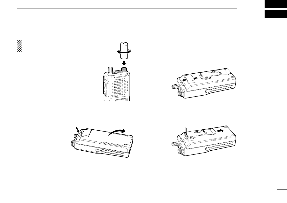
ACCESSORY ATTACHMENT
DAntenna
CAUTION:
Transmitting without an
antenna may damage the transceiver.
Insert the supplied antenna into the antenna connector and screw down the antenna as shown at right.
Keep the jack cov er attached when jac ks
are not in use to avoid bad contacts from
dust and moisture.
DBattery pack replacement
To remove:
Push and hold the battery release downwards,
then pull the battery
pack upwards as shown
at right.
To attach:
Mate the notched ends of the battery pack and the transceiver, and push the battery pack until it clicks into place.
DBelt clip
Conveniently attaches to your belt.
To attach:
Slide the belt clip into the plastic loop on the back of the battery case/pack.
To remove:
Push the top of the belt clip towards the transceiver and at
the same time, push it downward and free of the plastic loop.
Page 6
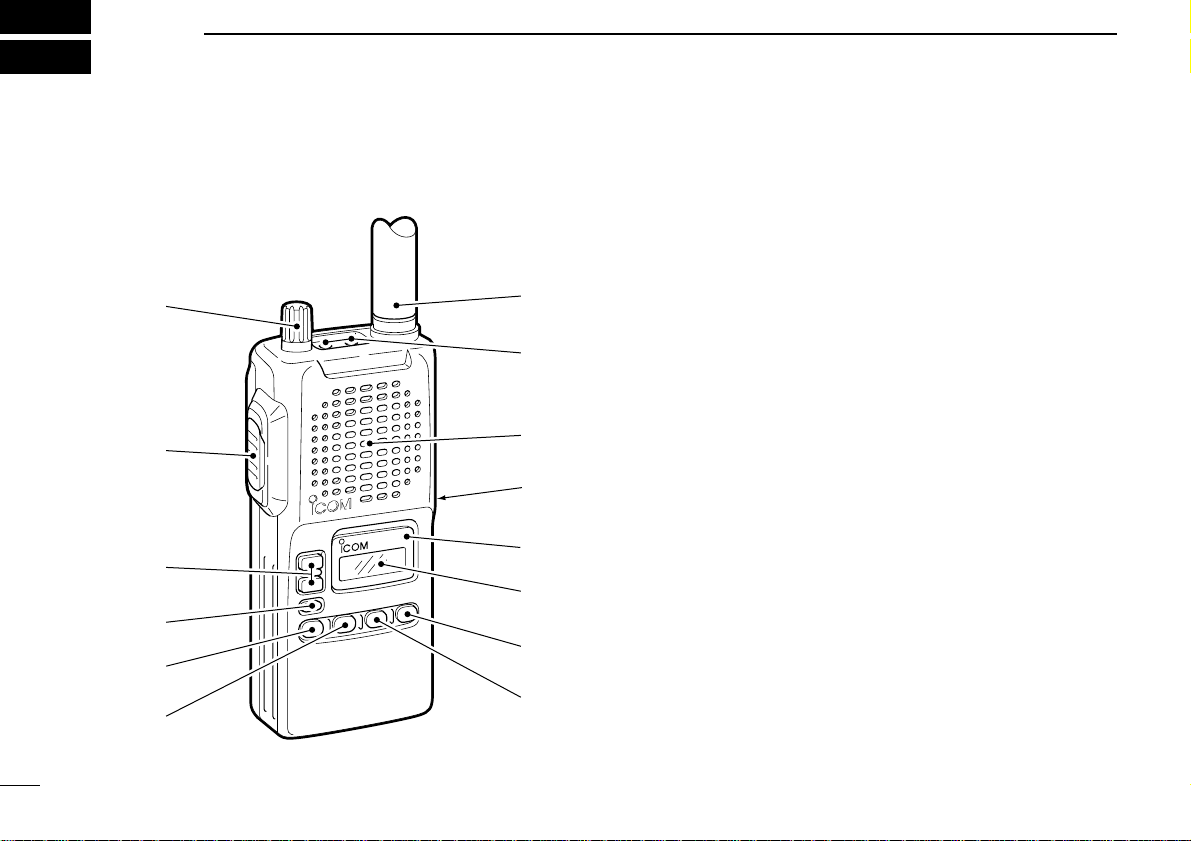
■ Panel description
q VOLUME CONTROLS [VOL] (p.5)
Turns power ON and adjusts the audio level.
w PTT SWITCH [PTT] (p.5)
Push and hold to transmit; release to receive.
e CHANNEL UP/DOWN SWITCHES [Y]/[Z]
➥Push to select the operating channel.(p. 5)
➥Select item conditions in set mode.
r MONITOR SWITCH [–]
➥Push to toggle the monitor function ON or OFF. (p.6)
➥Activates the following functions in order when pushed
for 2 sec.(p. 11)
•Subaudible tone encoder—“T”appears.
•Tone squelch—“TSQL” appears.
•Pocket beep—“TSQLë” appears.
•No tone operation—no indicator appears.
t SCAN SWITCH [SCN]
➥Starts and stops the selected scan when pushed. (p.8)
➥Toggles the displayed channel to be scanned or by-
passed by the selected scan when pushed for 2 sec.(p.
9)
•“X” appears for a scan (tag) channel.
2
2
PANEL DESCRIPTION
q
w
e
r
t
y
!4
!3
!2
!1
!0
o
i
u
Page 7

3
2
PANEL DESCRIPTION
y SCAN TYPE SELECTION SWITCH [O/G]
➥Push to select the scan types in order.(p.8)
•Open scan—“OS” appears.
•Group scan—“GS” appears.
•Priority scan—“PS” appears.
➥When the group or priority scan is selected, this switch
sets the displayed channel as the priority channel for the
selected scan when pushed for 2 sec.(p. 9)
•While the priority channel is set, the priority channel is displayed at the right of the operating channel.
u OUTPUT POWER SWITCH [LOW]
➥Push this switch to toggle between high and low output
power. (p.5)
➥Enters set mode when pushed for 2 sec.
➥Scrolls the set mode contents while in the set mode.
i DUPLEX SWITCH [DUP]
➥Toggles the selected channel between duplex or simplex
operation on channels 1 to 8.(p. 7)
➥Toggles the lock function ON and OFF when pushed for
2 sec. (p. 6)
•“ ” appears when the lock function is activated.
o FUNCTION DISPLAY (p.4)
!0 TRANSMIT INDICATOR (p.5)
Lights red while transmitting.
!1 EXTERNAL DC POWER JACK [CHARGE]
Connect a 12 to 16 V DC power source using the optional
cables, CP-12L or OPC-254L, to charge the attached battery pack; or connect the BC-110V wall charger for charging.
CAUTION:This connection is for charging ONLY.
Power to the transceiver must be turned OFF during
charging.
!2 SPEAKER/MICROPHONE
!3 EXTERNAL SPEAKER AND MICROPHONE JACKS
[SP/MIC]
Connect an optional speaker-microphone or headset, if desired. The internal microphone and speaker will not function when either is connected. (See p. 19 for a list of
available options.)
!4 ANTENNA CONNECTOR (p. 1)
Connects the supplied antenna.
Page 8
4
2
PANEL DESCRIPTION
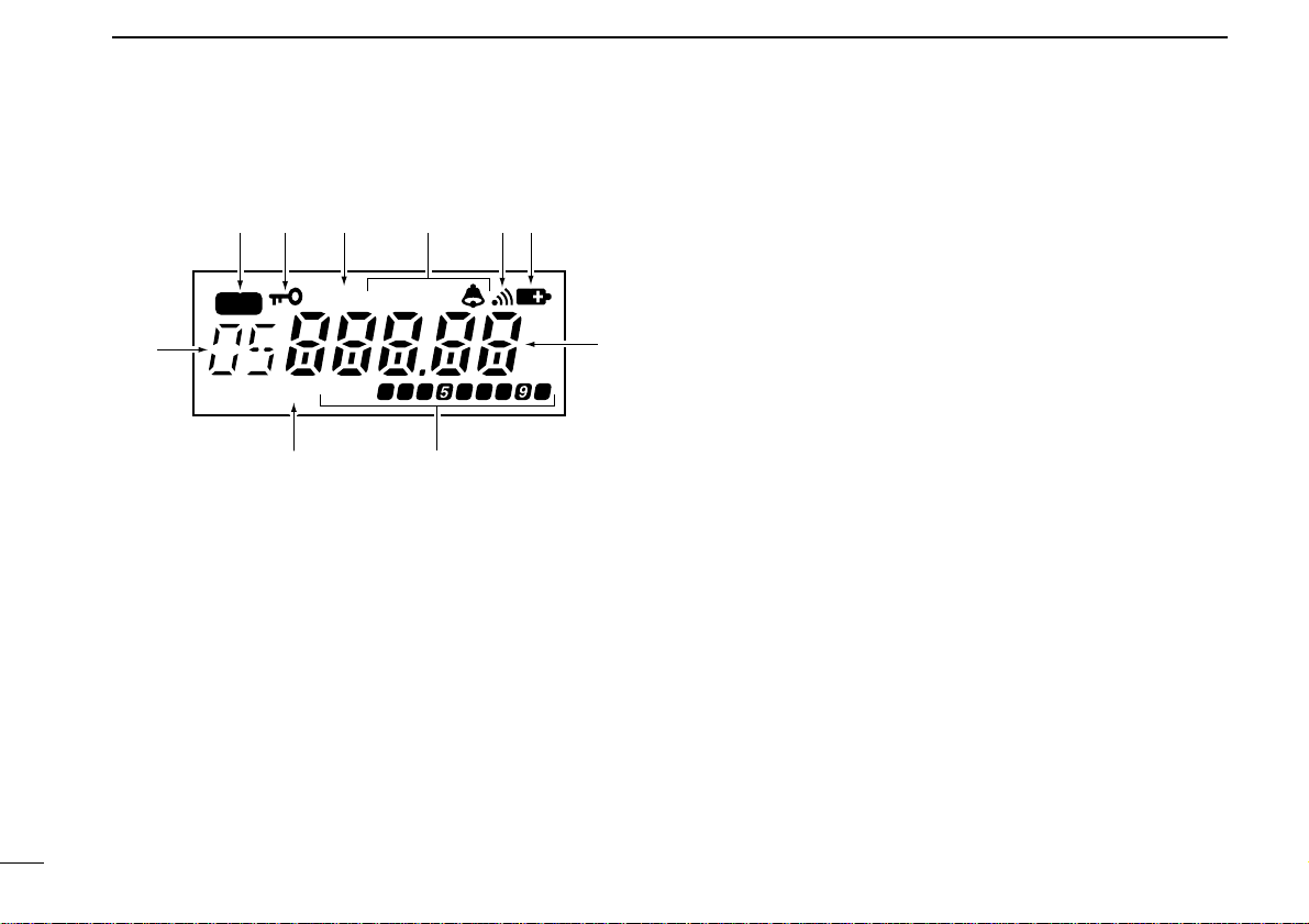
■ Function display
q TAG CHANNEL INDICATOR (p.9)
Appears when the selected channel is set as a tag channel.
•Tag channels can be set separately for each scan type.
w LOCK INDICATOR (p.6)
Indicates that the lock function is in use.
e DUPLEX INDICATOR (p.7)
Appears when semi-duplex operation (repeater operation)
is in use.
•“DUP” appears when duplex is selected.
•This function is available for channels 1 to 8 only.
r TONE INDICATORS (p. 11)
“T” appears when the subaudible tone encoder is in use;
“T SQL” appears when the tone squelch function is acti-
vated and “TSQLë” appears during pocket beep operation.
t MONITOR INDICATOR (p. 6)
Appears when the monitor function is turned ON (the
squelch opens).
y LOW BATTERY INDICATOR
➥Appears when the battery is nearing exhaustion.
➥Appears and flashes when battery replacement is nec-
essary.
u CHANNEL READOUT
Shows the operating channel, priority channel, set mode
contents, etc.
i BUSY AND SIGNAL INDICATORS
➥“BUSY” appears when receiving a signal or when the
squelch is open.
➥The signal indicators show the relative signal strength
while receiving.
o LOW POWER INDICATOR (p.5)
Appears when low output power is selected.
!0 SCAN TYPE INDICA T OR (p. 8)
Shows the selected scan type: open scan (OS), group
scan (GS) or priority scan (PS).
MR
DUP
BUSY
T SQL
LOW
qw e r yt
u
oi
!0
Page 9

5
3
BASIC OPERATION
■ Receiving and transmitting
CAUTION:Transmitting without an antenna may dam-
age the transceiver.
q Rotate [VOL] clockwise to turn power ON, then set to the
10 o’clock position.
•If “T SQL” appears on the display, push [–] for 2 sec. once or
twice to cancel the tone squelch or pocket beep.(p.11)
w Select the desired channel with the [Y]/[Z] switches.
•When receiving a signal, “BUSY” appears and audio is emitted
from the speaker.
•Further adjustment of [VOL] may be necessary at this point.
•Push [–] to toggle the monitor function ON and OFF. (p.6)
e Push [LOW] to select the output power if necessary.
•“LOW” appears when low power is selected.
•Choose low power to conserve battery power , choose high po wer
for longer distance communications.
r Push and hold [PTT] to transmit, then speak into the mi-
crophone.
•Transmit indicator lights.
t Release [PTT] to receive.
IMPORTANT:To maximiz e the readability of y our transmitted signal, pause a few sec.after pushing [PTT], hold the
microphone 10 to 15 cm from your mouth and speak at a
normal voice level.
NOTE: The transceiver has a power save function to conserve battery power.The power sav e function activates automatically when no signal is received for 5 sec.
q Set volume
w Monitor switch
r Speak into
microphone
e Set output
power
r Push to transmit
t Release to
receive
w Select channel
Page 10

6
3
BASIC OPERATION
■ Display backlighting
The transceiver has display backlighting with a 5 or 10 sec.
timer for nighttime operation. The display bac klighting can be
turned ON continuously or turned OFF, if desired.
➥Push any switch except [PTT] to turn the backlighting ON.
•When the 5 or 10 sec.timer is set, the backlighting will automatically turn OFF when switches have not been operated for 5 or 10
sec., respectively.
DSetting the backlighting timer
q Push [LOW] for 2 sec. to enter set mode.
w Push [LOW] several times until “LI” appears.
e Push [Y] or [Z] to select the backlighting timer.
r Push [LOW] for 2 sec. to exit set mode.
■ Lock function
The lock function prevents accidental channel changes and
accidental function access. [PTT] and the backlight function
can be used while the lock function is in use.
➥Push [DUP] for 2 sec. to toggle the lock function ON and
OFF.
■ Monitor function
This function is used to listen to weak signals or to open the
tone squelch manually.
Push [–] to toggle the monitor function ON or OFF.
MR
“ ” appears when the
lock function is in use.
MR
BUSY
“ ” appears when the
monitor function is in use.
5 sec. timer
10 sec. timer
Continuously ON
Continuously OFF
[
Page 11

7
3
BASIC OPERATION
■ Repeater operation
A repeater amplifies received signals and retransmits them
on a different channel, allowing you to communicate over
greater distances with improved reliability. When using a repeater, the transmit channel is shifted from the receive channel by 30 channels.
q Select the receive channel from 1 to 8 (repeater output
channel).
w Push [DUP] to set duplex.
•“DUP” appears.
•The duplex setting aff ects the selected channel only and is auto-
matically programmed into the selected channel.
e Push and hold [PTT] to transmit.
•The displayed channel automatically changes to the transmit
channel (repeater input channel).
•If “T SQL” appears on the display, push [–] for 2 sec. twice to can-
cel the tone squelch function.
r Release [PTT] to receive.
t To cancel the duplex setting, push [DUP] on the desired
channel.
DSetting CTCSS tones for
repeater and tone squelch
operation
Repeaters may require CTCSS (subaudible) tones to be accessed. CTCSS tones are superimposed over your normal
signal and must be set in advance.
This setting is commonly used for the tone squelch operation.
q Select the desired memory channel to be programmed.
w Push [LOW] for 2 sec. to enter set mode.
e Push [LOW] several times until “Ct” appears.
r Push [Y] or [Z] to select the CTCSS tone frequency.
t Push [LOW] for 2 sec. to exit set mode.
67.0
69.3
71.0
71.9
74.4
77.0
79.7
82.5
85.4
88.5
91.5
94.8
97.4
100.0
103.5
107.2
110.9
114.8
118.8
123.0
127.3
131.8
136.5
141.3
146.2
151.4
156.7
159.8
162.2
165.5
167.9
171.3
173.8
177.3
179.9
183.5
206.5
210.7
218.1
225.7
229.1
233.6
186.2
189.9
192.8
196.6
199.5
203.5
241.8
250.3
254.1
(Unit: Hz)
[
Page 12

8
4
SCAN OPERATION
■ Scan types
The transceiver has 3 scan types with tag functions and 4 resume conditions providing scanning versatility.
Tag channels are independently set for open, group and priority scans. Initially, all channels may be set as tag channels
for all scans.
■ Open scan
Open scan searches for transmitted signals automatically and
makes it easier to locate new stations for contact or listening
purposes.
During open scan, transmission is not possible except on a
busy channel.
q Push [O/G] to select open scan.
- “OS”appears when the open scan is selected.
w Push [SCN] to start open scan.
- Cancelling tag channels speeds up the scan interval. (p. 9)
e When receiving a signal, scan pauses and resumes ac-
cording to the selected scan resume condition. (p. 10)
r Push [SCN] to stop the scan.
Repeatedly scans all tag channels in sequence.
ch 40
ch 1 ch 2 ch 3
ch 4
ch 5
ch 6ch 39
Repeatedly watches a priority channel while scanning
only specified channels (tag channels).
ch 8
ch 26ch 12
Priority
channel
OPEN SCAN
XX
X
X
X
X
GROUP OR PRIORITY
SCAN
X
XX
MR
Start channel
Scanning channel is displayed.
Page 13

9
4
SCAN OPERATION
■ Group and priority scans
Group and priority scans repeatedly watch a priority channel
while scanning only specified channels. This is useful when
waiting for calls on the priority channel or several specified
channels.
Group and priority scans behave differently when transmitting. During group scan, transmission is possible on a busy
channel only. During priority scan, transmission is possible on
a priority channel (or start channel) only.
q Push [O/G] to select open scan.
- “GS” or “PS” appears when the
group or priority scan is selected, respectively.
w Select the priority channel if
desired.
- Push [Y] or [Z] key to select a
channel.
- Push [O/G] for 2 sec. to set the
channel to the priority channel.
e Push [SCN] to start group or priority scan.
- Cancelling tag channels speeds up the scan interval.
r When receiving a signal, scan pauses and resumes ac-
cording to the selected scan resume condition. (p. 10)
t Push [SCN] to stop the scan.
■ Setting scan tag
Scan tag must be set before starting scan. Tag channels are
independently set for open, group and priority scan.
q Select the desired channel.
w Push [O/G] to select the desired scan type.
e Push [SCN] for 2 sec.to set the channel as a tag channel.
- “X”appears for tag channels.
r Repeat step e to cancel the tag channel setting.
For open scan, cancel the tag channel setting to skip undesired channels such as usually busy channels. This
speeds up the scan interval. All memory channels may be
set as tag channels by default.
For group scan, set only often-used channels as tag channels. All memory channels may be set as tag channels by
default.
MR
Start channel
Priority indication
Scanning channel
MR
SCN
for 2 sec.
Appears for channels
to be scanned.
Page 14

10
4
SCAN OPERATION
■ Scan resume
condition
The scan resume condition can be selected as a pause or
timer scan.
q Push [LOW] f or 2 sec.to enter
set mode.
w Push [LOW] several times
until “SC”appears.
e Push [Y] or [Z] to select the
scan resume timer.
- “t-05” :Scan pauses 5 sec.
while receiving a signal.
- “t-10” :Scan pauses 10 sec.
while receiving a signal.
- “t-15” :Scan pauses 15 sec.
while receiving a signal.
- “P-05” : Scan pauses until the
signal disappears and
then resumes 5 sec.
thereafter.
r Push [LOW] for 2 sec. to exit
set mode.
[
Pauses until the signal
disappears.
10 sec. timer for resume
condition.
15 sec. timer for resume
condition.
5 sec. timer for resume
condition.
Page 15

11
5
TONE SQUELCH OPERATION
■ Tone squelch operation
The tone squelch opens only when receiving a signal containing a matching CTCSS (subaudible) tone.Y ou can silently
wait for calls from group members using the same tone.
q Set the desired channel.
w Set the desired CTCSS tone in set mode.
•See p.7 for tone frequencies and programming information.
e Push [–] for 2 sec.several times until “TSQL”appears.
r When the received signal includes a matching tone,
squelch opens and the signal can be heard.
•When the received signal’s tone does not match, tone squelch
does not open, however, the S-indicator shows signal strength.
•To open the squelch manually, push [–].
t Operate the transceiver in the normal way.
y To cancel the tone squelch, push [–] for 2 sec.twice.
NOTE:The transceiver has 51 tone frequencies and consequently their spacing is narrow compared with units having 38 tones. Therefore, some tone frequencies may
receive interference from adjacent tone frequencies.
Tone frequencies and tone squelch ON/OFF settings are
automatically stored in memory channels for easy recall.
■ Pocket beep operation
This function uses CTCSS (subaudible) tones for calling and
can be used as a “common pager” to inform you that someone has called while you were away from the transceiver.
DWaiting for a call from a specific station
q Set the operating channel.
w Set the desired CTCSS tone in set mode.
•See p.7 for tone frequencies and programming information.
e Push [–] for 2 sec.several times until “ TSQLë” appears
in the function display.
r When a signal with the correct tone is received, the
transceiver emits beep tones and flashes “TSQLë.”
t Push [PTT] to answer or push [–] to stop the beeps and
flashing.
•Tone squelch is automatically selected.
DCalling a waiting station using pocket beep
A subaudible tone matched with the station’s tone frequency
is necessary.Use the tone squelch at left or a CTCSS (subaudible) tone encoder (p.7).
Page 16

■ Charging
precautions
NEVER attempt to charge dr y cell bat-
teries. This will cause internal liquid
leakage and damage the battery case
and transceiver.
NEVER connect two or more chargers
at the same time.
Charging may not occur under temperatures of 10°C (50°F) or over temperatures of 40°C (104°F).
When using BC-119: If the charge
indicator flashes orange, vehicle battery voltage is low and charging is
not possible. Check the vehicle battery voltage in this case.If the charge
indicator flashes red, there may be a
problem with the battery pack (or
charger). Re-insert the batter y pack
or contact your dealer.
■ Battery pack
charging
The BP-195 or BP-196
BATTERY PACK
includes rechargeable Ni-Cd batteries
and can be charged approx.300 times.
Charge the battery pack before first operating the transceiver or when the battery pack becomes exhausted.
If you want to be able to charge the battery pack more than 300 times, the following points should be observed:
1.Avoid o vercharging.The charging pe-
riod should be less than 48 hours.
2. Use the battery until it becomes al-
most completely exhausted under
normal conditions. We recommend
battery charging just after transmitting
becomes impossible.
D
Rapid charging with the BC-119
The optional BC-119 provides rapid
charging of battery packs.
One AD-81 and an AC adapter (may be
supplied with the BC-119 depending on
version) are additionally required.
•Charging periods: 1.5 hours (w/BP-195)
2 hours (w/BP-196)
12
6
BATTERY PACKS
Turn power
OFF.
BC-119+
AD-81
BC-119+
AD-81
Check orientation
for correct charging.
(Packed together
as the AD-81.)
Check orientation
for correct charging.
(Packed together
as the AD-81.)
Page 17

13
6
BATTERY PACKS
DMultiple charging with the BC-121
The optional BC-121 allows up to 6 battery packs to be
charged simultaneously.
Six AD-81’s and an AC adapter (may be supplied with the
BC-121 depending on version) are additionally required.
•Charging periods: 1.5 hours (w/BP-195)
2 hours (w/BP-196)
DRegular charging
q Attach the battery pack to the transceiver.
w Be sure to turn the transceiver power OFF.
e Connect the AC adapter (BC-110V) or optional cable
(CP-12L or OPC-254L) as shown below.
•Charging periods: 10 hours (w/BP-195)
15 hours (w/BP-196)
IC-40S with
attached
battery case
(pack)
BC-110V
CP-12L
(optional)
OPC-254L
(optional)
To a 12 to
16 V DC
power source
To
[CHARGE]
white
black
M
U
L
T
I
-
C
H
A
R
G
E
R
AC adapter
(not supplied with some versions)
Charge indicator
(each indicator functions
independently)
Page 18

14
6
BATTERY PACKS
■ About the battery pack
DOperating period
Depending on the attached battery pack, the operating period
of the transceiver varies. Refer to the last page for battery
pack specifications.
DBattery pack life
If your battery pack seems to have no capacity even after
being fully charged, completely discharge it by leaving the
power ON overnight. Then, fully charge the battery pack
again.
If the battery pack still does not retain a charge (or very little),
a new battery pack must be purchased.
■ Installing batteries in the
battery case
When using a battery case, install 8 AA (R6) size Ni-Cd or alkaline batteries as illustrated below.
q Remove the bat-
tery case from the
transceiver.
w Install 8 × AA (R6)
size Ni-Cd or alkaline batteries.
•Be sure to observe
the correct polarity.
● NEVER connect DC power to the transceiver when in-
stalling dry cell or alkaline batteries. Such a connection will
damage the transceiver.
● Be careful of battery overcharging.When operating via external DC power, installed batteries are simultaneously
charged.
● Keep battery contacts clean. It’s a good idea to clean bat-
tery terminals once a week.
Page 19

OTHER FUNCTIONS
15
7
■ Time-out timer
To prevent continuous, extend transmissions, the transceiver
has a time-out timer. This timer turns a transmission OFF 1,
2, 3 or 4 min. after it starts. This timer can be cancelled.
Approx. 5 sec. before the time-out time elapses, the transceiver emits a beep tone.
q Push [LOW] for 2 sec. to enter set mode.
w Push [LOW] several times until “tt” appears.
e Push [Y] or [Z] to select the time-out time or to turn the
function OFF.
- 1, 2, 3 and 4 minutes and OFF are available.
r Push [LOW] for 2 sec. to exit set mode.
■ Power saver
The power saver function reduces the current drain to conserve battery power.
q Push [LOW] for 2 sec. to enter set mode.
w Push [LOW] several times until “PS” appears.
e Push [Y] or [Z] to turn the power saver ON or OFF, re-
spectively.
r Push [LOW] for 2 sec. to exit set mode.
■
Confirmation beeps
You can select silent operation by turning beep tones OFF or
you can have confirmation beeps sound at the push of a
switch by turning beep tones ON.The beep tone volume is
linked with [VOL].
q Push [LOW] for 2 sec. to enter set mode.
w Push [LOW] several times until “bE” appears.
e Push [Y] or [Z] to turn the confirmation beep ON or OFF,
respectively.
r Push [LOW] for 2 sec. to exit set mode.
[
[
[
4 min. time-out timer is selected.
Time-out timer is cancelled.
Page 20

16
7
OTHER FUNCTIONS
■ Transmit lockout
The transmit lockout function inhibits transmission while receiving a signal or when receiving a signal with an unmatched
CTCSS tone.
q Push [LOW] for 2 sec. to enter set mode.
w Push [LOW] several times until “Lo” appears.
e Push [Y] or [Z] to select the transmit lockout function or
to turn the function OFF.
- “RPt” :
Transmission is impossible
when receiving a signal with
an unmatched CTCSS tone.
- “bUSy”:
Transmission is impossible
when receiving a signal.
- “oFF” :
Transmission is always possible.
r Push [LOW] for 2 sec. to
exit set mode.
■ Optional HM-75A functions
CAUTION: When connecting the HM-75A to the trans-
ceiver, make sure that power to the transceiver is turned
OFF, otherwise the CPU may malfunction.
DTurning the microphone remote control
function ON/OFF
q Push [LOW] for 2 sec. to enter set mode.
w Push [LOW] several times until “mC” appears.
e Push [Y] or [Z] to turn the microphone remote control
function ON or OFF, respectively.
r Push [LOW] for 2 sec. to exit set mode.
DHM-75A functions
The optional HM-75A allows you to remotely select operating
channels, output power, etc.
A SWITCH
Toggles monitor function ON
and OFF.
B SWITCH
Selects the output power.
Y/Z SWITCHES
Selects the operating channels.
Transmission is impossible
when receiving a signal with
an unmatched CTCSS tone.
Lockout function is cancelled.
Transmission is impossible
when receiving a signal.
A
B
OFF ON
LOCK
Lock switch:
Locks all
switches
except [PTT].
Earphone
jack
PTT
switch
Page 21

17
8
TROUBLESHOOTING
If your transceiver seems to be malfunctioning, please check
the following points before sending it to a service center.
PROBLEM POSSIBLE CAUSE SOLUTION REF.
No power comes ON. •The battery is exhausted.
•Bad connection to the battery pack.
No sound comes from
the speaker.
Transmitting is impossible.
No contact possible with
another station.
The displayed channel
cannot be changed.
Scan does not start. •The monitor function is activated.
No beep sounds. •Beep tones are turned OFF. •Turn beep tones ON in SET mode. p. 15
•Volume level is too low.
•Tone squelch is activated.
•The battery is exhausted. •Recharge the battery pack. p. 12
•The transceiver is set to semi-duplex.
•The other station is using tone squelch.
•Lock function is activated. •Push [DUP] for 1 sec. to cancel the func-
•Scan tag is not programmed.
•Recharge the battery pack.
•Check the connection to the transceiver.
•Set [VOL] to a suitable level.
•Turn the tone squelch OFF.
•Push [DUP] to set to simplex.
•Turn ON the tone squelch function.
tion.
•Push [–] to cancel the function.
•Set scan tag to desired channels.
p. 12
—
p. 5
p. 11
p. 7
p. 11
p. 7
p. 6
p. 9
Page 22

18
9
SPECIFICATIONS
DGeneral
•Frequency coverage : 450.000–480.000 MHz
(Incl. all 40 UHF C.R.S. ch.)
• Mode : FM (16K0F3E)
•Tuning step increment :25 kHz
•Acceptable power supply : 9.6 V DC nominal
(negative ground) (authorized battery packs)
•Usable temp.range : –10˚C to +60˚C
•Frequency stability : ±5 ppm
•Current drain (approx.) :
Tx at 5 W 1.6 A
at 1 W 0.7 A
Rx standby 60 mA
max. audio 250 mA
power saved 13 mA
•Antenna impedance : 50 Ω (nominal)
•Dimensions : 57(W)✕140(H)✕37(D) mm
(projections not incl.)
•Weight (with BP-195) : 370 g
DTransmitter
•Output power : Max.5 W (at 9.6 V DC)
•Modulation :Variable reactance frequency
modulation
•Max.frequency deviation :±5 kHz
•Spurious emissions : 70 dB typical
•Adjacent channel power : 70 dB typical
•External mic. connector : 3-conductor 2.5 (d) mm/2 kΩ
DReceiver
•Receive system : Double conversion
superheterodyne
•Intermediate frequencies :1st 46.35 MHz
2nd 450 kHz
•Sensitivity :0.25 µV at 12 dB SINAD
•Squelch sensitivity :0.25 µV typical (at threshold)
•Adjacent ch.selectivity : 70 dB typical
•Spurious response : 70 dB typical
•Intermodulation rejection : 65 dB typical
•Audio output power : 500 mW typical at 10%
(at 9.6 V DC) distortion with an 8 Ω load
•External SP connector : 2-conductor 3.5 (d) mm/8 Ω
All stated specifications are subject to change without
notice or obligation.
Page 23

DBattery packs
*1Operating periods are calibrated for the following conditions:
at 25°C (77°F), Tx (high power) :Rx : standby = 5 : 5 :90
*2When Ni-Cd batteries are installed.
DOther options
BC-110V WALL CHARGER
Used for regular charging of the connected battery pack.
BC-119 DESKTOP CHARGER + AD-81 CHARGER ADAPTOR
For rapid charging of battery packs. An AC adapter is supplied with
the charger. Some BC-119 versions require the AD-75 additionally.
Charging time: 1.5 to 2 hrs.
BC-121 MULTI-CHARGER + AD-81 CHARGER ADAPTOR
For rapid charging up to 6 battery packs simultaneously. An AC
adapter may be supplied depending on version.Six AD-81’s are necessary.Charging time: 1.5 to 2 hrs.
HM-46 SPEAKER-MICROPHONE
Slim dimensions. Equipped with an ear phone jack and a transmit indicator.
HM-54 SPEAKER-MICROPHONE
For operation while conveniently hanging the transceiver from your
belt, etc.
HM-75A
SPEAKER-MICROPHONE
Allows you to remotely select operating channels, etc.
HS-51
HEADSET
For hands-free operation. Includes VOX, PTT and “one-touch” PTT
with a time-out timer.
MB-68
BELT CLIP
Allows you to attach the transceiver to your belt. Same as supplied.
LC-145
CARRYING CASE
/ LC-40S
LEATHER CASE
Helps protect the transceiver from scratches, etc. Usable with any
battery pack.The LC-40S includes a belt clip for attaching the transceiver to your belt.
OPC-254L
DC POWER CABLE
CP-12L
CIGARETTE LIGHTER CABLE WITH NOISE FILTER
Allows you to charge a battery pack connected to the transceiver via
a DC power source (12–16 V DC) For charging ONLY—the transceiver cannot be simultaneously operated.
SP-13
EARPHONE
Provides clear audio in noisy environments.
EX-2118
FIELD PROGRAMMING SOFTWARE
+ OPC-478
CLONING
CABLE
Provides quick and easy programming of items, including private
channels, scan settings, etc., via an IBM®compatible PC.
IBM®is a registered trademark of International Business Machines.
19
10
OPTIONS
doirepgnigrahC
yrettaB
kcap
491-PB
591-PB
691-PB
egatloV yticapaC
)6R( × roenilakla8
V6.9hAm007srh01srh5.1srh6
V6.9
AArofesacyrettaB
sllecdC-iN
0501
hAm
llaW
regrahc
2
*srh01
srh51srh0.2srh5.9
ro911-CB
121-CB
18-DAhtiw
A/N*srh6
gnitarepO
1
*doirep
2
Page 24

Count on us!
6-9-16 Kamihigashi, Hirano-ku, Osaka 547 Japan
A-5462H-1AU-q
Printed in Japan
Copyright 1997 Icom Inc.
 Loading...