

Page 1

INSTRUCTION MANUAL
UHF C.R.S. FM TRANSCEIVER
Page 2

FOREWORD
Thank you for purchasing the IC-40Jr UHF C.R.S. (Citizen
Radio Service) FM transceiver. This C.R.S. FM transceiver is
designed for those who require top quality, performance and
outstanding reliability under the most demanding conditions.
IMPORTANT
READ ALL INSTRUCTIONS carefully and completely
before using the transceiver.
SAVE THIS INSTRUCTION MANUAL– This instruc-
tion manual contains important operating instructions for
the IC-40Jr UHF C.R.S. FM transceiver.
CAUTION
R WARNING! NEVER hold the transceiver so that the an -
tenna is very close to, or touching exposed parts of the body,
especially the face or eyes, while transmitting. The transceiver
will perform best if the microphone is held 5 to 10 cm away from
your mouth and the transceiver is vertical.
R WARNING! NEVER operate the transceiver with a
headset or other audio accessories at high volume levels.
AVOID using or placing the transceiver in direct sunlight or in
areas with temperatures below 0˚C or above +55˚C
DO NOT push the PTTwhen not actually desiring to transmit.
i
Page 3
DO NOT modify the transceiver for any reason.
DO NOT transmit for more than 3 sec., when operating with the
group mode and/or call ring function. Transmission in a form other
than speech is limited, and should be of a duration of less than
3 sec. as a compliance to ACA requirements in Australia.
The use of non-Icom battery packs/chargers may impair transceiver performance and invalidate the warranty.
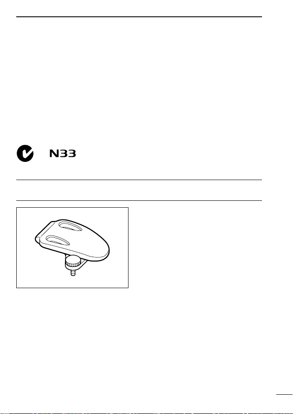
This device complies with Standard Australia
Specification No. AS/NZS4365-1996.
SUPPLIED ACCESSORY
• Belt clip . . . . . . . . . . . . . . . . .1
ii
Page 4

TABLE OF CONTENTS
FOREWORD . . . . . . . . . . . . . . . . . . . . . . . . . . . . . . . . . . . . . . . . . . . . i
IMPORTANT . . . . . . . . . . . . . . . . . . . . . . . . . . . . . . . . . . . . . . . . . . . . i
CAUTION . . . . . . . . . . . . . . . . . . . . . . . . . . . . . . . . . . . . . . . . . . . . . i–ii
SUPPLIED ACCESSORY . . . . . . . . . . . . . . . . . . . . . . . . . . . . . . . . . . ii
TABLE OF CONTENTS . . . . . . . . . . . . . . . . . . . . . . . . . . . . . . . . . . . iii
1 ACCESSORY . . . . . . . . . . . . . . . . . . . . . . . . . . . . . . . . . . . . . . . . . 1
2 PANELDESCRIPTION . . . . . . . . . . . . . . . . . . . . . . . . . . . . . . . . 2–4
‘ Switches, controls, keys and connectors . . . . . . . . . . . . . . . . 2–3
‘ Function display . . . . . . . . . . . . . . . . . . . . . . . . . . . . . . . . . . . . . 4
3 BATTERY PACK . . . . . . . . . . . . . . . . . . . . . . . . . . . . . . . . . . . . . 5–7
‘ Installing batteries in the battery case . . . . . . . . . . . . . . . . . . . . 5
‘ Battery pack charging . . . . . . . . . . . . . . . . . . . . . . . . . . . . . . . . . 6
‘ Battery pack life . . . . . . . . . . . . . . . . . . . . . . . . . . . . . . . . . . . . . 6
‘ Battery pack CAUTION . . . . . . . . . . . . . . . . . . . . . . . . . . . . . . . 6
‘ Charging connections . . . . . . . . . . . . . . . . . . . . . . . . . . . . . . . . . 7
4 BASIC OPERATION . . . . . . . . . . . . . . . . . . . . . . . . . . . . . . . . . . 8–9
‘ Power ON . . . . . . . . . . . . . . . . . . . . . . . . . . . . . . . . . . . . . . . . . . 8
‘ Adjusting the volume . . . . . . . . . . . . . . . . . . . . . . . . . . . . . . . . . 8
‘ Selecting the operating channel . . . . . . . . . . . . . . . . . . . . . . . . . 9
5 RECEIVE AND TRANSMIT . . . . . . . . . . . . . . . . . . . . . . . . . . . 10–11
6 REPEATER OPERATION . . . . . . . . . . . . . . . . . . . . . . . . . . . . . . . 12
7 SCAN FUNCTION . . . . . . . . . . . . . . . . . . . . . . . . . . . . . . . . . . . . . 13
8 GROUP MODE (CTCSS) . . . . . . . . . . . . . . . . . . . . . . . . . . . . 14–15
‘ Setting the group code . . . . . . . . . . . . . . . . . . . . . . . . . . . . . . . 14
9 RING FUNCTION . . . . . . . . . . . . . . . . . . . . . . . . . . . . . . . . . . . . . 16
‘ Smart-Ring . . . . . . . . . . . . . . . . . . . . . . . . . . . . . . . . . . . . . . . . 16
‘ Call-Ring . . . . . . . . . . . . . . . . . . . . . . . . . . . . . . . . . . . . . . . . . . 16
10 OTHER FUNCTIONS . . . . . . . . . . . . . . . . . . . . . . . . . . . . . . 17–22
‘ Initial set mode . . . . . . . . . . . . . . . . . . . . . . . . . . . . . . . . . . 17–19
‘ ATS (Automatic transponder system) . . . . . . . . . . . . . . . . . . . . 20
‘ Auto power save . . . . . . . . . . . . . . . . . . . . . . . . . . . . . . . . . . . . 20
‘ LCD backlight . . . . . . . . . . . . . . . . . . . . . . . . . . . . . . . . . . . . . . 20
‘ Low battery indicator . . . . . . . . . . . . . . . . . . . . . . . . . . . . . . . . 21
‘ Resetting the transceiver . . . . . . . . . . . . . . . . . . . . . . . . . . . . . 21
‘ Optional HM-75Afunctions . . . . . . . . . . . . . . . . . . . . . . . . . . . . 22
11 OPTIONS . . . . . . . . . . . . . . . . . . . . . . . . . . . . . . . . . . . . . . . . . . . 23
12 SPECIFICATIONS . . . . . . . . . . . . . . . . . . . . . . . . . . . . . . . . . 24–25
‘ Channel number and group number . . . . . . . . . . . . . . . . . . . . 25
13 WARRANTY . . . . . . . . . . . . . . . . . . . . . . . . . . . . . . . . . . . . . 26–27
iii
Page 5
ACCESSORY
‘‘
Accessory attachment
D Belt clip
Attach the belt clip using the
supplied screw.
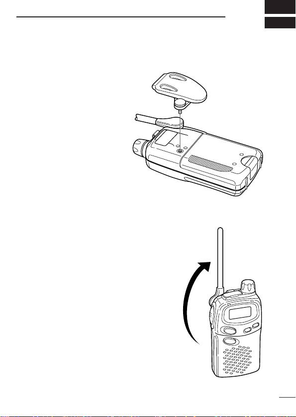
D Antenna adjustment
Adjust the antenna position as shown in
the diagram.
Keep the jack cover attached when jacks
are not in use to protect from water, dust,
etc.
1
1
Page 6
2
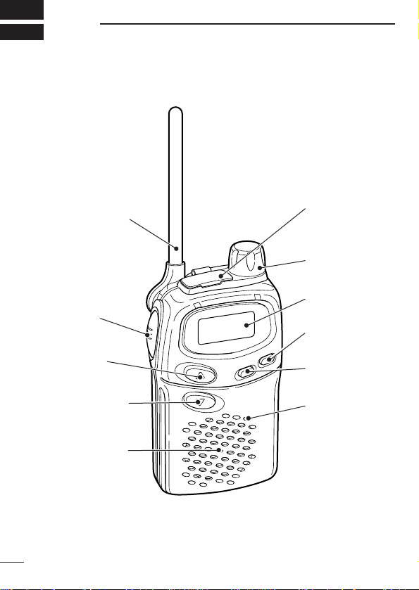
q ANTENNA
!1 SP/MIC
JACKS
!0 [VOL]
o FUNCTION
DISPLAY
i [POWER]
u [MODE]
y MIC
w [PTT]
e [UP/Y]
r [DOWN/Z]
t SPEAKER
‘‘
PANEL DESCRIPTION
Switches, controls, keys and
connectors
2
Page 7

PANELDESCRIPTION
q ANTENNA
Extend the antenna completely when using the transceiver.
• The antenna collapses completely into the transceiver body for carrying purposes.
• The antenna can be adjusted 90 degrees from the regular position
when operating the transceiver in a horizontal position.
w PTT SWITCH [PTT]
• Push and hold to transmit; release to receive.
e CHANNEL UP SWITCH [UP/Y]
• Push to change the operating channel up.
• Push and hold to increment the operating channel continuously.
• While scanning, changes scanning direction. (p. 13)
r CHANNEL DOWN SWITCH [DOWN/Z]
• Push to change the operating channel down.
• Push and hold to decrement the operating channel continuously.
• While scanning, changes scanning direction. (p. 13)
t SPEAKER
y MICROPHONE [MIC]
u MODE SWITCH [MODE]
• Push to switch between Group mode and Normal mode. (p. 14)
• Push and hold for 1 sec. to open squelch; push and hold for 1 sec.
to close it again. (p. 8)
i POWER SWITCH [POWER]
• Push to turn the power ON; push for 1 sec. to turn the power OFF.
• Continue to hold [POWER] down for 2 sec. after power ON to turn
the lock function ON and OFF. (p. 18)
• Push to switch between repeater and simplex operation. (p. 12)
o FUNCTION DISPLAY (p. 4)
!0 VOLUME CONTROL [VOL]
Rotate clockwise to increase, and counterclockwise to decrease volume.
!11 EXTERNAL SPEAKER AND MICROPHONE JACKS
Connect an optional speaker-microphone or headset, if desired.
2
3
Page 8

2
q
w
e
r
t
u
i
o!0 !1
y
PANELDESCRIPTION
‘‘
Function display
q TRANSMIT INDICATOR
Appears while transmitting.
w BUSY INDICATOR
Appears while receiving a signal or when the squelch is open.
e KEY LOCK INDICATOR (p. 18)
Appears during key lock function ON.
r REPEATER INDICATOR (p. 12)
Appears when repeater operation is selected.
t AUTO POWER OFF INDICATOR(p. 17)
Appears while the auto power off function is ON.
y LOW BATTERY INDICATOR (p. 21)
Appears or flashes when battery power has decreased to a specified level.
u PTT HOLD INDICATOR (p. 19)
• Appears when the “PTT hold” function is turned ON.
• Flashes while transmitting.
i ANSWER BACK INDICATOR (p. 20)
• Appears when you and your group are in the conversation area.
• Flashes when you or your group are out of the conversation area.
o POWER ON INDICATOR
Appears while the power is ON.
!0 CHANNEL NUMBER INDICATOR
Indicates operating channel number.
!1 GROUP NUMBER INDICATION (p. 14)
One of 01 to 38 appears while the Group function is turned ON.
4
Page 9
BATTERY PACK
‘‘
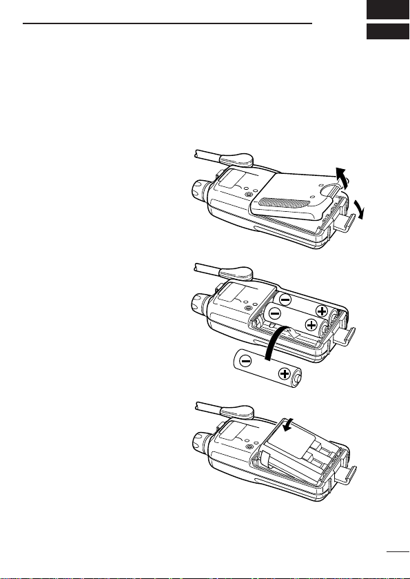
Installing batteries in the battery
3
case
Install 3 AA size alkaline, dry cell batteries or the optional BP-202
BATTERY PACK
q Remove the battery case
cover from the transceiver.
as illustrated below.
w Install 3
dry cells, or the BP-202.
• Be sure to observe the
NOTE: Keep battery contacts
clean. It’s a good idea to clean
battery terminals once a week.
×AA size alkaline,
correct polarity.
BP-202
5
Page 10

BATTERYPACKS
3
‘‘
Battery pack charging
The optional BP-202
batteries and can be charged approx. 300 times. Charge the battery
pack before first operating the transceiver or when the battery pack
becomes exhausted.
If you want to be able to charge the battery pack more than 300
times, the following points should be observed:
1. Avoid overcharging. The charging period should be less than 48
hours.
2. Use the battery until it becomes almost completely exhausted
under normal conditions. We recommend battery charging just
after transmitting becomes impossible.
‘‘
Battery pack life
If your battery pack seems to have no capacity even after being
fully charged, completely discharge it by leaving the power ON all
day. Then, fully charge the battery pack again.
If the battery pack still does not retain a charge (or very little), a new
battery pack must be purchased.
‘‘
Battery pack CAUTION
NEVER short the terminals of the battery pack (or charging termi-
nals of the transceiver). Also, current may flow into nearby metal
objects, so be careful when placing battery packs (or the transceiver) in handbags, etc. Simply carrying with metal objects may
cause a short circuit. This will damage not only the battery pack but
also the transceiver.
BATTERY PACK
includes rechargeable Ni-Cd
6
Page 11

BATTERYPACKS
*
‘‘
Charging connections
D Rapid charging with the BC-119+AD-89
q Insert the optional AD-89
charging slot of the BC-119.
w Insert the battery pack, either by itself or attached to the trans-
ceiver, into the charger.
DESKTOP CHARGER ADAPTER
into the
3
IC-40Jr
*NOTE: Put the Ni-Cd
battery adapter into the
AD-89 rear slot when
the BP-202 is attached
to the transceiver.
AC adapter
BP-202
AD-89
BC-119
7
Page 12

‘‘
Busy indicator
appears.
w
q e
➥ Push [POWER] for 1sec. to turn
‘‘
q Push [MODE] for 1 sec. to open
w Adjust the audio to a suitable level
e Push [MODE] for 1sec. to close
✔
A squelch circuit allows you to mute undesired noise while receiving no signal and emit audio while receiving signals.
This provides quiet standby. The [
squelch setting. This is useful to listen to weak signals that do
not open the squelch.
4
BASIC OPERATION
Power ON
the power ON.
• The power on indicator and operating channel number appear in
the display.
Adjusting the volume
the squelch.
• The busy indicator appears in the
display while the squelch is open.
using [VOL].
the squelch.
What is squelch
?
MODE] key changes the
8
Page 13

BASIC OPERATION
‘‘
Selecting the operating channel
Push [UP/Y] or [DOWN/Z] keys several times until the desired operating
channel number appears in the display.
• While pushing and holding [UP/Y]
or [DOWN/Z] keys, the displayed
channel changes continuously until
channel number “1” appears.
• When the displayed channel stops
at channel number “1”, a confirmation beep is emitted.
NOTE:
• The transceiver has 40 operating frequency channels.
• The selected channel is memorised when you turn off the
transceiver.
• The transceiver has an auto power save function to conserve
the battery power. The power save function activates automatically when no signal is received for 5 sec., or 5 sec. after key
operation is completed.
4
9
Page 14

q Push [MODE] for 1 sec. to open
Busy indicator
appears.
w
e Push and hold [PTT] to transmit
r Release [PTT] to return to receive.
5
RECEIVE AND TRANSMIT
the squelch.
• Adjust volume to the desired
audio level. (See p. 8)
Select a desired operating channel.
When a signal is received:
• “ ” appears in the display.
• Squelch opens and audio is emitted from the speaker.
• Further adjustment of [VOL] may
be necessary at this point.
then speak into the microphone.
• Do not hold the transceiver too
close to your mouth or speak too
loudly. This may distort the signal.
• The transmit indicator “ ” appears in the display.
Time-Out Timer (TOT)
The transceiver has a time-out timer function. This function prevents continuous, extended transmissions. This timer turns the
transmission OFF 3 min. after it starts.
A warning beep sounds 10 sec. before the limit is reached, and
the time-out timer turns OFF the transmission automatically. Another beep sounds to announce the end of the transmission.
10
Page 15

RECEIVE AND TRANSMIT
✔
Talk Range
The IC-40Jr is designed to maximize performance and improve
transmission range in the field. However, the single most important factor in transmit range is your surrounding environment.
These radios are “line of sight” radios and as such, transmission
range is influenced by the degree to which you can “see” the
other communicating party. Large concrete structures and heavy
foliage or transmission from inside a building or vehicle will reduce your talk range.
• Optimal range : wide, open areas free of obstructions.
• Medium range : large buildings or trees blocking your line of
sight.
• Minimum range : mountainous areas or areas of heavy foliage.
5
11
Page 16

6
w
Repeater
indicator
appears.
While receiving While transmitting
A repeater amplifies received signals and re-transmits them on a
different channel, allowing you to communicate over greater distances with improved reliability. When using a repeater, the transmit
channel is shifted from the receive channel by 30 channels. Please
ask you dealer regarding repeater availability in your local area.
q
w Push [POWER] momentarily to set repeater mode.
e Push and hold [PTT] to transmit.
REPEATER OPERATION
Push [UP/Y] or [DOWN/Z] to select the desired channel from 1 to 8.
• If group code appears next to the
operating channel number, push
[MODE], then select “ -–– ” with
[UP/Y] or [DOWN/Z] to cancel
the group mode (p. 14).
RWARNING!
As group mode is not compatible with repeater operation, no
audio will be heard.
• “RPT” appears in the display.
• The duplex setting affects the selected channel only and the
setting is retained after channel selection.
• The displayed channel automatically changes to the transmit
channel (repeater input channel).
12
r Release [PTT] to receive.
t To cancel the duplex setting, push [POWER] momentarily on the
desired channel.
Page 17

SCAN FUNCTION
CH 1 CH 2
CH 40
CH 5 CH 4
CH 3
Scanning is an efficient way to locate signals quickly over all channels. Select scan resume condition in advance, using Initial Set
Mode (p. 18)
7
D Starting the scan
➥ While pushing [UP/Y], push
[DOWN/Z] to start the scan.
• “-” flashes.
• While pushing [DOWN/Z], pushing [UP/Y] also starts the scan.
• Push [DOWN/Z] or [UP/Y] to
change the scanning direction or
resume the scan manually.
• To cancel the scan, push
[DOWN/Z] (or [UP/Y]) while
[UP/Y] (or [DOWN/Z]) is pushed,
or push [PTT].
13
Page 18

8
‘‘
The IC-40Jr is equipped with 38 group codes. Group mode operation provides communication with silent standby since you will only
receive calls from group members using the same group number.
First of all, set the same group code number for all group member’s
transceivers.
To turn ON the group mode operation:
q Push [MODE] to enter set mode.
w Push [UP/Y] or [DOWN/Z] to select the
e Push [MODE] to set the group code num-
To cancel the group mode operation:
q Push [MODE] to enter set mode.
w Push [UP/Y] or [DOWN/Z] to select “ - –– ”
e Push [MODE] to cancel the group mode.
GROUP MODE (CTCSS)
Setting the group code
• Operating channel number disappears
and “ -–– ” (group mode OFF) appears in
the display.
desired code number.
ber.
• Operating channel number disappears
from the display.
(group mode OFF).
w
w
q e
14
IMPORTANT!: Before transmitting, make sure the channel you
will operate with the group mode is clear by pushing [MODE] for
1 sec., to prevent interference to other stations.
NOTE: Only stations with the same group channel number can
be heard during group mode operation, even when the busy indicator appears in the display.
Page 19

GROUP MODE (CTCSS)
✔
What is CTCSS (Continuous Tone Coded Squelch System) GROUP MODE ?
CTCSS (Continuous Tone Coded Squelch System) GROUP
MODE allows communication with silent stand by. Only signals
containing your group code can open the squelch.
This conveniently eliminates unwanted audio and is useful in
group activities or security related activities where unwanted output can be a problem. Note that CTCSS group mode is not private— anyone can receive your calls.
The IC-40Jr is equipped with 38 tone codes for CTCSS GROUP
MODE use. Selecting a code applies to all 40 operating channels.
Each push of [PTT] superimposes your group code over your
transmit signal; and, only signals containing the same code can
open your squelch. To temporarily hear all signals (including
noise) push and hold [MODE]. Do not use CTCSS GROUP
MODE if you want to be able to hear all signals on the channel.
D CTCSS code table
Code Freq. Code Freq. Code Freq. Code Freq.
01 67.0 11 97.4 21 136.5 31 192.8
02 71.9 12 100.0 22 141.3 32 203.5
03 74.4 13 103.5 23 146.2 33 210.7
04 77.0 14 107.2 24 151.4 34 218.1
05 79.7 15 110.9 25 156.7 35 225.7
06 82.5 16 114.8 26 162.2 36 233.6
07 85.4 17 118.8 27 167.9 37 241.8
08 88.5 18 123.0 28 173.8 38 250.3
09 91.5 19 127.3 29 179.9 --- OFF
10 94.8 20 131.8 30 186.2
(unit: Hz)
8
15
Page 20

9
‘‘
The Smart-Ring function has an answer back feature. This allows
you to confirm whether or not a call has reached the receiving party .
q Set the same group code number for all
w
e Release the [PTT].
r Push [PTT] to answer and to stop the beeps and flashing.
‘‘
Sends the ring tones during transmit mode.
➥ While pushing [PTT], push [DOWN/Z]
to send a ring tone.
RING FUNCTION
Smart-Ring
of your group transceivers. (See p. 14)
While pushing [PTT], push [UP/Y].
• A beep is emitted and “ ” flashes in
the display.
• When a member of your group answers your call, the transceiver emits
beep tones for 10 sec. and “ ” stops
flashing.
• When no answer comes back, the transceiver emits short faint
beep tones.
NOTE: This function is available only when the called station has set
the same group number and the same operating channels as you.
Call-Ring
• The ring tone is emitted while pushing
[DOWN/Z].
• The microphone signal is automatically
cut while pushing [DOWN/Z].
16
Page 21

OTHER FUNCTIONS
w q
w
q
‘‘
Initial set mode
Initial set mode is accessed at power ON and allows you to set seldom changed settings. In this way you can “customise” the transceiver operations to suit your preferences and operating style.
10
D Auto power OFF
This function sets the transceiver to
automatically turn OFF after 2 hours
has elapsed from the last key operation.
q While pushing [MODE], push
[POWER] ON to switch the function ON or OFF.
w “ ” appears in the display.
• “Auto power OFF” function retains its setting after power OFF.
D Ring tone type
You can select the ring tone from one
of 10 sounds.
q While pushing
[POWER] ON.
w Push [
UP/Y] or [DOWN/Z] to se-
lect the ring sound.
[UP/Y], push
D Beep tones ON/OFF
Confirmation beep tones normally
sound when you push a key. These
can be turned ON or OFF.
➥ While pushing [
[POWER].
DOWN/Z], push
17
Page 22

OTHER FUNCTIONS
Lock indicator
appears.
w q
w q
q
Timer scan Pause scan
10
D Lock function
This function electronically locks all keys and switches to prevent
accidental channel changes and function access.
➥ Continue to hold [POWER] down
for 2 sec. after power ON to turn
the lock function ON and OFF.
“ ” appears in the display.
- Only [POWER], [MODE] and
[PTT] are functional.
- The Ring function is also available. (See p. 16)
D Scan resume condition
The scan resume condition can be selected from timer and pause
scan. When the pause scan (P-05) is selected, this pauses the
scan until 5 sec. has passed after the signal has disappeared.
When the timer scan (t-05) is selected, this pauses for 5 sec. and
then resumes, even if a signal is being received on the channel.
q While pushing both [UP/Y] and [DOWN/Z], turn the power ON .
w Push [UP/Y] or [DOWN/Z] to se-
lect scan resume condition from
t-05 and P-05.
(Default setting is t-05.)
18
Page 23

OTHER FUNCTIONS
PTT hold
indicator
appears.
10
D PTT hold function
This function frees you from having to constantly push [PTT] during
conversation.
q While pushing [PTT], turn the
power ON to switch the PTT hold
function ON and OFF.
” appears in the display when
•“
≈
the PTT hold function is activated.
• During group mode operation, the
PTT hold function cannot be activated. Push [MODE] to cancel
the group mode (p. 14).
w Push [PTT] to transmit.
• “ ” appears and “
the display.
• Once [PTT] is pushed, it is not necessary to hold [PTT] any
longer during transmission.
• The transmission is automatically cancelled when the time-out
timer is activated (p. 10).
e Push [PTT] to return to receive.
• “ ” disappears and “
NOTE: The PTT hold function cannot be activated with the external speaker-microphone’s [PTT].
” flashes in
≈
” stops flashing.
≈
19
Page 24

OTHER FUNCTIONS
appears
10
‘‘
ATS (Automatic Transponder System)
This allows you to confirm whether or not a call has reached the receiving party even if the operator is temporarily away from the
transceiver. No “Ring” tone is emitted with this function.
➥ Push [MODE], while [PTT] is ON to
turn the function ON/OFF.
• “ ” appears in the display.
• The transceiver starts to send a
search signal every 60 sec.
- When the transceiver receives
an answer back signal, “ ”
stays on the display until the
next search transmit.
- If no reply is received, “ ”
flashes until the next search transmit.
NOTE: The above setting is for the calling station only. Acalled
party automatically sends an answer back signal without any
presettings.
All IC-40Jr’s operating on the same operating channel will answer back to your call in your communication area.
‘‘
Auto power save
➥ The power save function reduces the current drain to conserve
battery power.
- The function automatically starts when no operation is performed or no signal is received for 5 sec.
‘‘
LCD backlight
➥ Automatically lights ON for 5 sec. when you push any key, ex-
cept [PTT].
20
Page 25

OTHER FUNCTIONS
‘‘
Low Battery indicator
➥ Appears when the battery is nearing ex-
haustion.
• A warning beep is emitted at power ON.
➥ Appears and flashes when battery replace-
ment is necessary.
‘‘
Resetting the transceiver
Initialise the operating conditions before using the transceiver for
the first time, or if the function display shows erroneous information.
➥ While pushing [
[MODE], push [POWER] ON to
initialise the transceiver.
CAUTION: Resetting the transceiver returns all settings to their
defaults.
DOWN/Z] and
10
21
Page 26

OTHER FUNCTIONS
A
OFF ON
LOCK
B
Lock switch:
Locks all
switches
except [PTT]
Earphone
jack
PTT switch
10
‘‘
Optional HM-75A functions
The optional HM-75Aallows you to remotely select operating channels, open the squelch, etc. The switches on the HM-75A function
as follows.
CAUTION: When connecting the HM-75A to the transceiver,
make sure that power to the transceiver is turned OFF, otherwise the transceiver may malfunction.
D Switch action
SWITCH
A
B
UP
DOWN
NORMAL
Smart-Ring
Open squelch
Change the operating channel
number up.
Change the operating channel
number down.
While holding [PTT]
No function
No function
Smart-Ring
Call-Ring
22
Page 27

OPTIONS
HM-46
HM-75A
HM-54
HS-85 HEADSET
• PTT switch
• VOX
•One-touch PTT for
hands-free operation
Remote control
capability.
(see p. 22 for details)
CP-17L
OPC-515L
11
D Battery pack
BP-202
3.6V/700 mAh rechargeable battery pack, allows approx. 10 hours
of operation. (pgs. 6–7)
Ni-Cd BATTERY PACK
D Charger
BC-119
Rapidly charge battery packs in 1 to 1.5 hrs. An AC adapter is
packed with the BC-119. The AD-89 must be used with the BC-119
for charging the battery pack. The CP-17L
CABLE WITH NOISE FILTER
used instead of the supplied AC adapter. (p. 7)
DESKTOP CHARGER
+ AD-89
or OPC-515L
DESKTOP CHARGER ADAPTER
CIGARETTE LIGHTER
DC POWER CABLE
can be
D Speaker-microphones
D Cables (for the BC-119)
23
Page 28

12
SPECIFICATIONS
GENERAL
• Frequency coverage : 40 UHF C.R.S. channels
(476.425–477.400 MHz)
• Mode : F3E (FM)
• Frequency stability : ±3.0 kHz
• Frequency resolution : 25 kHz
• Power supply requirement: 4.5 V (AA × 3) or BP-202
• Current drain : Less than 500 mA
• Battery life (Tx:Rx:Stand-by=1:1:8):
3 Alkaline cells approx. 28 hours
Optional BP-202 approx. 10 hours
• Operating temp. range : 0˚C to +55˚C
• Number of CTCSS freq. : 38
• Dimensions : 55.5(W)×102.5(H)×26.5(D) mm
(projections not included)
• Weight : 180 g (including 3 AAbatteries)
TRANSMITTER
• Output power : 500 mW ±20% (at 4.5 V DC)
• Maximum deviation : Less than ±5.0 kHz
• Spurious emissions : Less than –30 dBm
• Ext. mic. connector : 3-conductor 2.5 (d) mm/2.2 kΩ
RECEIVER
• Receive system : Double-conversion superheterodyne
• Sensitivity : Less than 0.2 µV (12 dB SINAD)
• Selectivity : More than 12 kHz/–6 dB
Spurious and image rejection
•
• Adjacent Ch. rejection : More than 40 dB
• Intermodulation rejection : More than 40 dB
• Audio output power : More than 100 mW at 10% distortion
(at 4.5 V DC) with an 8 Ω load
• Ext. speaker connector : 2-conductor 3.5 (d) mm/8 Ω
All stated specifications are subject to change without notice or obligation.
24
: More than 40 dB
Page 29

SPECIFICATIONS
12
ï Channel frequency list
CH Freq. CH Freq. CH Freq. CH Freq.
1 476.425 11 476.675 21 476.925 31 477.175
2 476.450 12 476.700 22 476.950 32 477.200
3 476.475 13 476.725 23 476.975 33 477.225
4 476.500 14 476.750 24 477.000 34 477.250
5 476.525 15 476.775 25 477.025 35 477.275
6 476.550 16 476.800 26 477.050 36 477.300
7 476.575 17 476.825 27 477.075 37 477.325
8 476.600 18 476.850 28 477.100 38 477.350
9 476.625 19 476.875 29 477.125 39 477.375
10 476.650 20 476.900 30 477.150 40 477.400
(Unit: MHz)
‘‘
Channel number and group number
Use this page to record your group operating channel number (p. 9)
and group channel number (p. 14) for your reference.
Operating channel number
Group code number
25
Page 30

13
WARRANTY
Icom Warranty
Icom Incorporated is proud of the technology within, and the quality of
workmanship of its products.
Icom (Australia) Pty. Ltd. , the authorised Icom Distributor, warrants this
Icom product to be free defects in material or workmanship for a period
of two years from date of purchase from an authorized Icom dealer.
Icom (Australia) Pty. Ltd. will, at its discretion, and subject to the terms
and conditions stated below, repair or replace any goods or component
part thereof which its examination shall disclose to be defective.
Unless otherwise expressly provided, any fault arising from defective
workmanship or material shall be rectified by Icom where the equipment is
returned freight prepaid to Icom at 290–294 Albert Street, Brunswick Victoria 3056 within twenty four months of the date of purchase of the
goods, proof of purchase must be presented.
This Warranty shall not apply:
(a)
To an Icom product which has failed due to improper installation,
misuse, accident, alteration or unauthorized repair or modification.
(b)If any serial number or identification place attached to the goods
has been altered, rendered illegible, or removed.
(c) If the goods have been:
(i) subject to misuse, abuse, or negligent or accidental damage;
(ii) connected to improper, inadequate or faulty power including
reverse polarity;
(iii) operated otherwise than in accordance with the instructions
furnished by Icom;
(iv)damaged by corrosion, deterioration or by abnormal temper-
atures; the influence of foreign matter or energy of physical
or chemical properties of water, steam or chemical compounds;
(v) serviced, repaired or disassembled whether wholly or in part
other than by Icom (Australia) Pty. Ltd.;
(vi)purchased from any dealer other than an authorised Icom
dealer.
(d)If no proof of purchase is presented.
26
Page 31

WARRANTY
This Warranty is in addition to the benefits conferred by Federal and
State legislation and, to the extent allowed thereunder and without in
any way limiting and implied warranty of merchantability or fitness for a
particular purpose, any liability of Icom for any loss or damage arising
from breakdown, failure to perform or illegal use is hereby expressly excluded.
13
WARRANTY SERVICE INSTRUCTION
1.If you have difficulty, send your equipment to Icom (Australia) Pty.
Ltd., preferably in the original carton, without accessories, prepaid,
with a brief explanation of the difficulty you have experienced.
2. Include accessories only if your specific situation indicates an accessory related difficulty exists, otherwise Icom (Australia) Pty . Ltd. shall
assume no liability for the loss or safe return of an accessory item.
Itemise these accessories on the note of explanation.
3. If the requested repairs or services are within the terms of the warranty, your equipment will be returned after repair, to any designated
point within Australia.
4.If the requested repairs or services are not within the terms of the
warranty, or if you fail to provide acceptable evidence of date of purchase or proof of purchase, return freight will be charged.
Model :
Date of purchase :
Serial Number :
Dealer Name :
Icom (Australia) Pty. Ltd. A.B.N. 88 006 092 575
Authorized Icom Distributor
290–294 Albert Street,
Brunswick 3056 Vic.
27
Page 32

A-5691D-1AU
Printed in Japan
© 2000 Icom Inc.
1-1-32 Kamiminami, Hirano-ku, Osaka 547-0003 Japan
 Loading...