

Page 1
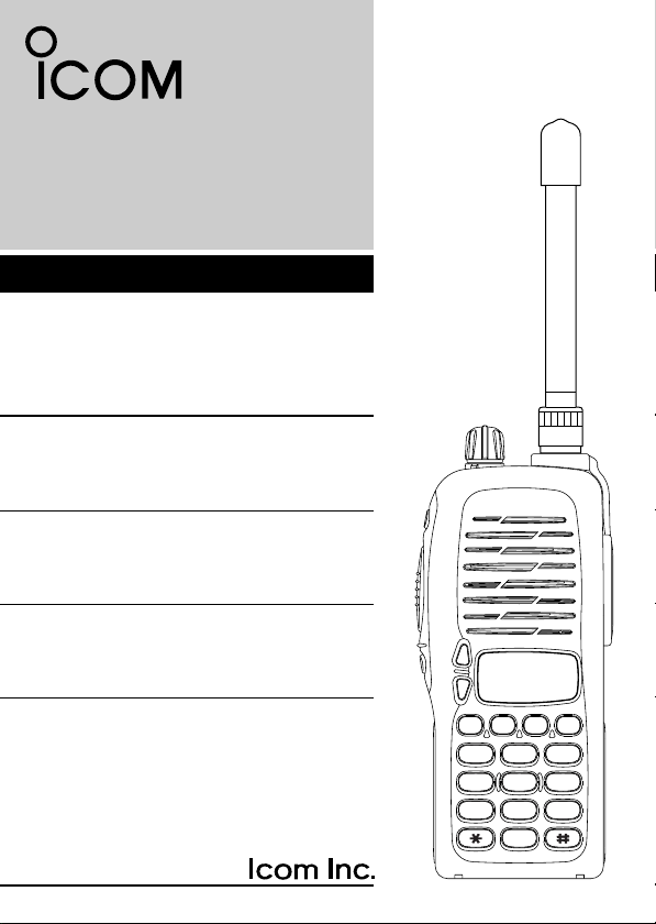
INSTRUCTION MANUAL
2
3
4
5
6
789
0
1
P0
P1
P2 P3
245 MHz FM TRANSCEIVER
i3FGX
Page 2

FOREWORD
Thank you for purchasing the IC-3FGX 245 MHz FM transceiver.
READ ALL INSTRUCTIONS carefully and completely before using
the transceiver.
SAVE THIS INSTRUCTION MANUAL–This instruction manual
contains important operating instructions for the transceiver.
IMPORTANT
R CAUTION! NEVER hold the transceiver so that the antenna is
very close to, or touching exposed parts of the body, especially the
face or eyes, while transmitting. The transceiver will perform best if
the microphone is 2 to 4 in. (5 to 10 cm) away from the lips and the
transceiver is vertical.
R CAUTION! NEVER operate the transceiver with a headset or
other audio accessories at high volume levels.
R CAUTION! NEVER short the terminals of the battery pack.
DO NOT push the PTT when not actually desiring to transmit.
AVOID using or placing the transceiver in direct sunlight or in areas
with temperatures below +14°F (–10°C) or above +122°F (+50°C).
DO NOT modify the transceiver for any reason.
KEEP the transceiver from the heavy rain, and Never immerse it in
the water. The transceiver construction is water resistant, not
water proof.
The use of non-Icom battery packs/chargers may impair transceiver
performance and invalidate the warranty.
i
Page 3

TABLE OF CONTENTS
FOREWORD . . . . . . . . . . . . . . . . . . . . . . . . . . . . . . . . . . . . . . . . . . .i
IMPORTANT . . . . . . . . . . . . . . . . . . . . . . . . . . . . . . . . . . . . . . . . . . .i
TABLE OF CONTENTS . . . . . . . . . . . . . . . . . . . . . . . . . . . . . . . . . .ii
1 PANEL DESCRIPTION . . . . . . . . . . . . . . . . . . . . . . . . . . . . . .1–3
‘ Switches, controls, keys and connectors . . . . . . . . . . . . . . .1–2
‘ Function display . . . . . . . . . . . . . . . . . . . . . . . . . . . . . . . . . . . .3
2 ACCESSORIES . . . . . . . . . . . . . . . . . . . . . . . . . . . . . . . . . . . . . .4
3 BATTERY PACKS . . . . . . . . . . . . . . . . . . . . . . . . . . . . . . . . .5–10
‘ Battery pack replacement . . . . . . . . . . . . . . . . . . . . . . . . . . . .5
‘ Battery cautions . . . . . . . . . . . . . . . . . . . . . . . . . . . . . . . . . . . .6
‘ Battery charging . . . . . . . . . . . . . . . . . . . . . . . . . . . . . . . . . .7-8
‘ Charging NOTE . . . . . . . . . . . . . . . . . . . . . . . . . . . . . . . . . . .9
‘ Battery case (Option) . . . . . . . . . . . . . . . . . . . . . . . . . . . . . .10
44 PPRROOGGRRAAMMMMAABBLLEE FFUUNNCCTTIIOONNSS .. .. .. .. .. .. .. .. .. .. .. .. .. .. .. .. .. .. .. .. ..
‘ Receiving and transmitting . . . . . . . . . . . . . . . . . . . . . . . . . . .11
5 CONVENTIONAL OPERATION . . . . . . . . . . . . . . . . . . . . . .16-18
‘ Call procedure . . . . . . . . . . . . . . . . . . . . . . . . . . . . . . . . . . . .17
‘ Tx code channel selection . . . . . . . . . . . . . . . . . . . . . . . . . . .18
‘ Manual 5-tone codes . . . . . . . . . . . . . . . . . . . . . . . . . . . . . . .18
‘ Transmitting notes . . . . . . . . . . . . . . . . . . . . . . . . . . . . . . . . .18
6 OTHER FUNCTIONS . . . . . . . . . . . . . . . . . . . . . . . . . . . . . . . . .19
‘ DTMF pager/Code squelch . . . . . . . . . . . . . . . . . . . . . . . . . .19
7 MAINTENANCE . . . . . . . . . . . . . . . . . . . . . . . . . . . . . . . . . . . . .20
‘ Optional UT-108/UT-109 and UT-110 installation . . . . . . . . .20
8 CLONING . . . . . . . . . . . . . . . . . . . . . . . . . . . . . . . . . . . . . . . . . .21
9 CHANNEL LIST . . . . . . . . . . . . . . . . . . . . . . . . . . . . . . . . . . . . .22
10 SPECIFICATIONS . . . . . . . . . . . . . . . . . . . . . . . . . . . . . . . . . .23
11 OPTIONS . . . . . . . . . . . . . . . . . . . . . . . . . . . . . . . . . . . . . . .24-25
12 MEMO . . . . . . . . . . . . . . . . . . . . . . . . . . . . . . . . . . . . . . . . .26-28
11-15
ii
Page 4
1
2
3
4
5
6
789
0
1
P0
P1
P2 P3
q
w
e
r
t
y
u
!0
i
o
Speaker
Mic
‘‘
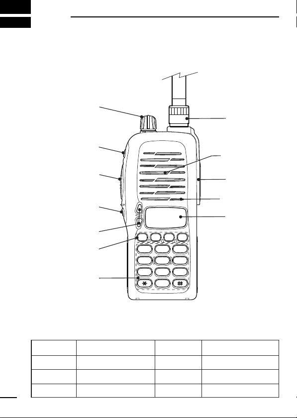
PANEL DESCRIPTION
Switches, controls, keys and connectors
DD
Programmable key reference
S1 (Red)
S2 (Black)
YY
ZZ
1
P0
P1
P2
P3
Page 5

PANEL DESCRIPTION
q VOLUME CONTROL [OFF/VOL]
Turns power ON and adjusts the audio level.
w DEALER-PROGRAMMABLE KEY [S1 (Red)]
e PTT SWITCH [PTT]
Push and hold to transmit; release to receive.
r DEALER-PROGRAMMABLE KEY [S2(Black)]
t UP/DOWN KEYS [YY]/[ZZ]
• Push to select the operating channel.
y DEALER-PROGRAMMABLE KEYS [P0]/[P1]/[P2]/[P3]
Can each be programmed for one of several functions by your
Icom Dealer.
u 10-KEY PAD
Used to enter DTMF codes, the operating channel, etc.
i ANTENNA CONNECTOR (BNC)
Connects the supplied antenna.
o [SP]/[MIC] JACK
Connect optional speaker-microphone.
!0 FUNCTION DISPLAY
Displays the following information:
• CH number.
• 5-tone indication.
• Low-battery indication.
• DTMF numbers.
• Low-power indication.
• Skip-Ch indication.
• Audible indication.
NOTE: Above functions depend on pre-setting.
1
2
Page 6
1
!0
q
w
e
r
tyui
o
PANEL DESCRIPTION
‘‘
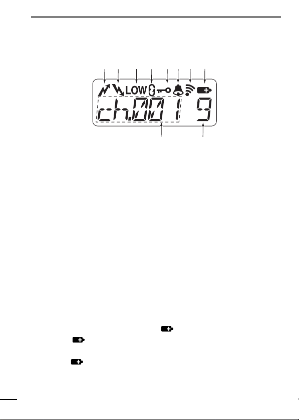
Function display
q TRANSMIT INDICATOR
Appears during PTT on.
w BUSY INDICATOR
Appears while receiving a signal or when the squelch is open.
e LOW POWER INDICATOR (p. 12)
Appears when low output power is selected.
r SCRAMBLER INDICATOR
Appears while the scrambler function is operating.
t KEY LOCK INDICATOR (p. 11)
Appears during key lock function ON.
y BELL INDICATION
Appears or blinks when the optional 5Tone call is received.
u AUDIBLE INDICATOR
Appears when monitor function is turned ON. (CTCSS and DTCS
mutes are released.)
i LOW BATTERY INDICATOR [ ]
o S-meter
!0 ALPHANUMERIC INDICATOR
3
-When appears, battery
capacity is low and transmitting is impossible.
-When flashes, battery capacity is nearly exhausted.
Show the received signal strength
Page 7
ACCESSORIES
q
w
e
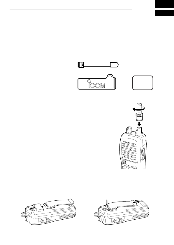
To attach the belt-clip
To release the belt-clip
‘‘
Accessory attachment
D Supplied accessories
The transceiver comes supplied with the following accessories.
q Flexible antenna
w Belt clip
e 2251 OPT sheet
(See p. 26)
D Antenna
The antenna screws onto the transceiver as
illustrated right.
Keep the jack cover attached when jacks are
not in use to avoid bad contacts.
D Belt clip
Attach the belt clip to the transceiver as illustrated below.
2
4
Page 8
3
yrettaB
kcap
egatloV yticapaC
doirepgnigrahC
gnitarepO
*doirep
1
BC-137
ro911-CB
121-CB
49-DAhtiw
802-PB
AArofesacyretta
B
)6R( × enilakla6
A/N
V2.7
srh51srh5.1srh8
012-PB V2.7
0561
hAm
srh51srh0.2srh11
1100
mAh
BP-209R
‘‘
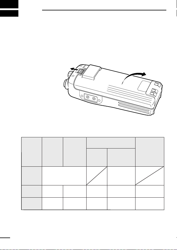
Before replacing the battery pack, the volume control MUST be rotated fully counterclockwise, until a click is heard, to turn the power
OFF.
• Push the battery
release forward,
then pull the battery pack upward
with the transceiver facing
you.
DD
BATTERY PACKS
*1Operating periods are calculated under the following conditions;
Tx : Rx : standby =5 : 5 : 90
* Operating period depends on alkaline cells used.
5
BATTERY PACKS
Battery pack replacement
Page 9

BATTERY PACKS
‘‘
Battery cautions
• CAUTION! NEVER short terminals of the battery pack (or charg-
ing terminals of the transceiver). Also, current may flow into
nearby metal objects such as a necklace, so be careful when placing battery packs (or the transceiver) in handbags, etc.
Simply carrying with or placing near metal objects such as a necklace, etc. causes shorting. This will damage not only the battery
pack, but also the transceiver.
• NEVER incinerate used battery packs. Internal battery gas may
cause an explosion.
• NEVER immerse the battery pack in water. If the battery pack be-
comes wet, be sure to wipe it dry BEFORE attaching it to the
transceiver.
• Clean the battery terminals to avoid rust or miss contact.
• Keep battery contacts clean. It’s a good idea to clean battery ter-
minals once a week.
If your battery pack seems to have no capacity even after being
charged, completely discharge it by leaving the power ON
overnight. Then, fully charge the battery pack again. If the battery
pack still does not retain a charge (or only very little charge), a new
battery pack must be purchased. (P. 9)
3
6
Page 10
BATTERY PACKS
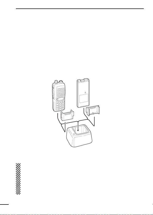
BC-119
Check orientation
for correct charging. (Insert together with AD-94.)
Turn power
OFF.
AD-94
AD-94
3
‘‘
Battery charging
D Rapid charging with the BC-119+AD-94
The optional BC-119 provides rapid charging of optional battery
packs.
The following are additionally required:
• One AD-94.
• An AC adapter (may be supplied with the BC-119 depending on
version).
When using the BC-119 in a vehicle: If the charge indicator
flashes orange, the vehicle battery voltage is low and charging
may not be performed. Check the vehicle battery voltage in this
case. If the charge indicator flashes red, there may be a problem with the battery pack (or charger). Re-insert the battery
pack or contact your dealer.
7
Page 11
BATTERY PACKS
M
U
L
T
I-C
H
A
R
G
E
R
AC adapter
(purchased
separately)
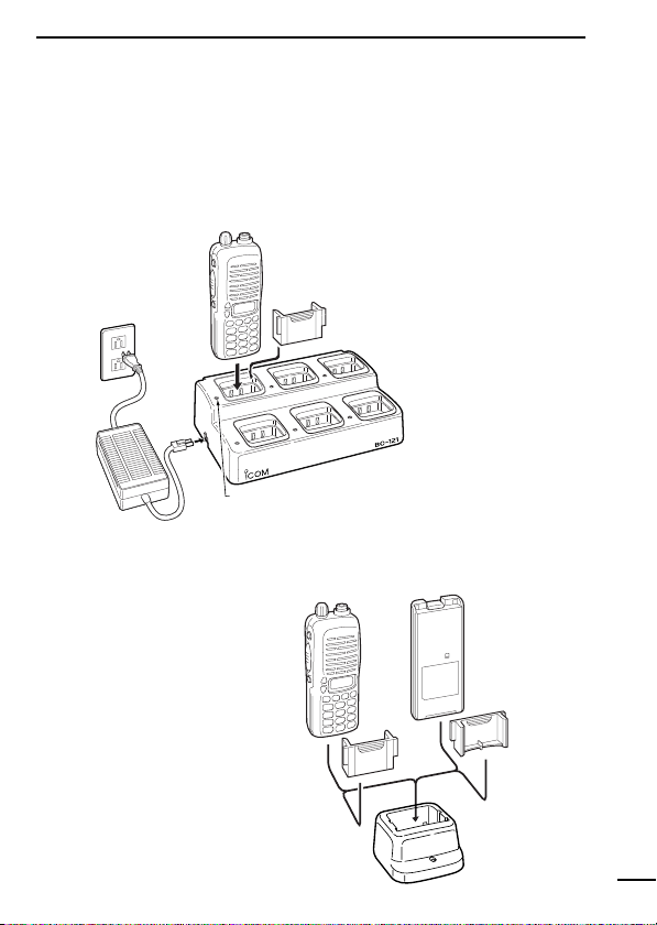
Charge indicator
(each indicator functions independently)
Turn power OFF.
Check orientation
for correct charging.
(Insert together with charging
adapter.)
Turn power OFF.
BC-137
D Rapid charging with the BC-121+AD-94
The optional BC-121 allows up to 6 battery packs to be charged simultaneously. The following are additionally required.
• Six AD-94s.
• An AC adapter (may be supplied with the BC-121 depending on
version).
D Regular charging with the BC-137
The optional BC-137 provides regular charging of
optional battery pack with/
without transceiver.
The following is additionally
required:
• An optional AC adapter.
(A charger adapter is supplied with BC-137.)
3
8
Page 12

BATTERY PACKS
3
‘‘
Charging NOTE
Prior to using the transceiver for the first time, the battery pack must
be fully charged for optimum life and operation.
• Recommended temperature range for charging:
+10°C to +40°C (50°F to 140°F).
• Use the supplied charger or optional charger (BC-119/BC-121 for
rapid charging, BC-137 for regular charging) only. NEVER use
other manufacturers’ chargers.
The optional BP-209R or BP-210 battery packs include rechargeable Ni-Cd(Ni-MH: BP-210) batteries and can be charged approx.
300 times. Charge the battery pack before first operating the transceiver or when the battery pack becomes exhausted.
If you want to charge the battery pack more than 300 times, the following points should be observed:
• Avoid over charging. The charging period should be less than 48
hours.
• Use the battery until it becomes almost completely exhausted
under normal conditions. We recommend battery charging after
transmitting becomes impossible.
DD
Battery pack life
When the operating period becomes extremely short even after
charging the battery pack fully, a new battery pack is needed.
9
Page 13

BATTERY PACKS
‘‘
Battery case (Option)
When using a BP-208 OPTIONAL BATTERY CASE attached to the
transceiver, install 6 AA (R6) size alkaline batteries as illustrated
below.
DD
CAUTIONS
• Use ALKALINE batteries only.
• Make sure all battery cells are the same brand, type and ca-
pacity.
• Never mix old and new batteries.
Either of the above may cause a fire hazard or damage the
transceiver. If ignored.
• Never incinerate used battery cells since internal battery gas
may cause them to rupture.
• Never expose a detached battery case to water.
If the battery case gets wet, be sure to wipe it dry before using.
3
10
Page 14

4
‘‘
In the following explanations, programmable function names are
bracketed, the specific switch used to activate the function depends
on programming.
DD
KEYPAD LOCK FUNCTION
This function locks access to all programmable switches (except
the switch assigned for the lock function).
:
Push and hold the [LOCK] switch for 1 sec. to toggle the lock function ON and OFF.
• “”appears while the lock function is ON.
• This function may be inhibited on some channels.
DD
PRIORITY CHANNEL
This function is used to select a pre-programmed channel at the
push of a switch.
Push the [PRIORITY] switch to select the priority channel.
• “PRIO” appears briefly, then the priority channel is automatically
selected.
DD
SCAN FUNCTION
The scan function allows you to search a pre-programmed group
of channels for signals.
PROGRAMMABLE FUNCTIONS
General
Push the [SCAN] switch to start/stop scan.
• Scan pauses on a channel when receiving a signal.
• Depending on programming, a message may appear while scan-
ning.
• “Lockout SCAN” (pre-programmed list SCAN) or “Priority SCAN”
can be pre-programmed.
• When the “Power-save function” is activated, the transceiver
11
Page 15

PROGRAMMABLE FUNCTIONS
checks all pre-programmed channels then returns to the “Powersave function” again.
DD
HIGH/LOW POWER OUTPUT
This function selects high or low power for a channel.
Push the [HIGH/LOW] switch to toggle between high and low
power.
• “LOW” appears when low output power is selected.
DD
SCRAMBLER FUNCTION (optional UT-109 #01* or UT-110 #01*
is required.)
This function provides higher communication security.
UT-109: Non-rolling type. 32 code numbers are available.
UT-110: Rolling type. 1020 (4 group × 255) code numbers are avail-
able.
Push the [SCRM] switch to toggle the function ON and OFF.
NOTE: NEVER use #02 High AF level versions, as they are not
compatible
DD
BEEP FUNCTION
This function provides confirmation beep tones when pushing
switches.
Push the [BEEP] switch to toggle the function ON and OFF.
4
12
Page 16

PROGRAMMABLE FUNCTIONS
All signals are
received
2
3
4
5
6
789
0
1
P0
P1 P2 P3
Only signals
containing
the proper
tone are
received
2
3
4
5
6
789
0
1
P0
P1 P2 P3
4
DD
MONITOR AUDIBLE FUNCTION
The monitor function allows you to open the transceiver’s squelch
manually to check whether a channel is busy or not. The transceiver has 2 conditions for receive standby:
Audible condition:
This condition mutes audio ONLY when
no carrier is present. You can receive (or
monitor) any signals on a channel.
• Push and hold the [MONI/AUDI], switch
to select the audible condition.
Any audio mute functions are cancelled
while pushing the [MONI/AUDI] switch.
Inaudible condition:
This condition mutes ALL signals except
those directed to you. Therefore you
should check a channel’s condition (busy
or not) with the monitor function before
transmitting.
• Push the [MONI/AUDI] switch momen-
tarily to select the inaudible condition.
DD
TALK AROUND
The talk around function changes duplex channels to simplex channels.
• Duplex allows you to contact your base station, repeaters, etc.
• Simplex allows you to contact other portable transceivers directly
(portable-to-portable contact).
Push the [TALK AROUND] switch one or more times to toggle the
function ON and OFF.
13
Page 17

PROGRAMMABLE FUNCTIONS
DD
DTMF TRANSMISSION
This function allows you to send a pre-programmed DTMF code to
control a repeater, open another transceiver’s squelch, etc.
Manual transmission:
Push desired digit keys in sequence while pushing [PTT].
• Pushing [PTT] may not be necessary depending on programming.
Automatic pre-programmed transmission:
q Push the [DTMF] switch to select DTMF autodial mode, then
push [Y] or [Z] to select the desired channel.
w Push the [DTMF] switch once more to send a DTMF code.
DD
DTMF RE-DIAL FUNCTION
This function allows you to transmit the last-used DTMF code at the
push of a key.
Push the [DTMF RE-DIAL] switch momentarily to activate the function.
• The previously transmitted DTMF code is automatically transmitted.
• If no code has been transmitted since turning the power ON, this
function does not activate.
DD
EMERGENCY FUNCTION
The emergency function allows you to send your ID quickly and
easily to your Base Station, etc. in case of emergency.
4
Push and hold the [EMERGENCY] switch for 1 sec. to activate the
emergency function.
• The transceiver selects a pre-programmed channel, then sends
an emergency signal to your Base Station.
• The pre-programmed channel remains selected until a control signal is received from the Base Station, or power is turned OFF.
14
Page 18

PROGRAMMABLE FUNCTIONS
4
• The emergency call is repeatedly transmitted at pre-programmed
intervals.
DD
DISPLAY LIGHTING
The function display has 3 backlight conditions.
OFF : No backlight is available.
AUTO : When any key is pushed, the backlight turns ON for 5
sec. automatically.
CONTINUOUS : Backlight turns ON continuously.
15
Page 19

CONVENTIONAL OPERATION
‘‘
Receiving and transmitting
NOTE: Transmitting without an antenna may damage the trans-
ceiver. See p.1 for antenna attachment.
Turn power ON as described on p. 1.
Receiving:
YY
q Push [
w Listen for a transmission and adjust [VOL] to a comfortable lis-
tening level.
• When no transmission is heard, push and hold monitor while
The transceiver is now set to receive desired calls on the selected
channel.
Transmitting:
Wait for the channel to become clear to avoid interference.
e While pushing and holding [PTT], speak into the microphone at a
normal voice level.
• When a tone signalling system is used, the call procedure de-
r Release [PTT] to return to receive.
IMPORTANT: To maximize the readability of your transmitted signal, pause a few sec.. after pushing [PTT], hold the microphone 10
to 15 cm from your mouth and speak at a normal voice level.
]/[ZZ] to select a channel.
adjusting [VOL] (your transceiver may not be programmed with
the monitor function).
scribed at right may be necessary.
5
16
Page 20

CONVENTIONAL OPERATION
2
3
4
5
6
789
0
1
P0
P1
P2 P3
2
3
4
5
6
789
0
1
P0
P1
P2 P3
2
3
4
5
6
789
0
1
P0
P1
P2 P3
2
3
4
5
6
789
0
1
P0
P1
P2 P3
2
3
4
5
6
789
0
1
P0
P1
P2 P3
2
3
4
5
6
789
0
1
P0
P1
P2 P3
2
3
4
5
6
789
0
1
P0
P1
P2 P3
2
3
4
5
6
789
0
1
P0
P1
P2 P3
Non-selective calling
Selective calling
5
‘‘
Call procedure
When your system employs tone signalling (excluding CTCSS and
DTCS), the call procedure may be necessary prior to voice transmission. The tone signalling employed may be a selective calling
system which allows you to call specific station(s) only and prevent
unwanted stations from contacting you.
q Select the desired Tx code channel or 5-tone code according to
your System Operator’s instructions.
• This may not be necessary depending on programming.
• Refer to the next page for selection.
w Push the call switch (assigned to one of the dealer programma-
ble switches: [P0], [P1], [P2], [P3], [S1] and [S2]).
e After transmitting a 5-tone code, the remainder of your commu-
nication can be carried out in the normal fashion.
17
Page 21

CONVENTIONAL OPERATION
‘‘
Tx code channel selection
Your radio may be programmed for Tx code channel selection. In
this case, you can choose a Tx code channel to be transmitted
when using the call function (p. 17).
Push the Tx code channel switch (assigned to one of the dealerprogrammable switches) to activate the function, then enter digits
via the keypad to select the desired Tx code channel.
• The selected code channel (containing a pre-programmed 5-tone
code) is transmitted when using the call function.
‘‘
Manual 5-tone codes
Depending on programming, you may be able to send 5-tone codes
manually.
Push the Tx code switch to activate the function, then enter the desired transmit code (up to 7 digits) using the keypad.
• Activate the call function to transmit the 5-tone code.
• Blinking indicates keypad entry is acceptable.
‘‘
Transmitting notes
DD
TIME-OUT TIMER
After continuous transmission for a pre-programmed period, the
time-out timer is activated, causing the transceiver to stop transmitting and automatically select receive.
5
DD
PENALTY TIMER
Once the time-out timer is activated, transmission is further inhibited
for a period determined by the penalty timer.
18
Page 22

6
‘‘
When you install optional the UT-108 DTMF DECODER UNIT into
the transceiver, DTMF pager function or code squelch function will
be available.
DD
DTMF pager
This function uses DTMF tones for calling and can be used as a
“common pager” to inform you that one of your group has called
even if the operator is temporarily away from the transceiver.
• When the connection code is received, a beep sounds, then “ ”
flashes and shows the called stations code number.
• Called stations code number are memorised automatically, and
are easy to re-call with “ID-MR select function”.
DD
Code squelch
This conveniently eliminates unwanted audio and is useful in group
activities or security related activities where unwanted output can
be a problem. The function is similar to a CTCSS tone squelch.
In order to use the above functions, cloning is necessary via a PC
using the optional CS-3FGX cloning software. Using this software,
the transceiver’s model, individual RX Code CH, TX Code CH,
Special Tone Link2 (must be ‘E’) on 5Tone screen, 5Tone Signaling Form on Memory-CH screen, Log, RX C-No, Key&Display,
Common AutoReset TimerB, and other settings related to operation can be set. Refer to the HELP file that comes with the CS3FGX
OTHER FUNCTIONS
DTMF PAGER/CODE SQUELCH
CLONING SOFTWARE for available settings.
19
Page 23

MAINTENANCE
w
e
r
q
‘‘
Optional UT-96/ UT-108/ UT-109 and UT-
7
110 installation
You can install one of the following optional signaling units in the
transceiver. UT-96
UNIT
or UT-109/ UT-110 SCRAMBLER UNIT.
q Take off the optional connecter access cover (named 2251 OPT
sheet).
Insert a screwdriver into the
•
hollow of the chassis, then lift
and take away the cover.
(The cover can not be used
again.)
w Attach the desired optional unit. Insert the connector tightly to
avoid bad contact.
e Remove the paper backing of 2251 OPT sheet supplied as ac-
cessory.
r Attach the new 2251 OPT
sheet to the service window.
t Program the necessary infor-
mation with the cloning software before operation.
Please ask your dealer or
system operator for details.
2TONE/5TONE
UNIT, UT-108 DTMF DECODER
20
Page 24

8
‘‘
Cloning allows you to quickly and easily transfer the programmed
contents from one transceiver to another transceiver; or data from
PC to a transceiver using the optional CS-3FGX
WARE.
DD
Transceiver-to-transceiver cloning
q Connect the optional OPC-474 CLONING CABLE with adapter
w While pushing [P0] and [YY], turn the transceiver’s power on to
e Push [PTT] on the master transceiver.
r When cloning is finished, turn power off, then on again to return
CLONING
Cloning
CLONING SOFT-
plugs to the [SP] jack of the master and slave transceivers.
• The master transceiver is used to send data to the slave transceiver.
enter cloning mode (For both the master transceiver and slave
transceiver).
“CLONE” appears and the transceiver enters the clone standby
•
condition.
“CLOUT” appears in the master transceiver’s display.
•
• “CL IN” appears automatically in the slave transceiver’s display.
• When cloning is finished, “CLONE” appears in the master trans-
ceiver’s display.
NOTE: DO NOT push the [PTT] on the slave transceiver during
cloning. This will cause a cloning error.
to normal operation.
DD
PC-to-transceiver cloning
Please refer to the HELP file that comes with the CS-3FGX
CLONING SOFTWARE.
CAUTION: Imprudent cloning operation causes a cloning error.
In such a case, memory contents may be lost. Cloning must
then be repeated.
21
Page 25

CHANNEL LIST
CH No. Freq. CH No. Freq. CH No. Freq.
1 245.0000
2 245.0125
3 245.0250
4 245.0375
5 245.0500
6 245.0625
7 245.0750
8 245.0875
9 245.1000
10 245.1125
11 245.1250
12 245.1375
13 245.1500
14 245.1625
15 245.1750
16 245.1875
17 245.2000
18 245.2125
19 245.2250
20 245.2375
21 245.2500
22 245.2625
23 245.2750
24 245.2875
25 245.3000
26 245.3125
27 245.3250
28 245.3375
29 245.3500
30 245.3625
31 245.3750
32 245.3785
33 245.4000
34 245.4125
35 245.4250
36 245.4375
37 245.4500
38 245.4625
39 245.4750
40 245.4875
41 245.5000
42 245.5125
43 245.5250
44 245.5375
45 245.5500
46 245.5625
47 245.5750
48 245.5875
49 245.6000
50 245.6125
51 245.6250
52 245.6375
53 245.6500
54 245.6625
55 245.6750
56 245.6875
57 245.7000
58 245.7125
59 245.7250
60 245.7375
61 245.7500
62 245.7625
63 245.7750
64 245.7875
65 245.8000
66 245.8125
67 245.8250
68 245.8375
69 245.8500
70 245.8625
71 245.8750
72 245.8785
73 245.9000
74 245.9125
75 245.9250
76 245.9375
77 245.9500
78 245.9625
79 245.9750
80 245.9875
Unit: MHz
9
22
Page 26

10
SPECIFICATIONS
GENERAL
• Frequency coverage : 245.0000 to 245.9875 MHz
• Mode : FM (8K50F3E)
• Channel spacing : 12.5 kHz
• No. of operating ch. : 80 (simplex)
• Power supply requirement: 7.2 V DC nominal
• Current drain :
Transmit Hi 1.7 A
Transmit low 0.7 A
Receive stand-by 70 mA
Receive max. audio 250 mA
• Operating temp. range : –10˚C to +60˚C (+14˚F to +140˚F)
• Dimensions :
(projections not included)
• Weight : 370 g (with BP-209R)
54(W)×132(H)×35(D) mm
TRANSMITTER
• Output power : 5 W
• Maximum deviation : ±2.5 kHz
• Spurious emissions : 70 dB Typ.
• Ext. mic. connector : 3-conductor 2.5 (d) mm/2.2 kΩ
RECEIVER
• Receive system : Double-conversion superheterodyne
• Sensitivity : 0.25 µV Typ.
(12 dB SINAD)
• Selectivity : More than 8.5 kHz/–6 dB
• Spurious response : 70 dB Typ.
• Adjacent ch. selectivity : 65 dB Typ.
• Intermodulation rejection ratio: 70 dB Typ.
• Audio output power : More than 500 mW at 10 %
distortion with an 8 Ω load
• Ext. speaker connector : 2-conductor 3.5 (d) mm/8 Ω
All stated specifications are subject to change without
notice or obligation.
23
Page 27

OPTIONS
‘‘
Options
DD
BATTERY PACKS
• BP-208 BATTERY CASE
Allows a set of Alkaline batteries to operate the handheld when
charging rechargeable battery or in emergencies, etc. 6 AA (R6)
cells are required.
• BP-209R Ni-Cd BATTERY PACK
7.2 V/1100 mAh Ni-Cd battery pack, allows more than 8 hours operation.
• BP-210 Ni-MH BATTERY PACK
7.2 V/1650 mAh Ni-MH battery pack, allows approx. 11 hours operation.
DD
CHARGER
• BC-119 DESKTOP CHARGER
For rapid charging of battery packs. An AC adapter is supplied
with the charger. Charging time: 1.5 to 2 hrs.
• BC-121 MULTI-CHARGER
For rapid charging up to 6 battery packs simultaneously. An AC
adapter may be supplied depending on version. Six AD-94’s are
necessary. Charging time: 1.5 to 2 hrs.
• AD-94 CHARGER ADAPTOR
• BC-137 DESKTOP CHARGER
For regular charging of BP-209R (Ni-Cd) and BP-210 (Ni-MH).
11
24
Page 28

OPTIONS
11
DD
OTHER OPTIONS
• UT-96 2/5TONE UNIT
Provides 2/5Tone capabilities.
• UT-108 DTMF DECODER UNIT
Provides ANI operation.
• UT-109/UT-110 SCRAMBLER UNIT
Non-rolling type(UT-109)/ Rolling type voice scrambler unit provides higher communication security.
• HM-46L/HM-75A SPEAKER-MICROPHONES
Combination speaker-microphone that provides convenient operation while hanging the transceiver from your belt.
• HS-51 HEAD SET
Allows you hands-free operation. Includes VOX, PTT and TOT.
• SP-13 EARPHONE
Provides clear receive audio in noisy environments.
• MB-74 BELT CLIP
Exclusive alligator-type belt clip for IC-3FGX.
• CS-3FGX CLONING SOFTWARE
Allows you to clone the memory contents of an IC-3FGX by
PC editing.
• OPC-474 CLONING CABLE
Cloning cable for transceiver to transceiver
• OPC-478 CLONING CABLE
Cloning cable for PC to transceiver.
ALL stated specifications are subject to change without notice
or obligation.
25
Page 29

MEMO
12
26
Page 30

12
MEMO
27
Page 31

MEMO
12
28
Page 32

Count on us!
A-6002X-1THA
© 2000 Icom Inc. Japan
6-9-16 Kamihigashi, Hirano-ku, Osaka 547-0002 Japan
 Loading...