

Page 1
DL7MAJ, Oct 20th ,24th , 31st, Nov. 1st , 9th , 21st 2015, March 11th 2016
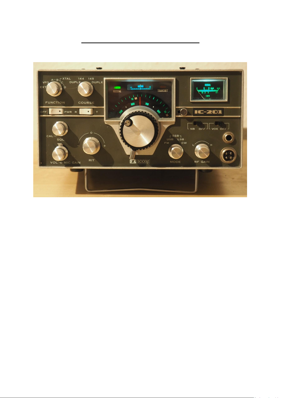
ICOM IC-201 Allmode Transceiver
Alignment Procedure
Please note: This procedure is reengineered by myself and may be not in accordance with
the original procedure from the manufacturer!
So I can´t accept any claims from anybody in case of injuries, problems, damages and losses.
Usage of this procedure is at own risk!
Of course you may ask me or give hints for improvement.
Page 1 (27)
Page 2

DL7MAJ, Oct 20th ,24th , 31st, Nov. 1st , 9th , 21st 2015, March 11th 2016
Required Equipment:
Counter, 150MHz
Multimeter, best with analog scale
RF-Generator 145MHz, level adjustable down to 0,05uV
IF-Generator 10,7MHz, FM
2nd RX for 2m or spectrum analyser
Scope, 50MHz with analog output for counter
Dummy load and Power Meter, 145MHz >15W
Resistor 25/20W (2 x 50 parallel)
Sweeper 10 … 15MHz
AF-Generator
Microphone and CW-Key
Optional: Spectrum analyser or Scope >250MHz for optimum of PA linearity
Page 2 (27)
Page 3
DL7MAJ, Oct 20th ,24th , 31st, Nov. 1st , 9th , 21st 2015, March 11th 2016
AF
1) Mode „USB“
2) No microphone connected; „MIC GAIN“ control to CCW
3) „VOX“ On
4) Adjust R50 that VOX doesn´t trip (search for the point where VOX trips without
Modulation and set R50 shortly before this point.
5) Check that for all modes (FM, USB, LSB, CW)VOX doesn’t trip without modulation
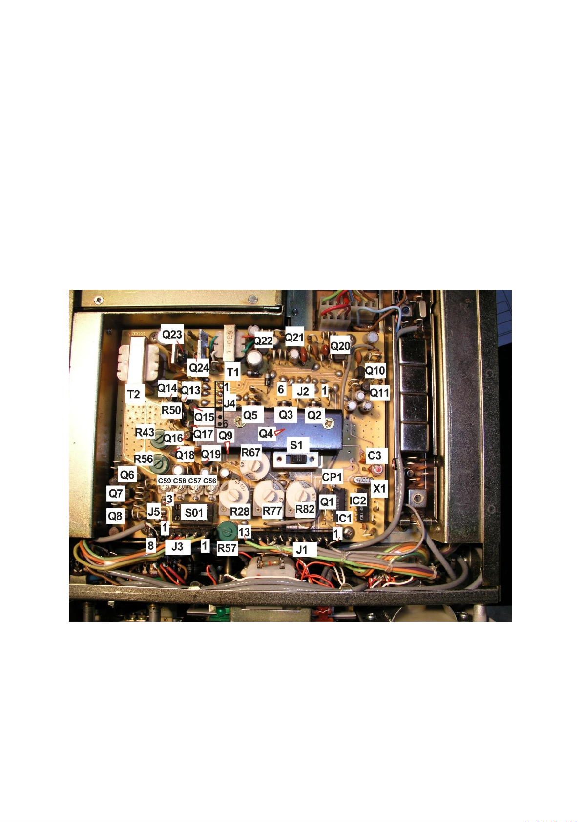
6) “CAL” switched on, connect counter to CP1. Best use analog scope with Y-output
7) Wait 1 minute
8) Adjust frequency to 2,500000 MHz
Page 3 (27)
Page 4

DL7MAJ, Oct 20th ,24th , 31st, Nov. 1st , 9th , 21st 2015, March 11th 2016
GIF
1) Receive “R”
2) Connect Counter (AC-coupled) to Emitter of Q14. Best use analog scope with Y-
output
3) Mode “USB” adjust C61 to 10,69850 MHZ (X1)
4) Mode “LSB” adjust C66 to 10,70150 MHz (X2)
5) There may be some interaction so repeat 3 and 4 if necessary
6) Mode “CW” frequency should remain at 10,70150 MHz (“RX”)
7) Transmit “T”
8) Mode “CW” frequency should move to nearly 10,70000 MHz (not more than +/-
500Hz)
9) Mode “FM” frequency should move to nearly 10,70000 MHz (not more than +/-
500Hz)
10) Note: At “FM” and receive “R” there is no output of BFO
11) Mode USB: Set R41 for just a little bit above S=0 (S-Meter just moves) on S-Meter
12) Tune in weak signal at 145,000MHz just enough to move S-Meter to S=5
13) Tune L1, L6, L8, L9, L10 for maximum
14) Tune in signal 50Mikrovolt 145,000MHz: Set R40 for S=9
15) Remove steps 11 and 14 if necessary
16) Mode “FM”
17) Adjust R1 on Main board near FM-Unit to S=9
18) Mode “USB”
19) Transmit “T”
20) Mode “USB” with PA operating (jumper P11/J11); adjust R66 for best carrier
suppression
21) Receive “R”
22) Connect AF signal (2kHz, 10mVpp) to MIC-Input
23) Set “MIC GAIN” to center position
24) Mode “USB”
25) Transmit “T”
26) Adjust output power with R69 to app.8 to 10W
27) Receive “R”
Page 4 (27)
Page 5

DL7MAJ, Oct 20th ,24th , 31st, Nov. 1st , 9th , 21st 2015, March 11th 2016
Page 5 (27)
Page 6
DL7MAJ, Oct 20th ,24th , 31st, Nov. 1st , 9th , 21st 2015, March 11th 2016
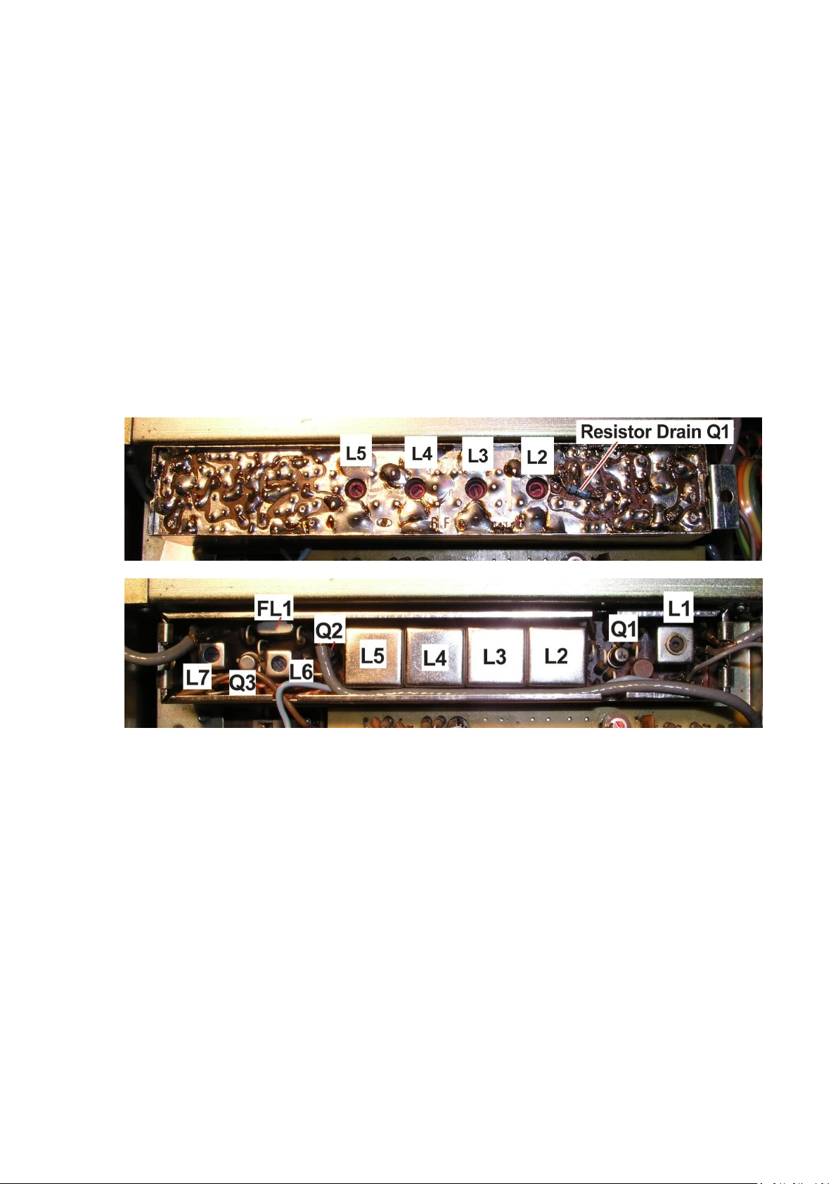
RF
1) Set “RF GAIN” to “H”
2) Weak signal at 145,000MHz just enough to move S-Meter to S=5
3) Tune L1, L6 and L7 for maximum AF or S-meter
4) Unmount RF-Module (one clamp at each end) and turn RF-module upside down
5) Tune L2 to L5 for maximum
6) Mount RF-Module
7) If a big increase of sensitivity has been achieved, then repeat adjustment of S-Meter
(Look for GIF, step 14)
Note:
The resistor at the drain of Q1 (18Ohm) is a modification for damping oscillations in case
of badly matches antennas!
Page 6 (27)
Page 7
DL7MAJ, Oct 20th ,24th , 31st, Nov. 1st , 9th , 21st 2015, March 11th 2016
Helical Filter
These filters (cores) are very sensitive, use appropriate tool only!
Adjust only if you feel that these filters are mismatched!
1) Weak signal at 145,000MHz just enough to move S-Meter to S=1 or 2
2) Connect sensitive AF-Voltmeter or scope parallel to speaker
3) Adjust both helical filters to maximum AF
4) Repeat at 144,000 and 145,999MHz
5) If you observe differences tune for maximum at 144,500MHz
Page 7 (27)
Page 8

DL7MAJ, Oct 20th ,24th , 31st, Nov. 1st , 9th , 21st 2015, March 11th 2016
Premix
1) “CAL” (Calibrator) switched off
2) Receive “R”, mode USB
3) Connect Counter (AC-coupled) to Collector of Q3. Best use analog scope with Y-
output
4) Connect DC-Voltmeter or Scope with 10:1 probe to common cathodes of D4 and D5.
5) “RIT” centered: Trim R8 for app. 0,3VDC
6) Set “Coarse” to 144 MHZ (simplex).
7) Measure frequency; should be app. 15,239 MHz.
8) Check: Tuning “RIT” should change frequency app. +/- 400 Hz – symmetrically to both
sides
9) If not readjust R8 and check again – back to 7)
10) “RIT” centered again.
11) Measure frequency; should be app. 15,239 MHz.
12) Switch to transmit “T”.
13) Adjust R9 for exactly same frequency as 10)
Note: Mode has to be “USB” not “FM”!
In FM there is a small difference in RIT adjustment compared with USB/LSB/CW!
14) Switch to “R”, “RIT” centered
15) “Coarse” 144 MHz: Adjust C6 to exactly 15,239375 MHz (X2)
16) “Coarse” 145 MHz: Adjust C5 to exactly 15,364375 MHz (X1)
17) “Coarse” 145 MHz DUPLX: Switch to “T” and adjust C70 to exactly 15,289375 MHz
(X3)
18) Check: 145 MHz in DUPLEX is on “RX” same as in 15 (15,364375 MHz)
19) Recheck 15, 16 and 17 in “R” and “T”
20) Connect AF signal (2kHz, 10mVpp) to MIC-Input
21) Connect Scope to Pin 9 of IC1 (MC3301P)
22) Mode “FM”, Transmit “T”
23) Adjust R52 for symmetrical clipping at Pin 9 of IC1;
adjust amplitude with “MIC GAIN” and R53 if necessary
24) DC-Level at Pin 9 of IC1 should be app. 4,5 to 5,0VDC without AF-Input
25) Check that AF at Pin 9 of IC1 is just clipped
26) Connect Jumper P1 to J3 and adjust FM-Deviation with R61 to 5.0kHz
27) Connect Jumper P1 to J4 and adjust FM-Deviation with R62 to 2.5KHz (for narrow
band FM)
28) Switch back to receive “R”
29) Note: Maximum deviation with constant AF input will be at 2.4kHz due to phase
modulation and frequency response of IC1 (R57/R59/R60/C59/C60)
Page 8 (27)
Page 9

DL7MAJ, Oct 20th ,24th , 31st, Nov. 1st , 9th , 21st 2015, March 11th 2016
Up to now, I´ve no procedure for aligning L3 to L14.
Page 9 (27)
Page 10

DL7MAJ, Oct 20th ,24th , 31st, Nov. 1st , 9th , 21st 2015, March 11th 2016
FM-IF
Alignment of FM-Unit can only be done outside the transceiver.
Use pins to connect supply (9V), Gnd, signals and meters acc. to the picture.
IMPORTANT:
An external trimmer R1 (10kOhm) has also to be connected, otherwise Q1 wouldn´t
operate.
1) Connect counter to TP2 (high impedance); frequency should be 10,245MHz +/-1kHz
Use analog scope, probe 10:1, with Y-output to connect the counter if available
2) Connect IF-Signal 10,700MHz, 1mV, unmodulated to pin 3 and 4(Gnd)
3) Connect DC-voltmeter to pin 10
4) Adjust L1 and L2 for max. negative AGC-voltage at pin 10; reduce amplitude of IF-
signalgenerator as far as possible to find the point of best sensitivity; try variation of
R1
5) FM-modulate IF-signal with sinus 1kHz and 5kHz deviation
6) Connect scope to pin 9, AF audio
7) Connect DC-voltmeter to pin 6, center meter
8) Adjust L3 and L4 for best demodulation (scope) and 0V at center meter
9) Reinstall FM-Unit into the transceiver
10) Mode “FM”, “RX”
11) Tune in signal 50Mikrovolt 145,000MHz: Set R1 (mainboard nearby the FM-Unit) for
S=9
Page 10 (27)
Page 11

DL7MAJ, Oct 20th ,24th , 31st, Nov. 1st , 9th , 21st 2015, March 11th 2016
Page 11 (27)
Page 12

DL7MAJ, Oct 20th ,24th , 31st, Nov. 1st , 9th , 21st 2015, March 11th 2016
T-MIX
1) Alignment requires an sweeper
2) Coarse “145MHz” *)
3) Connect sweeper to the external VFO input: J2 pins 8 (Gnd) and 9
4) Set sweep to 10,000 to 13,000MHz, app. 0dBm (700mVpp) *)
5) Mode “FM”
6) 50 Demodulator (10W) and viewer (scope) at Antenna output
7) Sweeper output to zero
8) “TX”
9) Set sweeper output to app. 1W at antenna output
10) Tune L1 to maximum
11) Tune L3 to L9 to maximum and flat response in the range of 10,385 to 12,385MHz *)
12) Also tune L2 and L3 of the Buffer Amplifier for flat response (see Buffer Amplifier)
13) Reduce sweeper output when 1W at antenna output is exceeded
14) Tune C32, C35, C43 and C44 to maximum and flat response in the range of 10,385 to
12,385MHz
15) Go back to 10 until result is satisfying: Flat response (+/- 3dB in the range of 10,385
to 12,385MHz
*) With “Coarse” 145MHz and sweeper from 10,385 to 13,385MHz the output is 144 to
146MHz
Page 12 (27)
Page 13

DL7MAJ, Oct 20th ,24th , 31st, Nov. 1st , 9th , 21st 2015, March 11th 2016
Buffer Amplifier
This amplifier is located on the bottom of the chassis. It´s not necessary to remove the
FM-Unit, adjustment of L2 and L3 can be made with the FM-Unit in place through the
two holes in the clamp.
Alignment: See T-MIX
Page 13 (27)
Page 14

DL7MAJ, Oct 20th ,24th , 31st, Nov. 1st , 9th , 21st 2015, March 11th 2016
Final/PA
1) “Coarse” to 145MHz, VFO to 000 (equals 145,000MHz)
2) Remove heatsink from rear of PA-unit (from now on observe it´s temperature)
3) Connect Dummyload 50W and Powermeter to antenna output
4) Remove jumper P11 from J11
5) “CW”, unkeyed
6) Connect A-meter between pin 2 & 3 of J11 (measures current of Q1)
7) “TX”
8) Adjust R3 for app. 30 to 40mA
9) “RX”
10) Connect A-meter between pin 1 & 4 of J11 (measures current of Q2)
11) “TX”
12) Adjust R8 for app. 80 to 90mA
13) “RX”
14) Mode “FM” and “TX”
15) Adjust C11, C12, C22, C23 for maximum output; should be 10W
16) Maybe TX-limiter R13 limits the output; then adjust R13 for 10W and go back to 15)
17) Adjust R12 for SWR=0
18) Connect resistor 25/20W to antenna output (2 x 50 parallel)
19) Adjust R17 for reducing TX-output: SWR protection at SWR = 2
Reinstall the heatsink:
Clean it from old thermal compound and use new one.
Page 14 (27)
Page 15

DL7MAJ, Oct 20th ,24th , 31st, Nov. 1st , 9th , 21st 2015, March 11th 2016
Page 15 (27)
Page 16

DL7MAJ, Oct 20th ,24th , 31st, Nov. 1st , 9th , 21st 2015, March 11th 2016
Remove plug, connect A-meter
Page 16 (27)
Page 17

DL7MAJ, Oct 20th ,24th , 31st, Nov. 1st , 9th , 21st 2015, March 11th 2016
VFO
1) Let the VFO warm up for app. 10 Minutes
2) Adjust tuning range of VFO with L1 to exactly 1000kHz (use internal calibrator as
reference)
3) If you adjust L1, a realignment of the mechanical scale is necessary.
4) Repeat 2) and 3) if necessary
Be very careful! Use plastic trimmers only – otherwise destruction of L1 will result!
(And you are a fool for the rest of you life….)
Page 17 (27)
Page 18

DL7MAJ, Oct 20th ,24th , 31st, Nov. 1st , 9th , 21st 2015, March 11th 2016
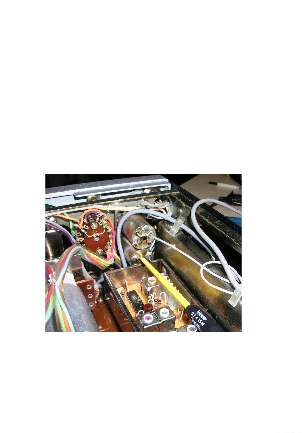
(De-) Installation of the VFO, Sequence
Page 18 (27)
Page 19

DL7MAJ, Oct 20th ,24th , 31st, Nov. 1st , 9th , 21st 2015, March 11th 2016
Page 19 (27)
Page 20

DL7MAJ, Oct 20th ,24th , 31st, Nov. 1st , 9th , 21st 2015, March 11th 2016
Page 20 (27)
Page 21

DL7MAJ, Oct 20th ,24th , 31st, Nov. 1st , 9th , 21st 2015, March 11th 2016
Page 21 (27)
Page 22

DL7MAJ, Oct 20th ,24th , 31st, Nov. 1st , 9th , 21st 2015, March 11th 2016
Page 22 (27)
Page 23

DL7MAJ, Oct 20th ,24th , 31st, Nov. 1st , 9th , 21st 2015, March 11th 2016
Page 23 (27)
Page 24

DL7MAJ, Oct 20th ,24th , 31st, Nov. 1st , 9th , 21st 2015, March 11th 2016
Following pictures show the VFO drive and its (dis-)assembly.
Page 24 (27)
Page 25

DL7MAJ, Oct 20th ,24th , 31st, Nov. 1st , 9th , 21st 2015, March 11th 2016
Page 25 (27)
Page 26

DL7MAJ, Oct 20th ,24th , 31st, Nov. 1st , 9th , 21st 2015, March 11th 2016
Page 26 (27)
Page 27

DL7MAJ, Oct 20th ,24th , 31st, Nov. 1st , 9th , 21st 2015, March 11th 2016
If you want to contact the author:
Stefan Steger, DL7MAJ, eMail: dl7maj@darc.de
Homepage: www.dl7maj.de
Page 27 (27)
 Loading...