

Page 1

PROGRAMMING
MANUAL
CLONING SOFTWARE
CS-F3G
Page 2

i
TABLE OF CONTENTS
FOREWORD
This manual explains in detail how to program each of
the functions in the IC-F3GT/GS and IC-F4GT/GS VHF
AND UHF TRANSCEIVERS
with the CS-F3G CLONING SOFT-
WARE. The CS-F3G can be set up to meet any number
of requirements of your customers, such as system
conditions, channels, frequencies, tones, etc.
IMPORTANT
Before using the program, make a backup copy of the
original disk. Operate the program using the backup
and keep the original in a safe place.
FOREWORD . . . . . . . . . . . . . . . . . . . . . . . . . . . . . . i
IMPORTANT . . . . . . . . . . . . . . . . . . . . . . . . . . . . . . i
TABLE OF CONTENTS . . . . . . . . . . . . . . . . . . . . . i
1 PREPARATION . . . . . . . . . . . . . . . . . . . . . . 1
2 SCREEN DESCRIPTION . . . . . . . . . . . . . 2–5
2-1 MAIN SCREEN DESCRIPTION . . . . . . . . . 2–3
2-2 TREE VIEW SCREEN DESCRIPTION . . . . 4–5
3 COMMON SETTING . . . . . . . . . . . . . . . 6–18
3-1 KEY & DISPLAY ASSIGN . . . . . . . . . . . . 6–12
3-2 COMMON 1 . . . . . . . . . . . . . . . . . . . . . . 13–14
3-3 COMMON 2 . . . . . . . . . . . . . . . . . . . . . . 15–16
3-4 EXPERT . . . . . . . . . . . . . . . . . . . . . . . . 17–18
4 MEMORY CHANNEL— LMR . . . . . . . . 19–23
5 MEMORY CHANNEL— PMR . . . . . . . . 24–32
6 DTMF AUTODIAL . . . . . . . . . . . . . . . . 33–34
6-1 DTMF AUTODIAL . . . . . . . . . . . . . . . . . . . . 33
6-2 DTMF SETTING . . . . . . . . . . . . . . . . . . . . . 34
7 CONTINUOUS TONE . . . . . . . . . . . . . . . . 35
8 SCAN LIST . . . . . . . . . . . . . . . . . . . . . 36–37
8-1 SCAN LIST . . . . . . . . . . . . . . . . . . . . . . . . . 36
8-2 SCAN SETTING . . . . . . . . . . . . . . . . . . . . . 37
9 2TONE . . . . . . . . . . . . . . . . . . . . . . . . . 38–40
9-1 RX CODE CHANNEL . . . . . . . . . . . . . . . 38–39
9-2 TX CODE . . . . . . . . . . . . . . . . . . . . . . . . . . 40
9-3 2TONE SETTING . . . . . . . . . . . . . . . . . . . . 40
10 5TONE . . . . . . . . . . . . . . . . . . . . . . . . 41–49
10-1 RX CODE CHANNEL . . . . . . . . . . . . . . 41–42
10-2 TX CODE CHANNEL . . . . . . . . . . . . . . 43–44
10-3 FORMAT . . . . . . . . . . . . . . . . . . . . . . . . . . 45
10-4 USER TONE . . . . . . . . . . . . . . . . . . . . . . . 46
10-5 5TONE SETTING . . . . . . . . . . . . . . . . 47–49
11 PROGRAMMING for SmarTrunk II operation
. . . . . . . . . . . . . . . . . . . . . . . . . . . . . . . 50–52
11-1 STARTING THE PROGRAM . . . . . . . . . . . 50
11-2 PROGRAMMING RECOMMENDATION . . . 50
11-3 Speed Dial . . . . . . . . . . . . . . . . . . . . . . . . . 51
11-4 Configuration . . . . . . . . . . . . . . . . . . . . . . . 52
12 PROGRAMMING for LTR®TRUNKING
operation . . . . . . . . . . . . . . . . . . . . . . 53–54
12-1 STARTING THE PROGRAM . . . . . . . . . . . 53
12-2 Global . . . . . . . . . . . . . . . . . . . . . . . . . . . . 53
12-3 System 1, System 2 . . . . . . . . . . . . . . . . . . 54
13 DATA CLONING BETWEEN
TRANSCEIVERS . . . . . . . . . . . . . . . . . . . 55
14 PROGRAMMING EXAMPLE . . . . . . . 56–83
14-1 EXAMPLE 1 . . . . . . . . . . . . . . . . . . . . . 56–59
14-2 EXAMPLE 2 . . . . . . . . . . . . . . . . . . . . . 60–61
14-3 EXAMPLE 3 . . . . . . . . . . . . . . . . . . . . . 62–65
14-4 EXAMPLE 4 . . . . . . . . . . . . . . . . . . . . . 66–69
14-5 EXAMPLE 5 . . . . . . . . . . . . . . . . . . . . . 70–73
14-6 EXAMPLE 6 . . . . . . . . . . . . . . . . . . . . . 74–78
14-7 EXAMPLE 7 . . . . . . . . . . . . . . . . . . . . . 79–83
15 OPTIONAL UNIT INSTALLATION . . . 84–85
■ GENERAL . . . . . . . . . . . . . . . . . . . . . . . . . . . 84
15-1 INSTALLATION . . . . . . . . . . . . . . . . . . . . . 84
15-2 HARDWARE SETUP . . . . . . . . . . . . . . . . . 85
16 PAGER/CODE SQUELCH . . . . . . . . . 86–93
16-1 PAGER FUNCTION . . . . . . . . . . . . . . . 86–89
16-2 CODE SQUELCH FUNCTION . . . . . . . 90–93
17 SPECIAL FUNCTION . . . . . . . . . . . . . . . 94
17-1 CPU REVISION INDICATION . . . . . . . . . . 94
17-2 USER SET MODE . . . . . . . . . . . . . . . . . . . 94
18 INDEX . . . . . . . . . . . . . . . . . . . . . . . . 95–97
Page 3
■ EQUIPMENT REQUIRED
To use the program, the following hardware and software is required:
• IBM PC/AT or PS/2 compatible computer with an RS-232C serial port
• Microsoft®Windows®95 or Windows®98
• Intel Pentium 100 MHz processor or faster
• At least 16 MB RAM
• At least 800×600 pixel display
• OPC-478 CLONING CABLE
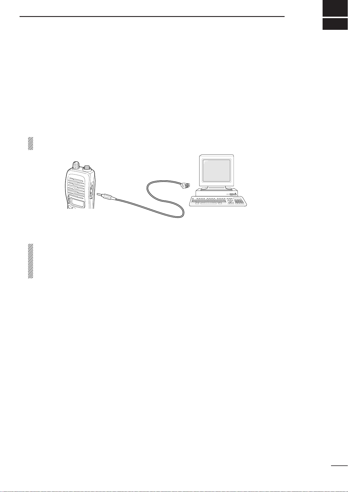
■ CONNECTION
Connect each item as in the following diagram.
CAUTION: Do not connect an antenna to the transceiver during cloning operation. Received signals
may cause cloning errors.
■ SOFTWARE INSTALLATION
NOTE:
1. Before using the program, make a backup copy of the original disk. After making a backup copy , keep
the original disk in a safe place.
2. Depending on your Windows®system files, the PC may require rebooting. In this case, repeat the
installation from the beginning.
◆ Installation
q Boot up Windows®. (Quit all applications when Windows®is running.)
w Insert the CS-F3G backup disk into the appropriate floppy disk drive.
e Select ‘Run’from the [Start] menu.
r Type the setup program name with full path name, then press the [Enter] key.
e.g.; A:\setup [Enter]
t Follow the prompts.
y Program group ‘CS-F3G’appears in the ‘Programs’ folder of the start menu.
PREPARATION
1
1
DB9 female plug
(incl. level converter circuit)
to an RS-232C port
Personal
computer
OPC-478
to the speaker
connector
IBM PC/AT and PS/2 are trademarks of International Business Machines. Microsoft and Windows are registered trademarks of
Microsoft Corporation.
Page 4
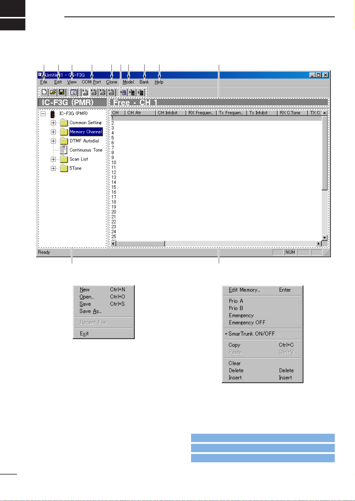
2-1 MAIN SCREEN DESCRIPTION
q FILE MENU— [File]
Used for making new file, opening available saved file,
saving memory channel contents or quitting the program, etc.. Up to 4 recently used files are indicated in
the sub menu for simple, quick file selection.
w EDIT MENU— [Edit]
Edit the selected memory contents.
• Select the proper model type, item and channel number before editing items. (see u, !1 and !2;p.3)
*The above sub menu shows in the case that a memory
channel is selected. When an other item is selected, a different sub menu is appears.
2
SCREEN DESCRIPTION
2
Go to !1 TREE VIEW SCREEN
Go to !2 MEMORY CHANNEL SCREEN
Go to u MODEL MENU— [Model]
qwe r tyu io !0
!1 !2
Page 5
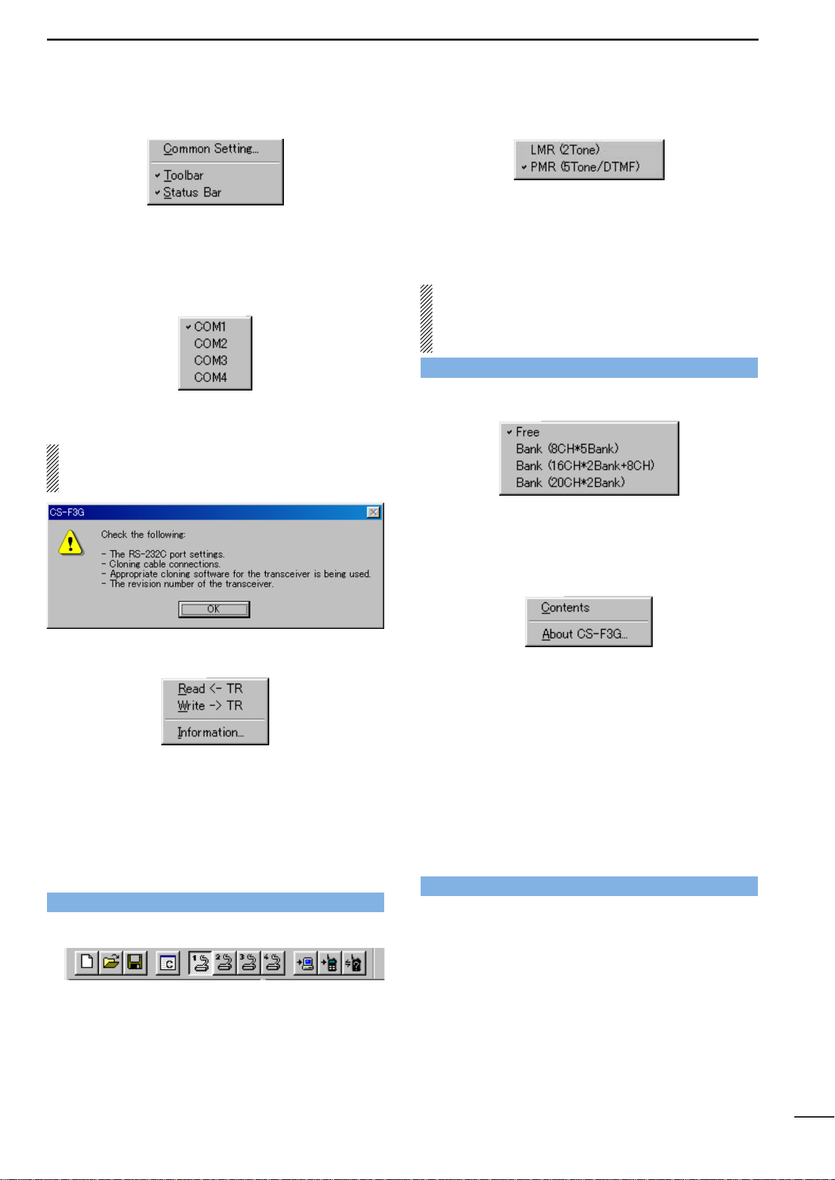
e VIEW MENU— [View]
• The independent Common Setting Screen is selectable. (pgs. 6–18)
• Turn the tool bar or status bar ON/OFF.
r COM PORT MENU— [COM Port]
Push to display the COM port setting sub menu.
• Set the COM port (RS-232C port) number properly.
NOTE: ‘Check the following’ dialog box as follows,
appears when the RS-232C serial port is not set correctly .
t CLONE MENU— [Clone]
Starts to read the programmed data from the connected transceiver, programs setup data to the connected
transceiver, or displays detailed information screen to
check Model type, CPU’s revision, clone comment and
optional unit installation condition of the connected
transceiver.
The clone comment is programmed in Clone
Comment— (1), (2) in
3-2 COMMON 1
(p. 14)
y TOOL BAR
Short cut keys appear on the tool bar when the tool bar
is checked (“✔” mark appears) in the [View] menu as
above.
Short cut keys for New (Ctrl+N), Open (Ctrl+O), Save
(Ctrl+S) as in [File], Common Setting as in [View], COM1–4
selection as in [COM Port] and Read <– TR, Write –> TR,
Information as in [Clone] menu, are available.
u MODEL MENU— [Model]
Select model type from LMR (2-tone) or PMR (5tone/DTMF).
-“✔” mark appears for the selected model.
The Tree View Screen will be changed when switched
between LMR and PMR. See page 5 for details.
IMPORTANT! : The model type must be selected
at first, otherwise the edited contents will be lost.
Select PMR (5Tone/DTMF) to enable the DTMF
decode operation when UT-108 is installed.
i BANK MENU— [Bank]
Push to select bank type. Free, 8CH*5Bank,
16CH*2Bank + 8CH, 20CH*2Bank are available.
-“✔” mark appears for the selected bank type.
o HELP MENU— [Help]
Push to display help contents and cloning software
revision information.
!0 EDITABLE CHANNEL INDICATION
Displays the prompt editable item name and channel
number.
!1 TREE VIEW SCREEN (p. 4)
Double click the folder icon or click the “|+” beside the
folder which you want to edit. Then double click the
desired item name to display the item on the ‘Memory
channel screen’.
!2 MEMORY CHANNEL SCREEN
Display the Memory Channel or editable item information. Double click, right click on the desired channel
number, or press [Enter] key after desired channel
selection to open the independent ‘Edit’ screen.
3
SCREEN DESCRIPTIONS
2
Go to 2-2 TREE VIEW SCREEN DESCRIPTION
Go to 2-2 TREE VIEW SCREEN DESCRIPTION
Go to Clone Comment— (1), (2)
Page 6
4
SCREEN DESCRIPTIONS
2
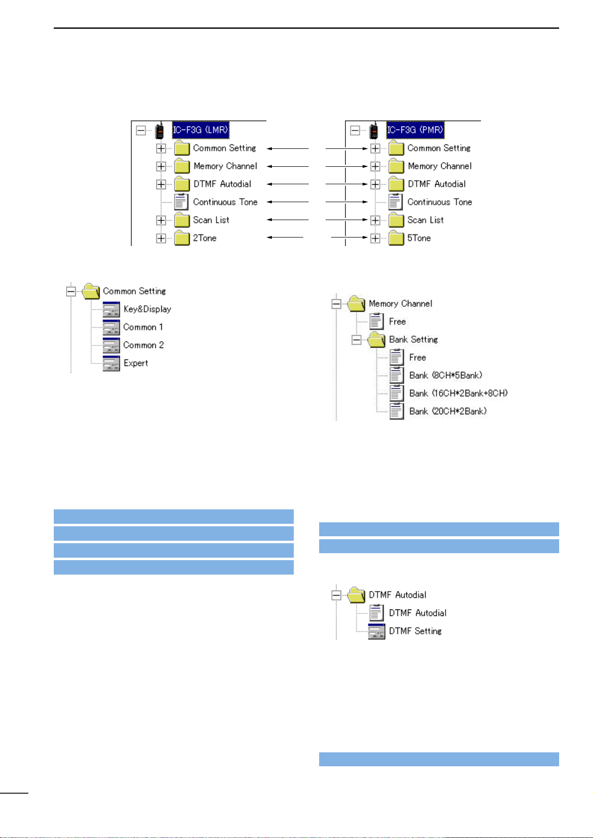
2-2 TREE VIEW SCREEN DESCRIPTION
q Common setting (pgs. 6–18)
Set programmable key, function display assign, and
several commonly used timers, etc., are programmable in 4 independent sheets as follow.
Key & Display Assign
(pgs. 6–12)
Common 1
(pgs. 13–14)
Common 2
(pgs. 15–16)
Expert
(pgs. 17–18)
By double clicking an item in the Common Setting folder, the desired sheet in the independent Common
Setting Screen appears.
w Memory Channel
(LMR: pgs. 19–23/PMR: pgs. 24–32)
Set channel attribute, operating frequency, CTCSS
encoder/decoder frequency, transmit output power,
voice scrambling code, etc..
By double clicking a bank type item in the Bank Setting
folder, the desired bank condition is indicated below
the Memory Channel folder and editable channel number, in a bank in the Memory Channel Screen.
e DTMF Autodial (pgs. 33–34)
Program DTMF code for the DTMF auto dialling function and timers for each digit, 1st digit, [✽] and [#]
code.
By double clicking the DTMF Autodial item, the
editable DTMF channels appear in the Memory
Channel Screen, and the independent DTMF Setting
Screen appears when the DTMF Setting item is double
clicked.
q
w
e
r
t
yu
• LMR Tree View • PMR Tree View
Go to 3-1 KEY & DISPLAY ASSIGN
Go to 4 MEMORY CHANNEL— LMR
Go to 5 MEMORY CHANNEL— PMR
Go to 6 DTMF AUTODIAL
Go to 3-2 COMMON 1
Go to 3-3 COMMON 2
Go to 3-4 EXPERT
Page 7
r Continuous Tone (p. 35)
Set continuous tone frequency. The programmed continuous tone is used for encoder and/or decoder.
By double clicking the Continuous Tone item, the
editable continuous tone channels appear in the
Memory Channel Screen.
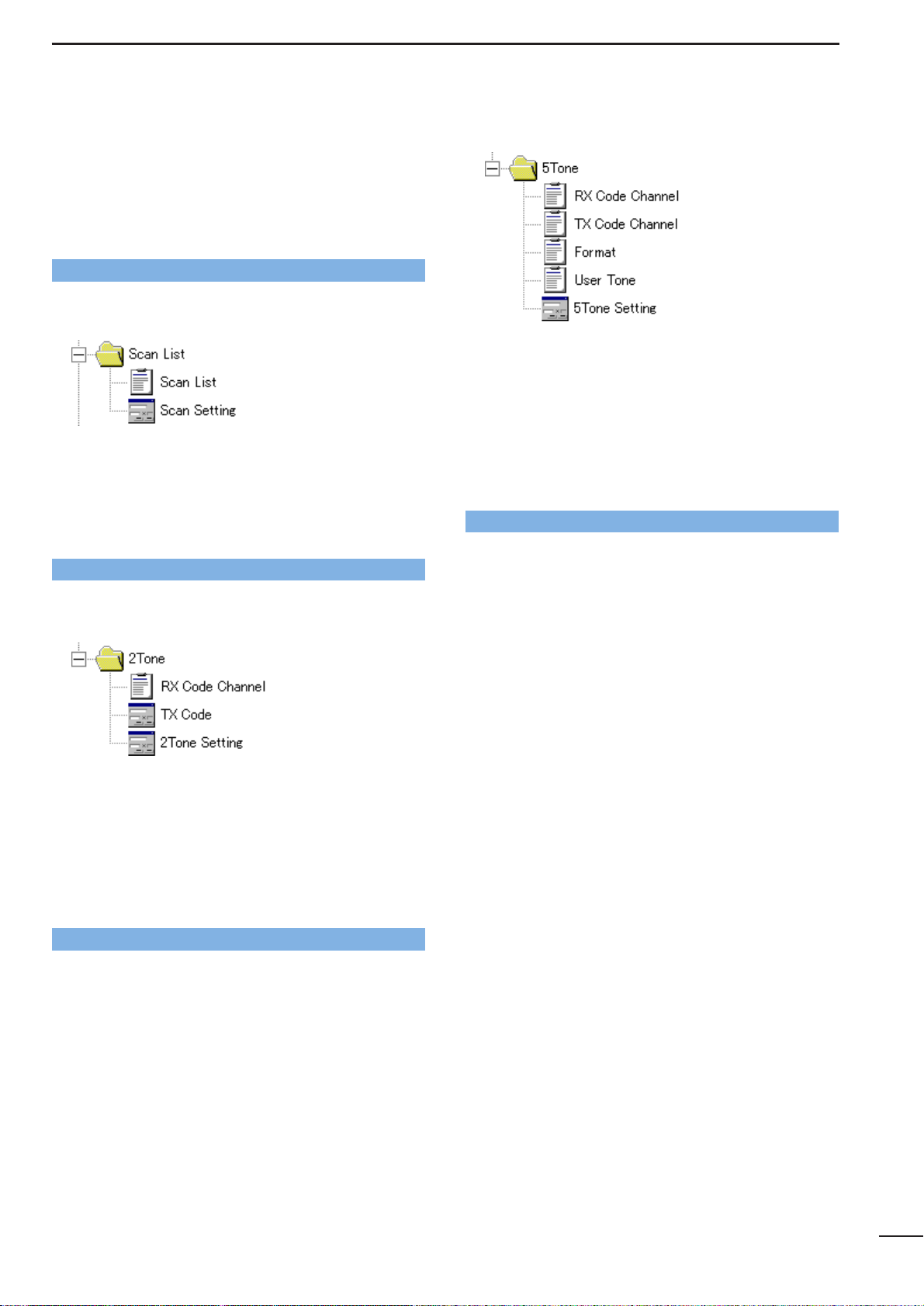
t Scan List (pgs. 36–37)
Set scan mode, text for each scan group, power save
function scan stop/resume timers, etc..
By double clicking the Scan List item, the editable scan
group channels appear in the Memory Channel
Screen, and the independent Scan Setting Screen
appears when the Scan Setting item is double clicked.
y 2Tone (LMR only; pgs. 38–40)
Set RX/TX code, text, beep, bell, stun, group call, ANS
functions, etc..
By double clicking the RX Code Channel item, the
editable RX code channels appear in the Memory
Channel Screen, and the independent TX Code
Channel or 2Tone Setting Screen appears when the
TX Code Channel or 2Tone Setting item is double
clicked, respectively.
u 5Tone (PMR only; pgs. 41–49)
Set RX/TX code, text, 5-tone format, beep, bell, stun,
group call, answer back functions, etc..
By double clicking the RX/TX Code Channel, Format
or User Tone item, the editable RX/TX code channels,
5-tone format or user tone appear in the Memory
Channel Screen, and the independent 5Tone Setting
Screen appears when the 5Tone Setting item is double
clicked.
5
SCREEN DESCRIPTIONS
2
Go to 7 CONTINUOUS TONE
Go to 8 SCAN LIST
Go to 9 2TONE
Go to 10 5TONE
Page 8
COMMON SETTING
3
6
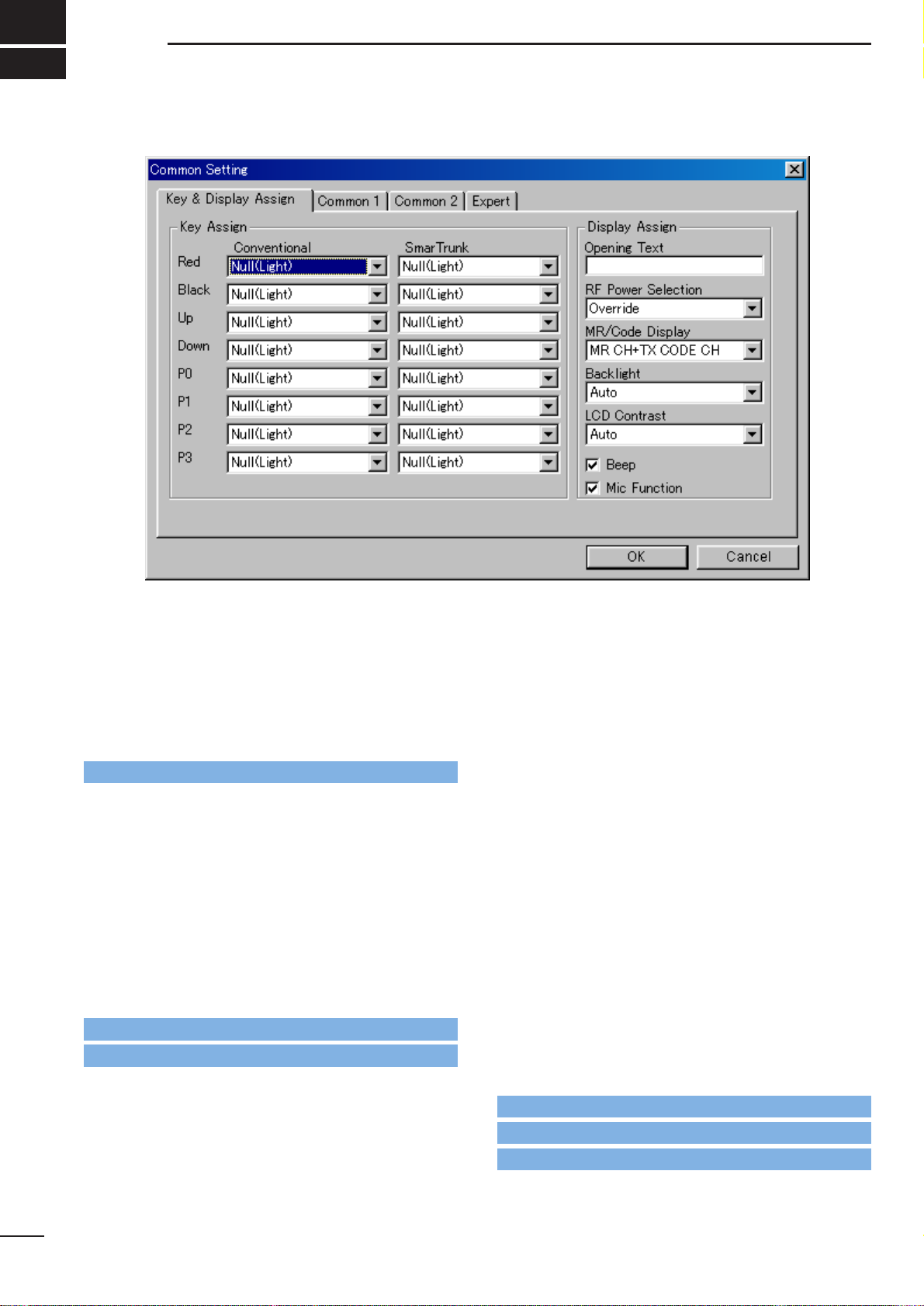
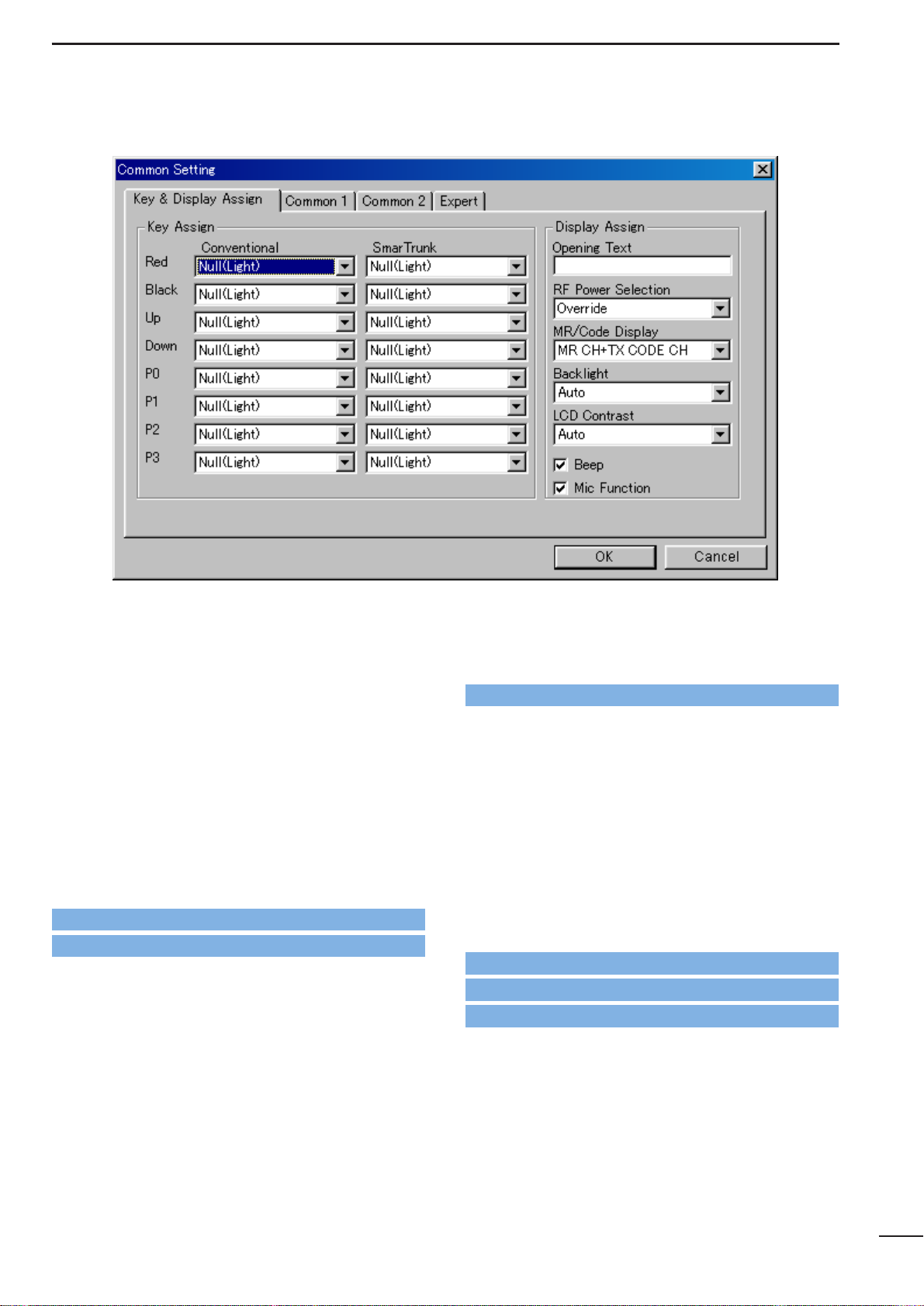
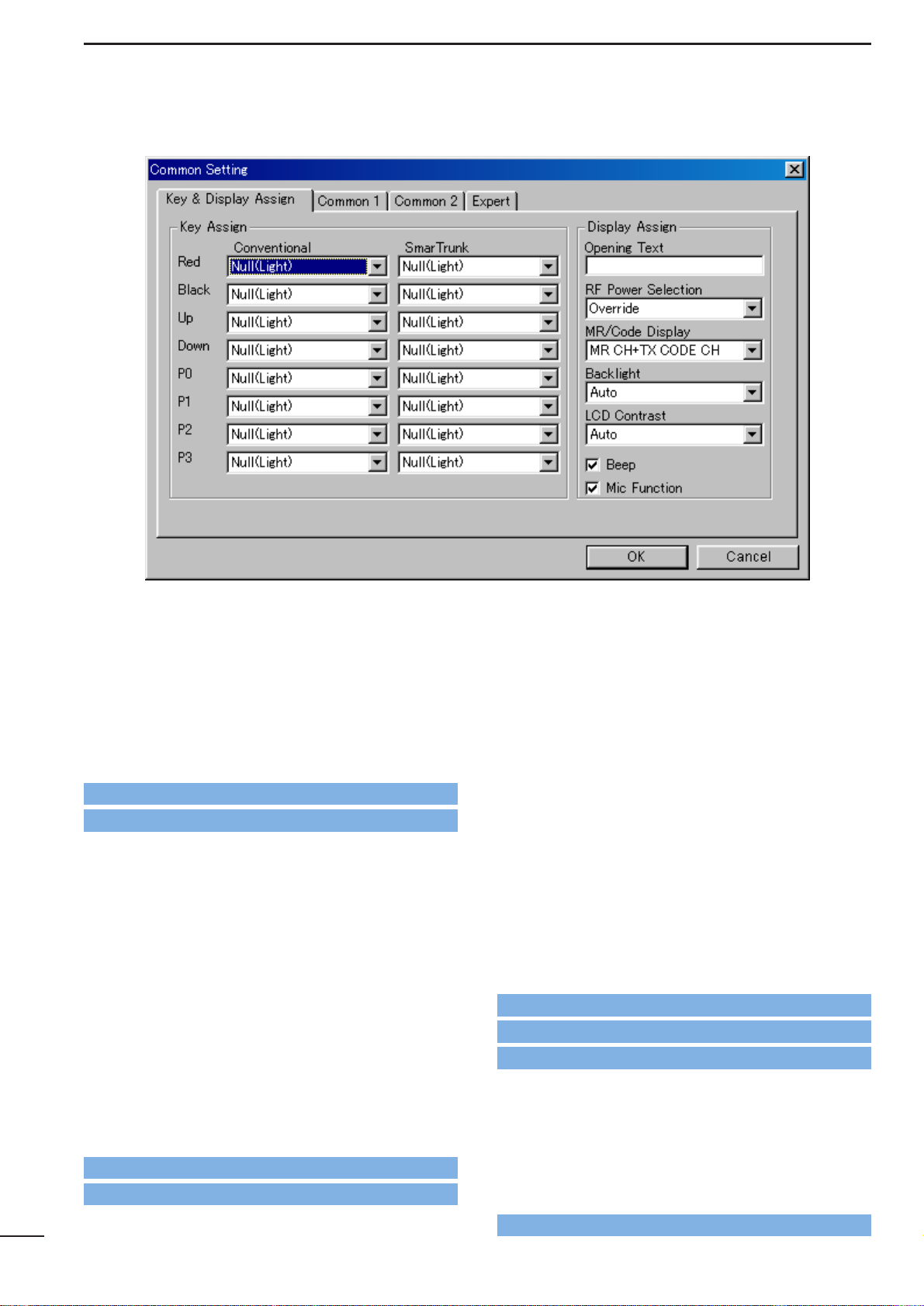
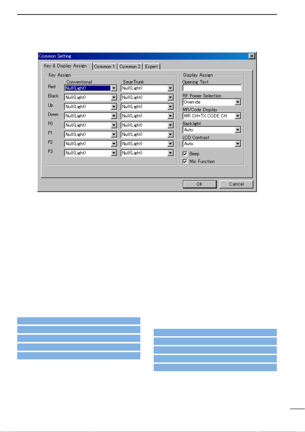
■ Key Assign—Red, Black, Up (▲), Down (▼) , P0,
P1, P2, P3
Assign a function for each programmable switch and
operating mode (Conventional and SmarTrunk).
Assignable functions and actions are as follows.
Null(Light)
: No function is assigned. However, lights
LCD backlight for 5 sec. when ‘Auto’ is
selected in Backlight (p. 12) in this screen.
CH Up, CH Down:
Changes memory channel. Memory channel is selectable when assigning this function, besides the original [CH Up (▲)] or
[CH Down (▼)] switches.
Bank Up : Changes memory channel bank for when
either 8CH*5Bank, 16CH*2Bank + 8CH,
20CH*2Bank is selected in the BANK menu
(p. 3) or, double click the desired bank icon
in the Bank Setting folder in the Tree View
Screen (p. 4).
Scan A, Scan B:
When the power ON scan function is turned OFF;
Push to start and cancel scanning operation. In case of transmission during scan,
cancels scanning when in Scan A, and
pauses scanning, then resumes scanning
after passing the time period specified in
Auto Reset in
4/5 MEMORY CHANNEL
(LMR; p. 22/PMR; p. 31) when Scan B is
selected.
The scanning list (scanning channel group)
can be selected via [CH Up] or [CH Down]
switches, after entering the scan list selection mode by pushing this switch for 1 sec..
When the power ON scan function is turned ON;
Push to pause scanning when in Scan A,
and push to cancel scanning when Scan B
is selected. In case of transmission during
scan, pauses scanning, then resumes
scanning after passing the time period
specified in the Auto Reset in
4/5 MEMO-
RY CHANNEL
(LMR; p. 22/PMR; p. 31)
when in Scan A. Cancels scanning when
Scan B is selected.
The scanning list (scanning channel group)
can be selected via [CH Up] or [CH Down]
switches, after entering the scan list selection mode by pushing this switch for 1 sec..
The power ON scan function is specified in Power
ON Scan in
8-2 SCAN SETTING
(p. 37).
NOTE: Scan A and Scan B cannot be assigned at
the same time because the transceiver cannot have two different scans.
3-1 KEY & DISPLAY ASSIGN
Go to Backlight
Go to u BANK MENU
Go to w Memory Channel
Go to Auto Reset— LMR
Go to Auto Reset— PMR
Go to PWR ON Scan
Page 9
7
COMMON SETTING
3
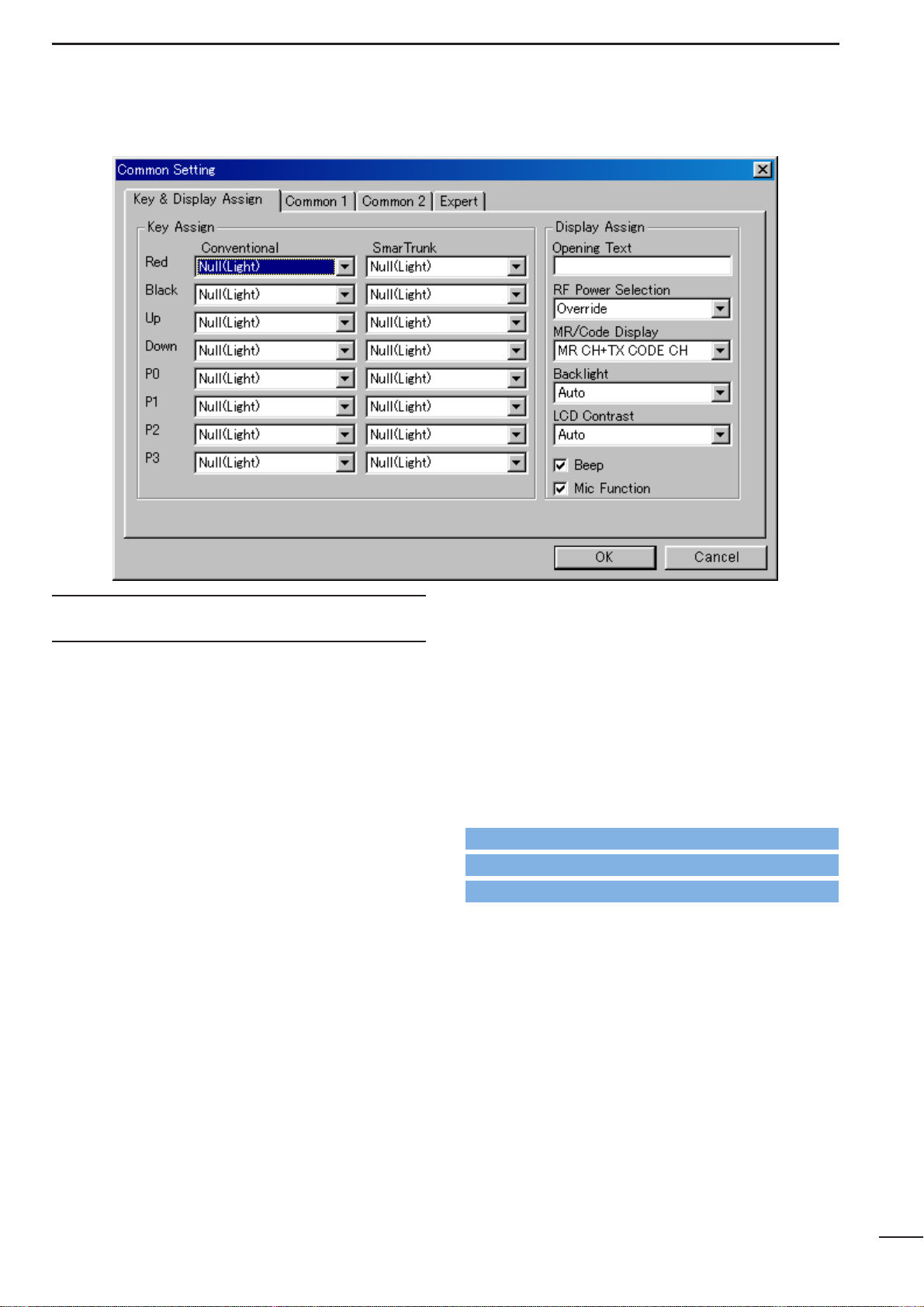
3-1 KEY & DISPLAY ASSIGN— continued
Scan Add/Del(Tag):
Push to add or delete the channel to/from
the selected scanning list
Prio A, Prio B:
Selects the priority channel A or B programmed in CH Atr in
4/5 MEMORY
CHANNEL
respectively (LMR; p. 19/PMR:
p. 24) by pushing this switch.
Prio A (Rewrite):
Selects the priority channel A programmed
in CH Atr in
4/5 MEMORY CHANNEL
(LMR; p. 19/PMR: p. 24) by pushing this
switch. Also the operating channel is reassigned for priority channel A by pushing
this switch for 1 sec..
MR-CH 1–4:
Immediately selects memory channel 1–4,
respectively.
Moni/Moni(Audi):
For LMR model action— Moni
Push to mute and release the CTCSS
(DTCS) or 2-tone squelch mute. Open any
squelches/deactivate any mutes while
pushing this switch.
For PMR model action— Moni (Audi)
Activates a monitor function specified in
Switch Action— Moni in
5 MEMORY
CHANNEL— PMR
(p. 27).
Lock : Switches keyboard lock function ON and
OFF.
Beep : Switches key touch beep ON and OFF.
High/Low: Switches transmit output power level from
the independent settings of each channel.
It is impossible to select “High” when “Low”
is selected for the initial setting in RF PWR
in
4/5 MEMORY CHANNEL
(LMR;
p. 22/PMR; p. 29) as well as when “MR CH
Individual” is selected in the RF Power
Selection (p. 11) in this sheet.
Go to CH Atr— LMR
Go to CH Atr— PMR
Go to Switch Action— Moni
Go to RF PWR— LMR
Go to RF PWR— PMR
Go to RF Power Selection
Page 10
3-1 KEY & DISPLAYASSIGN— continued
C. Tone CH Ent:
Selects continuous tone channel via [CH
Up] or [CH Down] switches to change the
tone frequency/code setting after pushing
this switch for temporary operation.
The [CH Up] or [CH Down] switches are
assigned in this screen (p. 6) and the continuous tone channel is programmed in
7
CONTINUOUS TONE
(p. 35),
Talk Around:
Toggles the talk around function ON and
OFF.
This function allows temporary simplex
operation on the duplex/repeater channel.
DTMF Autodial:
Push this switch for entering the DTMF
autodial mode and then select the stored
DTMF code via [CH Up] or [CH Down]
switches.
Transmits the selected DTMF code by
pushing this switch for 1 sec..
The DTMF code for auto dialling is programmed in
6-1 DTMF AUTODIAL
(p. 33),
and
the [CH Up] or [CH Down] switches are
assigned in this screen (p. 6).
Re-Dial : Transmits the last-transmitted DTMF code
again. Acts for both manual and autodial.
Re-Dial will be cleared when the transceiver is turned OFF once.
Call : Transmits the 2-tone (LMR) or 5-tone or
DTMF code (PMR) in the selected channel.
2-tone is programmed in Option— 2Tone in
4 MEMORY CHANNEL— LMR
(p. 20)
5-tone is programmed in 5T one Signaling—
RPT, STN, ID in
5 MEMORY CHANNEL—
PMR
(p. 29)
For PMR model action only
In case this switch is pushed, and the 5tone setting is an “OFF” channel, it transmits the previously transmitted 5-tone code,
when the automatic clear channel searching function is activated, specified in the
Auto CH Call in
8-2 SCAN SETTING
(p. 37).
Call A (Code 30), Call B (Code 29)—
PMR only
:
Transmits the 5-tone code programmed in
the channel 30 (Call A) or 29 (Call B) in 10-2
TX CODE (p. 43) as the station code when
[Call A] or [Call B] switch is pushed, respectively .
8
COMMON SETTING
3
Go to CH Up, CH Down
Go to 7 CONTINUOUS TONE
Go to 6-1 DTMF Autodial
Go to CH Up, CH Down
Go to Auto CH Call
Go to 10-2 TX Code
Go to Option— 2Tone
Go to 5Tone Signaling— RPT, STN, ID
Page 11
9
COMMON SETTING
3
3-1 KEY & DISPLAYASSIGN— continued
Emergency Repeat, Emergency Single:
Immediately selects emergency channel
and automatically sends a repeated emergency signal at specified time intervals or
an emergency signal once, by pushing this
switch for the specified time period, programmed in Emergency— SW ON Timer
in
3-4 EXPERT
(p. 17). Also, cancels the
emergency call by pushing this switch for
the specified time period, programmed in
Emergency— SW OFF Timer in
3-4
EXPERT
(p. 17), before an emergency signal is transmitted.
The emergency channel is specified in CH
Atr in
4/5 MEMORY CHANNEL
(LMR;
p. 19/PMR; p. 24) and the time intervals are
specified in the Emergency—
Start/Repeat in
3-4 EXPERT
(p. 18).
TX Code—
PMR only
:
Selects a TX code channel, instead of the
specified 5-tone code channel programmed
in 5Tone signaling— STN in
5 MEMORY
CHANNEL— PMR
(p. 29), via [CH Up] or
[CH Down] switches after
pushing this
switch for temporary operation.
The station code can also be manually
entered as at above right.
To enter 5-tone code—
IC-F3GT/F4GT : Enter the station code using [0]–[9]
and [✽] switches after pushing this
switch for 1 sec..
IC-F3GS/F4GS: Select the code number via
[CH Up] or [CH Down] switches
after pushing this switch for 1 sec.,
then push this switch to set the next
code number. After all digits are
selected, push this switch for 1 sec.
to complete the number.
Selectable 5-tone channels, acceptable
input digits and updates can be specified in
Sel (p. 44), Input Digit (p. 43) and Update
(p. 43) in
10-2 TX CODE CHANNEL
.
The [CH Up] and [CH Down] switches are
assigned in this screen (p. 6).
Go to Emergency— SW ON Timer
Go to Emergency— SW OFF Timer
Go to 5Tone signaling— STN
Go to Sel
Go to Input Digit
Go to Update
Go to CH Atr— LMR
Go to CH Atr— PMR
Go to Emergency— Start/Repeat
Go to CH Up, CH Down
Page 12
10
COMMON SETTING
3
3-1 KEY & DISPLAYASSIGN— continued
TX Code CH Up, TX Code CH Down—
PMR only
:
Selects a TX code channel, instead of the
specified 5-tone code channel programmed
in 5Tone signaling— STN in
5 MEMORY
CHANNEL— PMR
(p. 29)
for temporary
operation.
Selectable 5-tone channels are specified in
Sel in
10-2 TX CODE CHANNEL
(p. 44).
ID-MR Select:
For entering into received ID code history
indication mode. Up to 5 codes can be
memorized and searches the history with
[CH Up] or [CH Down] switches.
All the history can be cleared by pushing
this switch for 1sec..
For PMR action only—
The selected/displayed 5-tone code can be
transmitted as STN (station/group) code
when [Call] switch is pushed.
[CH Up], [CH Down] or [Call] switches are
assigned in this screen (pgs. 6, 8).
OPT1 Out/H, OPT2 Out/H, OPT3 Out/H:
Outputs “High” level signal from the
OPT1–3 port in the optional unit connector
(MAIN unit, J5; pins 9–11), respectively.
OPT1 Out/L, OPT2 Out/L, OPT3 Out/L:
Outputs “Low” level signal from the OPT1–3
port in the optional unit connector (MAIN
unit, J5; pins 9–11), respectively.
OPT1 Momentary/H, OPT2 Momentary/H, OPT3 Momentary/H:
Outputs “High” level pulse signal from the
OPT1–3 port in the optional unit connector
(MAIN unit, J5; pins 9–11), respectively.
OPT1 Momentary/H, OPT2 Momentary/H, OPT3 Momentary/H:
Outputs “Low” level pulse signal from the
OPT1–3 port in the optional unit connector
(MAIN unit, J5; pins 9–11), respectively.
Sp. Func 1, Sp. Func 2:
Reserved for future functions.
Scrambler
: Switches voice scrambler function ON and
OFF when an optional voice scrambler unit,
UT-109 or UT-110, is installed.
When “Inhibit” is selected in Scrambler—
ON, OFF, Inhibit in
4/5 MEMORY CHAN-
NEL
(LMR; p. 21/PMR; p. 32), the scrambler function cannot be switched with this
switch operation.
Go to CH Up, CH Down
Go to 5Tone signaling— STN
Go to Sel
Go to Scrambler— ON, OFF, Inhibit— LMR
Go to Call
Go to Scrambler— ON, OFF, Inhibit— PMR
Page 13
11
COMMON SETTING
3
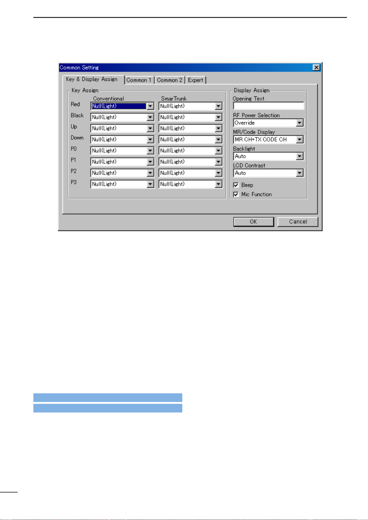
3-1 KEY & DISPLAYASSIGN— continued
The following functions can be assigned for the
SmarTrunk columns operation only.
Trunking Group SW:
Selects trunking group.
Turbo SpeeDial A, B, C, D:
Immediately calls commonly used telephone or subscriber numbers during
SmarTrunk II operation. See pages 50–52
for details
✽, # : Acts as [✽] or [#] keys on 10-key pad.
Convenient during SmarTrunk II operation
with non-keypad type transceivers (ICF3GS/F4GS).
Assign these functions to the keys which
[CH Up] or [CH Down] is assigned in conventional operation.
■ Display Assign
• Opening Text
Enter up to a 7-character transceiver opening message.
The usable characters are A–Z (uppercase), 0–9, $, ’, (,
), –, /, <, =, >, @, [, \, ], _, {, |, } and ~.
• RF Power Selection
Selects transmit output power setting condition from
MR CH individual and Override.
Selected transmit output power level with the
[High/Low] switch is kept for all channels regardless of
the individual power setting programmed in RF PWR in
4/5 MEMORY CHANNEL
(LMR; p. 22/PMR; p. 29)
when ‘Override’ is selected. However, outputs selected
transmit output power level temporarily with the
[High/Low] switch when ‘MR CH Individual’ is selected.
The [High/Low] switch is assigned in this screen (p. 7).
Go to RF PWR— LMR
Go to RF PWR— PMR
Programming memory Speed Dial
q Push and hold the [✽] until a high-pitch beep is heard.
w Enter the memory location (0–9), the telephone or subscriber
number, then [1], [✽] (or [3], [✽] if for another system subscriber).
• A high-pitch beep informs successful programming.
• Memories [A]–[D] are used for the Turbo SpeeDial.
Note: This function is available for the IC-F3GT/F4GT only.
Go to High/Low
Page 14
12
COMMON SETTING
3
3-1 KEY & DISPLAYASSIGN— continued
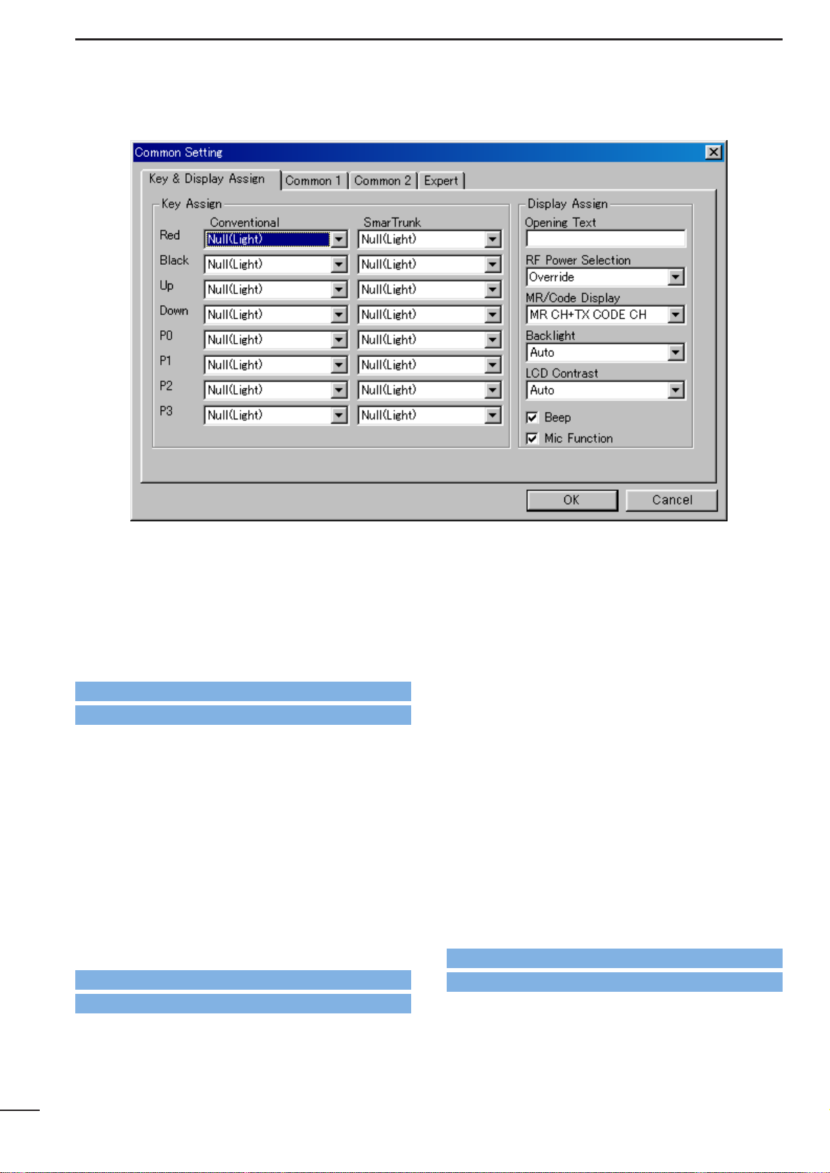
• MR/Code Display—
PMR only
Selects display conditions from MR CH, TX CODE CH
and MR CH+TX CODE CH.
MR CH
: The selected operating channel number or
programmed text is displayed.
TX CODE CH:
The selected transmit 5-tone code channel
number or programmed text is displayed.
MR CH+TX Code CH:
The selected transmit 5-tone code channel
number or programmed text is displayed after
operating channel number or programmed
text is briefly displayed.
Text for each operating channel and transmit 5-tone
code channel are programmed in Frequency— T extin
5 MEMORY CHANNEL
(p. 25) and in Text in
10-2 TX
CODE CHANNEL
(p. 43), respectively.
When no text is programmed, the selected channel
number is displayed instead of the text.
• Backlight
Selects LCD backlight lighting condition from ON, OFF
and Auto.
ON : Lights continuously while the transceiver is
powered ON.
OFF : Does not light with any operation.
Auto : Lights for 5 sec. when any switch except
[PTT] is pushed.
• LCD Contrast
Selects LCD contrast level from Low and Auto.
• Beep
Click the check-box to activate key-touch beep capability. (Not for lockout timer, TOT, etc.)
-The “✔” mark appears when checked.
• Mic Function
Click the check-box to activate the remote control
capability from an optional HM-75A SPEAKER MICRO-
PHONE.
[▲], [▼], [A] and [B] switches on the HM-75A operate
as [▲], [▼], [P0] and [P1] switches on the transceiver,
respectively.
-The “✔” mark appears when checked.
Go to Frequency— Text
Go to Text
Page 15
13
COMMON SETTING
3
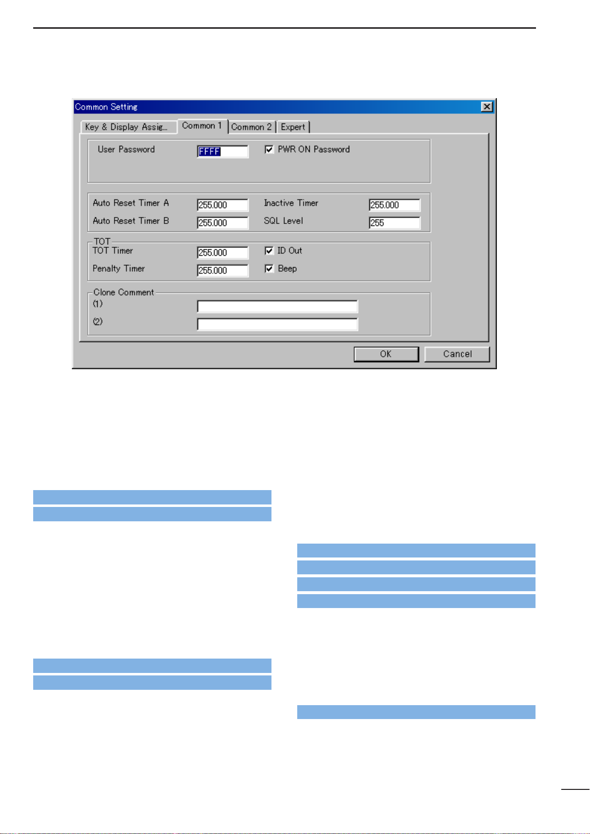
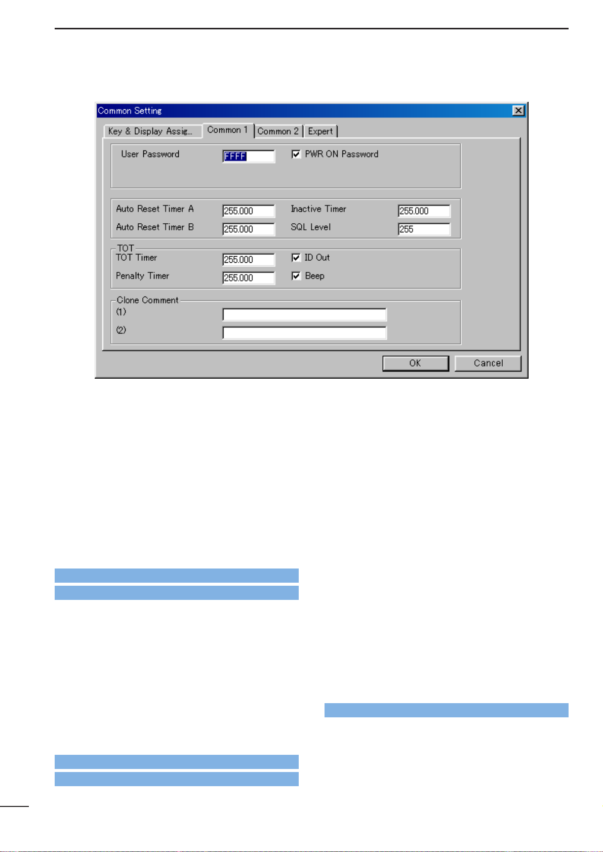
3-2 COMMON 1
• User Password
Enters up to a 4-digit user password for the power ON
password function or for cancelling the “Stun” condition.
The power ON password function is specified in PWR
ON Password as follows, and the “Stun” function is
specified in Stun in
9-1/10-1 RX CODE CHANNEL
(2-
tone; p. 39/5-tone; p. 42).
• PWR ON Password
Click the check-box to activate the power ON password function.
It is necessary to enter the 4-digit password programmed in the User Password as above when
checked. However, the password must be entered
after receiving a “Stun” signal regardless of this setting.
The Stun condition is programmed in Stun in
9-1/10-1
RX CODE CHANNEL
(2-tone; p. 39/5-tone; p. 42).
• Auto Reset Timer A, Auto Reset Timer B
Enter time
period for returning the mute condition to the
initial setting, specified in CH Mute in
5 MEMORY CH
(PMR only; p. 31), and/or restarting the scan from a
disappearing signal or when key operation is finished,
if the power ON scan function is turned ON.
To turn OFF the Auto Reset function, enter “0 (zero)” to
one of these settings. (“OFF” will be indicated)
The programmed settings are selected in Auto Reset
in
4/5 MEMORY CH
(LMR; p. 22/PMR; p. 31).
The power ON scan function is programmed in Power
ON Scan in
8-2 SCAN SETTING
(p. 37).
• Inactive Timer—
PMR only
The entered time period acts as the Auto Reset Timer A,
Auto Reset Timer B as above.
This setting is used with the Auto Rest Timer A or
Auto Rest Timer B, by selecting ‘Timer A Inact’ or
‘Timer B Inact’ in Auto Reset in
5 MEMORY CHAN-
NEL
(p. 31).
Go to Stun— 2-tone
Go to Stun— 5-tone
Go to Stun— 2-tone
Go to Stun— 5-tone
Go to CH Mute
Go to Auto Reset— LMR
Go to Auto Reset— PMR
Go to Power ON Scan
Go to Auto Reset— PMR
Page 16
14
SCREEN MENU OPERATION—LMR
3
3-2 COMMON 1— continued
• SQL Level
Enter a value within 0–255 range for noise squelch
threshold level adjustment.
• TOT— TOT Timer
Enters continuously transmittable time period (Time-out
timer)
. Maximum time period is specified for 30, 60 or
180 sec. etc., according to country and local regulation.
The time-out timer function can be turned ON or OFF
for each operating channel in TOT in
4/5MEMORY
CHANNEL
(LMR; p. 23/PMR; p. 31).
DO NOT set to only a few seconds, as transmitting will
be impossible.
• TOT— ID Out (DTMF)/ID Out
Click the check-box to activate the automatic ID transmission capability.
-The “✔” mark appears when checked.
The function automatically transmits an ID code when
the time-out timer activates, and just before transmission is inhibited.
The ID code is programmed in
No. Log/ID
in
6-1 DTMF
AUTODIAL
(p. 33) for LMR, and is specified in 5Tone
Signaling— ID in
5 MEMORY CHANNEL
(p. 29) for
PMR operation.
• TOT— Penalty Timer
Enters un-transmittable time period for penalty when
the continuously transmitted time has exceeded the
specified time period programmed in TOT— TOT
Timer as at left.
The TOT penalty time is the transmit inhibit period
when the time-out timer is activated.
• TOT— Beep
Click the check-box to activate the warning beep output capability for TOT function.
-The “✔” mark appears when checked.
Emits warning beep 10 sec. before compulsory shut
down of the transmission.
The transceiver emits warning beeps 10 sec. before,
and the time-out timer activates when this setting is
turned ON.
• Clone Comment— (1), (2)
Enters up to a 16-character text for quick identification
of a transceiver’s content.
The programmed comment of the connected transceiver can be checked without reading all other existing programmed data. See t CLONE MENU—
[Clone] in
2-1 MAIN SCREEN DESCRIPTION
(p. 3).
Go to TOT— LMR
Go to TOT— PMR
Go to 6-1 DTMF AUTODIAL
Go to 5Tone Signaling— ID
Go to CLONE MENU— [Clone]
Page 17
15
COMMON SETTING
3
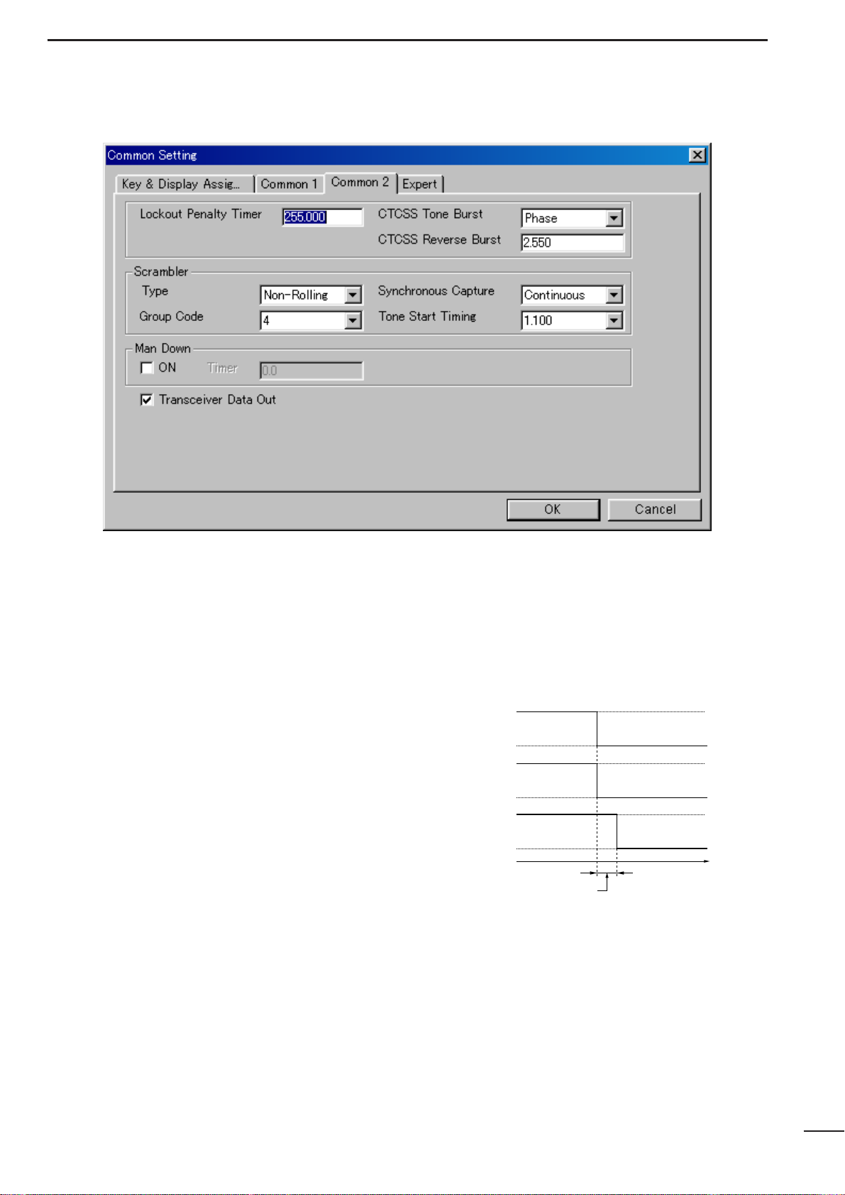
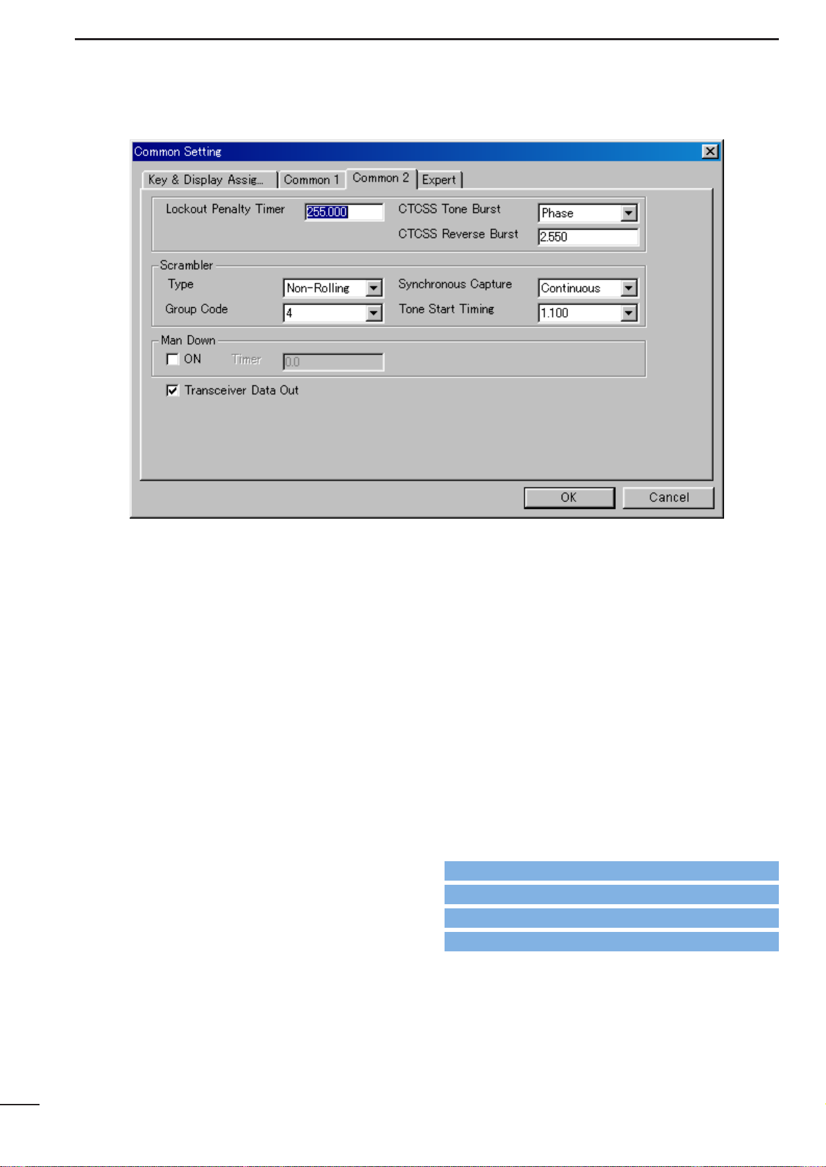
3-3 COMMON 2
• Lockout Penalty Timer
Enters un-transmittable time period for penalty when
transmitted on a busy channel. The un-transmittable
condition is kept for the programmed time period even
if the channel is cleared.
The lockout penalty time is the transmit inhibit period
when the user attempts to transmit while in a lockout
condition. The transmission is inhibited for the lockout
penalty time even when the lockout condition is
cleared.
• CTCSS Tone Burst
Selects tone burst system from Notone and Phase.
Notone : Un-modulates CTCSS encoder signal for the
specified time period, programmed in CTCSS
Reverse Burst in this screen as at right.
(This system is currently used.)
Phase : Reverses the phase of CTCSS encoder sig-
nal for the specified time period, programmed
in CTCSS Reverse Burst in this screen as at
right.
• CTCSS Reverse Burst
Enters time period for transmission delay with [PTT]
switch operation and CTCSS signal.
The transceiver still transmits for the programmed period without the CTCSS encoder or with phase reversed
CTCSS encoder signal after [PTT] is released. This
removes the transceiver’s ‘Squelch delay’.
• CTCSS Reverse Burst
Tone output
ON
OFF
RF power
output
ON
OFF
Time
PTT action
ON
OFF
CTCSS Reverse Burst
Page 18
16
SCREEN MENU OPERATION—LMR
4
3-3 COMMON 2— Continued
• Scrambler— Type
Selects scrambler type from Rolling and Non-Rolling.
Selects ‘Rolling’ when the optional voice scrambler
unit, UT-110 (#01), is installed, selects ‘Non-Rolling’
when UT-109 is installed.
UT-110 and UT-109 are not compatible due to different
scrambling systems. However, UT-110 can be used
instead of UT-109 by selecting ‘Non-Rolling’type in this
item
The Scrambler— Group Code as follows, must be pro-
grammed when UT-110 is used with the Rolling setting.
• Scrambler— Synchronous Capture
Selects synchronous capture mode from Standard and
Continuous.
It is recommended that ‘Standard’ is selected for simplex/normal operation, ‘Continuous’ for repeater operation.
• Scrambler— Group Code
Selects scrambler group code from 1, 2, 3 and 4 when
the optional voice scrambler unit, UT-110 (#01), is
installed and ‘Rolling’ is selected in the Scrambler—
Type as above.
Programming is not required when the optional voice
scrambler unit, UT-109, is installed.
• Scrambler— Tone Start Timing
Selects reference tone signal delay time from OFF,
0.3sec., 0.6 sec. and 1.1 sec.
The setting is used to synchronize voice scrambling
timing when the other stations/transceivers are in
power save mode.
• Man Down— ON, Timer
Click the check-box, ON, and enter time period in the
Timer column (25.5 sec. max.) to activate the man
down function when the optional UT-113 MAN DOWN UNIT
is installed.
The transceiver selects emergency channel and transmits an emergency signal automatically after passing
the programmed time period when the transceiver has
been left in a horizontal position.
The emergency channel is programmed in CH Atr in
4/5 MEMORY CHANNEL
(LMR; p. 19/PMR; p. 24).
For the emergency signal—
LMR : DTMF code of Emergency, programmed in
6-1
DTMF AUTODIAL
(p. 33), is used.
PMR : specified 5-tone/DTMF code selected in 5Tone
Signaling— STN in
5 MEMORY CHANNEL
(p. 29) of the emergency channel.
• Transceiver Data Out
Click the check-box to enable the transceiver’s programmed data out capability for both using this software and cloning between transceivers.
-The “✔” mark appears when checked.
The setting does not inhibit data writing, therefore over
writing data is still possible even when not checked.
Go to CH Atr— LMR
Go to CH Atr— PMR
Go to 6-1 DTMF AUTODIAL
Go to 5Tone Signaling— STN
Page 19
17
COMMON SETTING
3
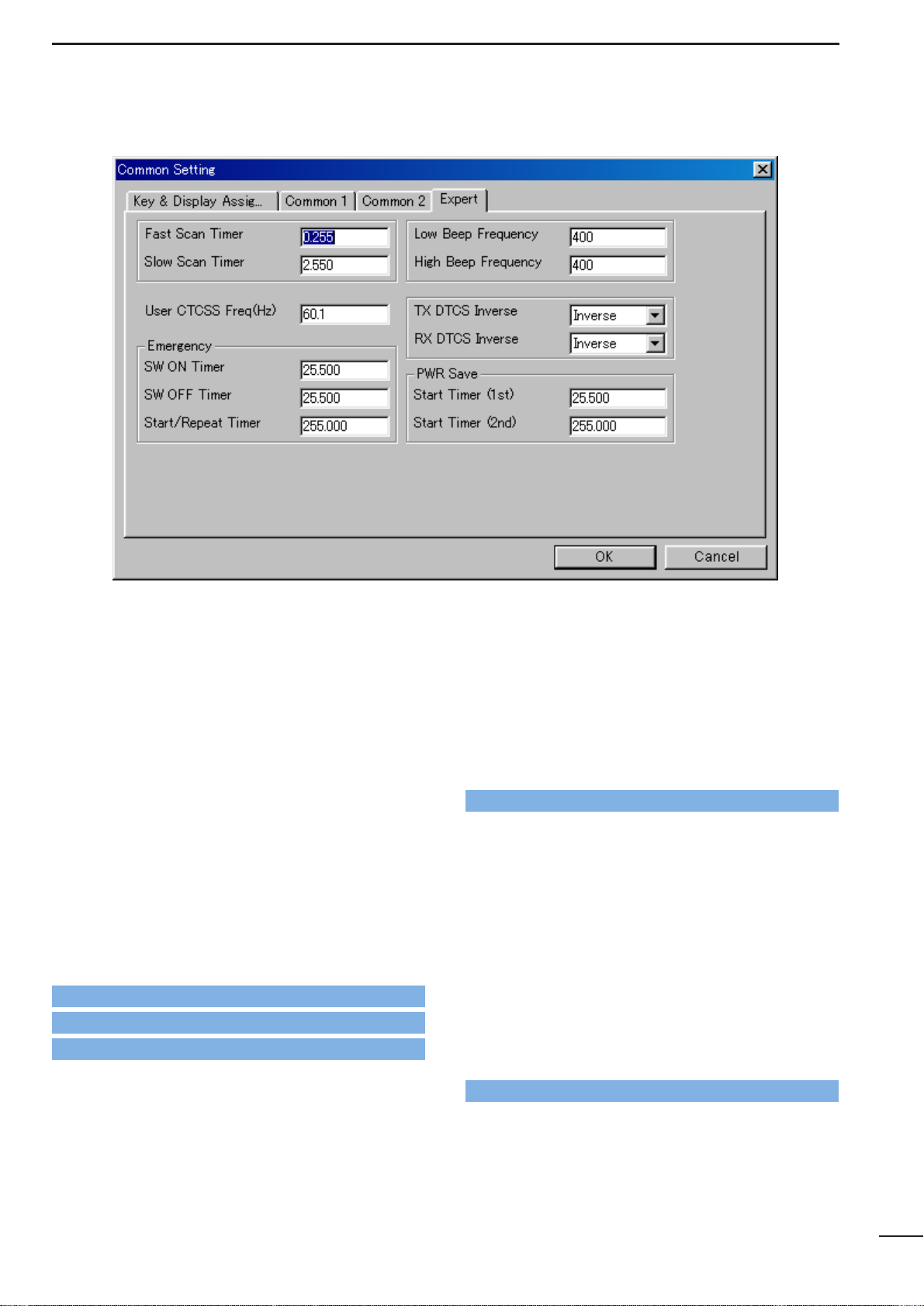
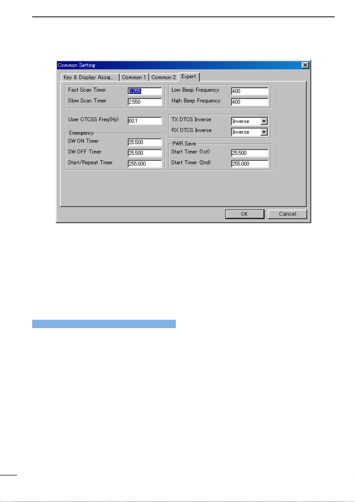
3-4 EXPERT
• Fast Scan Timer
Enters time period for scanning of each channel without CTCSS/DTCS programming.
An appropriate time is set by default and scan may not
stop when setting a value less than the default.
• Slow Scan Timer
Enters time period for scanning of each channel with
CTCSS/DTCS programming.
An appropriate time is set by default and scan may not
stop when setting a value less than the default.
• User CTCSS Freq(Hz)
Programs additional customer/system own CTCSS frequency to the existing 51 CTCSS frequencies within
60.1 to 300.1 Hz range.
The programmed CTCSS frequency can be selected in
C.Tone— RX and TX in
4/5 MEMORY CHANNEL
(LMR; p. 20/PMR; p. 26), and RX, TX in
7 CONTINU-
OUS TONE
(p. 35) by selecting ‘USER’.
• Emergency— SW ON Timer
Enters time period for which [Emergency Repeat] or
[Emergency Single] switch must be held to activate the
emergency function.
Push and hold [Emergency Repeat] or [Emergency
Single] switch for the programmed time period to make
an emergency call.
[Emergency Repeat] or [Emergency Single] switch is
assigned in
3-1 KEY & DISPLAY ASSIGN
(p. 9).
• Emergency— SW OFF Timer
Enters time period for which [Emergency Repeat] or
[Emergency Single] switch must be held to cancel the
emergency function.
Push and hold [Emergency Repeat] or [Emergency
Single] switch for the programmed time period to cancel an emergency call before an emergency signal is
transmitted.
However, once an emergency call is transmitted, the
call cannot be cancelled regardless of this setting.
[Emergency Repeat] or [Emergency Single] switch is
assigned in
3-1 KEY & DISPLAY ASSIGN
(p. 9)
Go to Emergency Repeat, Emergency Single
Go to Emergency Repeat, Emergency Single
Go to C.Tone— RX and TX— LMR
Go to C.Tone— RX and TX— PMR
Go to RX, TX
Page 20
18
COMMON SETTING
3
3-4 EXPERT— continued
• Emergency— Start/Repeat Timer
Enter the time periods for the emergency call delay
and interval.
The transceiver makes an emergency call after passing the programmed time period when the emergency
function is activated.
The transceiver transmits an emergency signal repeatedly at this interval until an “Emergency Cancel” code
is received when [Emergency Repeat] is used.
[Emergency Repeat] or [Emergency Single] switch is
assigned in
3-1 KEY & DISPLAY ASSIGN
(p. 9).
• Low Beep Frequency, High Beep Frequency
Enter beep audio frequency for each Low (for error) and
High (for regular) beep within 400 to 2998 Hz range,
respectively.
The nearest available frequency is selected automatically.
• TX DTCS Inverse
Selects the transmit DTCS code polarity.
In order for the transceiver to communicate using a
DTCS code, the polarity of the transmitting transceiver’s transmit code must be the same as the polarity of
the receiving transceiver’s receive code.
• RX DTCS Inverse
Selects the receive DTCS code polarity.
In order for transceivers to communicate using DTCS
codes, the polarity of the receiving transceiver’s
receive code must be the same as the polarity of the
transmitting transceiver’s transmit code.
• PWR Save— Start Timer (1st), (2nd)
Enter the time period for the power saver function start
timers within 0–25.5 sec. for the 1st, and 1–255 sec. or
OFF (enter ‘OFF’, when ‘OFF’ is selected) for the 2nd
timer.
The 1st timer must be set smaller than the 2nd timer,
due to the fact that the 2nd timer/power saver function
activates after the 1st timer/power saver. Otherwise
the 1st timer does not activate. The 2nd timer will be
set to ‘OFF’ when the UT-110 voice scrambler unit is
installed. The long timer setting will be invalid.
Go to Emergency Repeat, Emergency Single
Page 21
MEMORY CHANNEL— LMR
4
19
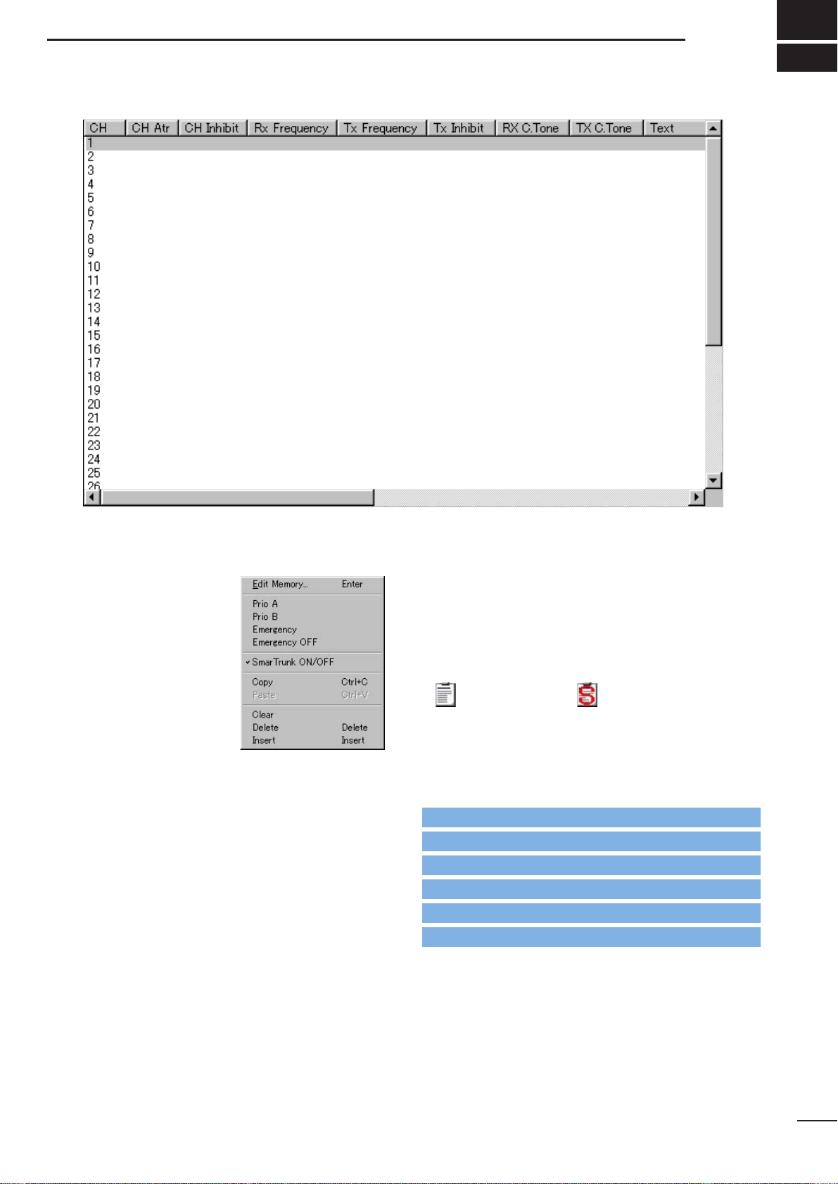
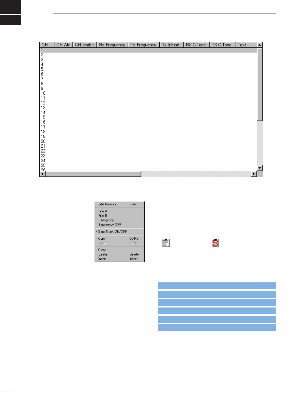
• CH Atr
Selects the channel attribution from Prio A, Prio B,
Emergency , Emergency OFF and SmarT runk ON/OFF.
Right click on the desired
channel to open the submenu window as at right, then
select the channel attribution.
A: Priority— “A” tagged channel becomes a priority
channel A, simply recalled by pushing [Priority A]
or [Priority A (Rewrite)] switch and also is automatically monitored during the priority scan.
When [Priority A (Rewrite)] switch is assigned,
priority channel A can be re-assigned by pushing
[Priority A (Rewrite)] switch for 1 sec..
B: Priority— “B” tagged channel becomes a priority
channel B, simply recalled by pushing [Priority B]
switch.
E: Emergency— “E” tagged channel becomes an
emergency channel, immediately recalled and
sends an emergency signal by pushing
[Emergency Single] or [Emergency Repeat]
switch, or when the man down function is activat-
ed. Only 1 channel can be set.
Emergency OFF— Regular channel.
SmarTrunk ON/OFF— Specifies the selected bank
for SmarTrunk operation.
This selection appears only when either 8CH*5Bank,
16CH*2Bank + 8CH or 20CH*2Bank type is selected in the BANK menu (p. 3) or, double click the bank
item in the Bank Setting in Memory Channel folder
indicated in the Tree View Screen (p. 4).
SmarTrunk specified bank/s, the bank item in the
Memory Channel folder, displayed in the Tree View
Screen, changes from regular to SmarTrunk type as
follows for easy recognition.
: Regular type : SmarTrunk type
[Priority A], [Priority A (Rewrite)], [Priority B],
[Emergency Single] and [Emergency Repeat] switches
are assigned in
3-1 KEY & DISPLA YASSIGN
(pgs. 7, 9).
The man down function is specified in Man Down—
ON, Timer in
3-3 COMMON 2
(p. 16)
The channel attribution can only be set on the Memory
Channel Screen as shown above. (Cannot be set in
the Edit window.) However, the other items are programmable in the Edit window only.
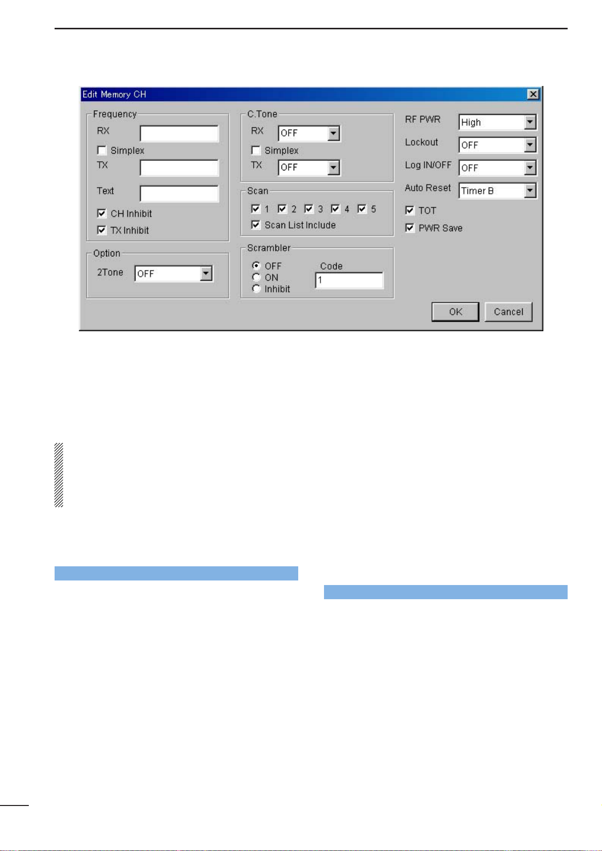
The Edit window appears by pushing the [Enter] key,
double clicking or selecting in the sub menu window
via the right click operation with the mouse on the
desired channel.
Go to Emergency Single, Emergency Repeat
Go to Prio A (Rewrite)
Go to Prio A, Prio B
Go to w Memory Channel
Go to u BANK MENU
Go to Man Down— ON, Timer
Page 22
20
MEMORY CHANNEL— LMR
4
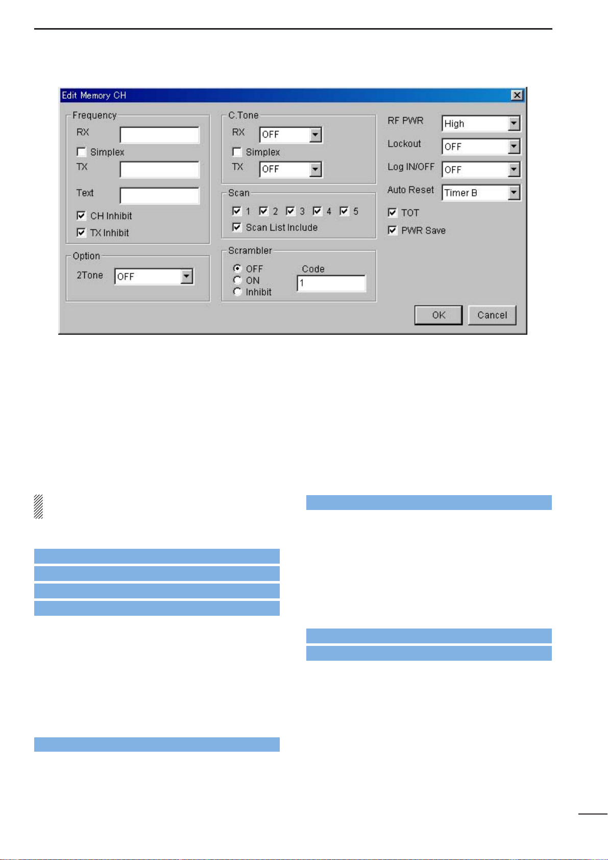
• Frequency— RX, TX
Enter receive and transmit frequencies within the following frequency range in either 5, 6.25 or 7.5 kHz
steps* for the RX and TX boxes, respectively.
IC-F3GT/GS : 136–150, 146–174 MHz
IC-F4GT/GS : 400–430, 440–470, 470–500,
490–512 MHz
*according to version
When no receive frequency is entered, other items
cannot be programmed in the channel.
When SmarTrunk ON/OFF is selected for the editing
bank in CH Atr (p. 19), operating frequencies must
be programmed from channel 1 without a blank.
When programming a simplex channel (transmit and
receive frequencies are the same), checks the simplex
check-box for instant setting after receive frequency is
programmed as follows.
• Frequency— Simplex
Click the check-box when the same frequency as the
receive is used for the transmit.
-The “✔” mark appears in the check-box when checked.
• Frequency— Text
Enter up to a 7-character text in the Text box for memory name, channel usage, etc.
The usable characters are A–Z, 0–9, $, ’, (, ), –, /, <, =,
>, @, [, \, ], _, {, |, } and ~.
When no text is entered, the channel number is indicated.
• Frequency— CH Inhibit
Click the check-box when the channel is to be inhibited.
The channel never appears on the transceiver, even if
all the other items are programmed when the channel
is inhibited.
-The “✔” mark appears in the check-box when checked.
• Frequency— TX Inhibit
Click the check-box when transmission inhibit is necessary.
-The “✔” mark appears when checked.
• Option— 2Tone
Selects 2-Tone code channel for reception with transceiver’s action when a matched 2-tone code is
received from OFF, 1, 2 and 3.
OFF : Nothing changes.
1, 2, 3: Activates a specified channel 1, 2 or 3 as pro-
grammed in the
9-1 RX CODE CHANNEL
(p. 38).
• C.Tone— RX, TX
Selects desired CTCSS frequency from the list or enter
a 3-digit DTCS code with polarity,
N (Normal) or I
(Inverse),
for receive and transmit in the RX and TX
boxes,
respectively.
When programming the same continuous tone as the
receive for the transmission, checks the simplex
check-box for instant setting after receive frequency is
programmed as follows.
• C.Tone— Simplex
Click the check-box when the same continuous tone as
the receive is used for the transmission.
-The “✔” mark appears in the check-box when checked.
Go to CH Atr
Go to 9-1 RX CODE CHANNEL
Page 23
21
MEMORY CHANNEL— LMR
4
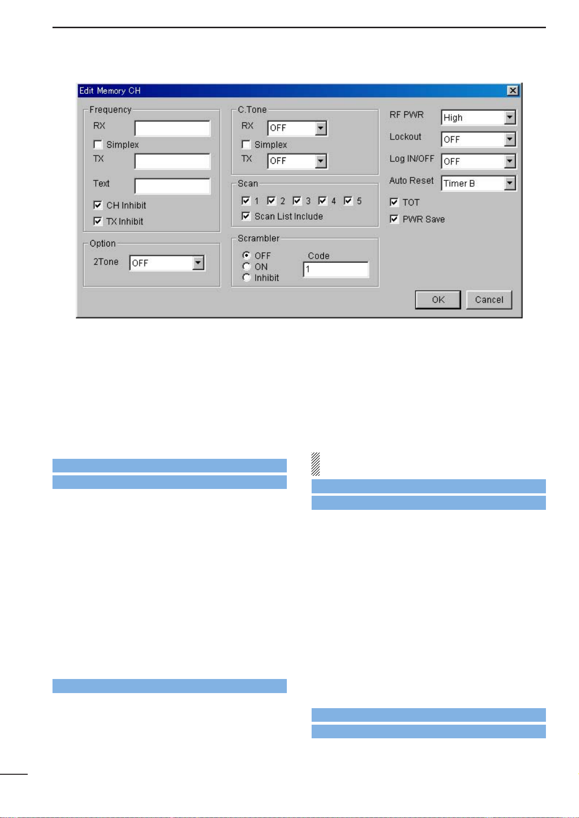
• Scan— 1–5
Click the check-box to the channel included into the
desired scan list (scanning group) 1–5.
Only the checked channels in the same scan list are
scanned when [Scan A] or [Scan B] switch is pushed.
-The “✔” mark appears in the check-box when checked.
The scan list (scanning group) is selectable via
[CH Up] or [CH Down] switches, after [Scan A] or
[Scan B] switch is pushed for 1 sec..
The scanning conditions for each scan list are specified in
8 SCAN LIST
(pgs. 36–37).
When SmarTrunk ON/OFF is selected for the editing
bank in CH Atr (p. 19), all boxes must be blank.
[CH Up], [CH Down], [Scan A] or [Scan B] switch is
assigned in
3-1 KEY & DISPLAY ASSIGN
(p. 6).
• Scan— Scan List Include
Click the check-box to enable scanning channel modification from the transceiver’s keypad.
The desired channel can be added or deleted to/from
the selected scan list by pushing [Scan Add/Del(Tag)]
switch.
[Scan Add/Del(Tag)] switch is assigned in
3-1 KEY &
DISPLAY ASSIGN
(p. 7).
• Scrambler— OFF, ON, Inhibit
Click to select voice scrambling function initial setting
from OFF, ON and Inhibit.
When OFF or ON is selected, the voice scrambling
function can be manually switched with the [Scrambler]
switch, however, the function cannot be manually
switched ON when Inhibit is selected.
An optional UT-109 or UT-110 VOICE SCRAMBLER UNIT is
required.
The [Scrambler] switch is assigned in
3-1 KEY & DIS-
PLAY ASSIGN
(p. 10).
• Scrambler— Code
Enter voice scrambling code within 1–32 using UT-109
or UT-110 with ‘Non-Rolling’ selection or within 1–255
using UT-110 with ‘Rolling’ selection installed.
In addition, the Scrambler— Group Code in
3-3
COMMON 2
(p. 16) must be programmed when UT-
110 is installed and ‘Rolling’ is selected in
Scrambler— Type in
3-3 COMMON 2
(p. 16).
Go to 8 SCAN LIST
Go to CH Atr
Go to CH Up, CH Down
Go to Scan Add/Del(Tag)
Go to Scrambler
Go to Scrambler— Group Code
Go to Scrambler— Type
Go to Scan A, Scan B
Page 24
22
MEMORY CHANNEL— LMR
4
• RF PWR
Selects transmit output power for initial setting from
High and Low.
The selected output power setting for each channel
can be switched to either temporary or permanent
operation, according to the setting in the RF Power
Selection in
3-1 KEY & DISPLAY ASSIGN
(p. 11) via
[High/Low] switch.
The [High/Low] switch is assigned in the
3-1 KEY &
DISPLAY ASSIGN
(p. 7)
• Lock out
Selects transmission lock out (temporary transmission
inhibit)
capability from OFF, Busy and Rpt (Repeater).
OFF : No restriction for receiving a signal.
Busy : [PTT] switch cannot be activated while the
operating channel/repeater is in use.
Rpt : [PTT] switch can be activated while receiving
a signal with matched CTCSS (or DTCS)
tone or no signals.
In addition, [PTT] switch is not activated for an extra
time period in the case of when the lockout penalty
timer, programmed in the Lockout Penalty T imer in
3-
3 COMMON 2
(p. 15), is activated, even if the trans-
ceiver in a transmittable condition.
• Log IN/OFF
Selects automatic ID transmission condition in relation
with [PTT] from L-IN, L-OFF, Both and OFF.
OFF : No ID is transmitted with [PTT].
L-IN : ID is transmitted each time [PTT] is pushed.
L-OFF: ID is transmitted each time [PTT] is released.
Both : ID is transmitted each time [PTT] is pushed
and released.
Log/ID code is used as the ID code, programmed in
6-
1 DTMF AUTODIAL
(p. 33).
When SmarTrunk ON/OFF is selected for the editing
bank in CH Atr (p. 19), “OFF” must be selected.
• Auto Reset
Selects reset timer from Timer A and Timer B for
restarting scanning when the power ON scan function
is activated
Timer A, Timer B:
Restarts scanning after specified time period
(Timer A or Timer B) has passed from a disap-
pearing signal or key operation is finished.
The time period of Timer A and Timer B are programmed in the Auto Reset Timer A, Auto Reset
Timer B in
3-2 COMMON 1
(p. 13), respectively.
To turn OFF the function, select the timer which OFF
(0 sec.) is programmed.
The power ON scan function is specified in the Power
ON Scan in
8-2 SCAN SETTING
(p. 37).
Go to RF Power Selection
Go to High/Low
Go to Lockout Penalty Timer
Go to CH Atr
Go to 6-1 DTMF AUTODIAL
Go to Power ON Scan
Go to Auto Reset Timer A, Auto Reset Timer B
Page 25
MEMORY CHANNEL— LMR
4
23
•TOT
Click the check-box to activate the time-out timer function.
-The “✔” mark appears when TOT function is activated.
Continuously transmittable time is limited by the timer
during activation. However, time-out timer must be
activated due to local regulation, in some countries.
The time period is programmed in the TOT— TOT
Timer in
3-2 COMMON 1
(p. 14).
When SmarTrunk ON/OFF is selected for the editing
bank in CH Atr (p. 19), “OFF” must be selected.
• PWR Save
Click the check-box to activate the power save function.
-The “✔” mark appears when the power save function is
activated.
The power save start times are programmed in the
PWR Save— Start Timer (1st), (2nd) in
3-4 EXPERT
(p. 18).
When SmarTrunk ON/OFF is selected for the editing
bank in CH Atr (p. 19), “OFF” must be selected.
Go to CH Atr
Go to TOT— TOT Timer
Go to CH Atr
Go to PWR Save— Start Timer (1st), (2nd)
Page 26
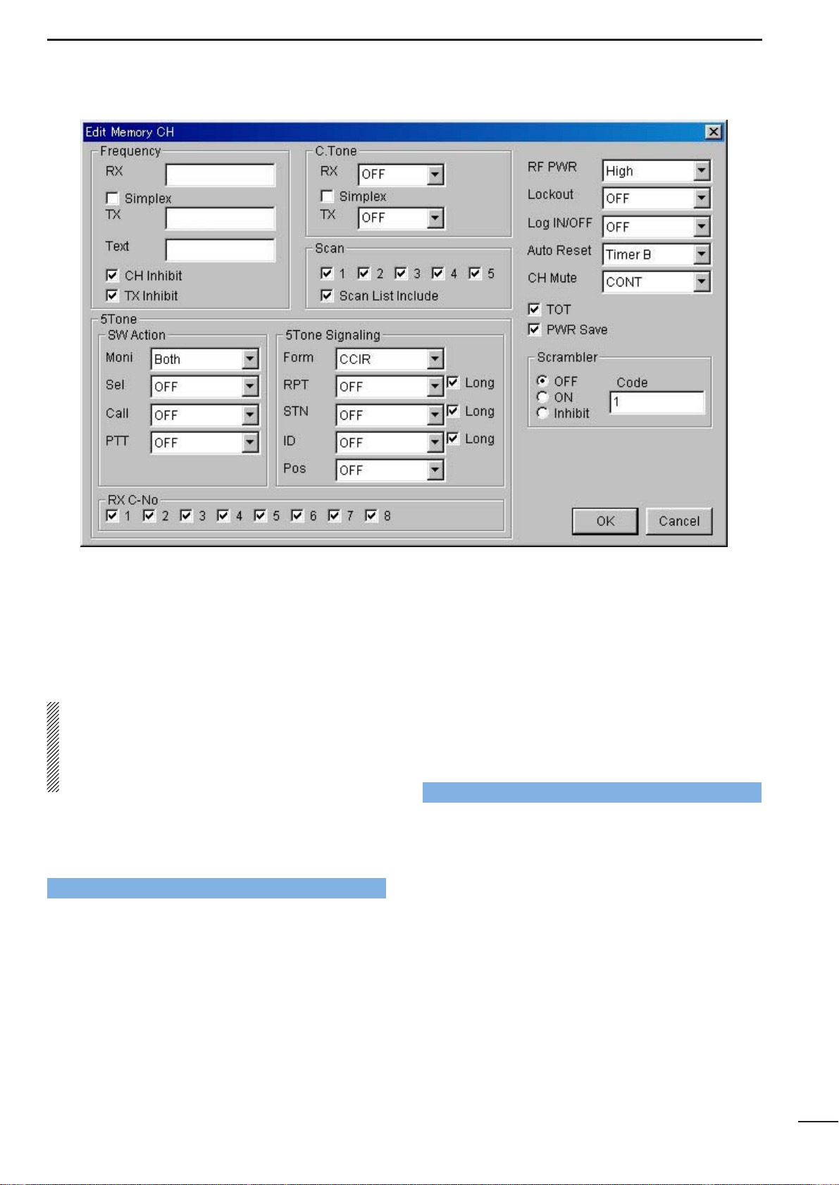
MEMORY CHANNEL— PMR
5
24
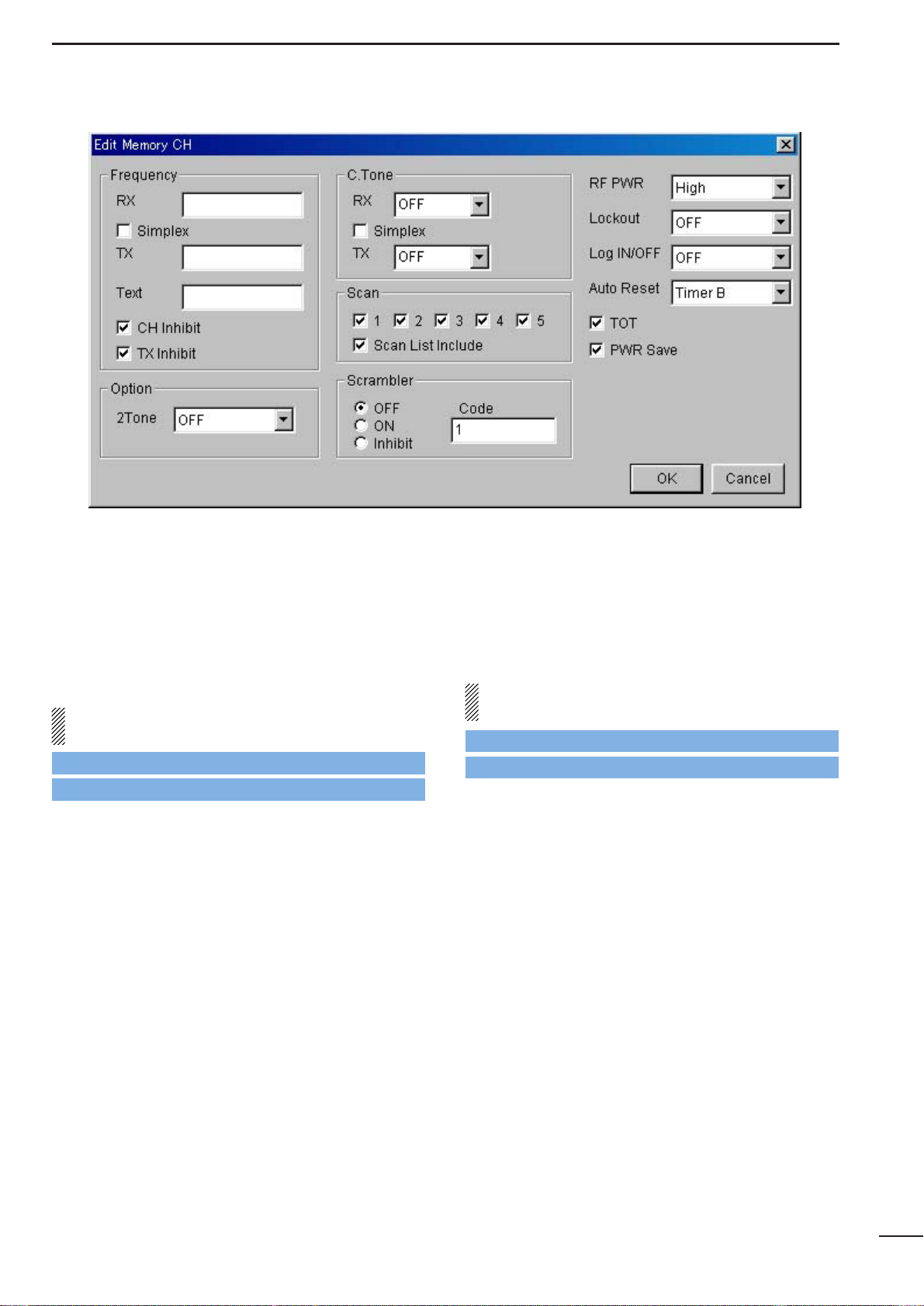
• CH Atr
Selects the channel attribution from Prio A, Prio B,
Emergency , Emergency OFF and SmarT runk ON/OFF.
Right click on the desired
channel to open the submenu window as at right, then
select the channel attribution.
A: Priority— “A” tagged channel becomes a priority
channel A, simply recalled by pushing [Priority A]
or [Priority A (Rewrite)] switch and also is automatically monitored during the priority scan.
When [Priority A (Rewrite)] switch is assigned,
priority channel A can be re-assigned by pushing
[Priority A (Rewrite)] switch for 1 sec..
B: Priority— “B” tagged channel becomes a priority
channel B, simply recalled by pushing [Priority B]
switch.
E: Emergency— “E” tagged channel becomes an
emergency channel, immediately recalled and
sends an emergency signal by pushing
[Emergency Single] or [Emergency Repeat]
switch, or when the man down function is activat-
ed. Only 1 channel can be set.
Emergency OFF— Regular channel.
SmarTrunk ON/OFF— Specifies the selected bank
for SmarTrunk operation.
This selection appears only when either 8CH*5Bank,
16CH*2Bank + 8CH or 20CH*2Bank type is selected in the BANK menu (p. 3) or, double click the bank
item in the Bank Setting in Memory Channel folder
indicated in the Tree View Screen (p. 4).
SmarTrunk specified bank/s, the bank item in the
Memory Channel folder, displayed in the Tree View
Screen, changes from regular to SmarTrunk type as
follows for easy recognition.
: Regular type : SmarTrunk type
[Priority A], [Priority A (Rewrite)], [Priority B],
[Emergency Single] and [Emergency Repeat] switches
are assigned in
3-1 KEY & DISPLA YASSIGN
(pgs. 7, 9).
The man down function is specified in Man Down—
ON, Timer in
3-3 COMMON 2
(p. 16).
The channel attribution can only be set on the Memory
channel Screen as shown above. (Cannot be set in the
Edit window.) However, the other items are programmable in the Edit window only.
The Edit window appears by pushing the [Enter] key,
double clicking or selecting in the sub menu window
via the right click operation with the mouse on the
desired channel.
Go to Emergency Single, Emergency Repeat
Go to Prio A (Rewrite)
Go to Prio A, Prio B
Go to w Memory Channel
Go to u BANK MENU
Go to Man Down— ON, Timer
Page 27
25
SCREEN MENU OPERATION— PMR
5
• Frequency— RX, TX
Enter receive and transmit frequencies within the following frequency range in either 5, 6.25 or 7.5 kHz
steps* for the RX and TX boxes, respectively.
IC-F3GT/GS : 136–150, 146–174 MHz
IC-F4GT/GS : 400–430, 440–470, 470–500,
490–520 MHz
*according to version
When no receive frequency is entered, other items
cannot be programmed in the channel.
When SmarTrunk ON/OFF is selected for the editing
bank in CH Atr (p. 24), operating frequencies must
be programmed from channel 1 without a blank.
When programming a simplex channel (transmit and
receive frequencies are the same), checks the simplex
check-box for instant setting after receive frequency is
programmed as follows.
• Frequency— Simplex
Click the check-box when the same frequency as the
receive is used for the transmit.
-The “✔” mark appears in the check-box when checked.
• Frequency— Text
Enter up to a 7-character text for memory name, channel usage indication, etc..
The usable characters are A–Z, 0–9, $, ’, (, ), –, /, <, =,
>, @, [, \, ], _, {, |, } and ~.
When no text is entered, the channel number is indicated.
The programmed text is indicated during operation or
briefly indicated after operating channel selection when
‘MR CH’ or ‘MR CH+TX CODE CH’ is selected in
MR/Code Display in
3-1 KEY & DISPLAY ASSIGN
(p. 12).
• Frequency— CH Inhibit
Click the check-box when the channel is to be inhibited.
The channel never appears on the transceiver, even if
all the other items are programmed when the channel
is inhibited.
-The “✔” mark appears in the check-box when checked.
• Frequency— TX Inhibit
Click the check-box when transmission inhibit is necessary.
-The “✔” mark appears when checked.
Go to CH Atr
Go to MR/Code Display
Page 28
26
SCREEN MENU OPERATION— PMR
5
• C.Tone— RX, TX
Selects desired CTCSS frequency from the list or enter
a 3-digit DTCS code with polarity,
N (Normal) or I
(Inverse),
for receive and transmit in the RX and TX
boxes,
respectively.
When programming the same continuous tone as the
receive for the transmission, checks the simplex
check-box for instant setting after receive frequency is
programmed as follows.
• C.Tone— Simplex
Click the check-box when the same continuous tone as
the receive is used for the transmission.
-The “✔” mark appears when checked.
• Scan— 1–5
Click the check-box to the channel included in to the
desired scan list (scan group) 1–5.
Only the checked channels in the same scan list are
scanned when [Scan A] or [Scan B] switch is pushed.
-The “✔” mark appears when checked.
The scan list (scanning group) is selectable via
[CH Up] or [CH Down] switches, after [Scan A] or
[Scan B] switch is pushed for 1 sec..
The scanning conditions for each scan list are specified in
8 SCAN LIST
(pgs. 36–37).
When SmarTrunk ON/OFF is selected for the editing
bank in CH Atr (p. 24), all boxes must be blank.
[CH Up], [CH Down], [Scan A] or [Scan B] switch is
assigned in
3-1 KEY & DISPLAY ASSIGN
(p. 6).
• Scan— Scan List Include
Click the check-box to enable scanning channel modification from the transceiver’s key.
The desired channel can be added or deleted to/from
the selected scan list by pushing [Scan Add/Del(Tag)]
switch.
[Scan Add/Del(Tag)] switch is assigned in
3-1 KEY &
DISPLAY ASSIGN
(p. 7).
Go to 8 SCAN LIST
Go to CH Atr
Go CH Up, CH Down
Go to Scan Add/Del(Tag)
Go to Scan A, Scan B
Page 29
SCREEN MENU OPERATION— PMR
27
5
• SW Action— Moni
Selects [Moni(Audi)] switch action from OFF, Aud, In A,
In A+R1, In A+R2, Both, Both+R1 and Both+R2.
OFF : Releases both noise and CTCSS/DTCS
squelch mute while pushing and holding
[Moni(Audi)] switch. There is no audio output
when 5-tone mute is activated on the channel.
Aud : Releases the 5-tone mute only when ‘SGL’ is
selected in CH Mute (p. 31) in this screen, by
pushing [Moni(Audi)] switch for 1 sec..
Both CTCSS/DTCS and noise squelch mutes
are released (audio is emitted) while pushing
and holding [Moni(Audi)] switch when 5-tone
mute is released or ‘CONT’ is selected in CH
Mute (p. 31) in this screen.
In A : Mutes the 5-tones when ‘SGL’ is selected in
CH Mute (p. 31) in this screen by pushing
[Moni(Audi)] switch.
Both CTCSS/DTCS and noise squelch mutes
are released (audio is emitted) while pushing
and holding [Moni(Audi)] switch while 5-tone
mute is activated.
In A+R1, In A+R2:
In addition to the ‘In_A’ condition as above, a
reset code 1 or 2 is automatically transmitted
when call transmission is performed or 5-tone
mute is activated by pushing [Moni(Audi)]
switch.
Both : Mutes the 5-tones when ‘SGL’ is selected in
CH Mute (p. 31) in this screen by pushing
[Moni(Audi)] switch.
Releases 5-tone mute when ‘SGL’is selected
in CH Mute (p. 31) in this screen by pushing
[Moni(Audi)] switch for 1 sec.
Releases all mute controls and emits audio
while pushing and holding [Moni(Audi)]
switch.
Both+R1, Both+R2:
In addition to the ‘Both’ condition as above, a
reset code 1 or 2 is automatically transmitted
when call transmission is performed via [Call]
switch or 5-tone mute is activated by pushing
[Moni(Audi)] switch.
The [Moni(Audi)] and [Call] switches are assigned in
the
3-1 KEY & DISPLAY ASSIGN
(pgs. 7, 8).
The reset code 1 and 2 are programmed in
10-2 TX
CODE CHANNEL
(p. 43), and channels 32 (reset code
1)
and 31 (reset code 2) are used, respectively.
The mute condition will be returned to initial condition
when the Auto Reset timer is activated, specified in
Auto Reset in this screen (p. 31).
Go to CH Mute
Go to Moni(Audi)
Go to Call
Go to 10-2 TX CODE CHANNEL
Go to Auto Reset
Page 30
28
SCREEN MENU OPERATION— PMR
5
• SW Action— Sel
Selects mute condition after memory channel selection
from OFF, Aud and In A.
OFF : Dose not change even when selecting
memory or TX code channel.
Aud : Releases the 5-tone mute when ‘SGL’ is
selected in CH Mute (p. 31) in this screen.
In A : Mutes the 5-tones when ‘SGL’ is selected in
CH Mute (p. 31) in this screen.
The mute condition will be returned to initial condition
when the Auto Reset timer is activated, specified in
Auto Reset in this screen (p. 31).
• SW Action— Call, PTT
Selects mute condition after [Call] and [PTT] switches
action from Aud and OFF.
OFF : Does not change when transmitting with
[Call]/[PTT] transmission.
Aud : Releases the 5-tone mute when ‘SGL’ is
selected in CH Mute (p. 31) in this screen
after any [Call]/[PTT] transmission.
Select OFF for both the SW Action— Call and PTT,
when the ABC— Aud in
10-2 TX CODE CHANNEL
(p. 44) is activated, and select OFF for the SW
Action— PTT, when the PTT Call at Inaudible in
10-5
5TONE SETTING
(p. 48) is activated.
The [Call] switch is assigned in the
3-1 KEY & DIS-
PLAY ASSIGN
(p. 8).
The mute condition will be returned to initial condition
when the Auto Reset timer is activated, specified in
Auto Reset in this screen (p. 31).
• 5Tone Signaling— Form
Selects 5-tone system format from USER, CCIR,
ZVEI1, ZVEI2, DZVEI, EEA, EEA2, DAPL, EIA and
DTMF.
When the DTMF decoder operation is required (UT108 must be installed), select DTMF in this item.
Go to CH Mute
Go to Auto Reset
Go to CH Mute
Go to Go to ABC— Aud
Go to Call
Go to PTT Call at Inaudible
Page 31

29
SCREEN MENU OPERATION— PMR
5
• 5Tone Signaling— RPT, STN, ID
Selects 5-tone code channel for repeater (RPT), individual station/group (STN) access and own identity (ID),
respectively.
These 5-tone codes are programmed in TX Code in
10-2 TX-CODE CHANNEL
(p. 43).
• 5Tone Signaling— Pos
Selects the own ID code sending sequence from OFF,
BTM and TOP.
OFF : Does not send the ID code.
BTM : Sends the ID code after sending station or
group code.
TOP : Sends the ID code before sending station or
group code.
• 5Tone Signaling— Long
Click the check-box to activate the long tone capability
for each 5-tone code, RPT, STN and ID, respectively.
-The “✔” mark appears when long tone is activated.
The time period for the long tone is programmed in the
Long Tone Timer in
10-5 5TONE SETTING
(p. 47).
• RX C-No
Click the check-box to select the receive 5-tone code
channel to be decoded.
Up to 8 codes/channels can be selected to decode in
each operating channel.
The 5-tone code is programmed in RX Code in
10-1
RX CODE CHANNEL
(p. 41).
• RF PWR
Selects transmit output power for initial setting from
High and Low.
The selected output power setting for each channel
can be switched to either temporary or permanent
operation, according to the setting in the RF Power
Selection in
3-1 KEY & DISPLAY ASSIGN
(p. 11) via
[High/Low] switch.
The [High/Low] switch is assigned in the
3-1 KEY &
DISPLAY ASSIGN
(p. 7)
• ID code sending sequence diagram
TOP
Time
BTM
1 2 3 4 5 1 2 3 4 5 1 2 3 4 5
Repeater code
(if available)
Station/Group
code
ID code
1 2 3 4 5 1 2 3 4 5 1 2 3 4 5
Repeater code
(if available)
ID code
Station/Group
code
Go to Long Tone Timer
Go to TX Code
Go to RX Code
Go to RF Power Selection
Go to High/Low
Page 32

30
SCREEN MENU OPERATION— PMR
5
• Lock out
Selects transmission lock out (temporary transmission
inhibit)
capability from OFF, Busy, Rpt 1 and Rpt 2.
OFF : No restriction for receiving a signal.
Busy : [PTT] switch cannot be activated while the
operating channel/repeater is in use.
Rpt1 : [PTT] switch can be activated while receiving
a signal with matched CTCSS (or DTCS)
tone or no signals.
Rpt2 : [PTT] switch can be activated while receiving
a signal with matched CTCSS (or DTCS)
tone or no signals while 5-tone mute is
released, or receiving an unmatched CTCSS
(or DTCS) tone while 5-tone mute is activated.
In addition, [PTT] switch is not activated for an extra
time period in the case of when the lockout penalty
timer, programmed in the Lockout Penalty T imer in
3-
3 COMMON 2
(p. 15), is activated even if the trans-
ceiver in a transmittable condition.
• Log IN/OFF
Selects automatic ID transmission condition in relation
to [PTT] switch from OFF, L-IN, L-INA, L-INI, L-OFF, LOFFA, Both, BothA1 and BothA2.
OFF : No ID is transmitted with [PTT].
L-IN : ID is transmitted when [PTT] is pushed.
L-INA : ID is transmitted when [PTT] is pushed
while 5-tone mute is released.
L-INI : ID is transmitted when [PTT] is pushed
while 5-tone mute is activated. Voice transmission is impossible while 5-tone mute is
activated and ‘SGL’ is selected in CH Mute
(p. 31) in this screen.
L-OFF : ID is transmitted when [PTT] is released.
L-OFFA: ID is transmitted when [PTT] is released
while 5-tone mute is released.
Both : ID is transmitted when both [PTT] is pushed
and released.
BothA1 : ID is transmitted when both [PTT] is pushed
and released while 5-tone mute is released.
BothA2 : ID is transmitted when both [PTT] is pushed
and released while 5-tone mute is released.
ID is transmitted when [PTT] is pushed
while 5-tone mute is activated. Voice trans-
mission is impossible while 5-tone mute is
activated and when ‘SGL’ is selected in CH
Mute (p. 31) in this screen.
When SmarTrunk ON/OFF is selected for the editing
bank in CH Atr (p. 24), “OFF” must be selected.
The ID code is assigned in the 5Tone signaling— ID
column in this screen (p. 29), and the 5-tone code is
programmed in TX Code in
10-2 TX CODE CH
(p. 43).
Go to Lockout Penalty Timer
Go to CH Atr
Go to CH Mute
Go to TX Code
Go to 5Tone Signaling— ID
Page 33

31
SCREEN MENU OPERATION— PMR
5
• Auto Reset
Selects reset timer from Timer A, Timer B, Timer A
Inact and Timer B Inact.
Timer A, Time B:
Returns 5-tone mute condition to initial,
and
starts scanning,
if power ON scan function is
tuned ON, after specified time (Timer Aor B) has
passed from a disappearing signal, or when
key operation is finished.
Timer A Inact, Timer B Inact:
Returns 5-tone mute condition to initial after a
shorter time period (either Timer A/B or Inactive)
has passed from when 5-tone mute is
released. Automatically returns 5-tone mute
condition to initial as soon as transmission is
finished, and starts scanning after specified
time (Timer A or B) has passed.
The time period of Timer A, Timer B and Inactive timer
is programmed in the Auto Reset Timer A, Auto
Reset Timer B and Inactive Timer in
3-2 COMMON 1
(p. 13), respectively.
To turn OFF the function, select the timer which OFF
(0 sec.) is programmed.
The power ON scan function is specified in the Power
ON Scan in
8-2 SCAN SETTING
(p. 37).
5-tone mute initial condition is selected in CH Mute as
at above right.
• CH Mute
Selects 5-tone mute initial activity from CONT and
SGL.
CONT:
5-tone mute
is released.
SGL :
5-tone mute
is activated. In this case, [PTT]
switch action is inhibited while 5-tone mute is
activated.
•TOT
Click the check-box to activate the time-out timer function.
-The “✔” mark appears when TOT function is activated.
Continuously transmittable time is limited by the timer
during activation. However, time-out timer must be
activated due to local regulation, in some countries.
The time period is programmed in the TOT— TOT
Timer in
3-2 COMMON 1
(p. 14).
When SmarTrunk ON/OFF is selected for the editing
bank in CH Atr (p. 24), “OFF” must be selected.
Go to Inactive Timer
Go to Auto Reset Timer A, Auto Reset Timer B
Go to Power ON Scan
Go to TOT— TOT Timer
Go to CH Atr
Page 34

• PWR Save
Click the check-box to activate the power save function.
-The “✔” mark appears when the power save function is
activated.
The power save start times are programmed in the
PWR Save— Start Timer (1st), (2nd) in
3-4 EXPERT
(p. 18).
When SmarTrunk ON/OFF is selected for the editing
bank in CH Atr (p. 24), “OFF” must be selected.
• Scrambler— OFF, ON, Inhibit
Click to select voice scrambling function initial setting
from OFF, ON and Inhibit.
When OFF or ON is selected, the voice scrambling
function can be manually switched with the [Scrambler]
switch, however, the function cannot be manually
switched ON when Inhibit is selected.
An optional UT-109 or UT-110 VOICE SCRAMBLER UNIT is
required.
The [Scrambler] switch is assigned in
3-1 KEY & DIS-
PLAY ASSIGN
(p. 10).
• Scrambler— Code
Enter voice scrambling code within 1–32 using UT-109
or UT-110 with ‘Non-Rolling’ selection or within 1–255
using UT-110 with ‘Rolling’ selection installed.
In addition, the Scrambler Group Code in
3-3 COM-
MON 2
(p. 16) must be programmed when UT-110 is
installed and ‘Rolling’ is selected in Scrambler T ype in
3-3 COMMON 2
(p. 16).
32
SCREEN MENU OPERATION— PMR
5
Go to PWR Save— Start Timer (1st), (2nd)
Go to CH Atr
Go to Scrambler
Go to Scrambler Group Code
Go to Scrambler Type
Page 35

DTMF AUTODIAL
6
33
6-1 DTMF AUTODIAL
The IC-F3G series transceiver has total of 5 DTMF memory channels. The programmed DTMF codes are selected
and transmitted with simple operation. For the LMR, the programmed DTMF code in the Emergency and the Log/ID
autodial are used for Emergency call, man down function, and automatic ID transmission, respectively.
• Code
Enter up to a 24-digit DTMF code for simple and quick
DTMF code transmission.
The usable characters are 0–9, A–F (#/✽ used as F/E).
The programmed DTMF codes are selected via
[CH Up] or [CH Down] switch after pushing [DTMF
Autodial] switch.
The [CH Up], [CH Down] and [DTMF Autodial] switches are assigned in
3-1 KEY & DISPLAY ASSIGN
(pgs. 6, 8).
• Text
Enter up to a 7-character text for easy recognition of
DTMF code usage, etc.
When no text is programmed, the programmed DTMF
code is scrolled.
The usable characters are A–Z (uppercase), 0–9, $, ‘, (,
), –, /, <, =, >, @, [, \, ], _, {, |, } and ~.
Memory Channel Screen indication for LMR
Memory Channel Screen indication for PMR
Go to CH Up, CH Down
Go to DTMF Autodial
Page 36

34
DTMF AUTODIAL
6
6-2 DTMF SETTING
• DTMF Timer
Enter time period/signal length for each DTMF code
emission and interval.
• 1st Timer
Enter time period/signal length for 1st DTMF code
emission and interval corresponding to the scanning or
power saving of the transceiver.
•[✽] [#] Timer
Enter time period/signal length for [✽] and [#] DTMF
code signal emission and interval.
These codes may be used for control codes depending
on the signaling system.
When these special codes are used for the 1st digit
code, the 1st Timer as at left has priority over this setting.
Page 37

CONTINUOUS TONE
7
35
• RX, TX
Selects desired CTCSS frequency from the list or enter
a 3-digit DTCS code with polarity,
N (Normal) or I
(Inverse),
for receive and transmit in the RX and TX
boxes,
respectively.
When programming the same continuous tone as the
receive for the transmission, check the simplex checkbox for instant setting after RX is programmed as at
right.
The programmed continuous tone combinations can
be used for temporary encoder and/or decoder operation.
To use the programmed continuous tone;
Push [C. Tone CH Ent] switch, then select a continuous tone memory channel via [CH Up] or [CH Down]
switch.
[C. Tone CH Ent], [CH Up] and [CH Down] switches
are assigned in
3-1 KEY & DISPLAY ASSIGN
(pgs. 8,
6).
• Simplex
Click the check-box when the same continuous tone as
the receive is used for the transmission.
-The “✔” mark appears in the check-box when checked.
Memory Channel Screen indication
Go to CH Up, CH Down
The IC-F3G series transceiver has total of 9 continuous tone memory channels, in addition to the channel (operating channel) independent continuous tone operation. Separate continuous tone, CTCSS or DTCS for encoder and
decoder, can be programmed for each channel, and are operated temporarily or permanently.
Go to C.Tone CH Ent
Page 38

8-1 SCAN LIST
A total of 5 scanning lists/groups are available for a wide variety and flexible scanning operation. In this screen,
programs scanning conditions for each list/group.
• Mode
Selects scanning mode from Scan OFF, MODE 1,
MODE 2 and MODE 3.
Scan OFF: Scan function cannot be controlled from
the transceiver keypad.
MODE 1 : Normal scan. Scans all checked chan-
nels. The scan proceeds in sequence
from lower to higher channel number.
MODE 2 : Priority scan. The priority A channel is
monitored every fixed time period during
scan (depending on version), or every spec-
ified time period programmed in the Stop
Timer in
8-2 SCAN SETTING
(p. 37),
during pause. The busy or paused channel is retained when scan is cancelled.
MODE 3 : Priority scan. Same scanning sequence
as MODE 2 above. The priority channel is
retained when scan is cancelled.
The scanning channels are selected in Scan— 1–5 in
4/5 MEMORY CHANNEL
(LMR; p. 21/PMR; p. 26).
The priority A channel is selected in CH Atr in
4/5
MEMORY CHANNEL
(LMR; p. 19/PMR; p. 24).
• Text
Enters up to a 7-character text to indicate messages,
etc. during scanning.
When no text is programmed, or “OFF” is selected (not
checked) in the Text— ON/OFF as follows, the scan-
ning channel text or number is scrolled.
The usable characters are A–Z (uppercase), 0–9, $, ‘, (,
), –, /, <, =, >, @, [, \, ], _, {, |, } and ~.
• Text— ON/OFF
Click the check-box to indicate the text, programmed in
T ext as above, during scan.
-The “✔” mark appears in the check-box when checked.
• PWR Save
Click the check-box to activate the power save function
during scan.
-The “✔” mark appears in the check-box when checked.
Total scanning speed is decreased when the function
is activated.
SCAN LIST
8
36
Memory Channel Screen indication
Go to Scan— 1–5— LMR
Go to Scan— 1–5— PMR
Go to CH Atr— LMR
Go to CH Atr— PMR
Go to Stop Timer
Page 39

37
SCAN LIST
8
8-2 SCAN SETTING
• Stop Timer
Enters time period for scan pausing on a busy channel
(watching interval) when receiving a signal in scan mode
2 or 3 (priority scan), specified in Mode in
8-1 SCAN
LIST
(p. 36).
• Resume Timer
Enters time period for resuming scanning after signal
disappears.
• Power ON Scan
Click the check-box to activate the automatic scan start
capability at power ON.
-The “✔” mark appears in the check-box when checked.
Also, automatically restarts scanning even once scanning is cancelled by call transmission, reception, or
manually, etc., after a specified time has passed when
the signal disappears or key operation is finished when
the power ON scan function is activated.
When SmarTrunk ON/OFF is selected for the editing
bank in CH Atr in
4/5 MEMORY CHANNEL
(LMR;
p. 19/PMR; p. 24), the box must be blank.
The scanning restart condition is selected in Auto
Reset in
4/5 MEMORY CHANNEL
(LMR; p. 22/PMR;
p. 31), and the time period is programmed in the Auto
Reset Timer A, Auto Reset Timer B and the Inactive
Timer (PMR only) in
3-2 COMMON 1
(p. 13).
• Auto CH Call
— PMR only
Click the check-box to activate the automatic clear
channel searching capability when [Call] switch is
pushed (call transmission).
-The “✔” mark appears in the check-box when checked.
When [Call] switch is pushed while the channel without
5-tone is busy, the transceiver starts scanning, then
transmits the previously transmitted 5-tone code after
a clear channel is found.
The [Call] switch is assigned in
3-1 KEY& DISPLAY
ASSIGN
(p. 8).
Go to CH Atr— LMR
Go to CH Atr— PMR
Go to Auto Reset— LMR
Go to Auto Reset— PMR
Go to Mode
Go to Auto Reset Timer A, Auto Reset Timer B
Go to Call
Go to Inactive Timer
Page 40

2TONE
9
38
9-1 RX CODE CHANNEL
The optional UT-96 is used for the 2-tone operation 2-tone code frequency can be programmed as the operating
frequency, or other conditions, etc.. And up to 3 different 2-tone codes are programmable for flexible selective calling.
Memory Channel Screen indication
• Rx Freq— 1st, 2nd
Enter tone code frequency within 250 to 3300 Hz
range for each 1st and 2nd.
The nearest available frequency is selected automatically.
• Text
Enter up to a 7-character text to indicate messages,
etc., when a matched 2-tone code signal is received.
The usable characters are A–Z (uppercase), 0–9, $, ‘, (,
), –, /, <, =, >, @, [, \, ], _, {, |,} and ~.
• Bell
Selects the bell indicator condition when receiving a
matched 2-tone from Null, OFF, ON and Blink.
Null : The bell indicator condition is not changed
even when a matched 2-tone code is
received.
OFF : The bell indicator goes off.
ON : The bell indicator appears until operation of
a key.
Blink : The bell indicator blinks until operation of a
key.
• Beep
Selects beep type when matched 2-tone code is
received from Null, OFF, Pi(single), PiPi(single),
PiRo(single), Pi(repeat), PiPi(repeat), and PiRo(repeat).
Null : Beep emission (or non emission) is
retained even when matched 2-tone is
received.
OFF : Repeated beep emission is turned
OFF.
Pi(single) : 1 high beep once.
PiPi(single) : 2 high beeps once.
PiRo(single) : 1 high and 1 low beep 3 times.
Pi(repeat) : 1 high beep repeated at the specified
time period.
PiPi(repeat) : 2 high beeps repeated at the specified
time period.
PiRo(repeat) : 1 high, 1 low beep 3 times, repeated at
the specified time period.
The repeating time period is programmed in the Beep
Repeat Timer in
9-3 2TONE SETTING
(p. 40).
Go to Beep Repeat Timer
Page 41

39
2TONE
9
9-1 RX CODE CHANNEL— continued
• Stun
Selects transceiver’s basic condition when matched 2tone code is received from OFF, Kill and Stun.
OFF : The transceiver can be used continuously.
Kill : The transceiver cannot be used. Cloning is
necessary to activate the transceiver.
Stun : A message, “SORRY”, appears and trans-
ceiver cannot be used. To use the transceiver, turn power OFF and ON again. At this
time, password input is necessary if the
power ON password is programmed in User
Password in
3-2 COMMON 1
(p. 13).
• Group Call
Selects which tone digit, 1st or 2nd, is used for the
group code.
• ANS
Turns the answer back function ON and OFF.
The function transmits a 1 kHz single tone for 2 sec.
when receiving a matched 2-tone.
• Scan
Selects scanning condition when a matched 2-tone
code is received from Null, Cancel and Start.
Null : Scan condition is unaffected.
Cancel: Cancels the scan.
Start : Starts the scan.
The cancelled or started scan type and conditions are
specified in
8 SCAN LIST
(pgs. 36, 37), and the scanning can be restarted or cancelled via [Scan A] or
[Scan B] switch, assigned in
3-1 KEY & DISPLAY
ASSIGN
(p. 6).
Go to User Password
Go to 8 SCAN LIST
Go to Scan A, Scan B
Page 42

9-3 2TONE SETTING
• Notone Timer
Enters the time period with maximum acceptable tone
interval between 1st and 2nd code detection.
• Group Timer
Enters time period for group tone decoding.
The transceiver reads the tone as a group code in the
case that the received tone is longer than the programmed time period.
• Beep Repeat Timer
Enters beep emission repeating time period.
When ‘Pi(repeat)’, ‘PiPi(repeat)’ or ‘PiRo(repeat)’ is
selected in Beep in
9-1 RX CODE CHANNEL
(p. 38),
beeps are repeated at this period.
40
2TONE
9
9-2 TX CODE
• Code Type
Selects transmit 2-tone code type from Individual and
Group.
Individual: Transmits both 1st and 2nd tone codes.
Group : Transmits 1st tone code only.
• 1st Tone/2nd Tone— Frequency
Enter tone code frequency within 250 to 3300 Hz
range for each 1st and 2nd.
The nearest available frequency is selected automatically.
• 1st Tone/2nd Tone— Period
Enters the time period for each digit tone signal emission length.
Go to Beep
Page 43

5TONE
10
41
10-1 RX CODE CHANNEL
• RX Code
Enter up to a 7-digit code for receive 5-tone code.
When entering “+” instead of number(s), the digit(s) are
used for the status function, which indicates a number
message. Any number is accepted for decoding and is
indicated on the display instead of text or decoded ID
as programmed in the Text or ID-Dec as follows when
receiving the call.
When the optional UT-108 DTMF DECODER UNIT is
installed, up to a 7-digit DTMF code for receive can be
programmed. In this case, DTMF must be selected in
5TONE Signaling— Form in
5 MEMORY CHANNEL
(p. 28).
• Text or ID-Dec— Text
Enter up to a 7-character text for indication when a
matched 5-tone/DTMF code is received.
To display the text when matched 5-tone code is
received, the ID-Dec as above right must be blanked
The usable characters are A–Z (uppercase), 0–9, $, ’, (,
), –, /, <, =, >, @, [, \, ], _, {, |, } and ~.
• Text or ID-Dec— ID-Dec
Click the check-box to activate the ID decode capability to indicate the received ID code on the LCD, instead
of the text programmed in Text as at below left, when
a matched 5-tone/DTMF code is received.
-The “✔” mark appears when the ID decode capability is
activated.
• Bell
Selects the bell indicator condition when a matched 5tone/DTMF code is received from Null, OFF, ON and
Blink.
Null : The bell indicator condition is not changed,
even when a matched 5-tone code is
received.
OFF : The bell indicator goes off.
ON : The bell indicator appears until operation of
a key.
Blink : The bell indicator blinks until operation of a
key.
Memory Channel Screen indication
Go to 5Tone Signaling— Form
Page 44

42
5TONE
10
10-1 RX CODE CHANNEL— Continued
• ABC
Selects the answer back call capability from OFF, STN,
SGL and 1–32.
OFF : No answer back operation.
STN : Transmits the station code which is select-
ed with the channel assigned code.
SGL : Transmits a 1 kHz single tone for 2 sec.
1–32 : Transmits selected channel’s 5-tone/DTMF
code, programmed in TX code in
10-2 TX
CODE CHANNEL
(p. 43), regardless of the
operating channel.
• Aud Mode
Selects the transceiver’s receiving condition when a
matched 5-tone/DTMF code is received from Null,
IN_A and Aud.
Null : Retains audible status
IN_A : Inaudible mode is selected.
Aud : Audible mode is selected.
When DTMF decoder is used as a pager function, Aud
selection is recommended.
• Scan
Selects scanning condition when a matched 5tone/DTMF code received from Null, Cancel and Start.
Null : Scan condition is unaffected.
Cancel : Cancels the scan.
Start : Starts the scan.
• Emer Cancel
Click the check box to enable the emergency repeat
call cancel when a matched RX code is received.
Once the Emergency Repeat Call is preformed, the
transceiver repeatedly transmits the emergency call at
specified intervals until the selected cancelling condition is performed.
• Beep
Select beep type when a matched 5-tone/DTMF code
is received from Null, OFF, Pi(single), PiPi(single),
PiRo(single), Pi(repeat), PiPi(repeat), and
PiRo(repeat).
Null : Beep emission (or non emission) is
retained even when matched 5-tone is
received.
OFF : Repeated beep emission is turned
OFF.
Pi(single) : 1 high beep once.
PiPi(single) : 2 high beeps once.
PiRo(single) : 1 high and 1 low beep 3 times.
Pi(repeat) : 1 high beep repeated at the specified
time period.
PiPi(repeat) : 2 high beeps repeated at the specified
time period.
PiRo(repeat) : 1 high, 1 low beep 3 times, repeated at
the specified time period.
The repeating interval is programmed in the Beep
Repeat Timer in
10-5 5TONE SETTING
(p. 49).
• Stun
Selects the transceiver’s basic condition when receiving a matched 5-tone code is received from OFF, Kill,
and Stun.
OFF : The transceiver can be used continuously.
Kill : The transceiver cannot be used. Cloning is
necessary to activate the transceiver.
Stun : A message, “SORRY”, appears and trans-
ceiver cannot be used. To use the transceiver, turn power OFF and ON again. At
this time, password input is necessary.
The password is programmed in User Password in
3-
2 COMMON 2
(p. 13).
Go to Beep Repeat Timer
Go to User Password
Go to TX Code
Page 45

43
5TONE
10
10-2 TX CODE CHANNEL
• TX Code
Enter up to a 7-digit code for transmitting 5-tone/DTMF
station, ID or repeater codes. Up to 32 channels are
available.
Usable codes are [0]–[9], [A]–[E] (or [#]) and group
code ([G] or [✽ ]).
The programmed TX code in CH No. 32 and 31 are
normally used for the reset code 1 and 2, respectively,
and its automatically transmitted when In A+R1,
In A+R2, Both+R1 or Both+R2 is selected for the mute
condition selection after [Moni(Audi)] switch action in
Switch Action— Moni in
5-1 MEMORY CH
(p. 27).
The programmed TX code in CH No. 30 (Call A) and 29
(Call B) are normally used for the call transmission A
and B, via [Call A (Code 30)] or [Call B (Code 29)]
switch operation, respectively.
[Call A (Code 30)] or [Call B (Code 29)] switch is
assigned in
3-1 KEY & DISPLAY ASSIGN
(p. 8).
• Text
Enter up to a 7-character text channel name, usage
indication, etc..
The programmed text appears instead of TX code
channel number during TX code selection, or after
operating channel selection when ‘TX CODE CH’ or
‘MR CH+TX CODE CH’ is selected in MR/Code
Display in
3-1 KEY & DISPLAY ASSIGN
(p. 12).
The usable characters are A–Z (uppercase), 0–9, $, ‘, (,
), –, /, <, =, >, @, [, \, ], _, {, |,} and ~.
• Input digit
Click the check-box to select digits for TX code manual entering capability in relation to [TX code] switch
assignment.
-The “✔” mark appears in the check-box when checked.
The checked digits only can be entered.
[TX code] switch is assigned in the
3-1 KEY & DIS-
PLAY ASSIGN
(p. 9).
Go to 5-2 KEY & DISPLAY ASSIGN
• Up-Date
Click the check-box to enable TX code overwrite capability after manual code entering.
-The “✔” mark appears in the check-box when checked.
Original transmit 5-tone codes are overwritten when
checked, however, the entered TX code is used for
temporary operation only when blanked.
Memory Channel Screen indication
Go to Switch Action— Moni
Go to Call A (Code 30), Call B (Code 29)
Go to MR/Code Display
Page 46

44
5TONE
10
10-2 TX CODE CHANNEL— continued
• ABC— Dec
Click the check-box to activate the answer back code
decode/indication capability.
-The “✔” mark appears in the check-box when checked.
The decoded answer back code is indicated when the
specified TX code is used as the station code.
• ABC— Aud
Click the check-box to activate the automatic 5tone/DTMF mute release capability.
-The “✔” mark appears in the check-box when checked.
When the function is activated, the transceiver releases a 5-tone/DTMF mute after an answer back code is
received when the TX code channel is used.
Both the SW Action— Call and SW Action— PTT in
5 MEMORY CHANNEL
(p. 28) must be turned OFF
when this function is activated.
• Sel
Click the check-box to enable the TX code channel
selection from the transceiver’s keypad capability for
flexible call operation.
-The “✔” mark appears in the check-box when checked.
Checked channels can only be selected/accessed via
[CH Up], [CH Down] with [TX Code], or, [TX Code CH
Up] or [TX Code CH Down] switch operation.
[CH Up], [CH Down], [TX Code], [TX Code CH Up] or
[TX Code CH Down] switches are assigned in
3-1 KEY
& DISPLAY ASSIGN
(pgs. 6, 9, 10).
Go to SW Action— Call, PTT
Go to CH Up, CH Down
Go to TX Code
Go to TX Code CH Up, TX Code CH Down
Page 47

45
5TONE
10
10-3 5TONE FORMAT
• Tone Period
Enters the time period for each digit tone signal emission length within 0–0.255 sec. in 0.001 sec. steps.
A longer period/emission length programmed in TX
Code CH— Long Tone Timer in
10-5 5TONE SET-
TING
(p. 47) has priority for the 1st digit when long
tone is activated.
The long tone is selected in the 5Tone Signaling—
Long in
5 MEMORY CHANNEL
(p. 29).
• Notone Timer
Enters the time period with maximum acceptable tone
interval between each code detection within
0.02–0.30 sec. in 0.01 sec. step.
The following code is received as a different code
when the receiving tone interrupts for more than the
programmed time period.
Approx 1.5 times the tone period time, programmed as
above, is recommended.
When too short a time period is programmed, the
decode success ratio may be decreased, according to
weather condition, operating environment, etc..
• Tone Length
Enters the time period with maximum acceptable tone
period for each code detection within 0–2.327 sec. in
0.001 sec step.
The following code is received as a different code
when the receiving tone period is longer than the programmed time period.
Approx 1.5 times the tone period time, programmed as
left, is recommended.
Memory Channel Screen indication
Go to TX Code CH— Long Tone Timer
Go to 5Tone Signaling— Long
Page 48

46
5TONE
10
10-4 USER TONE
• Encode
Enters specialized tone frequency, relative to the tone
number, for transmission within 400–2998 Hz range.
The nearest available frequency is automatically
selected.
• Auto
Click the check-box to set the recommended decode
frequency range against the encode frequency automatically.
• Decode— Low, High
Enters tone frequency for each Low and High columns
to specify the decodable frequency range as the tone
code, programmed in Encode as at left.
Both Low and High frequencies cannot be programmed when Auto as at left is checked.
Memory Channel Screen indication
Page 49

47
5TONE
10
10-5 5TONE SETTING
• TX Code CH— Long Tone Timer
Enters time period for the 1st digit code emission
length when long tone function is specified at the
5Tone Signaling— RPT, STN, ID in
5 MEMORY
CHANNEL
(p. 29).
• TX Code CH— Link R, Link 1, Link 2,
Lead out Delay Timers
Enters the time period for unmodulated signal length
before emitting 1st 5-tone code, prior to returning to
receive mode, as well as between each code.
• TX Code CH— ABC Decode Timer
Enters the time period for answer back decode. The
timer count is shown in the following diagram.
• Display Digit
Select viewable 5-tone code digits on the display.
The selected viewable digits condition is also applied
to transmit (station/group), received ID and answer back
code indications programmed in TX Code in
10-2 TX
CODE CHANNEL
(p. 43), Text or ID-Dec— ID-Dec in
10-1 RX CODE CHANNEL
(p. 41) and ABC— Dec in
10-2 TX CODE CHANNEL
(p. 44), respectively.
• ABC Decode Timer
Time
Tx
Rx
ABC Decode
1 2 3 4 5
Repeater
code
1 2 3 4 5
Station/Group
or
ID code
1 2 3 4 5
Station/Group
or
ID code
Station 1
Tx
Rx
1 2 3 4 5
Answer back
code
Station 2
• Link R, 1, 2 and Lead out Delay Timer
Time
Transmit
Receive
Link R Link 1 Link 2 Lead out
Delay
1 2 3 4 5
Repeater
code
1 2 3 4 5
Station/Group
or
ID code
1 2 3 4 5
Station/Group
or
ID code
Go to 5Tone Signaling— RPT, STN, ID
Go to TX Code
Go to Text or ID-Dec— Text, ID
Go to ABC— Dec
Page 50

48
5TONE
10
10-5 5TONE SETTING— continued
• Special Tone— Group, Repeat, Link 2
Select special tone code instead of Group, Repeat
code and Link 2 timer.
Group : The decoder accepts this code regardless
of the programmed code.
Repeat : Used when the same codes are repeated.
(e.g. 11111 –> 1E1E1)
Link 2 : Emits the code instead of no modulation
between station and ID codes (for link 2
timer)
. Usable [F] for no modulation.
Normally, form [A]–[F] code is assigned for each special tone.
• PTT Call at Inaudible
Click the check-box to enable the call operation with
[PTT] switch while 5-tone mute is activated.
OFF must be selected with the Switch Action— PTT
in
5 MEMORY CHANNEL
(p. 28) when checked.
• RX Code CH— Link A Timer
Enter the non-modulated time period before transmitting an answer back call.
• RX Code CH— ID Decode Timer
Enter time period for decoding an ID code completely
when the ID decode capability is activated, specified in
Text or ID-Dec— ID-Dec in
10-1 RX CODE CHAN-
NEL
(p. 41).
• ID decode Timer
Time
Transmit
Receive
Link R Link 1
ID decode time
Link 2 Lead out
Delay
1 2 3 4 5
Repeater
code
1 2 3 4 5
Station/Group
or
ID code
1 2 3 4 5
Station/Group
or
ID code
• Link A Timer Timing diagram
Time
Transmit
Receive
Link A time
1 2 3 4 5
Answer back code
Go to Switch Action— PTT
Go to Text or ID-Dec— ID-Dec
Page 51

49
5TONE
10
10-5 5TONE SETTING— continued
• RX Code CH— Compare Digit
Click the check-box to select comparative digits for
decoding (ignores blanked digit/s for the decode
actions)
When a “+” (status code) is programmed in the RX
Code in
10-1 RX CODE CHANNE
L (p. 41), the digit is
not compared even if selected.
• RX Code CH— Beep Repeat Timer
Enter time period for repeated beep interval for
Pi(repeat), PiPi(repeat), and PiRo(repeat) beep type
selection in Beep in
10-1 RX CODE CHANNE
L(p. 42).
Go to Beep
Go to RX Code
Page 52

PROGRAMMING for SmarTrunk II operation
11
50
■
This programming is necessary when an optional UT-105
SmarTrunk II Logic Board
is installed.
Programming operation methods are also written in the instruction manual for UT-105.
11-1 STARTING THE PROGRAM
q Boot up DOS.
w Insert the CS-F3G backup disk into drive A*.
e Type the following to start the program
ex2095.exe [Enter]
r After the start up screen appears, set or modify the data as desired.
• By pushing [Alt] or [Esc] key, the TOP menu will be brought up.
• Use the arrow keys ([⇑], [⇓], [⇐] and [⇒]) to select menu then push [Ent] or push
highlighted character
keys
to open the desired menu.
• The [Space] key or
Digit keys
toggle the setting.
t Use the “File” menu to save the data and to exit the program.
A:\>
Boot up DOS.
A:\>ex2095.exe
Start up command.
Program start up screen
appears, followed by the
Memory Channel screen.
11-2 PROGRAMMING RECOMMENDATION
When programming/operating with the SmarTrunk II, please re-confirm the following condition of each item programmed with the CS-F3G.
• Priority, Emergency channel
Do not specify both priority and emergency channels in
the bank for SmarTrunk II operation.
The priority and emergency channels are specified in
CH Atr in
4/5 MEMORY CHANNEL
(LMR; p. 19/PMR;
p. 24)
• Frequency
Operating frequencies must be programmed from
channel 1 without a blank. (LMR; p. 20/PMR; p. 25)
• Power Save
Deactivate the power save function. (LMR; p. 23/PMR;
p. 32)
•TOT
Deactivate the TOT function. (LMR; p. 23/PMR; p. 31)
• Scan
Do not specify the scan list. (LMR; p. 21/PMR; p. 26)
• Log IN/OFF
Select OFF. (LMR; p. 22/PMR; p. 30)
• Power ON Scan
Deactivate the power ON scan function. (p. 37)
Go to CH Atr— LMR
Go to CH Atr— PMR
Go to Frequency— RX and TX— LMR
Go to Frequency— RX and TX— PMR
Go to PWR Save— LMR
Go to PWR Save— PMR
Go to TOT— LMR
Go to TOT— PMR
Go to Scan— 1–5— LMR
Go to Scan— 1–5— PMR
Go to Log IN/OFF— LMR
Go to Log IN/OFF— PMR
Go to Power ON Scan
Page 53

PROGRAMMING for SmarTrunk II operation
11
51
• Speed Dial 0–9
Enter up to a 16-digit telephone or subscriber number
for simple and quick dialling operation.
• Turbo SpeeDial A, B, C, D
Enter up to a 16-digit telephone or subscriber number
for simple and quick dialling operation.
The programmed number is immediately recalled and
transmitted by pushing the [Turbo SpeeDial A], [Turbo
SpeeDial B], [Turbo SpeeDial C] or [T urbo SpeeDial D]
switch assigned in
3-1 KEY & DISPLAY ASSIGN
screen (p. 11).
11-3 SCREEN MENU OPERATION— Speed Dial
Go to Turbo SpeeDial A, B, C, D
Page 54

11
PROGRAMMING for SmarTrunk II operation
52
• System Tone
Selects specified system tone code to detect trunking
channel condition (busy or clear) from 0–6 given from
the system.
The same system tone must be programmed when
‘System Tone’ is selected in Busy Channel Detect as
follows.
• Primary Code
Enters a specified 4-digit primary code given from the
system.
• Secondary Code
Enters a specified 4-digit secondary code given from
the system.
• Lower Block Decode
Enters a specified 4-digit code for lower block decode
capability given from the system.
• Upper Block Decode
Enters a specified 4-digit code, or turns off the upper
block decode capability given from the system.
The decode code must be in the range of less than +19
from the code programmed in the Lower Block
Decode as above.
When the code “0000” is programmed in the Lower
Block Decode as above, “OFF” is automatically programmed in this setting.
• Priority Subscriber Enable
Selects Priority Subscriber Enable capability from ON
and OFF.
• Busy Channel Detect
Selects specified busy channel detection method from
Carrier and System Tone given from the system.
• Five Digit Access Code
Enters specified 5-digit access code given from the
system.
• Trunking System ID Number
Enters a specified 2-digit trunking system ID number
given from the system.
• Fleet Dispatch Mode
Selects specified fleet dispatch mode availability from
ON and OFF given from the system.
• Emergency Call Override
Selects emergency call override capability from ON
and OFF.
• Clear Channel Alerting Mode
Selects alerting capability when a trunking channel is
cleared from ON and OFF.
• Radio-Kill
Selects Radio-Kill function, remotely disabling the
transceiver, when a specified code is received from
Active and Disable.
• Memory Speed-dialling Programming
Selects Speed Dial and Turbo SpeeDial memory programming from the transceiver’s keypad capability
from ON and OFF.
• Group Code 0–15
Enter a 4-digit group code given from the system for
simple and quick group call operation.
11-4 SCREEN MENU OPERATION— Configuration
*All the other programming operation methods are the same as CS-
F3G.
Page 55

PROGRAMMING for LTR®TRUNKING operation
12
53
■
This programming is necessary when an optional UT-11 1
TRUNKING UNIT
is installed. For details
of programming operation methods, ask a system operator.
12-1 STARTING THE PROGRAM
q Boot up DOS.
w Insert the CS-F3G backup disk into drive A*.
e Type the following to start the program
ex2284.exe [Enter]
r After the start up screen appears, set or modify the data as desired.
• By pushing [Alt] or [Esc] key, the TOP menu will be brought up.
• Use the arrow keys ([⇑], [⇓], [⇐] and [⇒]) to select menu then push [Ent] or push
highlighted character
keys
to open the desired menu.
• The [Space] key or
Digit keys
toggle the setting.
t Use the “File” menu to save the data and to exit the program.
A:\>
Boot up DOS.
A:\>ex2284.exe
Start up command.
Program start up screen
appears, followed by the
Memory Channel screen.
• Five Digit Access Code
Enter specified 5-digit access code given from the system.
• Scan Resume Timer (sec)
Enter time period for switching decoded group ID during group scan.
When group ID code is decoded, the timer is renewed.
• Selective Call Timeout (sec)
Enter stand-by time period from after the group ID code
is decoded and before the selective call code to be
decoded, during the DTMF selective calling operation.
When the group ID code is decoded, the timer is
renewed.
• DTMF— Decoder ID
Enter an 8-digit ID code for the DTMF decoder.
• DTMF— Decoder Kill ID
Enter an 8-digit ID code for the DTMF decoder kill function.
The decoder becomes deactivated when the matched
DTMF code is received.
• TX Data Polarity, RX Data Polarity
Select specified polarity for each transmit and receive
data from + (Plus) and – (Minus) depending on the
type of transceiver.
• TX Data Delay
Enter specified transmit data delay within 0–255
depending on the type of transceiver.
12-2 SCREEN MENU OPERATION— Global
Page 56

PROGRAMMING for TRUNKING operation
12
54
• Area Number
Selects specified area number given from the system
from 1 and 0.
• Home Repeater
Selects specified home repeater number given from
the system within 1–20.
• Priority Receive ID
Enters specified priority receive ID given from the system.
• Receive Block Decode Upper ID, Lower ID
Enter specified receive block decode ID each for upper
and lower given from the system.
• TX ID, RX ID
Enter a 3-digit ID code for each transmit and receive.
• Scan
Selects automatic scanning capability from Yes and
No.
• Inter-connect
Selects inter-connect capability from Yes and No.
• Selective Call
Selects selective calling capability from Yes and No.
• Transponds
Selects answer back capability from Yes and No.
• ANI
Selects ANI (Automatic Numbering Identification) transmission capability from Yes and No.
12-3 SCREEN MENU OPERATION— System 1, System 2
*All the other programming operation methods are the same as CS-
F3G.
Page 57

DATA CLONING BETWEEN TRANSCEIVERS
13
55
■
This operation is useful when cloning transceiver(s) with exactly the same setting, without a
PC and programming software.
■ REQUIRED EQUIPMENT
The following hardware is required:
• OPC-474 CLONING CABLE
■ CONNECTION
Connect each item as in following diagram.
CAUTION: Do not connect an antenna to the transceiver during cloning operation. Received signals
may cause cloning errors.
■ STARTING CLONING
OPC-474
to the speaker
connector
to the speaker
connector
IC-F3GT/F4GT IC-F3GS/F4GS
IC-F3GT/F4GT IC-F3GS/F4GS
Turn the master transceiver
power on while pushing and
holding [P
0] and [ ] switches
to enter into cloning mode.
Transceiver indication
Transceiver indication
Push [PTT] switch to output
programmed data to the sub
transceiver.
KEY operation 1
KEY operation 2
q First turning power off once on the master trans-
ceiver.
w Turn the master transceiver power on while
pushing and holding [P0] and [▲] switches.
e Push [PTT] switch on the master transceiver to out-
put cloning data to the sub transceiver.
(The sub transceiver receives cloning data automatically.)
r Turn power off then on again to enable return to
operatable condition.
NOTE: The “Transceiver Data Out” must be checked for the master transceiver. Otherwise the
cloning between transceivers cannot be operated. The “Transceiver Data Out” is specified in
3-3
COMMON 2
(p. 16).
Go to Transceiver Data Out
Page 58

PROGRAMMING EXAMPLE
14
56
■
7 selective calling samples with 5-tone system are listed, with instruction details of programming for each sample in this section. These sample and programming conditions may give you
hints or ideas of how to setup to meet the customer’s requirements.
14-1 EXAMPLE 1
■ Conditions
The manager : Can call to staff with an individual, group and simultaneous group call.
Each staff : Can call to manager only with an individual call. (Cannot call between each other.)
Operating frequency : 162.3400 MHz (Simplex)
CTCSS : 100 Hz
■ Settings
1. Model Type
Select “PMR (5Tone/DTMF)” in the Model Menu.
Manager
ID: 55000
Staff A
ID: 01001
Group 01
Staff B
ID: 01002
Staff C
ID: 99001
Group 99
Staff D
ID: 99002
: Individual call
: Group call
Page 59

57
PROGRAMMING EXAMPLE
14
14-1 EXAMPLE 1— continued
2. In the KEY & DISPLAY ASSIGN
3. In the MEMORY CHANNEL
Enter “162.34”
Click to check
Select “100.0”
Click to check
Select;
Moni
Sel
Call
PTT
Select “BTM” Select STN and ID as;
Item
For staff A
For staff B
For staff C
For staff D
For manager
STN
8
8
8
8
5
ID
1
2
3
4
8
: Both
: In A
: Aud
: OFF
Click to check;
1: For staff A
2: For staff B
3: For staff C
4: For staff D
8: For manager
Select;
Log IN/OFF
Auto Reset
CH Mute
: L-INI
: Except OFF
(Not 0 sec.)
: SGL
Click to check
Assign [Moni(Audi)], [TX Code CH Up]*, [TX Code CH
Down]* and [Call] to the desired switch.
*Not necessary for the staff A, B, C and D.
Page 60

58
PROGRAMMING EXAMPLE
14
14-1 EXAMPLE 1— continued
4. In the 5TONE
4-1 RX CODE CHANNEL
4-2 TX CODE CHANNEL
Enter;
Channel 1: 01001
Channel 2: 01002
Channel 3: 99001
Channel 4: 99002
Channel 8: 55000
Click to check
Select;
Bell
ABC
Aud Mode
Scan
Select;
Beep
Stun
: Channel 1–4 PiRo(single)
Channel 8 PiPi(single)
: OFF
: Channel 1–4
Channel 8
: OFF
: Aud
: Null
ON
Blink
Blank
Enter; Channel 1 : 01001
Channel 2 : 01002
Channel 3 : 99001
Channel 4 : 99002
Channel 5 : ✽✽0✽✽
Channel 6 : 010✽✽
Channel 7 : 990✽✽
Channel 8 : 55000
Blank
Click to check in
channel 1–7, for
the manager’s
transceiver only.
Blank
Blank for both
Page 61

59
PROGRAMMING EXAMPLE
14
14-1 EXAMPLE 1— continued
4-3 5TONE SETTING
Click to check 1–5 (Blank for all the others)
Click to check 1–5 (Blank for all the others)
Click to check
Page 62

14-2 EXAMPLE 2
■ Conditions
Same conditions as “EXAMPLE 1.” except,operation between manager and staff is through a repeater.
Operating frequency : 160.3400 MHz (Rx), 173.3400 MHz (Tx)
CTCSS : 67 Hz
Manager
ID: 55000
Staff A
ID: 01001
Group 01
Staff B
ID: 01002
Staff C
ID: 99001
Group 99
Staff D
ID: 99002
: Individual call
: Group call
Repeater
60
PROGRAMMING EXAMPLE
14
Page 63

61
PROGRAMMING EXAMPLE
14
14-2 EXAMPLE 2— continued
■ Settings
In the MEMORY CHANNEL
All the other settings are the same as “EXAMPLE 1.”
Enter “160.34”
Blank
Enter “173.34”
Select “67.0”
Click to check
Select;
Moni
Sel
Call
PTT
Select “BTM” Select STN and ID as;
Item
For staff A
For staff B
For staff C
For staff D
For manager
STN
8
8
8
8
5
ID
1
2
3
4
8
: Both
: In A
: Aud
: OFF
Click to check;
1 : For staff A
2 : For staff B
3 : For staff C
4 : For staff D
8 : For manager
Select;
Log IN/OFF
Auto Reset
CH Mute
: L-INI
: Except OFF
(Not 0 sec.)
: SGL
Click to check
Page 64

62
PROGRAMMING EXAMPLE
14
14-3 EXAMPLE 3
■ Conditions
The manager : Can call to chief(s) only with both an individual and group call.
Each chief : Can call to the manager with an individual call.
Can call to designated staff only, with both an individual and group call.
(Cannot call staff in an another group.)
Each staff : Can call to their chief only with an individual call.
(Cannot call chief of another group and between each other.)
Operating frequency : 162.3400 MHz (Simplex)
CTCSS : 100 Hz
■ Settings
1. Model Type
Select “PMR (5Tone/DTMF)” in the Model Menu.
Chief 01
ID: 01001
Manager
ID: 55000
Staff A
ID: 01202
Group 01
Staff B
ID: 01203
Chief 99
ID: 99001
: Individual call
: Group call
Chief group
Page 65

63
PROGRAMMING EXAMPLE
14
14-3 EXAMPLE 3— continued
2. In the KEY & DISPLAY ASSIGN
3. In the MEMORY CHANNEL
Assign [Moni(Audi)], [TX Code CH Up], [TX Code CH
Down] and [Call] to the desired switch.
*Not required for chief 99, staff A and B.
Enter “162.34”
Click to check
Select “100.0”
Click to check
Select;
Moni
Sel
Call
PTT
Select “BTM” Select STN and ID as;
Item
For staff A
For staff B
For chief 01
For chief 99
For manager
STN
1
1
8
8
5
ID
3
4
1
2
8
: Both
: In A
: Aud
: OFF
Click to check;
1 : For chief 01
2 : For chief 99
3 : For staff A
4 : For staff B
8 : For manager
Select;
Log IN/OFF
Auto Reset
CH Mute
: L-INI
: Except OFF
(Not 0 sec.)
: SGL
Click to check
Page 66

64
PROGRAMMING EXAMPLE
14
14-3 EXAMPLE 3— continued
4. In the 5TONE
4-1 RX CODE CHANNEL
4-2 TX CODE CHANNEL
Enter;
Channel 1: 01001
Channel 2: 99001
Channel 3: 01202
Channel 4: 01203
Channel 8: 55000
Click to check
Select;
Bell
ABC
Aud Mode
Scan
Select;
Beep
Stun
: Channel 1–4 PiRo(single)
Channel 8 PiPi(single)
: OFF
: Channel 1–4
Channel 8
: OFF
: Aud
: Null
ON
Blink
Blank
Enter; Channel 1 : 01001
Channel 2 : 99001
Channel 3 : 01202
Channel 4 : 01203
Channel 5 : ✽✽001
Channel 6 : 012✽✽
Channel 8 : 55000
Blank
Click to check in;
channel 1, 2, 5, for the manager
channel 3, 4, 6, 8 for the chief 01’s
transceiver only.
Blank
Blank for both
Page 67

65
PROGRAMMING EXAMPLE
14
14-3 EXAMPLE 3— continued
4-3 5TONE SETTING
Click to check 1–5 (Blank for all the others)
Click to check 1–5 (Blank for all the others)
Click to check
Page 68

66
PROGRAMMING EXAMPLE
14
14-4 EXAMPLE 4
■ Conditions
Same conditions as “EXAMPLE 3.” except operation between manager and chiefs is through a repeater. Also
the operation is permitted between chiefs.
Operating frequency : f1 160.3400 MHz (Rx), 173.3400 MHz (Tx)
f2 162.3400 MHz (Simplex)
CTCSS : f1 67 Hz
f2 100 Hz
Chief 01
ID: 01001
Manager
ID: 55000
Staff A
ID: 01202
Group 01
Staff B
ID: 01203
Chief 99
ID: 99001
: Individual call
: Group call
Chief group
Page 69

67
PROGRAMMING EXAMPLE
14
14-4 EXAMPLE 4— continued
■ Settings
1. In the KEY & DISPLAY ASSIGN
3. In the MEMORY CHANNEL
2-1 Frequency 1 (f1)
Assign [Moni(Audi)], [TX Code CH Up]*1, [TX Code
CH Down]*1, [CH Up]*2, [CH Down]*2, [Scan A]*2 and
[Call] to the desired switch.
*1Not necessary for staff A and B.
*2Not necessary for the manager, staff A and B.
Enter “160.34”
Blank
Click to check for staff A and B
Enter “173.34”
Select “67.0”
Click to check
Select;
Moni
Sel
Call
PTT
Select “BTM” Select STN and ID as;
Item
For chief 01
For chief 99
For manager
STN
8
8
5
ID
1
2
8
: Both
: In A
: Aud
: OFF
Click to check;
1 : For chief 01
2 : For chief 99
8 : For manager
Select;
Log IN/OFF
Auto Reset
CH Mute
: L-INI
: Except OFF (Not 0 sec.)
: SGL
Click to check
Click to check
for chief 01 and
chief 99
Page 70

68
PROGRAMMING EXAMPLE
14
14-4 EXAMPLE 4— continued
2-2 Frequency 2 (f2)
3. In the SCAN— transceivers for chief 01 and chief 99 only
3-1 Scan List
3-2 Scan Setting
Enter “162.34”
Click to check
Click to check for manager
Select “100.0”
Click to check
Select;
Moni
Sel
Call
PTT
Select “BTM” Select STN and ID as;
Item
For chief 01
For chief 99
For staff A
For staff B
STN
6
1
1
1
ID
1
2
3
4
: Both
: In A
: Aud
: OFF
Click to check;
1 : For chief 01
2 : For chief 99
3 : For staff A
4 : For staff B
Select;
Log IN/OFF
Auto Reset
CH Mute
: L-INI
: Except OFF (Not 0 sec.)
: SGL
Click to check
Click to check
for chief 01 and
chief 99
Select “MODE1”
Enter up to 7-character
text if desired
Click to check in case that
text is programmed
Click to check
Click to check
Enter desired
time period
Blank
Page 71

69
PROGRAMMING EXAMPLE
14
14-4 EXAMPLE 4— continued
4. In the TX CODE CHANNEL
All the other settings are the same as “EXAMPLE 3.”
Enter; Channel 1 : 01001
Channel 2 : 99001
Channel 3 : 01202
Channel 4 : 01203
Channel 5 : ✽✽001
Channel 6 : 012✽✽
Channel 8 : 55000
Blank
Click to check in;
channel 1, 2, 5, for the manager
channel 3, 4, 6 for chief 01’s
transceiver.
Blank
Blank for both
Page 72

70
PROGRAMMING EXAMPLE
14
14-5 EXAMPLE 5
■ Conditions
The manager : Can call to chief only with an individual call.
The chief 01 : Can call to the manager with an individual call.
Can call to staff with both an individual and group call.
Each staff : Can call to chief or another staff with an individual call.
Operating frequency : 162.3400 MHz (Simplex)
CTCSS : 100 Hz
■ Settings
1. Model Type
Select “PMR (5Tone/DTMF)” in the Model Menu.
Chief 01
ID: 01001
Manager
ID: 55000
Staff A
ID: 01202
Group 01
Staff B
ID: 01203
Staff C
ID: 01204
: Individual call
: Group call
Page 73

71
PROGRAMMING EXAMPLE
14
14-5 EXAMPLE 5— continued
2. Key & Display Assign
3. In the MEMORY CHANNEL Screen
Assign [Moni(Audi)], [TX Code CH Up]*, [TX Code CH
Down]* and [Call] to the desired switch.
*Not required for the manager.
Enter “162.34”
Click to check
Select “100.0”
Click to check
Select;
Moni
Sel
Call
PTT
Select “BTM” Select STN and ID as;
Item
For chief 01
For staff A
For staff B
For staff C
For manager
STN
8
1
1
1
1
ID
1
2
3
4
8
: Both
: In A
: Aud
: OFF
Click to check;
1 : For chief 01
2 : For staff A
3 : For staff B
4 : For staff C
8 : For manager
Select;
Log IN/OFF
Auto Reset
CH Mute
: L-INI
: Except OFF
(Not 0 sec.)
: SGL
Click to check
Page 74

14-5 EXAMPLE 5— continued
4. In the 5TONE
4-1 RX CODE CHANNEL
4-2 TX CODE CHANNEL
72
PROGRAMMING EXAMPLE
14
Enter;
Channel 1: 01001
Channel 2: 01202
Channel 3: 01203
Channel 4: 01204
Channel 8: 55000
Click to check
Select;
Bell
ABC
Aud Mode
Scan
Select;
Beep
Stun
: Channel 1–4 PiRo(single)
Channel 8 PiPi(single)
: OFF
: Channel 1–4
Channel 8
: OFF
: Aud
: Null
ON
Blink
Blank
Enter; Channel 1 : 01001
Channel 2 : 01202
Channel 3 : 01203
Channel 4 : 01204
Channel 5 : 012✽✽
Channel 8 : 55000
Blank
Click to check in;
channel 2–5 for chief 01
channel 1, 3, 4 for staff A
channel 1, 2, 4 for staff B
channel 1–3 for staff C’s
transceiver.
Blank
Blank for both
Page 75

73
PROGRAMMING EXAMPLE
14
14-5 EXAMPLE 5— continued
4-3 5TONE SETTING
Click to check 1–5 (Blank for all the others)
Click to check 1–5 (Blank for all the others)
Click to check
Page 76

74
PROGRAMMING EXAMPLE
14
14-6 EXAMPLE 6
■ Conditions
The manager : Can call to chief with an individual call through a repeater, using the “f1” setting only.
Each chief : Can call to the manager with an individual call through a repeater, using the “f1”
setting.
Can call to staff with both an individual and group call using the “f2” setting.
Each staff : Can call to chief or an another staff with an individual call using the “f2” setting.
Operating frequency : f1 160.3400 MHz (Rx), 173.3400 MHz (Tx)
f2 162.3400 MHz (Simplex)
CTCSS : f1 67 Hz
f2 100 Hz
■ Settings
1. Model Type
Select “PMR (5Tone/DTMF)” in the Model Menu.
Chief 01
ID: 01001
Manager
ID: 55000
Staff A
ID: 01202
Group 01
Staff B
ID: 01203
Staff C
ID: 01204
: Individual call
: Group call
Page 77

75
PROGRAMMING EXAMPLE
14
14-6 EXAMPLE 6— continued
2. Key & Display Assign
3. In the MEMORY CHANNEL
3-1 Frequency 1 (f1)
Enter “160.34”
Blank
Click to check for staff A, B and C
Enter “173.34”
Select “67.0”
Click to check
Select;
Moni
Sel
Call
PTT
Select “BTM” Select STN and ID as;
Item
For chief 01
For manager
STN
8
1
ID
1
8
: Both
: In A
: Aud
: OFF
Click to check;
1 : For chief 01
8 : For manager
Select;
Log IN/OFF
Auto Reset
CH Mute
: L-INI
: Except OFF (Not 0 sec.)
: SGL
Click to check
Click to check
for chief 01 only
Assign [Moni(Audi)], [TX Code CH Up]*1, [TX Code
CH Down]*1, [CH Up]*2, [CH Down]*2, [Scan A]*2 and
[Call] to the desired switch.
*1Not required for the manager.
*2Not required for the manager, staff A, B and C.
Page 78

76
PROGRAMMING EXAMPLE
14
14-6 EXAMPLE 6— continued
3-2 Frequency 2 (f2)
4. In the Scan— transceiver for chief 01 only
4-1 Scan List
4-2 Scan Setting
Enter “162.34”
Click to check
Click to check for manager
Select “100.0”
Click to check
Select;
Moni
Sel
Call
PTT
Select “BTM” Select STN and ID as;
Item
For chief 01
For staff A
For staff B
For staff C
STN
5
1
1
1
ID
1
2
3
4
: Both
: In A
: Aud
: OFF
Click to check;
1 : For chief 01
2 : For staff A
3 : For staff B
4 : For staff C
Select;
Log IN/OFF
Auto Reset
CH Mute
: L-INI
: Except OFF (Not 0 sec.)
: SGL
Click to check
Click to check
for chief 01 only
Select “MODE1”
Enter up to 7-character
text if desired
Click to check in case that
text is programmed
Click to check
Click to check
Enter desired
time period
Blank
Page 79

77
PROGRAMMING EXAMPLE
14
14-6 EXAMPLE 6— continued
5. In the 5TONE
5-1 RX CODE CHANNEL
5-2 TX CODE CHANNEL
Enter;
Channel 1: 01001
Channel 2: 01202
Channel 3: 01203
Channel 4: 01204
Channel 8: 55000
Click to check
Select;
Bell
ABC
Aud Mode
Scan
Select;
Beep
Stun
: Channel 1–4 PiRo(single)
Channel 8 PiPi(single)
: OFF
: Channel 1–4
Channel 8
: OFF
: Aud
: Null
ON
Blink
Blank
Enter; Channel 1 : 01001
Channel 2 : 01202
Channel 3 : 01203
Channel 4 : 01204
Channel 5 : 012✽✽
Channel 8 : 55000
Blank
Click to check in;
channel 2–5 for chief 01
channel 1, 3, 4 for staff A
channel 1, 2, 4 for staff B
channel 1–3 for staff C’s
transceiver.
Blank
Blank for both
Page 80

14-6 EXAMPLE 6— continued
5-3 5TONE SETTING
78
PROGRAMMING EXAMPLE
14
Click to check 1–5 (Blank for all the others)
Click to check 1–5 (Blank for all the others)
Click to check
Page 81

79
PROGRAMMING EXAMPLE
14
14-7 EXAMPLE 7
■ Conditions
The manager : Can call to chief(s) with both an individual and group call through a repeater, from a
telephone.
Each chief : Can call to the manager’s telephone with an individual call through a repeater,
using the “f1” setting.
Can call between chiefs with an individual call using the “f2” setting.
Can call to designated staff only with both an individual and group call using the
“f2” setting. (Cannot call staff in an another group.)
Each staff : Can call to their chief with an individual call, using the “f2” setting only.
Operating frequency : f1 160.3400 MHz (Rx), 173.3400 MHz (Tx)
f2 162.3400 MHz (Simplex)
CTCSS : f1 67 Hz
f2 100 Hz
■ Settings
1. Model Type
Select “PMR (5Tone/DTMF)” in the Model Menu.
Chief 01
ID: 01001
Staff A
ID: 01202
Chief 99
ID: 99001
Manager/Repeater ID: 55000
: Individual call
: Group call
Chief group
Staff B
ID: 99202
Group 01
Staff C
ID: 99203
Public
Telephone
Network
Manager
Page 82

80
PROGRAMMING EXAMPLE
14
14-7 EXAMPLE 7— continued
2. In the KEY & DISPLAY ASSIGN
3. In the MEMORY CHANNEL
3-1 Frequency 1 (f1)
Assign [Moni(Audi)], [TX Code CH Up]*, [TX Code CH
Down]*, [CH Up]*, [CH Down]*, [Scan A]* and [Call] to
the desired switch.
*Not necessary for the staff A, B and C.
Enter “160.34”
Blank
Click to check for staff A, B and C
Enter “173.34”
Select “67.0”
Click to check
Select;
Moni
Sel
Call
PTT
Select “BTM” Select STN and ID as;
Item
For chief 01
For chief 99
STN
8
8
ID
1
2
: Both
: In A
: Aud
: OFF
Click to check;
1 : For chief 01
2 : For chief 99
Select;
Log IN/OFF
Auto Reset
CH Mute
: L-INI
: Except OFF (Not 0 sec.)
: SGL
Click to check
Click to check
for chief 01 and
chief 99
Page 83

81
PROGRAMMING EXAMPLE
14
14-7 EXAMPLE 7— continued
3-2 Frequency 2 (f2)
4. In the Scan— transceivers for chief 01 and chief 99 only
4-1 Scan List
Enter “162.34”
Click to check
Select “100.0”
Click to check
Select;
Moni
Sel
Call
PTT
Select “BTM” Select STN and ID as;
Item
For chief 01
For chief 99
For staff A
For staff B
For staff C
STN
3
6
1
2
2
ID
1
2
3
4
5
: Both
: In A
: Aud
: OFF
Click to check;
1 : For chief 01
2 : For chief 99
3 : For staff A
4 : For staff B
5 : For staff C
Select;
Log IN/OFF
Auto Reset
CH Mute
: L-INI
: Except OFF (Not 0 sec.)
: SGL
Click to check
Click to check
for chief 01 and
chief 99
Select “MODE1”
Enter up to 7-character
text if desired
Click to check in case that
text is programmed
Click to check
Page 84

14-7 EXAMPLE 7— continued
4-2 Scan Setting— transceivers for chief 01 and chief 99 only
5. In the 5TONE
5-1 RX CODE CHANNEL
5-2 TX CODE CHANNEL
82
PROGRAMMING EXAMPLE
14
Click to check
Enter desired
time period
Blank
Enter;
Channel 1: 01001
Channel 2: 99001
Channel 3: 01202
Channel 4: 99202
Channel 5: 99203
Channel 8: 55000
Click to check
Select;
Bell
ABC
Aud Mode
Scan
Select;
Beep
Stun
: Channel 1–4 PiRo(single)
Channel 8 PiPi(repeat)
: OFF
: Channel 1–4
Channel 8
: OFF
: Aud
: Null
ON
Blink
Blank
Enter; Channel 1 : 01001
Channel 2 : 99001
Channel 3 : 01202
Channel 4 : 99202
Channel 5 : 99203
Channel 6 : 992✽✽
Channel 8 : 55000
Blank
Click to check in;
channel 2, 3 for chief 01
channel 1, 4–6 for chief 99’s
transceiver.
Blank
Blank for both
Page 85

83
PROGRAMMING EXAMPLE
14
14-7 EXAMPLE 7— continued
5-3 5TONE SETTING
Click to check 1–5 (Blank for all the others)
Click to check 1–5 (Blank for all the others)
Click to check
Page 86

OPTIONAL UNIT INSTALLATION
15
84
■ GENERAL
The IC-F3G series transceiver can be installed with one of the following optional units.
UT-96 2/5-TONE UNIT
Required for 2-tone (LMR selection) or 5-tone (PMR selection) decode operation, includes ANI
function.
UT-105 SmarTrunk IITMLogic Board
Required to access SmarTrunk IITMnetwork/subscriber.
UT-108 DTMF DECODER UNIT
Required for DTMF (PMR selection) decode operation, includes pager and ANI functions.
UT-109 VOICE SCRAMBLER UNIT (Non-rolling type)
UT-110 VOICE SCRAMBLER UNIT (Rolling type)
Required if secure communication is necessary.
IMPORTANT!:
Extra hardware setup is required BEFORE installing either voice scrambler unit.
See
15-2 HARDWARE SETUP
(p. 85) for details.
UT-111 LTR®TRUNKING UNIT
Required to access LTR®trunking network.
15-1 INSTALLATION
q Remove the optional connector access cover (named 2251 OPT sheet).
• Use a flat head screw driver or a similar flat instrument, and insert into
the hollow of the chassis, then lift and take away the cover to open the
service window. (The removed cover cannot be used again.)
R WARNING!:
NEVER attempt to remove the optional connector cover using your
finger nails, this may result in injury.
w Attach the desired optional unit. Insert the connector tightly to avoid bad
contact.
e Remove the paper backing of 2251 OPT sheet supplied with the trans-
ceiver.
r Attach the new 2251 OPT sheet to the service window.
t Program the necessary information using the CS-3G, or with EX-2095 or
EX-2284 before operation.
Go to 15-2 HARDWARE SETUP
q
w
e
r
Page 87

85
OPTIONAL UNIT INSTALLATION
15
15-2 HARDWARE SETUP
The following hardware setup is required before installing the optional UT-109/UT-110 VOICE SCRAMBLER UNIT, as the
scrambler unit is installed into the microphone amplifier circuit (for transmission) and AF circuit (for reception).
■ Setup instruction
q Turn power OFF, then remove the battery pack.
w Remove the optional connector access cover, instructed in q in
15-1 INSTALLATION
(p. 84).
e Cut the printed circuit pattern on the PC board, described below.
r Install the voice scrambler unit, instructed in w in
15-1 INSTALLATION
(p. 84).
t Attach the new 2251 OPT sheet as instructed in e and r in
15-1 INSTALLATION
(p. 84).
• Setup points for the IC-F3GT/GS • Setup points for the IC-F4GT/GS
*
A, B: Setup points
Scrambler
unit
*normal way
SP
MIC
A
B
Cut here
Cut here
Service window
Cut here
Cut here
Service window
Page 88

PAGER/CODE SQUELCH
16
86
■
The pager/code squelch operation can be made when the optional UT-108 with particular programming is installed, to be compatible with the IC-V68/U68 pager/code squelch operation.
16-1 PAGER FUNCTION
The pager function is convenient for individual/group call and stand-by. Of course, beep emission and bell indication can be made when a matched pager code is received.
For the IC-F3G series transceiver to be compatible with the IC-V68/U68 pager function, observe the following
points.
1. Model Type
Select “PMR (5Tone/DTMF)” in the Model Menu.
2. In the KEY & DISPLAY ASSIGN sheet
3. In the COMMON 1 sheet
Assign [Call], [TX Code] and [ID-MR Select] functions to desired switch.
Program to around 1.0 sec. for either the Auto Reset Timer A or B.
Page 89

87
PAGER/CODE SQUELCH
16
16-1 PAGER FUNCTION— continued
4. In the MEMORY CHANNEL
q SW Action— PTT
Select “Aud”.
w Log IN/OFF, Auto Reset, CH Mute
Log IN/OFF
: Select “OFF”
Auto Reset : Select the timer to around 1.0 sec.
which is programmed in Auto Reset
Timer A or B in
COMMON 1
sheet
(p. 86).
CH Mute : Select “SGL”
e RX C-No
Click to check the channel to which transceiver’s
own station code is programmed in the
RX CODE
CHANNEL
(p. 88).
r 5Tone Signaling— From, RPT, STN, ID, Pos
Form : Select “DTMF”
RPT : Select “OFF”
STN : Select a channel with a specified sta-
tion/group code which is programmed
in the
TX CODE CHANNEL
(p. 88)
ID : Select the channel with which trans-
ceiver’s own station code is programmed in the
TX CODE CHANNEL
(p. 88)
Pos : Select “BTM”
q
w
r
e
Go to Auto Reset Timer A, Auto Reset Timer B
Go to TX CODE CHANNEL
Go to RX CODE CHANNEL
Page 90

88
PAGER/CODE SQUELCH
16
16-1 PAGER FUNCTION— continued
5. In the RX CODE CHANNEL
Program the transceiver’s own station code with the above condition into the desired channel.
6 In the TX CODE CHANNEL
Enter transceiver’s own staion code with the code “E” at the end.
Select;
Bell
ABC
Aud Mode
Scan
: ON or Blink
: OFF
: Aud
: Null
Select desired condition.
Click to check
Enter station/group code(s) and the transceiver’s own
station code into desired TX code channel.
Click to check 1–3 only.
(4–7 are blank.)
Click to check
Click to check
Both are blank.
Page 91

89
PAGER/CODE SQUELCH
16
16-1 PAGER FUNCTION— continued
7. In the 5TONE SETTING
Program as 0.05 sec. Click to check 1–3 only (Blank for all the others.)
Select “E”.
Click to check 1–4 only.
(Blank for all the others.)
Program as;
ID Decode Timer
Beep Repeat Timer
: 1.60 sec.
: 10.0 sec.
Page 92

90
PAGER/CODE SQUELCH
16
16-2 CODE SQUELCH FUNCTION
The code squelch function allows quiet stand-by— opens squelch and audio can be heard only when a matched
code signal is received. (Activates as the CTCSS squelch operation.)
For the IC-F3G series transceiver to be compatible with the IC-V68/U68 code squelch function, observe the following points.
1. Model Type
Select “PMR (5Tone/DTMF)” in the Model Menu.
2. In the COMMON 1 sheet
Program to around 1.0 sec. for either the Auto Reset Timer A or B.
Page 93

91
PAGER/CODE SQUELCH
16
16-2 CODE SQUELCH FUNCTION— continued
3. In the MEMORY CHANNEL
q
w
er
q SW Action— PTT
Select “Aud”.
w Log IN/OFF, Auto Reset, CH Mute
Log IN/OFF
: Select “L-IN”
Auto Reset : Select the timer to around 1.0 sec.
which is programmed in Auto Reset
Timer A or B in
COMMON 1
sheet
(p. 90).
CH Mute : Select “SGL”
e RX C-No
Click to check the channel to the desired code
which is programmed in the
RX CODE CHANNEL
(p. 92).
r 5Tone Signaling— From, RPT, STN, ID, Pos
Form : Select “DTMF”
RPT : Select “OFF”
STN : Select “OFF”
ID : Select the channel to the desired code
which is programmed in the
TX CODE
CHANNEL
(p. 92)
Pos : Select “BTM”
Go to Auto Reset Timer A, Auto Reset Timer B
Go to TX CODE CHANNEL
Go to RX CODE CHANNEL
Page 94

92
PAGER/CODE SQUELCH
16
16-2 CODE SQUELCH FUNCTION— continued
4. In the RX CODE CHANNEL
5 In the TX CODE CHANNEL
Enter desired station code
Select;
Bell
ABC
Aud Mode
Scan
: OFF
: OFF
: Aud
: Null
Select “OFF”
Blank
Enter desired code into desired TX code channel.
Click to check 1–3 only.
(4–7 are blank.)
Blank
Blank
Blank for both
Page 95

93
PAGER/CODE SQUELCH
16
16-2 CODE SQUELCH FUNCTION— continued
6. In the 5TONE SETTING
Program as 0.05 sec. Click to check 1–3 only (Blank for all the others.)
Select “E”.
Click to check 1–3 only.
(Blank for all the others.)
Program as;
ID Decode Timer
Beep Repeat Timer
: 1.60 sec.
: 10.0 sec.
Page 96

SPECIAL FUNCTIONS
17
94
17-1 CPU REVISION INDICATION
The revision number of the CPU can be indicated on the LCD. It is convenient when confirming the CPU revision without a CS-F3G installed
PC.
■ Operation
Turn the power ON while pushing the [P3] and [▲].
(“t” is indicated at the end of the revision number for the Thailand ver-
sions.)
17-2 USER SET MODE
The LCD contrast, beep emission, backlighting condition and noise
squelch level can be selected/adjusted from the transceiver’s keypad.
■ Operation
Turn the power ON while pushing the [▲] and [▼].
• Push [P0] to switch the LCD contrast between AUT and LOW.
• Push [P1] to switch the beep emission between ON and OFF.
• Push [P2] to switch the LCD backlighting condition between ON,
AUT and OFF.
• Push [P3] to enter the noise squelch level adjusting mode.
- Push [▲] or [▼] to adjust the noise squelch level within 0–255
range, push [P3] again to set and return to previous indication.
IC-F3GT/F4GT IC-F3GS/F4GS
Turn the transceiver power on
while pushing and holding [P
3]
and [▲] switches.
KEY operation
IC-F3GT/F4GT IC-F3GS/F4GS
Turn the transceiver power on
while pushing and holding [▲]
and [▼] switches.
KEY operation
Page 97

INDEX
18
95
Numbers
1st
1st tone frequency
RX . . . . . . . . . . . . . . . . . . . . . . . . . . . . . . . . . . . . . 38
TX . . . . . . . . . . . . . . . . . . . . . . . . . . . . . . . . . . . . . . 40
1st tone period . . . . . . . . . . . . . . . . . . . . . . . . . . . . . . 40
power save start timer 1st . . . . . . . . . . . . . . . . . . . . . . 18
2nd
2nd tone frequency
RX . . . . . . . . . . . . . . . . . . . . . . . . . . . . . . . . . . . . . 38
TX . . . . . . . . . . . . . . . . . . . . . . . . . . . . . . . . . . . . . . 40
2nd tone period . . . . . . . . . . . . . . . . . . . . . . . . . . . . . 40
power save start timer 2nd . . . . . . . . . . . . . . . . . . . . . 18
2-tone . . . . . . . . . . . . . . . . . . . . . . . . . . . . . . . . 20, 38–40
5-tone . . . . . . . . . . . . . . . . . . . . . . . . . . . . . . . . . . . 41–49
5-tone format . . . . . . . . . . . . . . . . . . . . . . . . . . . . 28, 45
5-tone signaling— RPT, STN, ID, Pos . . . . . . . . . . . . . 29
A
access
five digit access code . . . . . . . . . . . . . . . . . . . . . . 52, 53
action
switch action— Call . . . . . . . . . . . . . . . . . . . . . . . . . . 28
switch action— Moni . . . . . . . . . . . . . . . . . . . . . . . . . . 27
switch action— PTT . . . . . . . . . . . . . . . . . . . . . . . . . . 28
switch action— Sel . . . . . . . . . . . . . . . . . . . . . . . . . . . 28
auto
auto channel call . . . . . . . . . . . . . . . . . . . . . . . . . . . . 37
auto reset . . . . . . . . . . . . . . . . . . . . . . . . . . . . . . . 22, 31
auto reset timer A, B . . . . . . . . . . . . . . . . . . . . . . . . . . 13
DTMF autodial . . . . . . . . . . . . . . . . . . . . . . . . . . . 33, 34
ANI . . . . . . . . . . . . . . . . . . . . . . . . . . . . . . . . . . . . . . . . 54
answer back
ABC . . . . . . . . . . . . . . . . . . . . . . . . . . . . . . . . . . . . . . 42
ABC aud . . . . . . . . . . . . . . . . . . . . . . . . . . . . . . . . . . 44
ABC dec . . . . . . . . . . . . . . . . . . . . . . . . . . . . . . . . . . . 44
ABC decode timer . . . . . . . . . . . . . . . . . . . . . . . . . . . 47
ANS . . . . . . . . . . . . . . . . . . . . . . . . . . . . . . . . . . . . . . 39
area number . . . . . . . . . . . . . . . . . . . . . . . . . . . . . . . . . 54
B
backlight . . . . . . . . . . . . . . . . . . . . . . . . . . . . . . . . . . . . 12
bank
bank type . . . . . . . . . . . . . . . . . . . . . . . . . . . . . . . . . 3, 4
bank up . . . . . . . . . . . . . . . . . . . . . . . . . . . . . . . . . . . . 6
beep . . . . . . . . . . . . . . . . . . . . . . . . . . . . . . . 7, 12, 38, 42
beep frequency . . . . . . . . . . . . . . . . . . . . . . . . . . . . . 18
beep repeat timer . . . . . . . . . . . . . . . . . . . . . . . . . 40, 49
TOT beep . . . . . . . . . . . . . . . . . . . . . . . . . . . . . . . . . . 14
busy
busy channel detect . . . . . . . . . . . . . . . . . . . . . . . . . . 52
busy lock out . . . . . . . . . . . . . . . . . . . . . . . . . . . . 22, 30
C
C. tone CH Ent . . . . . . . . . . . . . . . . . . . . . . . . . . . . . . . . 8
call . . . . . . . . . . . . . . . . . . . . . . . . . . . . . . . . . . . . . . . . . 8
auto channel call . . . . . . . . . . . . . . . . . . . . . . . . . . . . 37
emergency call . . . . . . . . . . . . . . . . . . . . . . . . . . . . . . . 9
group call . . . . . . . . . . . . . . . . . . . . . . . . . . . . . . . . . . 39
PTT call at inaudible . . . . . . . . . . . . . . . . . . . . . . . . . . 48
selective call . . . . . . . . . . . . . . . . . . . . . . . . . . . . . . . . 54
selective call timeout . . . . . . . . . . . . . . . . . . . . . . . . 43
switch action call . . . . . . . . . . . . . . . . . . . . . . . . . . . . 28
CH Atr (channel attribute) . . . . . . . . . . . . . . . . . . . . . 19, 24
CH mute (channel mute) . . . . . . . . . . . . . . . . . . . . . . . . 31
clear channel alerting mode . . . . . . . . . . . . . . . . . . . . . . 52
clone . . . . . . . . . . . . . . . . . . . . . . . . . . . . . . . . . . . . . . . . 3
clone comment . . . . . . . . . . . . . . . . . . . . . . . . . . . . . . 14
cloning between transceivers . . . . . . . . . . . . . . . . . . . 55
code
2-tone code CH . . . . . . . . . . . . . . . . . . . . . . . . . . . . . 20
code squelch . . . . . . . . . . . . . . . . . . . . . . . . . . . . 90–93
DTMF . . . . . . . . . . . . . . . . . . . . . . . . . . . . . . . . . . . . . 33
five digit access code . . . . . . . . . . . . . . . . . . . . . . 52, 53
group code . . . . . . . . . . . . . . . . . . . . . . . . . . . . . . . . . 52
primary code . . . . . . . . . . . . . . . . . . . . . . . . . . . . . . . 52
RX code . . . . . . . . . . . . . . . . . . . . . . . . . . . . . . . . . . . 41
RX code channel . . . . . . . . . . . . . . . . . . . 38, 39, 41, 42
secondary code . . . . . . . . . . . . . . . . . . . . . . . . . . . . . 52
scrambler code . . . . . . . . . . . . . . . . . . . . . . . . . . . 21, 32
scrambler group code . . . . . . . . . . . . . . . . . . . . . . . . . 16
code type . . . . . . . . . . . . . . . . . . . . . . . . . . . . . . . . . . 40
TX code . . . . . . . . . . . . . . . . . . . . . . . . . . . . . . . . . . . 40
TX code channel . . . . . . . . . . . . . . . . . . . . . . . . . 43, 44
continuous tone . . . . . . . . . . . . . . . . . . . . . . . . . 20, 26, 35
connection . . . . . . . . . . . . . . . . . . . . . . . . . . . . . . . . . . . . 1
COM port . . . . . . . . . . . . . . . . . . . . . . . . . . . . . . . . . . . . 3
CTCSS . . . . . . . . . . . . . . . . . . . . . . . . . . . . . . . 20, 26, 35
channel . . . . . . . . . . . . . . . . . . . . . . . . . . . . . . . . . . . 35
CTCSS reverse burst . . . . . . . . . . . . . . . . . . . . . . . . . 15
CTCSS tone burst . . . . . . . . . . . . . . . . . . . . . . . . . . . 15
frequency . . . . . . . . . . . . . . . . . . . . . . . . . . . . 20, 26, 35
user CTCSS frequency . . . . . . . . . . . . . . . . . . . . . . 17
D
data
RX data polarity . . . . . . . . . . . . . . . . . . . . . . . . . . . . . 53
transceiver data out . . . . . . . . . . . . . . . . . . . . . . . . . . 16
TX data delay . . . . . . . . . . . . . . . . . . . . . . . . . . . . . . . 53
TX data polarity . . . . . . . . . . . . . . . . . . . . . . . . . . . . . 53
decode
ABC decode timer . . . . . . . . . . . . . . . . . . . . . . . . . . . 47
DTMF decoder ID . . . . . . . . . . . . . . . . . . . . . . . . . . . . 53
DTMF decoder kill ID . . . . . . . . . . . . . . . . . . . . . . . . . 53
ID decode timer . . . . . . . . . . . . . . . . . . . . . . . . . . . . . 48
lower block decode . . . . . . . . . . . . . . . . . . . . . . . . . . . 52
text or ID decode . . . . . . . . . . . . . . . . . . . . . . . . . . . . 41
upper block decode . . . . . . . . . . . . . . . . . . . . . . . . . . 52
digit
compare digit . . . . . . . . . . . . . . . . . . . . . . . . . . . . . . . 49
display digit . . . . . . . . . . . . . . . . . . . . . . . . . . . . . . . . 47
five digit access code . . . . . . . . . . . . . . . . . . . . . . 52, 53
input digit . . . . . . . . . . . . . . . . . . . . . . . . . . . . . . . . . . 43
DTCS . . . . . . . . . . . . . . . . . . . . . . . . . . . . . . . . 20, 26, 35
RX DTCS inverse . . . . . . . . . . . . . . . . . . . . . . . . . . . . 18
TX DTCS inverse . . . . . . . . . . . . . . . . . . . . . . . . . . . . 18
DTMF
DTMF 1st timer . . . . . . . . . . . . . . . . . . . . . . . . . . . . . . 34
DTMF autodial . . . . . . . . . . . . . . . . . . . . . . . . . 8, 33, 34
DTMF code . . . . . . . . . . . . . . . . . . . . . . . . . . . . . . . . 33
DTMF decoder ID . . . . . . . . . . . . . . . . . . . . . . . . . . . . 53
DTMF decoder kill ID . . . . . . . . . . . . . . . . . . . . . . . . . 53
DTMF re-dial . . . . . . . . . . . . . . . . . . . . . . . . . . . . . . . . 8
DTMF timer . . . . . . . . . . . . . . . . . . . . . . . . . . . . . . . . 34
TOT ID out (DTMF) . . . . . . . . . . . . . . . . . . . . . . . . . . 14
E
edit . . . . . . . . . . . . . . . . . . . . . . . . . . . . . . . . . . . . . . . . . 2
editable channel indication . . . . . . . . . . . . . . . . . . . . . . 2, 3
Page 98

96
INDEX
18
emergency . . . . . . . . . . . . . . . . . . . . . . . . . . . . . . . . . . 33
emer. cancel . . . . . . . . . . . . . . . . . . . . . . . . . . . . . . . . 42
emergency start/repeat timer . . . . . . . . . . . . . . . . . . . 18
emergency SW OFF timer . . . . . . . . . . . . . . . . . . . . . 17
emergency SW ON timer . . . . . . . . . . . . . . . . . . . . . . 17
emergency call . . . . . . . . . . . . . . . . . . . . . . . . . . . . . . . 9
emergency call override . . . . . . . . . . . . . . . . . . . . . 52
man down function . . . . . . . . . . . . . . . . . . . . . . . . . 16
emergency channel . . . . . . . . . . . . . . . . . . . . . . . 19, 24
emergency repeat . . . . . . . . . . . . . . . . . . . . . . . . . . . . 9
emergency single . . . . . . . . . . . . . . . . . . . . . . . . . . . . . 9
F
file . . . . . . . . . . . . . . . . . . . . . . . . . . . . . . . . . . . . . . . . . . 2
fleet dispatch mode . . . . . . . . . . . . . . . . . . . . . . . . . . . . 52
frequency
1st tone frequency . . . . . . . . . . . . . . . . . . . . . . . . 38, 40
2nd tone frequency . . . . . . . . . . . . . . . . . . . . . . . . 38, 40
beep frequency . . . . . . . . . . . . . . . . . . . . . . . . . . . . . 18
CTCSS frequency . . . . . . . . . . . . . . . . . . . . . . 20, 26, 35
operating frequency . . . . . . . . . . . . . . . . . . . . . . . 20, 25
five digit access code . . . . . . . . . . . . . . . . . . . . . . . . 52, 53
G
group code . . . . . . . . . . . . . . . . . . . . . . . . . . . . . . . 39, 52
scrambler group code . . . . . . . . . . . . . . . . . . . . . . . . . 16
group timer . . . . . . . . . . . . . . . . . . . . . . . . . . . . . . . . . . 40
H
help . . . . . . . . . . . . . . . . . . . . . . . . . . . . . . . . . . . . . . . . . 3
high/low . . . . . . . . . . . . . . . . . . . . . . . . . . . . . . . . . . . . . . 7
high beep frequency . . . . . . . . . . . . . . . . . . . . . . . . . . . 18
home repeater . . . . . . . . . . . . . . . . . . . . . . . . . . . . . . . . 54
I
ID
5-tone signaling ID . . . . . . . . . . . . . . . . . . . . . . . . . . . 29
decode timer . . . . . . . . . . . . . . . . . . . . . . . . . . . . . . . 48
log In/Off . . . . . . . . . . . . . . . . . . . . . . . . . . . . . . . 22, 30
log/ID . . . . . . . . . . . . . . . . . . . . . . . . . . . . . . . . . . . . . 33
priority receive ID . . . . . . . . . . . . . . . . . . . . . . . . . . . . 54
receive block decode lower ID . . . . . . . . . . . . . . . . . . 54
receive block decode upper ID . . . . . . . . . . . . . . . . . . 54
RX ID . . . . . . . . . . . . . . . . . . . . . . . . . . . . . . . . . . . . . 54
TOT ID out (DTMF) . . . . . . . . . . . . . . . . . . . . . . . . . . 14
trunking system ID number . . . . . . . . . . . . . . . . . . . . . 52
TX ID . . . . . . . . . . . . . . . . . . . . . . . . . . . . . . . . . . . . . 54
information . . . . . . . . . . . . . . . . . . . . . . . . . . . . . . . . . . . 3
input digit . . . . . . . . . . . . . . . . . . . . . . . . . . . . . . . . . . . . 43
inter-connect . . . . . . . . . . . . . . . . . . . . . . . . . . . . . . . . . 54
K
key assign . . . . . . . . . . . . . . . . . . . . . . . . . . . . . . . . . 6–11
keyboard lock . . . . . . . . . . . . . . . . . . . . . . . . . . . . . . . . . 7
kill . . . . . . . . . . . . . . . . . . . . . . . . . . . . . . . . . . . . . . 39, 42
radio-kill . . . . . . . . . . . . . . . . . . . . . . . . . . . . . . . . . . . 52
L
LCD contrast . . . . . . . . . . . . . . . . . . . . . . . . . . . . . . . . . 12
light . . . . . . . . . . . . . . . . . . . . . . . . . . . . . . . . . . . . . . . . 12
lock
lock out . . . . . . . . . . . . . . . . . . . . . . . . . . . . . . . . 22, 30
lock out penalty timer . . . . . . . . . . . . . . . . . . . . . . . . . 15
keyboard lock . . . . . . . . . . . . . . . . . . . . . . . . . . . . . . . . 7
log In/Off . . . . . . . . . . . . . . . . . . . . . . . . . . . . . . . . . 22, 30
long tone . . . . . . . . . . . . . . . . . . . . . . . . . . . . . . . . . . . . 29
long tone timer . . . . . . . . . . . . . . . . . . . . . . . . . . . . . . 47
low beep frequency . . . . . . . . . . . . . . . . . . . . . . . . . . . . 18
LMR . . . . . . . . . . . . . . . . . . . . . . . . . . . . . . . . . . . . . . . . 3
M
memory speed dialling programming . . . . . . . . . . . . . . . 52
menu . . . . . . . . . . . . . . . . . . . . . . . . . . . . . . . . . . . . . . 2, 3
mic function . . . . . . . . . . . . . . . . . . . . . . . . . . . . . . . . . . 12
model . . . . . . . . . . . . . . . . . . . . . . . . . . . . . . . . . . . . . . . 3
monitor . . . . . . . . . . . . . . . . . . . . . . . . . . . . . . . . . . . . . . 7
switch action moni . . . . . . . . . . . . . . . . . . . . . . . . . . . 27
mute
channel mute . . . . . . . . . . . . . . . . . . . . . . . . . . . . . . . 31
MR/Code display . . . . . . . . . . . . . . . . . . . . . . . . . . . . . . 12
N
Null (Light) . . . . . . . . . . . . . . . . . . . . . . . . . . . . . . . . . . . . 6
O
opening text . . . . . . . . . . . . . . . . . . . . . . . . . . . . . . . . . . 11
out
TOT ID out . . . . . . . . . . . . . . . . . . . . . . . . . . . . . . . . . 14
TOT ID out (DTMF) . . . . . . . . . . . . . . . . . . . . . . . . . . 14
transceiver data out . . . . . . . . . . . . . . . . . . . . . . . . . . 16
P
password
power ON password . . . . . . . . . . . . . . . . . . . . . . . . . . 13
user password . . . . . . . . . . . . . . . . . . . . . . . . . . . . . . 13
PMR . . . . . . . . . . . . . . . . . . . . . . . . . . . . . . . . . . . . . . . . 3
port
COM port . . . . . . . . . . . . . . . . . . . . . . . . . . . . . . . . . . . 3
power
power save . . . . . . . . . . . . . . . . . . . . . . . . . . . . . . 23, 32
power save start timer . . . . . . . . . . . . . . . . . . . . . . . 18
power save scan . . . . . . . . . . . . . . . . . . . . . . . . . . . 36
RF power . . . . . . . . . . . . . . . . . . . . . . . . . . . . . . . 22, 29
primary code . . . . . . . . . . . . . . . . . . . . . . . . . . . . . . . . . 52
priority
priority CH/channel . . . . . . . . . . . . . . . . . . . . . . . . 19, 24
priority scan . . . . . . . . . . . . . . . . . . . . . . . . . . . . . . . . 36
priority receive ID . . . . . . . . . . . . . . . . . . . . . . . . . . . . 54
priority subscriber enable . . . . . . . . . . . . . . . . . . . . . . 52
R
radio-kill . . . . . . . . . . . . . . . . . . . . . . . . . . . . . . . . . . . . . 52
read . . . . . . . . . . . . . . . . . . . . . . . . . . . . . . . . . . . . . . . . 3
repeater
home repeater . . . . . . . . . . . . . . . . . . . . . . . . . . . . . . 54
repeater lock out . . . . . . . . . . . . . . . . . . . . . . . . . . 22, 30
reset
auto reset . . . . . . . . . . . . . . . . . . . . . . . . . . . . . . . 22, 31
auto reset timer A, B . . . . . . . . . . . . . . . . . . . . . . . . . . 13
resume
resume timer . . . . . . . . . . . . . . . . . . . . . . . . . . . . . . . 37
scan resume timer . . . . . . . . . . . . . . . . . . . . . . . . . . . 53
Page 99

97
INDEX
18
re-dial . . . . . . . . . . . . . . . . . . . . . . . . . . . . . . . . . . . . . . . 8
RF power . . . . . . . . . . . . . . . . . . . . . . . . . . . . . . . . . 22, 29
RF power selection . . . . . . . . . . . . . . . . . . . . . . . . . . . 11
RS-232C . . . . . . . . . . . . . . . . . . . . . . . . . . . . . . . . . . . . . 3
RX
RX code . . . . . . . . . . . . . . . . . . . . . . . . . . . . . . . . . . . 41
RX code channel . . . . . . . . . . . . . . . . . . . 38, 39, 41, 42
RX data polarity . . . . . . . . . . . . . . . . . . . . . . . . . . . . . 53
RX DTCS inverse . . . . . . . . . . . . . . . . . . . . . . . . . . . . 18
S
save . . . . . . . . . . . . . . . . . . . . . . . . . . . . . . . . . . . . . . . . 2
scan . . . . . . . . . . . . . . . . . . . . . . . . . . . . . . . . . . 6, 21, 26
fast scan timer . . . . . . . . . . . . . . . . . . . . . . . . . . . . . . 17
power ON scan . . . . . . . . . . . . . . . . . . . . . . . . . . . . . 37
scan mode . . . . . . . . . . . . . . . . . . . . . . . . . . . . . . . . . 36
scan resume timer . . . . . . . . . . . . . . . . . . . . . . . . . . . 53
slow scan timer . . . . . . . . . . . . . . . . . . . . . . . . . . . . . 17
scrambler . . . . . . . . . . . . . . . . . . . . . . . . . . . . . . . . . 21, 32
scrambler code . . . . . . . . . . . . . . . . . . . . . . . . . . . 21, 32
scrambler group code . . . . . . . . . . . . . . . . . . . . . . . . . 16
scrambler type . . . . . . . . . . . . . . . . . . . . . . . . . . . . . . 16
secondary code . . . . . . . . . . . . . . . . . . . . . . . . . . . . . . . 52
selective call . . . . . . . . . . . . . . . . . . . . . . . . . . . . . . . . . 54
selective call timeout . . . . . . . . . . . . . . . . . . . . . . . . . 53
speed dial . . . . . . . . . . . . . . . . . . . . . . . . . . . . . . . . . . . 51
memory speed dialling programming . . . . . . . . . . . . . 52
stun . . . . . . . . . . . . . . . . . . . . . . . . . . . . . . . . . . . . . 39, 42
synchronous capture . . . . . . . . . . . . . . . . . . . . . . . . . . . 16
system tone . . . . . . . . . . . . . . . . . . . . . . . . . . . . . . . . . . 52
stop timer . . . . . . . . . . . . . . . . . . . . . . . . . . . . . . . . . . . 37
screen
common 1 . . . . . . . . . . . . . . . . . . . . . . . . . . . . . . 13, 14
common 2 . . . . . . . . . . . . . . . . . . . . . . . . . . . . . . 15, 16
expert . . . . . . . . . . . . . . . . . . . . . . . . . . . . . . . . . . 17, 18
key & display assign . . . . . . . . . . . . . . . . . . . . . . . . 6–12
memory channel . . . . . . . . . . . . . . . . . . . . . . . . . . . . 2, 3
tree view . . . . . . . . . . . . . . . . . . . . . . . . . . . . . . . . . 4, 5
T
talk around . . . . . . . . . . . . . . . . . . . . . . . . . . . . . . . . . . . 8
text
2-tone . . . . . . . . . . . . . . . . . . . . . . . . . . . . . . . . . . . . 38
5-tone . . . . . . . . . . . . . . . . . . . . . . . . . . . . . . . . . . 41, 43
memory channel . . . . . . . . . . . . . . . . . . . . . . . . . . 20, 25
opening text . . . . . . . . . . . . . . . . . . . . . . . . . . . . . . . . 11
scan . . . . . . . . . . . . . . . . . . . . . . . . . . . . . . . . . . . . . . 36
DTMF . . . . . . . . . . . . . . . . . . . . . . . . . . . . . . . . . . . . . 33
timer
DTMF 1st timer . . . . . . . . . . . . . . . . . . . . . . . . . . . . . 34
ABC decode timer . . . . . . . . . . . . . . . . . . . . . . . . . . . 47
auto reset timer A, B . . . . . . . . . . . . . . . . . . . . . . . . . . 13
beep repeat timer . . . . . . . . . . . . . . . . . . . . . . . . . 40, 49
DTMF timer . . . . . . . . . . . . . . . . . . . . . . . . . . . . . . . . 34
emergency SW OFF timer . . . . . . . . . . . . . . . . . . . . . 17
emergency SW ON timer . . . . . . . . . . . . . . . . . . . . . . 17
fast scan timer . . . . . . . . . . . . . . . . . . . . . . . . . . . . . . 17
group timer . . . . . . . . . . . . . . . . . . . . . . . . . . . . . . . . . 40
inactive timer . . . . . . . . . . . . . . . . . . . . . . . . . . . . . . . 13
lead out delay timer . . . . . . . . . . . . . . . . . . . . . . . . . . 47
lock out penalty timer . . . . . . . . . . . . . . . . . . . . . . . . . 15
long tone timer . . . . . . . . . . . . . . . . . . . . . . . . . . . . . . 47
link Atimer . . . . . . . . . . . . . . . . . . . . . . . . . . . . . . . . . 48
DTMF timer . . . . . . . . . . . . . . . . . . . . . . . . . . . . . . . . 34
ID decode timer . . . . . . . . . . . . . . . . . . . . . . . . . . . . . 48
link R/1/2 timer . . . . . . . . . . . . . . . . . . . . . . . . . . . . . . 47
notone timer . . . . . . . . . . . . . . . . . . . . . . . . . . . . . . . . 45
power save start timer . . . . . . . . . . . . . . . . . . . . . . . . 18
resume timer . . . . . . . . . . . . . . . . . . . . . . . . . . . . . . . 37
scan resume timer . . . . . . . . . . . . . . . . . . . . . . . . . . 53
slow scan timer . . . . . . . . . . . . . . . . . . . . . . . . . . . . . 17
stop timer . . . . . . . . . . . . . . . . . . . . . . . . . . . . . . . . . . 37
TOT penalty timer . . . . . . . . . . . . . . . . . . . . . . . . . . . . 14
TOT timer . . . . . . . . . . . . . . . . . . . . . . . . . . . . . . . . . . 14
tone
notone timer . . . . . . . . . . . . . . . . . . . . . . . . . . . . . . . . 45
special tone . . . . . . . . . . . . . . . . . . . . . . . . . . . . . . . . 48
system tone . . . . . . . . . . . . . . . . . . . . . . . . . . . . . . . . 52
tone period . . . . . . . . . . . . . . . . . . . . . . . . . . . . . . . . . 45
tone start timing . . . . . . . . . . . . . . . . . . . . . . . . . . . . . 16
TOT . . . . . . . . . . . . . . . . . . . . . . . . . . . . . . . . . . . . . 23, 31
TOT beep . . . . . . . . . . . . . . . . . . . . . . . . . . . . . . . . . . 14
TOT ID out (DTMF) . . . . . . . . . . . . . . . . . . . . . . . . . . 14
TOT penalty timer . . . . . . . . . . . . . . . . . . . . . . . . . . . . 14
TOT timer . . . . . . . . . . . . . . . . . . . . . . . . . . . . . . . . . . 14
transponds . . . . . . . . . . . . . . . . . . . . . . . . . . . . . . . . . . 54
trunking
LTR trunking . . . . . . . . . . . . . . . . . . . . . . . . . . . . . 53, 54
trunking group SW . . . . . . . . . . . . . . . . . . . . . . . . . . . 11
trunking system ID number . . . . . . . . . . . . . . . . . . . . . 52
SmarTrunk . . . . . . . . . . . . . . . . . . . . . . . . . . . . . . 50–52
turbo SpeeDial . . . . . . . . . . . . . . . . . . . . . . . . . . . . . 11, 51
TX
TX code . . . . . . . . . . . . . . . . . . . . . . . . . . . . . . . . . . . 40
TX code channel . . . . . . . . . . . . . . . . . . . . . . . . 43, 44
TX data
TX data delay . . . . . . . . . . . . . . . . . . . . . . . . . . . . . 53
TX data polarity . . . . . . . . . . . . . . . . . . . . . . . . . . . . 53
TX DTCS inverse . . . . . . . . . . . . . . . . . . . . . . . . . . . . 18
U
up-date . . . . . . . . . . . . . . . . . . . . . . . . . . . . . . . . . . . . . 43
user
CTCSS frequency . . . . . . . . . . . . . . . . . . . . . . . . . . . 17
password . . . . . . . . . . . . . . . . . . . . . . . . . . . . . . . . . . 13
set mode . . . . . . . . . . . . . . . . . . . . . . . . . . . . . . . . . . 94
V
view . . . . . . . . . . . . . . . . . . . . . . . . . . . . . . . . . . . . . . . . 3
W
write . . . . . . . . . . . . . . . . . . . . . . . . . . . . . . . . . . . . . . . . 3
Page 100

6-9-16 Kamihigashi, Hirano-ku, Osaka 547-0002 Japan
S-5621I-1SE
© 2000 Icom Inc.
 Loading...