

AH-8000
INSTRUCTIONS
/ 取扱説明書
■ Foreword
Thank you for purchasing the AH-8000 super wide band om-
nidirectional antenna. This antenna covers 100–3300 MHz
for reception, and 118, 145, 220, 430, 900, 1200, 2400 MHz
bands for transmission.
Please read these instructions thoroughly before using the
AH-8000.
■ Precautions
R DANGER! AH-8000 installation is intended for profes-
sional installation only. We are not responsible for any building breakage, any damage resulting from a drop of the
antenna from a high place or unstable site or resulting from
any personal injury nor any accident in any other cases. Be
sure to consult an expert engineer for installations.
R WARNING: HIGH VOLTAGE!
NEVER touch the antenna element while transmitting. This
may result in an electrical shock or burn.
R WARNING HIGH VOLTAGE! NEVER install the antenna
at any place where a person touch the antenna easily during
transmission. This may result in an electrical shock or burn.
R WARNING SUSPEND operation immediately or DO NOT
set up the antenna when thunder occurs or can be heard in
the distance
■はじめに
このたびは、本製品をお買い上げいただきまして、まことにありが
とうございます。
本 製 品は、
145
MHz、
バンドでの送信もできる超広帯域アンテナです。
設置やご使用の前に、この説明書をよくお読みいただき、本製品の
性能を十分発揮していただくとともに、末長くご愛用くださいますよ
うお願い申し上げます。
100
220
MHz ~
MHz、
430
3300
MHzの受 信 帯 域に加え、
MHz、
900
MHz、
1200
MHz、
118
MHz、
2400
MHz
■安全上のご注意
警
R
R WARNING NEVER assemble or disassemble the antenna
at any crowded area. A person may be injured.
DISCONNECT the antenna when not using the antenna for
long period of time.
DO NOT use chemical agents such as benzine or alcohol
when cleaning, as they can damage the antenna’s surfaces.
強度の不足する場所や不安定な場所には、設置しないでください。
強度の不足
などには)使用しないでください。
◎下記の事項を守らないと、火災、感電、故障の原因になります。
同軸ケーブ
ださい。
軸ケーブ
同
熱したりしないでください。
◎容易に人が触れる場所にアンテナを設置しないでください。
送信中の
けが、故障の原因になることがあります。
◎送電線や配電線の近くには、設置しないでください。
注意
R
◎ 雷が発生したら、屋外での設置作業をしないでください。
火災、感電の原因になることがあります。
◎ 落としたり、強い衝撃を与えたりしないでください。
けが、故障の原因になることがあります。
◎ テレビやラジオの近くで使用しないでください。
電波障害を与えたり、受けたりする原因になることがあります。
する部材や腐食しやすい部材は、(アンテナマスト
ルの上に重いものを載せたり、挟んだりしないでく
ルを無理に曲げたり、ねじったり、引っ張ったり、加
アンテナは高電圧(数kV)になることがあるため、感電、
下記の記載事項は、これを無視して誤った取り
扱いをすると 「人が傷害を負う可能性が想定さ
れる内容、および物的損害だけの発生が想定さ
れる内容」を示しています。
Icom, Icom Inc. and the logo are registered trademarks of
Icom Incorporated (Japan) in the United States, the United Kingdom, Germany, France, Spain, Russia and/or other countries.
1-1-32 Kamiminami, Hirano-ku, Osaka 547-0003, Japan
アイコム株式会社、アイコム、Icom Inc.、 は、アイコム株式会社の登
録商標です。
A-6664X-1G Printed in Japan
© 2008 Icom Inc.
Supplied items/標準構成品
547ー0003
大阪市平野区加美南
1ー1ー32
wアンテナエレメント(L)と(S)をアンテ
ナベースに取り付け、付属の取付ネジ
で固定します。
※下図参照
Disk elements (long)
/ディスクエレメント(L)
(340 mm; 13
3
⁄8 in)
Disk elements (short)/ディスクエレメント(S)
(270 mm; 10
5
⁄8 in)
Disk element (long)
/ディスクエレメント(L)
Nut/ナット
Disk element (short)
/ディスクエレメント(S)
Cone element (short)
/コーンエレメント(S)
(812 mm; 31
31
⁄32 in)
V-bolts/Vボルト
Mounting bracket
/取付ブラケット
Nut
/ナット
(M5)
Screw/ネジ(PH M5×15)
Cone element (long)
/コーンエレメント(L)
(1017 mm; 40
1
⁄32 in)
25–50 mm; 1–2 in
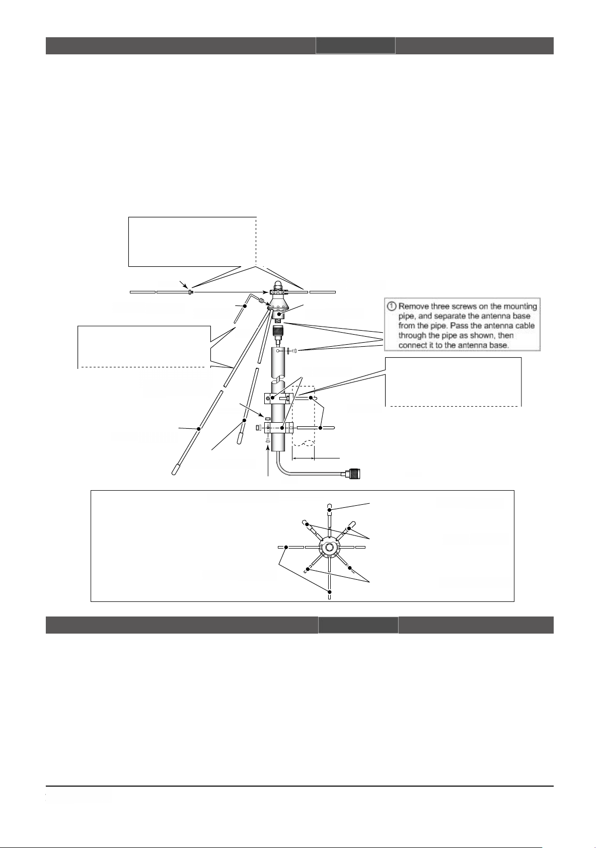
q Remove three screws on the mount-
ing pipe, and s ep arate t he ante nna
base from the pipe. Pass the antenna
cable through the pipe as shown, then
connect it to the antenna base.
w Attach th e cone elements (long a nd
sho r t) to the a nt en na base, and fi x
the element with the set screwU. See
the figure below for attaching order.
Antenna base
/アンテナベース
Allenwrench
/六角レンチ
Set
screw
/取付
ネジ
e Attach the disk elements (long and
short) to the antenna base through
the nuts (M4), and fix the element
with the nuts. See the figure below
for attaching order.
r A tt ac h the m ounting br acket to t he
moun ti ng pipe, th en f ix i t to a p ole
using with the V-bolts.
The pole diameter should be 25 to 50
mm (1 to 2 inch).
q Antenna base with bracket pipe ����������1
w Disk elements (long and short) �������� 4 each
e Nuts (M4; for disk elements) ������������8
r Cone elements (long and short) ������� 4 each
t Set screws ��������������������8
y Allen wrench �������������������1
u Mounting bracket �������������� 2 sets
i V-bolt sets (incl. spring washers and nuts) ��� 2 sets
o Screws (PH M5×15) ���������������2
!0 Nuts (M5) ��������������������2
!1 Antenna cable with type-N connectors (15
m; 4.9 ft) �� 1
Assembling the antenna/アンテナの組み立て
q
アンテナベース(ブラケットパイプ含む) ���������
w
ディスクエレメント(L、S) �������������� 各
e
ナット(M
r
コーンエレメント(L、S) ��������������� 各
t
取付ネジ(M
y
六角レンチ ����������������������
u
取付ブラケット ��������������������
i
Vボルトセット(Sワッシャ、ナット含む) ���������
o
ネジ(PH M
!0
����������������������
!1
同軸ケーブル(N型コネクタ付き:
4
;ディスクエレメント用) �����������8個
4×6
) �������������������8個
5×15
) �������������������2本
15
m) ����������1本
1
個
4
本
4
本
1
本
2
組
2
組
2
個
• Frequency coverage (unit: MHz):
Rx 100–3300
Tx 118–137, 144–148, 222–225, 430–450,
• Type of antenna : Omnidirectional Discone antenna
• Gain : 3 dBi (max.)
• Antenna connector : Type-N (50 Ω: nominal)
• Max. input power : 200 W
• Total antenna height : 936 mm (±10 mm); 3 ft (±
• Weight (approx.) : 970 g (±20 g); 2 lb 2 oz (±23⁄32 oz)
Specifications/電気仕様
902–928, 1240–1300, 2300–2450
13
⁄32 in)
(except antenna cable)
• Wind resistance : 50 m/sec.; 97.2 kt; 111.8 mph
All stated specifications are subject to change without notice or obligation.
受信
送信
※定格、外観、仕様などは、改良のため、予告なく変更することがあります。
周波数帯域(単位:MHz):
100~3300
118~137、144~148、222~225
430~450、902~928、1240~1300
2300~2450
型式 :無指向性ディスコーンアンテナ
3
アンテナゲイン :
アンテナコネクター形状:N型(
最大入力電力 :
全高 :
重量 :約
耐風速 :
dBi(最大)
50
Ω)
200
W(送信可能周波数帯域内に限る)
936
mm(±10mm)
970
g(±20g/同軸ケーブル除く)
50
m/sec.
、
、
 Loading...