

Page 1
INSTRUCTION MANUAL
HF AUTOMATIC TUNING ANTENNA
AH-740
* The “stand” in the photo is not
supplied with the tuning antenna.
Page 2

FOREWORD
EXPLICIT DEFINITIONS
Thank you for purchasing the AH-740 h f a u t o m a t i c t u n i n g
a n t e n n a .
The AH-740 is designed, primarily for use with Icom HF
transceivers.
Refer to your HF transceiver instruction manual for operation.
If you have any questions, contact your dealer.
IMPORTANT
READ ALL INSTRUCTIONS carefully and completely
before using the AH-740.
SAVE THIS INSTRUCTION MANUAL. This instruc-
tion manual contains important safety and installation instructions.
i
WORD DEFINITION
R DANGER!
R WARNING!
CAUTION Equipment damage may occur.
NOTE
Personal death, serious injury or an explosion may occur.
Personal injury, fire hazard or electric
shock may occur.
Recommended for optimum use. No risk
of personal injury, fire or electric shock.
FEATURES
Compact and light weight ❍
Fast tuning speed ❍
Covers 2.2 to 30 MHz range when using ❍
with the optional NVIS kit
Icom, Icom Inc. and the Icom logo are registered trademarks of Icom
Incorporated (Japan) in Japan, the United States, the United Kingdom, Germany, France, Spain, Russia and/or other countries.
Page 3

PRECAUTIONS
TABLE OF CONTENTS
RDANGER HIGH VOLTAGE! NEVER touch the antenna
terminal, ground terminal, antenna while transmitting.
RWARNING! NEVER transmit while installing the anten-
na. This may cause an electric shock.
NEVER use without a ground connection.
USE the ground terminal for ground connection.
DO NOT operate your HF transceiver without running the
vehicle’s engine. When the transceiver’s power is ON and the
vehicle’s engine is OFF, the vehicle’s battery will soon become exhausted.
DO NOT use the AH-740 in areas where the temperature is
below –40°C (–40ºF) or above +70°C (+158ºF).
RWARNING! At least two people are needed to unpack
the optional AH-5NV
element is tightly coiled and can spring open with a lot of
force. This could cause a serious injury or other damage.
n v i s k i t . Work in an open space as the
FOREWORD …………………………………………………………… i
IMPORTANT …………………………………………………………… i
EXPLICIT DEFINITIONS …………………………………………… i
FEATURES …………………………………………………………… i
PRECAUTIONS ……………………………………………………… ii
TABLE OF CONTENTS ……………………………………………… ii
SUPPLIED ACCESSORIES ………………………………………… iii
MISCELLANEOUS ITEMS …………………………………………… iii
1 SYSTEM INSTALLATION .........................................................1
Ground connection ■ …………………………………………… 1
Cabling ■ ………………………………………………………… 1
Coaxial cable ■ ………………………………………………… 1
About mounting base ■ ………………………………………… 1
2 INSTALLATIONS ......................................................................2
Typical installation scenarios ■ ……………………………… 2
Precautions when the optional AH-5NV is installed on a D
vehicle………………………………………………………… 3
Installation outline ■ …………………………………………… 4
Mounting ■ ……………………………………………………… 4
Cable connections ■ …………………………………………… 5
Optional AH-5NV ■ ……………………………………………… 6
3 SPECIFICATIONS AND OPTIONS ...........................................7
Specifications ■ ………………………………………………… 7
Control connector information D …………………………… 7
Options ■ ………………………………………………………… 7
ii
Page 4
SUPPLIED ACCESSORIES
qw
e
rty
!0
ui
o!1
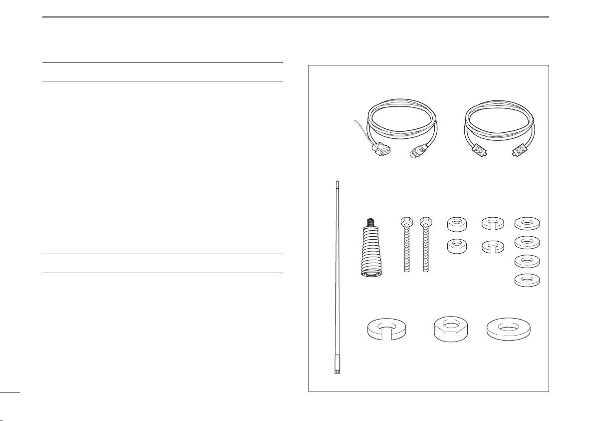
The following accessories are supplied with the antenna.
q Control cable (approximately 6 m; 19.7 ft) ...................... 1
w Coaxial cable (approximately 6 m; 19.7 ft) ...................... 1
e Whip antenna ................................................................. 1
r Antenna spring ............................................................... 1
t Bolts (M8) ....................................................................... 2
y Nuts (M8) ........................................................................ 2
u Spring washers (M8) ....................................................... 2
i Flat washers (M8) .......................................................... 4
o Spring washer (M16) ..................................................... 1
!0 Nut (M16) ...................................................................... 1
!1 Flat washer (M16) ......................................................... 1
MISCELLANEOUS ITEMS
The following items are additionally required for installation,
but is not supplied with the AH-740.
Purchase the item locally.
• Mounting base
• Rubber vulcanizing tape
• Electrical tape
iii
Page 5

SYSTEM INSTALLATION
1
Ground connection ■
It is absolutely essential that the antenna is connected to
an effective and stabile RF GROUND POINT— the vehicle
chassis. It is further recommended that body panels are also
bonded to the vehicle chassis. Make sure all contact points
are free of paint and ground to a shiny finish and protected
from rusting with conductive grease, before bolting the mounting stud and ground strap terminals.
Cabling ■
A coaxial cable and a control cable are supplied with the tuning antenna. A ground strap is provided on the base of the
tuning antenna to ensure a reliable connection with the vehicle’s metalwork. Connect the ground strap to both the chassis frame or the body metalwork, whenever possible. Avoid
feeding the antenna cables together with the engine ignition
cabling routes. Use a One-Point (Star) Station Ground for the
entire HF system where your transceiver is installed. Feed
both (B+ and B–) thick wires from the vehicle battery to the
transceiver location. Do not use the vehicle’s metalwork as a
replacement of the B– wire.
Use suitable noise filters for alternators. Ask your dealer for
details.
Coaxial cable ■
Insulate the lead-in cable of the AH-740 antenna terminal and
antenna element from other metal objects. To prevent interference, keep cables as far as possible from other antennas and
electronic equipment.
About mounting base ■
A mounting base for the AH-740 installation must be locally
prepared.
Select or fabricate a strong metal bracket for the antenna
plate, about 8–10 mm (0.31–0.39 inches) thick, and weld or
bolt it firmly to the vehicle chassis or other strong structure.
Ask your technical dealer or installer for suitable mounting
base details.
1
1
1
Page 6

2
Typical installation scenarios ■
INSTALLATIONS
Most recommended SUV installation scenarios use a Universal Gibbet Mounting System (front) or the Spare Wheel
Antenna Bracket (rear). Note the tuning antenna unit is kept
clear of the vehicle’s hood and other metal panels. Best communications in all directions is ensured.
Recommended installation options on a typical pickup vehicle
use a Universal Gibbet Mounting System (front) and a customer provided bracket (middle). Both methods provide effective communications in all directions.
Recommended installation options on a typical sedan vehicle
use a Universal Gibbet Mounting System for both front and
rear antenna locations. Note the tuning antenna unit is optimally raised above the trunk and hood of the vehicle.
NON-RECOMMENDED installation methods use a Universal
Gibbet Mounting System (both at the rear) shown on a typical minivan or 4WD vehicles. Note the entire Antenna Main
Assembly and partially Whip Section are OBSTRUCTED by
vehicle metal panels. Communications will be affected.
2
2
Page 7

INSTALLATIONS
2
For best communications, position the antenna as high as
possible. The Figure 1 shows the preferred option selection.
The Figure 2 shows an antenna installation that uses the optional AH-5NV, for best communications on the 30–300km
(18.6–186.5 miles) short ranges, and up to 1500 km (932
miles) medium ranges.
Figure 1
Figure 2
What is NVIS?
NVIS stands for Near Vertical Incidence Skywave.
The NVIS radio-wave propagation provides usable signals
between groundwave and skywave distances. (between 50
and 650 km; 30 and 400 miles) The radio waves from the
antenna travel upwards into the ionosphere, and then are
refracted back down in a circular area. The signals can be
received up to 650 km (400 miles) from the transmitting station. Refraction fails if the frequency is too high. The signal
strength is reduced if the frequency is too low, because of
absorption.
Precautions when the optional AH-5NV is in- D
stalled on a vehicle
RWARNING! The NVIS antenna element can swing a lot
while driving. Therefore, we strongly recommend that you remove the NVIS antenna while driving. Otherwise the antenna
element may swing excessively and interfere with your driving.
2
3
Page 8

INSTALLATIONS
AH-740
Antenna
spring
Whip
antenna
2
Installation outline ■
IMPORTANT!
The antenna is a critical element in any communication system. Correct installation is very important factor for achieving
the utmost in antenna system performance and operation of
your transceiver. We recommend that installation of the AH740 be carried out by qualified technicians only.
Attach a mounting base to a desired position on your ve- q
hicle.
• Purchase the mounting base locally.
Mount the AH-740 onto the mounting base. w
• Refer to “Mounting.”
Connect the control and coaxial cables between the trans- e
ceiver and the AH-740.
• Refer to “Cable connections.”
Connect the ground strap to the vehicle’s chassis. r
• Refer to “Cable connections.”
Attach the supplied antenna spring and whip onto the AH- t
740.
Mounting ■
RWARNING! Mount the AH-740 securely with the supplied
nuts and bolts. Otherwise, vibrations and shocks due to rough
terrain could loosen the antenna. It could fall, causing personal injury.
• For the greatest radiation effectiveness, position the antenna as high as possible.
• For human safety, mount the antenna at the front and opposite side of the driver's position, whenever possible.
- Refer to the pictorial installations and scenarios shown on the
pages 2 and 3.
• Make sure to allow enough clearance around the antenna
so that any antenna flexing will not damage the vehicle—
bear in mind that the Main Assembly can flex as much as 16
cm (0.63 inches), without damage.
• Make sure the antenna is as far from the vehicle’s vertical
and horizontal metal panels as possible.
• Mount the antenna on a mounting base with a 17 mm
(0.67 inches) hole for the M16×2 mm (M0.63×0.08 inches)
threaded mounting stud.
• Rotate the Main Assembly until the ground strap is directed
towards the vehicle body, and then firmly tighten the stud
nut.
• Use only the original hardware and proper tools.
4
4
Page 9

INSTALLATIONS
Rubber
vulcanizing
tape, then
electrical
tape.
Coaxial
cable
Control
cable
Ground
strap
Vehicle chassis or body
2
Cable connections ■
Connect the coaxial cable and the control cable to the AH- q
740.
• Insert the control cable connector into the antenna body socket,
then rotate the connector ring to lock it in place.
Wrap the antenna connector with rubber vulcanizing tape, w
and then wrap electrical tape* over the rubber vulcanizing
tape to secure waterproofing.
* The rubber vulcanizing tape and electrical tape are not supplied
with the AH-740. Purchase them locally.
Secure both the coaxial and control cables to protect the e
inside connections.
Connect the coaxial cable and the control cable to the
transceiver.
• Connect the coaxial cable to an appropriate antenna connector.
• Connect the control cable to the D-sub 9 pin type antenna tuner
control connector, or the 4 pin type connector when the optional
OPC-2321 is used.
• See the transceiver instruction manual for details. The antenna
tuner connections in the manual are the same as for the AH-
740.
Ground the transceiver, AH-740 and shield cable of the r
control cable to the ground terminal.
• Coaxial cable and control cable connections
• About the ground strap connection
2
5
5
Page 10

INSTALLATIONS
Set screws
(Use 2.6 mm; 1⁄10˝ allen wrench)
Socket bolt
(Use 10 mm; 13⁄32˝
allen wrench)
Use allen wrench
to tighten
(6 mm;
1
⁄4˝)
• Swivel magnet holder
Allen wrench (2.6 mm; 1⁄10˝)
Swivel magnet holder
NVIS antenna
Set screw
2
Optional AH-5NV ■
When using the AH-740 with the optional AH-5NV, install the
AH-5NV as follows.
6
6
6
Place the swivel magnet holder onto the vehicle, and at- q
tach the NVIS antenna element to the antenna spring of
the AH-740.
• Secure the antenna element by tighten the set screws.
Insert the antenna element into the swivel magnet holder, w
as shown below.
Tighten the set screw. e
Page 11

SPECIFICATIONS AND OPTIONS
KEY
START
13.8 V
Front view
GND
SHIELD
NC
3
Specifications ■
• Frequency coverage: 2.2–30 MHz (with NVIS kit)
2.5–30 MHz (with supplied whip)
• Power supply requirement:
13.8 V DC
transceiver)
• Current drain: Maximum 0.6 A
• Operating temperature range:
• Antenna connector: SO-239
• Maximum Input power: 125 W (PEP)
• Automatic tuning time: Approximately 2 to 3 seconds
• Automatic tuning accuracy:
SWR 1.5:1
• Dimensions : 238(H) × 145(W) × 160(D) mm
(projections not included) ; 9.4(H) × 5.7(W) × 6.3(D) inches
(except whip and antenna spring)
• Weight (approximately): 3.5 kg; 7.7 lb
All stated specifications are subject to change without notice
or obligation.
–40°C to +70°C; –40ºF to +158ºF
(new frequency)
0.15 seconds
memorized frequency)
multiples of 1⁄2λ)
(supplied from the HF
(typical; retuning to a
(after tuning, except for
Control connector information D
2
3
Options ■
• AH-5NV n v i s k i t
Approximately 4.5 m (14.8 ft) long antenna, covers 2.2 MHz through
30 MHz.
RWARNING! At least two people are needed to unpack the op-
tional AH-5NV n v i s k i t . Work in an open space as the element is
tightly coiled and can spring open with a lot of force. This could
cause a serious injury or other damage.
• OPC-2321 c o n t r o l c a b l e
Approximately 6 m (19.7 ft) long control cable for Icom's amateur
transceivers, that have a 4 pin type antenna tuner control connector.
Approved Icom optional equipment is designed for optimal performance when used with an Icom product.
Icom is not responsible for the destruction or damage to an Icom
product in the event the Icom product is used with equipment that is
not manufactured or approved by Icom.
7
Page 12

A-7088H-1EX
Printed in Japan
© 2013 Icom Inc.
1-1-32 Kamiminami, Hirano-ku, Osaka 547-0003, Japan
 Loading...