

Page 1
2.4 GHz DOWN CONVERTER
AG-2400
Thank you for purchasing this Icom product.
The AG-2400 is designed and built with Icom’s
superior technology and craftsmanship. With
proper care this product should provide you with
years of trouble-free operation.
IMPORTANT
READ THIS INSTRUCTION MANUAL
CAREFULLY before attempting to operating the AG-
2400.
SAVE THIS INSTRUCTION MANUAL—This
manual contains important safety and operating instructions for the AG-2400.
PRECAUTIONS
CAUTION! The coaxial cable between this down
converter unit and your transceiver should be clamped
to the antenna pole to prevent the down converter unit
from weighing down the preamplifier.
KEEP the unit away from TV or radio antennas to
prevent interference.
ï
FEATURES
❍ Down Converter for satellite (AO-40) in
S-mode operation
❍ Built-in Low Noise Amplifier (LNA)
Total NF value is less than 1.5 dB,
Conversion Gain is more than 25 dB
❍ Built-in Receiver-Suppression-Control Fil-
ter closes up the uplink and downlink
antennas. (1.8 feet at the minimum)
❍ Built-in the Receiving Protection Circuit
• The built-in circuit protector may not function correctly when the accidental transmission such as
continuous transmission is applied. Such transmission is out of the specified guarantee for accidental
transmission damage to the AG-2400.
❍ Waterproof, weather resistance and pre-
vention from rusting due to salt water.
❍ No power cable wiring is necessary.
EXPLICIT DEFINITIONS
WORD DEFINITION
Personal injury, fire hazard or electric
shock may occur.
Equipment damage may occur.
If disregarded, inconvenience only. No risk
of personal injury, fire or electric shock.
RWARNING
CAUTION
NOTE
SPECIFICATIONS
• Receive frequency : 2400–2402 MHz
• Out put frequency : 144–146 MHz
• Total gain : More than 25 dB
• Total NF value : Less than 1.5 dB
• Input/Output connector : Type-N
• Antenna impedance : 50 Ω
• Grounding : Negative grounding
• Power consumption : Approx. 200 mA
• Dimensions (Projections not included)
: 172(W)×69.5(H)×230(D) mm
:6
25
⁄32(W)×23⁄4(H)×91⁄16(D) in
• Weight (approx.) : 1.18 kg; 2.6 lb 41 oz
SUPPLIED ACCESSORIES
q U-bolts ………………………………………………2
w U-bolt plates …………………………………………2
e Washers (M6) ………………………………………4
r Spring washers (M6) ………………………………4
t Wing nuts (M6) ………………………………………4
y Hex head bolts (M6×50) ……………………………4
u Self-tapping screws (6×30 A0) ……………………4
• Instruction manual
w
q
e
r
t
y
u
CAUTION FOR INSTALLATION
AG-2400 is intended for professional installation only .
We are not responsible for any building breakage, any
damage resulting from a drop of the AG-2400 from a
high place or unstable site resulting in personal injury ,
nor any accident in any other cases. If the AG-2400
must be installed at such high place or unstable site,
be sure to consult an expert engineer.
Icom, Icom Inc. and the logo are registered trademarks of Icom
Incorporated (Japan) in the United States, the United Kingdom, Germany, France, Spain, Russia and/or other countries.
INSTRUCTION MANUAL
Page 2
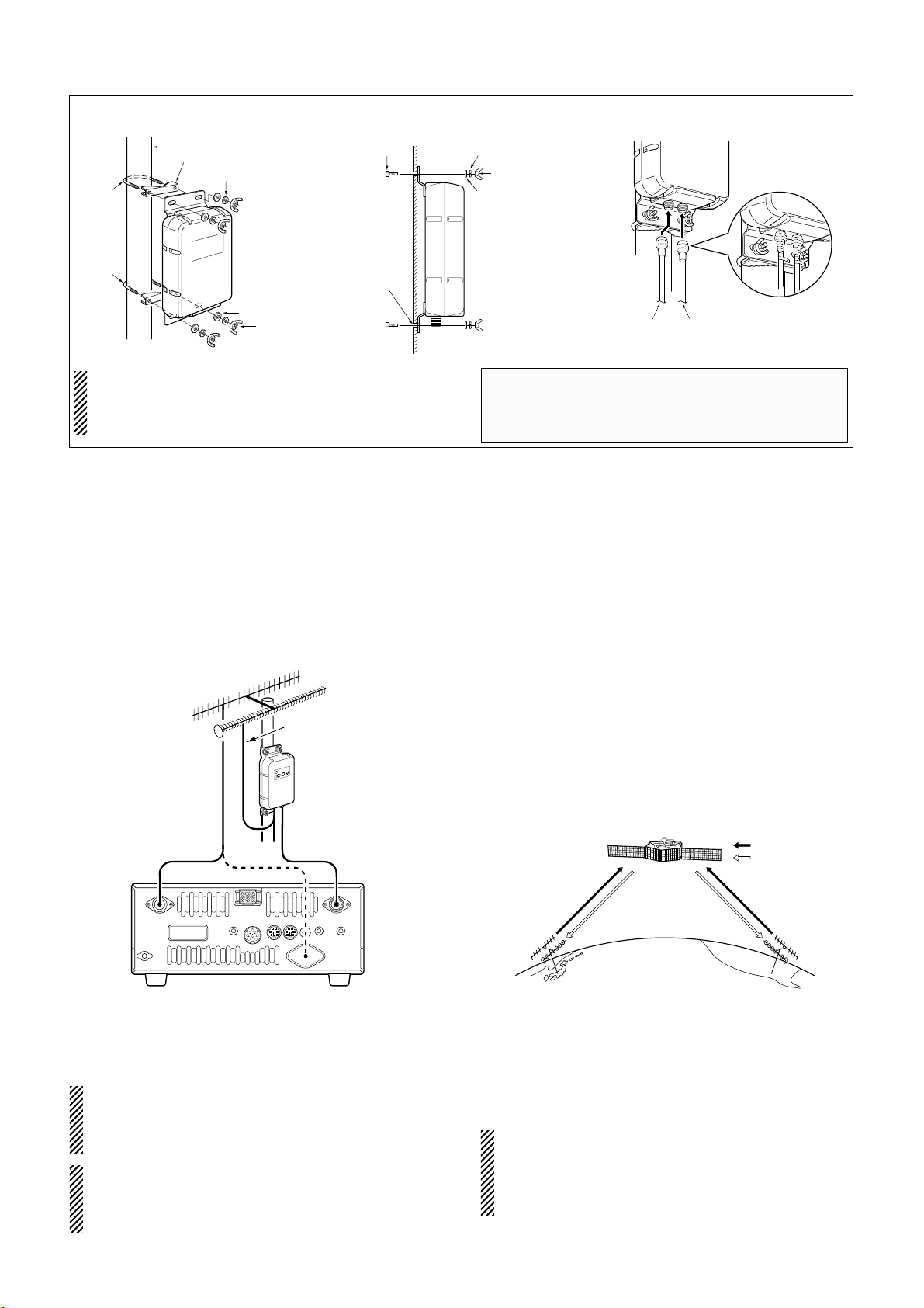
■ Connections
Satellite communications via the AO-40 can be made
when using the IC-910H satellite function mode and
the AG-2400.
For satellite communications, an antenna rotator which
adjusts the antenna direction (azimuth), and an elevation angle rotator which adjusts the angle above the horizon, are necessary .
See back page on how to operate.
ï Converting frequency with the AG-2400
• 2400.225–2400.475 MHz to 144.225–144.475 MHz
• 2401.210–2401.495 MHz to 145.210–145.495 MHz
NOTE: Turn the pre-amplifier controller for 144 MHz
ON during satellite operation with the AG-2400, because the external pre-amplifier control voltage is
used as the AG-2400’s main power.
CAUTION! NEVER transmit on the 144 MHz band.
The AG-2400 may be damaged. The built-in protector may not function correctly when accidental transmission such as continuous transmission is applied.
ï Before setting
Test to operate on the ground before installation is recommended.
q Connect AG-2400 and IC-910H. (See the figure at
left.)
w Turn the IC-910H power ON.
• Push [M/S] to set the 144 MHz as in the MAIN band.
e Push [SSB/CW] to select SSB or CW mode.
r Push [ATT•P.AMP] for 1 sec. to turn the AG-2400
power ON.
• When the AG-2400 functions correctly, the noise level
rise up.
ï Orbit information
Orbit information describes satellite location, wave angles, etc. This information may be available in ham
magazines or organization issues, such as from ARRL
or RSGB handbook, etc.
Use of satellite tracking software is also convenient.
ï AO-40
• Uplink frequency : 435.780–435.495 MHz
• Downlink frequency: 2400.225–2400.475 MHz (S1 BAND)
• Downlink frequency: 2401.210–2401.495 MHz (S2 BAND)
• Beacon frequency : 2400.338 MHz (S1 BAND)
2401.323 MHz (S2 BAND)
Confirm a satellite’s operating mode in advance
through documentation (magazines, etc.) or via appropriate satellite tracking software. In the wrong
mode, you cannot use the satellite even if you receive its beacon signal.
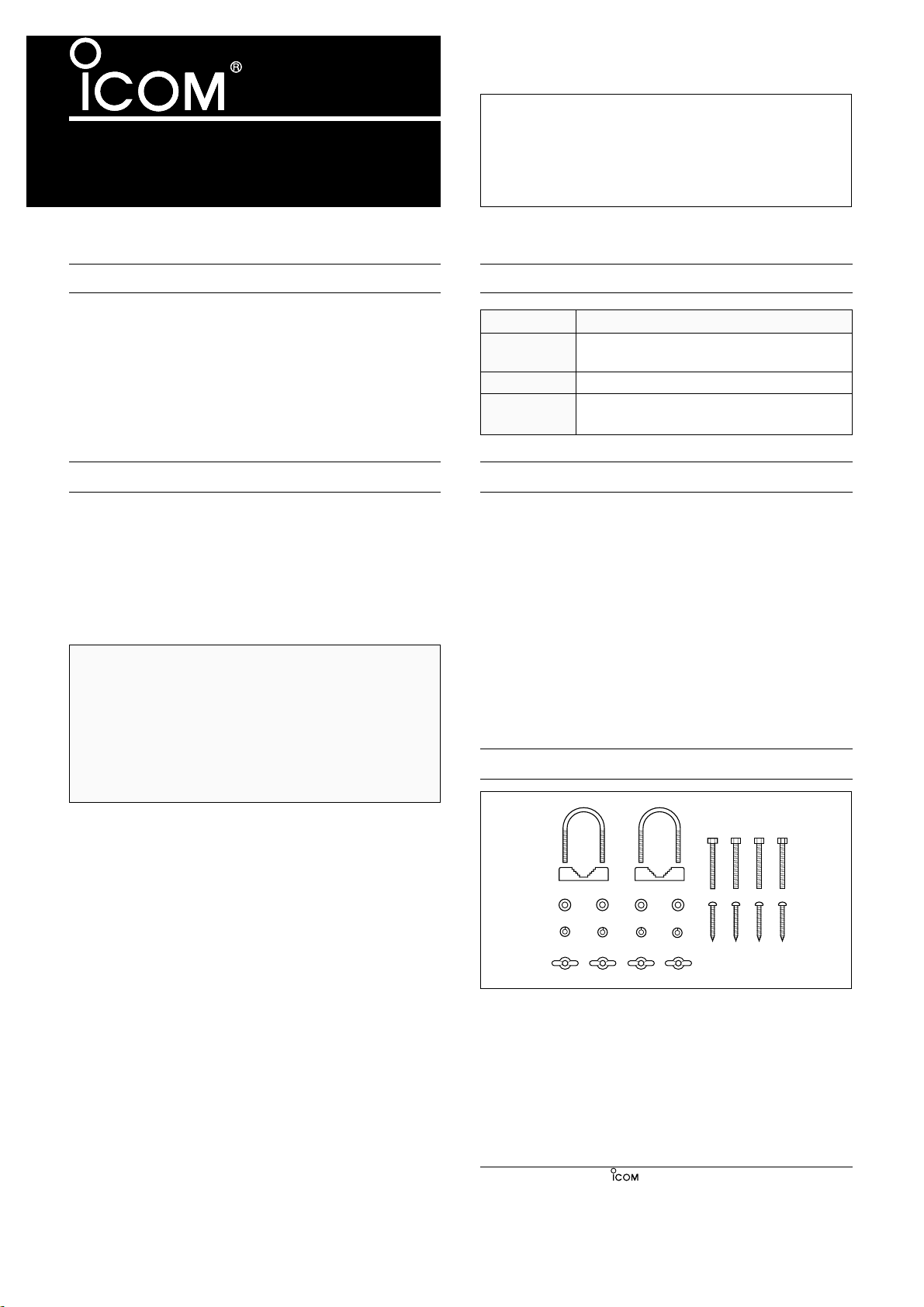
S-washer
Washer
U-bolt
U-bolt
Wing nut
Pole
AG-2400
Pole clamp
Washer
S-washer
Hex-Head
bolt
6.6–7 mm
Hole
AG-2400
Wing nut
AG-2400
To IC-910H
144MHz ANT connector
To 2400MHz
antenna
• Use the U-bolts
• Use the nuts • About waterproofing
The AG-2400 can also be installed with self-tapping
screws.
Tighten the U-bolts, Wing nuts, etc. about 2 weeks
after initial installation.
NOTE: Cover the type-N connector with self valcanizing tape to avoid water seeping into the unit. Binding the type-N connector with self valcanizing tape
increases the waterproofing of the connection mold.
■ Installation
IC-910H
AG-2400
To 144MHz
ANT connector
To 430MHz
ANT connector
2400MHz band
144MHz band
430MHz
band
1200MHz band
* 1200 MHz band operation also available with AO-40.
Uplink
Downlink
2400 MHz
band
2400 MHz
band
435 MHz
band
435 MHz
band
AO-40
• Connect AG-2400 and IC-910H
Page 3

■ Activating the satellite mode
Operating frequencies in satellite mode can be set both
before and after activating the satellite mode. Normal
and reverse tracking are available.
ï Transferring the VFO frequency to the satellite
VFO.
q Set the downlink frequency (receive) in the MAIN
band.
w Set the uplink frequency (transmit) in the SUB band.
e Push [SATELLITE] for 1 sec. to transfer the fre-
quencies, set in steps q and w, into the satellite
VFO.
• Satellite mode is automatically selected after transferring.
• “SATL” indicator with either “NOR” or “REV” indi-
cator appears.
• VFO and memory mode indication are displayed in
the SUB band (lower area) during satellite mode.
■ Setting the satellite VFO
q Push [SATELLITE] to enter the satellite mode.
• “SATL” indicator with either “NOR” or “REV” indicator ap-
pears.
w Push [V/M 1] to toggle satellite VFO and memory
mode.
• VFO or memory mode indication is displayed in the SUB
band (lower area).
e Push [SCAN . M ] to enable the downlink frequency
tuning.
• Uplink frequency indication disappears.
• Rotate the tuning dial to set the downlink frequency and
push [SSB/CW] to select the operating mode.
• Push [SCAN . M ] again after the tuning.
r Push [SWP0 S ] to enable the uplink frequency tuning.
• Downlink frequency indication disappears.
• Push [SWP 0 S ] again after the tuning.
NOTE: To select the operating mode for the uplink,
push [SUB] to enable the SUB band access.
[SATELLITE]
for 1 sec.
[F-INP ENT]
USBUSB
MEMO
L
SB
SAT
L
RE
V
S 1 357
9 2020
4040
60dB60dB
60dB
S
1
3 5
7920
40
P.AMP
USBUSB
MEMO
L
SB
SAT
L
RE
V
S 1 357
9 2020
4040
60dB60dB
60dB
S
1
3 5
7920
40
P.AMP
■ Tracking selection
Push [F-INP ENT ] for 1 sec. to switch between normal and reverse tracking.
ï Normal tracking
Both downlink and uplink frequencies increase or decrease in the same step simultaneously by tuning dial
rotation.
ï Reverse tracking
The downlink frequency follows the tuning dial rotation,
however, the uplink frequency changes in the reverse
direction to the tuning dial rotation in the same step.
■ Preparation
q Decide on a usable satellite.
w Confirm the approximate location of the satellite and
operating mode (e.g. “B,” “J,” etc.) through documentation (magazine, etc.) or via appropriate satellite tracking software.
e Set the antenna direction for the desired satellite.
r Select satellite mode on the transceiver.
• Push [SATELLITE].
• Push [F-INP ENT ] for 1 sec. to select track-
ing mode if desired.
t Select operating mode.
y Set the downlink frequency (MAIN band) to the bea-
con frequency.
• Refer to a ham magazine or book for detailed information.
• Adjust the antenna direction so that the S-meter shows
to its strongest level.
• The S-meter level should be noted for transmit power adjustment during a loop test.
NOR REV
USB
20
40
60dB
USB
20
40
60dB
Satellite
Downlink Uplink
(MAIN band) (SUB band)
Reverse tracking type USB (or CW) LSB (or CW)
Normal tracking type USB (or CW) USB (or CW)
NOR REV
S
1
NOR
SAT
RE
USB
3 5
L
V
S 1 357
P.AMP
7920
L
9 20
60dB
40
SB
40
MEMO
60dB
Satellite mode indication
Varies simultaneously
USB
Downlink (receive) frequency
P.AMP
3 5
S
7920
1
NOR
SAT
L
RE
V
S 1 357
Satellite mode indication
L
9 20
60dB
40
SB
40
MEMO
60dB
Uplink (transmit) frequency
Page 4

1-1-32 Kamiminami, Hirano-ku, Osaka 547-0003 Japan
Count on us!
A-6150H-1EX Printed in Japan
u Perform a loop test.
• Set the downlink frequency (MAIN band) to a vacant frequency within the satellite’s coverage.
• Push [SWP 0 S ] then, set the uplink frequency (SUB
band) while transmitting a single tone such as a whistle
to find your downlink signal and monitor your own signal
correctly. Push [SWP0 S ] after setting.
NOTE: To avoid excessive power, set the output
power so that the downlink signal strength is lower
than the beacon’s strength.
i Set the desired frequency to begin your satellite
communications.
• Both the downlink and uplink frequencies are changed
simultaneously.
o When your downlink audio drifts (Doppler effect),
push [SWP 0 S ] then rotate the tuning dial to adjust
the uplink frequency (SUB band) only.
Push [SWP 0 S ] again after setting.
• When a particular station’s audio is off frequency, use the
RIT function (push [RIT])
!0 To exit the satellite operation, push [SATELLITE].
CONVENIENT: As the transceiver has 10 satellite
memory channels, once set, desired satellite frequencies can be recalled instantly.
NOTE: As the downlink (MAIN band) signal is applied to the SUB band unit receiver circuit in satellite mode, an optional FL-133
CW NARROW FILTER
is
necessary to operate CW-N mode.
■ Satellite operation
When your own signal can be received with a loop test,
satellite communication can be performed.
q Rotate the tuning dial to re-tune the uplink frequency
after pushing [SWP 0 S ], when shifting a frequency
with the Doppler effect.
• The downlink frequency readout (MAIN band) disappears.
USBUSB
MEMO
L
SB
SAT
L
RE
V
S 1 357
9 2020
4040
60dB60dB
60dB
S
1
3 5
7920
40
P.AMP
USBUSB
MEMO
L
SB
SAT
L
RE
V
S 1 357
9 2020
4040
60dB60dB
60dB
S
1
3 5
7920
40
P.AMP
w Rotate the tuning dial to re-tune the downlink fre-
quency after pushing [SCAN . M ], when the operating station’s signal frequency is shifted.
• RIT function can also be used for downlink frequency
tuning within ±1 kHz range.
■ Satellite memory
The AG-2400 has 10 satellite memory channels to
memorize both uplink and downlink frequencies and
operating modes, etc.
ï Satellite memory selection
q Push [SATELLITE] to enter the satellite mode.
w Push [V/M 1] to select satellite memory mode.
• “MEMO” indicator and memory channel number are displayed beside the uplink frequency (SUB band) indication.
• Push [V/M 1] again to select satellite VFO.
e Push [DN▼] or [UP▲] to select the desired satellite
mode memory channel.
• The channels 00-09 are selectable.
• By pushing and holding either switch, the satellite mem-
ory channel changes continuously.
ï Satellite memory programming
q Select the desired satellite memory channel.
• Push [SATELLITE] to enter the satellite mode.
• Push [V/M 1] to select satellite VFO mode.
• Push [DN▼] or [UP▲] to select the desired satellite
mode memory channel.
w Set the desired downlink frequency to the MAIN
band and uplink frequency to the SUB band, as well
as operating mode.
• Push [Scan . M ] for downlink tuning, push [SWP 0 S ]
for uplink frequency tuning.
• Push [SUB] before the operating mode selection when
selecting operating mode for the uplink.
e Push [MW 4] for 1 sec. to program the set contents
to the satellite memory channel.
• 3 beep tones sound.
NOTE:Tracking selection, normal or reverse, is not
programmed in the satellite memory channels.
USBUSB
MEMO
L
SB
SAT
L
RE
V
S 1 357
9 2020
4040
60dB60dB
60dB
S
1
3 5
7920
40
P.AMP
Satellite memory
indication
USBUSB
MEMO
L
SB
SAT
L
RE
V
S 1 357
9 2020
4040
60dB60dB
60dB
S
1
3 5
7920
40
P.AMP
Select the desired
satellite memory
 Loading...