

Page 1
ICOM® 200/201/241
Page 2

Page 3

About this manual
ICOM-200 / 201
ICOM-241
Advice and support
Register
1
2
3
4
5
Page 4

Copyright © by Wilke Technology GmbH
Krefelder Str. 147
52070 Aachen / Germany
manual version 1.4
This manual, together with the hardware and software which it
describes, is copyrighted and may not be in any way copied,
translated or redered in any other form without the express
written consent of Wilke Technology GmbH.
Note The editors, translators and authors of this publication have
taken great care with the texts, illustrations and programs.
Nevertheless, errors cannot be completely excluded. Wilke
Technology thus assumes no warranty, legal responsibility or
liability for consequences resulting from incorrect information.
Should any errors be discovered in this publication, or in the
software, we welcome any comments and suggestions.
The information in this manual should not be regarded as a
warranty of certain product properties or features, and is subject
to changes in the interests of technical improvement.
All rights reserved.
Page 5

Contents
Contents
1 About this manual 1-1
Typographic conventions and symbols 1-2
2 ICOM-200 / 201 2-1
Versions 2-1
Differences between ICOM-200 and ICOM-201 2-1
First steps 2-2
Power supply 2-2
PC mode 2-2
RUN mode 2-3
Program download 2-3
SLEEP mode 2-4
Keyboard 2-6
LC display 2-8
Serial Interface 2-9
RS232 2-9
RS485 2-10
Opto inputs 2-11
Power outputs 2-13
Analog inputs 2-15
Analog inputs 2-15
Configuration 0...5V 2-16
Configuration 0…10V 2-17
Configuration 0...20mA 2-17
Setting the amplification 2-18
MF-2 Keyboard 2-20
TINY-Tiger® Pins 2-24
Pin layout 37-ch. D-Sub connector 2-24
Technical data 2-25
3 ICOM-241 3-1
First steps 3-2
Power supply 3-2
PC-Mode 3-2
RUN mode 3-3
Program download 3-3
Wilke Technology GmbH • 0241/918900 • http://www.wilke.de/ • support@wilke.de i
Page 6

Contents
Opto inputs 3-4
Power outputs 3-6
Serial interface 3-7
RS232 3-7
RS 485 3-8
Analog inputs 3-11
Pin layout 25-pin D-Sub connector 3-14
Technical data 3-15
ICOM 241 – 24V 3-16
Connection to PC 3-17
Technical data 3-17
4 Hints and help 4-1
BASIC-Tiger® Service Hotline: 4-1
5 Register 5-1
.
Wilke Technology GmbH • 0241/918900 • http://www.wilke.de/ • support@wilke.de
ii
Page 7

General
1 About this manual
This manual does introduce you into the control of the ICOM industry
computer family for a fast and easy use.
1
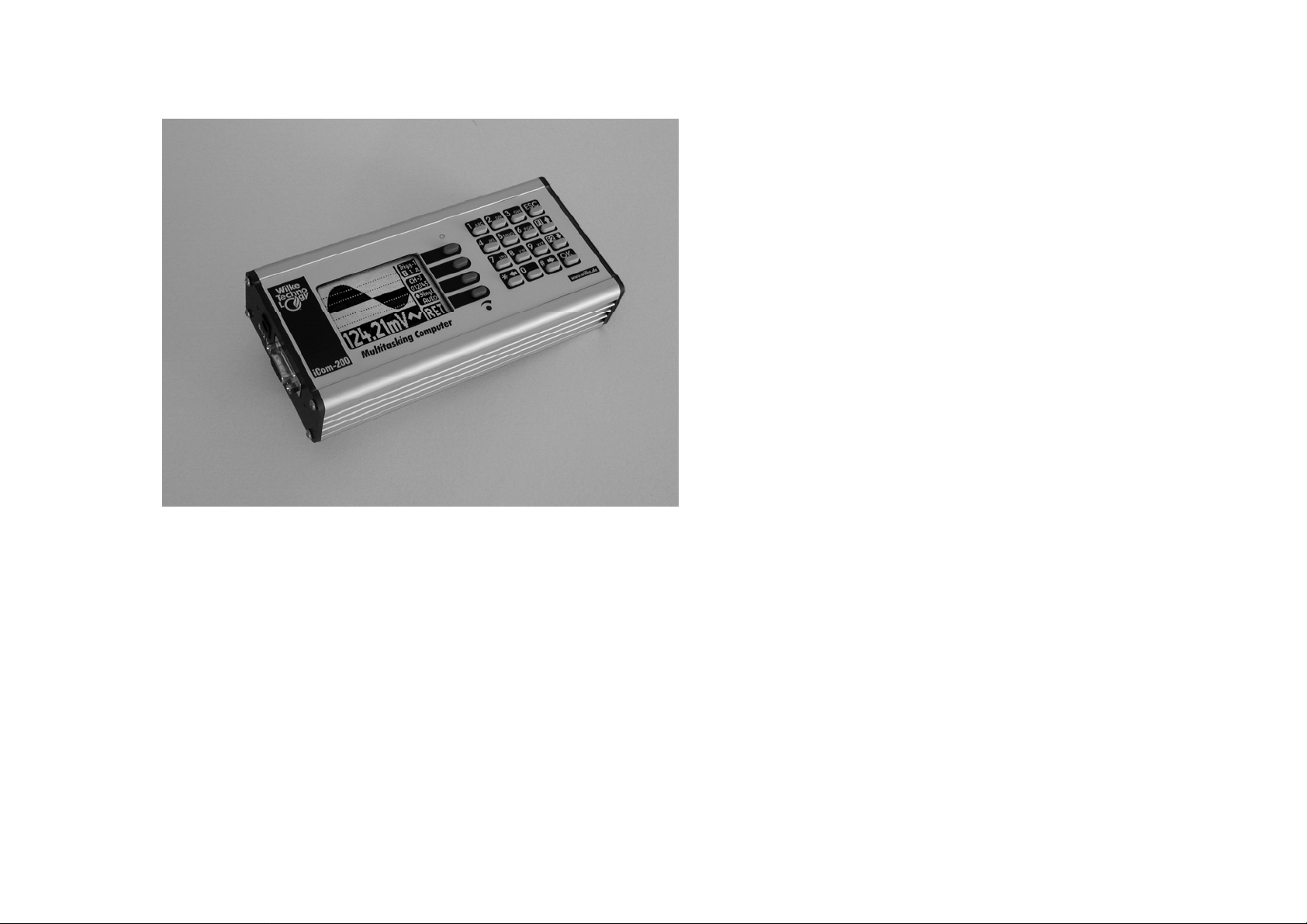
The ICOM industry computer family combines the performance of
BASIC/TINY-Tiger
elegant aluminum chassis. For programming the ICOM industry
computers a BASIC-Tiger
This manual only describes the usage of the ICOM industry computers.
You can read about the progamming of Tiny-Tigers
®
user manuals.
Tiger
®
Computers with steadily needed I/O peripherals in an
®
development system is needed.
®
in the BASIC/TINY-
Wilke Technology GmbH • 0241/918900 • http://www.wilke.de/ • support@wilke.de 1-1
Page 8
ICOM-manual
1
Typographic conventions and symbols
Following fonts and symbols are used for fast identification of important
informations:
Element
KEY
Program listing
Instruction
Variable
[ ]
Meaning
Key description, e.g. RETURN
Tiger-BASIC® program listing
Tiger-BASIC® instruction
Variables or constants you have to enter
according to your application.
Elements which can be entered optional.
Important remark: Please note!
!
Tip
Tipps and hints simplifying your work.
Wilke Technology GmbH • 0241/918900 • http://www.wilke.de/ • support@wilke.de
1-2
Page 9
ICOM-200 / 201
2 ICOM-200 / 201
Versions
This manual describes the ICOM200 and ICOM201 til version V1.3. Newer
versions are described in separate data sheets. At ICOM versions V1.4 or
newer, the version number is printed on the right hand side of the device.
Differences between ICOM-200 and ICOM-201
The ICOM-201 is a special version of the ICOM-200. The following decription
shows where the differences between the ICOM-200 and ICOM-201 are.
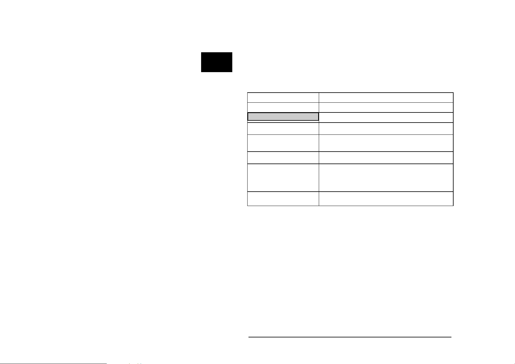
Feature ICOM-200 ICOM 201
Graphic LCD
20 key matrix keyboard
Serial interfaces
RS232 / RS485
MF2 keyboard
connector
Eight opto inputs
Four analog inputs
Eight power outputs
Battery backup
Sleep function Optional Optional
• -
• -
• •
• •
• •
• •
• •
• •
2
Note: The sleep function is available if the ICOM contains a TINY-Tiger® with
real time clock. It is not available, if internally e.g. a TINY-Tiger® TNN-R/4 is
used.
Wilke Technology GmbH • 0241/918900 • http://www.wilke.de/ • support@wilke.de 2-1
Page 10
2
ICOM-manual
First steps
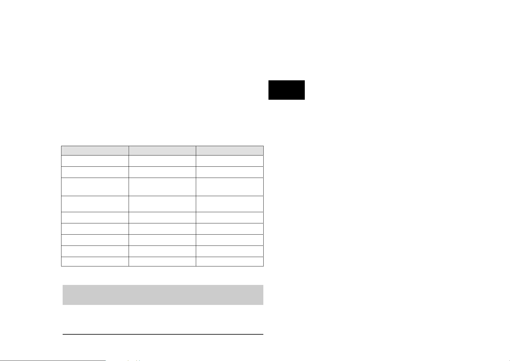
Power supply
The ICOM-200/201 uses a power supply with 8-12 VDC, 1A. Minus is placed
on the pin of the power supply connector. The current consumption is,
depending on the application, up to 400mA.
PC mode
After a reset or power-down the Tiny-Tiger® inside the ICOM-200/201 is
testing if the PC mode pin is „low“. In this case, the ICOM switches to PC
mode/Debug mode. Is the pin „high“, the ICOM starts in run mode. The time
between power-on and first activity on the I/O pins is approx. 230 msec.
To set the ICOM-200/201 to PC mode, a reset or power-down is needed.
Setting the DIP switch to PC mode while in run mode is not sufficient.
Wilke Technology GmbH • 0241/918900 • http://www.wilke.de/ • support@wilke.de
2-2
Page 11

ICOM-200 / 201
RUN mode
If the DIP-switch “PC/Run” is in position “Run”, the program in the ICOM200/201 is executed immediately after a reset. Debugging is not possible in
this mode.
Program download
A program created with the Tiger software is downloaded into ICOM-200/201
through the 9-pin Sub-D connector. To download the following has to be done:
Connect a power supply 8-12 V DC (Polarity: Inner contact = minus,
outer contact = plus)
Connect ICOM-200/201 and PC with 9-pin D-Sub cable
Set DIP switch of ICOM-200/201 to PC mode
Set the reset DIP switch to „Reset“ and back to original position
Start download at the PC.
Serial port 1 / Download DB-9 plug
TXD 2
RXD 3
GND 5
2
Wilke Technology GmbH • 0241/918900 • http://www.wilke.de/ • support@wilke.de 2-3
Page 12
2
ICOM-manual
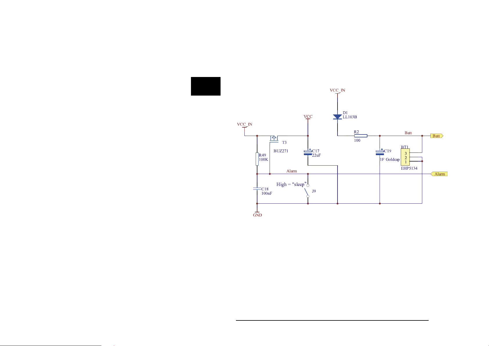
SLEEP mode
The ICOM-200/201 can be put into sleep mode if the Tiny-Tiger® inside has a
real time clock. In sleep mode the power consumption of the ICOM-200/201 is
descreased significantly to just approx. 25mA. While in sleep mode, no BASIC
program is executed by the ICOM-200/201.
Sleep circuit
®
The internal clock and SRAM of the Tiny-Tiger
Goldcap. The power consumption of clock and SRAM is approx. 70µA, with a
fully loaded Goldcap this is enough for about 3 hours.
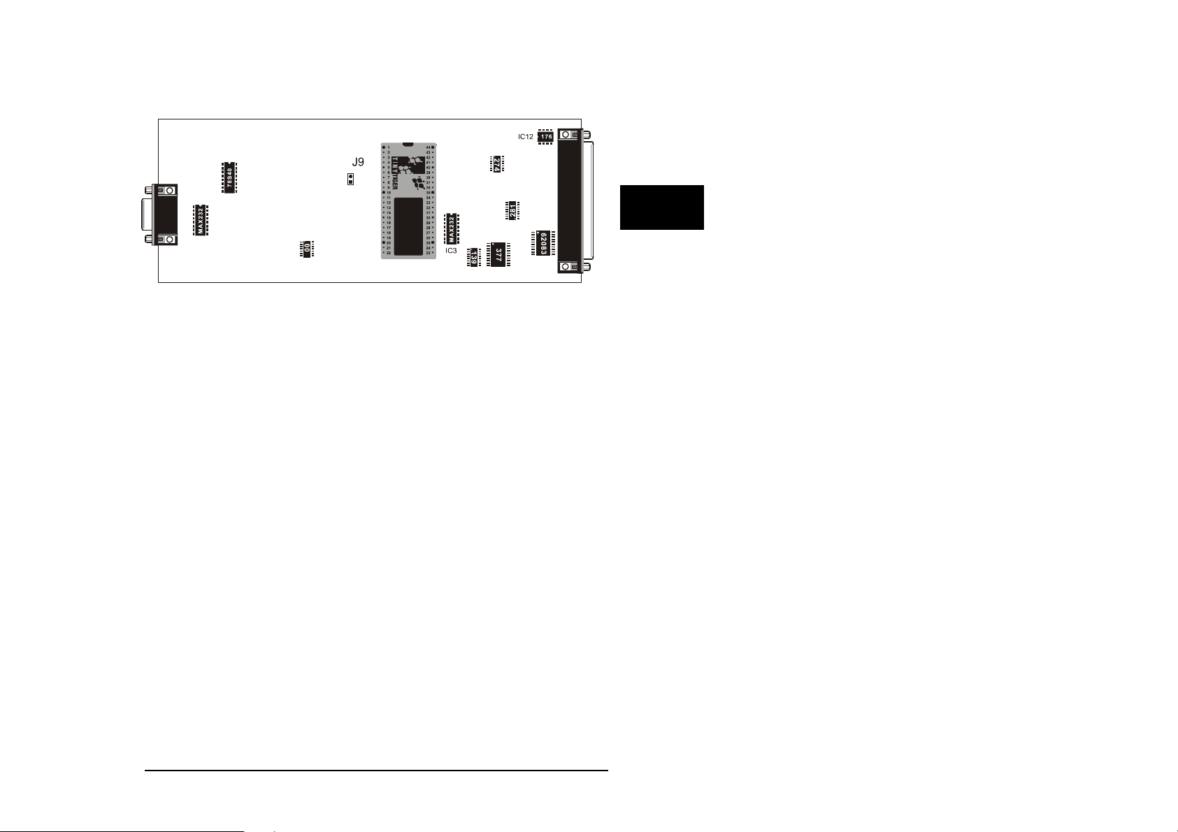
To use the SLEEP mode of the ICOM-200/201 Jumper J9, which is located
under the LC display, has to be drawn. On delivery the jumper is inserted, so
SLEEP mode is disabled.
Wilke Technology GmbH • 0241/918900 • http://www.wilke.de/ • support@wilke.de
2-4
are buffered through a
Page 13
ICOM-200 / 201
To put the ICOM-200/201 into sleep mode, the alarm time for the Tiny-Tiger
clock has to be set. Following that the ICOM-200/201 falls into sleep mode
and wakes up again at alarm time. More detailled information on how to set
the alarm time can be found in the BASIC-Tiger
If jumper J9 has been drawn and the Goldcap is unloaded, it takes about
30 seconds from connecting the power supply before the ICOM-200/201
switches on.
®
„Device driver“ manual.
®
2
Wilke Technology GmbH • 0241/918900 • http://www.wilke.de/ • support@wilke.de 2-5
Page 14
2
ICOM-manual
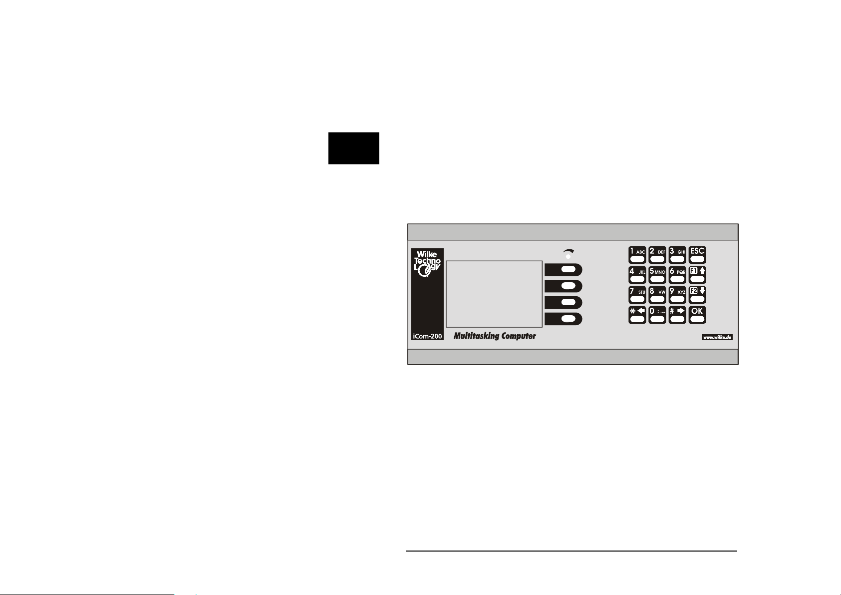
Keyboard
The ICOM-200 has a 20 key matrix keyboard. The keyboard is devided into
two blocks. The first block has four vertically arranged keys placed directly on
the right side of the LC display. Those keys can e.g. be assigned to a menu
on the LC display. The second block consists of 16 labeled keys.
Reading the keyboard is done with the device driver „LCD1.TDD“. The
following example scans the keyboard and gives back a numeric code for the
pressed key. Additionally a character can be assigned to the numeric code.
Read the „Device driver“ manual of the BASIC-Tiger
®
on how it is done.
With a physical offset of –10h the keyboard culumns are at the addresses 19h
to 27h. In order to scan the keyboard, the following settings have to be
implemented into the program.
USER_EPORT LASTLADR, 10h
USER_EPORT PHYSOFFS, 0F
Wilke Technology GmbH • 0241/918900 • http://www.wilke.de/ • support@wilke.de
2-6
0h
Page 15
ICOM-200 / 201
'-------------------------------------------------------------------'----- ICOM_KEYB.TIG
'--------------------------------------------------------------------
#define keyb 20 ' keyboard device nummer
#include define_a.inc
user_var_strict
TASK Main
word x,n,i
string a$
user_eport lastladr,10h
user_eport physoffs, 0f0h
Dir_port 8,0
INSTALL DEVICE #lcd,"LCD2.TDD",0,0,0EEH,1,150,11H' LCD-1=128x64, 150
KB/s
Install device #keyb, "LCD1.tdd", 0, 0, 0, 0, 0, 0, 80h, 8
print #keyb,& ' Definiert alle Scan-Spalten
"<1BH>D<16><1><1><1><0><0><0><0>& ' als Tastaturtasten
<0><0><0><0><0><0><0><0><0><0F0H>";
print #keyb,&
"<1Bh>k<18h><19h><1ah><1bh><1ch>& ' Legt die Tastaturadresse fest
<1dh><1eh><1fh><20h><21h><22h>&
<23h><24h><25h><26h><27h><0f0h>";
keys:
USING "UD<2><1> 0.0.0.0.2UH<2><2> 0.0.0.0.2" ' Format-String
FOR X=0 TO 0 STEP 0 ' Endlosschleife
FOR N=0 TO 0 STEP 0 ' Endlosschleife bis N=1(GET!)
RELEASE_TASK ' Rest der Task-Zeit freigeben
GET #keyb, #0, #1, 1, N ' N=Zeichen in Tastatur-Buffer
NEXT ' Ende Endlosschleife
GET #keyb, 1, A$ ' Tastatur-Buffer auslesen
PRINT #lcd, "<2><10>Key-No.="; ' Ausgabe auf LC-Display
PRINT USING #1, ASC(A$);"($";ASC(A$);")" ' zeige Tasten-Nr
NEXT
goto keys
end
2
Wilke Technology GmbH • 0241/918900 • http://www.wilke.de/ • support@wilke.de 2-7
Page 16

ICOM-manual
LC display
The ICOM-200 has a graphic LC display with a resolution of 128 x 64 pixel.
There’s a special device driver to control this display. By using this device
driver it is possible to control the LC display with simple BASIC commands.
2
Detailled information about usage of this device driver „LCD-6963.TDD“ is part
of the „Device driver“ manual of the BASIC-Tiger
®
.
The LC display has LED backlight. The backlight’s power consumption is
approx. 250mA. Power supply is 5V. To save energy backlight can be turned
off by software. For this Tiger pin P86 is used. Setting the pin to „1“ activates
the backlight, when set to „0“ backlight is off.
'-------------------------------------------------------------------'----- ICOM_DISPLAY_ON_OFF.TIG
'--------------------------------------------------------------------
#define display_off 0 ' LCD ausschalten mit P86
#define display_on 255 ' LCD anschalten mit P86
#include define_a.inc
user_var_strict
TASK Main
Dir_port 8,0
INSTALL DEVICE #lcd,"LCD2.TDD",0,0,0EEH,1,150,11H' LCD-1=128x64, 150
KB/s
print #lcd, "start"
wait_duration 2000
out 8,mask(6),display_off ' Display ausschalten
wait duration 2500 ' 2,5 sec warten
out 8,mask (6),display_on ' Display einschalten
print #lcd, "OK"
End
Wilke Technology GmbH • 0241/918900 • http://www.wilke.de/ • support@wilke.de
2-8
Page 17
ICOM-200 / 201
Serial Interface
As a standard the ICOM-200 and ICOM-201 have two serial interfaces. From
these the port Ser0 can by choice be configured as RS232 or RS485
interface. The port Ser1 always is a RS232 interface. In PC mode this port is
used for downloading the program into the ICOM 200/201. In Run mode it can
be used as a usual RS232 interface.
Detailled information about the serial interfaces can be read after in the
BASIC-Tiger
RS232
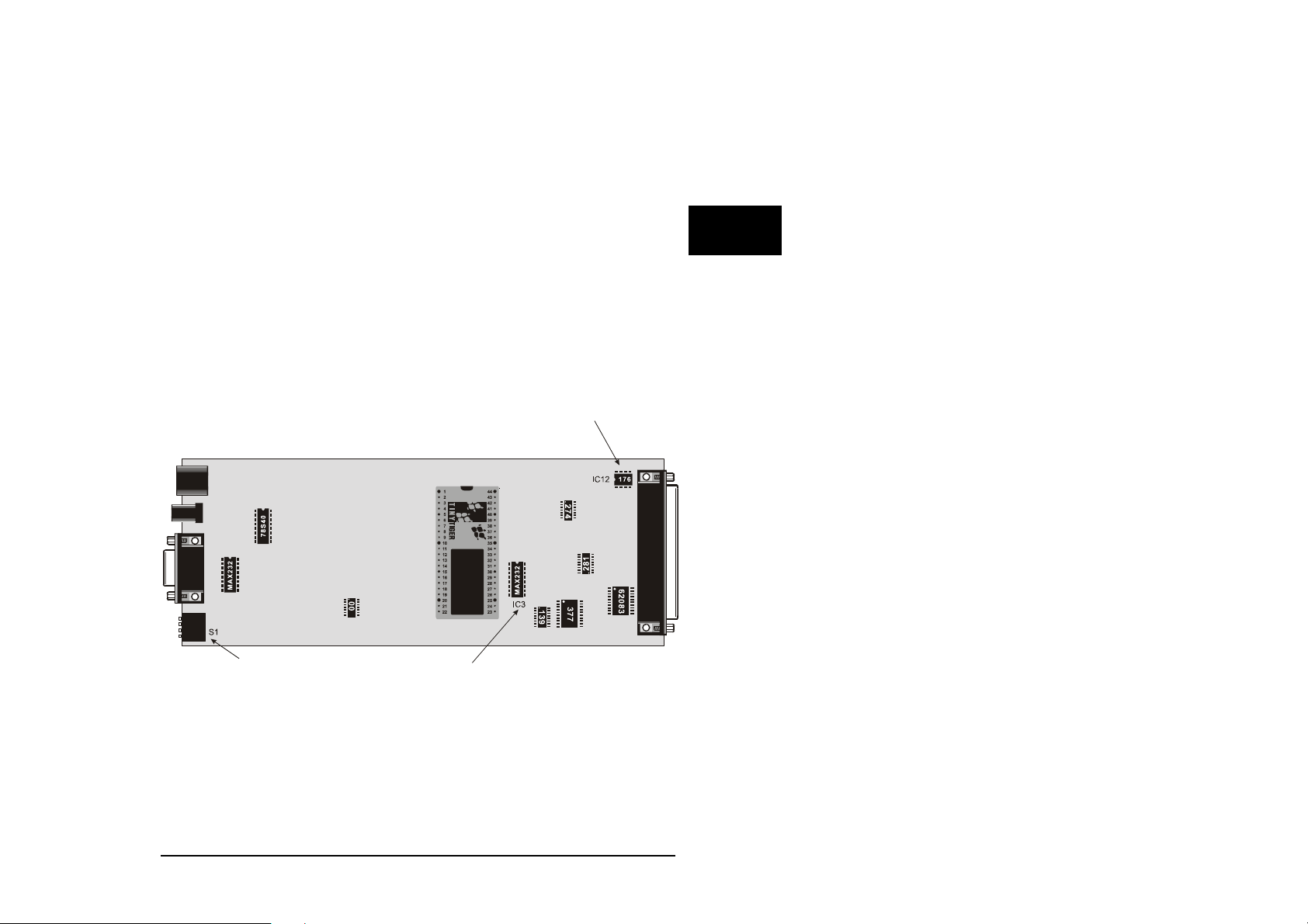
Serial port 0 can be configured as RS232 interface with three easy steps:
Remove IC12 from its socket
Please IC3 (MAX232) into the appropriate socket
Set the 4-channel DIP switch S1 to RS232.
®
„Device driver“ manual.
2
Attention: Never place IC3 and IC12 at the same time, as this could
lead to destruction of port 0 !!!
Wilke Technology GmbH • 0241/918900 • http://www.wilke.de/ • support@wilke.de 2-9
Page 18
2
ICOM-manual
The pins of serial port 0 are located on the DB-37 connector:
RS232 DB-37
TXD0 (Output) 16
RXD0 (Input) 17
RTS0 36
CTS0 35
RS485
The configuration of port 0 as RS485 interface is done by removing the IC3
(MAX232) and placing the IC12 (SN75176) into the 8-channel DIL socket. The
DIP switch on the left side plate of the ICOM-200/201 has to be set to RS485.
Removing or placing the ICs is only allowed without power supply.
Never place both ICs at the same time, this could lead to the destruction
of the ICOM-200/201.
RS485 DB37
TXD0 (A) 16
RXD0 (B) 17
Layout of DB37 connector (RS485)
Wilke Technology GmbH • 0241/918900 • http://www.wilke.de/ • support@wilke.de
2-10
Page 19

ICOM-200 / 201
Opto inputs
The ICOM-200/201 has eight optocoupler inputs suited for an input voltage
range of 5...12 VDC. To use higher input voltages, as 24V for example, an
additional serial resistor in the input line is used. The resistor value is selected
in accordance to 4...50mA input current needed for the logical “1” level.
The internal resistance is 680 Ohm / 0,25 W. If now another input voltage is
needed, the totally required resistance can be calculated with the following
formula:
2
= (UE-1,3V)/I
R
ges
I
R
Example:
Is e.g. an input voltage of 24 V with a current of 10 mA wanted, you get
from the above formula R
680 Ohm resistor has be replaced with a 2200 Ohm resistor (rounded to
norm value), or a resistor of 1500 Ohm has to be connected in series.
The optocoupled inputs are realized as extended inputs of the Tiny Tiger.
They can be accessed under logical port address 11h (physical 1).
Both USER_EPORT instructions in the sample program are urgent.
D
Optocoupler pin DB37 socket
Opto In0 6
Opto In1 25
Opto In2 7
Opto In3 26
Opto In4 8
Opto In5 27
Opto In6 9
Opto In7 28
GND 10
UE = Input voltage
= Current into the optocoupler
D
= Total resistance
ges
= 2270 Ohm. This means either the internal
ges
Wilke Technology GmbH • 0241/918900 • http://www.wilke.de/ • support@wilke.de 2-11
Page 20

2
ICOM-manual
'-------------------------------------------------------------------'----- ICOM200_OPTOIN.TIG
'--------------------------------------------------------------------
#include define_a.inc
user_var_strict
TASK Main
BYTE wert
USER_EPORT lastladr,10h
USER_EPORT physoffs, 0f0h
DIR_PORT 8,0
DIR_PORT 7,0
INSTALL_DEVICE #lcd,"LCD2.TDD",0,0,0EEH,1,150,11H' LCD-1=128x64,150
KB/s
OUT 8,11111111b,11011111b ' set CTRL-Pins of T6963C
OUT 8,10000000b,255 ' Buzzer "off"
'-------------------------------------------------------------------'-------- Optokoppler Inputs ----------------------------'--------------------------------------------------------------------
OP:
IN 11h,wert ' Optokoppler Inputs einlesen
PRINT #lcd, "wert=";wert ' Wert auf LCD ausgeben
GOTO op ' Sprung nach "OP"
END
Wilke Technology GmbH • 0241/918900 • http://www.wilke.de/ • support@wilke.de
2-12
Page 21

ICOM-200 / 201
Power outputs
The power outputs of the ICOM-200/201 are extended outputs of the Tiny-
®
, which are equiped with a driver IC type TD62083 or compatible. The
Tiger
outputs have the physical address 00h and can be (with an offset of –10h)
accessed with the port address 10h by the software.
The power outputs are lead to the 37-ch. Sub-D connector. The pin OVCC is
connected to a internal protector diode, so the outputs are secured against
overvoltage. This pin normally should have the same voltage potential as the
voltage to be switched.
Power outputs DB-37 Pin
Out 0 23
Out 1 4
Out 2 22
Out 3 3
Out 4 21
Out 5 2
Out 6 20
Out 7 1
OVCC 5
2
Wilke Technology GmbH • 0241/918900 • http://www.wilke.de/ • support@wilke.de 2-13
Page 22

2
ICOM-manual
'-------------------------------------------------------------------'----- ICOM200_OUTPUTS.TIG
'--------------------------------------------------------------------
#include define_a.inc
user_var_strict
TASK Main
WORD i
USER_EPORT lastladr,10h
USER_EPORT physoffs, 0f0h
DIR_PORT 8,0
INSTALL_DEVICE #lcd,"LCD2.TDD",0,0,0EEH,1,150,11H' LCD-1=128x64, 150
KB/s
OUT 8,11111111b,11011111b ' set CTRL-Pins of T6963C
OUT 8,10000000b,255 ' Buzzer aus !
'------------------------------------------------------------------------
-'--------- OpenCollector Outputs ---------------------------------
-'------------------------------------------------------------------------
- FOR i = 0 to 7 ' 8 Pins
OUT 10h,mask (i),255 ' Pin auf "1" setzen
WAIT_DURATION 1000 ' 1 sec warten
OUT 10h,mask (i),0 ' Pin auf "0" setzen
WAIT_DURATION 1000 ' 1 sec warten
NEXT
END
Wilke Technology GmbH • 0241/918900 • http://www.wilke.de/ • support@wilke.de
2-14
Page 23

ICOM-200 / 201
Analog inputs
The analog inputs have a hardware resolution of 10 bit, nevertheless by
software interpolation a resolution of 12 bit can be achieved. More detailled
information can be found in the BASIC-Tiger
To allow the universal use of Tiny-Tiger
equiped with an OpAmp. With this circuitry not only an amplification factor can
be set, but also a different configuration of the inputs is possible. Three
different configurations can be set:
0...5V DC
0...10V DC
0...20mA
Analog channel DB37 socket
An0 32
An1 14
An2 33
An3 15
AGND 34
®
„Device driver“ manual.
®
analog inputs, each channel is
2
Wilke Technology GmbH • 0241/918900 • http://www.wilke.de/ • support@wilke.de 2-15
Page 24

2
ICOM-manual
The configuration is done with jumpers on the backside of the board (see
picture). To alter the configuration it is neccessary to open the device. This
should only be done by a qualified person. How the jumpers have to be
placed for the specific configurations is shown in the following table and
pictures.
Backside of board
Configuration 0...5V
On delivery of the ICOM-200/201 the analog inputs are configured for input
voltages of up to 5V. The placement of the jumpers is shown in the picture
below.
Please pay attention that the keys are free and may fall out while
opening the case. Please open it buttom side up !
Analog 0 Analog 1 Analog 2 Analog 3
J11 J12 J13 J15 J14 J17 J16 J18
0-5V 1 -3 1 - 2 1 - 3 1 - 2 1 - 3 1 - 2 1 –3 1 - 2
Wilke Technology GmbH • 0241/918900 • http://www.wilke.de/ • support@wilke.de
2-16
Page 25

ICOM-200 / 201
Configuration 0…10V
To use the analog inputs with voltages of up to 10V DC, it is neccessary to
change the jumper configuration. Please pay attention that the keys are free and
may fall out while opening the case. To avoid this, place the device keys down on the
table and then gently pull the board out of the case.
Following the jumper configuration for input voltages of up to 10 V.
Analog 0 Analog 1 Analog 2 Analog 3
J11 J12 J13 J15 J14 J17 J16 J18
0-10V 1 -3 1 - 3 1 –3 1 -3 1 -3 1 -3 1 –3 1 -3
Configuration 0...20mA
The past configurations have been voltage inputs. The following configuration
makes it possible to realize current inputs.
Analog 0 Analog 1 Analog 2 Analog 3
J11 J12 J13 J15 J14 J17 J16 J18
0-20mA 1 -2 1 - 2 1 -2 1 - 2 1 - 2 1 - 2 1 - 2 1 - 2
2
Wilke Technology GmbH • 0241/918900 • http://www.wilke.de/ • support@wilke.de 2-17
Page 26
2
ICOM-manual
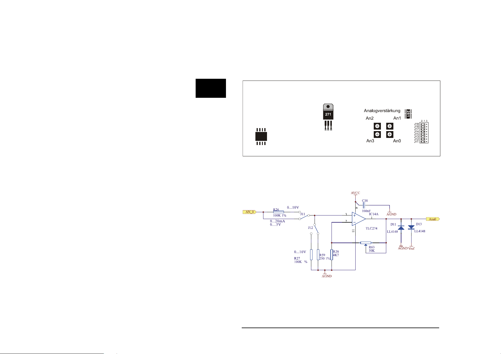
Setting the amplification
The analog inputs of the ICOM-200 / 201 have an adjustable input amplifier.
The amplification can be set to a factor between 1 and 10. This is done
continuously with potentiometers on the backside of the board.
Backside of board
The shematic below shows the input circuit available for each analog channel.
The diodes protect the Tiny-Tiger
peaks.
Wilke Technology GmbH • 0241/918900 • http://www.wilke.de/ • support@wilke.de
2-18
®
pins against negative voltages and voltage
Page 27
ICOM-200 / 201
'-------------------------------------------------------------------'----- ICOM200_AD.TIG
'--------------------------------------------------------------------
#include define_a.inc
user_var_strict
TASK Main
BYTE k
ARRAY Value(4) OF WORD
DIR_PORT 8,0
DIR_PORT 7,0
INSTALL_DEVICE #lcd,"LCD2.TDD",0,0,0EEH,1,150,11H' LCD-1=128x64, 150
KB/s
INSTALL_DEVICE #4, "ANALOG1.TDD" ' Analog-Inputs installieren
OUT 8,11111111b,11011111b ' set CTRL-Pins of T6963C
OUT 8,10000000b,255
LOOP 99999
FOR K = 0 TO 3 ' 4 Kanaele
GET #4, #K, 2, Value(K) ' Wert aus AD-Wandler lesen
NEXT ' naechster Kanal
PRINT #lcd, "<1>"; ' Bildschirm loeschen
FOR K = 0 TO 3 ' 4 Kanaele
PRINT #lcd, "AD"; K; ":"; ' Kanal-Nr. anzeigen
PRINT #lcd, Value(K) ' Wert auf LC-Display ausgeben
NEXT ' naechster Kanal
WAIT_DURATION 100 ' 100 ms warten
ENDLOOP
END
2
Wilke Technology GmbH • 0241/918900 • http://www.wilke.de/ • support@wilke.de 2-19
Page 28

2
ICOM-manual
MF-2 Keyboard
The ICOM-200 and ICOM-201 both have a connector for a MF2 keyboard.
With this it is possible to connect a common PC keyboard to the ICOM.
For the connection of a MF2 keyboard two pins of the Tiny-Tiger
For the ICOM-200/201 those are pins P84 and P85 of the Tiny-Tiger
These pins are directly lead to the MF2 plug on the left side of the ICOM.
®
are needed.
®
module.
Wilke Technology GmbH • 0241/918900 • http://www.wilke.de/ • support@wilke.de
2-20
Page 29

ICOM-200 / 201
'-------------------------------------------------------------------'----- ICOM200_MF2.TIG
'--------------------------------------------------------------------
USER_VAR_STRICT
#project_model pm_min
#include mf2_tr.inc '' subroutines of the Transport Layer
#define LCD 1
#define KEYB1 20
'' Set of Keyboard Variables;
WORD wKeybDevId1 '' Keyboard Device Number
LONG lKeybExtFlags1 '' Keyboard Flags
BYTE bKeybActLang1 '' Keyboard Layout( Language )
TASK Main
WORD wKey
BYTE bIsActive
LONG lComplexMask
dir_port 8, 00000000b
out 8,00010000b, 0
' LCD-4=240x128, 150 KB/s
install_device #lcd,"LCD2.TDD",0,0,0EEH,1,150,11H
INSTALL DEVICE #KEYB1, "MF2_8485.TDD" '' L84=clock, L85=data
'' Initialize the Keyboard Variables
wKeybDevId1 = KEYB1
lKeybExtFlags1 = 0
bKeybActLang1 = LANG_GERMAN
CALL InitKeybTables( bKeybActLang1 )
CALL InitKeybDev( wKeybDevId1 )
PRINT #LCD,"<1>";
PRINT #LCD,"<1Bh>c";CHR$(0);"<F0h>";
USING "UH<3><2> 0.0,0.0.3"
CALL SetLcdOutputPos( LCD, 0, 0 )
PRINT #LCD, "LowByte : "
CALL SetLcdOutputPos( LCD, 0, 1 )
PRINT #LCD, "HighByte: "
CALL SetLcdOutputPos( LCD, 0, 2 )
PRINT #LCD, "Ctrl Key: "
CALL SetLcdOutputPos( LCD, 0, 3 )
PRINT #LCD, "Status : "
run_task p8
WHILE 1 = 1
'' Read a key from keyboard buffer and translate it into ASCII
CALL GetAsciiKey( wKeybDevId1, lKeybExtFlags1, bKeybActLang1, wKey)
IF wKey <> 0 THEN
2
Wilke Technology GmbH • 0241/918900 • http://www.wilke.de/ • support@wilke.de 2-21
Page 30

2
ICOM-manual
CALL SetLcdOutputPos( LCD, 9, 0 )
PRINT_USING #LCD, wKey BITAND 0ffh
CALL SetLcdOutputPos( LCD, 9, 1 )
PRINT_USING #LCD, ( wKey SHR 8 ) BITAND 0ffh
'' Check whether a control key is pressed
CALL SetLcdOutputPos( LCD, 11, 2 )
CALL CheckKeybFlags(__KF_SHIFTRIGHT_DOWN,lKeybExtFlags1,bIsActive)
IF bIsActive = TRUE THEN
PRINT #LCD, "Shift_R"
ENDIF
CALL CheckKeybFlags(__KF_SHIFTLEFT_DOWN,lKeybExtFlags1,bIsActive)
IF bIsActive = TRUE THEN
PRINT #LCD, "Shift_L"
ENDIF
CALL CheckKeybFlags(__KMT_CTRLRIGHT_DOWN,lKeybExtFlags1,bIsActive)
IF bIsActive = TRUE THEN
PRINT #LCD, "Ctrl_R "
ENDIF
CALL CheckKeybFlags(__KF_CTRLLEFT_DOWN,lKeybExtFlags1,bIsActive)
IF bIsActive = TRUE THEN
PRINT #LCD, "Ctrl_L "
ENDIF
CALL CheckKeybFlags(__KMT_ALTRIGHT_DOWN,lKeybExtFlags1,bIsActive)
IF bIsActive = TRUE THEN
PRINT #LCD, "Alt_R "
ENDIF
CALL CheckKeybFlags(__KF_ALTLEFT_DOWN,lKeybExtFlags1,bIsActive)
IF bIsActive = TRUE THEN
PRINT #LCD, "Alt_L "
ENDIF
lComplexMask = &
__KF_SHIFTRIGHT_DOWN BITOR __KF_SHIFTLEFT_DOWN BITOR &
__KMT_CTRLRIGHT_DOWN BITOR __KF_CTRLLEFT_DOWN BITOR &
__KMT_ALTRIGHT_DOWN BITOR __KF_ALTLEFT_DOWN
CALL CheckKeybFlags( lComplexMask, lKeybExtFlags1, bIsActive)
IF bIsActive = FALSE THEN
PRINT #LCD, "No Spec"
ENDIF
'' Is Code extended or normal ?
CALL SetLcdOutputPos( LCD, 11, 3 )
IF wKey BITAND 0ffh = 0 THEN
PRINT #LCD, "Extended"
CALL SetLcdOutputPos( LCD, 13, 0 )
PRINT #LCD, "Null "
CALL SetLcdOutputPos( LCD, 13, 1 )
PRINT #LCD, "EScan"
ELSE
PRINT #LCD, "Normal "
CALL SetLcdOutputPos( LCD, 13, 0 )
PRINT #LCD, "Ascii"; ";"; CHR$( wKey BITAND 0ffh )
CALL SetLcdOutputPos( LCD, 13, 1 )
PRINT #LCD, "Scan "
ENDIF
Wilke Technology GmbH • 0241/918900 • http://www.wilke.de/ • support@wilke.de
2-22
Page 31

ICOM-200 / 201
ENDIF
ENDWHILE
END
SUB SetLcdOutputPos( WORD wDevId; BYTE Column, Row )
PRINT #wDevId, "<1BH>A";CHR$( Column );CHR$( Row );"<0F0H>";
END
Task p8
BYTE ever
for ever = 0 to 0 step 0
out 8,00010000b, 0
next
END
2
Wilke Technology GmbH • 0241/918900 • http://www.wilke.de/ • support@wilke.de 2-23
Page 32

ICOM-manual
TINY-Tiger® Pins
2
The ICOM-200/201 has, in addition to the extended I/O pins with optocouplers
and transistors, some standard pins of the TINY-Tiger
At the DB37 connector the pins P71, P72 and P73 are lead out.
Tiny-Tiger pin DB37 connector
P71 12
P72 31
P73 13
®
.
Pin layout 37-ch. D-Sub connector
The 37-ch. D-Sub connector carries all available I/O pins except for serial port
1.
Wilke Technology GmbH • 0241/918900 • http://www.wilke.de/ • support@wilke.de
2-24
Page 33

ICOM-200 / 201
Technical data
LCD: Graphical display with 128 x 64 pixel and LED
backlight.
Keyboard: Keyboard matrix with 20 keys and additional
connection for MF2 keyboard
Sound: Beeper, e.g. as keyboard click.
Interface: 1 x RS232
1 x RS232/RS485 selectable.
Analog In: Settable to
4 x 0...5V resp. 0...10V or 0...20mA
Input amplifier:
1 < V < 10
Resolution 10 bit.
Inputs: 8 x opto in 5 to 12V (higher range possible through
external resistor).
Outputs: 8 x Darlington, with protective diode.
max 50V/500mA @ 1 chanel, duty = 10%
50mA @ 8 chanels, duty = 100%
Supply: RUN: 8...12V DC, 450mA
SLEEP: approx. 25mA
2
Size: approx. 196 x 88,5 x 40mm(LxBxH)
Connections: RS232 with DB9
All other with DB37
Temp. range: -20° to 50°C
expanded temp range on request
Wilke Technology GmbH • 0241/918900 • http://www.wilke.de/ • support@wilke.de 2-25
Page 34

Page 35

ICOM-241
3 ICOM-241
The ICOM-241 is the most cost effective solution of the ICOM family. The
processor used is a Tiny-Tiger
The ICOM-241 has eight transistor outputs and four optocoupler inputs. From
both serial ports, port 0 can be configured as RS485 interface as well.
For measurement of analog signals the ICOM-241 possesses four analog
inputs with a hardware resolution of 10 bit (12 bit by software interpolation).
The maximum input voltage for the analog inputs is 5V DC.
®
Economy.
3
Components side ICOM-241
Wilke Technology GmbH • 0241/918900 • http://www.wilke.de/ • support@wilke.de 3-1
Page 36

3
ICOM-manual
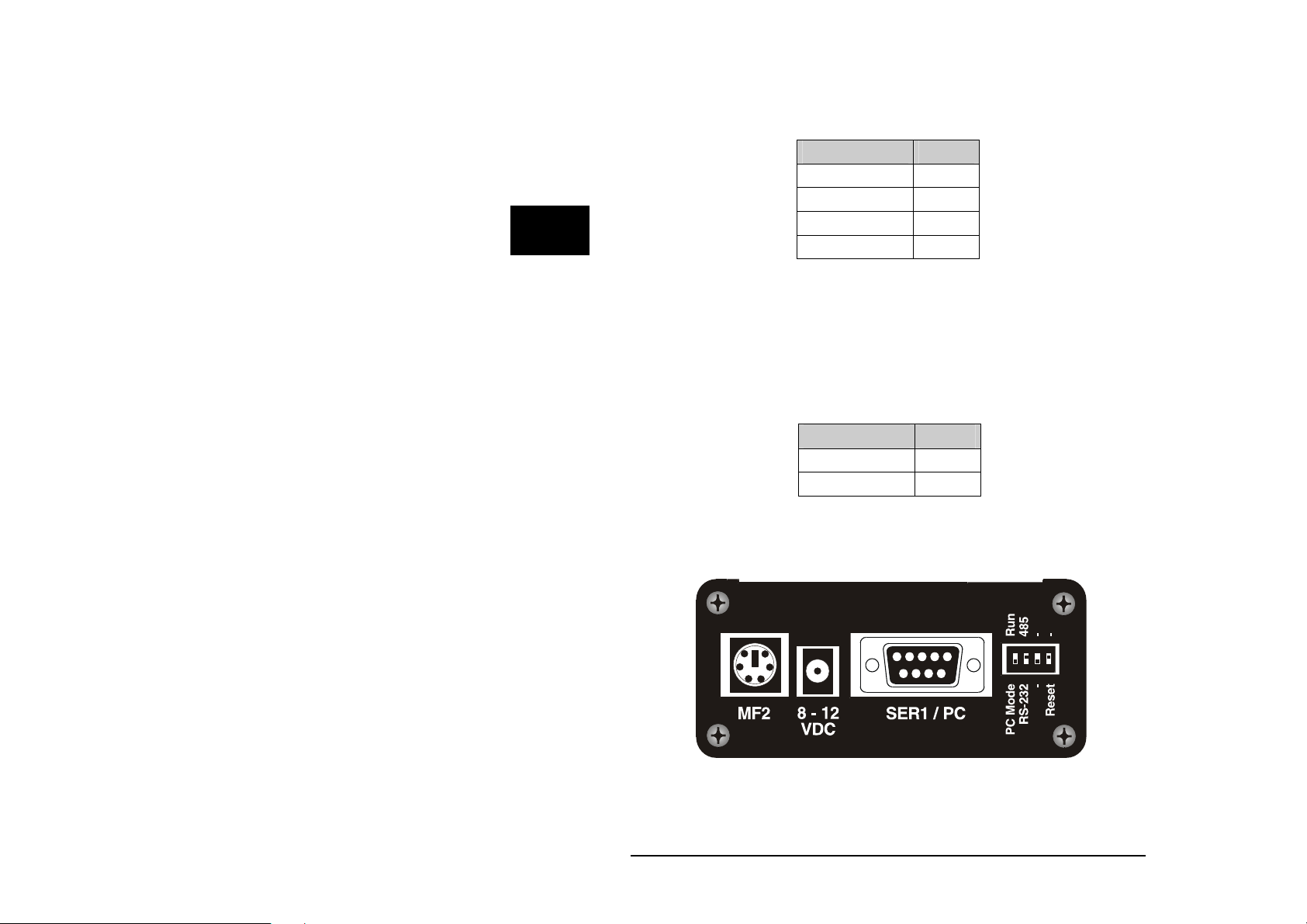
First steps
Power supply
The ICOM-200/201 uses a power supply with 8-12 VDC, 1A. Minus is placed
on the pin of the power supply connector. The current consumption is,
depending on the application, up to 400mA.
PC-Mode
After a reset or power-down the Tiny-Tiger® Economy inside the ICOM-241 is
testing if the PC mode pin is „low“. In this case, the ICOM switches to PC
mode/Debug mode. Is the pin „high“, the ICOM starts in run mode. The time
between power-on and first activity on the I/O pins is approx. 230 msec.
To set the ICOM-241 to PC mode, a reset or power-down is needed. Setting
the DIP switch to PC mode while in run mode is not sufficient.
Side view ICOM-241
Wilke Technology GmbH • 0241/918900 • http://www.wilke.de/ • support@wilke.de
3-2
Page 37

ICOM-241
RUN mode
If the DIP-switch “PC/Run” is in position “Run”, the program in the ICOM-241
is executed immediately after a reset. Debugging is not possible in this mode.
Program download
A program created with the Tiger software is downloaded into ICOM-241
through the 9-pin Sub-D connector. To download the following has to be done:
Connect a power supply 8-12 V DC (Polarity: Inner contact = minus,
outer contact = plus)
Connect ICOM-241 and PC with 9-pin D-Sub cable
Set DIP switch of ICOM-241 to PC mode
Set the reset DIP switch to „Reset“ and back to original position
Start download at the PC.
Serial port 1 / Download DB-9 plug
TXD 2
RXD 3
GND 5
3
Wilke Technology GmbH • 0241/918900 • http://www.wilke.de/ • support@wilke.de 3-3
Page 38

ICOM-manual
Opto inputs
The ICOM-241 has eight optocoupler inputs suited for an input voltage range
of 5...12 VDC. To use higher input voltages, as 24V for example, an additional
serial resistor in the input line is used. The resistor value is selected in
accordance to 4...50mA input current needed for the logical “1” level.
The internal resistance is 680 Ohm / 0,25 W. If now another input voltage is
needed, the totally required resistance can be calculated with the following
formula:
3
= (UE-1,3V)/I
R
ges
I
R
Example:
Is e.g. an input voltage of 24 V with a current of 10 mA wanted, you get from
the above formula Rges = 2270 Ohm. This means either the internal 680 Ohm
resistor has be replaced with a 2200 Ohm resistor (rounded to norm value), or
a resistor of 1590 Ohm has to be connected in series.
Attention:
When calculating the protective resistance the maximum dissipation of the
resistor has to be considered!
Tiny-Tiger® Port Optokoppler DB-25 socket
P80 Opto In0 1
P81 Opto In1 14
P82 Opto In2 2
P83 Opto In3 15
- Opto GND 3
The following program reads the status of the optocoupler inputs into a
variable and sends it out through serial port 0.
D
UE = Input voltage
= Current into the optocoupler
D
= Total resistance
ges
Wilke Technology GmbH • 0241/918900 • http://www.wilke.de/ • support@wilke.de
3-4
Page 39

ICOM-241
'--------------------------------------------------------------------
'----- ICOM241_OPTOIN.TIG
'--------------------------------------------------------------------
#include define_a.inc
user_var_strict
TASK Main
BYTE wert
DIR_PORT 8,0fh ' low nibble als Input
INSTALL_DEVICE #SER, "SER1B_K1.TDD",&
BD_9_600, DP_8N, JA, BD_9_600, DP_8N, JA
'-------------------------------------------------------------------'-------- Optokoppler Inputs ----------------------------'--------------------------------------------------------------------
OP:
IN 8,wert ' Optokoppler Inputs einlesen
wert = wert & 00001111b ' High nibble ausblenden
put #ser, #0, wert ' Wert auf Ser 0 ausgeben
GOTO op ' Sprung nach "OP"
END
3
Wilke Technology GmbH • 0241/918900 • http://www.wilke.de/ • support@wilke.de 3-5
Page 40

ICOM-manual
Power outputs
The power outputs of the ICOM-241 are extended outputs of the Tiny-Tiger®
Economy, which are equiped with a driver IC type TD62083 or compatible.
This IC has got eight open collector outputs.
The power outputs are lead to the 25-ch. Sub-D connector. The pin OVCC is
connected to a internal protector diode, so the outputs are secured against
overvoltage. This pin normally should have the same voltage potential as the
voltage to be switched.
3
Tiny-Tiger® Port Power-Outputs DB-25 Pin
P60 Out 0 12
P61 Out 1 11
P62 Out 2 10
P63 Out 3 9
P64 Out 4 8
P65 Out 5 7
P66 Out 6 6
P67 Out 7 5
OVCC 13
'--------------------------' Demoprogramm ICOM-241
' Name: ICOM241_powerout.tig
'---------------------------
TASK MAIN
BYTE X, I
LOOP 99999999 ' Schleife
FOR I = 0 to 255 ' For Next Schleife
OUT 6,255,I ' Bitmuster ausgeben1
NEXT ' Ende For Next Schleife
ENDLOOP
END
Wilke Technology GmbH • 0241/918900 • http://www.wilke.de/ • support@wilke.de
3-6
Page 41

ICOM-241
Serial interface
As a standard the ICOM-241 has two serial interfaces. From these the port
Ser0 can by choice be configured as RSR232 or RS485 interface. The port
Ser1 always is a RS232 interface. In PC mode this port is used for
downloading the program into the ICOM 241. In Run mode it can be used as a
usual RS232 interface.
Detailled information about the serial interfaces can be read after in the
BASIC-Tiger
®
„Device driver“ manual.
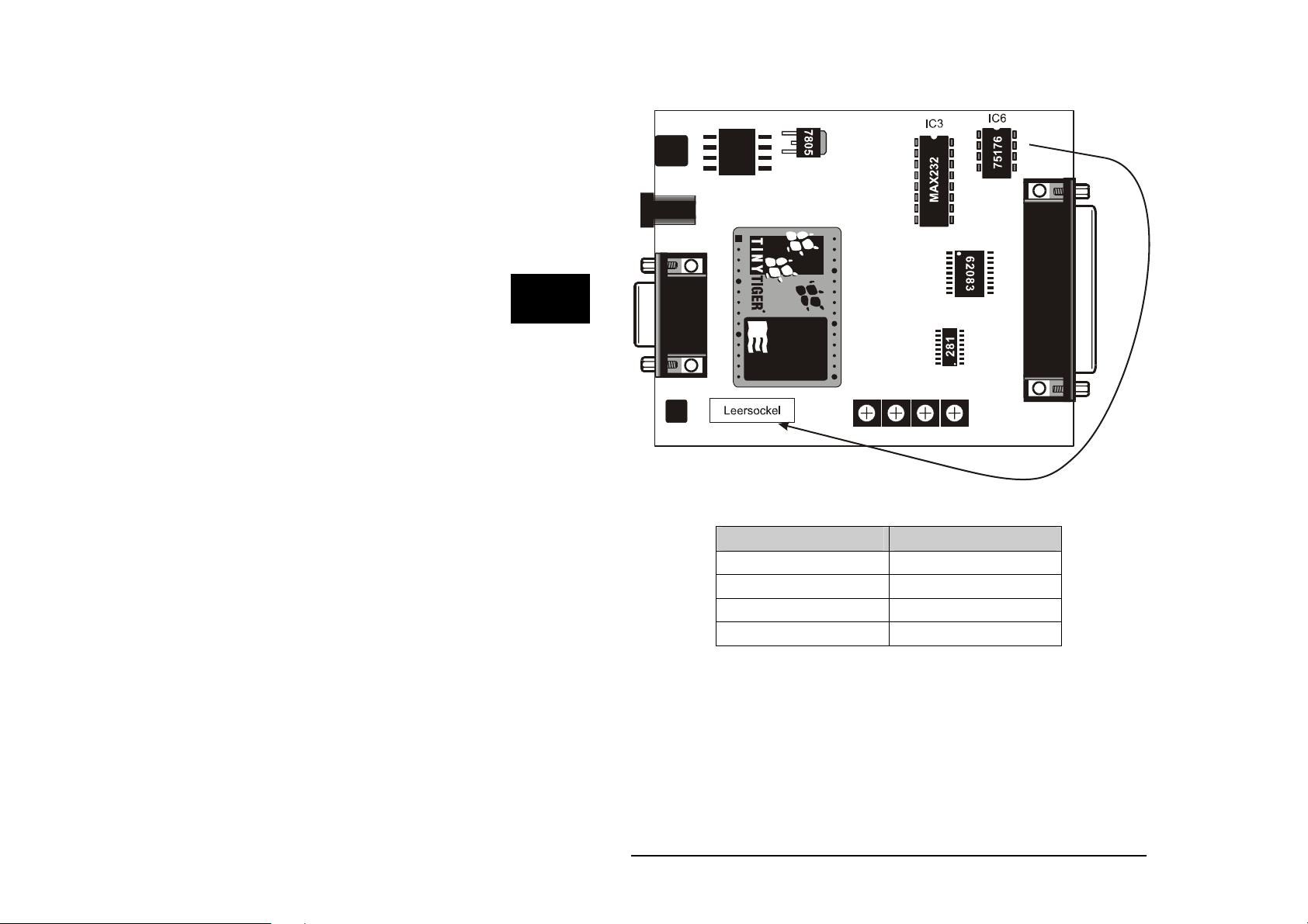
RS232
To configure port Ser0 as RS232 interface, the IC3 (MAX232) must be placed
into the appropriate socket and IC6 ( SN75176) has to removed from its
socket. After that the DIP switch at the left side of the chassis has to be
switched to RS232. It is recommended to place the IC 6 (SN75176) into the
dummy socket, so it’s always available when needed again.
3
Wilke Technology GmbH • 0241/918900 • http://www.wilke.de/ • support@wilke.de 3-7
Page 42
3
ICOM-manual
The pins of serial port Ser0 are located on the DB25 connector. The pin layout
is shown in the table below:
RS232 Pin DB25 socket
TxD0 18
RxD0 17
CTS0 19
RTS0 20
Layout of DB25 connector (RS232)
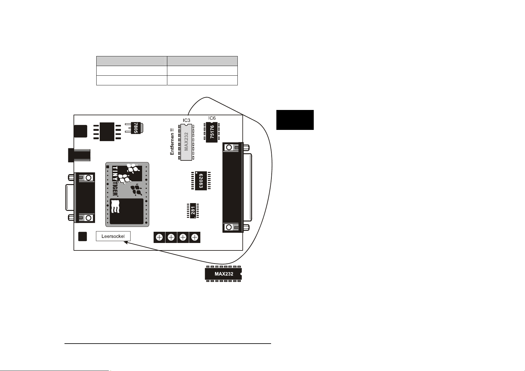
RS 485
The configuration of port Ser0 as RS485 interface is done by placing the IC6
(SN75176) into the 8 pin DIL socket. The IC3 (MAX232) has to be removed
and placed into the dummy socket. The DIP switch on the left side of the
chassis has to be switched to RS485 position.
Wilke Technology GmbH • 0241/918900 • http://www.wilke.de/ • support@wilke.de
3-8
Page 43
ICOM-241
Placing or removing of the ICs is only allowed without power supply.
RS485 Pin DB25 socket
!
TXD0 (A) 18
RXD0 (B) 17
Layout of DB25 socket (RS485)
3
Attention: Never place IC3 and IC6 at the same time, as this could lead to
destruction of the serial port or the driver ICs !
The following sample program receives serial data through serial port 0.
Wilke Technology GmbH • 0241/918900 • http://www.wilke.de/ • support@wilke.de 3-9
Page 44

3
ICOM-manual
'-------------------------------------------------------------------'----- ICOM200_RS232.TIG
'--------------------------------------------------------------------
#include define_a.inc
user_var_strict
TASK Main
BYTE i,k
DIR_PORT 8,0
INSTALL DEVICE #lcd,"LCD2.TDD",0,0,0EEH,1,150,11H' LCD-1=128x64, 150
KB/s
INSTALL DEVICE #SER, "SER1B_K1.TDD",&
BD_9_600, DP_8N, JA, BD_9_600, DP_8N, JA
OUT 8,11111111b,11011111b ' set CTRL-Pins of T6963C
OUT 8,10000000b,255 ' Buzzer off !
LOOP 999999999 ' Endlosschleife
GET #ser,#0,#1,1,i ' Eingangsbufferfüllstand
IF I > 0 THEN
GET #ser,#0,1,k ' Seriellen Eingangsbuffer lesen
PRINT #lcd,"Taste = "; chr$(k) ' Ausgabe auf dem LCD
ENDIF
ENDLOOP
END
Wilke Technology GmbH • 0241/918900 • http://www.wilke.de/ • support@wilke.de
3-10
Page 45

ICOM-241
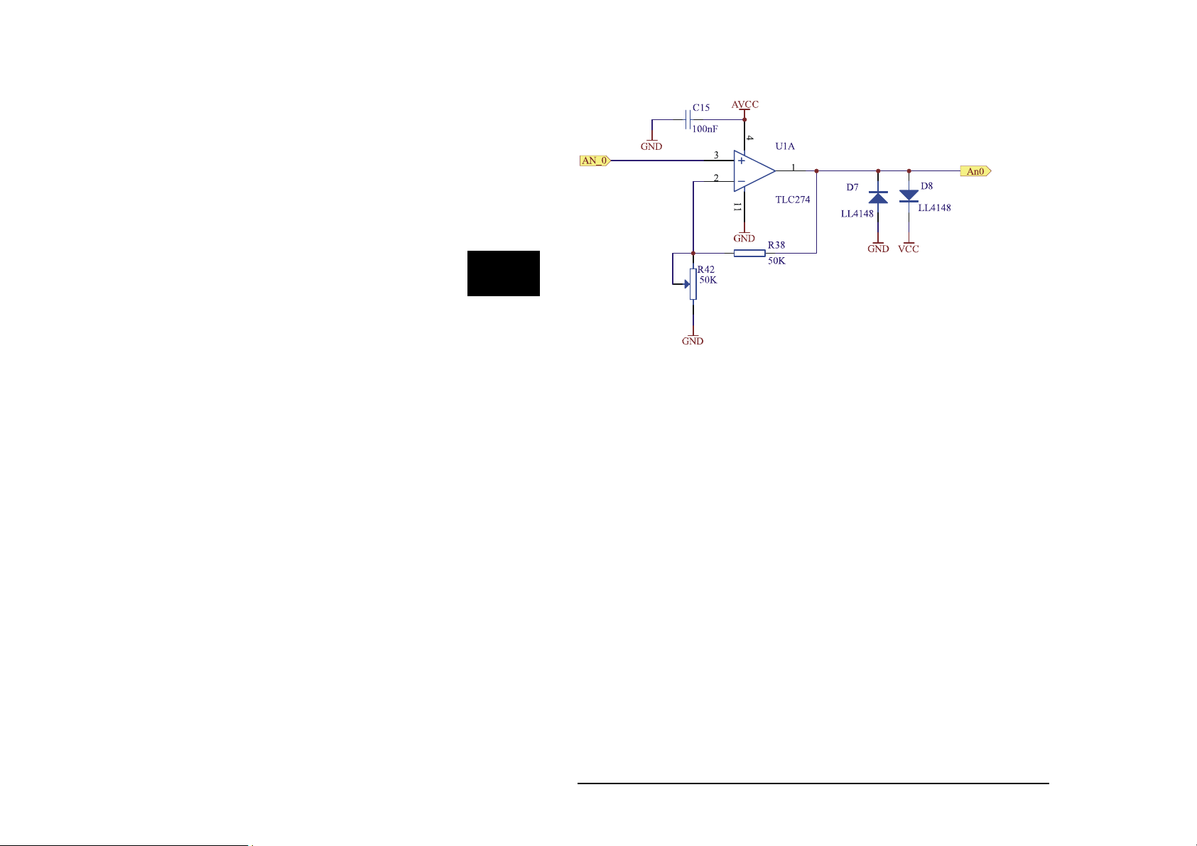
Analog inputs
The analog inputs of the ICOM-241 have an input range from 0...5V DC. The
hardware resolution is 10 bit and can be raised to 12 bit by software
interpolation when needed. To be able to measure small signals each analog
input is equipped with an OpAmp. The amplification can be set to a value
between 1 and 10 by potis.
3
View of components side with potis of analog amplifiers
Analog channels DB25 socket
An0 22
An1 23
An2 24
An3 25
Pin layout of DB25 connector (analog channels)
Wilke Technology GmbH • 0241/918900 • http://www.wilke.de/ • support@wilke.de 3-11
Page 46
3
3
ICOM-manual
ICOM-manual
Circuit of analog inputs
Wilke Technology GmbH • 0241/918900 • http://www.wilke.de/ • support@wilke.de
Wilke Technology GmbH • 0241/918900 • http://www.wilke.de/ • support@wilke.de
3-12
3-12
Page 47
ICOM-241
'--------------------------------------------------------------------
'----- ICOM200_AD.TIG
'--------------------------------------------------------------------
#include define_a.inc
user_var_strict
TASK Main
BYTE k
ARRAY Value(4) OF WORD
DIR_PORT 8,0
DIR_PORT 7,0
INSTALL_DEVICE #lcd,"LCD2.TDD",0,0,0EEH,1,150,11H' LCD-1=128x64, 150
KB/s
INSTALL_DEVICE #4, "ANALOG1.TDD" ' Analog-Inputs installieren
OUT 8,11111111b,11011111b ' set CTRL-Pins of T6963C
OUT 8,10000000b,255
LOOP 99999
FOR K = 0 TO 3 ' 4 Kanaele
GET #4, #K, 2, Value(K) ' Wert aus AD-Wandler lesen
NEXT ' naechster Kanal
PRINT #lcd, "<1>"; ' Bildschirm loeschen
FOR K = 0 TO 3 ' 4 Kanaele
PRINT #lcd, "AD"; K; ":"; ' Kanal-Nr. anzeigen
PRINT #lcd, Value(K) ' Wert auf LC-Display ausgeben
NEXT ' naechster Kanal
WAIT_DURATION 100 ' 100 ms warten
ENDLOOP
END
3
Wilke Technology GmbH • 0241/918900 • http://www.wilke.de/ • support@wilke.de 3-13
Page 48

3
ICOM-manual
Pin layout 25-pin D-Sub connector
The 25-pin D-Sub connector carries all available I/O pins (except for serial
port 0) of the ICOM-241.
Wilke Technology GmbH • 0241/918900 • http://www.wilke.de/ • support@wilke.de
3-14
Page 49

ICOM-241
Technical data
Interface: 1 x RS232
1 x RS232/RS485 selectable.
Analog In: 4 x 0...5V with input amplifier 1 < V < 10
Resolution 10 bit.
Inputs: 4 x opto in 5 to 12V DC
Outputs: 8 x Darlington, with protective diode.
max 50V/500mA @ 1 chanel, duty = 10%
50mA @ 8 chanels, duty = 100%
Supply: 8...12V DC, 90mA
Size: approx. 106 x 88,5 x 40mm(LxBxH)
Connections: RS232 with DB9
All other with DB25
3
Wilke Technology GmbH • 0241/918900 • http://www.wilke.de/ • support@wilke.de 3-15
Page 50

3
ICOM-manual
ICOM 241 – 24V
The ICOM-241 – 24V is a variant of the ICOM 241. It needs a supply voltage
between 14V and 24V DC. The serial port SER1 is realized with a male 9 pol.
Sub D Connector.
seriel port 1 / download DB-9 Connector (male)
TXD 3
RXD 2
GND 5
Wilke Technology GmbH • 0241/918900 • http://www.wilke.de/ • support@wilke.de
3-16
Page 51

ICOM-241
Connection to PC
For programme download, debugging and other communication with a PC use
a crosslinked cable (null modem)
Technical data
Interface: 1 x RS232
1 x RS232/RS485 selectable.
Analog In: 4 x 0...5V with input amplifier 1 < V < 10
Resolution 10 bit.
Inputs: 4 x opto in 5 to 12V DC
Outputs: 8 x Darlington, with protective diode.
max 50V/500mA @ 1 chanel, duty = 10%
50mA @ 8 chanels, duty = 100%
3
Supply: 14...24V DC, 95mA
Size: approx. 106 x 88,5 x 40mm(LxBxH)
Connections: RS232 with DB9 male
All other with DB25
Wilke Technology GmbH • 0241/918900 • http://www.wilke.de/ • support@wilke.de 3-17
Page 52

Page 53

Hints and Help
4 Hints and help
When you have problems with a Tiger-BASIC® program:
Try to reduce the problem to a short and simple sample program.
Maximum should be one page, mostly a view lines will do.
Which version of the compiler do you use (see About... in menue
Help)?
Which versions have the device drivers involved (see Device driver
list in menue View)?
Describe the faultive situaltion as detailled as possible.
In what context does the error occur?
Does the error occur always or only occasionally?
Include all your communication numbers as Fax, Phone etc. in your
request, so we can help you as fast as possible.
BASIC-Tiger® Service Hotline:
+49 (0)241 / 15 15 99
4
Wilke Technology GmbH
Krefelder Str. 147
P.O. Box 1727
D-52070 Aachen / Germany
Phone: +49 (0) 24
Fax: +49 (0) 24
eMail:
Wilke Technology GmbH • 0241/918900 • http://www.wilke.de/ • support@wilke.de 4-1
support@wilke-technology.com
1/918900
1/9189044
Page 54

4
ICOM-manual
Wilke Technology GmbH • 0241/918900 • http://www.wilke.de/ • support@wilke.de
4-2
Page 55

Index
5 Register
Amplification 2-18
analog inputs 2-15, 3-12
Display 2-8
Goldcap 2-4
I/O pins 2-24
ICOM-241 3-1
LC display 2-8
Loading time 2-5
Matrix keyboard 2-6
MF2 keyboard 2-20
Opto inputs 2-11, 3-4
PC mode 2-2
Power outputs 2-13, 3-6
Power supply 2-2, 3-2
Program download 2-3
RS232 interface 2-9, 3-8
RS485 interface 2-10, 3-9
RUN mode 2-3
Technical data 2-25, 3-16
5
Wilke Technology GmbH • 0241/918900 • http://www.wilke.de/ • support@wilke.de 5-1
 Loading...