

Page 1

ERserver
IBM xSeries 205
Type 8480
Hardware Maintenance Manual and Troubleshooting
Guide
Page 2

Page 3

ER s e r v e r
IBM xSeries 205
Type 8480
Hardware Maintenance Manual and Troubleshooting
Guide
Page 4

Note
Before using this information and the product it supports, read Appendix C, “Notices”, on page 151.
Fifth Edition (February 2003)
The following paragraph does not apply to the United Kingdom or any country where such provisions are
inconsistent with local law:
INTERNATIONAL BUSINESS MACHINES CORPORATION PROVIDES THIS PUBLICATION ″AS IS″ WITHOUT
WARRANTY OF ANY KIND, EITHER EXPRESS OR IMPLIED, INCLUDING, BUT NOT LIMITED TO, THE IMPLIED
WARRANTIES OF MERCHANTABILITY OR FITNESS FOR A PARTICULAR PURPOSE. Some states do not allow
disclaimer of express or implied warranties in certain transactions, therefore, this statement may not apply to you.
This publication could include technical inaccuracies or typographical errors. Changes are periodically made to the
information herein; these changes will be incorporated in new editions of the publication. IBM may make
improvements and/or changes in the product(s) and/or the program(s) described in this publication at any time.
This publication was developed for products and services offered in the United States of America. IBM may not offer
the products, services, or features discussed in this document in other countries, and the information is subject to
change without notice. Consult your local IBM representative for information on the products, services, and features
available in your area.
Requests for technical information about IBM products should be made to your IBM reseller or IBM marketing
representative.
© Copyright International Business Machines Corporation 2002. All rights reserved.
US Government Users Restricted Rights – Use, duplication or disclosure restricted by GSA ADP Schedule Contract
with IBM Corp.
Page 5
About this manual
This manual contains diagnostic information, a Symptom-to-FRU index, service
information, error codes, error messages, and configuration information for the IBM
Eserver xSeries™205.
Important: The field replaceable unit (FRU) procedures are intended for trained
servicers who are familiar with IBM xSeries products. See the parts
listing in “System” on page 110 to determine if the component being
replaced is a customer replaceable unit (CRU) or a field replaceable
unit (FRU).
Important safety information
Be sure to read all caution and danger statements in this book before performing
any of the instructions. See “Safety information” on page 117.
Leia todas as instruções de cuidado e perigo antes de executar qualquer operação.
Prenez connaissance de toutes les consignes de type Attention et Danger avant de
procéder aux opérations décrites par les instructions.
®
Online support
Lesen Sie alle Sicherheitshinweise, bevor Sie eine Anweisung ausführen.
Accertarsi di leggere tutti gli avvisi di attenzione e di pericolo prima di effettuare
qualsiasi operazione.
Lea atentamente todas las declaraciones de precaución y peligro ante de llevar a
cabo cualquier operación.
You can download the most current diagnostic, BIOS flash, and device driver files
from http://www.ibm.com/pc/support on the World Wide Web.
© Copyright IBM Corp. 2002 iii
Page 6

iv IBM xSeries 205 Type 8480: Hardware Maintenance Manual and Troubleshooting Guide
Page 7

Contents
About this manual .......................iii
Important safety information ....................iii
Online support .........................iii
Chapter 1. General information...................1
Related publications .......................1
Notices and statements in this book .................2
Features and specifications .....................3
Server controls, LEDs, and connectors ................4
Server controls and LEDs ....................4
Server connectors .......................5
Server power features......................6
Chapter 2. Configuring your server .................9
Using the Configuration/Setup Utility program ..............9
Starting the Configuration/Setup Utility program ............9
Using passwords .......................10
Enabling Broadcom NetXtreme Gigabit Ethernet Boot Agent ........13
Using the ServerGuide Setup and Installation CD ............13
ServerGuide features .....................13
Setup and configuration overview .................14
Typical operating-system installation ................15
Setting up or updating multiple servers ...............16
Installing your operating system without ServerGuide ..........16
Configuring the Gigabit Ethernet controller ...............16
Using the SCSISelect Utility program .................17
Starting the SCSISelect Utility program ...............17
SCSISelect menu choices ....................18
Using the Boot Menu program ...................18
Chapter 3. Diagnostics .....................21
General checkout ........................21
Checkout procedure ......................22
Diagnostic tools overview .....................23
POST ............................23
POST beep codes ......................24
Error logs ..........................24
ServerGuide error symptoms ....................24
Small computer system interface messages ..............25
Diagnostic programs and error messages ...............25
Text messages ........................26
Starting the diagnostic programs .................26
Diagnostic error message tables .................28
Recovering from a POST/BIOS update failure .............29
Power checkout ........................29
Troubleshooting the Ethernet controller ................30
Network connection problems ..................30
Ethernet controller troubleshooting chart ..............31
Ethernet controller messages ..................32
Chapter 4. Installing options ...................33
System reliability considerations ..................33
Major components of the IBM Eserver xSeries 205 Type 8480 .......34
© Copyright IBM Corp. 2002 v
Page 8

System and PCI extender boards ..................35
System board internal cable connectors...............36
System board external connectors.................37
Optional system-management adapter component locations .......37
Installation guidelines ......................38
System reliability considerations .................38
Handling static-sensitive devices .................38
Moving the stabilizing feet .....................39
Removing the side cover .....................40
Removing the frame-support bracket .................41
Working with adapters ......................42
Adapter considerations .....................42
Installing an adapter ......................43
Installing a SCSI adapter ....................45
Cabling a RAID adapter or single SCSI channel using one hot-swap drive SCSI
backplane ..........................45
Installing internal drives ......................47
Internal drive bays ......................47
Preinstallation steps ......................48
Power and signal cables for internal drives .............49
Installing a drive in bay 1, 2, 3, or 4 ................50
Installing a non-hot-swap hard disk drive in bay 5, 6, or 7 ........52
Installing a hot-swap hard disk drive in bay 5, 6, or 7 ..........54
Installing memory modules ....................56
Installing a security rope clip ....................57
Replacing the side cover .....................59
Replacing the battery ......................60
Connecting external options ....................61
Video connector .......................62
Keyboard connector ......................62
Mouse connector .......................62
Parallel connector .......................62
Serial connectors .......................63
Gigabit Ethernet port ......................63
Universal Serial Bus (USB) connectors ...............64
Audio connectors .......................64
Optional system-management adapter ports .............65
Chapter 5. Field replaceable units .................67
Removing the front bezel .....................67
Power button .........................68
Microprocessor / fan sink .....................70
Hot-swap hard disk drive cage ...................71
Hot-swap backplane .......................72
Power supply .........................73
Rear fan ...........................74
Extender card .........................75
System board .........................77
CD-ROM drive .........................78
Diskette drive .........................79
Bezel release latch .......................80
Top/side cover .........................81
Handle assembly ........................82
Adapter retainer ........................83
Chapter 6. Symptom-to-FRU index .................85
vi IBM xSeries 205 Type 8480: Hardware Maintenance Manual and Troubleshooting Guide
Page 9

Beep symptoms ........................85
No-beep symptoms .......................87
Diagnostic panel system error LED .................87
Diagnostic error codes ......................89
Error symptoms ........................93
Power-supply LED errors .....................95
POST error codes ........................95
POST (ISPR) error procedures ...................98
ServeRAID error codes .....................100
Service processor error codes ...................102
SCSI error codes .......................102
Temperature error messages ...................102
Fan error messages ......................103
Power error messages .....................103
System shutdown .......................104
Voltage related system shutdown.................104
Temperature related system shutdown ...............104
DASD checkout ........................105
Host built-in self test (BIST) ....................105
Bus fault messages.......................105
Undetermined problems .....................106
Problem determination tips ....................107
Chapter 7. Parts listing xSeries 205 Type 8480............109
System ...........................110
Keyboard CRUs ........................111
Power cords .........................112
Appendix A. Getting help and technical assistance ..........115
Before you call ........................115
Using the documentation .....................115
Getting help and information from the World Wide Web .........115
Software service and support ...................116
Hardware service and support ...................116
Appendix B. Related service information ..............117
Safety information .......................117
General safety........................117
Electrical safety .......................118
Safety inspection guide ....................119
Handling electrostatic discharge-sensitive devices ..........120
Grounding requirements ....................121
Notice for customers in the State of California ............121
Safety notices (multilingual translations) ..............121
Appendix C. Notices ......................151
Edition notice .........................151
Trademarks..........................152
Important notes ........................152
Electronic emission notices ....................153
Federal Communications Commission (FCC) statement ........153
Industry Canada Class B emission compliance statement........154
Avis de conformité à la réglementation d’Industrie Canada .......154
European Union EMC Directive conformance statement ........154
Japanese Voluntary Control Council for Interference (VCCI) statement 154
Power cords .........................154
Contents vii
Page 10

viii IBM xSeries 205 Type 8480: Hardware Maintenance Manual and Troubleshooting Guide
Page 11

Chapter 1. General information
Your IBM Eserver xSeries 205 Type 8480 server is a high-performance server that
can be upgraded to a symmetric multiprocessing (SMP) server through a
microprocessor upgrade. It is ideally suited for networking environments that require
superior microprocessor performance, efficient memory management, flexibility, and
reliable data storage.
The xSeries 205 server contains several IBM X-Architecture
help increase server performance and reliability.
Your server comes with a limited warranty. If you have access to the World Wide
Web, you can obtain up-to-date information about your server model and other IBM
server products at http://www.ibm.com/pc/us/eserver/xseries/.
Your server serial number and model number are located on labels on the bottom of
the server and on the front below the bezel. You will need these numbers when you
register your server with IBM. The information label containing the serial number,
machine type, model number, and agency marks for your server is located on the
bottom of the server.
Related publications
This Hardware Maintenance Manual and Troubleshooting Guide contains
information to help you solve the problem yourself or to provide helpful information
to a service technician.
™
technologies, which
In addition to this Hardware Maintenance Manual and TroubleshootingGuide, the
following xSeries 205 Type 8480 documentation is provided with your server:
v Installation Guide
This printed publication contains setup and installation instructions.
v Rack Installation Instructions
This printed publication contains the instructions to install your server in a rack.
v Safety Book
This multilingual publication is provided in Portable Document Format (PDF) on
the IBM xSeries Documentation CD. It contains translated versions of the caution
and danger statements that appear in the documentation for your server. Each
caution and danger statement has an assigned number, which you can use to
locate the corresponding statement in your native language.
v User’s Guide
This publication is provided in PDF on the IBM xSeries Documentation CD. It
contains general information about your server, including information about
features, how to configure your server, how to use the ServerGuide
™
Setup and
Installation CD, and how to get help.
© Copyright IBM Corp. 2002 1
Page 12

v Option Installation Guide
This publication is provided in PDF on the IBM xSeries Documentation CD. It
contains instructions to install, remove, and connect optional devices supported
by your server.
Depending on your server model, additional publications might be included on the
IBM xSeries Documentation CD.
Notices and statements in this book
The caution and danger statements used in this book also appear in the multilingual
Safety Information book provided on the IBM xSeries Documentation CD. Each
caution and danger statement is numbered for easy reference to the corresponding
statements in the safety book.
The following types of notices and statements are used in this book:
v Note: These notices provide important tips, guidance, or advice.
v Important: These notices provide information or advice that might help you avoid
inconvenient or problem situations.
v Attention: These notices indicate possible damage to programs, devices, or
data. An attention notice is placed just before the instruction or situation in which
damage could occur.
v Caution: These statements indicate situations that can be potentially hazardous
to you. A caution statement is placed just before the description of a potentially
hazardous procedure step or situation.
v Danger: These statements indicate situations that can be potentially lethal or
extremely hazardous to you. A danger statement is placed just before the
description of a potentially lethal or extremely hazardous procedure step or
situation.
2 IBM xSeries 205 Type 8480: Hardware Maintenance Manual and Troubleshooting Guide
Page 13

Features and specifications
The following table provides a summary of the features and specifications for your
server.
Microprocessor: Supports one
microprocessor — Intel Pentium
with 128 KB, 256 KB, or 512 KB
Level-2 cache and 400 MHz or 533
MHz front side bus (FSB) Memory:
v Minimum: 128 MB
v Maximum: 2.0 GB
v Type: PC2100 266 MHz
double-density RAM (DDR)
DIMMs
v Slots: Two dual inline
Drives: (depending on your model)
v Diskette: 1.44 MB
v Hard disk drive: IDE or SCSI
v One of the following:
– CD-ROM: IDE
– DVD-ROM: IDE
– CD-RW: IDE
Expansion bays: (depending on
your model)
v Two 5.25-in. bays (one CD-ROM
drive installed)
v Two 3.5-in. bays (one diskette
drive installed)
v Three 3.5-in. hard disk drive
bays: hot-swap drive bays (some
models) or non-hot-swap drive
bays with a hard disk drive
installed (some models)
PCI expansion slots:
v Three 33 MHz/32-bit on the
system board (some models
come with a SCSI adapter
installed)
v Two 33 MHz/32-bit on the PCI
extender board
Video controller: ATI Rage XL
video controller with 16 MB
SDRAM video memory on the PCI
extender card
®
Size and weight:
v Height: 445 mm (17.5 in.)
4
v Depth: 498 mm (19.6 in.)
v Width: 165 mm (6.5 in.)
v Weight: approximately 19.5 kg (43 lb)
when fully configured or 15.9 kg (35
lb) minimum
Integrated functions:
v Broadcom 5702 10/100/1000
Ethernet controller on the system
board with RJ-45 Ethernet port
v Two serial ports
v One parallel port
v Two USB ports
v Keyboard port
v Mouse port
v Audio ports
– Line out
–Linein
–Mic
v Dual-channel bus mastering IDE
controller
v Support for IBM Remote Supervisor
Adapter
Acoustical noise emissions:
v Sound power, idling: 5.1 bel
maximum
v Sound power, operating: 5.3 bel
maximum
Environment:
v Air temperature:
– Server on: 10° to 35°C (50.0° to
95.0°F). Altitude: 0 to 2133 m
(6998.0.7 ft)
– Server off: 10° to 43°C (50.0° to
109.4°F). Maximum altitude: 2133
m (6998.0 ft)
v Humidity:
– Computer on: 8% to 80%
– Computer off: 8% to 80%
Heat output: Approximate heat output
in British thermal units (Btu) per hour
v Minimum configuration: 341 Btu
(100 watts)
v Maximum configuration: 1604 Btu
(470 watts)
Electrical input:
v Sine-wave input (50-60 Hz) required
v Input voltage low range:
– Minimum: 90 V ac
– Maximum: 137 V ac
v Input voltage high range:
– Minimum: 180 V ac
– Maximum: 265 V ac
v Input kilovolt-amperes (kVA)
approximately:
– Minimum: 0.095 kVA
– Maximum: 0.470 kVA
Notes:
1. Power consumption and heat
output vary depending on the
number and type of optional
features installed and the
power-management optional
features in use.
2. These levels were measured in
controlled acoustical environments
according to the procedures
specified by the American National
Standards Institute (ANSI) S12.10
and ISO 7779 and are reported in
accordance with ISO 9296. Actual
sound-pressure levels in a given
location might exceed the average
values stated because of room
reflections and other nearby noise
sources. The declared
sound-power levels indicate an
upper limit, below which a large
number of computers will operate.
Power supply: One 330 watt
(90-240 V ac)
Chapter 1. General information 3
Page 14
Server controls, LEDs, and connectors
This section describes the controls, light-emitting diodes (LEDs), and connectors on
your server.
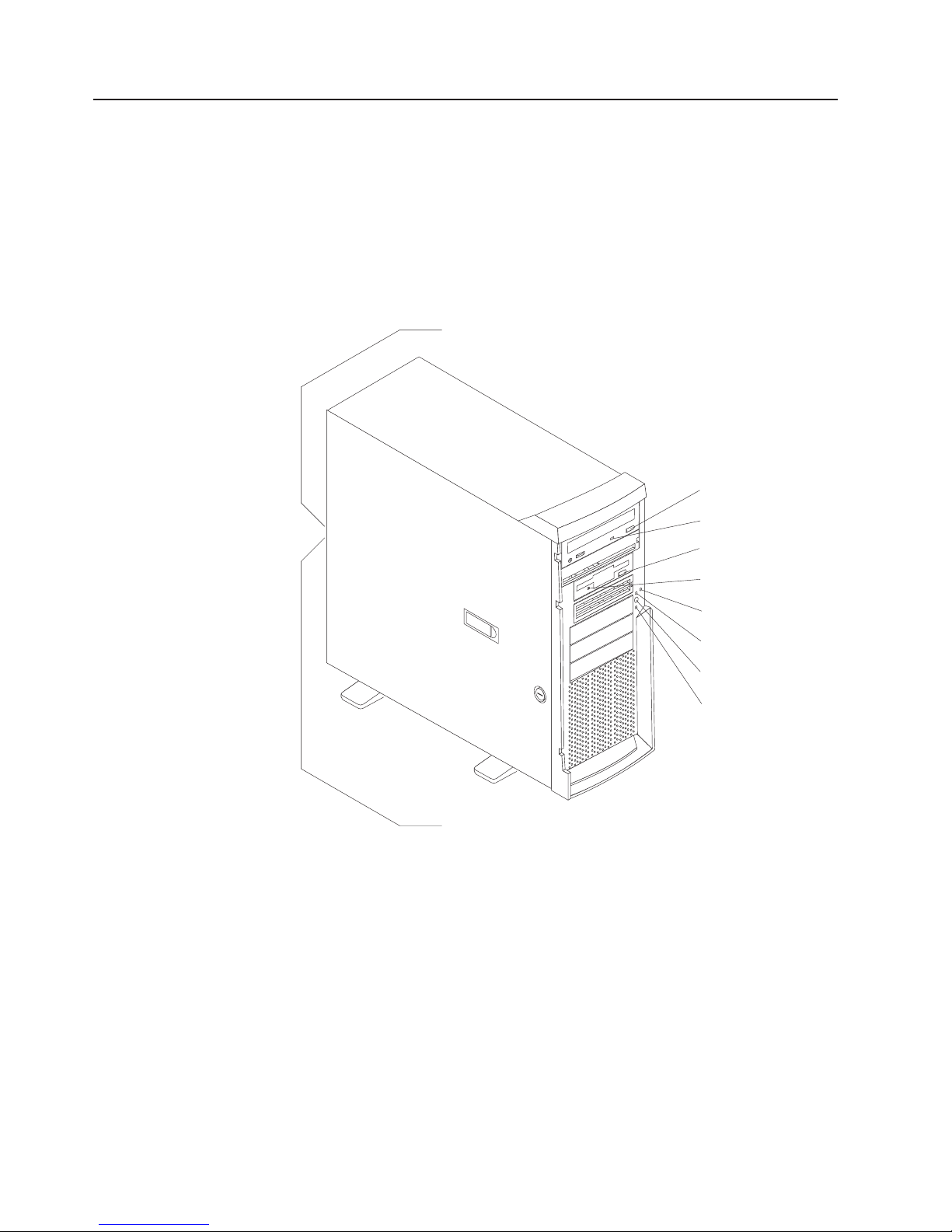
Server controls and LEDs
The following illustration shows the controls and LEDs on the server.
Note: The front bezel door is not shown so that the drive bays are visible.
Front View:
Ethernet speed 1 Gbps LED
CD-eject
button
CD-ROM drive
activity LED
Diskette-eject
button
Diskette drive
activity LED
Hard disk drive
activity LED
Power-on
LED
Power-control
button
System error
LED
Ethernet speed 1 Gbps LED: When this LED on the Ethernet connector is lit, it
indicates that the Ethernet network speed is 1 Gbps. When this LED is off, it
indicates that the Ethernet network speed is 10 Mbps or 100 Mbps.
CD-eject button: Press this button to release a CD from the CD-ROM drive.
CD-ROM drive activity LED: When this LED is lit, it indicates that the CD-ROM
drive is in use.
Diskette-eject button: Press this button to release a diskette from the diskette
drive.
Diskette drive activity LED: When this LED is lit, it indicates that the diskette drive
is in use.
4 IBM xSeries 205 Type 8480: Hardware Maintenance Manual and Troubleshooting Guide
Ethernet transmit/receive activity LED
Page 15
Hard disk drive activity LED: When this LED is flashing, it indicates that the hard
disk drive is in use.
Power-on LED: When this LED is lit, it indicates that the server is turned on.
Power-control button: Press this button to turn the server on and off manually.
Ethernet transmit/receive activity LED: When this LED on the Ethernet connector
is lit, it indicates that there is activity between the server and the network.
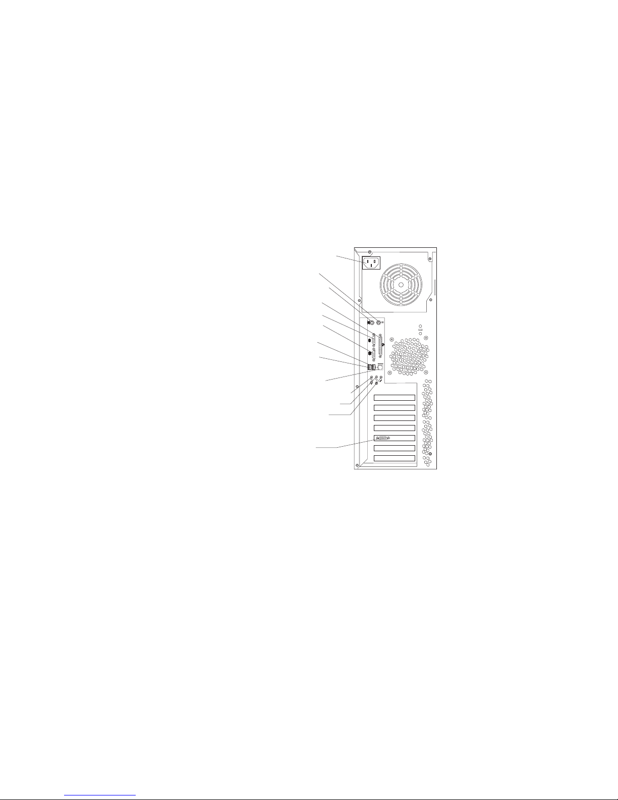
Server connectors
The following illustration shows the connectors on the rear of the server.
Rear View:
Power cord
Mouse
Keyboard
Parallel
Serial 1
Serial 2
USB 1
USB 2
Ethernet
Line out (green)
Line in (blue)
Mic (pink)
1
2
2
1
Video
Power-cord connector: Connect the power cord to this connector.
®
Mouse connector: Connect a mouse or other PS/2
device to this connector.
Keyboard connector: Connect a PS/2 keyboard to this connector.
Parallel connector: Connect a parallel device to this connector.
Serial 1 connector: Connect a 9-pin serial device to this connector.
Serial 2 connector: Connect a 9-pin serial device to this connector
USB 1 connector: Connect a USB device to this connector.
USB 2 connector: Connect a USB device to this connector.
Ethernet connector: Use this connector to connect the server to a network.
Mic connector (pink): Connect a microphone to this connector.
Chapter 1. General information 5
Page 16

Line out connector (green): Connect an audio output device, such as speakers, to
this connector.
Line in connector (blue): Connect an audio input device, such as a stereo, to this
connector.
Video connector: Connect a monitor to this connector.
If you have an optional Remote Supervisor Adapter (system-management adapter)
installed in PCI slot 1, your server has additional connectors and LEDs. See the
Option Installation Guide for more information about these connectors and LEDs.
Server power features
When you connect the server to an ac power source, the server goes into Standby
mode. After approximately 20 seconds, the power-control button becomes active,
and you can turn on the server and start the operating system by pressing the
power-control button. The following section describes other ways in which the
server can be turned on.
A power-control-button shield comes with your server. You can install this
disk-shaped shield to prevent the server from being turned off accidentally.
Turning on the server
After the server is connected to an ac power source, it can be turned on in any of
the following ways:
v You can press the power-control button.
v If a power failure occurs while the server is turned on, the server will restart
automatically when power is restored.
v If your operating system supports the system-management software for an
optional Remote Supervisor Adapter, the system-management software can turn
on the server.
v If your operating system supports the Wake on LAN
feature can turn on the server.
®
feature, the Wake on LAN
Turning off the server
Some operating systems require an orderly shutdown before you turn off the server.
See your operating-system documentation for information about shutting down the
operating system.
Statement 5:
6 IBM xSeries 205 Type 8480: Hardware Maintenance Manual and Troubleshooting Guide
Page 17
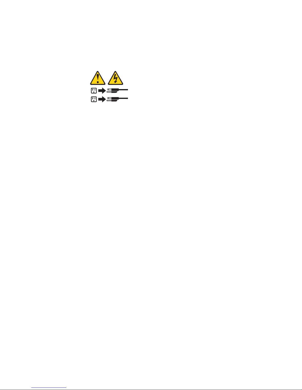
CAUTION:
The power control button on the device and the power switch on the power
supply do not turn off the electrical current supplied to the device. The device
also might have more than one power cord. To remove all electrical current
from the device, ensure that all power cords are disconnected from the power
source.
2
1
The server can be turned off in any of the following ways:
v You can press the power-control button to start an orderly shutdown of the
operating system, if your operating system supports this feature, and turn off the
server.
v If the operating system stops functioning, you can press and hold the
power-control button for more than 4 seconds to turn off the server.
v If the Wake on LAN feature turned on the server, the Wake on LAN feature can
turn off the server.
v You can remove all power from the computer by disconnecting the server from
the ac power source.
Standby mode
When the server is connected to an ac power source but has not been turned on, it
is in Standby mode. When the server is in Standby mode, the operating system is
not running, and all core logic except for the service processor is shut down. The
power-on LED flashes to indicate that the server is in Standby mode. The server
can respond to requests from the service processor, such as a remote request to
turn on the server.
To put the server into Standby mode when the server is turned on, shut down the
operating system (see your operating-system documentation), and press the
power-control button.
You can also put the server into Standby mode through a request from the service
processor.
Chapter 1. General information 7
Page 18

8 IBM xSeries 205 Type 8480: Hardware Maintenance Manual and Troubleshooting Guide
Page 19

Chapter 2. Configuring your server
You can use the following configuration programs to customize your server
hardware:
v Configuration/Setup Utility program
The Configuration/Setup Utility program is part of the basic input/output system
(BIOS) code that comes with your server. You can use this program to configure
serial port assignments, change interrupt request (IRQ) settings, change the
device startup sequence, set the date and time, and set passwords.
v Broadcom NetXtreme Gigabit Ethernet Boot Agent
The Broadcom NetXtreme Gigabit Ethernet Boot Agent is part of the BIOS code
that comes with your server. You can enable the Broadcom NetXtreme Gigabit
Ethernet Boot Agent in the Configuration/Setup Utility program. The Broadcom
NetXtreme Gigabit Ethernet Boot Agent enables you to configure the network as
a startable device and customize where the network option appears in your
startup sequence.
v ServerGuide Setup and Installation CD
The ServerGuide Setup and Installation CD provides software setup tools and
installation tools that are specifically designed for your IBM server. Use this CD
during the initial installation of your server to configure basic hardware features
and to simplify your network operating system (NOS) installation. See “Using the
ServerGuide Setup and Installation CD” on page 13 for more information.
v Ethernet controller configuration process
To configure the Ethernet controller, see “Configuring the Gigabit Ethernet
controller” on page 16.
v SCSISelect Utility program (some models)
If your server comes with a SCSI controller on the PCI extender card, you can
use the SCSISelect Utility program to configure devices that are attached to the
SCSI controller. Use this program to change default values, resolve configuration
conflicts, and perform a low-level format on a SCSI hard disk drive.
v Boot Menu program
The Boot Menu program is part of the BIOS code that comes with your server.
You can use the Boot Menu program to change startup sequence for one startup
session without changing settings in the Configuration/Setup Utility program.
Using the Configuration/Setup Utility program
This section provides the instructions for starting the Configuration/Setup Utility
program and descriptions of the menu choices that are available.
Starting the Configuration/Setup Utility program
The Configuration/Setup Utility program starts automatically when POST detects
that newly installed or removed hardware is not reflected in your current
configuration. A power-on-self-test (POST) error message is displayed. See the
Hardware Maintenance Manual and Troubleshooting Guide for details about the
POST error messages.
© Copyright IBM Corp. 2002 9
Page 20

Complete the following steps to start the Configuration/Setup Utility program:
1. Turn on the server and watch the monitor screen. If your server is already on
when you start this procedure, you must shut down the operating system, turn
off the server, wait a few seconds until all in-use LEDs go off, and restart the
server. Do not use Ctrl+Alt+Del to restart the server.
2. When the message Press F1 for Configuration/Setup, Press F12 for Boot
Menu appears at the bottom of the screen during startup, press F1. (This prompt
appears on the screen for only a few seconds. You must press F1 quickly.)
Note: If you have set both administrator and user passwords, you must type
the administrator password to access the full Configuration/Setup Utility
menu.
3. Follow the instructions that appear on the screen.
Use the Up Arrow (↑)and Down Arrow (↓) keys to select menu choices in any
Configuration/Setup Utility menu. Some menu choices provide information only.
Some menu choices show fields that you can change. These fields are enclosed by
square brackets. You can change the settings in these fields by using Left Arrow (←)
and Right Arrow (→) keys to change the settings, or you can type information in the
field.
To reload the current setting for a menu item, press F9. To reload the default setting
for a menu item, press F10.
Using passwords
The System Security choice appears only on the full Configuration/Setup Utility
menu. After you select this choice, you can implement an administrator password.
The administrator password provides access to all choices on the
Configuration/Setup Utility main menu. You can set, change, or delete the
administrator password.
The administrator password has the following features:
v No password is required to start the system.
v Type the password to access the Configuration/Setup Utility program.
v All choices are available on the Configuration/Setup Utility main menu.
Complete the following steps to set an administrator password:
1. From the Configuration/Setup Utility main menu, select System Security and
2. Select Administrator Password and press the Right Arrow (→) key.
3. Type the password you want to set in the Enter Password field and press
4. Type the password again in the Enter Password again field and press Enter.
5. Press Enter to Set or Change Password. The setting in the Administrator
6. Press Esc until you return to the main menu.
7. Select Save Settings and Press Enter.
press Enter.
Enter.
Password field changes to Present.
After you have set an administrator password, you can then set a user password to
authorize a user to operate the server. You must set an administrator password to
set a user password.
10 IBM xSeries 205 Type 8480: Hardware Maintenance Manual and Troubleshooting Guide
Page 21

You can use any combination of up to seven characters (A Z, a z, 0 9, and blanks)
for your user password. Keep a record of your password in a secure place. If you
forget the user password, you can regain access to the server through one of the
following methods:
v Type the administrator password at the power-on prompt. Start the
Configuration/Setup Utility program and change the user password.
v Change the position of the password check jumper (JP1) as described in “Setting
the password check jumper” on page 12.
v Remove the battery and then install the battery. See the Hardware Maintenance
Manual and Troubleshooting Guide for instructions.
To set a user password, complete the following steps:
1. Set an administrator password. See the instructions on page 10.
2. Select User Password and press the Right Arrow (→) key.
3. Type the password you want to set in the Enter Password field and press
Enter.
4. Type the password again in the Enter Password Again field and press Enter.
5. Press Enter to Set or Change Password. The setting in the User Password
field changes to Present.
6. Select Save Settings and press Enter.
If you set a user password, you can then enable Password on Boot. If you enable
this setting, you must type a user password when you start the server.
Chapter 2. Configuring your server 11
Page 22
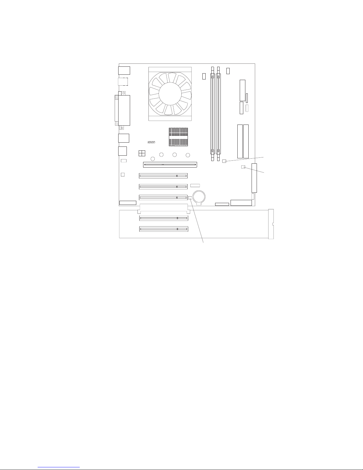
Setting the password check jumper
The following illustration shows the location of the password check jumper (JP1) on
the system board.
Password check
(JP1)jumper
CMOS clear
(JP3)jumper
Boot block
jumper (JP6)
Complete the following steps to set the password check jumper:
1. Review the “Safety information” on page 117.
2. Turn off the server and peripheral devices and disconnect all external cables
and power cords; then, remove the cover. See the Option Installation Guide for
instructions.
3. Move the jumper from pins 1 and 2 to pins 2 and 3. This clears the power-on
password for one boot cycle.
You can now start the server one time without having to use the user password,
but if you do not use the Configuration/Setup Utility program to change or delete
the password, the next time you start the server, the original power-on password
will be reinstated.
4. Connect the server to a power source, keyboard, monitor, and mouse.
5. Turn on the server.
You can now start the Configuration/Setup Utility program and either delete the old
password or set a new user password.
12 IBM xSeries 205 Type 8480: Hardware Maintenance Manual and Troubleshooting Guide
Page 23

Enabling Broadcom NetXtreme Gigabit Ethernet Boot Agent
The Broadcom NetXtreme Gigabit Ethernet Boot Agent is part of the BIOS code
that comes with your server. You can enable the Broadcom NetXtreme Gigabit
Ethernet Boot Agent in the Configuration/Setup Utility program. The Broadcom
NetXtreme Gigabit Ethernet Boot Agent enables you to configure the network as a
startable device and customize where the network appears in your startup order.
To enable Broadcom NetXtreme Gigabit Ethernet Boot Agent, complete the
following steps:
1. From the Configuration/Setup Utility main menu, select Devices and I/O Ports
and press Enter.
2. Select System Board Ethernet PXE/DHCP and use the Right Arrow (→) key to
set it to Enabled.
3. Select Save Settings and press Enter.
Using the ServerGuide Setup and Installation CD
The ServerGuide Setup and Installation CD includes an easy-to-use setup and
installation program that is specifically designed for your server. The ServerGuide
program detects the server model and hardware options that are installed and uses
that information during setup to configure the hardware. The ServerGuide program
simplifies operating-system installations by providing updated device drivers and, in
some cases, installing them automatically.
If a later version of the ServerGuide program is available, you can download a free
image of the ServerGuide Setup and Installation CD, or you can purchase the CD.
To download the latest ServerGuide program, go to the IBM ServerGuide Web page
at http://www.ibm.com/pc/qtechinfo/MIGR-4ZKPPT.html. To purchase the latest
ServerGuide Setup and Installation CD, see the “ServerGuide Updates” flyer that
comes with your server library, or go to the ServerGuide fulfillment Web site at
http://www.ibm.com/pc/coupon/.
The ServerGuide program has the following features to make setup easier:
v An easy-to-use interface with online help
v Diskette-free setup, and configuration programs that are based on detected
hardware
v Performance Optimizer program, which easily tunes your SCSI RAID adapter
settings for your server environment
v A system BIOS update program, which updates the BIOS code directly from the
CD
v Device drivers that are provided for your server model and detected hardware
ServerGuide features
Features and functions can vary slightly with different versions of the ServerGuide
program. To learn more about the version that you have, start the ServerGuide
Setup and Installation CD and view the online overview. Not all features are
supported on all server models.
The ServerGuide program requires a supported IBM server with an enabled
startable (bootable) CD-ROM drive. In addition to the ServerGuide Setup and
Installation CD, you must have your operating-system CD to install your operating
system.
Chapter 2. Configuring your server 13
Page 24

The ServerGuide program has the following features:
v Sets system date and time.
v Detects the SCSI RAID adapter or controller and runs the SCSI RAID
configuration program.
v Updates the licensed internal code (firmware) level without diskettes.
v Checks the system BIOS code and microcode (firmware) levels of supported
options to determine whether a later level is available from the CD. You can
perform updates without using diskettes.
v Provides the Performance Optimizer program to easily tune your SCSI RAID
adapter settings for your server environment.
v Detects installed hardware options and provides updated device drivers for most
adapters and devices.
v Creates a setup-replication diskette for replicating setup selections for other
servers of the same model.
v Provides diskette-free installation for supported operating systems.
v Provides a replicated installation path for multiple installations of supported
operating systems.
v Includes an online README file with links to tips for your hardware and
operating-system installation.
Setup and configuration overview
When you use the ServerGuide Setup and Installation CD, you do not need setup
diskettes. You can use the CD to configure any supported IBM server model. The
ServerGuide program checks your system BIOS, service processors, and other
system hardware to determine if system updates are available. The setup program
provides a list of tasks that are required to set up your server model. On SCSI
RAID servers, you can run the SCSI RAID configuration program to create logical
drives.
Note: Features and functions can vary slightly with different versions of the
ServerGuide program.
When you start the ServerGuide Setup and Installation CD, the program performs
the following tasks:
v The ServerGuide program prompts you for your language, country, and keyboard
layout. (This information is stored and later passed to the operating-system
installation program.)
v The ServerGuide program displays choices for running the configuration
programs. For example:
– The Express Configuration method runs the required programs for your
server, based on the hardware that is detected.
– The Custom Configuration method displays all programs that are available for
your server, and you decide which programs to run.
– The Replicated Configuration method provides the option of duplicating your
setup selections to other servers that are the same model.
v If you select the Custom Configuration method, the following features are
optional. If you select the Express Configuration method, some or all of these
features are run, depending on the hardware that is detected:
– The Set Date and Time feature is provided so that you do not have to use the
Configuration/Setup Utility program to access these settings.
14 IBM xSeries 205 Type 8480: Hardware Maintenance Manual and Troubleshooting Guide
Page 25

– The Clear Hard Disks feature is provided so you can delete all partitions on all
hard disk drives. If the server has a SCSI RAID adapter installed, you can
select to restore the configuration on the SCSI RAID adapter to the factory
default settings.
– The ServerGuide program checks the system BIOS code and microcode
(firmware) levels for supported options and then checks the CD for a newer
level. The CD content might be newer than the BIOS code and firmware level.
The ServerGuide program can perform a flash update of the BIOS code and
supported microcode (firmware) options without using diskettes.
– The SCSI RAID configuration program starts, leading you through the entire
configuration process.
– The Performance Optimizer program easily tunes your server for your
environment.
v The ServerGuide program displays a confirmation summary, so that you will
know when you have completed all the required tasks. Then, you are ready to
install your operating system.
Notes:
1. Plug and Play adapters are configured automatically. Non-Plug and Play
adapters might require switch settings, additional device drivers, and installation
after the operating system is installed. See the documentation that comes with
the adapter.
2. Diagnostics for your server come in BIOS code or on a separate diagnostics
CD.
Typical operating-system installation
You can use the ServerGuide program to shorten your installation time. The
ServerGuide program provides the device drivers that are required for your
hardware and for the operating system that you are installing. This section
describes a typical ServerGuide operating-system installation.
Note: Features and functions can vary slightly with different versions of the
ServerGuide program.
1. After you have completed the setup process, the operating-system installation
program starts. (You will need your operating-system CD to complete the
installation.)
2. The ServerGuide program stores information about the server model, service
processor, hard disk drive controllers, and network adapters. Then, the program
checks the CD for newer device drivers. This information is stored and then
passed to the operating-system installation program.
3. With some operating-system installations, you can create an
operating-system-replication diskette for setting up additional servers. This
diskette contains the Internet protocol (IP) address, server name, and other
selections.
4. If you are installing the operating system from diskette, the ServerGuide
program lists the diskettes that you must create and the optional diskettes that
you might want to create. The diskettes that you can create are the
device-driver diskettes for the installed adapters or controllers.
5. The ServerGuide program prompts you to insert your operating-system CD and
restart the server. At this point, the installation program for the operating system
takes control to complete the installation.
Chapter 2. Configuring your server 15
Page 26

Setting up or updating multiple servers
You can use the ServerGuide program to create diskettes that help you set up or
update multiple servers. You can modify information on the diskettes as you use
them to set up or update other servers.
Note: Availability and function can vary by server model and by the hardware that
is installed.
You can create a setup-replication diskette, which contains your hardware
configuration selections. Use this diskette to replicate selections to other servers
that are of the same model.
You can create an operating-system-replication diskette, which contains information
that you need to complete multiple installations. Not all operating systems support
operating-system-replication diskettes.
Installing your operating system without ServerGuide
If you have already configured the server hardware and you decide not to use the
ServerGuide program to install your operating system, complete the following steps
to download the latest operating-system installation instructions from the IBM
Support Web page:
1. Go to http://www.ibm.com/pc/support/.
2. Under Browse, click Servers.
3. From the Family drop-down list, select your server model.
4. If NOS installation instructions are available for your server model, OS
installation is in the list in the upper-left corner of the Web page. Click OS
installation and select the instructions for your operating system.
Configuring the Gigabit Ethernet controller
The server comes with an integrated Ethernet controller. This controller provides an
interface for connecting to 10-Mbps, 100-Mbps, or 1000-Mbps networks and
provides full duplex (FDX) capability, which enables simultaneous transmission and
reception of data on the Ethernet local area network (LAN). You do not need to set
any jumpers or configure the Ethernet controller for your operating system before
you use the Ethernet controller. However, you must install a device driver to enable
your operating system to address the Ethernet controller. The device drivers are
provided on the Device Drivers and IBM Enhanced Diagnostics CD.
When you connect your server to the network, the Ethernet controller automatically
detects the data-transfer rate (10-Mbps, 100-Mbps, or 1000-Mbps) on the network
and then sets the controller to operate at the appropriate rate. In addition, if the
Ethernet ports that your server is connected to support auto-negotiation, the Gigabit
Ethernet controller will set the appropriate duplex state. That is, the Ethernet
controller will adjust to the network data rate, whether the data rate is standard
Ethernet (10BASE-T), Fast Ethernet (100BASE-TX/1000BASE-T), half duplex
(HDX), or full duplex (FDX). The controller supports half-duplex (HDX) and
full-duplex (FDX) modes at both speeds.
For information about configuring your Ethernet controller, see the Device Drivers
and IBM Enhanced Diagnostics CD that comes with your server. For updated
information about configuring your Ethernet controller, go to the IBM Support Web
site at http://www.ibm.com/pc/support/ and navigate to the area for your specific
server type. From this area you can download documentation, the most current
16 IBM xSeries 205 Type 8480: Hardware Maintenance Manual and Troubleshooting Guide
Page 27

device drivers for your server, and software that supports advanced networking
functions. After downloading, run the downloaded program launch.exe.
You Ethernet controller supports optional modes, such as teaming, priority packets,
load balancing, fault tolerance, and virtual LANs, which provide higher performance,
security, and throughput for your server. These modes apply to the integrated
Ethernet controller and to the controllers on supported Ethernet adapters.
Using the SCSISelect Utility program
SCSISelect is a menu-driven configuration utility program for servers that come with
a SCSI adapter installed. You can use SCSISelect to:
v View the default SCSI IDs
v Locate and correct configuration conflicts
v Perform a low-level format on a SCSI hard disk
The following sections provide instructions for starting the SCSISelect Utility
program and descriptions of the menu choices available.
Starting the SCSISelect Utility program
Complete the following steps to start the SCSISelect utility program:
1. Turn on the server.
2. When the <<< Press <CTRL><A> for SCSISelect Utility! >>> prompt appears,
press Ctrl+A.
Note: If an administrator password has been set, you are prompted to type the
password to start the SCSISelect Utility program.
3. When the Would you like to configure the host adapter or run the SCSI
disk utility? question appears, make your selection and press Enter.
4. Use the arrow keys to select a choice from the menu.
5. Follow the instructions on the screen to change the settings of the selected
items, and press Enter.
Chapter 2. Configuring your server 17
Page 28

SCSISelect menu choices
The following choices appear on the SCSISelect Utility menu:
v Configure/View Host Adapter Settings
Select this choice to view or change the SCSI controller settings. To reset the
SCSI controller to its default values, press F6; then, follow the instructions that
appear on the screen.
You can view or change the following controller settings:
– Host Adapter SCSI ID
Select this choice to view the SCSI controller ID, normally 7.
– SCSI Parity Checking
This choice is set to Enabled and cannot be changed.
– Host Adapter SCSI Termination
This choice is set to Enabled and cannot be changed.
– Boot Device Options
Select this choice to configure startable device parameters. Before you can
make updates, you must know the ID of the device for which you want to
configure parameters.
– SCSI Device Configuration
Select this choice to configure SCSI device parameters. Before you can make
updates, you must know the ID of the device whose parameters you want to
configure.
Note: The Maximum Sync Transfer Rate represents the transfer rate for Ultra
SCSI devices.
- The transfer rate for Ultra3 SCSI LVD devices is 160 MBps.
- The transfer rate for Ultra2 SCSI LVD devices is 80 MBps.
- The transfer rate for Fast SCSI devices is 20 MBps.
– Advanced Configuration Options
Select this choice to view or change the settings for advanced configuration
options.
v SCSI Disk Utilities
Select this choice to view the SCSI IDs that are assigned to each device or to
format a SCSI device.
To use the utility program, select a drive from the list. Read the screens carefully
before making a selection.
Note: If you press Ctrl+A before the selected drives are ready, an Unexpected
SCSI Command Failure screen might appear. Restart the server and
watch the SCSISelect messages as each drive spins up. After the drive
that you want to view or format spins up, press Ctrl+A.
Using the Boot Menu program
The Boot Menu program is a built-in, menu-driven configuration utility program that
you can use to temporarily redefine the first startup device without changing
settings in the Configuration/Setup Utility program.
18 IBM xSeries 205 Type 8480: Hardware Maintenance Manual and Troubleshooting Guide
Page 29

Complete the following steps to use the Boot Menu program to change the startup
sequence of your server:
1. Turn off the server.
2. Restart the server.
3. Press F12.
4. Select the startup device.
The next time the server is started, it returns to the startup sequence set in the
Configuration/Setup Utility program.
Chapter 2. Configuring your server 19
Page 30

20 IBM xSeries 205 Type 8480: Hardware Maintenance Manual and Troubleshooting Guide
Page 31

Chapter 3. Diagnostics
This section provides basic troubleshooting information to help you resolve some
common problems that might occur with your server.
If you cannot locate and correct the problem using the information in this section,
see Appendix A, “Getting help and technical assistance”, on page 115 for more
information.
General checkout
The server diagnostic programs are stored on the IBM Enhanced Diagnostics CD.
These programs provide the primary methods of testing the major components of
the server.
If you cannot determine whether a problem is caused by the hardware or by the
software, you can run the diagnostic programs to confirm that the hardware is
working properly.
When you run the diagnostic programs, a single problem might cause several error
messages. When this occurs, work to correct the cause of the first error message.
After the cause of the first error message is corrected, the other error messages
might not occur the next time you run the test.
A failed system might be part of a shared DASD cluster (two or more systems
sharing one or more external storage devices). Before you run diagnostics, verify
that the failing system is not part of a shared DASD cluster.
A system might be part of a cluster if:
v The system is identified as part of a cluster.
v One or more external storage units are attached to the system and at least one
of the attached storage units is also attached to another system or unidentifiable
source.
v One or more systems are located near the failing system.
If the failing system is suspected to be part of a shared DASD cluster, you can run
all diagnostic tests except the diagnostic tests that test the storage unit (DASD
residing in the storage unit) or the storage adapter attached to the storage unit.
Notes:
1. For systems that are part of a shared DASD cluster, run one test at a time in
looped mode. Do not run all tests in looped mode, because this could enable
the DASD diagnostic tests.
2. If multiple error codes are displayed, diagnose the first error code that is
displayed.
3. If the computer stops with a POST error, go to “POST error codes” on page 95.
4. If the computer stops and no error is displayed, go to “Undetermined problems”
on page 106.
5. For power supply problems, see “Power checkout” on page 29.
6. For safety information, see “Safety information” on page 117.
7. For intermittent problems, check the error log.
© Copyright IBM Corp. 2002 21
Page 32

Checkout procedure
Follow the steps in this procedure to identify system problems.
001 IS THE SYSTEM PART OF A CLUSTER?
002 IF THE SYSTEM IS NOT PART OF A CLUSTER:
003 DID YOU RECEIVE BOTH OF THE CORRECT RESPONSES?
YES. Schedule maintenance for the system. Shut down all systems related
to the cluster. Run the storage test.
NO. Go to step 002.
1. Turn off the server and all external devices.
2. Check all cables and power cords.
3. Set all display controls to the middle position.
4. Turn on all external devices.
5. Turn on the server.
6. Record any POST error messages that are displayed on the screen. If
an error is displayed, look up the first error in the “POST error codes” on
page 95.
7. Check the System Error log. If an error was recorded by the system,
see Chapter 6, “Symptom-to-FRU index”, on page 85.
8. Start the diagnostic programs.
9. Check for the following responses:
v One beep.
v Readable instructions or the main menu.
NO. Find the failure symptom in Chapter 6, “Symptom-to-FRU index”, on
page 85.
YES. Run the diagnostic programs. If necessary, see “Diagnostic programs
and error messages” on page 25.
If you receive an error, see Chapter 6, “Symptom-to-FRU index”, on
page 85.
If the diagnostic programs were completed successfully and you still
suspect a problem, see “Undetermined problems” on page 106.
22 IBM xSeries 205 Type 8480: Hardware Maintenance Manual and Troubleshooting Guide
Page 33

Diagnostic tools overview
The following tools are available to help you identify and resolve hardware-related
problems:
v POST beep codes and error messages
The power-on self-test (POST) generates beep codes and messages to indicate
successful test completion or the detection of a problem. See “POST” for more
information.
v Error log
The POST error log contains the three most recent error codes and messages
that the system has generated during POST. The System Error Log contains all
the error messages that were issued during POST.
To view the contents of the error logs, start the Configuration/Setup Utility
program; then, select Error Logs from the main menu. See “Viewing the System
Error log” on page 28 for more information.
v ServerGuide error symptoms
ServerGuide error symptoms are explained at “ServerGuide error symptoms” on
page 24.
v Diagnostic programs and error messages
The server diagnostic programs are stored on the IBM Enhanced Diagnostics
CD. These programs are the primary method of testing the major components of
your server. See “Diagnostic programs and error messages” on page 25 for more
information.
v Customized support page
You can create a customized support page that is specific to your hardware,
complete with Frequently Asked Questions, Parts Information, Technical Hints
and Tips, and Downloadable files. In addition, you can choose to receive
electronic mail (e-mail) notifications whenever new information becomes available
about your registered products.
After you register and profile your xSeries products, you can diagnose problems
using the IBM Online Assistant, and you can participate in the IBM discussion
forum. For more detailed information about registering and creating a customized
profile for your IBM products, go to the following addresses on the Web:
– http://www.ibm.com/pc/register
– http://www.ibm.com/pc/support
POST
When you turn on the server, it performs a series of tests to check the operation of
server components and some of the options installed in the server. This series of
tests is called the power-on self-test, or POST.
Notes:
1. If you have a user password or administrator password set, you must type the
password and press Enter, when prompted, before POST will continue.
2. A single problem might cause several error messages. When this occurs, work
to correct the cause of the first error message. After you correct the cause of
the first error message, the other error messages usually will not occur the next
time you run the test.
Chapter 3. Diagnostics 23
Page 34

POST beep codes
POST generates beep codes to indicate successful completion or the detection of a
problem.
v One short beep indicates the successful completion of POST.
v More than one beep indicates that POST detected a problem. For more
If POST detects a problem (more than one beep sounds), an error message
appears on your screen. See “Beep symptoms” on page 85 and “POST error codes”
on page 95 for more information.
Error logs
A POST error log is available when an optional service processor adapter has been
installed in the server.
The POST error log contains the three most recent error codes and messages that
the system generated during POST. The System Error log contains all messages
issued during POST and all system status messages from the service processor.
You can view the contents of the System Error log from the Configuration/Setup
Utility program or from the diagnostic programs.
Viewing error logs from the Configuration/Setup Utility program
Start the Configuration/Setup Utility program; then, select Error Logs from the main
menu. See Chapter 2, “Configuring your server”, on page 9 for more information.
information, see “Beep symptoms” on page 85.
Viewing error logs from diagnostic programs
Start the diagnostic programs; select Hardware Info from the top of the diagnostic
programs screen; select System Error Log from the list that appears; then, follow
the instructions on the screen. See “Starting the diagnostic programs” on page 26
for more information.
ServerGuide error symptoms
Look for the symptom in the left column of the chart. Probable solutions to the
problem are in the right column.
Table 1. ServerGuide Setup and Installation CD
Symptom Suggested action
The ServerGuide
Setup and
Installation CD will
not start.
The SCSI RAID
program cannot
view all installed
drives, or the NOS
cannot be installed.
The Operating
System Installation
program
continuously loops.
v Ensure that the server is supported and has a startable (bootable)
CD-ROM drive.
v If the startup (boot) sequence settings have been altered, ensure
that the CD-ROM drive is first in the startup sequence.
v If more than one CD-ROM drive is installed, ensure that only one
drive is set as the primary drive. Start the CD from the primary
drive.
v Ensure that there are no duplicate SCSI IDs or IRQ assignments.
v Ensure that the hard disk drive is connected properly.
Make more space available on the hard disk.
24 IBM xSeries 205 Type 8480: Hardware Maintenance Manual and Troubleshooting Guide
Page 35

Table 1. ServerGuide Setup and Installation CD (continued)
Symptom Suggested action
The ServerGuide
program will not
start your NOS CD.
The NOS cannot
be installed; the
option is not
available.
Ensure that the NOS CD you have is supported by the ServerGuide
program. See the ServerGuide Setup and Installation CD label for a
list of supported NOS versions.
Ensure that the NOS is supported on your server. If the NOS is
supported, either there is no logical drive defined (SCSI RAID
systems) or the ServerGuide System Partition is not present. Run the
ServerGuide program, and ensure that setup is complete.
Small computer system interface messages
If you receive a SCSI error message, see “Diagnostic error codes” on page 89.
Note: If your server does not have a hard disk drive, ignore any message that
indicates that the BIOS is not installed.
Diagnostic programs and error messages
The server diagnostic programs are stored on the IBM Enhanced Diagnostics CD.
These programs are the primary method of testing the major components of your
server.
Diagnostic error messages indicate that a problem exists; they are not intended to
be used to identify a failing part. Troubleshooting and servicing of complex
problems that are indicated by error messages should be performed by trained
service personnel.
Sometimes the first error to occur causes additional errors. In this case, the server
displays more than one error message. Always follow the suggested action
instructions for the first error message that appears.
The following sections contain the error codes that might appear in the detailed test
log and summary log when the diagnostic programs are run.
The error code format is as follows:
fff-ttt-iii-date-cc-text message
where:
fff is the three-digit function code that indicates the function being
tested when the error occurred. For example, function code 089 is
for the microprocessor.
ttt is the three-digit failure code that indicates the exact test failure that
was encountered. (These codes are for trained service personnel;
see “Diagnostic error codes” on page 89).
iii is the three-digit device ID. (These codes are for trained service
personnel; see “Diagnostic error codes” on page 89).
date is the date that the diagnostic test was run and the error recorded.
cc is the check value that is used to verify the validity of the
text message is the diagnostic message that indicates the reason for the problem.
information.
Chapter 3. Diagnostics 25
Page 36

Text messages
The diagnostic text message format is as follows:
Function Name: Result (test specific string)
where:
Function Name
is the name of the function being tested when the error occurred. This
corresponds to the function code (fff) shown in the error code format in the
previous section.
Result
can be one of the following:
Passed This result occurs when the diagnostic test
is completed without any errors.
Failed This result occurs when the diagnostic test
discovers an error.
User Aborted This result occurs when you stop the
diagnostic test before it is complete.
Not Applicable This result occurs when you specify a
diagnostic test for a device that is not
present.
Aborted This result occurs when the test could not
proceed, for example, because of the
system configuration.
Warning This result occurs when a possible problem
test specific string
is additional information that you can use to analyze the problem.
Starting the diagnostic programs
The IBM Enhanced Diagnostics programs will isolate your server hardware from
software that you have installed on your hard disk drive. The programs run
independently of the operating system, and must be run either from the CD or
diskette. This method of testing is generally used when other methods are not
accessible or have not been successful in isolating a problem suspected to be
hardware related.
An IBM Enhanced Diagnostics CD comes with the server. You can also download
the latest image of the diagnostics from the World Wide Web at
http://www.ibm.com/pc/support.
Note: When using diagnostics with a USB Keyboard and Mouse attached, go into
Setup and enable USB emulation.
1. Press F1 Config/Setup
2. Select Devices and I/O Ports
3. Select USB Setup
4. Make sure USB Keyboard and Mouse are enabled.
is reported during the diagnostic test, such
as when a device driver is not found.
26 IBM xSeries 205 Type 8480: Hardware Maintenance Manual and Troubleshooting Guide
Page 37

Using the diagnostics CD
To start the IBM Enhanced Diagnostics using the CD, do the following:
1. Turn off your server and any peripheral devices.
2. Turn on all attached devices; then, turn your server on.
3. When you see Press F1 For Configuration/Setup, press the F1 key.
4. When the Configuration/Setup Utility menu appears, select Start Options.
5. From the Start Options menu, select Startup Sequence.
6. Note the device selected as the First Startup Device. Later, you must restore
this setting.
7. Select CD-ROM as the First Startup Device.
8. Press Esc two times to return to the Configuration/Setup Utility menu.
9. Place the IBM Enhanced Diagnostics CD in the CD-ROM drive.
10. Select Save & Exit Setup and follow the prompts. The diagnostics will load.
Follow the instructions on the screen to run the diagnostics.
Important: When you finish running the diagnostics and utilities, remove the
CD from the CD-ROM drive and turn off the server. You must
restore the First Startup Device to the original setting. Use steps 2
through 8 of this procedure to do this.
Downloading the diagnostics program
Do the following to download the latest image of the IBM Enhanced Diagnostics
from the World Wide Web and create a startable Enhanced Diagnostics diskette:
1. Go to the following World Wide Web site: http://www.ibm.com/pc/support/
2. Download the diagnostics file for your server to a hard disk drive directory (not
to a diskette).
3. Go to a DOS prompt and change to the directory where the file was
downloaded.
4. Insert a blank high-density diskette in diskette drive A.
5. Type in the following, and then press Enter: filename a: where filename is the
name of the file you downloaded from the Web.
The downloaded file is self-extracting and will be copied to the diskette. When the
copy completes, you have a startable IBM Enhanced Diagnostics diskette.
Using the diagnostic diskette
Do the following to start the IBM Enhanced Diagnostics using the diagnostics
diskette, do the following:
1. Turn off your server and any peripheral devices.
2. Insert the IBM Enhanced Diagnostics diskette into the diskette drive.
3. Turn on all attached devices; then, turn on the server.
4. Follow the instructions on the screen.
5. Place the IBM Enhanced Diagnostics CD in the CD-ROM drive. The diagnostics
will load. Follow the instructions on the screen to run the diagnostics.
When the tests have completed, you can view the Test Log by selecting Utility from
the top of the screen.
If the hardware checks out OK but the problem persists during normal server
operations, a software error might be the cause. If you suspect a software problem,
refer to the information that comes with the software package.
Chapter 3. Diagnostics 27
Page 38

Viewing the test log
The test log records data about system failures and other pertinent information. The
test log will not contain any information until after the diagnostic program has run.
Note: If you already are running the diagnostic programs, begin with step 4
1. Insert the IBM Enhanced Diagnostics CD.
2. Turn on the system and watch the screen.
If the system is on, shut down your operating system and restart the system.
3. If a power-on password is set, the system prompts you for it. Type in the
appropriate password; then, press Enter.
4. Run the appropriate diagnostics program and when the Diagnostic Programs
screen appears, select Utility.
5. Select View Test Log from the list that appears; then, follow the instructions on
the screen.
6. You can save the test log to a file on a diskette or to your hard disk drive.
Note: The system maintains the test-log data while the system is powered on.
When you turn off the power to the server, the test log is cleared.
Viewing the System Error log
With the optional service processor adapter, you can also view the System Error log
from the diagnostic programs. See the instructions in “POST” on page 23.
Diagnostic error message tables
For descriptions of the error messages that might appear when you run the
diagnostic programs, see “Diagnostic error codes” on page 89.
Notes:
1. Depending on your server configuration, some of the error messages might not
appear when you run the diagnostic programs.
2. If diagnostic error messages appear that are not listed in the tables, make sure
that your server has the latest levels of BIOS, Advanced System Management
Processor, ServeRAID
™
, and diagnostics microcode installed.
28 IBM xSeries 205 Type 8480: Hardware Maintenance Manual and Troubleshooting Guide
Page 39

Recovering from a POST/BIOS update failure
If power to your server is interrupted while POST/BIOS is being updated (flash
update), your server might not restart correctly. If this happens, perform the
following procedure:
1. Turn off the server and all attached devices.
2. Unplug all power cords from electrical outlets and remove the server cover and
the support bracket. See the Option Installation Guide for instructions.
3. Locate the boot block and password check jumpers on the system board,
removing any adapters that impede access to the jumpers. See “System and
PCI extender boards” on page 35 for the location of the boot block and
password check jumpers.
4. Move the jumper to the adjacent pair of jumper pins.
5. Replace any adapters that were removed and replace the support bracket and
the cover. See the Option Installation Guide for instructions. Reconnect the
power cords for the server and monitor to electrical outlets.
6. Insert the POST/BIOS update (flash) diskette into drive A, and turn on the
server and monitor.
7. After the update session completes, remove the diskette from the diskette
drive, and turn off the server and monitor.
8. Unplug all power cords from electrical outlets, and remove the cover.
9. Remove any adapters that impede access to the boot block and password
check jumpers.
10. Replace the boot block and password check jumpers to their original positions.
11. Replace any adapters that were removed.
12. Replace the cover, and reconnect all cables that were disconnected.
13. Turn on the server to restart the operating system.
Power checkout
Power problems can be difficult to solve. For example, a short circuit can exist
anywhere on any of the power distribution buses. Usually a short circuit will cause
the power subsystem to shut down because of an overcurrent condition.
A general procedure for troubleshooting power problems is as follows:
1. Turn off the server and disconnect all ac power cords.
2. Check for loose cables in the power subsystem. Also check for short circuits, for
example, if there is a loose screw causing a short circuit on a circuit board.
3. Remove adapters and disconnect the cables and power connectors to all
internal and external devices until the server is at the minimum configuration
required to start the server (see “Minimum operating requirements” on page 95).
4. Reconnect all ac power cords and turn on the server. If the server starts up
successfully, replace adapters and devices one at a time until the problem is
isolated. If the server does not start up from the minimal configuration, replace
FRUs of minimal configuration one at a time until the problem is isolated.
To use this method, it is important to know the minimum configuration required for a
system to start (see page 95).
Chapter 3. Diagnostics 29
Page 40

Troubleshooting the Ethernet controller
This section provides troubleshooting information for problems that might occur with
the 10/100/1000 Mbps Ethernet controller.
Network connection problems
If the Ethernet controller cannot connect to the network, check the following
conditions:
v Make sure that the cable is installed correctly.
The network cable must be securely attached at all connections. If the cable is
attached but the problem remains, try a different cable.
If you set the Ethernet controller to operate at either 100 Mbps or 1000 Mbps,
you must use Category 5 or higher cabling.
v Determine whether the hub supports auto-negotiation. If it does not, try
configuring the integrated Ethernet controller manually to match the speed and
duplex mode of the hub.
v Check the Ethernet controller LEDs on the operator information panel and on the
rear of the server.
These LEDs indicate whether a problem exists with the connector, cable, or hub.
– The Ethernet transmit/receive activity LED, on the operator information panel,
is lit when the Ethernet controller sends or receives data over the Ethernet
Network. If the Ethernet transmit/receive activity LED is off, make sure that
the hub and network are operating and that the correct device drivers are
installed.
– The Ethernet link status LED, on the rear of the server, is lit when the
Ethernet controller receives a LINK pulse from the hub. If the LED is off, there
might be a defective connector or cable or a problem with the hub.
v Make sure that you are using the correct device drivers which are supplied with
your server.
v Check for operating-system-specific causes for the problem.
v Make sure that the device drivers on the client and server are using the same
protocol.
v Test the Ethernet controller.
The way the Ethernet controller is tested depends on which operating system
you are using (see the Ethernet controller device driver README files).
30 IBM xSeries 205 Type 8480: Hardware Maintenance Manual and Troubleshooting Guide
Page 41

Ethernet controller troubleshooting chart
Use the following troubleshooting chart to find solutions to 10/100/1000 Mbps
Ethernet controller problems that have definite symptoms.
Table 2. Ethernet troubleshooting chart
Ethernet controller
problem
The server stops
running when loading
device drivers.
Ethernet link status LED
does not work.
The Ethernet
transmit/receive activity
LED does not work.
Data is incorrect or
sporadic.
The Ethernet controller
stopped working when
another adapter was
added to the server.
The Ethernet controller
stopped working without
apparent cause.
FRU/actions
The PCI BIOS interrupt settings are incorrect.
Check the following:
v Determine if the interrupt (IRQ) setting assigned to the Ethernet controller is also
assigned to another device in the Configuration/Setup Utility program.
Although interrupt sharing is allowed for PCI devices, some devices do not function well
when they share an interrupt with a dissimilar PCI device. Try changing the IRQ
assigned to the Ethernet controller or the other device. For example, for NetWare
Versions 3 and 4, it is recommended that disk controllers not share interrupts with LAN
controllers.
v Make sure that you are using the most recent device driver available from the World
Wide Web.
v Reseat or replace the adapter.
Check the following:
v Make sure that the hub is turned on.
v Check all connections at the Ethernet controller and the hub.
v Use another port on the hub.
v If the hub does not support auto-negotiation, manually configure the Ethernet controller
to match the hub.
v If you manually configured the Duplex mode, make sure that you also manually
configure the speed.
v Reseat or replace the adapter.
Check the following:
v Make sure that you have loaded the network device drivers.
v The network might be idle. Try sending data from this server.
Check the following:
v Make sure that you are using Category 5 or higher cabling when operating the server at
100 Mbps or at 1000 Mbps.
v Make sure that the cables do not run close to noise-inducing sources like fluorescent
lights.
Check the following:
v Make sure that the cable is connected to the Ethernet controller.
v Make sure that your PCI system BIOS code is current.
v Reseat the adapter.
v Determine if the interrupt (IRQ) setting assigned to the Ethernet adapter is also assigned
to another device in the system. Use the Configuration/Setup Utility program to
determine if this is the case.
Although interrupt sharing is allowed for PCI devices, some devices do not function well
when they share an interrupt with a dissimilar PCI device. Try changing the IRQ
assigned to the Ethernet adapter or the other device.
v Reseat or replace the adapter.
Check the following:
v Try a different connector on the hub.
v Reinstall the device drivers. See your operating-system documentation and the
ServerGuide information.
v Reseat or replace the adapter.
Chapter 3. Diagnostics 31
Page 42

Ethernet controller messages
The integrated Ethernet controller might display messages from certain device
drivers. The latest information available concerning these messages will be made
available at the IBM Support Web site at http://www.ibm.com/pc/support.
32 IBM xSeries 205 Type 8480: Hardware Maintenance Manual and Troubleshooting Guide
Page 43

Chapter 4. Installing options
This section provides instructions for installing options in an IBM Eserver xSeries
205 Type 8480.
System reliability considerations
To help ensure proper system cooling and system reliability, make sure that:
v Each of the drive bays has a drive or a filler panel and electromagnetic
compatibility (EMC) shield installed.
v There is adequate space around the server to allow the server cooling system to
work properly. Leave approximately 51 mm (2 in.) of open space around the front
and rear of the server. Do not place objects in front of the fans.
v You have followed the instructions for cabling provided with optional adapters.
v You have replaced a failed fan as soon as possible.
© Copyright IBM Corp. 2002 33
Page 44

Major components of the IBM Eserver xSeries 205 Type 8480
The following illustration shows the locations of major components in the IBM
Eserver xSeries 205 Type 8480 server.
Note: The illustrations in this document might look slightly different from your
hardware.
Rear adapter-
Microprocessor
Memory modules
retaining bracket
PCI extender
board
Drive cage
Front adaptersupport bracket
EMC shields
Filler
panels
Cover
Frame-support bracket
34 IBM xSeries 205 Type 8480: Hardware Maintenance Manual and Troubleshooting Guide
Page 45

System and PCI extender boards
This illustration identifies parts of the system board and PCI extender board.
Depending on installed options, your system board and PCI extender board might
look slightly different.
Microprocessor
and fan (U6)
AGP
PCI 1
DIMM 2
DIMM 1
PCI 2
PCI 3
PCI 4
PCI 5
Battery
Chapter 4. Installing options 35
Page 46

System board internal cable connectors
The following illustration identifies system board connectors for internal cables.
Microprocessor fan
connector (CN3)
Rear fan
(CN19)
Microprocessor
power
Internal speaker
connector
Front fan
connector (CN2)
Main power
SCSI LED
connector
Primary IDE
(PRI IDE)
Secondary IDE
(SEC IDE)
Password check
(JP1)jumper
CMOS
clear jumper (JP3)
Diskette drive
Wake on LAN
connector
®
Video
connector
Boot block
jumper (JP6)
SCSI drive connector
36 IBM xSeries 205 Type 8480: Hardware Maintenance Manual and Troubleshooting Guide
Page 47

System board external connectors
The following illustration identifies system board connectors for external cables.
Keyboard
Mouse
Serial ports
Parallel
USB ports
Ethernet
Audio
Optional system-management adapter component locations
The following illustration shows the connectors and LEDs for the optional
system-management adapter that you can install in PCI slot 1 on the system board.
Ethernet link status
LED (green)
Ethernet activity
LED (green)
ASM Interconnect port
(RJ-14)
Error LED
(amber)
External power
supply connector
(not used)
-
P
P
Ethernet port
(RJ-45)
Serial port
(COM)
Power LED
(green)
P
P
Chapter 4. Installing options 37
Page 48

Installation guidelines
Before you begin to install options in your server, read the following information:
v Read the handling guidelines in “Handling static-sensitive devices”, and read the
safety statements in “Safety information” on page 117. These guidelines will help
you work safely with your server and options.
v Make sure that you have an adequate number of properly grounded electrical
outlets for your server, monitor, and other options that you intend to install.
v Back up all important data before you make changes to disk drives.
v Have a small, flat-blade screwdriver available.
v Before accessing the inside of the IBM Eserver xSeries 205 Type 8480 server,
rotate the two front stabilizing feet a quarter turn towards the server, so they do
not break. Before placing the server in an upright position, rotate the two front
feet a quarter turn outward from the server. See “Moving the stabilizing feet” on
page 39.
v For a list of supported options for your server, go to
http://www.ibm.com/pc/support/ on the World Wide Web.
System reliability considerations
To help ensure proper system cooling and system reliability, make sure that:
v Each of the drive bays has a drive or a filler panel and electromagnetic
compatibility (EMC) shield installed.
v There is adequate space around the server to allow the server cooling system to
work properly. Leave approximately 51 mm (2 in.) of open space around the front
and rear of the server. Do not place objects in front of the fans.
v You have followed the instructions for cabling provided with optional adapters.
v You have replaced a failed fan as soon as possible.
Handling static-sensitive devices
Attention: Static electricity can damage electronic devices and your system. To
avoid damage, keep static-sensitive devices in their static-protective packages until
you are ready to install them.
To reduce the possibility of electrostatic discharge, observe the following
precautions:
v Limit your movement. Movement can cause static electricity to build up around
you.
v Handle the device carefully, holding it by its edges or its frame.
v Do not touch solder joints, pins, or exposed printed circuitry.
v Do not leave the device where others can handle and possibly damage the
device.
v While the device is still in its static-protective package, touch it to an unpainted
metal part of the server for at least 2 seconds. (This drains static electricity from
the package and from your body.)
v Remove the device from its package and install it directly into the server without
setting it down. If it is necessary to set the device down, place it in its
static-protective package. Do not place the device on the server cover or on a
metal table.
v Take additional care when handling devices during cold weather because heating
reduces indoor humidity and increases static electricity.
38 IBM xSeries 205 Type 8480: Hardware Maintenance Manual and Troubleshooting Guide
Page 49

Moving the stabilizing feet
The four feet on the bottom of the server provide additional stability when the feet
are placed in the stabilizing position.
Complete the following steps to place the feet in the stabilizing position:
1. Place the server on its side.
2. Locate the release tab inside the foot; then, lift up on the tab.
Note: The following illustration shows the rear feet located on the bottom rear
of the server.
Feet (unlocked position)
Release tab
Release tab
3. Rotate the foot inward to the unlocked position; then, remove the foot from the
server.
Chapter 4. Installing options 39
Page 50

4. Align the post in the center of the foot with the hole on the bottom of the server
and place the foot between the guides as indicated.
Note: The following illustration shows the rear feet located on the bottom rear
of the server.
Guides
Feet (locked position)
Guides
5. Rotate the foot outward until the foot locks into place.
6. Complete steps 2 through 5 for each foot.
Attention: When you need to access the inside of the server to install options,
you might find it easier to lay the server on its side. If you do so, make sure the
feet are in the horizontal position (see the previous steps). Otherwise, the feet
might break off from the server because of the weight of the server.
Removing the side cover
Complete the following steps to remove the side cover of the server.
Note: To remove the side cover, you might find it easier to lay the server on its
side. If you do, move the stabilizing feet so that they do not break. See
“Moving the stabilizing feet” on page 39.
1. Review the information in “Installation guidelines” on page 38 and “Safety
information” on page 117.
2. Turn off the server and all attached devices.
3. Disconnect all external cables and power cords.
40 IBM xSeries 205 Type 8480: Hardware Maintenance Manual and Troubleshooting Guide
Page 51

4. Pull the cover-release latch away from the server, and push the side cover
toward the rear of the server.
Cover-release
latch
To replace the side cover, see “Replacing the side cover” on page 59.
Attention: For proper cooling and airflow, replace the side cover before turning on
the server. Operating the server with the side cover removed might damage server
components.
Removing the frame-support bracket
When working with some options, such as hard disk drives, adapters, and memory
modules, you must first remove the frame-support bracket to access the existing
option.
Key lock
Chapter 4. Installing options 41
Page 52

Complete the following steps to remove the frame-support bracket:
1. Pull out on the rear end of the frame-support bracket approximately 150 mm (6
in.).
2. Pull the rear end of the frame-support bracket away from the server and place
the bracket aside.
To reinstall the frame-support bracket, reverse the previous steps.
Working with adapters
Your server comes with five 32-bit, 33 MHz PCI adapter connectors or slots and
one AGP slot. You can install an AGP video adapter in the AGP slot.
See “System and PCI extender boards” on page 35 for the location of PCI
expansion slots on the system board and PCI extender board.
Adapter considerations
Before you install adapters, review the following:
v Follow the instructions that come with the adapter in addition to the instructions
in this chapter. If you need to change the switch or jumper settings on your
adapter, follow the instructions that come with the adapter.
v You can install full-length adapters in all five PCI slots.
v Your server supports 5.0 V and universal PCI adapters; it does not support 3.3 V
adapters.
42 IBM xSeries 205 Type 8480: Hardware Maintenance Manual and Troubleshooting Guide
Page 53

v Your server uses a rotational interrupt technique to configure PCI adapters.
Therefore, you can install a variety of PCI adapters that currently do not support
sharing of PCI interrupts.
v PCI slots 1 through 5 are on PCI bus 2.
The system scans the AGP slot and PCI expansion slots 1 through 5 to assign
system resources. Then, the system starts devices in the following order, if you
have not changed the default startup sequence: the AGP slot, PCI expansion
slots 1 and 2, system board integrated drive electronics (IDE) or SCSI devices,
and then PCI expansion slots 3 through 5.
v The optional Remote Supervisor Adapter must be installed in PCI slot 1.
v For a list of supported options for your server, go to
http://www.ibm.com/pc/support/ on the World Wide Web.
Installing an adapter
Complete the following steps to install an adapter.
Attention: When you handle static-sensitive devices, take precautions to avoid
damage from static electricity. For details about handling these devices, see
“Handling static-sensitive devices” on page 38.
1. Review the information in “Safety information” on page 117.
2. Turn off the server and all attached devices, and disconnect all external cables
and power cords; then, remove the side cover. See “Removing the side cover”
on page 40.
Note: Check the instructions that come with the adapter for any requirements,
restrictions, or cabling instructions. It might be easier to route any
cables before you install the adapter.
3. Remove the frame-support bracket. See “Removing the frame-support bracket”
on page 41.
4. If you are installing a full-length adapter, rotate the front adapter-retaining
bracket to the open position.
5. Rotate the rear adapter-retaining bracket to the open (unlocked) position, and
remove it from the server.
6. From the rear of the server, press on the slot cover. Grasp it and pull the
expansion-slot cover out of the expansion slot. Store it in a safe place for
future use.
Attention: Expansion-slot covers must be installed on all vacant slots. This
maintains the electronic emissions standards of the server and ensures proper
ventilation of server components.
7. Set any jumpers or switches on the adapter or system board as described by
the adapter manufacturer.
Chapter 4. Installing options 43
Page 54

8. Remove the adapter from the static-protective package, carefully grasp the
adapter by the top edge or upper corners, and align it with the expansion slot
guides; then, press the adapter firmly into the expansion slot.
Note: It is best to move the adapter directly from the static-protective package
to the adapter slot. If this is not possible, set the adapter down on its
static-protective package on a hard surface. Avoid touching the
components and gold-edge connectors on the adapter.
Attention: Be certain that the adapter is correctly seated in the expansion slot
before you turn on the server. Incomplete installation of an adapter might
damage the system board or the adapter.
Expansion-slot
cover
Rear adapterretaining
bracket
Adapter
Front adaptersupport bracket
9. Connect required cables to the adapter. Route cables so that they do not block
airflow from the fans.
10. If you have another adapter to install, repeat steps 1 through 10. If you have
another option to install, do so now.
11. If you have installed a full-length adapter, rotate the front adapter-retaining
bracket to the closed (locked) position.
12. Reinstall the rear adapter-retaining bracket; then, rotate the bracket to the
closed (locked) position.
Note: The rear adapter-retaining bracket rests against the side cover. You
might find it easier to lay the server on its side to replace the side
cover.
13. Replace the frame-support bracket.
14. Replace the side cover. See “Replacing the side cover” on page 59 for details.
15. Reconnect the external cables and power cords; then, turn on the attached
devices and the server.
44 IBM xSeries 205 Type 8480: Hardware Maintenance Manual and Troubleshooting Guide
Page 55

Installing a SCSI adapter
Complete the following steps to install a SCSI adapter:
1. Complete steps 1 through 9 of “Installing an adapter” on page 43.
2. Connect the SCSI signal cable to the adapter and one or more of the signal
cable connectors to the rear of the SCSI devices.
3. Connect the SCSI activity indicator cable to the adapter and to the SCSI LED
connector on the system board. See “System and PCI extender boards” on
page 35 for the location of the SCSI LED connector.
SCSI cable
RAID
adapter
SCSI connector
4. If you have other adapters or options to install or remove, do so now.
5. Rotate the front adapter-support bracket to the closed (locked) position.
6. Reinstall the rear adapter-support bracket; then, rotate it to the closed (locked)
position.
7. Replace the frame-support bracket.
8. Replace the side cover. See “Replacing the side cover” on page 59 for details.
9. Reconnect the external cables and power cords; then, turn on the attached
devices and the server.
Cabling a RAID adapter or single SCSI channel using one hot-swap
drive SCSI backplane
You can install an optional RAID adapter in your server to control the internal
hot-swap hard disk drives. The illustrations in this section show the cabling for
internal hot-swap hard disk drives. You can also cable a RAID adapter to external
hard disk drives. See your RAID adapter option documentation for complete
instructions for installing a RAID adapter in your server and for additional
information about RAID adapters.
Chapter 4. Installing options 45
Page 56

One end of the SCSI cable is attached to the connector on the standard SCSI
backplane, and the other end is attached to the internal SCSI channel connector on
the PCI extender board or RAID adapter.
If you are connecting the server to more than two SCSI channels, you might need
to purchase additional SCSI cables. Consult your IBM marketing representative or
reseller for additional information about the number and types of cables that your
server configuration requires.
The following procedure describes the single-channel cable routing that is
necessary when you install a RAID adapter. The illustrations in this section are
examples. The cabling that you use for your server depends on your system
configuration.
Notes:
1. See the documentation that comes with your adapter for any cabling
instructions.
2. Cable identifiers are printed on the cables that come with your server and
options. Use these identifiers to connect the cables to the correct connectors.
For example, the hard disk drive cables are labeled “HDD option.”
Complete the following steps to cable a single SCSI channel on an installed RAID
adapter using the standard hot-swap drive SCSI backplane:
1. Determine the number of SCSI channels that you want to use on the RAID
adapter.
2. Review the information in “Installation guidelines” on page 38 and “Safety
information” on page 117.
3. Turn off the server and peripheral devices and disconnect all power cords and
external cables; then, remove the side cover (see “Removing the side cover” on
page 40).
4. If your server comes with a SCSI connector on the PCI extender board,
disconnect the SCSI cable from the internal SCSI connector on the PCI
extender board.
Attention: When you route the SCSI cable, observe these precautions:
v Do not block the ventilated space in front of the fan assembly.
v Do not route the SCSI cable over the memory board assembly.
5. Route the SCSI cable from the backplane on the hot-swap drive cage (bays 5 to
7) to the internal channel connector on the RAID adapter.
46 IBM xSeries 205 Type 8480: Hardware Maintenance Manual and Troubleshooting Guide
Page 57

6. If you have other options to install or remove, do so now; otherwise, go to
“Replacing the side cover” on page 59.
Installing internal drives
Depending on your server model, you might have one or more of the following
drives installed.
v Diskette
v Hard disk
v CD-ROM or DVD-ROM
Internal drive bays
The IBM Eserver xSeries 205 Type 8480 server comes with an IDE CD-ROM or
DVD-ROM drive in bay 1, a 3.5-in., 1.44 MB diskette drive in bay 3, and a hard disk
SCSI cable
RAID
adapter
SCSI connector
Chapter 4. Installing options 47
Page 58

drive installed in bay 4.
Bay 1
Bay 2
Bay 3
Bay 4
Bay 5
Bay 6
Bay 7
Before you install an internal drive, review the following information:
v Diskette drives, tape drives, CD-ROM, and DVD-ROM drives are examples of
removable-media drives. You can install removable-media drives in bays 1, 2, 3,
and 4 only.
v You can install a 3.5-in. slim-high, or a 5.25-in. half-high removable-media drive,
such as a tape backup drive, in bay 2.
v You can install a 3.5-in. slim-high removable-media drive only in bay 4.
v The IBM xSeries 205 Type 8480 server supports only one diskette drive.
v To install a 3.5-in. drive in a 5.25-in. bay, you must use a 5.25 in. conversion kit,
supplied with your option.
Note: Only 3.5-in. options that come with proper mounting hardware are
v The electromagnetic interference (EMI) integrity and cooling of the server are
protected by having all bays and PCI slots covered or occupied. When you install
a drive or PCI adapter, save the EMC shield and filler panel from the bay or the
PCI adapter slot cover in the event you later remove the option.
v For a complete list of supported options for your server, go to
http://www.ibm.com/pc/support/ on the World Wide Web.
Preinstallation steps
Before you install drives in your server, verify that you have all the cables and other
equipment specified in the documentation that comes with the drive. You might also
need to perform certain preinstallation activities. Some of the steps are required
only during the initial installation of an option.
supported in the 5.25-in. bays.
48 IBM xSeries 205 Type 8480: Hardware Maintenance Manual and Troubleshooting Guide
Page 59

Before installing a drive in bays 1, 2, 3, or 4, do the following:
1. Read “Safety information” on page 117, “Handling static-sensitive devices” on
page 38, and the documentation that comes with your drive.
2. Choose the bay in which you want to install the drive.
3. Check the instructions that come with the drive to see if you need to set any
switches or jumpers on the drive. If you are installing a SCSI device, be sure to
set the SCSI ID for that device.
Power and signal cables for internal drives
Your server uses cables to connect IDE and SCSI devices to the power supply and
to the system board. The following cables are provided:
v Four-wire power cables connect the drives to the power supply. At the end of
these cables are plastic connectors of various sizes that can be attached to
different drives.
v Flat signal cables, also called ribbon cables, connect IDE, SCSI, and diskette
drives to the system board. Two or three sizes of ribbon cables come with your
server:
– The wider IDE signal cable has two or three connectors.
- If the cable has three connectors, one of these connectors is attached to
the drive, one is a spare, and the third is attached to the primary or
secondary IDE connector on the system board.
- If the cable has two connectors, one of these connectors is attached to the
hard disk drive, and the other is attached to the primary or secondary IDE
connector on the system board.
Note: The CD-ROM drive is attached to an ATA 66 signal cable. The hard
disk drive is attached to an ATA 100 signal cable. ATA 66 and ATA 100
signal cables are color-coded. The blue connector attaches to the
system board. The black connector attaches to the primary device. If
the cable has a gray middle connector, it attaches to the secondary
device. If you are installing a hard disk drive, you must change the
switch setting on the CD-ROM drive to secondary and change the
connector used for the CD-ROM drive to the gray middle connector.
– The narrower signal cable has two connectors, one to attach to the diskette
drive, and the other to attach to the connector (FDD1) on the system board.
– If your server comes with a SCSI connector on the extender board and SCSI
hard disk drive, an Ultra160 twisted ribbon cable connects the internal
Ultra160 SCSI hard disk drive to the SCSI connector on the PCI extender
board. This cable has two additional connectors for attaching more internal
SCSI devices.
To locate connectors on the system board, see “System board internal cable
connectors” on page 36.
Review the following information before connecting power and signal cables to
internal drives:
v The drives that are preinstalled in your server come with power and signal cables
attached. If you replace any drives, remember which cable is attached to which
drive.
v When you install a drive, ensure that the drive connector at one end of the signal
cable is connected to the drive and that the drive connector at the other end is
connected to the system board.
Chapter 4. Installing options 49
Page 60

v If you have only one IDE device on a cable, it must be set as a primary device.
v If two IDE devices are used on a single cable, one must be designated as the
primary device and the other as the secondary device; otherwise, the server
might not recognize some of the IDE devices. The primary and secondary
designation is determined by switch or jumper settings on each IDE device.
v If two IDE devices are on a single cable and only one is a hard disk drive, the
hard disk drive must be set as a primary device.
v You must also set the SCSI ID for any SCSI device that you install in your server.
Each SCSI device has its own methods and considerations for setting the SCSI
ID. See the instructions that come with the SCSI device for details about setting
the SCSI ID for the SCSI device.
Installing a drive in bay 1, 2, 3, or 4
Do the following to install a drive in bay 1, 2, 3, or 4:
Attention: When handling static-sensitive devices, take precautions to avoid
damage from static electricity. For details on handling these devices, see “Handling
static-sensitive devices” on page 38.
1. Read the information in “Preinstallation steps” on page 48.
2. Turn off the server and attached devices and disconnect the external cables
and power cords.
3. Remove the side cover. See “Removing the side cover” on page 40 for details.
4. Remove the frame-support bracket. See “Removing the frame-support bracket”
on page 41.
5. Use a screwdriver to pry the filler panel and EMC shield away from the server.
Note: If you are installing a drive that contains a laser, observe the following
safety precaution.
50 IBM xSeries 205 Type 8480: Hardware Maintenance Manual and Troubleshooting Guide
Page 61

Statement 3:
CAUTION:
When laser products (such as CD-ROMs, DVD drives, fiber optic devices,
or transmitters) are installed, note the following:
v Do not remove the covers. Removing the covers of the laser product
could result in exposure to hazardous laser radiation. There are no
serviceable parts inside the device.
v Use of controls or adjustments or performance of procedures other
than those specified herein might result in hazardous radiation
exposure.
DANGER
Some laser products contain an embedded Class 3A or Class 3B laser
diode. Note the following.
Laser radiation when open. Do not stare into the beam, do not view
directly with optical instruments, and avoid direct exposure to the
beam.
Class 1 Laser Product
Laser Klasse 1
Laser Klass 1
Luokan 1 Laserlaite
Appareil A Laser de Classe 1
`
6. Touch the static-protective package containing the drive to any unpainted metal
surface on the server; then, remove the drive from the package and place it on
a static-protective surface.
7. Set any jumpers or switches on the drive according to the documentation that
comes with the drive.
8. You might find it easier to install the new drive into the appropriate opening on
the front, and then attach the cables.
9. If you are installing a 5.25-in. drive in bay 2, push the drive into the bay; then,
use the two screws to attach the drive to the drive cage.
Chapter 4. Installing options 51
Page 62

10. If you are installing a 3.5-in. drive in bay 2, you must attach the 5.25-in
conversion kit, supplied with your option, to the 3.5-in. drive.
Note: You can install only a 3.5-in. device in bay 4.
EMC shield
Filler panel
11. If the drive is an IDE device, connect one end of the IDE signal cable into the
back of the drive and the other end of the cable into the IDE connector on the
system board. For the location of the IDE connectors, see “System board
internal cable connectors” on page 36. If the drive is a SCSI device, connect
one end of the SCSI signal cable into the back of the drive and the other end
of the cable into the 68-pin connector on the PCI connector on the extender
board.
Note: Route the signal cable so that it does not block the airflow to the rear of
the drives or over the microprocessor.
12. Connect the power cable to the back of the drive. The connectors are keyed
and can be inserted only one way.
13. If you have other options to install or remove, do so now.
14. Replace the frame-support bracket.
15. Replace the side cover. See “Replacing the side cover” on page 59 for details.
16. Reconnect the external cables and power cords; then turn on the attached
devices and the server.
Installing a non-hot-swap hard disk drive in bay 5, 6, or 7
Bays 5, 6, and 7 are in the drive cage. The drive cage is located just above the
front adapter-support bracket.
Note: You might find it useful to work with the server laying on its side.
52 IBM xSeries 205 Type 8480: Hardware Maintenance Manual and Troubleshooting Guide
Page 63

Complete the following steps to install a non-hot-swap hard disk drive in bay 5, 6,
or 7:
1. Review the safety precautions listed in “Safety information” on page 117.
2. Read the information in “Preinstallation steps” on page 48.
3. Turn off the server and all attached devices. Disconnect all external cables and
power cords; then remove the side cover. See “Removing the side cover” on
page 40 for details.
4. Remove the frame-support bracket and disconnect the fan cable from the
connector on the system board. See “Removing the frame-support bracket” on
page 41 for details.
5. If your server has hard disk drives preinstalled in the drive cage, disconnect
the power and signal cables from the rear of the drives.
6. Rotate the drive cage out of the server until it locks into place with the
drive-cage-retention tab. The open ends of the drive slots and installed drives
will face you.
Note: Ensure that the drive cage locks into place over the drive-cage-retention
tab by pressing the drive cage all the way up.
7. Attach the guide rails to the side of the drive using the screws provided. If you
obtained your optional drive from IBM, the guide rails are blue plastic.
8. Slide the drive into the drive cage until the plastic tabs on the drive guide rails
lock into place in the drive cage. Clear any cables that might impede the
replacement of the drive cage.
9. Press in on the drive-cage-retention tab, and rotate the cage back into the
server.
10. Connect the power and signal cables to the rear of each drive.
Drive “cage”
retention tab
Chapter 4. Installing options 53
Page 64

Note: Route the signal cable so that it does not block the airflow to the rear of
the drives or over the microprocessor.
11. If you have other options to install or remove, do so now.
12. Replace the frame-support bracket.
13. Replace the side cover. See “Replacing the side cover” on page 59 for details.
14. Reconnect the external cables and power cords; then, turn on the attached
devices and the server.
Installing a hot-swap hard disk drive in bay 5, 6, or 7
If your server is a hot-swap model, you can replace a failed hard disk drive without
turning off the server. Therefore, you can continue to operate your server while a
hard disk drive is removed or installed. To do this, you must install a hot-swap hard
disk drive. If a hot-swap disk drive is connected to an optional hot-swap RAID
controller and if your hot-swap drive becomes defective, the RAID controller can
rebuild the data from that drive onto another hot-swap drive. See the information
that comes with your RAID controller for details.
Each hot-swap drive has a green hard disk drive activity LED and an amber hard
disk drive status LED. When the hard disk drive activity LED is flashing, the
controller is accessing the hard disk drive. When this occurs, the SCSI activity LED
on the front of the server is also lit. The hard disk drive activity LED is illustrated
and described in the User’s Guide. If the hard disk drive status LED for a drive is lit
continuously, that individual drive is faulty and requires replacement. When the hard
disk drive status LED indicates a drive fault, you can replace a hot-swap drive
without turning off the server.
Each hot-swap drive that you plan to install comes mounted in a hot-swap-drive
tray. The drive must have a single connector attachment (SCA) connector.
Hot-swap-drive trays come with hot-swap drives.
The hot-swap bays are connected to a SCSI backplane. This backplane is the
printed circuit board behind the bay. The backplane controls the SCSI IDs for the
hot-swap drives.
The following illustration shows the hot-swap-drive backplane component locations,
as viewed from the front of the server.
Hard disk
drive activity
LED (green)
Hard disk
drive status
LED (amber)
SCSI hot-swap
hard disk drive
connector
54 IBM xSeries 205 Type 8480: Hardware Maintenance Manual and Troubleshooting Guide
Page 65

Note: The hard disk drive activity LED and hard disk drive status LED on the
backplane match the hard disk drive activity LED and hard disk drive status
LED on the hot-swap drive.
The following illustration shows the rear connectors on the hot-swap-drive
backplane, as viewed from the rear of the server.
SCSI cable
connector
SCSI power
cable connector
2
I C cable
connector
When you install hot-swap hard disk drives, install them in the following order: bay
7, bay 6, and bay 5.
Attention:
v When you handle static-sensitive devices, take precautions to avoid damage
from static electricity. For details on handling these devices, see “Handling
static-sensitive devices” on page 38.
v To maintain proper system cooling, do not operate the server for more than 10
minutes without either a drive or a filler panel installed in each bay.
Complete the following steps to install a hot-swap hard disk drive in bay 5, 6, or 7.
Note: You do not have to turn off the server to install hot-swap hard disk drives in
these bays.
1. Read the information in “Preinstallation steps” on page 48.
2. Remove the filler panel from one of the empty hot-swap bays by inserting your
finger into the depression at the left side of the filler panel and pulling it away
from the server.
3. Install the hard disk in the hot-swap bay:
a. Ensure that the tray handle is open (that is, perpendicular to the drive).
b. Align the drive-tray assembly with the guide rails in the bay.
c. Gently push the drive-tray assembly into the bay until the drive stops.
Chapter 4. Installing options 55
Page 66

d. Push the tray handle to the closed (locked) position.
Filler panel
Drive tray
assembly
Drive tray handle
(in open position)
e. Check the hard disk drive status LED to verify that the hard disk drive is
operating properly.
If the amber disk drive status LED for the drive is lit continuously, that
individual drive is faulty and needs to be replaced. If the green hard disk
drive activity LED is flashing, the drive is being accessed.
Note: If your server has a RAID adapter, you might need to reconfigure your
disk arrays after installing hard disk drives. See the information that
comes with your RAID adapter.
4. If you have other options to install or remove, do so now.
Installing memory modules
You can increase the amount of memory in your server by installing memory
modules. Your IBM xSeries 205 Type 8480 server uses industry-standard dual inline
memory modules (DIMMs).
Complete the following steps to install a DIMM:
Attention: When handling static-sensitive devices, take precautions to avoid
damage from static electricity. For details on handling these devices, see “Handling
static-sensitive devices” on page 38.
1. Review the safety precautions listed in the “Safety information” on page 117.
2. Turn off the server and all attached devices. Disconnect all external cables and
power cords; then remove the side cover. See “Removing the side cover” on
page 40 for details.
3. Remove the frame-support bracket. See “Removing the frame-support bracket”
on page 41.
4. Touch the static-protective package containing the DIMM to any unpainted
metal surface on the server. Then remove the new DIMM from the package.
5. Open the retaining clips and, if necessary, remove any existing DIMM.
6. Turn the DIMM so that the pins align correctly with the connector, and firmly
press the DIMM straight down into the connector by applying pressure on both
ends of the DIMM simultaneously. The retaining clips snap into the locked
56 IBM xSeries 205 Type 8480: Hardware Maintenance Manual and Troubleshooting Guide
Page 67

position when the DIMM is firmly seated in the connector.
DIMM connector 1
DIMM connector 2
7. If there is a gap between the DIMM and the retaining clips, the DIMM has not
been correctly installed. Open the retaining clips, remove the DIMM, then
reinsert it.
8. If you have other options to install or remove, do so now.
9. Replace the frame-support bracket.
10. Replace the side cover. See “Replacing the side cover” on page 59.
11. Reconnect the external cables and power cords. Turn on the attached devices,
and turn on the server.
Installing a security rope clip
To help prevent theft, you can add a security rope clip and cable to your server.
Complete the following steps to install the rope clip:
1. Review the safety precautions listed in “Safety information” on page 117.
2. Turn off the server and all attached devices. Disconnect all external cables and
power cords; then, remove the side cover. See “Removing the side cover” on
page 40 for details.
3. Use a screwdriver to remove the two metal knockouts.
4. Insert the rope clip through the rear panel; then attach and tighten the nuts.
5. Thread the cable through the rope clip and around an object that is not part of
or permanently secured to the building structure or foundation and from which
the cable cannot be removed. Fasten the cable ends together with a lock. After
you add the security cable, be certain it does not interfere with other cables
Chapter 4. Installing options 57
Page 68

connected to the server.
Rope clip
6. Reconnect the external cables and power cords, and turn on the attached
devices, and then the server.
58 IBM xSeries 205 Type 8480: Hardware Maintenance Manual and Troubleshooting Guide
Page 69

Replacing the side cover
Complete the following steps to replace the side cover of the server.
Note: If you removed the frame-support bracket, reinstall it before you replace the
side cover. See “Removing the frame-support bracket” on page 41 for
details.
1. Clear any cables that might impede the replacement of the side cover.
2. Install the side cover by placing it into position on the server. Be certain the
notches on the underside of the side cover match up to the holes along the
sides of the server. Press down on the cover-release latch button as you close
the cover-release latch to lock the side cover.
Cover-release
latch
3. If you have not done so already, make sure that the two front stabilizing feet are
rotated outward so that they properly support the server. Rotate each individual
foot outward 90 degrees.
4. Reconnect the external cables and power cords to the server; then, connect the
power cords to electrical outlets.
5. Turn on the attached devices; then, turn on the server.
Key lock
Chapter 4. Installing options 59
Page 70

Replacing the battery
When replacing the battery, you must replace it with a lithium battery of the same
type from the same manufacturer. To avoid possible danger, read and follow the
information in “Safety information” on page 117.
To order replacement batteries, call 1-800-772-2227 within the United States, and
1-800-465-7999 or 1-800-465-6666 within Canada. Outside the U.S. and Canada,
call your IBM reseller or IBM marketing representative.
Note: After you replace the battery, you must reconfigure your server and reset the
system date and time.
Complete the following steps to replace the battery:
1. Follow any special handling and installation instructions supplied with the
replacement battery.
2. Turn off the server and all attached devices. Disconnect all external cables and
power cords; then, remove the side cover and frame-support bracket. See
“Removing the side cover” on page 40 and “Removing the frame-support
bracket” on page 41.
3. Complete the following steps to remove the battery:
a. Use one fingernail to press the top of the battery clip away from the battery.
The battery pops up when released.
b. Use your thumb and index finger to lift the battery from the socket.
4. Complete the following steps to insert the new battery:
a. Tilt the battery so that you can insert it into the socket on the side opposite
the battery clip.
b. Press the battery down into the socket until it clicks into place. Make sure
the battery clip holds the battery securely.
5. Replace the frame-support bracket and the side cover and connect the cables.
See “Replacing the side cover” on page 59.
6. Turn on the server.
7. Start the Configuration/Setup Utility program and set configuration parameters.
v Set the system date and time.
v Set passwords if necessary.
60 IBM xSeries 205 Type 8480: Hardware Maintenance Manual and Troubleshooting Guide
Page 71

v Save the configuration.
Connecting external options
You can connect a number of optional external devices to the connectors on the
rear of the server, such as a printer, a keyboard, or a mouse.
You can connect a number of optional external devices to the connectors on the
rear of the server, such as a printer, a keyboard, or a mouse.
Power cord
Mouse
Keyboard
Parallel
Serial 1
Serial 2
USB 1
USB 2
Ethernet
Line out (green)
Line in (blue)
Mic (pink)
1
2
2
1
Video
To attach an external device:
1. Read “Installation guidelines” on page 38, review the safety precautions listed in
Statement 1 and Statement 5 in “Safety information” on page 117, and read the
documentation that comes with your options.
2. Be sure that your server and all attached devices are turned off.
3. Follow the instructions that come with the option to prepare it for installation and
to connect it to the server.
This section provides information about the input/output connectors on the rear of
your server. These connectors are:
v One mouse
v One keyboard
v One parallel
v Two serial
v One Ethernet
v Two USB
v Line in
v Line out
v Microphone
v One video (Optional multiple connectors on some models)
Chapter 4. Installing options 61
Page 72

Video connector
Your server uses a graphics controller located on the PCI extender card. The video
connector is located on the rear of your server. See “System board external
connectors” on page 37 for the location of this connector.
5
Some models come with a digital video interface (DVI) connector for connecting a
digital monitor.
1
Keyboard connector
Your server has one keyboard connector. See “System board external connectors”
on page 37 for the location of this connector.
Note: If you attach a standard (non-USB) keyboard to the keyboard connector, the
6
4
1
1115
C1 C2
C3C5C4
USB ports and devices are disabled during the power-on self-test (POST).
5
3
Mouse connector
Your server has one mouse connector that supports a mouse or other pointing
device. The mouse connector is located on the rear of your computer. See “System
board external connectors” on page 37 for the location of this connector.
6
4
Parallel connector
Your server has one 25-pin, female D-shell parallel connector. This connector
supports three standard Institute of Electrical and Electronics Engineers (IEEE)
1284 modes of operation: standard parallel port (SPP), enhanced parallel port
(EPP), and extended capability port (ECP). See “System board external connectors”
on page 37 for the location of this connector.
13
25
1
2
5
3
1
2
1
14
62 IBM xSeries 205 Type 8480: Hardware Maintenance Manual and Troubleshooting Guide
Page 73

Use the Configuration/Setup Utility program to configure the parallel connector as
bidirectional. With this configuration, data can be read from and written to a device.
In bidirectional mode, the server supports the ECP and EPP modes.
Serial connectors
Your server has two standard 9-pin D-shell serial connectors: Serial connector 1
and Serial connector 2. See “System board external connectors” on page 37 for the
location of this connector.
1
69
Gigabit Ethernet port
Your server comes with an integrated Gigabit Ethernet controller. This controller
provides an interface for connecting to 10-Mbps, 100-Mbps, or 1000-Mbps networks
and provides full-duplex (FDX) capability, which enables simultaneous transmission
and reception of data on the Ethernet local area network (LAN).
Activity LED
(green)
To access the Ethernet port, connect a Category 3, 4, or 5 unshielded twisted-pair
(UTP) cable to the RJ-45 connector on the rear of your server.
Note: The 100BASE-TX/1000BASE-T Fast Ethernet standard requires that the
cabling in the network be Category 5 or higher.
5
Link LED
(green)
8
1
The Ethernet (RJ-45) connector has two LEDs. The Ethernet-link status LED is on
the left. When this green light is on, there is an active connection on the Ethernet
port. The Ethernet transmit/receive activity LED is on the right. When this amber
LED is on, there is activity between the server and the network. These LEDs have
the same functions as the Ethernet-link status LED and the Ethernet
transmit/receive activity LED on the rear of the server (see the User’s Guide).
Configuring the Gigabit Ethernet controller
The Ethernet controller is a PCI Plug and Play device. You do not need to set any
jumpers or configure the controller for your operating system before you use the
Ethernet controller. However, you must install a device driver to enable your
operating system to address the Ethernet controller. The device drivers are provided
on the Device Drivers and IBM Enhanced Diagnostics CD.
When you connect your server to the network, the Ethernet controller automatically
detects the data-transfer rate (10 Mbps, 100 Mbps, or 1000 Mbps) on the network
and then sets the controller to operate at the appropriate rate. In addition, if the
Ethernet ports that your server is connected to support auto-negotiation, the Gigabit
Ethernet controller will set the appropriate duplex state. That is, the Ethernet
controller will adjust to the network data rate, whether the data rate is standard
Ethernet (10BASE-T), Fast Ethernet (100BASE-TX/1000BASE-T), half duplex
(HDX), or full duplex (FDX). The controller supports half-duplex (HDX) and
full-duplex (FDX) modes at both speeds.
Chapter 4. Installing options 63
Page 74

High-performance Ethernet modes
Your Ethernet controller supports optional modes, such as teaming, load balancing,
fault tolerance, and virtual LANs, which provide higher performance, security, and
throughput for your server. These modes apply to the integrated Ethernet controller
and to the controllers on supported Ethernet adapters.
Universal Serial Bus (USB) connectors
Your server has two Universal Serial Bus (USB) 2.0 connectors for optional
telephony and multimedia devices. USB 2.0 devices configure automatically with
Plug and Play technology.
14
Notes:
1. If you attach a standard (non-USB) keyboard to the keyboard connector, the
USB 2.0 connectors and devices will be disabled during the power-on self-test.
2. If you install a USB keyboard that has a mouse connector, the USB keyboard
emulates a mouse, and you will not be able to disable the mouse settings in the
Configuration/Setup Utility program.
USB cables
Use a 4-pin USB cable to connect external devices to USB connectors.
USB 2.0 technology transfers data at up to 128 megabits per second (Mbps) with a
maximum of 127 external devices and a maximum signal distance of 5 meters (16
ft) per segment. You must use devices that support USB 2.0 in order to obtain this
maximized data transfer rate.
Audio connectors
The audio connectors are used to connect external audio equipment to your server.
Line out
This connector is used to send audio signals from the server to external devices,
such as powered speakers with built-in amplifiers, headphones, multimedia
keyboards, or the audio Line in connector on a stereo system.
Note: The internal speaker in your server is disabled when any device is attached
Line in
This connector is used to accept audio signals from external devices, such as line
output from external audio equipment into the server sound system.
Mic (pink)
Line in (blue)
Line out (green)
to this connector.
Microphone
This connector is used to connect a microphone to your server when you want to
record sounds on the hard disk drive or use speech recognition software.
64 IBM xSeries 205 Type 8480: Hardware Maintenance Manual and Troubleshooting Guide
Page 75

Optional system-management adapter ports
The following illustration shows the connectors and LEDs for the Remote
Supervisor Adapter (optional system-management adapter). See the Remote
Supervisor Adapter option documentation for detailed information about the
advanced system management (ASM) interconnect network.
Ethernet link status
light (green)
Ethernet activity
light (green)
Ethernet port
(RJ-45)
Serial port
(COM)
P
P
ASM Interconnect port
(RJ-14)
Error light
(amber)
External power
supply connector
(not used)
P
-
P
Power light
(green)
Chapter 4. Installing options 65
Page 76

66 IBM xSeries 205 Type 8480: Hardware Maintenance Manual and Troubleshooting Guide
Page 77

Chapter 5. Field replaceable units
The following information describes procedures for removing and installing certain
components inside the system. Only a qualified service technician is authorized to
access the components described in this section.
Important: The field replaceable unit (FRU) procedures are intended for trained
servicers who are familiar with IBM xSeries products. See the parts
listing in “System” on page 110 to determine if the component being
replaced is a customer replaceable unit (CRU) or a FRU.
Note: Before servicing this system, read“Installation guidelines” on page 38. .
Removing the front bezel
The following illustration shows how to remove the bezel from the server.
Note: The illustrations in this document might differ slightly from your hardware.
Do the following to remove the bezel:
1. Review the information in “System reliability considerations” on page 33.
2. Turn off the server and peripheral devices and disconnect all power cords and
then all external cables.
3. Remove the side cover (see “Removing the side cover” on page 40).
4. Press the bezel-release latch at the top of the server to disconnect the top of
the bezel from the server.
© Copyright IBM Corp. 2002 67
Page 78

5. Release the two tabs at the top edge of the bezel and pull the top of the bezel
slightly away from the server.
Power button
6. Pull the bezel up to release the two tabs at the bottom edge of the bezel. Store
the bezel in a safe place.
Before you begin:
v Read “Safety information” on page 117.
v Review the information in “System reliability considerations” on page 33.
To remove the power button, complete the following steps:
1. Turn off the server, if it is on.
2. Unplug the server.
3. Remove the side cover. See “Removing the side cover” on page 40.
4. Remove the front bezel. See “Removing the front bezel” on page 67.
5. If your server has hot-swap hard disk drives installed, remove them. See
“Hot-swap hard disk drive cage” on page 71.
Note: Be sure to remove the hot-swap drive bay filler panels so that they are
not damaged.
6. Rotate the drive cage outward until it locks in the vertical position, so that you
can reach through to the other side of the power-switch and LED panel cable.
7. To remove the power-switch and LED panel, press in on the tab on the left
side of the panel; then, squeeze the top and bottom of the right-side of the
68 IBM xSeries 205 Type 8480: Hardware Maintenance Manual and Troubleshooting Guide
Page 79

panel and carefully pull the panel away from the system.
8. Note where the power-switch and LED panel cable connects to the system
board; then, carefully disconnect the cable from the system board.
Notes:
a. You might need to remove the diskette and IDE cables to access the
power switch and LED panel cable connector.
b. Some cables might have two connectors for you to disconnect.
c. See the system service label for system board connector locations.
9. Disconnect the cable of the power button from the system board.
10. Place a screwdriver against the bottom release latch of the power button and
gently press upward and slide the latch through the aperture.
11. Gently pinch together the upper release latches and slide the latches through
the aperture and remove the power button.
Chapter 5. Field replaceable units 69
Page 80

Microprocessor / fan sink
To remove the microprocessor and fan sink, do the following:
Note: Read “Installation guidelines” on page 38 and “Safety information” on page 117.
1. Power-off the computer and remove external cables.
2. Remove the cover and support bracket (see “Removing the side cover” on
page 40 and “Removing the frame-support bracket” on page 41).
3. Disconnect any cables that impede access to the processor.
4. Remove the fan sink from the processor:
Note: The fansink and underlying heatsink are attached and do not need to be
separated from each other. Remove the fansink/heatsink assembly from
the processor as a single unit.
a. Detach the fan sink cable.
b. Loosen the two captive screws on either side (in leaf spring enclosures) of
the fansink.
c. With the two captive screws loosened, pivot the leaf spring assemblies
outward and out of the notches on the fansink assembly.
d. Lift the fan sink up and out of the computer.
Note: It may be necessary to gently twist the fansink to loosen it from the
Important: Be careful when handling the adhesive material on the
5. Free the processor from the system board by rotating the processor socket
lever arm upward to its maximum vertical position.
70 IBM xSeries 205 Type 8480: Hardware Maintenance Manual and Troubleshooting Guide
processor.
processor. If the adhesive material on the processor will be
reused, do not contaminate it. If replacement adhesive material
is provided with the replacement part, be sure to remove all
traces of existing adhesive material from the processor before
applying the new adhesive material.
Page 81

6. Lift the processor up and out of the computer.
7. To install a processor, reverse the previous steps.
Note: When reconnecting the fansink cable to the system board, be sure to
connect the cable to the connector marked ″CPU fan″.
Hot-swap hard disk drive cage
Before you begin:
v Read “Safety information” on page 117.
v Review the information in “System reliability considerations” on page 33.
Note: The illustration above may differ slightly from your server.
To remove the hot-swap hard disk drive, complete the following steps:
1. Turn off the server, if it is on.
2. Unplug the server.
3. Remove the front bezel. See “Removing the front bezel” on page 67.
4. Remove the side cover. See “Removing the side cover” on page 40.
5. Remove the support-bracket assembly. See “Removing the side cover” on
page 40.
6. Remove any hard disk drives or drive fillers from the drives.
7. Disconnect the hard disk drive cables that connect to the system board.
8. Remove the screws from the front of the hard disk drive cage.
9. Move the cage slightly in and up until it is free of the chassis and lift it out of the
server.
Note: Take care not to dislodge the memory when you remove the cage.
Chapter 5. Field replaceable units 71
Page 82

Hot-swap backplane
Before you begin:
v Read “Safety information” on page 117.
v Review the information in “System reliability considerations” on page 33.
To remove the hot-swap backplane, complete the following steps:
1. Turn off the server, if it is on.
2. Unplug the server.
3. Remove the front bezel. See “Removing the front bezel” on page 67.
4. Remove the side cover. See “Removing the side cover” on page 40.
5. Remove the support-bracket assembly. See “Removing the side cover” on
page 40.
6. Remove any hard disk drives or drive fillers from the drives.
7. Disconnect the hard disk drive cables that connect to the system board.
8. Swing the cage out.
9. Slide the backplane out of the cage.
72 IBM xSeries 205 Type 8480: Hardware Maintenance Manual and Troubleshooting Guide
Page 83

Power supply
Before you begin:
v Read “Safety information” on page 117.
v Review the information in “System reliability considerations” on page 33.
To remove the power supply, do the following:
1. Turn off the server, if it is on.
2. Unplug the server.
3. Remove the cover. See “Removing the side cover” on page 40.
4. Disconnect internal cables from the planar and drives.
5. Remove the screws from the rear of the server.
6. Gently move the power supply away from the chassis and lift it out of the
server.
Chapter 5. Field replaceable units 73
Page 84

Rear fan
Before you begin:
v Read “Safety information” on page 117.
v Review the information in “System reliability considerations” on page 33.
To remove the rear fan, complete the following steps:
1. Turn off the server, if it is on.
2. Unplug the server.
3. Remove the cover. See “Removing the side cover” on page 40.
4. Remove the support-bracket assembly. See “Removing the side cover” on
page 40.
5. Remove the fan cable from the system board.
6. Use side cutters to sever the four rubber extensions on the outside of the
server.
7. Gently pry the fan away from the server and lift it up and out.
8. To install the new fan assembly, place the fan in position at the rear of the
server.
9. Guide the rubber extensions through the apertures.
10. Use needle-nosed pliers to pull the extensions through the apertures.
Rear
Fan
11. Reconnect cables.
Rubber
extensions
74 IBM xSeries 205 Type 8480: Hardware Maintenance Manual and Troubleshooting Guide
Page 85

Extender card
Before you begin:
v Read “Safety information” on page 117.
v Review the information in “System reliability considerations” on page 33.
Note: It is recommended that the server be placed on its left side before
performing this service procedure. Rotate the feet in toward the server so
they do not detach due to the weight of the server.
To remove the system board, complete the following steps:
1. Turn off the server, if it is on.
2. Unplug the server.
3. Remove the side cover. See “Removing the side cover” on page 40.
4. Remove the support bracket. See “Removing the side cover” on page 40.
5. Disconnect the video connector cable.
6. Remove the extender card adapters (see “Installing an adapter” on page 43).
7. To remove the rear server foot, press the foot locking tab on the inside of the
server and lift the foot out of the chassis.
Chapter 5. Field replaceable units 75
Page 86

8. Remove the extender card screws.
9. Disconnect the extender card connector from the system board edge connector:
then, tilt the extender card and remove it from the server.
To install an extender card reverse this procedure.
76 IBM xSeries 205 Type 8480: Hardware Maintenance Manual and Troubleshooting Guide
Page 87

System board
Before you begin:
v Read “Safety information” on page 117.
v Review the information in “System reliability considerations” on page 33.
Notes:
1. When replacing the system board, you must either update the system with the
latest firmware or restore the pre-existing firmware that the customer provides
on a diskette or CD image.
2. It is recommended that the server be placed on its left side before performing
this service procedure. Rotate the feet in toward the server so they do not
detach due to the weight of the server.
To remove the system board, complete the following steps:
1. Turn off the server, if it is on.
2. Unplug the server.
3. Remove the side cover. See “Removing the side cover” on page 40.
4. Remove the front bezel. See “Removing the front bezel” on page 67.
5. Remove the support bracket. See “Removing the side cover” on page 40.
6. Disconnect the cables.
7. Remove the adapter cards and both adapter retaining brackets (see “Installing
an adapter” on page 43).
8. Remove the hot-swap hard disk drive cage. See “Hot-swap hard disk drive
cage” on page 71.
9. Remove memory modules. See “Installing memory modules” on page 56.
10. Remove the microprocessor. See “Microprocessor / fan sink” on page 70.
11. Remove screws and lift the system board out of the server.
Chapter 5. Field replaceable units 77
Page 88

CD-ROM drive
Before you begin:
v Read “Safety information” on page 117.
v Review the information in “System reliability considerations” on page 33.
To remove the CD-ROM drive, complete the following steps:
1. Turn off the server, if it is on.
2. Unplug the server.
3. Remove the side cover. See “Removing the side cover” on page 40.
4. Disconnect the cables.
5. Remove the screws from the CD-ROM drive cage.
6. Gently slide the CD-ROM drive toward the front of the server and lift it out.
78 IBM xSeries 205 Type 8480: Hardware Maintenance Manual and Troubleshooting Guide
Page 89

Diskette drive
Before you begin:
v Read “Safety information” on page 117.
v Review the information in “System reliability considerations” on page 33.
To remove the diskette drive, complete the following steps:
1. Turn off the server, if it is on.
2. Unplug the server.
3. Remove the side cover. See “Removing the side cover” on page 40.
4. Disconnect the cables.
5. Remove the screws from the diskette drive cage.
6. Gently slide the floppy disk drive toward the front of the server and lift it out.
Chapter 5. Field replaceable units 79
Page 90

Bezel release latch
Before you begin:
v Read “Safety information” on page 117.
v Review the information in “System reliability considerations” on page 33.
To remove the bezel-release latch, complete the following steps:
1. Turn off the server, if it is on.
2. Unplug the server.
3. Remove the side cover. See “Removing the side cover” on page 40.
4. Remove the front bezel. See “Removing the front bezel” on page 67.
5. Remove the handle assembly. See “Handle assembly” on page 82.
6. Remove the top/side cover. See “Top/side cover” on page 81.
7. Press down on the tab.
8. From the underside, grasp the bezel release latch in the center and gently pull it
back and away from the server.
80 IBM xSeries 205 Type 8480: Hardware Maintenance Manual and Troubleshooting Guide
Page 91

Top/side cover
Before you begin:
v Read “Safety information” on page 117.
v Review the information in “System reliability considerations” on page 33.
To remove the top/side cover, complete the following steps:
1. Turn off the server, if it is on.
2. Unplug the server.
3. Remove the side cover. See “Removing the side cover” on page 40.
4. Remove the front bezel. See “Removing the front bezel” on page 67.
5. Remove the handle assembly. See “Handle assembly” on page 82.
6. Remove the four screws from the back of the server and put them in a safe
place.
7. Using a screwdriver, gently pry the cover away from the server in the rear and
slide the unit away from the server.
Chapter 5. Field replaceable units 81
Page 92

Handle assembly
Before you begin:
v Read “Safety information” on page 117.
v Review the information in “System reliability considerations” on page 33.
To remove the handle cap, complete the following steps:
1. Turn off the server, if it is on.
2. Unplug the server.
3. Use a flathead screwdriver to gently press in and down on the tabs located on
the interior side wall of the handle.
Tab locations
4. Lift up on the handle cap to separate it from the handle support.
5. Turn the system back to the tower-orientation; then, remove the top handle.
a. Carefully use a flat-blade screwdriver to push in the tabs inside the plastic
cover on the top of the system; then, remove the plastic cover. Store the
cover for possible future use.
b. Grasp the metal handle and slide it toward the rear of the system to remove
it from your system. Store the metal handle for possible future use.
To remove the handle support, complete the following steps:
1. Turn off the server, if it is on.
2. Unplug the server.
3. Firmly grasp the handle support and slide it away from the front bezel.
4. Lift up on the handle support to remove it from the slots in the top of the
chassis.
82 IBM xSeries 205 Type 8480: Hardware Maintenance Manual and Troubleshooting Guide
Page 93

Adapter retainer
Before you begin:
v Read “Safety information” on page 117.
v Review the information in “System reliability considerations” on page 33.
To remove the adapter retainer, complete the following steps:
1. Turn off the server, if it is on.
2. Unplug the server.
3. Remove the side cover. See “Removing the side cover” on page 40.
4. Remove all adapters. See “Installing an adapter” on page 43.
5. Rotate the adapter retainer to the open position.
6. Grasp the adapter retainer and gently slide the top and bottom tabs out of the
notches.
Chapter 5. Field replaceable units 83
Page 94

84 IBM xSeries 205 Type 8480: Hardware Maintenance Manual and Troubleshooting Guide
Page 95

Chapter 6. Symptom-to-FRU index
This index supports xSeries 205 servers.
Notes:
1. Check the configuration before you replace a FRU. Configuration problems can
cause false errors and symptoms.
2. For IBM devices not supported by this index, refer to the manual for that device.
3. Always start with “General checkout” on page 21.
The symptom-to-FRU index lists symptoms, errors, and the possible causes. The
most likely cause is listed first. Use this symptom-to-FRU index to help you decide
which FRUs to have available when servicing the computer.
The first column of the two-column tables in this index lists error codes or
messages, and the second column lists one or more suggested actions or FRUs to
replace. Take the action (or replace the FRU) suggested first in the list of the
second column, then try the server again to see if the problem has been corrected.
Note: Try reseating a suspected component or reconnecting a cable before
replacing the component.
The POST BIOS code displays POST error codes and messages on the screen.
Beep symptoms
Beep symptoms are short tones or a series of short tones separated by pauses
(intervals without sound). See the examples in the following table.
Beeps Description
1-2-3
4 Four continuous beeps
One beep after successfully completing POST indicates the system is functioning
properly.
Note: See “System” on page 110 to determine which components should be replaced by a field service technician.
Beep/symptom FRU/action
1-1-2 (Microprocessor register test
failed.)
1-1-3 (CMOS write/read test failed.)
1-1-4 (BIOS EEPROM checksum
failed.)
v One beep
v A pause (or break)
v Two beeps
v A pause (or break)
v Three beeps
v Microprocessor.
1. Battery
2. System board
1. Recover BIOS.
2. System board
© Copyright IBM Corp. 2002 85
Page 96

Note: See “System” on page 110 to determine which components should be replaced by a field service technician.
Beep/symptom FRU/action
1-2-1 (Programmable Interval Timer
failed.)
1-2-2 (DMA page register test failed.)
1-2-3 (DMA page register write/read
failed.)
1-2-4 (RAM refresh verification
failed.)
1-3-1 (First 64K RAM test failed.)
1-3-2 (First 64K RAM parity test
failed.)
2-1-1 (Secondary DMA register
failed.)
2-1-2 (Primary DMA register failed.)
2-1-3 (Primary interrupt mask
register failed.)
2-1-4 (Secondary interrupt mask
register failed)
2-2-2 (Keyboard controller failed.)
2-4-1 (Video failed; screen believed
operable.)
3-1-1 (Timer tick interrupt failed.)
3-1-2 (Interval timer channel 2
failed.)
3-1-3 (RAM test failed above
address OFFFFH.)
3-1-4 (Time-Of-Day clock failed.)
3-2-1 (Serial port failed.)
3-2-2 (Parallel port failed.)
3-2-4 (Failure comparing CMOS
memory size against actual.)
3-3-1 (Memory size mismatch
occurred.)
v System board.
v System board.
v System board.
1. DIMM.
2. System board
v DIMM.
v Memory adapter
v System board.
v System board
v System board.
v System board.
v System board.
v System board.
1. Keyboard.
2. System board
v Extender card.
v System board.
v System board.
1. DIMM.
2. System board
1. Battery.
2. System board
v System board.
v System board.
1. DIMM.
2. System board.
3. Battery.
1. DIMM.
2. System board.
3. Battery
86 IBM xSeries 205 Type 8480: Hardware Maintenance Manual and Troubleshooting Guide
Page 97

Note: See “System” on page 110 to determine which components should be replaced by a field service technician.
Beep/symptom FRU/action
3-3-2 (Critical SMBUS error
occurred, I2C error.)
3-3-3 (No operational memory in
system.)
1. Disconnect the server power cord from outlet, wait 30 seconds and
retry.
2. System board.
3. Microprocessor.
4. DIMMs.
5. DASD backplane.
6. DASD power cable.
1. Install or reseat the memory modules, and then do a 3 boot reset.
(For more information on a 3 boot reset, see “Using the
Configuration/Setup Utility program” on page 9.)
2. DIMMs.
3. System board.
No-beep symptoms
Note: See “System” on page 110 to determine which components should be replaced by a field service technician.
No-beep symptom FRU/action
No beep occurs during POST.
No beep, no video, and the
system attention LED is off.
No beep, no video, and the
system attention LED is on.
BIST failed.
v System board.
v System board.
v See “Diagnostic panel system error LED”.
v Microprocessor
Diagnostic panel system error LED
The system-error LED is lit when an error is detected. If the system-error LED is lit,
remove the cover and check the diagnostic panel LEDs. The following table is a
complete list of diagnostics panel LEDs followed by the FRU or action for correcting
the problem. The information in the table is valid only when the system-error LED is
lit.
Notes:
1. If a diagnostics panel LED is lit and the information LED panel system-error
LED is off, there is probably an LED problem. Run LED diagnostics.
2. Check the System Error Log for additional information before replacing a FRU.
3. The DIMM error LEDs, microprocessor error LEDs, and VRM error LEDs turn
off when the system is turned off.
Note: See “System” on page 110 to determine which components should be replaced by a field service technician.
Diagnostics panel LED FRU/action
All LEDs off. (Check System Error
Log for error condition, then clear
System Error Log when the
problem is found.)
1. System Error Log is 75% full; clear the log.
2. PFA alert; check log for failure; clear PFA alert; remove ac power for at
least 20 seconds, reconnect, then turn on the system.
3. Run light path diagnostics.
Chapter 6. Symptom-to-FRU index 87
Page 98

Note: See “System” on page 110 to determine which components should be replaced by a field service technician.
Diagnostics panel LED FRU/action
FAN LED on. (The LED next to the
failing DIMM is on.)
MEMORY LED on. (The LED next
to the failing DIMM is on.)
CPU LED on. (The LED next to the
failing CPU is on.)
PCI BUS LED on.
VRM LED on. (The LED next to
the failing VRM is on.)
DASD LED on (The LED located
next to the drive bay that the failing
drive is installed in is lit. Check the
amber drive LED for the failing hard
drive.)
SERVICE PROCESSOR BUS
LED.
POWER SUPPLY 1 LED on.
POWER SUPPLY 2 LED on.
NONREDUNDANT LED on.
NMI LED on.
1. Failing fan.
2. System board.
1. Run the Configuration/Setup Utility program to verify that all
microprocessors have identical cache sizes, dock speeds and clock
frequencies.
2. Microprocessor 1 or 2.
3. System board.
1. Remove all PCI adapters from slots on affected bus.
2. System board.
1. Voltage regulator module indicated by the lit VRM LED.
2. Microprocessor indicated by the microprocessor LED.
1. Be sure the fans are operating correctly and the airflow is good.
2. If installed, reseat I2C cable between DASD backplane and DASD I2C on
the system board (J10).
3. Failing drive. SCSI channel A has failed. (This is the SCSI channel for the
hot-swap hard disk drives).
4. DASD backplane.
1. Unplug the server for 30 seconds, and then retry.
2. Reflash or update firmware for ISMP, BIOS.
3. System board.
1. Check the dc good LED on power supply 1. If it is off, replace power
supply 1.
2. Power cage assembly, if installed.
1. Check the dc good LED on power supply 2. If it is off, replace power
supply 2.
2. Power cage assembly, if installed.
1. Check the PS1 and PS2 LEDs and replace any indicated power supply.
2. Install an additional power supply or remove optional devices from the
server.
1. Restart the server.
2. Check the System Error Log.
88 IBM xSeries 205 Type 8480: Hardware Maintenance Manual and Troubleshooting Guide
Page 99

Note: See “System” on page 110 to determine which components should be replaced by a field service technician.
Diagnostics panel LED FRU/action
TEMPERATURE LED on.
FAN LED on
1. Ambient temperature must be within normal operating specifications.
See “Features and specifications” on page 3.
2. Ensure fans are operating correctly.
3. Examine System Error Log.
a. System over recommended temperature
v Information LED panel
b. DASD over recommended temperature (DASD LED also on)
1) Overheating hard drive
2) DASD backplane
c. System over recommended temperature for CPU x (where x is1or2)
(CPU LED is also on)
1) CPU x
2) System board
4. If the CPU LED on the diagnostics panel is also lit, one of the
microprocessors has caused the error.
1. Check individual fan LEDs.
2. Replace respective fan.
3. Fan cable.
4. System board.
5. Power cage assembly, if installed.
Diagnostic error codes
Note: In the following error codes, if XXX is 000, 195,or197, do not replace a
FRU. The description for these error codes are:
000 The test passed.
195 The Esc key was pressed to stop the test.
197 Warning; a hardware failure might not have occurred.
For all error codes, replace the FRU or take the action indicated.
Note: See “System” on page 110 to determine which components should be replaced by a field service technician.
Error code/symptom FRU/action
001-XXX-000 (Failed core tests)
001-XXX-001 (Failed core tests)
001-250-000 (Failed system board ECC)
001-250-001 (Failed system board ECC)
005-XXX-000 (Failed video test)
011-XXX-000 (Failed COM1 serial port test)
011-XXX-001 (Failed COM2 serial port test)
014-XXX-000 (Failed parallel port test)
v System board.
v System board.
v System board.
v System board.
v Extender card.
v System board.
v System board.
v System board.
Chapter 6. Symptom-to-FRU index 89
Page 100

Note: See “System” on page 110 to determine which components should be replaced by a field service technician.
Error code/symptom FRU/action
015-XXX-001 (USB interface not found,
board damaged)
015-XXX-015 (Failed USB external
loopback test.)
015-XXX-198 (USB device connected
during USB test.)
020-XXX-000 (Failed PCI interface test.)
020-XXX-001 (Failed hot-swap slot 1 PCI
latch test.)
020-XXX-002 (Failed Hot-swap slot 2 PCI
latch test.)
020-XXX-003 (Failed hot-swap slot 3 PCI
latch test.)
020-XXX-004 (Failed hot-swap slot 4 PCI
latch test.)
030-XXX-000 (Failed internal SCSI
interface test.)
035-XXX-099
035-XXX-S99 (Failed RAID test on PCI slot
S. S = number of failing PCI slot. Check
System Error Log before replacing a FRU.)
035-XXX-SNN (Check System Error Log
before replacing a FRU. s = number of
failing PCI slot, nn = SCSI ID of failing fixed
disk.)
035-253-S99 (RAID adapter initialization
failure.)
075-XXX-000 (Failed power supply test.)
089-XXX-001 (Failed microprocessor test.)
089-XXX-002 (Failed optional
microprocessor test.)
1. System board.
1. Make sure the parallel port is not disabled.
2. Run the USB external loopback test again.
3. System board.
1. Remove USB devices from USB1 and USB2.
2. Run the USB external loopback test again.
3. System board.
v System board.
1. PCI hot-swap latch assembly
2. System board.
1. PCI hot-swap latch assembly.
2. System board.
1. PCI hot-swap latch assembly.
2. System board.
1. PCI hot-swap latch assembly.
2. System board.
v System board
1. No adapters were found.
2. If adapter is installed re-check connection.
1. Adapter.
2. SCSI backplane.
3. Cable.
v Hard disk drive with SCSI ID nnon RAID adapter in PCI slot s.
1. ServeRAID adapter in slot s is not configured properly. Obtain
the basic and extended configuration status and see the ServeRAID
Hardware Maintenance Manual for more information.
2. Cable.
3. SCSI backplane.
4. Adapter.
v Power supply
1. VRM 1 for microprocessor 1
2. Microprocessor 1
1. VRM 2 for optional microprocessor 2.
2. Optional microprocessor 2
90 IBM xSeries 205 Type 8480: Hardware Maintenance Manual and Troubleshooting Guide
 Loading...