

IBM xSeries 200, xSeries 200VL, xSeries 200 8479, xSeries 200VL 8481 Hardware Maintenance Manual
Page 1

xSeries 200 Type 8479 and xSeries 200VL Type 8481
Hardware Maintenance Manual
Page 2

Page 3

xSeries 200 Type 8479 and xSeries 200VL Type 8481
Hardware Maintenance Manual
Page 4

Note
Before using this information and the product it supports, read “Notices” on page 137.
Third Edition (August 2008)
The following paragraph does not apply to the United Kingdom or any country where such provisions are
inconsistent with local law:
INTERNATIONAL BUSINESS MACHINES CORPORATION PROVIDES THIS PUBLICATION ″AS IS″ WITHOUT
WARRANTY OF ANY KIND, EITHER EXPRESS OR IMPLIED, INCLUDING, BUT NOT LIMITED TO, THE
IMPLIED WARRANTIES OF MERCHANTABILITY OR FITNESS FOR A PARTICULAR PURPOSE. Some states do
not allow disclaimer of express or implied warranties in certain transactions, therefore, this statement may not
apply to you.
This publication could include technical inaccuracies or typographical errors. Changes are periodically made to the
information herein; these changes will be incorporated in new editions of the publication. IBM may make
improvements and/or changes in the product(s) and/or the program(s) described in this publication at any time.
This publication was developed for products and services offered in the United States of America. IBM may not
offer the products, services, or features discussed in this document in other countries, and the information is subject
to change without notice. Consult your local IBM representative for information on the products, services, and
features available in your area.
Requests for technical information about IBM products should be made to your IBM reseller or IBM marketing
representative.
© Copyright International Business Machines Corporation 2001. All rights reserved.
US Government Users Restricted Rights – Use, duplication or disclosure restricted by GSA ADP Schedule Contract
with IBM Corp.
Page 5
About this manual
This manual contains diagnostic information, a Symptom-to-FRU index, service
information, error codes, error messages, and configuration information for the
IBM® Eserver xSeries 200™ Type 8479 server and xSeries 200VL Type 8481 server.
Important: This manual is intended for trained servicers who are familiar with
IBM PC Server products. Before servicing an IBM product, be sure to
review “Safety information” on page 103.
Important safety information
Be sure to read all caution and danger statements in this book before performing
any of the instructions.
Leia todas as instruções de cuidado e perigo antes de executar qualquer operação.
Prenez connaissance de toutes les consignes de type Attention et
Danger avant de procéder aux opérations décrites par les instructions.
© Copyright IBM Corp. 2001 iii
Page 6
Lesen Sie alle Sicherheitshinweise, bevor Sie eine Anweisung ausführen.
Accertarsi di leggere tutti gli avvisi di attenzione e di pericolo prima di effettuare
qualsiasi operazione.
Lea atentamente todas las declaraciones de precaución y peligro ante de llevar a
cabo cualquier operación.
Online support
Use the World Wide Web (WWW) to download Diagnostic, BIOS Flash, Device
Driver files and documents.
The Web address is:
http://www.ibm.com/pc/support
iv xSeries 200 Type 8479 and xSeries 200VL Type 8481: Hardware Maintenance Manual
Page 7

Contents
About this manual . . . . . . . . . . iii
Important safety information . . . . . . . . iii
Online support . . . . . . . . . . . . .iv
General checkout . . . . . . . . . .1
General information . . . . . . . . .3
Features and specifications . . . . . . . . . .3
Server features . . . . . . . . . . . . . .4
Notices and statements used in this book . . . . .5
Reliability, availability, and serviceability . . . . .5
Server controls and indicators . . . . . . . .7
Turning on the server . . . . . . . . . .8
Turning off the server . . . . . . . . . .8
Diagnostics . . . . . . . . . . . . .9
Diagnostic tools overview . . . . . . . . . .9
POST . . . . . . . . . . . . . . . . .9
POST beep code descriptions . . . . . . . .9
POST error messages . . . . . . . . . .9
Small computer system interface messages (some
models) . . . . . . . . . . . . . . . .10
Diagnostic programs and error messages . . . .10
Text messages . . . . . . . . . . . .11
Starting the diagnostic programs . . . . . .12
Using the diagnostics CD . . . . . . . .12
Creating a diagnostics diskette from the CD 12
Downloading the diagnostics program . . .12
Using the diagnostic diskette . . . . . .13
Viewing the test log . . . . . . . . . .13
Diagnostic error message tables . . . . . . .13
Power checkout . . . . . . . . . . . . .14
Recovering BIOS . . . . . . . . . . . .14
Clearing CMOS . . . . . . . . . . . . .15
Replacing the battery . . . . . . . . . . .15
Temperature checkout . . . . . . . . . . .17
Diagnosing errors . . . . . . . . . . . .17
Troubleshooting the Ethernet controller . . . . .17
Network connection problems . . . . . . .17
Ethernet controller troubleshooting chart . . .18
Ethernet controller messages . . . . . . . . .19
Novell NetWare or IntraNetWare system ODI
driver teaming messages . . . . . . . . .19
NDIS 4.0 Windows driver messages . . . . .21
Ethernet teaming messages: . . . . . . . .22
Configuration . . . . . . . . . . . .25
Using the Configuration/Setup Utility program . .25
Starting the Configuration/Setup Utility program 25
Choices available from the Configuration/Setup
main menu . . . . . . . . . . . . .26
Using passwords . . . . . . . . . . .28
Using the SCSISelect utility program (some models) 28
Starting the SCSISelect utility program . . . .28
Choices available from the SCSISelect menu . .29
Using the PXE Boot Agent Utility program . . . .31
Starting the PXE Boot Agent Utility program . .31
Choices available from the PXE Boot Agent
Utility menu . . . . . . . . . . . . .31
Using the ServerGuide CDs . . . . . . . . .32
Features at a glance . . . . . . . . . .32
Setup and configuration overview . . . . . .34
System partition . . . . . . . . . . . .35
Typical NOS installation . . . . . . . . .35
Setting up or updating multiple servers . . . .35
Installing the NOS without ServerGuide . . . .36
Additional programs included with ServerGuide 36
Installing options . . . . . . . . . .37
Major components of the xSeries 200 . . . . . .37
System and PCI extender board . . . . . .37
System and PCI extender board options
connectors . . . . . . . . . . . . .37
System board internal cable connectors . . .38
System board external connectors . . . . .39
System board jumpers . . . . . . . . .39
Before you begin . . . . . . . . . . . .40
Working inside the server with the power on . .40
System reliability considerations . . . . . .40
Stabilizing feet . . . . . . . . . . . . .41
Side cover removal . . . . . . . . . . . .42
Bezel removal . . . . . . . . . . . . .43
Removing the support bracket assembly . . . . .45
Working with adapters . . . . . . . . . .46
Adapter considerations . . . . . . . . .46
Adapter installation . . . . . . . . . .47
SCSI or ServeRAID adapter installation . . . . .48
Internal drive installation . . . . . . . . . .49
Internal drive bays . . . . . . . . . . .50
Preinstallation steps (all bays) . . . . . . .51
Drive installation in bay 2 or 4 . . . . . . .51
Hard disk drive installation in bay 5, 6, or 7 . .53
Memory modules . . . . . . . . . . . .54
Microprocessor . . . . . . . . . . . . .56
Microprocessor removal . . . . . . . . .56
Microprocessor installation . . . . . . . .59
Installing a security U-bolt . . . . . . . . .61
Completing the installation . . . . . . . . .62
Installing the cover . . . . . . . . . . .62
Updating the server configuration . . . . . .63
Connecting external options . . . . . . . .64
I/O connector locations . . . . . . . . .64
Input/output connectors . . . . . . . . . .65
Mouse connector . . . . . . . . . . .66
Keyboard connector . . . . . . . . . .66
Parallel connector . . . . . . . . . . .67
Viewing or changing the connector
assignments . . . . . . . . . . . .67
Parallel connector . . . . . . . . . .67
© Copyright IBM Corp. 2001 v
Page 8

Serial connectors . . . . . . . . . . . .68
Viewing or changing the serial-connector
assignments . . . . . . . . . . . .68
Serial connectors . . . . . . . . . . .68
Ethernet connector . . . . . . . . . . .69
Configuring the Ethernet controller . . . .69
High performance Ethernet modes . . . .69
Teaming mode . . . . . . . . . .69
Priority Packet mode . . . . . . . .70
Virtual LAN mode . . . . . . . . .71
Ethernet connector . . . . . . . . . .72
Universal Serial Bus connectors . . . . . . .72
USB cables and hubs . . . . . . . . .72
USB connectors . . . . . . . . . . .72
Audio connectors . . . . . . . . . . .73
Line out . . . . . . . . . . . . .73
Line in . . . . . . . . . . . . . .73
Mic . . . . . . . . . . . . . . .73
MIDI connector . . . . . . . . . . . .73
Video connector . . . . . . . . . . . .74
Ultra160 SCSI connector (some models) . . . .74
SCSI cabling requirements . . . . . . .74
Setting SCSI IDs . . . . . . . . . . .75
FRU information (service only) . . . .77
Hard disk drive cage . . . . . . . . . . .77
Power supply . . . . . . . . . . . . .78
Rear fan . . . . . . . . . . . . . . .79
System board . . . . . . . . . . . . . .79
CD-ROM drive . . . . . . . . . . . . .80
Floppy disk drive . . . . . . . . . . . .81
Button kit . . . . . . . . . . . . . . .82
Guide assembly / speaker . . . . . . . . .83
Bezel release latch . . . . . . . . . . . .84
Top/side cover . . . . . . . . . . . . .85
Handle assembly . . . . . . . . . . . .86
Adapter retainer . . . . . . . . . . . . .87
Symptom-to-FRU index . . . . . . .89
Beep symptoms . . . . . . . . . . . . .89
No beep symptoms . . . . . . . . . . . .90
Diagnostic error codes . . . . . . . . . . .90
Error symptoms . . . . . . . . . . . . .92
POST error messages . . . . . . . . . . .95
ServeRAID . . . . . . . . . . . . . .97
Undetermined problems . . . . . . . . . .97
Parts listing . . . . . . . . . . . .99
System . . . . . . . . . . . . . . . 100
Keyboards . . . . . . . . . . . . . . 101
Power cords . . . . . . . . . . . . . . 102
Related service information . . . . . 103
Safety information . . . . . . . . . . . . 103
General safety . . . . . . . . . . . . 103
Electrical safety . . . . . . . . . . . . 104
Safety inspection guide . . . . . . . . . 105
Handling electrostatic discharge-sensitive
devices . . . . . . . . . . . . . . 106
Grounding requirements . . . . . . . . 106
Safety notices (multi-lingual translations) . . . 107
Send us your comments! . . . . . . . . . 136
Problem determination tips . . . . . . . . . 137
Notices . . . . . . . . . . . . . . . 137
Trademarks . . . . . . . . . . . . . . 138
vi xSeries 200 Type 8479 and xSeries 200VL Type 8481: Hardware Maintenance Manual
Page 9

General checkout
The server diagnostic programs are stored on the IBM Enhanced Diagnostics CD.
These programs are the primary method of testing the major components of the
server: The system board, Ethernet controller, video controller, RAM, keyboard,
mouse (pointing device), diskette drive, serial ports, hard drives, and parallel port.
You can also use them to test some external devices. See “Diagnostic programs and
error messages” on page 10.
Also, if you cannot determine whether a problem is caused by the hardware or by
the software, you can run the diagnostic programs to confirm that the hardware is
working properly.
When you run the diagnostic programs, a single problem might cause several error
messages. When this occurs, work to correct the cause of the first error message.
After the cause of the first error message is corrected, the other error messages
might not occur the next time you run the test.
A failed system might be part of a shared DASD cluster (two or more systems
sharing the same external storage device(s)). Prior to running diagnostics, verify
that the failing system is not part of a shared DASD cluster.
A system might be part of a cluster if:
v The customer identifies the system as part of a cluster.
v One or more external storage units are attached to the system and at least one of
the attached storage units is additionally attached to another system or
unidentifiable source.
v One or more systems are located near the failing system.
If the failing system is suspected to be part of a shared DASD cluster, all
diagnostic tests can be run except diagnostic tests which test the storage unit
(DASD residing in the storage unit) or the storage adapter attached to the storage
unit.
Notes:
1. For systems that are part of a shared DASD cluster, run one test at a time in
looped mode. Do not run all tests in looped mode, as this could enable the
DASD diagnostic tests.
2. If multiple error codes are displayed, diagnose the first error code displayed.
3. If the computer hangs with a POST error, go to the “Symptom-to-FRU index”
on page 89.
4. If the computer hangs and no error is displayed, go to “Undetermined
problems” on page 97.
5. Power supply problems, see “Symptom-to-FRU index” on page 89.
6. Safety information, see “Safety information” on page 103.
7. For intermittent problems, check the error log; see “POST error messages” on
page 9.
© Copyright IBM Corp. 2001 1
Page 10

1. IS THE SYSTEM PART OF A CLUSTER?
YES. Schedule maintenance with the customer. Shut down all systems related to
the cluster. Run storage test.
NO. Go to step 2.
IF THE SYSTEM IS NOT PART OF A CLUSTER:
2.
v Power-off the computer and all external devices.
v Check all cables and power cords.
v Set all display controls to the middle position.
v Power-on all external devices.
v Power-on the computer.
v Record any POST error messages displayed on the screen. If an error is
displayed, look up the first error in the “POST error messages” on page 95.
v Check the System Error Log. If an error was recorded by the system, see
“Symptom-to-FRU index” on page 89.
v Start the Diagnostic Programs. See “Diagnostic programs and error
messages” on page 10.
v Check for the following responses:
a. One beep.
b. Readable instructions or the Main Menu.
DID YOU RECEIVE BOTH OF THE CORRECT RESPONSES?
3.
NO. Find the failure symptom in “Symptom-to-FRU index” on page 89.
Run the Diagnostic Programs. If necessary, refer to “Diagnostic programs and
YES.
error messages” on page 10.
If you receive an error, go to “Symptom-to-FRU index” on page 89.
If the diagnostics completed successfully and you still suspect a problem, see
“Undetermined problems” on page 97.
2 xSeries 200 Type 8479 and xSeries 200VL Type 8481: Hardware Maintenance Manual
Page 11
General information
The IBM xSeries 200 server delivers performance and affordability for general
server applications. It is ideally suited for networking environments that require
superior microprocessor performance, efficient memory management, flexibility,
and large amounts of reliable data storage.
The server serial number and model number are located on labels on the bottom of
the server and on the lower-right side of the bezel. With access to the World Wide
Web, up-to-date information about the server model and other IBM server
products is available at the following World Wide Web address:
http://www.ibm.com/eserver/xseries
Features and specifications
The following provides a summary of the features and specifications for the xSeries
200 server. Depending on the server model, some features and specifications might
not apply.
Model and
serial numbers
© Copyright IBM Corp. 2001 3
Page 12

Table 1. Features and specifications
Microprocessor: Supports one
microprocessor (depending on your
model)
v Intel Pentium® III with 256 KB or
512 KB Level-2 cache and MMX
™
(MMX2) technology
or
v Intel Celeron with 128 KB Level-2
cache and MMX (MMX2)
technology
Memory:
v Minimum: 128 MB
v Maximum: 1.5 GB
v Type: PC133 MHz, ECC SDRAM,
unregistered DIMMs
v Slots: Three dual inline
(depending on your model)
Drives:
v Diskette: 1.44 MB
v CD-ROM: IDE
v Hard disk drive
Expansion
bays (depending on
model):
v Two 5.25-in. bays (one CD-ROM
drive installed)
v Two 3.5-in. bays (one diskette drive
installed)
v Three 3.5-in. slim-high bays
available
PCI
expansion slots:
v Three 33 MHz/32-bit on the system
board (some models come with a
SCSI adapter installed)
v Two 33 MHz/32-bit on the PCI
extender board
AGP
slot:
Power supply:
One 330 watt (90-240 V ac) Video:
ATI Rage XL
v AGP video adapter
v Compatible with SVGA and VGA
v 8 MB SDRAM video memory
Size:
v Height: 470 mm (18.5 in.)
v Depth: 508 mm (19.9 in.)
v Width: 165 mm (6.5 in.)
v Weight: approximately 19.5 kg (43
lb) when fully configured or 15.9
kg (35 lb) minimum
Integrated
functions:
v One 10BASE-T/100BASE-TX, Intel
Ethernet controller with Alert on
LAN™ and Wake on LAN
®
support
v Two serial ports
v Parallel port
v Two USB ports
v Keyboard port
v Mouse port
v MIDI port
v Audio ports
– Line out
– Line in
– Mic
v
Dual-channel bus mastering IDE
controller
Acoustical
noise emissions:
v Sound power, idling: 5.1 bel
maximum
v Sound power, operating: 5.3 bel
maximum
Environment:
v Air temperature:
– Server on: 10° to 35° C (50.0° to
95.0° F). Altitude: 0 to 914 m
(2998.7 ft)
– Server on: 10° to 32° C (50.0° to
89.6° F). Altitude: 914 m (2998.7
ft) to 2133 m (6998.0 ft)
– Server off: 10° to 43° C (50.0° to
109.4° F). Maximum altitude: 2133
m (6998.0 ft)
v
Humidity:
– Server on: 8% to 80%
– Server off: 8% to 80%
output:
Heat
Approximate heat output in British
thermal units (Btu) per hour
v Minimum configuration: 341 Btu
(100 watts)
v Maximum configuration: 1604 Btu
(470 watts)
Electrical
input:
v Sine-wave input (50-60 Hz) required
v Input voltage low range:
– Minimum: 90 V ac
– Maximum: 137 V ac
v
Input voltage high range:
– Minimum: 180 V ac
– Maximum: 265 V ac
v
Input kilovolt-amperes (kVA)
approximately:
– Minimum: 0.095 kVA
– Maximum: 0.470 kVA
Accelerated graphics port (AGP)
(contains the video adapter)
Server features
The design of the server takes advantage of advancements in data storage and
memory management. The server includes:
v Impressive performance using an innovative approach to microprocessor
utilization
The server comes with one Celeron or Pentium III microprocessor installed.
v Large system memory
The memory bus in the server supports up to 1.5 GB of system memory. The
memory controller provides error code correction (ECC) support for up to three
industry-standard PC133, 3.3 V, 168-pin, 133 megahertz (MHz), unregistered,
synchronous dynamic random access memory (SDRAM) dual in-line memory
modules (DIMMs).
4 xSeries 200 Type 8479 and xSeries 200VL Type 8481: Hardware Maintenance Manual
Page 13

v Systems-management capabilities
See the documentation provided with your systems-management software for
more information.
v Integrated network environment support
The server comes with an Ethernet controller on the system board. This Ethernet
controller has an interface for connecting to 10-MBps or 100-MBps networks. The
server automatically selects between 10BASE-T and 100BASE-TX environments.
The controller provides full-duplex (FDX) capability, which enables simultaneous
transmission and reception of data on the Ethernet local area network (LAN).
These controllers support Alert on LAN 2 technology.
v IBM ServerGuide™ CDs
The ServerGuide CDs that are included with the server provide programs to help
you set up the server and install the network operating system (NOS). The
ServerGuide program detects the hardware options that are installed and
provides the correct configuration programs and device drivers. In addition, the
ServerGuide CDs include a variety of application programs for the server.
For more information about the ServerGuide CDs, see “Using the ServerGuide
CDs” on page 32.
Notices and statements used in this book
The caution and danger statements also appear in the multilingual safety book
provided on the IBM xSeries Documentation CD. Each statement is numbered for
easy reference to the corresponding statement in the safety book.
The notice and statement definitions are as follows:
v Notes: These notices provide important tips, guidance, or advice.
v Important: These notices provide information that might help you avoid
inconvenient or problem situations.
v Attention: These notices indicate possible damage to programs, devices, or data.
An attention notice is placed just before the instruction or situation in which
damage could occur.
v Caution: These statements indicate situations that can be potentially hazardous
to you. A caution statement is placed just before a description of a potentially
hazardous procedure step or situation.
v Danger: These statements indicate situations that can be potentially lethal or
extremely hazardous to you. A danger statement is placed just before the
description of a potentially lethal or extremely hazardous procedure step or
situation.
Reliability, availability, and serviceability
Three of the most important considerations in server design are reliability,
availability, and serviceability (RAS). The RAS features help to ensure the integrity
of the data that is stored on the server; that the server is available when you want
to use it; and that should a failure occur, you can easily diagnose and repair the
failure with minimal inconvenience.
The following is an abbreviated list of the RAS features that the server supports.
v Reliability features
– Boot block recovery
– Cooling fans with speed-sensing capability
– Customer-upgradable basic input/output system (BIOS)
General information 5
Page 14

– ECC front-side buses (FSBs)
– ECC L2 cache
– ECC memory
– Parity checking on the small computer system interface (SCSI)
– Advanced configuration and power interface (ACPI)
– Power-on self-test (POST)
– SDRAM with serial presence detect (SPD)
Availability features
v
– Advanced desktop management interface (DMI) features
– Auto-restart initial program load (IPL) power supply
– Automatic error retry or recovery
– Automatic server restart
– Automatic restart after power failure
– Built-in, menu-driven configuration programs
– Built-in, menu-driven SCSI configuration programs (some models)
– Built-in, menu-driven setup programs
– Failover Ethernet support
– Menu-driven diagnostic programs on CD-ROM
– Microsoft® Windows NT® failover support
– Monitoring support for temperature, voltage, and fan speed
– Server management
– ServeRAID™ adapter support
– Wake on LAN capability
v Serviceability features
– Adaptec 29160 built-in self-test (BIST)
– Alert on LAN 2
– CD-ROM-based diagnostics
– Diagnostic support of Ethernet adapters
– Error codes and messages
– Processor serial number access
– Read-only memory (ROM) checksums
– Vital product data (VPD) (includes serial number information and
replacement part numbers, stored in nonvolatile memory, for easier remote
maintenance)
6 xSeries 200 Type 8479 and xSeries 200VL Type 8481: Hardware Maintenance Manual
Page 15
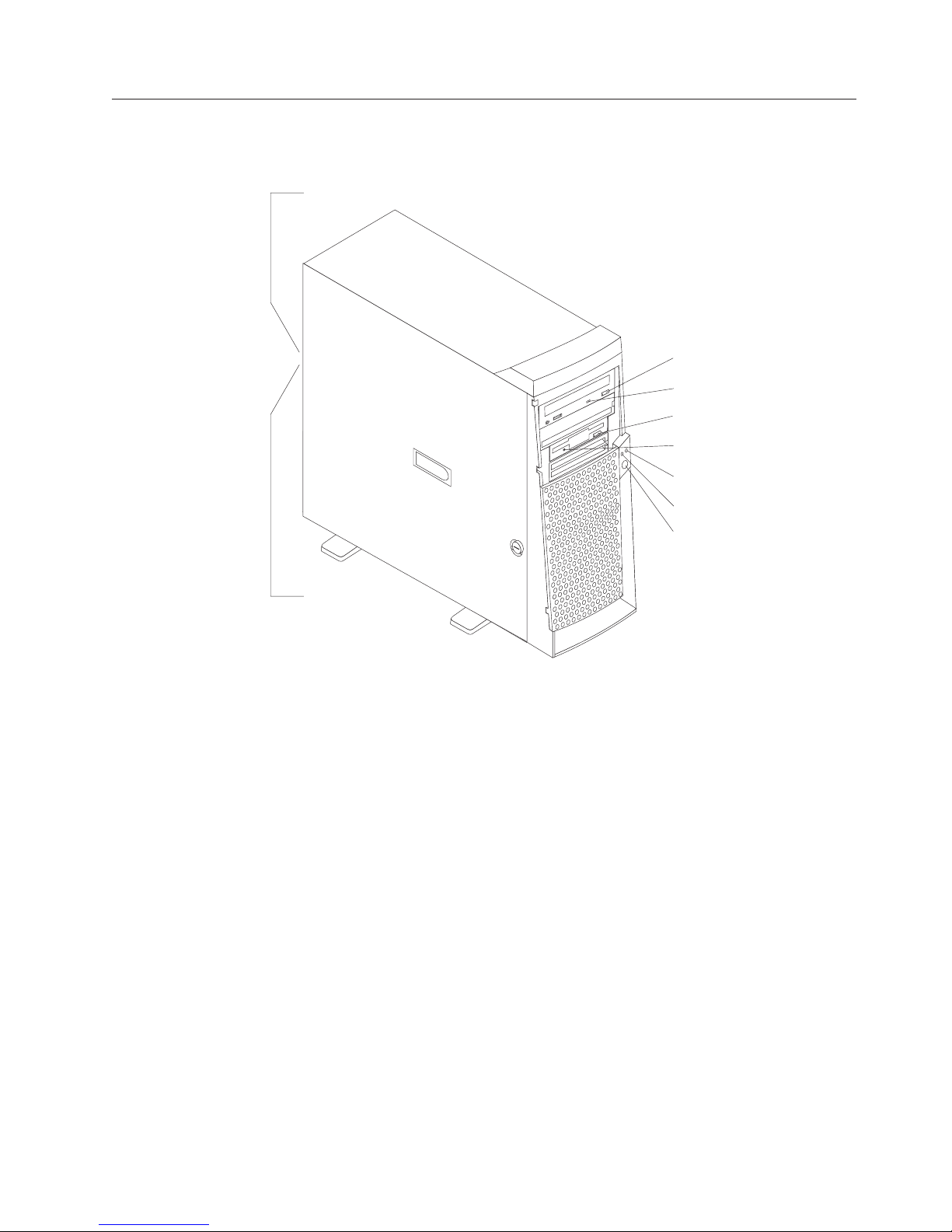
Server controls and indicators
This section identifies the controls and indicators on the front and rear of the
server.
Ethernet speed 100 Mbps
CD-eject
button
CD-ROM drive
activity light
Diskette-eject
button
Diskette drive
activity light
Hard disk drive
activity light
Power-on
light
Power-control
button
Ethernet transmit/
receive activity
CD-eject button: Push this button to open the CD tray to insert or remove a CD.
CD-ROM drive activity light: When this light is on, the CD-ROM drive is in use.
Diskette-eject button: Push this button to release a diskette from the drive.
Diskette drive activity light: When this light is on, the diskette drive is in use.
Ethernet speed 100 MBps: When this light is on, the Ethernet speed is 100 MBps.
When the light is off, the Ethernet speed is 10 MBps. The Ethernet speed light is
located on the Ethernet (RJ-45) connector on the rear of the server.
Ethernet transmit/receive activity: When this light is on, there is activity between
the server and the network. The Ethernet transmit/receive activity light is located
on the Ethernet (RJ-45) connector on the rear of the server.
Hard disk drive activity light: When this light is on, the hard disk drive is in use.
Power-on light: This status indicator lights when you turn on the server.
Power-control button: Press this button to manually turn the server on or off.
See “I/O connector locations” on page 64 for the location of the input/output
(I/O) connectors on the rear of the server.
General information 7
Page 16
Turning on the server
After you plug one end of the server power cord into the power supply outlet on
the rear of the server, and the other end of the power cord into an electrical outlet,
the server can start as follows:
v You can press the power-control-button on the front of the server to start the
server.
v If the server is turned on and a power failure occurs, the server will start
automatically when power is restored.
Turning off the server
You can turn off the server in the following ways:
Statement 5:
CAUTION:
The power control button on the device and the power switch on the power
supply do not turn off the electrical current supplied to the device. The device
also might have more than one power cord. To remove all electrical current from
the device, ensure that all power cords are disconnected from the power source.
2
1
v You can press the power-control button on the front of the server. This starts an
orderly shutdown of the operating system, if this feature is supported by your
operating system, and places the server in standby mode.
Note: After turning off the server, wait at least 5 seconds before you press the
power-control button to turn on the server again.
v You can press and hold the power-control button for more than 4 seconds to
cause an immediate shutdown of the server and place the server in standby
mode. You can use this feature if the operating system stops functioning.
v You can disconnect the server power cords from the electrical outlets to shut off
all power to the server.
Note: After disconnecting the power cords, wait approximately 15 seconds for
your system to stop running.
8 xSeries 200 Type 8479 and xSeries 200VL Type 8481: Hardware Maintenance Manual
Page 17

Diagnostics
This section provides basic troubleshooting information to help you resolve some
common problems that might occur with the server.
If you cannot locate and correct the problem using the information in this section,
refer to “Symptom-to-FRU index” on page 89 for more information.
Diagnostic tools overview
The following tools are available to help you identify and resolve hardware-related
problems:
v POST beep codes
The power-on self-test (POST) generates beep codes and messages to indicate
successful test completion or the detection of a problem. See “POST” for more
information.
v Diagnostic programs and error messages
The server diagnostic programs are provided on the IBM Enhanced Diagnostics
CD. These programs test the major components of the server. See “Diagnostic
programs and error messages” on page 10 for more information.
POST
When you turn on the server, it performs a series of tests to check the operation of
server components and some of the options installed in the server. This series of
tests is called the power-on self-test or POST.
If POST finishes without detecting any problems, the first window of the operating
system or application program appears.
Note:
1. If you have a power-on password or administrator password set, you
must type the password and press Enter, when prompted, before POST
will continue.
2. A single problem might cause several error messages. When this occurs,
work to correct the cause of the first error message. After you correct the
cause of the first error message, the other error messages usually will not
occur the next time you run the test.
POST beep code descriptions
POST generates beep codes to indicate successful completion or the detection of a
problem.
v One short beep indicates the successful completion of POST.
v More than one beep indicates that POST detected a problem. For more
information, see “Beep symptoms” on page 89“.
POST error messages
The possible types of beep codes that your system might emit are:
© Copyright IBM Corp. 2001 9
Page 18

Repeating long beeps
Indicates that a memory error has occurred. Ensure that all DIMMs are
correctly installed.
One long beep and two short beeps
Indicates that a video error has occurred and the BIOS cannot initialize the
video screen to display any additional information. Ensure that the video
adapter is correctly installed.
a list of POST errors, see “POST error messages” on page 95.
For
Small computer system interface messages (some models)
The following table lists actions to take if you receive a SCSI error message.
Note: If the server does not have a SCSI hard disk drive, ignore any message that
indicates that the BIOS is not installed.
You will get these messages only when running the SCSI Select Utility.
Table 2. SCSI messages
SCSI Messages Description
All One or more of the following might be causing the problem.
v A failing SCSI device (adapter or drive)
v An improper SCSI configuration
v Duplicate SCSI IDs in the same SCSI chain
v An improperly installed SCSI terminator
v A defective SCSI terminator
v An improperly installed cable
v A defective cable
Action:
Verify that:
v The external SCSI devices are turned on. External SCSI devices must
be turned on before the server.
v The cables for all external SCSI devices are connected correctly.
v The last device in each SCSI chain is terminated properly.
v The SCSI devices are configured correctly.
If
the above items are correct, run the diagnostic programs to obtain
additional information about the failing device.
Diagnostic programs and error messages
The server diagnostic programs are stored on the IBM Enhanced Diagnostics CD.
These programs provide the primary methods of testing the major components of
the server.
Diagnostic error messages indicate that a problem exists; they are not intended to
be used to identify a failing part. Troubleshooting and servicing of complex
problems that are indicated by error messages should be performed by trained
service personnel.
10 xSeries 200 Type 8479 and xSeries 200VL Type 8481: Hardware Maintenance Manual
Page 19

Sometimes the first error to occur causes additional errors. In this case, the server
displays more than one error message. Always follow the suggested action
instructions for the first error message that appears.
The following sections contain the error codes that might appear in the detailed
test log and summary log when running the diagnostic programs.
The error code format is as follows:
fff-ttt-iii-date-cc-text message
where:
fff is the three-digit function code that indicates the function being
tested when the error occurred. For example, function code 089 is
for the microprocessor.
ttt is the three-digit failure code that indicates the exact test failure
that was encountered.
iii is the three-digit device ID.
date is the date that the diagnostic test was run and the error recorded.
cc is the check digit that is used to verify the validity of the
information.
text message is the diagnostic message that indicates the reason for the problem.
Text messages
The diagnostic text message format is as follows:
Function Name: Result (test specific string)
where:
Function Name
is the name of the function being tested when the error occurred. This
corresponds to the function code (fff) given in the previous list.
Result can be one of the following:
Passed
Failed This result occurs when the diagnostic test discovers an error.
User Aborted
Not Applicable
This result occurs when the diagnostic test completes without any
errors.
This result occurs when you stop the diagnostic test before it is
complete.
This result occurs when you specify a diagnostic test for a device
that is not present.
Aborted
This result occurs when the test could not proceed because of the
server configuration.
Warning
This result occurs when a possible problem is reported during the
diagnostic test, such as when a device that is to be tested is not
installed.
Diagnostics 11
Page 20

Test Specific String
This is additional information that is used to analyze the problem.
Starting the diagnostic programs
The IBM Enhanced Diagnostics programs will isolate the server hardware from
software that you have installed on your hard disk drive. The programs run
independently of the operating system, and must be run either from the CD or from
the diskette. This method of testing is generally used when other methods are not
accessible or have not been successful in isolating a problem suspected to be
hardware related.
An IBM Enhanced Diagnostics CD comes with the server. You can also download
the latest image of the diagnostics from the World Wide Web at
http://www.ibm.com/pc/support.
Using the diagnostics CD
To start the IBM Enhanced Diagnostics from the diagnostics CD, do the following:
1. Turn off the server and any peripheral devices.
2. Turn on all attached devices; then, turn the server on.
3. When you see Press F1 For Configuration/Setup, press the F1 key.
4. When the Configuration/Setup Utility menu appears, select Start Options.
5. From the Start Options menu, select Startup Sequence.
6. Note the device selected as the First Startup Device. Later, you must restore
this setting.
7. Select CD-ROM as the First Startup Device.
8. Press Esc two times to return to the Configuration/Setup Utility menu.
9. Place the IBM Enhanced Diagnostics CD in the CD-ROM drive.
10. Select Save & Exit Setup and follow the prompts. The diagnostics will load.
Follow the instructions on the screen to run the diagnostics.
Important
When you finish running the diagnostics and utilities, remove the CD from the CD-ROM
drive and turn off the server. You must restore the First Startup Device to the original
setting. Use steps 2 through 8 of this procedure to do this.
Creating a diagnostics diskette from the CD: To create a diagnostics floppy
diskette from the CD, do the following:
1. Format a floppy diskette (or have a preformatted diskette available).
2. Boot the system from the diagnostics CD.
3. From the menu that appears, select Create diagnostic diskette.
4. Insert the formatted floppy diskette into the floppy disk drive when the
message on the screen prompts you to do so, and press Enter.
5. The diagnostics CD can then be removed and the system rebooted with the
newly created diskette.
Downloading the diagnostics program
Do the following to download the latest image of the IBM Enhanced Diagnostics
from the World Wide Web and create a startable Enhanced Diagnostics diskette:
1. Go to the following World Wide Web site: http://www.ibm.com/pc/support
12 xSeries 200 Type 8479 and xSeries 200VL Type 8481: Hardware Maintenance Manual
Page 21

2. Download the diagnostics file for the server to a hard disk drive directory (not
to a diskette).
3. Go to a DOS prompt and change to the directory where the file was
downloaded.
4. Insert a blank high-density diskette in diskette drive A.
5. Type in the following, and then press Enter: filename a: where filename is the
name of the file you downloaded from the Web.
The downloaded file is self-extracting and will be copied to the diskette. When the
copy completes, you have a startable IBM Enhanced Diagnostics diskette.
Using the diagnostic diskette
Do the following to start the IBM Enhanced Diagnostics using the diagnostics
diskette, do the following:
1. Turn off the server and any peripheral devices.
2. Insert the IBM Enhanced Diagnostics diskette into the diskette drive.
3. Turn on all attached devices; then, turn on the server.
4. Follow the instructions on the screen.
5. Place the IBM Enhanced Diagnostics CD in the CD-ROM drive. The diagnostics
will load. Follow the instructions on the screen to run the diagnostics.
the tests have completed, you can view the Test Log by selecting Utility
When
from the top of the screen.
If the hardware checks out OK but the problem persists during normal server
operations, a software error might be the cause. If you suspect a software problem,
refer to the information that comes with the software package.
Viewing the test log
The test log records data about system failures and other pertinent information.
The test log will not contain any information until after the diagnostic program has
run.
Note: If you already are running the diagnostic programs, begin with step 4
1. Insert the IBM Enhanced Diagnostics CD or diskette in the appropriate drive.
2. Turn on the system and watch the screen.
If the system is on, shut down your operating system and restart the system.
3. If a power-on password is set, the system prompts you for it. Type in the
appropriate password; then, press Enter.
4. Run the appropriate diagnostics program and when the Diagnostic Programs
screen appears, select Utility.
5. Select View Test Log from the list that appears; then, follow the instructions on
the screen.
6. You can save the test log to a file on a diskette or to your hard disk drive.
Note: The system maintains the test-log data while the system is powered on.
Diagnostic error message tables
For descriptions of the error messages that might appear when you run the
diagnostic programs, see “Diagnostic error codes” on page 90. If diagnostic error
When you turn off the power to the server, the test log is cleared.
Diagnostics 13
Page 22

Power checkout
messages appear that are not listed in those tables, make sure that the server has
the latest levels of BIOS, Advanced System Management Processor, ServeRAID,
and diagnostics microcode installed.
Power problems can be difficult to troubleshoot. For instance, a short circuit can
exist anywhere on any of the power distribution busses. Usually a short circuit will
cause the power subsystem to shut down because of an overcurrent condition.
A general procedure for troubleshooting power problems is as follows:
1. Power off the server and disconnect the AC cord(s).
2. Check for loose cables in the power subsystem. Also check for short circuits, for
instance if there is a loose screw causing a short circuit on a circuit board.
3. Remove adapters and disconnect the cables and power connectors to all
internal and external devices until server is at minimum configuration required
for power on (see ″Minimum operating requirements″ on page 97).
4. Reconnect the AC cord and power on the server. If the server powers up
successfully, replace adapters and devices one at a time until the problem is
isolated. If server does not power up from minimal configuration, replace FRUs
of minimal configuration one at a time until the problem is isolated.
To use this method it is important to know the minimum configuration required
for a server to power up (see page 97).
Recovering BIOS
If the BIOS code has become damaged, such as from a power failure during a flash
update, you can recover the BIOS code using a BIOS flash diskette.
You can obtain a BIOS flash diskette from one of the following sources:
v Use the ServerGuide program to make a BIOS flash diskette.
v Download files from the World Wide Web to make a BIOS flash diskette. Go to
Complete
1. When prompted, insert the BIOS flash diskette into the diskette drive.
2. Restart the server. The BIOS begins the power-on self-test.
3. The BIOS flash utility automatically starts.
4. When prompted as to whether you want to save the current code to a diskette,
5. When prompted, press Y to continue the flash process.
6. The system automatically starts the flash utility a second time.
7. When prompted as to whether you want to save the current BIOS code, stop
8. Restart the server, which should start up normally.
http://www.ibm.com/pc/support/ select IBM System Support, and then make
the selections for your system.
the following steps to recover the BIOS code:
select N.
the process by removing the BIOS flash diskette from the diskette drive.
14 xSeries 200 Type 8479 and xSeries 200VL Type 8481: Hardware Maintenance Manual
Page 23
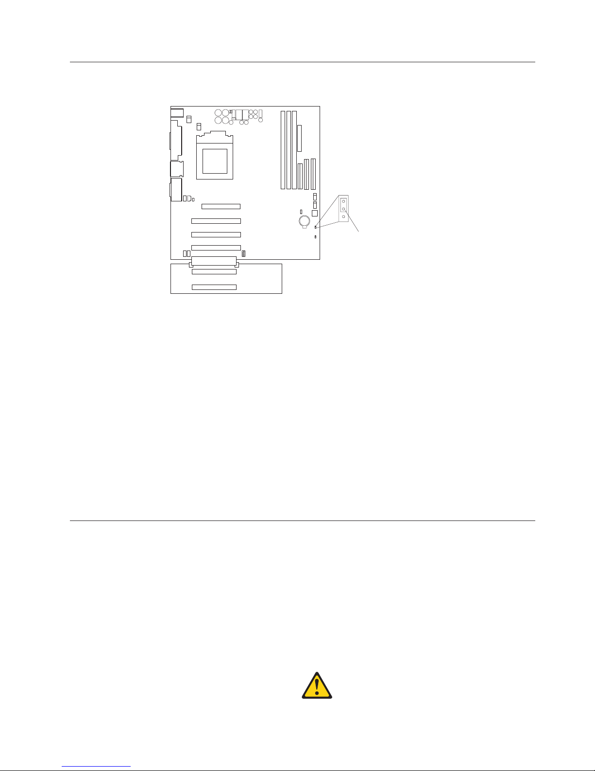
Clearing CMOS
If you need to erase configuration information, you must move the CMOS jumper.
1
2
3
CMOS jumper
(JBAT1)
The default position is a jumper installed on pins 1 and 2. Before you change the
position of this jumper, you must turn off the server and peripheral devices, and
disconnect all external cables and power cords. Remove the cover and then move
the jumper to pins 2 and 3.
After moving the jumper, wait at least 5 minutes for the CMOS information to
clear.
Changing the position of this jumper erases all configuration and setup
information, including the power-on and administrator passwords. Therefore, you
must reconfigure the server after clearing CMOS memory (see “Configuration” on
page 25). If possible, record the server configuration information before moving the
CMOS jumper.
After you clear the CMOS information, move the jumper back to its normal
position (pins 1 and 2). Reconnect the external cables and power cords; then, turn
on the peripheral devices and the server.
Replacing the battery
When replacing the battery, you must replace it with a lithium battery of the same
type from the same manufacturer. To avoid possible danger, read and follow the
safety statement below.
To order replacement batteries, call 1-800-772-2227 within the United States, and
1-800-465-7999 or 1-800-465-6666 within Canada. Outside the U.S. and Canada, call
your IBM reseller or IBM marketing representative.
Note: After you replace the battery, you must reconfigure your system and reset
the system date and time.
Diagnostics 15
Page 24
CAUTION:
When replacing the battery, use only IBM Part Number 33F8354 or an equivalent
type battery recommended by the manufacturer. If the server has a module
containing a lithium battery, replace it only with the same module type made by
the same manufacturer. The battery contains lithium and can explode if not
properly used, handled, or disposed of.
Do not:
v Throw or immerse into water
v Heat to more than 100°C (212°F)
v Repair or disassemble
Dispose
of the battery as required by local ordinances or regulations.
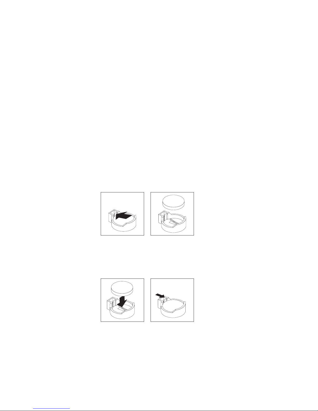
Do the following to replace the battery:
1. Read “Before you begin” on page 40, and follow any special handling and
installation instructions supplied with the replacement battery.
2. Turn off the server and peripheral devices and disconnect all external cables
and power cords; then, remove the server cover.
3. Remove the battery:
a. Use one finger to press the top of the battery clip away from the battery
until the battery releases upward from the socket.
b. Lift and remove the battery from the battery socket.
4. Do the following to insert the new battery:
a. Tilt the battery so that you can insert it into the socket under the battery
clip.
b. As you slide it under the battery clip, press the battery down into the
socket.
5. Reinstall the server cover and connect the cables.
6. Turn on the server.
7. Start the Configuration/Setup Utility program and set configuration
parameters.
v Set the server date and time.
v Set the power-on password.
v Reconfigure the server.
16 xSeries 200 Type 8479 and xSeries 200VL Type 8481: Hardware Maintenance Manual
Page 25

Temperature checkout
Proper cooling of the server is important for proper operation and server reliability.
For a typical xSeries server, you should make sure:
v Each of the drive bays has either a drive or a filler panel installed
v Each of the power supply bays has either a power supply or a filler panel
installed
v The server cover is in place during normal operation
v There is at least 50 mm (2 inches) of ventilated space at the sides of the server
and 100 mm (4 inches) at the rear of the server
v The server cover is removed for no longer than 30 minutes while the server is
operating
v The processor housing cover covering the processor and memory area is
removed for no longer that ten minutes while the server is operating
v A removed hot-swap drive is replaced within two minutes of removal
v Cables for optional adapters are routed according to the instructions provided
with the adapters (ensure that cables are not restricting air flow)
v The fans are operating correctly and the air flow is good
v A failed fan is replaced within 48 hours
In addition, ensure that the environmental specifications for the server are met. See
“Features and specifications” on page 3.
Note: The speed of the fans will increase if:
v One fan fails.
v Ambient temperature gets too high.
Diagnosing errors
To find solutions to problems that have definite symptoms, see “Error symptoms”
on page 92.
If you cannot find the problem there, go to “Starting the diagnostic programs” on
page 12 to test the server.
If you have just added new software or a new option and the server is not
working, do the following before using the error symptoms table:
v Remove the software or device that you just added.
v Run the diagnostic tests to determine if the server is running correctly.
v Reinstall the new software or new device.
Troubleshooting the Ethernet controller
This section provides troubleshooting information for problems that might occur
with the 10/100 MBps Ethernet controller.
Network connection problems
If the Ethernet controller cannot connect to the network, check the following:
v Make sure that the cable is installed correctly.
The network cable must be securely attached at all connections. If the cable is
attached but the problem persists, try a different cable.
Diagnostics 17
Page 26

If you set the Ethernet controller to operate at 100 MBps, you must use Category
5 cabling.
If you directly connect two workstations (without a hub), or if you are not using
a hub with X ports, use a crossover cable.
Note: To determine whether a hub has an X port, check the port label. If the
label contains an X, the hub has an X port.
v Determine if the hub supports auto-negotiation. If not, try configuring the
integrated Ethernet controller manually to match the speed and duplex mode of
the hub.
v Check the LAN activity light (if available) on the front of the server. The LAN
activity light illuminates when the Ethernet controller sends or receives data
over the Ethernet network. If the LAN activity light is off, make sure that the
hub and network are operating and that the correct device drivers are loaded.
v Make sure that you are using the correct device drivers, supplied with the
server.
v Check for operating server-specific causes for the problem.
v Make sure that the device drivers on the client and server are using the same
protocol.
v Test the Ethernet controller.
The way you test the Ethernet controller depends on which operating system
you are using (see the Ethernet controller device driver README file).
Ethernet controller troubleshooting chart
You can use the following troubleshooting chart to find solutions to 10/100 MBps
Ethernet controller problems that have definable symptoms.
Table 3. Ethernet troubleshooting chart
Ethernet controller
problem
The server stops
running when loading
device drivers.
The LAN activity light
(when available) does
not light.
Suggested Action
The PCI BIOS interrupt settings are incorrect.
Check the following:
v Determine if the IRQ setting assigned to the Ethernet controller
is also assigned to another device in the Configuration/Setup
Utility program.
Although interrupt sharing is allowed for PCI devices, some
devices do not function well when they share an interrupt with
a dissimilar PCI device. Try changing the IRQ assigned to the
Ethernet controller or the other device. For example, for
NetWare Versions 3 and 4 it is recommended that disk
controllers not share interrupts with LAN controllers.
v Make sure that you are using the most recent device driver
available from the World Wide Web.
v Run the network diagnostic program.
Check the following:
v Make sure that you have loaded the network device drivers.
v The network might be idle. Try sending data from this
workstation.
v Run diagnostics on the LEDs.
18 xSeries 200 Type 8479 and xSeries 200VL Type 8481: Hardware Maintenance Manual
Page 27

Table 3. Ethernet troubleshooting chart (continued)
Ethernet controller
Suggested Action
problem
Data is incorrect or
sporadic.
Check the following:
v Make sure that you are using Category 5 cabling when
operating the server at 100 MBps.
v Make sure that the cables do not run close to noise-inducing
sources like fluorescent lights.
The Ethernet controller
stopped working when
another adapter was
added to the server.
Check the following:
v Make sure that the cable is connected to the Ethernet controller.
v Make sure that your PCI server BIOS is current.
v Reseat the adapter.
v Determine if the IRQ setting assigned to the Ethernet adapter is
also assigned to another device in the Configuration/Setup
Utility program.
Although interrupt sharing is allowed for PCI devices, some
devices do not function well when they share an interrupt with
a dissimilar PCI device. Try changing the IRQ assigned to the
Ethernet adapter or the other device.
The Ethernet controller
stopped working
without apparent
cause.
Check the following:
v Run diagnostics for the Ethernet controller.
v Try a different connector on the hub.
v Reinstall the device drivers. Refer to your operating system
documentation and to the ServerGuide information.
Ethernet controller messages
The integrated Ethernet controller might display messages from the following
device drivers:
v Novell NetWare™ or IntraNetWare system open data-link interface (ODI)
v Network driver interface specification (NDIS) adapter for level 4.0 (Windows
NT)
Novell NetWare or IntraNetWare system ODI driver teaming
messages
This section provides explanations of the error messages for the Novell NetWare or
IntraNetWare system ODI driver, and suggested actions to resolve each problem.
Table 4. NetWare driver messages for the Ethernet controller
Message Description
Couldn’t allocate resources. Explanation: An unknown error has occurred when trying
AFT group for primary
adapter in slot nnn already
exists.
to allocate needed resources for the AFT Module.
Action:
v Check the server configuration. If the problem persists,
contact your network supplier.
v Verify that the Ethernet controller is enabled. If the
Ethernet controller is enabled, run the diagnostic
programs.
Explanation: An attempt was made to rebind an adapter
already in an AFT group.
Action: Check the AFT slot numbers for existing AFT
teams. If the problem persists, contact your network
supplier.
Diagnostics 19
Page 28

Table 4. NetWare driver messages for the Ethernet controller (continued)
Message Description
Error locating device control
table (DCT) addresses in
internal table. Make sure that
you have loaded LAN
drivers after loading
AFT.NLM.
Explanation: The bind command was entered prior to
loading the device driver. The device driver must be loaded
after loading AFT.NLM, but before any bind command can
be issued.
Action: Load the driver for the supported adapter and try
loading the AFT module again. If the problem persists,
contact your network supplier.
Insufficient number of
arguments specified.
Explanation: The appropriate or expected number of
parameters was not entered in a command.
Action: Check the parameters required for the given
command. If the problem persists, contact your network
supplier.
Duplicate slot numbers
detected.
Explanation: An attempt has been made to bind the same
slot number more than once.
Action: Check the slot numbers entered during the bind.
Adapter slot numbers must be valid and unique. If the
problem persists, contact your network supplier.
’xxx’ is not supported for
AFT team.
Explanation: A bind command has been issued for adapters
not supported by AFT.NLM.
Action: Make sure that you attempt to bind only adapters
supported by AFT.NLM.
Primary and Secondary
adapters do not match. AFT
group is not created.
Explanation: A bind command was entered for an adapter
team that is a combination of server and client adapters. An
AFT team must be a grouping of the same classification of
adapter.
Action: Verify that all the adapters bound in a team are of
the same classification.
Requested number of
Secondary cards are not
found.
Explanation: The number of adapters specified in the bind
command could not be located.
Action: Verify the numbers and slot locations of the
adapters to be bound. If the problem persists, contact your
network supplier.
Failed to create AFT group.
Make sure that the drivers
for supported adapters are
loaded, primary adapter is
bound to protocols, and
Explanation: Binding of protocol failed. Protocol is either
not bound to any adapter or is bound to more than one
adapter in the group.
Action: Ensure that the protocol is bound to only adapter in
an AFT team.
secondary adapter is not
bound to any protocols.
Error identifying slot
numbers for the specified
board names.
Explanation: The mapping between the board name entered
and the slot number for an adapter could not be
established.
Action: Check the board name for the adapter before
issuing the bind command. If the problem persists, contact
your network supplier.
Can’t unbind specified slot
from AFT group. Make sure
that the slot you specified is
for the primary adapter in an
Explanation: The number entered in the unbind command
was not the primary adapter in an AFT group.
Action: Reissue the unbind command and specify the slot
number for the primary adapter.
AFT group.
20 xSeries 200 Type 8479 and xSeries 200VL Type 8481: Hardware Maintenance Manual
Page 29

Table 4. NetWare driver messages for the Ethernet controller (continued)
Message Description
LAN adapter at slot nnnn
(Port 0xaa) failed to reset.
Check the state of the
adapter.
Explanation: The adapter that you specified could not be
initialized.
Action:
1. Load the driver for the supported adapter.
2. Check that the adapter is seated properly in the slot and
try loading the AFT module again.
the problem persists, contact your network supplier.
If
AFT is not supported on this
version of NetWare™.
Explanation: The NetWare on the server is not a version
supported by AFT.
Action: Load and bind AFT only on supported versions of
NetWare (currently version 4.11 and above).
Failed to allocate resources
tags.
Explanation: An unknown error has occurred when trying
to allocate needed resources for the AFT module.
Action: Check server configuration. If the problem persists,
contact your network supplier.
Please unload all LAN
drivers before unloading
AFT.NLM.
Explanation: An attempt was made to unload the AFT.NLM
module before unloading the adapter driver.
Action: Unload the adapter driver before unloading the
AFT module.
NDIS 4.0 Windows driver messages
This section contains the error messages for the NDIS 4.0 drivers. The explanation
and recommended action are included with each message.
Table 5. NDIS (Windows NT or Windows 2000) driver messages for the Ethernet controller
Error code
(hex) Description
0x00 Explanation: The driver could not register the specified interrupt.
Action: Using the Configuration/Setup Utility program, make sure that a
PCI interrupt is assigned to your Ethernet card, and that Ethernet is
enabled.
0x01 Explanation: One of the PCI cards did not get the required resources.
Action: Using the Configuration/Setup Utility program, make sure that a
PCI interrupt is assigned to your Ethernet card, and that Ethernet is
enabled.
0x02 Explanation: Bad node address (multicast address).
Action: Make sure the locally administered address is valid, if one is
specified. The address can not be a multicast address.
0x03 Explanation: Failed self-test.
Action: Make sure a cable is attached to the Ethernet connector.
0x0D Explanation: Could not allocate enough memory for transmit queues.
Action:
1. From the Windows NT desktop, select Start ” Control Panel ”
Networks ” Adapters.
2. Select your IBM Ethernet adapter from the list.
3. Select Properties ” Advanced.
4. Lower the resource values that apply to the transmit queue.
Diagnostics 21
Page 30

Table 5. NDIS (Windows NT or Windows 2000) driver messages for the Ethernet
controller (continued)
Error code
(hex) Description
0x0E Explanation: Could not allocate enough memory for receive queue.
Action:
1. From the Windows NT desktop, select Start ”Control Panel ”Networks
”Adapters.
2. Select your IBM Ethernet adapter from the list.
3. Select Properties ”Advanced.
4. Lower the resource values that apply to the receive queue.
0x0F Explanation: Could not allocate enough memory for other structures.
Action:
1. From the Windows NT desktop, select Start ” Control Panel ”
Networks ” Adapters.
2. Select your IBM Ethernet adapter from the list.
3. Select Properties ”Advanced.
4. Lower the value for the resource named in the message.
0x10 Explanation: Did not find any Ethernet controllers.
Action: Using the Configuration/Setup Utility program, make sure that
Ethernet is enabled.
0x11 Explanation: Multiple Ethernet controllers found, but none matched the
required ID.
Action: Using the Configuration/Setup Utility program, make sure that
Ethernet is enabled.
0x13 Explanation: Did not find any Ethernet controllers that matched the
required subven/subdev.
Action: Using the Configuration/Setup Utility program, make sure that
Ethernet is enabled.
0x16 Explanation: Single adapter found, but multiple instances tried to load.
Action: Using the Configuration/Setup Utility program, make sure that
Ethernet is enabled, and that the slot containing the IBM xSeries 200
10/100 Ethernet Adapter or the IBM 10/100 Etherjet PCI adapter is
enabled.
0x17 Explanation: Slot parameter not specified in the registry.
Action: Remove the adapter driver and reinstall it.
Ethernet teaming messages:
This section displays the messages associated with Ethernet teaming.
22 xSeries 200 Type 8479 and xSeries 200VL Type 8481: Hardware Maintenance Manual
Table 6. NDIS (Windows NT or Windows 2000) driver teaming messages for the Ethernet
controller
Event ID Type Description
01 Error Explanation: Team name and physical adapter name are
02 Error Explanation: Unable to allocate required resources.
the same. This is an invalid configuration.
Action: Reconfigure the adapter team by double-clicking
the PROSet icon in the control panel.
Action: Free some memory resources and restart.
Page 31

Table 6. NDIS (Windows NT or Windows 2000) driver teaming messages for the Ethernet
controller (continued)
Event ID Type Description
03 Error Explanation: Unable to read required registry
parameters.
Action: Reconfigure the adapter team by double-clicking
the PROSet icon in the control panel.
04 Error Explanation: Unable to bind to physical adapter.
Action: Reconfigure the adapter team by double-clicking
the PROSet icon in the control panel.
05 Error Explanation: Unable to initialize an adapter team.
Action: Reconfigure the adapter team by double-clicking
the PROSet icon in the control panel.
06 Informational Explanation: Team nn. Primary adapter is initialized.
Action: None.
07 Informational Explanation: Team nn. Secondary adapter is initialized.
Action: None.
08 Informational Explanation: Team nn. Virtual adapter or Team is
initialized.
Action: None.
09 Informational Explanation: Team nn. Primary adapter is switching
over.
Action: None.
10 Warning Explanation: Team nn. Adapter link down.
Action: Make sure the adapter is functioning properly.
11 Informational Explanation: Team nn. Secondary adapter took over.
Action: None.
12 Warning Explanation: Team nn. Secondary adapter is deactivated
from the Team.
Action: Make sure the secondary adapter is functioning
properly and that the adapter cable is securely
connected to the LAN.
13 Informational Explanation: Team nn. Secondary adapter has rejoined
the Team.
Action: None.
14 Informational Explanation: Team nn. Secondary adapter link is up.
Action: None.
15 Error Explanation: Team nn. The last adapter has lost its link.
Network connection has been lost.
Action: Shut down the server and replace the adapters;
then, restart the server to reestablish the connection.
16 Informational Explanation: Team nn. An adapter has reestablished the
link. Network connection has been restored.
Action: None.
17 Informational Explanation: Team nn. Preferred primary adapter has
been detected.
Action: None.
18 Informational Explanation: Team nn. Preferred secondary adapter has
been detected.
Action: None.
Diagnostics 23
Page 32

Table 6. NDIS (Windows NT or Windows 2000) driver teaming messages for the Ethernet
controller (continued)
Event ID Type Description
19 Informational Explanation: Team nn. Preferred primary adapter took
over.
Action: None.
20 Informational Explanation: Team nn. Preferred secondary adapter took
over.
Action: None.
21 Warning Explanation: Team nn. Primary adapter does not sense
any Probes. Possible reason: partitioned Team.
Action: Make sure the cables of the adapter team are
connected to the same LAN segment. Reconfigure the
team if necessary.
24 xSeries 200 Type 8479 and xSeries 200VL Type 8481: Hardware Maintenance Manual
Page 33

Configuration
The following configuration programs are provided with the server:
v Configuration/Setup Utility
The Configuration/Setup Utility program is part of the BIOS code that comes
with the server. You can use this program to configure serial- and
parallel-connector assignments, change the drive startup sequence, set the date
and time, and set passwords. See “Using the Configuration/Setup Utility
program” for more information.
v SCSISelect Utility (some models)
With the SCSISelect Utility program, you can configure the devices that are
attached to the SCSI adapter. Use this program to change default values, resolve
configuration conflicts, and perform a low-level format on a SCSI hard disk
drive. See “Using the SCSISelect utility program (some models)” on page 28 for
more information.
v PXE Boot Agent Utility
The Preboot eXecution Environment (PXE) Boot Agent Utility program is part of
the BIOS code that comes with the server. Depending on the server model, you
can use this program to change network startup (boot) protocols and startup
order, to select operating-system wake-up support, and to set menu wait times.
See “Using the PXE Boot Agent Utility program” on page 31 for more
information.
Attention: The network startup protocols and startup order options are not
supported on this product.
v ServeRAID programs
The ServeRAID programs come with the optional ServeRAID adapters and with
server models that have a ServeRAID adapter preinstalled. If a ServeRAID
adapter has been installed in the server, you must use the ServeRAID
configuration program to define and configure the disk-array subsystem before
you install the operating system. More information is available from the IBM
xSeries Documentation CD that was shipped with the server.
v ServerGuide CDs
The ServerGuide CDs include software setup and installation tools specifically
designed for IBM xSeries servers. You can use these CDs during the initial
installation of the server to configure the server hardware and simplify the NOS
installation. The ServerGuide CDs also contain a collection of application
programs, which you can install after the server is up and running. See “Using
the ServerGuide CDs” on page 32 for more information.
Using the Configuration/Setup Utility program
This section provides the instructions for starting the Configuration/Setup Utility
program and also provides descriptions of the menu choices that are available.
Starting the Configuration/Setup Utility program
Complete the following steps to start the Configuration/Setup Utility program:
1. Turn on the server and watch the monitor screen.
2. When the message Press F1 for Configuration/Setup appears, press the F1
key.
© Copyright IBM Corp. 2001 25
Page 34

3. Follow the instructions that appear on the screen.
Choices available from the Configuration/Setup main menu
From the Configuration/Setup Utility main menu, you can select settings that you
want to change. The Configuration/Setup Utility main menu is similar to the
following illustration:
CMOS Setup Utility - Copyright (c) 1984 - 2001 Award Software
Configuration/Setup Utility
Select Option:
System Summary
Product Data
Devices & I/O Ports
Start Options
Frequency Control
Date and Time
System Security
Advanced Setup
Power Management Setup
Save & Exit Setup
Load Optimized Defaults
Exit Without Saving
Move Enter: Select F1: General Help
F10: Save ESC: Exit
Notes:
1. You can press the F1 key to display help information for a selected menu item.
2. Some menu choices might differ, depending on the types of passwords set for
the system and IBM system management adapters, or in the version of BIOS
code installed on the server.
Descriptions of the choices that are available from the main menu are as follows:
v System summary
Select this choice to display configuration information. This includes the type
and speed of the microprocessors and the amount of memory that is installed.
Changes that you make to configuration settings appear on this summary
screen. Yo u cannot edit the fields.
This choice appears on both the full and limited Configuration/Setup Utility
menus.
v Product data
Select this choice to view system information, such as the machine type and
model, the server serial number, and the revision level or issue date of the BIOS
stored in the flash electronically erasable programmable read-only memory
(EEPROM).
v Devices and I/O ports
Select this choice to view or change the assignments for devices and
input/output ports. This choice appears only on the full Configuration/Setup
Utility main menu.
v Start Options
Select this choice to view or change the start options. Start options take effect
when you start the server.
26 xSeries 200 Type 8479 and xSeries 200VL Type 8481: Hardware Maintenance Manual
Page 35

You can select keyboard operating characteristics, such as the keyboard speed.
You also can specify whether the server starts with the keyboard number lock on
or off.
The server uses a startup sequence to determine the device from which the
operating system starts. For example, you can define a startup sequence that
checks for a startable diskette in the diskette drive, then checks the hard disk
drive in a drive bay, and then checks a network adapter.
You can enable a virus-warning test that checks for changes in the master boot
record at startup. You also can choose to run POST in the quick mode, and read
the microprocessor serial number.
v Frequency Control
Select this choice to enable or disable the auto-detect DIMM/PCI clock.
v Date and Time
Select this choice to set the system date and time.
The system time is in a 24-hour format: hour:minute:second.
Note: You may also set the date and time using the procedures provided on the
ServerGuide CDs.
v System Security
Select this choice to set a power-on or an administrator password. See “Using
passwords” on page 28 for more information.
v Advanced Setup
Select this choice to change values for advanced hardware features, such as
Cache Control and PCI configuration.
A message appears above the choices on this menu to alert you that the system
might malfunction if these options are configured incorrectly. Follow the
instructions on the screen carefully.
– Cache Control
Select this choice to enable or disable the microprocessor cache.
Attention: The Cache Control should only be modified by an IBM
authorized service representative.
– ROM Shadowing
Select this choice to enable or disable the state of a ROM shadowing.
– Chipset Feature
Select this choice to modify settings that control features of the core chip set
on the system board.
Attention: The Chipset Feature should only be modified by an IBM
authorized service representative.
– Memory Settings
If a memory error is detected during POST or memory configuration, the
server can automatically disable the failing memory bank and continue
operating with reduced memory capacity. If this occurs, you must manually
enable the memory bank after the problem is corrected. Select Memory
Settings from the Advanced Setup menu, use the arrow keys to highlight the
bank that you want to enable; then, use the arrow keys to select Enable.
Power Management Setup
v
Select this choice to enable or disable system power savings.
v Save and Exit Setup
Select this choice to save the customized settings.
Configuration 27
Page 36

v Load Optimized Defaults
Select this choice to discard changes and restore the factory settings.
v Exit Without Saving
Select this choice if you want to exit without saving changes, or if no changes
have been made.
Using passwords
The System Security choice appears only on the full Configuration/Setup Utility
menu. After you select this choice, you can set a power-on password or an
administrator password.
You can use any combination of up to seven characters (A–Z, a–z, and 0–9) for the
power-on password. Keep a record of the password in a secure place. If you forget
the power-on password, you can regain access to the server through either of the
following methods:
v Start the Configuration/Setup Utility program and change the power-on
password.
v Change the jumper position on the CMOS jumper as described in “Clearing
CMOS” on page 15.
v If both a power-on and administrator password are set, you can type either
password at the password prompt that appears as you start the computer. However,
if you want to change any settings in the Configuration/Setup Utility program,
you must type the administrator password at the password prompt that appears
when you try to access the Configuration/Setup Utility program. If you type the
power-on password at this prompt, you will be able to view limited information
in the Configuration/Setup Utility program, but you will not be able to change
any settings.
Using the SCSISelect utility program (some models)
SCSISelect is a built-in, menu-driven configuration utility program that you can
use to:
v View the default SCSI IDs
v Locate and correct configuration conflicts
The following sections provide the instructions for starting the SCSISelect Utility
program and descriptions of the menu choices that are available.
Note: If the server has a redundant arrays of independent disks (RAID) adapter
installed, use the configuration method that is supplied with the RAID
adapter to view or change SCSI settings for attached devices.
Starting the SCSISelect utility program
Complete the following steps to start the SCSISelect Utility program:
1. Turn on the server.
2. When the <<< Press <CTRL><A> for SCSISelect¬ Utility! >>> prompt
appears, press Ctrl+A.
3. When the Would you like to configure the host adapter or run the SCSI
disk utility? question appears, make your selection and press Enter.
4. Use the arrow keys to select a choice from the menu.
v Press Esc to exit the SCSI Select Utility program.
28 xSeries 200 Type 8479 and xSeries 200VL Type 8481: Hardware Maintenance Manual
Page 37

v Press the F5 key to switch between color and monochrome modes (if your
monitor permits).
Follow the instructions on the screen to change the settings of the selected
5.
items; then, press Enter.
Choices available from the SCSISelect menu
The following choices appear on the SCSISelect Utility menu:
v Configure/View Host Adapter Settings
Select this choice to view or change the SCSI controller settings. To reset the
SCSI controller to its default values, press the F6 key; then, follow the on-screen
instructions.
You can view or change the following controller settings:
– Host Adapter SCSI ID
Select this choice to view the SCSI controller identification (ID), which is
usually 7.
– SCSI Parity Checking
Select this choice to view the assigned value. The assigned value is Enabled,
and cannot be changed.
– Host Adapter SCSI Termination
Select this choice to view the assigned value. The assigned value is Automatic,
and cannot be changed.
– Boot Device Options
Select this choice to configure startable-device parameters. Before you can
make updates, you must know the ID of the device whose parameters you
want to configure.
– SCSI Device Configuration
Select this choice to configure SCSI-device parameters. Before you can make
updates, you must know the ID of the device whose parameters you want to
configure.
Note: The Maximum Sync Transfer Rate is the transfer rate for Ultra SCSI
devices.
- The transfer rate for Ultra 160 low voltage differential (LVD) devices
is 160.0 MBps.
- The transfer rate for Ultra2 SCSI LVD devices is 80.0 MBps.
- The transfer rate for Fast SCSI devices is 20.0 MBps.
Advanced Configuration Options
–
Select this choice to view or change the settings for advanced configuration
options. These options include support for large hard disk drives and support
for drives with UltraSCSI speeds.
Configuration 29
Page 38

v SCSI Disk Utilities
Select this choice to view the SCSI IDs that are assigned to each device or to
format a SCSI device.
To use the utility program, select a drive from the list. Read the on-screen
instructions carefully before making a selection.
Note: If you press Ctrl+A before the selected drives are ready, an Unexpected
SCSI Command Failure screen might appear. Restart the server and watch
the SCSISelect messages as each drive starts. After the drive that you
want to view or format starts, press Ctrl+A.
v Format Disk
Attention: The Low-Level Format program erases all data and programs.
Select this choice to perform a low-level format on a hard disk drive. Depending
on the hard disk drive capacity, the Low-Level Format program could take up to
two hours.
Use the Low-Level Format program:
– When you are installing software that requires a low-level format.
– When you get recurring messages from the diagnostic tests directing you to
run the Low-Level Format program on the hard disk drive
– As a last resort before replacing a failing hard disk drive
If the server has a PCI RAID adapter installed, refer to the RAID adapter
Note:
documentation for instructions for performing low-level formats on hard
disk drives attached to the adapter.
To start the Low-Level Format program:
1. If the hard disk drive is working, make a backup copy of all the files and
programs on the hard disk drive. (See the operating system information for
instructions.)
2. Select Format Disk; then, follow the instructions on the screen.
Note: Hard disk drives normally contain more tracks than their stated
capacity (to allow for defective tracks). A message appears on the
screen if the defect limit is reached. If this happens, replace the hard
disk drive.
30 xSeries 200 Type 8479 and xSeries 200VL Type 8481: Hardware Maintenance Manual
Page 39

Using the PXE Boot Agent Utility program
The PXE boot agent is a built-in, menu-driven configuration utility program that
you can use to:
v Select whether to display the setup prompt
v Set menu wait time
v Select operating-system wake-up support
Attention: The network startup protocols and startup order options are not
supported on this product.
following sections provide instructions for starting the PXE Boot Agent Utility
The
program and descriptions of the menu choices that are available.
Starting the PXE Boot Agent Utility program
To start the PXE Boot Agent Utility program:
1. Turn on the server.
2. When the Initializing Intel (R) Boot Agent Version X.X.XX PXE 2.0 Build
XXX (WfM 2.0) prompt appears, press Ctrl+S.
Note: By default, you will have 2 seconds after the prompt appears on the
screen to press Ctrl+S.
3. Use the arrow keys or press Enter to select a choice from the menu.
v Press Esc to return to the previous menu.
v Press the F4 key to exit.
Follow the instructions on the screen to change the settings of the selected
4.
items; then, press Enter.
Choices available from the PXE Boot Agent Utility menu
The following choices appear on the PXE Boot Agent Utility menu:
v Network Boot Protocol
PXE is the default value for this menu item.
Note: Do not change this value. There are no other network boot protocols
supported.
v Boot Order
Attention: This option is not supported on this product. To change the boot
order use the Configuration/Setup utility. See “Using the Configuration/Setup
Utility program” on page 25 for more information.
v Show setup prompt
Select this choice to either display the PXE setup prompt or disable it. Disable is
the default setting.
When this choice is enabled, Press Ctrl+S to enter the setup menu will appear
on the screen under the initializing prompt.
v Setup time wait menu
Select this choice to set the amount of time (in seconds) that the system will
pause during initialization for a Ctrl+S input.
– 2 seconds (default)
– 3 seconds
– 5 seconds
Configuration 31
Page 40

– 8 seconds
Legacy OS wake up support
v
Select this choice to enable or disable the legacy operating system wake-up
support.
– Disabled (default)
– Enabled
Notes:
1. Use the default setting for Advanced Configuration and Power Interface (ACPI)
aware operating systems, such as Windows® 2000 and Windows NT.
2. If the server is running a non-ACPI operating system, you must set this
selection to Enabled to use the Wake on LAN support.
3. When using a non-ACPI operating system, do not send a wake-up packet to
the server while it is turned on. If a wake-up packet has been sent while the
server is on and you are unable to turn the server off, see “Error symptoms” on
page 92 for more information.
Using the ServerGuide CDs
The ServerGuide CDs include easy-to-use software setup and installation tools that
are specifically designed for the IBM server. The ServerGuide Setup and
Installation program detects the server model and hardware options that are
installed and uses that information during setup to configure the hardware. The
ServerGuide tools simplify network operating system (NOS) installations by
providing updated device drivers, and in some cases, installing them automatically.
If a newer version of the ServerGuide software is available, you can purchase an
update package. For details, see the ServerGuide Updates form that comes with
the server library, or go to the ServerGuide fulfillment Web site at
http://www.ibm.com/pc/coupon.
The ServerGuide software has these features to make setup easier:
v An easy-to-use interface with online help
v Diskette-free setup, and configuration programs that are based on detected
hardware
v Performance Optimizer program, which easily tunes the ServeRAID adapter
settings for the server environment
v A system BIOS update program, which updates the BIOS code directly from the
CD
v Device drivers that are provided for the server model and detected hardware
v NOS partition size and file-system type that are selectable during setup
v Powerful application programs and administration tools
Features at a glance
The following is a summary of ServerGuide features.
Note: Exact features and functions can vary with different versions of the
ServerGuide software. To learn more about the version that you have, start
the Setup and Installation CD and view the online Overview.
32 xSeries 200 Type 8479 and xSeries 200VL Type 8481: Hardware Maintenance Manual
Page 41

Setup and Installation CD
Note: The ServerGuide program
requires a supported IBM server with
an enabled startable (bootable)
CD-ROM drive. Not all features are
supported on all models.
v Sets system date and time.
v Detects the ServeRAID adapter or
controller and runs the ServeRAID
configuration program.
v Updates the licensed internal code
(firmware) level without creating
diskettes.
v Checks the system BIOS code and
microcode (firmware) levels of
supported options to determine
whether a later level is available
from the CD. You can perform
updates without the use of
diskettes.
v Provides the Performance
Optimizer program to easily tune
the ServeRAID adapter settings for
the server environment.
v Creates a System Partition on the
default drive. You can run
server-specific utility programs
after setup.
v Detects installed hardware options
and provides updated device
drivers for most adapters and
devices.
Setup and Installation CD
(continued)
v Creates a Setup Replication Diskette
for replicating setup selections for
other servers of the same model.
v
Provides diskette-free installation
for Microsoft Windows 2000,
Windows NT, Novell NetWare,
SCO UnixWare, and Red Hat Linux
operating systems.
v
Provides a replicated installation
path for multiple Windows 2000,
Windows NT Server 4.0, Windows
Enterprise Edition, and Red Hat
Linux installations.
v Includes an online README file
with links to tips for the hard-ware
and NOS installation.
Installation requires the NOS
Note:
CD.
System Updates and Applications CD
v Creates diagnostic, RAID, device
driver, and other support diskettes
from the CD; or, with an Internet
connection, you can check for an
update from a dedicated IBM file
transfer protocol (FTP) server.
v Installs some updates without
requiring diskettes. Where
applicable, you can run executable
files directly from the CD or unzip
files to any drive on the server or
another server on the network.
System Updates and Applications CD
(continued)
v Includes a vast library of fully
tested device drivers for the server.
v Includes a search function to help
you locate updates by title or
keywords.
v Installs powerful applications
directly from the CD. See the CD
label for a current list of
applications.
Configuration 33
Page 42

Setup and configuration overview
When you use the Setup and Installation CD, you do not need setup diskettes. Yo u
can use the CD to configure any supported IBM server model. The setup program
checks the system BIOS, service processors, and other system hardware to
determine if system updates are available. The setup program provides a list of
tasks that are required to set up the server model. On RAID servers, you can run
the ServeRAID Manager program to create logical drives.
Note: Exact features and functions can vary with different versions of the
ServerGuide software.
When you start the Setup and Installation CD, the following happens:
v You are prompted for your language, country, and keyboard layout. (This
information is stored and later passed on to the NOS installation program.)
v The ServerGuide program displays choices for running the configuration
programs. For example:
– The Express Configuration method runs the required programs for the server,
based on the hardware that is detected.
– The Custom Configuration method displays all programs that are available
for the server, and you decide which programs to run.
– The Replicated Configuration method provides the option of duplicating the
setup selections to other servers that are the same model.
v If you select the Custom Configuration method, the following programs are
optional. If you select the Express Configuration method, some or all of these
programs are run, depending on the hardware that is detected.
– The Set Date and Time feature is provided so that you do not have to use the
Configuration/Setup Utility program to access these settings.
– The Clear Hard Disks program is provided so you can delete all partitions on
all hard disk drives. If the server has a ServeRAID adapter installed, you can
select to restore the configuration on the ServeRAID adapter to the factory
default settings.
– The ServerGuide program checks the server BIOS code and microcode
(firmware) levels for supported options and then checks the CD for a newer
level. CD content can be newer than the hardware. The ServerGuide program
can perform a flash update of the BIOS code and supported microcode
(firmware) options without the use of diskettes.
– The ServeRAID program starts, leading you through the entire configuration
process.
– The Performance Optimizer program easily tunes the server for the
environment.
– The ServerGuide program creates a System Partition on the default drive.
v The ServerGuide program displays a confirmation summary, so that you will
know when you have completed all the required tasks. Then, you are ready to
install the NOS.
Notes:
1. Plug and Play adapters are configured automatically. Non-Plug and Play
adapters or non-IBM adapters might require switch settings, additional device
drivers, and installation after the NOS is installed. See the documentation that
comes with the adapter.
2. Diagnostics for the server come in BIOS code or on a separate diagnostics CD.
34 xSeries 200 Type 8479 and xSeries 200VL Type 8481: Hardware Maintenance Manual
Page 43

System partition
The ServerGuide program creates a 50 MB system partition on the default drive.
The system partition contains server-specific utility programs such as service
processor disk operating system (DOS) utilities, system diagnostics, flash BIOS
updates, and other programs.
Note: Programs in the system partition vary by server model, and not all server
models run utility programs from the system partition. To determine which
ones do, start the Setup and Installation CD and view the online Overview.
After setup is complete, you can access programs in the system partition by
restarting the server and pressing Alt+F1 when the prompt is displayed. The
system partition menu displays the programs that are available on the server
model.
Typical NOS installation
You can use the ServerGuide program to shorten the installation time. The
ServerGuide program provides the necessary device drivers, based on the
hardware that you have and the NOS that you are installing. The following is a
brief explanation of a typical ServerGuide NOS installation.
Note: Exact features and functions can vary with different versions of the
ServerGuide software.
v After you have completed the setup process, the operating-system installation
program starts. (You will need a copy of the NOS CD to complete the
installation.)
v The ServerGuide program stores information about the server model, service
processor, hard disk controllers, and network adapters. It then checks the CD for
newer device drivers. This information is stored and then passed to the NOS
installation program.
v With some NOS installations, you can create a NOS Replication Diskette for
setting up additional servers. The diskette will contain the Internet protocol (IP)
address, server name, and other selections.
v The ServerGuide program presents NOS partition options that are based on the
NOS selection and the installed hard disk drives.
v If you are installing the NOS from diskette, the ServerGuide program displays
the required diskettes that you must create and the optional diskettes that you
might want to create. The diskettes that you can create are the device-driver
diskettes for the installed adapters or controllers.
ServerGuide program prompts you to insert the NOS CD and restart the
The
server. At this point, the installation program for the NOS (for example, Microsoft
Windows 2000) takes control to complete the installation.
Setting up or updating multiple servers
You can use the ServerGuide program to create diskettes that help you set up or
update multiple servers. You can modify information on the diskettes as you use
them to set up or update other servers.
Note: Availability and function can vary by server model and by the hardware
that is installed.
Configuration 35
Page 44

You can create a setup-replication diskette, which contains the hardware
configuration selections. Use this diskette to replicate selections to other servers
that are of the same model.
You can create a NOS-replication diskette, which contains the server name, domain
name, and other information that you need to complete multiple installations. This
feature supports systems running Windows 2000, Windows NT Server 4.0, and Red
Hat Linux operating systems.
Installing the NOS without ServerGuide
If you have already configured the server hardware and you decide not to use the
ServerGuide program to install the NOS, download the latest NOS installation
instructions:
1. Go to http://www.ibm.com/pc/support.
2. Click Servers.
3. From the Family field, select the server model.
4. Click OS installation. The available installation instructions are displayed.
Additional programs included with ServerGuide
As a convenience, the ServerGuide program comes with additional software to
assist you with the server installation.
A variety of powerful applications are included with the ServerGuide software.
Offerings can vary with the different versions of the ServerGuide software. Check
the application CD labels for a list of applications, or start the Setup and Installation
CD and view the online Overview.
36 xSeries 200 Type 8479 and xSeries 200VL Type 8481: Hardware Maintenance Manual
Page 45

Installing options
This chapter provides instructions to help install options to the server. For a list of
supported options for the server, see the ServerProven® list at
http://www.pc.ibm.com/compat
Major components of the xSeries 200
The blue color on components and labels indicates touch points where a
component can be gripped, a latch moved, and so on.
Note: The illustrations in this document might differ slightly from your hardware.
The following illustration shows the major components of the server.
Intrusion switch
Adapter retaining
bracket
Memory modules
Microprocessor
Support bracket assembly
Cover
System and PCI extender board
The illustrations in the following sections show the connectors and jumpers on the
system and PCI extender boards.
EMC shield
Filler
panel
Drive cage
Front door
Adapter support bracket
System and PCI extender board options connectors
The following illustration identifies system and PCI extender-board connectors for
options that can be installed.
© Copyright IBM Corp. 2001 37
Page 46

Microprocessor
(U11)
AGP
(U15)
PCI 1
PCI 2
PCI 3
PCI 4
PCI 5
Microprocessor
fan sink (CPUFA1)
DIMM 1
DIMM 2
DIMM 3
Battery
SCSI LED
(J3)
System board internal cable connectors
The following illustration identifies system board connectors for internal cables.
38 xSeries 200 Type 8479 and xSeries 200VL Type 8481: Hardware Maintenance Manual
Page 47

System board external connectors
The following illustration identifies system board connectors for external devices.
Mouse
Keyboard
Parallel
Serial 1
Serial 2
Ethernet
USB 1
USB 2
Line out
Line in
Mic
MIDI
System board jumpers
The following illustration identifies the jumpers on the system board.
1
2
3
CMOS jumper
(JBAT1)
3
2
1
Boot block jumper
Boot block jumper
(JROM1)
For normal operations of the system, a jumper is installed on pins 2 and 3 of the
boot block jumper.
Note: The boot block jumper (JROM1) should only be removed by an IBM
authorized service representative.
CMOS jumper
Installing options 39
Page 48

For typical operation of the system, a jumper is installed on pins 1 and 2 of the
complementary metal oxide semiconductor (CMOS) jumper. See “Clearing CMOS”
on page 15 for information about the CMOS jumper.
Before you begin
Before you begin to install options in the server, read the following information:
v Become familiar with the safety and handling guidelines provided in:
v The blue color on components and labels identifies touch points where a
v When you need to access the inside of the server to install options, you might
v Before you place the server in an upright position, rotate the two front feet a
v Make sure that you have an adequate number of properly grounded electrical
v Back up all important data before you make changes to hard disk drives.
v Have a small, flat-blade screwdriver available.
v For a list of supported options for the xSeries 200, refer to http://
– “Safety information” on page 103;
– “Handling electrostatic discharge-sensitive devices” on page 106; and
– “Safety notices (multi-lingual translations)” on page 107.
guidelines will help you work safely while working with the server or
These
options.
component can be gripped, a latch moved, and so on.
find it easier to lay the server on its side. If you do so, make sure the stabilizing
feet are in the horizontal position. Otherwise, the feet might break off because of
the weight of the server.
quarter turn away from the server. For complete details, see “Stabilizing feet” on
page 41.
outlets for the server, monitor, and any other options that you intend to install.
www.ibm.com/pc/compat
on the World Wide Web.
Working inside the server with the power on
The server is designed with safety in mind. Follow these guidelines when you
work inside a server that is turned on:
v Avoid loose-fitting clothing on your forearms. Button long-sleeved shirts before
working inside the server; do not wear cuff links while you are working inside
the server.
v Do not allow your necktie to hang inside the server.
v Remove jewelry, such as bracelets, necklaces, rings, and loose-fitting wrist
watches.
v Remove items from your shirt pocket (such as pens or pencils) that could fall
into the server as you lean over it.
v Avoid dropping any metallic objects, such as paper clips, hair pins, or screws,
into the server.
System reliability considerations
To help ensure proper cooling and system reliability, make sure that:
v Each of the drive bays either has a drive, or a filler panel and electromagnetic
compatibility (EMC) shield installed.
v There is space around the server to allow the server cooling system to work
properly. Leave about 127 mm (5 in.) of space around the front and rear of the
server.
40 xSeries 200 Type 8479 and xSeries 200VL Type 8481: Hardware Maintenance Manual
Page 49

Stabilizing feet
v Cables for optional adapters are routed according to the instructions that are
provided with the adapters.
v A failed fan is replaced within 1 hour.
The four feet on the bottom of the server provide additional stability when the feet
are placed in the stabilizing position.
Complete the following steps to place the feet in the stabilizing position.
1. Place the server on its side.
2. Locate the release tab inside the foot; then, lift up on the tab.
Note: The following illustration shows the rear feet located on the bottom rear
of the server.
Release tab
Feet (unlocked position)
Release tab
3. Rotate the foot inward to the unlocked position; then, remove the foot from the
server.
4. Align the post in the center of the foot with the hole on the bottom of the
server and place the foot between the guides as indicated.
Note: The following illustration shows the rear feet located on the bottom rear
of the server.
Installing options 41
Page 50

Guides
Feet (locked position)
Guides
5. Rotate the foot outward until the foot locks into place.
6. Complete steps 2 through 5 for each foot.
Note: When you need to access the inside of the server to install options, you
Side cover removal
The following illustration shows how to remove the side cover.
might find it easier to lay the server on its side. If you do so, make sure
the feet are in the horizontal position (see the previous steps). Otherwise,
the feet might break off the server because of the weight of the server.
42 xSeries 200 Type 8479 and xSeries 200VL Type 8481: Hardware Maintenance Manual
Page 51

Note: The illustrations in this document might differ slightly from your hardware.
Bezel removal
Cover-release
latch
Key lock
Complete the following steps to remove the side cover of the server:
1. Review the information in “Before you begin” on page 40.
2. Turn off the server and peripheral devices and disconnect all external cables
and power cords.
3. If necessary, unlock the server cover.
4. Pull out on the cover-release latch, which will slide the cover toward the rear of
the server about 12.7 mm (0.5 in.). Then, remove the cover from the server and
set it aside.
replace the side cover, see “Installing the cover” on page 62.
To
Attention: For proper cooling and airflow, replace the cover before turning on
the server. Operating the server for extended periods of time (over 30 minutes)
with the cover removed might damage server components.
The following illustration shows how to remove the bezel from the server.
Installing options 43
Page 52

Note: The illustrations in this document might differ slightly from your hardware.
Complete the following steps to remove the bezel:
1. Review the information in “Before you begin” on page 40.
2. Turn off the server and peripheral devices and disconnect all external cables
and power cords.
3. Remove the side cover (see “Side cover removal” on page 42).
4. Press the bezel-release latch at the top of the server to disconnect the top of the
bezel from the server.
5. Release the two tabs at the top edge of the bezel and pull the top of the bezel
slightly away from the server.
6. Pull the bezel up to release the two tabs at the bottom edge of the bezel. Store
the bezel in a safe place.
44 xSeries 200 Type 8479 and xSeries 200VL Type 8481: Hardware Maintenance Manual
Page 53

Removing the support bracket assembly
When working with some options such as hard disk drives, microprocessors, and
memory modules you must first remove the support bracket assembly to access
the location of the option.
Complete the following steps to remove the support bracket assembly:
1. Review the information in “Before you begin” on page 40.
2. Turn off the server and peripheral devices and disconnect all external cables
and power cords; then remove the side cover (see “Side cover removal” on
page 42).
3. Disconnect the support bracket assembly fan cable from the connector (SYSFA1)
on the system board. For the location of the fan connector, see “System board
internal cable connectors” on page 38.
4. Locate the end of the support-bracket assembly near the rear of the server. Pull
it out approximately 152.4 mm (6 in.).
5. Pull the front end of the support bracket assembly away from the server and
place the assembly aside.
To reinstall the support bracket assembly, reverse the previous steps.
Installing options 45
Page 54

Working with adapters
The server comes with adapter connectors, called slots. The AGP video adapter is
installed in the AGP slot. You can install up to five PCI adapters in PCI slots 1
through 5. All PCI expansion slots are 32-bit, 33 MHz slots.
Note: The illustrations in this document might differ slightly from your hardware.
The following illustration shows the location of the system expansion slots on the
system and PCI extender boards.
AGP slot
PCI slot 1
PCI slot 2
PCI slot 3
PCI slot 4
PCI slot 5
Adapter considerations
Before you install an adapter, review the following:
v Locate the documentation that comes with the adapter and follow those
instructions in addition to the instructions given in this chapter. If you need to
change the switch or jumper settings on your adapter, follow the instructions
that come with the adapter.
v You can install full-length adapters in all five PCI expansion slots.
v The server supports 5.0 V and universal PCI adapters; it does not support 3.3 V
adapters.
v The server uses a rotational interrupt technique to configure PCI adapters.
Because of this technique, you can install a variety of PCI adapters that currently
do not support sharing of PCI interrupts.
v If you are installing or replacing an adapter that will control your startup (boot)
drive, install the adapter in PCI expansion slot 2.
v PCI expansion slots 1 through 5 are on PCI bus 0. The system scans the AGP
slot and PCI expansion slots 1 through 5 to assign system resources; then, the
system starts (boots) the PCI devices in the following order, if you have not
46 xSeries 200 Type 8479 and xSeries 200VL Type 8481: Hardware Maintenance Manual
Page 55

changed the default boot sequence: PCI expansion slots 1 through 5; then the
system board integrated drive electronics (IDE) or SCSI devices.
Note: To change the startup sequence for PCI devices, start the
Configuration/Setup Utility program, select Start Options from the main
menu, select Startup Sequence; then, select Second device (SCSI) to
designate the adapter boot sequence. See “Configuration” on page 25 for
details on using the Configuration/Setup Utility program.
v For a list of supported options for the server, refer to http://www.ibm.com/pc/
compat on the World Wide Web.
Adapter installation
Expansion
slot cover
Adapter
retaining
bracket
Adapter
Adapter
support
bracket
Complete the following steps to install an adapter:
Attention: When you handle static-sensitive devices, take precautions to avoid
damage from static electricity. For details on handling these devices, see “Handling
electrostatic discharge-sensitive devices” on page 106.
1. Review the information in “Before you begin” on page 40.
2. Turn off the server and peripheral devices and disconnect all external cables
and power cords; then, remove the side cover. See “Side cover removal” on
page 42 for details.
3. Determine which PCI expansion slot you will use for the adapter.
Note: If you are installing or replacing an adapter that will control your
4. If you are installing a full-length adapter, rotate the front adapter support
bracket to the open (unlocked) position.
startup (boot) drive, install the adapter in PCI expansion slot 2.
Installing options 47
Page 56

5. Rotate the rear adapter retaining bracket to the open (unlocked) position, and
then remove it from the server.
6. Remove the PCI expansion-slot cover. From the rear of the server, press in on
the slot cover. Grasp it and pull it out of the slot. Store it in a safe place for
future use.
Attention: PCI expansion-slot covers must be installed on all vacant slots.
This maintains the electromagnetic emissions characteristics of the server and
ensures proper cooling of server components.
7. Touch the static-protective package containing the adapter to any unpainted
metal surface on the server. Then, remove the adapter from the
static-protective package. Avoid touching the components and gold-edge
connectors on the adapter.
8. Place the adapter, component-side up, on a flat, static-protective surface.
9. Set any jumpers or switches as described by the adapter manufacturer.
10. To install the adapter, carefully grasp the adapter by its top edge or upper
corners, and align it with the expansion slot guides; then, press the adapter
firmly into the PCI expansion slot.
Attention: When you install an adapter in the server, be sure that it is
completely and correctly seated in the PCI expansion slot before you turn on
the server. Incomplete insertion might cause damage to the system board or
the adapter.
11. Connect required cables to the adapter.
Attention: Route cables so that they do not block the flow of air from the
fans.
12. If you have another adapter or other options to install, do so now.
13. If you have installed a full-length adapter, rotate the front adapter support
bracket to the closed (locked) position.
14. Reinstall the rear adapter retaining bracket; then, rotate the bracket to the
closed (locked) position.
15. Reinstall the side cover, see “Installing the cover” on page 62 for details.
16. Reconnect the external cables and power cords; then, turn on the peripheral
devices and the server.
SCSI or ServeRAID adapter installation
Complete the following steps to install a SCSI or ServeRAID adapter:
1. If you have not already installed the SCSI adapter, complete steps 1 through 10
of “Adapter installation” on page 47. Then, return here to complete the
installation.
48 xSeries 200 Type 8479 and xSeries 200VL Type 8481: Hardware Maintenance Manual
Page 57

SCSI
signal
cable
Adapter
retaining
bracket
SCSI signal
cable connector
SCSI activity
indicator cable
connector
SCSI
Adapter
SCSI
activity
indicator
cable
SCSI
LED
(J3)
Adapter
support
bracket
2. Connect the SCSI signal cable to the adapter and one or more of the signal
cable connectors to the rear of the SCSI devices.
3. Connect the SCSI activity indicator cable to the adapter and to the SCSI LED
connector (J3) on the system board. See “System board internal cable
connectors” on page 38 for the location of this connector.
Note: If you are installing or replacing an adapter that will control your startup
(boot) drive, install the adapter in PCI expansion slot 2.
4. If you have another adapter to install or remove, do so now.
5. If you have installed a full-length adapter, rotate the front adapter support
bracket to the closed (locked) position.
6. Reinstall the rear adapter retaining bracket; then, rotate the bracket to the
closed (locked) position.
7. If you have other options to install, do so now.
8. Reinstall the side cover (see “Installing the cover” on page 62).
9. Reconnect the external cables and power cords; then, turn on the peripheral
devices and the server.
Internal drive installation
Depending on the server model, you might have one or more of the following
drives installed.
v Diskette
v Hard disk
v CD-ROM
Installing options 49
Page 58

Internal drive bays
The server comes with an IDE CD-ROM drive installed in bay 1 and a 1.44 MB
diskette drive installed in bay 3. Some server models have a hard disk drive
installed in bay 5. For instructions on installing drives in bays 1 and 3, see
“CD-ROM drive” on page 80 and “Floppy disk drive” on page 81.
Note: The illustrations in this document might differ slightly from your hardware.
Bay 1
Bay 2
Bay 3
Bay 4
Bay 5
Bay 6
Bay 7
Notes:
1. Diskette drives, tape drives, and CD-ROM drives are removable-media drives.
You can install removable-media drives in bays 1, 2, 3, and 4.
2. You can install a 3.5-in., slim-high, or a 5.25-in., half-high, removable-media
drive, such as a tape backup drive, in bay 2.
3. You can only install a 3.5-in., slim-high, removable-media drive in bay 4.
4. The xSeries 200 server supports only one diskette drive, which uses 1 MB and
2 MB diskettes.
5. Before you install a 3.5-in. drive in a 5.25-in. bay, you must attach the 5.25 in.
conversion kit, supplied with your option, to the 3.5-in drive. Refer to the
documentation that comes with the option for the conversion kit installation
instructions.
Note: Only 3.5-in. options that ship with proper mounting hardware can be
6. If you have a tape backup drive in the server, use a dry process cleaning
cartridge to clean the tape head two hours after you first use a new data
cartridge. Then, clean the tape head once a month, or after each eight hours of
continuous read/write operations, whichever occurs first. For complete details
about the tape backup drive, refer to the documentation that comes with the
server or your backup option.
50 xSeries 200 Type 8479 and xSeries 200VL Type 8481: Hardware Maintenance Manual
supported in the 5.25-in. bays.
Page 59

7. The electromagnetic interference (EMI) integrity and cooling of the server are
both protected by having bays 1 through 4 covered or occupied. When you
install a drive, save the EMC shield and filler panel from the bay, in case you
later remove the drive and do not replace it with another.
8. For a list of supported options for the server, refer to http://www.ibm.com/
pc/us/compat
on the World Wide Web.
Preinstallation steps (all bays)
Before you install drives in the server, verify that you have all the cables and other
equipment specified in the documentation that comes with the drive. You might
also need to perform certain preinstallation activities. Some of the steps are
required only during the initial installation of an option.
1. Read “Safety information” on page 103 and the documentation that comes with
your drive.
2. Choose the bay in which you want to install the drive.
Note: You can only install a 3.5-in. device in bay 4.
3. Check the instructions that come with the drive to see if you need to set any
switches or jumpers on the drive. If you are installing a SCSI device, be sure to
set the SCSI ID for that device.
Drive installation in bay 2 or 4
Complete the following steps to install a drive in bay 2 or 4:
EMC shield
Filler panel
Attention: When you handle static-sensitive devices, take precautions to avoid
damage from static electricity. For details on handling these devices, see “Handling
electrostatic discharge-sensitive devices” on page 106.
1. Read the information in “Preinstallation steps (all bays)” and “Safety
information” on page 103.
Installing options 51
Page 60

2. Turn off the server and peripheral devices and disconnect external cables and
power cords; then, remove the side cover (see “Side cover removal” on page
42 for details).
3. Remove the support bracket assembly and disconnect the fan cable from the
connector (SYSFA1) on the system board. See “Removing the support bracket
assembly” on page 45 and “System board internal cable connectors” on page
38 for the location of the fan cable connector.
4. Use a screwdriver to gently pry the filler panel and EMC shield away from
the server.
Note: If you are installing a drive that is a laser product, observe the
following safety precaution:
Statement 3:
CAUTION:
When laser products (such as CD-ROMs, DVD drives, fiber optic devices,
or transmitters) are installed, note the following:
v Do not remove the covers. Removing the covers of the laser product could
result in exposure to hazardous laser radiation. There are no serviceable
parts inside the device.
v Use of controls or adjustments or performance of procedures other than
those specified herein might result in hazardous radiation exposure.
DANGER: Some laser products contain an embedded Class 3A or Class 3B
laser diode. Note the following: Laser radiation when open. Do
not stare into the beam, do not view directly with optical
instruments, and avoid direct exposure to the beam.
5. Touch the static-protective package containing the drive to any unpainted
metal surface on the server; then, remove the drive from the package and
place it on a static-protective surface.
6. Set any jumpers or switches on the drive according to the documentation that
comes with the drive.
7. Install the drive.
v If you are installing a 5.25-in drive in bay 2, push the drive into the bay;
then, use the two screws to attach the drive to the drive cage.
v If you are installing a 3.5-in drive in bay 2, you must attach the 5.25-in
conversion kit, supplied with your option, to the 3.5-in drive.
8. Cable the drive.
v If the drive is an IDE device, plug one connector of the IDE signal cable
into the back of the drive and the other end of the cable into the IDE
connector (IDE1) on the system board. For the location of the IDE
connectors, see “System board internal cable connectors” on page 38.
52 xSeries 200 Type 8479 and xSeries 200VL Type 8481: Hardware Maintenance Manual
Page 61

v If the drive is a SCSI device, plug one connector of the SCSI signal cable
into the back of the drive and the other end of the cable into the SCSI
adapter. See “Adapter installation” on page 47.
Note: Make sure to route the signal cable so that it does not block the air
flow to the rear of the drives or over the microprocessor.
9. If you have another drive to install or remove, do so now.
10. Plug one of the power cables from the power supply into the back of the
drive. The connectors are keyed and can be inserted only one way.
11. Replace the support-bracket assembly and reconnect the fan cable to the
connector (SYSFA1) on the system board. See “Removing the support bracket
assembly” on page 45 for details. See “System board internal cable connectors”
on page 38 for the location of the fan cable connector.
12. If you have other options to install, do so now.
13. Reinstall the side cover. See “Installing the cover” on page 62 for details.
14. Reconnect the external cables and power cords; then, turn on the peripheral
devices and the server.
Hard disk drive installation in bay 5, 6, or 7
Complete the following steps to install a hard disk drive in bay 5, 6, or 7.
Drive cage retention tab
Drive cage release tab
Attention: When you handle static-sensitive devices, take precautions to avoid
damage from static electricity. For details on handling these devices, see “Handling
electrostatic discharge-sensitive devices” on page 106.
1. Read the information in “Preinstallation steps (all bays)” on page 51.
2. Turn off the server and peripheral devices and disconnect all external cables
and power cords; then, remove the cover (see “Side cover removal” on page
42 for details).
Installing options 53
Page 62

3. Remove the support-bracket assembly and disconnect the fan cable from the
connector (SYSFA1) on the system board. See “Removing the support bracket
assembly” on page 45 for details. See “System board internal cable
connectors” on page 38 for the location of the fan cable connector.
4. Access the drive cage.
a. If the server has hard disk drives installed in the drive cage, disconnect
the power and signal cables from the rear of the drives.
b. Rotate the drive cage out of the server until it locks into place over the
drive cage retention tab.
Note: Before you install a hard disk drive, ensure that the drive cage locks
into place over the drive cage retention tab by pressing on the side
of the drive cage.
5. Touch the static-protective package containing the drive to any unpainted
metal surface on the server; then, remove the drive from the package and
place it on a static- protective surface.
6. Set any jumpers or switches on the drive according to the documentation that
comes with the drive.
7. Attach the blue plastic guide rails to the sides of the drive using the screws
and guide rails provided in the drive cage.
8. Slide the drive into the drive cage until the plastic tabs on the guide rails lock
into place in the drive cage.
9. Lift the drive cage up and press in on the drive cage release tab; then, rotate
the drive cage back into the server.
10. Connect the power and signal cables to the rear of each drive.
11. If you have other options to install or remove, do so now.
12. Replace the support-bracket assembly and reconnect the fan cable to the
13. Reinstall the side cover. See “Installing the cover” on page 62 for details.
14. Reconnect the external cables and power cords; then, turn on the peripheral
Memory modules
Adding memory to the server is an easy way to make programs run faster. You
can increase the amount of memory in the server by installing options called
memory modules. The server uses a noninterleaved memory configuration.
Memory considerations:
v The server comes with a DIMM installed on the system board in DIMM
v The xSeries 200 server supports 128 MB, 256 MB, and 512 MB DIMMs. The
Note: Clear any cables that might impede the replacement of the drive cage.
Note: Make sure to route the signal cable so that it does not block the air flow
to the rear of the drives or over the microprocessor.
connector (SYSFA1) on the system board. See “Removing the support bracket
assembly” on page 45 for details. See “System board internal cable
connectors” on page 38 for the location of the fan cable connector.
devices and the server.
connector 1. When installing additional memory modules, install the second
memory module in DIMM connector 2, and the third in DIMM connector 3. (See
the illustration in this section for memory connector locations.)
server supports a minimum of 128 MB and a maximum of 1.5 GB of system
54 xSeries 200 Type 8479 and xSeries 200VL Type 8481: Hardware Maintenance Manual
Page 63

memory. See the ServerProven list at http://www.ibm.com/pc/compat for a list
of memory modules for use with the server.
v Installing or removing DIMMs changes the configuration information in the
server. Therefore, after installing or removing a DIMM, you must change and
save the new configuration information by using the Configuration/Setup Utility
program. When you restart the server, the system displays a message indicating
that the memory configuration has changed. Start the Configuration/Setup
Utility program and select Save Settings. See “Configuration” on page 25 for
more information
v The illustrations in this document might differ slightly from your hardware.
DIMM connector 1
DIMM connector 2
DIMM connector 3
Retaining clip
Complete the following steps to install a DIMM.
Attention: When you handle static-sensitive devices, take precautions to avoid
damage from static electricity. For details on handling these devices, see “Handling
electrostatic discharge-sensitive devices” on page 106.
1. Review the safety precautions in Statement 1 and Statement 5 in “Safety notices
(multi-lingual translations)” on page 107.
2. Turn off the server and peripheral devices and disconnect all external cables
and power cords; then, remove the cover (see “Side cover removal” on page 42
for details).
3. Remove the support-bracket assembly and disconnect the fan cable from the
connector (SYSFA1) on the system board. See “Removing the support bracket
assembly” on page 45 for details. See “System board internal cable connectors”
on page 38 for the location of the fan cable connector.
4. Install the DIMM:
a. If you are installing a DIMM in connector 1, remove the AGP video adapter.
Installing options 55
Page 64

Remove the AGP video adapter only if you are replacing the DIMM in
connector 1. See “System and PCI extender board options connectors” on
page 37 for the location of the AGP slot.
b. Open the retaining clip on each end of the DIMM connector. Turn the
DIMM so that the pins align correctly with the connector.
Attention: To avoid breaking the retaining clips or damaging the DIMM
connectors, open and close the clips gently.
c. Touch the static-protective package containing the DIMM to any unpainted
metal surface on the server. Then, remove the DIMM from the package.
d. Turn the DIMM so that the pins align correctly with the connector.
e. Insert the DIMM into the connector by aligning the DIMM edges with the
slots at each end of the DIMM connector. Firmly press the DIMM straight
down into the connector by applying pressure on both ends of the DIMM
simultaneously. Be sure that the retaining clips snap into the locked position
when the DIMM is firmly seated in the connector.
f. If a gap exists between the DIMM and the retaining clips, the DIMM has not
been properly installed. In this case, open the retaining clips and remove the
DIMM; then, reinsert the DIMM.
g. If you removed the AGP video adapter, reinstall it now. See “Adapter
installation” on page 47.
5. If you have other options to install or remove, do so now.
6. Replace the support-bracket assembly and reconnect the fan cable to the
connector (SYSFA1) on the system board. See “Removing the support bracket
assembly” on page 45 for details. See “System board internal cable connectors”
on page 38 for the location of the fan cable connector.
7. Replace the side cover. See “Installing the cover” on page 62.
8. Reconnect the external cables and power cords; then, turn on the peripheral
devices and the server.
Microprocessor
Microprocessor removal
If you want to remove a DIMM, reverse these steps.
The server only supports one microprocessor, which is installed on the system
board in the microprocessor connector (U11).
Notes:
1. Before you install a new microprocessor, review the documentation that comes
with the microprocessor, so that you can determine whether you need to
update the server BIOS code. The latest level of the BIOS for the server is
available through the World Wide Web; see http://www.ibm.com/support/.
2. For a list of supported operating systems, see http://www.ibm.com/pc/
compat/ on the World Wide Web.
The illustrations in this document might differ slightly from your hardware.
Note:
The server comes with a heat sink or a fan sink installed on the microprocessor,
depending on your server model.
56 xSeries 200 Type 8479 and xSeries 200VL Type 8481: Hardware Maintenance Manual
Page 65

Note: The following illustration shows a heat sink installed on the microprocessor.
Lever
Microprocessor
connector
Microprocessor
Heat sink
Retainer
Ta b
Microprocessor
orientation indicator
Installing options 57
Page 66

Note: This illustration shows the fan sink installed on the microprocessor.
Microprocessor
fan-sink connector
(CPUFA1)
Microprocessor
connector
Microprocessor
orientation
indicator
Microprocessor
Lever
Ta b
Thermal
tape liner
Fan sink
Retainer
Complete the following steps to remove a microprocessor.
Attention: When you handle ESD-sensitive devices, take precautions to avoid
damage from static electricity. For details on handling these devices, see “Handling
electrostatic discharge-sensitive devices” on page 106.
1. Review the safety precautions listed in Statement 1 and Statement 5 in “Safety
notices (multi-lingual translations)” on page 107.
2. Turn off the server and peripheral devices and disconnect all external cables
and power cords; then, remove the cover (see “Side cover removal” on page 42
for details).
3. Remove the support-bracket assembly and disconnect the fan cable from the
connector (SYSFA1) on the system board. See “Removing the support bracket
assembly” on page 45 for details. See “System board internal cable connectors”
on page 38 for the location of the fan cable connector.
4. Push down and back on the retainer to remove it from the heat sink or the fan
sink.
Note: Allow sufficient time for the heat sink to cool, before you remove it from
the microprocessor.
5. If you are removing a fan sink from the microprocessor, disconnect the fan-sink
power cable from the microprocessor fan-sink connector located on the system
board. See “System board internal cable connectors” on page 38 for the
location.
6. Firmly grasp the heat sink and lift it off the microprocessor.
58 xSeries 200 Type 8479 and xSeries 200VL Type 8481: Hardware Maintenance Manual
Page 67

7. Pull out and lift up the release lever and remove the microprocessor from the
connector. Store the microprocessor in a static-protective package for possible
future use.
8. To install a new microprocessor, continue with step 4 in “Microprocessor
installation.”
Microprocessor installation
Complete the following steps to install a microprocessor:
Attention: When you handle ESD-sensitive devices, take precautions to avoid
damage from static electricity. For details on handling these devices, see “Handling
electrostatic discharge-sensitive devices” on page 106.
1. Review the safety precautions listed in Statement 1 and Statement 5 in “Safety
information” on page 103.
2. Turn off the server and peripheral devices and disconnect all external cables
and power cords; then, remove the cover (see “Side cover removal” on page
42 for details).
3. Remove the support-bracket assembly and disconnect the fan cable from the
connector (SYSFA1) on the system board. See “Removing the support bracket
assembly” on page 45 and “System board internal cable connectors” on page
38 for instructions.
4. Install the microprocessor:
a. Touch the static-protective package containing the new microprocessor to
any unpainted metal surface on the server; then, remove the
microprocessor from the package.
b. Pull out and lift up on the microprocessor-release lever to unlock the
microprocessor connector.
c. Arrange the microprocessor over the microprocessor connector as shown in
the following illustration. Carefully press the microprocessor into the
connector.
Lever
Microprocessor
connector
Microprocessor
Microprocessor
orientation indicator
Attention: Do not use excessive force when pressing the microprocessor into
the connector.
5. Push the microprocessor-release lever down to lock the microprocessor into
the connector.
6. Install the new heat or fan sink that comes with the microprocessor option.
Installing options 59
Page 68

a. Peel the plastic protective strip off the bottom of the heat or the fan sink.
Make sure the square of thermal material is still on the bottom of the heat
sink or fan sink; if not, replace the it with a new heat sink or fan sink.
b. Align and place the heat sink or the fan sink on top of the microprocessor.
c. Locate the tab on the front of the microprocessor socket (the side facing the
PCI slots). Then, press down and latch the retainer onto the tab.
d. Locate the tab on the rear of the microprocessor socket (the side facing the
power supply). Then, press down and latch the retainer onto the tab.
e. If you have installed a fan sink, connect the fan-sink power cable to the
microprocessor fan-sink connector (CPUFA1) on the system board. See
“System board internal cable connectors” on page 38 for the location of the
microprocessor fan-sink connector.
Note: Make sure the cable is not in a position to interfere with the fan
sink operation.
7. If you have other options to install or remove, do so now.
8. Replace the support-bracket assembly and reconnect the fan cable to the
connector (SYSFA1) on the system board. See “Removing the support bracket
assembly” on page 45 for details. See “System board internal cable
connectors” on page 38 for the location of the fan cable connector.
9. Reinstall the side cover. See “Installing the cover” on page 62.
10. Reconnect the external cables and power cords; then, turn on the peripheral
devices and the server.
60 xSeries 200 Type 8479 and xSeries 200VL Type 8481: Hardware Maintenance Manual
Page 69

Installing a security U-bolt
To help prevent hardware theft, you can add a security U-bolt and cable to the
server. After you add the security cable, make sure that it does not interfere with
other cables that are connected to the server.
Before you begin:
v Obtain the following items:
– A flat-blade screwdriver
– An adjustable wrench
– A 19 mm (0.75 in.) U-bolt or wire rope (similar to National Manufacturing
No. 3230, Stock No. 176-735)
– Threaded nuts that fit the U-bolt
– A security cable
– A lock, such as a combination lock or padlock
Read “Safety information” on page 103 and “Handling electrostatic
v
discharge-sensitive devices” on page 106.
Complete
the following steps to install a U-bolt.
1. Turn off the server and peripheral devices and disconnect all external cables
and power cords; then, remove the cover (see “Side cover removal” on page 42
for details).
2. Use a screwdriver to remove the two metal knockouts.
3. Insert the U-bolt through the rear panel; then, attach and tighten the nuts.
4. If you have other options to install or remove, do so now.
5. Reinstall the side cover. See “Installing the cover” on page 62 for details.
Installing options 61
Page 70

6. Thread the cable through the U-bolt and around an object that is a part of or
permanently secured to the building structure or foundation, and from which it
cannot be removed; then, fasten the cable ends together with a lock.
7. Reconnect the external cables and power cords; then, turn on the peripheral
devices and the server.
Completing the installation
Attention: For correct cooling and airflow, install the cover before turning on the
server. Operating the server for extended periods of time (over 30
minutes) with the top cover removed might damage server
components.
To complete the installation, you must reinstall the cover, reconnect all the cables
that you disconnected earlier and, for certain options, run the Configuration/Setup
Utility program. Follow the instructions in this section.
Note: If you have just plugged the power cords of the server into an electrical
outlet, you will have to wait approximately 20 seconds before pressing the
power-control button.
Installing the cover
The following information describes how the cover installation procedure.
Notes:
1. The illustrations in this document might differ slightly from your hardware.
2. If you removed the support-bracket assembly after you removed the cover,
reinstall it before you install the cover. See “Removing the support bracket
assembly” on page 45 for details.
62 xSeries 200 Type 8479 and xSeries 200VL Type 8481: Hardware Maintenance Manual
Page 71

Complete the following steps to install the server cover:
1. Clear any cables that might impede the replacement of the cover.
2. Install the side cover:
Note: The cover-release latch must be in the unlocked (opened) position before
reinstalling the cover on the server.
a. Insert the tabs located inside the cover into the slots located on the server
chassis.
b. Close the cover-release latch to secure the cover in place.
Make sure each tab on the cover is in its corresponding slot before
Note:
closing the cover-release latch.
3. Lock the cover.
4. If you have not done so already, make sure the stabilizing feet are in the
stabilizing position so that they properly support the server. See “Stabilizing
feet” on page 41 for details.
5. Reconnect the external cables and power cords to the server, and then plug the
power cords into electrical outlets.
6. Turn on all peripheral devices; then, turn on the server.
Updating the server configuration
When you start the server for the first time after you add or remove an internal
option or an external SCSI device, you might see a message telling you that the
configuration has changed. The Configuration/Setup Utility program automatically
starts so that you can save the new configuration information. See “Configuration”
on page 25.
Installing options 63
Page 72

Some options have device drivers that you need to install. Refer to the
documentation that comes with your option for information about installing any
required device drivers.
If the server has a ServeRAID adapter installed and you have installed or removed
a hard disk drive, refer to the documentation that comes with your ServeRAID
adapter for information about reconfiguring your disk arrays.
Connecting external options
If you install a SCSI adapter in the server, you can attach a SCSI storage expansion
enclosure.
To attach an external device:
1. Read “Before you begin” on page 40 and the documentation that comes with
your options.
2. Be sure the server and all peripheral devices are turned off.
3. Follow the instructions that come with the option to prepare it for installation
and to connect it to the server.
Note: If you are attaching a SCSI device, see “Ultra160 SCSI connector (some
models)” on page 74 for SCSI ID and cabling information.
I/O connector locations
The following illustration shows the input/output connectors (ports) and the
expansion slots on the rear of the server. For pin assignments and other details
about these connectors, see “Input/output connectors” on page 65.
If the server cables and connector panel have color-coded connectors, match the
color of the cable end with the color of the connector. For example, match a blue
cable end with a blue panel connector, a red cable end with a red panel connector,
and so on.
64 xSeries 200 Type 8479 and xSeries 200VL Type 8481: Hardware Maintenance Manual
Page 73

Power cord
connector
Mouse
Keyboard
Parallel
Serial 1
Serial 2
Ethernet
USB 1
USB 2
Line out
Line in
Mic
MIDI
Video
Note: If the server is a SCSI model, the SCSI adapter will be located in PCI slot 2;
the external connector will be located in a slot below the video connector.
See “System and PCI extender board options connectors” on page 37 for the
location of the PCI slots.
If the server cables and connector panel have color-coded connectors, match the
color of the cable end with the color of the connector. For example, match a blue
cable end with a blue panel connector, a red cable end with a red panel connector,
and so on.
Input/output connectors
This section provides information about the following I/O connectors on the
server:
v One mouse
v One keyboard
v One parallel
v Two serial
v One Ethernet
v Two USB
v Line out
v Line in
v Mic
v MIDI
v One video
v One Ultra160 SCSI (some models)
Installing options 65
Page 74

Mouse connector
The system board has one mouse connector that supports a mouse or other
pointing device. The mouse connector is located on the rear of the server. See “I/O
connector locations” on page 64 for its location. The following table shows the
pin-number assignments for the mouse connector.
6
4
2
5
3
1
Table 7. Mouse connector pin-number assignments
Pin Signal
1 Data
2 Not connected
3 Ground
4 +5 V dc
5 Clock
6 Not connected
Keyboard connector
There is one keyboard connector on the rear of the server. See “I/O connector
locations” on page 64 for its location.
Note: If you attach a standard (non-USB) keyboard to the keyboard connector, the
USB connectors and devices will be disabled during the power-on self-test.
The following table shows the pin-number assignments for the keyboard connector.
6
4
2
5
3
1
Table 8. Keyboard connector pin-number assignments
Pin I/O Signal
1 I/O Data
2 N/A Reserved
3 N/A Ground
4 N/A +5 V dc
5 I/O Keyboard clock
6 N/A Reserved
66 xSeries 200 Type 8479 and xSeries 200VL Type 8481: Hardware Maintenance Manual
Page 75

Parallel connector
The server has one parallel connector. This connector supports three standard
Institute of Electrical and Electronics Engineers (IEEE) 1284 modes of operation:
standard parallel port (SPP), enhanced parallel port (EPP), and extended capability
port (ECP).
Viewing or changing the connector assignments
You can use the built-in Configuration/Setup Utility program to configure the
parallel connector as bidirectional that is, so that data can be both read from and
written to a device. In bidirectional mode, the server supports the ECP and EPP
modes.
Complete the following steps to view or change the parallel-connector assignment:
1. Restart the server and watch the monitor screen.
2. When the message Press F1 for Configuration/Setup appears, press the F1
key.
3. When the Configuration/Setup Utility menu appears, select Devices & I/O
Ports; then, press Enter.
4. Select the parallel connector; then, use the arrow keys to advance through the
settings available.
Note: When you configure the parallel connector as bidirectional, use an IEEE
1284-compliant cable. The cable must not exceed 3 meters (9.8 feet).
5. Press Esc twice to return to the Configuration/Setup main menu; then, select
Save & Exit Setup to exit from the Configuration/Setup Utility main menu.
Parallel connector
There is a 25-pin, female D-shell parallel connector on the rear of the server. See
“I/O connector locations” on page 64 for the location of this connector. The
following table shows the pin-number assignments for the parallel connector.
13
Table 9. Parallel connector pin-number assignments
25
Pin I/O SPP/ECP Signal EPP Signal
1 O -STROBE -WRITE
2 I/O Data 0 Data 0
3 I/O Data 1 Data 1
4 I/O Data 2 Data 2
5 I/O Data 3 Data 3
6 I/O Data 4 Data 4
7 I/O Data 5 Data 5
8 I/O Data 6 Data 6
9 I/O Data 7 Data 7
10 I -ACK -ACK
11 I BUSY -WAIT
12 I PE (paper end) PE (paper end)
1
14
Installing options 67
Page 76

Table 9. Parallel connector pin-number assignments (continued)
Pin I/O SPP/ECP Signal EPP Signal
13 I SLCT (select) SLCT (select)
14 O -AUTO FD (feed) -AUTO FD
15 I -ERROR -ERROR
16 O -INIT -INIT
17 O -SLCT IN -SLCT IN
18 - Ground Ground
19 - Ground Ground
20 - Ground Ground
21 - Ground Ground
22 - Ground Ground
23 - Ground Ground
24 - Ground Ground
25 - Ground Ground
Serial connectors
The server has two standard serial connectors located on the rear of the server.
Some application programs require specific connectors, and some modems function
properly only at certain communication connector addresses. You might need to
use the Configuration/Setup Utility program to change communication connector
address assignments to prevent or resolve address conflicts.
Viewing or changing the serial-connector assignments
Complete the following steps to view or change the serial-connector assignments.
1. Restart the server and watch the monitor screen.
2. When the message Press F1 for Configuration/Setup appears, press the F1
key.
3. When the Configuration/Setup Utility menu appears, select Devices & I/O
Ports; then, press Enter.
4. Select the serial connector; then, use the arrow keys to advance through the
available settings.
5. Press Esc twice to return to the Configuration/Setup Utility main menu; then,
select Save & Exit Setup to exit from the Configuration/Setup Utility main
menu.
Serial connectors
There are two 9-pin, male D-shell serial connectors on the rear of the server. See
“I/O connector locations” on page 64 for the location of these connectors. The
following table shows the pin-number assignments for the serial connectors.
1
5
68 xSeries 200 Type 8479 and xSeries 200VL Type 8481: Hardware Maintenance Manual
69
Page 77

Table 10. Serial connector pin-number assignments
Pin Signal Pin Signal
1 Data carrier detect 6 Data set ready
2 Receive data 7 Request to send
3 Transmit data 8 Clear to send
4 Data terminal ready 9 Ring indicator
5 Signal ground
Ethernet connector
The server comes with an integrated Ethernet controller. This controller provides
an interface for connecting to 10-MBps or 100-MBps networks and provides
full-duplex capability, which enables simultaneous transmission and reception of
data on the Ethernet LAN.
To access the Ethernet connector, connect a Category 3, 4, or 5 unshielded
twisted-pair (UTP) cable to the Ethernet (RJ-45) connector on the rear of the server.
See “I/O connector locations” on page 64.
Note: The 100BASE-TX Fast Ethernet standard requires that the cabling in the
network be Category 5.
Configuring the Ethernet controller
When you connect the server to the network, the Ethernet controller automatically
detects the data-transfer rate (10 MBps or 100 MBps) on the network and then sets
the controller to operate at the appropriate rate. In addition, if the Ethernet
connector that the server is connected to supports auto-negotiation, the Ethernet
controller will set the appropriate duplex state. That is, the Ethernet controller will
adjust to the network data rate, whether the data rate is standard Ethernet
(10BASE-T), Fast Ethernet (100BASE-TX), half duplex (HDX), or full duplex (FDX).
The controller supports HDX and FDX modes at both speeds.
The Ethernet controller is integrated on the system board. Yo u do not need to set
any jumpers or configure the controller for your operating system before you use
the Ethernet controller. However, you must install a device driver to enable your
operating system to address the Ethernet controller. The device drivers are
provided on the ServerGuide CDs.
High performance Ethernet modes
Your Ethernet controller supports optional modes, such as teaming, priority
packets, and virtual LANs, which provide higher performance and throughput for
the server.
Teaming mode: Your Ethernet controller provides options, called teaming options.
These options increase throughput and fault tolerance when running with
Windows NT 4.0 or NetWare 4.1x or later.
v Adapter Fault Tolerance (AFT) provides automatic redundancy for your adapter.
If the primary adapter fails, the secondary adapter takes over. Adapter fault
tolerance supports from two to four adapters per team.
v Adaptive Load Balancing (ALB) enables you to balance the transmission data
flow among two to four adapters. ALB also includes the AFT option. You can
use ALB with any 100BASE-TX switch.
Installing options 69
Page 78

v Cisco Fast EtherChannel (FEC) creates a team of two to four adapters to
increase transmission and reception throughput. FEC also includes the AFT
option. You can use FEC only with a switch that has FEC capability.
Teaming
requires you to install at least one additional Ethernet adapter. For
additional information about the teaming modes, refer to the documentation that
comes with these additional adapters.
Priority Packet mode: Priority Packet is a traffic-prioritization utility that enables
you to set up filters to process high-priority traffic before normal traffic. You can
send information from critical nodes or applications with an indicated priority.
Because you set this priority at the host or entry point of the network, the network
devices can base forwarding decisions on priority information defined in the
packet.
Priority Packet information is available on the IBM Networking Web site at
http://www.ibm.com/networking/support.
Priority Packet prioritizes traffic based on priority filters. These are parameters you
assign to outgoing (transmit) packets. Using the Priority Filter Wizard, you can set
up predefined or custom priority filters based on a node medium access control
(MAC) address, Ethernet type, or by various properties of the protocol and
connector. Priority Packet provides two different methods for prioritizing traffic:
IEEE 802.1p tagging and High Priority Queue.
IEEE 802.1p is an IEEE standard for tagging, or adding additional bytes of
information to packets with different priority levels. Packets are tagged with 4
additional bytes, which increase the packet size and indicate a priority level. When
you send these packets out on the network, the higher priority packets are
transferred first. Priority packet tagging (also known as Traffic Class Expediting)
enables the adapter to work with other elements of the network (such as switches
and routers) to deliver priority packets first. Yo u can assign specific priority levels
from 0 (low) to 7 (high).
You can assign values to packets based on their priority when you use the IEEE
802.1p standard for packet tagging. This method requires a network infrastructure
that supports packet tagging. The routing devices receiving and transferring these
packets on your network must support 802.1p for tagging to be effective.
After you set up the priority filter in Priority Packet, you must start IBMSet and
select 802.1p/802.1Q Tagging on the Advanced tab.
Note: IEEE 802.1p tagging increases the size of the packets it tags. Some hubs and
switches will not recognize the larger packets and will drop them. Check
your hub or switch documentation to see if they support 802.1p. (You can
configure the switch to strip the tags from the packets and send it on to the
next destination as normal traffic.) If these devices do not support 802.1p, or
if you are not sure, use high priority queue (HPQ) to prioritize network
traffic.
The requirements for effectively using IEEE 802.1p tagging are:
v The other devices receiving and routing 802.1p tagged packets must support
802.1p.
v The adapters on these devices must support 802.1p. The Ethernet controller in
your xSeries 200 and all IBM 10/100 Ethernet Security Adapters support 802.1p.
70 xSeries 200 Type 8479 and xSeries 200VL Type 8481: Hardware Maintenance Manual
Page 79

v The adapter cannot be assigned to an adapter team.
v If you are setting up virtual local area networks (VLANs) and packet tagging on
the same adapter, 802.1p/802.1Q tagging must be enabled on the IBMSet
Advanced tab.
your network infrastructure devices do not support IEEE 802.1p or you are not
If
sure, you can still define filters and send packets as high priority. While HPQ does
not provide the precise priority levels of 802.1p tagging, it does assign traffic as
either high or low priority and sends high priority packets first. Therefore, if there
are multiple applications on a system sending packets, the packets from the
application with a filter are sent out first. HPQ does not change network routing,
nor does it add any information to the packets.
To assign HPQ, you can specify it using Priority Packet when you create or assign
a filter.
To effectively use HPQ, the adapter cannot be assigned to an adapter team.
Virtual LAN mode: A virtual LAN is a logical grouping of network devices put
together as a LAN, regardless of their physical grouping or collision domains.
Using VLANs increases network performance and improves network security.
VLANs offer you the ability to group users and devices together into logical
workgroups. This can simplify network administration when connecting clients to
servers that are geographically dispersed across the building, campus, or enterprise
network.
Typically, VLANs are configured at the switch and any server can be a member of
one VLAN per installed network adapter. Your Ethernet controller supersedes this
by communicating directly with the switch, enabling multiple VLANs on a single
network adapter (up to 64 VLANs).
To set up VLAN membership, your Ethernet controller must be attached to a
switch that has VLAN capability. You also need to use Windows NT 4.0 or later, or
Novell NetWare 4.1x or later.
Notes:
1. Windows NT versions prior to 4.0 do not support VLANs.
2. VLANs require NT 4.0 with Service Pack 3.0 and the network driver interface
specification (NDIS) driver hotfix from Microsoft.
3. In Windows NT, VLANs cannot be implemented on controllers that have been
configured for teaming options. NetWare can support teaming options and
VLANs on the same adapters.
Complete the following steps to join a VLAN from Windows NT 4.0.
1. Create a VLAN on the switch. Use the parameters you assign there to join the
VLAN from the server. Refer to your switch documentation for more
information.
2. Double-click the Network icon in the Control Panel window.
3. On the Adapters tab, select the adapter you want to be on the VLAN and click
Properties.
4. In IBMSet, click Join VLAN. Note that VLANs cannot be assigned to adapters
that are already defined to have an adapter teaming option.
Installing options 71
Page 80

5. Type the VLAN ID and VLAN name. The VLAN ID must match the VLAN ID
of the switch. The ID range is from 1 to 1000. The VLAN name is for
information only and does not need to match the name on the switch.
6. Click Join VLAN. Repeat steps 3 through 5 for each VLAN you want the
server to join. The VLANs you add are listed on the Adapters tab.
7. Click Close and restart the server.
Ethernet connector
There is an RJ-45 Ethernet connector on the back of the server. See “I/O connector
locations” on page 64 for the location of this connector. The following table shows
the pin-number assignments for the Ethernet connector.
Table 11. Ethernet RJ-45 connector pin-number assignments.
8
1
Pin Signal Pin Signal
1 + Transmit data 5 Not connected
2 - Transmit data 6 - Receive data
3 + Receive data 7 Not connected
4 Not connected 8 Not connected
Universal Serial Bus connectors
The server has two Universal Serial Bus (USB) connectors, which are configured
automatically. USB is a serial interface standard for telephony and multimedia
devices. It uses Plug and Play technology to determine the type of device that is
attached to the connector.
Notes:
1. If you attach a standard (non-USB) keyboard to the keyboard connector, the
USB connectors and devices will be disabled during the power-on self-test.
2. If you install a USB keyboard that has a mouse connector, the USB keyboard
emulates a mouse, and you will not be able to disable the mouse settings in the
Configuration/Setup Utility program.
3. Some operating systems do not support USB devices. Refer to your
operating-system documentation to determine whether your operating system
supports USB devices.
USB cables and hubs
You need a 4-pin cable to connect devices to a USB 1 or USB 2. If you plan to
attach more than two USB devices, you must use a hub to connect the devices. The
hub provides multiple connectors for attaching additional external USB devices.
USB technology transfers data at up to 12 MBps with a maximum of 127 external
devices and a maximum signal distance of five meters (16 ft) per segment.
USB connectors
There are two USB connectors located on the rear of the server for attaching
USB-compatible devices. See “I/O connector locations” on page 64 for the location
72 xSeries 200 Type 8479 and xSeries 200VL Type 8481: Hardware Maintenance Manual
Page 81

of the USB connectors. The following table shows the pin-number assignments for
the USB connectors.
14
Table 12. USB connector pin-number assignments
Pin Signal
1 +5 V
2 -Data
3 +Data
4 Ground
Audio connectors
The audio connectors are used to connect external audio equipment to the server.
See “I/O connector locations” on page 64 for the location of these connectors.
Line
LineinMic
Line out
This connector is used to send audio signals from the server to external devices,
such as powered speakers with built-in amplifiers, headphones, multimedia
keyboards, or the audio line-in connector on a stereo system.
Line in
This connector is used to accept audio signals from external devices, such as line
output from a stereo, television, or musical instrument into the server sound
system.
out
Mic
This connector is used to connect a microphone to the server when you want to
record voice or other sounds on the hard disk drive. It might also be used by
speech- recognition software.
MIDI connector
The musical instrument digital interface (MIDI) connector enables the server to
interact with musical instruments and other musical equipment. You might use the
MIDI connector as an interface between the server and a synthesizer to edit and
store sound information for the synthesizer on the server. See “I/O connector
locations” on page 64 for the location of the MIDI connector. The following table
shows the pin-number assignments for the MIDI connector.
8
15 9
1
Installing options 73
Page 82

Table 13. MIDI connector pin-number assignments
Pin Signal Pin Signal Pin Signal
1 +5 V 6 Joystick 1 -- Y 11 Joystick 2 -- X
2 Joystick 1 Switch A 7 Joystick 1 Switch B 12 MIDI - OUT
3 Joystick 1 -- X 8 +5 V 13 Joystick 2 -- Y
4 Switch Common 9 +5 V 14 Joystick 2 Switch D
5 Switches Common 10 Joystick 2 Switch C 15 MIDI - IN
Video connector
The server uses an AGP video adapter located in the AGP slot on the system
board. There is a 15-pin analog video connector located on the rear of the server.
See “I/O connector locations” on page 64 for the location of this connector. The
following table shows the pin-number assignments for the video connector.
5
1
Table 14. Video connector pin-number assignments
1115
Pin Signal Pin Signal Pin Signal
1 Red 6 Ground 11 Not connected
2 Green or monochrome 7 Ground 12 DDC SDA
3 Blue 8 Ground 13 Horizontal synchronization
(Hsync)
4 Not connected 9 +5 V dc
DDC
14 Vertical synchronization
(Vsync)
5 Ground 10 Ground 15 DDC SCL
Ultra160 SCSI connector (some models)
Some xSeries 200 server models come with a SCSI adapter, which supports a single
Ultra160 SCSI channel in a full-featured PCI 2.1-/2.2-compliant bus master
package. This configuration supports a zero wait state, 32-bit memory transfers at
160 MB per second, when low voltage differential (LVD) SCSI peripherals are
attached. This channel supports up to 15 SCSI devices. In addition, the SCSI
adapter uses:
v Double-transition clocking to achieve high transfer rates
v Domain name validation to negotiate compatible data transfer speeds with each
device
v Cyclic-redundancy checking, instead of the usual parity checking, to significantly
improve data reliability
If you install a RAID adapter, you can move the SCSI signal cable from the
Note:
SCSI connector on the SCSI adapter to an internal channel connector on the
RAID adapter to control the internal drives from the RAID adapter.
SCSI cabling requirements
You can install five internal SCSI devices using the SCSI signal cable that comes
with the server or purchased separately, depending on the server model. If you
74 xSeries 200 Type 8479 and xSeries 200VL Type 8481: Hardware Maintenance Manual
Page 83

plan to attach external SCSI devices, you must install an optional SCSI PCI adapter
and order additional SCSI cables. To select and order the correct cables for use
with external devices, contact your IBM reseller or IBM marketing representative.
For information about the maximum length of a SCSI cable between the terminated
ends of the cable, refer to the American National Standards Institute (ANSI) SCSI
standards. Adhering to these standards will help ensure that the server operates
correctly.
Setting SCSI IDs
Each SCSI device connected to a SCSI controller must have a unique SCSI ID. This
ID enables the SCSI controller to identify the device and ensure that different
devices on the same SCSI channel do not attempt to transfer data simultaneously.
SCSI devices that are connected to different SCSI channels can have duplicate SCSI
IDs.
To install external SCSI devices, you must first install an optional SCSI PCI
adapter. Refer to the information that is provided with the device for instructions
to set its SCSI ID.
If a SCSI adapter is installed in the server, you can use its 68-pin SCSI connector to
connect different types of SCSI devices. The following table shows the pin-number
assignments for the SCSI connector.
34
1
Table 15. 68-pin SCSI connector pin-number assignments
68
35
Pin Signal Pin Signal
1 +Data 12 35 -Data 12
2 +Data 13 36 -Data 13
3 +Data 14 37 -Data 14
4 +Data 15 38 -Data 15
5 +Data P1 39 -Data P1
6 +Data 0 40 -Data 0
7 +Data1 41 -Data 1
8 +Data 2 42 -Data 2
9 +Data 3 43 -Data 3
10 +Data 4 44 -Data 4
11 +Data 5 45 -Data 5
12 +Data 6 46 -Data 6
13 +Data 7 47 -Data 7
14 +Data P 48 -Data P
15 Ground 49 Ground
16 DIFFSENS 50 Ground
17 Term power 51 Term power
18 Term power 52 Term power
Installing options 75
Page 84

Table 15. 68-pin SCSI connector pin-number assignments (continued)
Pin Signal Pin Signal
19 Reserved 53 Reserved
20 Ground 54 Ground
21 +Attention 55 -Attention
22 Ground 56 Ground
23 +Busy 57 -Busy
24 +Acknowledge 58 -Acknowledge
25 +Reset 59 -Reset
26 +Message 60 -Message
27 +Select 61 -Select
28 +Control/Data 62 -Control/Data
29 +Request 63 -Request
30 +Input/Output 64 -Input/Output
31 +Data 8 65 -Data 8
32 +Data 9 66 -Data9
33 +Data 10 67 -Data 10
34 +Data 11 68 -Data 11
76 xSeries 200 Type 8479 and xSeries 200VL Type 8481: Hardware Maintenance Manual
Page 85

FRU information (service only)
Field Replacement Units (FRUs) should be replaced by qualified service personnel
only.
Hard disk drive cage
Before you begin:
v Read “Safety information” on page 103.
v Review the information in “Before you begin” on page 40.
To remove the hard disk drive cage, do the following:
1. Power-off the server, if it is on.
2. Unplug the server.
3. Remove the front bezel (see “Bezel removal” on page 43).
4. Remove the cover (see “Side cover removal” on page 42).
5. Remove the support bracket (see “Removing the support bracket assembly” on
page 45).
6. Remove any hard disk drives or drive fillers from the drives.
7. Disconnect the hard disk drive cables from the system board.
8. Remove the screws from the front of the hard disk drive cage.
9. Move the cage slightly in and up until it is free of the chassis and lift it out of
the server.
Note: Take care not to dislodge the memory when you remove the cage.
© Copyright IBM Corp. 2001 77
Page 86

Power supply
Before you begin:
v Read “Safety information” on page 103.
v Review the information in “Before you begin” on page 40.
To remove the power supply, do the following:
1. Power-off the server, if it is on.
2. Unplug the server.
3. Remove the cover (see “Side cover removal” on page 42).
4. Disconnect the power cables from the system board.
5. Remove the screws from the rear of the server.
6. Gently move the power supply away from the chassis and lift it out of the
server.
78 xSeries 200 Type 8479 and xSeries 200VL Type 8481: Hardware Maintenance Manual
Page 87

Rear fan
Before you begin:
v Read “Safety information” on page 103.
v Review the information in “Before you begin” on page 40.
Rear
Fan
Rubber
extensions
To remove the rear fan, do the following:
1. Power-off the server, if it is on.
2. Unplug the server.
3. Remove the cover (see “Side cover removal” on page 42).
4. Remove the support bracket (see “Removing the support bracket assembly”
on page 45).
5. Remove the fan cable from the system board.
6. Use side cutters to sever the four rubber extensions on the outside of the
server.
7. Gently pry the fan away from the server and lift it up and out.
8. To install the new fan assembly, place the fan in position at the rear of the
server.
9. Guide the rubber extensions through the apertures.
10. Use needle-nosed pliers to pull the extensions through the apertures.
11. Reconnect cables.
System board
Before you begin:
v Read “Safety information” on page 103.
v Review the information in “Before you begin” on page 40.
It is recommended that the server be placed on its left side before
Note:
performing this service procedure. Rotate the feet in toward the server so
they do not detach due to the weight of the server.
FRU information (service only) 79
Page 88

To remove the system board, do the following:
1. Power-off the server, if it is on.
2. Unplug the server.
3. Remove the cover (see “Side cover removal” on page 42).
4. Remove the front bezel (see “Bezel removal” on page 43).
5. Remove the support bracket (see “Removing the support bracket assembly”
on page 45).
6. Disconnect the cables.
7. Remove the adapter cards and both adapter retaining brackets (see “Adapter
installation” on page 47).
8. Remove the hard disk drive cage (see “Hard disk drive cage” on page 77).
9. Remove memory modules (see “Memory modules” on page 54).
10. Remove microprocessors and/or terminator cards (see “Microprocessor” on
page 56).
11. Remove screws and lift the system board out of the server.
CD-ROM drive
Before you begin:
v Read “Safety information” on page 103.
v Review the information in “Before you begin” on page 40.
80 xSeries 200 Type 8479 and xSeries 200VL Type 8481: Hardware Maintenance Manual
Page 89

To remove the CD-ROM drive, do the following:
1. Power-off the server, if it is on.
2. Unplug the server.
3. Remove the cover (see “Side cover removal” on page 42).
4. Disconnect the cables.
5. Remove the screws from the CD-ROM drive cage.
6. Gently slide the CD-ROM drive toward the front of the server and lift it out.
Floppy disk drive
Before you begin:
v Read “Safety information” on page 103.
v Review the information in “Before you begin” on page 40.
To remove the floppy disk drive, do the following:
1. Power-off the server, if it is on.
2. Unplug the server.
3. Remove the cover (see “Side cover removal” on page 42).
4. Disconnect the cables.
5. Remove the screws from the floppy disk drive cage.
6. Gently slide the floppy disk drive toward the front of the server and lift it out.
FRU information (service only) 81
Page 90

Button kit
Before you begin:
v Read “Safety information” on page 103.
v Review the information in “Before you begin” on page 40.
To remove the button kit, do the following:
1. Power-off the server, if it is on.
2. Unplug the server.
3. Remove the cover (see “Side cover removal” on page 42).
4. Remove the front bezel (see “Bezel removal” on page 43).
5. Remove hard disk drive cage (see “Hard disk drive cage” on page 77).
6. Disconnect the cable of the button kit from the system board.
7. Place a screwdriver against the bottom release latch of the button kit and gently
press upward and slide the latch through the aperture.
8. Gently pinch together the upper release latches and slide the latches through
the aperture and remove the button kit.
82 xSeries 200 Type 8479 and xSeries 200VL Type 8481: Hardware Maintenance Manual
Page 91

Guide assembly / speaker
Before you begin:
v Read “Safety information” on page 103.
v Review the information in “Before you begin” on page 40.
To remove the speaker, do the following:
1. Power-off the server, if it is on.
2. Unplug the server.
3. Remove the cover (see “Side cover removal” on page 42).
4. Remove the front bezel (see “Bezel removal” on page 43).
5. Remove the support bracket (see “Removing the support bracket assembly” on
page 45).
6. Remove all adapter cards.
7. Unplug the speaker from the system board.
8. Gently push the two tabs of the adapter guide assembly inward until the
assembly is released; lift it up and out of the server.
9. Slide the speaker up and out of the server.
FRU information (service only) 83
Page 92

Bezel release latch
Before you begin:
v Read “Safety information” on page 103.
v Review the information in “Before you begin” on page 40.
To remove the bezel release latch, do the following:
1. Power-off the server, if it is on.
2. Unplug the server.
3. Remove the cover (see “Side cover removal” on page 42).
4. Remove the front bezel (see “Bezel removal” on page 43).
5. Remove the handle assembly (see “Handle assembly” on page 86).
6. Remove the top/side cover (see “Top/side cover” on page 85).
7. Press down on the tab.
8. From the underside, grasp the bezel release latch in the center and gently pull
it back and away from the server.
84 xSeries 200 Type 8479 and xSeries 200VL Type 8481: Hardware Maintenance Manual
Page 93

Top/side cover
Before you begin:
v Read “Safety information” on page 103.
v Review the information in “Before you begin” on page 40.
To remove the top/side cover, do the following:
1. Power-off the server, if it is on.
2. Unplug the server.
3. Remove the cover (see “Side cover removal” on page 42).
4. Remove the front bezel (see “Bezel removal” on page 43).
5. Remove the handle assembly (see “Handle assembly” on page 86).
6. Remove the four screws from the back of the server and put them in a safe
place.
7. Using a screwdriver, gently pry the cover away from the server in the rear and
slide the unit away from the server.
FRU information (service only) 85
Page 94

Handle assembly
Before you begin:
v Read “Safety information” on page 103.
v Review the information in “Before you begin” on page 40.
To remove the handle cap, do the following:
1. Power-off the server, if it is on.
2. Unplug the server.
3. Use a flathead screwdriver to gently press in and down on the tabs located on
4. Lift up on the handle cap to separate it from the handle support.
To remove the handle support, do the following:
1. Power-off the server, if it is on.
2. Unplug the server.
3. Firmly grasp the handle support and slide it away from the front bezel.
4. Lift up on the handle support to remove it from the slots in the top of the
the interior side wall of the handle.
chassis.
86 xSeries 200 Type 8479 and xSeries 200VL Type 8481: Hardware Maintenance Manual
Page 95

Adapter retainer
Before you begin:
v Read “Safety information” on page 103.
v Review the information in “Before you begin” on page 40.
To remove the adapter retainer, do the following:
1. Power-off the server, if it is on.
2. Unplug the server.
3. Remove the cover (see “Side cover removal” on page 42).
4. Remove all adapter cards (see “Adapter installation” on page 47).
5. Rotate the adapter retainer to the open position.
6. Grasp the adapter retainer and gently slide the top and bottom tabs out of the
notches.
FRU information (service only) 87
Page 96

88 xSeries 200 Type 8479 and xSeries 200VL Type 8481: Hardware Maintenance Manual
Page 97

Symptom-to-FRU index
This index supports xSeries 200 servers.
Notes:
1. Check the configuration before you replace a FRU. Configuration problems can
cause false errors and symptoms.
2. The default configuration can be loaded by starting the system and then
pressing the reset button four times, waiting 15 seconds between each press.
Once the configuration has reset to the default, it must be saved in Setup to be
stored in CMOS.
3. For IBM devices not supported by index, refer to the manual for that device.
4. Always start with “General checkout” on page 1.
The Symptom-to-FRU lists symptoms, errors, and the possible causes. The most
likely cause is listed first. Use this Symptom-to-FRU index to help you decide
which FRUs to have available when servicing the computer. The POST BIOS
displays POST error codes and messages on the screen.
Beep symptoms
Beep symptoms are short tones or a series of short tones separated by pauses
(intervals without sound). See the following examples.
Note: One beep after successfully completing POST indicates the system is
functioning properly.
Beeps Description
1-2-3
4 Four continuous beeps
Beep/Symptom FRU/Action
Repeating Beeps
(endless loop) (memory
error)
One Long and Three
Short Beeps (video
error)
One Long and Two
Short Beeps (video
error)
v One beep
v A pause (or break)
v Two beeps
v A pause (or break)
v Three Beeps
1. DIMM
2. System Board
1. Video adapter (if present)
2. System Board
1. Video adapter (if present)
2. Reseat monitor cable
3. System Board
© Copyright IBM Corp. 2001 89
Page 98

No beep symptoms
No Beep Symptom FRU/Action
No beep and the system
operates correctly.
1. Check speaker cables
2. Speaker
3. System board
No Beeps occur after
successfully completing
POST
1. Check speaker connections
2. Speaker
3. System board
No ac power
1. Check the power cord.
2. Power supply.
No beep and no video
1. See “Undetermined problems” on page 97
Diagnostic error codes
Note: In the following error codes, if XXX is 000, 195, or 197,do not replace a FRU.
The description for these error codes are:
000 The test passed.
195 The Esc key was pressed to abort the test.
197 This is a warning error and may not indicate a hardware failure.
all error codes, replace/follow the FRU/Action indicated.
For
Error Code/Symptom FRU/Action
001-XXX-000
(Failed core tests)
001-XXX-001
(Failed core tests)
001-250-000
(Failed System Board ECC)
001-250-001
(Failed System Board ECC)
005-XXX-000
(Failed Video test)
011-XXX-000
(Failed COM1 Serial Port
test)
011-XXX-001 (Failed COM2
Serial Port test)
014-XXX-000
(Failed Parallel Port test)
015-XXX-001
(USB interface not found,
board damaged)
1. System Board
1. System Board
1. System Board
1. System Board
1. Video Adapter (if installed)
2. System Board
1. System Board
1. System Board
1. System Board
1. System Board
90 xSeries 200 Type 8479 and xSeries 200VL Type 8481: Hardware Maintenance Manual
Page 99

Error Code/Symptom FRU/Action
015-XXX-015
(Failed USB External
Loopback test)
1. Make sure parallel port is not disabled
2. Re-run USB External Loopback test
3. System Board
015-XXX-198
(USB device connected
during USB test)
1. Remove USB devices from USB1 and USB2
2. Re-run test
3. System Board
020-XXX-000
(Failed PCI Interface test)
030-XXX-000
(Failed Internal SCSI interface
1. System Board
1. System Board
test)
030-XXX-00N
(Failed SCSI test on PCI slot
1. Adapter in Slot N
N. Check system error log
before replacing a FRU.)
035-XXX-099
1. No adapters were found.
2. If adapter is installed re-check connection.
035-XXX-S99
(Failed RAID test on PCI slot
S. S = number of failing PCI
slot. Check System Error Log
1. Adapter
2. SCSI Backplane
3. Cable
before replacing a FRU.)
035-XXX-SNN
(Check System Error Log
1. Fixed Disk with SCSI ID NN on RAID adapter in PCI slot S.
before replacing a FRU. S =
number of failing PCI slot;
NN = SCSI ID of failing fixed
disk.)
035-253-S99
(RAID adapter initialization
failure)
1. ServeRAID Adapter in slot S is not configured properly. Obtain the basic and
extended configuration status and refer to the ServeRAID Hardware Maintenance
Manual for more information.
2. Cable
3. Adapter
075-XXX-000
(Failed Power Supply test)
089-XXX-001
(Failed Microprocessor test)
180-XXX-003
(Failed System Board LED
1. Power Supply
1. Microprocessor
1. System Board
test)
201-XXX-0NN
(Failed Memory test, see
″Memory Settings″ on page
1. DIMM Location J1-J4
2. Memory card
27.) NN = DIMM location.
201-XXX-999
(Multiple DIMM failure, see
1. See error text for failing DIMMs
error text.)
202-XXX-001
(Failed System Cache test)
1. Microprocessor CPU 1
Symptom-to-FRU index 91
Page 100

Error Code/Symptom FRU/Action
206-XXX-000
(Failed Diskette Drive test)
1. Cable
2. Diskette Drive
3. System Board
215-XXX-000
(Failed IDE CD-ROM test)
1. CD-ROM Drive Cables
2. CD-ROM Drive
3. System Board
217-198-XXX
(Could not establish drive
parameters)
1. Check cable and termination
2. SCSI backplane
3. Fixed disk
217-XXX-000
(Failed BIOS Fixed Disk test)
1. Fixed Disk 1
Note: If RAID is configured,
the fixed disk number refers
to the RAID logical array.
217-XXX-001
(Failed BIOS Fixed Disk test)
1. Fixed Disk 2
Note: If RAID is configured,
the fixed disk number refers
to the RAID logical array.
217-XXX-002
(Failed BIOS Fixed Disk test)
1. Fixed Disk 3
Note: If RAID is configured,
the fixed disk number refers
to the RAID logical array.
301-XXX-000
(Failed Keyboard test)
302-XXX-000
(Mouse failed)
305-XXX-000
(Video monitor failure)
405-XXX-000
(Failed Ethernet test on
controller on the System
1. Keyboard
1. Mouse
1. Video Monitor
2. Video Adapter
1. Verify that Ethernet is not disabled in BIOS.
2. System Board
Board)
405-XXX-00N
(Failed Ethernet test on
adapter in PCI slot N)
415-XXX-000
(Failed Modem test)
1. Adapter in PCI slot N.
2. System Board
1. Cable
2. Modem
3. System Board
Error symptoms
General FRU/Action
CD is not working properly.
92 xSeries 200 Type 8479 and xSeries 200VL Type 8481: Hardware Maintenance Manual
1. Clean the CD.
2. Run CD-ROM diagnostics.
3. CD-ROM Drive
 Loading...