

Page 1

IBM
IBM® xSeries 150
User’s Reference
Page 2

Page 3

IBM
IBM® xSeries 150
User’s Reference
Page 4

NOTE
Before using this information and the product it supports, be sure to read the general information in
“Appendix B. Product warranties and notices,” on page 143.
First Edition (October 2000)
© Copyright International Business Machines Corporation 2000. All rights reserved.
US Government Users Restrict ed Righ ts – Use, dupli ca ti on or dis cl osu re restricted by GSA ADP Schedule Cont ra ct wit h
IBM Corp.
Page 5

© Copyright IBM Corp. 2000 iii
Safety
Before installing this product, read the Safety Information book .
Antes de instalar este produto, leia o Manual de Informações sobre Segurança.
Læs hæftet med sikkerhedsforskrifter, før du installerer dette produkt.
Lue Safety Information -kirjanen, ennen kuin asennat tämän tuotteen.
Avant de procéder à l'installation de ce produit, lisez le manuel Safety Information.
Vor Beginn der Installation die Broschüre mit Sicherheitshinweisen lesen.
Prima di installare questo prodotto, leggere l'opuscolo contenente le informazioni
sulla sicurezza.
Pred instalací tohoto produktu si prectete prírucku bezpecnostních instrukcí.
Przed zainstalowaniem tego produktu należy przeczytać broszurę Informacje Dotyczące
Bezpieczeństwa.
Page 6

iv IBM® xSeries 150 : User’s Reference
Lees voordat u dit product installeert eerst het boekje met veiligheidsvoorschriften.
Les heftet om sikkerhetsinformasjon (Safety Information) før du installerer dette
produktet.
Antes de instalar este produto, leia o folheto Informações sobr e Segurança.
Antes de instalar este producto, lea la Información de Seguridad.
Läs säkerhetsinformationen innan du installerar den här produkten.
Перед установкой продукта прочтите брошюру по технике безопасности
(Safety Information).
Pred inštaláciou tohto produktu si pre ítajte Informa nú brožúrku o bezpe nosti.
Preden namestite ta izdelek, preberite knjižico Varnostne informacije.
Installálás el tt olvassa el a Biztonsági el írások kézikönyvét !
Page 7
v
Statement 1
Danger
Electrical current from power, telephone, and communication cables is hazardous.
To avoid a shock hazard:
• Do not connect or disconnect any cables or perform installation, maintenance, or
reconfiguration of this product during an electrical storm.
• Connect all power cords to a properly wired and grounded electrical outlet.
• Connect to properly wired outlets any equipment that will be attached to this
product.
• When possible, use one hand only to connect or disconnect signal cables.
• Never turn on any equipment when there is evidence of fire, water, or structural
damage.
• Disconnect the attached power cords, telecommunications systems, networks, and
modems before you open the device covers, unless instructed otherwise in the
installation and configuration procedures.
• Connect and disconnect cables as described in the following table when installing,
moving, or opening covers on this product or attached devices.
To connect:
1. Turn everything OFF.
2. First, atta ch all cables to devices.
3. Attach signal cables to connectors.
4. Attach power cords to outlet.
5. Turn device ON.
To disconnect:
1. Turn everything OFF.
2. First, remove pow er cords from outlet.
3. Remove signal cables from connectors.
4. Remove all cables from devices.
Page 8
vi IBM® xSeries 150 : User’s Reference
Statement 2
CAUTION:
When replacing the lithium battery, use only IBM Part Number 33F8354 or an equivalent
type battery recommended by the ma nufacturer. If your system ha s a module containing a
lithium battery , repla ce it only with the same modu le type made by the same manufacturer .
The battery contains lithium and can explode if not properly used, handled, or disposed
of.
Do not:
• Throw or immerse into water.
• Heat to more than 100 C (212 F)
• Repair or disassemble
Dispose of the battery as required by local ordinances or regulations.
Statement 3
CAUTION:
When laser products (such as CD-ROMs, DVD drives, fiber optic devices, or transmitters)
are installed, note the following:
• Do not remove the covers. Removing the covers of the laser product could result in
exposure to hazardous laser radiation. There are no serviceable parts inside the
device.
• Use of controls or adjustments or performance of procedures other than those
specified herein might result in hazardous radiation exposure.
Danger
Some laser products contain an embedded Class 3A or Class 3B laser diode. Note the
following. Laser radiation wh en open . Do not st are into the beam, do not view directly with
optical instruments, and avoid direct exposure to the beam.
Page 9
vii
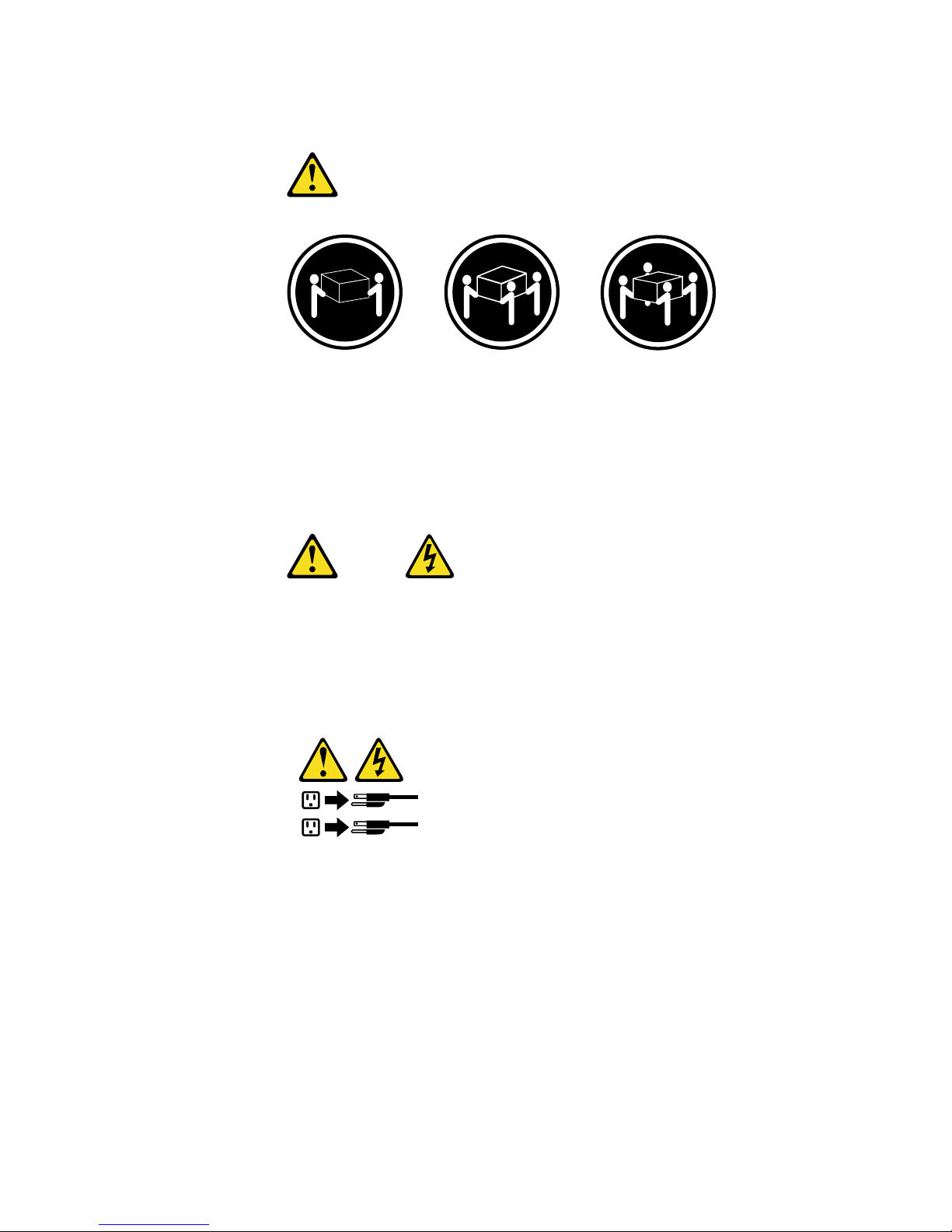
Statement 4
18 kg (37 lbs) 32 kg (70.5 lbs) 55 kg (121.2 lbs)
CAUTION:
Use safe practices when lifting.
Statement 5
CAUTION:
The power control button on the device and the power switch on the power supply do not
turn off the electrical current supplied to the device. The device also might have more than
one power cord. To remove all electrical current from the device, ensure that all power
cords are disconnected fro m the power source.
1
2
Page 10

viii IBM® xSeries 150 : User’s Reference
Page 11

© Copyright IBM Corp. 2000 ix
Contents
Safety . . . . . . . . . . . . . . . . . . . . . . . . . . . . . iii
Chapter 1.Introducing the IBM xSeries 1501
Features and specifications . . . . . . . . . . . . . . . . . . . . . . . . 1
Notices used in this book. . . . . . . . . . . . . . . . . . . . . . . . . . 3
What your IBM xSeries 150 offers. . . . . . . . . . . . . . . . . . . 3
Reliability, availability, and serviceability features . . . . 4
Server controls and indicators. . . . . . . . . . . . . . . . . . . . . . 6
Operator information panel . . . . . . . . . . . . . . . . . . . . . . . . 7
Chapter 2.Arranging your workspace . . . . 9
Comfort. . . . . . . . . . . . . . . . . . . . . . . . . . . . . . . . . . . . . . . . . 9
Glare and lighting . . . . . . . . . . . . . . . . . . . . . . . . . . . . . 9
Air circulation. . . . . . . . . . . . . . . . . . . . . . . . . . . . . . . . . 9
Electrical outlets and cable lengths. . . . . . . . . . . . . . 10
Chapter 3.Installing Options. . . . . . . . . . . 11
Major components of the xSeries 150 server. . . . . . . . . 11
System board . . . . . . . . . . . . . . . . . . . . . . . . . . . . . . . . . . . 12
System board options connectors . . . . . . . . . . . . . . . 12
System board internal cable connectors. . . . . . . . . . 14
System board external port connectors . . . . . . . . . . 14
System board switches and jumpers. . . . . . . . . . . . . 15
System board LED locations. . . . . . . . . . . . . . . . . . . . 18
Before you begin . . . . . . . . . . . . . . . . . . . . . . . . . . . . . . . . 19
System reliability considerations. . . . . . . . . . . . . . . . 19
Working inside a server with power on . . . . . . . . . . 20
Handling static sensitive devices. . . . . . . . . . . . . . . . 20
Safety information. . . . . . . . . . . . . . . . . . . . . . . . . . . . 20
Removing the cover, door, and bezel . . . . . . . . . . . . . . . 26
Removing the left-side cover (tower model) . . . . . . 26
Removing the cover (rack model) . . . . . . . . . . . . . . . 27
Removing the server door and bezel (tower model) 28
Removing the bezel (rack model) . . . . . . . . . . . . . . . 29
Working with adapters. . . . . . . . . . . . . . . . . . . . . . . . . . . 29
Adapter considerations. . . . . . . . . . . . . . . . . . . . . . . . 30
Installing an adapter . . . . . . . . . . . . . . . . . . . . . . . . . . 31
Installing internal drives . . . . . . . . . . . . . . . . . . . . . . . . . 33
Internal drive bays. . . . . . . . . . . . . . . . . . . . . . . . . . . . 33
Hot-swap drives. . . . . . . . . . . . . . . . . . . . . . . . . . . . . . 34
Non-hot-swap drives. . . . . . . . . . . . . . . . . . . . . . . . . . 34
Preinstallation steps (all bays) . . . . . . . . . . . . . . . . . . 35
Installing a hot-swap drive. . . . . . . . . . . . . . . . . . . . . 35
Replacing a drive in a hot-swap bay . . . . . . . . . . 36
Installing a non-hot-swap drive. . . . . . . . . . . . . . . . . 38
Installing memory modules. . . . . . . . . . . . . . . . . . . . . . . 40
Installing a microprocessor . . . . . . . . . . . . . . . . . . . . . . . 41
Installing or removing a power supply . . . . . . . . . . . . . 43
Adding a power supply . . . . . . . . . . . . . . . . . . . . . . . 44
Removing a power supply. . . . . . . . . . . . . . . . . . . . . 45
Replacing a fan assembly. . . . . . . . . . . . . . . . . . . . . . . . . 47
Installing the cover . . . . . . . . . . . . . . . . . . . . . . . . . . . . . . 49
Installing the cover (tower) . . . . . . . . . . . . . . . . . . . . 49
Installing the bezel and front door. . . . . . . . . . . . 50
Installing the cover (rack). . . . . . . . . . . . . . . . . . . . . . 51
Installing the bezel . . . . . . . . . . . . . . . . . . . . . . . . . 51
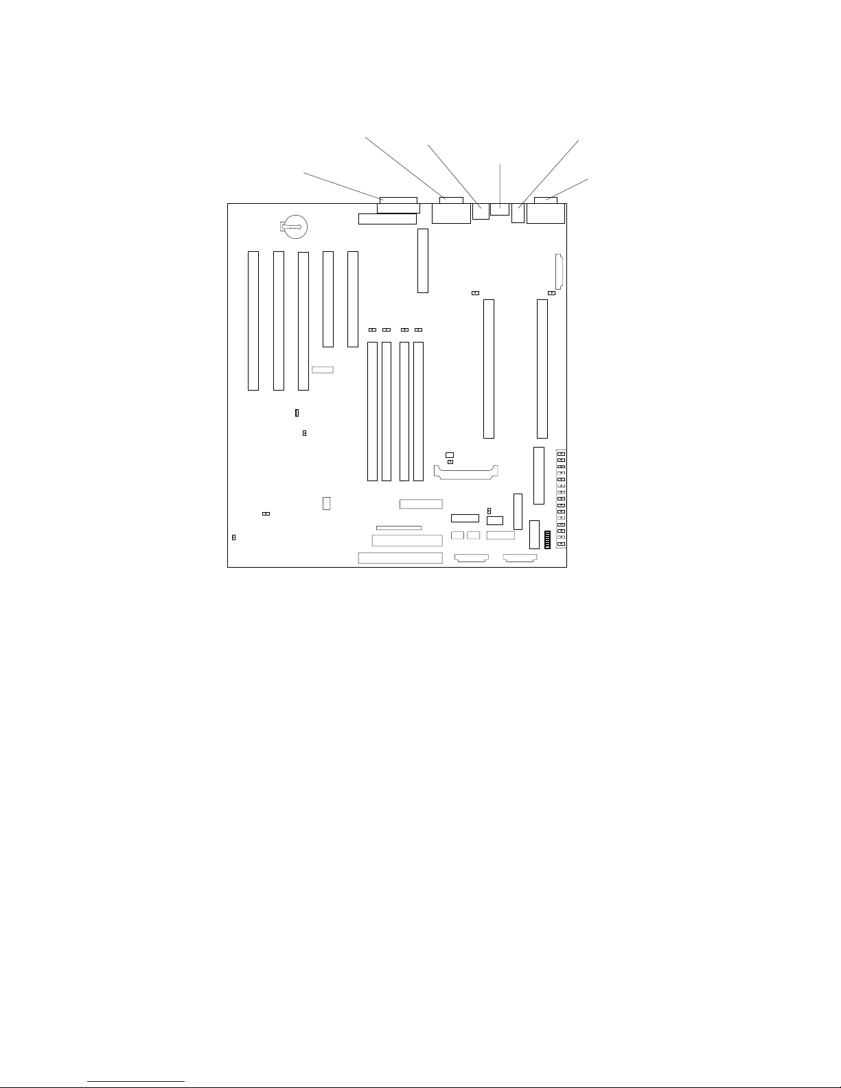
Connecting external options . . . . . . . . . . . . . . . . . . . . . . 53
Installation procedure . . . . . . . . . . . . . . . . . . . . . . . . . 53
I/O connector locations . . . . . . . . . . . . . . . . . . . . . . . . . . 53
Input/Output ports . . . . . . . . . . . . . . . . . . . . . . . . . . . . . 54
Parallel port. . . . . . . . . . . . . . . . . . . . . . . . . . . . . . . . . . 54
Viewing or changing the parallel-port assignments
54
Parallel port connector. . . . . . . . . . . . . . . . . . . . . . 54
Serial ports. . . . . . . . . . . . . . . . . . . . . . . . . . . . . . . . . . . 55
Vi ewi ng o r changing the serial-port assign m ent s 56
Serial-port connectors. . . . . . . . . . . . . . . . . . . . . . . 56
Universal Serial Bus ports. . . . . . . . . . . . . . . . . . . . . . 56
USB cables and hubs. . . . . . . . . . . . . . . . . . . . . . . . 57
USB-port connectors. . . . . . . . . . . . . . . . . . . . . . . . 57
Keyboard port. . . . . . . . . . . . . . . . . . . . . . . . . . . . . . . . 57
Auxiliary-device (pointing device) port. . . . . . . . . . 58
Video port . . . . . . . . . . . . . . . . . . . . . . . . . . . . . . . . . . . 58
SCSI ports . . . . . . . . . . . . . . . . . . . . . . . . . . . . . . . . . . . 59
SCSI cabling requirements. . . . . . . . . . . . . . . . . . . 59
Setting SCSI IDs. . . . . . . . . . . . . . . . . . . . . . . . . . . . 59
SCSI connector pin-number assignments . . . . . . 59
Ethernet port . . . . . . . . . . . . . . . . . . . . . . . . . . . . . . . . 61
Configuring the Ethernet controller. . . . . . . . . . . 61
Failover for redundant Ethernet. . . . . . . . . . . . . . 61
Ethernet port connector . . . . . . . . . . . . . . . . . . . . . 62
Advanced System Management ports . . . . . . . . . . . 63
Cabling the server . . . . . . . . . . . . . . . . . . . . . . . . . . . . . . . 63
Chapter 4.Solving Problems. . . . . . . . . . . 67
Diagnostic tools overview . . . . . . . . . . . . . . . . . . . . . . . . 67
POST . . . . . . . . . . . . . . . . . . . . . . . . . . . . . . . . . . . . . . . . . . 70
POST beep code descriptions . . . . . . . . . . . . . . . . . . . 70
POST beep codes . . . . . . . . . . . . . . . . . . . . . . . . . . . . . 72
POST error messages. . . . . . . . . . . . . . . . . . . . . . . . . . 73
Event/error logs. . . . . . . . . . . . . . . . . . . . . . . . . . . . . . 82
Small computer system interface messages. . . . . . . . . . 82
Diagnostic programs and error messages . . . . . . . . . . . 83
Text messages . . . . . . . . . . . . . . . . . . . . . . . . . . . . . . . . 84
Starting the diagnostic programs. . . . . . . . . . . . . . . . 84
Viewing the test log . . . . . . . . . . . . . . . . . . . . . . . . . . . 85
Diagnostic error message tables. . . . . . . . . . . . . . . . . 86
Recovering BIOS . . . . . . . . . . . . . . . . . . . . . . . . . . . . . . . . 94
Identifying problems using status LEDs . . . . . . . . . . . . 95
Light path diagnostics . . . . . . . . . . . . . . . . . . . . . . . . . 95
Power supply LEDs . . . . . . . . . . . . . . . . . . . . . . . . 95
Diagnostics panel . . . . . . . . . . . . . . . . . . . . . . . . . . 96
Light path diagnostics table . . . . . . . . . . . . . . . . . 97
Troubleshooting charts . . . . . . . . . . . . . . . . . . . . . . . . . . . 99
Troubleshooting the Ethernet controller. . . . . . . . . 105
Network connection problems . . . . . . . . . . . . . . 105
Ethernet controller troubleshooting chart. . . . . 106
Ethernet controller messages . . . . . . . . . . . . . . . . . . 107
Novell NetWare or IntraNetWare server OD I driver
messages. . . . . . . . . . . . . . . . . . . . . . . . . . . . . . . . . 107
Network driver interface specification 2.01 (OS/2)
driver messages. . . . . . . . . . . . . . . . . . . . . . . . . . . 109
NDIS 4.0 (Windows NT) driver messages. . . . . 111
UNIX messages. . . . . . . . . . . . . . . . . . . . . . . . . . . 111
Replacing the battery . . . . . . . . . . . . . . . . . . . . . . . . . . . 113
Getting help, service, and information. . . . . . . . . . . . . 115
Service support. . . . . . . . . . . . . . . . . . . . . . . . . . . . . . 116
Before you call for service. . . . . . . . . . . . . . . . . . . . . 117
Getting customer support and service . . . . . . . . . . 117
Using the World Wide Web . . . . . . . . . . . . . . . . . 117
Using electronic support services. . . . . . . . . . . . 118
Getting information by fax . . . . . . . . . . . . . . . . . 118
Page 12

x IBM® xSeries 150 User’s Reference
Getting help online. . . . . . . . . . . . . . . . . . . . . . . . 118
Getting help by telephone. . . . . . . . . . . . . . . . . . 119
Getting help around the world. . . . . . . . . . . . . . 120
Purchasing additional services . . . . . . . . . . . . . . . . 120
Enhanced PC support line . . . . . . . . . . . . . . . . . . 120
900-number oper ating system and hardware
support line . . . . . . . . . . . . . . . . . . . . . . . . . . . . . . 121
Network and server support line. . . . . . . . . . . . 121
Ordering support line services. . . . . . . . . . . . . . 121
Warranty and repair services . . . . . . . . . . . . . . . 121
Ordering publications . . . . . . . . . . . . . . . . . . . . . . . . 122
Chapter 5.Using the Recovery and
Supplementary CDs. . . . . . . . . . . . . . . . 123
Using the Recovery Enablement Diskette and Recovery
CD . . . . . . . . . . . . . . . . . . . . . . . . . . . . . . . . . . . . . . . . . . . 123
Using the Supplementary CD . . . . . . . . . . . . . . . . . . . . 124
Chapter 6.Appliance Configuration
Programs . . . . . . . . . . . . . . . . . . . . . . . . 127
Universal Manageability Services. . . . . . . . . . . . . . . . . 127
System Requirements . . . . . . . . . . . . . . . . . . . . . . . . 128
Starting UM Services . . . . . . . . . . . . . . . . . . . . . . . . . 128
IBM Advanced Appliance Configuratio n Utilit y . . . 129
The Advanced Appliance Configuration Utility Agent
130
The Advanced Appliance Configuration Utility
Console . . . . . . . . . . . . . . . . . . . . . . . . . . . . . . . . . . . . . . . 130
Discovering xSeries Appliances . . . . . . . . . . . . . 131
Using Families and Groups in the Tree View. . 132
Launching UM Services. . . . . . . . . . . . . . . . . . . . 135
Terminal Services Client. . . . . . . . . . . . . . . . . . . . . . . . . 136
Appendix A. Rack Installation Instructions.
139
Appendix B. Product warranties and
notices . . . . . . . . . . . . . . . . . . . . . . . . . . 143
Warranty Statements. . . . . . . . . . . . . . . . . . . . . . . . . . . . 143
IBM Statement of Limited Warranty for United States,
Puerto Rico, and Canada (Part 1 - General Terms) 143
IBM Statement of Warranty Worldwide except
Canada, Puerto Rico, Turkey, United States (Part 1 –
General Terms) . . . . . . . . . . . . . . . . . . . . . . . . . . . . . . 146
Part 2 - Worldwide Country-Unique Terms . . . . . . 149
End-User License Agreement: Microsoft Windows
Powered Operating System . . . . . . . . . . . . . . . . . . . . . . 153
End-User License Agreement: Microsoft Windows
Services for NetWare Version 5.0. . . . . . . . . . . . . . . . . . 156
Notices. . . . . . . . . . . . . . . . . . . . . . . . . . . . . . . . . . . . . . . . 159
Edition Notice . . . . . . . . . . . . . . . . . . . . . . . . . . . . . . . 159
Year 2000 readiness and instructions. . . . . . . . . . . . 160
Trademarks . . . . . . . . . . . . . . . . . . . . . . . . . . . . . . . . . 160
Important notes . . . . . . . . . . . . . . . . . . . . . . . . . . . . . 161
Electronic emission notices . . . . . . . . . . . . . . . . . . . . . . 161
Federal Communications Commission (FCC)
Statement. . . . . . . . . . . . . . . . . . . . . . . . . . . . . . . . . . . 161
Industry Canada Class A emission compliance
statement . . . . . . . . . . . . . . . . . . . . . . . . . . . . . . . . . . . 162
Australia and New Zealand Class A statement. . . 162
United Kingdom telecommunications safety
requirement. . . . . . . . . . . . . . . . . . . . . . . . . . . . . . . . . 162
European community directive conformance
statement . . . . . . . . . . . . . . . . . . . . . . . . . . . . . . . . . . . 162
Taiwan electrical emission statement . . . . . . . . . . . 163
Japanese Voluntary Control Council for Interference
(VCCI) statement . . . . . . . . . . . . . . . . . . . . . . . . . . . . 163
Power cords . . . . . . . . . . . . . . . . . . . . . . . . . . . . . . . . . . . 163
Index . . . . . . . . . . . . . . . . . . . . . . . . . . . . . 165
Page 13

© Copyright IBM Corp. 2000 1
Chapter 1. Introducing the IBM xSeries 150
Your IBM
®
xSeries150 server is a high-performance, symmetric
multiprocessing (SMP) server. It is ideally suited for networking environments that
require superior microprocessor performance, efficient memory management,
flexibility, and large amounts of reliable data storage.
Your IBM xSeries 150 server comes with a three-year limited warranty and 90-Day
IBM Start Up Support. If you have access to the World Wide Web, you can obtain upto-date information about your xS eries 150 model and other IBM server products at
the following World Wi de Web address:
http://www.ibm.com/pc/us/netfinity/
Your server serial number and model number are located on labels on the rear of the
server and on the front below the bezel.
Note: The information label containing the serial number, machine type, model
number, and agency marks for your server is located as follows:
Tower model On the bottom of the server
Rack model On the side of the server
For service, assistance, or additional information on 90-Day IBM Start Up Support
and the World Wide Web, see “Getting help, service, and information” on page 115.
Features and specifications
Table 1 on page 2 provides a summary of the features and specifications for your
xSeries 150 server.
Page 14

2 IBM® xSeries 150 : User’s Reference
Table 1. Features and Specifications
Microprocessor:
• 1 or 2 Intel® Pentium® III
microprocessors with
MMX™ technology and
SIMD extensions, depend ing
on model
• 256 KB Level-2 cache (min.)
• Supports up to two
microprocessors
Memory:
• Standard: 256 MB or 1 GB,
depending on model
• Maximum: 4 GB
• Type: 133 MHz, ECC,
SDRAM, Registered DIMMs
• Slots: 4 dual inline slots
Drives standard:
• 3 or 6 Hard Disk Drives,
depending on model
• Diskette: 1.44 MB
• CD-ROM: 40X IDE
Expansion bays:
• Hot-swap: six slim high or
three half high
• Non-hot-swap: Three 5.25inch (one used by CD-ROM
drive)
PCI expansion slots:
• Three 33 MHz/6 4-b it
• Two 33 MHz/32-bit
Power supplies:
250 watt (115-230 Vac)
• Standard: One
• Maximum: Three, only with
optional power backplane
that enables multiple power
supplies and hotswappability
Video:
• S3 video controller (integrated on
system board)
• Compatible with SVGA and VGA
• 8 MB SDRAM video memory
Size (Rack Model 5U)
• Height: 220 mm (8.7 in.)
• Depth: 630 mm (24.8 in.)
• Width: 440 mm (17.3 in.)
• Weight: approximately 35.38 Kg (78
lb.) when fully configured
Size (Tower Model)
• Height: 440 mm (17.3 in.)
• Depth: 660 mm (26.0 in.)
• Width: 220 mm (8.7 in.)
• Weight: approximately 36.74 Kg (81
lb.) when fully configured
Integrated functions:
• Netfinity Advanced System
Management processor
• ServeRAID 4L/4H PCI adapter
• Dual channel Ultra3 SCSI controller
• One integrated 10BASE-T/100 BA SE-
TX AMD Ethernet controller
• 1 or 3 Netfinity 10/100 Ethernet
Adapter 2s, depending on model
• Two serial ports
• One parallel port
• Two Universal Serial Bus (USB) ports
• Keyboard port
• Mouse port
• Video port
Acoustical noise emissions:
• Sound power, idling: 6.0 bel
maximum
• Sound power, operating: 6.0 bel
maximum
• Sound pressure, operating: 45 dBa
maximum
Environment:
• Air temperature:
— Server on: 10 to 35 C
(50.0 to 95.0 F).
Altitude: 0 to 914 m
(2998.7 ft.)
— Server on: 10 to 32 C
(50.0 to 89.6 F).
Altitude: 914 m (2998.7
ft.) to 2133 m (6998.0 ft.)
— Server off: 10 to 43 C
(50.0 to 109.4 F).
Maximum altitude: 2133
m (6998.0 ft.)
• Humidity:
— Server on: 8% to 80%
— Server off: 8% to 80%
Heat output:
Approximate heat output in British
Thermal Units (BTU) per hour
• Minimum configuration: 683
BTU (200 watts)
• Maximum configuration:
2048 BTU (600 watts)
Electrical input:
• Sine-wave input (50-60 Hz)
required
• Input voltage low range:
— Minimum: 100 V ac
— Maximum: 127 V ac
• Input voltage high range:
— Minimum: 200 V ac
— Maximum: 240 V ac
• Input kilovolt-amperes
(kVA) approximately:
— Minimum: 0.08 kVA
— Maximum: 0.52 kVA
Page 15

Chapter 1. Introducing the IBM xSeries 150 3
Notices used in this book
This information product contains notices that relate to a specific topic. The Caution
and Danger notices also appear in the multilingual safety booklet that came with your
xSeries product. Each notice is numbered for easy reference to the corresponding
notices in the safety booklet.
The notice definitions are as follows:
• Notes:These notices provide important tips, guidance, or advice.
• Attention:These notices indicate possible damage to programs, devices, or data.
An attention notice is placed just before the instruction or situation in which
damage could occur.
• Caution:These notices indicate situations that can be potentially hazardous to
you. A caution notice is placed just before descriptions of potentially hazardous
procedure steps or situations.
• Danger: These notices indicate situations that can be potentially lethal or
extremely hazardous to you. A danger notice is placed just before descriptions of
potentially lethal or extremely hazardous procedure steps or situations.
What your IBM xSeries 150 offers
The unique design of your server takes advantage of advancements in symmetric
multiprocessing (SMP), data storage, and memory management. Your server
combines:
• Impressive performance using an innovative approach to SMP
Your server supports up to two Pentium III microprocessors. Your server comes
with one microprocessor installed; you can install an additional microprocessor
to enhance performance and provide SMP capability.
• Large data-storage and hot-swap capabilities
All models of the server support up to six hot-swap hard disk drives. This hot-
swap feature enables you to remove and replace hard disk drives without
turning off the server.
• Redundant power capabilities
The standard 250-watt power supply in your server can handle a load of up to
250 watts. By replacing the power backplane with the power backplane option,
you can install a second, optional power supply. This provides a full 500 watts
of power. If the average load on your server is less than 250 watts and a problem
occurs with one of the power supplies, the other power supply can handle the
load (redundant power). If the average load on your server is greater than 250
watts, and you have installed a second power supply, you can install a third,
optional power supply to provide redundancy.
The NON light emitting diode (LED) on the system board is lit when the power
load is 250 watts or greater with two power supplies, or when the power load is
500 watts or greater with three power supplies.
• Large system memory
The memory bus in your server supports up to 4gigabytes (GB) of system
memory. The memory controller provides error correcting code (ECC) support
for up to four industry standard PC133, 3.3 V, 168-pin, 8-byte, registered,
synchronous-dynamic-random access memory (SDRAM) dual inline memory
modules (DIMMs).
Page 16

4 IBM® xSeries 150 : User’s Reference
• System-management capabilities
Y our server comes with a Netfinity Advanced System Management Processor on
the system board. This processor enables you to manage the functions of the
server locally and remotely. The Netfinity Advanced System Management
Processor also provides system monitoring, event recording, and dial-out alert
capability.
Note: The Netfinity Advanced System Managem e nt Processor is sometimes
referred to as the service processor.
• Integrated network environment support
Your server comes with an Ethernet controller on the system board. This
Ethernet controller has an interface for connecting to 10-Mbps or 100-Mbps
networks. The server automatically selects between 10BASE-T and 100BASE-TX.
The controller provides full-duplex (FDX) capability , which allows simultaneous
transmission and reception of data on the Ethernet local area network (LAN).
• Redundant network-interface card
The addition of an optional, redundant network interface card (NIC) provides a
failover capability to a redundant Ethernet connection. If a problem occurs with
the primary Ethernet connection, all Ethernet traf fic associated with this primary
connection is automatically switched to the redundant NIC. This switching
occurs without data loss and without user intervention.
• Optional digital linear tape drive
The addition of an optional digital linear tape drive (DLT) allows quick backup
of large amounts of data.
Reliability, availability, and serviceability features
Three of the most important features in server design are reliability, availability, and
serviceability (RAS). These factors help to ensure the integrity of the data stored on
your server; that your server is available when you want to use it; and that should a
failure occur, you can easily diagnose and repair the failu re with mi nimal
inconvenience.
The following is an abbreviated list of the RAS features that your server supports.
• Menu-driven setup, system configuration, RAID configuration, and diagnostic
programs
• Power-on self-test (POST)
• Integrated Netfinity Advanced System Management Processor
• Predictive failure alerts
• Remote system problem-analysis support
• Power and temperature monitoring
• Hot-swap drive bays
• Error codes and messages
• System error logging
• Upgradable BIOS, diagnostics, and Netfinity Advanced System Management
Processor code
• Automatic restart after a power failure
• Parity checking on the PCI buses
• CRC checking on the SCSI buses
• Error checking and correcting (ECC) memory
• Redundant hot-swap power supply option
• Redundant Ethernet capabilities (with optional adapter)
• Vi tal Product Data (VP D) on system board, power backplane, SCSI backplane,
and each power supply
Page 17

Chapter 1. Introducing the IBM xSeries 150 5
• Operator information panel
• Diagnostic LEDs on the system board
• Customer support center 24 hours per day 7 days a week
1
1.Service availability will vary by country. Response time will vary depending on the number and nature of incoming calls.
Page 18
6 IBM® xSeries 150 : User’s Reference
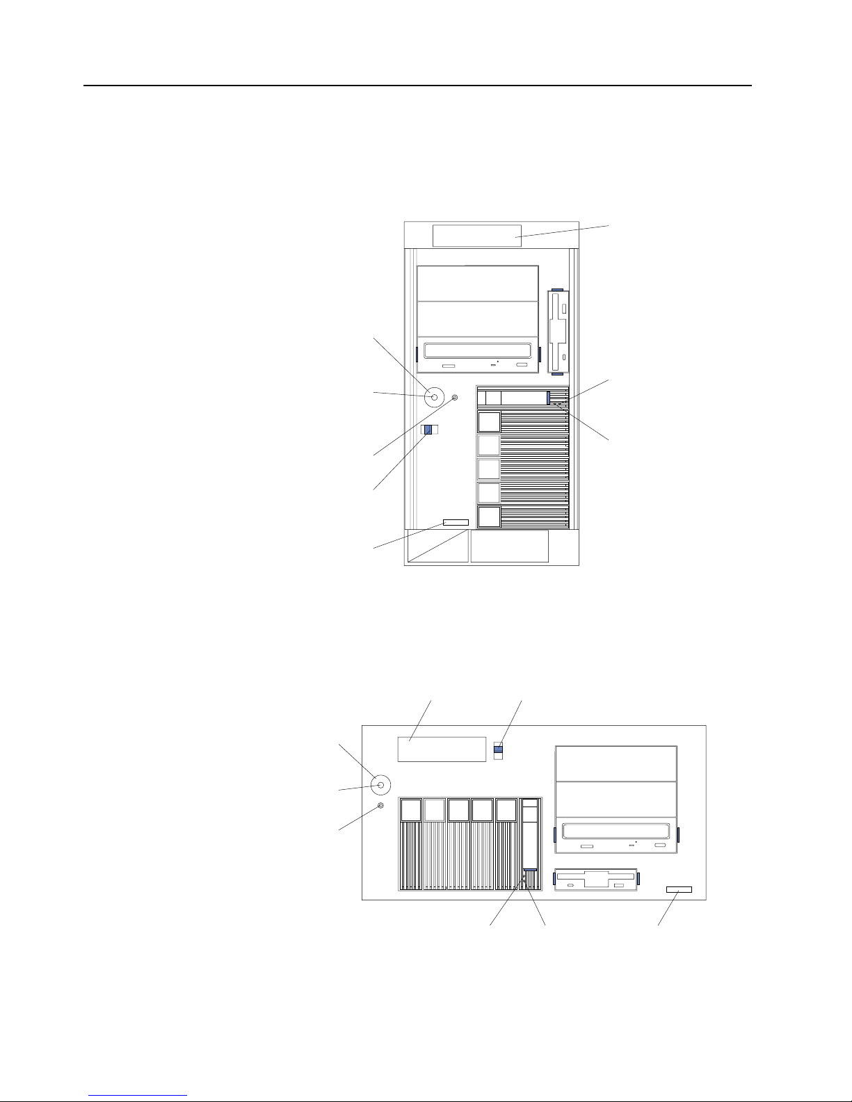
Server control s a nd indicators
The following illustrations show the controls and indicators on the front of the server.
Power control button: Press this button to manually turn the server on or off.
Tower mod el
Rack model
Hard disk
drive activity
light (green)
Hard disk
drive status
light (amber)
Reset
button
Power
control
button
Power control
button shield
(if installed)
Cover
release
latch
Serial
number
Operator
information
panel
Hard disk
drive activity
light (green)
Hard disk
drive status
light (amber)
Reset button
Power control
button
Cover
release
latch
Operator
information
panel
Power control
button shield
(if installed)
Serial
number
Page 19
Chapter 1. Introducing the IBM xSeries 150 7
Power control button shield: You can install this circular disk over the power control
button to prevent accidental manual power-off. This disk is provided with your
server.
Reset button:Press this button to reset the server and run the power-on self-test
(POST).
Operator information panel:The lights on this panel give status information for your
server.
Cover release latch:Slide this lever to release the cover.
Serial number:This number uniquely identifies your server.
Hard disk drive status light: Each of the hot-swap drives has a hard disk drive status
light. When this amber light is on continuously, the drive has failed.
Hard disk drive activity light: Each of the hot-swap drives has a hard disk drive
activity light. When this green light is flashing, the controller is accessing the drive.
If a ServeRAID adapter is installed and this light flashes slowly (one flash per second),
the drive is being rebuilt. When the light flashes rapidly (three flashes per second),
the controller is identifying the drive.
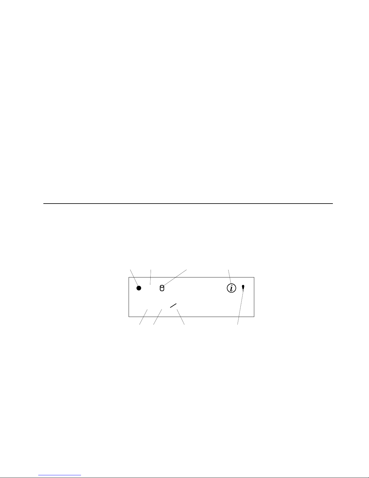
Operator information panel
The following illustration shows the location of the status lights on the operator
information panel on the front of the server (see “Server controls and indicators” on
page 6).
Power-on light
This green LED lights when system power is present in the server. When this
light flashes, the server is in standby mode (the sys tem power supply is
turned off and AC current is present). If this light is not on, the power cord is
not connected, the power supply has failed, or this LED has failed.
POST complete light
This green LED lights when the server completes the power-on self-test
(POST) without any errors.
SCSI hard disk drive in-use light
This green LED lights when there is activity on a hard disk drive.
OK
100
MB
LINK
OK
TX
RX
Power-on
light
POST
complete light
SCSI hard
disk drive
in-use light
Information
light
System
error light
Ethernet
speed light
Ethernet link
status light
Ethernet transmit/
receive activity light
Page 20

8 IBM® xSeries 150 : User’s Reference
Information light
This amber LED lights when the information log contains information about
certain conditions in your server that might affect performance. For example,
the light will be on if your server has multiple power supplies and does not
have redundant power. An LED on the diagnostic panel on the system board
will also be on.
System error light
This amber LED lights when a system error occurs. An LED on the
diagnostic panel on the system board will also be on to further isolate the
error. Refer to the "Problem solving" section of the User’s Reference on the IBM
xSeries Documentation CD for detailed information on using the diagnostic
panel (light path diagnostics).
Ethernet speed light
This green LED lights when the Ethernet LAN speed is 100 Mbps.
Ethernet link status light
This green LED lights when there is an active connection on the Ethernet
port.
Ethernet transmit/receive activ it y light
This green LED lights when there is transmit or receive activity to or from the
server.
Page 21

© Copyright IBM Corp. 2000 9
Chapter 2. Arranging your workspace
To get the most from your server, arrange both the equipment you use and your work
area to suit your needs and the kind of work you do. Your comfort is of foremost
importance, but light sources, air circulation, and the location of electrical outlets also
can affect the way you arrange your workspace.
Comfort
Although no single working position is ideal for everyone, here are a few guidelines
to help you find a position tha t suits you best.
Sitting in the same position for a long time can cause fatigue. A good chair can make a
big difference. The backrest and seat should adjust independently and provide good
support. The seat should have a curved front to relieve pressure on the thighs. Adjust
the seat so that your thighs are parallel to the floor and your feet are either flat on the
floor or on a footrest.
When using the keyboard, keep your for earms parallel to the floor and your wrists in
a neutral, comfortable position. Try to keep a light touch on the keyboard and your
hands and fingers relaxed. You can change the angle of the keyboard for maximum
comfort by adjusting the position of the keyboard feet.
Adjust the monitor so the top of the screen is at, or slightly below, eye level. Place the
monitor at a comfortable viewing distance, usually 51 to 61 cm (20 to 24 in.), and
position it so you can view it without having to twist your body. Also position other
equipment you use regularly, such as the telephone or a mouse, within easy reach.
Glare and lighting
Position the monitor to minimize glare and reflections from overhead lights,
windows, and other light sources. Even reflected light from shiny surfaces can cause
annoying reflections on your monitor screen. Place the monitor at right angles to
windows and other light sources, when possi ble. Red uce overhead lighting, if
necessary, by turning off lights or using lower wattage bulbs. If you in stall the
monitor near a window, use curt ains or blinds to block the sunlight. You might have
to adjust the Brightness and Contrast controls on the mon itor as the room lighting
changes throughout the day.
Where it is impossible to avoid reflections or to adjust the lighting, an antiglare filter
placed over the screen might be helpful. However, these filters might affect the clarity
of the image on the screen; try them only after you have tried all other methods of
reducing glare.
Dust buildup compounds problems that are associated with glare. Remember to clean
your monitor screen periodically using a soft cloth that is moistened with a
nonabrasive liquid glass cleaner.
Air circulation
Your server and monitor produce heat. Your server has one or more fans that pull in
fresh air and force out hot air . The monitor lets hot air escape through vents. Blocking
the air vents can cause overheating, which might result in a malfunction or dama ge.
Page 22

10 IBM® xSeries 150 : Use r’s Reference
Place the server and monitor so that nothing blocks the air vents; usually, 15 cm (6
inches) of air space is sufficient. Also, make sure that the vented air is not blowing on
someone else.
Electrical outlets and cable lengths
The location of electrical outlets and the length of power cords and cables that connect
to the monitor, printer, and other devices might determine the final placement of your
server.
When arranging your workspace:
• Avoid the use of extension cords. When possible, plug the server power cords
directly into electrical outlets.
• Keep power cords and cables neatly routed away from walkways and other
areas where they might get kicked accidentally.
For more information about power cords, refer to the power cord information in this
on-line publication.
Page 23

© Copyright IBM Corp. 2000 11
Chapter 3. Installing Options
This chapter provides instructions to help you add options to your server. Some
option-removal instructions are provided, in case you need to remove one option to
install another.
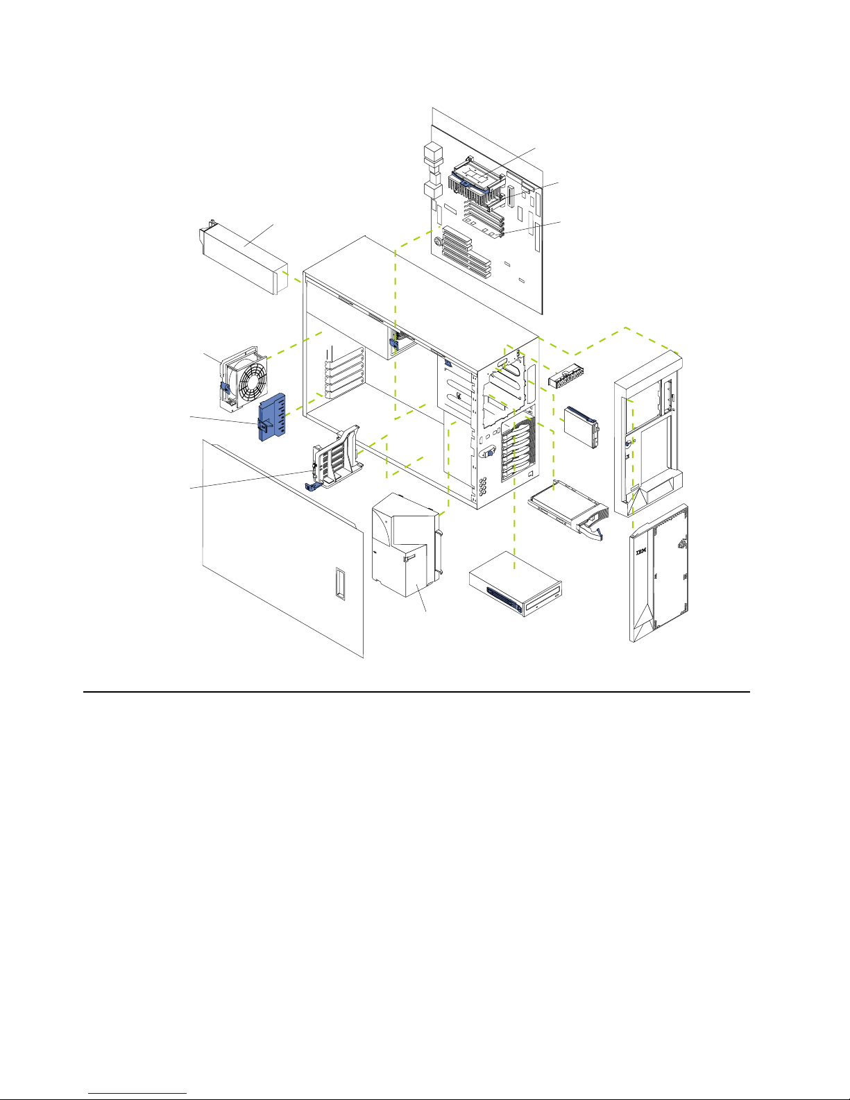
Major components of the xSeries 150 server
The orange color on components and labels in your server identif ies hot-swap
components. This means that you can install or remove the component while the
system is running, provided that your system is configured to support this function .
For complete information about installing or removing a hot-swap component, see
the detailed procedures in this chapter.
The blue color on components and labels indicates touch points where a component
can be gripped, a latch moved, and so on.
The following illustration shows the locations of major components in your server.
Note: The illustrations in this document might differ slightly from your hardware.
Page 24
12 IBM® xSeries 150 : Use r’s Reference
System board
The illustrations in the following sections show the components on the system board.
System board options connectors
The following illustration identifies system-board connectors for user-installable
options.
Note: The illustrations in this document might differ slightly from your hardware.
Terminator card
Microprocessor
Memory module
Pow er supply
Fan
Adapter
retention
bracket
Adapter
support
bracket
Fan (blower)
Page 25
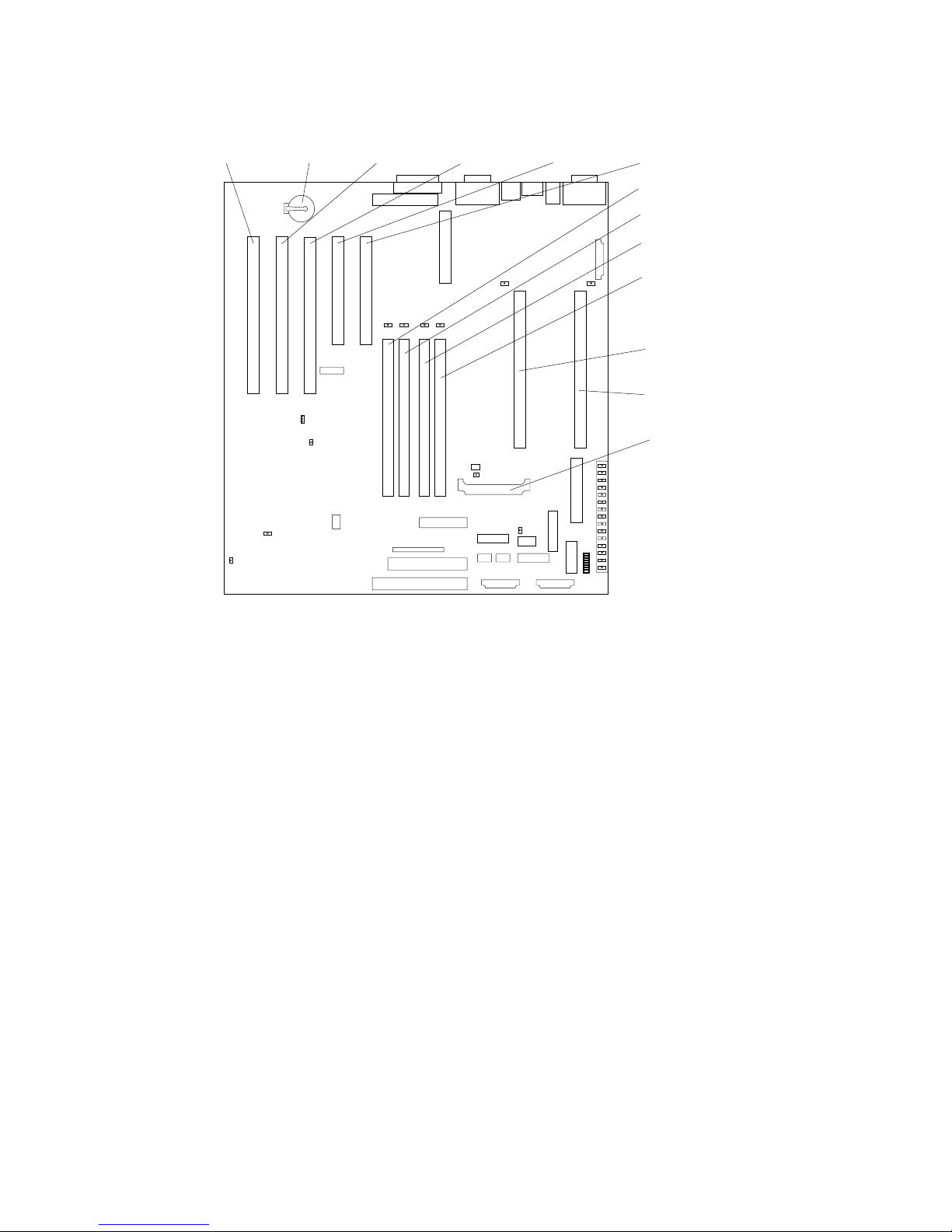
Chapter 3. Installing Options 13
PCI slot 5
64-bit
33 MHz (J44)
PCI slot 4
64-bit
33 MHz (J39)
PCI slot 3
64-bit
33 MHz (J34)
PCI slot 2
32-bit
33 MHz (J32)
PCI slot 1
32-bit
33 MHz (J27)
Battery
DIMM 1 (J23)
DIMM 2 (J21)
DIMM 3 (J19)
DIMM 4 (J18)
Microprocessor 2 (U17)
Microprocessor 1 (U3)
V oltage regulator
module (VRM2) (U29)
Page 26
14 IBM® xSeries 150 : Use r’s Reference
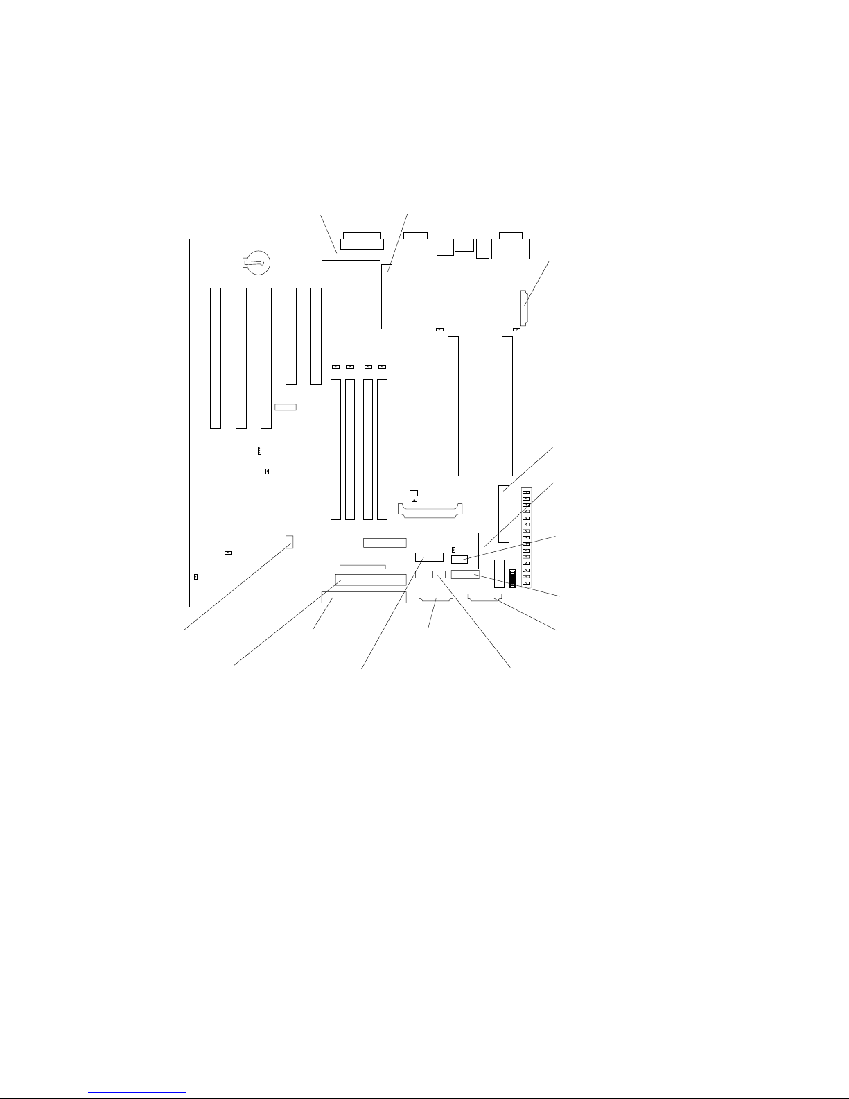
System board internal cable connectors
The following illustration id entifies system-board connectors for internal cables.
Note: The illustrations in this document might differ slightly from your hardware.
System board external port connectors
The following illustration identifies system-board connectors for external devices.
Note: The illustrations in this document might differ slightly from your hardware.
SCSI
channel B (J29)
SCSI
channel A (J17)
Main pow e r (J 4 )
Pow er-signal (J51)
DASD (SCSI) system
management (J5)
Pow er-system managem ent
and signal (J12)
Diskette (J26)
IDE (J31)
On-Off/Reset
panel
(
J38
)
Fan 2 (J60)
Operator information
panel
(
J50
)
Fan 1 (unused) (J59)
Advanced System
Management
RS-485 (J40)
Fan 3 (J35)
Page 27
Chapter 3. Installing Options 15
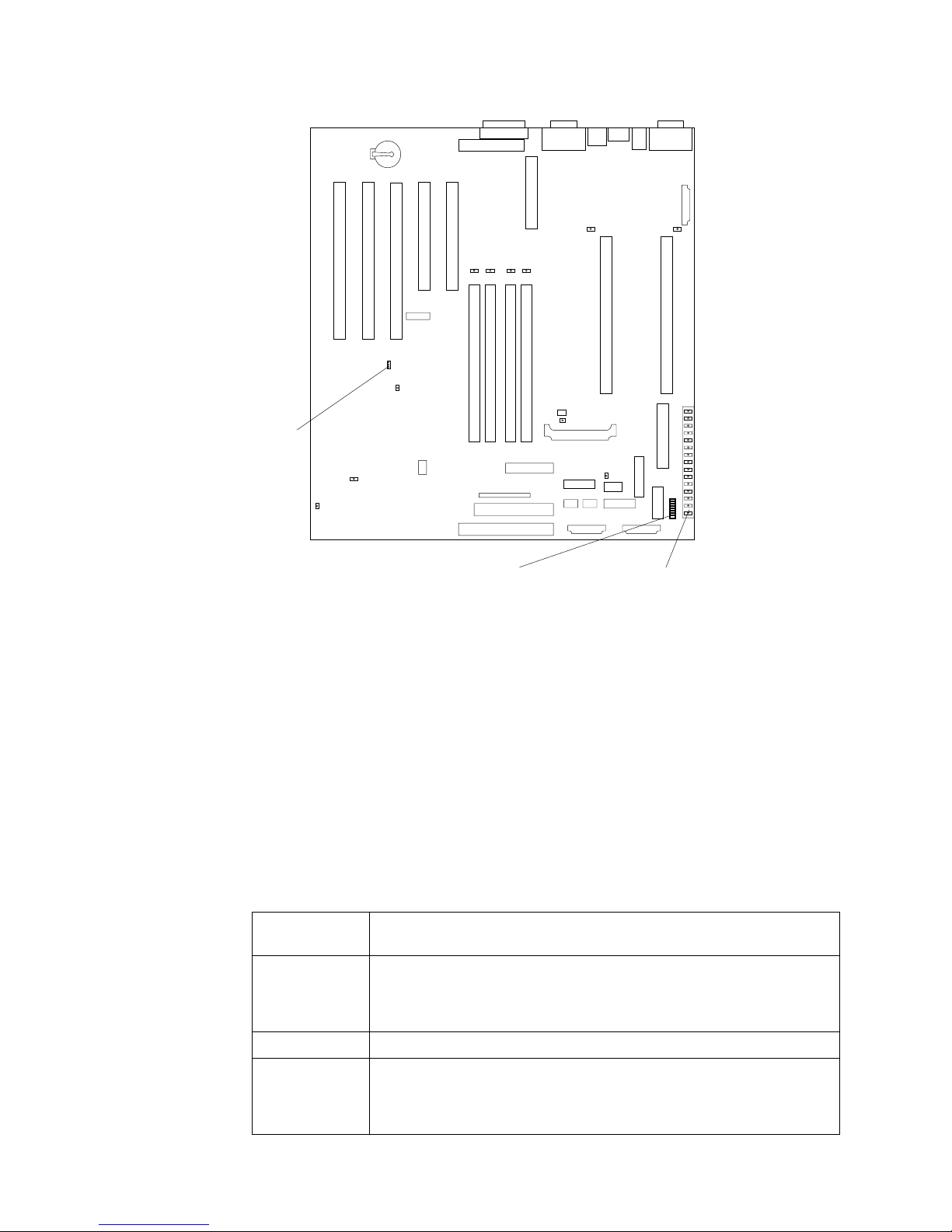
System board switches and jumpers
The following illustration identifies the switches and jumpers on the system board.
Note: The illustrations in this document might differ slightly from your hardware.
Parallel port (J22)
Video/Advanced
System Management
Processor port (J13) USB ports (J11)
Ethernet port (J9)
Keyboard/mouse port (J6)
Serial ports (J3)
Page 28
16 IBM® xSeries 150 : Use r’s Reference
System board jumper blocks
Any jumper blocks on the system board that are not shown in the illustration are
reserved. For normal operation of the system, no jumpers should be installed on any
of the jumper blocks. See “Recovering BIOS” on page 94 for information about the
boot block jumper.
System board switch block
The switch block contains microswitches 1-8. As pictured in this illustration, switch 8
is at the top of the switch block and switch 1 is at the bottom. The Off position for each
switch is the side nearer the diagnostics panel.
The following table describes the function for each switch.
Table 2. Switches 1-8
Switch
number
Switch
description
8 Bypass power-on password. The default setting is Off.
When toggled to the On position and back to Off, clears the power-on
password, if one is set.
7 Reserved. The default setting is Off.
6 Clock frequency selection. The default setting is Off.
When On, sets the host bus speed to 100 MHz. When Off, the host bus
speed is 133 MHz.
Boot block
jumper (J37)
System board
switch block (SW1)
Diagnostics
panel
Page 29
Chapter 3. Installing Options 17
5 Power-on override. The default setting is Off (disabled).
When On, overrides the power-on switch and for c es power -on mode. The
system will always boot without the use of the power-on switch.
4 Reserved.
3 Reserved.
2 Reserved.
1 Reserved.
Table 2. Switches 1-8
Switch
number
Switch
description
Page 30
18 IBM® xSeries 150 : Use r’s Reference
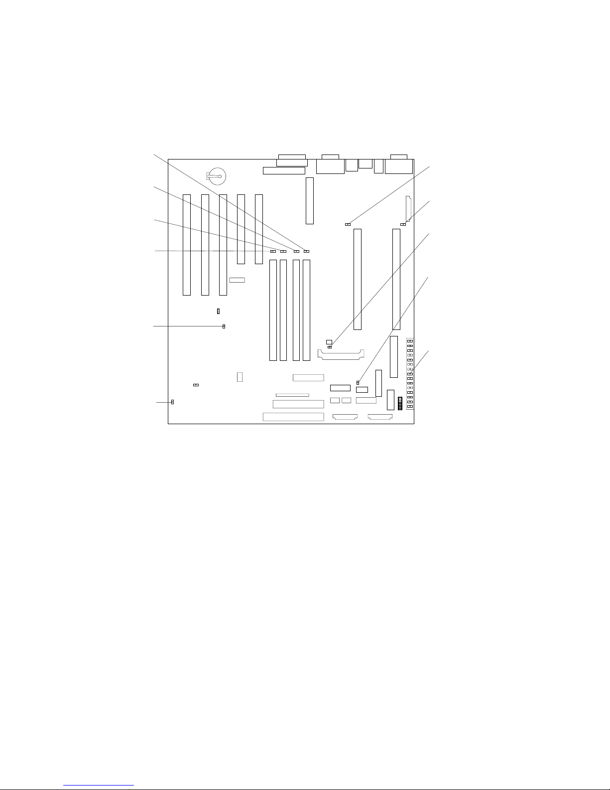
System board LED locations
The following illustration id entifies system-board LEDs. You might need to refer to
this figure when troubleshooting a problem.
Note: The illustrations in this document might differ slightly from your hardware.
Note: The power-on indicator (CR56) lights when system power is present in the
server. When this light flashes, the server is in standby mode (the system
power supply is turned off and current is present).
Diagnostics panel LED s:
PS1 Power supply 1 failure.
PS2 Power supply 2 failure.
PS3 Power supply 3 failure.
NON Non-redundant power.
OVER Overspec. The system has exceeded the power capabilities of the installed
power supply units.
NMI Non-maskable-interrupt occurred.
TEMP System temperature exceeded maximum rating.
FAN A fan failed or is operating slowly.
MEM Memory failure. One or more memory DIMMS have failed.
CPU Microprocessor failure. One or both microprocessors have failed.
PCI A Error on PCI channel A or system board.
Microprocessor 2
failure (CR 7 )
Microprocessor 1
failure (CR 1 )
V oltage regulator module
(VRM2) fa ilu re (CR16)
Integrated voltage regulator
(VRM1) fa ilu re (CR4)
Diagnostics panel
DIMM 4
failure (CR 2 0)
DIMM 3
failure (CR 1 8)
DIMM 2
failure (CR 2 8)
DIMM 1
failure (CR 2 1)
Power-on
indicator (CR56)
Advanced System
Management Processor
error (CR70)
Page 31

Chapter 3. Installing Options 19
Note: PCI bus A is often referred to as PCI bus 0.
PCI B Error on PCI channel B or system board.
Note: PCI bus B is often referred to as PCI bus 1.
VRM Error on voltage regulator module or on integrated voltage regulator.
DASD1 A hot-swap disk drive, backplane, or other part of SCSI channel A has failed.
DASD2 A SCSI device on SCSI channel B has failed.
Before you begin
Before you begin to install options in your se rver, read the following information:
• Become familiar with the safety and handling guidelines specified under
“Handling static sensitive devices” on page 20, and read the saf ety stat emen ts in
“Safety information” on page 20. These guidelines will help you work safely
while working with your server or options.
• You do not need to turn off the server to install or replace hot-swap power
supplies, or hot-swap drives.
• The orange color on components and labels in your server indicates hot-swap
components. This means that you can install or remove the component while the
system is running, provided that your system is configured to support this
function. For complete details about installing or removing a hot-swap
component, see the information provided in this chapter.
• The blue color on components and labels identifies touch points where a
component can be gripped, a latch moved, and so on.
• Make sure that you have an adequate number of properly grounded electrical
outlets for your server, monitor, a nd any other options that you intend to install.
• Back up all important data before you make changes to disk drives.
• Have a small, flat-blade screwdriver available.
• For a list of supported options for your server, refer to
http://www.ibm.com/pc/us/compat on the World Wide Web.
System reliability considerations
To help ensure proper cooling and system reliability, make sure:
• Each of the drive bays has either a drive or a filler panel installed.
• Each of the power supply bays has either a power supply or a filler panel
installed.
• The cover is in place during normal operations, or is r emoved for no longer than
30 minutes while the server is operating.
Note: The front door (tower model) can be removed permanently without
affec t in g system reli a b i li t y.
• There is space around the server to allow the server cooling system to work
properly.
— On a tower model, leave about 127 mm (5 in.) of s pace around the front and
rear of the server.
— On a rack model, refer to the documentation that comes with the rack.
• A r emoved hot-swap drive is replaced within two minutes of removal.
Page 32

20 IBM® xSeries 150 : Use r’s Reference
• Cables for optional adapters are routed according to the instructions provided
with the adapters.
• A failed fan is replaced within 48 hours.
Working inside a server with power on
Your server is designed to operate safely while turned on with the cover removed.
Follow these guidelines when you work inside a server that is turned on:
• Avoid loose-fitting clothing on your forearms. Button long-sleeved shirts before
working inside the server; do not wear cuff links while you are working inside
the server.
• Do not allow your necktie or scarf to hang inside the server.
• Remove jewelry, such as bracelets, rings, necklaces, and lo ose-fitting wrist
watches.
• Remove items from your shirt pocket (such as pens or pencils) that could fall
into the server as you lean over it.
• Take care to avoid dropping any metallic objects, such as paper clips, hair pins,
or screws, into the server.
Handling static sensitive devices
When you handle Electrostatic Discharge-Sensitive devices (ESD), take precautions to
avoid damage from static electricity. For details on handling these devices, refer to the
following Web site and use a search term of ESD: http://www.ibm.com/
Safety information
Before installing this product, read the Safety Information book .
Antes de instalar este produto, leia o Manual de Informações sobre Segurança.
Læs hæftet med sikkerhedsforskrifter, før du installerer dette produkt.
Lue Safety Information -kirjanen, ennen kuin asennat tämän tuotteen.
Pred instalací tohoto produktu si prectete prírucku bezpecnostních instrukcí.
Page 33

Chapter 3. Installing Options 21
Avant de procéder à l'installation de ce produit, lisez le manuel Safe ty Information.
Vor Beginn der Installation die Broschüre mit Sicherheitshinweisen lesen.
Prima di installare questo prodotto, leggere l'opuscolo contenente le informazioni
sulla sicurezza.
Lees voordat u dit product installeert eerst het boekje met veiligheidsvoorschriften.
Les heftet om sikkerhetsinformasjon (Safety Information) før du installerer dette
produktet.
Antes de instalar este produto, leia o folheto Informações sobr e Segurança.
Przed zainstalowaniem tego produktu należy przeczytać broszurę Informacje Dotyczące
Bezpieczeństwa.
Перед установкой продукта прочтите брошюру по технике безопасности
(Safety Information).
Pred inštaláciou tohto produktu si pre ítajte Informa nú brožúrku o bezpe nosti.
Page 34

22 IBM® xSeries 150 : Use r’s Reference
Antes de instalar este producto, lea la Información de Seguridad.
Läs säkerhetsinformationen innan du installerar den här produkten.
Preden namestite ta izdelek, preberite knjižico Varnostne informacije.
Installálás el tt olvassa el a Biztonsági el írások kézikönyvét !
Page 35

Chapter 3. Installing Options 23
Statement 1
Danger
Electrical current from power, telephone, and communication cables is hazardous.
To avoid a shock hazard:
• Do not connect or disconnect any cables or perform installation, maintenance, or
reconfiguration of this product during an electrical storm.
• Connect all power cords to a properly wired and grounded electrical outlet.
• Connect to properly wired outlets any equipment that will be attached to this
product.
• When possible, use one hand only to connect or disconnect signal cables.
• Never turn on any equipment when there is evidence of fire, water, or structural
damage.
• Disconnect the attached power cords, telecommunications systems, networks, and
modems before you open the device covers, unless instructed otherwise in the
installation and configuration procedures.
• Connect and disconnect cables as described in the following table when installing,
moving, or opening covers on this product or attached devices.
To connect:
1. Turn everything OFF.
2. First, atta ch all cables to devices.
3. Attach signal cables to connectors.
4. Attach power cords to outlet.
5. Turn device ON.
To disconnect:
1. Turn everything OFF.
2. First, remove pow er cords from outlet.
3. Remove signal cables from connectors.
4. Remove all cables from devices.
Page 36

24 IBM® xSeries 150 : Use r’s Reference
Statement 2
CAUTION:
When replacing the lithium battery, use only IBM Part Number 33F8354 or an equivalent
type battery recommended by the ma nufacturer. If your system ha s a module containing a
lithium battery , repla ce it only with the same modu le type made by the same manufacturer .
The battery contains lithium and can explode if not properly used, handled, or disposed
of.
Do not:
• Throw or immerse into water.
• Heat to more than 100 C (212 F)
• Repair or disassemble
Dispose of the battery as required by local ordinances or regulations.
Statement 3
CAUTION:
When laser products (such as CD-ROMs, DVD drives, fiber optic devices, or transmitters)
are installed, note the following:
• Do not remove the covers. Removing the covers of the laser product could result in
exposure to hazardous laser radiation. There are no serviceable parts inside the
device.
• Use of controls or adjustments or performance of procedures other than those
specified herein might result in hazardous radiation exposure.
Danger
Some laser products contain an embedded Class 3A or Class 3B laser diode. Note the
following. Laser radiation wh en open . Do not st are into the beam, do not view directly with
optical instruments, and avoid direct exposure to the beam.
Page 37

Chapter 3. Installing Options 25
Statement 4
18 kg (37 lbs) 32 kg (70.5 lbs) 55 kg (121.2 lbs)
CAUTION:
Use safe practices when lifting.
Statement 5
CAUTION:
The power control button on the device and the power switch on the power supply do not
turn off the electrical current supplied to the device. The device also might have more than
one power cord. To remove all electrical current from the device, ensure that all power
cords are disconnected fro m the power source.
1
2
Page 38

26 IBM® xSeries 150 : Use r’s Reference
Removing the cover, door, and bezel
The following sections describe how to remove the cover, the door (for tower models),
and the bez el.
Removing the left-side cover (tower model)
Notes:
1. To remove or install a hot-swap hard disk drive or hot-swap power supply, it is
not necessary to remove the cover.
2. The illustrations in this document might differ slightly from your hardware.
To remove the left-side cover of the tower model:
1. Review the information in “Before you begin” on page 19.
2. If you are planning to install or remove any part other than a hot-swap hard disk
drive or hot-swap power supply, turn off the server and all attached devices and
disconnect all external cables and power cords.
3. Slide the cover-release lever on the front of the server to release the cover; then,
slide the cover toward the rear of the server about 25 mm (1 inch). Move the top
edge of the cover out from the server; then, lift the cover off the server. Set the
cover aside.
Attention: For proper cooling and airflow, r eplace the cover before turning on the
server. Operating the server for extended periods of time (over 30 minutes) with
the cover removed might damage server components.
Left-side cover
Cover
release
lever
Page 39

Chapter 3. Installing Options 27
Removing the cover (rack model)
Notes:
1. To remove or install a hot-swap hard disk drive or hot-swap power supply, it is
not necessary to remove the cover.
2. The illustrations in this document might differ slightly from your hardware.
To remove the server top cover:
1. Review the information in “Before you begin” on page 19.
2. If you are planning to install or remove any part other than a hot-swap hard disk
drive or hot-swap power supply, turn off the server and all attached devices and
disconnect all external cables and power cords.
3. Release the left and right side latches and pull the server out of the rack enclosure
until both slide rails lock.
Note: When the server is in the locked position, you can reach the cables on the
back of the server.
4. Move the cover-release lever down while sliding the top cover toward the rear of
the server about 25 mm (1 inch). Lift the cover off the server and set the cover
aside.
Attention: For proper cooling and airflow, r eplace the cover before turning on the
server. Operating the server for extended periods of time (over 30 minutes) with
the cover removed might damage server components.
Top cover
Left-side latch
Right-side
latch
Cover release lever
Page 40

28 IBM® xSeries 150 : Use r’s Reference
Removing the server door and bezel (tower model)
Note: The illustrations in this document might differ slightly from your hardware.
To remove the server door:
1. Unlock and open the server door.
2. Locate the flange on the top edge of the door.
3. Press down on the flange while pressing out on the door; then, lift the server door
up and off the hinge. Set the door aside in a safe place.
To remove the bezel:
1. Move the blue bezel-release lever, following the curve of the lever opening.
2. Lift the bezel tabs out of the slots and pull the bezel away from the server front.
Store the bezel in a safe place.
Bezel-release lever
Flange
Door
Page 41

Chapter 3. Installing Options 29
Removing the bezel (rack model)
Note: The illustrations in this document might differ slightly from your hardware.
To remove the bezel:
1. Move the blue bezel-release lever, following the curve of the lever opening.
2. Lift the bezel tabs out of the slots and pull the bezel away from the server front.
Store the bezel in a safe place.
Working with adapters
You can install up to five peripheral component interconnect (PCI) adapters in the
expansion connectors, called slots, on the system board of your server.
Your server comes with an integrated video controller, which is a component on the
system board. When you install a video adapter, the server BIOS automatically
disables the integrated video controller.
The following illustration shows the location of the 33 MHz PCI expansion slots on
the system board.
Note: The illustrations in this document might differ slightly from your hardware.
Bezel-release lever
Bezel
Page 42

30 IBM® xSeries 150 : Use r’s Reference
Adapter considerations
Before you install adapters, review the following:
• Locate the documentation that comes with the adapter and follow those
instructions in addition to the instructio ns given in this chapter. If you need to
change the switch or jumper settings on your adapter, follow the instructions
that come with the adapter.
• You can install full-length adapters in all expansion slots.
• You can install a 32-bit adapter in any of the PCI slots, but you might want to
install it in a 32-bit slot and use the 6 4-b it slots for 64-bit adapters.
• Your server supports 5.0V and universal PCI ad apters; it does not support 3.3V
adapters.
• You might require additional power supplies if adapters are added that have
electrical current requirements that exceed the installed power supply
capabilities.
• Your server uses a rotational interrupt technique to configure PCI adapters.
Because of this technique, you can install a variety of PCI adapters that currently
do not support sharing of PCI interrupts.
• PCI slots 1 and 2 are on PCI bus A and PCI slots 3, 4, and 5 are on PCI bus B.
Note: PCI bus A is often referred to as bus 0; PCI bus B is often referred to as
bus 1.
The system scans PCI slots 1 through 5 to assign system resources; then the
system starts (boots) the PCI devices in the following order, if yo u have not
PCI slot 5
64-bit
33 MHz (J44)
PCI slot 4
64-bit
33 MHz (J39)
PCI slot 3
64-bit
33 MHz (J34)
PCI slot 2
32-bit
33 MHz (J32)
PCI slot 1
32-bit
33 MHz (J27)
Page 43

Chapter 3. Installing Options 31
changed the default boot precedence:PCI slots 1 and 2, system board SCSI
devices, and then PCI slot s 3 through 5.
Installing an adapter
Note: The illustrations in this document might differ slightly from your hardware.
To install an adapter:
Attention: When you handle Electrostatic Discharge-Sensitive devices (ESD), take
precautions to avoid damage from static electricity. For details on handling these
devices, refer to the following Web site and use a search term of ESD:
http://www.ibm.com/
1. Review the safety precautions listed in Statement 1 and Statement 5 in “Safety
information” on page 20.
2. Turn off the server and peripheral devices and disconnect all external cables and
power cords; then, remove the cover. See “Removing the cover, door, and bezel”
on page 26 for details.
3. Determine which expansion slot you will use for the adapter.
Note: Check the instructions that come with the adapter for any requirements
or restrictions.
4. Remove the expansion-slot cover:
a. Press the arrow on the adapter-retention bracket release tab and remove the
bracket.
b. Slide the expansion-slot cover out of the server. Store it in a safe place for
future use.
Attention: Expansion-slot covers must be installed on all vacant slots. This
maintains the electromagnetic emissions characteristics of the system and ensures
proper coo li ng of system componen t s.
5. Refer to the documentation th at co mes with your adapter for any cabling
instructions. It might be easier for you to route any cables before you install the
adapter.
Adapter
retention
bracket
Expansion
slot cover
Adapter
Adapter support
bracket retaining clip
Adapter
support
bracket
Page 44

32 IBM® xSeries 150 : Use r’s Reference
6. Remove the adapter from the static-protective package.
Attention: Avoid touching the components and gold-edge connectors on the
adapter.
7. Place the adapter, component-side up, on a flat, static-protective surface.
8. Set any jumpers or switches as described by the adapter manufacturer.
9. Install the adapter:
a. If necessary, remove the adapter support bracket retaining clip.
b. Carefully grasp the adapter by its top edge or upper corners, and align it with
the expansion slot on the system board.
c. Press the adapter firmly into the expansion slot.
Attention: When you install an adapter in the server, be sure that it is
completely and correctly seated in the system-board connector before you
apply power. Incomplete insertion might cause damage to the system board
or the adapter.
d. Replace the retaining clip on the adapter support bracket, if you opened it.
e. Align the bottom tabs of the adapter retention bracket with the holes at the
top of the expansion slots, and press the adapter retention bracket toward the
back of the server until it clicks into the locked position.
10. Connect any needed cables to the adapter.
Attention: Route cables so that they do not block the flow of air from the fans.
The following illustration shows the rerouting of the SCSI cable if you install a
ServeRAID adapter (remove the cable from SCSI connector A (J17) on the system
board and connect it to the RAID adapter).
Note: The illustrations in this document might differ slightly from your
hardware.
11. If you have other options to install or remove, do so now; otherwise, go to
“Installing the cover ” on page 49.
SCSI connector A
Page 45

Chapter 3. Installing Options 33
Installing internal drives
Different types of drives allow your system to read multiple types of media and store
more data. Several types of drives are available, such as:
• Diskette (already installed)
• Hard disk
• CD-ROM (already installed)
• Tape, including DLT
Internal drive bays
Interna l d riv es are insta lled in bays. The bays of the xSeries 150 are in the front of the
server, as shown in the following illustrations.
Attention: If you are going to install additional drives in the non-hot-swap bays, you
must install the power supply backplane op tion and additional power supplies.
Note: The illustrations in this document might differ slightly from your hardware.
Note: The SCSI IDs for the slim-high and half-high hot-swap drives are on a label
on the bezel, immediately adjacent to the hot-swap drive bays.
Tower mod el
Rack model
Non-hot-swap
bay A
Non-hot-swap
bay B
Non-hot-swap
bay C
Non-hot-swap
bay D
SCSI ID 0
SCSI ID 2
SCSI ID 3
SCSI ID 4
SCSI ID 8
SCSI ID 9
Hot-swap bays
Hard disk
activity light
Hard disk
status light
Page 46

34 IBM® xSeries 150 : Use r’s Reference
Hot-swap drives
Your server contains hardware that lets you continue to operate your system while a
hard disk drive is removed or installed. These drives are known as hot-swappable
drives. They are also referred to as hot-swap drives.
Each hot-swap drive that you plan to install must have a hot-swap-drive tray
attached. The drive must have a single connector attachment (SCA) connector. Hotswap-drive trays come with the hot-swap drives.
• Your server supports six slim (1-inch) or three half-high (1.6-inch), 3.5-inch hot-
swap hard disk drives in the hot-swap bays.
• The hot-swap bays connect to a SCSI backplane. This backplane is the printed
circuit board behind the bay.
• The backplane controls the SCSI IDs for the hot swap drives.
Non-hot-swap drives
Diskette drives, tape drives, and CD-ROM drives are non-hot-swap drives. To remove
or install a non-hot swap drive, you must turn off the server first. Non-hot-swap
drives are installed in bays A, B, C, and D only.
• Your server comes with a preinstalled 3.5-inch, 1.44 MB diskette drive in bay D
and a preinstalled IDE CD-ROM drive in bay C.
• The xSeries 150 server supports only one diskette drive.
• The diskette dri ve uses 1 MB and 2 MB diskettes. For optimum use, format 1 MB
diskettes to 720 KB and format 2 MB diskettes to 1.4 4 MB.
• Bays A and B come without a device installed. These bays are for 5.25-inch, half-
high, removable-media drives, such as tape backup drives. You can combine
bays A and B into a single full-high bay.
• If you are installing a device with a 50-pin connector in one of the empty non-
hot-swap bays (bays A–B), you need a 68-pin to 50-pin converter. To order the
converter, contact your IBM reseller or IBM marketing representative.
Non-hot-swap
bay A
Non-hot-swap
bay B
Non-hot-swap
bay C
Non-hot-swap
bay D
SCSI ID 0
SCSI ID 1
SCSI ID 3
SCSI ID 4
SCSI ID 5
SCSI ID 9
Hot-swap bays
Hard disk
activity light
Hard disk
status light
Page 47

Chapter 3. Installing Options 35
Note: The server’s electromagnetic interference (EMI) integrity and cooling are both
protected by having bays A and B covered or occupied. When you install a
drive, save the filler panel from the bay, in case you later remove the drive
and do not replace it with another.
Preinstallation steps (all bays)
Before you install drives in your server, verify that you have all the cables and any
other equipment specified in the documentation that comes with the internal drive.
Y ou might also need to perform certain preinstallation activities. Some of the steps are
required only during the initial installation of an option.
1. Read “Safety” on page iii, “Handling static sensitive devices” on page 20, and the
documentation that comes with your drive.
2. Choose the bay in which you want to install the drive.
3. Check the instructions that come with the drive to see if you need to set any
switches or jumpers on the drive.
4. To install t he d rive , go to “Ins t al li n g a h o t- sw ap drive” or to “Installing a non-hotswap drive” on page 38, as appropriate.
Installing a hot-swap drive
Note: The illustrations in this document might differ slightly from your hardware.
To install a drive in a hot-swap drive bay:
Attention:
• To maintain proper system cooling, do not operate the server for more than two
minutes without either a drive or a filler panel installed for each bay.
• When you handle Electrostatic Discharge-Sensitive devices (ESD), take
precautions to avoid damage from static electricity. For details on handling these
devices, refer to the following Web site and use a search term of ESD:
http://www.ibm.com/
1. Remove the filler panel from one of the empty hot-swap bays by inserting your
finger into the depression at the left side of the filler panel a nd pulling it away
from the server.
Note: If you are installing a half-high hard disk drive, you will need to remove
two adjacent filler panels. The two filler panels should be from either the
top pair of bays, the middle pair of bays, or the bottom pair of bays.
Slim filler
Filler panel
Hard disk drive
Drive tray
Drive tray handle
(in open position)
Page 48

36 IBM® xSeries 150 : Use r’s Reference
2. Install the hard disk drive in the hot-swap bay:
a. Ensure the tray handle is open (that is, perpendicular to the drive).
b. Align the rails on the drive assembly with the gui de rails in the drive bay.
c. Gently push the drive assembly into the ba y until the drive connects to the
backplane.
d. Push the tray handle toward the closed position until it locks the drive in
place.
3. If you installed a half-high hard disk drive, install a slim filler in the gap above the
drive:
a. Locate the slim filler that is desig ned for use with these half-high drives. It is
stored on the empty tray of the filler panel that you removed earlier in this
procedure.
b. Pull the slim filler off the filler panel.
c. Gently push the slim filler into place in the gap above the drive.
4. Check the hard disk drive status indicators to verify that the hard disk drives are
operating properly (see “Server controls and indicators” on page 6 for the location
of the status indicators).
• When the amber light is on continuously, the drive has failed.
• If you have a RAID adapter installed:
— When the green light flashes slowly (one flash per second), the drive is
being rebuilt.
— When the green light flashes rapidly (three flashes per second), the
controller is identifying the drive.
Note: If your server has a RAID adapter installed, refer to the information provided
with the RAID adapter for information about adding a drive.
Replacing a drive in a hot-swap bay
You do not have to turn off the server to remove or install the hot-swap drives.
Attention:
1. Before you remove a hot-swap hard disk drive that is not defective, back up all
important data.
2. To avoid damage to a hard disk drive, DO NOT remove the drive from the hotswap bay until it has had time to spin down (approximately 30 seconds). Handle
the drive carefully.
3. Before you replace a hot-swap drive, make sure it is defective. If you partially or
completely remove a good drive instead of a defective one, your server might lose
valuable data.
This situation is especially relevant if your server has a RAID adapter installed
and you assigned RAID level 1 or 5 to the logical drives in your disk array. The
RAID adapter can rebuild the data that you need, provided that certain
conditions are met. Refer to the information provided with the RAID adapter for
further details.
Refer to the following illustration of the tow er mode l while you perform the steps in
this procedure.
Note: The illustrations in this document might differ slightly from your hardware.
Page 49

Chapter 3. Installing Options 37
To replace a drive in a hot-swap bay:
1. Before you begin, do the following:
• Read the documentation that comes with your drive.
• If your server has a RAID adapter installed, review the information
provided with the RAID adapter for information about replacing a drive.
2. If your server is a tower model, unlock and open the server door.
Attention: To maintain proper system cooling, do not operate the server for more
than two minutes without either a drive or a filler panel installed for each bay.
3. Locate the defective drive (look for an amber Hard Dis k Statu s lig ht on the fr o nt
of the drive).
4. Remove the defective hard disk drive: move the handle on the drive to the open
position (perpendicular to the drive) and pull the hot-swap drive assembly from
the bay.
5. Install the hard disk drive in the hot-swap bay:
a. Ensure the tray handle is open (that is, perpendicular to the drive).
b. Align the rails on the drive assembly with the gui de rails in the drive bay.
c. Gently push the drive assembly into the ba y until the drive connects to the
backplane.
d. Push the tray handle toward the closed position until it locks the drive in
place.
6. Check the hard disk drive status indicators to verify that the hard disk drive is
installed properly (see “Server co ntrols and indicators” on page 6 for the location
of the status indicators).
• When the amber light is on continuously, the drive has failed.
• If you have a RAID adapter installed:
— When the green light flashes slowly (one flash per second), the drive is
being rebuilt.
— When the green light flashes rapidly (three flashes per second), the
controller is identifying the drive.
7. If your server is a tower model, close and lock the server door.
Slim filler
Filler panel
Hard disk drive
Drive tray
Drive tray handle
(in open position)
Page 50

38 IBM® xSeries 150 : Use r’s Reference
Installing a non-hot-swap drive
Notes:
1. The server’s electromagnetic interference (EMI) integrity and cooling are both
protected by having the non-hot-swap bays covered or occupied. When you
install a drive, save the filler panel from the bay, in case you later remove the
drive and do not replace it with another.
2. The illustrations in this document might differ slightly from your hardware.
To install a non-hot-swap drive (5.25-inch, removable media) in one of the non-hotswap bays:
1. Read the information in “Preinstallation steps (all bays)” on page 35.
2. Turn off the server and peripheral devices and then remove the cover and the
bezel (see “Removing the cover, door, and bezel” on page 26 for details).
3. Remove the filler panel from the bay opening by pull ing the filler panel away
from the server. Yo u do not n eed the filler panel when you have a drive installed
in the bay.
4. If the drive is a laser product, observe the following safety precaution:
Statement 3
CAUTION:
When laser products (such as CD-ROMs, DVD drives, fiber optic devices, or transmitters)
are installed, note the following:
• Do not remove the covers. Removing the covers of the laser product could result in
exposure to hazardous laser radiation. There are no serviceable parts inside the
device.
• Use of controls or adjustments or performance of procedures other than those
specified herein might result in hazardous radiation exposure.
Blue slide rails
Slide rails
Filler panel
Non-hot-swap bay
Non-hot-swap drive
Page 51

Chapter 3. Installing Options 39
5. Touch the static-protective bag containing the drive to any unpainted metal
surface on the server; then, remove the drive from the bag and place it on a staticprotective surface.
6. Set any jumpers or switches on the drive according to the documentation that
comes with the drive.
7. Install rails on the drive.
• If you are installing a standard-size drive:
a. Pull the blue slide rails off the back of the filler panel.
b. Clip the rails onto the sides of the drive.
• If you are installing a digital linear tape (DLT) backup drive, the slide rails
and screws are included in the optional power supply backplane kit (an
additional power supply is needed to support the DLT).
8. Align the rails on the drive with the guide rails in the drive bay.
9. Push the drive into the bay until it clicks into place.
10. If the drive is an IDE device:
• Make sure the drive is not a hard disk drive.
• Plug a connector on the IDE cable into the back of the drive.
• Make sure the other end of the IDE cable is plugged into the IDE connector
on the system board.
• Go to step 12..
11. If the drive is a SCSI device:
a. Make sure the drive is not a hard disk drive.
b. Obtain a 16-bit SCSI cable to connect the device to the connector for SCSI
channel B on the system board, or to an optional SCSI adapter. A suitable
cable usually comes with your SCSI device.
c. Connect one of the connectors on the SCSI cable to the back of the drive.
d. Connect the other end of the SCSI cable to the SCSI channel B connector on
the system board, or to an optional SCSI adapter , as appropriate. See “System
board internal cable connectors” on page 14 for the location of the SCSI
connectors. See also “SCSI ports” on page 59 for information about SCSI
connections and devices.
12. Connect a power cable to the back of the drive. Power cables for non-hot-swap
drives come installed in your server. The connectors are keyed and can be
inserted only one way .
13. If you are installing another non-hot-swap drive, do so at this time. Otherwise,
continue with the next step.
14. If you have other options to install or remove, do so now; otherwise, replace the
cover (see “Installing the cover” on page 49 for details).
Statement 3
Page 52

40 IBM® xSeries 150 : Use r’s Reference
Installing memory modules
Adding memory to your server is an easy way to make programs run faster. You can
increase the amount of memory in your server by insta lling options called memory-
module kits. Each kit contains one industry-standard, dual-inline memory module
(DIMM). Your server uses a noninterleaved memory configuration.
Your server comes with a dual inline memory module (DIMM) installed on the
system board in connector J23.
Notes:
1. Install additional DIMMs in the order specified in the documentation that comes
with your option. (See the following illustration for memory connector locations.)
2. Your xSeries 150 server supports 128MB, 256MB, 512MB, and 1GB DIMMs. Your
server supports a minimum of 128MB and a maximum of 4GB of system memory.
See the ServerProven list at http://www.ibm.com/pc/netfinity for a list of
memory modules for use with your server.
3. Installing or removing DIMMs changes the configuration information in the
server. Therefore, after installing or removing a DIMM, you must save the new
configuration information by using the Configuration/Setup Utility program.
When you restart the server, the system displays a message indicating that the
memory configuration has changed. Sta rt the Configuration/Setup Utility
program and select Save Settings.
4. The illustrations in this document might differ slightly from your hardware.
To install a DIMM:
Attention: When you handle Electrostatic Discharge-Sensitive devices (ESD), take
precautions to avoid damage from static electricity. For details on handling these
devices, refer to the following Web site and use a search term of ESD:
http://www.ibm.com/
1. Review the safety precautions listed in Statement 1 and Statement 5 in “Safety
information” on page 20.
2. Review the information in “Before you begin” on page 19 and the documentation
that comes with your option.
DIMM 2
DIMM 1
DIMM connector 4 (J18)
DIMM connector 3 (J19)
DIMM connector 2 (J21)
DIMM connector 1
(
J23
)
Page 53

Chapter 3. Installing Options 41
3. Turn off the server and peripheral devices and disconnect all external cables and
power cords; then, remove the cover (see “Removing the cover, door, and bezel”
on page 26 for details).
4. T ouch the static-pr otective package containing the DIMM to any unpainted metal
surface on the server. Then, remove the DIMM from the package.
Note: To avoid breaking the retaining clips or damaging the DIMM connectors,
handle the clips gently.
5. Install the DIMM:
a. Turn the DIMM so that the pins align correctly with the connector.
b. Insert the DIMM into the connector by pressing on one edge of the DIMM
and then on the other edge of the DIMM. Be sure to press straight into the
connector. Be sure that the retaining clips snap into the closed positions.
c. Make sure the retaining clips are in the closed position. If a gap exists
between the DIMM and the retaining clips, the DIMM has not been properly
installed. In this case, open the retaining clips and remove the DIMM; then,
reinsert the DIM M.
6. If you have other options to install or remove, do so now; otherwise, go to
“Installing the cover ” on page 49.
Installing a microprocessor
Your server comes with one microprocessor installed on the system board. If you
install an additional microprocessor, your server can operate as a symmetric
multiprocessing (SMP) server. With SMP, certain operating systems and application
programs can distribute the processing load between the microprocessors. This
enhances performance for database and point-of-sale applications, integrated
manufacturing solutions, and other applications.
Notes:
1. Before you install a new microprocessor, review the documentation that comes
with the microprocessor, so that you can determine whether you need to update
the server basic input/output system (BIOS). The latest level of BIOS for your
server is available through the World Wide Web and the IBM Bulletin Board
System (BBS). Refer to “Service support” on page 11 6 for the appropriate World
Wide Web addresses and bulletin-board telephone numbers.
2. Obtain an SMP-capable opera ting system (optional). For a list of supported
operating systems, see http://www.ibm.com/pc/us/compat/ on the World
Wide Web.
3. Your server comes with one microprocessor installed in the microprocessor
connector (U3) that is closest to the power supply. This is the startup (boot)
microprocessor. A microprocessor installed in connector U17 is microprocessor 2.
If more than one microprocessor is installed, the microprocessor installed in
microprocessor connector U17 is the startup processor and the microprocessor
installed in U3 is the application processor.
Attention: To avoid damage and ensure proper server operation when you install a
new or an additional microprocessor, use microprocessors that have the same cache
size and type, and the same clock speed. Microprocessor internal clock frequencies
and external clock frequencies must be identical. See the ServerProven list at
http://www.ibm.com/pc/netfinity for a list of microprocessors for use with your
server.
Note: The illustrations in this document might differ slightly from your hardware.
Page 54

42 IBM® xSeries 150 : Use r’s Reference
To install an additional microprocessor:
Attention: When you handle Electrostatic Discharge-Sensitive devices (ESD), take
precautions to avoid damage from static electricity. For details on handling these
devices, refer to the following Web site and use a search term of ESD:
http://www.ibm.com/
1. Review the safety precautions listed in Statement 1 and Statement 5 in “Safety
information” on page 20.
2. Turn off the server and peripheral devices and disconnect all external cables and
power cords; then remove the cover (see “Removing the cover, door, and bezel”
on page 26 for details).
3. Remove the terminator card from the microprocessor connector. Store the
terminator card in a safe place in the static-protective package that your new
microprocessor is shipped in; you will need to install it again if you ever remove
the microprocessor and do not replace the microprocessor.
4. Install the microprocessor:
a. T ouch the static-protective package containing the new micr oprocessor to any
unpainted metal surface on the server; then, remove the microprocessor from
the package.
b. Center the microprocessor over the microprocessor connector and carefully
press the microprocessor into the connector.
Note: To remove a microprocessor, pull upward on the microproce ssor handle
tab.
5. Install the voltage regulator mod ule ( V RM) included in the microprocessor kit.
Attention: Use of other VRMs might cause your server to overheat.
a. Center the VRM over the VRM connector . Make sur e that the VRM is oriented
and aligned c orrectly.
b. Press the VRM into the connector.
Note: If you remove the microprocessor later, remember to install the
terminator card in the appropriate microprocessor connector and to
remove the VRM.
Microprocessor 2
Microprocessor 1
VRM
VRM connector
Switch block
Terminator card
Microprocessor 2 connector
Page 55

Chapter 3. Installing Options 43
6. If you have other options to install or remove, do so now; otherwise, go to
“Installing the cover ” on page 49.
Installing or removing a power supply
Your server comes with one power supply, installed in bay 3. You can replace the
power supply backplane with an optional b ackplane that will enable you to add a
second power supply , which gives redundancy and will make the power supplies hotswappable. You can also add a third power supply for additional capacity. Each
power supply has two status indicators; see the following illustration for information
about the status indicators and power supply bay locations.
Note: The illustrations in this document might differ slightly from your hardware.
Filler panels
To maintain proper airflow, keep filler panels in place on empty power
supply bays.
Power supply bay 1
If you install an optional power supply in this bay, LED PS1 on the system
board diagnostics panel refers to this power supply. See “System board LED
locations” on page 18 for more information about the diagnostics panel.
Power supply bay 2
If you install an optional power supply in this bay, LED PS2 on the system
board diagnostics panel refers to this power supply. See “System board LED
locations” on page 18 for more information about the diagnostics panel.
Power supply 3
Your server comes with this power supply installed in this bay. LED PS3 on
the system board diagnostics panel refers to this power supply. See “System
board LED locations” on page 18 for more information about the diagnostics
panel.
DC power
LED
AC power
LED
Pow er supply
bay 1
Pow er supply
bay 2
Pow er supply 3
Filler
panels
Page 56

44 IBM® xSeries 150 : Use r’s Reference
AC power LED
This light provides status informatio n about the power supply. During
normal operation, both the AC and DC power LEDs are on. See “Power
supply LEDs” on page 95 for more information.
DC power LED
This light provides status informatio n about the power supply. During
normal operation, both the AC and DC power LEDs are on. See “Power
supply LEDs” on page 95 for more information.
Adding a power supply
If you replace the power supply backplane with the power supply backplane option,
you can replace the power supply backplane with an optional backplane that will
enable you to add a second power supply, which gives redundancy and will make the
power supplies hot-swappable. You can also add a third power supply for additional
capacity. After you install a power supply, verify that the power-supply status
indicators (AC Power light and DC Powe r light) are lit, indicating that the power
supply is operating properly.
Notes:
1. You do not need to turn off the power to the server to install hot-swap power
supplies.
2. The illustrations in this document might differ slightly from your hardware.
Statement 8
CAUTION:
Never remove the cover on a power supply or any part that has the following label
attached.
Hazardous voltage, current, and energy levels are present inside any component that has
this label attached. There are no serviceable parts inside these components. If you suspect
a problem with one of these parts, contact a service technician.
Page 57

Chapter 3. Installing Options 45
To install a hot-swap power supply:
1. Remove the filler panel from the empty power supply bay by inserting your
finger into the depression on the filler panel and pulling it away from the server.
Save the filler panel in case you remove the power supply at a later time.
Note: During normal operation, each power-supply bay must have either a
power supply or filler panel installed for proper cooling.
2. Install the power supply in th e bay:
a. Place the handle on the power supply in the open position (that is,
perpendicular to the power supply) and slide the power supply into the
chassis.
b. Gently close the handle to seat the power supply in the ba y.
3. Plug the power cord for the added power supply into the power cord connector.
4. Route the power cord through the cable-restraint bracket.
5. Plug the power cord into a properly grounded electrical outlet.
6. Verify that the DC Power light and AC Power light on the power supply are lit,
indicating that the power supply is operating correctly.
7. If you have other options to install or remove, do so now; otherwise, go
to“Installing the cover” on page 49.
Removing a power supply
If you have installed the power supply backplane option and ha ve installed
additional power supplies, you normally have power redundancy and hotswappability. However , if the load on your server r equir es the capacity of all installed
power supplies, you do not have redundancy or hot-swappability and must turn off
the server before removing any of your power supplies.
Attention: If you remove a power supply while the system is running, when you do
not have power redundancy, your system will abruptly cease to function.
To remove a power supply:
1. Check the LEDs on the diagnostics panel on the system board.
Filler panel
Power supply
Power supply handle
(in open position)
Cable-restraint
bracket
Power supply
backplane option
Page 58

46 IBM® xSeries 150 : Use r’s Reference
a. If the NON (non-redundant) LED is lit, you do not have redund ancy: turn off
the server and peripheral devices; then, continue with step 2..
Note: The Information light on the operator inf ormation panel on the front
of the server also will be on. See for the location and contents of the
operator information panel.
b. If the NON LED is not lit, you have redundancy and do not need to turn off
the server. Continue with step 2..
Note: The illustrations in this document might differ slightly from your
hardware.
2. Unplug the power cord from the power supply.
Attention: Be careful when you remove the power supply; the power supply
might be too hot to handle comfortably.
3. Remove the defective power supply.
Statement 12
CAUTION:
The following label indicates a hot surface nearby.
Diagnostics panel
Page 59

Chapter 3. Installing Options 47
4. Instal l a replacement power supply.
5. Plug the power cord for the power supply into the power cord connector.
6. Verify that the AC Power light and DC Power light are lit, indicating that the
power supply is operating correctly.
7. If you turned the server off in step a on page 46, turn on the server and peripheral
devices.
Replacing a fan assembly
Your server comes with two fan assemblies.
Attention: Replace a fan that has failed within 48 hours to help ensure proper
cooling.
The following illustration shows the replacement of a fan assembly.
Note: The illustrations in this document might differ slightly from your hardware.
To replace the fan assembly:
1. Review the safety precautions listed in Statement 1 and Statement 5 in “Safety
information” on page 20.
2. Turn off the server and peripherals.
3. Remove the cover. See “Removing the cover, door, and bezel” on page 26 for
details.
4. Determine which fan assembly to replace by checking the LED on each fan; a lit
LED indicates the fan to replace.
5. Remove the fan assembly from the server:
a. Disconnect the fan cable from the system board.
b. Press the blue release latch for the fan and pull the fan away from the server.
6. Slide the replacement fan assembly into the server until it clicks into place.
7. Connect the fan cable to the system board.
Fan assembly
Fan assembly
Fan assembly
latch
Fan assembly
latch
Page 60

48 IBM® xSeries 150 : Use r’s Reference
8. Verify that the FAN LED on the diagnostic panel is not lit. If the FAN LED is lit,
rese at the fan.
9. If you have other options to install or remove, do so now; otherwise, go
to“Installing the cover” on page 49.
Page 61

Chapter 3. Installing Options 49
Installing the cover
If you have a tower model, cont inue with “Installing the cover (tower)”. If you have a
rack model, go to “Installing the cover (rack)” on page 51.
Installing the cover (tower)
Note: The illustrations in this document might differ slightly from your hardware.
To install the server left-side cover:
1. Align the cover with the left side of the server, about 25mm (1inch) fr om the front
of the server; place the bottom of the cover on the bottom rail of the chassis.
2. Insert the tabs at the top of the cover into the slots at the top of the server.
3. Hold the cover against the server and slide the cover toward the front of the
server until the cover clicks into place.
Slots
Left-side cover
Page 62

50 IBM® xSeries 150 : Use r’s Reference
Installing the bezel and front door
Note: The illustrations in this document might differ slightly from your hardware.
To install the bezel:
1. Place the tabs at the bottom edge of the bezel in the slots at the bottom front of the
server.
2. Press the top of the bezel toward the server until it clicks into place.
To install the server door:
1. Set the door on the bottom hinge.
2. Press the flange downward while pressing the top of the door toward the server,
until the flange connects with the top hinge. Then, release the flange.
3. Close and lock the server door.
Attention: Be sure to maintain a clearance of at least 127mm (5inches) on the
front and rear of the server to allow for air circulation.
Bezel
Flange
Door
Page 63

Chapter 3. Installing Options 51
Installing the cover (rack)
Note: The illustrations in this document might differ slightly from your hardware.
To install the server top cover:
1. Align the top cover with the top of the server , about 25mm (1inch) from the fr ont
of the server; the flanges on the left and right sides of the cover should be on the
outside of the server c hassis.
2. Hold the cover against the server and slide the cover toward the front of the
server until the cover clicks into place.
Installing the bezel
Note: The illustrations in this document might differ slightly from your hardware.
Flange
Flange
Top cover
Side latches
Page 64

52 IBM® xSeries 150 : Use r’s Reference
To install the bezel:
1. Place the tabs on the left side of the bezel in the slots a t the left front of the server.
2. Press the right end of the bezel toward the server until the bezel clicks into place.
Bezel
Page 65

Chapter 3. Installing Options 53
Connecting external options
If you install a SCSI adapter, you can attach a SCSI storage expansion enclosure to
your server.
Installation procedure
To attach an external device:
1. Read “Bef or e you begin ” on page 19 and the documentati on that comes with your
options.
2. Turn off the server and all attached devices.
3. Follow the instructions that come with the option to prepar e it for installation and
to connect it to the server.
Note: If you are attaching a SCSI device, see “SCSI ports” on page 59 for SCSI
ID and cabling information.
I/O connector locat ions
The following illustration shows the input/output connectors (ports) and the
expansion slots on the rear of the server. Fo r pin assign ment s and other details about
these connectors, see “Input/Output ports” on page 54.
Note: The illustrations in this document might differ slightly from your hardware.
Note: The Management connector is dedicated for use by the Advanced System
Management processor.
Serial A
Serial B
Mouse
Keyboard
Ethernet
USB 1
USB 2
Video
Management
Parallel
Advanced System
Management
Interconnect knockout
Page 66

54 IBM® xSeries 150 : Use r’s Reference
Input/Output ports
This section provides information about the input/output (I/O) ports on your server .
These ports include the following:
• One parallel port
• One video port
• Two Ultra3 SCSI ports
• One keyboard port
• One auxiliary pointing device (mouse) port
• Two serial ports
• Two Universal Serial Bus (USB) ports
• One Ethernet port
• One Advanced System Management port
Parallel port
Your server has one parallel port. This port supports three standard Institute of
Electrical and Electronics Engin eers (IEEE) 1284 modes of operati on: Standard Paral lel
Port (SPP), Enhanced Parallel Port (EPP), and Extended Capability Port (ECP).
Viewing or changing the parallel-port
assignments
You can use the built-in Configuration/Setup Utility program to configure the
parallel port as bidirectional; that is, so that data can be both read from and written to
a device. In bidirectional mode, the server supports the ECP and EPP modes.
To view or change the parallel-port assignment:
1. Restart the server and watch the monitor screen.
2. When the message Press F1 for Configuration/Setup appears, press F1.
Note: The Devices and I/O Ports choice appears only on the full configuration
menu. If you set two levels of passwords, you must enter the
administrator password to access the full configuration menu.
3. From the main menu, select Devices and I/O Ports; then, press Enter.
4. Select the parallel port; then, use the arrow keys to advance through the settings
available.
Note: When you configure the parallel port as bidirectional, use an IEEE 1284-
compliant cable. The maximum length of the cable must not exceed 3
meters (9.8 feet).
5. Select Save Settings; then, select Exi t Se tup to exit from the Configuration/Setup
Utility main menu.
Parallel port connector
The following table shows the pin-number assignments for the 25-pin, female D-shell
parallel-port connector on the rear of your server.
Page 67

Chapter 3. Installing Options 55
Serial ports
Your server has two standard serial ports: Serial port A and Serial port B. The
operating system can use both serial ports; it shares Serial port A with the integrated
Netfinity Advanced System Management Processor. A third serial port is used by
only the integrated Netfinity Advanced System Management Processor.
Some application programs require specific ports, and some modems function
properly only at certain communication port addresses. You migh t need to u se the
Table 3. Parallel-port connector pin-number assignments
Pin I/O SPP/ECP Signal EPP Signal
1 O -STROBE -WRITE
2 I/O Data 0 Data 0
3 I/O Data 1 Data 1
4 I/O Data 2 Data 2
5 I/O Data 3 Data 3
6 I/O Data 4 Data 4
7 I/O Data 5 Data 5
8 I/O Data 6 Data 6
9 I/O Data 7 Data 7
10 I -ACK -ACK
11 I BUSY -WAIT
12 I PE (paper end) PE (paper end)
13 I SLCT (select) SLCT (select)
14 O -AUTO FD (feed) -AUTO FD
15 I -ERROR -ERROR
16 O -INIT -INIT
17 O -SLCT IN -SLCT IN
18 - Ground Ground
19 - Ground Ground
20 - Ground Ground
21 - Ground Ground
22 - Ground Ground
23 - Ground Ground
24 - Ground Ground
25 - Ground Ground
13
1
25
14
Page 68

56 IBM® xSeries 150 : Use r’s Reference
Configuration/Setup Utility program to ch ange communication port address
assignments to prevent or resolve address conf licts.
Viewing or changing the serial-port assignments
To view or change the serial-port assignments:
1. Restart the server and watch the monitor screen.
2. When the message Press F1 for Configuration/Setup appears, press F1.
3. From the main menu, select Devices and I/O Ports; then, press Enter.
Note: The Devices and I/O Ports choice appears only on the full configuration
menu. If you set two levels of passwords, you must enter the
administrator password to access the full configuration menu.
4. Select the serial port; then, use the arrow keys to advance through the settings
available.
5. Select Save Settings; then, s elect Exit Setup to exit from the Configuration/Setup
Utility main menu.
Serial-port connectors
The following table shows the pin-n umber assignments for the 9-pin, male D-shell
serial-port connectors on the rear of your server. These pin-number assignments
conform to the industry standard.
Universal Serial Bus ports
Your server has two Universal Serial Bus (USB) ports, which configure automatically.
USB is an emerging serial interface standard for telephony and multimedia devices. It
uses Plug and Play technology to determine the type of device attached to the
connector.
Notes:
1. If you attach a standard (non-USB) keyboard to the keyboard connector, the USB
ports and devices will be disabled during the power-on self-test (POST).
2. If you install a USB keyboard that has a mouse port, the USB keyboard emulates a
mouse and you will not be able to disable the mouse settings in the
Configuration/Setup Utility program.
Table 4. Serial-port connectors pin-number assignments
Pin Signal Pin Signal
1 Data carrier det ec t 6 Data set read y
2 Receive data 7 Request to send
3 Transmit data 8 Clear to send
4 Data terminal ready 9 Ring indicator
5 Signal ground
1
5
69
Page 69

Chapter 3. Installing Options 57
USB cables and hubs
You need a 4-pin cable to connect devices to USB 1 or USB 2. If you plan to attach
more than two USB devices, you must use a hub to connect the devices. The hub
provides multiple connectors for attaching additional external USB devices.
USB technology provides up to 12 megabits-per-second (Mbps) speed with a
maximum of 127 external devices and a maximum signal distance of five meters (16
ft.) per segment.
USB-port connectors
Each USB port has an external connector on the rear of the server for attaching USB
compatible devices.
The following table shows the pin-number assignments for the USB-port connectors
on the rear of your server.
Keyboard port
There is one keyboard port on the rear of your server.
Note: If you attach a standard (non-USB) keyboard to the keyboard connector, the
USB ports and devices will be disabled during the power-on self-test (POST).
The following table shows the pin-number a ssignments for the keyboard connector
on the rear of your server.
Table 5. USB-port connector pin-number assignments
Pin Signal
1VCC
2-Data
3+Data
4Ground
Table 6. Keyboard connector pin-number assignments
Pin I/O Signal
1I/O Data
2N/AReserved
3N/AGround
4 N/A +5 V dc
5 I/O Keyboard clock
6N/AReserved
6
4
2
1
3
5
Page 70

58 IBM® xSeries 150 : Use r’s Reference
Auxiliary-device (pointing device) port
The system board has one auxiliary-device port that supports a mouse or other
pointing device.
The following table shows the pin-number assignments for the auxiliary-device
connector on the rear of your server.
Video port
Your server comes with an integrated super video graphics array (SVGA) video
controller. This controller is not removable, but you can disable it by installing a PCI
video adapter.
Note: If you install a PCI video adapter, the server BIOS will automatically disable
the integrated video controller.
The following table shows the pin-number assignments for the 15-pin analog video
connector on the rear of your server.
Table 7. Auxiliary-device connector pin-number assignments
Pin Signal
1Data
2Not connected
3Ground
4+5 V dc
5Clock
6Not connected
Table 8. Video-port connector pin-number assignments
Pin Signal Pin Signal Pin Signal
1Red 6Ground11Not connected
2 Green or monochrome 7 Ground 12 DDC SDA
3 Blue 8 Ground 13 Horizontal synchronization
(Hsync)
4Not connected 9+5 V dc
DDC
14 Vertical synchronization (Vsync)
6
4
2
1
3
5
1
5
1115
Page 71

Chapter 3. Installing Options 59
SCSI ports
Your server has an integrated dual-channel Ultra3 small computer system interface
(SCSI) controller. This controller supports two independent Ultra 160/m SCSI
channels, both internal. Each of these channels supports up to 15 SCSI devices. In
addition, this controller uses:
• Double-transition clocking to achieve high transfer rates
• Domain name validation to negotiate compatible data transfer speeds with each
device
• Cyclic-redundancy checking (CRC), instead of the usual parity checking, to
significantly improve data reliability
• An active terminator on the system board for SCSI bus termination
A SCSI cable connects the SCSI channel A connector to the hot-swap drive backplane.
If you obtain an additional SCSI cable, the SCSI channel B connector is available for
connecting non-hot-swap SCSI drives in the 5.25-in. bays.
If you install a SCSI adapter in your server, you can use its SCSI connector to connect
different types of small computer system interface (SCSI) devices.
Note: If you install a PCI RAID adapter to configure and manage the internal hot-
swap drives, you must move the SCSI cable from the system-board SCSI
connector to an internal channel connector on the RAID adapter.
SCSI cabling requirements
If you plan to attach external SCSI devices, you must order additional SCSI cables. To
select and order the correct cables for use with external devices, contact your IBM
reseller or IBM marketing representative.
For information about the maximum length of SCSI cable between the terminated
ends of the cable, refer to the ANSI SCSI standards. Adhering to these standards will
help ensure that your server operates properly.
Setting SCSI IDs
Each SCSI device connected to a SCSI controller must have a unique SCSI ID. This ID
enables the SCSI controller to identify the device and ensure that different devices on
the same SCSI channel do not attempt to transfer data simultaneously. SCSI devices
that are connected to different SCSI channels can have duplicate SCSI IDs.
The hot-swap-drive backplane controls the SCSI IDs for the internal hot-swap drive
bays. However, when you attach SCSI devices to the external SCSI connector, you
must set a unique ID for the device. Refer to the information that is provided with the
device for instructions to set its SCSI ID.
SCSI connector pin-number assignments
The following table shows the pin-number assignments for the 68-pin SCSI
connectors.
5 Ground 10 Ground 15 DDC SCL
Table 8. Video-port connector pin-number assignments
Pin Signal Pin Signal Pin Signal
Page 72

60 IBM® xSeries 150 : Use r’s Reference
Table 9. 68-pin SCSI connector pin-number assignments
Pin Signal Pin Signal
1 +Data 12 35 -Data 12
2 +Data 13 36 -Data 13
3 +Data 14 37 -Data 14
4 +Data 15 38 -Data 15
5 +Data P1 39 -Data P1
6 +Data 0 40 -Data 0
7 +Data1 41 -Data 1
8 +Data 2 42 -Data 2
9 +Data 3 43 -Data 3
10 +Data 4 44 -Data 4
11 +Data 5 45 -Data 5
12 +Data 6 46 -Data 6
13 +Data 7 47 -Data 7
14 +Data P 48 -D ata P
15 Ground 49 Ground
16 DIFFSENS 50 Ground
17 Term power 51 Term power
18 Term power 52 Term power
19 Reserved 53 Reserved
20 Ground 54 Ground
21 +Attention 55 -Attention
22 Ground 56 Ground
23 +Busy 57 -Busy
24 +Acknowledge 58 -Acknowledge
25 +Reset 59 -Reset
26 +Message 60 -Message
27 +Select 61 -Select
28 +Control/Data 62 -Control/Data
29 +Request 63 -Request
30 +Input/Output 64 -Input/Output
31 +Data 8 65 -Data 8
32 +Data 9 66 -Data9
34
1
68
35
Page 73

Chapter 3. Installing Options 61
Ethernet port
Your server comes with an integrated Ethernet controller. This controller provides an
interface for connecting to 10-Mbps or 100-Mbps networks and provides full-duplex
(FDX) capability, which enables simultaneou s transmission and reception of data on
the Ethernet local area network (LAN).
To access the Ethernet port, connect a Category 3, 4 or 5 unshielded twisted-pair
(UTP) cable to the RJ-45 connector on the rear of your server.
Notes:
1. The 100BASE-TX Fast Ethernet standard requires that the cabling in the network
be Category 5 or higher.
2. If you plan to use the IBM Advanced Appliance Conf iguration Utility to
configure and manage your appliance, be sure to connect the built-in Ethernet
connector to the same physical network as your sys tems management console.
Configuring the Ethernet controller
When you connect your server to the network, the Ethernet controller automatically
detects the data-transfer rate (10Mbps or 100Mbp s) on the network and then sets the
controller to operate at the appr opriate rate. That is, the Ethernet co ntr oller will adjust
to the network data rate, whether the data rate is standard Ethernet (10BASE-T), Fast
Ethernet (100BASE-TX), half duplex (HDX), or full duplex (FDX). The controller
supports half-duplex (HDX) and full-duplex (FDX) modes at both speeds.
The Ethernet controller is a PCI Plug and Play device. Yo u do not n eed to set any
jumpers or configure the controller for your operating system before you use the
Ethernet controller. However, you must install a device driver to enable your
operating system to address the Ethernet controller. The device drivers are provided
on the ServerGuide CDs.
Failover for redundant Ethernet
The IBM Netfinity 10/100 Fault Tolerant Adapter is an optional redundant network
interface card (NIC adapter) that you can install in your server. If you install this NIC
adapter and connect it to the same logical segment as the primary Ethernet controller,
you can configure the server to support a failover function. You can configure either
the integrated Ethernet controller or the NIC adapter as the primary Ethernet
controller . In failover mode, if the primary Ethernet controller detects a link failur e, all
Ethernet traffic associated with it is switched to the redundant (secondary) controller.
This switching occurs without any user intervention. When the primary link is
restored to an operational state, the Ethernet traffic switches back to the primary
Ethernet controller. The switch back to the primary Ethernet controller can be
automatic or manually controlled, d e pend ing on the setup and operating system.
Note that only one controller in the redundant pair is active at any given time. For
example, if the primary Ethernet controller is active, then the secondary Ethernet
controller cannot be used for any other network operation .
Note: Your operating system determines the maximum number of IBM Netfin ity
10/100 Fault Tolerant Adapters that you can install in your server. See the
documentation that comes with the adapter for more information .
33 +Data 10 67 -Data 10
34 +Data 11 68 -Data 11
Table 9. 68-pin SCSI connector pin-number assignments
Pin Signal Pin Signal
Page 74

62 IBM® xSeries 150 : Use r’s Reference
Configuring for failover: The failover feature currently is supported by Windows
NT Server, and IntraNetWare. The setup required for each operating system follows.
Windows NT Server : To install the IBM Netfinity 10/100 Fault Tolerant Adapter
device drivers:
1. Add the redundant NIC adapter according to the instructions that are provided
with the adapter.
2. Use the ServerGuide CDs to install the AMD PCNet Ethernet Family adapter
device driver.
3. Do not select the Grouping box at this point; yo u must first restart the machine.
4. From the Windows NT Server desktop, select Control Panel, then select the
Network icon, then select the Adapters tab.
5. Highlight one of the adapters that will be in the redundant pair and then click the
Properties... button.
6. Check the Grouping box. This will show the possible combinations for redundant
pairs.
7. Select the adapter pair you want and then select OK. Note that the integrated
Ethernet controller is located at PCI bus A, slot 2.
8. Select Close to exit from the Network setup.
When you restart the server, the failover function will be in effect.
If a failover occurs, a message is written to the NT Event Viewer log.
IntraNetWare:
1. Add the redundant NIC adapter according to the instructions that are provided
with the adapter.
2. Load the device driver by using the following command:
LOAD d:\path\PCNTNW.LAN PRIMARY=x SECONDARY=y
where d and path are the drive and path where the driver is located, and x and y
are the PCI slot numbers where the redundant pair is located.
The slot number associated with the integrated Ethernet controller can vary
depending on the configuration of the server. To determine the slot number, load
the driver with no parameters. The driver will display the available slot numbers.
The slot number that is greater that 10000 will be the slot number of integrated
Ethernet controller. When the slot number of the integrated Ethernet controller is
determined, reload the driver with the appropriate parameters.
3. When the driver is loaded, bind it to a protocol stack.
The failover function is now enabled. If a failover occurs:
• The operating system console generates a message.
• The custom counters for the device driver contain variables that define the state
of the failover function and the location of the redundant pair. You can use the
NetWare Monitor to view the custom counters.
Ethernet port connector
The following table shows the pin-number assignments for the RJ-45 connector. These
assignments apply to both 10BASE-T and 100BASE-TX devices.
Page 75

Chapter 3. Installing Options 63
Advanced System Management ports
Y our server has one communication port dedicated to the Netfinity Advanced System
Management Processor. This port uses a standard D-shell serial-port co nnector,
labeled Management.
You can attach a dedicated modem to the D-shell system-management connector on
the rear of your server to communicate with the integrated Netfinity Advanced
System Management Processor.
If you install the Advanced System Management Interconnect cable option, it
provides two additional ports, which are used for the RS-485 function. These two
ports use a dual RJ-45 connector. The RS-485 function enables you to connect the
Advanced System Management Processors of several rack-mounted servers so that
they can communicate with each other in half-duplex mode.
Note: When using the RS-485 function, at least one of the servers in the group that is
connected together must have an IBM Netfinity Advanced Systems
Management PCI Adapter installed.
Cabling the server
When you cable the server, be sure to route the power cables and mouse and
keyboard cables through the cable-restraint bracket on the rear of the server.
Note: The illustrations in this document might differ slightly from your hardware.
Table 10. Ethernet RJ-45 connect or pin- num ber ass ign men ts .
Pin Signal Pin Signal
1 Transmit data+ 5 Not conn ected
2 Transmit data- 6 Receive data 3 Receive data+ 7 Not connected
4 Not connected 8 N ot connected
Page 76

64 IBM® xSeries 150 : Use r’s Reference
Additionally, for rack models, be sure to route the cables through the cablemanagement assembly on the rack (see page 65).
Cable-restraint
bracket
Page 77

Chapter 3. Installing Options 65
Routing cables through cable-management assembly
Note: The illustrations in this document might differ slightly from your hardware.
Cable straps
Page 78

66 IBM® xSeries 150 : Use r’s Reference
Page 79

© Copyright IBM Corp. 2000 67
Chapter 4. Solving Problems
This section provides basic troubleshooting information to help you resolve some
common problems that might occur with your server.
If you cannot locate and correct the problem using the information in this section,
refer to “Getting help, service, and information” on page 115 for more information.
Note: The IBM xSeries 150 is a preloaded appliance server. Changing the preloaded
software configuration in any way, including applying or installing
unauthorized service packs or updates to preinstalled software, or installing
additional software products that are not included in either the preloaded
image or on the Supplementary CD is not supported and could cause
unpredictable results. To correct problems with a preloaded software
component, you must backup your user and system data; then, use the
Recovery CD to restore the preloaded software image. You can obtain IBM
authorized updates for this preloaded appliance from the following site:
http://www.ibm.com/eserver/xseries
Diagnostic tools overview
The following tools are available to help you identify and resolve hardware-related
problems:
• POST beep codes, error messages, and error logs
The power-on self-test (POST) generates beep codes and messages to indicate
successful t es t c o mpletion or the det ec t i on of a problem. Se e “POST” on page 70
for more information.
• Light path diagnostics
Your server has light-emitting diodes (LEDs) to help you identify problems with
server components. These LEDs are part of the light-path diagnostics that are
built into your server. By following the path of lights, you can quickly identify the
type of system error that occurred. See “Light path diagnostics” on page 95 for
more information.
• Diagnostic programs and error messages
The server diagnostic programs are stored in upgradable read-only memory
(ROM) on the system board. These programs are the primary method of testing
the major components of your server. See “Diagnostic programs an d error
messages” on page 83 for more information.
• Troubleshooting charts
These charts list problem symptoms, along with suggested steps to correct the
problems. See the “Troubleshooting charts” on page 99 for more information.
• Customized support page
You can create a customized support page that is specific to your hardware,
complete with Frequently Asked Questions, Parts Information, Te chnical Hints
and Tips, and Downloadable files. In addition, you can choose to receive
electronic mail (e-mail) notifications whenever new information becomes
available about your registered products.
After you register and profile your xSeries products, you can diagnose problems
using the IBM Online Assistant a nd you can participate in the IBM discussion
Page 80

68 IBM® xSeries 150 : Use r’s Reference
forum. For more detailed information about registering and creating a
customized profile for your IBM products, visit the following addresses on the
Web:
— http://www.ibm.com/pc/register
— http://www.ibm.com/pc/support
Page 81

Chapter 4. Solving Problems 69
Server Support
After you register and profile, you will be able to:
• Diagnose problems using the IBM Online Assistant
• Participate in the IBM discussion forum
• Receive e-mail notifications of technical updates
related to your profiled products
Register at:
Profile at:
http://www.ibm.com/pc/register
http://www.ibm.com/pc/support
Register and profile your server
Yes
No
No
Phone an
IBM Help Center
Use the troubleshooting
information provided with
your server to determine
the cause of the problem
and the action to take.
Flash the latest levels of BIOS,
service processor, diagnostics,
and RAID code.
You can download this code at:
http://www.ibm.com/pc/support
No
No
Yes
Yes
Yes
Check all cables for loose connections
and verify that all optional devices you
installed are on the Server Proven list.
You can view the Server Proven list at:
http://www.ibm.com/pc/compat
Server working
properly?
Problem
solved?
Problem
solved?
Problem
solved?
You can view a list of
IBM Help Center phone numbers at:
http://www.ibm.com/pc/support
Page 82

70 IBM® xSeries 150 : Use r’s Reference
POST
When you turn on the server, it performs a series of tests to check the operation of
server components and some of the options installed in the server. This series of tests
is called the power-on self-test or POST.
If POST finishes without detecting any problems, a single beep sounds, the first screen
of your operating system or application program appears, and the System POST
Complete (OK) light is illuminated on the operator information panel.
If POST detects a problem, more than one beep sounds and an err or m essage appea rs
on your screen. See “POST beep code descriptions” and “POST error messages” on
page 73 for more information.
Notes:
1. If you have a power-on passwo rd or admin istrator password set, you must type
the password and press Enter, when prompted, before POST will continue.
2. A single problem might cause several error messages. When this occurs, work to
correct the cause of the first error message. After you correct the cause of the first
error message, the other error messages usually will not occur the next time you
run the test.
POST beep code descriptions
Beep codes are sounded in a series of beeps. For example, a 1-2-4 beep code sounds
like one beep, a pause, two consecutive beeps, another pause, and four more
consecutive beeps.
The possible types of beep codes that your server might emit include the following:
No beeps If no beep occurs after your server completes POST (that is, after the System
POST Complete (OK) light on the operator information panel is illuminated),
call for service.
Continuous beep
Your startup (boot) microprocessor has failed, or your system board or
speaker subsystem might contain a failing component. If the system
continues through POST with no errors, call for service. If no video appears,
the startup processor has failed; replace the startup processor.
One short beep
One beep indicates that your server successfully completed POST. POST
detected no configuration or functional errors. One beep also occurs after
your server completes POST if you enter an incorrect power-on password.
Two short beeps
POST encountered an error. The Configuration/Setup Utility program will
display additional information; follow the instructions that appear on the
screen. See “POST error messages” on page 73 for descriptions of the text
messages that might appear.
Three short beeps
A system memory error has occurred. This combination occurs only if the
video Basic Input/Output System (BIOS) cannot display the error message.
Replace the failing memory module.
Repeating short beeps
The system board might contain a failing component, your keyboard might
be defective, or a key on the keyboard might be stuck. Ensure that:
Page 83

Chapter 4. Solving Problems 71
1. Nothing is resting on the keyb oard and pressing a key.
2. No key is stuck.
3. The keyboard cable is connected correctly to the keyboard and to the
correct connector on the server.
Running the diagnostic tests can isolate the server component that failed, but
you must have your system serviced. If the error message remains, call for
service.
Note: If you just connected a new mouse or other pointing device, turn off
the server and disconnect that device. Wa it at least 5 seconds; then,
turn on the server. If the error message goes away, replace the device.
One long and one short beep
POST encountered an error on a video adapter. If you are using the integrated
video controller, call for service. If you are using an optional video adapter,
replace the failing video adapter.
One long and two short beeps
A video I/O adapter ROM is not readable, or the video subsyste m is
defective. If you hear this beep combination twice, both the system board and
an optional video adapter have failed the test. This beep combination might
also indicate that the system board contains a failing component.
One long and three short beeps
The system-board video subsystem has not detected a monitor conn ection to
the server. Ensure that the monitor is connected to the server. If the problem
persists, replace the monitor.
Two long and two short beeps
POST does not support the optional video adapter. This beep combination
occurs when you install a video adapter that is incompatible with your server.
Replace the optional video adapter with one that the server supports or use
the integrated video controller.
Page 84

72 IBM® xSeries 150 : Use r’s Reference
POST beep codes
Table 11. POST beep codes
Beep code Description Action
1-1-2 Microprocessor register test has failed. Call for service.
1-1-3 CMOS write/read test has failed.
1-1-4 BIOS ROM checksum has failed.
1-2-1 Programmable Inte rv al Timer test has failed.
1-2-2 DMA initialization has failed.
1-2-3 DMA page register write/read test has failed.
1-4-3 Interrupt vector loading test has failed.
2-1-1 Secondary DMA register test has failed.
2-1-2 Primary DMA register test has failed.
2-1-3 Primary interrupt mask register test has failed.
2-1-4 Secondary interrupt mask register test has failed.
2-2-1 Interrupt vector loading has failed.
2-2-2 Keyboard controller test has failed.
2-2-3 CMOS power failure and checksum checks have failed.
2-2-4 CMOS configuration information validation has failed. Call for service.
2-3-2 Screen memory test has failed.
2-3-3 Screen retrace tests have failed.
2-3-4 Search for video ROM has failed.
2-4-1 Screen test indicates the screen is operable.
3-1-1 Timer tick interrupt test has faile d.
3-1-2 Interval timer channel 2 test has failed.
3-1-3 RAM test has failed above address hex 0FFFF.
3-1-4 Time-of-Day clock test has failed.
3-2-1 Serial port test has failed.
3-2-2 Parallel port test has failed.
3-2-3 Math Coprocessor test has failed.
3-2-4 Comparison of CMOS memory size against actual has
failed.
2-3-1 3-3-2 Screen initialization ha s failed . I2C bus has failed. Turn off the
server and then
restart the
server. If the
problem
persists, call for
service.
Page 85

Chapter 4. Solving Problems 73
POST error messages
The following tables provide information about the POST error messages that can
appear during startup.
1-2-4 RAM refresh verification has failed. Reseat the
memory
modules or
install a memory
module. If the
problem
persists, call for
service.
1-3-1 First 64 Kb RAM test has failed.
1-3-2 First 64 Kb RAM parity test has failed.
3-3-1 A memory size mismatch has occurred.
3-3-3 No memory has been detected in the system.
Table 12. POST error messages
POST message Description
062 The server failed to boot on three consecutive attempts.
All caches are disabled. Repeatedly turning the server on and then off or resetting the server
might cause this problem.
Action: Start the Configuration/Setup Utility program and verify that all settings are
correct. Use the Cache Control selection in the Advanced Setup menu of the
Configuration/Setup Utility program to enable the caches.
If the problem persists, call for service. When the problem is corrected, be sure to enable the
caches.
101 102 106 An error occurred during the system board and microprocessor test.
Action: Call for service.
114 An adapter read-only memor y (ROM) error occurred.
Action: Remove the options. If you can start the server without the options installed,
reinstall each option one at a time and retest after each is reinstalled. When an
option fails, replace it.
If you cannot isolate and correct the pr ob lem, call for serv ic e.
129 An error was detected in the L1 cache of one of the microprocessors.
Action: 1. If you just instal led a micr opr oce ssor, verify that the micropro cesso r is in stall ed
and seated correctly.
2. If the problem persists, check to see if the system has isolated the problem to a
microprocessor:
• If the System Err or li ght on the operator i nform ation pan el i s on, check t o
see if the CPU LED on the diagnost ic LED panel is on . If it is on, c heck the
Microprocessor Error LEDs next to the microprocessor sockets.
— If a Microprocessor LED is on, run the diagnostic program for the
microprocessor indicated by the LED. If the tests fail, replace the
indicated microprocessor.
— If the microprocessor tests do not fail, call for service.
• If no error LED is on, the error logs in the Configuration/Setup Utility
program might pr ovide a dditiona l information about t he micr opr ocessor
error.
If the problem persists, call for service.
Table 11. POST beep codes
Page 86

74 IBM® xSeries 150 : Use r’s Reference
151 A real-time clock (RTC) error occurred.
Action: Call for service.
161 The real-time clock battery has failed.
Action: Replace the battery yourself or call for service.
You can use the server until you replace the battery. However, you mu st run the
Configuration/Setup Utility program and set the time and date and other custom settings each
time you turn on the server.
162 A change in device configuration occurred. This error occurs under one or more of the following
conditions:
• A new device has been installed.
• A device has been moved to a different location or cable connection.
• A device has been removed or disconnected from a cable.
• A device is failing and is no longer recognized by the server as being installed.
• An external device is not turned on.
• An invalid checksum is detected in the battery-backed memory.
Action: Verify that all external devices are turned on. You must turn on external devices
before turning on the server.
If you did not add, remove, or change the location of a device, a device is probably failing.
Running the Diagnostic program might isolate the failing device.
If you cannot isolate and correct the pr ob lem, call for serv ic e.
163 The time of day has not been set.
Action: Set the correct date and time. If the date and time are set correctly and saved, but the
163 error message reappears, call for service.
Y ou can use the se rver until the syste m is serviced, but any applicati on progr ams that use the date
and time will be affected.
Table 12. POST error messages
POST message Description
Page 87

Chapter 4. Solving Problems 75
164 A change in the memory configuration occurred. This message might appear after you add or
remove memory.
Note: The server can be used with decreased memory capacity.
Action: 1. If POST error me ssage 289 also occurred, foll ow the instructions for that error
message first.
2. If you just installed or removed memory, run the Configuration/Setup Utility
program; then, exit, saving the new configuration setti ngs.
If the message appears again, shutdown the server, reseat the memory
modules, and restart the server.
3. If the problem persists, check to see if the system has isolated the problem to a
memory module:
• If the System Err or li ght on the operator i nform ation pan el i s on, check t o
see if the MEM LED on the diagnostic LED panel is on. If it is on, check
the DIMM Error LEDs next to the me mory socket s. If a DIMM Err or LED
is on, run the diagnostic program for the memory.
— If the tests fail, replace the DIMM. If the problem persists after you
replace the DIMM, call for service.
— If the memory tests do not fail, call for service.
• If no error LED is on, the error logs in the Configuration/Setup Utility
program might provide additional information on the memory error.
If the problem persists, call for service.
175 A vital product data (VPD) error occurred.
Action: Call for service.
176 177 178 A security hardware error occurred.
Action: Check for indications that someone has tampered with the server. If no one has
tampered with the server, call for service.
184 The power-on password information stored in your server has been removed.
Action: From the Configuration/ Setup Uti lity pr ogr am main men u, select System Sec urity.
Then, follow the instructions on the screen.
If this information cannot be restored, call for service.
185 A power failure damaged the stored information about the drive-startup sequence.
Action: From the Configuration/Setup Utility program main menu, select Start Options;
then, follow the instructions on the screen.
If this information cannot be restored, call for service.
186 A system board or hardware error occurred.
Action: Call for service.
187 The VPD serial number is not set.
Action: The system serial number is set in the VPD EEPROM at the time of manufacturing.
If the system board h as b een r eplaced, the system serial numbe r w ill b e inv a lid a nd
should be set. From the main menu of the Configuration/Setup Utility program,
select System Information, then select Product Da ta.If the problem persists, call for
service.
188 A vital product data (VPD) error occurred.
Action: Call for service.
Table 12. POST error messages
POST message Description
Page 88

76 IBM® xSeries 150 : Use r’s Reference
189 An attempt has been made to access the server with invalid passwords. After three incorrect
attempts, the server locks up; that is, the logon data fields are no longer available to the user.
201 An error occurred during the memory controller test. This error can be caused by:
• Incorrectly installed memory
• A failing memory module
• A processor-board problem
• A system board problem
Action: 1. If you just installed memory, verify that the new memory is correct for your
server. Also verify that the memory is installed and seated correctly.
2. If the problem persists, check to see if the system has isolated the problem to a
memory module:
• If the System Err or li ght on the operator i nform ation pan el i s on, check t o
see if the MEM LED on the diagnostic LED panel is on. If it is on, check
the DIMM Error LEDs next to the me mory socket s. If a DIMM Err or LED
is on, run the diagnostic program for the memory.
• If the tests fail, replace the DIMM. If the problem persists after you
replace the DIMM, call for service.
• If the memory tests do not fail, call for service.
3. If no error LED is on, the err or logs in the Configu ration/S etup Utility pr ogram
might provide additional information on the memory error.
If the problem persists, call for service.
229 An error was detected in the L2 cache of one of the microprocessors.
Action: 1. If you just instal led a micr opr oce ssor, verify that the micropro cesso r is in stall ed
and seated correctly.
2. If the problem persists, check to see if the system has isolated the problem to a
microprocessor:
• If the System Err or li ght on the operator i nform ation pan el i s on, check t o
see if the CPU LED on the diagnost ic LED panel is on . If it is on, c heck the
Microprocessor Error LEDs next to the microprocessor sockets.
— If a Microprocessor LED is on, run the diagnostic program for the
microprocessor indicated by the LED. (If the Secondary
Microprocessor Error LED is on, run the "Alt CPU" diagnostic
program.) If the tests fail, replace the microprocessor.
— If the microprocessor tests do not fail, call for service.
• If no error LED is on, the error logs in the Configuration/Setup Utility
program might provide additional information on the microprocessor
error.
If the problem persists, call for service.
289 An error occurred during POST memory tests and a failing DIMM was disabled.
Note: You can use the server with decreased memory.
Action: 1. If you just installed memory, verify that the new memory is correct for your
server. Also verify that the memory is installed and seated correctly. Start the
Configuration/Setup Utility program and select Memory Settings from the
Advanced Setup menu to enable the DIMM.
2. If the problem remains, replace the failing DIMM.
If the problem persists, call for service.
Table 12. POST error messages
POST message Description
Page 89

Chapter 4. Solving Problems 77
301 303 An error occurred during the keyboard and keyboard controller test. These error messages also
might be accompanied by continuous beeping.
Action: Ensure that:
1. Nothing is resting on the keyboard and pressing a key.
2. No key is stuck.
3. The keyboard cable is connected correctly to the keyboard and to the correct
connector on the server.
Running the diagnostic tests can isolate the server component tha t failed, but you must have your
system serviced. If the error message remains, call for service.
Note: If you just connected a new mouse or other pointing device, turn off the server and
disconnect that device. Wait at least 5 seconds; then, turn on the server. If the error
message goes away, replace the device.
602 Invalid diskette boot record
Action: 1. Replace the diskette.
2. If the problem persists, make sure that the diskette drive cables are correctly
and securely connected.
3. If the problem remains, replace the diskette drive.
If the problem persists, call for service.
604 An error occurred during a diskette drive test.
Action: 1. Verify that the Configuration/Setup Utility program correctly reflects the type
of diskette drive that you have installed.
2. Run the diagnostic tests. If the diagnostic tests fail, call for service.
662 A diskette drive configuration error occurred.
Action: If you removed a diskette drive, make sure that the diskette drive setting is correct
in the Configuration/Setup Utility program. If the setting is not correct, change it.
If the problem persists, call for service.
962 A parallel port configuration error occurred.
Action: If you changed a ha rdware option, make sure that the para llel por t set tin g is c or rect
in the Configuration/Setup Utility program. If the setting is not correct, change it.
If the problem persists, call for service.
11xx An error occurred during the system-board serial port test.
Action: If you have a modem, serial printer, or other serial device attached to your server,
verify that the serial cable is connected correctly. If it is, use the following
procedure:
1. Turn off the server.
2. Disconnect the serial cable from the serial port.
3. Wait five seconds; then, turn on the server.
If the POST error message does not reappear, either the serial cable or the device is probably
failing. See the documentation that comes with the serial device for additional testing
information.
If the POST error message reappears, call for service.
Table 12. POST error messages
POST message Description
Page 90

78 IBM® xSeries 150 : Use r’s Reference
1162 The serial port configuration conflicts with another device in the system.
Action: 1. Make sure the IRQ and I/O port assignments needed by the serial port are
available.
2. If all interrupts are being used by adapters, you might need to remove an
adapter to make an i nterr upt ava ilable to the s erial port , or for ce ot he r ada pters
to share an interrupt.
1301 Cable to Information LED panel not detected.
Action: Make sure that the cable to the operator information panel is connected.
If the problem persists, call for service.
1302 Cable to Power and Reset pushbuttons not detected.
Action: Make sure that the cable to the Power and Reset pushbuttons is connected.
If the problem persists, call for service.
1303 I2C cable to Power Backplane not de tected.
Action: Make sure that the cable to the power backplane is connected.
If the problem persists, call for service.
1304 Cable to Diagnostic LED panel not detected.
Action: Make sure that the cable to the diagnostic LED panel is connected.
If the problem persists, call for service.
1600 The Netfinity Advanced System Management processor is not functioning.
Action: 1. Verify that the jumpers for the system-management processor are set correctly.
2. Disconnect the server from all elect rica l sou rces, wait for 30 seconds, recon nect
the server to the electrical sources, and restart the server.
If the problem persists, call for service.
1601 The BIOS needs to be updated.
Action: 1. Disconnect the server from all elect rica l sou rces, wait for 30 seconds, recon nect
the server to the electrical sources, and restart the server.
2. If the problem persists, update the BIOS.
If the problem persists, call for service.
1800 A PCI adapter ha s requested a hardware interrupt that is not availab le .
Action: 1. Make sure that the PCI adapter and all other adapters are set correctly in the
Configuration/Setup Utility program. If the interrupt resource settings are not
correct, change the settings.
2. If all interrupts are being used by other adapters, you might need to remove an
adapter to make an interrupt available to the PCI adapter, or force other
adapters to share an interrupt.
Table 12. POST error messages
POST message Description
Page 91

Chapter 4. Solving Problems 79
1962 No valid startup devices were found. The system cannot find the startup drive or operating
system.
Action: Be sure that the drive you want to start from is in the startup sequence.
1. Select Start Options from the Configuration/Setup Utility program main
menu. If you are unable to set the startup sequence, call for servi ce.
2. Check the list of startup devices in the Startup device data fields. Is the drive
you want to start from in the startup sequence?
Yes Exit from this screen; then, select Exit Setup to exit the
Configuration/Setup menu. Go to step 3..
No Follow the instructions on the screen to add the drive; then, save the
changes and exit the Configuration/Setup menu. Restart the server.
3. Is an operating system installed?
Yes Turn off the server. Go to step 4..
No Install the operating system in your server; then, follow your
operating system instructions to shut down and restart the server.
4. During server startup, watch for messages indicating a hardware problem.
If the same error message appears, call for service.
2400 An error occu rred dur ing the testing of the video contr oller on the sys tem boar d. This err or can be
caused by a failing monit or, a failing system board, or a failing video adapter (if one i s in sta lled).
Action: Verify that the monitor is connected correctly to the video connector. If the monitor
is connected correctly, call for service.
2462 A video memory configuration error occurred.
Action: Make sure that the monitor cables ar e corr ectly and secur ely connected t o the serv er.
If the problem persists, call for service.
5962 An IDE CD-ROM configuration error occurred.
Action: Check the signal and power cable connections to the CD-ROM drive.
If the problem persists, call for service.
8603 An error occurred during the mouse (pointing device) controller test. The addition or removal of
a mouse, or a failing system board can cause this error.
Note: This error also can occur if electrical power was lost for a very brief period and then
restored. In this case, turn off the server for at least 5seconds; then, turn it back on.
Action: Ensure that the keyboard and mouse (pointing device) are attached to the correct
connectors. If they are connected correctly, use the following procedure:
1. Turn off the server.
2. Disconnect the mouse from the server.
3. Turn on the server.
If the POST error message does not reappear, the mouse is probably failing. See the
documentation that comes with the mouse for additional testing information. If the problem
remains, replace the mouse or pointing device.
If the POST error message reappears, run the diagnostic tests to isolate the problem. If the
diagnostic tests do not find a problem and the POST error message remains, call for service.
Table 12. POST error messages
POST message Description
Page 92

80 IBM® xSeries 150 : Use r’s Reference
00012000 Processor machine check.
Action: 1. Update the system BIOS.
2. If the problem persists, replace the microprocessor.
00019501 Pro c essor 1 is not functioning .
Action: Replace microprocessor 1.
(The Microprocessor 1 Error LED will be on.)
If the problem persists, call for service.
00019502 Pro c essor 2 is not functioning .
Action: Replace microprocessor 2.
(The Microprocessor 2 Error LED will be on.)
If the problem persists, call for service.
00019701 Processor 1 failed the built-in self test.
Action: Replace microprocessor 1.
(The Microprocessor 1 Erro r LED will be on.)
If the problem persists, call for service.
00019702 Processor 2 failed the built-in self-test.
Action: Replace microprocessor 2.
(The Microprocessor 2 Error LED will be on.)
If the problem persists, call for service.
00180100 A PCI adapter has requested memory resources that are not available
Action: 1. Make sure that the PCI adapter and all other adapters are set correctly in the
Configuration/Setup Utility program. If the memory resource settings are not
correct, change the settings.
2. If all memory resources are being used, you might need to remove an adapter
to make memory available to the PCI adapter. Disabling the adapter BIOS on
the adapter might correct the error. Refer to the documentation provided with
the adapter.
00180200 A PCI adapter has requested an I/O address that is not available, or the PCI adapter might be
defective.
Action: 1. Make sure that the I/O address for the PCI adapter and all other adapters are
set correctly in the Configuration/Setup Utility program.
2. If the I/O port resource settings are corr ect, the PCI ada pter might be defective.
Call for service.
00180300 A PCI adapter has requested a memory address that is not available, or the PCI adapter might be
defective.
Action: 1. Make sure that the memory address for all other adapters are set correctly in
the Configuration/Setup Utilit y pr og ra m . If the memory r esource settings are
not correct, change the settings.
2. If the memory resource settings ar e corr ect, the PCI adapter mig ht be defective.
Call for service.
Table 12. POST error messages
POST message Description
Page 93

Chapter 4. Solving Problems 81
00180400 A PCI adapter has requested a memory address that is not available.
Action: If all memory addresses are being used, you might need to remove an adapter to
make memory address space available to the PCI adapter. Disabling the adapter
BIOS on the adapter might correct the error. Refer to the documentation provided
with the adapter.
00180500 A PCI adapter ROM error occurred.
Action: Remove the PCI adapters. If you can start the server witho u t the adapters, reinstall
each adapter one a t a time and r e test aft er e ach is reinstalled. Whe n an adap ter fail s,
replace it.
If you cannot isolate and correct the pr ob lem, call for serv ic e.
00180600 A PCI-to-PCI bridge error occurred. More than one PCI bus tried to access memory below 1 MB.
Action: Remove the PCI adapter that has the PCI bridge. If you can start the server without
the adapter, reinstall and retest the adapter. If the adapter fails, replace it.
If you cannot isolate and correct the pr ob lem, call for serv ic e.
00180700 xxxxyyyy Planar PCI d e vi ce does not respond. (Where xxxx is the PCI vendor ID and yyyy is the
PCI device ID.)
Action: Call for service.
00180800 An unsupported PCI device is installed.
Action: Remove the PCI adapters. If you can start the server witho u t the adapters, reinstall
each adapter one a t a time and r e test aft er e ach is reinstalled. Whe n an adap ter fail s,
replace it.
If the problem persists, call for service.
00181000 PCI error.
Action: Remove the PCI adapters. If you can start the server witho u t the adapters, reinstall
each adapter one a t a time and r e test aft er e ach is reinstalled. Whe n an adap ter fail s,
replace it.
If the problem persists, call for service.
01295085 The ECC checking hardware test failed.
Action: Call for service.
01298001 No update data is available for p roce ssor 1.
Action: Update the system BI OS to a l evel tha t support s th e micr opr o cessors i nstal led in th e
server.
01298002 No update data is available for p roce ssor 2.
Action: Update the system BI OS to a l evel tha t support s th e micr opr o cessors i nstal led in th e
server.
01298101 T he update data for processor 1 is incorrect.
Action: Update the system BI OS to a l evel tha t support s th e micr opr o cessors i nstal led in th e
server.
01298102 T he update data for processor 2 is incorrect.
Action: Update the system BI OS to a l evel tha t support s th e micr opr o cessors i nstal led in th e
server.
Table 12. POST error messages
POST message Description
Page 94

82 IBM® xSeries 150 : Use r’s Reference
Event/error logs
The POST error log contains the three most recent error codes and messages that the
system generated during POST. The System Event/Error Log contains all error
messages issued during POST and all system status messages from the Netfinity
Advanced System Management Processor.
To view the contents of the error logs, start the Configuration/Setup Utility program;
then, select Event/Error Logs from the main menu.
Small computer system interface messages
The following table lists actions to take if you receive a SCSI error message.
Note: If your server does not have a hard disk drive, ignore any message that
indicates that the BIOS is not installed.
You will get these messages only when running the SCSISel ect Uti lity.
01298200 Microprocessor speed mismatch
Action: The micropro ces sors in st all ed do not run at th e s ame speed; install microprocessors
with identical speeds.
I9990301 A hard d isk drive error occurred.
Action: Call for service.
I9990305 POST could not find an operating system.
Action: Install an operating system. If you have already installed the operating system,
check the drive startup sequence. If the drive sequence is correct, run the di agnostic
tests to verify that the hard disk drive is functioning correctly. If there is a problem
with the hard disk drive (such as a bad sector), you might need to reinstall the
operating system.
If you cannot reinstall the operating system, call for service.
I9990650 AC power has been restored.
Action: No action is required. This message appears each time AC power is restored to the
server after an AC power loss.
Other Numbers POST found an error.
Action: Follow the instructions on the screen.
Table 12. POST error messages
POST message Description
Page 95

Chapter 4. Solving Problems 83
Diagnostic programs and error messages
The server diagnostic programs are stored in upgradable read-only memory (ROM)
on the system board. These programs are the primary method of testing the major
components of your server.
Diagnostic error messages indicate that a problem exists; they are not intended to be
used to identify a failing part. Troubleshooting and servicing of complex problems
that are indicated by error messages should be performed by trained service
personnel.
Sometimes the first error to occur causes additional errors. In this case, the server
displays more than one error message. Always follow the suggested action
instructions for the first error message that appears.
The following sections contain the error codes that might appea r in the detailed test
log and summary log when runnin g the diagnostic programs.
The error code format is as follows:
fff-ttt-iii-date-cc-text message
where:
fff is the three-digit function code that indicates the fu nction being tested when
the error occurred. For example, function code 089 is for the microprocessor.
ttt is the three-digit failure code that indicates the exact test failure that was
encountered. (These codes ar e fo r trained service personnel and ar e des cribed
in the Hardware Maintenance Manual.)
Table 13. SCSI messages
SCSI Messages Description
All One or more of the following might be causing the problem.
• A failing SCSI device (adapter, drive, controller)
• An improper SCSI configuration
• Duplicate SCSI IDs in the same SCSI chain
• An improperly installed SCSI term ina t or
• A defective SCSI terminator
• An improperly installed cable
• A defective cable
Action:
Verify that:
• The external SCSI devices are turned on. Externa l SCSI devices must
be turned on before the server.
• The cables for all external SCSI devices are connected correctly.
• The last device in each SCSI chain is terminated properly.
• The SCSI devices are configured correctly.
If the above items are correct, run the diagnostic programs to obtain
additional information about the failing device. If the error remains or
recurs, call for service.
Page 96

84 IBM® xSeries 150 : Use r’s Reference
iii is the three-digit device ID. (These codes are for trained service personnel and
are described in the Hardware Maintenance Manual.)
date is the date that the diag nostic test was run and the error recorded.
cc is the check digit that is used to verify the validity of the information.
text message
is the diagnostic message that indicates the reason for the problem.
Text messages
The diagnostic text message format is as follows:
Function Name: Result (test specific string)
where:
Function Name
is the name of the function being tested when the error occurred. This
corresponds to the function code (fff) given in the previous list.
Result can be one of the following:
Passed This result occurs when the diagnostic test completes without any
errors.
Failed This result occurs when the diagnostic test discovers an error.
User Aborted
This result occurs when you stop the diagnostic test before it is
complete.
Not Applicable
This result occurs when you specify a diagnostic test for a device that
is not present.
Aborted This result occurs when the test could not proceed because of the
system configuration.
Warning This result occurs when a possible problem is reported during the
diagnostic test, such as when a device that is to be tested is not
installed.
Test Specific String
This is additional information that you can use to analyze the problem.
Starting the diagnostic programs
You can press F1 while running the diagnostic programs to obtain Help information.
You also can press F1 from within a help screen to obtain online documentation from
which you can select different categories. To exit Help and return to where you left off ,
press Esc.
To start the diagnostic progra ms :
1. Turn on the server and watch the screen.
Note: To run the diagnostic programs, you must start the server with the
highest level password that is set. That is, if an administrator password is
set, you must enter the administrator password, not the power-on
password, to run the diagnostic programs.
Page 97

Chapter 4. Solving Problems 85
2. When the message F2 for Diagnostics appears, press F2.
3. Type in the appropriate password; then, press Enter.
4. Select either Extended or Basic from the top of the screen.
5. When the Diagnostic Programs screen appears, select the test you want to run
from the list that appears; then, follow the instructions on the screen.
Notes:
a. If the server stops during testing and you cannot continue, restart the server
and try running the diagnostic programs again. If the problem persists, call
for service.
b. The keyboard and mouse (pointing de vice) tests assume that a keyboard and
mouse are attached to the server.
c. If you run the diagnostic programs with no mouse attached to your server,
you will not be able to navigate between test categories using the Next Cat
and Prev Cat buttons. All othe r functions provided by mouse-selectable
buttons are also available using the function keys.
d. You can test the USB keyboard by using the regular keyboard test. The
regular mouse test can test a USB mouse. Also, you can run the USB hub test
only if there are no USB devices attached.
e. Y ou can view server configuration information (such as system configuration,
memory contents, interrupt request (IRQ) use, direct memory access (DMA)
use, device drivers, and so on) by selecting Hardware Info from the top of the
screen.
When the tests have completed, you can view the Test Log by selecting Utility from
the top of the screen.
If the hardware checks out OK but the problem persists during normal server
operations, a software error might be the cause. If you suspect a software problem,
refer to the information that comes with the software package.
Viewing the test log
The test log will not contain any info rmation until after the diagnostic program has
run.
Note: If you already are running the diagnostic programs, begin with step 3.
To view the test log:
1. Turn on the server and watch the screen.
If the server is on, shut down your operating system and restart the server.
2. When the message F2 for Diagnostics appears, press F2.
If a power-on password or administrator password is set, the server prompts you
for it. Type in the appropriate password; then, press Enter.
3. When the Diagnostic Programs screen appears, select Utility from the top of the
screen.
4. Select View Test Log from the list that appears; then, follow the instructions on
the screen.
The system maintains the test-log data while the server is powered on. When you
turn off the power to the server, the test log is cleared.
Page 98

86 IBM® xSeries 150 : Use r’s Reference
Diagnostic error message tables
The following tables provide descriptions of the error messages that might appear
when you run the diagnostic programs.
Attention: If diagnostic error messages appear that are not listed in the following
tables, make sure that your server has the latest levels of BIOS, Advanced System
Management Processor, ServeRAID, and diagnostics microcode installed.
Cod
e
Function Result Text message Action
001 Core system Failed Processor board, ECC Test Call for service.
System board
005 Video port Processor and system boards
011 Serial port Integrated serial port
014 Parallel port Integrated parallel port
015 USB interface Aborted Can NOT test USB interface while it is in use.
Note: If you have a USB keyboard or mouse
attached, you c annot run the diagnostic
program for the USB interface.
1. Turn off the server.
2. Replace the USB
keyboard and
mouse with a
standard keyboar d
and mouse.
3. Turn on the server .
4. Run the diagnostic
test again.
Failed System board Call for service.
020 PCI interface Failed System board Call for service.
Tab on PCI Hot Swap slot #n is bad
(where n is the number of the failing PCI slot)
Note: For normal operation, the Power LED fo r
the hot-plug PCI slot will be on and the
Attention Led will be off.
Make sure the tab and
latch on hot-plug PCI
slot n are closed
correctly.
If the problem persists,
call for service.
030 SCSI interface Failed SCSI adapter in slot n failed register/counter/ power
test
(where n is the slot number of the failing adapter)
Refer to the information
provided with the
adapter for instr uctions.
If the problem persists,
call for service.
SCSI controller on system board failed
register/counter/power test
Call for service.
Page 99

Chapter 4. Solving Problems 87
035 ServeRAI D Aborted Test se tu p error: No ServeRAID adapter found on
system board or PCI bus
Make sure the
ServeRAID adapter is
properly installed. If the
problem remain s ,
replace the ServeRAID
adapter. If the problem
persists, call for service.
Failed Adapter in slot n; adapter/drive configuration error
(where n is the slot number of the failing adapter)
Run the ServeRAID
Configuration Utility.
If the problem remains,
replace the ServeRAID
adapter in slot n.
If the problem persists,
call for service.
Adapter in slot n; internal error
(where n is the slot number of the failing adapter)
Logical drive m on adapter in slot n
(where m is the number of the failing logical drive
and n is the slot number of the adapter)
On system board; internal error Run the ServeRAID
Configuration Utility.
If the problem persists,
call for service.
On system board; adapter/drive configur ation error
Logical drive on system board adapter
Adapter in slot n; memory allocation error
(where n is the slot number of the failing adapter)
Call for service.
On system board; memory allocation error
On system board; PCI configuration error
On system board; POST error
Adapter in slot n; POST error
(where n is the slot number of the failing adapter)
Replace the ServeRAID
adapter in slot n. If the
problem persists, call for
service.
Adapter in slot n; PCI configuration error
(where n is the slot number of the failing adapter)
SCSI drive on adapter in slot n, SCSI ID m
(where n is the slot number of the adapter and m is
the SCSI ID of the drive)
Check the cable and
power connections on
the drive. If the problem
persists, call for service.
075 Power supply Failed Voltage sensed by the system is out of range Call for service.
Cod
e
Function Result Text message Action
Page 100

88 IBM® xSeries 150 : Use r’s Reference
089 Microprocessor Failed Invalid microprocessor in slot xyz or BIOS setup
problem
(where xyz identifies the microprocessor that is
causing the error message)
1. Check the system
error log for the
related error
messages.
2. If your server does
not have the latest
level BIOS
installed, update
the BIOS.
3. If the problem
remains, replace the
xyz microprocessor
and run the test
again.
If the problem persists,
call for service.
Processor in socket id xyz is installed bu t not
functioning
(where xyz identifies the microprocessor that is
causing the error message)
Microprocessor in socket id xyz
(where xyz identifies the microprocessor that is
causing the error message)
Note: The Microprocessor Error LED associated
with the microprocessor will be lit.
1. Reseat the
microprocessor.
2. If the problem
remains, replace the
microprocessor.
If the problem persists,
call for service.
Processor in socket id xyz is defective
(where xyz identifies the microprocessor that is
causing the error message)
Replace the
microprocessor.
If the problem persists,
call for service.
Cod
e
Function Result Text message Action
 Loading...