

Page 1

Hardware Maintenance Manual
xSeries 220
IBM
Page 2

Page 3

Hardware Maintenance Manual
xSeries 220
IBM
Page 4

Note:
Before using this info rm atio n and the produ ct it supp or ts , be sure to read th e gen era l
information under “Notices” on page 168.
Second Edition (F ebruary 2001)
The following paragraph does not apply to the United Kingdom or any country where such provisi ons are
incons istent with local law :
INTERNATIONAL BUSINESS MACHINES CORPORATION PROVIDES THIS PUBLICATION "AS IS" WITHOUT
WARRANTY OF ANY KIND, EITHER EXPRESS OR IMPLIED, INCLUDING, BUT NOT LIMITED TO, THE IMPLIED
WARRANTIES OF MERCHANTABILITY OR FITNESS FOR A PARTICULAR PURPOSE. Some states do not allow
disclaimer of express or implied warranties in certain transactio ns, th erefore, this statement may not apply to you.
This publication could include technical inaccuracies or typographical errors. Changes are periodically made to the
information herein; these changes will be incorporated in new editions of the publication. IBM may make improvements
and/or changes in the product(s) and/or the program( s) described in this publication at any time.
This publication was developed for products and services offered in the United States of America. IBM may not offer the
products, services, or features discussed in this document in other countries, and the information is subject to change
without notice. Consult your local IBM representative for information on the products, services, and features available in
your area.
Requests for technical information about IBM products sho uld be made to your IBM reseller or IBM marketing
representative.
© Copyright International Business Machines C orporation 2000. All rights reserved.
US Government Users Restricted Rights – Use, duplica tion or disclosure restrict ed by GSA ADP Schedule Contract with
IBM Corp.
Page 5

About this manual
This manual contains dia gnost ic infor mat io n, a Symp tom -to- FR U index , servic e
information, error codes, error messages, and configuration information for the
xSeries 220.
Important: This manual is intended for trained servicers who are familiar with IBM
PC Server products.
Important safety information
Be sure to read all caution and danger statements in this book befor e performing any
of the instructions.
Leia todas as instruções de cuidado e perigo antes de executar qualquer operação.
Prenez connaissance de toutes les consignes de type Attention et Danger avant de
procéder aux opérations dé crit es par les instruct ions.
Lesen Sie alle Sicherheitshinweise, bevor Sie eine Anweisung ausführen.
Accertarsi di leggere tutti gli avvisi di attenzione e di pericolo prima di effettuare
qualsiasi operazi on e.
© Copyright IBM Corp. 2000 iii
Page 6

Online support
Lea atentamente todas las declarac iones de pr ecaución y peligr o ante de llevar a cabo
cualquier operación.
Use the World Wide Web (WWW) to download Diagnostic, BIOS Flash, a nd Device
Driver files.
File download address is:
http://www.us.pc.ibm.com/files.html
IBM online addresses
The H M M manua l s online addres s is:
http://www .us.pc.ibm.com/cdt/hmm.html
The IBM PC Company Support Page is:
http://www.us.pc.ibm.com/support/index.html
The IBM PC Company Home Page is:
http://www.pc.ibm.com
iv Hardware Maintenance Manual: xSeries 220
Page 7

Contents
About this manual . . . . . . . . . . . . . . . . . . . iii
Important safety information . . . . . . . . . . . . . . . . . . . . . . iii
Online support. . . . . . . . . . . . . . . . . . . . . . . . . . . . . . . . . . . iv
IBM online addresses . . . . . . . . . . . . . . . . . . . . . . . . . . iv
General checkout. . . . . . . . . . . . . . . . . . . . . 1
General information. . . . . . . . . . . . . . . . . . . 3
Features and specifications . . . . . . . . . . . . . . . . . . . . . . . . 4
Server features . . . . . . . . . . . . . . . . . . . . . . . . . . . . . . . . . . . 5
Reliability, availability, and serviceability . . . . . . . . . . . . 6
Server controls and indicators. . . . . . . . . . . . . . . . . . . . . . 6
Starting the server . . . . . . . . . . . . . . . . . . . . . . . . . . . . . 8
Turning off the server . . . . . . . . . . . . . . . . . . . . . . . . . . 9
Diagnostics. . . . . . . . . . . . . . . . . . . . . . . . . 11
Diagnostic tools overview . . . . . . . . . . . . . . . . . . . . . . . . 11
POST . . . . . . . . . . . . . . . . . . . . . . . . . . . . . . . . . . . . . . . . . . 11
POST beep codes . . . . . . . . . . . . . . . . . . . . . . . . . . . . . 12
POST error messages. . . . . . . . . . . . . . . . . . . . . . . . . . 12
POST error log . . . . . . . . . . . . . . . . . . . . . . . . . . . . . . . 12
Small computer system interface messages . . . . . . . . . 12
Diagnostic programs and error messages . . . . . . . . . . . 13
Text messages . . . . . . . . . . . . . . . . . . . . . . . . . . . . . . . . 14
Starting the diagnostic programs . . . . . . . . . . . . . . . 14
Viewing the test log . . . . . . . . . . . . . . . . . . . . . . . . . . . 15
Diagnostic error messages . . . . . . . . . . . . . . . . . . . . . 15
Power checkout . . . . . . . . . . . . . . . . . . . . . . . . . . . . . . . . . 16
Recovering BIOS . . . . . . . . . . . . . . . . . . . . . . . . . . . . . . . . 16
Identifying problems using status LEDs . . . . . . . . . . . . 17
Front panel and system board LEDs. . . . . . . . . . . . . 18
Diagnostic LEDs. . . . . . . . . . . . . . . . . . . . . . . . . . . . . . 18
Replacing the battery . . . . . . . . . . . . . . . . . . . . . . . . . . . . 19
Temperature checkout . . . . . . . . . . . . . . . . . . . . . . . . . . . 20
Diagnosing errors . . . . . . . . . . . . . . . . . . . . . . . . . . . . . . . 21
Troubleshooting the Ethernet controller. . . . . . . . . . 21
Ethernet controller messages . . . . . . . . . . . . . . . . . . . 23
Configuring the server . . . . . . . . . . . . . . . 29
Using the Configuration/Setup Utility program . . . . . 29
Starting the Configuration/Setup Utility program 30
Choices available from the Configuration/Setup main
menu . . . . . . . . . . . . . . . . . . . . . . . . . . . . . . . . . . . . . . . . . . 30
Using passwords . . . . . . . . . . . . . . . . . . . . . . . . . . . . . 33
Using the SCSISelect utility program. . . . . . . . . . . . . . . 35
Starting the SCSISelect utility program . . . . . . . . . . 35
Choices available from the SCSISelect menu . . . . . 37
Using the Preeboot eXecution Environment boot agent
utility program. . . . . . . . . . . . . . . . . . . . . . . . . . . . . . . . . . 38
Starting the PXE boot agent utility program . . . . . . 38
Choices avai l able from the PXE boot agent menu . 38
Tower-to-rack conversi o n . . . . . . . . . . . . . 41
Installing options. . . . . . . . . . . . . . . . . . . . 53
Major components of the xSeries 22 0 server. . . . . . . . . 54
System board . . . . . . . . . . . . . . . . . . . . . . . . . . . . . . . . . . . 55
System board options connectors . . . . . . . . . . . . . . . 55
System board internal cable connectors . . . . . . . . . . 55
System board external port connectors . . . . . . . . . . 57
System board jumpe rs an d sw it ch e s . . . . . . . . . . . . . 57
Before you begin . . . . . . . . . . . . . . . . . . . . . . . . . . . . . . . . 58
System reliability considerations. . . . . . . . . . . . . . . . 58
Rotating the stabilizing feet . . . . . . . . . . . . . . . . . . . . . . . 59
Removing the side cover . . . . . . . . . . . . . . . . . . . . . . . . . 59
Removing the bezel. . . . . . . . . . . . . . . . . . . . . . . . . . . . . . 60
Removing the support bracket assembly. . . . . . . . . . . . 61
Working with adapters . . . . . . . . . . . . . . . . . . . . . . . . . . . 63
Adapter considerations . . . . . . . . . . . . . . . . . . . . . . . . 64
Installing an adapter . . . . . . . . . . . . . . . . . . . . . . . . . . 65
Installing internal drives. . . . . . . . . . . . . . . . . . . . . . . . . . 67
Internal drive bays . . . . . . . . . . . . . . . . . . . . . . . . . . . . 67
Preinstallation steps (all bays) . . . . . . . . . . . . . . . . . . 69
Installing a drive in bay 1, 2, 3, or 4. . . . . . . . . . . . . . 69
Installing a non-hot-swap hard disk drive in bay 5, 6,
or 7 . . . . . . . . . . . . . . . . . . . . . . . . . . . . . . . . . . . . . . . . . . . . 71
Installing a hot-swap hard disk drive in bay 5, 6, or 7 .
72
Installing memory modules . . . . . . . . . . . . . . . . . . . . . . 76
Installing and removing a micropro cesso r . . . . . . . . . . 77
Installing a microprocessor. . . . . . . . . . . . . . . . . . . . . 78
Removing a microprocessor . . . . . . . . . . . . . . . . . . . . 82
Installing the bezel. . . . . . . . . . . . . . . . . . . . . . . . . . . . . . . 83
Installing the cover . . . . . . . . . . . . . . . . . . . . . . . . . . . . . . 83
Connecting external options . . . . . . . . . . . . . . . . . . . . . . 84
Installation procedure . . . . . . . . . . . . . . . . . . . . . . . . . 84
I/O connector locations . . . . . . . . . . . . . . . . . . . . . . . . . . 85
Input/Output ports. . . . . . . . . . . . . . . . . . . . . . . . . . . . . . 85
Parallel port. . . . . . . . . . . . . . . . . . . . . . . . . . . . . . . . . . 86
Serial ports. . . . . . . . . . . . . . . . . . . . . . . . . . . . . . . . . . . 87
Universal Serial Bus ports. . . . . . . . . . . . . . . . . . . . . . 88
Keyboard port. . . . . . . . . . . . . . . . . . . . . . . . . . . . . . . . 89
Auxiliary-device (pointing device) port . . . . . . . . . . 90
Video port . . . . . . . . . . . . . . . . . . . . . . . . . . . . . . . . . . . 90
SCSI port . . . . . . . . . . . . . . . . . . . . . . . . . . . . . . . . . . . . 91
Ethernet port . . . . . . . . . . . . . . . . . . . . . . . . . . . . . . . . . 93
FRU information (service only) . . . . . . . . 97
Button kit . . . . . . . . . . . . . . . . . . . . . . . . . . . . . . . . . . . . . . 97
Hot-swap hard disk drive cage . . . . . . . . . . . . . . . . . . . . 98
Hot-swap backplane . . . . . . . . . . . . . . . . . . . . . . . . . . . . . 98
Power supply . . . . . . . . . . . . . . . . . . . . . . . . . . . . . . . . . . . 99
Rear fan . . . . . . . . . . . . . . . . . . . . . . . . . . . . . . . . . . . . . . . 100
System board . . . . . . . . . . . . . . . . . . . . . . . . . . . . . . . . . . 101
CD-ROM drive. . . . . . . . . . . . . . . . . . . . . . . . . . . . . . . . . 102
Floppy disk drive. . . . . . . . . . . . . . . . . . . . . . . . . . . . . . . 103
Bezel release latch . . . . . . . . . . . . . . . . . . . . . . . . . . . . . . 104
Top/side cover . . . . . . . . . . . . . . . . . . . . . . . . . . . . . . . . . 104
Handle assembly . . . . . . . . . . . . . . . . . . . . . . . . . . . . . . . 105
Adapter retainer. . . . . . . . . . . . . . . . . . . . . . . . . . . . . . . . 106
Symptom-to-FRU index. . . . . . . . . . . . . . 111
Beep symptoms . . . . . . . . . . . . . . . . . . . . . . . . . . . . . . . . 111
No beep symptoms . . . . . . . . . . . . . . . . . . . . . . . . . . . . . 114
Diagnostic error codes . . . . . . . . . . . . . . . . . . . . . . . . . . 115
Error symptoms . . . . . . . . . . . . . . . . . . . . . . . . . . . . . . . . 117
POST error codes . . . . . . . . . . . . . . . . . . . . . . . . . . . . . . . 119
Processor board LEDs. . . . . . . . . . . . . . . . . . . . . . . . . . . 124
ServeRAID . . . . . . . . . . . . . . . . . . . . . . . . . . . . . . . . . . . . 124
© Copyright IBM Corp. 2000 v
Page 8

Undetermined problems . . . . . . . . . . . . . . . . . . . . . . . . 124
Parts listing . . . . . . . . . . . . . . . . . . . . . . . 127
System . . . . . . . . . . . . . . . . . . . . . . . . . . . . . . . . . . . . . . . . 128
Keyboards. . . . . . . . . . . . . . . . . . . . . . . . . . . . . . . . . . . . . 130
Power cords . . . . . . . . . . . . . . . . . . . . . . . . . . . . . . . . . . . 131
Related service information . . . . . . . . . .133
Safety information. . . . . . . . . . . . . . . . . . . . . . . . . . . . . . 133
General safety . . . . . . . . . . . . . . . . . . . . . . . . . . . . . . . 133
Electrical safety. . . . . . . . . . . . . . . . . . . . . . . . . . . . . . 134
Safety inspection guide . . . . . . . . . . . . . . . . . . . . . . . 135
Handling electrostatic dischar ge-sensitive devices 136
Grounding requirements. . . . . . . . . . . . . . . . . . . . . . 137
Safety notices (multi-lingual translations) . . . . . . . 137
Send us your comments! . . . . . . . . . . . . . . . . . . . . . . . . 167
Problem determination tips . . . . . . . . . . . . . . . . . . . . . . 168
Notices. . . . . . . . . . . . . . . . . . . . . . . . . . . . . . . . . . . . . . . . 168
Trademarks. . . . . . . . . . . . . . . . . . . . . . . . . . . . . . . . . . . . 169
vi Hardware Maintenance Manual: xSeries 220
Page 9

General checkout
The server diagnostic prog rams are stored in upgradable read-only memory (ROM)
on the system board. These programs are the primary method of testing the major
components of the server: The system board, Ethernet controller, video controller,
RAM, keyboard, mouse (pointing device), diskette drive, serial ports, hard drives,
and parallel port. You can also use them to test some external devices. See
“Diagnostic programs and error messages” on page 13.
Also, if you cannot determine whether a problem is caused by the hardware or by the
softw a re, you ca n run the diagnostic programs t o confirm tha t the hard ware is
working properly.
When you run the diagnostic programs, a single problem might cause several error
messages. When this occurs, work to correct the cause of the first error message.
After the cause of the first error message is corrected, the other error messages might
not occur the next time you run the test.
A failed system might be par t of a shared DASD cluster (two or more systems sharing
the same external storage device(s)) . Prior to running diagnostics, verify that th e
failing system is not part of a shared DASD cluster.
A system might be part of a cluster if:
• The customer identifies the system as part of a cluster.
• One or more external storage units are attached to the system and at least one of
the attached storage units is additionally attached to another system or
unidentifiable source.
• One or more sy stems are locate d near the failing system.
If the failing system is suspected to be part of a shared DASD cluster, all diagnostic
tests can be run except diagnostic tests which test the storage unit (DASD residing in
the storage unit) or the storage adapter attached to the storage unit.
Notes:
1. For systems that are part of a shared DASD cluster, run one test at a time in
looped mode. Do not run all tests in looped mode, as this could enable the DASD
diagnostic tests.
2. If multiple error code s are displaye d, dia gno se the first error code disp layed.
3. If the computer hangs with a POST error, go to the “Symptom-to-FRU index” on
page 111.
4. If the computer hangs and no error is displayed, go to “Undetermined problems”
on page 124.
5. Power supply problems, see “Power checkout” on page 16 and “Symptom-toFRU index” on page 111.
6. Safety information, see “Safety information” on page 133.
7. Fo r in termitte nt pro b le ms , check the erro r l og; see “POS T error messag es ” on
page 12.
1. IS THE SYSTEM PART OF A CLUSTER?
© Copyright IBM Corp. 2000 1
Page 10

YES. Schedule maintenance with the customer. Shut down all systems related to the
cluster. Run storage test.
NO. Go to step 2.
2. IF THE SYSTE M IS NOT PART OF A CLUSTER :
• Power-off the computer and all external devices .
• Check all cables and power cords.
• Set all display controls to the middle position.
• Power-on all external devices.
• Power-on the computer.
• Record any POST error messages displayed on the screen. If an error is
displayed, look up the first error in the “POST error codes” on page 119.
• Check the diagnostic LED panel system error LED; if on, see “Front panel and
system board LEDs” on page 18.
• Check the System Error Log. If an error was recorded by the system, see
“Symptom- to- F RU index” on page 111.
• Start the Diagnostic Programs. See “Diagn ostic programs and error
messages” on page 13.
• Check f or the following responses:
a. One beep.
b. Readable instructions or the Main Menu.
3. DID YOU RECEIVE BOTH OF THE CORRECT RESPONSES?
NO. Find the failure symptom in “Symptom-to-FRU index” on page 1 11.
YES. Run the D ia g n o st ic program s. If necessary, refer to “D iagnostic p rog r a ms and
error me ssages” on page 13.
If you receive an error, go to“Symptom-to-FRU index” on page 1 11 .
If the diagnostics completed successfully and you still suspect a problem, see
“Undetermined problems” on page 124.
2 Hardware Maintenance Man ual: xSer ies 220
Page 11
General inf ormation
Features and specifications . . . . . . . . . . . . . . . . . . . . 4
Server features . . . . . . . . . . . . . . . . . . . . . . . . . . . . . . . 5
Reliability, availability, and serviceability . . . . . . . . 6
The IBM®
xSeries 220® delivers great value for entry server appl ications. It
is ideally suited for networking environments that require superior microprocessor
performance, efficient memory management, flexibility, and large amounts of reliable
data storage.
The IBM xSeries 220 server comes with a three-y ear limited warranty and IBM Server
Start Up Support. If you have acce ss to the World Wide Web, you can obtain up-todate information about the server model and othe r IBM server products at the
following World Wide Web address: http://www.ibm.com/eserver/xseries/
Server controls and indicators . . . . . . . . . . . . . . . . . 6
Starting the server . . . . . . . . . . . . . . . . . . . . . . . . . . . 8
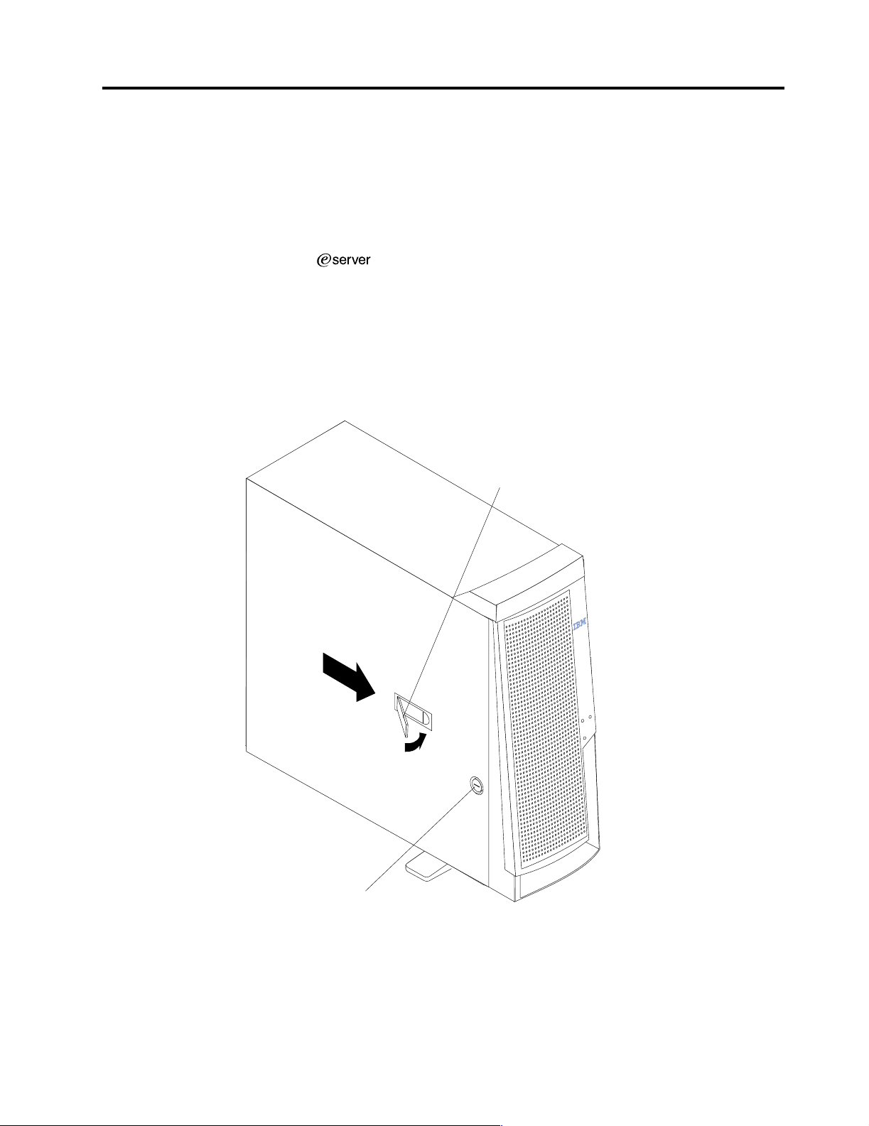
T urning off the server . . . . . . . . . . . . . . . . . . . . . . . . 9
Cover-release
latch
Key lock
© Copyright IBM Corp. 2000 3
Page 12

Features and specifications
This section pro vides a summary of the features and specificat ions of the xSeries 220
server.
Microprocessor:
• Intel® Pentium® III microprocessor with MMX™ technology and SIMD
extensions
• 256 KB* ECC, level-2 cache (min.)
• 133 M Hz front - s i de b u s ( F S B )
• Support f or up to two microprocessors
Memory:
• Standard: 128 MB
• Maximum: 4 GB*
• Type: 133 MHz, ECC, SDRAM, registered DIMMs
• Slots: 4 dual in-line
Drives standard:
• Diskette: 1.44 MB
• CD-ROM: 48X IDE
• Supports hot-swap SCSI hard disk drives (some models)
1
*
Expa nsion bays:
• T w o 5.25-in. bays (one CD-ROM drive installed)
• Two 3.5-in. bays (one diske t te drive installe d )
• Three 3.5-in. slim bays available in drive cage (some models have a hard disk
drive installed)
PCI expansion slots:
• Th ree 33 M Hz/6 4- b i t
• Two 33 MHz/32-bit
Power suppl y:
One 330 watt autosensing (115-230 V ac)
Video:
• S3 vide o con tro ll er (integra ted on syste m b oard)
• Compatible with SVGA and VGA
• 8 MB SDRAM video memory
Size
• Height: 470 mm (18.5 in.)
• Depth: 508 mm (20 in.)
• Wi dth: 165 mm (6.5 in.)
• Weight: approximately 19.5 Kg (43 lb.) when fully configured or 15.9 Kg (35 lb.)
minimum
Integrated functions:
• Ultra160 SCSI low voltage differential (LVD) controller
• One 10BASE-T/100BASE-TX Intel Ethernet controller on the system board
• Two serial ports
• Parallel port
• T wo Universal Serial Bus (USB) ports
1. KB equals approximat ely 1000 bytes. MB equals approximately 1000000 bytes. GB equals appro ximately 1000000000 bytes.
4 Hardware Maintenance Man ual: xSer ies 220
Page 13

• Keyboard port
• Mouse port
• IDE controller port
• Video port
Acoustical noise emissions:
• Sound power, idling: 5.9 bel maximum
• Sound power, operating: 6.1 bel maximum
Environment:
• Air temperature:
— Server on: 10º to 35º C (50.0º to 95.0º F). Altitude: 0 to 914 m (2998.7 ft)
— Server on: 10º to 32º C (50.0º to 89.6º F). Altitude: 914 m (2998.7 ft) to 2133 m
(6998.0 ft)
— Server off: 10º to 4 3º C (50.0º to 109. 4º F). M aximum alti tude : 2133 m (6998.0 f t)
• Humidity:
— Server on: 8% to 80%
— Server off: 8% to 80%
Heat output:
Approximate heat output in Britis h thermal u nits (Btu ) per hour
• Minimum configu r ation: 341 Btu (100 watt s)
• Maximum configurat i on : 1604 Btu (470 watts)
Server features
Electrical input:
• Sine-wave input (50-60 Hz) required
• Input voltage low ran ge:
— Minimum: 100 V ac
— Maximum: 127 V ac
• Input voltage high range:
— Minimum: 200 V ac
— Maximum: 240 V ac
• Input kilovolt-amperes (kVA), approximately:
— Minimum: 0.08 kVA
— Maximum: 0.52 kVA
The design of the server takes advantage of advancements in symmetric
multiprocessing (SMP), data storage, and memory management. The server
combines:
• Impressive performance using an innovative approach to SMP
The server supports up to two Pentium III microprocessors. The server comes
with one mic rop ro ces sor ins tall ed; y o u can i nst all an add ition al m icr o pr oc esso r to
enhance performance and provide SMP capability.
• Large sy stem memory
The me mo ry bus in th e se rver sup p or ts up to 4GB of sy s t e m memory. The
memory controller provides error correcting code (ECC) support for up to four
industry-standard PC133, 3.3 V, 168-pin, 8-byte, registered, synchronousdynamic-rando m a ccess memory ( SDRAM) dual inline memory modules
(DIMMs).
General information 5
Page 14

• System-management capabilities
System-management software is included with the server to manage the
function s of the server loca lly and remot e ly. Refer to the documentation th at
comes with the system-management software for more information.
• Integrated network environment support
The server comes with an Ethernet controller on the system board. This Ethernet
controller has an interface for connecting to 10-Mbps or 100-Mbps networks. The
server automatically selects between 10BASE-T and 100BASE-TX environments.
The controller provides full-duplex (FDX) capability, which allows simultaneous
transmission and recep tion of data on the Ethernet local area network ( LAN).
• IBM ServerGuide™ CDs
The ServerGuide CDs that are in cluded wit h th e ser ver provide programs to help
you set up the server and install the network operating system (NOS). The
ServerGuide program detects the hardware options that are installed, and
provides the correct configuration pr ograms and device drivers. In addition, the
ServerGuide CDs include a variety of application programs for the server.
Reliability, availability, and serviceability
Three of the most important considerations in server design are reliability , availability ,
and serviceability (RAS). The RAS fact or s hel p to ensure the integrity of the data that
is stored on the server, the availability of the server when it is needed; and the ease
with which problems can be diagnosed and repaired.
The following is an abbreviated list of the RAS features that e server supports:
• Automatic restart after a power failure
• Cyclic redundancy check (CRC) checking on the small computer system interfa ce
(SCSI) buses
• Diagnostic light-emitting diodes (LEDs)
• Error checking and corr ecting (ECC) memory
• Error codes and messages
• Menu-driven setup, system configuration, redundant array of independent disks
(RAID) configuration (optional), and diagnostic programs
• Optional system-management adapter subsystem to provide control for remote
system management
• Optional Wake on LAN
adapter)
• Power and temperature monitoring
• Power-on self-test (POST)
• Proce ssor serial number access
• System error logging (POST)
• Upgradeable basic input/output system (BIOS) and diagnostics
• Vital product data (VPD) on memo ry, syste m b oard, and hot-swap drive
backplane
®
(WOL) function through network-interfa ce card (NIC
Server controls and indicators
This section identifies the controls and indicators on the front of the server.
6 Hardware Maintenance Man ual: xSer ies 220
Page 15
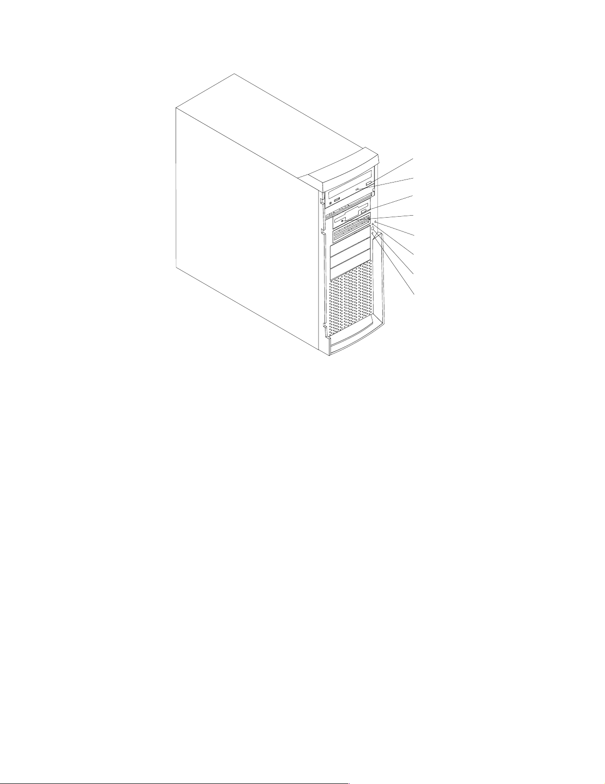
CD-ROM
eject button
CD-ROM drive
activity light
Diskette-eject
button
Diskette drive
activity light
SCSI
activity light
Power-on
light
Power-control
button
System error
light
CD-ROM eject button: Press this b u tton to release a CD f rom the drive.
CD-ROM drive activity light: When this light is on, it indicates that the CD-R O M
drive is in use.
Diskette-eject button: Press this button to release a diskette from the drive.
Diskette-drive activity light: When this light is on, it indicates that the diskette drive
is in use.
SCSI activity light: When this green light is flashing, the controller is accessing a
SCSI device, for example, a hard disk drive.
Note: Hot-swap hard disk drives also have an activity light. This light is also known
as the SCSI hard disk drive activity light.
If the server has a ServeRAID™ controller installed and this light flashes slowly (one
flash per second), the drive is being rebuilt. When the light flashes rapidly (three
flashes per second), the controller is ident ifying th e driv e.
Power-on light: When this green light is on, system power is present in the server.
Power-control button: Press this bu t ton to man ually tur n the se rver on or off.
System error light: When this amber light is on, it indicates that a system error has
occurred. An amber error light on the interior of the server, adjacent to the faulty
component, will also be on to further isolate the error. (For more information, see
“Diagnostics” on page 11.)
Cover-release latch: Slide this lever to release the cover.
General information 7
Page 16
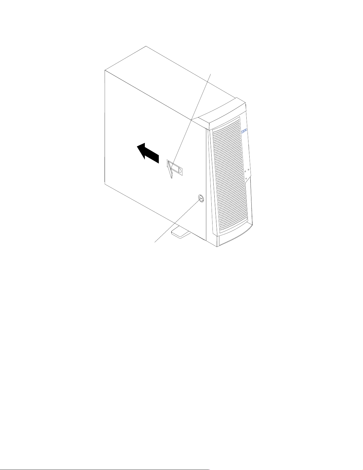
Cover-release
latch
Starting the server
After you plug the power cord of your server into the power supply and an electrical
outlet, the server can start in any of the following ways:
• You can press the power-control button on the front of the server to start the
server.
Notes:
1. You can install a circular disk over the power-control button to prevent
accidental manual power-off. This disk, known as the power-control bu tton
shield, comes with your server .
2. After you plug the power cord of your server into an electrical outlet, wait
approximately 20 seconds before pressing the power-control button. During
this time, the system is initializing; therefore, the power-control button does
not respond.
• If the server is turned on and a power failure occurs, the server will start
automatically when power is restored.
• The Wake on LAN feature will turn on the server at the set time (when a Magic
Packet is received), provided that all of the following conditions are met:
— AC power is present.
— The server i s e ither off or shu t down from an Advanced Configuration and
Power Interface (ACPI) operating system.
Key lock
8 Hardware Maintenance Man ual: xSer ies 220
Page 17

— The Wake on LAN featu re is enabled in the Configuration/Setup Utilit y
program.
— A supported Wake on LAN adapter is installed in PCI slot 1 and is connected
to the system board with the 3-pin auxiliary power connector.
Notes:
1. See “Choices available f r om the Conf igurati on/Setup main m enu” on page 30
for a description of the Config urat ion /Se tup Utilit y program .
2. See “System board option s connectors” on page 55 for connector locations.
3. For additional infor mation on the Wake on LAN function, adapters, and
cables, refer to the documentation that comes with the adapters.
4. See “Ethernet port” on page 93 for informati on on Ethernet controllers and
adapters, and Wake on LAN PCI adapters.
• If the optional system-mana gement adapter is installed in your server, the
system-management adapter can turn on the server.
CAUTION:
The power control butto n on the device and the power switch on the powe r supply do not
turn off the el ectr ica l curr ent suppl ied to t he dev ice. The devi ce also might have mor e than
one power cord. To remove all electri cal current from the device, ensure that all power
cords are disconnected from the power source.
Turning off the server
You can turn off the server in any of the following ways:
• You can press the power-control button on the top of the server. This starts an
orderly shutdown of the operating system, if this feature is supported by your
operating sy stem.
Note: After tu rning off the se rver, wait at least five seconds before you press the
powe r-c ontrol butto n to tu r n on the server ag a in .
• You might need to press and hold the power-control button for more than four
seconds to cause an immediate shutdown of the server and to force the power off.
You can use this feature if the operating system stops functioning.
• You can disconnect the server power cords from the electrical outlets to shut off
all power to the server.
Note: After di sconnecting the power cords, wait appr oximately 15 seconds for
your system to stop running. Watch for the p owe r-on light to stop
blinking.
General information 9
Page 18

10 Hardware Maintenance Manual: xSeries 220
Page 19

Diagnostics
Diagnostic tools overview . . . . . . . . . . . . . . . . . . . . 11
POST . . . . . . . . . . . . . . . . . . . . . . . . . . . . . . . . . . . . . . 11
POST beep codes. . . . . . . . . . . . . . . . . . . . . . . . . . . . 12
POST error messages . . . . . . . . . . . . . . . . . . . . . . . . 12
POST error log . . . . . . . . . . . . . . . . . . . . . . . . . . . . . . 12
Small computer system interface messages . . . . . 12
Diagnostic programs and error messages . . . . . . . 13
Text messages. . . . . . . . . . . . . . . . . . . . . . . . . . . . . . . 14
Starting the diagnostic programs . . . . . . . . . . . . . . 14
Viewing the test log. . . . . . . . . . . . . . . . . . . . . . . . . . 15
Diagnostic error messages . . . . . . . . . . . . . . . . . . . . 15
This section provides basic troubleshooting information to help you resolve some
common pr oblems that might occur wi th the server.
If you cannot locate and correct the problem using the information in this sec tion,
refer to “Symptom-to-F RU index” on page 111 for more information.
Diagnostic tools overview
The following tools are available to help you identify and resolve hardware-related
problems:
• POST beep cod es , error me ss ages , and error l ogs
The power-on self-test (POST) generates beep codes and messages to indicate
successful test completion or the det e ction of a problem. See “POST” for more
information.
• Diagnostic programs and error messages
The server diagnostic programs are stored in upgradable read-only memory
(ROM) on the system board. These programs are the primary method of testing
the major components of the server. See “Diagnostic programs and error
messages” on page 13 for more informa ti on .
• Error symptoms
These charts list problem symptoms, along with suggested steps to correct the
problems. See “Diagnosing errors” on page 21 for more information.
• Diagnostic LEDs
The serve r has light-emi tting diodes (LE Ds) to help you iden tify problems with
server components. These LEDs are part of the diagnostics that are built into the
server. See “Diagnostic LEDs” on page 18 for more information.
Power checkout . . . . . . . . . . . . . . . . . . . . . . . . . . . . 16
Recovering BIOS. . . . . . . . . . . . . . . . . . . . . . . . . . . . 16
Identifying problems using status LEDs. . . . . . . . 17
Front panel and system board LEDs . . . . . . . . . . . 18
Diagnostic LEDs . . . . . . . . . . . . . . . . . . . . . . . . . . . . 18
Replacing the battery. . . . . . . . . . . . . . . . . . . . . . . . 19
T e mperature checkout . . . . . . . . . . . . . . . . . . . . . . . 20
Diagnosing errors. . . . . . . . . . . . . . . . . . . . . . . . . . . 21
T roubleshooting the Ethernet controller . . . . . . . . 21
Ethernet controller messages . . . . . . . . . . . . . . . . . 23
POST
When you turn on the server, it performs a series of tests to check the operation of
server components an d some of the options installed in th e se rver. This se ries of tests
is called the power-on self-test or POST.
If POST finishes without detecting any problems, a single beep sounds and the first
screen of the operating system or application program appears.
© Copyright IBM Corp. 2000 11
Page 20

If POST detects a problem, more than one beep sounds and an error message appears
on the screen. See “POST beep codes” and “POST error messages” for more
information.
Notes:
1. If you have a power-on password set, you must type the password and press
Enter, when prompted, before POST will continue.
2. A single problem might cause several error messages. When this occurs, work to
correct the cause of the fir st e rror message. After you correct the cause of the first
error message, the other error messages usually will not occur the next time you
run the te s t .
POST beep codes
POST generates beep codes to indicate successful completion or the detection of a
problem.
• One beep indicates the successful completion of POST.
• More than one beep indicates that POST detected a problem. For more
information, see “Beep symptoms” on page 111.
POST error messages
POST error messages occur during startup when POST finds a problem with the
hardware or detects a change in the hardware configuration. For a list of POST
errors, se e “ P O S T error codes” on page 119.
POST error log
The POST error log contains the three most recent error codes and messages that the
syste m gener a te d du ring PO ST.
To view the contents of the error logs, start the Configuration/Setup Utility program
(see “Starting the Configuration/Setup Utilit y program” on page 30); then, sele ct
Error Logs from the main menu.
Small computer system interface messages
The following table lists actions to take if you receive a SCSI error message.
Note: If your server does not have a hard disk drive, ignore any message that
indicates that the BIOS is not installed.
You will get these messages only when running the SCSISelect Utility.
12 Hardware Maintenance Manual: xSeries 220
Page 21

SCSI Messages Description
All One or more of the following might be causing the problem.
• A failing SCSI device (adapter, drive, controller)
• An improper SCSI configuration
• Duplicate SCSI IDs in the same SCSI chain
• A n improperly installed SCSI terminator
• A defective SCSI terminator
• A n improperly installed cable
• A defectiv e cable
Action:
Verify that :
• The external SC SI devic es are turned on. Externa l SCSI de vices m ust
be turned on before the server.
• The cables for all external SCSI devices are connected correctly.
• The last device in each SCSI chain is termin ated prope r l y.
• The SCSI devices are co nfigured co r rectly.
If the above items are correct, run the diagnostic programs to obtain
additional information about the failing device. If the error remains or
recurs, call for service.
Table 1. SCSI messages.
Diagnostic programs and error messages
The server diagnostic prog rams are stored in upgradable read-only memory (ROM)
on the system board. These programs are the primary method of testing the major
components of the server.
Diagnostic error messages indicate that a problem exists ; they ar e not necess aril y
intended to be used to identify a failing part. Troubleshooting and servicing of
complex problems that are indicated by error messages should be performed by
trained service personnel.
Somet i m e s th e f i rs t e rro r to occur caus e s add i tional erro rs . In this case , the se r v er
displays more than one error message. Always follow the suggested action
instructions for the first error message that appears.
The following sections contain the error codes that might appear in the detailed test
log and summary log when running the diagnostic programs.
The error code format is as follows:
fff-ttt-iii-date-cc-text message
where:
fff is the thre e -digit fun ction code that in di cates the function being
tested when the error occurred. For example, function c od e 089 is for
the microprocessor.
ttt is the thre e -digit failure code that indicates the exact test failu re that
was encou ntered.
Diagnostics 13
Page 22

iii is the thr e e-digit device ID.
date is the date that the diagnostic test was run and the error recorded.
cc is the check digit that is used to verify the validity of the information.
text message is the diagnostic message that indicates the rea son for the problem .
Text messages
The diagnostic text message format is as follows:
Function Name: Result (test specific string)
where:
Func tion Name is the name of the function being tested when the err or occurre d. This
corresponds to the function code (fff) given in the previous list.
Result can be one of the following:
Passed This result occurs when the diagnostic test com p letes
without any errors.
Failed This re sult occurs when the di agnostic te st discovers an error.
User Aborted
This r e su lt occurs when y ou s top the diagnosti c test before it
is complete.
Not Applicable
This result occurs when you specify a diagnostic test for a
device that is not present.
Aborted This result occurs when the test could not proceed because
of the syste m configurati on.
Warning This result occurs when a possible problem is rep orted
during the diagnostic test, such as when a device that is to be
tested is not installed.
Te st Spec i fi c Stri ng
This is additional information th at you can use to anal yz e the
problem.
Starting the diagnostic programs
You can press F1 while running the diagnostic programs to obtain Help information.
You also can press F1 from within a help screen to obtain online documentation f rom
which you can select different categories. To exit Help and return to where you left
off, press Esc.
To start th e di agnostic pr ograms:
1. Turn on the server and watch the screen.
2. When the message F2 for Diagnostics appears, press F2.
3. Type in the appropriate password; then, press Enter .
4. Select either Extended or Basic from the top of the screen.
5. When the Diagnostic Programs screen appears, select the test you want to run
from the list that appears; then, follow the instructi ons on the screen.
14 Hardware Maintenance Manual: xSeries 220
Page 23

Notes:
a. If the server stops during testing and you cannot continue, restart the server
and try running the diagnostic programs again.
b. The keyboard and mouse (pointing device) tests assume that a keyboard and
mouse are attached to the server.
c. If you run the diagnostic programs with no mouse a tta ched to the server, you
will not be able to navigate between test categories using the Next Cat and
Prev Cat buttons. All other functions pro vided by mouse-sel e ctable buttons
are also available using the function keys.
d. You can run the USB interface test and the USB external loopback test only if
there are no USB devices attached.
e. You can view server configuration information (such as system configuration,
memory contents, interrupt request (IRQ) use, direct memory access (DMA)
use, device drivers, and so on) by selecting Hardware Info from the top of the
screen.
When the tests have completed, you can view the Test Log by selectin g Utility from
the top of the screen.
If the hardware checks out OK but the problem persists during normal server
operations, a software error might be the cause. If you suspect a software problem,
refer to the information that comes with the software package.
Viewing the test log
The test log will not contain any information until after the diagnostic program has
run.
Note: If you already are running the diagnostic programs, begin with step 3..
To view the test log:
1. Turn on the server and watch the screen.
If the server is on, shut down the operating system and restart the server.
2. When the message F2 for Diagnostics appears, press F2.
If a power-on password is set, the server prompts you for it. Type in the
appropriate password; then, press Enter.
3. When the Diagnostic Programs screen appears, select Utility from the top of the
screen.
4. Select View Test Log from the list that appears; then, follow the instructions on
the screen.
The system maintains the test-log data while the server is powered on. When you
turn off the power to the server, the test log is cleared.
Diagnostic error messages
For descriptions of the error messages that might appear when you run the diagnostic
programs, see “Diagnostic error codes” on page 115. If diagno stic error me ssages
appear that are not listed in those tables, make sure that the server has the latest levels
of BIOS, ServeRAID, and diagnostics microcode installed.
Diagnostics 15
Page 24

Power checkout
Power problems can b e difficu lt to trou bleshoot. For instance, a short circui t can exist
anywhere on any of the power distribution bu sses. Usually a short circuit will cause
the power su b s ystem to shut d own because of an overcurrent conditi o n.
A general procedure for troubleshooting power problems is as follows:
1. Power off the system and disc onnect the AC cord(s).
2. Check for loose cables in the power subsystem. Also check for short circuits, for
3. Remove adapters and disconnec t th e cables and power connectors to all intern al
4. Reconnect the AC cord and power on the system. If the system powers up
To use this method it is important to know the minimum configuration required for a
system to power up (see page 125).
Recovering BIOS
instance if there is a loose screw causing a short circuit on a circuit board.
and external devices until system is at minimum configuration required for
power on (see "Minimum operating requirements" on page 125).
successfully, replace adapters and devices one at a time until the problem is
isolated. If system does not power up from minimal configuration, replace FRUs
of minimal configuration one at a time until the problem is isolated.
If the BIOS has become damaged, such a s from a power failure during a flash updat e,
you can recover the BIOS using the flas h ROM page-swa p jumper (J38) and a BIOS
flash diskette.
Note: You can obtain a BIOS flash diskette fr om one of the following sources:
• Use the ServerGuide program to make a BIOS flash diskette.
• Download a BI OS f lash diskette from the World Wide Web. Go to
http://www.ibm.com/pc/support/, select IBM Server Support, and
make the selections f o r your serve r.
The flash memory of your server consists of a primary page and a backup page. The
J38 jumper controls which page is used to start the server. If the BIOS in the primary
page is damaged, you can use the backup page to star t the server; then, start the BIOS
flash diskette to restore the BIOS to the primary page.
To rec ove r th e BIOS, do the f oll ow ing :
1. Turn off the server and peripheral devices and disconnect all external cables and
power cords; then, remove the cover.
2. Locate jumper J38 on the system board .
16 Hardware Maintenance Manual: xSeries 220
Page 25
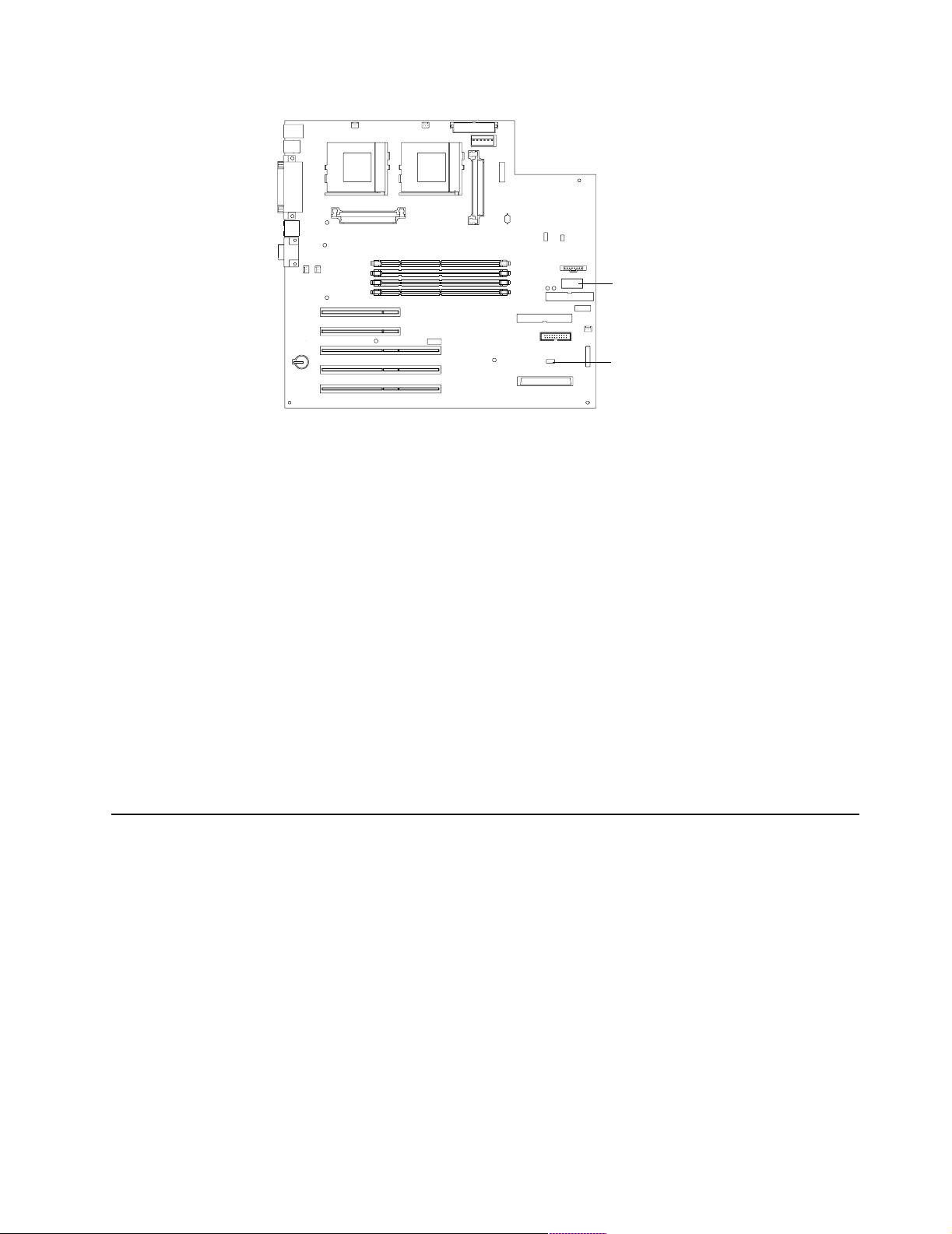
Switch block
Flash ROM
page-swap
jumper (J38)
3. Move J38 to the lo setting (pins 1 and 2) to enable BIOS recovery mode.
4. Reconnect all external cables and power cor ds and turn on the peripher al devices.
5. Insert the BIOS flash diskette in the diskette drive.
6. Restart the server. The system begins the power-on self-test (POST).
7. Select 1 - Update POST/BIOS from the menu th at contains vario u s fl ash (update)
options.
8. When prompted as to whether you want to save the current code to a diskette,
press N.
9. When prompt e d to choose a language , se lect a language (from 0 to 7) and pre ss
Enter to accept your choice.
10. Do not restart your system at thi s time.
1 1. Remove the BIOS flash diskette from the diskette drive.
12. Turn off the server.
13. Move jumper J38 to the hi setting (pins 2 and 3) to return to no rmal startup mode.
14. Restart the server.
Identifying problems using status LEDs
The serve r has diagnostic LEDs to help you identi f y problems with some server
components. Use the diagno stic LEDs to identify the f ailing or inco rrectly installe d
components.
Diagnostics 17
Page 26

Front panel and system board LEDs
The server do e s not contain a diagnostic or informat ion panel. The system error LED
is on the front panel inside the server . All of the remaining error LEDs are on the
system board, adjacent to the failing components. See “Diagnostic LEDs” for
information on ident ifying p roblems using the se LED s.
The meanings of these LEDs are as follows:
CPU1 Microproce ssor number 1 (co nn e ctor U12) fault
CPU2 Microprocessor number 2 (co nne ctor U11) fault
Fan 1 Fan number 1 (connector J10) failure (see note 1)
Fan 2 Fan number 2 (connector J18) failure (see note 1)
MEM1 DIMM number 1 (connector J19) fault
MEM 2 DIMM number 2 (connector J21) fault
MEM 3 DIMM number 3 (connector J23) fault
MEM 4 DIMM number 4 (connector J26) fault
VRM1 Microprocessor VRM number 1 (connector J42) fault (see note 1)
VRM2 Microprocessor VRM number 2 (connector J12) fault (see note 1)
Notes:
1. The fan and VRM LEDs will illuminate only if the optional system management
adapter is installed in the server.
2. The server does not support user-replaceable power supplies or fans.
Diagnostic LEDs
You can use the diagnostic LEDs built into the server to quickly identify the type of
system error that occurred. The server is designed so that LEDs remain illuminated
when the server shuts down, as long as the power supply is operating properly. This
feature helps you to isolate the problem if an err or causes the server to shut down. To
correct specific problems, see “Symptom-to-FRU index” on page 111.
System Error LED (on the front panel) System board LED Cause
On
A system error was detected. Check to
see which of the LEDs on the system
board ar e o n .
On MEM1, MEM2 , MEM3, or MEM4
On CPU1 or CPU2 (system board) One of the microprocess ors ha s failed,
On Fan 1 or Fan 2 One of the fans has failed or is
On VRM1 or VRM2 (system board) One of the microprocessor VRMs has
None The system error log is 75% or more
full or a Predictive Failure Analysis
(PFA) alert was logged.
A memory error occurred.
(system board)
or a microprocessor is installed
incorrectly.
operating too slowly .
failed, or a microprocessor VRM is
installed in the wrong connector.
Table 2. Diagnostic LEDs.
18 Hardware Maintenance Manual: xSeries 220
Page 27
System Error LED (on the front panel) System board LED Cause
On System error (front panel) The diagnostic LEDs have detected a
system error.
Off None The diagnostic LEDs have not
detected a system error.
Table 2. Diagnostic LEDs.
Replacing the battery
When replacing the battery you must replace it with a lithium battery of the same
type, from the same manufacture r. To avoid possible danger r e ad and follow the
safety statement below.
To order repl acement batteries, call 1-800 -772-2227 within the United States, and
1-800-465-7999 or 1-800-465-6666 within Canada. Outside the U.S. and Canada, call
your IBM reseller or IBM marketing representative.
Note: After you replace the battery, you must reconfigure the server and reset the
system date a nd time.
CAUTION:
When replacing the battery, use only IBM Part Number 33F8354 or an equivalent
type battery recommended by the manufacturer. If your system has a module
containing a lithium battery, replace it only with the same module type made by
the same manufacturer. The battery contains lithium and can explode if not
properly used, handled, or disposed of.
Do not:
• Throw or immerse into water
• Heat to more than 100°C (212° F)
• Repair or disassemble
Dispose of the battery as required by local ordinances or regulations.
Do the following to replace the battery:
1. Read “Before you begin” on page 58, and follow any special ha ndl ing and
installation instructions supplied with the replacement battery.
2. Turn off the server and peripheral devices and disconnect all external cables and
power cords; then, remove the server cover.
3. Remove any PCI cards that might impede access to th e b a ttery.
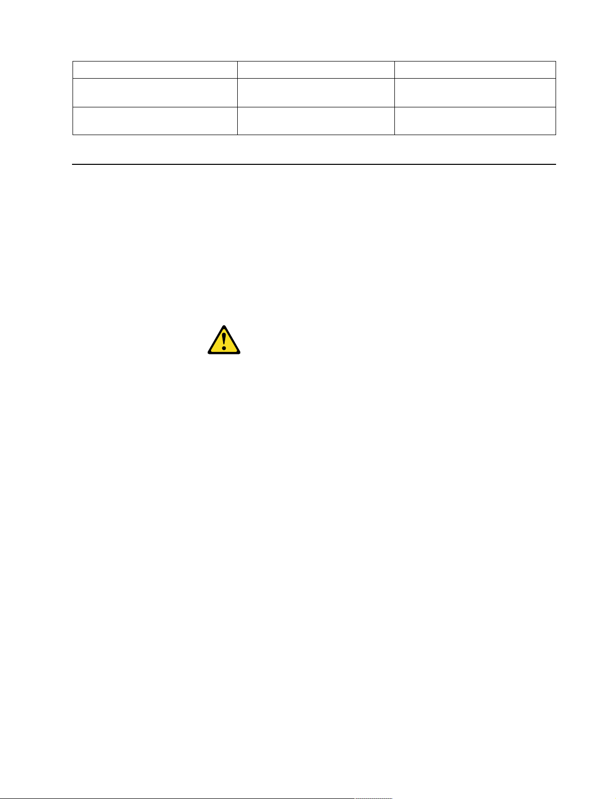
4. Remove the battery:
a. Use one finger to lift the battery clip over the battery.
b. Use one finger to slightly slide the battery out from its socket. The spring
mechanism will push the battery out toward you as you slide it from the
socket.
c. Use your thumb and index finger to pull the battery from under the battery
clip.
Diagnostics 19
Page 28
d. Ensure that the battery clip is touching the base of the battery socket by
pressing gently on the clip.
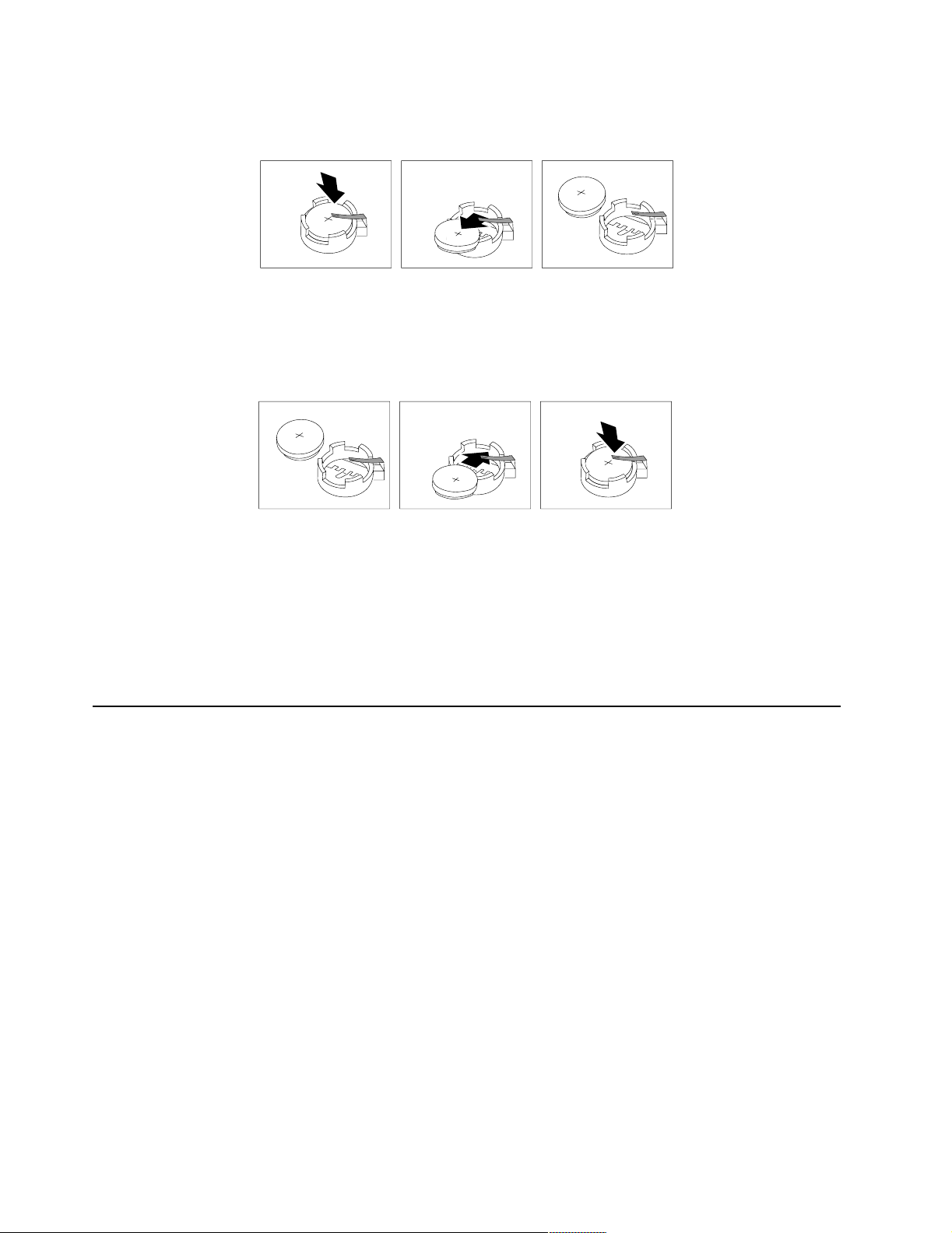
5. Insert the new battery:
a. Tilt the batt e ry so that you can insert it into the so cket, under the b a ttery clip.
b. As you slide it under the battery clip, press the battery down into the socket.
6. Reinstall the server cover and connect the cables.
7. Turn on the ser ver.
8. Start the Configuration/Setup Utility program and set configuration parameters.
• Set the system date and time.
• Set the power-on password.
• Reconfigure your server.
Temperat ur e checkou t
Proper cooling of the system is important for proper operation and system reliability.
For a typical IBM xS e r i e s se r v er, you sh ould make su re :
• Each of the drive bays has either a drive or a filler panel installed
• The cover is in place during normal operation
• There is at least 50 mm (2 inches) of ventilated space at th e sides of the server and
100 mm (4 inches) at the rear of the server
• The cover is removed for no longer than 30 minutes while the server is operating
• A removed hot-swap drive is replaced within two minutes of removal
• Cables for optional adapters are routed according to the instructions provided
with the adapters (ensure that cables are not restricting air flow)
• The fans are operati ng correctly and the air flow is good
• A failed fan is replaced within 48 hours
In addition, ensure that the environmental specifications for the system are met. See
“Features and specifications” on page 4.
20 Hardware Maintenance Manual: xSeries 220
Page 29

Diagnosing errors
To find solutions to problems that have definite symptoms, see “Error symptoms” on
page 117.
If you cannot find the problem there, go to “Starting the diagnostic programs” on
page 14 to test the se rver.
If you ha ve jus t ad de d new soft ware or a n ew opt ion and the se rver i s not wo rkin g, d o
the following before using the error symptoms table:
• Remove the software or device that you just added.
• Run the diagnostic tests to determ ine if the server is runn ing correctly.
• Reinstall the new software or new device.
Troubleshooting the Ethernet controller
This section provides troubleshooting information for problems that might occur with
the 10/100 Mbps Ethernet controller.
Network connection problems
If the Ethernet controller ca nnot connec t to the network, check the following:
• Make sure that the cable is installed correctly.
• Determine if the hub supports auto-negotiation. If not, try configuring the
• Check th e LAN a ctivity light on the front of the server. The LAN activity li ght
• Make sure that you are using the correct device drivers, supplied with your
• Check for operating system-specific causes for the problem.
• Make sure that the device drivers on the client and server are using the same
• Test the Ethernet controller.
The network cable must be securely attached at all connections. If the cable is
attached but the problem persists, try a different cable.
If you set the Ethernet contr oll er to operate at 100 Mbps, you must use Cate gory 5
cabling.
If you directly connect two workstations (without a hub), or if you are not using a
hub with X ports, use a crossover cable.
Note: To determine whet her a hub has an X port, check the port label. If the label
contains an X, the hub has an X port.
integrated Ethernet controller manually to match the speed and duplex mode of
the hub.
illuminates whe n the Et hernet controller s ends or receive s data over th e Ether ne t
network. If the LAN activity light is off, make sure that the hub and network are
operating and that the correct device drivers are loaded.
server.
protocol.
How you test the Ethernet controll er depends on which operating system you are
using (see the Ethernet controller device driver README file).
Ethernet controller troubleshooting chart
You can use the following troubleshooting chart to fi nd sol u ti ons to 10/100 Mbps
Ethernet controller problems that have definite symptoms.
Diagnostics 21
Page 30

Ethernet controller
problem
The server stops
running when loading
device drivers.
The LAN activity light
does not light.
Suggested Action
The PCI BIOS interrupt settings are incorrect.
Check the following:
• Determine if the interrupt (IRQ) setting assigned to the Ethernet
controller is also assigned to another device in the
Configuration/Setup Utility program.
Although interrupt sharing is allowed for PCI devices, some
devices do not functi on well wh en the y share an interr up t with
a dissimilar PCI device. Try changing the IRQ assigned to the
Ethernet controller or the other device. For exa mple, for
NetWare V ers i ons 3 and 4 it is recommended that di sk
controllers not share interrupts with LAN controllers.
• Make sure that you ar e using the most r ecent device driver
available from the World Wide Web.
• Run the netwo rk diag n osti c progra m .
If the problem remains, call for service.
Check the following:
• Make sure that you have loaded the network device drivers.
• The network might be idle. Try sending data from this
workstation.
• Run diagnostics on the LEDs.
• The function of this LED can be changed by dev i ce driver load
parameters. If necessary, remove any LED parameter settings
when you load the device drivers.
Data is incorrect or
sporadic.
The Ethernet
controller stopped
working when
another adapter was
added to the server.
Check the following:
• Make sure that you are using Category 5 cabling when
operating the server at 100 Mbps.
• Make sure that the cables do not run close to noise-indu cing
sources like fluorescent lights.
Check the following:
• Make sure that the cable is connected to the Ethern et controller.
• Make sure that your PCI system BIOS is curr ent .
• Reseat the adapter.
• Determine if the interrupt (IRQ) setting assigned to the Ethernet
adapter is also assigned to another device in the
Configuration/Setup Utility program.
Although interrupt sharing is allowed for PCI devices, some
devices do not functi on well wh en the y share an interr up t with
a dissimilar PCI device. Try changing the IRQ assigned to the
Ethernet adapter or the other device.
If the problem remains, call for service.
Table 3. Ethernet troubleshooting cha rt.
22 Hardware Maintenance Manual: xSeries 220
Page 31

Ethernet controller
problem
The Ethernet
controller stopped
working w ith ou t
apparent cause.
Check the following:
• Run diagnost ics for t he Eth ernet controller.
• Try a different connector on the hub.
• Reinstall the device drivers. Refer to your operating-system
documentation and to the ServerGuide information.
If the problem remains, call for service.
Table 3. Ethernet troubleshooting cha rt.
Ethernet controller messages
The integrated Ethernet controller might display messages from the following device
drivers:
• Novell™ NetWare™ or IntraNetWare Server ODI
• NDIS Adapter for level 4.0 (Windows NT)
Novell NetWare or IntraNetWare server ODI
driver teaming messages
This section provides explanations of the error messages for the Novell NetWare or
IntraNetWare server ODI driver, and suggested actions to resolve each problem.
Suggested Action
Message Description
Couldn’t allocate resources Explanation: An unknown error has occurred when trying to
allocate needed resources for the AFT Module.
Action:
• Check the server configuration. If the problem pers ist s,
contact your net work supplier.
• Verify that th e Ethernet controller is enabled. If the
Ethernet controller is enabled , ru n the diagnost ic
programs.
AFT group for prima r y
adapter in slot nnn al ready
exists.
Error locating DCT addresses
in internal table. Make sure
that you have loaded LAN
drivers after loading
AFT.NLM.
Insufficient number of
arguments specified.
Explanation: An attempt was made to rebind an adapter
already in an AFT group.
Action: Check the AFT slot numbers for existing AFT teams.
If the problem per s is ts, co nt ac t your network supplier.
Explanation: The bind command was entered prior to
loading the device driver. The device driver must be loaded
after loading AFT.NLM but before any bind command can be
issued.
Action: Load the driver for the supported adapter and try
loading the AFT module again. If the problem persists,
contact your net work supplier.
Explanation: The appropriate or expected number of
parameters was not enter ed in a command.
Action: Check the parameters required for the given
command. If the problem persists, contact your network
supplier.
Table 4. NetWare driver messages for the Ethernet controller.
Diagnostics 23
Page 32

Message Description
Duplicate slot numbers
detected.
’Xxx’ is not sup ported fo r
AFT team.
Primary and Secondary
adapters do not match. AFT
group is not created.
Requested number of
Secondary cards are not
found.
Failed to create AFT group.
Make sure that the drive rs
for suppor t e d ad apters are
loaded, primary ada pte r i s
bound to protocols, and
secondary adapter is not
bound t o a ny protocols.
Explanation: An attempt has been made to bind the same
slot number more than once.
Action: Check the slot numbers entered during the bind.
Adapter slot numbers must be valid and unique. If the
problem persists, contact your network supplier.
Explanation: A bind command has been issued for adapters
not supported by AFT.NLM.
Action: Make sure that you attempt to bind only adapters
supported by AFT.NLM.
Explanation: A bind command was entered for an adapter
team that is a combina tion of server and clie nt adapters. An
AF T tea m must be a group i ng of the same classification of
adapter.
Action: V e rify that all the adap ters bound in a team are of the
same classification.
Explanation: The number of adapters specified in the bind
command could not be located.
Action: Verify the numbers and slot locations of the adapters
to be bound. If the problem persists, contact your network
supplier.
Explanation: Binding of protocol failed. Protocol is either not
bound to any adapter or is bound to more than one adapter in
the group.
Action: Ens u re that t he prot oc ol i s bou nd to on l y ad ap ter in
an AFT team.
Erro r i dentifying s lot
numbers for the specified
board names.
Can’t unbind specifie d slot
from AFT group. Make sure
that the slot you specified is
for the primary adapt e r in an
AFT group.
LAN adapter at slot nnnn
(Port 0xaa) failed to reset.
Check the state of the
adapter.
AFT is not supported on this
version of NetWare™.
Explanation: The mapping between the board name ent ered
and the slot number for an adapter could not be established.
Action: Check the board name for the adapter before issuing
the bind command. If the problem persists , co ntact your
network supplier.
Explanation: The number entered in the unbind command
was not the primary adap ter in an AFT group.
Action: Reissue the unbind command and specify the slot
number for the primary adapter.
Explanation: The adapter that you specified could not be
initialized.
Action:
1. Load the driver for the supported adapter.
2. Check that the adapter is seated properly in the slot and
try loading the AF T module again.
If the problem per s is ts, co nt ac t your network supplier.
Explanation: The NetWa re on your server is not a version
supported by AFT.
Action: Load and bind AFT only on supported versions of
NetWare (currently versi on 4.11 and above).
Table 4. NetWare driver messages for the Ethernet controller.
24 Hardware Maintenance Manual: xSeries 220
Page 33

Message Description
Failed to allocate resources
tags.
Please unload all LAN
drivers before unloading
AFT.NLM.
Explanation: An unknown error ha s occ urred when trying
to allocate needed resources for the AFT module.
Action: Check Server Configuration. If the problem persists,
contact your net work supplier.
Explanation: An attempt was made to unload the AFT.NLM
module before unloading the adapter driver.
Action: Unload the adapter driver before unloading the AFT
module.
Table 4. NetWare driver messages for the Ethernet controller.
NDIS 4.0 (Windows NT) driver messages
This section contains t he erro r messages for the NDIS 4.0 driv ers. The explan ation and
recommended action are included with each message.
Error code
(hex)
0x00 Explanation: The driver could not register the specified interrupt.
Action: Using the Configuration/Setup Utility, make sure that a PCI
interrupt is assigned to your Ethernet card, and that Ethernet is enabled.
0x01 Explanation: One of the PCI cards did not get the required resources.
Action: Using the Configuration/Setup Utility, make sure that a PCI
interrupt is assigned to your Ethernet card, and that Ethernet is enabled.
Description
0x02 Explanation: Bad node address (multicast address).
Action: Make sure the locally administered address is valid, if one is
specified. The address can not be a multicast address.
0x03 Explanation: Failed self-test.
Action: Make sure a cable is attached to the Ethernet connector. If the
problem persists, call for service.
0x0D Explanation: Could not allocate enough memory for transmit queues.
Action:
1. From the W indows NT deskt op, select Start -> Control Panel ->
Networks -> Adapters.
2. Select your IBM Ethernet adapter from the list.
3. Select Properties -> Advanced.
4. Lower the resource values that apply to the transmit queue.
0x0E Explanation: Could not allocate enough memory for receive queue.
Action:
1. From the W indows NT deskt op, select Start -> Contr o l P an e l ->
Network s -> Adapte rs.
2. Select your IBM Ethernet adapter from the list.
3. Select Properties -> Advanced.
4. Lower the resource values that apply to the receive queue.
Table 5. NDIS (Windows NT or Windows 2000) driver messages for the Ethernet
controller.
Diagnostics 25
Page 34

Error code
(hex)
0x0F Explanation: Could not allo cate enough memory for other structures.
Action:
1. From the W indows NT deskt op, select Start -> Control Panel ->
Networks -> Adapters.
2. Select your IBM Ethernet adapter from the list.
3. Select Properties -> Advanced.
4. Lower the value for the resource named in the message.
0x10 Explanation: Did not find any Ethernet controllers.
Action: Using the Configuration/Setup Utility, make sure that Ethernet is
enabled.
0x11 Explanation: Multiple Ethernet controllers found, but none matched the
required ID.
Action: Using the Configuration/Setup Utility, make sure that Ethernet is
enabled.
0x13 Explanation: Did not find any Ethernet controllers tha t matched the required
subven/subdev.
Action: Using the Configuration/Setup Utility, make sure that Ethernet is
enabled.
0x16 Explanation: Single adapter found but multiple instances tried to load.
Action: Using the Configuration/Setup Utility, make sure that Ethernet is
enabled, and that the slot containing t he IBM 10/100 Ethernet Adapter or the
IBM 10/100 EtherJ e t™ PCI adapter is enabled.
Description
0x17 Explanation: Slot parameter not specified in the registry.
Action: Remove the adapter driver and reinstall it. If the problem persists,
cal l for service.
All other 4character
hexadecimal
codes
Action: Call for service.
Table 5. NDIS (Windows NT or Windows 2000) driver messages for the Ethernet
controller.
Ethernet teaming messages:
Event ID Type Description
01 Error Explanation: Team N ame and physical adapter name are
the same. This is an invalid configuration.
Action: Reconfigure the adapter team by double-clicking
the PROSet icon in the control panel.
02 Error Explanation: Unable to allocate required resources.
Action: Free some memory resour ces and restart.
03 Error Explanation: Unable to read required registry parameters.
Action: Reconfigure the adapter team by double-clicking
the PROSet icon in the control panel.
Table 6. NDIS (Windows NT or Windows 2000) driver teaming messages for the
Ethernet controller.
26 Hardware Maintenance Manual: xSeries 220
Page 35

Event ID Type Description
04 Error Explanation: Unable to bind to physical adapter.
Action: Reconfigure the adapter team by double-clicking
the PROSet icon in the control panel.
05 Error Explanation: Unable to initialize an adapter team.
Action: Reconfigure the adapter team by double-clicking
the PROSet icon in the control panel.
06 Informational Explanation: Team nn. Primary adapter is initialized.
Action: None.
07 Informational Explanation: Team nn. Secondary adapter is initialized.
Action: None.
08 Informational Explanation: Team nn. Virtual adapter or Team is
initialized.
Action: None.
09 Informational Explanation: Team nn. Primary adapter is sw i tching over.
Action: None.
10 Warning Explanation: Team nn. Adapter link down.
Action: Make sure the adapter is functioning properly.
11 Informational Explanation: Team nn. Secondary adapter took over.
Action: None.
12 Warning Explanation: Team nn. Secondary adapter is deactivated
from the Team.
Action: Make sure the secondary adapter is functionin g
properly and that the adapter cable is securely connected
to the LAN.
13 Informational Explanation: Team nn. Secondary adapter has rejoined
the Team.
Action: None.
14 Informational Explanation: Team nn. Secondary adapter link is up.
Action: None.
15 Error Explanation: Team nn. The last adapter has lost its link.
Network connectio n has be en lost.
Action: Shut down the server and replace the adapters;
then, restart the server to reestablish the connection.
16 Informational Explanation: Team nn. An adapter has re-established the
link. Network conne ction has been restored.
Action: None.
17 Informational Explanation: Team nn. Preferred primary adapter has
been detected.
Action: None.
18 Informational Explanation: Team nn. Preferred secondary adapter has
been detected.
Action: None.
19 Informational Explanation: Team nn. Preferred primary adapter took
over.
Action: None.
20 Informational Explanation: Team nn. Preferred second ary adapter took
over.
Action: None.
Table 6. NDIS (Windows NT or Windows 2000) driver teaming messages for the
Ethernet controller.
Diagnostics 27
Page 36

Event ID Type Description
21 Warning Explanation: Team nn. Primary adapter do e s not se nse
any Probes. Possible reason: partitioned Team.
Action: Make sure the cables of the adapter team are
connected to the same LAN segment. Reconfigure the
team if necessary.
Table 6. NDIS (Windows NT or Windows 2000) driver teaming messages for the
Ethernet controller.
28 Hardware Maintenance Manual: xSeries 220
Page 37

Configuring the server
Using the Configurat ion /Se tup Utilit y program . 29
Starting the Configuration/Setup Utility program .
30
Choices available f rom the Configu r ation/S et up
main menu . . . . . . . . . . . . . . . . . . . . . . . . . . . . . . . . . 30
Using passwords . . . . . . . . . . . . . . . . . . . . . . . . . . . . 33
Using the SCSIS e le c t u til i ty p rog r a m . . . . . . . . . . . 35
The following configuration programs ar e pro vided with the server:
• Configuration/Setup Utility
This program is part of the basic input/output system (BIOS) that comes w ith the
server . You can use this program to configure seri al and parallel port assignments,
change interrupt request (IR Q) settings, change the driv e startup sequence, set the
date and time, and set passwords. See “Using the Configuration/Setup Utility
program” for more information.
• SCSISelect Utility
With the built-in SCSISelect Utility program, you can configure the devices
attached to the integrated SCSI controller . See “Using the SCSISelect utility
program” on page 35 for more information.
• PXE Boot Agent Utility
The Preeboot eXecution Environment (PXE) Boot Agent Utility program is part of
the BIOS code that comes with your server. You can use this program to change
network startup (boot) protocols and startup (boot) ord er, to select operating
system wake up support, and to set menu wait times. See “Using the Preeboot
eXecution Environment boot agent utility program” on page 38 for more
information.
• ServerGuide CDs
The ServerGuide CDs include software setup and ins talla t ion tools spec if ically
designed for IBM xSeries servers. You can use these CDs during the initial
installation of the server to configure the server hardware and simplify the
network operating system installation. The ServerGuide CDs also contain a
collection of application programs, which you can install after the server is up and
running.
• ServeRAID programs
The ServeRAID programs come with the optional ServeRAID adapters. If the
server has a ServeRAID adapter installed, you must use the ServeRAID
configuration program to define and co nfigure the disk-a rray subsyst em before
you install the operating system. Refer to the ServeRAID documentation
provided on the IBM xSeries Documenta tio n CD.
Starting the SCSISelect utility program. . . . . . . . . 35
Choices available from the SCSISelect menu . . . . 37
Using the Preeboot eXecution Environment boot
agent utility program. . . . . . . . . . . . . . . . . . . . . . . . 38
Starting the PXE boot agent utility program . . . . 38
Choices av ailable from the PXE boot agent me nu 38
Using the Configuration/Setup Utility program
This section provides instructions for starting the Configuration/Setup Utility
program and descriptions of the menu choices available.
© Copyright IBM Corp. 2000 29
Page 38

Starting the Configuration/Setup Utility program
To start the Configuration/Setup Utility program, do the following:
1. Turn on the server and watch the monitor screen.
2. When the message Press F1 for Configuration/Setup appears, press F1.
Notes:
a. Yo u can set an administrator password through the Configuration/Setup
Utility program only if the optional system management adapter is installed
in your server.
b. If you have set both levels of passwords (user and administrator), you must
type the administrator password to access the full Configurati on/ Setup
Utility menu.
3. Follow the instructio ns that appear on the screen.
Choices available from the Configuration/Setup main menu
From the Configuration/S etup Ut ility main menu, you can select settings that you
want to change. The Configuration/Setup Utility main menu is similar to the
following:
IBM - © IBM Corporation 2000
Configuration/Setup Utility
•
System Summary
•
System Information
•
Devices and I/O Ports
•
Date and Time
•
System Security
•
Start Options
•
Advanced Setup
•
Error Logs
Save Settings
Restore Settings
Load Default Settings
Exit Setup
<F1> Help < > < > Move
<Esc> Exit <Enter> Select
↑↓
Notes:
1. Yo u can press F1 to display help information for a selected menu item.
2. The choices on some menus might dif f er slightly from the ones that are describe d
in this book, depending on the BIOS version in the server.
Descriptions of the choices that are available from the main menu are as follows:
• System Summary
Select this choice to display configuration information. This includes the type and
speed of the microprocess ors and the amount of memory that is installed.
30 Hardware Maintenance Manual: xSeries 220
Page 39

Changes that you make to configuration settings appear on this summary screen.
You cannot edit the fields.
This choice appears on both the full and limited Configuration/Setup Utility
menus.
• System Information
Select this choice to display information about the server. Changes that you make
on other menus might appear on this summary screen. Yo u cannot edit any fields.
The System Information choice appears only on the full Configuration/Setup
Utility main menu.
— Product Data
Select this choice to view sys tem informa tio n, such as the mac hine typ e and
model, the server serial number, and the revision level or issue date of the
BIOS that is stored in the flash electrically erasable programmable ROM
(EEPROM).
• Devices and I/O Ports
Select t his choic e to v ie w or chan ge th e as sig nmen ts fo r de vice s and input /out put
ports. This choice appears only on the full Configuration/Setup Utility main
menu.
• Date and Time
Select thi s choice to set the system date and time.
The system time is in a 24-hour form at (hour:minute:second).
• System Security
Select this choice to set passwords. This choice appears only on the full
Configuration/ Se tup Utilit y main menu.
You can implement two levels of password protection:
— Power-on Password
Select thi s choice to set or change a power-on pa ssword. See “Usi ng
passwords” on page 33 for more information.
— Admini strat or Pa s swo rd
Note: This choice is available on the Configuration/Setup Utility menu only
if the opt ional system management adapter is installed in your server.
Select thi s choice to set or chan ge an administrator password.
Attention: If an administrator password is set and then forgotten, it cannot be
overridden or removed. You must replace the system board.
The administrator passwor d provides access to all choices on the
Configuration/ S etup Ut ility ma in menu . You can set, change, or delete both
the administrator and power-on passwords, and allow a power-on pa ssword
to be changed by the user.
See“Using passwords” on pag e 33 for more informatio n.
• Start Options
Select thi s choice to view or ch ange the start options. Start options take effect
when you start your server.
You can select keyboard operating characteristics, such as the keyboard speed.
You also can specify whether the server starts with the keyboard number lock on
or off, and you can enable the server to run without a diskette dr iv e , monitor, or
keyboard.
The server uses a startup sequence to determine the device from which the
operati ng sy stem starts. For example, you ca n define a startup sequ ence that
Configuring the server 31
Page 40

checks for a startable diskette in the diskette drive, then checks the hard disk
drive in bay 1, and then checks a network adapter.
If you have the appropriate Ethernet adapter and Wake on LAN software
installed and enabled in the server, the server uses the alternative startup
sequence instead of the primary startup sequence. The default for W ake on LAN
is Disabled.
If the Boot Fail Count choice is enabled, you can restore the BI OS system def aults
after three consecutive boot failures. If this choice is disabled, the BIOS system
defaults can only be loaded from the Configu ration/Setup Utility main menu .
You can enable a virus-detection test that checks for change s in the master boot
record at startup. You also can select to run POST in the enhanced mode or the
quick mode.
• Advanced Setup
Select this choice to change values for advanced hardware features, such as cache
control, and PCI configuration.
A message appears above the choices on this menu to alert you that the system
might malfunction if these options are configured incorrectly. Follow the
instructions on the screen carefully.
— Processor Serial Number Access
Select this choice to specify whether the microprocessor serial number in the
microprocessor is readab le.
— System Partition Visibil ity
Select this choice to specify whether the System Partition is visible. T o make
the System Partition visible, set this value to Visible. To make the System
Partition invisible, set this value to Hidden. See the ServerGuide CDs
provided with the server for additional information on the System Partition.
— Core Chipset Control
Select this choice to modify settings that control features of the core chip set
on the syste m board.
Attention: Do not make changes in this option unless directed to do so by an
IBM authorized service representative.
— Cache Control
Select this choice to enable or disable th e microprocessor cache. In addition,
you can define the microprocessor cache type as write-back (WB) or writethrough (WT). Selecting write-back mode provides better system
performance.
— Memory Settings
Select this choice to manually disable or enable a bank of memory.
If a memory error i s detected du ring POST or me mory configuration, the
serve r can automatically disa ble the fai ling memory bank and continue
operat ing with reduced memory capacity. If this occurs, you mu st manually
enable the memory bank after the problem is corrected. Select Memory
Settings from the Advanced Setup menu, use the arrow keys to highlight the
bank that you want to enable; then, use the arrow keys to select Enable.
Note: If a memory error is detect e d du r in g n o rm a l op e ra t ion, System
Management Interrupt (SMI) ca n disable the memory.
— PCI Bus Con trol
Note: If the optional system management adapter is installed in your server,
this feature is disabled; in this case , the PCI Bus Control choice is not
available on the Configuration/Setup Utility menu.
32 Hardware Maintenance Manual: xSeries 220
Page 41

Select this choice to assign I RQs a nd progra m the master latency ti mer.
— PCI Slot/De vic e Inf orm at io n
Note: This choice is available on the Configuration/Setup Utility menu only
if the opt ional system management adapter is installed in your server.
Select this choice to view and identify system resources that are used by PCI
devices. PCI devices automatically communicate with the server
configuration information. This usually results in automatic configuration of
a PCI device.
Attention: You must use the menu selections to save custom settings for the
PCI Slot/Device Information choice. The Save Settings, Restore Settings,
and Load Default Settings choice s on the main men u of the
Configuration/Setup Utility do not save the PCI Slot/Device Information
settings.
After mak ing changes, select:
– Save and exit the PCI Utility to save the ch anges and return to the
Advanced Setup choice.
– Exit the PCI Utility without saving changes to disc a rd the changes ,
retain the cu r rent setti ng s , and return to the A d va n c e d Se t u p choice.
• Error Log
Select this choice to view or clear error logs.
— Select POST Error Lo g to view the three most recent error codes and
messages that the system generated during POST.
— Select Clear error logs to clea r the error logs.
• Save Settings
Select thi s choice to save th e cu stomized settin gs.
• Restore Settings
Select thi s choice to discard the changes a nd retain the current settings.
• Load Default Settings
Select thi s choice to discard the changes and restore th e f actory setting s.
• Exit Setup
If you have made any changes, the program will prompt you to save the changes
or exit wit hout saving the chan g es.
Using passwords
The System Security choice appears only on the full Configuration/Setup Utility
menu. After you select this choice, you can implem ent two levels of passw ord
protection: power-on password and administrator password.
Power-on password
Select thi s choice to set a power-on password. After you set a power-on password,
you can enable the unattended-start mode. This locks the keyboard and mouse, but
allows the system to start the operating system. The keyboard and mouse remain
locked until you type the correct password.
You can use any combination of up to seven charac ters (A–Z, a–z, and 0–9) for your
power-on password. Keep a record of your password in a secure place. If you forget
the power -on password , y ou can regain access to the server through one of the
following methods:
Configuring the server 33
Page 42

• If an administrator password has been set, enter the administrator password at
the power-on prompt. (If necessary, see “Administrator password” for details.)
Start the Configuration/Setup Utility program and change the power-on
password.
• Start the Configura tion/ Set up Ut ility program , and change th e power-o n
password.
• Change the position of the password-override switch as described in “Setting the
password-override switch”.
• Remove the battery and then reinstall the battery.
Setting the password-override switch: The following illustration shows the location
of the password-override switch (switch 8, which is the switch farthest to the right, on
switch block 1) on the system board.
Power-on
password-override
switch (switch 8 of
switch block 1)
To set the password-override swit ch, do the foll owing:
1. Review the information in “Before you begin” on page 58.
2. Turn off the server and peripheral devices and disconnect all external cables and
power cords; then, remove the cover. See “Removing the side cover” on page 59.
3. Change the setting of the password-overri de switch (switch 8 on switch block 1
on the system board) to the opposite side of the switch. This bypasses the poweron passwor d.
4. Install the server cover (see “Installing the cover” on page 83) and connect all
external cables and power cords.
5. Restart the server.
Notes:
1. If you want the se rver to as k fo r a pas swo rd w hen you tur n it on , you can s tar t the
Configuration/Setup Utility program and set the power-on password.
2. Changing the position of the password-override switch does not affect the
administrator password check if an administrator password has been set.
Administrator password
Note: This choice is available on the Config urat ion/ Setup Ut ilit y menu o nly if the
optional system management adapter is installed in your server.
34 Hardware Maintenance Manual: xSeries 220
Page 43

Select thi s choice to set an admini strator password. The admini strator passw ord
provides access to all choices on the Configuration/Setup Utility main menu. Y ou can
set, change , or delete both the administrator and power-on passwords, and allow a
power-on password to be changed by the user.
Attention: If an administrator password is set and then forgotten, it cannot be
overridden or removed. You must replace the system board.
The following table provides a summary of the password features.
Typ e of password Results
Power-on password • Enter the password to complete the system startup.
• All choices are available on the Configuration/Setup Utility
main menu.
Administrator
password
Administrator and
power-on password
• No password is required to start the system.
• Enter the password to access the Configuration/Setup Utility
program.
• All choices are available on the Configuration/Setup Utility
main menu.
• You can enter either p asswo rd to complete the system startup.
• The administrator password provides access to all choices on
the Configuration/Setup Utility main menu. You can set,
change, or delete both the admini strator and power-on
passwords, and allow a power-on password to be changed by
the user.
• The power-on password provides access to a limited set of
choices on the Configuration/Setup Utility main menu. This
limited access might include changing or deleting the poweron password.
Table 7. Power-on and administrator password features.
Using the SCSIS ele ct ut ilit y program
SCSISelect is a built-in, menu-driven configuration utility program that you can use
to:
• View the default SCSI IDs
• Locate and correct configuration conflicts
The following sections provide instructions for starting the SCSISelect utility and
descriptions of the menu choices that are available.
Note: If your server has a RAID ad apter installed, u se the configurati on method that
is supplied with the RAID adapter to view or change SCSI settings for devices
attached to the adapter.
Star tin g the SCSI S ele ct ut ilit y program
Complete the follo win g steps to start the SCSISele c t utility progra m:
1. Turn on the ser ver.
2. When the <<< Press <CTRL><A> for SCSISelect™ Utility! >>> prompt appears,
press Ctrl+A.
3. When the Would you like to configure the host adapter or run the SCSI
disk utility? question appears, make your selection and press Enter.
Configuring the server 35
Page 44

4. Use the arrow keys to select a choice from the menu:
• Press Esc to ret urn to the previous menu.
• Press the F5 key to switch betwe en color an d monochrome modes (if your
monitor permits).
5. Follow the instructions on the screen to change the settings of the selected items;
then, press Enter.
36 Hardware Maintenance Manual: xSeries 220
Page 45

Choices available from the SCSISelect menu
The following choices appear on the SCSISelect Utility menu:
• Configure/Vi ew Host Adapter Settings
Select this choic e to view or change the SCSI contro ller sett ings. To reset the SCSI
controller to its default values, press F6; then, follow the on-screen instructions.
You can view or change the following controller settings:
— Host Adapter SCSI ID
Select this choice to view the SCSI controller ID, which is usually 7.
— SCSI Par ity Checking
Select this choice to view the assigned value of Enabled.
— Host Adapter SCSI Termination
Select this choice to view the assigned value of Enabled.
— Boot Device Options
Select this choice to configure startable-device parameters. Before you can
make updates, you must know the ID of the device whose parameters you
want to con f igure.
— SCSI Device Configuration
Select this choice to configure SCSI-device parameters. Before you can make
updates , you must know the ID of th e device whose parameters you wan t to
configure.
Note: The Maximum Sync Transfer Rate is the transfer rate for Ultra SCSI
device s.
– The transfer rate for Ultra 160 LVD devices is 160.0.
– The transfer rate for Ultra2 SCSI LVD devices is 80.0.
– The transfer rate for Fast SCSI devic es is 20.0.
— Advanced Confi gurat ion Options
Select this choice to view or change the settings for advanced configuration
options. These options include enabling support for large hard disk drives
and support for drives with UltraSCSI speeds.
• SCSI Disk Utilities
Select this choice to view the SCSI IDs that are assigned to each device or to
format a SCSI device.
To use th e utilit y program, selec t a drive from the list. Read the screens carefully
before making a selection.
Note: If you press Ctrl+A before the selected drives are ready, an Unexpected
SCSI Command Failure screen might appear. Restart the server and watch
the SCSISelect messages as each drive starts. After the drive that you want
to view or format starts, press Ctrl+A.
Configuring the server 37
Page 46

Using the Preeboot eXecution Environment boot agent utility program
The Preeboot eXecution Environment (PXE) Boot Agent is a built-in, menu-driven
configuration utility program that you can use to:
• Change network startup (b oot) protocols
• Change network startup (boot) order
•Set menu wait times
• Select operating system wake up support
Starting the PXE boot agent utility program
The following sectio ns provide the instruct ions need ed to start th e PXE Boo t Agent
Utility and descriptions of the available menu choices.
To start the PXE Boot Agent Utility program, do the following:
1. Turn on the ser ver.
2. When the <Initializing Intel (R) Boot Agent version X.X.XX PXE 2.0 Build
XXX (WfM 2.0) prompt appears, press Ctrl+S.
Note: By default, you will have two seconds after the prompt appears on the
screen to press Ctrl+S.
3. Use the arrow keys or press Enter to select a choice from the menu:
• Press Esc to ret urn to the previous menu.
• Press the F4 key to exit.
4. Follow the instructions on the screen to change the settings of the selected items;
then, press Enter.
Choices available from the PXE boot agent menu
The following choices appear on the PXE Boot Agent Utility menu:
• Network Boot Protocol
PXE is the default value for thi s men u item .
Note: Do not change this value. There are no other network boot protocols
supported.
• Boot Order
Select this choice to change the order in which boot devices are queried.
— Try local drives first, then net work (defa ult )
— Try network only
— Try local drives only
— Try network first, then local drive s
• Show setup prompt
Select this choice to either display the PXE setup prompt or disable it. Disable is
the default setting.
When this choice is enabled, Press Ctrl+S to enter the setup menu will appear on
the screen under the initializing prompt.
38 Hardware Maintenance Manual: xSeries 220
Page 47

• Setup time wait menu
Select this choice to set the amount of time (in seconds) that the system will pause
during initialization f or a Ctrl+S inpu t.
—2 seconds (default)
—3 seconds
—5 seconds
—8 seconds
• Legac y OS wa k e up support
Select this choice to allow/disallow a non-windows operating system to use
adapter remote wake up capabil it y.
— Disabled (d efa ult)
—Enabled
Configuring the server 39
Page 48

40 Hardware Maintenance Manual: xSeries 220
Page 49

Tower-to-rack conversion
Use the following steps to prepare the system for rack installation:
Important: Read “Safety informati on” on page 133 before continuing with this
procedure.
1. Shut down the operating system and remove all media from the drives, such as
diskettes, CDs, optical disks, or tap e s.
2. Turn off the syst em and any attached devices.
3. Disconnect all power cords from the system and electrical outlet s.
4. Note the location of any remaining cables; then, disconnect all other cables from
the system.
Caution
≥18 kg (39.7 lbs) ≥32 kg (70.5 lbs) ≥55 kg (121.2 lbs)
Use safe practices when lifting.
5. If the left-side cover is locked, unlock it; then, open the cover-release latch and
slide the left-side cover towards the rear of the system to remove it.
© Copyright IBM Corp. 2000 41
Page 50

Cover-release
latch
Key lock
Figure 1. Removing the left-side cover
6. Remove the support bracket assembly.
a. If there is a fan attached to the support bracket assembly, note where the fan
cable is connected to the system boar d; then, dis connect the fan cabl e fro m the
system board.
Note: Refer to the system serv ice label for system board con nector locations.
b. Grasp the rear of the support bracket assembly and rotate it away from the
system.
42 Hardware Maintenance Manual: xSeries 220
Page 51

Support bracket assembly
Figure 2. Removing the support bracket assembly
c. Pull the front of the support bracket assembly away from the system and set
the assembly aside for later installation.
Tower-to-rack conversion 43
Page 52

7. Remove the front door and bezel assembly.
a. Grasp the end of the blue bezel-release lever insi de of the system; then, move
the lever forward to rel ease the front door and bezel assembly.
Figure 3. Removing the front door and bezel assembly
b. Swing the assembly away from the front of the system; then, lift the front
door and bezel assembly out of the tab op e nings on the bott om of the system
and store the assembly for possib le f uture use.
8. Carefully turn the system open-side up on a flat surface; then, remove the four
feet from the system.
a. If the front feet on the system do not already face outward, ro tate them as
shown b e lo w:
44 Hardware Maintenance Manual: xSeries 220
Page 53

Figu r e 4 . R o tating th e fr o nt feet
b. Carefully use a flat-blade screwdriver to push in the tabs on each of the four
feet and remove them from the system. Store the feet for possible future use.
Figure 5. Removing the system feet
9. Move the power-switch and LED panel to the rack-orientation location.
a. If the system has hot-swap drives i nstalled, note their locations; the n, remove
them (see “I n stalling a hot - swap hard disk drive in bay 5, 6, or 7” on page 72)
and place them in a safe place.
b. Rotate the drive cage upward, so that you can reach through to the other side
of the power-switch and LED panel cable.
Tower-to-rack conversion 45
Page 54

c. To remove the power-switch and LED panel, press in on the tab on the left
side of the panel; then, squeeze the top and bottom of the right-side of the
panel and carefully pull the panel away from the system.
Drive cage
Rack-orientation
for switch
Tower-orientation
for switch
Figure 6. Relocating the power-switch and LED panel
d. Note where the power-switch and LED panel cable connects to the system
board; then, carefully disconnect the cable from the system boar d.
Notes:
1) Some cabl e s might have two connectors for you to disconnect.
2) Refer to the system service label for system board connector locations.
e. Gently pull the cable through the opening on the front of the system.
Note: The cable might be routed through a cable clamp in some systems.
f. Carefully push the cable through the opening in the new location on the
system; then, connect the cable to t he system boar d where you disconnec ted it
earlier.
Note: If your ca b le has two connectors, mak e sure that you connect both of
them to the system board.
g. Align the power-switch and LED panel wi th its new locat ion ; then, carefully
snap the panel into place on the front of the system.
h. Lower the drive cage back to its normal position; then, r e-insta ll any hot-swap
drives that you removed in the appropriate drive bays (see “Installing a hotswap hard disk drive in bay 5, 6, or 7” on page 72).
10. Align the top cover with the top of the system; then, slide it toward the fr ont of
the system until the cover snaps into place.
Note: Ensur e th at the ta bs on the bac k of th e cov er fi t in to the s lo ts on the back of
the system. Be sure that the front edge of the cove r is flat against the
system.
46 Hardware Maintenance Manual: xSeries 220
Page 55

Figure 7. Installing the top cover
11. Turn the system back to the tower-orientation; then, remove the top handle.
a. Carefully use a flat-blade screwdriver to push in the tabs inside the plastic
cover on the top of the system; then, remove the plastic cover and store it for
possible future use.
Figure 8. Removing the plastic cover from the handle
b. Grasp the metal handle and slide it backwards until you can lift it away from
the system. Store the metal handle for possible future use.
Figure 9. Removing the top handle
Tower-to-rack conversion 47
Page 56

12. Remove the right-side cover.
a. From the rear of the system, remove the four screws that hold the right-side
cover in place. Save all four screws for installing the new bottom cover.
Right-side cover
Figure 10 . Removing the right -sid e cover
b. Slide the right-side cover toward the rear of the system to remove it. Stor e the
cover for possible future use.
13. Install the new bottom cover that comes with the conversion kit.
a. Carefully turn the system so that the cover-release-latch side is down on a flat
surface; then, align the bottom cover with the frame of the system.
Bottom cover
Power supply
screw
Bottom cover screws
Figure 11. Installing the new bottom cover
b. Slide the cover toward the front of the system, m a ki n g sure that the ta b s on
the front and rear of the cover fit into the slots on the system.
48 Hardware Maintenance Manual: xSeries 220
Page 57

c. Use three of the screws that you removed earlier to secure the bottom cover;
then, use the fourth screw to secure the power supply.
14. If your system has hot-swap drives installed, remove the hot-swap drive bay filler
panel from the new bezel that comes with the conversion kit.
Note: Attach the SCSI ID label that comes wi th the conversion kit on the f ront of
the bezel, just above where you removed the hot-swap drive bay filler
panel.
Hot-swap drive
bay filler panel
Bezel
Figure 12. Removing the hot-swap drive bay filler panel from the bezel
15. If your system does not have USB support, install the USB bezel insert over the
empty USB-b lock on the front of your system.
a. Align the top of the USB bezel inser t with the top of the USB- b lock. Make
sure th at the side of the USB bezel inse rt that will extend into the new system
bezel is facing away from the system.
USB bezel insert
Figure 13 . Install ing t he USB be zel inse rt
b. Rotate the bottom of the USB bezel insert toward the server; then, push until
it snaps into place.
Tower-to-rack conversion 49
Page 58

16. To install the new system bezel that comes with the conversion kit, align the tab
on the back of the bezel with the tab opening on the left-front of the system; then,
swing the bezel toward the system and press until it snaps into place.
Figure 14. Installing the new system bezel
17. Install the release-latch-bracket assemblies on the system.
a. Align the brac ket marked with an L with the holes on the left side of the
system; then, use two M3.5 screws to attach the bracket to the system.
Release-latch-bracket assembly
Figure 15. Installing the release-latch-bracket assemblies
b. Repeat this step to install the other rel ease-latc h-bracket as sembly on the right
side of the system.
50 Hardware Maintenance Manual: xSeries 220
Page 59

18. Attach the four rack-support wheels to the sides of the system.
Rack-support wheels
Rack-support wheels
Figure 16. Attaching the rack-support wheels
Tower-to-rack conversion 51
Page 60

52 Hardware Maintenance Manual: xSeries 220
Page 61

Installing options
Major components of the xSeries 220 server. . . . . 54
System board . . . . . . . . . . . . . . . . . . . . . . . . . . . . . . . 55
System board opt i ons connec tors . . . . . . . . . . . . . . 55
System board internal cable connectors. . . . . . . . . 55
System board external port connectors . . . . . . . . . 57
System board jumpers and switches . . . . . . . . . . . 57
Before you begin . . . . . . . . . . . . . . . . . . . . . . . . . . . . 58
System reliability considerations . . . . . . . . . . . . . . 58
Rotating the stabilizing feet. . . . . . . . . . . . . . . . . . . 59
Removing the side cover . . . . . . . . . . . . . . . . . . . . . 59
Removing the bezel. . . . . . . . . . . . . . . . . . . . . . . . . . 60
Remov i ng the su p p o r t b ra cket asse mb ly . . . . . . . 61
Wo rking with adapters. . . . . . . . . . . . . . . . . . . . . . . 63
Adapter considerations . . . . . . . . . . . . . . . . . . . . . . 64
Installing an adapter. . . . . . . . . . . . . . . . . . . . . . . . . 65
Installing internal drives . . . . . . . . . . . . . . . . . . . . . 67
Interna l drive bays . . . . . . . . . . . . . . . . . . . . . . . . . . 67
Preinstallation steps (all bays). . . . . . . . . . . . . . . . . 69
Installing a drive in bay 1, 2, 3, or 4 . . . . . . . . . . . . 69
Installing a non-hot-swap hard disk drive in bay 5,
6, or 7. . . . . . . . . . . . . . . . . . . . . . . . . . . . . . . . . . . . . . 71
Installing a hot-swap hard disk drive in bay 5, 6, or
7 . . . . . . . . . . . . . . . . . . . . . . . . . . . . . . . . . . . . . . . . . . 72
Installing memory modules. . . . . . . . . . . . . . . . . . . 76
Installing and removing a microprocessor . . . . . . 77
Installing a microprocessor . . . . . . . . . . . . . . . . . . . 78
Removing a microprocessor . . . . . . . . . . . . . . . . . . 82
Installing the bezel . . . . . . . . . . . . . . . . . . . . . . . . . . 83
Installing the cover. . . . . . . . . . . . . . . . . . . . . . . . . . 83
Connecting external options. . . . . . . . . . . . . . . . . . 84
Installation procedure . . . . . . . . . . . . . . . . . . . . . . . 84
I/O connector locations. . . . . . . . . . . . . . . . . . . . . . 85
Input/Output ports . . . . . . . . . . . . . . . . . . . . . . . . . 85
Parallel port. . . . . . . . . . . . . . . . . . . . . . . . . . . . . . . . 86
Vi ewing or changing the por t a ssignments . . . . . 86
Parallel port connector. . . . . . . . . . . . . . . . . . . . . . . 87
Serial ports. . . . . . . . . . . . . . . . . . . . . . . . . . . . . . . . . 87
Vi e wing or changing the serial-port assignment s 88
Serial-port connectors . . . . . . . . . . . . . . . . . . . . . . . 88
Universal Serial Bus ports. . . . . . . . . . . . . . . . . . . . 88
USB cables and hubs . . . . . . . . . . . . . . . . . . . . . . . . 89
USB-port connectors . . . . . . . . . . . . . . . . . . . . . . . . 89
Keyboard port. . . . . . . . . . . . . . . . . . . . . . . . . . . . . . 89
Auxiliary-device (pointing device) port . . . . . . . . 90
Video port . . . . . . . . . . . . . . . . . . . . . . . . . . . . . . . . . 90
SCSI port . . . . . . . . . . . . . . . . . . . . . . . . . . . . . . . . . . 91
SCSI cabling requirements . . . . . . . . . . . . . . . . . . . 91
Setting SCSI IDs . . . . . . . . . . . . . . . . . . . . . . . . . . . . 91
SCSI connector pin - number assignments. . . . . . . 92
Ethernet port . . . . . . . . . . . . . . . . . . . . . . . . . . . . . . . 93
Configuring the Ethernet controller . . . . . . . . . . . 93
Failover for redundant Ethernet . . . . . . . . . . . . . . 93
High-performance Ethernet modes. . . . . . . . . . . . 93
Ethernet port connector. . . . . . . . . . . . . . . . . . . . . . 96
This chapter provides instruc tions to help you add optio ns to the server. Some
option-removal instr uctions are provided, in case you need to remove on e op tion to
install another. For a list of supported options for t he server, see the ServerProven list
at:
http://www.ibm.com/pc/compat/
© Copyright IBM Corp. 2000 53
Page 62

Major components of the xSeries 220 server
Note: The illustrations in this document might differ slightly from your hardware.
The following illustrat io n show s the lo cat ion s of major co m pon ents in the serve r.
Microprocessor
Memory modules
Rear adapter
retaining bracket
Cover
EMC shields
Filler
panels
Drive cage
Front adapter
support bracket
Support bracket assembly
54 Hardware Maintenance Manual: xSeries 220
Page 63

System board
System board options connectors
The illustration s in the follow ing sec tion s show the com p one nts on the system board.
The following illustration identifies system-board connectors for user-installable
options.
Microprocessor 2
(U11)
Voltage regulator
module
(VRM) 2 (J12)
DIMM 1
(J23)
DIMM 2
(J21)
DIMM 3
(J19)
DIMM 4
(J18)
PCI 1
(J29)
PCI 2
(J31)
Battery
(BH1)
PCI 3 (J35)
Microprocessor 1
(U12)
PCI 5 (J40)
PCI 4 (J39)
System board internal cable connectors
Voltage regulator
module
(VRM) 1 (J42)
System
management
(J32)
The following illustration identifies system-board connectors for internal cables.
Installing options 55
Page 64

Microprocessor
Microprocessor
)
Main power
fan 2 (J2)
Fan 2
power
(J18)
Fan 1
power (J10)
fan 1 (J3)
Wake on LAN
(J20)
(J1)
Diskette
drive (J27)
2
DASD I C
(J43)
IDE (J30)
Fan 3 power
(J22) (not used
SCSI channel
(J41)
Notes:
1. If the server and operating system support system-management functions and if
the optional system management adapter is installed in the server, the system
management connector (J32) is dedicated for use by the system management
adapter.
2. The system management adapter is also known as the service processor .
56 Hardware Maintenance Manual: xSeries 220
Page 65

System board external port connectors
The following illustration identifies system-board connectors for external devices.
Keyboard/Mouse
USB
Serial A
Para lle l
Serial B
Ethernet
Video
Note: For information on adding external SCSI devices to the server, see “SCSI
cabling requirements” on page 91.
System board jumpers and switches
The following illustration identifies the jumpers and switches on the system board.
System board jumper blocks
Any jumper blocks on the system board that are not shown in the illustration are
reserved. For normal operation of the system, no jumpers sh ould be installe d on any
of the jumper blocks. See “Recovering BIOS” on page 16 for information about the
flash ROM page-swap jumper.
Switch block
Flash ROM
page-swap
jumper (J38)
System board switch block
Installing options 57
Page 66

The switch block contains microswitches 1 through 8. As pictured in this illustration,
switch 8 is at the right of the switch block and switch 1 is at the left.
The following table describes the function for each switch. The default setting is Off
for all switches in the switch block.
Switch number Switch description
8 Power-on password- override switc h .
When toggled to the side that is opposite the default position, bypasses the
power-on pa ssword, if one is set.
7 Reserved.
6 Reserved.
5 Force power on .
4 Reserved.
3 Reserved.
2 Reserved.
1 Reserved.
Table 8. Switches 1 through 8.
Before you begin
Before you begin to inst all options in the server, read the f ollowing information:
• Become familiar with the safety a nd handling guidelines specifie d und er “Sa fety
• Make sure that you have an adequate number of properly grounded electrical
• Back up all important data before you make changes to disk drives.
• Have a small, flat-bla de sc rewd riv er ava ilab le.
• For a list of supported options for the server, refer to
System reliability considerations
To help ensure proper coo ling and syst em relia bility, make sure:
• Each of the drive bays has either a drive or a filler panel installed.
• The cover is in place during normal operations, or is removed for no longer than
• There is space around the server to allow the server cooling system to work
• Cables for optional adapters are routed according to the instructions provided
• A failed fan is replaced within 1 hour.
information” on page 133, and read the safety statements in “Safety notices
(multi-lingual translations)” on page 137. ‘These g u idelines will help you work
safely while working with the server or options.
outlets for the server, monitor, and any othe r options that you intend to install.
http://www.ibm.com/pc/us/compat on the World Wide Web.
30 minutes while the server is operating.
properly. Leave about 127 mm (5 in.) of space around the fron t and rear of the
server.
with th e ada p ters.
58 Hardware Maintenance Manual: xSeries 220
Page 67

Rotating the stabilizing feet
The feet attached to the bottom cover rotate 90 degrees to provide additional stability
for the server.
Place the server in an upright position; then, rotate the feet a quarter turn away from
the server. Carefully position the server on its feet.
When you need to access the inside of the server to ins tall options, you might find it
easier to place the server on its side, so that the system board is facing you. If you do
so, rotate the feet in towar ds the server, so that they d o not break of f due to the weight
of the server.
Removing the side cover
The following information describes how to remove the side cover.
Note: The illustrations in this document might differ slightly from your hardware.
Installing options 59
Page 68

Cover-release
latch
Do the following to remove the left-side cover of the server:
1. Review the information in “Before you begin” on page 58.
2. Turn off t he server and all att ached devices and discon n ect all external cables and
power cords.
3. If necessary, unlock the server cover.
4. Pull out on the cover-release latch near the rear of the server cover; then, slide the
cover toward the rear of the server and remove it.
Attention: For proper cooling and airflow, replace the cover before turning on
the server. Operating the server for extended periods of time (over 30 minutes)
with the cover removed migh t da mage serv er componen ts.
5. For a tower model, rotate the stab ilizing feet on the botto m of the server, and
place the server on its side to install or remove components.
Removing the bez el
The following illustrat io n show s ho w to remove the b ez el from the server.
Note: The illustrations in this document might differ slightly from your hardware.
Key lock
60 Hardware Maintenance Manual: xSeries 220
Page 69

Do the following to remove the bezel:
1. Review the information in “Before you begin” on page 58.
2. Turn off the server and peripheral devices and disconnect all external cables and
power cords.
3. Remove the side cover (see “Removing the side cover” on page 59).
4. Press the bezel-releas e latch at the top of the server to disconnect the top of the
beze l from the ser v e r.
5. Release the two tabs at the top edge of the bezel and pull the top of the bezel
slightly away from the server.
6. Pull the bezel up to release the two tabs at the bottom edge of the bezel. Store the
bezel in a safe place.
Removing the sup p ort bracket asse mbly
When worki ng with some options such as hard disk dri ves and microprocessors, you
must first remove the support bracket assembly to access the location of the option.
The support bracket assembly consists of a support bracket, an air baff le, and a fan.
Installing options 61
Page 70

Do the following to remove the support bracket assembly:
1. Review the information in “Before you begin” on page 58.
2. Turn off the server and peripheral devices and disconnect all external cables and
power cords.
3. Remove the side cover (see “Removing the side cover” on page 59).
4. If the server is a non-hot-swap model, continue with step 7..
5. If the server is a hot-swap model, press down on the latches on either side of
connector J42, an d remove the voltage reg ulator module (VRM) from connect or
J42. (See “Sy s tem board options connectors” on page 55 for connector loc ation.)
Note: Remember to reinstall this VRM after you reinstall the support brac ket
assembly.
6. Disconnect the fan cable (co nne ctor J10) from the system boar d. (See “System
board internal cabl e connectors” on page 55 for connector locations.)
Note: Remember to reconnect this cable after you reinstall the support bracket
assembly.
7. Carefully pull up on the end of the support bracket assembly that is closer to the
rear of th e se rver; then, rotate and lift the support bracket assembl y out of the
server.
8. Store the support bracket assembly in a safe place.
62 Hardware Maintenance Manual: xSeries 220
Page 71

Working with ad ap ters
Y ou can install up to five peripheral component interconnect (PCI) adapters in the PCI
slots on the syste m boar d of the server. See the xSeries 220 ServerProven list at
http://www.ibm.com/pc/compat/ for a lis t of PCI adapter s th at the server supports.
The server comes with an inte grat ed vid eo cont roller, which is a component on the
system board. When you inst all a video adapter, the server BIOS automatically
disables the integrated video controller.
Note: The illustrations in this document might differ slightly from your hardware.
Installing options 63
Page 72

The following illustration shows the location of the 33 MHz PCI slots on the system
board.
PCI slot 1 32-bit
33 MHz (J29)
PCI slot 2 32-bit
33 MHz (J31)
PCI slot 3 64-bit
33 MHz (J35)
PCI slot 4 64-bit
33 MHz (J39)
PCI slot 5 64-bit
33 MHz (J40)
Adapter considerations
Before you install adapters, review the following:
• Locate the documentation that comes with the adapte r and fol l ow those
instructions in addition to the instructions given in thi s chapter. If you need to
change switch or jumper settings on your adapter, follow the instructions that
come with th e adapter.
• You can install full-length adapters in all PCI slots.
• You can instal l a 32-bit adapter in any of the PCI slots, but you might want to
install it in a 32-bit sl ot and use the 64-bit slots for 64-bit adap ters.
• The server supports 5.0V and universal PCI adapters; it does not support 3.3V
adapters.
• The server uses a rotational interrupt technique to configure PCI adapters.
Because of this techni que, you can install a variety of PCI adapters that currently
do not support sharing of PCI interrupts.
• The server has two PCI buses. P CI slots 1 and 2 are on PCI bus A and PCI slots 3,
4, and 5 are on PCI bus B.
Note: PCI bus A is sometimes referred to as bus 0; PCI b u s B i s sometimes
referred to as bus 1.
The system scans PCI slots 1 through 5 to assign syste m resources; then the
system starts (boots) the PCI devices in the following order: PCI slots 1 and 2,
system board SCSI devices, and then PCI sl ots 3 through 5.
• If you plan to use the Wake on LAN (WOL) function in the server, you must
install a Wake on LAN-enabled NIC adapter in PCI slot 1, and install the Wake on
LAN cable that comes with the Wake on LAN adapter to connect this adapter to
the system board. You must use a W ake on LAN-enabled adapter as identified in
the xSeries 220 ServerProven list at http://www.ibm.com/pc/com pat/. Only
PCI slot 1 supports a Wake on LAN-enabled adapter. For addition al information
on the Wake on LAN function, adapters, and cables, refer to the doc umentation
that comes with the Wake on LAN adapters.
• If you plan to use the optional system management adapter in the server, you
must install the opti onal system manag e me nt adapter in PCI slot 2. Only PCI slot
64 Hardware Maintenance Manual: xSeries 220
Page 73

2 supports the optional system management adapter. For additional information
on the optional system manageme nt adapter, refer to the docume ntation that
comes with the adapter.
Installing an adapter
Expansion-slot
cover
Rear adapter
retaining
bracket
Adapter
Front adapter
support
bracket
Attention: When you handle electrostatic discharge (ESD) sensitive devices, take
precautions to avoid damage from static electricity. For details on handling these
devices, see “Handling electrostatic discharge-sensitive devices” on page 136.
To ins tall an adapte r, do the following:
1. Review the safety precautions in “Safety information” on page 133.
2. Turn off the server and peripheral devices, and disconnec t al l external cables and
power cords; then, remove the side cover. See “Removing the side cover” on page
59 for details.
3. Carefully remove the support bracket assembly from the server (see “Removing
the support bracket assembly” on page 61). Store the cover and the support
bracket assembly in a safe place.
4. Determine which PCI slot you will use for the adapter.
Note: Check the instructio ns that come with the adapter for any requirements or
restrictions.
5. Remove the rear adapter retaining bracket from the server. If you are installing a
full-length adapter, rotate the front adapter support b racket to the open
(unlocked) position.
6. Remove the expansion-slot cover. Store it in a safe place for future use.
Installing options 65
Page 74

Attention: Expansion-slot covers must be installed on all vacant slots. This
maintains the electronic emission charac terist ics of the system and ens ures pr oper
cooling of system components.
7. Refer to the documentation that comes with your adapter for any cabl ing
instructions. It might be easier for you to route cables before you install the
adapter.
8. Remove the adapter from the static-prot ective package.
Attention: Av oid touching the components and gold-edge connectors on the
adapter.
9. Place the adapter, component-side up, on a flat, static-protective surface.
10. Set any jumpers or switches as described by the adapter manufacturer.
11. Instal l the adap t e r:
a. Carefully grasp the adapter by its top edge or upper corners, and align it with
the expansion slot on the system board.
b. Press the adapter firmly into the expansion slot.
Attention: When you install an adapter in the server, be sure that it is
completely and correctly seated in the system-board connector before you
apply power. Incomplete insertion might cause damage to the system board
or the adapter.
c. When the adapter is fully seated, release the fr ont adapter support bracket by
pushing inward on the latch. Make sure that the front adapter support
bracket holds the adapter secu rely in place.
d. If you open e d th e f ront adapter su p p ort bracket, rotate it to the cl ose d
(locked) position; then, reinstall the rear adapter retaining bracket in the
server.
12. Connect any needed cables to the adapter.
Attention: Route cables so that they do not block the flow of air from the fans.
66 Hardware Maintenance Manual: xSeries 220
Page 75

The following illust ratio n show s how to reroute the SCSI cable . If you install a
ServeRAID adapter and intend to use it with hot-swap, hard disk internal drives,
remove the cable from the internal SCSI connector (J41) on the system board and
connect it to the ServeRAID adapter.
Note: You can also install a ServeRAID adapter in non-hot-swap models;
however, non-hot-swap models do not support hot-swap hard disk drives.
SCSI cable
13. If you have other options to install or remov e , do so now; otherwise, replace the
support bracket assembly; then, go to “In stalling th e cover” on page 83.
Note: If the server is a hot-sw ap mod el, reinstall the VRM in connector J42 after you
reinstall the support bracket assembly. (See “System board opti ons
connectors” on page 55 for connector location.)
Installing internal drives
Different types of drives allow the system to read multiple types of media and store
more data. Several types of drives are available, such as:
• Diskette (preinstalled)
• Hard disk (prein sta lle d on some mo dels)
• CD-ROM (preinsta lled)
•Tape
ServeRAID
adapter
SCSI connector
(J41)
Internal drive bays
Internal drives are installed in bays. The bays of the xSeries 220 are in the fron t of the
server, as shown in the following illustration.
Installing options 67
Page 76

Note: The illustrations in this document might differ slightly from your hardware.
Bay 1
Bay 2
Bay 3
Bay4
Bay 5
Bay 6
Bay 7
To remove or install a drive, yo u must tu rn off the server first, unless you are
removing or installing a hot-swap hard disk drive. Diskette drives, tape drives, and
CD-ROM drives are removable-media dri ves. You can install removable-media drives
in bays 1, 2, 3, and 4. You can install SCSI hard disk drives in bays 4, 5, 6, and 7.
• The server comes with a 3.5-inc h, 1.44 MB diskette drive in bay 3, an integrated
drive electronics (IDE) CD-ROM drive in bay 1, and a hard disk drive in bay 7 (in
some mode ls).
• The xSeries 220 serv er supports five 3.5-inch drives; however, the server supports
only one diskette drive.
• The diskette drive uses 1 MB and 2 MB diskettes. For optimum use, format 1 MB
diskettes to 720 KB and format 2 MB diskett e s to 1.44 MB.
• The xSeries 220 server suppor ts two 5.25-inch drives and four SCSI har d disk
drives. The server does not support IDE hard disk drives. Some models support
hot-swap hard disk drives. Other mod els supp ort only non-h ot-s wap ha rd disk
drives. Refer to the docu me ntation that comes with the server for additional
information.
The server sup p orts four 1-inch (26 mm) slim, 3.5-inch SCSI hard disk drives in
the hard disk drive bays (4, 5, 6, and 7). You can install four non-hot-swap hard
disk drives in the models that have the standard non-hot-swap drive cage. You
can install three hot-swap hard disk drives and one non-hot-swap hard disk drive
in the mode ls that co me wi th the h ot- swap d riv e c age. Bot h the non- hot- swap and
hot-swap drive cages hold a maximum of three hard disk drives. The drive cages
comprise bays 5, 6, and 7.
• Bay 2 comes without a device inst al led. This bay is for a 5.25-inch, hal f-h igh ,
removable-media drive, such as a tape backup drive.
• Bay 4 is for a 3.5-inch, slim, removab le- med ia driv e or SCSI hard disk dr ive.
68 Hardware Maintenance Manual: xSeries 220
Page 77

Note: The electromagnetic interference (EMI) integrity and cooling of the server are
both protected by having bays 1 through 4 covered or occupied. When you
install a drive, save the filler panel from the bay, in case you later remove the
drive and do not replace it with another.
Preinstallation steps (all bays)
Before you install drives in the server, verify that you have all the cables and any other
equipment specified in the documentation that comes with the drive. You might also
need to perform certain preinstallation act ivities. Some of the steps are required only
during the initial installation of an option.
1. Read “Safety information” on page 133, “Handling electrostatic dischargesensitive devices” on page 136, and the documentation tha t com e s with the drive.
2. Choose the bay in which you want to install the dr ive.
3. Check the instructions that come with the drive to see if you need to set any
switches or jumpers on the drive.
Installing a drive in bay 1, 2, 3, or 4
EMC shield
Filler panel
To ins tall a drive in b ay 1, 2, 3, or 4, do the followin g:
1. Read the information in “Prein stallation steps (all bays)”.
2. Turn off the server and peripheral devices; then, remove the side cover (see
“Removing the side cover” on page 59 for details).
3. Insert a screwdriver into the slot on the right side of the filler panel, and remove
the filler panel from the server.
Installing options 69
Page 78

4. Insert a screwdriver into the slots on the front of the EMC shield, and remove the
EMC shield from the bay.
5. If the drive is a laser product, observe the following safety precaution.
CAUTION:
When laser products (such as CD-ROMs, DVD drives, fiber optic devices, or transmitters)
are ins talled, note th e followi n g:
• Do not remove the covers. Removing the covers of the laser product could result in
exposure to haza rdous laser radiation. There are no serviceable parts inside the
device.
• Use of controls or adjustments or performance of procedures other than t hose
specified herein might result in hazardous radiation exposure.
DANGER
Some laser prod uct s contain an embedded Class 3A or Class 3B laser diode. Note the
following. Laser radiation when open. Do not stare into the beam, do not view directly wit h
optical instruments, and avoid direct exposure to the beam.
6. Touch the static-prote ctive bag cont aining the drive to any unpainted metal
surface on the server; then, remove the drive from the bag and place it on a staticprotective surface.
7. Set any jumpers or switches on the drive according to the documentation that
comes with the dr ive.
8. Push the drive into the bay.
9. If the drive is an IDE device, plug one connector of the IDE cable into the back of
the drive and the other end of the cable into the IDE connector (J30) on the system
board.
If the drive is a SCSI device, plug one connector of the SCSI cable into the back of
the drive and make sure that the other end of the cable is connected to the SCSI
connector (J41) on the system board.
Note: Ensure that you route the SCSI cable so that it does not block the airflow to
the rear of the drives or over th e micropr ocessors.
10. Connect a power cable to the back of the drive. The connectors are keyed and can
be inserted only one way.
11. If you are installing another drive, do so now . Otherwise, continue with the next
step.
12. If you have other options to install or remov e , do so now; otherwise, replace the
cover (see “Installing the cover” on page 83 for details).
70 Hardware Maintenance Manual: xSeries 220
Page 79

Installing a non-hot-swap hard disk drive in bay 5, 6, or 7
To install a non-hot-swap hard disk drive in bay 5, 6, or 7, do the following:
1. Read the information in “Prein stallation steps (all bays)” on page 69.
2. Turn off the server and peripheral devices, and disconnec t al l external cables and
power cords; then, remove the cover (see “Removing the side cover” on page 59
for details).
3. Remove the support bracket assembly (see “Removing the support bracket
assembly” on page 61).
4. Rotate the drive cage upward. If the server has a hard disk drive installed in the
drive cage, disconnect the cables from the rear of the drive.
5. Remove the plastic bag that contains the drive rails and screws from inside the
drive cage.
Installing options 71
Page 80

6. Install rails on each dr ive in the drive ca ge:
a. Pull the blue slide rails out of the plastic bag.
b. Install the screws on the sides of the drive.
c. Align the rails on the drive with the guide rails in the drive bay.
d. Push the drive into the bay until it clicks into place.
7. Reinstall the dr ive cage in the server. Rotate the drive cage downward until it
snap s i n t o p l a ce .
8. Connect the server SCSI and power cables to the rear of the drives.
Note: Ensure that you route the SCSI cable so that it does not block the airflow to
the rear of the drives or over th e microprocessor s.
9. If you have othe r options to install or remov e , do so now; otherwise, replace the
support bracket assembly; then go to “Installing the cover” on page 83.
Note: If the server is a hot-sw ap mod el, reinstall the VRM in connector J42 after
you reinstall the su pport bracket assembly. (See “System board options
connectors” on page 55 for connector location .)
Installing a hot-swap hard disk drive in bay 5, 6, or 7
If the server is a hot-swap model, it contains hardware that you can use to replace a
failed hard disk drive without turning off the server. Therefore, you have the
advantage of continuing to operate the system while a hard disk drive is removed or
installed. These drives are known as hot-swap drives . If these drives are connected to
an optional contr o ller, such as a ServeRAI D cont roll er, that supports th is fun ction , and
if one of these drives becomes defective, the ServeRAID controller can rebuild the
data fr om that driv e onto an other hot-s wap dr ive. Refer to the info rma tion th at c omes
with th e Se rv e R A ID co n t rol le r fo r de t ails.
Each hot-swap drive has two in di cator lights: the hard dis k drive activity light and
the hard disk drive status light. When the green hard disk drive activity light is
flashing, the controller is accessing the hard disk drive. When this occurs, the SCSI
activity light on the front of the server also illuminates. The SCSI activity light is
illustrated and described in “Server controls and indicators” on page 6. If the amber
hard disk drive status light for a drive is lit continuously, that individual drive is
faulty and requires replacement. When the hard disk drive status light indicates a
drive fault, you can replace a hot-swap drive without turning off the server .
Note: The hard disk drive activity light is also known as the SCSI hard disk drive
activity light.
Each hot-swap driv e that you plan to ins tall must be mount ed in a hot-s w ap-d rive
tray. The drive must have a single connector attach ment (SCA) co nn ector. Hot-swapdrive trays come with hot-swap drives.
The hot-swap ba ys connect to a SCSI backplane. This backplane is the printed circuit
board behind the bay. The backplane controls the SCSI IDs for the hot-swap drives.
The following illustration shows the hot-swap-drive backplane component locations,
as viewed from the front of the server.
Note: The illustrations in this document might differ slightly from your hardware.
72 Hardware Maintenance Manual: xSeries 220
Page 81

Hard disk
drive activity
light (green)
Hard disk
drive status
light (amber)
SCSI hot-swap
hard disk drive
connector
Note: The hard disk drive activity light and hard disk drive status light on the
backplane match the hard disk drive activity light and hard disk drive status
light on the hot-swap drive.
The following illustrat io n show s the rear con nect o rs on the hot-s wap -d riv e
backplane, as viewed from the rear of the server.
SCSI cable
connector
SCSI power
cable connector
2
I C cable
connector
Installing options 73
Page 82

The following illustration shows how to install a hot-swap hard disk drive in the
server. When you install hot-swap hard disk drives, install them in the following
order: bay 7, bay 6, and bay 5.
Filler panel
Drive tray
assembly
Drive tray handle
(in open position)
Attention:
• When you handle electrostatic discharge (E SD) sensitiv e devices, take pr ecaut ions
to avoid damage from static electricity . For details on handling these devices, see
“Handling electrostatic d ischarge-sensitive devices” on page 136.
• To maintain proper system cooling, do not operate the server for more than 10
minutes without either a driv e or a filler panel installe d in each bay.
To install a hot- swap hard disk drive in bay 5, 6, or 7, do the following:
1. Review “Before you begin” on page 58.
2. Read the information in “Prein stallation steps (all bays)” on page 69.
Note: You do not h a ve to tu rn off the server to install ho t- s w ap hard dis k d rives
in these bays.
3. Remove the filler panel from one of the empty hot-swap ba ys by insertin g your
finger into the depression at the left side of the filler panel and pulling it away
from the server.
4. Install the hard disk drive in the hot-swap bay:
a. Ensure that the tray handle is open (that is, perpendicular to the drive).
b. Align the drive tray assembly with the guide rails in the bay.
c. Gently push the dr ive tray assemb ly into the ba y until the drive stops .
d. Push the tray handle to the closed (locked) position.
e. Check the hard disk drive status light to verify that the hard disk drive is
operating properly.
If the amber hard disk drive status light for a drive is lit continuously, that
individual drive is faulty and needs to be replaced. If the green hard disk
drive activity light is fl ashing, the drive is being accessed.
Note: If the server has a ServeRAID contr oller, you might need to reconfigure the
disk arrays after installing hard disk drives. Refer to the informa tion that
comes with the ServeRA ID controller.
74 Hardware Maintenance Manual: xSeries 220
Page 83

5. If you have othe r options to install or remove, do so now.
Installing options 75
Page 84

Installing memory modules
Adding memory to the server is an easy way to make programs run faster. You can
increase the amount of memory in the server by installing options called memory-
module kits. Each kit contains one i ndustry-standard, dual in-line memory module
(DIMM). The server uses a noninterleaved memory configuration.
The server comes with a dual in-line memory module (DIMM) that is installed on the
system board in DIMM slot 1 (connec tor J19).
Notes:
1. When insta lling add itio nal mem o ry module s, ins tall the seco nd mem o ry module
in the connector labeled DIMM3 (J23), the third in DIMM2 (J21), and the fourth in
DIMM4 (J26). (See the following illustration for memory-connector locations.)
2. The xSeries 220 server supports 128 MB, 256 MB, 512 MB, and 1 GB DIMMs.
These DIMMs ca n be installed in any memory slot. The se rver supports a
minimum of 128 MB and a maximum of 4GB of system memory. See the
ServerProven list at http://www.ibm.com/pc/compat/ for a list of memory
modules for use with the server.
3. Installing or removing DIMM s chang e s the configura tion info rmati on in the
server. Therefore, after installing or removing a DIMM, you must save the new
configuration information by using the Configuration/Setup Utility program.
When you restart the server, the system displays a message indicating that the
memory configuration has changed. Start the Configuration/Setup Utility
progra m a n d se lect Save Se tt ing s . See “Configuring the server” on page 29 for
more information.
4. The illustrations in this document might differ slightly from your hardware.
DIMM connector 1DIMM 1
DIMM connector 2DIMM 2
DIMM connector 3
DIMM connector 4
Attention: When you handle electrostatic discharge (ESD) sensitive devices, take
precautions to avoid damage from static electricity. For details on handling these
devices, see “Handling electrostatic discharge-sensitive devices” on page 136.
To ins tall a DIMM, do the follow ing:
76 Hardware Maintenance Manual: xSeries 220
Page 85

1. Review the safety precautions in Statement 1 and Statement 5 in “Safety
information” on page 133.
2. Review the information in “Before you begin” on pag e 58 an d the documentation
that comes with the option.
3. Turn off the server and peripheral devices, and disconnec t al l external cables and
power cords; then, remove the cover (see “Removing the side cover” on page 59
for details).
4. Select the connector in which to install the DIMM.
5. Touch the static-pr otective package containing the DIMM to any unpain ted metal
surface on the server. Then, remove the DIMM from the package.
Attention: To avoid breaking the retaining clips or damaging the DIMM
connectors, handle the clips gently.
6. Install the DIMM:
a. Open the retaining clips on the connector.
b. Turn the DIMM so that the pins align correctly with the connector.
c. Insert the DIMM into the connector by pressing on one edge of the DIMM
and then on the other edge of the DIMM. Ensure that you press straight into
the connector.
d. Make sure that the retaining clips are in the closed position. If a gap exists
between the DIMM and the retaining clips, the DIMM has not been properly
installed. In this case, open the retaining clips and remove the DIMM; then,
reinsert t he DIM M .
7. If you have othe r options to install or remove, do so now; other wi se, go to
“Installing the cover” on page 83.
Attention: When you rest art the server, the system displays a message indicating that
the memo ry configu ration ha s changed.
• If you installed additional m emor y, start the Configur ation /S etup Ut ility
progra m a n d se lect Save Se tt ing s .
• If you just replaced a failed DIMM, you must start the Configuration /Setup
Utility program, select Advanced Setup, select Memory Settings, highlight the
connector or bank of connectors that you want to enable, then select Enable.
• In some memory configurations, the 3-3-3 beep code might sound during POST
follow e d by a b la n k sc ree n. If this oc cu r s , y ou m u st res ta rt th e se r ve r three times
to force the system BIOS to reset the memory connector or bank of connectors
from Disabled to Enabled.
Installing and removing a microprocessor
The serve r comes with one microprocessor, which is installed on the system board. If
you install an additi on al microprocessor kit, the server can operate as a symmetric
multiprocessing (SMP ) serve r. With SMP, certain operating systems and a pp licatio n
programs can distribute the processing load between the microprocessors. This
enhances performance for database and point-of-sale applications, int egrated
manufacturing solu tions , and other applic atio ns .
Notes:
1. Before you install a new microprocessor, review the documentation that comes
with th e mi cro p roc e ssor, so that you ca n de t e rm i n e whether yo u ne e d to update
the server basic input/output system (BIOS). The latest level of BIOS for the
server is available through the World Wide Web.
Installing options 77
Page 86

2. Obtain an SMP-capable operating system (optional). For a list of supported
operating systems, see http://www.ibm.com/pc/compat/ on the World Wide
Web.
3. The serve r comes with one microprocessor, which is installed in microprocessor
connector U12 (the mi croprocessor connector that i s closer to the powe r supply).
This is the startup (boot) microprocessor. If you install a micropro ce ssor in
microprocessor connector U11, that one becomes th e startup microprocessor, and
the microprocessor that is ins talled in microprocessor connector U12 is the
application microprocessor. Y ou must also install a VRM when you install a
microprocessor.
4. If you are installing a microprocessor that has a speed of 933 MHz or higher, you
must also install a fan sink and connect the fan-sink power cable to the system
board.
5. The illustrations in this document might differ slightly from your server.
6. If necessary, see “System board options connector s” on page 55 for connector
locations.
Attention:
• To avoid damag e and ensure proper server ope ration when you install a new or
addition al mi cro pr oc esso r, use micropr oc ess ors th at hav e th e same ca ch e size and
type and the same clock speed. Microprocessor internal clock frequencies and
external clock frequencies must be identical. See the ServerProven list at
http://www.ibm.com/pc/compat for a list of microprocessors for use with the
server.
• When you handle electrostatic discharge (E SD) sensitiv e devices, take pr ecaut ions
to avoid damage from static electricity . For details on handling these devices, see
“Handling electrostatic d ischarge-sensitive devices” on page 136.
Installing a microprocessor
To ins tall an addit ional microproce ssor, do the following:
1. Review the safety precautions in Statement 1 and Statement 5 in “Safety
information” on page 133.
2. Turn off the server and peripheral devices, and disconnec t al l external cables and
power cords; then, remove the cover (see “Removing the side cover” on page 59
for details).
3. Carefully remove the support bracket assembly (see “Removing the support
bracket assembl y ” on pag e 61). Store the cover and the suppor t bracket assembly
it in a safe place.
4. Lift the release lever and remove the terminator card from the microprocessor
connector.
78 Hardware Maintenance Manual: xSeries 220
Page 87

5. Install the microprocessor:
a. Touch the static-protective pa ckage contai nin g the new micr opr ocess or to any
unpainted metal surface on the se rver; then, remove the microprocessor from
the package.
b. Orient the mi cro p roc esso r ov er the microprocessor conn ect or, as shown in th e
following illustration. Carefully press the microprocessor into the connector.
Microprocessor 2
connector
Terminator card
Microprocessor 2
Microprocessor
orientation indicator
Lever
Attention: To avoid bending the pins, do not use excessive force when pressing
the microprocessor into the connector.
6. Push the release lever down to lock the microprocessor into pla ce.
7. If you are installing a microprocessor that has a speed of 933 MHz or higher,
continue with step 9 on page 81.
If you are installing a microprocessor that has a speed lower than 933 MHz,
continue with step 8 on page 80.
Installing options 79
Page 88

8. If you are installing a microprocessor that has a speed lower than 933 MHz, install
the heat sin k onto the microprocessor:
VRM 2
Terminator card
Microprocessor 2
Heat-sink
retainer
Heat sink
(J12)
Microprocessor 1
VRM 1
(J42)
a. Peel the plastic protective strip off the bottom of the heat sink. Make sure
that th e square of the r mal mate rial is still on the b ot tom of the he at sink.
b. Align and place the heat sink on top of the microprocessor .
c. Align and place the heat-sink retainer (clip) over the heat sink; then, snap it
into place.
d. Continue with step 10 on page 81.
80 Hardware Maintenance Manual: xSeries 220
Page 89

9. If you are installing a microprocessor that has a speed of 933 MHz, install a fan
sink onto the micropr ocessor and con nect the fan-sin k power cable to th e system
board:
VRM 2
Terminator card
(J12)
Microprocessor
fan 1 (J2)
Microprocessor
fan 2 (J3 )
Microprocessor
Fan sink
Fan-sink
retainer
VRM 1
(J42)
a. Peel the plastic pro tec tive strip off the bottom of the fan sink. Make sure that
the square of thermal material is still on the bottom of the fan sink.
b. Align and place the fan sink on top of the microproce ssor .
c. Align and place the fan-sink retainer (clip) over the fan sink.
d. Insert a small, flat-bla de screwd riv er into the tab on the fan-sink retaine r.
e. Press down and in with the screwdriver handle to snap the fan-sink retainer
into place in the slot on the microprocessor, over the fan sink.
f. Connect the built-in fan-sink power cable to the appropriate connector on the
system board:
• If you inst all ed the mi cr opr oc ess or in connec to r U11, connect the fan-sink
power cable to connector J2.
• If you installed the microprocessor in connector U12, connect the fan-sink
power cable to connector J3.
10. Place the terminator card in the static-protective package that the new
microprocessor was shipped in, and store it in a safe place. You will need to install
the terminator card again if you ever remove the microprocessor and do not
replace it with anoth e r microprocessor.
Installing options 81
Page 90

11. Instal l the VRM tha t is in cluded in th e microproces s or k i t.
Attention: Use of other VRMs might cause the server to overheat.
a. Center the VRM over the appropriate VRM connector:
1) If you installed the microprocessor in connector U11, press down on the
latches on either side of connector J12, and install the VRM in connector
J12.
2) If you installed the microprocessor in connector U12, press down on the
latches on either side of connector J42, and install the VRM in connector
J42.
Note: If the server is a hot-swap model, reinstall the VRM in connector
J42 after you reinstal l the support bracket assembly.
b. Make sure that the VRM is oriented and aligned correctly.
c. Press the VRM into the connector.
Note: If you re move the microprocessor lat e r, remember to install th e
terminator card in the appropriate microprocessor connec tor and to
remove the VRM from the appropriate VRM connector.
12. If you have other options to install or remov e , do so now; otherwise, replace the
support bracket assembly; then, go to “In stalling th e cover” on page 83.
Removing a microprocessor
To remove a microprocessor, do the following:
Note: Do not use a ny tools when removing the micropr oce ssor; however, you will
need a sm a l l, f lat - b la de sc rew driver to rem ov e the fan - s in k re ta in e r (cl i p ).
Attention: When you handle electrostatic discharge (ESD) sensitive devices, take
precautions to avoid damage from static electricity. For details on handling these
devices, see “Handling electrostatic discharge-sensitive devices” on page 136.
1. Review the safety precautions in Statement 1 and Statement 5 in “Safety
information” on page 133.
2. Turn off the server and peripheral devices, and disconnec t al l external cables and
power cords; then, remove the cover (see “Removing the side cover” on page 59
for details).
3. Carefully remove the support bracket assembly from the server (see “Removing
the support bracket assembly” on page 61). Store the cover and the support
bracket assembly in a safe place.
4. If the server is a hot-swap model, press down on the latches on either side of
connector J42, and remov e th e VRM from connector J42. (See “System board
options con nectors” on pag e 55 for conne ctor location.)
Note: Remember to reinstall this VRM after you reinstall the support brac ket
assembly, unless you are not replacing the microprocessor.
5. If you are removing a microprocessor that has a speed lower than 933 MHz:
a. Push down and back on the lever to r e move the retainer (clip) from the heat
sink.
b. Firmly grasp the heat si nk and lift it of f the microp rocessor. Store the heat
sink in a safe, clean place with the bottom side up. The thermal material on
the heat sink must stay clean if you intend to reuse the heat sink in the future.
c. Continue with step 7 on page 83.
6. If you are removing a microprocessor that has a speed of 933 MHz or higher:
82 Hardware Maintenance Manual: xSeries 220
Page 91

a. Insert a small, flat-bla de screwd riv er into the tab on the fan-s ink retainer
(clip).
b. Press down a nd i n wi t h th e sc re wdriver ha n dle to remove th e f a n- sink
retainer from the fan sink.
c. Firmly grasp the fan sink and lift it off the microprocessor. Store the fan sink
in a safe, clean place with the bottom side up. The thermal material on the fan
sink must stay clean if you intend to reuse the fan sink in the future.
d. Disconnect the fan-sink power cable from the appropriate connector on the
system board:
• If you are removing the microprocessor from con nector U11, disconnect
the fan-sink power cable from connector J2.
• If you are removing the microprocessor from connector U12, disconnect
the fan-sink power cable from connector J3.
7. Lift up the release lever and r emove the microproce ssor from the connect or. Store
the microprocessor in a static-protective bag for possible future use.
8. If you are installing a new microprocessor, go to “Installing a microprocessor” on
page 78.
9. If you are not replacing the microprocessor:
a. Reinstall the terminator card in the empty microprocessor connector.
b. Press the release lever down to lock the terminator card into place.
c. Remove the VRM from the appropriate VRM connector:
• If you removed the microprocessor from connector U11, p ress down on
the latches on either side of connector J12, and remove the VRM from
connector J12.
• If you r e moved the microprocessor from con nector U12, press down on
the latches on either side of connector J42, and remove the VRM from
connector J42.
10. If you have other options to install or remov e , do so now; otherwise, replace the
support bracket assembly; then , go to “Insta lling the cover”.
Installing the bezel
The following illustrat io n show s ho w to install the b ez el.
Note: The illustrations in this document might differ slightly from your hardware.
Do the following to install the bezel:
1. Insert t he two tabs on the bottom of the bezel into the matching slots in the ser ver
chassis.
2. Push the top of the bezel toward th e se rver until the two tabs at the top of the
bezel snap into place.
Installing the cover
The following information describes the cover installation procedure.
Note: The illustrations in this document might differ slightly from your hardware.
Installing options 83
Page 92

Note: If you removed the support bra cket asse mb ly after you removed the cover,
reinstall it before you install the cover.
To ins tall th e server left- side cover:
1. Clear any cables that might impede the replacement of the cover .
2. Align the bottom tabs of the side cover with the matching slots in the server
chassis; then, inser t the tabs into the sl ots.
3. Close the cover-rel ease latch to pull the cover forward and lock the co ver in place.
4. Make sure that the stabilizing feet are rotated outward so that they properly
support the server.
5. Reconnect the external cables and cords to the server; then, plug the power cords
into electrical outlets.
Connecting external options
You can attach a SCSI storage expansion enclosure to the server if you install an
optional SCSI adapter in one of the five PCI adapter slots on the system board.
Installation procedure
To atta ch an external d e vice, do the fol lowing:
84 Hardware Maintenance Manual: xSeries 220
Page 93

1. Read “Before you begin ” on page 58 an d the documen tati on that c omes with y our
options.
2. Be sure the server and all attached devices are turne d off.
3. Follow the instructions that come with the option to prepare it for installation and
to conn ect it to the se rver.
Note: If you are attaching a SCSI device, see “SCSI port” on page 91 for SCSI ID
I/O connector locations
The following illu strat io n show s the input /o ut put conne c tor s (ports ) and the
expansion slots on the system board. For pin assig nments and other d e tails about
these connectors, see “Input/Output ports”.
Keyboard/mouse
USB
Serial A
Parallel
Serial B
Ethernet
Video
and cabling information.
Input/Output ports
This section provides information about the input/output (I/O) ports on the server.
These ports include the following:
• One parallel port
•One video port
• One keyboard port
• One auxiliary pointi ng-dev ice ( mous e) port
•Two serial ports
• T wo Universal Serial Bus (USB) ports
• One Ethernet port
• One communication connector dedicated to the system management adapter
Notes:
1. Yo u can set an administrator password through the Configuration/Setup Utility
program only if the optional system management adapter is installed in the
server.
Installing options 85
Page 94

2. The Devices and I/O Ports choice appears only on the full Configuration/Setup
Utility menu. If you have set both levels of passwords (user and administrator),
you must typ e the admi nist rat or passw ord to acce ss th e full Conf igur ation /Set up
Utility menu.
Parallel port
The server has one parallel po rt. This port sup p orts three standard Inst itute of
Electrical an d Elec tr onics Engi neers (IEEE) 128 4 mo des of operati on: Sta ndar d Par alle l
Port (SPP), Enhanced Parallel Port (EPP), and Extended Capability Port (ECP).
Viewing or changing the port assignments
Y o u can use the Configuration/Setup Utility program to configure the parallel port as
bidirect ional; that is, so that data can be both read from and writte n to a device. In
bidirectional mode, the server supports the ECP and EPP modes.
To view or change the parallel-port assignment, do the following:
1. Restart the server and watch the monitor screen.
2. When the message Press F1 for Configuration/Setup appears, press F1.
3. From the main menu, select Devices and I/O Ports; then, press Enter.
4. Select the parallel port; then, use the arrow keys to advance through the available
settings.
Note: When you configure the parallel port as bidirectional, use an IEEE 1284-
compli ant cable. The maximum l ength of the cable must not exceed 3
meter s ( 9 .8 fe e t ).
5. Select Save Settings; then, select Exit Setup to exit from the Configuration/Setup
Utility main menu.
86 Hardware Maintenance Manual: xSeries 220
Page 95

Parallel port connector
The following table shows the pin-number assignments for the 25-pin, female D-shell
parallel-port connector on the system board.
13
25
Pin I /O SPP/ECP Signal EPP Signal
1 O -STROBE -WRITE
2I/OData 0 Data 0
3I/OData 1 Data 1
4I/OData 2 Data 2
5I/OData 3 Data 3
6I/OData 4 Data 4
7I/OData 5 Data 5
8I/OData 6 Data 6
9I/OData 7 Data 7
10 I -ACK -ACK
11 I BUSY -WAIT
12 I PE (paper en d) PE (paper en d)
1
14
13 I SLCT (select) SLCT (select)
14 O -AUTO FD (feed) -AUTO FD
15 I -ERROR -ERROR
16 O -INIT -INIT
17 O -SLCT IN -SLCT IN
18 - Ground Ground
19 - Ground Ground
20 - Ground Ground
21 - Ground Ground
22 - Ground Ground
23 - Ground Ground
24 - Ground Ground
25 - Ground Ground
Table 9. Parallel-port connector pin-number assignments.
Serial ports
The server has two standard serial (communication) ports: serial port A and serial
port B.
Installing options 87
Page 96

Some application programs r equire specific ports, and some modems function
properly only at certain serial port address es. You might need to use the
Configuration/Setup Utility program to change serial port address assignments to
prevent or res olve address conflicts.
Viewing o r c h ang ing th e ser ial- port assig nmen ts
To view or c han g e the serial-port assign me nts, do the foll owing:
1. Restart the server and watch the monitor screen.
2. When the message Press F1 for Configuration/Setup appears, press F1.
3. From the main menu, select Devices and I/O Ports; then, press Enter.
4. Select the serial port; then, use the arrow keys to advance through the available
settings.
5. Select Save Settings; then, select Exit Setup to exit from the Configuration/Setup
Utility main menu.
Serial-port connectors
The following table shows the pin-number assignments for the 9-pin, male D-shell
serial-port connectors on the system board. These pin-number assi gnments conform
to the in dustry st a ndard.
1
69
Pin Signal Pin Signal
1 Data carri e r d e t e ct 6 Data set read y
2 Receive data 7 Request to send
3 Transmit data 8 Clear to send
4 Dat a t e r m i n al ready 9 Ring in dicat o r
5 Signal ground
5
Table 10. Serial-port connectors pin-number assignments.
Universal Serial Bus ports
The server has two Universal Serial Bus (USB) ports, which configure automatically.
USB is a serial interface standard for telephony and multimedia devices. It uses Plug
and Play technology to determine the type of devi ce that is attache d to the connector.
Notes:
1. If you attach a standard (non-USB) keyboard to the keyboard connector, the USB
ports and devices will be disabled during the power-on self-test (POST).
2. If you install a USB keyboard that has a mouse port, the USB keyboard emulates a
mouse, and you will not be able to disable the m ouse set tings in the
Configuration/ Se tup Ut ility program .
88 Hardware Maintenance Manual: xSeries 220
Page 97

USB cables and hubs
You need a 4-pin cable to connect devices to USB 1 or USB 2. If you plan to att ach
more than two USB devices , y ou must use a hub to connec t the devices. Th e hub
provides multiple connectors for attaching additional external USB devices.
USB technology provides up to 12 megabits-per-second (Mbps) speed with a
maximum of 127 external devic e s and a maximum sign al distance of five meters (16
ft) per segment.
USB-port connectors
Each USB port has an external connector on the system board for attaching USBcompatible dev ices .
The following table shows the pin-number assignments for the USB-port connectors
on the syste m board.
Pin Signal
1+5 V dc
2-Data
3+Data
4Ground
Table 11. USB-port connector pin-number assignments.
Keyboard port
There is one keyboard port on the system board.
Note: If you attac h a standard (non-USB) keyboard to the keyboard conne ctor , the
USB ports and devices will be disabled during the power-on self-test (POST).
The following table shows the pin-number assignments for the keyboard connector
on the syste m board.
6
4
2
Pin I/O Signal
1I/O Data
2N/AReserved
3N/AGround
4N/A +5 V dc
5I/O Clock
5
3
1
6N/AReserved
Table 12. Keyboard connector pin-number assignments .
Installing options 89
Page 98

Auxiliary-device (pointing device) port
The system board has one auxiliary-device port that supports a mouse or other
pointing device.
The following table shows the pin-number assignments for the auxiliary-device
connector on the system board.
6
4
2
Pin Signal
1Data
2 Reserved
3Ground
4+5 V dc
5Clock
6 Reserved
Table 13. Auxiliary-device connector pin-number assignment s .
Video port
The server comes with an integrated super vid e o gr ap hics array (SVGA) video
controller. This controller is not removable, but you can disable it by installing a PCI
video adapter.
Note: If you install a PCI video adapter, the server BIOS will automatically disable
the integrated video controller.
5
3
1
The follo wing table shows the pin - number assignments for the 15-pin analog video
connector on the system board.
5
Pin Signal Pin Signal Pin Signal
1 Analog red 6 Red return 11 Not connected
2 Analog green or
monochrome
3 Analog blue 8 Blue return 13 Horizontal synchronization
7 Gre e n re turn 12 DDC SDA
1
1115
(Hsync)
Table 14. Video-port connector pin-number assignments.
90 Hardware Maintenance Manual: xSeries 220
Page 99

Pin Signal Pin Signal Pin Signal
4 Not connect e d 9 PIN 14 Verti cal synchronization
(Vsync)
5 Digital return 10 Digital return 15 DDC SCL
Table 14. Video-port connector pin-number assignments.
SCSI port
The server has an integrated small computer system interface (SCSI) controller with
an internal connector (J41) on the system board. This control ler supports an Ultra160
SCSI internal channel. This channel supports up to 15 SCSI devices. In addition, this
controller uses:
• Double-transition cl ocking to achieve h igh transfer rates
• Domain name validation to negotiate compatible data transfer speeds with each
device
• Cyclic-redundancy checking (CRC), instead of the usual parity checking, to
significantly improve data reliability
• An active terminator on the system board for SCSI bus termination
If you install a SCSI adapter in the server, you can use its SCSI connector to connect
different types of small computer system interface (SCSI) devices.
Note: If you install a PCI r ed u ndant array of independent disks (RAID) adapter, you
can move the SCSI cable from the system-board SCSI connector to an internal
channel connector on the RAID adapter if you want to control the internal
drives from the adapter.
SCSI cabling requirements
A SCSI cable comes with the server so that you can connect internal SCSI devices to
the SCSI controller on the system board. A 2-drop SCSI cable comes with the models
that have th e hot- swa p drive ca ge option . A 5-dr op SCSI ca b le come s with the model s
that have the standard non-hot-swap drive cage. If you plan to use the SCSI cable to
connect internal SCSI devices to another SCSI or ServeRAID controller (for example,
an optional PCI adapter ), you must purchase and install an opti on al SCSI cable to
connect other SCSI devices (for example, a tape drive) to the SCSI connector on the
system board. I f you plan to attach ext ernal SCS I devices, you must inst all an opt ional
SCSI adapter and order additional SCSI cables.
For information about the maximum length of SCSI cable between the terminated
ends of the cable, refer to the ANSI SCSI standards. Adhering to these standards will
help ensure that the server operates properly.
Setting SCSI IDs
Each SCSI device that is connected to a SCSI contr oll er or adapter must have a unique
SCSI ID. This ID enables the SC SI con troller o r adap ter to ident ify the dev ice an d
ensur e that different devices on the same SC SI channel do not attempt to transfer data
simultaneously. SCSI devices that are connected to differ ent SCSI channel s can have
duplicate SCSI IDs.
To install external SCSI devices, you must firs t install an optional SCSI PCI adapter.
Refer to the information that is provided with the device for instructions to set its SCSI
ID.
Installing options 91
Page 100

SCSI connector pin-number assignments
The following table shows the pin-number assignments for the 68-pin SCSI
connectors.
34
68
Pin Signal Pin Signal
1 +Data 12 35 -Data 12
2 +Data 13 36 -Data 13
3 +Data 14 37 -Data 14
4 +Data 15 38 -Data 15
5 +Data P1 39 -Data P1
6 +Data 0 40 -Data 0
7 +Data1 41 -Data 1
8 +Data 2 42 -Data 2
9 +Data 3 43 -Data 3
10 +Data 4 44 -Data 4
11 +Data 5 45 -Data 5
12 +Data 6 46 -Data 6
13 +Data 7 47 -Data 7
14 +Data P 48 -Data P
15 Ground 49 Ground
16 DIFFSENS 50 Ground
17 Term power 51 Term power
18 Term power 52 Term power
19 Reserved 53 Reserved
20 Ground 54 Ground
21 +Attention 55 -Attention
22 Ground 56 Ground
23 +Busy 57 -Busy
24 +Acknowledge 58 -Acknowledge
25 +Reset 59 -Reset
26 +Message 60 -Message
27 +Select 61 -Select
28 +Control/Data 62 -Control/Data
29 +Request 63 -Request
30 +Input/Output 64 -Input/Output
31 +Data 8 65 -Data 8
32 +Data 9 66 -Data9
33 +Data 10 67 -Data 10
34 +Data 11 68 -Data 11
1
35
Table 15. 68-pin SCSI connector pin-number assignment s.
92 Hardware Maintenance Manual: xSeries 220
 Loading...