

Page 1

Front cover
IBM System x3850 X6 and
x3950 X6 Planning and
Implementation Guide
Covers the sixth generation Enterprise
X-Architecture servers
Provides technical information
about all server features
Explains what planning you
need to do
ibm.com/redbooks
David Watts
Rani Doughty
Ilya Solovyev
Page 2

Page 3

International Technical Support Organization
IBM System x3850 X6 and x3950 X6
Planning and Implementation Guide
September 2014
SG24-8208-00
Page 4

Note: Before using this information and the product it supports, read the information in “Notices” on
page vii.
First Edition (September 2014)
This edition applies to IBM System x3850 X6 and x3950 X6, machine type 3837, with Intel Xeon Processor
E7-4800 v2 and Intel Xeon Processor E7-8800 v2 processors.
© Copyright International Business Machines Corporation 2014. All rights reserved.
Note to U.S. Government Users Restricted Rights -- Use, duplication or disclosure restricted by GSA ADP Schedule
Contract with IBM Corp.
Page 5

Contents
Notices . . . . . . . . . . . . . . . . . . . . . . . . . . . . . . . . . . . . . . . . . . . . . . . . . . . . . . . . . . . . . . . . . vii
Trademarks . . . . . . . . . . . . . . . . . . . . . . . . . . . . . . . . . . . . . . . . . . . . . . . . . . . . . . . . . . . . . viii
Summary of changes. . . . . . . . . . . . . . . . . . . . . . . . . . . . . . . . . . . . . . . . . . . . . . . . . . . . . . ix
26 September 2014 . . . . . . . . . . . . . . . . . . . . . . . . . . . . . . . . . . . . . . . . . . . . . . . . . . . . . . . . ix
25 June 2014 . . . . . . . . . . . . . . . . . . . . . . . . . . . . . . . . . . . . . . . . . . . . . . . . . . . . . . . . . . . . . ix
17 June 2014 . . . . . . . . . . . . . . . . . . . . . . . . . . . . . . . . . . . . . . . . . . . . . . . . . . . . . . . . . . . . . ix
Preface . . . . . . . . . . . . . . . . . . . . . . . . . . . . . . . . . . . . . . . . . . . . . . . . . . . . . . . . . . . . . . . . . xi
Authors. . . . . . . . . . . . . . . . . . . . . . . . . . . . . . . . . . . . . . . . . . . . . . . . . . . . . . . . . . . . . . . . . . xii
Now you can become a published author, too! . . . . . . . . . . . . . . . . . . . . . . . . . . . . . . . . . . xiii
Comments welcome. . . . . . . . . . . . . . . . . . . . . . . . . . . . . . . . . . . . . . . . . . . . . . . . . . . . . . . xiii
Stay connected to IBM Redbooks . . . . . . . . . . . . . . . . . . . . . . . . . . . . . . . . . . . . . . . . . . . . xiv
Chapter 1. Introduction. . . . . . . . . . . . . . . . . . . . . . . . . . . . . . . . . . . . . . . . . . . . . . . . . . . . 1
1.1 Target workloads. . . . . . . . . . . . . . . . . . . . . . . . . . . . . . . . . . . . . . . . . . . . . . . . . . . . . . . 2
1.1.1 Databases . . . . . . . . . . . . . . . . . . . . . . . . . . . . . . . . . . . . . . . . . . . . . . . . . . . . . . . . 2
1.1.2 Business analytics . . . . . . . . . . . . . . . . . . . . . . . . . . . . . . . . . . . . . . . . . . . . . . . . . 3
1.1.3 Virtualization . . . . . . . . . . . . . . . . . . . . . . . . . . . . . . . . . . . . . . . . . . . . . . . . . . . . . . 3
1.1.4 Enterprise applications: ERP and CRM . . . . . . . . . . . . . . . . . . . . . . . . . . . . . . . . . 4
1.2 Key features . . . . . . . . . . . . . . . . . . . . . . . . . . . . . . . . . . . . . . . . . . . . . . . . . . . . . . . . . . 5
1.3 Positioning. . . . . . . . . . . . . . . . . . . . . . . . . . . . . . . . . . . . . . . . . . . . . . . . . . . . . . . . . . . . 6
1.4 Storage versus in-memory data . . . . . . . . . . . . . . . . . . . . . . . . . . . . . . . . . . . . . . . . . . . 7
1.5 Flash storage . . . . . . . . . . . . . . . . . . . . . . . . . . . . . . . . . . . . . . . . . . . . . . . . . . . . . . . . . 8
1.6 Energy efficiency . . . . . . . . . . . . . . . . . . . . . . . . . . . . . . . . . . . . . . . . . . . . . . . . . . . . . . . 9
1.7 Services offerings . . . . . . . . . . . . . . . . . . . . . . . . . . . . . . . . . . . . . . . . . . . . . . . . . . . . . 10
1.8 What this book contains . . . . . . . . . . . . . . . . . . . . . . . . . . . . . . . . . . . . . . . . . . . . . . . . 10
Chapter 2. Technology . . . . . . . . . . . . . . . . . . . . . . . . . . . . . . . . . . . . . . . . . . . . . . . . . . . 11
2.1 Modular design . . . . . . . . . . . . . . . . . . . . . . . . . . . . . . . . . . . . . . . . . . . . . . . . . . . . . . . 12
2.1.1 Compute Books . . . . . . . . . . . . . . . . . . . . . . . . . . . . . . . . . . . . . . . . . . . . . . . . . . 14
2.1.2 Storage Book . . . . . . . . . . . . . . . . . . . . . . . . . . . . . . . . . . . . . . . . . . . . . . . . . . . . 16
2.1.3 Primary I/O Book. . . . . . . . . . . . . . . . . . . . . . . . . . . . . . . . . . . . . . . . . . . . . . . . . . 16
2.1.4 Additional I/O Books . . . . . . . . . . . . . . . . . . . . . . . . . . . . . . . . . . . . . . . . . . . . . . . 17
2.1.5 Power supplies . . . . . . . . . . . . . . . . . . . . . . . . . . . . . . . . . . . . . . . . . . . . . . . . . . . 18
2.2 System architecture . . . . . . . . . . . . . . . . . . . . . . . . . . . . . . . . . . . . . . . . . . . . . . . . . . . 19
2.2.1 x3850 X6 . . . . . . . . . . . . . . . . . . . . . . . . . . . . . . . . . . . . . . . . . . . . . . . . . . . . . . . . 19
2.2.2 x3950 X6 . . . . . . . . . . . . . . . . . . . . . . . . . . . . . . . . . . . . . . . . . . . . . . . . . . . . . . . . 21
2.3 Processors . . . . . . . . . . . . . . . . . . . . . . . . . . . . . . . . . . . . . . . . . . . . . . . . . . . . . . . . . . 23
2.3.1 Intel Xeon processor E7-4800/8800 v2 product family . . . . . . . . . . . . . . . . . . . . . 24
2.3.2 Compute Books . . . . . . . . . . . . . . . . . . . . . . . . . . . . . . . . . . . . . . . . . . . . . . . . . . 29
2.4 Memory . . . . . . . . . . . . . . . . . . . . . . . . . . . . . . . . . . . . . . . . . . . . . . . . . . . . . . . . . . . . . 30
2.4.1 Operational modes . . . . . . . . . . . . . . . . . . . . . . . . . . . . . . . . . . . . . . . . . . . . . . . . 31
2.4.2 Memory mirroring and rank sparing . . . . . . . . . . . . . . . . . . . . . . . . . . . . . . . . . . . 33
2.4.3 Chipkill . . . . . . . . . . . . . . . . . . . . . . . . . . . . . . . . . . . . . . . . . . . . . . . . . . . . . . . . . 36
2.4.4 Redundant bit steering . . . . . . . . . . . . . . . . . . . . . . . . . . . . . . . . . . . . . . . . . . . . . 36
2.4.5 IBM Advanced Page Retire. . . . . . . . . . . . . . . . . . . . . . . . . . . . . . . . . . . . . . . . . . 36
2.5 PCIe 3.0 . . . . . . . . . . . . . . . . . . . . . . . . . . . . . . . . . . . . . . . . . . . . . . . . . . . . . . . . . . . . 37
2.6 Internal storage . . . . . . . . . . . . . . . . . . . . . . . . . . . . . . . . . . . . . . . . . . . . . . . . . . . . . . . 38
© Copyright IBM Corp. 2014. All rights reserved. iii
Page 6

2.6.1 Storage Book . . . . . . . . . . . . . . . . . . . . . . . . . . . . . . . . . . . . . . . . . . . . . . . . . . . . 38
2.6.2 IBM eXFlash memory-channel storage. . . . . . . . . . . . . . . . . . . . . . . . . . . . . . . . . 38
2.6.3 IBM eXFlash SSD technology. . . . . . . . . . . . . . . . . . . . . . . . . . . . . . . . . . . . . . . . 40
2.6.4 IBM High IOPS adapters. . . . . . . . . . . . . . . . . . . . . . . . . . . . . . . . . . . . . . . . . . . . 41
2.6.5 IBM FlashCache Storage Accelerator. . . . . . . . . . . . . . . . . . . . . . . . . . . . . . . . . . 42
2.7 UEFI . . . . . . . . . . . . . . . . . . . . . . . . . . . . . . . . . . . . . . . . . . . . . . . . . . . . . . . . . . . . . . . 44
2.8 Integrated Management Module . . . . . . . . . . . . . . . . . . . . . . . . . . . . . . . . . . . . . . . . . . 44
2.9 Scalability . . . . . . . . . . . . . . . . . . . . . . . . . . . . . . . . . . . . . . . . . . . . . . . . . . . . . . . . . . . 45
Chapter 3. Product information . . . . . . . . . . . . . . . . . . . . . . . . . . . . . . . . . . . . . . . . . . . . 47
3.1 Product features . . . . . . . . . . . . . . . . . . . . . . . . . . . . . . . . . . . . . . . . . . . . . . . . . . . . . . 48
3.1.1 Fast application performance . . . . . . . . . . . . . . . . . . . . . . . . . . . . . . . . . . . . . . . . 48
3.1.2 Agile system design . . . . . . . . . . . . . . . . . . . . . . . . . . . . . . . . . . . . . . . . . . . . . . . 49
3.1.3 Resilient platform . . . . . . . . . . . . . . . . . . . . . . . . . . . . . . . . . . . . . . . . . . . . . . . . . 50
3.2 Specifications . . . . . . . . . . . . . . . . . . . . . . . . . . . . . . . . . . . . . . . . . . . . . . . . . . . . . . . . 51
3.3 Standard models of X6 servers. . . . . . . . . . . . . . . . . . . . . . . . . . . . . . . . . . . . . . . . . . . 54
3.4 Physical design . . . . . . . . . . . . . . . . . . . . . . . . . . . . . . . . . . . . . . . . . . . . . . . . . . . . . . . 56
3.5 Ports and controls . . . . . . . . . . . . . . . . . . . . . . . . . . . . . . . . . . . . . . . . . . . . . . . . . . . . . 58
3.5.1 The front operator panel . . . . . . . . . . . . . . . . . . . . . . . . . . . . . . . . . . . . . . . . . . . . 58
3.5.2 LCD system information panel . . . . . . . . . . . . . . . . . . . . . . . . . . . . . . . . . . . . . . . 60
3.5.3 Rear ports and LEDs . . . . . . . . . . . . . . . . . . . . . . . . . . . . . . . . . . . . . . . . . . . . . . 62
3.6 Compute Book . . . . . . . . . . . . . . . . . . . . . . . . . . . . . . . . . . . . . . . . . . . . . . . . . . . . . . . 64
3.6.1 Compute Book design. . . . . . . . . . . . . . . . . . . . . . . . . . . . . . . . . . . . . . . . . . . . . . 64
3.6.2 Compute Book population order . . . . . . . . . . . . . . . . . . . . . . . . . . . . . . . . . . . . . . 66
3.7 Processor options . . . . . . . . . . . . . . . . . . . . . . . . . . . . . . . . . . . . . . . . . . . . . . . . . . . . . 67
3.8 Memory . . . . . . . . . . . . . . . . . . . . . . . . . . . . . . . . . . . . . . . . . . . . . . . . . . . . . . . . . . . . . 69
3.8.1 Memory options . . . . . . . . . . . . . . . . . . . . . . . . . . . . . . . . . . . . . . . . . . . . . . . . . . 70
3.8.2 Memory population order . . . . . . . . . . . . . . . . . . . . . . . . . . . . . . . . . . . . . . . . . . . 71
3.9 IBM eXFlash memory-channel storage. . . . . . . . . . . . . . . . . . . . . . . . . . . . . . . . . . . . . 73
3.10 Storage subsystem . . . . . . . . . . . . . . . . . . . . . . . . . . . . . . . . . . . . . . . . . . . . . . . . . . . 75
3.10.1 Storage Book . . . . . . . . . . . . . . . . . . . . . . . . . . . . . . . . . . . . . . . . . . . . . . . . . . . 75
3.10.2 Backplanes . . . . . . . . . . . . . . . . . . . . . . . . . . . . . . . . . . . . . . . . . . . . . . . . . . . . . 76
3.10.3 RAID controllers . . . . . . . . . . . . . . . . . . . . . . . . . . . . . . . . . . . . . . . . . . . . . . . . . 78
3.10.4 Disk drive options . . . . . . . . . . . . . . . . . . . . . . . . . . . . . . . . . . . . . . . . . . . . . . . . 79
3.10.5 IBM High IOPS adapter . . . . . . . . . . . . . . . . . . . . . . . . . . . . . . . . . . . . . . . . . . . 81
3.10.6 External disk storage expansion . . . . . . . . . . . . . . . . . . . . . . . . . . . . . . . . . . . . . 81
3.11 I/O subsystem . . . . . . . . . . . . . . . . . . . . . . . . . . . . . . . . . . . . . . . . . . . . . . . . . . . . . . . 84
3.12 Primary I/O Book . . . . . . . . . . . . . . . . . . . . . . . . . . . . . . . . . . . . . . . . . . . . . . . . . . . . . 85
3.13 Half-length I/O Books and Full-length I/O Books . . . . . . . . . . . . . . . . . . . . . . . . . . . . 87
3.13.1 Half-length I/O Book . . . . . . . . . . . . . . . . . . . . . . . . . . . . . . . . . . . . . . . . . . . . . . 89
3.13.2 Full-length I/O Book . . . . . . . . . . . . . . . . . . . . . . . . . . . . . . . . . . . . . . . . . . . . . . 89
3.14 Hot-swap adapter support. . . . . . . . . . . . . . . . . . . . . . . . . . . . . . . . . . . . . . . . . . . . . . 91
3.15 Network adapters . . . . . . . . . . . . . . . . . . . . . . . . . . . . . . . . . . . . . . . . . . . . . . . . . . . . 92
3.16 Storage host bus adapters . . . . . . . . . . . . . . . . . . . . . . . . . . . . . . . . . . . . . . . . . . . . . 94
3.17 GPU adapters and co-processors. . . . . . . . . . . . . . . . . . . . . . . . . . . . . . . . . . . . . . . . 95
3.18 Partitioning . . . . . . . . . . . . . . . . . . . . . . . . . . . . . . . . . . . . . . . . . . . . . . . . . . . . . . . . . 96
3.19 Standard onboard features . . . . . . . . . . . . . . . . . . . . . . . . . . . . . . . . . . . . . . . . . . . . . 96
3.19.1 Integrated Management Module II (IMM2) . . . . . . . . . . . . . . . . . . . . . . . . . . . . . 96
3.19.2 UEFI . . . . . . . . . . . . . . . . . . . . . . . . . . . . . . . . . . . . . . . . . . . . . . . . . . . . . . . . . . 97
3.19.3 Integrated Trusted Platform Module (TPM). . . . . . . . . . . . . . . . . . . . . . . . . . . . . 97
3.19.4 Light path diagnostics . . . . . . . . . . . . . . . . . . . . . . . . . . . . . . . . . . . . . . . . . . . . . 98
3.20 Integrated virtualization . . . . . . . . . . . . . . . . . . . . . . . . . . . . . . . . . . . . . . . . . . . . . . . 100
3.21 Hot-swap capabilities . . . . . . . . . . . . . . . . . . . . . . . . . . . . . . . . . . . . . . . . . . . . . . . . 100
iv IBM System x3850 X6 and x3950 X6 Planning and Implementation Guide
Page 7

3.22 Power subsystem . . . . . . . . . . . . . . . . . . . . . . . . . . . . . . . . . . . . . . . . . . . . . . . . . . . 101
3.23 Fans and cooling . . . . . . . . . . . . . . . . . . . . . . . . . . . . . . . . . . . . . . . . . . . . . . . . . . . . 103
3.24 Upgrading to an 8-socket X6 server . . . . . . . . . . . . . . . . . . . . . . . . . . . . . . . . . . . . . 104
Chapter 4. Infrastructure planning . . . . . . . . . . . . . . . . . . . . . . . . . . . . . . . . . . . . . . . . 107
4.1 Physical and electrical specifications . . . . . . . . . . . . . . . . . . . . . . . . . . . . . . . . . . . . . 108
4.2 Rack selection and rack options . . . . . . . . . . . . . . . . . . . . . . . . . . . . . . . . . . . . . . . . . 109
4.3 Floor clearance . . . . . . . . . . . . . . . . . . . . . . . . . . . . . . . . . . . . . . . . . . . . . . . . . . . . . . 111
4.4 Use of the Rear Door Heat eXchanger . . . . . . . . . . . . . . . . . . . . . . . . . . . . . . . . . . . . 111
4.5 Power advice. . . . . . . . . . . . . . . . . . . . . . . . . . . . . . . . . . . . . . . . . . . . . . . . . . . . . . . . 113
4.5.1 Considerations . . . . . . . . . . . . . . . . . . . . . . . . . . . . . . . . . . . . . . . . . . . . . . . . . . 113
4.5.2 Power supply redundancy. . . . . . . . . . . . . . . . . . . . . . . . . . . . . . . . . . . . . . . . . . 114
4.5.3 Rules for achieving redundancy . . . . . . . . . . . . . . . . . . . . . . . . . . . . . . . . . . . . . 115
4.5.4 Power supply installation order . . . . . . . . . . . . . . . . . . . . . . . . . . . . . . . . . . . . . . 116
4.5.5 Power policy . . . . . . . . . . . . . . . . . . . . . . . . . . . . . . . . . . . . . . . . . . . . . . . . . . . . 117
4.5.6 Additional power settings in the IMM2 . . . . . . . . . . . . . . . . . . . . . . . . . . . . . . . . 119
4.5.7 Examples of power connections . . . . . . . . . . . . . . . . . . . . . . . . . . . . . . . . . . . . . 121
4.6 Cooling advice. . . . . . . . . . . . . . . . . . . . . . . . . . . . . . . . . . . . . . . . . . . . . . . . . . . . . . . 122
4.7 Uninterruptible Power Supply units . . . . . . . . . . . . . . . . . . . . . . . . . . . . . . . . . . . . . . . 123
4.8 PDU and line cord selection . . . . . . . . . . . . . . . . . . . . . . . . . . . . . . . . . . . . . . . . . . . . 124
4.8.1 Server to PDU power cord options . . . . . . . . . . . . . . . . . . . . . . . . . . . . . . . . . . . 124
4.8.2 PDU and line cord options . . . . . . . . . . . . . . . . . . . . . . . . . . . . . . . . . . . . . . . . . 125
Chapter 5. Preparing the hardware . . . . . . . . . . . . . . . . . . . . . . . . . . . . . . . . . . . . . . . . 131
5.1 Configuring the IMM2 settings . . . . . . . . . . . . . . . . . . . . . . . . . . . . . . . . . . . . . . . . . . 132
5.1.1 IMM2 virtual presence. . . . . . . . . . . . . . . . . . . . . . . . . . . . . . . . . . . . . . . . . . . . . 132
5.1.2 IMM2 network access . . . . . . . . . . . . . . . . . . . . . . . . . . . . . . . . . . . . . . . . . . . . . 133
5.1.3 Configuring the IMM2 network interface . . . . . . . . . . . . . . . . . . . . . . . . . . . . . . . 134
5.1.4 IMM2 dedicated versus shared ML2 Ethernet port . . . . . . . . . . . . . . . . . . . . . . . 135
5.1.5 x3950 X6 IMM2 communication . . . . . . . . . . . . . . . . . . . . . . . . . . . . . . . . . . . . . 136
5.1.6 IMM2 communications troubleshooting. . . . . . . . . . . . . . . . . . . . . . . . . . . . . . . . 137
5.1.7 IMM2 functions to diagnose and manage the server . . . . . . . . . . . . . . . . . . . . . 137
5.2 UEFI settings for performance . . . . . . . . . . . . . . . . . . . . . . . . . . . . . . . . . . . . . . . . . . 142
5.2.1 Operating modes . . . . . . . . . . . . . . . . . . . . . . . . . . . . . . . . . . . . . . . . . . . . . . . . 145
5.3 UEFI common settings . . . . . . . . . . . . . . . . . . . . . . . . . . . . . . . . . . . . . . . . . . . . . . . . 146
5.3.1 System power settings . . . . . . . . . . . . . . . . . . . . . . . . . . . . . . . . . . . . . . . . . . . . 147
5.3.2 Processor settings . . . . . . . . . . . . . . . . . . . . . . . . . . . . . . . . . . . . . . . . . . . . . . . 148
5.3.3 Memory settings . . . . . . . . . . . . . . . . . . . . . . . . . . . . . . . . . . . . . . . . . . . . . . . . . 149
5.3.4 ServeRAID M5210 RAID controller configuration . . . . . . . . . . . . . . . . . . . . . . . . 151
5.4 PCIe adapter placement advice . . . . . . . . . . . . . . . . . . . . . . . . . . . . . . . . . . . . . . . . . 156
5.5 Hot-swap procedures . . . . . . . . . . . . . . . . . . . . . . . . . . . . . . . . . . . . . . . . . . . . . . . . . 159
5.5.1 Hot-swapping a power supply. . . . . . . . . . . . . . . . . . . . . . . . . . . . . . . . . . . . . . . 159
5.5.2 Hot-swapping an I/O Book . . . . . . . . . . . . . . . . . . . . . . . . . . . . . . . . . . . . . . . . . 160
5.6 Partitioning the x3950 X6 . . . . . . . . . . . . . . . . . . . . . . . . . . . . . . . . . . . . . . . . . . . . . . 163
5.6.1 Partitioning an x3950 X6 via the IMM2 web interface . . . . . . . . . . . . . . . . . . . . . 164
5.7 Updating firmware . . . . . . . . . . . . . . . . . . . . . . . . . . . . . . . . . . . . . . . . . . . . . . . . . . . . 169
5.7.1 Firmware tools . . . . . . . . . . . . . . . . . . . . . . . . . . . . . . . . . . . . . . . . . . . . . . . . . . 169
5.7.2 Updating firmware . . . . . . . . . . . . . . . . . . . . . . . . . . . . . . . . . . . . . . . . . . . . . . . . 170
5.8 Troubleshooting . . . . . . . . . . . . . . . . . . . . . . . . . . . . . . . . . . . . . . . . . . . . . . . . . . . . . 181
5.8.1 Integrated Management Module (IMM). . . . . . . . . . . . . . . . . . . . . . . . . . . . . . . . 181
5.8.2 LCD system information panel . . . . . . . . . . . . . . . . . . . . . . . . . . . . . . . . . . . . . . 182
5.8.3 System event log . . . . . . . . . . . . . . . . . . . . . . . . . . . . . . . . . . . . . . . . . . . . . . . . 182
5.8.4 POST event log. . . . . . . . . . . . . . . . . . . . . . . . . . . . . . . . . . . . . . . . . . . . . . . . . . 183
Contents v
Page 8

5.8.5 IBM Electronic Service Agent . . . . . . . . . . . . . . . . . . . . . . . . . . . . . . . . . . . . . . . 183
5.8.6 Problem Determination and Service Guide. . . . . . . . . . . . . . . . . . . . . . . . . . . . . 183
Chapter 6. Operating system installation . . . . . . . . . . . . . . . . . . . . . . . . . . . . . . . . . . . 185
6.1 Installing without a local optical drive . . . . . . . . . . . . . . . . . . . . . . . . . . . . . . . . . . . . . 186
6.1.1 IMM . . . . . . . . . . . . . . . . . . . . . . . . . . . . . . . . . . . . . . . . . . . . . . . . . . . . . . . . . . . 186
6.1.2 Local USB port . . . . . . . . . . . . . . . . . . . . . . . . . . . . . . . . . . . . . . . . . . . . . . . . . . 188
6.1.3 Preboot eXecution Environment (PXE). . . . . . . . . . . . . . . . . . . . . . . . . . . . . . . . 188
6.2 IBM ServerGuide. . . . . . . . . . . . . . . . . . . . . . . . . . . . . . . . . . . . . . . . . . . . . . . . . . . . . 189
6.3 IBM ServerGuide Scripting Toolkit . . . . . . . . . . . . . . . . . . . . . . . . . . . . . . . . . . . . . . . 194
6.4 Use of embedded VMware ESXi. . . . . . . . . . . . . . . . . . . . . . . . . . . . . . . . . . . . . . . . . 195
6.5 Booting from SAN . . . . . . . . . . . . . . . . . . . . . . . . . . . . . . . . . . . . . . . . . . . . . . . . . . . . 197
Chapter 7. Management . . . . . . . . . . . . . . . . . . . . . . . . . . . . . . . . . . . . . . . . . . . . . . . . . 199
7.1 Introduction . . . . . . . . . . . . . . . . . . . . . . . . . . . . . . . . . . . . . . . . . . . . . . . . . . . . . . . . . 200
7.2 Integrated Management Module II (IMM2) . . . . . . . . . . . . . . . . . . . . . . . . . . . . . . . . . 201
7.2.1 Configuring IMM2 for out-of-band-management . . . . . . . . . . . . . . . . . . . . . . . . . 201
7.2.2 Configuring IMM2 in-band configuration . . . . . . . . . . . . . . . . . . . . . . . . . . . . . . . 204
7.3 Remote control . . . . . . . . . . . . . . . . . . . . . . . . . . . . . . . . . . . . . . . . . . . . . . . . . . . . . . 205
7.3.1 Accessing the remote control feature in the IMM2 . . . . . . . . . . . . . . . . . . . . . . . 205
7.4 IBM Systems Director . . . . . . . . . . . . . . . . . . . . . . . . . . . . . . . . . . . . . . . . . . . . . . . . . 207
7.4.1 Discovering the IMM2 of an x3850 X6 out-of-band via IBM Systems Director . . 207
7.4.2 Service and Support Manager . . . . . . . . . . . . . . . . . . . . . . . . . . . . . . . . . . . . . . 212
7.5 Upward Integration Modules . . . . . . . . . . . . . . . . . . . . . . . . . . . . . . . . . . . . . . . . . . . . 217
7.5.1 Machine Check Architecture (MCA) error recovery . . . . . . . . . . . . . . . . . . . . . . 221
7.6 Advanced Settings Utility . . . . . . . . . . . . . . . . . . . . . . . . . . . . . . . . . . . . . . . . . . . . . . 221
7.6.1 Using ASU to configure settings in IMM2-based servers . . . . . . . . . . . . . . . . . . 222
7.6.2 Command examples . . . . . . . . . . . . . . . . . . . . . . . . . . . . . . . . . . . . . . . . . . . . . . 223
7.7 MegaRAID Storage Manager . . . . . . . . . . . . . . . . . . . . . . . . . . . . . . . . . . . . . . . . . . . 224
7.7.1 MegaRAID Storage Manager installation . . . . . . . . . . . . . . . . . . . . . . . . . . . . . . 225
7.7.2 Drive states . . . . . . . . . . . . . . . . . . . . . . . . . . . . . . . . . . . . . . . . . . . . . . . . . . . . . 225
7.7.3 Virtual drive states . . . . . . . . . . . . . . . . . . . . . . . . . . . . . . . . . . . . . . . . . . . . . . . 226
7.7.4 MegaCLI utility for storage management . . . . . . . . . . . . . . . . . . . . . . . . . . . . . . 226
7.8 IBM Electronic Services . . . . . . . . . . . . . . . . . . . . . . . . . . . . . . . . . . . . . . . . . . . . . . . 227
7.9 Serial over LAN . . . . . . . . . . . . . . . . . . . . . . . . . . . . . . . . . . . . . . . . . . . . . . . . . . . . . . 228
7.9.1 Enabling SoL in UEFI . . . . . . . . . . . . . . . . . . . . . . . . . . . . . . . . . . . . . . . . . . . . . 229
7.9.2 Enabling SoL in the operating system . . . . . . . . . . . . . . . . . . . . . . . . . . . . . . . . 229
7.9.3 How to start a SoL connection . . . . . . . . . . . . . . . . . . . . . . . . . . . . . . . . . . . . . . 233
Abbreviations and acronyms . . . . . . . . . . . . . . . . . . . . . . . . . . . . . . . . . . . . . . . . . . . . . 235
Related publications . . . . . . . . . . . . . . . . . . . . . . . . . . . . . . . . . . . . . . . . . . . . . . . . . . . . 239
IBM Redbooks publications . . . . . . . . . . . . . . . . . . . . . . . . . . . . . . . . . . . . . . . . . . . . . . . . 239
Other publications . . . . . . . . . . . . . . . . . . . . . . . . . . . . . . . . . . . . . . . . . . . . . . . . . . . . . . . 240
Online resources . . . . . . . . . . . . . . . . . . . . . . . . . . . . . . . . . . . . . . . . . . . . . . . . . . . . . . . . 240
Help from IBM . . . . . . . . . . . . . . . . . . . . . . . . . . . . . . . . . . . . . . . . . . . . . . . . . . . . . . . . . . 241
vi IBM System x3850 X6 and x3950 X6 Planning and Implementation Guide
Page 9

Notices
This information was developed for products and services offered in the U.S.A.
IBM may not offer the products, services, or features discussed in this document in other countries. Consult
your local IBM representative for information on the products and services currently available in your area. Any
reference to an IBM product, program, or service is not intended to state or imply that only that IBM product,
program, or service may be used. Any functionally equivalent product, program, or service that does not
infringe any IBM intellectual property right may be used instead. However, it is the user's responsibility to
evaluate and verify the operation of any non-IBM product, program, or service.
IBM may have patents or pending patent applications covering subject matter described in this document. The
furnishing of this document does not grant you any license to these patents. You can send license inquiries, in
writing, to:
IBM Director of Licensing, IBM Corporation, North Castle Drive, Armonk, NY 10504-1785 U.S.A.
The following paragraph does not apply to the United Kingdom or any other country where such
provisions are inconsistent with local law: INTERNATIONAL BUSINESS MACHINES CORPORATION
PROVIDES THIS PUBLICATION "AS IS" WITHOUT WARRANTY OF ANY KIND, EITHER EXPRESS OR
IMPLIED, INCLUDING, BUT NOT LIMITED TO, THE IMPLIED WARRANTIES OF NON-INFRINGEMENT,
MERCHANTABILITY OR FITNESS FOR A PARTICULAR PURPOSE. Some states do not allow disclaimer of
express or implied warranties in certain transactions, therefore, this statement may not apply to you.
This information could include technical inaccuracies or typographical errors. Changes are periodically made
to the information herein; these changes will be incorporated in new editions of the publication. IBM may make
improvements and/or changes in the product(s) and/or the program(s) described in this publication at any time
without notice.
Any references in this information to non-IBM websites are provided for convenience only and do not in any
manner serve as an endorsement of those websites. The materials at those websites are not part of the
materials for this IBM product and use of those websites is at your own risk.
IBM may use or distribute any of the information you supply in any way it believes appropriate without incurring
any obligation to you.
Any performance data contained herein was determined in a controlled environment. Therefore, the results
obtained in other operating environments may vary significantly. Some measurements may have been made
on development-level systems and there is no guarantee that these measurements will be the same on
generally available systems. Furthermore, some measurements may have been estimated through
extrapolation. Actual results may vary. Users of this document should verify the applicable data for their
specific environment.
Information concerning non-IBM products was obtained from the suppliers of those products, their published
announcements or other publicly available sources. IBM has not tested those products and cannot confirm the
accuracy of performance, compatibility or any other claims related to non-IBM products. Questions on the
capabilities of non-IBM products should be addressed to the suppliers of those products.
This information contains examples of data and reports used in daily business operations. To illustrate them
as completely as possible, the examples include the names of individuals, companies, brands, and products.
All of these names are fictitious and any similarity to the names and addresses used by an actual business
enterprise is entirely coincidental.
COPYRIGHT LICENSE:
This information contains sample application programs in source language, which illustrate programming
techniques on various operating platforms. You may copy, modify, and distribute these sample programs in
any form without payment to IBM, for the purposes of developing, using, marketing or distributing application
programs conforming to the application programming interface for the operating platform for which the sample
programs are written. These examples have not been thoroughly tested under all conditions. IBM, therefore,
cannot guarantee or imply reliability, serviceability, or function of these programs.
© Copyright IBM Corp. 2014. All rights reserved. vii
Page 10

Trademarks
IBM, the IBM logo, and ibm.com are trademarks or registered trademarks of International Business Machines
Corporation in the United States, other countries, or both. These and other IBM trademarked terms are
marked on their first occurrence in this information with the appropriate symbol (® or ™), indicating US
registered or common law trademarks owned by IBM at the time this information was published. Such
trademarks may also be registered or common law trademarks in other countries. A current list of IBM
trademarks is available on the Web at http://www.ibm.com/legal/copytrade.shtml
The following terms are trademarks of the International Business Machines Corporation in the United States,
other countries, or both:
AIX®
BladeCenter®
Calibrated Vectored Cooling™
DB2®
Electronic Service Agent™
FlashSystem™
Global Technology Services®
IBM®
IBM FlashSystem™
IBM Flex System®
IBM Systems Director Active Energy
Manager™
Intelligent Cluster™
PureFlex®
Redbooks®
Redbooks (logo) ®
ServerProven®
System Storage®
System x®
System z®
Tivoli®
X-Architecture®
The following terms are trademarks of other companies:
Evolution, and Kenexa device are trademarks or registered trademarks of Kenexa, an IBM Company.
Intel, Intel Xeon, Intel logo, Intel Inside logo, and Intel Centrino logo are trademarks or registered trademarks
of Intel Corporation or its subsidiaries in the United States and other countries.
Linux is a trademark of Linus Torvalds in the United States, other countries, or both.
Microsoft, Windows, and the Windows logo are trademarks of Microsoft Corporation in the United States,
other countries, or both.
Java, and all Java-based trademarks and logos are trademarks or registered trademarks of Oracle and/or its
affiliates.
Other company, product, or service names may be trademarks or service marks of others.
viii IBM System x3850 X6 and x3950 X6 Planning and Implementation Guide
Page 11

Summary of changes
This section describes the technical changes made in this edition of the book and in previous
editions. This edition might also include minor corrections and editorial changes that are not
identified.
26 September 2014
Changed information:
All processors support eXFlash DIMMs
The RAID 1 feature of eXFlash DIMMs is currently not supported
25 June 2014
New information:
NVIDIA GPUs support a maximum of 1 TB of system memory, page 95
Information about the cable management kit shipped with the server, page 53
Changed information:
Corrected the depth dimensions, page 53 and page 108
17 June 2014
This revision reflects the addition, deletion, or modification of new and changed information
described below.
New information:
Added Intel I350 Ethernet adapters
Changed information:
Certain processors do not support eXFlash DIMMs
The eXFlash DIMM driver does not support RAID
VMware vSphere 5.1 supports a maximum of 160 concurrent threads
© Copyright IBM Corp. 2014. All rights reserved. ix
Page 12

x IBM System x3850 X6 and x3950 X6 Planning and Implementation Guide
Page 13

Preface
The increasing demand for cloud computing and business analytical workloads by
enterprises to meet business needs drives innovation to find new ways to build informational
systems. Clients are looking for cost-optimized fit-for-purpose IT solutions that manage large
amounts of data, easily scale performance, and provide reliable real-time access to
actionable information.
Built on decades of innovation, IBM® introduces its sixth generation of IBM Enterprise
X-Architecture® technology, IBM X6 servers. IBM X6 servers are designed to be
and
Fast application performance means immediate access to actionable information.
Agile system design helps to reduce acquisition costs and provide the ability to host
Resilient platforms maximize application uptime and promote easy integration in virtual
IBM X6 servers continue to lead the way as the shift toward mission-critical scalable
databases, business analytics, virtualization, enterprise applications, and cloud applications
accelerates.
This IBM Redbooks® publication covers product information as well as planning and
implementation information. In the first few chapters, we provide detailed technical
information about the four-socket x3850 X6 and eight-socket x3950 X6. This information is
most useful in designing, configuring, and planning to order a server solution. In the later
chapters of the book, we provide detailed configuration and setup information to get your
server operational.
fast, agile,
resilient:
multiple generations of technology in a single server.
environments.
This book is aimed at clients, IBM Business Partners, and IBM employees that want to
understand the features and capabilities of the IBM X6 portfolio of servers and want to learn
how to install and configure the servers for use in production.
© Copyright IBM Corp. 2014. All rights reserved. xi
Page 14

Authors
This book was produced by a team of specialists from around the world working at the
International Technical Support Organization, Raleigh Center.
David Watts is a Consulting IT Specialist at the IBM ITSO
Center in Raleigh. He manages residencies and produces
IBM Redbooks publications on hardware and software topics
related to IBM Flex System®, IBM System x®, and IBM
BladeCenter® servers. He has authored over 250 books,
papers, and Product Guides. He holds a Bachelor of
Engineering degree from the University of Queensland
(Australia), and has worked for IBM in both the United States
and Australia since 1989. David is an IBM Certified IT
Specialist, and a member of the IT Specialist Certification
Review Board.
Rani Doughty is a hardware specialist and data center
consultant with a background in System x, BladeCenter, and
Flex System. She currently works with the world-wide Data
Center Services (DCS) team in IBM Lab Services as a
developer of the IBM Power Configurator. She has 10 years
of technical experience in the x86 field. She holds an honors
degree in IT from the University of Ballarat (Australia). She
has written and presented world-wide extensively on IBM
Systems Director, pre and post sale tools, and infrastructure
planning.
Ilya Solovyev is a Technical Consultant for IBM STG Lab
Services based in Moscow. He currently provides technical
consulting services for System x, Flex System, BladeCenter,
IBM System Storage®, and Systems Software. His areas of
expertise also include Linux systems, virtualization and cloud
solutions, IBM Systems solution for SAP HANA. Ilya is a
certified Red Hat Engineer and has a Bachelor degree in
Math from the Volgograd State University.
Thanks to the following people for their contributions to this project:
IBM System x marketing:
Jacqueline Gutierrez
Kyle Hampton
Kathy Holomon
Randy Lundin
Iliyas Pathan
Steve Simmons
Randi Wood
IBM System x development:
David Brenchley
David Fritz
Josh Lowry
Nina Newton
xii IBM System x3850 X6 and x3950 X6 Planning and Implementation Guide
Page 15

Loc Nguyen
Bill Stevens
Tim Schlude
IBM Redbooks:
Deana Coble
Rich Conway
Tam ikia B arrow
Ilya Krutov
Debbie Willmschen
Others who helped us:
Matthew Archibald, Data Center Services
Simon Casey, IBM
Chris Cook, Diablo Technologies
Chris Noonan, SanDisk
Now you can become a published author, too!
Here’s an opportunity to spotlight your skills, grow your career, and become a published
author—all at the same time! Join an ITSO residency project and help write a book in your
area of expertise, while honing your experience using leading-edge technologies. Your efforts
will help to increase product acceptance and customer satisfaction, as you expand your
network of technical contacts and relationships. Residencies run from two to six weeks in
length, and you can participate either in person or as a remote resident working from your
home base.
Find out more about the residency program, browse the residency index, and apply online at:
ibm.com/redbooks/residencies.html
Comments welcome
Your comments are important to us!
We want our books to be as helpful as possible. Send us your comments about this book or
other IBM Redbooks publications in one of the following ways:
Use the online Contact us review Redbooks form found at:
ibm.com/redbooks
Send your comments in an email to:
redbooks@us.ibm.com
Mail your comments to:
IBM Corporation, International Technical Support Organization
Dept. HYTD Mail Station P099
2455 South Road
Poughkeepsie, NY 12601-5400
Preface xiii
Page 16

Stay connected to IBM Redbooks
Find us on Facebook:
http://www.facebook.com/IBMRedbooks
Follow us on Twitter:
http://twitter.com/ibmredbooks
Look for us on LinkedIn:
http://www.linkedin.com/groups?home=&gid=2130806
Explore new Redbooks publications, residencies, and workshops with the IBM Redbooks
weekly newsletter:
https://www.redbooks.ibm.com/Redbooks.nsf/subscribe?OpenForm
Stay current on recent Redbooks publications with RSS Feeds:
http://www.redbooks.ibm.com/rss.html
xiv IBM System x3850 X6 and x3950 X6 Planning and Implementation Guide
Page 17

Chapter 1. Introduction
1
The IBM X6 family of scalable rack servers consists of two servers:
IBM System x3850 x6, a four-socket 4U rack-mount server
IBM System x3950 X6, an eight-socket 8U rack-mount server
These servers are the sixth generation of servers built upon the IBM Enterprise
X-Architecture. Enterprise X-Architecture is the culmination of bringing generations of IBM
technology and innovation derived from our experience in high-end enterprise servers.
The IBM X6 servers deliver innovation with enhanced scalability, reliability, availability, and
serviceability features to enable optimal break-through performance ideal for mission-critical
scalable databases, business analytics, virtualization, enterprise applications, and cloud
applications.
The IBM X6 generation servers pack numerous fault-tolerant and high-availability features
into a high-density, rack-optimized, chassis-like package where all serviceable components
are front and rear accessible, significantly reducing the space needed to support massive
network computing operations and simplify servicing.
These servers can be expanded on demand, offering flexible modular scalability in
processing, I/O, and memory dimensions so that you can provision what you need now and
expand the system to meet future requirements. X6 is fast, agile, and resilient.
This chapter contains the following topics:
1.1, “Target workloads” on page 2
1.2, “Key features” on page 5
1.3, “Positioning” on page 6
1.4, “Storage versus in-memory data” on page 7
1.5, “Flash storage” on page 8
1.6, “Energy efficiency” on page 9
1.7, “Services offerings” on page 10
1.8, “What this book contains” on page 10
© Copyright IBM Corp. 2014. All rights reserved. 1
Page 18

1.1 Target workloads
The IBM X6 servers introduce new levels of fault tolerance with advanced reliability,
availability, and serviceability (RAS) features implemented in hardware and software,
simplified servicing and upgrades with a bookshelf concept and lid-less design, and dramatic
improvements in response time with stretched memory speeds and innovative flash storage
offerings, while leveraging proven technologies of the previous generations of Enterprise
X-Architecture.
These servers provide those looking for the highest level of scalable performance, the
maximum memory capacity, and the richest set of RAS features for maximum productivity.
They are designed for mission-critical, scalable workloads, including large databases, and
ERP/CRM systems to support online transaction processing, business analytics,
virtualization, and enterprise applications.
This section describes how IBM X6 technology helps to address challenges clients are facing
in these mission-critical enterprise environments.
1.1.1 Databases
Leadership performance, scalability, and large memory support means that X6 systems can
be highly utilized, yielding the best return for database applications such as these:
SAP Business Suite on X6
Microsoft SQL Data Warehouse on X6
SAP HANA on X6
IBM DB2® BLU on X6
X6 is well suited for Online transaction processing (OLTP) workloads. OLTP workloads are
characterized by small, interactive transactions that generally require subsecond response
times. For most OLTP systems, the processor, memory, and I/O subsystem in a server are
well balanced and are not considered performance bottlenecks.
The major source of performance issues in OLTP environments is typically related to the
storage I/O. The speed of traditional hard disk drive (HDD)-based storage systems does not
match the processing capabilities of the server. As a result, often a situation occurs where a
powerful processor sits idle, waiting for storage I/O requests to complete, negatively
impacting the user and business productivity. This is not the case with X6.
The OLTP workload optimization goal for IBM X6 systems is to address storage I/O
bottlenecks. The possible choices are in-memory data and the use of flash storage:
In-memory data:
The main memory is the fastest storage type that can hold a significant amount of data.
Data in main memory can be addressed more than a hundred times faster than data on a
spinning hard disk.
For more information about in-memory data, see 1.4, “Storage versus in-memory data” on
page 7.
Flash storage as a main data store:
When flash storage is used as a main OLTP data storage, entire database structures are
placed onto solid-state storage logical volumes. Solid-state storage has significantly better
IOPS performance characteristics compared to traditional spinning hard disk drives.
2 IBM System x3850 X6 and x3950 X6 Planning and Implementation Guide
Page 19

In X6, flash-based storage choices are as follows:
– IBM eXFlash DIMMs: Where flash based storage modules are installed in memory
DIMM sockets, thereby having the lowest possible latency and maximized
performance.
– IBM eXFlash SSDs: Based on packs of 1.8-inch solid-state drives and standard
SAS/SATA storage connectivity.
– External IBM FlashSystem™ storage systems: Based on Fibre Channel connectivity.
– IBM FlashCache Storage Accelerator: Intelligent, application-level caching software
that transforms IBM High IOPS Adapters and qualified SSDs into a transparent and
dynamic flash cache for “hot” data.
For more information about flash storage, see 1.5, “Flash storage” on page 8.
1.1.2 Business analytics
Data warehouses are commonly used with online analytical processing (OLAP) workloads in
decision support systems, such as financial analysis. Unlike OLTP, where transactions are
typically relatively simple and deal with small amounts of data, OLAP queries are more
complex and process larger volumes of data.
For OLAP workloads, transactional delays can significantly increase business and financial
risks. Usually, decision making is stalled or delayed because of lack of accurate, real-time
operational data for analytics, which can mean missed opportunities.
These transactional delays come primarily from batch data loads and performance issues
due to handling heavy complex queries and massive amounts of data (frequently referred to
as big data) that use I/O resources. For OLAP workloads, a fast response time is critical to
ensure that strategic business decisions can be made quickly in dynamic market conditions.
In general, clients might experience the following challenges with OLAP environments:
Slow query execution and response times, which delay business decision making.
Dramatic growth in data, which requires deeper analysis.
IBM X6 systems can help to make businesses more agile and analytics-driven by providing
up-to-the-minute analytics based on real-time data. As with OLTP workloads, in-memory
databases or flash storage are used for workload optimization (see 1.4, “Storage versus
in-memory data” on page 7 and 1.5, “Flash storage” on page 8).
Using IBM X6 technology, we help address challenges in OLAP environments in the following
ways:
Dramatically boosting the performance of OLAP workloads with distributed scale-out
architecture, providing almost linear and virtually unlimited performance and capacity
scalability.
Significantly improving response time for better and timely decision making.
1.1.3 Virtualization
Virtualization commonly increases effectiveness in resource usage, reduce capital expenses,
and software licensing fees, and reduce operational and management costs.
The first wave of server consolidation focused on lightly loaded servers that easily tapped into
a hypervisor’s ability to share processor and memory resources across applications.
Chapter 1. Introduction 3
Page 20

Hypervisors struggle to manage and share the heavy I/O loads typical of
performance-intensive workloads. As a result, performance-intensive databases used for
core enterprise workloads, such as CRM, ERP and SCM, are left to run on physical,
non-virtual servers.
The next wave of server virtualization with IBM X6 will expand virtualization footprint to the
workhorse applications of enterprise IT, namely those performance-intensive databases.
IBM X6 makes virtualization of mission-critical, performance-intensive workloads possible in
a number of ways:
IBM FlashCache Storage Accelerator intelligent caching software makes it possible to
virtualize high-performance databases and applications and increases per server VM
density. Customers deploying FlashCache Storage Accelerator can recognize up to a 10X
improvement in IOPS performance, up to 5X faster rich-media web page loads, and
reduces I/O load and increased performance in primary storage. For more information
about FlashCache Accelerator see 1.5, “Flash storage” on page 8.
IBM X6 support for an integrated hypervisor: All x3850 X6 and x3950 X6 models support
the addition of an internal USB key with VMware ESXi installed.
Workload optimized models have been designed to take the guesswork out of deciding
what the best components are for a given workload.
Processor support: The Intel Xeon Processor E7-4800/8800 v2 series support Intel
Virtualization Technology (Intel VT) Flex Priority and Intel VT Flex migration.
Large VM support for enterprise applications:
– Virtualized SAP HANA on X6
– VMware vCloud Suite on X6
– Microsoft Hyper-V Private Cloud on X6
1.1.4 Enterprise applications: ERP and CRM
Enterprise applications, such as Enterprise Resource Planning (ERP) or Customer
Relationship Management (CRM), represent a mixed workload where both transaction
processing and certain level of real-time reporting exist. In a 2-tier implementation, both
database server and application modules reside on a same server. The key performance
metric is response time, as with OLTP and OLAP workloads.
IBM X6 offerings provide low latency, extreme performance, and efficient transaction
management to accommodate mixed workload requirements. IBM X6 in-memory and flash
storage offerings can help to deliver the following benefits for enterprise applications:
Dramatically boosting the performance of existing applications and lowering cost per IOPS
ratio without a need to redesign the application architecture.
Increasing user productivity with better response times, improving business efficiency.
Increasing data availability by using advanced system-level high availability and reliability
technologies, reducing the number of solution components and shortening batch
processing and backup times.
Increasing storage performance and capacity while decreasing power, cooling and space
requirements.
4 IBM System x3850 X6 and x3950 X6 Planning and Implementation Guide
Page 21

1.2 Key features
The IBM X6 system is fast, agile, and resilient and makes meeting the business needs of your
enterprise easier:
Fast application performance means immediate access to actionable information.
IBM X6 delivers fast application performance, thanks to an innovative scalable design and
new storage technology that is designed to optimize overall solution performance.
This business-critical, enterprise-class server leverages unique X6 technology to deliver
this level of performance and value to clients:
– IBM eXFlash DIMM: An innovative flash-based memory-channel storage device that
leverages the memory bus to deliver faster database performance while reducing
storage infrastructure costs.
– IBM FlashCache Storage Accelerator: An advanced intelligent caching software for
IBM System x X6 servers that enables Flash and hard disk drive storage to
transparently work together to maximize performance and minimize cost.
Agile system design helps reduce acquisition costs by up to 40% compared to previous
generations of X-Architecture.
IBM X6 delivers a unique and adaptive modular design that allows you to grow on demand
with the new bookshelf design. Scale from 2-way to 4-way to 8-way and grow your
memory and I/O to meet your needs and at the same time, realize infrastructure cost
reductions by up to 40% without compromises in capacity or performance.
With X6 technology, you can realize benefits such as these:
– Supporting multiple generations of Intel processor technology allows for easily
swapping out Compute Books as new ones become available.
– Adding I/O capability, such as extra network adapters or storage devices, while the
server is still running, allows for upgrades without minimal application downtime.
– The majority of components used in an four-socket x3850 X6 can be reused when
upgrading to an eight-socket x3950 X6.
A resilient platform maximizes application uptime and promote easy integration in virtual
environments.
This new server is designed not only to continue operating in case of a component failure
but also to help you reduce planned and even unplanned downtime.
The reliability, availability, and serviceability features of the new IBM X6 servers include
these capabilities:
– Predict failures before they happen:
Predictive Failure Analysis (PFA) allows the server to monitor the status of critical
subsystems and to notify the system administrator when components appear to be
degrading. Thanks to this information, in most cases, replacement of failing parts can
be performed as part of planned maintenance activity. This reduces the need for
unscheduled outages and so your system continues to run.
– Find failed components fast:
Light path diagnostics allows systems engineers and administrators to easily and
quickly diagnose hardware problems. The LCD display on the front of the server gives
you more information about the problem at hand than LEDs, so failures can now be
evaluated in seconds and costly downtime can be reduced or avoided altogether.
Chapter 1. Introduction 5
Page 22
– Survive a processor failure:
The server is designed to recover from a failed processor and restart automatically.
Even if the primary processor (the one used for booting the operating system) fails, the
X6 system is designed so it can boot from another processor using redundant links to
key resources.
– Survive memory failures:
The combination of IBM Chipkill and Redundant Bit Steering (RBS, also known as
Double Device Data Correction or DDDC) allows the server to tolerate two sequential
DRAM memory chip failures without affecting overall system performance.
– Survive an adapter failure and replace it while the server is running:
The new servers have up to six adapter slots that support hot-swapping. This means
the I/O Books can be removed and any failed adapters can be replaced without any
server downtime.
– Swap components easily with the server’s lidless design:
There is no need to pull this server in or out of the rack to service it because all
components can be accessed either from the front or from the rear. This design allows
for faster maintenance by simplifying service procedures. This concept is similar to
what we have with BladeCenter and Flex System.
These built-in technologies drive the outstanding system availability and uninterrupted
application performance needed to host mission-critical applications.
1.3 Positioning
The IBM System x3850 X6 and x3950 X6 servers are the next generation of X-Architecture
following on from the highly successful eX5 server. IBM X6 servers include a number of new
features when compared to the previous generation of eX5 including support for more
memory and I/O in a modular design.
When compared to the 4-socket x3750 M4 server, the X6 servers fill the demand for
enterprise workloads that require 4-socket and 8-socket performance, high availability, and
advanced RAS features.
Table 1-1 shows a high-level comparison between the 4 socket x3750 M4, the eX5-based
x3850 and x3950 X5, and the X6-based x3850 and x3950 X6.
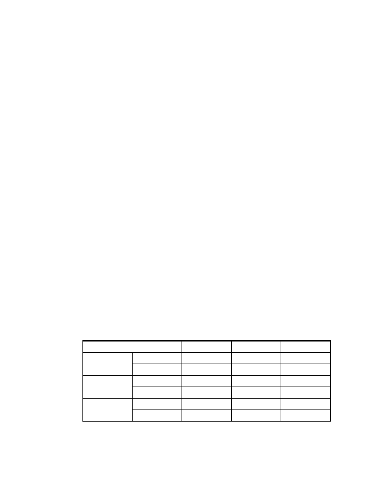
Table 1-1 Maximum configurations for the X6 systems
Maximum configurations x3750 M4 x3850/x3950 X5 x3850/x3950 X6
Form factor 4 socket 2U 4U 4U
Processors 1-node 4 4 4
Cores 1-node 32 40 60
8 socket Not available 8U 8U
2-node Not available 8 8
6 IBM System x3850 X6 and x3950 X6 Planning and Implementation Guide
2-node Not available 80 120
Page 23

Maximum configurations x3750 M4 x3850/x3950 X5 x3850/x3950 X6
Memory 1-node 48 DIMM slots
1-node with
MAX5
2-node Not available 128 DIMM slots
Not available 96 DIMM slots
a
64 DIMM slots
a
96 DIMM slots
a
Not available
a
192 DIMM slots
a
a
2.5-inch drive
bays
1.8-inch SSDs
drive bays
Standard 1Gb
Ethernet
interfaces
Standard 10Gb
Ethernet
interface
USB ports 1-node 4 USB 2.0 8 USB 2.0 6 USB 2.0, 2 USB
Power supplies 1-node 2 x 1400W 2 x 1975W 4 x 900W or
a. Requires all processors to be installed in order to use all memory slots.
b. Model dependent.
c. Mixing of power supplies in pairs is supported.
1-node 16 8 8
2-node Not available 16 16
1-node 32 16 16
2-node Not available 32 32
1-node 2 2
2-node Not available 4 8 (Optional)
1-node 2 (Optional) 2 2 (Optional)
2-node Not available 4 4 (Optional)
2-node Not available 16 USB 2.0 12 USB 2.0, 4
2-node Not available 4 x 1975W 8 x 900W or
b
4 (Optional)
3.0
USB 3.0
c
1400W
c
1400W
1.4 Storage versus in-memory data
Main memory (RAM) is the fastest storage type that can hold a significant amount of data.
Data in main memory can be accessed more than a hundred thousand times faster than data
on a spinning hard disk, and even flash technology storage is about a thousand times slower
than main memory.
Main memory is connected directly to the processors through a high-speed bus, whereas
hard disks are connected through a chain of buses (QPI, PCIe, SAN) and controllers (I/O hub,
RAID controller or SAN adapter, and storage controller).
Compared to keeping data on disk, keeping the data in main memory can dramatically
improve database performance just by the advantage in access time. However, there is one
potential drawback. In a database transaction that has been committed, the transaction
cannot stay committed.
Chapter 1. Introduction 7
Page 24

In database technology, atomicity, consistency, isolation, and durability (ACID) is a set of
requirements that guarantees that database transactions are processed reliably:
A transaction must be atomic. That is, if part of a transaction fails, the entire transaction
has to fail and leave the database state unchanged.
The consistency of a database must be preserved by the transactions that it performs.
Isolation ensures that no transaction interferes with another transaction.
Durability means that after a transaction is committed, it will remain committed.
Although the first three requirements are not affected by the in-memory concept, durability is
a requirement that cannot be met by storing data in main memory alone. This is because
main memory is volatile storage. That is, it loses its content when no electrical power is
present. To make data persistent, it must reside on non-volatile storage. Therefore, some sort
of permanent storage is still needed such as hard drives, solid-state drives (SSDs), or flash
devices to form a hybrid solution that uses both in-memory and disk technology together.
The advantage of a hybrid solution can mean flexibility by being able to balance the
performance, cost, and persistence and form factor, in the following ways:
Performance: Use in-memory technology to enhance performance of sorting, storing, and
retrieving specified data rather than going to disk
Persistence and form factor: Memory cannot approach the density of a small hard drive
Cost: Less costly hard-disks can be substituted for more memory
In the next section, we discuss IBM technologies for flash storage.
1.5 Flash storage
IBM flash storage offerings for X6 servers combine extreme IOPS performance and low
response time for transactional database workloads. The flash technologies used in the X6
servers include IBM eXFlash DIMMs, IBM eXFlash SSDs, and IBM FlashCache Storage
Accelerator.
IBM eXFlash memory-channel storage:
IBM eXFlash DIMMs represent innovative technology that utilizes DDR3 memory
channels to connect flash storage modules. IBM is the first company that will deploy
memory-channel storage technology in their industry-standard servers.
These are key features of eXFlash DIMMs:
– eXFlash DIMMs will be accessed through standard DDR3 memory channels.
– eXFlash DIMMs will be interoperable with standard RDIMMs in the same channel.
– eXFlash DIMMs will be supported by the major operating systems through software
drivers.
– The projected capacity and performance of the eXFlash DIMMs will allow up to 25 TB
of a DDR3-based flash storage in a single x3950 X6 with up to 10 million random read
IOPS and more than 4 million random write IOPS.
IBM eXFlash SSDs:
IBM eXFlash solid-state drives have an innovative high-density design of the drive cages
and the performance-optimized storage controllers with the reliable high-speed solid-state
drive technology.
8 IBM System x3850 X6 and x3950 X6 Planning and Implementation Guide
Page 25

IBM FlashCache Storage Accelerator:
IBM FlashCache Storage Accelerator is an all-in-one flash-caching product that leverages
the speed, management, capacity, and breadth of the IBM High IOPS adapters and
qualified SSDs and integrates them into a high speed server-side caching service that
seamlessly accelerates the most important data with little or minimal IT overhead in both
physical and virtual servers.
These new technologies will allow IBM X6 servers to deliver break-through performance for
targeted workloads by offering significantly lower latency and higher performance compared
to traditional solid-state drives.
For additional information about IBM flash storage solutions, see the following sections:
2.6.3, “IBM eXFlash SSD technology” on page 40
2.6.2, “IBM eXFlash memory-channel storage” on page 38
2.6.5, “IBM FlashCache Storage Accelerator” on page 42
1.6 Energy efficiency
The x3850 X6 and x3950 X6 offer the following energy-efficiency features to save energy,
reduce operational costs, increase energy availability, and contribute to the green
environment:
Energy-efficient electronic components help lower operational costs.
Highly efficient 900 W AC and 1400 W AC power supplies have 80 PLUS Platinum
certification.
Intel Xeon processor E7-4800/8800 v2 product families offer significantly better
performance over the previous generation while fitting into the same thermal design power
(TDP) limits.
Intel Intelligent Power Capability powers individual processor elements on and off as
needed, to reduce power draw.
Low-voltage Intel Xeon processors draw less energy to satisfy the demands of power and
thermally constrained data centers and telecommunication environments.
Low-voltage 1.35 V DDR3 memory RDIMMs consume 15% less energy compared to 1.5
V DDR3 RDIMMs.
Solid state drives (SSDs) consume as much as 80% less power than traditional spinning
2.5-inch HDDs.
The server uses hexagonal ventilation holes, which is a part of IBM Calibrated Vectored
Cooling™ technology. Hexagonal holes can be grouped more densely than round holes,
providing more efficient airflow through the system.
IBM Systems Director Active Energy Manager™ provides advanced data center power
notification and management to help achieve lower heat output and reduced cooling
needs.
Chapter 1. Introduction 9
Page 26

1.7 Services offerings
The X6 systems fit into the services offerings that are already available from IBM Global
Technology Services® for System x and BladeCenter. More information about these services
is available at the following website:
http://www.ibm.com/systems/services/gts/systemxbcis.html
In addition to the existing offerings for asset management, information infrastructure, service
management, security, virtualization, and consolidation, and business and collaborative
solutions; IBM Systems Lab Services and Training has six offerings specifically for X6:
Virtualization Enablement
Database Enablement
Enterprise Application Enablement
Migration Study
Virtualization Health Check
Rapid! Migration Tool
IBM Systems Lab Services and Training is a worldwide services team of deeply skilled,
experienced consultants and instructors who assist clients in the acceleration of adopting new
IBM products and offerings, maximizing the performance of their IBM Systems and solutions,
and enabling operational excellence through the transfer of skills and knowledge to the
clients' staffs. The services offerings are designed around having the flexibility to be
customized to meet your needs and can provide preconfigured services, custom services,
expert skills transfer, off-the-shelf training, and online/classroom courses for X6.
For more information, send an email to this address:
mailto:stgls@us.ibm.com
Also, more information is available at the following website:
http://www.ibm.com/systems/services/labservices
1.8 What this book contains
In this book, readers get a general understanding of X6 technology, which sets it apart from
previous models, and the architecture that makes up this product line. This book is broken
down into several chapters:
The first three chapters give an in-depth look at the X6 hardware and architecture:
Chapter 1: A high-level overview of X6 and its target workloads/markets
Chapter 2: New technology in X6
Chapter 3: An in-depth look at key components, such as memory, CPU, storage, and I/O
The last four chapters describe preparing and implementing the X6 server. We describe
power and cooling considerations, operating installations, systems management, and
firmware update tools:
Chapter 4: Rack, power, and cooling considerations for X6.
Chapter 5: Preparing the X6 hardware for use.
Chapter 6: Operating system installation guidelines.
Chapter 7: How to manage your X6 hardware.
10 IBM System x3850 X6 and x3950 X6 Planning and Implementation Guide
Page 27

Chapter 2. Technology
2
In this chapter, we give an overview of the technologies that IBM includes in the IBM System
x3850 X6 and x3950 X6 servers. We describe system architecture and new chassis design
with modular structure and the latest Intel Xeon E7-4800 v2 and E7-8800 v2 processors.
Then we describe the current memory options and features of the storage subsystem,
including innovative memory-channel storage technology implemented as IBM eXFlash
DIMMs. We discuss other advanced technology in the servers and describe X6 scaling and
partitioning capabilities.
This chapter contains the following topics:
2.1, “Modular design” on page 12
2.2, “System architecture” on page 19
2.3, “Processors” on page 23
2.4, “Memory” on page 30
2.5, “PCIe 3.0” on page 37
2.6, “Internal storage” on page 38
2.7, “UEFI” on page 44
2.8, “Integrated Management Module” on page 44
2.9, “Scalability” on page 45
© Copyright IBM Corp. 2014. All rights reserved. 11
Page 28
2.1 Modular design
IBM X6 rack family consists of the new flagship servers of the IBM x86 server family:
IBM System x3850 X6: 4U rack-optimized server scalable to four sockets
IBM System x3950 X6: 8U rack-optimized server scalable to eight sockets
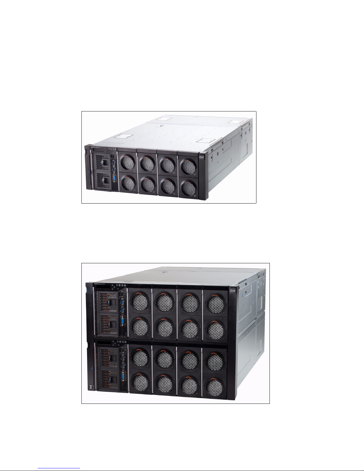
Figure 2-1 shows the IBM System x3850 X6.
Figure 2-1 IBM System x3850 X6
The x3950 X6 looks like two x3850 X6 servers where one is placed on top of the other.
However, unlike eX5 servers, x3950 X6 employs a single chassis with a single midplane
design without any external connectors and cables.
Figure 2-2 shows the IBM System x3950 X6.
Figure 2-2 IBM System x3950 X6
12 IBM System x3850 X6 and x3950 X6 Planning and Implementation Guide
Page 29
The X6 systems offer a new “bookshelf” design concept that is based on a fixed chassis
mounted in a standard rack cabinet. There is no need to pull the chassis in or out of the rack
to access components because all components can be accessed either from the front or from
the rear like pulling books from a bookshelf.
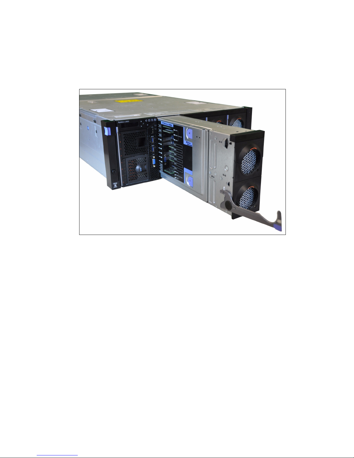
Figure 2-3 shows the x3850 X6 server with one of the four Compute Books partially removed.
Figure 2-3 IBM x3850 X6 server with a Compute Book partially removed
The modular component that can be installed in a chassis is called a book. There are several
types of books available:
Compute Books:
A Compute Book contains one processor, 24 DIMM slots, and 2 hot-swap fan modules.
It is accessible from the front of the server.
The x3850 X6 supports up to four Compute Books. The x3950 X6 supports up to eight
Compute Books.
Storage Books:
The Storage Book contains standard 2.5-inch drives or IBM eXFlash 1.8-inch hot-swap
SSD drives. It also provides front USB and video ports, and it has two PCIe slots reserved
for internal storage adapters. The Storage Book is accessible from the front of the server.
The x3850 X6 has one Storage Book. The x3950 X6 has two Storage Books.
I/O Books:
An I/O Book is a container that provides PCIe expansion capabilities. I/O Books are
accessible from the rear of the server.
There are three types of I/O Books:
– Primary I/O Book. This book provides core I/O connectivity, including the ML2 unique
slot for an onboard network, three standard PCIe 3.0 slots, Integrated Management
Module II, hot-swap fan modules and USB, video, serial, and systems management
ports.
Chapter 2. Technology 13
Page 30
– Full-length I/O Book. This hot-swap book provides three optional full-length PCIe slots,
Storage Book Compute Books
Primary I/O Book
Additional I/O Books
Power supplies
and two of them are capable of hosting a Graphics Processing Unit (GPU) or
co-processor adapters with a total power consumption of 300 W.
– Half-length I/O Book. This hot-swap book provides three optional half-length PCIe
slots.
The x3850 X6 has one Primary I/O Book and supports one or two of the full or half-length
I/O Books (one of each or two of either). The x3950 X6 has two Primary I/O Books and
supports up to four of the full or half-length I/O Books (any combination).
2.1.1 Compute Books
Overall, the x3850 X6 server has up to four Compute Books, one Storage Book, one Primary
I/O Book, and up to two optional I/O Books. In addition, the 4U chassis supports up to four
power supplies and up to ten hot-swap dual-motor fans (eight fans on the front and two fans
on the rear).
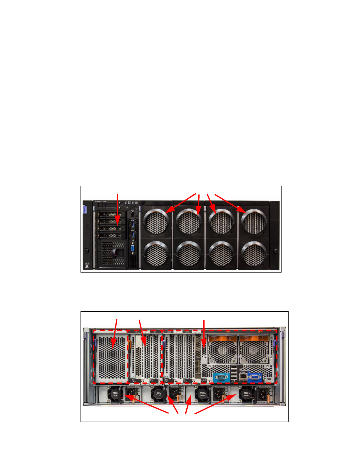
Figure 2-4shows the front of the x3850 X6 server where you can see the four Compute Books
and the Storage Book.
Figure 2-4 x3850 X6 front view
Figure 2-5 shows the rear view of the x3850 X6 server where you can see the Primary I/O
Book, additional I/O Books, and power supplies.
Figure 2-5 x3850 X6 rear view
14 IBM System x3850 X6 and x3950 X6 Planning and Implementation Guide
Page 31

In the middle of the server, there is a passive midplane that connects all modular components
Compute Book with
the side cover
removed showing 12
of the 24 DIMM
sockets (the other 12
are on the other side
of the book.
to each other. Figure 2-6 shows the x3850 X6 midplane:
Figure 2-6 x3850 X6 midplane (front side showing Compute Book connections)
Each Compute Book contains one Intel Xeon processor, 24 memory DIMMs, and two
dual-motor fans. 24 DIMM slots are located on both sides of the Compute Book’s processor
board, 12 memory modules on each side.
Figure 2-7 shows the Compute Book with the clear side cover removed. The front of the
Compute Book are two hot-swap fans.
Figure 2-7 The Compute Book
The x3850 X6 server supports up to four Compute Books; the x3950 X6 server supports up to
8 Compute Books. For more information about the Compute Books, see 3.6, “Compute Book”
on page 64.
Chapter 2. Technology 15
Page 32

2.1.2 Storage Book
The Storage Book is accessible from the front of the server. The Storage Book has bays for
1.8-inch (up to 16) or 2.5-inch drives (up to 8), two slots for RAID controllers to connect to
those drive bays, a front operator panel, and USB and video ports. Figure 2-8 shows the
Storage Book.
Figure 2-8 The Storage Book
The x3850 X6 server has one Storage Book; the x3950 X6 has two Storage Books. For more
information about the Storage Book, see 3.10.1, “Storage Book” on page 75.
2.1.3 Primary I/O Book
The Primary I/O Book is the third core module, which provides base I/O connectivity, including
four PCIe slots:
Three standard PCIe 3.0 half-length slots.
A single slot for an ML2 form-factor network adapter
The Primary I/O Book also contains core logic such as the Integrated Management Module II
(IMM2) and UEFI, fan modules, and peripheral ports. The Primary I/O Book installs in the rear
of the server.
16 IBM System x3850 X6 and x3950 X6 Planning and Implementation Guide
Page 33

Figure 2-9 shows the internals of the Primary I/O Book, as viewed from the front of the server.
The black air baffle is raised to show internal components.
Figure 2-9 The Primary I/O Book internals
The x3850 X6 has one Primary I/O Book. The x3950 X6 has two Primary I/O Books. For more
information about the Primary I/O Book, see 3.12, “Primary I/O Book” on page 85.
2.1.4 Additional I/O Books
Additional I/O Books provide additional I/O capabilities, each with 3 PCIe slots. There are two
types of additional I/O Books:
Half-length I/O Book, supporting three half-length adapters
Full-length I/O Book, supporting either full-length or half-length adapters.
The Full-length I/O Book is designed to accept GPU adapters and co-processors, including
double-wide adapters that require up to 300W of power. The Full-length I/O Book includes
two auxiliary power connectors, 150W and 75W, as well as power cables.
Chapter 2. Technology 17
Page 34

These I/O Books are accessible from the rear of the server. Figure 2-10 shows the two I/O
Half-length I/O Book
Full-length I/O Book
Books.
2.1.5 Power supplies
Figure 2-10 Additional I/O Books
The x3850 X6 server supports up to two additional I/O Books of any type; the x3950 X6
server supports up to four additional I/O Books.
For more information about the additional I/O Books, see 3.13.1, “Half-length I/O Book” on
page 89 and 3.13.2, “Full-length I/O Book” on page 89.
The x3850 X6 has also up to four hot-swap redundant power supplies of several types:
1400W AC, 900W AC, and 750W -48V DC. The x3950 X6 has up to eight power supplies,
900W AC or 1400W AC. Figure 2-11 shows a 1400W AC power supply.
Figure 2-11 1400W power supply
18 IBM System x3850 X6 and x3950 X6 Planning and Implementation Guide
Page 35

For more information about the additional power supplies, see 3.22, “Power subsystem” on
SMI
links
MB 2
MB 1
X6 DDR3
Compute Book
QPI links
Intel
Xeon
CPU 1
MB 2
MB 1
MB 2
MB 1
MB 2
MB 1
MB 2
MB 1
DMI
links
Slot 7: PCIe 3.0 x16 (x16)
Slot 9: PCIe 3.0 x16 (x16)
MB 2
MB 1
MB 2
MB 1
MB 2
MB 1
8x USB
Serial
Management
Video
IMM2
PCIe x1
Slot 10: Mezz LOM (x8)
Slot 12: PCIe 3.0 x16 (x8)
Intel
Xeon
CPU 2
Slot 8: PCIe 3.0 x16 (x8)
Slot 11: PCIe 3.0 x16 (x8)
Intel
Xeon
CPU 4
Intel
Xeon
CPU 3
Slot 1: PCIe 3.0 x16 (x16)
Slot 2: PCIe 3.0 x8 (x8)
Slot 3: PCIe 3.0 x8 (x8)
Slot 4: PCIe 3.0 x16 (x16)
Slot 5: PCIe 2.0 x8 (x8)
Slot 6: PCIe 3.0 x16 (x16)
Storage Book
Primary I/O Book
PCIe 3.0 lanes
Full Length I/O Book
Half Length I/O Book
PCIe 3.0 lanes
Intel
I/O Hub
PCIe
switch
page 101.
2.2 System architecture
This section shows the overall architecture of both the x3850 X6 and x3950 X6.
2.2.1 x3850 X6
Figure 2-12 shows the system architecture of the x3850 X6 server.
Figure 2-12 x3850 X6 system architecture
Processor-to-processor communication is carried over shared-clock or coherent quick path
interconnect (QPI) links. Each processor has three QPI links to connect to other processors.
Chapter 2. Technology 19
Page 36

Figure 2-13 shows how the four processors of the x3850 X6 are connected via QPI links. In
4 3
21
x3850 X6 - 4 sockets
this configuration, each processor is directly connected to all other processors.
Figure 2-13 QPI links between processors
In the Compute Book, each processor has four Scalable Memory Interconnect Generation 2
(SMI2) channels (two memory controllers per processor, each with two SMI channels) that
are connected to four scalable memory buffers. Each memory buffer (MB) has six DIMM slots
(two channels with three DIMMs per channel) for a total of 24 DIMMs (eight channels with
three DIMMs per channel) per processor. Compute Books are connected to each other via
Quick Path Interconnect (QPI) links.
The Primary I/O Book has three PCIe 3.0 slots, Mezzanine LOM slot, I/O Controller Hub,
Integrated Management Module II (IMM2) and peripheral ports (such as USB, video, serial)
on the board. Additional I/O Books (Full-length and Half-length) have three PCIe 3.0 slots
each and provide ability to hot-add and hot-remove PCIe adapters.
Additional I/O Books: For illustration purposes, both Half-length and Full-length I/O
Books are shown in Figure 2-12, where the Half-length I/O Book supplies slots 1, 2, and 3,
and the Full-length I/O Book supplies slots 4, 5, and 6. The Half-length I/O Book can also
be used to supply slots 4, 5, and 6, and the Full-length I/O Book can also be used to supply
slots 1, 2, and 3.
The Primary I/O Book is connected to the Compute Books 1 (CPU 1) and 2 (CPU 2) directly
via PCIe links from those processors: PCIe slots 9 and 10 are connected to CPU 1, and PCIe
slots 7 and 8 are connected to CPU 2. Also, both CPU 1 and CPU 2 are connected to the Intel
I/O Hub via Direct Media Interface (DMI) switched links for redundancy purposes.
The Storage Book is also connected to both Compute Books 1 and 2, however, the PCIe slots
11 and 12 are connected to different processors (CPU 2 and CPU 1 respectively). In addition,
certain peripheral ports are routed from the Intel I/O Hub and IMM2 to the Storage Book.
Additional I/O Books are connected to Compute Books 3 and 4 and use PCIe links from
CPU 3 and CPU 4. If you need to install additional I/O Books, you should install the Compute
Book in an appropriate slot first.
The System x3850 X6 server is designed so that it can tolerate the failure of CPU 1. This
feature decreases downtime in the event of a processor failure, and it requires two Compute
Books installed in Compute Book slots 1 and 2, and an OS boot path from the CPU in
Compute Book 2. Downtime is decreased by allowing the machine to boot on another
processor until time can be taken to engage IBM service.
When the server detects a failure of CPU 1, the IMMv2 reroutes the Intel I/O Hub to CPU 2
instead. The system will boot using CPU 2, albeit with reduced functionality. This failover to a
surviving processor is automatic and is handled by the system at boot time.
20 IBM System x3850 X6 and x3950 X6 Planning and Implementation Guide
Page 37

If you want to take advantage of this recovery, it is important to carefully plan your network
SMI
links
MB 2
MB 1
X6 DDR3
Compute Book
QPI links
MB 2
MB 1
MB 2
MB 1
MB 2
MB 1
MB 2
MB 1
DMI links
Slot 7: PCIe 3.0 x16 (x16)
Slot 9: PCIe 3.0 x16 (x16)
MB 2
MB 1
MB 2
MB 1
MB 2
MB 1
8x USB
Serial
Management
Video
IMM2
PCIe x1
Slot 10: Mezz LOM (x8)
Slot 12: PCIe 3.0 x16 (x8)
Slot 8: PCIe 3.0 x16 (x8)
Slot 11: PCIe 3.0 x16 (x8)
Slot 1: PCIe 3.0 x16 (x16)
Slot 2: PCIe 3.0 x8 (x8)
Slot 3: PCIe 3.0 x8 (x8)
Slot 4: PCIe 3.0 x16 (x16)
Slot 5: PCIe 2.0 x8 (x8)
Slot 6: PCIe 3.0 x16 (x16)
Storage Book
Primary I/O Book
PCIe 3.0 lanes
Full Length I/O Book
Half Length I/O Book
PCIe 3.0 lanes
Intel
Xeon
CPU 3
Intel
Xeon
CPU 4
Intel
Xeon
CPU 1
Intel
Xeon
CPU 2
QPI link (to CPU 7)
QPI link (to CPU 8)
QPI link (to CPU 5)
QPI link (to CPU 6)
PCIe
switch
Intel
I/O Hub
and storage connectivity, because if CPU 1 fails, PCIe slots 9, 10, and 12 become
unavailable.
2.2.2 x3950 X6
The x3950 X6 server has the same architecture adapted to 8-socket configuration.
Figure 2-14 and Figure 2-15 show the system architecture of the x3950 X6 server
(Figure 2-15 shows the upper half, and Figure 2-14 shows the lower half).
Figure 2-14 x3950 X6 (bottom half)
Chapter 2. Technology 21
Page 38

Figure 2-15 x3950 X6 system architecture (top half)
SMI
links
MB 2
MB 1
X6 DDR3
Compute Book
QPI links
MB 2
MB 1
MB 2
MB 1
MB 2
MB 1
MB 2
MB 1
DMI links
Slot 39: PCIe 3.0 x16 (x16)
Slot 41: PCIe 3.0 x16 (x16)
MB 2
MB 1
MB 2
MB 1
MB 2
MB 1
8x USB
Serial
Management
Video
IMM2
PCIe x1
Slot 42: Mezz LOM (x8)
Slot 44: PCIe 3.0 x16 (x8)
Slot 40: PCIe 3.0 x16 (x8)
Slot 43: PCIe 3.0 x16 (x8)
Slot 33: PCIe 3.0 x16 (x16)
Slot 34: PCIe 3.0 x8 (x8)
Slot 35: PCIe 3.0 x8 (x8)
Slot 36: PCIe 3.0 x16 (x16)
Slot 37: PCIe 2.0 x8 (x8)
Slot 38: PCIe 3.0 x16 (x16)
Storage Book
Primary I/O Book
PCIe 3.0 lanes
Full Length I/O Book
Half Length I/O Book
PCIe 3.0 lanes
QPI link (to CPU 2)
QPI link (to CPU 3)
QPI link (to CPU 4)
QPI link (to CPU 1)
PCIe
switch
Intel
I/O Hub
Intel
Xeon
CPU 7
Intel
Xeon
CPU 8
Intel
Xeon
CPU 5
Intel
Xeon
CPU 6
4 3
21
7 8
56
x3950 X6 - 8 sockets
The 8-socket configuration is formed using the native QPI scalability of the Intel Xeon
processor E7 family.
Figure 2-16 shows how the processors are connected together using QPI links.
22 IBM System x3850 X6 and x3950 X6 Planning and Implementation Guide
Figure 2-16 QPI connectivity - x3950 X6 with 8 processors installed
Page 39

The x3950 X6 is an eight-socket server but also supports four and six processors installed.
x3950 X6 with 4 processors
2156
5 6
21
3
21
7
56
x3950 X6 with 6 processors
5 6
21
7
3
Figure 2-17 shows the x3950 X6 with only 4 processors installed. On the right of the figure,
the effective connectivity is shown, where each processor is connected either directly to a
processor or one hop away.
Figure 2-17 QPI connectivity - x3950 X6 with 4 processors installed
Figure 2-18 shows the x3950 X6 with only 6 processors installed. On the right of the figure,
the effective connectivity is shown, where each processor is connected either directly to a
processor or one hop away.
Figure 2-18 QPI connectivity - x3950 X6 with 6 processors installed
In addition, the 8-socket server has ability to form two independent systems containing four
socket in each node, such as two independent x3850 X6 servers in one 8U chassis. This
partitioning feature is enabled using the IMM2 interface. While partitioning is enabled, each
partition can deploy its own operating system. Each partition uses its own resources and can
no longer access the other partition’s resources.
2.3 Processors
The current models of the X6 systems use the Intel Xeon processor E7-4800/8800 v2 product
family. The Intel Xeon processors that are used in the X6 systems are follow-ons to the Intel
Xeon processor E7-4800/8800 product family. The new processors feature the new Intel
microarchitecture (formerly codenamed “IvyBridge-EX”) and the new 22 nm manufacturing
process that provide higher core count, larger cache sizes, higher core frequencies, and
higher memory speeds. In addition, these new processors support more memory with up to
24 DIMMs per processor and faster low-latency I/O with integrated PCIe 3.0 controllers.
Chapter 2. Technology 23
Page 40

2.3.1 Intel Xeon processor E7-4800/8800 v2 product family
There are two groups of the Intel Xeon processor E7 family that are used in the X6 servers
and support scaling to separate levels:
The Intel Xeon processor E7-4800 v2 product family is used in the x3850 X6. This family
supports four-processor configurations.
The Intel Xeon processor E7-8800 v2 product family is used in the x3950 X6 to scale to
eight-socket configurations.
The X6 systems support the latest generation of the Intel Xeon processor E7-4800 v2 and
E7-8800 v2 product family, which offers the following key features:
Up to 15 cores and 30 threads (using Hyper-Threading feature) per processor
Up to 37.5 MB of L3 cache
Up to 3.4 GHz core frequencies
Up to 8 GT/s bandwidth of QPI links
Integrated memory controller with four SMI2 channels that support up to 24 DDR3 DIMMs
Up to 1600 MHz DDR3 memory speeds and up to 2667 MHz SMI link speeds
Integrated PCIe 3.0 controller with 32 lanes per processor
Intel Virtualization Technology (VT-x and VT-d)
Intel Turbo Boost Technology 2.0
Intel Advanced Vector Extensions (AVT)
Intel AES-NI instructions for accelerating of encryption
Advanced QPI and memory reliability, availability, and serviceability (RAS) features
Machine Check Architecture recovery (non-execution and execution paths)
Enhanced Machine Check Architecture Gen1
Machine Check Architecture I/O
Security technologies: OS Guard, Secure Key, Intel TXT
Table 2-1 compares the Intel Xeon processor E7-4800/8800 v2 product families used in X6
systems with the Intel Xeon processor E7-4800/8800 product families that are used in IBM
eX5 servers.
Table 2-1 eX5 and X6 processors comparisons
Feature eX5 family X6 family
Processor family Intel Xeon E7-8800
Intel Xeon E7-4800
Processor codenames Westmere EX Ivy Bridge EX
Cores per CPU Up to 10 cores Up to 15 cores
Last level cache Up to 30 MB L3 cache Up to 37.5 MB L3 cache
QPI QPI 1.0 at 6.4 GT/s max QPI 1.1 at 8.0 GT/s max
CPU TDP rating Up to 130W Up to 155W
DIMM sockets 16 DIMMs per CPU 24 DIMMs per CPU
Maximum memory speeds 1067 MHz DDR3 2667 MHz SMI2
PCIe technology PCIe 2.0 (5 GT/s) PCIe 3.0 (8 GT/s)
24 IBM System x3850 X6 and x3950 X6 Planning and Implementation Guide
Intel Xeon E7-8800 v2
Intel Xeon E7-4800 v2
Page 41

The new Intel Xeon processors feature advanced technologies described next.
Intel Advanced Encryption Standard - New Instructions
Advanced Encryption Standard (AES) is an encryption standard that is widely used to protect
network traffic and sensitive data. Advanced Encryption Standard - New Instructions
(AES-NI), available with the E7 processors, implements certain complex and performance
intensive steps of the AES algorithm by using processor hardware. AES-NI can accelerate
the performance and improve the security of an implementation of AES over an
implementation that is completely performed by software.
For more information about Intel AES-NI, visit the following web page:
http://software.intel.com/en-us/articles/intel-advanced-encryption-standard-instru
ctions-aes-ni
Intel Virtualization Technology
Intel Virtualization Technology (Intel VT) is a suite of processor and I/O hardware
enhancements that assists virtualization software to deliver more efficient virtualization
solutions and greater capabilities.
Intel Virtualization Technology for x86 (Intel VT-x) allows the software hypervisors to better
manage memory and processing resources for virtual machines (VMs) and their guest
operating systems.
Intel Virtualization Technology for Directed I/O (Intel VT-d) helps improve I/O performance
and security for VMs by enabling hardware-assisted direct assignment and isolation of I/O
devices.
For more information about Intel Virtualization Technology, visit the following web page:
http://www.intel.com/technology/virtualization
Hyper-Threading Technology
Intel Hyper-Threading Technology enables a single physical processor to run two separate
code streams (threads) concurrently. To the operating system, a processor core with
Hyper-Threading is seen as two logical processors. Each processor has its own architectural
state, that is, its own data, segment, and control registers, and its own advanced
programmable interrupt controller (APIC).
Each logical processor can be individually halted, interrupted, or directed to run a specified
thread, independently from the other logical processor on the chip. The logical processors
share the execution resources of the processor core, which include the execution engine, the
caches, the system interface, and the firmware.
Hyper-Threading Technology is designed to improve server performance. This process is
done by using the multi-threading capability of operating systems and server applications in
such a way as to increase the use of the on-chip execution resources available on these
processors. Application types that make the best use of Hyper-Threading are virtualization,
databases, e-mail, Java, and web servers.
For more information about Hyper-Threading Technology, visit the following web page:
http://www.intel.com/technology/platform-technology/hyper-threading
vSphere 5.1 and 8-socket systems: VMware vSphere 5.1 has a fixed upper limit of 160
concurrent threads. This means if you are using an 8-socket system, with more than 10
cores per processor, you should disable Hyper-Threading.
Chapter 2. Technology 25
Page 42

Turbo Boost Technology 2.0
4 3
21
7 8
56
4 3
21
x3950 X6 - 8 sockets
x3850 X6
4 sockets
The Intel Xeon E7-8800/4800 v2 processor family brings enhanced capabilities of changing
processor speed with new generation of Intel Turbo Boost 2.0 technology.
Intel Turbo Boost Technology dynamically saves power on unused processor cores and
increases the clock speed of the cores in use. Depending on current workload, Intel Turbo
Boost Technology allows a dynamic increase in the clock speed of the active cores to gain a
performance boost. For example, a 3.4GHz 15-core processor can overclock the cores up to
3.7 GHz.
Turbo Boost Technology is available on a per-processor basis for the X6 systems. For
ACPI-aware operating systems and hypervisors such as Microsoft Windows 2008/2012,
RHEL 5/6, SLES 11, VMware ESXi 4.1, and later, no changes are required to take advantage
of it. Turbo Boost Technology can be engaged with any number of cores enabled and active,
resulting in increased performance of both multi-threaded and single-threaded workloads.
Turbo Boost Technology dynamically saves power on unused processor cores and increases
the clock speed of the cores in use. In addition, it can temporarily increase speed of all cores
by intelligently managing power and thermal headroom. For example, a 2.5 GHz 15-core
processor (E7-8880 v2) can temporarily run all 15 active cores at 2.9 GHz. With only two
cores active, the same processor can run those active cores at 3.0 GHz. When the cores are
needed again, they are turned back on dynamically and the processor frequency is adjusted
accordingly.
When temperature, power, or current exceeds factory-configured limits and the processor is
running above the base operating frequency, the processor automatically steps the core
frequency back down to reduce temperature, power, and current. The processor then
monitors temperature, power, and current, and re-evaluates. At any given time, all active
cores run at the same frequency.
For more information about Turbo Boost Technology, go to the following website:
http://www.intel.com/technology/turboboost/
QuickPath Interconnect
The Intel Xeon E7 processors implemented in IBM X6 servers include two integrated memory
controllers in each processor. Processor-to-processor communication is carried over
shared-clock or coherent quick path interconnect (QPI) links. Each processor has three QPI
links to connect to other processors.
Figure 2-19 shows the QPI configurations. On the left is how the four sockets of the x3850 X6
are connected together. On the right is how all eight sockets of the x3950 X6 are connected
together.
Figure 2-19 QPI links between processors
26 IBM System x3850 X6 and x3950 X6 Planning and Implementation Guide
Page 43

Each processor has some amount of memory, connected directly to the processor. To access
memory connected to another processor, each processor uses QPI links through another
processors. This design creates a non-uniform memory access (NUMA) system. Similarly, I/O
can be local to a processor or remote through another processor.
For QPI use, Intel modified the MESI cache coherence protocol to include a forwarding state.
Therefore, when a processor asks to copy a shared cache line, only one other processor
responds.
For more information about QPI, visit the following web page:
http://www.intel.com/technology/quickpath
Intel Data Direct I/O
For I/O, Intel no longer has a separate I/O hub. It now integrates PCI Express 3.0 I/O into the
processor itself. Data Direct I/O helps to optimize data transfer between local CPU and PCIe
devices. The combination of Data Direct I/O and PCI 3.0 provides a significantly higher I/O
performance with lower latencies and reduced power consumption.
For more information about Data Direct I/O, visit the following web page:
http://www.intel.com/content/www/us/en/io/direct-data-i-o.html
RAS features
The Intel Xeon processor E7 family of processors has additional reliability, availability, and
serviceability (RAS) features on their interconnect links (SMI and QPI):
Cyclic redundancy checking (CRC) on the QPI links:
The data on the QPI link is checked for errors.
QPI packet retry:
If a data packet on the QPI link has errors or cannot be read, the receiving processor can
request that the sending processor try resending the packet.
QPI clock failover:
If there is a clock failure on a coherent QPI link, the processor on the other end of the link
can become the clock. This action is not required on the QPI links from processors to I/O
hubs, as these links are asynchronous.
QPI self-healing:
If there are persistent errors detected on a QPI link, the link width can be reduced
dynamically to allow the system to run in a degraded mode until repair can be performed.
QPI link can reduce its width to a half width or a quarter width, and slowdown its speed.
Scalable memory interconnect (SMI) packet retry:
If a memory packet has errors or cannot be read, the processor can request that the
packet be resent from the memory buffer.
Chapter 2. Technology 27
Page 44

Machine Check Architecture recovery
The Intel Xeon processor E7 family also features Machine Check Architecture (MCA)
recovery, a RAS feature that enables the handling of system errors that otherwise require that
the operating system be halted. For example, if a dead or corrupted memory location is
discovered, but it cannot be recovered at the memory subsystem level, and provided it is not
in use by the system or an application, an error can be logged and the operation of the server
can continue. If it is in use by a process, the application to which the process belongs can be
stopped or informed about the situation.
Implementation of the MCA recovery requires hardware support, firmware support (such as
found in the UEFI), and operating system support. Microsoft, SUSE, Red Hat, VMware, and
other operating system vendors include or plan to include support for the Intel MCA recovery
feature on the Intel Xeon processors in their latest operating system versions.
The following new MCA recovery features of the Intel Xeon processor E7-4800/8800 v2
product family are included:
Execution path recovery: Ability to work with hardware and software to recognize and
isolate the errors that were delivered to the execution engine (core).
Enhanced MCA (eMCA) Generation 1: Provides enhanced error log information to the
operating system, hypervisor, or application that can be used to provide better diagnostic
and predictive failure analysis for the system. This enables higher levels of uptime and
reduced service costs.
Security improvements
The Intel Xeon E7-4800/8800 v2 processor family has several important security
improvements that help to protect systems from different types of security threats.
Intel OS Guard: Evolution® of Intel Execute Disable Bit technology, which helps to protect
from escalation of privilege attacks by preventing code execution from userspace memory
pages while in kernel-mode. It helps to protect from certain types of malware attacks.
Intel Trusted Execution Technology (Intel TXT), Intel VT-x, and Intel VT-d: New
hardware-based techniques, which allow you to isolate virtual machines and boot VMs
only in a trusted environment. In addition, malware infected VMs cannot affect another
VMs on the same host.
Intel Secure Key: Provides hardware random numbers generation without storing any data
in system memory. It keeps generated random numbers out of sight of malware and
therefore enhances encryption protection.
For more information, read the following Intel White Paper:
http://www.intel.com/content/dam/www/public/us/en/documents/white-papers/3rd-gen-c
ore-vpro-security-paper.pdf
28 IBM System x3850 X6 and x3950 X6 Planning and Implementation Guide
Page 45

2.3.2 Compute Books
Compute book with the
side cover attached
The core modular element of the X6 design is a Compute Book. It contains the following
components:
One Intel Xeon processor E7-4800 v2/8800 v2 product families processor
24 memory DIMM slots
Two dual-motor fans
Figure 2-20 shows the Compute Book.
Figure 2-20 The Compute Book
The system board of the Compute Book has two sides on which all components reside.
Chapter 2. Technology 29
Page 46

Figure 2-21 and Figure 2-22 show the left and right sides of the Compute Book, respectively.
Processor
12 DIMM modules
12 DIMM modules
On the left side, there are one processor and 12 DIMM slots. On the right side, there are 12
DIMM slots for a total of 24 DIMMs per Compute Book.
Figure 2-21 The Compute Book’s left side
Figure 2-22 The Compute Book’s right side
The x3850 X6 supports up to four Compute Books, and the x3950 X6 supports up to eight
Compute Books. Supported configurations include these:
1, 2, or 4 Compute Books for the x3850 X6
2, 4, or 8 Compute Books for the x3950 X6
All Compute Books in a server must have the same processors.
2.4 Memory
The IBM System x3850 X6 and x3950 X6 support DDR3 memory with ECC protection.
The x3850 X6 supports up to 96 DIMMs when all processors are installed (24 DIMMs per
processor), and the x3950 X6 supports up to 192 DIMMs. The processor and the
corresponding memory DIMM slots are located on the Compute Book (see 2.3.2, “Compute
Books” on page 29).
Each processor has two integrated memory controllers, and each memory controller has two
Scalable Memory Interconnect generation 2 (SMI2) links that are connected to two scalable
memory buffers. Each memory buffer has two DDR3 channels, and each channel supports
three DIMMs, for a total of 24 DIMMs per processors.
30 IBM System x3850 X6 and x3950 X6 Planning and Implementation Guide
Page 47

Figure 2-23 shows the processor’s memory architecture.
Intel Xeon processor
DIMM
Memory
controller
DIMM
DIMM
Memory
controller
SMI2 links
DDR3 links
DIMM
DIMM
DIMM
DIMM
DIMM
DIMM
DIMM
DIMM
DIMM
DIMM
DIMM
DIMM
DIMM
DIMM
DIMM
DIMM
DIMM
DIMM
DIMM
DIMM
DIMM
Memory
buffer
Memory
buffer
Memory
buffer
Memory
buffer
Figure 2-23 Intel Xeon processor E7-4800/8800 v2 memory architecture
2.4.1 Operational modes
Two memory modes are supported by the Intel Xeon processor E7-4800 v2/8800 v2 product
families:
Performance mode:
In this operation mode, each DDR3 channel works independently and it is addressed
individually via burst lengths of 8 bytes (64 bits). The Intel SMI2 channel operates at twice
the DDR3 speed. All channels can be populated in any order and modules have no
matching requirements. All memory modules may run at different DIMM timings, but all
DIMMs must run at the same speed.
Chipkill (Single Device Data Correction or SDDC) is supported in Performance mode.
Redundant Bit Steering (RBS) is not supported.
Although in this mode DIMMs can be populated in any order, for best performance
memory modules should be placed based on round robin algorithm between SMI2
channels and alternating between DDR channels. For more information about DIMMs
population order, see 3.8.2, “Memory population order” on page 71.
RAS (Lockstep) mode:
RAS stands for reliability, availability, and serviceability. In this operation mode (also
known as Lockstep mode), the memory controller operates two DDR3 channels behind
one memory buffer as single channel.
In RAS mode, the SMI2 channel operates at the DDR3 transfer rate. DIMMs must be
installed in pairs.
Chapter 2. Technology 31
Page 48

Since data is moved using both channels at once, additional advanced memory protection
Intel Xeon processor
DIMM
Memory
controller
DIMM
DIMM
Memory
controller
DIMM
DIMM
DIMM
DIMM
DIMM
DIMM
DIMM
DIMM
DIMM
DIMM
DIMM
DIMM
DIMM
DIMM
DIMM
DIMM
DIMM
DIMM
DIMM
DIMM
DIMM
Memory
buffer
Memory
buffer
Memory
buffer
Memory
buffer
Data 1Data 0
Intel Xeon processor
DIMM
Memory
controller
DIMM
DIMM
Memory
controller
DIMM
DIMM
DIMM
DIMM
DIMM
DIMM
DIMM
DIMM
DIMM
DIMM
DIMM
DIMM
DIMM
DIMM
DIMM
DIMM
DIMM
DIMM
DIMM
DIMM
DIMM
Memory
buffer
Memory
buffer
Memory
buffer
Memory
buffer
Data
Lockstep
channel
SMI2
links
DDR3
links
Memory performance mode Memory RAS mode
schemes can be implemented to provide protection against both single-bit and multi-bit
errors:
– Chipkill, also known as Single Device Data Correction (SDDC)
– Redundant Bit Steering (RBS)
The combination of these two RAS features is also known as Double Device Data
Correction (DDDC).
Mirroring and sparing are also supported in both modes as described in 2.4.2, “Memory
mirroring and rank sparing” on page 33.
Figure 2-24 shows the two modes. In RAS mode, both channels of one memory buffer are in
lockstep with each other.
Figure 2-24 Memory modes - Performance mode (left) and RAS mode (right)
Table 2-2 Memory mode comparison
Bus Frequency Transfers/clock Transfer rate Data width Channel bandwidth
Performance mode
Table 2-2 shows speed and maximum bandwidth for the SMI2 and DDR3 channels in both
modes.
SMI2 Bus 1333 MHz 2 2666 MT/s 64 bit 21.3 GB/s
DDR3 Bus 667 MHz 2 1333 MT/s 64 bit 10.7 GB/s
RAS mode
SMI2 Bus 800 MHz 2 1600 MT/s 64 bit 12.8 GB/s
DDR3 Bus 800 MHz 2 1600 MT/s 64 bit 12.8 GB/s
32 IBM System x3850 X6 and x3950 X6 Planning and Implementation Guide
Page 49

2.4.2 Memory mirroring and rank sparing
In addition to Performance and RAS modes, the memory subsystem has additional reliability,
availability, and serviceability (RAS) features that can be enabled from the Unified Extensible
Firmware Interface (UEFI):
Memory mirroring
Rank sparing
Memory mirroring
To improve memory reliability and availability, the memory controller can mirror memory data
to two memory channels. To enable the mirroring feature, you must have both memory
channels of a processor populated with the same DIMM type and amount of memory.
Memory mirroring provides the user with a redundant copy of all code and data addressable
in the configured memory map. Two copies of the data are kept, similar to the way RAID-1
writes to disk. Reads are interleaved between memory channels. The system automatically
uses the most reliable memory channel as determined by error logging and monitoring.
If errors occur, only the alternative memory channel is used until bad memory is replaced.
Because a redundant copy is kept, mirroring results in only half the installed memory being
available to the operating system. Memory mirroring does not support asymmetrical memory
configurations and requires that each channel is populated in identical fashion. For example,
you must install two 4GB of identical memory modules equally and symmetrically across the
two memory channels to achieve 4GB of mirrored memory.
Memory mirroring is independent of the operating system. There is a slight memory
performance trade-off when memory mirroring is enabled.
The memory mirroring feature can be used in conjunction with performance or RAS modes:
When Performance mode is used, memory mirroring duplicates data between memory
channels of the two memory buffers connected to one memory controller.
In RAS (Lockstep) mode, memory mirroring duplicates data between memory buffers
connected to the same memory controller.
Chapter 2. Technology 33
Page 50

Figure 2-25 shows how memory mirroring is implemented in Performance mode (left) and
Intel Xeon processor
DIMM
Memory
controller
DIMM
DIMM
Memory
controller
DIMM
DIMM
DIMM
DIMM
DIMM
DIMM
DIMM
DIMM
DIMM
DIMM
DIMM
DIMM
DIMM
DIMM
DIMM
DIMM
DIMM
DIMM
DIMM
DIMM
DIMM
Memory
buffer
Memory
buffer
Memory
buffer
Memory
buffer
Data’Data
Intel Xeon processor
DIMM
Memory
controller
DIMM
DIMM
Memory
controller
DIMM
DIMM
DIMM
DIMM
DIMM
DIMM
DIMM
DIMM
DIMM
DIMM
DIMM
DIMM
DIMM
DIMM
DIMM
DIMM
DIMM
DIMM
DIMM
DIMM
DIMM
Memory
buffer
Memory
buffer
Memory
buffer
Memory
buffer
Data’
Lockstep
channel
Memory performance mode
+ memory mirroring
Memory RAS mode
+ memory mirroring
Mirror
pairs
Mirror
quads
Data
RAS mode (right).
Figure 2-25 Memory mirroring with used with Performance mode (left) and RAS mode (right)
The following memory mirroring rules apply:
The server supports single-socket memory mirroring. The Compute Book memory
DIMMs must be installed in pairs for each Compute Book when using the memory
The DIMM population must be identical (size, organization, and so on) for memory
Memory mirroring reduces the maximum available memory by half of the installed
Rank sparing
In rank-sparing mode, one rank is held in reserve as a spare of the other ranks in the same
memory channel. There are eight memory channels per processor.
Memory rank sparing provides a degree of redundancy in the memory subsystem, but not to
the extent of mirroring. In contrast to mirroring, sparing leaves more memory for the operating
system. In sparing mode, the trigger for failover is a preset threshold of correctable errors.
channel 0 mirrors memory channel 1, and memory channel 2 mirrors memory channel 3.
This mirroring provides redundancy in memory but reduces the total memory capacity in
half.
mirroring feature.
channel 0 and memory channel 1, and identical for memory channel 2 and memory
channel 3.
memory. For example, if the server has 64 GB of installed memory, only 32 GB of
addressable memory is available when memory mirroring is enabled.
34 IBM System x3850 X6 and x3950 X6 Planning and Implementation Guide
Page 51

When this threshold is reached, the content is copied to its spare rank. The failed rank is then
Intel Xeon processor
DIMM
Memory
controller
DIMM
DIMM
Memory
controller
DIMM
DIMM
DIMM
DIMM
DIMM
DIMM
DIMM
DIMM
DIMM
DIMM
DIMM
DIMM
DIMM
DIMM
DIMM
DIMM
DIMM
DIMM
DIMM
DIMM
DIMM
Memory
buffer
Memory
buffer
Memory
buffer
Memory
buffer
Intel Xeon processor
DIMM
Memory
controller
DIMM
DIMM
Memory
controller
DIMM
DIMM
DIMM
DIMM
DIMM
DIMM
DIMM
DIMM
DIMM
DIMM
DIMM
DIMM
DIMM
DIMM
DIMM
DIMM
DIMM
DIMM
DIMM
DIMM
DIMM
Memory
buffer
Memory
buffer
Memory
buffer
Memory
buffer
Lockstep
channel
Memory performance mode
+ rank sparing
Memory RAS mode
+ rank sparing
Spare ranks (1 for each of the 8 channels)
(assuming dual-rank DIMMs)
Forced
failover
Failover
Failover
taken offline, and the spare counterpart is activated for use.
In rank sparing mode, one rank per memory channel is configured as a spare. The spare rank
must have identical or larger memory capacity than all the other ranks (sparing source ranks)
on the same channel.
For example, If dual-rank DIMMs are installed, all of the same capacity, then there are 6 ranks
total for each memory channel (three DIMMs per channel). This means that 1 of the 6 ranks
are reserved and 5 of the 6 are usable for operating system use.
Memory sparing is independent of the operating system. There is a slight memory
performance trade-off when memory sparing is enabled.
The rank sparing feature can be used in addition to performance or RAS modes:
When Performance mode is used, rank sparing duplicates data between memory modules
of same channel of one memory buffer. In the event of an imminent failure (red X in
Figure 2-26), that rank is taken offline and the data is copied to the spare rank.
When RAS (Lockstep) mode is used, rank sparing duplicates data between memory
channels of one memory buffer. In the event of an imminent failure (red X in Figure 2-26),
that rank is taken offline and the data is copied to the spare rank. In addition, the partner
rank on the other channel connected to the same memory buffer is also copied over.
Figure 2-26 shows the rank sparing usage in conjunction with Performance mode (left) and
RAS mode (right).
Figure 2-26 Rank sparing: Performance mode (left) and RAS mode (right)
Chapter 2. Technology 35
Page 52

The following configuration rules apply for rank sparing:
Memory rank sparing is not supported if memory mirroring is enabled.
The spare rank must have identical or larger memory capacity than all the other ranks on
When single-rank DIMMs are used, a minimum of two rank DIMMs must be installed per
When multi-rank DIMMs are used, one multi-rank DIMM can be installed per memory
The total memory available in the system is reduced by the amount of memory allocated
2.4.3 Chipkill
Chipkill memory technology, an advanced form of error correction code (ECC) from IBM, is
available for the X6 servers. Chipkill (also known as Single Device Data Correction or SDDC)
protects the memory in the system from any single memory chip failure. It also protects
against multi-bit errors from any portion of a single memory chip.
Chipkill on its own is able to provide 99.94% memory availability to the applications without
sacrificing performance and with standard ECC DIMMs.
Chipkill is used in both Performance mode and RAS mode.
the same DDR3 channel.
memory channel to support memory sparing.
channel to support memory sparing.
for the spare ranks.
2.4.4 Redundant bit steering
Redundant bit steering provides the equivalent of a hot-spare drive in a RAID array. It is
based in the memory controller and senses when a chip on a DIMM fails and when to route
the data around the failed chip.
Redundant bit steering is only used in RAS mode.
Within the system, the models of the X6 servers using the Intel Xeon processor E7 v2 family
support the Intel implementation of Chipkill plus redundant bit steering, which Intel calls
Double Device Data Correction (DDDC).
Redundant bit steering uses the ECC coding scheme that provides Chipkill coverage for x4
DRAMs. This coding scheme leaves the equivalent of one x4 DRAM spare in every pair of
DIMMs. If a chip failure on the DIMM is detected, the memory controller can copy data from
the failed chip through the spare x4.
Redundant bit steering operates automatically without issuing a Predictive Failure Analysis
(PFA) or light path diagnostics alert to the administrator, although an event is logged to the
service processor log. In RAS (Lockstep) mode, after the second DRAM chip failure on the
DIMM, additional single bit errors will result in PFA and light path diagnostics alerts.
2.4.5 IBM Advanced Page Retire
Advanced Page Retire is an IBM unique algorithm to handle memory errors. It is a built-in
sophisticated error handling firmware that leverages and co-ordinates memory recovery
features, balancing the goals of maximum up time and minimum repair actions.
36 IBM System x3850 X6 and x3950 X6 Planning and Implementation Guide
Page 53

The algorithm uses short and long term thresholds per memory rank with leaky bucket and
automatic sorting of memory pages with the highest correctable error counts. First, it
leverages hardware recovery features, followed by software recovery features, to optimize
recovery results for both newer and older operating systems and hypervisors.
When recovery features are exhausted, firmware will issue a Predictive Failure Alert. Memory
which has failed completely will be held offline during reboots until repaired. Failed DIMMs are
indicated by light path diagnostics LEDs physically at the socket location.
IBM performs thorough testing to verify the features and co-ordination between the firmware
and the operating system or hypervisor.
2.5 PCIe 3.0
The X6 family servers supports the new generation of PCI Express (PCIe) protocol, Version
3.0. PCIe 3.0 is the evolution of PCI Express I/O standard which brings doubled bandwidth
over PCIe 2.0, preserving compatibility with previous generations of PCIe protocol. That
means PCIe 1.x and 2.x cards will properly work in PCIe 3.0-capable slots, and PCIe 3.0
cards will work when plugged into PCIe slots of previous generations.
PCIe 3.0 uses a 128b/130b encoding scheme, which is more efficient than the 8b/10b
encoding used in PCIe 2.0 protocol. This approach reduces overhead to less that 2%
comparing to 20% of PCIe 2.0, and allows you to double bandwidth at 8 GT/s speed.
Each Intel Xeon E7-4800/8800 v2 processor contains an Integrated I/O (IIO) module that
provides 32 lanes of PCIe 3.0. These 32 lanes can be split into any combination of x4, x8,
and x16.
Table 2-3 shows a comparison of the PCIe capabilities of the eX5 and X6 families.
Table 2-3 X5 and X6 PCIe capabilities comparison
Specification x3850 X5 x3850 X6
PCIe version PCIe 2.0 PCIe 3.0
Raw bit rate 5 GT/s 8 GT/s
Encoding 8b/10b 128b/130b
Bandwidth per lane ~500 MB/s ~1 GB/s
Available PCIe slots 8 12
Number of x16 slots 1 Up to 6
Hot-swap support No Yes
a. 6 PCIe x16 slots are available for configurations with two full-length I/O Books
b. Hot-swap capabilities are available only for additional I/O Books.
a
b
For additional information about PCIe 3.0, see the PCI Express Base 3.0 specification by
PCI-SIG. It can be found at the following web page:
http://www.pcisig.com/specifications/pciexpress/base3/
We describe the details about the implementation of the I/O subsystem in Chapter 3, “Product
information” on page 47
Chapter 2. Technology 37
Page 54

2.6 Internal storage
Two PCIe 3.0 x8 slots for RAID-adapters
Operator panel with LCD screen
and USB ports
Hot-swap drives
In this section, we give an overview of different technologies used in the storage subsystem of
the X6 servers family:
2.6.1, “Storage Book” on page 38
2.6.2, “IBM eXFlash memory-channel storage” on page 38
2.6.3, “IBM eXFlash SSD technology” on page 40
2.6.4, “IBM High IOPS adapters” on page 41
2.6.5, “IBM FlashCache Storage Accelerator” on page 42
2.6.1 Storage Book
The x3850 X6 and x3950 X6 servers support 1.8-inch solid-state drives (SSDs) in the IBM
eXFlash SSD units and 2.5-inch SSDs and HDDs. The drives are installed in the Storage
Book, as shown in Figure 2-27:
Figure 2-27 The X6 Storage Book
In addition to the drive bays, a Storage Book contains two PCIe 3.0 x8 slots for internal RAID
controllers or HBAs.
The X6 servers bring a new generation of SAS protocol, 12 Gb SAS. It doubles the data
transfer rate compared to 6 Gb SAS solutions to fully unlock the potential of the PCIe 3.0
interface and to maximize performance for storage I/O-intensive applications, including
databases, business analytics, and virtualization and cloud environment.
IBM 12 Gb SAS/SATA controllers provide performance benefits, even for the 6 Gbps SAS
drive infrastructure, especially for solid-state drives (SSDs), by providing next generation
controller performance features.
2.6.2 IBM eXFlash memory-channel storage
IBM eXFlash memory-channel storage is the newest innovative flash storage technology that
IBM introduces with new X6 family servers. The eXFlash memory-channel storage is a high
performance solid-state storage device that is produced in a standard DIMM form factor and
plugs into an existing memory DIMM slot.
38 IBM System x3850 X6 and x3950 X6 Planning and Implementation Guide
Page 55

Figure 2-28 shows an IBM eXFlash DIMM.
DDR3 DIMM
Processor
Platform
Controller
Hub
Solid state drives
SAS/SATA
controller
PCIe High IOPS SSD
adapters
eXFlash DIMM
DDR3 DIMM
eXFlash DIMM
Figure 2-28 IBM eXFlash DIMM
The IBM eXFlash DIMM modules are installed into DDR3 slots and use memory channels of
the processors. Data transfers between processors and eXFlash DIMMs run directly without
any additional controllers such as PCIe controllers and SAS/SATA controllers. This approach
allows you to significantly reduce latency and improve performance.
Figure 2-29 shows difference in data access between IBM eXFlash DIMMs and other flash
products, such as PCIe SSD adapters and SAS or SATA SSDs.
Figure 2-29 IBM eXFlash DIMMs placement
Key features of the eXFlash memory-channel storage are as follows:
Ultra low write latency with IBM WriteNow technology:
– Less than five microseconds response time
– Less wait time between transactions
– Deterministic response time across varying workloads
– Tight standard deviation on performance
– Consistent performance for highest throughput and speed
High scalability:
– Adds multiple eXFlash DIMMs without experiencing performance degradation
– Offers highest flash storage density within the server
Maximized storage footprint with utilization of existing unused DDR3 slots:
– Increases storage capacity without increasing your servers
– Features industry-standard DDR3 form factor
– Plugs into existing DDR3 slot
The IBM eXFlash DIMM leverages cost-efficient consumer-grade 19 nm MLC flash with
FlashGuard technology, which provides up to ten drive writes per day (DWPD) to meet the
endurance needs of write-intensive and mixed-used application workloads.
Chapter 2. Technology 39
Page 56

IBM eXFlash DIMMs have the following key characteristics:
Solid state drives
(SSDs)
Status lights
Provides ultrahigh overall performance using array of eXFlash DIMMs in a parallel
manner.
Offers up to 12.8 TB total flash storage capacity per server with IBM 200 GB and 400 GB
eXFlash DIMMs.
Ultra low latency means less than 5 µs write latency.
eXFlash DIMMs use available DDR3 memory channels; they support up to 1600 MHz
DDR memory speeds.
eXFlash DIMMs can be intermixed with standard registered memory DIMMs (RDIMMs) on
the same memory channel without impacting RDIMM performance.
eXFlash DIMMs support advanced reliability and availability features including Flexible
Redundant Array of Memory Elements (F.R.A.M.E.), DataGuard, and EverGuard.
eXFlash memory-channel storage is supported by the major operating systems through
software drivers (RHEL 6, SLES 11, Windows 2008 R2, Windows 2012, Windows Server
2012 R2, VMware vSphere (ESXi) 5.1 and 5.5)
These new technologies will allow IBM X6 servers to deliver break-through performance for
targeted workloads by offering significantly lower latency compared to traditional solid-state
drives like IBM eXFlash SSDs, and even PCIe SSD adapters like IBM High IOPS adapters.
For more information about IBM eXFlash DIMMs, see the following documents:
IBM eXFlash DDR3 Storage DIMMs Product Guide
http://www.redbooks.ibm.com/abstracts/tips1141.html?Open
The Benefits of IBM eXFlash Memory-Channel Storage in Enterprise Solutions
http://www.redbooks.ibm.com/abstracts/redp5089.html?Open
2.6.3 IBM eXFlash SSD technology
IBM eXFlash SSD technology is a server-based high performance internal storage solution
which is based on Solid State Drives (SSDs) and performance-optimized disk controllers
(both RAID and non-RAID).
A single eXFlash SSD unit accommodates up to eight hot-swap SSDs, and can be connected
to up to two performance-optimized controllers.
Figure 2-30 shows an eXFlash unit, with the status lights assembly on the left side:
Figure 2-30 IBM eXFlash unit
40 IBM System x3850 X6 and x3950 X6 Planning and Implementation Guide
Page 57

Each eXFlash unit can accommodate up to eight 1.8-inch hot-swap front-accessible SSDs,
and it occupies four 2.5-inch SAS hard disk drive bays. You can install the following number
of eXFlash units:
The x3850 X6 can have up to 16x 1.8-inch SSDs with up to two eXFlash units (up to eight
SSDs per eXFlash unit).
The x3950 X6 can have up to 32x 1.8-inch SSDs with up to four eXFlash units.
IBM eXFlash solution can provide the following benefits:
Significantly lower implementation cost of high performance I/O-intensive storage systems
Significantly higher performance and better response time of storage-intensive
applications with up to ten times less response time comparing with solutions based on
spinning hard drives
Significant savings in power and cooling with high performance per watt ratio
IBM eXFlash is optimized for a heavy mix of random read and write operations, such as
transaction processing, data mining, business intelligence, and decision support, as well as
other random I/O-intensive applications. Built on enterprise-grade MLC NAND flash memory,
the SSD drives used in eXFlash deliver up to 30,000 IOPS per single drive. Combined into an
eXFlash unit, these drives can deliver up to 240,000 IOPS and up to 2 GBps of sustained
read throughput per eXFlash unit. In addition to its superior performance, eXFlash offers
superior uptime with three times the reliability of mechanical disk drives. SSDs have no
moving parts to fail.
IBM eXFlash requires the following components:
IBM eXFlash hot-swap SAS SSD backplane
1.8-inch solid state drives (SSDs)
IBM disk controllers
For more information about IBM eXFlash SSDs, see the following reference:
Choosing eXFlash Storage on IBM eX5 Servers
http://www.redbooks.ibm.com/abstracts/redp4807.html?Open
2.6.4 IBM High IOPS adapters
The IBM High IOPS SSD PCIe Adapters provide a next level of high-performance storage
based on solid state device technology. Designed for high-performance servers and
computing appliances, these adapters deliver throughput of up to 900,000 I/O operations per
second (IOPS), while providing the added benefits of lower power, cooling, and management
overhead and a smaller storage footprint. Maximum capacity of IBM High IOPS adapters is up
to 2.4 TB.
The IBM High IOPS PCIe Adapters combine high IOPS performance with very low latency. As
an example, with 512 KB block random reads, the IBM 1.2TB High IOPS MLC Mono Adapter
can deliver 143,000 IOPS, compared with 420 IOPS for a 15K RPM 146 GB disk drive. The
read access latency is about 68 microseconds, which is one hundredth of the latency of a
15K RPM 146 GB disk drive. The write access latency is even less, with about 15
microseconds.
Reliability features include the use of enterprise-grade MLC (eMLC), advanced wear-leveling,
ECC protection, and Adaptive Flashback redundancy for RAID-like chip protection with
self-healing capabilities, providing unparalleled reliability and efficiency. Advanced bad-block
management algorithms enable taking blocks out of service when their failure rate becomes
Chapter 2. Technology 41
Page 58

unacceptable. These reliability features provide a predictable lifetime and up to 25 years of
data retention.
Figure 2-31 shows the IBM 2.4TB High IOPS MLC Duo Adapter:
Figure 2-31 IBM 2.4TB High IOPS MLC Duo Adapter
For more information about IBM High IOPS Adapters, see the IBM Redbooks Product
Guides:
IBM Flash Adapters Enterprise Value for System x
http://www.redbooks.ibm.com/abstracts/tips1089.html?Open
IBM High IOPS MLC Adapters
http://www.redbooks.ibm.com/abstracts/tips0907.html?Open
IBM High IOPS Modular Adapters
http://www.redbooks.ibm.com/abstracts/tips0937.html?Open
2.6.5 IBM FlashCache Storage Accelerator
The FlashCache Storage Accelerator is intelligent, application-level caching software that
transforms IBM eXFlash Memory Channel Storage, IBM High IOPS Adapters, or IBM
eXFlash Memory Channel Storage into a transparent and dynamic flash cache for “hot” data.
It resides transparently and non-disruptively in the application data path, intelligently directing
data flow, using flash memory in the server as a local, high-performance shared resource for
data. It is tightly coupled with operating system I/O routines, and transparently redirects read
requests to flash in the server for significantly faster random read access.
42 IBM System x3850 X6 and x3950 X6 Planning and Implementation Guide
Page 59

Figure 2-32 shows the typical FlashCache deployment scenario:
I/O
interface
IBM SSD
cache
Disks
Storage protocol
Volumes
Files
Primary data storage
Physical IBM server
Operating system (Windows Server or Linux Server)
FlashCache Storage Accelerator
Application
VMware vSphere ESXi hypervisor
I/O
interface
IBM SSD
cache
VMDK datastore
(VMDK file caching)
Storage protocol
VMDK datastore
(Disks, Volumes, Files caching)
Primary data storage
Physical IBM server
Virtual Machine
with guest OS (VMDK)
FlashCache software
(optional)
Application
FlashCache Storage Accelerator
Disks
Volumes
Files
Virtual Machine
with guest OS (VMDK)
FlashCache software
(optional)
Application
Disks
Volumes
Files
Figure 2-32 IBM FlashCache Storage Accelerator deployment
The FlashCache Storage Accelerator also works in virtualized environment, transparently
caching data of virtual machines. Figure 2-33 shows the typical FlashCache deployment
scenario for virtual environment.
Figure 2-33 BM FlashCache Storage Accelerator deployment in virtual environment
The FlashCache Storage Accelerator software intelligently caches the most actively read
application data. Cached data is read directly from flash cache instead of having to be read
from the slower primary storage. If the data is not available in cache, FlashCache Storage
Accelerator redirects the reads to primary storage and copies the data to cache to accelerate
subsequent reads.
For write operations, FlashCache Storage Accelerator employs “write-through” caching where
writes are written both to the FlashCache service in the host and to primary storage. A write is
considered complete only when the write to primary storage is acknowledged. Subsequent
reads of the data are quickly returned to the application from cache instead of from the slower
primary storage.
Chapter 2. Technology 43
Page 60

2.7 UEFI
For more information, see the following reference:
The Benefits of IBM FlashCache Storage Accelerator in the Enterprise Solutions,
REDP5080
http://www.redbooks.ibm.com/abstracts/redp5080.html?Open
The Unified Extensible Firmware Interface (UEFI) is a pre-boot environment that provides an
interface between server firmware and operating system. It replaces BIOS as the software
that manages the interface between server firmware, operating system and hardware
initialization, and eliminates the 16-bit, real-mode limitation that BIOS had.
The main advantages of UEFI are as follows:
It uses 64-bit code architecture, with no restrictions for code size.
It offers a modular design; adapter vendors can add any functions in ROM.
An adapter configuration can move into F1 Setup.
There are no beep codes; all errors are covered by light path diagnostics.
There are human readable Event logs in F1 Setup.
UEFI Settings can be accessed Out of Band via the IBM Advanced Setup Utility (ASU)
through the IMM web interface.
UEFI Code Updates can be performed in band through the operating system, and out of
band through the IMM web interface.
You can obtain more information about UEFI at the following web site:
http://www.uefi.org/home/
2.8 Integrated Management Module
The Integrated Management Module II (IMM2) is the next generation of the IMM service
processor, which provides advanced control and monitoring features to manage an x3850 X6
server. IMM2 enables easy console redirection with text and graphics, and keyboard and
mouse support over the system management LAN connections.
This feature allows the user to display server activities from power-on to full operation
remotely, with remote user interaction, at virtually any time.
IMM2 monitors the following components:
System voltages
System temperatures
Fan speed control
Fan tachometer monitor
Good Power signal monitor
System ID and planar version detection
System power and reset control
Non-maskable interrupt (NMI) detection (system interrupts)
SMI detection and generation (system interrupts)
Serial port text console redirection
System LED control (power, HDD, activity, alerts, and heartbeat)
44 IBM System x3850 X6 and x3950 X6 Planning and Implementation Guide
Page 61

IMM2 provides these features:
An embedded web server, which gives you remote control from any standard web browser
with Oracle Java plug-in installed.
A command-line interface (CLI), which the administrator can use from a Telnet or SSH
session.
Secure Sockets Layer (SSL) and Lightweight Directory Access Protocol (LDAP).
Built-in LAN and serial connectivity that support virtually any network infrastructure.
Multiple alerting functions to warn systems administrators of potential problems through
e-mail, IPMI platform event traps (PETs), and Simple Network Management Protocol
(SNMP).
IMM2 has many enhancements comparing to IMM of previous generation:
Faster processor and more memory, which deliver more responsive user interface
Improved system power-on and boot time
New web user interface that provides a common design across all IBM System x products
Increased color depth and resolution for remote presence function
IMM2 configuration changes requires no reboot and become effective immediately
Hardware management of non-volatile storage
1Gb Ethernet management capability
More detailed information for UEFI detected events
Simplified update/flashing mechanism
Security enhancements including authentication policies
For more detailed information, see Integrated Management Module II User’s Guide:
http://ibm.com/support/entry/portal/docdisplay?lndocid=MIGR-5086346
2.9 Scalability
The X6 servers have a flexible modular design that allows you to increase the server’s
compute power and I/O capabilities just by adding additional Compute Books and I/O Books.
You can build your initial configuration of an x3850 X6 server just with one Compute Book,
one Primary I/O Book, and one Storage Book, and ultimately be able to reuse these
components in an 8U x3950 X6 server consisting of eight Compute Books, two primary I/O
Books, four additional I/O Books, and two Storage Books.
Table 2-4 shows a comparison of minimum and maximum configurations of X6 servers, from
an entry level x3850 X6 configuration to a fully populated x3950 X6.
Table 2-4 Scalability capabilities of X6 servers
Number of processors 1 8
Minimum x3850 X6
configuration
Maximum x3950 X6
configuration
Memory modules 2 192
Total memory capacity 8 GB 12 TB
Chapter 2. Technology 45
Page 62

Minimum x3850 X6
configuration
PCIe slots 6 24
Internal disks 4 32
Maximum x3950 X6
configuration
The x3850 X6 and x3950 X6 servers utilize native QPI scaling capabilities to achieve
4-socket and 8-socket configurations. Unlike eX5 systems, there are no external connectors
and cables for X6 systems, all interconnects are integrated in the midplane.
If you want to upgrade your existing 4-socket x3850 X6 to an 8-socket x3950 X6 and keep
your existing serial number, IBM plans to have a service offering whereby a service engineer
will come onsite with the new mechanical chassis, perform the field upgrade by transferring all
components to the new chassis, and transfer the serial number to the new system.
46 IBM System x3850 X6 and x3950 X6 Planning and Implementation Guide
Page 63

Chapter 3. Product information
3
In this chapter, we describe the details of the components in the IBM System x3850 X6 and
the IBM System x3950 X6.
This chapter contains the following topics:
3.1, “Product features” on page 48
3.2, “Specifications” on page 51
3.3, “Standard models of X6 servers” on page 54
3.4, “Physical design” on page 56
3.5, “Ports and controls” on page 58
3.6, “Compute Book” on page 64
3.7, “Processor options” on page 67
3.8, “Memory” on page 69
3.9, “IBM eXFlash memory-channel storage” on page 73
3.10, “Storage subsystem” on page 75
3.11, “I/O subsystem” on page 84
3.12, “Primary I/O Book” on page 85
3.13, “Half-length I/O Books and Full-length I/O Books” on page 87
3.14, “Hot-swap adapter support” on page 91
3.15, “Network adapters” on page 92
3.16, “Storage host bus adapters” on page 94
3.17, “GPU adapters and co-processors” on page 95
3.18, “Partitioning” on page 96
3.19, “Standard onboard features” on page 96
3.20, “Integrated virtualization” on page 100
3.21, “Hot-swap capabilities” on page 100
3.22, “Power subsystem” on page 101
3.23, “Fans and cooling” on page 103
3.24, “Upgrading to an 8-socket X6 server” on page 104
© Copyright IBM Corp. 2014. All rights reserved. 47
Page 64

3.1 Product features
The increasing demand for cloud computing and analytics workloads by enterprises to meet
social, mobile, and Big Data requirements drives innovation to find new ways to build
informational systems. Clients are looking for cost-optimized fit-for-purpose IT solutions that
manage large amounts of data, easily scale performance, and provide enterprise class
reliability.
Built on decades of innovation, IBM introduces its sixth generation of Enterprise
X-Architecture technology, IBM X6 servers. IBM X6 servers are designed to be fast, agile,
and resilient:
Fast application performance means immediate access to actionable information.
Agile system design helps to reduce acquisition costs and provide the ability to upgrade
processor and memory technology at each refresh within the same chassis.
Resilient platforms maximize application uptime and promote easy integration in virtual
environments.
IBM X6 servers continue to lead the way as the shift toward mission-critical scalable
databases, business analytics, virtualization, enterprise applications, and cloud applications
accelerates.
3.1.1 Fast application performance
The server offers numerous features to boost performance:
With eXFlash memory-channel storage, the server delivers up to 12.8 TB of ultra-low
latency flash storage using IBM WriteNow technology, ideal for high-performance
applications.
Based on the Intel Xeon processor E7-4800 v2 and E7-8800 v2 product family, x3850 X6
provides the following capabilities:
– x3850 X6 supports up to four E7-4800 v2 processors with 60 cores and 120 threads,
to maximize the concurrent execution of multi-threaded applications.
– x3950 X6 supports four, six, or eight E7-8800 v2 processors with 120 cores and 240
threads.
– x3950 X6 improves productivity by offering superior system performance with 15-core
processors (up to 2.8 GHz core speeds), up to 37.5 MB of L3 cache, and up to three
8 GT/s QPI interconnect links.
It supports memory speeds up to 1600 MHz.
It supports up to 96 DIMM sockets (x3850 X6) or 192 DIMM sockets (x3950 X6), 24
DIMMs per processor.
It supports IBM memory-channel storage and IBM eXFlash DIMMs where solid-state
storage devices are installed in memory DIMM sockets, thereby being directly connected
to the processors and providing the lowest latency values in the industry.
Intelligent and adaptive system performance with Intel Turbo Boost Technology 2.0 allows
CPU cores to run at maximum speeds during peak workloads by temporarily going
beyond processor TDP.
Intel Hyper-Threading Technology boosts performance for multi-threaded applications by
enabling simultaneous multi-threading within each processor core, up to two threads per
core.
48 IBM System x3850 X6 and x3950 X6 Planning and Implementation Guide
Page 65

Intel Virtualization Technology integrates hardware-level virtualization hooks that allow
operating system vendors to better utilize the hardware for virtualization workloads.
Intel Advanced Vector Extensions (AVT) significantly improve floating-point performance
for compute-intensive technical and scientific applications.
It supports 12 Gbps SAS RAID portfolio.
The use of solid-state drives (SSDs) instead of, or along with, traditional spinning drives
(HDDs) can significantly improve I/O performance. An SSD can support up to 100 times
more I/O operations per second (IOPS) than a typical HDD.
PCI Express 3.0 I/O adapter slots that improve the theoretical maximum bandwidth by
almost 100% (8 GTps per link using 128b/130b encoding) compared to the previous
generation of PCI Express 2.0 (5 GTps per link using 8b/10b encoding).
With Intel Integrated I/O Technology, the PCI Express 3.0 controller is integrated into the
Intel Xeon processor E7-4800/8800 v2 product families. This integration helps to
dramatically reduce I/O latency and increase overall system performance.
Support for up to two graphics processing units (GPUs) and co-processors to maximize
computing power.
Energy-efficient electronic components help lower operational costs, including highly
efficient 900 W AC and 1400 W AC power supplies with 80 PLUS Platinum certification.
3.1.2 Agile system design
The server provides many scalability and flexibility features, including these:
Innovative module “book” design for each of the three subsystems, Compute Books,
Storage Book, and I/O Books. Front and rear access means that you can easily scale the
system by adding components without removing the entire server from the rack.
The modular book design also allows clients to create the configuration that fits their
application and environment needs, reducing acquisition costs while giving them the
flexibility to grow and modify their configuration later.
The book design also means that subsystem upgrades are simpler, quicker to perform,
and having a lower impact on the rest of the server.
Using 64 GB LRDIMMs, it supports a huge amount of internal memory:
– x3850 X6: Supports up to 6 TB
– x3950 X6: Supports up to 12 TB
Up to 32 eXFlash DIMMs are supported for a total of 12.8 TB of low-latency and
high-performance storage.
Internal storage bays provide a flexible and scalable all-in-one platform to meet your
increasing demands:
– x3850 X6: Up to 16x 1.8-inch eXFlash SSD bays, or eight 2.5-inch bays
– x3950 X6: Up to 32x 1.8-inch eXFlash SSD bays, or 16x 2.5-inch bays
Offers up to 11 PCIe slots plus a dedicated Mezzanine LOM (ML2) adapter slot; most slots
are PCIe 3.0 to maximize I/O scalability.
PCIe slots are implemented in I/O Books to maximize modularity. Choose from Half-length
I/O Books or Full-length I/O Books, depending on the adapters you need to deploy.
Most components are common between the four-socket x3850 X6 and eight-socket x3950
X6, making for a simple upgrade path with minimal parts on the floor.
Chapter 3. Product information 49
Page 66

3.1.3 Resilient platform
The server provides many features to simplify serviceability and increase system uptime:
Upward Integration Modules for standard hypervisors enable the creation and
management of policies to maintain high availability of virtual machines and concurrent
updating of the system firmware, with no impact on application performance or availability.
Advanced Processor Recovery allows the system to automatically switch access and
control of networking, management, and storage in the event of a processor 1 failure,
providing higher availability and productivity.
Advanced Page Retire proactively protects applications from corrupt pages in memory,
which is crucial for scaling memory to terabytes.
Redundant bit steering, memory mirroring, and memory rank sparing provide redundancy
in the event of a non-correctable memory failure.
Intel Execute Disable Bit functionality can help prevent certain classes of malicious buffer
overflow attacks when combined with a supported operating system.
Intel Trusted Execution Technology provides enhanced security through hardware-based
resistance to malicious software attacks, allowing an application to run in its own isolated
space, protected from all other software running on a system.
Redundant Intel Platform Controller Hub (PCH) connections to the processors allow the
platform to maintain access to networking, storage, and server management during a
processor failure.
Hot-swap drives support RAID redundancy for data protection and greater system uptime.
Hot-swap I/O Books enable you to install or replace adapters while the server is still
running.
Tool-less lid-less design provides front and rear access for easy upgrades and
serviceability; no need to pull the server out of the rack to access internal components.
Hot-swap power supplies and hot-swap dual-motor redundant fans to provide availability
for mission-critical applications.
A new LCD diagnostics panel combined with individual light path diagnostic LEDs quickly
lead the technician to failed (or failing) components, which simplifies servicing, speeds up
problem resolution, and helps improve system availability.
Predictive Failure Analysis (PFA) detects when system components (processors, memory,
HDDs, SSDs, fans, and power supplies) operate outside of standard thresholds and
generates proactive alerts in advance of a possible failure, therefore increasing uptime.
Built-in Integrated Management Module Version II (IMM2) continuously monitors system
parameters, triggers alerts, and performs recovering actions in case of failures to minimize
downtime.
It includes a special Mezzanine LOM (ML2) adapter slot with support for adapters with
either two 10Gb ports or four Gigabit ports; supports direct connectivity to the IMM2
service processor for out-of-band systems management.
Integrated industry-standard Unified Extensible Firmware Interface (UEFI) enables
improved setup, configuration, and updates, and simplifies error handling.
Two integrated Trusted Platform Modules (TPMs) 1.2 support enables advanced
cryptographic functionality, such as digital signatures and remote attestation.
Industry-standard Advanced Encryption Standard (AES) NI provide support for faster,
stronger encryption.
50 IBM System x3850 X6 and x3950 X6 Planning and Implementation Guide
Page 67

IBM Systems Director provides proactive systems management. It offers comprehensive
systems management tools that help to increase uptime, reduce costs, and improve
productivity through advanced server management capabilities.
Solid-state drives (SSDs) offer significantly better reliability than traditional mechanical
HDDs for greater uptime.
Built-in diagnostics, using Dynamic Systems Analysis (DSA) Preboot, speed up
troubleshooting tasks to reduce service time.
A three-year customer-replaceable unit and on-site limited warranty, 9x5 next business
day, is included. Optional service upgrades are available.
3.2 Specifications
Table 3-1 lists the standard specifications.
Table 3-1 Specifications
Components Specification
Form factor x3850 X6: 4U rack
x3950 X6: 8U rack
Processor x3850 X6: Up to four Intel Xeon E7-4800 v2 or E7-8800 v2 processors, each in a Compute
Book. Each processor has either 15 cores (up to 2.8 GHz), 12 cores (up to 2.6 GHz), 10 cores
(up to 2.2 GHz), eight cores (up to 2.0 GHz), or six cores (up to 3.4 GHz). There are three QPI
links up to 8.0 GTps each. Up to 1600 MHz memory speed. Up to 37.5 MB L3 cache.
x3950 X6: Up to eight Intel Xeon E7-8800 v2 processors, each in a Compute Book. Each
processor has either 15 cores (up to 2.8 GHz), 12 cores (up to 2.6 GHz), 10 cores (up to 2.2
GHz), eight cores (up to 2.0 GHz), or six cores (up to 3.4 GHz). There are three QPI links up
to 8.0 GTps each. Up to 1600 MHz memory speed. Up to 37.5 MB L3 cache.
Chipset Intel C602J chipset.
Memory x3850 X6: Up to 96 DIMM sockets
x3950 X6: Up to 192 DIMM sockets
24 DIMMs per processor, installed in the Compute Book). RDIMMs and LRDIMMs (Load
Reduced DIMMs) are supported, but memory types cannot be intermixed. Memory speed up
to 1600 MHz.
Memory maximums x3850 X6:
With RDIMMs: Up to 1.5 TB with 96x 16 GB RDIMMs and four processors
With LRDIMMs: Up to 6 TB with 96x 64 GB LRDIMMs and four processors
x3950 X6:
With RDIMMs: Up to 3 TB with 192x 16 GB RDIMMs and eight processors
With LRDIMMs: Up to 12 TB with 192x 64 GB LRDIMMs and eight processors
Memory protection ECC, Chipkill, RBS, memory mirroring, and memory rank sparing.
Memory-channel
storage
Disk drive bays x3850 X6:
IBM eXFlash DIMMs are installed in memory DIMM slots but are seen by the OS as storage
devices. Memory channels with eXFlash DIMMs must also have at least one RDIMM. Cannot
be mixed with LRDIMMs. Maximum 32 eXFlash DIMMs can be installed. Maximum 12.8 TB
with 32x 400GB eXFlash DIMMs.
Up to 16 1.8" eXFlash SSD bays, or up to 8 2.5" hot-swap SAS/SATA bays.
x3950 X6:
Up to 32 1.8" eXFlash SSD bays, or up to 16x 8 2.5" hot-swap SAS/SATA bays.
Chapter 3. Product information 51
Page 68

Components Specification
Maximum internal
storage
x3850 X6:
Up to 12.8 TB with 1.6 TB 2.5" SAS SSDs, or up to 9.6 TB with 1.2 TB 2.5" SAS HDDs, up to
8 TB with 1 TB 2.5" NL SAS/SATA HDDs, up to 12.8 TB with 800 GB 1.8" SATA SSDs.
x3950 X6:
Up to 25.6 TB with 1.6 TB 2.5" SAS SSDs, or up to 19.2 TB with 1.2 TB 2.5" SAS HDDs, up to
16 TB with 1 TB 2.5" NL SAS/SATA HDDs, up to 25.6 TB with 800 GB 1.8" SATA SSDs.
RAID support 12 Gb SAS/SATA RAID 0, 1, 10 with ServeRAID M5210; optional upgrades to RAID 5, 50 are
available (zero-cache; 1 GB non-backed cache; 1 GB or 2 GB flash-backed cache). Upgrade
to RAID 6, 60 available for M5210 with 1 GB or 2 GB upgrades.
Optical & tape bays None. Supports external USB optical drives.
Network interfaces Mezzanine LOM (ML2) slot for dual-port 10 GbE cards with SFP+ or RJ-45 connectors or
quad-port GbE cards with RJ-45 connectors. x3950 X6 has two ML2 slots. Dedicated 1 GbE
port for systems management.
PCI Expansion slots x3850 X6: Up to 11 PCIe slots plus one dedicated Mezzanine LOM slot (12 total).
The slots are as follows:
Two PCIe 3.0 x8 slots for internal RAID controllers (Storage Book)
Two PCIe 3.0 x16 slots (x16-wired), half-length, full-height (Primary I/O Book)
One PCIe 3.0 x16 (x8-wired), half-length, full-height (Primary I/O Book)
One ML2 slot for network adapter (PCIe 3.0 x8) (Primary I/O Book)
Two optional I/O Books, each with three slots, all full height (use of these I/O Books
requires 4 processors). Optional books are hot-swap capable.
x3950 X6: Up to 22 PCIe slots plus two dedicated Mezzanine LOM slots (24 total).
The slots are as follows:
Four PCIe 3.0 x8 slots for internal RAID controllers (Storage Book)
Four PCIe 3.0 x16 slots (x16-wired), half-length, full height (Primary I/O Book)
Two PCIe 3.0 x16 (x8-wired), half-length, full-height (Primary I/O Book)
Two ML2 slots for network adapter (PCIe 3.0 x8) (Primary I/O Book)
Four optional I/O Books, each with three slots, all full height (use of these I/O Books
requires 4 processors). Optional books are hot-swap capable.
Optional I/O Books can be either of these possibilities:
Half-length I/O Book: Two PCIe 3.0 x8 slots, one PCIe 3.0 x16 slot
Full-length I/O Book: Two PCIe 3.0 x16, one PCIe 2.0 x4 slot; two aux power connectors:
150W & 75W; supports 1 double-wide GPU up to 300W
Por ts x3850 X6:
Front: Two USB 3.0, one USB 2.0, and one DB-15 video ports. Rear: Four USB 2.0, one DB-15
video, one DB-9 serial, and one 1 GbE RJ-45 systems management. Internal: USB 2.0 port for
embedded hypervisor.
x3950 X6:
Front: Four USB 3.0, two USB 2.0, and one DB-15 video ports. Rear: Eight USB 2.0, one
DB-15 video, one DB-9 serial, and one 1 GbE RJ-45 IMM2 systems management. Internal: two
USB 2.0 port for embedded hypervisor. The second video, IMM2 and internal USB hypervisor
ports are only used when the server is partitioned into two four-socket servers.
Cooling IBM Calibrated Vectored Cooling. Each fan pack includes two counter-rotated dual-motor fans.
x3850 X6:
Up to 10 redundant hot-swap fan packs; five fan zones with N+1 fan redundancy.
x3860 X6:
Up to 20 redundant hot-swap fan packs; ten fan zones with N+1 fan redundancy.
Power supply x3850 X6: Up to four redundant hot-swap power supplies.
x3950 X6: Up to eight redundant hot-swap power supplies.
Power supplies can be either 900 W AC or 1400 W AC power supplies (all 80 PLUS Platinum
certified); -48V 750 W DC power supplies available via CTO. Power supplies cannot be mixed.
52 IBM System x3850 X6 and x3950 X6 Planning and Implementation Guide
Page 69

Components Specification
Left cable
management
bracket
Right cable
management
bracket
Hot-swap parts Drives, power supplies, fans, optional I/O Books.
Video Matrox G200eR2 with 16 MB memory integrated into the IMM2. Maximum resolution is
1600x1200 at 75 Hz with 16 M colors.
Security features x3850 X6: Power-on password, admin password, two Trusted Platform Modules (TPMs).
x3950 X6: Power-on password, admin password, four Trusted Platform Modules (TPMs).
Systems
management
Operating systems
supported
Limited warranty Three-year customer-replaceable unit (CRU) and on-site limited warranty with 9x5 next
Service and support Optional service upgrades are available through IBM ServicePacs: 4-hour or 2-hour response
Dimensions x3850 X6: Height: 173 mm (6.8 in)
Weight x3850 X6: Minimum configuration: 35.9 kg (79.2 lb), typical: 46.4 kg (102.3 lb), maximum: 54.7
UEFI, IBM Integrated Management Module II (IMM2) with remote presence feature, Predictive
Failure Analysis, Light Path Diagnostics, Automatic Server Restart, IBM Systems Director and
Active Energy Manager, IBM ServerGuide.
Microsoft Windows Server 2012 R2, 2012, and 2008 R2, Red Hat Enterprise Linux 6, SUSE
Linux Enterprise Server 11, VMware vSphere ESXi 5.1 and 5.5.
business day (NBD).
time, 8-hour fix time, 1-year or 2-year warranty extension, remote technical support for IBM
hardware and some IBM / OEM applications.
x3950 X6: Height: 351 mm (13.7 in)
Both: Width: 482 mm (19.0 in), depth: 804 mm (31.6 in), depth with cable management
brackets installed: 836 mm ( 32.9”), depth with Full-length I/O Book installed:921 mm (36.2 in).
kg (120 lb).
x3950 X6: Minimum configuration: 84.5 kg (186.3 lb), typical: 88.2 kg (194.5 lb), maximum:
110.0 kg (242.6 lb).
The x3850 X6 and x3950 X6 servers are shipped with the following items:
Rail kit
Cable management bracket kit (2 brackets for x3850 X6, 4 brackets for the x3950 X6)
2.8 m (9.18 in) C13-C14 power cord (one for each power supply)
Statement of Limited Warranty
Important Notices
Rack Installation Instructions
Documentation CD that contains the Installation and User's Guide
Figure 3-1 shows the components of the cable management bracket kit that ship with the
x3850 X6. A second set (ie two left and two right) are also shipped with the x3950 X6.
Figure 3-1 Cable management bracket kit
Chapter 3. Product information 53
Page 70

3.3 Standard models of X6 servers
Table 3-2 lists the standard models of x3850 X6.
Table 3-2 x3850 X6 models
Model Intel Xeon
Processor
a
Standard x3850 X6 models
Memory eXFlash
DIMMs
RAID Drive bays
Drives
Ethernet
(ML2 slot)
b
I/O slots
std/max
c
Power
supplies
3837A4x
3837B1x
3837B3x
3837C1x
3837C4x
1x E7-4809 v2
6C 1.9GHz
12MB 105W
2x E7-4820 v2
8C 2.0GHz
16MB 105W
2x E7-4850 v2
12C 2.3GHz
24MB 105W
2x E7-4860 v2
12C 2.6GHz
30MB 130W
2x E7-4890 v2
15C 2.8GHz
37.5MB 155W
2x 8GB
RDIMM
(1333 MHz)
4x 8GB
RDIMM
1600 MHz
4x 8GB
RDIMM
1600 MHz
4x 8GB
RDIMM
1600 MHz
4x 8GB
RDIMM
1600 MHz
Optional Optional Optional 4x 1 GbE 6 / 12 1x 900 W
d
Optional 1x M5210 4x 2.5" HS
Optional 1x M5210 4x 2.5" HS
Optional 1x M5210 4x 2.5" HS
Optional 1x M5210 4x 2.5" HS
x3850 X6 Workload Optimized Solution for SAP HANA
3837H2x
3837H3x
2x E7-8880 v2
15C 2.5GHz
37.5MB 130W
2x E7-8880 v2
15C 2.5GHz
37.5MB 130W
16x 8 GB
RDIMM
1600 MHz
16x 16 GB
RDIMM
1600 MHz
Not
supported
Not
supported
1x M5210 +
upgrades
1x M5210 +
upgrades
e
e
8 maximum
Open bay
8 maximum
Open bay
8 maximum
Open bay
8 maximum
Open bay
8x 2.5” HS
6x 1.2 TB
SAS HDD
2x 400 GB
S3700 SSD
8x 2.5” HS
6x 1.2 TB
SAS HDD
2x 400 GB
S3700 SSD
4 maximum
4x 1 GbE 6 / 12 2x 900 W
4 maximum
2x 10 GbE
b
6 / 12 2x 900 W
4 maximum
4x 1 GbE 6 / 12 2x 900 W
4 maximum
4x 1 GbE 6 / 12 2x 900 W
4 maximum
1x 4x1GbE
2x Mellanox
6 / 12 4x 1400W
4 maximum
FDR IB
1x 4x1GbE
2x Mellanox
6 / 12 4x 1400W
4 maximum
FDR IB
3837H4x
3837H5x
3837H6x
2x E7-8880 v2
15C 2.5GHz
37.5MB 130W
4x E7-8880 v2
15C 2.5GHz
37.5MB 130W
4x E7-8880 v2
15C 2.5GHz
37.5MB 130W
16x 32 GB
LRDIMM
1600 MHz
32x 16 GB
RDIMM
1600 MHz
32x 32 GB
LRDIMM
1600 MHz
a. Each processor is installed in a Compute Book. Detail: quantity, model, number of cores, core frequency, cache, TDP power.
b. Model B3x includes the Broadcom NetXtreme II ML2 Dual Port 10GbE SFP+ adapter (BCM57810S based). All other models include
Intel I350-T4 ML2 Quad Port GbE Adapter adapter (I350-AM4 based). SAP HANA models also include two Mellanox ConnectX-3
40GbE / FDR IB VPI Adapters (00D9550).
54 IBM System x3850 X6 and x3950 X6 Planning and Implementation Guide
Not
supported
Not
supported
Not
supported
1x M5210 +
upgrades
1x M5210 +
upgrades
e
e
1x M5210 +
upgrades
1x M5120 +
upgrades
e
8x 2.5” HS
6x 1.2 TB
SAS HDD
2x 400 GB
S3700 SSD
8x 2.5” HS
6x 1.2 TB
SAS HDD
2x 400 GB
S3700 SSD
8x 2.5” HS
6x 1.2 TB
SAS HDD
2x 400 GB
S3700 SSD
1x 4x1GbE
2x Mellanox
FDR IB
1x 4x1GbE
2x Mellanox
FDR IB
1x 4x1GbE
2x Mellanox
FDR IB
6 / 12 4x 1400W
4 maximum
12 / 12 4x 1400W
4 maximum
12 / 12 4x 1400W
4 maximum
Page 71

c. Models with 6 slots have the Primary I/O Book (4 slots) and Storage Book (2 slots) standard. Models with 9 slots also include one
Half-length I/O Book. Models with 12 slots include two Half-length I/O Books.
d. These models include DIMMs that are rated at 1600 MHz, but operate at up to 1333 MHz, as noted, to match the processor memory
speed.
e. All SAP HANA models include a ServeRAID M5210 controller with 2GB cache upgrade with flash backup (46C9110) plus Performance
Accelerator (47C8710) and SSD Caching Enabler (90Y4318). Model 3837-H6x also includes a ServeRAID M5120 RAID controller for
external connectivity, with 1GB cache upgrade with flash backup (81Y4478) plus Performance Accelerator (90Y4273) and SSD
Caching Enabler (90Y4318).
Table 3-3 lists the standard models of x3950 X6.
Table 3-3 x3950 X6 models
Model Intel Xeon
Processor
a
Standard x3950 X6 models
Memory eXFlash
DIMMs
RAID Drive bays
(std/max)
Ethernet
(ML2 slot)
b
I/O slots
std/max
c
Power
supplies
3837BAx
3837CAx
3837CCx
4x E7-8850 v2
12C 2.3GHz
24MB 105W
4x E7-8870 v2
15C 2.3GHz
30MB 130W
4x E7-8890 v2
15C 2.8GHz
37.5MB 155W
8x 8GB
RDIMMs
1600 MHz
8x 8GB
RDIMMs
1600 MHz
8x 8GB
RDIMMs
1600 MHz
Optional 1x M5210 4x 2.5" HS
16 maximum
Open bay
Optional 1x M5210 4x 2.5" HS
16 maximum
Open bay
Optional 1x M5210 4x 2.5" HS
16 maximum
Open bay
One 4x1GbE 12 / 24 4x 900W
8 maximum
One 4x1GbE 12 / 24 4x 900W
8 maximum
One 4x1GbE 12 / 24 4x 900W
8 maximum
x3950 X6 Workload Optimized Solution for SAP HANA
3837HBx
3837HCx
3837HDx
4x E7-8880 v2
15C 2.5GHz
37.5MB 130W
4x E7-8880 v2
15C 2.5GHz
37.5MB 130W
8x E7-8880 v2
15C 2.5GHz
37.5MB 130W
32x 16 GB
RDIMMs
1600 MHz
32x 32 GB
LRDIMMs
1600 MHz
64x 32 GB
LRDIMMs
1600 MHz
Not
supported
Not
supported
Not
supported
1x M5210 +
upgrades
2x M5210 +
upgrades
2x M5210 +
upgrades
d
d
d
8x 2.5” HS
6x 1.2 TB
SAS HDD
2x 400 GB
S3700 SSD
16x 2.5” HS
12x 1.2 TB
SAS HDD
4x 400 GB
S3700 SSD
16x 2.5” HS
12x 1.2 TB
SAS HDD
4x 400 GB
S3700 SSD
Two 4x1GbE
+ two
Mellanox
FDR IB
adapters
Two 4x1GbE
+ two
Mellanox
FDR IB
adapters
Two 4x1GbE
+ two
Mellanox
FDR IB
adapters
12 / 24 8x 1400W
8 maximum
12 / 24 8x 1400W
8 maximum
18 / 24 8x 1400W
8 maximum
a. Processors are installed, one per Compute Book. Detail: quantity, model, number of cores, core frequency, cache, TDP power.
b. All x3950 X6 models include one or two Intel I350-T4 ML2 Quad Port GbE Adapter adapter (I350-AM4 based). SAP HANA models
also include two Mellanox ConnectX-3 40GbE / FDR IB VPI Adapters (00D9550).
c. Models with 12 slots have the two Primary I/O Books (4 slots each) and two Storage Books (2 slots each) standard. Models with 18
slots also have two Half-length I/O Books installed.
d. All SAP HANA models include a ServeRAID M5210 controller with 2GB cache upgrade with flash backup (46C9110), plus
Performance Accelerator (47C8710) and SSD Caching Enabler (90Y4318).
See Table 3-1 on page 51 for information about standard features of the server.
Chapter 3. Product information 55
Page 72

3.4 Physical design
Storage Book Compute Books
The x3850 X6 and x3950 X6 servers are based on a new design where all major server
components are located in easy-to-service modules called “Books”, and each Book can be
inserted into the server chassis from either the front or rear of the system. In the middle of the
server is a passive midplane, which connects all server’s components to each other.
There are several types of books available:
Compute Books: A module, accessible from the front of the server, which has one
processor and up to 24 DIMM modules.
Storage Books: Server’s modules, which contain the set of hard drives or SSD drives, a
couple of PCIe RAID adapters, USB and video ports, and operator panel. Storage Books
reside in front of the server.
I/O Books: Accessible from the rear of the server modules, which provide I/O capabilities.
Each I/O module provides up to 3 PCIe 3.0 slots for half-length or full-length PCIe
adapters.
Figure 3-2 shows the front view of the x3850 X6 server.
Figure 3-2 The x3850 X6 front view
As shown in Figure 3-2, each x3850 X6 server can have up to four Compute Books (two
Compute Books minimum), and one Storage Book, which can have up to 8 2.5-inch drives or
up to 16 1.8-inch SSD drives. The x3850 X6 server also has 3 USB 3.0 ports from the front
side, one video port, and the control panel with LCD screen.
56 IBM System x3850 X6 and x3950 X6 Planning and Implementation Guide
Page 73

Figure 3-3 shows the front view of the x3950 X6 server.
Storage Books Compute Books
Primary I/O Book
Additional I/O Books
Power supplies
Figure 3-3 Front view of the x3950 X6
As shown in Figure 3-3, the x3950 X6 is the equivalent of two x3850 X6 servers. It can have
up to eight Compute Books (four Compute Books minimum), and two Storage Books, each of
which can have up to 8 2.5-inch drives or up to 16 1.8-inch SSD drives.
We describe the Compute Book in detail in 3.6, “Compute Book” on page 64. We describe the
Storage Book in 3.10, “Storage subsystem” on page 75.
Figure 3-4 shows the rear of the x3850 X6 server.
Figure 3-4 The x3850 X6 rear view
Chapter 3. Product information 57
Page 74

The rear of the x3850 X6 has up to three I/O Books:
One primary I/O Book with 3 PCIe 3.0 slots, one ML2-slot for Ethernet adapters, two
hot-swappable fans, one IMM2 Ethernet port, 4 USB 2.0 ports, video port, and serial port.
Two additional I/O Books, each with 3 PCIe 3.0 ports, which can be used for half-length or
full-length PCIe cards.
We describe the I/O Books in 3.11, “I/O subsystem” on page 84.
At the bottom of the server at the rear are bays for up to four power supply modules. We
describe them in detail in 3.22, “Power subsystem” on page 101.
Figure 3-5 shows the rear of the x3950 X6.
Figure 3-5 Rear view of the x3950 X6
3.5 Ports and controls
The x3850 X6 and x3950 X6 servers have a broad set of I/O ports and controls including an
LCD system information display panel located on the front operator panel. In this section, we
give a detailed description of ports, controls, and LEDs located on the X6 server.
3.5.1 The front operator panel
The front operator panel is a panel located on the front side of the Storage Book, which
contains controls and LEDs that provide information about the status of the server.
58 IBM System x3850 X6 and x3950 X6 Planning and Implementation Guide
Page 75

Figure 3-6 shows ports, controls, and LEDs on the front operator panel.
Storage book
Scroll up
button
Scroll down
button
Reset
button
Select
button
Power
button\
LED
Locate
button\
LED
Check
log LED
System
error LED
PCIe slot 11
error LED
PCIe slot 12
error LED
Board
error LED
USB 2.0
connector
USB 3.0
connectors
Video
connector
Drive activity
LED (green)
Drive status
LED (yellow)
Figure 3-6 Ports, controls and LEDs located on the front operator panel
The front operator panel contains the following controls:
Power button/LED: Press the power button to turn the server on and off manually or to
wake the server from a reduced-power state. The states of the power-on LED are as
follows:
– Off: Input power is not present, or the power supply or the LED itself has failed.
– Flashing rapidly (3 times per second): The server is turned off and is not ready to be
turned on. The power-on button is disabled. This lasts approximately 10 seconds after
input power has been applied or restored.
– Flashing slowly (once per second): The server is turned off and is ready to be turned
on. You can press the power-on button to turn on the server.
– Lit: The server is turned on.
Locate button/LED: Press the locate button to visually locate the server among other
Check log LED: When this LED is lit (yellow), it indicates that a noncritical event has
System-error LED: When this yellow LED is lit, it indicates that a system error has
servers. When you press the locate button, the LED will be lit and it will continue to be lit
until you press it again to turn it off.
occurred, such as the wrong I/O book inserted in a bay, or power requirements that
exceed the capacity of the installed power supplies.
occurred. A system-error LED is also on the rear of the server. This LED is controlled by
the IMM2.
Reset button: Press this button to reset the server and run the power-on self-test (POST).
You might have to use a pen or the end of a straightened paper clip to press the button.
The Reset button is in the upper-right corner of the front operator panel.
PCIe slots 11 and 12 error LEDs: When these LEDs are lit, they indicate that an error
has occurred in PCIe slots 11 and 12 on the storage book board.
Chapter 3. Product information 59
Page 76

USB 2.0 port: Connect a USB device, such as a USB mouse, keyboard, or other device,
LCD information panel
Scroll up button
Scroll down button
Select button
to this connector.
USB 3.0 ports: Connect a USB device, such as a USB mouse, keyboard, or other device,
to any of these connectors.
Video connector: Connect a monitor to this connector. The video connectors on the front
and rear of the server can be used simultaneously.
3.5.2 LCD system information panel
The LCD system information panel displays various types of information about the server. It is
located on the Storage Book on the front of the server (see Figure 3-6 on page 59). The
information panel lets you have quick access to system status, firmware, network, and health
information.
Figure 3-7 shows the LCD system information panel.
Figure 3-7 The LCD system information panel
The LCD system information display panel contains the following buttons:
Scroll up button: Press this button to scroll up or scroll to the left in the main menu to
locate and select the system information that you want displayed.
Select button: Press this button to make your selection from the menu options.
Scroll down button: Press this button to scroll down or scroll to the right in the main
menu to location and select the system information that you want displayed.
60 IBM System x3850 X6 and x3950 X6 Planning and Implementation Guide
Page 77

Figure 3-8 shows the available options that can be shown on the LCD system information
SystemName
SystemInit.
Errors
Error 1
Error 2
Error 3
Error n
System
VPD
MTM #
Serial #
UUID
String
pDSA Code
System
FW Levels
UEFI
Primary Level
UEFI
Backup Level
IMM Primary
Level
IMM Backup
Level
IMM Hostname
IMM2
Network Info.
IMM Ext MAC
IMM
Shared MAC
IP Add.
DNS Primary
DNS Secondary
DNS Te r ti ary
System
Environmental
Ambient Temp
CPU1...CPU4
Temps
Estimated Power
Consumption
AC Input Voltage
Subnet
Gateway
IPV6 Add.
Scroll Up Button
Select Button
Scroll Down Button
System name
System status
Check-mark
above 2 indicates
system is booting from
alternative UEFI bank.
Network icon
This shows a system
supporting four
Ethernet ports.
If the numbers are
flashing, the ports
are active
UEFI\POST code
SYSTEM ON
IBM x3850 X6
panel.
Figure 3-8 System properties shown on the LCD system information panel
Figure 3-9 shows an example of the information that you may see on the display panel.
Figure 3-9 LCD system information panel example
You can use the Scroll up and Scroll down buttons to navigate inside the menu, and the
Select button to choose an appropriate submenu.
For the Errors submenu set, if only one error occurs, the LCD display panel will display that
error. If more than one error occurs, the LCD display panel displays the number of errors that
have occurred.
Chapter 3. Product information 61
Page 78

The LCD system information display panel displays the following types of information about
Fan-pack 9 Fan-pack 10
NMI
button
Serial port USB 2.0
connectors
Systems
management
ethernet port
3V battery
error LED
I/O board
error LED
Locate LED
System
power LED
System
error LED
VGA video
connector
the server:
IMM system error log
System VPD information:
– Machine type and serial number
– Universal Unique Identifier (UUID) string
System firmware levels:
– UEFI code level
– IMM code level
– pDSA code level
IMM network information:
– IMM hostname
– IMM dedicated MAC address. Only the MAC address that is currently in use is
displayed (dedicated or shared)
– IMM shared MAC address
– IP v4 information
– IP v6 address
System environmental information:
– Ambient temperature
– CPU temperature
– AC input voltage
– Estimated power consumption
3.5.3 Rear ports and LEDs
Figure 3-10 shows the ports and LEDs located on the rear of the server.
Figure 3-10 Rear ports and LEDs
62 IBM System x3850 X6 and x3950 X6 Planning and Implementation Guide
Page 79

Here we describe the components in the diagram:
3V battery error LED: When this LED is lit, it indicates that a Standard I/O Book battery
error has occurred.
I/O board error LED: When this LED is lit, it indicates that an error has occurred on the
Primary I/O Book board.
System-error LED: When this LED is lit, it indicates that a system error has occurred. An
LED on the front operator panel is also lit to help isolate the error. This LED is functionally
equivalent to the system-error LED on the front of the server.
Locate LED: Use this LED to visually locate the server among other servers. You can use
IBM Systems Director to light this LED remotely. IMM can also be used to turn this LED on
and off. This LED is functionally equivalent to the locate LED on the front of the server.
NMI button: Press this button to force a nonmaskable interrupt to the microprocessor. You
might have to use a pen or the end of a straightened paper clip to press the button. You
can also use it to force a blue-screen memory dump. Use this button only when you are
directed to do so by IBM Support.
Serial connector: Connect a 9-pin serial device to this connector. The serial port is
shared with the integrated management module (IMM). The IMM can take control of the
shared serial port to redirect serial traffic, using Serial over LAN (SOL).
Systems-management Ethernet connector: Use this connector to manage the server,
by using a dedicated management network. If you use this connector, the IMM cannot be
accessed directly from the production network. A dedicated management network
provides additional security by physically separating the management network traffic from
the production network. You can use the Setup utility to configure the server to use a
dedicated systems-management network or a shared network.
USB 2.0 connectors: Connect a USB device, such as a USB mouse, keyboard, or other
device, to any of these connectors.
Video connector: Connect a monitor to this connector. The video connectors on the front
and rear of the server can be used simultaneously.
Chapter 3. Product information 63
Page 80

3.6 Compute Book
The side covers each have a
clear window allowing you to
view installed DIMMs and
light path diagnostics LEDs
In this section, we describe the central component of the X6 family servers, the Compute
Book. We discuss the Compute Book’s design and its main components, explaining Compute
Books placement order for the 4U and 8U chassis. This section covers the following topics:
3.6.1, “Compute Book design” on page 64
3.6.2, “Compute Book population order” on page 66
The processor options are pre-installed in a Compute Book. See 3.7, “Processor options” on
page 67.
3.6.1 Compute Book design
The main component of x3850 X6 and x3950 X6 servers is the Compute Book. It contains the
following components:
One Intel Xeon E7-4800 v2 or E7-8800 v2 processor
24 DDR3 memory slots, 12 on each side
Two hot-swap dual-motor fans
Figure 3-11 shows the Compute Book.
Figure 3-11 Compute Book
As shown in Figure 3-11, the Compute Book has a cover with a transparent window, which
allows you to check light path diagnostic LEDs without removing the cover.
64 IBM System x3850 X6 and x3950 X6 Planning and Implementation Guide
Page 81

The internals of the Compute Book are shown in Figure 3-12. The system board of the
Intel Xeon E7-4800 v2 or
E7-8800 v2 processor
12x DIMM slots on
right side of the
Compute Book
12x DIMM slots on
left side of the
Compute Book
Two hot-swap
dual-motor fans
Two dualmotor fans
Button to unlock
the release handle
Light path
diagnostics
button
Fan front view
Fan rear view
Release
handle
Compute Book has two sides on which all components reside.
Figure 3-12 Compute Book with the side covers removed
Figure 3-13 shows the Compute Book from the front where two hot-swap fans are located.
Figure 3-13 Front view of the Compute Book, front and rear views of fans
As shown in Figure 3-13, the Compute Book has two buttons that are hidden behind the
upper fan module, a light path diagnostic button and a slider to unlock the release handle.
Use the light path diagnostic button to determine a failed DIMM module on the Compute
Book. The appropriate DIMM error LED located on the Compute Book board should be lit.
Use the slider to unlock the release handle to enable you to remove the Compute Book from
the chassis.
Chapter 3. Product information 65
Page 82

The system board of the Compute Book also contains a set of error LEDs for each memory
(Left side of board)
DIMM 1 - 3
error LEDs
DIMM 7 - 12
error LEDs
DIMM 4 - 6
error LEDs
module, which show failed modules when the light path diagnostic button is pressed.
Figure 3-14 shows a diagram with DIMM error LEDs of the Compute Book’s left side.
Figure 3-14 DIMM error LEDs placed on the left side of the system board
3.6.2 Compute Book population order
The x3850 X6 server supports these combinations:
2 Compute Books
4 Compute Books
A configuration of 3 Compute Books is not supported. A configuration of one processor is only
supported in model 3837-A4x. No other server model or CTO configuration supports one
processor.
The x3950 X6 supports these combinations:
4 Compute Books
6 Compute Books
8 Compute Books
Other combinations are not supported.
66 IBM System x3850 X6 and x3950 X6 Planning and Implementation Guide
Page 83

Figure 3-15 shows how the Compute Books are numbered.
1234
x3850 X6
1234
5678
x3950 X6
Figure 3-15 Compute Book numbering
The installation sequence for Compute Books is as follows:
x3850 X6:
1 Compute Book - Bay 1
2 Compute Books - Bays 1, 2
4 Compute Books - All bays
x3950 X6:
4 Compute Books - Bays 1, 2, 5, 6
6 Compute Books - Bays 1, 2, 5, 6, 3, 7
8 Compute Books - All bays
3.7 Processor options
The x3850 X6 and x3950 X6 servers use the Intel Xeon E7-4800 v2 or E7-8800 v2 processor,
formerly known by the code name “IvyBridge-EX”. The Intel Xeon E7-4800 v2 series
processors is available with up to 15 cores and 37.5 MB of last-level cache, and can form a
4-socket configuration. The Intel Xeon E7-8800 v2 series processors are also available with
up to 15 cores and 37.5 MB of last-level cache, but can be used both in 4-socket and
8-socket configurations.
Table 3-4 shows the processor options for the x3850 X6 and x3950 X6 servers, and which
server models have each processor standard. If there is no corresponding where-used model
for a particular processor, this processor is only available through CTO.
The processor options are shipped preinstalled in a Compute Book. All Compute Books in a
server must have the same processors.
Chapter 3. Product information 67
Page 84

Table 3-4 Processor options
Part
number
Feature
code
Intel Xeon Processor
(installed in a Compute Book)
a
Intel Xeon E7-4800 v2 processor family (not supported in the x3950 X6)
Memory bus
b
speed
Supported
quantities
x3850 X6
Supported
quantities
c
x3950 X6
Models
where
used
44X3961 A4B3 X6 Compute Book Intel Xeon
E7-4809 v2 6C 1.9GHz 12MB 105W
44X3966 A4B4 X6 Compute Book Intel Xeon
E7-4820 v2 8C 2.0GHz 16MB 105W
44X3971 A4B5 X6 Compute Book Intel Xeon
E7-4830 v2 10C 2.2GHz 20MB 105W
44X3976 A4B6 X6 Compute Book Intel Xeon
E7-4850 v2 12C 2.3GHz 24MB 105W
44X3981 A4B7 X6 Compute Book Intel Xeon
E7-4860 v2 12C 2.6GHz 30MB 130W
44X3986 A4B8 X6 Compute Book Intel Xeon
E7-4870 v2 15C 2.3GHz 30MB 130W
44X3991 A4B9 X6 Compute Book Intel Xeon
E7-4880 v2 15C 2.5GHz 37.5MB 130W
44X3996 A4BA X6 Compute Book Intel Xeon
E7-4890 v2 15C 2.8GHz 37.5MB 155W
Intel Xeon E7-8800 v2 processor family
44X4001 A4BB X6 Compute Book Intel Xeon
E7-8850 v2 12C 2.3GHz 24MB 105W
44X4031 A4BH X6 Compute Book Intel Xeon
E7-8857 v2 12C 30MB 3.0GHz 130W
1333 MHz /
1066 MHz
1600 MHz /
1066 MHz
1600 MHz /
1066 MHz
1600 MHz /
1066 MHz
1600 MHz /
1333 MHz
1600 MHz /
1333 MHz
1600 MHz /
1333 MHz
1600 MHz /
1333 MHz
1600 MHz /
1066 MHz
1600 MHz /
1333 MHz
2, 4 No support A4x
2, 4 No support B1x
2, 4 No support -
2, 4 No support B3x
2, 4 No support C1x
2, 4 No support -
2, 4 No support -
2, 4 No support C4x
2, 4 4, 6, 8 BAx
2, 4 4, 6, 8 -
44X4011 A4BD X6 Compute Book Intel Xeon
E7-8870 v2 15C 2.3GHz 30MB 130W
44X4016 A4BE X6 Compute Book Intel Xeon
E7-8880 v2 15C 2.5GHz 37.5MB 130W
44X4036 A4BJ X6 Compute Book Intel Xeon
E7-8880L v2 15C 2.2GHz 37.5MB 105W
44X4021 A4BF X6 Compute Book Intel Xeon
E7-8890 v2 15C 2.8GHz 37.5MB 155W
44X4026 A4BG X6 Compute Book Intel Xeon
E7-8891 v2 10C 3.2GHz 37.5MB 155W
44X4006 A4BC X6 Compute Book Intel Xeon
E7-8893 v2 6C 3.4GHz 37.5MB 155W
1600 MHz /
1333 MHz
1600 MHz /
1333 MHz
1600 MHz /
1333 MHz
1600 MHz /
1333 MHz
1600 MHz /
1333 MHz
1600 MHz /
1333 MHz
2, 4 4, 6, 8 CAx
2, 4 4, 6, 8 -
2, 4 4, 6, 8 -
2, 4 4, 6, 8 CCx
2, 4 4, 6, 8 -
2, 4 4, 6, 8 -
a. Processor detail: Model, core count, core frequency, L3 cache, TDP power rating
b. RAS mode / Performance mode. The processors support two memory modes, RAS mode (also known as Lockstep
mode) and Performance mode (also known as independent mode). In Performance mode, the SMI2 link operates at
twice the memory bus speed shown.
c. A configuration of one processor is only supported in model 3837-A4x. No other server model or CTO configuration
supports one processor.
68 IBM System x3850 X6 and x3950 X6 Planning and Implementation Guide
Page 85

3.8 Memory
IBM DDR3 memory is compatibility tested and tuned for optimal System x performance and
throughput. IBM memory specifications are integrated into the light path diagnostics for
immediate system performance feedback and optimum system uptime. From a service and
support standpoint, IBM memory automatically assumes the IBM system warranty, and IBM
provides service and support worldwide.
As introduced in 2.4, “Memory” on page 30, the x3850 X6 and x3950 X6 support DDR3
memory operating at speeds up to 1600 MHz, 24 DIMMs per processor.
The x3850 X6 supports up to 96 DIMMs when all processors are installed.
The x3950 X6 supports up to 192 DIMMs when all processors are installed.
Each processor has four memory channels implemented using Scalable Memory Interface
generation 2 (SMI2) chips, and the server implements three DIMMs per channel. The
processor and the corresponding memory DIMM slots are located on the Compute Book.
The Intel Xeon E7-4800 v2 and 8800 v2 processors supports two memory modes,
Performance mode and RAS (or Lockstep) mode. These are described in 2.4.1, “Operational
modes” on page 31.
The following rules apply when selecting the memory configuration:
The server supports DDR3 memory RDIMMs and LRDIMMs.
Mixing different types of memory (RDIMMs and LRDIMMs) is not supported.
The maximum number of ranks per one DDR3 channel is 6 with RDIMMs or 24 with
LRDIMMs.
In RAS (Lockstep) mode, DIMMs must be installed in a pair.
Higher ranked DIMMs must be installed first.
A minimum of one DIMM must be installed in each Compute Book.
DIMMs in the server operate at the same speed, which is determined by the following
lowest value:
– Memory speed that is supported by the specific CPU
– Lowest of maximum operating speeds for selected memory configuration, depending
on rated speed, operating voltage, and quantity of DIMMs per channel, as shown
under the “Maximum operating speed” section in Table 3-6
Chapter 3. Product information 69
Page 86

3.8.1 Memory options
In this section, we describe available memory options, memory characteristics, and speeds
depending on the selected memory mode.
Table 3-5 lists the memory options that are available for x3850 X6 and x3950 X6 servers:
Table 3-5 Memory options
Part
number
RDIMMs
Feature
code
Description Maximum
supported
(x3850 X6 / x3950 X6)
Standard
models
where used
00D5024 A3QE 4GB (1x4GB, 1Rx4, 1.35V) PC3L-12800
CL11 ECC DDR3 1600MHz LP RDIMM
00D5036 A3QH 8GB (1x8GB, 1Rx4, 1.35V) PC3L-12800
CL11 ECC DDR3 1600MHz LP RDIMM
46W0672 A3QM 16GB (1x16GB, 2Rx4, 1.35V) PC3L-12800
CL11 ECC DDR3 1600MHz LP RDIMM
LRDIMMs
46W0676 A3SR 32GB (1x32GB, 4Rx4, 1.35V) PC3L-12800
CL11 ECC DDR3 1600MHz LP LRDIMM
46W0741 A451 64GB (1x64GB, 8Rx4, 1.35V) PC3-10600
DDR3 1333MHz LP LRDIMM
Table 3-6 shows the characteristics of the supported DIMMs and the memory speeds. The
cells highlighted in grey indicate that the X6 servers support higher memory frequencies or
larger memory capacity, or both, than the Intel processor specification defines.
Memory speed: In Performance mode, memory channels operate independently, and the
SMI2 link operates at twice the DDR3 speed. In RAS mode, two channels operate
synchronously, and the SMI2 link operates at the DDR3 speed.
96 / 192 (24 per CPU) -
96 / 192 (24 per CPU) A4x, B1x, B3x,
BAx, C1x, C4x,
CAx, CCx
96 / 192 (24 per CPU) H1x, HAx
96 / 192 (24 per CPU) -
96 / 192 (24 per CPU) -
Table 3-6 Maximum memory speeds
DIMM
specification
Ranks Single-rank DIMM Dual-rank DIMM Quad-rank LR-DIMM 8-rank LR-DIMM
Rated speed 1600 MHz 1600 MHz 1600 MHz 1333 MHz
Rated voltage 1.35 V 1.35 V 1.35 V 1.35 V
Operating voltage 1.35 V 1.5 V 1.35 V 1.5 V 1.35 V 1.5 V 1.35 V 1.5 V
Max. DIMM
capacity
Max. memory
a
capacity
Maximum operating speed - Performance mode (2:1 mode - SMI2 link operates at twice
1 DIMM / channel
8 GB 8 GB 16 GB 16 GB 32 GB 32 GB 64 GB 64 GB
0.75 TB /
1.5 TB
1333 MHz 1333 MHz 1333 MHz 1333 MHz 1333 MHz 1333 MHz 1333 MHz 1333 MHz
0.75 TB /
70 IBM System x3850 X6 and x3950 X6 Planning and Implementation Guide
RDIMM LR-DIMM
1.5 TB
1.5 TB /
3TB
1.5 TB /
3TB
3 TB /
6TB
3 TB /
6TB
the DDR3 speed shown)
6 TB /
12 TB
6 TB /
12 TB
Page 87

DIMM
specification
2 DIMMs / channel 1333 MHz 1333 MHz 1333 MHz 1333 MHz 1333 MHz 1333 MHz 1333 MHz 1333 MHz
RDIMM LR-DIMM
3 DIMMs / channel
Maximum operating speed - RAS mode (1:1 mode - SMI2 link operates at the DDR3 speed shown)
1 DIMM / channel
2 DIMMs / channel
3 DIMMs / channel
a. Maximum memory capacity for the x3850 X6 server / Maximum memory capacity for the x3950 X6 server.
1066 MHz 1333 MHz 1066 MHz 1333 MHz 1333 MHz 1333 MHz 1333 MHz 1333 MHz
1333 MHz 1600 MHz 1333 MHz 1600 MHz 1333 MHz 1600 MHz 1333 MHz 1333 MHz
1333 MHz 1600 MHz 1333 MHz 1600 MHz 1333 MHz 1600 MHz 1333 MHz 1333 MHz
1066 MHz 1333 MHz 1066 MHz 1333 MHz 1333 MHz 1333 MHz 1333 MHz 1333 MHz
3.8.2 Memory population order
The x3850 X6 and x3950 X6 servers have two main memory operation modes: Performance
mode and RAS (Lockstep) mode, and also two additional modes: Mirroring and Rank
Sparing.
The main operation modes can be combined with additional modes, so overall there can be
six operation modes:
Performance (also referred to as Independent mode)
RAS (also referred to as Lockstep mode)
Performance + Mirroring
Performance + Rank Sparing
RAS + Mirroring
RAS + Rank Sparing
For more information about memory operation modes, see 2.4.1, “Operational modes” on
page 31 and 2.4.2, “Memory mirroring and rank sparing” on page 33.
Depending on selected operating mode, you should use the appropriate DIMMs installation
order. Table 3-7 shows the DIMMs placement order depending on operation mode.
The DIMM installation order for Rank Sparing mode follows the Performance mode or RAS
(Lockstep) mode installation order as specified before, based on the operation mode
selected.
Chapter 3. Product information 71
Page 88

Table 3-7 DIMMs placement order
DIMM
installation
order
1 DIMM 9 DIMM 9, 19 DIMM 9, 15 DIMM 1, 9, 15, 19
2 DIMM 6 DIMM 6, 16 DIMM 6, 24 DIMM 6, 10, 16, 24
3 DIMM 1 DIMM 1, 15 DIMM 1, 19 DIMM 2, 8, 14, 20
4 DIMM 10 DIMM 10, 24 DIMM 10, 16 DIMM 5, 11, 17, 23
5 DIMM 15 DIMM 8, 20 DIMM 8, 14 DIMM 3, 7, 13, 21
6 DIMM 24 DIMM 5, 17 DIMM 5, 23 DIMM 4, 12, 18, 22
7 DIMM 19 DIMM 2, 14 DIMM 2, 20 Not applicable
8 DIMM 16 DIMM 11, 23 DIMM 11, 17
9 DIMM 8 DIMM 7, 21 DIMM 7, 13
10 DIMM 5 DIMM 4, 18 DIMM 4, 22
11 DIMM 2 DIMM 3, 13 DIMM 3, 21
12 DIMM 11 DIMM 12, 22 DIMM 12, 18
DIMM slots
Performance
Mode
Performance +
Mirroring
RAS Mode RAS + Mirroring
13 DIMM 14 Not applicable Not applicable
14 DIMM 23
15 DIMM 20
16 DIMM 17
17 DIMM 7
18 DIMM 4
19 DIMM 3
20 DIMM 12
21 DIMM 13
22 DIMM 22
23 DIMM 21
24 DIMM 18
As shown in Table 3-7, in Mirroring mode DIMMs must be installed in pairs (minimum of one
pair per CPU). Both DIMMs in a pair must be identical in type and size.
Chipkill is supported only in RAS mode (Performance mode is not supported), and DIMMs
must be installed in a pair.
72 IBM System x3850 X6 and x3950 X6 Planning and Implementation Guide
Page 89

Figure 3-16 shows the DIMM slot numbering on each side of the Compute Book.
DIMM 1 DIMM 2 DIMM 3
DIMM 4 DIMM 5 DIMM 6 DIMM 10 DIMM 11 DIMM 12
DIMM 7 DIMM 8 DIMM 9Microprocessor
(Left side of board)
Rear
Rear
Front
Front
Left side of the Compute Book
Right side of the Compute Book
DIMM 24
DIMM 23
DIMM 22
DIMM 19DIMM 20
DIMM 21
DIMM 15
DIMM 14
DIMM 13
DIMM 18
DIMM 17
DIMM 16
Figure 3-16 DIMM slot numbering
For Rank Sparing, the spare rank must have identical or larger memory capacity than all the
other ranks (sparing source ranks) on the same channel. A minimum of 2 DIMMs per channel
is required if using ONLY single rank DIMMs. The DIMM installation order would need to be
modified accordingly to accommodate single rank only configurations. Rank Sparing can be
supported with 1 DIMM per channel if using multi-rank DIMMs. Configurations consisting of
multiple CPU sockets must have matching memory configurations on all CPUs because
memory sparing is globally applied across all CPU sockets when enabled.
If you use IBM eXFlash DIMMs, see additional information about population order of eXFlash
DIMMs in 3.9, “IBM eXFlash memory-channel storage” on page 73.
3.9 IBM eXFlash memory-channel storage
As described in 2.6.2, “IBM eXFlash memory-channel storage” on page 38, IBM eXFlash
memory-channel storage is a new innovative ultrafast flash storage offering in the physical
form of memory DIMMs. IBM eXFlash DIMMs are installed in memory DIMM sockets but
appear to the operating system and applications as block storage devices.
Chapter 3. Product information 73
Page 90

This new and innovative technology brings storage electrically closer to the processor
subsystem, thereby improving performance considerably.
Table 3-8 shows the available IBM eXFlash DIMM options.
Table 3-8 IBM eXFlash Memory Channel Storage options
Part
number
00FE000 A4GX IBM eXFlash 200GB DDR3 Storage DIMM 32 32
00FE005 A4GY IBM eXFlash 400GB DDR3 Storage DIMM 32 32
Feature
code
Name and description Maximum
supported
x3850 X6
Maximum
supported
x3950 X6
IBM eXFlash DIMM modules are installed in the same DIMM slots on the Compute Book as
regular DDR3 DIMMs. Figure 3-17 shows one eXFlash DIMM installed with RDIMMs in the
Compute Book.
Figure 3-17 IBM eXFlash DIMM installed in the Compute Book
The following rules apply when building a server configuration with eXFlash DIMMs:
The 200 GB and 400 GB eXFlash DIMMs cannot be mixed.
Performance memory mode must be selected; RAS (Lockstep) memory mode is not
supported.
Only RDIMMs are supported with eXFlash DIMMs; LRDIMMs are not supported.
Maximum quantities of eXFlash DIMMs in an x3850 X6 are as follows:
– 1 processor: 8 eXFlash DIMMs
– 2 processors: 16 eXFlash DIMMs
– 4 processors: 32 eXFlash DIMMs
Maximum quantities of eXFlash DIMMs in an x3950 X6 are as follows:
– 4 processors: 16 eXFlash DIMMs
– 6 processors: 24 eXFlash DIMMs
– 8 processors: 32 eXFlash DIMMs
74 IBM System x3850 X6 and x3950 X6 Planning and Implementation Guide
Page 91

3.10 Storage subsystem
LCD system
information
panel
Four 2.5-inch
drives
Eight 1.8-inch
eXFlash
drives
USB 3.0 ports
SVGA-port
Release
handler
USB 2.0 port
In this section, we describe the storage subsystem of X6 servers, including Storage Book,
supported RAID adapters, hard drives, and eXFlash SSD drives. We also discuss high
performance IBM High IOPS adapters, PCIe SSD storage adapters, designed for heavy I/O
workloads.
This section covers the following topics:
3.10.1, “Storage Book” on page 75
3.10.2, “Backplanes” on page 76
3.10.3, “RAID controllers” on page 78
3.10.4, “Disk drive options” on page 79
3.10.5, “IBM High IOPS adapter” on page 81
3.10.6, “External disk storage expansion” on page 81
3.10.1 Storage Book
The Storage Book is another key component of module architecture of the X6 servers and
provides the internal drive storage components. The x3850 X6 server contains one Storage
Book and the x3950 X6 has two Storage Books.
The Storage Book is accessible from the front of the server, contains up to eight 2.5-inch
drives or sixteen 1.8-inch eXFlash SSD drives, up to two PCIe 3.0 x8 RAID-adapters,
operator panel with LCD system information panel, two USB 3.0 ports, one USB 2.0 port,
and one SVGA port.
Figure 3-18 shows a detailed front view of the Storage Book.
Figure 3-18 The Storage Book front view
Chapter 3. Product information 75
Page 92

The Storage Book supports up to eight drives (2.5-inch format) or up to 16 1.8-inch solid-state
2.5" HDD 3
2.5" HDD 2
2.5" HDD 1
2.5" HDD 0
2.5" HDD 7
2.5" HDD 6
2.5" HDD 5
2.5" HDD 4
Blank
2.5" HDD 3
2.5" HDD 2
2.5" HDD 1
2.5" HDD 0
Blank
1.8" SSD 7
1.8" SSD 6
1.8" SSD 5
1.8" SSD 4
1.8" SSD 3
1.8" SSD 2
1.8" SSD 1
1.8" SSD 0
1.8" SSD 15
1.8" SSD 14
1.8" SSD 13
1.8" SSD 12
1.8" SSD 11
1.8" SSD 10
1.8" SSD 9
1.8" SSD 8
1.8" SSD 7
1.8" SSD 6
1.8" SSD 5
1.8" SSD 4
1.8" SSD 3
1.8" SSD 2
1.8" SSD 1
1.8" SSD 0
2.5" HDD 3
2.5" HDD 2
2.5" HDD 1
2.5" HDD 0
1.8" SSD 15
1.8" SSD 14
1.8" SSD 13
1.8" SSD 12
1.8" SSD 11
1.8" SSD 10
1.8" SSD 9
1.8" SSD 8
May Reverse Backplanes Order
drives (using two 8-bay eXFlash units) in the following combinations:
4x 2.5-inch hot-swap drive bays
8x 2.5-inch hot-swap drive bays
4x 2.5-inch hot-swap drive bays + 8x 1.8-inch hot-swap SSD bays
8x 1.8-inch hot-swap SSD bays
16x 1.8-inch hot-swap SSD bays
Figure 3-19 shows all available combinations of drives in the Storage Book:
Figure 3-19 Storage Book population capabilities
3.10.2 Backplanes
The drives in each Storage Book are connected by backplanes and there are two types of
backplanes:
Backplane to connect four 2.5-inch hot-swap drives
Backplane to connect eight 1.8-inch hot-swap SSDs (IBM eXFlash SSD unit)
Each Storage Book can house two backplanes. All standard models ship with one backplane
with four 2.5-inch hot-swap drive bays.
76 IBM System x3850 X6 and x3950 X6 Planning and Implementation Guide
Page 93

Figure 3-20 shows the location of SAS backplanes in the Storage Book as well as the RAID
SAS backplanes
RAID adapter (two
slots for two
controllers that connect to the backplanes.
Figure 3-20 SAS backplanes location in the Storage Book
Table 3-9 shows the two backplanes.
Table 3-9 Internal storage expansion options
Part
number
44X4104 A4A6 IBM 4x 2.5" HS 12Gb SAS HDD Backplane 2 4
44X4106 A4A7 IBM 8x 1.8" HS 12Gb SAS HDD Backplane 2 4
Feature
code
Name and description Maximum
supported
x3850 X6
Maximum
supported
x3950 X6
Table 3-10 shows the required SAS backplanes for all combinations of hard drives supported
by the X6 Storage Book.
Table 3-10 Drive and backplane combinations per Storage Book
Drive bay
combination
4x 2.5-inch bays 1x IBM 4x 2.5" HS 12Gb SAS HDD Backplane, 44X4104 1
8x 2.5-inch bays 2x IBM 4x 2.5" HS 12Gb SAS HDD Backplane, 44X4104 1 or 2
4x 2.5-inch bays +
8x 1.8-inch bays
8x 1.8-inch bays 1x IBM 8x 1.8" HS 12Gb SAS HDD Backplane, 44X4106 1
16x 1.8-inch bays 2x IBM 8x 1.8" HS 12Gb SAS HDD Backplane, 44X4106 2
Backplanes required Controllers
needed
1x IBM 4x 2.5" HS 12Gb SAS HDD Backplane, 44X4104
1x IBM 8x 1.8" HS 12Gb SAS HDD Backplane, 44X4106
2
Chapter 3. Product information 77
Page 94

3.10.3 RAID controllers
Two PCIe 3.0 x8 slots
for RAID adapters
ServeRAID adapter
Drive bays
The Storage Book contains two PCIe 3.0 x8 slots for RAID controllers or SAS HBAs for use
with the internal drives. If two eXFlash SSD units (16x 1.8-inch SSDs) are used, then two
controllers are required.
Figure 3-21 shows the Storage Book’s internal components and one of the RAID adapters.
Figure 3-21 Storage Book side view
Table 3-11 lists the RAID controllers, HBAs, and additional hardware and feature upgrades
used for internal disk storage. The adapters are installed in slots in the Storage Book.
Table 3-11 RAID controllers and HBAs for internal storage
Part
number
Controllers
46C9110 A3YZ ServeRAID M5210 SAS/SATA Controller 2 4 All
47C8675 A3YY N2215 SAS/SATA HBA 2 4 -
Hardware upgrades for the M5210
47C8656 A3Z0 ServeRAID M5200 Series 1GB Cache/RAID 5 Upgrade 2 4 -
47C8660 A3Z1 ServeRAID M5200 Series 1GB Flash/RAID 5 Upgrade 2 4 -
47C8664 A3Z2 ServeRAID M5200 Series 2GB Flash/RAID 5 Upgrade 2 4 -
Feature on Demand upgrades for the M5210
47C8708 A3Z6 ServeRAID M5200 Series Zero Cache/RAID 5 Upgrade 1 2 -
47C8706 A3Z5 ServeRAID M5200 Series RAID 6 Upgrade 1 2
47C8710 A3Z7 ServeRAID M5200 Series Performance Accelerator 1 2
47C8712 A3Z8 ServeRAID M5200 Series SSD Caching Enabler 1 2
a. Requires cache memory upgrade (47C8656, 47C8660, or 47C8664)
Feature
code
Description Maximum
supported
x3850 X6
Maximum
supported
x3950 X6
a
a
a
Models
where
used
-
-
-
78 IBM System x3850 X6 and x3950 X6 Planning and Implementation Guide
Page 95

The ServeRAID M5210 SAS/SATA Controller has the following specifications:
Eight internal 12 Gbps SAS/SATA ports
Two x4 HD mini-SAS internal connectors (SFF-8643)
Supports connections to SAS/SATA drives and SAS Expanders
Supports RAID levels 0, 1, and 10
Supports RAID levels 5 and 50 with optional M5200 Series RAID 5 upgrades
Supports RAID 6 and 60 with the optional M5200 Series RAID 6 Upgrade
Supports 1 GB non-backed cache or 1 GB or 2 GB flash-backed cache
Up to 12 Gbps throughput per port
PCIe 3.0 x8 host interface
Based on the LSI SAS3108 12 Gbps ROC controller
The IBM N2215 SAS/SATA HBA has the following specifications:
Eight internal 12 Gbps SAS/SATA ports
Two x4 HD mini-SAS internal connectors (SFF-8643)
Supports connections to SAS/SATA HDDs and SATA SSDs
Optimized for SSD performance
No RAID support
Up to 12 Gbps throughput per port
PCIe 3.0 x8 host interface
Based on the LSI SAS3008 12 Gbps controller
For more information, see the list of IBM Redbooks Product Guides in the RAID adapters
category:
http://www.redbooks.ibm.com/portals/systemx?Open&page=pg&cat=raid
3.10.4 Disk drive options
Table 3-12 lists hard drive options for the internal storage of the x3850 X6 and x3950 X6.
Table 3-12 Disk drive options for internal disk storage
Part
number
1.8" SATA HS Enterprise SSDs
41Y8366 A4FS S3700 200GB SATA 1.8" MLC Enterprise SSD 16 32
41Y8371 A4FT S3700 400GB SATA 1.8" MLC Enterprise SSD 16 32
1.8" SATA HS Enterprise Value SSDs
00AJ335 A56V IBM 120GB SATA 1.8" MLC Enterprise Value SSD 16 32
00AJ340 A56W IBM 240GB SATA 1.8" MLC Enterprise Value SSD 16 32
00AJ345 A56X IBM 480GB SATA 1.8" MLC Enterprise Value SSD 16 32
00AJ350 A56Y IBM 800GB SATA 1.8" MLC Enterprise Value SSD 16 32
00AJ455 A58U S3500 800GB SATA 1.8" MLC Enterprise Value SSD 16 32
2.5" SAS HS SSDs
Feature
code
Description Maximum
supported
x3850 X6
Maximum
supported
x3950 X6
00AJ207 A4UA IBM 200GB SAS 2.5" MLC G3HS Enterprise SSD 8 16
00AJ212 A4UB IBM 400GB SAS 2.5" MLC G3HS Enterprise SSD 8 16
Chapter 3. Product information 79
Page 96

Part
number
00AJ217 A4UC IBM 800GB SAS 2.5" MLC G3HS Enterprise SSD 8 16
00AJ222 A4UD IBM 1.6TB SAS 2.5" MLC G3HS Enterprise SSD 8 16
2.5" SATA HS Enterprise SSDs
00AJ156 A4U3 S3700 200GB SATA 2.5" MLC G3HS Enterprise SSD 8 16
00AJ161 A4U4 S3700 400GB SATA 2.5" MLC G3HS Enterprise SSD 8 16
00AJ166 A4U5 S3700 800GB SATA 2.5" MLC G3HS Enterprise SSD 8 16
2.5" SATA HS Enterprise SSDs
00AJ335 A56V IBM 120GB SATA 1.8" MLC Enterprise Value SSD 8 16
00AJ340 A56W IBM 240GB SATA 1.8" MLC Enterprise Value SSD 8 16
00AJ345 A56X IBM 480GB SATA 1.8" MLC Enterprise Value SSD 8 16
00AJ350 A56Y IBM 800GB SATA 1.8" MLC Enterprise Value SSD 8 16
2.5" NL SAS HS HDDs
00AJ121 A4TT IBM 500GB 7.2K 6Gbps NL SAS 2.5" G3HS HDD 8 16
00AJ086 A4TU IBM 1TB 7.2K 6Gbps NL SAS 2.5'' G3HS HDD 8 16
Feature
code
Description Maximum
supported
x3850 X6
Maximum
supported
x3950 X6
2.5" NL SATA HS HDDs
00AJ131 A4TV IBM 250GB 7.2K 6Gbps NL SATA 2.5" G3HS HDD 8 16
00AJ136 A4TW IBM 500GB 7.2K 6Gbps NL SATA 2.5" G3HS HDD 8 16
00AJ141 A4TX IBM 1TB 7.2K 6Gbps NL SATA 2.5" G3HS HDD 8 16
2.5" 10K SAS HS HDDs
00AJ081 A4TR IBM 300GB 15K 6Gbps SAS 2.5" G3HS HDD 8 16
00AJ126 A4TS IBM 600GB 15K 6Gbps SAS 2.5" G3HS HDD 8 16
2.5" 10K SAS HS HDDs
00AJ096 A4TL IBM 300GB 10K 6Gbps SAS 2.5" G3HS HDD 8 16
00AJ091 A4TM IBM 600GB 10K 6Gbps SAS 2.5" G3HS HDD 8 16
00AJ071 A4TN IBM 900GB 10K 6Gbps SAS 2.5" G3HS HDD 8 16
00AJ146 A4TP IBM 1.2TB 10K 6Gbps SAS 2.5" G3HS HDD 8 16
2.5" SAS HS self-encrypting drives (SEDs)
00AJ106 A4TY IBM 300GB 10K 6Gbps SAS 2.5" G3HS SED 8 16
00AJ101 A4TZ IBM 600GB 10K 6Gbps SAS 2.5" G3HS SED 8 16
00AJ076 A4U0 IBM 900GB 10K 6Gbps SAS 2.5" G3HS SED 8 16
00AJ151 A4U1 IBM 1.2TB 10K 6Gbps SAS 2.5'' G3HS SED 8 16
For more information about 1.8-inch Enterprise SSDs, see 2.6.3, “IBM eXFlash SSD
technology” on page 40.
80 IBM System x3850 X6 and x3950 X6 Planning and Implementation Guide
Page 97

3.10.5 IBM High IOPS adapter
The IBM High IOPS SSD PCIe Adapters are high performance SSD storage adapters with
very low latency. Depending on the workload, the High IOPS adapter can deliver throughput
of up to 900,000 IOPS and latency less than 100 microseconds.
Table 3-13 shows available IBM High IOPS adapter options.
Table 3-13 IBM High IOPS adapter options
Part
number
46C9078 A3J3 IBM 365GB High IOPS MLC Mono Adapter 9 18
46C9081 A3J4 IBM 785GB High IOPS MLC Mono Adapter 9 18
90Y4377 A3DY IBM 1.2TB High IOPS MLC Mono Adapter 9 18
90Y4397 A3DZ IBM 2.4TB High IOPS MLC Duo Adapter 9 18
Feature
code
Description Maximum
For more information about the IBM High IOPS adapter, see 2.6.4, “IBM High IOPS adapters”
on page 41.
3.10.6 External disk storage expansion
supported
x3850 X6
Maximum
supported
x3950 X6
The server supports attachment to external storage expansion enclosures, such as the
EXP2500 series, by using the ServeRAID M5120 SAS/SATA Controller. The server can also
be attached to supported external storage systems, such as the IBM System Storage
DS3500 series, using a supported HBA.
Table 3-14 lists the supported RAID controller and HBA for external storage connectivity.
Table 3-14 RAID controllers and options for external disk storage expansion
Part
number
81Y4478 A1WX ServeRAID M5120 SAS/SATA Controller 2 5
46C9010 A3MV N2125 SAS/SATA HBA for IBM System x 9 18
Supported hardware upgrades for the M5120
81Y4487 A1J4 ServeRAID M5100 Series 512MB Flash/RAID 5 Upgrade 1 2
81Y4559 A1WY ServeRAID M5100 Series 1GB Flash/RAID 5 Upgrade 1 2
Supported IBM Features on Demand upgrades for the M5120
90Y4318 A2MD ServeRAID M5100 Series SSD Caching Enabler 1
90Y4273 A2MC ServeRAID M5100 Series SSD Performance Key 1
81Y4546 A1X3 ServeRAID M5100 Series RAID 6 Upgrade 1
a. These M5120 features upgrades require a cache memory upgrade (81Y4487 or 81Y4559).
Feature
code
Description Maximum
supported
x3850 X6
a
a
a
Maximum
supported
x3950 X6
a
2
a
2
a
2
Chapter 3. Product information 81
Page 98

The ServeRAID M5120 SAS/SATA Controller has the following specifications:
Eight external 6 Gbps SAS/SATA ports
Up to 6 Gbps throughput per port
Two external x4 mini-SAS connectors (SFF-8088)
Supports RAID 0, 1, and 10
Supports RAID 5 and 50 with optional M5100 Series RAID 5 upgrades
Supports RAID 6 and 60 with the optional M5100 Series RAID 6 upgrade
Supports 512 MB or 1 GB flash-backed cache
PCIe 3.0 x8 host interface
Based on the LSI SAS2208 6 Gbps ROC controller
Supports connectivity to the EXP2512 and EXP2524 storage expansion enclosures
The ServeRAID M5120 SAS/SATA Controller supports connectivity to the IBM System
Storage external expansion enclosures listed in Table 3-15. Up to nine expansion enclosures
can be daisy-chained per one M5120 external port. For better performance, distribute
expansion enclosures evenly across both M5120 ports.
Table 3-15 IBM System Storage external expansion enclosures
Part number Description Maximum quantity
supported per one
M5120
174712X IBM System Storage EXP2512 Express 18
174724X IBM System Storage EXP2524 Express 9
The external SAS cables listed in the following Table 3-16 support connectivity between
external expansion enclosures and the ServeRAID M5120 SAS/SATA Controller.
Table 3-16 External SAS cables for external storage expansion enclosures
Part number Description Maximum quantity
supported per one
enclosure
39R6531 IBM 3 m SAS Cable 1
39R6529 IBM 1 m SAS Cable 1
For more information, see the IBM Redbooks Product Guide, ServeRAID M5120 SAS/SATA
Controller for IBM System x, available at this website:
http://www.redbooks.ibm.com/abstracts/tips0858.html?Open
82 IBM System x3850 X6 and x3950 X6 Planning and Implementation Guide
Page 99

Table 3-17 lists the drives supported by EXP2512 external expansion enclosures.
Table 3-17 Drive options for EXP2512 external expansion enclosures
Part number Description Maximum quantity supported
per one enclosure
3.5" NL SAS HS HDDs
49Y1903 1TB 7,200 rpm 6Gb SAS NL 3.5" HDD 12
49Y1902 2TB 7,200 rpm 6Gb SAS NL 3.5" HDD 12
90Y8720 3TB 7,200 rpm 6Gb SAS NL 3.5" HDD 12
46W0975 4TB 7,200 rpm 6Gb SAS NL 3.5" HDD 12
3.5" SAS HS HDDs
49Y1899 300GB 15,000 rpm 6Gb SAS 3.5" HDD 12
49Y1900 450GB 15,000 rpm 6Gb SAS 3.5" HDD 12
49Y1901 600GB 15,000 rpm 6Gb SAS 3.5" HDD 12
Table 3-18 lists the hard disk drives supported by EXP2524 external expansion enclosures.
Table 3-18 Drive options for EXP2524 external expansion enclosures
Part number Description Maximum quantity supported
per one enclosure
2.5" NL SAS HS HDDs
49Y1898 500GB 7,200 rpm 6Gb SAS NL 2.5" HDD 24
81Y9952 1TB 7,200 rpm 6Gb SAS NL 2.5" HDD 24
2.5" SAS HS HDDs
49Y1896 146GB 15,000 rpm 6Gb SAS 2.5" HDD 24
81Y9944 300GB 15,000 rpm 6Gb SAS 2.5" HDD 24
00W1595 600GB 10,000 rpm 6Gb SAS 2.5" HDD 24
46W0970 900GB 10,000 rpm 6Gb SAS 2.5" HDD 24
46W0980 1.2TB 10,000 rpm 6Gb SAS 2.5" HDD 24
2.5" SAS HS SSDs
49Y6072 200GB 6Gb SAS 2.5" SSD 24
49Y6077 400GB 6Gb SAS 2.5" SSD 24
Chapter 3. Product information 83
Page 100

3.11 I/O subsystem
Primary I/O Book
Optional I/O
Book Bay 1
Optional I/O
Book Bay 2
In this section, we describe the third type of modular component used in the x3850 X6 and
x3950 X6, I/O Books.
The following topics are covered:
3.12, “Primary I/O Book” on page 85
3.13, “Half-length I/O Books and Full-length I/O Books” on page 87
3.14, “Hot-swap adapter support” on page 91
3.15, “Network adapters” on page 92
3.16, “Storage host bus adapters” on page 94
3.17, “GPU adapters and co-processors” on page 95
The I/O Books provide many of the server ports and most of the PCIe adapter slots. There
are two types of I/O Books:
Primary I/O Book, which is a core component of the server and consists of four PCIe slots
and system logic such as IMM2 and UEFI:
– The x3850 X6 has one Primary I/O Book standard
– The x3950 X6 has two Primary I/O Books standard
Optional I/O Books, either Half-length I/O Book or Full-length I/O Book, providing three
slots each:
– The x3850 X6 supports two Optional I/O Books
– The x3950 X6 supports four Optional I/O Books
The I/O Books are accessible from the rear of the server. To access the slots, release the
locking handle and pull each book out from the rear of the server.
Figure 3-22 shows the rear view of the x3850 X6 server where you can see the Primary I/O
Book and Optional I/O Books.
Figure 3-22 I/O Books accessible from the rear of the server
The Storage Book also contains two PCIe slots as described in 3.10.1, “Storage Book” on
page 75.
84 IBM System x3850 X6 and x3950 X6 Planning and Implementation Guide
 Loading...