

Page 1

IBM System x3850 M2 and System x3950 M2
Types7141and7233
User’ s Guide
Page 2

Page 3

IBM System x3850 M2 and System x3950 M2
Types7141and7233
User’ s Guide
Page 4

Note: Before using this information and the product it supports, read the information in “Notices,” on page 79, the Warranty
Information document, and the IBM Safety Information and Environmental Notices and User Guide documents on the
Documentation CD.
Fifth Edition (October 2009)
© Copyright International Business Machines Corporation 2009.
US Government Users Restricted Rights – Use, duplication or disclosure restricted by GSA ADP Schedule Contract
with IBM Corp.
Page 5

Contents
Safety ............................v
Chapter 1. The System x3850 M2 and System x3950 M2 server ......1
Related documentation ......................1
Notices and statements in this document................2
Features and specifications.....................4
What your server offers ......................6
Reliability, availability, and serviceability ................8
IBM Director ..........................9
The UpdateXpress program ....................10
Server controls, connectors, LEDs, and power .............11
Front view..........................11
Rear view ..........................13
Server power features .....................15
Chapter 2. Installing optional devices................19
Server components .......................19
Memory-card DIMM connectors ..................21
Memory-card LEDs ......................21
Microprocessor-board connectors .................22
Microprocessor-board LEDs ...................23
Microprocessor-board jumpers ..................24
I/O-board connectors......................25
I/O-board LEDs........................25
I/O-board jumpers .......................26
SAS-backplane connectors ...................27
Installation guidelines ......................28
Limitations in a single-power-supply server operating at 110 V ac installation 29
System reliability guidelines ...................29
Working inside the server with the power on .............29
Handling static-sensitive devices .................30
Removing the cover and bezel ...................30
Installing a ServeRAID-MR10k SAS controller .............31
Installing an adapter .......................33
Installing a hot-swap power supply .................35
Installing a hot-swap hard disk drive .................36
Installing a DVD drive ......................38
Installing an internal removable flash drive...............38
Memory module ........................39
Active Memory ........................43
Adding and replacing a memory card................44
Installing DIMMs .......................46
Installing a microprocessor ....................50
Completing the installation.....................55
Connecting the cables .....................56
Updating the server configuration .................57
Chapter 3. Configuring the server .................59
Using the Configuration/Setup Utility program .............60
Starting the Configuration/Setup Utility program ............60
Configuration/Setup Utility menu choices ..............60
Passwords .........................66
Using the ServerGuide Setup and Installation CD ............68
© Copyright IBM Corp. 2009 iii
Page 6

ServerGuide features .....................68
Setup and configuration overview .................68
Typical operating-system installation ................69
Installing your operating system without using ServerGuide .......69
Using the Boot Menu program ...................70
Configuring the Gigabit Ethernet controller ...............70
Using the baseboard management controller utility programs ........70
Using the configuration utility program ...............70
Using the firmware update utility program ..............71
Using the management utility program ...............73
Using the RAID configuration programs ................73
Using the LSI Logic Configuration Utility program ...........74
Using the LSI Logic MegaRAID Storage Manager program........75
Chapter 4. Updating IBM Director .................77
Appendix. Notices .......................79
Trademarks ..........................79
Important notes.........................80
Particulate contamination .....................81
Documentation format ......................81
Electronic emission notices ....................82
Federal Communications Commission (FCC) statement .........82
Industry Canada Class A emission compliance statement ........82
Avis de conformité à la réglementation d’Industrie Canada ........82
Australia and New Zealand Class A statement ............82
United Kingdom telecommunications safety requirement.........82
European Union EMC Directive conformance statement.........83
Taiwanese Class A warning statement ...............83
Germany Electromagnetic Compatibility Directive ...........83
People's Republic of China Class A warning statement .........84
Japanese Voluntary Control Council for Interference (VCCI) statement . . . 84
Korean Class A warning statement ................84
Index ............................85
iv IBM System x3850 M2 and System x3950 M2 Types 7141 and 7233: User’s Guide
Page 7
Safety
Before installing this product, read the Safety Information.
Antes de instalar este produto, leia as Informações de Segurança.
Pred instalací tohoto produktu si prectete prírucku bezpecnostních instrukcí.
Læs sikkerhedsforskrifterne, før du installerer dette produkt.
Lees voordat u dit product installeert eerst de veiligheidsvoorschriften.
Ennen kuin asennat tämän tuotteen, lue turvaohjeet kohdasta Safety Information.
Avant d’installer ce produit, lisez les consignes de sécurité.
Vor der Installation dieses Produkts die Sicherheitshinweise lesen.
Prima di installare questo prodotto, leggere le Informazioni sulla Sicurezza.
Les sikkerhetsinformasjonen (Safety Information) før du installerer dette produktet.
Antes de instalar este produto, leia as Informações sobre Segurança.
© Copyright IBM Corp. 2009 v
Page 8

Antes de instalar este producto, lea la información de seguridad.
Läs säkerhetsinformationen innan du installerar den här produkten.
Important:
Each caution and danger statement in this document is labeled with a number. This
number is used to cross reference an English-language caution or danger
statement with translated versions of the caution or danger statement in the Safety
Information document.
For example, if a caution statement is labeled “Statement 1,” translations for that
caution statement are in the Safety Information document under “Statement 1.”
Be sure to read all caution and danger statements in this document before you
perform the procedures. Read any additional safety information that comes with the
server or optional device before you install the device.
vi IBM System x3850 M2 and System x3950 M2 Types 7141 and 7233: User’s Guide
Page 9
Statement 1:
DANGER
Electrical current from power, telephone, and communication cables is
hazardous.
To avoid a shock hazard:
v Do not connect or disconnect any cables or perform installation,
maintenance, or reconfiguration of this product during an electrical
storm.
v Connect all power cords to a properly wired and grounded electrical
outlet.
v Connect to properly wired outlets any equipment that will be attached to
this product.
v When possible, use one hand only to connect or disconnect signal
cables.
v Never turn on any equipment when there is evidence of fire, water, or
structural damage.
v Disconnect the attached power cords, telecommunications systems,
networks, and modems before you open the device covers, unless
instructed otherwise in the installation and configuration procedures.
v Connect and disconnect cables as described in the following table when
installing, moving, or opening covers on this product or attached
devices.
To Connect: To Disconnect:
1. Turn everything OFF.
2. First, attach all cables to devices.
3. Attach signal cables to connectors.
4. Attach power cords to outlet.
5. Turn device ON.
1. Turn everything OFF.
2. First, remove power cords from outlet.
3. Remove signal cables from connectors.
4. Remove all cables from devices.
Safety vii
Page 10
Statement 2:
CAUTION:
When replacing the lithium battery, use only IBM Part Number 15F8409 or an
equivalent type battery recommended by the manufacturer. If your system has
a module containing a lithium battery, replace it only with the same module
type made by the same manufacturer. The battery contains lithium and can
explode if not properly used, handled, or disposed of.
Do not:
v Throw or immerse into water
v Heat to more than 100°C (212°F)
v Repair or disassemble
Dispose of the battery as required by local ordinances or regulations.
Statement 3:
CAUTION:
When laser products (such as CD-ROMs, DVD drives, fiber optic devices, or
transmitters) are installed, note the following:
v Do not remove the covers. Removing the covers of the laser product could
result in exposure to hazardous laser radiation. There are no serviceable
parts inside the device.
v Use of controls or adjustments or performance of procedures other than
those specified herein might result in hazardous radiation exposure.
DANGER
Some laser products contain an embedded Class 3A or Class 3B laser
diode. Note the following.
Laser radiation when open. Do not stare into the beam, do not view directly
with optical instruments, and avoid direct exposure to the beam.
viii IBM System x3850 M2 and System x3950 M2 Types 7141 and 7233: User’s Guide
Page 11
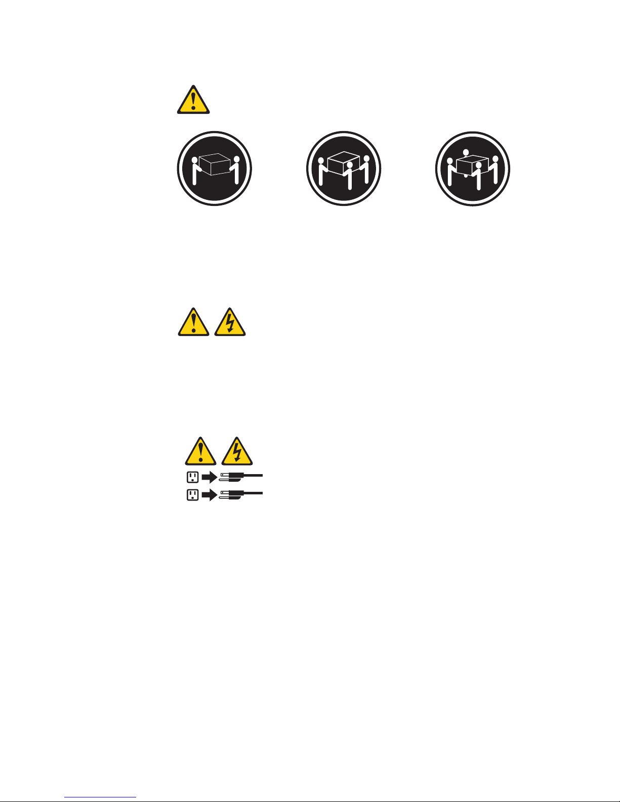
Statement 4:
≥ 18 kg (39.7 lb) ≥ 32 kg (70.5 lb) ≥ 55 kg (121.2 lb)
CAUTION:
Use safe practices when lifting.
Statement 5:
CAUTION:
The power control button on the device and the power switch on the power
supply do not turn off the electrical current supplied to the device. The device
also might have more than one power cord. To remove all electrical current
from the device, ensure that all power cords are disconnected from the power
source.
2
1
Safety ix
Page 12

Statement 8:
CAUTION:
Never remove the cover on a power supply or any part that has the following
label attached.
Hazardous voltage, current, and energy levels are present inside any
component that has this label attached. There are no serviceable parts inside
these components. If you suspect a problem with one of these parts, contact
a service technician.
Statement 26:
CAUTION:
Do not place any object on top of rack-mounted devices.
Statement 27:
CAUTION:
Hazardous moving parts are nearby.
x IBM System x3850 M2 and System x3950 M2 Types 7141 and 7233: User’s Guide
Page 13

Chapter 1. The System x3850 M2 and System x3950 M2 server
The IBM®System x3850 M2 and System x3950 M2 Types 7141 and 7233 servers
are 4-U
1
-high, high-performance servers. They are ideally suited for networking
environments that require superior microprocessor performance, efficient asset
management, flexibility, and large amounts of reliable data storage.
When they are available, you can purchase one or more SMP expansion kits to
interconnect System x3850 M2 and System x3950 M2 servers to create multi-node
configurations of two, three, or four nodes, for up to a 16-socket operation.
Performance, ease of use, reliability, and expansion capabilities were key
considerations in the design of the server. These design features make it possible
for you to customize the system hardware to meet your needs today and provide
flexible expansion capabilities for the future.
The server comes with a limited warranty. For information about the terms of the
warranty and getting service and assistance, see the Warranty Information
document.
®
The server contains IBM Enterprise X-Architecture
technologies, which help
increase performance and reliability. For more information, see “What your server
offers” on page 6 and “Reliability, availability, and serviceability” on page 8.
You can obtain up-to-date information about the server and other IBM server
products at http://www.ibm.com/systems/x/.
Related documentation
This User’s Guide contains general information about the server, including how to
install supported optional devices and how to configure the server. The following
documentation also comes with the server:
v Installation Guide
This printed document contains instructions for setting up the server and basic
instructions for installing some optional devices.
v Warranty Information
This printed document contains information about the terms of the warranty.
v Safety Information
This document is in PDF on the IBM Documentation CD. It contains translated
caution and danger statements. Each caution and danger statement that appears
in the documentation has a number that you can use to locate the corresponding
statement in your language in the Safety Information document.
v Rack Installation Instructions
This printed document contains instructions for installing the server in a rack.
v Problem Determination and Service Guide
This document is in PDF on the IBM Documentation CD. It contains information
to help you solve problems yourself, and it contains information for service
technicians.
1. Racks are measured in vertical increments of 4.45 cm (1.75 inches) each. Each increment is called a ″U.″ A 1-U-high device is
1.75 inches tall.
© Copyright IBM Corp. 2009
1
Page 14

v Environmental Notices and User Guide
This document is in PDF on the IBM Documentation CD. It contains translated
environmental notices.
v IBM License Agreement for Machine Code
This document is in PDF on the IBM Documentation CD. It provides translated
versions of the IBM License Agreement for Machine code for your product.
v IBM MCP Linux License Information and Attributions
This document is in PDF on the IBM Document CD. It provides information about
the open-source notices.
Depending on the server model, additional documentation might be included on the
IBM Documentation CD.
The System x and xSeries Tools Center is an online information center that
contains information about tools for updating, managing, and deploying firmware,
device drivers, and operating systems. The System x and xSeries Tools Center is at
http://publib.boulder.ibm.com/infocenter/toolsctr/v1r0/index.jsp.
The server might have features that are not described in the documentation that
comes with the server. The documentation might be updated occasionally to include
information about those features, or technical updates might be available to provide
additional information that is not included in the server documentation. These
updates are available from the IBM Web site. To check for updated documentation
and technical updates, complete the following steps.
Note: Changes are made periodically to the IBM Web site. The actual procedure
might vary slightly from what is described in this document.
1. Go to http://www.ibm.com/systems/support/.
2. Under Product support, click System x.
3. Under Popular links, click Publications lookup.
4. From the Product family menu, select System x3850 M2 or System x3950 M2
and click Continue.
Notices and statements in this document
The caution and danger statements in this document are also in the multilingual
Safety Information document, which is on the IBM Documentation CD. Each
statement is numbered for reference to the corresponding statement in your
language in the Safety Information document.
The following notices and statements are used in this document:
v Note: These notices provide important tips, guidance, or advice.
v Important: These notices provide information or advice that might help you avoid
inconvenient or problem situations.
v Attention: These notices indicate potential damage to programs, devices, or
data. An attention notice is placed just before the instruction or situation in which
damage might occur.
v Caution: These statements indicate situations that can be potentially hazardous
to you. A caution statement is placed just before the description of a potentially
hazardous procedure step or situation.
2 IBM System x3850 M2 and System x3950 M2 Types 7141 and 7233: User’s Guide
Page 15

v Danger: These statements indicate situations that can be potentially lethal or
extremely hazardous to you. A danger statement is placed just before the
description of a potentially lethal or extremely hazardous procedure step or
situation.
Chapter 1. The System x3850 M2 and System x3950 M2 server 3
Page 16

Features and specifications
The following information is a summary of the features and specifications of the
server. Depending on the server model, some features might not be available, or
some specifications might not apply.
Notes:
1. Racks are marked in vertical increments of 4.45 cm (1.75 inches). Each
increment is referred to as a unit, or “U.” A 1-U-high device is 4.45 cm (1.75
inches) tall.
2. Power consumption and heat output vary depending on the number and type of
optional features that are installed and the power-management optional features
that are in use.
3. These levels were measured in controlled acoustical environments according to
the procedures specified by the American National Standards Institute (ANSI)
S12.10 and ISO 7779 and are reported in accordance with ISO 9296. Actual
sound-pressure levels in a given location might exceed the average values
stated because of room reflections and other nearby noise sources. The
declared sound-power levels indicate an upper limit, below which a large
number of computers will operate.
4 IBM System x3850 M2 and System x3950 M2 Types 7141 and 7233: User’s Guide
Page 17

Table 1. Features and specifications
Microprocessor:
®
v Intel
v 1066 MHz front-side bus (FSB)
v Single node minimum: One
v Multi-node minimum: One
v Support for up to four microprocessors
Note: Use the Configuration/Setup Utility
program to determine the type and speed
of the microprocessors.
Memory:
v Single-node minimum: 2 GB depending
v Multi-node minimum: 4 GB in node 1
v Type: Registered, ECC, PC2-5300
v Sizes: 1 GB, 2 GB, 4 GB or 8 GB (when
v Connectors: Two-way interleaved, eight
v Maximum: Four memory cards, each
Drives:
v Slim DVD-ROM: IDE and SATA (optional
v Serial Attached SCSI (SAS) hard disk
Expansion bays:
v Four SAS, 2.5-inch bays
v One 12.7 mm removable-media drive
Expansion slots:
Seven PCI Express x8 (half-length) slots:
v Five non-hot-swap
v Two hot-swap
Xeon®multi-core microprocessor
with 8 MB Level-2 cache
microprocessor per core
microprocessor per core in each node
on server model, expandable to 256 GB
and 2 GB in all other modes expandable
to a total of 1 TB
double data rate (DDR) II, SDRAM
available) in pairs
dual inline memory module (DIMM)
connectors per memory card
card containing four pairs of PC2-5300
DDR II DIMMs
in some models)
drives
bay (DVD drive installed, standard on
some models only)
Upgradeable microcode:
System BIOS, FPGA, diagnostics, service
processor, BMC, and SAS microcode
Power supply:
v Standard: One or two dual-rated power
supplies, depending on the model
– 1440 watts at 220 V ac input
– 720 watts at 110 V ac input
v Hot-swappable and redundant at 220 V
ac, only with two power supplies
v If the server is operating at 110 V ac, a
second power supply must be installed
to maintain a fully functional server.
Size:
v 4U
v Height: 128.35 mm (5.05 in.)
v Depth: 715 mm (28.15 in.)
v Width: 440 mm (17.32 in.)
v Weight: approximately 43.1 kg (95 lb)
when fully configured or 31.75 kg (70
lb) minimum
Integrated functions:
v Baseboard management controller
v IBM EXA-4 chip set with integrated
memory and I/O controller
v Remote Supervisor Adapter II
v Light path diagnostics
v Six Universal Serial Bus (USB) ports
(2.0)
– Three on rear of server
– Two on front of server
– One internal
v Broadcom 5709 dual 10/100/1000
Gigabit Ethernet controller
v ATI RN50 video
– 16 MB video memory
– SVGA compatible
v Serial-attached SCSI (SAS) controller
with RAID capabilities
v Support for ServeRAID-MR10k SAS
controller
v Serial connector
v SMP Expansion Ports
Acoustical noise emissions:
v Sound power, idle: 6.6 bel declared
v Sound power, operating: 6.6 bel
declared
Environment:
v Air temperature:
– Server on:
- 10° to 35°C (50° to 95°F); altitude:
0 to 914 m (3000 ft). If the server
has a dual-core microprocessor, at
maximum power reduce the 35°C
by 1°C per 300 m above sea level,
or the microprocessor might throttle
to remain within the internal thermal
specifications.
- 10° to 32°C (50° to 90°F); altitude:
914 m to 2133 m (7000 ft).
– Server off: 10° to 43°C (50.0° to
109.4°F); maximum altitude: 2133 m
(6998.0 ft)
v Humidity:
– Server on: 8% to 80%
– Server off: 8% to 80%
v Particulate contamination:
Attention: Airborne particulates and
reactive gases acting alone or in
combination with other environmental
factors such as humidity or temperature
might pose a risk to the server. For
information about the limits for
particulates and gases, see “Particulate
contamination” on page 81.
Heat output:
Approximate heat output:
v Minimum configuration: 1297 Btu (380
watts) per hour
v Typical configuration: 2730 Btu (800
watts) per hour
v Maximum configuration:
– 5527 Btu per hour (1620 watts) at 110
Vac
– 5425 Btu per hour (1590 watts) at 220
Vac
Electrical input:
v Sine-wave input (50 - 60 Hz) required
v Input voltage low range:
– Minimum: 100 V ac
– Maximum: 127 V ac
v Input voltage high range:
– Minimum: 200 V ac
– Maximum: 240 V ac
v Approximate input kilovolt-amperes (kVA):
– Minimum: 0.39 kVA
– Typical: 0.8 kVA
– Maximum: 1.65 kVA
Chapter 1. The System x3850 M2 and System x3950 M2 server
5
Page 18

What your server offers
The server uses the following features and technologies:
v Baseboard management controller
The baseboard management controller (BMC) provides basic service-processor
environmental monitoring functions. If an environmental condition exceeds a
threshold or if a system component fails, the baseboard management controller
lights LEDs to help you diagnose the problem and records the error in the error
log. The baseboard management controller also provides remote server
management capabilities through the OSA SMBridge management utility
program.
Note: In messages and documentation, the term service processor refers to the
baseboard management controller or the Remote Supervisor Adapter II.
v IBM Director
IBM Director is a workgroup-hardware-management tool that you can use to
centrally manage IBM System x and xSeries
the IBM Director documentation on the IBM Director CD.
v IBM Electronic Service Agent
IBM Electronic Service Agent is a software tool that monitors the server for
hardware error events and automatically submits electronic service requests to
the IBM Support Center. Also, it can collect and transmit system configuration
information on a scheduled basis so that the information is available to you and
your support representative. It uses minimal system resources, is available free
of charge, and can be downloaded from the Web. For more information and to
download Electronic Service Agent, go to http://www.ibm.com/support/electronic/.
v IBM Enterprise X-Architecture technology
IBM X-Architecture technology combines proven, innovative IBM designs to make
your x86-processor-based server powerful, scalable, and reliable. For more
information, see http://www.ibm.com/servers/eserver/xseries/xarchitecture/
enterprise/index.html.
– Active
The Active Memory feature improves the reliability of memory through
online-spare memory, memory mirroring, and memory scrubbing. Online-spare
memory disables a failed pair of DIMMs from the server configuration and
activates a pair of online-spare DIMMs. Memory scrubbing is an automatic
daily test of all the system memory that detects and reports memory errors
that might develop, before they cause a server outage.
– Large system-memory capacity
The server supports up to 256 GB of system memory. The memory controller
supports error correcting code (ECC) for up to 32 industry-standard
PC2-5300, 1.8 V, 240-pin, registered, double-data-rate (DDR) II, synchronous
dynamic random access memory (SDRAM) dual inline memory modules
(DIMMs).
– Memory ProteXion
The Memory ProteXion feature provides the equivalent of a hot-spare drive in
a RAID array. It is based in the memory controller, and it enables the server to
sense when a chip on a DIMM has failed and to route the data around the
failed chip.
v IBM ServerGuide Setup and Installation CD
The ServerGuide Setup and Installation CD that comes with the server provides
programs to help you set up the server and install a Windows operating system.
™
Memory
®
servers. For more information, see
6 IBM System x3850 M2 and System x3950 M2 Types 7141 and 7233: User’s Guide
Page 19

The ServerGuide program detects installed optional hardware devices and
provides the correct configuration programs and device drivers. For more
information about the ServerGuide Setup and Installation CD, see “Using the
ServerGuide Setup and Installation CD” on page 68.
v Integrated network support
The server comes with an integrated Broadcom 5709 dual Gigabit Ethernet
controller, which supports connection to a 10 Mbps, 100 Mbps, or 1000 Mbps
network. For more information, see “Configuring the Gigabit Ethernet controller”
on page 70.
v Integrated Trusted Platform Module (TPM)
This integrated security chip performs cryptographic functions and stores private
and public secure keys. It provides the hardware support for the Trusted
Computing Group (TCG) specification. You can download the software to support
the TCG specification, when the software is available. See http://www.ibm.com/
servers/eserver/xseries/scalable_family.html for details about the TPM
implementation.
v Large data-storage capacity and hot-swap capability
The server supports up to four 1-inch (26 mm) slim-high, 2.5-inch hot-swap hard
disk drives that are connected to the SAS backplane. With the hot-swap feature,
you can add, remove, or replace hard disk drives without turning off the server.
v Light path diagnostics
Light path diagnostics provides LEDs to help you diagnose problems. For more
information, see the section about light path diagnostics in the Problem
Determination and Service Guide.
v PCI Express x8 adapter capabilities
The server has seven slots for PCI Express x8 adapters. These slots also accept
x4 adapters.
v Active Energy Manager
The IBM Active Energy Manager solution is an IBM Director extension that
measures and reports server power consumption as it occurs. This enables you
to monitor power consumption in correlation to specific software application
programs and hardware configurations. You can obtain the measurement values
through the systems-management interface and view them, using IBM Director.
For more information, including the required levels of IBM Director and Active
Energy Manager, see the IBM Director documentation on the IBM Director CD, or
go to http://www.ibm.com/servers/eserver/xseries/systems_management/
ibm_director /extensions/.
v Dynamic System Analysis (DSA) Preboot diagnostic programs
The DSA Preboot diagnostic programs are stored in integrated USB memory and
collect and analyze system information to aid in diagnosing server problems. The
diagnostic programs collect the following information about the server:
– System configuration
– Network interfaces and settings
– Installed hardware
– Light path diagnostics status
– Service processor status and configuration
– Vital product data, firmware, and BIOS configuration
– Hard disk drive health
– RAID controller configuration
– Event logs for ServeRAID controllers and service processors
The diagnostic programs create a merged log that includes events from all
collected logs. The information is collected into a file that you can send to the
Chapter 1. The System x3850 M2 and System x3950 M2 server 7
Page 20

IBM Support Center. Additionally, you can view the server information locally
through a generated text report file. You can also copy the log to removable
media and view the log from a Web browser.
v Redundant connection
The addition of an optional network interface card (NIC) provides a failover
capability to a redundant Ethernet connection. If a problem occurs with the
primary Ethernet connection, all Ethernet traffic that is associated with the
primary connection is automatically switched to the redundant NIC. If the
applicable device drivers are installed, this switching occurs without data loss and
without user intervention.
v Redundant cooling and power capabilities
The redundant cooling of the fans in the server enable continued operation if one
of the fans fails. The server supports up to two hot-swap power supplies, which
provide redundant power for many server configurations.
v ServeRAID support
The server supports ServeRAID controllers to create redundant array of
independent disks (RAID) configurations.
v Symmetric multiprocessing (SMP)
The server supports up to four multi-core Intel Xeon microprocessors. One or
more multi-core microprocessors provides SMP capability.
v Systems-management capabilities
The server supports an IBM Remote Supervisor Adapter II. When this adapter is
used with the systems-management software that comes with the server, you can
manage the functions of the server locally and remotely. The Remote Supervisor
Adapter II also provides system monitoring, event recording, and dial-out alert
capability.
Reliability, availability, and serviceability
Three important server design features are reliability, availability, and serviceability
(RAS). The RAS features help to ensure the integrity of the data that is stored in
the server, the availability of the server when you need it, and the ease with which
you can diagnose and correct problems.
The server has the following RAS features:
v Active memory
v Automatic BIOS recovery (ABR)
v Automatic error retry and recovery
v Automatic restart after a power failure
v Availability of microcode and diagnostic levels
v Backup basic input/output system (BIOS) switching under the control of the
service processor
v Baseboard management controller (service processor)
v Built-in, menu-driven electrically erasable programmable ROM (EEPROM) based
setup, system configuration, and diagnostic programs
v Built-in monitoring for fan, power, temperature, voltage, and power-supply
redundancy
v Error codes and messages
v Error correcting code (ECC) L2 cache and system memory
v Fault-resistant startup
v Hot-swap hard disk drives
v IBM Director workgroup-hardware-management tool
v Information and light path diagnostics LED panels
8 IBM System x3850 M2 and System x3950 M2 Types 7141 and 7233: User’s Guide
Page 21

v Service processor adapter for remote systems management
v Parity checking on the SAS bus and PCI Express buses
v Power managed and Advanced Configuration and Power Interface (ACPI)
compliant
v Power-on self-test (POST)
v Predictive Failure Analysis (PFA) alerts
v Redundant Ethernet capabilities (requires optional Ethernet adapter) with failover
support
v Redundant hot-swap capability
– Cooling fans with speed-sensing capability
– Power supplies
v Remind button to temporarily flash the system-error LED
v Remote system problem-determination support
v ROM-based diagnostic programs
v Standby voltage for systems-management features and monitoring
v Startup (boot) from LAN using Preboot Execution Environment (PXE) protocol
v System auto-configuring from the configuration menu
v System error logging
v Upgradeable microcode for POST, BIOS, diagnostics, service processor, and
read-only memory (ROM) resident code, locally or over the LAN
v Vital product data (VPD) on microprocessors, system boards, power supplies,
and SAS (hot-swap-drive) backplane
v Wake on LAN capability
IBM Director
With IBM Director, a network administrator can perform the following tasks:
v View the hardware configuration of remote systems, in detail
v Monitor the usage and performance of critical components, such as
microprocessors, disks, and memory
v Centrally manage individual or large groups of IBM and non-IBM
x86-processor-based servers, desktop computers, workstations, and notebook
computers on a variety of platforms
IBM Director provides a comprehensive entry-level workgroup hardware manager. It
includes the following key features:
v Advanced self-management capabilities for maximum system availability.
®
v Multiple operating-system platform support, including Microsoft
Windows®2000
Server, Windows Server 2003, Windows XP Professional, AIX, i5/OS, Red Hat
Linux, SUSE Linux, VMware, and Novell NetWare. For a complete list of
operating systems that support IBM Director, see the IBM Director Compatibility
Document. This document is in Portable Document Format (PDF) at
http://www.ibm.com/systems/management/director/resources/. It is updated every
6 to 8 weeks.
v Support for IBM and non-IBM servers, desktop computers, workstations, and
notebook computers.
v Support for systems-management industry standards.
v Integration into leading workgroup and enterprise systems-management
environments.
v Ease of use, training, and setup.
IBM Director also provides an extensible platform that supports advanced server
tools that are designed to reduce the total cost of managing and supporting
Chapter 1. The System x3850 M2 and System x3950 M2 server 9
Page 22

networked systems. By deploying IBM Director, you can achieve reductions in
ownership costs through the following benefits:
v Reduced downtime
v Increased productivity of IT personnel and users
v Reduced service and support costs
For more information about IBM Director, see the documentation on the IBM
Director CD that comes with the server, the IBM Director Information Center at
http://publib.boulder.ibm.com/infocenter/eserver/v1r2/topic/diricinfo_all/
diricinfoparent.html, and the IBM System x and xSeries Systems Management Web
page at http://www.ibm.com/systems/management/, which presents an overview of
IBM Systems Management and IBM Director.
The UpdateXpress program
The UpdateXpress program is available for most System x and xSeries servers and
optional devices. It detects supported and installed device drivers and firmware in
the server and installs available updates. You can download the UpdateXpress
program from the Web at no additional cost, or you can purchase it on a CD. To
download the program or purchase the CD, go to http://www.ibm.com/systems/
management/xpress.html. Additional information about UpdateXpress is available
from the System x and xSeries Tools Center at http://publib.boulder.ibm.com/
infocenter/toolsctr/v1r0/index.jsp.
10 IBM System x3850 M2 and System x3950 M2 Types 7141 and 7233: User’s Guide
Page 23
Server controls, connectors, LEDs, and power
This section describes the controls, connectors, and light-emitting diodes (LEDs)
and how to turn the server on and off.
Front view
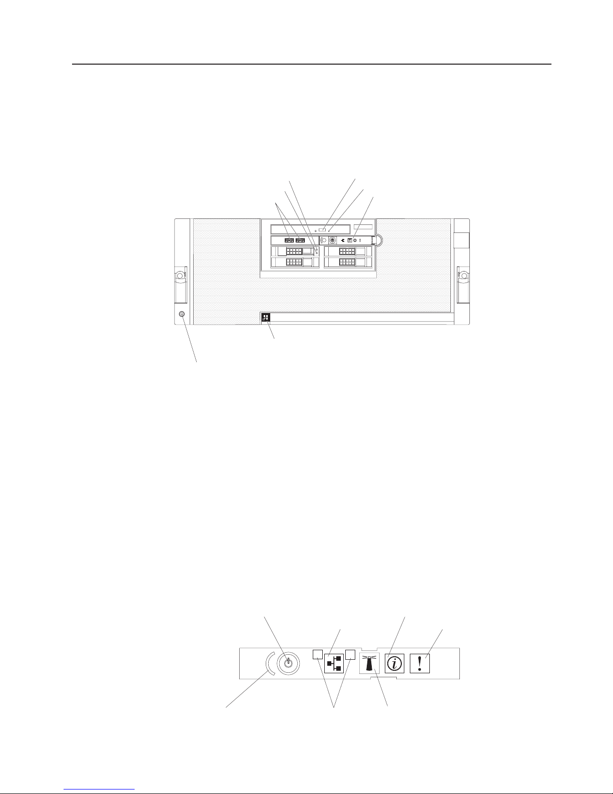
The following illustration shows the controls, LEDs, and connectors on the front of
the server.
Hard disk drive activity LED
Hard disk drive status LED
USB connectors
Scalability LED
Electrostatic-discharge connector
Hard disk drive activity LED: On some server models, each hot-swap hard disk
drive has an activity LED. When this LED is flashing, it indicates that the drive is in
use.
DVD-eject button
DVD drive activity LED
12
3
4
Operator information panel
Hard disk drive status LED: On some server models, each hot-swap hard disk
drive has a status LED. When this LED is lit continuously, that individual drive is
faulty. When the drive is connected to the integrated SAS controller with RAID
capabilities, a flashing status LED indicates that the drive is a secondary drive in a
mirrored pair and the drive is being synchronized.
USB connectors: Connect USB devices to these connectors.
DVD-eject button: Press this button to release a CD or DVD from the DVD drive.
DVD drive activity LED: When this LED is lit, it indicates that the DVD drive is in
use.
Operator information panel: This panel contains controls and LEDs. The following
illustration shows the controls and LEDs on the operator information panel.
Power-control button/power-on LED
Power-control button cover
Ethernet icon LED
1
Ethernet port activity LEDs
2
Information LED
System-error LED
Locator button/locator LED
The following controls and LEDs are on the operator information panel:
Chapter 1. The System x3850 M2 and System x3950 M2 server 11
Page 24

v Power-control button cover: Slide this cover over the power-control button to
prevent the server from being turned off accidentally.
v Power-control button: Press this button to turn the server on and off manually.
v Power-on LED: When this LED is lit and not flashing, it indicates that the server
is turned on. When this LED is flashing, it indicates that the server is turned off
and still connected to an ac power source. When this LED is off, it indicates that
ac power is not present or the power supply or the LED itself has failed.
Note: If this LED is off, it does not mean that there is no electrical power in the
server. The LED might be burned out. To remove all electrical power from the
server, you must disconnect the power cords from the electrical outlets.
v Ethernet-icon LED: This LED lights the Ethernet icon.
v Ethernet activity LEDs: When these LEDs flash, they indicate that there is
activity between the server and the network on the indicated port.
v Locator LED: Use this LED to visually locate the server among other servers.
You can use IBM Director to light this LED remotely or press the locator button to
light the LED manually. This LED is also lit during startup.
In multi-node configurations, when this LED flashes, it indicates that the server is
the primary node. When this LED is lit continuously, it indicates that the server is
a secondary node.
v Locator button: Press this button to turn the locator LED on and off manually. In
multi-node configurations, press this button to turn the locator LED on and off in
all nodes in the configuration.
v Information LED: When this LED is lit, it indicates that there is a suboptimal
condition in the server and that light path diagnostics will light an additional LED
to help isolate the condition. This LED and LEDs on the light path diagnostics
panel remain lit until you resolve the condition or you press the remind button.
v System-error LED: When this LED is lit, it indicates that a system error has
occurred. An LED on the light path diagnostics panel is also lit to help isolate the
error.
Electrostatic-discharge connector: Connect an electrostatic-discharge wrist strap
to this connector.
Scalability LED: When this LED is lit, it indicates that an optional scalability key is
installed in the server, which enables support for connecting the server to other
servers to form multi-node configurations.
12 IBM System x3850 M2 and System x3950 M2 Types 7141 and 7233: User’s Guide
Page 25
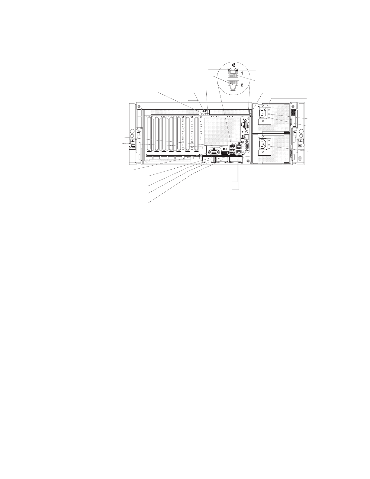
Rear view
The following illustration shows the connectors and LEDs on the rear of the server.
Power-on LED Locator LED
USB
SAS
System serial
SMP Expansion Port 1
link LED
SMP Expansion Port 1
SMP Expansion Port 2
link LED
SMP Expansion Port 2
Gigabit
Ethernet 2 LED
Gigabit Ethernet 2
System-error LED
SMP Expansion Port 3
SMP Expansion Port 3
link LED
Gigabit
Ethernet 1 LED
Gigabit Ethernet 1
Remote Supervisor Adapter II
Power
supply 1
AC power
DC power
Power-
supply error
Power
supply 2
Power-on LED: When this LED is lit and not flashing, it indicates that the server is
turned on. When this LED is flashing, it indicates that the server is turned off and
still connected to an ac power source. When this LED is off, it indicates that ac
power is not present or the power supply or the LED itself has failed.
Note: If this LED is off, it does not mean that there is no electrical power in the
server. The LED might be burned out. To remove all electrical power from the
server, you must disconnect the power cords from the electrical outlets.
Locator LED: Use this LED to visually locate the server among other servers. You
can use IBM Director to light this LED remotely or press the locator button to light
the LED manually. This LED is also lit during startup.
System-error LED: When this LED is lit, it indicates that a system error has
occurred. An LED on the light path diagnostics panel is also lit to help isolate the
error.
Gigabit Ethernet 2 LED: When this LED flashes, it indicates that there is activity
between the server and the network. When this LED is lit continuously, it indicates
that there is an active connection on the Ethernet port.
Gigabit Ethernet 2 connector: Use this connector to connect the server to a
network.
Gigabit Ethernet 1 LED: When this LED flashes, it indicates that there is activity
between the server and the network. When this LED is lit continuously, it indicates
that there is an active connection on the Ethernet port.
Gigabit Ethernet 1 connector: Use this connector to connect the server to a
network. This connector is shared with the baseboard management controller
Chapter 1. The System x3850 M2 and System x3950 M2 server 13
Page 26

(BMC) and is assigned two MAC addresses. For information about configuring the
controller, see the Broadcom NetXtreme Gigabit Ethernet Software CD that comes
with the server.
Remote Supervisor Adapter II controls, connectors, and LEDs: These controls,
connectors, and LEDs are used for system management information and control.
Adapter activity LED
Power LED
Reset button (recessed)
ASM connector
Mini-USB connector
External power
supply connector
Ethernet connector
(RJ-45)
Video connector
The following controls, connectors, and LEDs are on the Remote Supervisor
Adapter II:
v Adapter activity LED: When this LED is flashing, the Remote Supervisor
Adapter II is functioning normally. When this LED is lit continuously, there is a
problem with the Remote Supervisor Adapter II. When the LED is off, the Remote
Supervisor Adapter II is not functioning.
v Power LED: When this LED is lit, the Remote Supervisor Adapter II is receiving
power from the server, or from an external power-supply.
v Reset button: (Trained service technician only) Insert and press the open end of
a paper clip (or similar object) into the recessed reset button to manually reset
the Remote Supervisor Adapter II.
v Mini-USB connector: This connector is not supported.
v Video connector: Use this connector to connect the server monitor.
v Ethernet connector (RJ45): Use this connector to connect a Category 3 (10
Mbps) or Category 5 (100 Mbps) Ethernet cable to enable a LAN connection.
v External power-supply connector: Use this connector to connect an external
power-supply to the Remote Supervisor Adapter II.
v ASM connector: This connector is not supported.
Power supply 1 connector: Connect the power cord to this connector.
14 IBM System x3850 M2 and System x3950 M2 Types 7141 and 7233: User’s Guide
Page 27

AC power LED: This green LED provides status information about the power
supply. During typical operation, both the ac and dc power LEDs are lit. For any
other combination of LEDs, see the Problem Determination and Service Guide on
the IBM System x Documentation CD.
DC power LED: This green LED provides status information about the power
supply. During typical operation, both the ac and dc power LEDs are lit. For any
other combination of LEDs, see the Problem Determination and Service Guide on
the IBM System x Documentation CD.
Power-supply error LED: When this amber LED is lit, it indicates that there is an
error condition within the power supply. For more information, see the Problem
Determination and Service Guide on the IBM System x Documentation CD.
Power supply 2 connector: Connect the power cord to this connector.
SMP Expansion Port 3 connector: Use this connector to connect the server to
other servers to form multi-node configurations (requires scalability enablement).
SMP Expansion Port 3 link LED: When this LED is lit, it indicates that there is an
active connection on SMP Expansion Port 3.
SMP Expansion Port 1 link LED: When this LED is lit, it indicates that there is an
active connection on SMP Expansion Port 1.
SMP Expansion Port 1 connector: Use this connector to connect the server to
other servers to form multi-node configurations (requires scalability enablement).
SMP Expansion Port 2 link LED: When this LED is lit, it indicates that there is an
active connection on SMP Expansion Port 2.
SMP Expansion Port 2 connector: Use this connector to connect the server to
other servers to form multi-node configurations (requires scalability enablement).
System serial connector: Connect a 9-pin serial device to this connector.
SAS connector: Connect an internal SAS device to this connector.
USB connectors: Connect USB devices to these connectors.
Server power features
When the server is connected to an ac power source but is not turned on, the
operating system does not run, and all core logic except for the service processor is
shut down; however, the server can respond to requests from the service processor,
such as a remote request to turn on the server. The power-on LED flashes to
indicate that the server is connected to ac power but not turned on.
Turning on the server
Approximately 20 seconds after the server is connected to ac power, the
power-control button becomes active, and one or more fans might start running to
provide cooling while the server is connected to power. You can turn on the server
and start the operating system by pressing the power-control button.
The server can also be turned on in any of the following ways:
Chapter 1. The System x3850 M2 and System x3950 M2 server 15
Page 28
v If a power failure occurs while the server is turned on, the server will restart
automatically when power is restored.
v If the server is installed in a static partition, you can turn on the server and start
the operating system by pressing the power-control button on the primary node in
the partition.
v If your operating system supports the systems-management software for the
Remote Supervisor Adapter II, the systems-management software can turn on
the server.
v If your operating system supports the Wake on LAN feature, the Wake on LAN
feature can turn on the server.
Note: When 4 GB or more of memory (physical or logical) is installed, some
memory is reserved for various system resources and might be unavailable to the
operating system. The amount of memory that is reserved for system resources
depends on the operating system, the configuration of the server, and the
configured PCI options.
Turning off the server
When you turn off the server and leave it connected to ac power, the server can
respond to requests from the service processor, such as a remote request to turn
on the server. While the server remains connected to ac power, one or more fans
might continue to run. To remove all power from the server, you must disconnect it
from the power source.
Some operating systems require an orderly shutdown before you turn off the server.
See your operating-system documentation for information about shutting down the
operating system.
Statement 5:
CAUTION:
The power control button on the device and the power switch on the power
supply do not turn off the electrical current supplied to the device. The device
also might have more than one power cord. To remove all electrical current
from the device, ensure that all power cords are disconnected from the power
source.
2
1
The server can be turned off in any of the following ways:
v You can turn off the server from the operating system, if your operating system
supports this feature. After an orderly shutdown of the operating system, the
server will be turned off automatically.
v You can press the power-control button to start an orderly shutdown of the
operating system and turn off the server, if your operating system supports this
feature.
16 IBM System x3850 M2 and System x3950 M2 Types 7141 and 7233: User’s Guide
Page 29

v If the operating system stops functioning, you can press and hold the
power-control button for more than 4 seconds to turn off the server.
v If the server is installed in a static partition, pressing the power-control button on
the primary node in the partition will start an orderly shutdown of the operating
system and turn off the server.
v The server can be turned off from the Remote Supervisor Adapter II user
interface.
v If the Wake on LAN feature turned on the server, the Wake on LAN feature can
turn off the server.
v You can turn off the server through a request from the service processor.
Chapter 1. The System x3850 M2 and System x3950 M2 server 17
Page 30

18 IBM System x3850 M2 and System x3950 M2 Types 7141 and 7233: User’s Guide
Page 31

Chapter 2. Installing optional devices
This chapter provides detailed instructions for installing optional hardware devices in
the server.
Server components
The following illustrations show the major components in the server. The
illustrations in this document might differ slightly from your hardware.
© Copyright IBM Corp. 2009 19
Page 32

continued
Remote Supervisor Adapter II
PCI divider
with battery holder
ServeRAID-MR10k
controller
Hot-swap power supply
Top cover
Adapter-retention
bracket
PCI divider
PCI switch-card
assembly
I/O board shuttle assembly
20 IBM System x3850 M2 and System x3950 M2 Types 7141 and 7233: User’s Guide
Page 33

Memory-card DIMM connectors
The following illustration shows the DIMM connectors on the memory card.
Memory-card LEDs
The following illustration shows the LEDs on the memory card.
DIMM 1
DIMM 2
DIMM 3
DIMM 4
DIMM 5
DIMM 6
DIMM 7
DIMM 8
Memory hot-swap enabled LED
Memory-card/DIMM error LED
Memory-card power LED
Memory-card only error LED
Light path diagnostics button
Light path diagnostics button power LED
Visible from top of
memory card
DIMM 1 error LED
DIMM 2 error LED
DIMM 3 error LED
DIMM 4 error LED
DIMM 5 error LED
DIMM 6 error LED
DIMM 7 error LED
DIMM 8 error LED
Chapter 2. Installing optional devices 21
Page 34

Microprocessor-board connectors
The following illustration shows the connectors on the microprocessor board.
Power backplane
Scalability I/O board
Fan 5
Fan 4
Fan 2
Fan 1
Microprocessor 3
VRM 3
Microprocessor 1
Memory card 1
Memory card 2
VRM 1
Fan 6
Fan 3
Microprocessor 4
3
1
2
Scalability key
4
VRM 4
Microprocessor 2
Memory card 4
Memory card 3
VRM 2
22 IBM System x3850 M2 and System x3950 M2 Types 7141 and 7233: User’s Guide
Page 35

Microprocessor-board LEDs
The following illustration shows the LEDs on the microprocessor board.
FPGA heartbeat
LED
Board
fault LED
Microprocessor 3
error LED
VRM 3 error LED
Microprocessor 1
error LED
VRM 1 error LED
3
1
Power good LED
Scalability enabled LED
2
Machine check LED
4
BMC heartbeat
LED
Microprocessor 4
error LED
VRM 4 error LED
Microprocessor 2
error LED
VRM 2 error LED
Table 2 describes the function of each status LED other than light path diagnostics
LEDs.
Table 2. Microprocessor-board status LEDs (other than light path diagnostics)
LED Description
BMC heartbeat When this LED is flashing, it indicates normal operation of the
baseboard management controller.
FPGA heartbeat When this LED is flashing, it indicates normal operation of the FPGA
(field-programmable gate array) chip.
Machine check When this LED is lit continuously, the server is prepared to capture a
machine check. When this LED is flashing, the server has captured
a machine check. When this LED is off, the server is not prepared to
capture a machine check.
Chapter 2. Installing optional devices 23
Page 36

Microprocessor-board jumpers
The following illustration shows the jumpers on the microprocessor board.
3
1 2
Force BMC
update
(J57)
321
Physical
presence
(J70)
4
1
2
3
2
Boot recovery (J17)
1
Table 3 describes the function of each jumper block.
Table 3. Microprocessor-board jumper blocks
Jumper name Description
Boot recovery (BIOS) (J17) The default position is pins 1 and 2 (use the primary page during
startup). Move the jumper to pins 2 and 3 to use the secondary
page during startup.
Force BMC update (J57) Place a jumper over pins 1 and 2 to bypass the operational firmware
image and perform a baseboard management controller firmware
update, if the operational image is corrupted.
Note: Only use the force BMC update jumper if the normal firmware
update procedure fails and the operational firmware image is
corrupted. Use of the force BMC update jumper disables normal
baseboard management controller operation.
24 IBM System x3850 M2 and System x3950 M2 Types 7141 and 7233: User’s Guide
Page 37

I/O-board connectors
The following illustration shows the connectors on the I/O board.
SAS
backplane
signal
Remote
Supervisor
Adapter II
System
Management
access
Battery
Front USB
SATA signal
If you are installing a hypervisor key, install it in the internal USB connector.
Remote Supervisor Adapter II
Internal USB
ServeRAID-MR10k
SATA power
SAS backplane power
Front panel/light path diagnostics
DVD
Hot-plug switch card
PCI Express x8
(x8 lanes) slot 1
PCI Express x8
(x8 lanes) slot 2
PCI Express x8
(x8 lanes) slot 3
PCI Express x8
(x8 lanes) slot 4
PCI Express x8
(x8 lanes) slot 5
PCI Express x8
(x8 lanes) slot 6
PCI Express x8
(x8 lanes) slot 7
I/O-board LEDs
The following illustration shows the LEDs on the I/O board.
I/O card
fault LED
RAID write
protect LED
SAS
heartbeat LED
ServeRAID-MR10k
fault LED
Power LED (2x)
Attention LED (7x)
Chapter 2. Installing optional devices 25
Page 38

I/O-board jumpers
The following illustration shows the jumpers on the I/O board.
Power-on
password
(J33)
1
2
3
1
2
3
Wake on LAN
bypass (J38)
1
2
Force power-on (J32)
3
Table 4 describes the function of each jumper block.
Table 4. I/O board jumper blocks
Jumper name Description
Force power-on (J32) The default position is pins 1 and 2. Change the position of this
jumper to pins 2 and 3 to force the server to start when you connect
the server to ac power.
Note: Use the force power-on jumper only for diagnosing power
problems. POST might not be completed, and the server might not
start.
Power-on password (J33) The default position is pins 1 and 2. Change the position of this
jumper to pins 2 and 3 to bypass the power-on password check.
Changing the position of this jumper does not affect the
administrator password check if an administrator password is set. If
the administrator password is lost, the microprocessor board must
be replaced.
For more information about passwords, see “Passwords” on page
66.
Wake on LAN bypass (J38) The default position is pins 1 and 2. Move the jumper to pins 2 and
26 IBM System x3850 M2 and System x3950 M2 Types 7141 and 7233: User’s Guide
3 to prevent a Wake on LAN packet from waking the system when
the system is in the powered-off state.
Page 39

SAS-backplane connectors
The following illustration shows the connectors on the SAS backplane.
SAS signal connector
SAS power connector
SAS hard disk drive
connectors
Chapter 2. Installing optional devices 27
Page 40

Installation guidelines
Before you install optional devices, read the following information:
v Read the safety information that begins on page v, the guidelines in “Working
inside the server with the power on” on page 29, and “Handling static-sensitive
devices” on page 30. This information will help you work safely.
v When you install your new server, take the opportunity to download and apply
the most recent firmware updates. This step will help to ensure that any known
issues are addressed and that your server is ready to function at maximum levels
of performance. To download firmware updates for your server, complete the
following steps.
Note: Changes are made periodically to the IBM Web site. The actual procedure
might vary slightly from what is described in this document.
1. Go to http://www.ibm.com/systems/support/.
2. Under Product support, click System x.
3. Under Popular links, click Software and device drivers.
4. Click IBM System x3850 M2 or IBM System x3950 M2 to display the matrix
of downloadable files for the server.
For additional information about tools for updating, managing, and deploying
firmware, see the System x and xSeries Tools Center at http://
publib.boulder.ibm.com/infocenter/toolsctr/v1r0/index.jsp.
v Before you install optional hardware devices, make sure that the server is
working correctly. Start the server, and make sure that the operating system
starts, if an operating system is installed, or that a 19990305 error code is
displayed, indicating that an operating system was not found but the server is
otherwise working correctly. If the server is not working correctly, see “Solving
Problems” in the Installation Guide for diagnostic information.
v Observe good housekeeping in the area where you are working. Place removed
covers and other parts in a safe place.
v If you must start the server while the cover is removed, make sure that no one is
near the server and that no tools or other objects have been left inside the
server.
v Do not attempt to lift an object that you think is too heavy for you. If you have to
lift a heavy object, observe the following precautions:
– Make sure that you can stand safely without slipping.
– Distribute the weight of the object equally between your feet.
– Use a slow lifting force. Never move suddenly or twist when you lift a heavy
object.
– To avoid straining the muscles in your back, lift by standing or by pushing up
with your leg muscles.
v Make sure that you have an adequate number of properly grounded electrical
outlets for the server, monitor, and other devices.
v Back up all important data before you make changes to disk drives.
v Have a small flat-blade screwdriver available.
v You do not have to turn off the server to install or replace hot-swap power
supplies, hot-swap fans, hot-plug adapters, or hot-plug Universal Serial Bus
(USB) devices. However, you must turn off the server before you perform any
steps that involve removing or installing adapter cables.
v Blue on a component indicates touch points, where you can grip the component
to remove it from or install it in the server, open or close a latch, and so on.
28 IBM System x3850 M2 and System x3950 M2 Types 7141 and 7233: User’s Guide
Page 41

v Orange on a component or an orange label on or near a component indicates
that the component can be hot-swapped, which means that if the server and
operating system support hot-swap capability, you can remove or install the
component while the server is running. (Orange can also indicate touch points on
hot-swap components.) See the instructions for removing or installing a specific
hot-swap component for any additional procedures that you might have to
perform before you remove or install the component.
v When you are finished working on the server, reinstall all safety shields, guards,
labels, and ground wires.
v For a list of supported optional devices for the server, see http://www.ibm.com/
servers/eserver/serverproven/compat/us/.
Limitations in a single-power-supply server operating at 110 V ac
installation
If your server has only one power supply operating at 110 V ac, it will not support
some optional devices. In a single-power-supply server operating at 110 V ac the
following resources are supported:
v Up to two 2.66 GHz microprocessors or up to four slower microprocessors
v Sixteen DIMMs
v Three PCI expansion slots, if you do not install a video adapter or other high
powered PCI devices
System reliability guidelines
To help ensure proper system cooling and system reliability, make sure that the
following requirements are met:
v Each of the drive bays has a drive or a filler panel and electromagnetic
compatibility (EMC) shield installed in it.
v There is adequate space around the server to allow the server cooling system to
work properly. Leave approximately 50 mm (2 in.) of open space around the front
and rear of the server. Do not place objects in front of the fans. For proper
cooling and airflow, replace the server cover before you turn on the server.
Operating the server for extended periods of time (more than 30 minutes) with
the server cover removed might damage server components.
v You have followed the cabling instructions that come with optional adapters.
v You have replaced a failed fan as soon as possible.
v You have replaced a hot-swap drive within 2 minutes of removal.
v For redundant and hot-swappable power supply operation, the power supplies
are connected to 200-240 V ac.
v Microprocessor socket 2 always contains either a heat-sink blank or a
microprocessor and heat sink.
Working inside the server with the power on
Attention: Static electricity that is released to internal server components when
the server is powered-on might cause the server to halt, which might result in the
loss of data. To avoid this potential problem, always use an electrostatic-discharge
wrist strap or other grounding system when you work inside the server with the
power on.
The server supports hot-plug, hot-add, and hot-swap devices and is designed to
operate safely while it is turned on and the cover is removed. Follow these
guidelines when you work inside a server that is turned on:
Chapter 2. Installing optional devices 29
Page 42

v Avoid wearing loose-fitting clothing on your forearms. Button long-sleeved shirts
before working inside the server; do not wear cuff links while you are working
inside the server.
v Do not allow your necktie or scarf to hang inside the server.
v Remove jewelry, such as bracelets, necklaces, rings, and loose-fitting wrist
watches.
v Remove items from your shirt pocket, such as pens and pencils, that might fall
into the server as you lean over it.
v Avoid dropping any metallic objects, such as paper clips, hairpins, and screws,
into the server.
Handling static-sensitive devices
Attention: Static electricity can damage the server and other electronic devices.
To avoid damage, keep static-sensitive devices in their static-protective packages
until you are ready to install them.
To reduce the possibility of damage from electrostatic discharge, observe the
following precautions:
v Limit your movement. Movement can cause static electricity to build up around
you.
v The use of a grounding system is recommended. For example, wear an
electrostatic-discharge wrist strap, if one is available. Always use an
electrostatic-discharge wrist strap or other grounding system when you work
inside the server with the power on.
v Handle the device carefully, holding it by its edges or its frame.
v Do not touch solder joints, pins, or exposed circuitry.
v Do not leave the device where others can handle and damage it.
v While the device is still in its static-protective package, touch it to an unpainted
metal part on the outside of the server for at least 2 seconds. This drains static
electricity from the package and from your body.
v Remove the device from its package and install it directly into the server without
setting down the device. If it is necessary to set down the device, put it back into
its static-protective package. Do not place the device on the server cover or on a
metal surface.
v Take additional care when you handle devices during cold weather. Heating
reduces indoor humidity and increases static electricity.
Removing the cover and bezel
To remove the cover and bezel, complete the following steps:
1. Read the safety information that begins on page v and “Installation guidelines”
on page 28.
2. If you are installing or replacing a non-hot-swap component, turn off the server
and all attached peripheral devices. Disconnect all power cords; then,
disconnect all external signal cables from the server.
3. Slide the server out of the rack until the slide rails lock into place.
30 IBM System x3850 M2 and System x3950 M2 Types 7141 and 7233: User’s Guide
Page 43

Top cover
Cover release
Bezel
latch
4. Lift the cover-release latch. The cover slides to the rear approximately 13 mm
(0.5 inch). Lift the cover off the server.
Attention: For proper cooling and airflow, replace the top cover before you
turn on the server. Operating the server for more than 2 minutes with the top
cover removed might damage server components.
5. Press on the bezel retention tabs on the sides of the bezel, and pull the bezel
from the server.
Attention: Do not use the media hood handle to lift the server. Damage to the
server might result. Only use the lift handles on each side of the chassis to lift the
server.
Installing a ServeRAID-MR10k SAS controller
An optional ServeRAID-MR10k SAS controller can be installed only in its dedicated
connector on the I/O board. See the following illustration for the location of the
connector on the I/O board. The ServeRAID-MR10k SAS controller is not cabled to
the server, and no rerouting of the SAS cables is required.
Note: In multi-node configurations (requires scalability enablement), only two nodes
can contain ServeRAID-MR10k SAS controllers.
To install a ServeRAID-MR10k SAS controller, complete the following steps.
Chapter 2. Installing optional devices 31
Page 44

Battery
Battery
cable
Cable
guide
Battery
cable
connector
RAID
controller
Cable
guide
1. Read the safety information that begins on page v and “Installation guidelines”
on page 28.
2. Turn off the server and peripheral devices, and disconnect the power cords
and all external cables as necessary to replace the device.
Attention: When you handle static-sensitive devices, take precautions to
avoid damage from static electricity. For details about handling these devices,
see “Handling static-sensitive devices” on page 30.
3. Remove the server cover (see “Removing the cover and bezel” on page 30).
4. Remove the divider that contains the battery holder from the server.
5. Open the retaining clip on each end of the connector.
6. Touch the static-protective package that contains the ServeRAID-MR10k SAS
controller to any unpainted metal surface on the outside of the server; then,
remove the controller from the package.
7. Turn the controller so that the keys align correctly with the slot.
8. Insert the controller into the connector by aligning the edges of the controller
with the slots at the ends of the connector.
Attention: Incomplete insertion might cause damage to the server or the
ServeRAID-MR10k SAS controller.
9. Firmly press the controller straight down into the connector by applying
pressure on both ends simultaneously. The retaining clips snap into the locked
position when the controller is seated in the connector.
10. Install the battery in the divider that contains the battery holder.
11. Connect the battery cable to the ServeRAID-MR10k SAS controller.
12. Install the divider that contains the battery holder in the server.
13. Route the battery cable through the cable routing guides on the divider to the
controller.
32 IBM System x3850 M2 and System x3950 M2 Types 7141 and 7233: User’s Guide
Page 45

If you have other devices to install or remove, do so now. Otherwise, go to
“Completing the installation” on page 55.
Installing an adapter
The following notes describe the types of adapters that the server supports and
other information that you must consider when you install an adapter:
v Locate the documentation that comes with the adapter and follow those
instructions in addition to the instructions in this section. If you must change the
switch setting or jumper settings on the adapter, follow the instructions that come
with the adapter.
v See the documentation that comes with the operating system for information
about enabling a hot-plug PCI Express slot.
v Avoid touching the components and gold-edge connectors on the adapter.
v The server scans devices and PCI Express slots to assign system resources in
the following order: integrated Ethernet controller, integrated SAS controller, and
then PCI Express slots 1 through 7. If you have not changed the default startup
sequence, the server starts the devices in the following order: DVD drive,
USB-attached diskette drive, integrated SAS controller, PCI Express slots 1
through 7, and the integrated Ethernet controller.
Note: To change the startup sequence, start the Configuration/Setup Utility
program and select Start Options from the main menu. See “Using the
Configuration/Setup Utility program” on page 60 for details about using the
Configuration/Setup Utility program.
v You do not have to turn off the server to install a hot-plug adapters in slots 6 and
7. However, you must turn off the server when you perform any steps that
involve installing or removing cables.
v The PCI Express bus configuration is as follows:
– Non-hot-plug, half-length PCI Express x8 (x8 lanes): slot 1 through slot 5
– Hot-plug, half-length PCI Express x8 (x8 lanes): slot 6 and slot 7
Attention: Static electricity that is released to internal server components when
the server is powered-on might cause the server to halt, which might result in the
loss of data. To avoid this potential problem, always use an electrostatic-discharge
wrist strap or other grounding system when you work inside the server with the
power on.
To install a non-hot-plug or hot-plug PCI Express adapter, complete the following
steps.
Note: For hot-pluggable adapters, make sure that the PCI Express hot-plug device
driver is installed.
1. Read the safety information that begins on page v and “Installation guidelines”
on page 28.
2. If the adapter is not hot-pluggable, turn off the server and peripheral devices,
and disconnect the power cords and all external cables.
3. Remove the server cover (see “Removing the cover and bezel” on page 30)
and determine which PCI Express expansion slot you will use for the adapter.
Chapter 2. Installing optional devices 33
Page 46

Adapter
retention
latch
Power
LED
(green)
Attention
LED
(yellow)
Ta b
PCI
divider
Note: The adapter-retention bracket is not shown in the illustration.
4. See the documentation that comes with the adapter for instructions for setting
jumpers or switches and for cabling.
Note: Route adapter cables before you install the adapter.
5. Rotate the adapter-retention bracket to the open position.
6. If you are installing the adapter in slot 6 or slot 7, push the orange adapter
retention latch toward the rear of the server and open the tab. The power LED
for the slot turns off.
7. Remove the expansion-slot cover.
Attention: When you install an adapter, avoid touching the components and
gold-edge connectors on the adapter. Make sure that the adapter is correctly
seated in the connector. Incorrectly seated adapters might cause damage to
the I/O board or to the adapter.
8. Touch the static-protective package that contains the adapter to any unpainted
surface on the outside of the server; then, grasp the adapter by the top edge
or upper corners of the adapter and remove it from the package.
9. Carefully grasp the adapter by its top edge or upper corners, and align it with
the connector on the I/O board.
10. Press the adapter firmly into the adapter connector.
11. Optionally, if you are installing the adapter in slot 1 through slot 5, install an
expansion-slot screw to secure the adapter.
Note: The expansion-slot screws are on the adapter-retention bracket.
12. If you are installing the adapter in slot 6 or slot 7, close the tab; then, push
down on the orange adapter retention latch until it clicks into place, securing
the adapter.
13. Rotate the adapter-retention bracket to the closed position.
14. If you are installing a low-profile adapter, install a ratchet pin in the
adapter-retention bracket to secure the adapter. Press the ratchet pin until it
touches the top edge of the adapter.
34 IBM System x3850 M2 and System x3950 M2 Types 7141 and 7233: User’s Guide
Page 47

Retention pin
Adapter-retention
bracket
Removal button
Note: Press the removal button and pull up on the ratchet pin to remove the
ratchet pin from the adapter-retention bracket.
15. Connect any required cables to the adapter.
If you have other devices to install or remove, do so now. Otherwise, go to
“Completing the installation” on page 55.
Installing a hot-swap power supply
Statement 5:
CAUTION:
The power control button on the device and the power switch on the power
supply do not turn off the electrical current supplied to the device. The device
also might have more than one power cord. To remove all electrical current
from the device, ensure that all power cords are disconnected from the power
source.
2
1
Chapter 2. Installing optional devices 35
Page 48

AC power
LED (green)
DC power
LED (green)
Error LED
(amber)
Release latch
Hot-swap
power supply
Release latch
Power supply
filler
To install an additional hot-swap power supply, complete the following steps:
1. Read the safety information that begins on page v and “Handling static-sensitive
devices” on page 30.
2. Press the blue release latch on the filler panel and pull the handle to the open
position, then remove the filler panel from power-supply bay 2.
3. Press the orange release latch on the power-supply handle and pull the handle
to the open position.
4. Slide the power supply into the bay and fully close the locking handle.
5. Connect one end of the power cord for the new power supply into the ac
connector on the back of the power supply, and connect the other end of the
power cord into a properly grounded electrical outlet.
6. Make sure that the ac power LED on the power supply is lit, indicating that the
power supply is operating correctly. If the server is turned on, make sure that
the dc power LED on the top of the power supply is lit also.
Installing a hot-swap hard disk drive
The following notes describe the types of hard disk drives that the server supports
and other information that you must consider when you install a hard disk drive:
v The server supports up to four 1-inch (26 mm) slim-high, 2.5-inch, hot-swap hard
disk drives in the standard hot-swap bays.
v For a list of supported optional devices for the server, see http://www.ibm.com/
servers/eserver/serverproven/compat/us/.
v Inspect the drive tray for signs of damage.
v Make sure that the drive is correctly installed in the tray.
36 IBM System x3850 M2 and System x3950 M2 Types 7141 and 7233: User’s Guide
Page 49

v If the server will be configured for RAID operation, see the documentation that
comes with the controller for instructions for installing a hard disk drive.
v All hot-swap drives in the server should have the same throughput speed rating;
using drives with different speed ratings might cause all drives to operate at the
lowest throughput speed.
v To minimize the possibility of damage to the hard disk drives when you install the
server in a rack configuration, install the server in the rack before you install the
hard disk drives.
v You do not have to turn off the server to install hot-swap drives in the hot-swap
drive bays. However, you must turn off the server when you perform any steps
that involve installing or removing cables.
v Some filler panels come with slim fillers.
The following illustration shows how to install a hot-swap hard disk drive.
Filler panel
Drive-tray assembly
Drive handle
(in open position)
To install a hot-swap hard disk drive, complete the following steps:
1. Read the safety information that begins on page v and “Installation guidelines”
on page 28.
2. Remove the filler panel from one of the empty hot-swap bays.
3. Touch the static-protective package that contains the hard disk drive to any
unpainted surface on the outside of the server; then, remove the hard disk drive
from the package.
4. Make sure that the tray handle is open; then, install the hard disk drive into the
hot-swap bay.
Note: When you turn on the server, check the hard disk drive status LEDs to make
sure that the hard disk drive is operating correctly. If the amber hard disk drive
status LED for a drive is lit continuously, that drive is faulty and must be replaced. If
the green hard disk drive activity LED is flashing, the drive is being accessed.
If you have other devices to install or remove, do so now. Otherwise, go to
“Completing the installation” on page 55.
Chapter 2. Installing optional devices 37
Page 50

Installing a DVD drive
DVD drive
DVD filler
panel
To install a DVD drive, compete the following steps:
1. Read the safety information that begins on page v and “Installation guidelines”
on page 28.
2. Turn off the server and peripheral devices, and disconnect the power cord and
all external cables.
3. Remove the top cover.
4. Remove the filler panel from the DVD drive bay.
5. Slide the DVD drive into the server until it engages the interposer card or the
SATA cable.
Retention latch
If you have other devices to install or remove, do so now. Otherwise, go to
“Completing the installation” on page 55.
Installing an internal removable flash drive
The server supports one internal removable flash drive that is installed in a USB
connector on the I/O board. You do not have to turn off the server to install an
internal removable flash drive.
To install an internal removable flash drive, complete the following steps.
38 IBM System x3850 M2 and System x3950 M2 Types 7141 and 7233: User’s Guide
Page 51

Locking collar
1. Read the safety information that begins on page v and “Installation guidelines”
on page 28.
2. Remove the server cover (see “Removing the cover and bezel” on page 30).
3. Insert the drive into the connector.
4. Pull up on the locking collar to lock the drive in place.
Note: To remove an internal removable flash drive, push down on the connector to
unlock the drive before you remove the drive.
If you have other devices to install or remove, do so now. Otherwise, go to
“Completing the installation” on page 55.
Memory module
The following notes describe the types of dual inline memory modules (DIMMs) that
the server supports and other information that you must consider when you install
DIMMs:
v The server supports 1.8 V, 240-pin, PC2-5300 double data-rate (DDR) II,
registered synchronous dynamic random-access memory (SDRAM) with error
correcting code (ECC) DIMMs. These DIMMs must be compatible with the latest
PC2-5300 SDRAM Registered DIMM specifications. For a list of the supported
optional devices for the server, see http://www.ibm.com/servers/eserver/
serverproven/compat/us/.
v The server supports up to four memory cards. Each memory card holds up to
eight DIMMs.
v At least one memory card with one pair of DIMMs must be installed for the
server to operate.
v When you install additional DIMMs on a memory card, be sure to install them in
pairs.
v You do not have to save new configuration information to the BIOS when you
install or remove DIMMs. The only exception is if you replace a DIMM that was
Chapter 2. Installing optional devices 39
Page 52

designated as Disabled in the Memory Settings menu. In this case, you must
re-enable the row in the Configuration/Setup Utility program or reload the default
memory settings.
v When you restart the server after you add or remove a DIMM, the server
displays a message that the memory configuration has changed.
v Populate the memory-card connectors in numeric order, starting with connector 1.
The following illustration shows the locations of the memory-card connectors.
Memory card 1
Memory card 2
12
3
Memory card 4
4
Memory card 3
v The following illustration shows the DIMM connectors on the memory card.
DIMM 1
DIMM 2
DIMM 3
DIMM 4
DIMM 5
DIMM 6
DIMM 7
DIMM 8
v Install the DIMMs on each memory card in the order shown in the following
tables, depending on which memory configuration you want to use. You must
install at least one pair of DIMMs on each memory card.
Table 5. Low-cost memory-card installation sequence
DIMM pair installation
order Memory card Connector numbers
First 1 1 and 5
Second 2 1 and 5
Third 1 2 and 6
Fourth 2 2 and 6
40 IBM System x3850 M2 and System x3950 M2 Types 7141 and 7233: User’s Guide
Page 53

Table 5. Low-cost memory-card installation sequence (continued)
DIMM pair installation
order Memory card Connector numbers
Fifth 1 3 and 7
Sixth 2 3 and 7
Seventh 1 4 and 8
Eighth 2 4 and 8
Ninth 3 1 and 5
Tenth 4 1 and 5
Eleventh 3 2 and 6
Twelfth 4 2 and 6
Thirteenth 3 3 and 7
Fourteenth 4 3 and 7
Fifteenth 3 4 and 8
Sixteenth 4 4 and 8
Table 6. High-performance memory-card installation sequence
DIMM pair installation
order Memory card Connector numbers
First 1 1 and 5
Second 2 1 and 5
Third 3 1 and 5
Fourth 4 1 and 5
Fifth 1 2 and 6
Sixth 2 2 and 6
Seventh 3 2 and 6
Eighth 4 2 and 6
Ninth 1 3 and 7
Tenth 2 3 and 7
Eleventh 3 3 and 7
Twelfth 4 3 and 7
Thirteenth 1 4 and 8
Fourteenth 2 4 and 8
Fifteenth 3 4 and 8
Sixteenth 4 4 and 8
Table 7. Memory-card installation sequence for memory-mirroring configuration
DIMM pair installation
order Memory card Connector numbers
First 1 1 and 5
Second 3 1 and 5
2 1 and 5
4 1 and 5
Chapter 2. Installing optional devices 41
Page 54

Table 7. Memory-card installation sequence for memory-mirroring configuration (continued)
DIMM pair installation
order Memory card Connector numbers
Third 1 2 and 6
2 2 and 6
Fourth 3 2 and 6
4 2 and 6
Fifth 1 3 and 7
2 3 and 7
Sixth 3 3 and 7
4 3 and 7
Seventh 1 4 and 8
2 4 and 8
Eighth 3 4 and 8
4 4 and 8
v There are four memory power buses, which are split among the four memory
cards.
v For memory mirroring, you must install DIMMs in sets of four, one pair in each
memory card. All DIMMs in each set must be the same size and type. Memory
cards 1 and 2 mirror each other, and memory cards 3 and 4 mirror each other.
v If a problem with a DIMM is detected, light path diagnostics will light the
system-error LED on the front of the server, indicating that there is a problem
and guiding you to the defective DIMM. When this occurs, first identify the
defective DIMM; then, remove and replace the DIMM.
The following illustration shows the LEDs that are visible on top of the memory
card.
42 IBM System x3850 M2 and System x3950 M2 Types 7141 and 7233: User’s Guide
Page 55

Memory hot-swap
enabled LED
Memory card/DIMM
error LED
Memory card
power LED
Memory hot-swap enabled LED: When this LED is lit, it indicates that hot-swap
memory is enabled.
Memory card/DIMM error LED: When this LED is lit, it indicates that a memory
card or DIMM has failed.
Memory card power LED: When this LED is off, it indicates that power is
removed from the card and that you can remove the memory card and replace a
failed DIMM. This LED also turns off when the release levers are opened.
Active Memory
Active Memory is an IBM technology that improves the reliability of the DIMMs
through the memory mirroring, memory scrubbing, and Memory ProteXion
™
features.
The following notes describe the Active Memory features:
v Memory mirroring enables you to improve the reliability of the memory in your
server by creating a mirror of the data in memory port 1 and storing it in memory
port 2.
Note: For memory mirroring to work, DIMMs of the same size and clock speed
must be installed in both memory ports.
To enable memory mirroring, complete the following steps:
1. Install DIMMs of the same size and clock speed in the two memory ports.
2. Enable memory mirroring in the Configuration/Setup Utility program:
a. Turn on the server.
b. When the prompt Press F1 for Configuration/Setup is displayed, press
F1.
c. From the Configuration/Setup Utility main menu, select Advanced Setup.
d. Select Memory Settings.
Chapter 2. Installing optional devices 43
Page 56

e. Select Memory Mirroring Settings.
f. Enable the memory mirroring setting from within this window.
g. Save the settings and exit the Configuration/Setup Utility program.
When memory mirroring is enabled, the data that is written to memory is stored
in two locations. One copy is stored in the memory port 1 DIMMs, and a second
copy is stored in the memory port 2 DIMMs. During a read operation, the data is
read from the DIMM with the fewest reported memory errors through memory
scrubbing.
If memory scrubbing determines that a DIMM is damaged beyond use, read and
write operations are redirected to the remaining good DIMMs. Memory scrubbing
then reports the damaged DIMM, and light path diagnostics displays the error.
After the damaged DIMM is replaced, memory mirroring then copies the mirrored
data back into the new DIMM.
v Memory scrubbing is an automatic daily test of all the system memory that
detects and reports memory errors that might be developing before they cause a
server outage.
Note: Memory scrubbing and Memory ProteXion technology work with each
other and do not require that memory mirroring be enabled.
When an error is detected, memory scrubbing determines whether the error is
recoverable. If it is recoverable, Memory ProteXion is enabled, and the data that
was stored in the damaged locations is rewritten to a new location. The event is
logged for informational purposes. Provided that there are enough good locations
to enable the correct operation of the server, no further action is taken other than
recording the event in the error logs.
If the error is not recoverable, memory scrubbing sends an error message to light
path diagnostics, which lights LEDs to guide you to the damaged DIMM. If
memory mirroring is enabled, the mirrored copy of the data in the mirrored DIMM
is used to refresh the new DIMM after it is installed.
v Memory ProteXion reassigns memory bits to new locations within memory when
recoverable errors have been detected.
When a recoverable error is found by memory scrubbing, the Memory ProteXion
feature writes the data that was to be stored in the damaged memory locations to
spare memory locations within the same DIMM.
Adding and replacing a memory card
At least one memory card with one pair of DIMMs must be installed for the server
to operate correctly.
Adding a memory card
To add a memory card, complete the following steps:
1. Read the safety information that begins on page v and “Installation guidelines”
on page 28.
2. Turn off the server and peripheral devices, and disconnect the power cords and
all external cables as necessary to replace the device.
3. Remove the server cover (see “Removing the cover and bezel” on page 30).
4. Prepare the memory card:
a. Touch the static-protective package that contains the memory card to any
unpainted surface on the outside of the server; then, remove the memory
card from the package.
b. Place the memory card on a flat, static-protective surface, with the DIMM
connectors facing up.
44 IBM System x3850 M2 and System x3950 M2 Types 7141 and 7233: User’s Guide
Page 57

c. Install DIMMs in the memory card (see “Installing DIMMs” on page 46).
5. Add the memory card.
Attention: When you move the memory card, do not allow it to touch any
components or structures inside the server.
a. Grasp the memory card by the retention levers and turn the memory card so
that the connector aligns with the connector on the microprocessor board
and the guides on the chassis.
b. Insert the memory card into the memory-card connector.
c. Press the memory card into the connector and close the retention levers.
d. Slide the orange release latch to the locked position.
If you have other devices to install or remove, do so now. Otherwise, go to
“Completing the installation” on page 55.
Hot-replacing a memory card
For you to hot-replace a memory card, memory mirroring must be enabled. See
“Active Memory” on page 43 for information about how to enable memory mirroring.
To hot-replace a memory card in the server, complete the following steps:
1. Read the safety information that begins on page v and “Installation guidelines”
on page 28.
Attention: Static electricity that is released to internal server components
when the server is powered-on might cause the server to halt, which might
result in the loss of data. To avoid this potential problem, always use an
electrostatic-discharge wrist strap or other grounding system when you work
inside the server with the power on.
2. Remove the server cover (see “Removing the cover and bezel” on page 30).
3. Make sure the memory hot-swap enabled LED is lit. If the LED is not lit, enable
memory mirroring (see “Active Memory” on page 43).
4. Prepare the new memory card:
a. Touch the static-protective package that contains the memory card to any
unpainted surface on the outside of the server; then, remove the memory
card from the package.
b. Place the memory card on a flat, static-protective surface, with the DIMM
connectors facing up.
c. Install memory DIMMs in the memory card (see “Installing DIMMs” on page
46).
Attention: When you move the memory card, do not allow it to touch any
components or structures inside the server.
5. Remove the memory card from the server:
a. Slide the orange release latch to the unlocked position.
b. Make sure that the retention levers on the edge of the memory card are fully
c. Lift the memory card out of the server.
6. Replace the memory card:
a. Grasp the new memory card by the retention levers and turn the memory
Attention: To avoid loss of data, make sure that the memory port power
LED is off before you remove the memory card.
open.
card so that the connector aligns with the connector on the microprocessor
board and the guides on the chassis.
Chapter 2. Installing optional devices 45
Page 58

If you have other devices to install or remove, do so now. Otherwise, go to
“Completing the installation” on page 55.
Installing DIMMs
DIMMs must be installed in pairs of the same type and speed. For you to use the
memory mirroring feature, all the DIMMs that are installed in the server must be the
same type and speed, and the operating system must support memory mirroring.
The following instructions are for installing one pair of DIMMs. To install DIMM pairs
on more than one memory card, repeat steps 3 though 7 for each memory card.
Installing a DIMM
To install a DIMM, complete the following steps:
b. Insert the memory card into the memory-card connector.
c. Press the memory card into the connector and close the small retention
lever.
d. Wait 2 seconds and close the large retention lever.
e. Slide the orange release latch to the locked position.
1. Read the safety information that begins on page v and “Installation guidelines”
on page 28.
2. If you are not hot-swapping a DIMM, turn off the server and peripheral devices,
and disconnect the power cords and all external cables as necessary to
replace the device.
3. Remove the server cover (see “Removing the cover and bezel” on page 30).
Attention: When you move the memory card, do not allow it to touch any
components or structures inside the server.
Release latch
4. Remove the memory card:
a. Slide the orange release latch to the unlocked position.
46 IBM System x3850 M2 and System x3950 M2 Types 7141 and 7233: User’s Guide
Page 59

Attention: To avoid loss of data, make sure that the memory port power
LED is off before you remove the memory card.
b. Open the retention levers on the top of the memory card.
c. While you hold the retention levers open, lift the memory card out of the
server.
5. Place a memory card on a flat, static-protective surface, with the DIMM
connectors facing up.
Attention: To avoid breaking the DIMM retaining clips or damaging the
DIMM connectors, open and close the clips gently.
6. Open the retaining clip on each end of the DIMM connector.
7. Touch the static-protective package that contains the DIMM to any unpainted
metal surface on the outside of the server. Then, remove the DIMM from the
package.
8. Turn the DIMM so that the DIMM keys align correctly with the slot.
9. Insert the DIMM into the connector by aligning the edges of the DIMM with the
slots at the ends of the DIMM connector. Firmly press the DIMM straight down
into the connector by applying pressure on both ends of the DIMM
simultaneously. The retaining clips snap into the locked position when the
DIMM is firmly seated in the connector.
Note: If there is a gap between the DIMM and the retaining clips, the DIMM
has not been correctly inserted; open the retaining clips, remove the DIMM,
and then reinsert it.
10. Replace the memory card:
a. Insert the memory card into the memory-card connector.
b. Press the memory card into the connector and close the retention levers.
c. Slide the orange release latch to the locked position.
If you have other devices to install or remove, do so now. Otherwise, go to
“Completing the installation” on page 55.
Hot-swapping DIMMs
To hot-swap DIMMs, complete the following steps:
1. Read the safety information that begins on page v and “Installation guidelines”
on page 28.
Chapter 2. Installing optional devices 47
Page 60

Attention: Static electricity that is released to internal server components
when the server is powered-on might cause the server to halt, which might
result in the loss of data. To avoid this potential problem, always use an
electrostatic-discharge wrist strap or other grounding system when you work
inside the server with the power on.
2. Remove the server cover (see “Removing the cover and bezel” on page 30).
3. Make sure that the memory hot-swap enabled LED is lit. If the LED is not lit,
enable memory mirroring (see “Active Memory” on page 43).
Release latch
4. Remove the memory card:
a. Slide the orange release latch to the unlocked position.
Attention:
v When you move the memory card, do not allow it to touch any
components or structures inside the server.
v To avoid loss of data, make sure that the memory port power LED is off
before you remove the memory card.
b. Open the retention levers on the top of the memory card.
c. While you hold the retention levers open, lift the memory card out of the
server.
5. Place a memory card on a flat, static-protective surface, with the DIMM
connectors facing up.
Attention: To avoid breaking the DIMM retaining clips or damaging the
DIMM connectors, open and close the clips gently.
6. Open the retaining clip on each end of the DIMM connector and remove the
DIMM or DIMMs that you are replacing.
7. Touch the static-protective package that contains the DIMM to any unpainted
metal surface on the outside of the server; then, remove the DIMM from the
package.
8. Turn the DIMM so that the DIMM keys align correctly with the slot.
48 IBM System x3850 M2 and System x3950 M2 Types 7141 and 7233: User’s Guide
Page 61

9. Insert the DIMM into the connector by aligning the edges of the DIMM with the
slots at the ends of the DIMM connector. Firmly press the DIMM straight down
into the connector by applying pressure on both ends of the DIMM
simultaneously. The retaining clips snap into the locked position when the
DIMM is firmly seated in the connector.
Note: If there is a gap between the DIMM and the retaining clips, the DIMM
has not been correctly inserted; open the retaining clips, remove the DIMM,
and then reinsert it.
10. Replace the memory card:
a. Insert the memory card into the memory-card connector.
b. Press the memory card into the connector and close the small retention
lever.
c. Wait 2 seconds and close the large retention lever.
d. Slide the orange release latch to the locked position.
If you have other devices to install or remove, do so now. Otherwise, go to
“Completing the installation” on page 55.
Hot-adding DIMMs
The following notes describe information that you must consider when you hot-add
DIMMs and memory cards:
v The server must contain a minimum of 4 GB of memory.
v You must enable hot-add memory in the Configuration/Setup Utility program:
1. Turn on the server.
2. When the prompt Press F1 for Configuration/Setup is displayed, press F1.
3. From the Configuration/Setup Utility main menu, select Advanced Setup.
4. Select Memory Settings.
5. Enable the hot-add setting from within this window.
6. Save the settings and exit the Configuration/Setup Utility program.
v The operating system must support the hot-add feature.
v If a single memory card is installed in memory-card connector 1, you can hot-add
a memory card only in memory-card connector 2.
v If a single memory card is installed in memory-card connector 3, you can hot-add
a memory card only in memory-card connector 4.
v If two memory cards are installed in memory-card connectors 1 and 3, you can
hot-add two memory cards only in memory-card connectors 2 and 4.
To hot-add DIMMs and memory cards, complete the following steps:
1. Read the safety information that begins on page v and “Installation guidelines”
on page 28.
Attention: Static electricity that is released to internal server components
when the server is powered-on might cause the server to halt, which might
result in the loss of data. To avoid this potential problem, always use an
electrostatic-discharge wrist strap or other grounding system when you work
inside the server with the power on.
2. Remove the server cover (see “Removing the cover and bezel” on page 30).
3. Place a memory card on a flat, static-protective surface, with the DIMM
connectors facing up.
Attention: To avoid breaking the DIMM retaining clips or damaging the
DIMM connectors, open and close the clips gently.
Chapter 2. Installing optional devices 49
Page 62

4. Open the retaining clip on each end of the DIMM connector.
5. Touch the static-protective package that contains the DIMM to any unpainted
metal surface on the outside of the server; then, remove the DIMM from the
package.
6. Turn the DIMM so that the DIMM keys align correctly with the slot.
7. Insert the DIMM into the connector by aligning the edges of the DIMM with the
slots at the ends of the DIMM connector. Firmly press the DIMM straight down
into the connector by applying pressure on both ends of the DIMM
simultaneously. The retaining clips snap into the locked position when the
DIMM is firmly seated in the connector.
Note: If there is a gap between the DIMM and the retaining clips, the DIMM
has not been correctly inserted; open the retaining clips, remove the DIMM,
and then reinsert it.
Release latch
8. Open the memory-card retention levers on the top of the memory card.
Attention: When you move the memory card, do not allow it to touch any
components or structures inside the server.
9. Insert the memory card into the memory-card connector.
10. Press the memory card into the connector and close the small retention lever.
11. Wait 2 seconds and close the large retention lever.
12. Slide the orange release latch to the locked position.
If you have other devices to install or remove, do so now. Otherwise, go to
“Completing the installation” on page 55.
Installing a microprocessor
The following notes describe the type of microprocessor that the server supports
and other information that you must consider when you install a microprocessor:
50 IBM System x3850 M2 and System x3950 M2 Types 7141 and 7233: User’s Guide
Page 63

v For a list of supported optional devices for the server, see http://www.ibm.com/
servers/eserver/serverproven/compat/us/.
v The server supports up to four Intel Xeon microprocessors. If you are installing
two or more microprocessors, they must be the same cache size and type, and
the same clock speed.
v The server can operate as a symmetric multiprocessing (SMP) server. With SMP,
certain operating systems and application programs can distribute the processing
load among the microprocessors. This enhances performance for database and
point-of-sale applications, integrated manufacturing solutions, and other
applications.
v The voltage regulators that come with the optional microprocessor must be
installed on the microprocessor board.
v Read the documentation that comes with the microprocessor to determine
whether you have to update the basic input/output system (BIOS) code. To
download the most current level of BIOS code for the server, complete the
following steps.
Note: Changes are made periodically to the IBM Web site. The actual procedure
might vary slightly from what is described in this document.
1. Go to http://www.ibm.com/systems/support/.
2. Under Product support, click System x.
3. Under Popular links, click Software and device drivers.
4. Click IBM System x3850 M2 or IBM System x3950 M2 to display the matrix
of downloadable files for the server.
v Obtain an SMP-capable operating system. For a list of supported operating
systems, see http://www.ibm.com/servers/eserver/serverproven/compat/us/.
v You can use the Configuration/Setup Utility program to determine the specific
type of microprocessor in the server.
v Populate the microprocessor sockets in numeric order, starting with socket 1. The
following illustration shows the locations of the microprocessor sockets and VRM
connectors on the microprocessor board.
VRM 3
connector
VRM 1
connector
VRM 4
connector
3
1
2
4
VRM 2
connector
Chapter 2. Installing optional devices 51
Page 64

Notes:
1. Microprocessor sockets 3 and 4 are mounted on the microprocessor board with
the microprocessor-release levers on opposite sides. These sockets are
oriented 180° from each other on the microprocessor board. Be sure to verify
the orientation of the socket before you install the microprocessor. The following
illustration shows the orientation of the microprocessor sockets.
Fan 4
Fan 1
V
R
M
3
Memory
Cards
12
CPU
3
CPU
V
R
M
1
Fan 5 Fan 6
Fan 2
CPU
1
Fan 3
V
R
M
4
CPU
2
V
R
M
2
4
Memory
Cards
34
2. Microprocessor socket 2 must always contain either a heat-sink blank or a
microprocessor and heat sink.
3. The microprocessor air-baffle must always be installed between microprocessor
socket 1 and socket 2.
To install a microprocessor, complete the following steps:
1. Read the safety information that begins on page v and “Installation guidelines”
on page 28.
2. Turn off the server and peripheral devices, and disconnect the power cords
and all external cables as necessary to replace the device.
3. Remove the server cover and bezel (see “Removing the cover and bezel” on
page 30).
Attention: When you handle static-sensitive devices, take precautions to
avoid damage from static electricity. For details about handling these devices,
see “Handling static-sensitive devices” on page 30.
4. Loosen the captive screws and rotate the media hood to the fully open
position.
52 IBM System x3850 M2 and System x3950 M2 Types 7141 and 7233: User’s Guide
Page 65

Captive
screws
5. If necessary, remove the microprocessor air baffle from between socket 1 and
socket 2.
6. If you are installing a microprocessor in microprocessor socket 2 and it
contains a heat-sink blank, remove the heat-sink blank and store it for future
use.
7. Remove the protective cover, tape, or label from the surface of the
microprocessor socket, if any is present.
Lever fully
Lever closed
open
8. Lift the microprocessor-release lever to the fully open position (approximately
135° angle).
9. Touch the static-protective package that contains the new microprocessor to
any unpainted metal surface on the outside of the server; then, remove the
microprocessor from the package.
Attention: To avoid bending the pins on the microprocessor, do not use
excessive force when you press it into the socket.
10. Position the microprocessor over the microprocessor socket and carefully
press the microprocessor into the socket.
Chapter 2. Installing optional devices 53
Page 66

Microprocessor
Microprocessor
connector
Microprocessor
orientation indicator
Microprocessorrelease lever
11. Close the microprocessor-release lever to secure the microprocessor.
Heat-sink retention clip
Alignment posts
12. Remove the heat sink from its package and open the heat-sink retention clip:
a. Release the heat-sink retention clip from the locked position.
b. Rotate the heat-sink clip to its fully open position.
13. Remove the cover from the bottom of the heat sink.
14. Position the heat sink above the microprocessor and align the heat sink with
the alignment posts; then, press on the top of the heat sink, rotate the
heat-sink release lever, and move the lever to the locked position.
54 IBM System x3850 M2 and System x3950 M2 Types 7141 and 7233: User’s Guide
Page 67

Alignment indicator
VRM cradle
15. Install a VRM in the connector next to the microprocessor socket:
a. Turn the VRM so that the keys align with the slot.
b. Insert the VRM into the connector by aligning the edges of the VRM with
the slots at the end of the VRM connector. Firmly press the VRM straight
down into the connector.
Note: Make sure that the “Front” label on the VRM is facing the front of the
server.
16. Replace the microprocessor air baffle between socket 1 and socket 2, if you
removed it.
17. Rotate the media hood to the closed position and tighten the captive screws.
If you have other devices to install or remove, do so now. Otherwise, go to
“Completing the installation.”
Completing the installation
To complete the installation, complete the following steps.
Wire cable clip (open)
1. Make sure that all internal cables are correctly routed. In the order listed, route
the following cables through the cable channel; then, connect the cables to the
I/O board.
a. SAS power cable
b. SAS 4x signal cable
c. Operator information panel cable
Cable channel
Chapter 2. Installing optional devices 55
Page 68

d. Dual USB ports cable
e. DVD cable
2. If you removed the server cover, place the cover-release latch in the open (up)
position. Insert the bottom tabs of the top cover into the matching slots in the
server chassis. Press down on the cover-release latch to lock the cover in
place. Replace the bezel, if you removed it.
Top cover
Cover release
Bezel
latch
3. Install the server in a rack. See the Rack Installation Instructions that come with
the server for complete rack installation and removal instructions.
Attention:
v Install the server only in a rack cabinet that has perforated doors.
v Do not leave open spaces above or below an installed server in the rack
cabinet. To help prevent damage to server components, always install filler
panels to cover open spaces and to help ensure proper air circulation. See
the documentation that comes with your rack cabinet for more information.
4. Connect the cables and power cords. For more information, see “Connecting
the cables.”
5. Update the server configuration. See “Updating the server configuration” on
page 57.
Connecting the cables
See the documentation that comes with optional devices for additional cabling
instructions. It might be easier for you to route cables before you install certain
devices.
Cable identifiers are printed on the cables that come with the server and optional
devices. Use these identifiers to connect the cables to the correct connectors.
For details about the locations and functions of the input and output connectors,
see “Server controls, connectors, LEDs, and power” on page 11.
When available, you can install one or more optional SMP Expansion kits to
interconnect the SMP Expansion Ports of two or more servers.
The following illustrations show the locations of the input and output connectors on
the server. Detailed cabling instructions are in the Rack Installation Instructions that
come with the server.
56 IBM System x3850 M2 and System x3950 M2 Types 7141 and 7233: User’s Guide
Page 69

Rear view
Front view
USB
SAS
System serial
SMP expansion port 1
SMP expansion port 2
SMP expansion port 3
Power-control button/power-on LED
Ethernet icon LED
1
2
Remote Supervisor Adapter II
Power-supply 1
Power-supply 2
Gigabit Ethernet 1
Gigabit Ethernet 2
Information LED
System-error LED
Power-control button cover
Ethernet port activity LEDs
Updating the server configuration
When you start the server for the first time after you add or remove an internal
optional device or external SAS or SCSI device, you might receive a message that
the configuration has changed. The Configuration/Setup Utility program starts
automatically so that you can save the new configuration settings. For more
information, see “Using the Configuration/Setup Utility program” on page 60.
Some optional devices have device drivers that you must install. For information
about installing device drivers, see the documentation that comes with each device.
The server can operate as a symmetric multiprocessing (SMP) server. You might
have to upgrade the operating system to support SMP. For more information, see
“Using the ServerGuide Setup and Installation CD” on page 68 and the
operating-system documentation.
If the server has a RAID configuration that uses an optional RAID controller and
you have installed or removed a hard disk drive, see the documentation that comes
with the RAID controller for information about reconfiguring the disk arrays.
If the server has a RAID configuration that uses the integrated SAS controller with
RAID capabilities and you have installed or removed a hard disk drive, you might
have to reconfigure the disk arrays.
Locator button/locator LED
For information about configuring the integrated Gigabit Ethernet controller, see
“Configuring the Gigabit Ethernet controller” on page 70.
Chapter 2. Installing optional devices 57
Page 70

58 IBM System x3850 M2 and System x3950 M2 Types 7141 and 7233: User’s Guide
Page 71

Chapter 3. Configuring the server
The following configuration programs come with the server:
v Configuration/Setup Utility program
The Configuration/Setup Utility program is part of the basic input/output system
(BIOS). Use it to configure serial port assignments and scalable partitions,
change interrupt request (IRQ) settings, change the startup-device sequence, set
the date and time, and set passwords. For information about using this program,
see “Using the Configuration/Setup Utility program” on page 60.
v IBM ServerGuide Setup and Installation CD
The ServerGuide program provides software-setup tools and installation tools
that are designed for the server. Use this CD during the installation of the server
to configure basic hardware features, such as an integrated SAS controller with
RAID capabilities, and to simply the installation of your operating system. For
information about using this CD, see “Using the ServerGuide Setup and
Installation CD” on page 68.
v Boot Menu program
The Boot Menu program is part of the BIOS. Use it to override the startup
sequence that is set in the Configuration/Setup Utility program and temporarily
assign a device to be first in the startup sequence. For information about using
this program, see “Using the Boot Menu program” on page 70.
v Ethernet controller configuration
For information about configuring the Ethernet controller, see “Configuring the
Gigabit Ethernet controller” on page 70.
v Baseboard management controller utility programs
Use these programs to configure the baseboard management controller, to apply
updates to the firmware, and to remotely manage a server. For information about
using these programs, see “Using the baseboard management controller utility
programs” on page 70.
v Remote Supervisor Adapter II configuration
For information about setting up and cabling the Remote Supervisor Adapter II,
see the Remote Supervisor Adapter II SlimLine and Remote Supervisor Adapter
II User’s Guide on the IBM System x Documentation CD.
v IBM Electronic Service Agent
IBM Electronic Service Agent is a software tool that monitors the server for
hardware error events and automatically submits electronic service requests to
the IBM Support Center. Also, it can collect and transmit system configuration
information on a scheduled basis so that the information is available to you and
your support representative. It uses minimal system resources, is available free
of charge, and can be downloaded from the Web. For more information and to
download Electronic Service Agent, go to http://www.ibm.com/support/electronic/.
v RAID configuration programs
– LSI Logic Configuration Utility program
Use the LSI Logic Configuration Utility program to perform the initial
configuration on the disk-array subsystem that is connected to the integrated
SAS controller with RAID capabilities and, optionally, the ServeRAID-MR10k
controller. For information about using this program, see “Using the LSI Logic
Configuration Utility program” on page 74.
– LSI Logic MegaRAID Storage Manager program
© Copyright IBM Corp. 2009 59
Page 72

Use LSI Logic MegaRAID Storage Manager program to monitor and manage
the disk-array subsystem after you install the operating system. For
information about using this program, see “Using the LSI Logic MegaRAID
Storage Manager program” on page 75.
Using the Configuration/Setup Utility program
Use the Configuration/Setup Utility program to perform the following tasks:
v View configuration information
v View and change assignments for devices and I/O ports
v Set the date and time
v Set and change passwords
v Set the startup characteristics of the server and the order of startup devices
v Set and change settings for advanced hardware features
v View and clear error logs
v Change interrupt request (IRQ) settings
v Define when the memory scrubbing feature performs a system memory test
v Resolve configuration conflicts
Starting the Configuration/Setup Utility program
To start the Configuration/Setup Utility program, complete the following steps:
1. Turn on the server.
2. When the prompt Press F1 for Configuration/Setup is displayed, press F1. If
you have set both a power-on password and an administrator password, you
must type the administrator password to access the full Configuration/Setup
Utility menu. If you do not type the administrator password, a limited
Configuration/Setup Utility menu is available.
3. Select settings to view or change.
Configuration/Setup Utility menu choices
The following choices are on the Configuration/Setup Utility main menu. Depending
on the version of the BIOS code, some menu choices might differ slightly from
these descriptions.
v System Summary
Select this choice to view configuration information, including the type, speed,
and cache sizes of the microprocessors, type and speed of installed USB
devices, and the amount of installed memory. When you make configuration
changes through other choices in the Configuration/Setup Utility program, the
changes are reflected in the system summary; you cannot change settings
directly in the system summary.
This choice is on the full and limited Configuration/Setup Utility menu.
v System Information
Select this choice to view information about the server. When you make changes
through other choices in the Configuration/Setup Utility program, some of those
changes are reflected in the system information; you cannot change settings
directly in the system information.
This choice is on the full Configuration/Setup Utility menu only.
– Product Data
Select this choice to view the machine type and model of the server, the serial
number, the revision level or issue date of the BIOS and diagnostics code
60 IBM System x3850 M2 and System x3950 M2 Types 7141 and 7233: User’s Guide
Page 73

stored in electrically erasable programmable ROM (EEPROM), and the
revision level of the firmware on the Remote Supervisor Adapter II.
– System Card Data
Select this choice to view vital product data (VPD) for some server
components.
v Devices and I/O Ports
Select this choice to view or change assignments for devices and input/output
(I/O) ports.
Select this choice to enable or disable integrated SAS and Ethernet controllers
and all standard ports (such as serial and parallel). Enable is the default setting
for all controllers. If you disable a device, it cannot be configured, and the
operating system will not be able to detect it (this is equivalent to disconnecting
the device). If you disable the integrated Ethernet controller and no Ethernet
adapter is installed, the server will have no Ethernet capability.
This choice is on the full Configuration/Setup Utility menu only.
v Date and Time
Select this choice to set the date and time in the server, in 24-hour format
(hour:minute:second).
This choice is on the full Configuration/Setup Utility menu only.
v System Security
Select this choice to set passwords. See “Passwords” on page 66 for more
information about passwords. You can also enable the chassis-intrusion detector
to alert you each time the server cover is removed.
This choice is on the full Configuration/Setup Utility menu only.
– Power-on Password
Select this choice to set or change a power-on password. For more
information, see “Power-on password” on page 66.
– Administrator Password
Attention: If you set an administrator password and then forget it, there is
no way to change, override, or remove it. You must replace the
microprocessor board.
Select this choice to set or change an administrator password. An
administrator password is intended to be used by a system administrator; it
limits access to the full Configuration/Setup Utility menu. If an administrator
password is set, the full Configuration/Setup Utility menu is available only if
you type the administrator password at the password prompt. See
“Administrator password” on page 67 for more information.
v Start Options
Select this choice to view or change the start options. Changes in the start
options take effect when you restart the server.
You can set keyboard operating characteristics, such as the keyboard speed, and
you can specify whether the server starts with the keyboard number lock on or
off.
The startup sequence specifies the order in which the server checks devices to
find a boot record. The server starts from the first boot record that it finds. If the
server has Wake on LAN hardware and software and the operating system
supports Wake on LAN functions, you can specify a startup sequence for the
Wake on LAN functions.
If you enable the boot fail count, the BIOS default settings will be restored after
three consecutive failures to find a boot record.
Chapter 3. Configuring the server 61
Page 74

You can enable a virus-detection test that checks for changes in the boot record
when the server starts.
You can enable the use of a USB keyboard from a DOS prompt or through the
Configuration/Setup Utility program.
This choice is on the full Configuration/Setup Utility menu only.
v Advanced Setup
Select this choice to change settings for advanced hardware features.
Important: The server might malfunction if these settings are incorrectly
configured. Follow the instructions on the screen carefully.
This choice is on the full Configuration/Setup Utility menu only.
– Memory Settings
Select this choice to view and change the memory settings.
- Memory Bank Enable/Disable
Select this choice to manually enable a pair of DIMM connectors. If a
memory error is detected during POST or memory configuration, the server
automatically disables the failing pair of DIMM connectors and continues
operating with reduced memory. After the problem is corrected, you must
manually enable the DIMM connectors. Use the arrow keys to highlight the
pair of DIMM connectors that you want to enable, and use the arrow keys
to select Enable.
- Memory Array Setting
Select this choice to define the memory array setting.
- Memory Initialization Scrub Control
Select this choice to define the frequency of the memory initialization scrub,
which occurs during POST.
- Run Time Scrub Rate
Select this choice to define the rate at which the memory scrubbing feature
performs a test of all system memory.
– CPU Options
Select this choice to view and change the microprocessor performance
settings, and to select the clustering technology settings.
- Active Energy Manager Power Capping
Select this choice to limit the maximum power consumed by the
microprocessors.
- Processor Performance States
Select this choice to make available operating-system based performance
features.
- Clustering Technology
Select this choice to set the clustering technology.
- Processor Adjacent Sector Prefetch
Select Disable to force the microprocessors to only fetch the sector of the
cache line that contains the data currently required by the microprocessor.
Disable is the default value.
- Processor Hardware Prefetcher
Select this choice to enable or disable the hardware prefetcher. Enable is
the default value.
- Processor Execute Disable Bit
62 IBM System x3850 M2 and System x3950 M2 Types 7141 and 7233: User’s Guide
Page 75

Select this choice enable or disable the execute disable bit feature. Enable
is the default value.
- Intel Virtualization Technology
Select this choice to enable or disable the Intel virtualization technology.
Select Enable to make available the additional hardware capabilities of
virtual machine extensions. Enable is the default value.
- Processor IP Prefetcher
Select this choice to enable or disable the IP prefetcher. Enable is the
default value.
- Processor DCU Prefetcher
Select this choice to enable or disable the DCU prefetcher. Enable is the
default value.
- C1E
Select this choice to enable or disable the C1E feature. The C1E feature
reduces microprocessor power consumption. Enable is the default value.
– TPM Menu
Select this choice to set the trusted platform module (TPM) feature. For more
information, see http://www.ibm.com/systems/support/supportsite.wss/
docdisplay?lndocid=MIGR-5072502&brandind=5000008.
– Partition Chassis Options
Select this choice to set the partition configuration options for use in a
multi-node configuration.
– Advanced PCI Settings
Select this choice to view and set the end-to-end cyclic redundancy check
(ECRC) of individual PCI Express slots. ECRC is a data transmission error
detection feature. You can also enable or disable the ROM execution of
individual PCI Express slots.
– PCI Slot/Device Information
Select this choice to view system resources that are used by installed PCI
Express devices. PCI Express devices are usually configured automatically.
This information is saved when you exit. The Save Settings, Restore
Settings, and Load Default Settings choices on the Configuration/Setup
Utility main menu do not save the PCI Slot/Device Information settings.
– RSA II Settings
Select this choice to view and change Remote Supervisor Adapter II settings.
Select Save Values and Reboot RSA II to save the changes that you have
made in the settings and restart the Remote Supervisor Adapter II.
- RSA II MAC Address
This is a nonselectable menu item that displays the Remote Supervisor
Adapter II MAC address.
- DHCP IP Address
This is a nonselectable menu item that displays the Remote Supervisor
Adapter II DHCP IP address, if DHCP is enabled.
- DHCP Control
Select this choice to set the DHCP control. DHCP Enabled is the default. If
you select Use Static IP, use Static IP Address to set the address.
- Static IP Address
Select this choice to set the static IP address for the Remote Supervisor
Adapter II.
Chapter 3. Configuring the server 63
Page 76

- Subnet Mask
Select this choice to set the static subnet mask for the Remote Supervisor
Adapter II.
- OS USB Selection
Select this choice to choose the operating system that is used for Remote
Supervisor Adapter II USB support.
- <<<RESTORE RSA II DEFAULTS>>>
Select this choice to cancel the changes you have made and restore the
Remote Supervisor Adapter II settings to the default values.
– Baseboard management controller (BMC) settings
Select this choice to view information and to change baseboard management
controller (BMC) settings.
- BMC Firmware Version
This is a nonselectable menu item that displays the BMC firmware version.
- BMC Build Level
This is a nonselectable menu item that displays the BMC firmware build
level.
- BMC Build Date
This is a nonselectable menu item that displays the BMC firmware build
date.
- BMC IPMI Version
This is a nonselectable menu item that displays the BMC firmware IPMI
version.
- BMC POST Watchdog
Select this choice to enable or disable the BMC POST watchdog. Disable
is the default setting.
- BMC POST Watchdog Timeout
Select this choice to set the BMC POST watchdog timeout value. 5
minutes is the default setting. If the watchdog expires, the server restarts.
- System BMC Serial Port Sharing
Select this choice to enable or disable the system BMC serial port sharing.
Enable is the default setting.
- BMC Serial Port Access Mode
Select this choice to set the BMC serial port access mode. Shared is the
default setting. Select Dedicated for Serial Over LAN operation.
- Reboot system on NMI
Select Enable to enable the server to restart automatically 60 seconds after
the service processor issues a nonmaskable interrupt (NMI) to the server. If
you disable this option, the server does not restart. Enable is the default
setting.
- BMC Network Configuration
Select this choice to view the BMC network configuration information.
v BMC MAC Address
This is a nonselectable menu item that displays the BMC MAC address.
v Host Name
Select this choice to set the BMC host name. The default value is the
lower 4 bytes of the MAC address.
v DHCP Control
64 IBM System x3850 M2 and System x3950 M2 Types 7141 and 7233: User’s Guide
Page 77

Select this choice to set the DHCP control. DHCP Enabled is the default
setting. If you select Use Static IP, use IP Address to set the address.
v IP Address
Select this choice to set the static IP address for the BMC. The initial
value is assigned by the DHCP server or is 169.254.0.2.
v Subnet Mask
Select this choice to set the subnet mask for the BMC. The default is
255.255.0.0.
v Gateway
Select this choice to set the gateway for the BMC. The default is 0.0.0.0.
v Save Network Settings in BMC
Select this choice to save any changes to the network configuration.
- BMC System Event Log
Select this choice to view the BMC system event log, which contains all
system-error and warning messages that have been generated. Use the
arrow keys to move among pages in the log. See the Problem
Determination and Service Guide on the IBM System x Documentation CD
for instructions. Select Clear error logs to clear the BMC system event log.
Note: Use the IBM Remote Supervisor Adapter II system event log or run
the diagnostic programs for more information about the error codes.
- User Account Settings
Select this choice to view and change the BMC user account information.
You can define up to four user accounts. By default, two user accounts are
defined: NULL and USERID. The USERID user account is enabled by
default. The password for the USERID user account is PASSW0RD.
- UserID
Select this choice to view or change settings for user accounts 1, 2, 3, and
4.
v UserID
Select this choice to enable or disable the user account. The NULL user
account is disabled by default.
v Username
Select this choice to view or change the user name.
v Password
Select this choice to set the password.
v Confirm Password
Select this choice to confirm the password.
v Privilege Limit
Select this choice to set the level of access.
v Save User Account Settings in BMC
Select this choice to save any changes to the user account configuration.
v Event/Error Logs
Select this choice to view or clear error logs.
This choice is available on the full Configuration/Setup Utility menu only.
– POST Error Log
Chapter 3. Configuring the server 65
Page 78

Passwords
Select this choice to view the three most recent error codes and messages
that were generated during POST. Select Clear error logs to clear the POST
error log.
– System Event/Error Log
Select this choice to view the system event/error log, which contains all
system-error and warning messages that have been generated. Use the arrow
keys to move among pages in the log. To clear the system event/error log,
select Clear error logs.
v Save Settings
Select this choice to save the changes that you have made in the settings.
v Restore Settings
Select this choice to cancel the changes that you have made in the settings and
restore the previous settings.
v Load Default Settings
Select this choice to cancel the changes that you have made in the settings and
restore the factory settings.
v Exit Setup
Select this choice to exit from the Configuration/Setup Utility program. If you have
not saved the changes that you have made in the settings, you are asked
whether you want to save the changes or exit without saving them.
From the System Security choice, you can set, change, and delete a power-on
password and an administrator password. The System Security choice is on the
full Configuration/Setup Utility menu only.
If you set only a power-on password, you must type the power-on password to
complete the system startup, and you have access to the full Configuration/Setup
Utility menu.
An administrator password is intended to be used by a system administrator; it
limits access to the full Configuration/Setup Utility menu. If you set only an
administrator password, you do not have to type a password to complete the
system startup, but you must type the administrator password to access the
Configuration/Setup Utility menu.
If you set a power-on password for a user and an administrator password for a
system administrator, you can type either password to complete the system startup.
A system administrator who types the administrator password has access to the full
Configuration/Setup Utility menu; the system administrator can give the user
authority to set, change, and delete the power-on password. A user who types the
power-on password has access to only the limited Configuration/Setup Utility menu;
the user can set, change, and delete the power-on password, if the system
administrator has given the user that authority.
Power-on password
If a power-on password is set, when you turn on the server, you must type the
power-on password to complete the system startup. You can use any combination
of up to seven characters (A - Z,a-z,and0-9)forthepassword.
If a power-on password is set, you can enable the Unattended Start mode, in which
the keyboard and mouse remain locked but the operating system can start. You can
unlock the keyboard and mouse by typing the power-on password.
66 IBM System x3850 M2 and System x3950 M2 Types 7141 and 7233: User’s Guide
Page 79

If you forget the power-on password, you can regain access to the server in any of
the following ways:
v If an administrator password is set, type the administrator password at the
password prompt. Start the Configuration/Setup Utility program and reset the
power-on password.
v Remove the battery from the server and then reinstall it. For instructions for
removing the battery, see ″Replacing the battery″ in the Problem Determination
and Service Guide.
v Change the position of the power-on password override jumper (J33 on the I/O
board) to bypass the power-on password check.
Attention: Before changing any switch settings or moving any jumpers, turn off
the server; then, disconnect all power cords and external cables. See the safety
information that begins on page v. Do not change settings or move jumpers on
any system-board switch or jumper blocks that are not shown in this document.
The following illustration shows the location of the power-on password override,
force power-on, and Wake on LAN (WOL) bypass jumpers.
Power-on
password
(J33)
1
2
3
While the server is turned off, move the jumper on J9 from pins 1 and 2 to pins 2
and 3. You can then start the Configuration/Setup Utility program and reset the
power-on password. After you reset the password, turn off the server again and
move the jumper back to pins 1 and 2.
The power-on password override switch does not affect the administrator
password.
Administrator password
If an administrator password is set, you must type the administrator password for
access to the full Configuration/Setup Utility menu. You can use any combination of
up to seven characters (A - Z,a-z,and0-9)forthepassword.
Attention: If you set an administrator password and then forget it, there is no way
to change, override, or remove it. You must replace the microprocessor board.
1
2
3
Wake on LAN
bypass (J38)
1
2
Force power-on (J32)
3
Chapter 3. Configuring the server 67
Page 80

Using the ServerGuide Setup and Installation CD
The ServerGuide Setup and Installation CD contains a setup and installation
program that is designed for your server. The ServerGuide program detects the
server model and optional hardware devices that are installed and uses that
information during setup to configure the hardware. The ServerGuide program
simplifies operating-system installations by providing updated device drivers and, in
some cases, installing them automatically.
If a later version of the ServerGuide program is available, you can download a free
image of the ServerGuide Setup and Installation CD, or you can purchase the CD.
To download the image, go to the IBM ServerGuide Web page at
http://www.ibm.com/pc/qtechinfo/MIGR-4ZKPPT.html. To purchase the latest
ServerGuide Setup and Installation CD, go to the ServerGuide fulfillment Web site
at http://www.ibm.com/systems/management/serverguide/sub.html.
The ServerGuide program has the following features:
v An easy-to-use interface
v Diskette-free setup, and configuration programs that are based on detected
hardware
v Device drivers that are provided for the server model and detected hardware
v Operating-system partition size and file-system type that are selectable during
setup
ServerGuide features
Features and functions can vary slightly with different versions of the ServerGuide
program. To learn more about the version that you have, start the ServerGuide
Setup and Installation CD and view the online overview. Not all features are
supported on all server models.
The ServerGuide program requires a supported IBM server with an enabled
startable (bootable) CD drive. In addition to the ServerGuide Setup and Installation
CD, you must have your operating-system CD to install the operating system.
The ServerGuide program performs the following tasks:
v Sets system date and time
v Detects the SCSI RAID adapter, controller, or integrated SAS controller with
RAID capabilities and runs the SCSI RAID configuration program (with LSI chip
sets for ServeRAID adapters only)
v Checks the microcode (firmware) levels of a ServeRAID adapter and determines
whether a later level is available from the CD
v Detects installed optional hardware devices and provides updated device drivers
for most adapters and devices
v Provides diskette-free installation for supported Windows operating systems
v Includes an online readme file with links to tips for hardware and
operating-system installation
Setup and configuration overview
When you use the ServerGuide Setup and Installation CD, you do not need setup
diskettes. You can use the CD to configure any supported IBM server model. The
setup program provides a list of tasks that are required to set up your server model.
On a server with a ServeRAID adapter or integrated SAS controller with RAID
capabilities, you can run the SCSI RAID configuration program to create logical
drives.
68 IBM System x3850 M2 and System x3950 M2 Types 7141 and 7233: User’s Guide
Page 81

Note: Features and functions can vary slightly with different versions of the
ServerGuide program.
When you start the ServerGuide Setup and Installation CD, the program prompts
you to complete the following tasks:
v Select your language.
v Select your keyboard layout and country.
v View the overview to learn about ServerGuide features.
v View the readme file to review installation tips for your operating system and
adapter.
v Start the operating-system installation. You will need your operating-system CD.
Typical operating-system installation
The ServerGuide program can reduce the time it takes to install an operating
system. It provides the device drivers that are required for your hardware and for
the operating system that you are installing. This section describes a typical
ServerGuide operating-system installation.
Note: Features and functions can vary slightly with different versions of the
ServerGuide program.
1. After you have completed the setup process, the operating-system installation
program starts. (You will need your operating-system CD to complete the
installation.)
2. The ServerGuide program stores information about the server model, service
processor, hard disk drive controllers, and network adapters. Then, the program
checks the CD for newer device drivers. This information is stored and then
passed to the operating-system installation program.
3. The ServerGuide program presents operating-system partition options that are
based on your operating-system selection and the installed hard disk drives.
4. The ServerGuide program prompts you to insert your operating-system CD and
restart the server. At this point, the installation program for the operating system
takes control to complete the installation.
Installing your operating system without using ServerGuide
If you have already configured the server hardware and you are not using the
ServerGuide program to install your operating system, complete the following steps
to download the latest operating-system installation instructions from the IBM Web
site.
Note: Changes are made periodically to the IBM Web site. The actual procedure
might vary slightly from what is described in this document.
1. Go to http://www.ibm.com/systems/support/.
2. Under Product support, click System x.
3. From the menu on the left side of the page, click System x support search.
4. From the Task menu, select Install.
5. From the Product family menu, select IBM System x3850 M2 or IBM System
x3950 M2 .
6. From the Operating system menu, select your operating system, and then click
Search to display the available installation documents.
Chapter 3. Configuring the server 69
Page 82

Using the Boot Menu program
The Boot Menu program is a built-in configuration program that you can use to
temporarily redefine the first startup device without changing settings in the
Configuration/Setup Utility program.
To use the Boot Menu program, complete the following steps:
1. Turn off the server.
2. Restart the server.
3. Press F12.
4. Select the startup device.
The next time the server is started, it returns to the startup sequence that is set in
the Configuration/Setup Utility program.
Configuring the Gigabit Ethernet controller
The Ethernet controller is integrated on the I/O board. It provides an interface for
connecting to a 10 Mbps, 100 Mbps, or 1 Gbps network and provides full-duplex
(FDX) capability, which enables simultaneous transmission and reception of data on
the network. If the Ethernet ports in the server support auto-negotiation, the
controller detects the data-transfer rate (10BASE-T, 100BASE-TX, or 1000BASE-T)
and duplex mode (full-duplex or half-duplex) of the network and automatically
operates at that rate and mode.
You do not have to set any jumpers or configure the controller. However, you must
install a device driver to enable the operating system to address the controller. For
device drivers and information about configuring the Ethernet controller, see the
Broadcom NetXtreme Gigabit Ethernet Software CD that comes with the server. To
find updated information about configuring the controller, complete the following
steps.
Note: Changes are made periodically to the IBM Web site. The actual procedure
might vary slightly from what is described in this document.
1. Go to http://www.ibm.com/systems/support/.
2. Under Product support, click System x.
3. Under Popular links, click Publications lookup.
4. From the Product family menu, select System x3850 M2 or System x3950 M2
and click Continue.
Using the baseboard management controller utility programs
Use the baseboard management controller utility programs to configure the
baseboard management controller, update baseboard management controller
firmware, and remotely manage a server.
Using the configuration utility program
Use the baseboard management controller configuration utility program to view or
change the baseboard management controller configuration settings and to save
the configuration to a file for use on multiple servers. The configuration utility is
located with the baseboard management controller firmware updates on the
firmware update diskette or CD. You can access the configuration utility after the
firmware update is started and completed or stopped before completing.
70 IBM System x3850 M2 and System x3950 M2 Types 7141 and 7233: User’s Guide
Page 83

To download the program, complete the following steps.
Note: Changes are made periodically to the IBM Web site. The actual procedure
might vary slightly from what is described in this document.
1. Go to http://www.ibm.com/systems/support/.
2. Under Product support, click System x.
3. Under Popular links, click Software and device drivers.
4. Click IBM System x3850 M2 or IBM System x3950 M2 to display the matrix of
downloadable files for the server.
5. From the BMC software section, download the file for the operating system and
for the DOS firmware update utility from which you will perform the configuration
and create a firmware update diskette or CD.
To start the baseboard management controller configuration utility program,
complete the following steps:
1. Insert the firmware update diskette or CD into the drive.
2. Turn on or restart the server. The server starts DOS from the firmware update
diskette or CD and runs the necessary utilities.
3. If you are prompted with questions, type N and press Enter.
4. From the command line, type bmc_cfg and press Enter.
Using the firmware update utility program
Use the baseboard management controller firmware update utility program to
update baseboard management controller firmware. This program updates the
baseboard management controller firmware only and does not affect any device
drivers.
Important: To ensure proper server operation, be sure to update the baseboard
management controller firmware before or after you update the BIOS code, IBM
Remote Supervisor Adapter II firmware, and Field Programmable Gate Array
(FPGA) firmware.
To download the program, complete the following steps.
Note: Changes are made periodically to the IBM Web site. The actual procedure
might vary slightly from what is described in this document.
1. Go to http://www.ibm.com/systems/support/.
2. Under Product support, click System x.
3. Under Popular links, click Software and device drivers.
4. Click IBM System x3850 M2 or IBM System x3950 M2 to display the matrix of
downloadable files for the server.
5. From the BMC software section, download the file for the operating system and
the media (diskette or CD) that you plan to use.
Updating the firmware
To update the firmware, use one of the following procedures:
v For the Linux or Windows operating-system update packages, follow the
instructions in the readme file that comes with the firmware update.
v If you are using a diskette or CD, complete the following steps:
1. Review the installation instructions in the readme file.
2. Create a diskette or CD that contains the downloaded flash utility.
Chapter 3. Configuring the server 71
Page 84

3. Insert the firmware update diskette or CD into the CD or DVD drive.
4. Turn on or restart the server. The server starts DOS from the diskette or CD
and runs the necessary utilities.
5. If prompted with questions, type Y and press Enter.
Using the force BMC update jumper
If the normal firmware update procedure results in an inoperative BMC, change the
position of the force BMC update jumper (J57 on the microprocessor board) to
bypass the operational firmware image.
Attention: Before changing any switch settings or moving any jumpers, turn off
the server; then, disconnect all power cords and external cables. See the safety
information beginning on page v. Do not change settings or move jumpers on any
system-board switch or jumper blocks that are not shown in this document.
The following illustration shows the location of the force BMC update, and boot
recovery jumpers.
Force BMC
1 2
update
(J57)
321
Physical
presence
(J70)
3
1
2
3
2
1
4
Boot recovery (J17)
While the server is turned off, place a jumper over pins 1 and 2 on J57. Then,
perform a firmware update. Turn off the server again and remove the jumper from
pins 1 and 2.
Note: Only use the force BMC update jumper if the normal firmware update
procedure fails and the operational firmware image is corrupted. Use of the force
BMC update jumper disables normal baseboard management controller operation.
72 IBM System x3850 M2 and System x3950 M2 Types 7141 and 7233: User’s Guide
Page 85

Using the management utility program
Use the baseboard management controller management utility program to remotely
manage and configure a server. The following features are available from the
program:
v IPMI (Intelligent Platform Management Interface) Shell
Use this feature to remotely perform power-management and system
identification control functions over a LAN or serial port interface from a
command-line interface. Use this feature also to remotely view the event log.
v Serial over LAN Proxy
Use this feature to remotely perform control and management functions over a
Serial over LAN network. Use this feature also to remotely view and change the
BIOS settings.
To download the utility program and create the baseboard management controller
management utility CD, complete the following steps.
Note: Changes are made periodically to the IBM Web site. The actual procedure
might vary slightly from what is described in this document.
1. Go to http://www.ibm.com/systems/support/.
2. Under Product support, click System x.
3. Under Popular links, click Software and device drivers.
4. Click IBM System x3850 M2 or IBM System x3950 M2 to display the matrix of
downloadable files for the server.
5. From the BMC software section, download the management utility
(SMBRIDGE).
6. Review the readme file on the CD to install and use the program.
Using the RAID configuration programs
Use the LSI Logic Configuration Utility program and the LSI Logic MegaRAID
Storage Manager program to configure and manage redundant array of
independent disks (RAID) arrays. The following notes describe information that you
must consider:
v The integrated SAS controller with RAID capabilities supports RAID levels 0 and
1 with a hot-spare drive installed. Installing an optional ServeRAID controller
provides additional RAID levels.
v You cannot use the ServerGuide Setup and Installation CD to configure the
integrated SAS controller with RAID capabilities.
v When you create a RAID level 1 (mirrored) pair, all drives must be on the same
channel.
v Hard disk drive capacities affect how you create arrays. The drives in an array
can have different capacities, but the RAID controller treats them as if they all
have the capacity of the smallest hard disk drive.
v You can set up a mirror after the operating system is installed on the primary
drive only if you are using an integrated SAS controller with RAID capabilities.
You must make sure that the primary drive has the lower SCSI ID (for example,
0).
Note: The bezel identifies the SCSI IDs of the hard disk drive bays.
Important: If you use an integrated SAS controller with RAID capabilities to
configure a RAID level 1 (mirrored) array after you have installed the operating
Chapter 3. Configuring the server 73
Page 86

system, you will lose access to any data or applications that were previously
stored on the secondary drive of the mirrored pair.
v If you install a different type of RAID controller, follow the instructions in the
documentation that comes with the controller to view or change SCSI settings for
attached devices.
Using the LSI Logic Configuration Utility program
Use the LSI Logic Configuration Utility program to perform the initial configuration of
the SAS controller and attached devices. The LSI Logic Configuration Utility
program is part of the BIOS. You can perform the initial configuration before you
install the operating system.
Starting the LSI Logic Configuration Utility program
To start the LSI Logic Configuration Utility program, complete the following steps:
1. Turn on the server.
2. When the prompt Press CTRL-C to start LSI Logic Configuration Utility...
is displayed, press Ctrl+C.
3. Use the arrow keys to select the controller for which you want to change
settings. Use the Help function to see instructions and available actions for this
screen.
4. To change the settings of the selected items, follow the instructions on the
screen.
5. When you have finished changing settings, press Esc to exit the program; select
Save to save the settings that you have changed.
Configuring the controller and devices
To configure a SAS controller and attached devices, select the controller from the
initial LSI Logic Configuration Utility program screen; then, press Enter. You can
view and change settings for the following items for the selected controller:
Boot Support
Specify the type of boot support that will be in effect (disabled, BIOS only,
OS only, or both BIOS and OS).
RAID Properties
Create a RAID array or hot-spare drive from the displayed choices. To
create an array, complete the following steps:
1. Select the volume: IM (integrated mirror) or IS (integrated striping).
2. Select each drive that will be part of the array.
3. Select C to create the array.
SAS Topology
View information about the devices that are directly attached to the selected
SAS controller and which devices make up RAID arrays. Format and verify
an attached device.
Advanced Adapter Properties
View the SAS properties and change the following items for the selected
controller:
v Global properties
v Cylinder head sector (CHS) mapping
v Advanced device properties, such as I/O timeouts and LUNs to scan
v Spin-up properties
v PHY properties
74 IBM System x3850 M2 and System x3950 M2 Types 7141 and 7233: User’s Guide
Page 87

Using the LSI Logic MegaRAID Storage Manager program
Use the LSI Logic MegaRAID Storage Manager program to monitor and manage
the disk-array subsystem connected to the integrated SAS controller with RAID
capabilities and the ServeRAID-MR10k controller option. The LSI Logic MegaRAID
Storage Manager program, device drivers, and information come with the
ServeRAID-MR10k controller option.
Chapter 3. Configuring the server 75
Page 88

76 IBM System x3850 M2 and System x3950 M2 Types 7141 and 7233: User’s Guide
Page 89

Chapter 4. Updating IBM Director
If you plan to use IBM Director to manage the server, you must check for the latest
applicable IBM Director updates and interim fixes.
To install the IBM Director updates and any other applicable updates and interim
fixes, complete the following steps:
1. Check for the latest version of IBM Director:
a. Go to http://www.ibm.com/systems/management/director/downloads.html.
b. If a newer version of IBM Director than what comes with the server is shown
in the drop-down list, follow the instructions on the Web page to download
the latest version.
2. Install the IBM Director program.
3. Download and install any applicable updates or interim fixes for the server:
a. Go to http://www.ibm.com/systems/support/.
b. Under Product support, click System x.
c. Under Popular links, click Software and device drivers.
d. Click IBM Director downloads.
e. Select any applicable update or interim fix that you want to download.
f. Click the file link for the executable file to download the file, and follow the
instructions in the readme file to install the update or interim fix.
g. Repeat steps 3e and 3f for any additional updates or interim fixes that you
want to install.
© Copyright IBM Corp. 2009 77
Page 90

78 IBM System x3850 M2 and System x3950 M2 Types 7141 and 7233: User’s Guide
Page 91

Appendix. Notices
This information was developed for products and services offered in the U.S.A.
IBM may not offer the products, services, or features discussed in this document in
other countries. Consult your local IBM representative for information on the
products and services currently available in your area. Any reference to an IBM
product, program, or service is not intended to state or imply that only that IBM
product, program, or service may be used. Any functionally equivalent product,
program, or service that does not infringe any IBM intellectual property right may be
used instead. However, it is the user’s responsibility to evaluate and verify the
operation of any non-IBM product, program, or service.
IBM may have patents or pending patent applications covering subject matter
described in this document. The furnishing of this document does not give you any
license to these patents. You can send license inquiries, in writing, to:
IBM Director of Licensing
IBM Corporation
North Castle Drive
Armonk, NY 10504-1785
U.S.A.
INTERNATIONAL BUSINESS MACHINES CORPORATION PROVIDES THIS
PUBLICATION “AS IS” WITHOUT WARRANTY OF ANY KIND, EITHER EXPRESS
OR IMPLIED, INCLUDING, BUT NOT LIMITED TO, THE IMPLIED WARRANTIES
OF NON-INFRINGEMENT, MERCHANTABILITY OR FITNESS FOR A
PARTICULAR PURPOSE. Some states do not allow disclaimer of express or
implied warranties in certain transactions, therefore, this statement may not apply to
you.
Trademarks
This information could include technical inaccuracies or typographical errors.
Changes are periodically made to the information herein; these changes will be
incorporated in new editions of the publication. IBM may make improvements and/or
changes in the product(s) and/or the program(s) described in this publication at any
time without notice.
Any references in this information to non-IBM Web sites are provided for
convenience only and do not in any manner serve as an endorsement of those
Web sites. The materials at those Web sites are not part of the materials for this
IBM product, and use of those Web sites is at your own risk.
IBM may use or distribute any of the information you supply in any way it believes
appropriate without incurring any obligation to you.
IBM, the IBM logo, and ibm.com are trademarks or registered trademarks of
International Business Machines Corporation in the United States, other countries,
or both. If these and other IBM trademarked terms are marked on their first
occurrence in this information with a trademark symbol (
indicate U.S. registered or common law trademarks owned by IBM at the time this
information was published. Such trademarks may also be registered or common law
trademarks in other countries. A current list of IBM trademarks is available on the
Web at “Copyright and trademark information” at http://www.ibm.com/legal/
copytrade.shtml.
®or™
), these symbols
© Copyright IBM Corp. 2009 79
Page 92

Adobe and PostScript are either registered trademarks or trademarks of Adobe
Systems Incorporated in the United States and/or other countries.
Cell Broadband Engine is a trademark of Sony Computer Entertainment, Inc., in the
United States, other countries, or both and is used under license therefrom.
Intel, Intel Xeon, Itanium, and Pentium are trademarks or registered trademarks of
Intel Corporation or its subsidiaries in the United States and other countries.
Java and all Java-based trademarks are trademarks of Sun Microsystems, Inc., in
the United States, other countries, or both.
Linux is a registered trademark of Linus Torvalds in the United States, other
countries, or both.
Microsoft, Windows, and Windows NT are trademarks of Microsoft Corporation in
the United States, other countries, or both.
UNIX is a registered trademark of The Open Group in the United States and other
countries.
Other company, product, or service names may be trademarks or service marks of
others.
Important notes
Processor speed indicates the internal clock speed of the microprocessor; other
factors also affect application performance.
CD or DVD drive speed is the variable read rate. Actual speeds vary and are often
less than the possible maximum.
When referring to processor storage, real and virtual storage, or channel volume,
KB stands for 1024 bytes, MB stands for 1 048 576 bytes, and GB stands for
1 073 741 824 bytes.
When referring to hard disk drive capacity or communications volume, MB stands
for 1 000 000 bytes, and GB stands for 1 000 000 000 bytes. Total user-accessible
capacity can vary depending on operating environments.
Maximum internal hard disk drive capacities assume the replacement of any
standard hard disk drives and population of all hard disk drive bays with the largest
currently supported drives that are available from IBM.
Maximum memory might require replacement of the standard memory with an
optional memory module.
IBM makes no representation or warranties regarding non-IBM products and
services that are ServerProven
®
, including but not limited to the implied warranties
of merchantability and fitness for a particular purpose. These products are offered
and warranted solely by third parties.
IBM makes no representations or warranties with respect to non-IBM products.
Support (if any) for the non-IBM products is provided by the third party, not IBM.
80 IBM System x3850 M2 and System x3950 M2 Types 7141 and 7233: User’s Guide
Page 93

Some software might differ from its retail version (if available) and might not include
user manuals or all program functionality.
Particulate contamination
Attention: Airborne particulates (including metal flakes or particles) and reactive
gases acting alone or in combination with other environmental factors such as
humidity or temperature might pose a risk to the server that is described in this
document. Risks that are posed by the presence of excessive particulate levels or
concentrations of harmful gases include damage that might cause the server to
malfunction or cease functioning altogether. This specification sets forth limits for
particulates and gases that are intended to avoid such damage. The limits must not
be viewed or used as definitive limits, because numerous other factors, such as
temperature or moisture content of the air, can influence the impact of particulates
or environmental corrosives and gaseous contaminant transfer. In the absence of
specific limits that are set forth in this document, you must implement practices that
maintain particulate and gas levels that are consistent with the protection of human
health and safety. If IBM determines that the levels of particulates or gases in your
environment have caused damage to the server, IBM may condition provision of
repair or replacement of servers or parts on implementation of appropriate remedial
measures to mitigate such environmental contamination. Implementation of such
remedial measures is a customer responsibility.
Table 8. Limits for particulates and gases
Contaminant Limits
Particulate v The room air must be continuously filtered with 40% atmospheric dust
Gaseous v Copper: Class G1 as per ANSI/ISA 71.04-1985
1
ASHRAE 52.2-2008 - Method of Testing General Ventilation Air-Cleaning Devices for
Removal Efficiency by Particle Size. Atlanta: American Society of Heating, Refrigerating and
Air-Conditioning Engineers, Inc.
2
The deliquescent relative humidity of particulate contamination is the relative humidity at
which the dust absorbs enough water to become wet and promote ionic conduction.
3
ANSI/ISA-71.04-1985. Environmental conditions for process measurement and control
systems: Airborne contaminants. Instrument Society of America, Research Triangle Park,
North Carolina, U.S.A.
1
spot efficiency (MERV 9) according to ASHRAE Standard 52.2
v Air that enters a data center must be filtered to 99.97% efficiency or
greater, using high-efficiency particulate air (HEPA) filters that meet
MIL-STD-282.
v The deliquescent relative humidity of the particulate contamination
must be more than 60%
v The room must be free of conductive contamination such as zinc
whiskers.
v Silver: Corrosion rate of less than 300 Å in 30 days
2
.
3
.
Documentation format
The publications for this product are in Adobe Portable Document Format (PDF)
and should be compliant with accessibility standards. If you experience difficulties
when you use the PDF files and want to request a Web-based format or accessible
PDF document for a publication, direct your mail to the following address:
Information Development
IBM Corporation
205/A015
Appendix. Notices 81
Page 94

3039 E. Cornwallis Road
P.O. Box 12195
Research Triangle Park, North Carolina 27709-2195
U.S.A.
In the request, be sure to include the publication part number and title.
When you send information to IBM, you grant IBM a nonexclusive right to use or
distribute the information in any way it believes appropriate without incurring any
obligation to you.
Electronic emission notices
Federal Communications Commission (FCC) statement
Note: This equipment has been tested and found to comply with the limits for a
Class A digital device, pursuant to Part 15 of the FCC Rules. These limits are
designed to provide reasonable protection against harmful interference when the
equipment is operated in a commercial environment. This equipment generates,
uses, and can radiate radio frequency energy and, if not installed and used in
accordance with the instruction manual, may cause harmful interference to radio
communications. Operation of this equipment in a residential area is likely to cause
harmful interference, in which case the user will be required to correct the
interference at his own expense.
Properly shielded and grounded cables and connectors must be used in order to
meet FCC emission limits. IBM is not responsible for any radio or television
interference caused by using other than recommended cables and connectors or by
unauthorized changes or modifications to this equipment. Unauthorized changes or
modifications could void the user’s authority to operate the equipment.
This device complies with Part 15 of the FCC Rules. Operation is subject to the
following two conditions: (1) this device may not cause harmful interference, and (2)
this device must accept any interference received, including interference that may
cause undesired operation.
Industry Canada Class A emission compliance statement
This Class A digital apparatus complies with Canadian ICES-003.
Avis de conformité à la réglementation d’Industrie Canada
Cet appareil numérique de la classe A est conforme à la norme NMB-003 du
Canada.
Australia and New Zealand Class A statement
Attention: This is a Class A product. In a domestic environment this product may
cause radio interference in which case the user may be required to take adequate
measures.
United Kingdom telecommunications safety requirement
Notice to Customers
This apparatus is approved under approval number NS/G/1234/J/100003 for indirect
connection to public telecommunication systems in the United Kingdom.
82 IBM System x3850 M2 and System x3950 M2 Types 7141 and 7233: User’s Guide
Page 95
European Union EMC Directive conformance statement
This product is in conformity with the protection requirements of EU Council
Directive 2004/108/EC on the approximation of the laws of the Member States
relating to electromagnetic compatibility. IBM cannot accept responsibility for any
failure to satisfy the protection requirements resulting from a nonrecommended
modification of the product, including the fitting of non-IBM option cards.
This product has been tested and found to comply with the limits for Class A
Information Technology Equipment according to CISPR 22/European Standard EN
55022. The limits for Class A equipment were derived for commercial and industrial
environments to provide reasonable protection against interference with licensed
communication equipment.
Attention: This is a Class A product. In a domestic environment this product may
cause radio interference in which case the user may be required to take adequate
measures.
European Community contact:
IBM Technical Regulations
Pascalstr. 100, Stuttgart, Germany 70569
Telephone: 0049 (0)711 785 1176
Fax: 0049 (0)711 785 1283
E-mail: tjahn@de.ibm.com
Taiwanese Class A warning statement
Germany Electromagnetic Compatibility Directive
Deutschsprachiger EU Hinweis:
Hinweis für Geräte der Klasse A EU-Richtlinie zur Elektromagnetischen
Verträglichkeit
Dieses Produkt entspricht den Schutzanforderungen der EU-Richtlinie 2004/108/EG
zur Angleichung der Rechtsvorschriften über die elektromagnetische Verträglichkeit
in den EU-Mitgliedsstaaten und hält die Grenzwerte der EN 55022 Klasse A ein.
Um dieses sicherzustellen, sind die Geräte wie in den Handbüchern beschrieben zu
installieren und zu betreiben. Des Weiteren dürfen auch nur von der IBM
empfohlene Kabel angeschlossen werden. IBM übernimmt keine Verantwortung für
die Einhaltung der Schutzanforderungen, wenn das Produkt ohne Zustimmung der
Appendix. Notices 83
Page 96

IBM verändert bzw. wenn Erweiterungskomponenten von Fremdherstellern ohne
Empfehlung der IBM gesteckt/eingebaut werden.
EN 55022 Klasse A Geräte müssen mit folgendem Warnhinweis versehen werden:
“Warnung: Dieses ist eine Einrichtung der Klasse A. Diese Einrichtung kann im
Wohnbereich Funk-Störungen verursachen; in diesem Fall kann vom Betreiber
verlangt werden, angemessene Maßnahmen zu ergreifen und dafür aufzukommen.”
Deutschland: Einhaltung des Gesetzes über die
elektromagnetische Verträglichkeit von Geräten
Dieses Produkt entspricht dem “Gesetz über die elektromagnetische Verträglichkeit
von Geräten (EMVG)”. Dies ist die Umsetzung der EU-Richtlinie 2004/108/EG in
der Bundesrepublik Deutschland.
Zulassungsbescheinigung laut dem Deutschen Gesetz über die
elektromagnetische Verträglichkeit von Geräten (EMVG) (bzw. der
EMC EG Richtlinie 2004/108/EG) für Geräte der Klasse A
Dieses Gerät ist berechtigt, in Übereinstimmung mit dem Deutschen EMVG das
EG-Konformitätszeichen - CE - zu führen. Verantwortlich für die
Konformitätserklärung des EMVG ist die IBM Deutschland GmbH, 70548 Stuttgart.
Generelle Informationen:
Das Gerät erfüllt die Schutzanforderungen nach EN 55024 und EN 55022
Klasse A.
People's Republic of China Class A warning statement
Japanese Voluntary Control Council for Interference (VCCI) statement
Korean Class A warning statement
84 IBM System x3850 M2 and System x3950 M2 Types 7141 and 7233: User’s Guide
Page 97

Index
A
accessible documentation 81
Active
Memory 6, 43
PCI Express 33
adapter
hot-plug 33
installing 33
ServeRAID-MR10k 31
PCI 33
PCI Express 33
ServeRAID-MR10k 31
adding memory card 44
administrator password 67
attention notices 2
Automatic BIOS recovery 8
availability 8
B
baseboard management controller 6
bays 5
bezel removing 30
C
cable
external cabling 56
routing 56
cabling the server 56
cache 5
caution statements 2
Class A electronic emission notice 82
components, server 19
configuration
baseboard management controller utility
programs 59
boot menu program 59
Gigabit Ethernet controller 59
SAS/SCSI device 57
ServerGuide Setup and Installation CD 59
with ServerGuide 68
Configuration/Setup Utility program 59, 60
connector
electrostatic-discharge 12
external SAS 15
Gigabit Ethernet 13
power-supply 14, 15
Remote Supervisor Adapter II 14
system serial 15
USB, front 11
USB, rear 15
connectors
memory card 21
microprocessor-board 22
contamination, particulate and gaseous 5, 81
cooling 8
cover, removing 30
D
danger statements 2
device drivers 10
dimensions 5
documentation format 81
drives 5
DVD drive
install 38
DVD-eject button 11
DVD-ROM
activity LED 11
eject button 11
E
electrical input 5
electronic emission Class A notice 82
electrostatic-discharge connector 12
Enterprise X-Architecture technology 6
environment 5
error LED
memory 21, 43
memory card 21, 43
microprocessor 23
microprocessor board 22, 23
system 12, 13
VRM 23
Ethernet 8
activity LED 12, 14
configuring 59
Gigabit activity LED 12, 14
Gigabit configuring 59
Gigabit connector 13
Gigabit controller 7
Gigabit link LED 13
expansion bays 5
expansion slots 5
external cabling 56
F
fans 8
FCC Class A notice 82
features
ServerGuide 68
specifications 4
filler panel, hard disk drive bay 37
front USB connector 11
G
gaseous contamination 5, 81
Gigabit Ethernet
activity LED 13
© Copyright IBM Corp. 2009 85
Page 98

Gigabit Ethernet (continued)
connector 13
link LED 13
H
handling static-sensitive devices 30
hard disk drive
activity LED 11
filler panel 37
filler panel illustration 37
illustration 37
status LED 11
heat output 5
hot-add, memory 49
hot-replace memory card 45
hot-swap and hot-plug devices
adapter 33
hard disk drive 37
internal removable flash drive 38
memory modules 39
hot-swap memory modules 47
humidity 5
I
I/O board connectors illustration 25
I/O board LEDs 25
IBM Director 6, 9, 77
illustration
I/O board connectors 25
I/O-board jumpers 26
memory card connectors 21
microprocessor-board connectors 22
microprocessor-board jumpers 24
microprocessor-board LEDs 23
server components 19
important notices 2
information LED 12
install
DVD drive 38
hot-swap power supply 36
installation
completing 55
guidelines 28
installing
hard disk drive 36
hot-swap hard disk drive 37
internal removable flash drive 38
memory 46
memory modules 46
microprocessor 50
ServeRAID-MR10k 31
integrated
functions 5
network support 7
internal removable flash drive 38
J
jumpers
boot recovery 24
force BMC update 24
I/O board 26
microprocessor board 24
power-on password override 67, 72
Wake on LAN bypass 26
L
LED
DVD-ROM activity 11
error
memory 21, 43
memory card 21, 43
microprocessor 23
microprocessor board 23
VRM 23
Gigabit Ethernet 2
activity 13
link 13
Gigabit Ethernet 2 activity 13
Gigabit Ethernet 2 link 13
Gigabit Ethernet activity 12, 14
hard disk drive
activity 11
status 11
locator 12, 13
memory card power 43
memory hot-swap enabled 43
memory-card, illustration 21
power-on 12, 13
scalability 12
system-error 12, 13
light path diagnostics 7
limitations, single power supply 29
local area network (LAN) 7
LSI Logic Configuration Utility program 73
LSI Logic MegaRAID Storage Manager program 73
M
memory 6
active 43
card power LED 43
mirroring 43
module 39
specifications 5
memory card
adding 44
card connector 21
hot-replace 45
memory hot-swap enabled LED 43
Memory ProteXion 6, 44
microprocessor 5, 8
board illustration 22, 23
installation 50
86 IBM System x3850 M2 and System x3950 M2 Types 7141 and 7233: User’s Guide
Page 99

N
noise emissions 5
NOS installation
with ServerGuide 69
without ServerGuide 69
notes 2
notes, important 80
notices 79
electronic emission 82
FCC, Class A 82
notices and statements 2
O
online publications 2
operator information panel 11
P
particulate contamination 5, 81
password
administrator 67
power-on 66
power-on override jumper 67, 72
passwords 66
power
features 15
requirement 5
power supply
connector 14, 15
specification 5
power-control
button 12
button cover 12
power-on
LED 12, 13
password 66
publications 1
R
rack, installing your server in 56
RAS features 8
rear
USB connectors 15
view 13
redundant cooling and power 8
reliability 8
Remote Supervisor Adapter II connectors 14
removing
bezel 30
cover 30
S
SAS connector 15
scalability LED 12
serial connector 15
ServeRAID 8
ServerGuide
features 68
NOS installation 69
Setup and Installation CD 6, 59
using 68
serviceability 8
setup
with ServerGuide 68
size 5
slots 5
SMP
description 8
expansion port link LEDs 15
SMP Expansion Port connectors
expansion port connectors 15
specifications 4
statements and notices 2
symmetric multiprocessing 8
system reliability guidelines 29
system-error LED 12, 13
systems management 8, 9
T
table
features and specifications 4
I/O board jumpers 23, 24
I/O-board jumpers 26
memory
cost-sensitive configuration 41
memory-mirroring configuration 41
performance configuration 40
temperature 5
trademarks 79
turning off the server 16
turning on the server 15
U
United States electronic emission Class A notice 82
United States FCC Class A notice 82
UpdateXpress 10
USB connectors 11, 15
utility
baseboard management controller utility
programs 70
Configuration/Setup program 60
LSI Logic Configuration Utility program 73
LSI Logic MegaRAID Storage Manager program 73
ServerGuide 68
the boot menu program 70
W
Web site
ServerGuide 68
utility program 73
weight 5
working inside the server with the power on 29
Index 87
Page 100

X
X-Architecture technology 6
88 IBM System x3850 M2 and System x3950 M2 Types 7141 and 7233: User’s Guide
 Loading...