

Page 1

IBM System x3630 M3 Type 7377
P ro ble m Dete rminatio n an d Se rvice Gui de
Page 2

Page 3

IBM System x3630 M3 Type 7377
P ro ble m Dete rminatio n an d Se rvice Gui de
Page 4

Note: Before using this information and the product it supports, read the general information in Appendix B, “Notices,” on page 261,
the IBM Safety Information and Environmental Notices and User Guide documents on the Documentation CD, and the Warranty
Information document.
The most recent version of this document is available at http://www.ibm.com/systems/support/.
Eighth Edition (June 2014)
© Copyright IBM Corporation 2014.
US Government Users Restricted Rights – Use, duplication or disclosure restricted by GSA ADP Schedule Contract
with IBM Corp.
Page 5

Contents
Safety ............................vii
Guidelines for trained service technicians ...............viii
Inspecting for unsafe conditions .................viii
Guidelines for servicing electrical equipment .............viii
Safety statements ........................x
Chapter 1. Start here.......................1
Diagnosing a problem .......................1
Undocumented problems .....................4
Chapter 2. Introduction ......................5
Related documentation ......................5
Notices and statements in this document ................6
Features and specifications .....................7
Server controls, LEDs, and connectors ................10
Front view .........................10
Rear view ..........................12
Internal connectors, LEDs, and jumpers................15
System-board internal connectors .................15
System-board DIMM connectors .................16
System-board external connectors .................17
System-board jumpers .....................18
System-board LEDs ......................20
Fan board connectors .....................21
PCI riser-card adapter connectors .................21
Chapter 3. Diagnostics .....................23
Diagnostic tools ........................23
Event logs ..........................24
Viewing event logs from the Setup utility ..............24
Viewing event logs without restarting the server ............24
POST ............................26
POST error messages .....................26
Checkout procedure .......................38
About the checkout procedure ..................38
Performing the checkout procedure ................39
Troubleshooting tables ......................40
General problems .......................40
Hard disk drive problems ....................40
Hypervisor problems ......................42
Intermittent problems......................43
USB keyboard, mouse, or pointing-device problems ..........44
Memory problems .......................45
Microprocessor problems ....................47
Monitor or video problems....................47
Optional-device problems ....................50
Power problems .......................51
Serial device problems .....................52
ServerGuide problems .....................52
Software problems ......................53
Universal Serial Bus (USB) port problems ..............54
Video problems........................54
Error LEDs ..........................54
© Copyright IBM Corp. 2014 iii
Page 6

Power-supply LEDs .......................58
IBM Dynamic System Analysis ...................59
DSA editions.........................60
DSA messages ........................61
Tape alert flags .........................88
Recovering the server firmware ...................89
Automatic boot failure recovery (ABR) ................92
Nx boot failure .........................92
System event messages log ....................93
Integrated management module error messages ............93
Solving power problems .....................120
Solving Ethernet controller problems ................120
Solving undetermined problems ..................121
Problem determination tips ....................122
Chapter 4. Parts listing, Type 7377 server .............125
Replaceable server components ..................125
Power cords .........................130
Chapter 5. Removing and replacing server components ........133
Installation guidelines ......................133
System reliability guidelines...................134
Handling static-sensitive devices .................135
Returning a device or component ................135
Internal cable routing and connectors ...............136
Removing and replacing consumable parts and Tier 1 CRUs .......138
Removing a hot-swap hard disk drive ...............138
Installing a hot-swap hard disk drive ...............138
Removing a hot-swap power supply................139
Installing a hot-swap power supply ................140
Removing the system battery ..................142
Installing the system battery ..................143
Removing and replacing Tier 2 CRUs ................145
Removing the cover .....................145
Installing the cover ......................146
Rotating the optional hot-swap rear hard disk drive cage up .......147
Rotating the optional hot-swap rear hard disk drive cage down ......148
Removing the air baffle ....................148
Installing the air baffle .....................150
Removing the PCI riser-card assembly ..............150
Installing the PCI riser-card assembly ...............151
Removing a riser card on the PCI riser-card assembly .........152
Installing a riser card from the PCI riser-card assembly ........154
Removing an adapter from the PCI riser-card assembly ........156
Installing an adapter on the PCI riser-card assembly .........157
Removing a ServeRAID controller from the PCI riser-card assembly ....159
Installing a ServeRAID controller on the PCI riser-card assembly .....159
Removing a memory module (DIMM) ...............161
Installing a memory module...................162
Removing an IBM virtual media key................167
Installing an IBM virtual media key ................167
Removing a USB hypervisor key .................169
Installing a USB hypervisor key .................170
Removing a ServeRAID controller battery from the remote battery tray 170
Installing a ServeRAID controller battery on the remote battery tray ....172
Removing an optional ServeRAID adapter advanced feature key .....176
iv IBM System x3630 M3 Type 7377: Problem Determination and Service Guide
Page 7

Installing an optional ServeRAID adapter advanced feature key .....178
Removing the USB board ...................179
Installing the USB board ....................180
Removing the operator information panel ..............181
Installing the operator information panel ..............182
Removing the front USB connector assembly ............183
Installing the front USB connector assembly.............184
Removing the hot-swap backplane on the optional rear hard disk drive cage 186
Installing the hot-swap backplane on the optional rear hard disk drive cage 187
Removing and replacing FRUs ..................189
Removing a system fan ....................189
Installing a system fan.....................190
Removing the system fan cage .................190
Installing the system fan cage ..................191
Removing the fan board ....................193
Installing the fan board ....................194
Removing the power-supply paddle card ..............194
Installing the power-supply paddle card ..............195
Removing the 3.5-inch HS HDD backplane .............196
Installing the 3.5-inch HS HDD backplane .............197
Removing the 2.5-inch HS HDD backplane .............199
Installing the 2.5-inch HS HDD backplane .............200
Removing an optional hot-swap SAS/SATA rear 3.5-inch hard disk drive
cage ..........................202
Installing an optional hot-swap SAS/SATA rear 3.5-inch hard disk drive cage 205
Removing an optional hot-swap SAS/SATA rear 2.5-inch hard disk drive
cage ..........................210
Installing an optional hot-swap SAS/SATA rear 2.5-inch hard disk drive cage 214
Removing the fan from the optional rear hard disk drive cage ......219
Installing the fan to the optional rear hard disk drive cage........220
Removing a microprocessor and heat sink .............221
Installing a microprocessor and heat sink..............223
Thermal grease .......................228
Removing the system board ..................228
Installing the system board ...................230
Chapter 6. Configuration information and instructions ........233
Updating the firmware ......................233
Configuring the server ......................234
Using the Setup utility .....................235
Using the Boot Selection Menu program ..............240
Starting the backup server firmware ................240
Using the ServerGuide Setup and Installation CD...........240
Using the integrated management module .............242
Using the remote presence capability and blue-screen capture ......243
Using the USB memory key for VMware hypervisor ..........245
Configuring the Gigabit Ethernet controller .............246
Enabling and configuring Serial over LAN (SOL) ...........246
Using the LSI Logic Configuration Utility program ...........247
Configuring a ServeRAID controller ................249
Starting the Intel Matrix Storage Manager option ROM program .....250
IBM Advanced Settings Utility program...............251
Updating IBM Systems Director ..................252
Updating the Universal Unique Identifier (UUID) ............253
Updating the DMI/SMBIOS data ..................255
Contents v
Page 8

Appendix A. Getting help and technical assistance ..........259
Before you call ........................259
Using the documentation .....................259
Getting help and information from the World Wide Web .........259
Software service and support ...................260
Hardware service and support ...................260
IBM Taiwan product service....................260
Appendix B. Notices ......................261
Trademarks..........................261
Important notes ........................262
Particulate contamination.....................263
Documentation format ......................264
Telecommunication regulatory statement ...............264
Electronic emission notices ....................264
Federal Communications Commission (FCC) statement ........264
Industry Canada Class A emission compliance statement ........265
Avis de conformité à la réglementation d'Industrie Canada .......265
Australia and New Zealand Class A statement ............265
European Union EMC Directive conformance statement ........265
Germany Class A statement ..................265
Japan VCCI Class A statement .................266
Japan Electronics and Information Technology Industries Association (JEITA)
statement ........................267
Korea Communications Commission (KCC) statement .........267
Russia Electromagnetic Interference (EMI) Class A statement ......267
People's Republic of China Class A electronic emission statement ....267
Taiwan Class A compliance statement ...............268
Index ............................269
vi IBM System x3630 M3 Type 7377: Problem Determination and Service Guide
Page 9
Safety
Before installing this product, read the Safety Information.
Antes de instalar este produto, leia as Informações de Segurança.
Læs sikkerhedsforskrifterne, før du installerer dette produkt.
Lees voordat u dit product installeert eerst de veiligheidsvoorschriften.
Ennen kuin asennat tämän tuotteen, lue turvaohjeet kohdasta Safety Information.
Avant d'installer ce produit, lisez les consignes de sécurité.
Vor der Installation dieses Produkts die Sicherheitshinweise lesen.
Prima di installare questo prodotto, leggere le Informazioni sulla Sicurezza.
Les sikkerhetsinformasjonen (Safety Information) før du installerer dette produktet.
Antes de instalar este produto, leia as Informações sobre Segurança.
Antes de instalar este producto, lea la información de seguridad.
Läs säkerhetsinformationen innan du installerar den här produkten.
© Copyright IBM Corp. 2014 vii
Page 10

Guidelines for trained service technicians
This section contains information for trained service technicians.
Inspecting for unsafe conditions
Use the information in this section to help you identify potential unsafe conditions in
an IBM product that you are working on. Each IBM product, as it was designed and
manufactured, has required safety items to protect users and service technicians
from injury. The information in this section addresses only those items. Use good
judgment to identify potential unsafe conditions that might be caused by non-IBM
alterations or attachment of non-IBM features or optional devices that are not
addressed in this section. If you identify an unsafe condition, you must determine
how serious the hazard is and whether you must correct the problem before you
work on the product.
Consider the following conditions and the safety hazards that they present:
v Electrical hazards, especially primary power. Primary voltage on the frame can
cause serious or fatal electrical shock.
v Explosive hazards, such as a damaged CRT face or a bulging capacitor.
v Mechanical hazards, such as loose or missing hardware.
To inspect the product for potential unsafe conditions, complete the following steps:
1. Make sure that the power is off and the power cord is disconnected.
2. Make sure that the exterior cover is not damaged, loose, or broken, and
observe any sharp edges.
3. Check the power cord:
v Make sure that the third-wire ground connector is in good condition. Use a
meter to measure third-wire ground continuity for 0.1 ohm or less between
the external ground pin and the frame ground.
v Make sure that the power cord is the correct type, as specified in “Power
cords” on page 130.
v Make sure that the insulation is not frayed or worn.
4. Remove the cover.
5. Check for any obvious non-IBM alterations. Use good judgment as to the safety
of any non-IBM alterations.
6. Check inside the server for any obvious unsafe conditions, such as metal filings,
contamination, water or other liquid, or signs of fire or smoke damage.
7. Check for worn, frayed, or pinched cables.
8. Make sure that the power-supply cover fasteners (screws or rivets) have not
been removed or tampered with.
Guidelines for servicing electrical equipment
Observe the following guidelines when you service electrical equipment:
v Check the area for electrical hazards such as moist floors, nongrounded power
extension cords, and missing safety grounds.
v Use only approved tools and test equipment. Some hand tools have handles that
are covered with a soft material that does not provide insulation from live
electrical currents.
v Regularly inspect and maintain your electrical hand tools for safe operational
condition. Do not use worn or broken tools or testers.
viii IBM System x3630 M3 Type 7377: Problem Determination and Service Guide
Page 11

v Do not touch the reflective surface of a dental mirror to a live electrical circuit.
The surface is conductive and can cause personal injury or equipment damage if
it touches a live electrical circuit.
v Some rubber floor mats contain small conductive fibers to decrease electrostatic
discharge. Do not use this type of mat to protect yourself from electrical shock.
v Do not work alone under hazardous conditions or near equipment that has
hazardous voltages.
v Locate the emergency power-off (EPO) switch, disconnecting switch, or electrical
outlet so that you can turn off the power quickly in the event of an electrical
accident.
v Disconnect all power before you perform a mechanical inspection, work near
power supplies, or remove or install main units.
v Before you work on the equipment, disconnect the power cord. If you cannot
disconnect the power cord, have the customer power-off the wall box that
supplies power to the equipment and lock the wall box in the off position.
v Never assume that power has been disconnected from a circuit. Check it to
make sure that it has been disconnected.
v If you have to work on equipment that has exposed electrical circuits, observe
the following precautions:
– Make sure that another person who is familiar with the power-off controls is
near you and is available to turn off the power if necessary.
– When you are working with powered-on electrical equipment, use only one
hand. Keep the other hand in your pocket or behind your back to avoid
creating a complete circuit that could cause an electrical shock.
– When you use a tester, set the controls correctly and use the approved probe
leads and accessories for that tester.
– Stand on a suitable rubber mat to insulate you from grounds such as metal
floor strips and equipment frames.
v Use extreme care when you measure high voltages.
v To ensure proper grounding of components such as power supplies, pumps,
blowers, fans, and motor generators, do not service these components outside of
their normal operating locations.
v If an electrical accident occurs, use caution, turn off the power, and send another
person to get medical aid.
Safety ix
Page 12

Safety statements
Important:
Each caution and danger statement in this document is labeled with a number. This
number is used to cross reference an English-language caution or danger
statement with translated versions of the caution or danger statement in the Safety
Information document.
For example, if a caution statement is labeled “Statement 1,” translations for that
caution statement are in the Safety Information document under “Statement 1.”
Be sure to read all caution and danger statements in this document before you
perform the procedures. Read any additional safety information that comes with the
server or optional device before you install the device.
x IBM System x3630 M3 Type 7377: Problem Determination and Service Guide
Page 13
Statement 1:
DANGER
Electrical current from power, telephone, and communication cables is
hazardous.
To avoid a shock hazard:
v Do not connect or disconnect any cables or perform installation,
maintenance, or reconfiguration of this product during an electrical
storm.
v Connect all power cords to a properly wired and grounded electrical
outlet.
v Connect to properly wired outlets any equipment that will be attached to
this product.
v When possible, use one hand only to connect or disconnect signal
cables.
v Never turn on any equipment when there is evidence of fire, water, or
structural damage.
v Disconnect the attached power cords, telecommunications systems,
networks, and modems before you open the device covers, unless
instructed otherwise in the installation and configuration procedures.
v Connect and disconnect cables as described in the following table when
installing, moving, or opening covers on this product or attached
devices.
To Connect: To Disconnect:
1. Turn everything OFF.
2. First, attach all cables to devices.
3. Attach signal cables to connectors.
4. Attach power cords to outlet.
5. Turn device ON.
1. Turn everything OFF.
2. First, remove power cords from outlet.
3. Remove signal cables from connectors.
4. Remove all cables from devices.
Safety xi
Page 14

Statement 2:
CAUTION:
When replacing the lithium battery, use only IBM Part Number 33F8354 or an
equivalent type battery recommended by the manufacturer. If your system has
a module containing a lithium battery, replace it only with the same module
type made by the same manufacturer. The battery contains lithium and can
explode if not properly used, handled, or disposed of.
Do not:
v Throw or immerse into water
v Heat to more than 100°C (212°F)
v Repair or disassemble
Dispose of the battery as required by local ordinances or regulations.
xii IBM System x3630 M3 Type 7377: Problem Determination and Service Guide
Page 15
Statement 3:
CAUTION:
When laser products (such as CD-ROMs, DVD drives, fiber optic devices, or
transmitters) are installed, note the following:
v Do not remove the covers. Removing the covers of the laser product could
result in exposure to hazardous laser radiation. There are no serviceable
parts inside the device.
v Use of controls or adjustments or performance of procedures other than
those specified herein might result in hazardous radiation exposure.
DANGER
Some laser products contain an embedded Class 3A or Class 3B laser
diode. Note the following.
Laser radiation when open. Do not stare into the beam, do not view directly
with optical instruments, and avoid direct exposure to the beam.
Class 1 Laser Product
Laser Klasse 1
Laser Klass 1
Luokan 1 Laserlaite
Appareil A Laser de Classe 1
`
Safety xiii
Page 16

Statement 4:
≥ 18 kg (39.7 lb) ≥ 32 kg (70.5 lb) ≥ 55 kg (121.2 lb)
CAUTION:
Use safe practices when lifting.
Statement 5:
CAUTION:
The power control button on the device and the power switch on the power
supply do not turn off the electrical current supplied to the device. The device
also might have more than one power cord. To remove all electrical current
from the device, ensure that all power cords are disconnected from the power
source.
2
1
xiv IBM System x3630 M3 Type 7377: Problem Determination and Service Guide
Page 17
Statement 8:
CAUTION:
Never remove the cover on a power supply or any part that has the following
label attached.
Hazardous voltage, current, and energy levels are present inside any
component that has this label attached. There are no serviceable parts inside
these components. If you suspect a problem with one of these parts, contact
a service technician.
Statement 12:
CAUTION:
The following label indicates a hot surface nearby.
Statement 26:
CAUTION:
Do not place any object on top of rack-mounted devices.
Statement 27:
Safety xv
Page 18

CAUTION:
Hazardous moving parts are nearby.
This server is suitable for use on an IT power-distribution system whose maximum
phase-to-phase voltage is 240 V under any distribution fault condition.
xvi IBM System x3630 M3 Type 7377: Problem Determination and Service Guide
Page 19

Chapter 1. Start here
You can solve many problems without outside assistance by following the
troubleshooting procedures in this Problem Determination and Service Guide and
on the IBM Web site. This document describes the diagnostic tests that you can
perform, troubleshooting procedures, and explanations of error messages and error
codes. The documentation that comes with your operating system and software
also contains troubleshooting information.
Diagnosing a problem
Before you contact IBM or an approved warranty service provider, follow these
procedures in the order in which they are presented to diagnose a problem with
your server:
1. Determine what has changed.
Determine whether any of the following items were added, removed, replaced,
or updated before the problem occurred:
v UEFI code
v Device drivers
v Firmware
v Hardware components
v Software
If possible, return the server to the condition it was in before the problem
occurred.
2. Collect data.
Thorough data collection is necessary for diagnosing hardware and software
problems.
a. Document error codes and system-board LEDs.
v System error codes: See “POST error messages” on page 26 for
information about error codes.
v Software or operating-system error codes: See the documentation for
the software or operating system for information about a specific error
code. See the manufacturer's Web site for documentation.
v Operator information panel LEDs: See “Front view” on page 10 for
information about operator information panel LEDs that are lit.
v System-board LEDs: See “System-board LEDs” on page 20 for
information about system-board LEDs that are lit.
b. Collect system data.
Run Dynamic System Analysis (DSA) to collect information about the
hardware, firmware, software, and operating system. Have this information
available when you contact IBM or an approved warranty service provider.
For instructions for running the DSA program, see “IBM Dynamic System
Analysis” on page 59.
If you have to download the latest version of DSA, go to
http://www.ibm.com/systems/support/supportsite.wss/
docdisplay?brandind=5000008&lndocid=SERV-DSA or complete the
following steps.
Note: Changes are made periodically to the IBM Web site. The actual
procedure might vary slightly from what is described in this document.
© Copyright IBM Corp. 2014 1
Page 20

1) Go to http://www.ibm.com/systems/support/.
2) Under Product support, click System x.
3) Under Popular links, click Software and device drivers.
4) Under Related downloads, click Dynamic System Analysis (DSA).
For information about DSA command-line options, go to
http://publib.boulder.ibm.com/infocenter/toolsctr/v1r0/index.jsp?topic=/
com.ibm.xseries.tools.doc/erep_tools_dsa.html or complete the following
steps:
1) Go to http://publib.boulder.ibm.com/infocenter/toolsctr/v1r0/index.jsp.
2) In the navigation pane, click IBM System x and BladeCenter Tools
Center.
3) Click Tools reference > Error reporting and analysis tools > IBM
Dynamic System Analysis.
3. Follow the problem-resolution procedures.
The four problem-resolution procedures are presented in the order in which they
are most likely to solve your problem. Follow these procedures in the order in
which they are presented:
a. Check for and apply code updates.
Most problems that appear to be caused by faulty hardware are actually
caused by UEFI code, system firmware, device firmware, or device drivers
that are not at the latest levels.
Important: Some cluster solutions require specific code levels or
coordinated code updates. If the device is part of a cluster solution, verify
that the latest level of code is supported for the cluster solution before you
update the code.
1) Determine the existing code levels.
In DSA, click Firmware/VPD to view system firmware levels, or click
Software to view operating-system levels.
2) Download and install updates of code that is not at the latest level.
To display a list of available updates for your server, go to
http://www.ibm.com/systems/support/supportsite.wss/
docdisplay?brandind=5000008&lndocid=MIGR-4JTS2T or complete the
following steps.
Note: Changes are made periodically to the IBM Web site. The actual
procedure might vary slightly from what is described in this document.
a) Go to http://www.ibm.com/systems/support/.
b) Under Product support, click System x.
c) Under Popular links, click Software and device drivers.
d) Click System x3630 M3 to display the list of downloadable files for
the server.
You can install code updates that are packaged as an UpdateXpress
System Pack or UpdateXpress CD image. An UpdateXpress System
Pack contains an integration-tested bundle of online firmware and
device-driver updates for your server.
Be sure to separately install any listed critical updates that have release
dates that are later than the release date of the UpdateXpress System
Pack or UpdateXpress image.
2 IBM System x3630 M3 Type 7377: Problem Determination and Service Guide
Page 21

When you click an update, an information page is displayed, including a
list of the problems that the update fixes. Review this list for your
specific problem; however, even if your problem is not listed, installing
the update might solve the problem.
b. Check for and correct an incorrect configuration.
If the server is incorrectly configured, a system function can fail to work
when you enable it; if you make an incorrect change to the server
configuration, a system function that has been enabled can stop working.
1) Make sure that all installed hardware and software are supported.
See http://www.ibm.com/servers/eserver/serverproven/compat/us/ to
verify that the server supports the installed operating system, optional
devices, and software levels. If any hardware or software component is
not supported, uninstall it to determine whether it is causing the problem.
You must remove nonsupported hardware before you contact IBM or an
approved warranty service provider for support.
2) Make sure that the server, operating system, and software are
installed and configured correctly.
Many configuration problems are caused by loose power or signal
cables or incorrectly seated adapters. You might be able to solve the
problem by turning off the server, reconnecting cables, reseating
adapters, and turning the server back on. For information about
performing the checkout procedure, see “Checkout procedure” on page
38.
If the problem is associated with a specific function (for example, if a
RAID hard disk drive is marked offline in the RAID array), see the
documentation for the associated controller and management or
controlling software to verify that the controller is correctly configured.
Problem determination information is available for many devices such as
RAID and network adapters.
For problems with operating systems or IBM software or devices,
complete the following steps.
Note: Changes are made periodically to the IBM Web site. The actual
procedure might vary slightly from what is described in this document.
a) Go to http://www.ibm.com/systems/support/.
b) Under Product support, click System x.
c) From the Product family list, select System x3630 M3.
d) Under Support & downloads, click Documentation, Install, and
Use to search for related documentation.
c. Check for troubleshooting procedures and RETAIN tips.
Troubleshooting procedures and RETAIN tips document known problems
and suggested solutions. To search for troubleshooting procedures and
RETAIN tips, complete the following steps.
Note: Changes are made periodically to the IBM Web site. The actual
procedure might vary slightly from what is described in this document.
1) Go to http://www.ibm.com/systems/support/.
2) Under Product support, click System x.
3) From the Product family list, select System x3630 M3.
4) Under Support & downloads, click Troubleshoot.
Chapter 1. Start here 3
Page 22

5) Select the troubleshooting procedure or RETAIN tip that applies to your
problem:
v Troubleshooting procedures are under Diagnostic.
v RETAIN tips are under Troubleshoot.
d. Check for and replace defective hardware.
If a hardware component is not operating within specifications, it can cause
unpredictable results. Most hardware failures are reported as error codes in
a system or operating-system log. For more information, see
“Troubleshooting tables” on page 40 and Chapter 5, “Removing and
replacing server components,” on page 133. Hardware errors are also
indicated by light path diagnostics LEDs.
A single problem might cause multiple symptoms. Follow the troubleshooting
procedure for the most obvious symptom. If that procedure does not
diagnose the problem, use the procedure for another symptom, if possible.
If the problem remains, contact IBM or an approved warranty service
provider for assistance with additional problem determination and possible
hardware replacement. To open an online service request, go to
http://www.ibm.com/support/electronic/. Be prepared to provide information
about any error codes and collected data.
Undocumented problems
If you have completed the diagnostic procedure and the problem remains, the
problem might not have been previously identified by IBM. After you have verified
that all code is at the latest level, all hardware and software configurations are valid,
and no light path diagnostics LEDs or log entries indicate a hardware component
failure, contact IBM or an approved warranty service provider for assistance. To
open an online service request, go to http://www.ibm.com/support/electronic/. Be
prepared to provide information about any error codes and collected data and the
problem determination procedures that you have used.
4 IBM System x3630 M3 Type 7377: Problem Determination and Service Guide
Page 23

Chapter 2. Introduction
This Problem Determination and Service Guide contains information to help you
solve problems that might occur in your IBM
It describes the diagnostic tools that come with the server, error codes and
suggested actions, and instructions for replacing failing components.
Replaceable components are of four types:
v Consumable Parts: Purchase and replacement of consumable
parts(components, such as batteries and printer cartridges, that have depletable
life) is your responsibility. If IBM acquires or installs a consumable part at your
request, you will be charged for the service.
v Tier 1 customer replaceable unit (CRU): Replacement of Tier 1 CRUs is your
responsibility. If IBM installs a Tier 1 CRU at your request, you will be charged for
the installation.
v Tier 2 customer replaceable unit: You may install a Tier 2 CRU yourself or
request IBM to install it, at no additional charge, under the type of warranty
service that is designated for your server.
v Field replaceable unit (FRU): FRUs must be installed only by trained service
technicians.
For information about the terms of the warranty, see the printed Warranty
Information document that comes with your server.
Related documentation
®
System x3630 M3 Type 7377 server.
In addition to this document, the following documentation also comes with the
server:
v Installation and User's Guide
This document is in Portable Document Format (PDF) on the IBM Documentation
CD. It provides general information about setting up and cabling the server,
including information about features, and how to configure the server. It also
contains detailed instructions for installing, removing, and connecting optional
devices that the server supports.
v Warranty Information
This printed document contains the warranty terms and a pointer to the IBM
Statement of Limited Warranty on the IBM Web site.
v Safety Information
This document is in PDF on the IBM Documentation CD. It contains translated
caution and danger statements. Each caution and danger statement that appears
in the documentation has a number that you can use to locate the corresponding
statement in your language in the Safety Information document.
v Rack Installation Instructions
This printed document contains instructions for installing the server in a rack.
v Environmental Notices and User Guide
This document is in PDF on the IBM Documentation CD. It contains translated
environmental notices.
v IBM License Agreement for Machine Code
This document is in PDF on the IBM Documentation CD. It provides translated
versions of the IBM License Agreement for Machine Code for your product.
© Copyright IBM Corp. 2014 5
Page 24

v Licenses and Attributions Documents
This document is in PDF. It contains information about the open-source notices.
Depending on the server model, additional documentation might be included on the
IBM Documentation CD.
®
The System x
contains information about tools for updating, managing, and deploying firmware,
device drivers, and operating systems. The System x and BladeCenter Tools Center
is at http://publib.boulder.ibm.com/infocenter/toolsctr/v1r0/index.jsp.
The server might have features that are not described in the documentation that
you received with the server. The documentation might be updated occasionally to
include information about those features, or technical updates might be available to
provide additional information that is not included in the server documentation.
These updates are available from the IBM Web site. To check for updated
documentation and technical updates, complete the following steps.
Note: Changes are made periodically to the IBM Web site. The actual procedure
might vary slightly from what is described in this document.
1. Go to http://www.ibm.com/systems/support/.
2. Under Product support, click System x.
3. Under Popular links, click Publications lookup.
4. From the Product family menu, select System x3630 M3 and click Continue.
and BladeCenter Tools Center is an online information center that
Notices and statements in this document
The caution and danger statements in this document are also in the multilingual
Safety Information document, which is on the Documentation CD. Each statement is
numbered for reference to the corresponding statement in your language in the
Safety Information document.
The following notices and statements are used in this document:
v Note: These notices provide important tips, guidance, or advice.
v Important: These notices provide information or advice that might help you avoid
inconvenient or problem situations.
v Attention: These notices indicate potential damage to programs, devices, or
data. An attention notice is placed just before the instruction or situation in which
damage might occur.
v Caution: These statements indicate situations that can be potentially hazardous
to you. A caution statement is placed just before the description of a potentially
hazardous procedure step or situation.
v Danger: These statements indicate situations that can be potentially lethal or
extremely hazardous to you. A danger statement is placed just before the
description of a potentially lethal or extremely hazardous procedure step or
situation.
6 IBM System x3630 M3 Type 7377: Problem Determination and Service Guide
Page 25

Features and specifications
The following information is a summary of the features and specifications of the
server. Depending on the model, some features might not be available, or some
specifications might not apply.
Racks are marked in vertical increments of 4.45 cm (1.75 inches). Each increment
is referred to as a unit, or “U.” A 1-U-high device is 1.75 inches tall.
Notes:
1. Power consumption and heat output vary depending on the number and type of
optional features that are installed and the power-management optional features
that are in use.
2. The sound levels were measured in controlled acoustical environments
according to the procedures specified by the American National Standards
Institute (ANSI) S12.10 and ISO 7779 and are reported in accordance with ISO
9296. Actual sound-pressure levels in a given location might exceed the
average values stated because of room reflections and other nearby noise
sources. The declared sound-power levels indicate an upper limit, below which
a large number of computers will operate.
Chapter 2. Introduction 7
Page 26

Table 1. Features and specifications
Microprocessor:
v Supports multi-core Intel Xeon
microprocessors, with integrated
memory controller and Quick Path
Interconnect (QPI) architecture
v Designed for LGA 1366 socket
v Scalable up to six cores
v 32 KB instruction cache, 32 KB data
cache, and up to 12 MB L3 cache that is
shared among the cores
v Support for Intel Extended Memory 64
Technology (EM64T)
Note:
v Do not install an Intel Xeon
series microprocessor and an Xeon
5600 series microprocessor in the same
server.
v Use the Setup utility to determine the
type and speed of the microprocessors.
v For a list of supported microprocessors,
see http://www.ibm.com/servers/eserver/
serverproven/compat/us/.
Memory:
v Twelve DIMM connectors (six per
microprocessor)
v Minimum: 1 GB DIMM per
microprocessor
v Maximum: 96 GB
v Type: PC3-10600-999 800, 1066, and
1333 MHz, ECC, DDR3 registered
SDRAM DIMMs only
v Sizes: 1 GB single-rank, 2 GB
single-rank or dual-rank, 4 GB
single-rank or dual-rank, 8 GB dual-rank,
and 16 GB quad-rank
v Chipkill supported
Expansion bays (depending on the
model):
v Twelve 3.5-inch SAS/SATA hot-swap
hard disk drive bays with option to add
two more rear 3.5-inch SAS/SATA
hot-swap hard disk drive bays
v Twenty-four 2.5-inch SAS/SATA
hot-swap hard disk drive bays with
option to add four more rear 2.5-inch
SAS/SATA hot-swap hard disk drive
bays
PCI Expansion slots: Supports three PCI
expansion slots:
v One PCIe2 Express x16 slot, x8
electrical wired
v One PCIe2 Express x16 slot, x4
electrical wired
v One PCIe2 Express x8 slot, x8 electrical
wired (internal only)
™
5500
™
Integrated functions:
v Integrated management module (IMM),
which provides service processor
control and monitoring functions, video
controller, and (when the optional
virtual media key is installed) remote
keyboard, video, mouse, and remote
hard disk drive capabilities
v Integrated SATA controller
v Serial over LAN (SOL) and serial
redirection over Telnet or Secure Shell
(SSH)
v One systems-management RJ-45
10/100 Ethernet interface for
connection to a dedicated
systems-management network
v Support for remote management
presence through an optional virtual
media key
v One Intel dual-port 10/100/1000
Ethernet controller with Wake on LAN
support; also support one port as
share-nic for system-management
v One serial port, provided by the
integrated management module (IMM)
v Five Universal Serial Bus (USB) ports
(two on front, two on rear of server,
and one internal for an optional USB
flash device)
v One video port on rear of server
Note: Maximum video resolution is
1600 x 1200 at 85 Hz.
v Support for optional hypervisor function
Note: In messages and documentation,
the term service processor refers to the
integrated management module (IMM).
Video controller:
v Matrox G200eV video on system board
v Compatible with SVGA and VGA
v DDR2-250MHz SDRAM video memory
controller
v Video memory is not expandable
v Avocent digital video compression
RAID (depending on the model):
v ServeRAID-M1015 SAS/SATA adapter
that provides RAID levels 0, 1, and 10
with optional RAID 5 and SED (Self
Encrypting Disk) upgrade
v Using ServeRAID-M1015 SAS/SATA
adapter in 2.5-inch model with 28 hard
disk drives, only 16 hard disk drives can
be configured as RAID as rest of 12 hard
disk drives are in JBOD state
v ServeRAID-M5014 SAS/SATA adapter
that provides RAID levels 0, 1, 10, 5, and
50 with and RAID 6/60 and SED upgrade
(256 MB cache, with optional battery
backup)
v ServeRAID-M5015 SAS/SATA adapter
that provides RAID levels 0, 1, 10, 5, and
50 with optional RAID 6/60 and SED
upgrade (512 MB cache, with optional
battery backup)
Environment:
v Air temperature:
– Server on: 10°C to 35°C (50°F to
95°F); altitude: 0 to 915 m (3000 ft).
– Server on: 10°C to 32°C (50°F to
90°F); altitude: 915 m (3000 ft) to
2134 m (7000 ft).
– Server on: 10°C to 28°C (50°F to
83°F); altitude: 2134 m (7000 ft) to
3050 m (10000 ft).
– Server off: 5°C to 45°C (41°F to
113°F)
– Shipping: -40°C to 60°C (-40°F to
140°F)
v Humidity:
– Server on: 20% to 80%; maximum
dew point: 21°C; maximum rate of
change: 5 °C/hr
– Server off: 8% to 80%; maximum dew
point: 27°C
– Shipment: 5% to 100%
v Particulate contamination:
Attention: Airborne particulates and
reactive gases acting alone or in
combination with other environmental
factors such as humidity or temperature
might pose a risk to the server. For
information about the limits for
particulates and gases, see “Particulate
contamination” on page 263.
8 IBM System x3630 M3 Type 7377: Problem Determination and Service Guide
Page 27

Table 1. Features and specifications (continued)
Electrical input with hot-swap ac power
supplies:
v Sine-wave input (50 - 60 Hz) required
v Input voltage range automatically
selected
v Input voltage low range:
– Minimum: 100 V ac
– Maximum: 127 V ac
v Input voltage high range:
– Minimum: 200 V ac
– Maximum: 240 V ac
v Input kilovolt-amperes (kVA)
approximately:
– Minimum: 0.22 kVA
– Maximum: 0.78 kVA
Size:
v 2U
v Height: 86.5 mm (3.406 in.)
v Depth:
– EIA flange to rear: 719.39 mm
(28.32 in.)
– Overall: 749.39 mm (29.5 in.)
v Width:
– With top cover: 447 mm (17.598 in.)
– With front bezel: 487.995 mm
(19.212 in.)
v Weight: approximately 16.20 kg (35.64
lb) to 29.20 kg (64.24 lb) depending on
your configuration
System fans: Up to four
Hot-swap power supplies (depending
on the model):
v Up to two hot-swap power supplies for
redundancy support
– 675-watt ac
– 675-watt high-efficiency ac
Note: You cannot mix high-efficiency and
non-high-efficiency power supplies in the
server.
Acoustical noise emissions:
v Declared sound power, idle: 6.6 bel
v Declared sound power, operating: 6.6 bel
Heat output:Approximate heat output:
v Minimum configuration: 762 Btu per hour
(223 watts)
v Maximum configuration: 2662 Btu per
hour (780 watts)
EU Regulation 617/2013 Technical Documentation:
International Business Machines Corporation
New Orchard Road
Armonk, New York 10504 http://www.ibm.com/customersupport/
For more information on the energy efficiency program, go to http://www.ibm.com/
systems/x/hardware/energy-star/index.html.
Product Type:
v Computer Server
Year first manufactured:
v 2010
Internal/external power supply efficiency:
v http://www.plugloadsolutions.com/psu_reports/IBM_7001578-XXXX_675W_SO-
485_Report.pdf
v http://www.plugloadsolutions.com/psu_reports/ACBEL_FS9032-000G_675W_SO-
210_Report.pdf
Maximum power (watts):
v See “Features and specifications” on page 7.
Idle state power (watts):
v 234
Chapter 2. Introduction 9
Page 28
Sleep mode power (watts):
v Not applicable for servers.
Off mode power (watts):
v 15
Noise levels (the declared A-weighed sound power level of the computer):
v See “Features and specifications” on page 7.
Test voltage and frequency:
v 230V/50Hzor60Hz
Total harmonic distortion of the electricity supply system:
v The maximum harmonic content of the input voltage waveform will be equal or
less than 2%. The qualification is compliant with EN 61000-3-2.
Information and documentation on the instrumentation set-up and circuits
used for electrical testing:
v ENERGY STAR Test Method for Computer Servers; ECOVA Generalized Test
Protocol for Calculating the Energy Efficiency of Internal Ac-Dc and Dc-Dc Power
Supplies.
Measurement methodology used to determine information in this document:
v ENERGY STAR Servers Version 2.0 Program Requirements; ECOVA
Generalized Test Protocol for Calculating the Energy Efficiency of Internal Ac-Dc
and Dc-Dc Power Supplies.
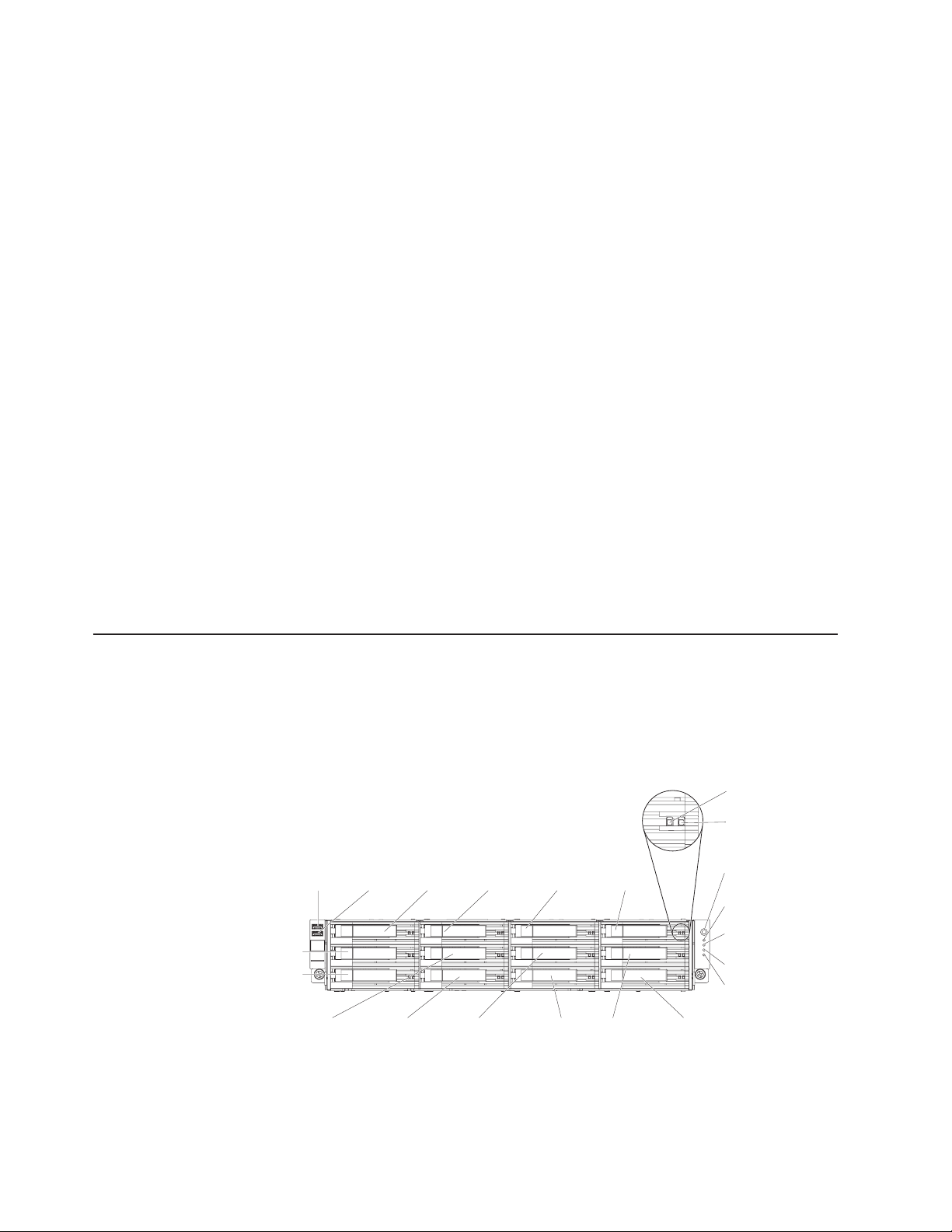
Server controls, LEDs, and connectors
This section describes the controls, light-emitting diodes (LEDs), and connectors.
Front view
The following illustration shows the controls, connectors, and hard disk drive bays
on the front of the server.
USB 1
connector
Drive bay 1
Drive bay 2
USB connectors: Connect a USB device, such as USB mouse or keyboard to
either of these connectors.
USB 2
connector
Drive bay 0
Drive bay 3 Drive bay 6 Drive bay 9
Hard disk drive
activity LED (green)
Hard disk drive
status LED (amber)
Power control
button
Power supply
LED
Hard disk drive
activity LED (front panel)
Locator LED
System error
LED
Drive bay 8Drive bay 5
Drive bay 11Drive bay 4 Drive bay 7 Drive bay 10
10 IBM System x3630 M3 Type 7377: Problem Determination and Service Guide
Page 29

Hard disk drive activity LED (front panel): When this LED is flashing, it indicates
that the drive is in use. This function is reserved for simple-swap models. For
existing models, please see the hot-swap hard disk drive activity and status LEDs
(green and amber) that pass from the backplane as the indicators for any activity or
warning.
Hard disk drive status LED (amber): This amber LED is used on hot-swap
SAS/SATA hard disk drives. Each hot-swap hard disk drive has a status LED. When
this LED is lit, it indicates that the drive has failed. When this LED is flashing slowly
(one flash per second), it indicates that the drive is being rebuilt as part of a RAID
configuration. When the LED is flashing rapidly (three flashes per second), it
indicates that the controller is identifying the drive.
Operator information panel: This panel contains the power control button and
light-emitting diodes (LEDs).
Power-control button and power-on LED: Press this button to turn the server on
and off manually or to wake the server from a reduced-power state. The states of
the green power-on LED are as follows:
Off: AC power is not present, or the power supply or the LED itself has failed.
Flashing rapidly (4 times per second): The server is turned off and is not
ready to be turned on. The power-control button is disabled. This will last
approximately 20 to 40 seconds.
Flashing slowly (once per second): The server is turned off and is ready to be
turned on. You can press the power-control button to turn on the server.
Lit: The server is turned on.
Fading on and off: The server is in a reduced-power state. To wake the server,
press the power-control button or use the IMM Web interface. See “Logging on
to the Web interface” on page 245 for information on logging on to the IMM Web
interface.
Hard disk drive activity LED (green): This green LED is used on hot-swap
SAS/SATA hard disk drives. Each hot-swap hard disk drive has an activity LED.
When this LED is flashing, it indicates that the drive is in use.
Locator LED: Use this blue LED to visually locate the server among other servers.
You can use IBM Systems Director to light this LED remotely. This LED is controlled
by the IMM.
System-error LED: When this amber LED is lit, it indicates that a system error has
occurred. This LED is controlled by the IMM.
Optional DVD-eject button: Press this button to release a CD or DVD from the
optional DVD drive.
Optional DVD drive activity LED: When this LED is lit, it indicates that the
optional DVD drive is in use.
Chapter 2. Introduction 11
Page 30
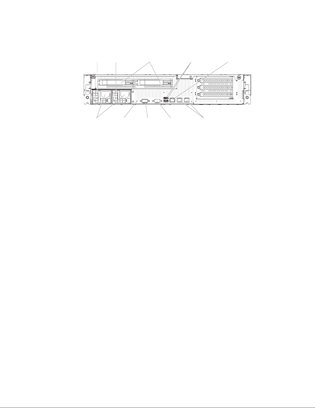
Rear view
The following illustration shows the connectors on the rear of the server.
Power
supply 1
Power cord
connectors
Power
supply 2
AC
DC
AC
DC
NMI button Serial
Optional SAS/SATA
hard disk drives
connector
USB 3 & 4
connectors
Video
connector
System management
Ethernet connector
Ethernet 1& 2
connectors
Ethernet connectors: Use any of these connectors to connect the server to a
network. When you use the Ethernet 1 connector, the network can be shared with
the IMM through a single network cable.
Power-cord connector: Connect the power cord to this connector.
Note: Power supply 1 is the default/primary power supply. If the server has two
power supplies and if any of the power supplies fails, the server will not have
redundant power and you must replace the power supply immediately.
USB connectors: Connect a USB device, such as USB mouse or keyboard to
either of these connectors.
NMI button: Press this button to force a nonmaskable interrupt to the
microprocessor. You might have to use a pen or the end of a straightened paper
clip to press the button. It allows you to blue screen the server and take a memory
dump (use this button only when directed by the IBM service support).
Serial connector: Connect a 9-pin serial device to this connector. The serial port is
shared with the integrated management module (IMM). The IMM can take control of
the shared serial port to perform text console redirection and to redirect serial
traffic, using Serial over LAN (SOL).
Video connector: Connect a monitor to this connector. The video connectors on
the front and rear of the server can be used simultaneously.
Note: The maximum video resolution is 1600 x 1200 at 85 Hz.
Systems-management Ethernet connector: Use this connector to connect the
server to a network for systems-management information control. This connector is
used only by the IMM.
12 IBM System x3630 M3 Type 7377: Problem Determination and Service Guide
Page 31

The following illustration shows the LEDs on the rear of the server.
AC power
LED
DC power
LED
Power-supply
error LED
AC
DC
AC
DC
Ethernet activity
LED
Ethernet link
LED
Ethernet activity LEDs: When these LEDs are lit, they indicate that the server is
transmitting to or receiving signals from the Ethernet LAN that is connected to the
Ethernet port.
Ethernet link LEDs: When these LEDs are lit, they indicate that there is an active
link connection on the 10BASE-T, 100BASE-TX, or 1000BASE-TX interface for the
Ethernet port.
AC power LED: Each hot-swap power supply has an ac power LED and a dc
power LED. When the ac power LED is lit, it indicates that sufficient power is
coming into the power supply through the power cord. During typical operation, both
the ac and dc power LEDs are lit. For any other combination of LEDs, see
“Power-supply LEDs.”
DC power LED: Each hot-swap power supply has a dc power LED and an ac
power LED. When the dc power LED is lit, it indicates that the power supply is
supplying adequate dc power to the system. During typical operation, both the ac
and dc power LEDs are lit. For any other combination of LEDs, see “Power-supply
LEDs.”
Power-supply error LED: When the power-supply error LED is lit, it indicates that
the power supply has failed.
Power-supply LEDs
The following illustration shows the power-supply LEDs on the rear of the server.
For more information about solving power-supply problems, see “Power problems”
on page 51.
AC power
LED
DC power
LED
Power-supply
error LED
AC
DC
The following table describes the problems that are indicated by various
combinations of the power-supply LEDs and suggested actions to correct the
detected problems.
AC
DC
AC
DC
Chapter 2. Introduction 13
Page 32

Table 2. Power-supply LEDs
Power-supply LEDs
AC
(green)DC(green)
On On Off Normal operation
Off Off Off No ac power to
Off Off On No ac power to
Off On Off Faulty power
Off On On Faulty power
On Off Off Power supply not
On Off or
Flashing
On On On Power supply is
Error
(amber)
On Faulty power
Description Action Notes
the server or a
problem with the
ac power source
the server or a
problem with the
ac power source
and the power
supply had
detected an
internal problem
supply
supply
fully seated,
faulty system
board, or faulty
power supply
supply
faulty but still
operational
1. Check the ac power to the server.
2. Make sure that the power cord is
connected to a functioning power
source.
3. Turn the server off and then turn the
server back on.
4. If the problem remains, replace the
power supply.
1. Replace the power supply.
2. Make sure that the power cord is
connected to a functioning power
source.
Replace the power supply.
Replace the power supply.
1. Reseat the power supply.
2. Replace the power supply.
3. (Trained service technician only)
Replace the system board.
Note: Make sure the technician
refreshes the VPD.
Replace the power supply.
Replace the power supply.
This is a normal
condition when no
ac power is present.
This happens only
when a second
power supply is
providing power to
the server.
Typically indicates
that a power supply
is not fully seated.
14 IBM System x3630 M3 Type 7377: Problem Determination and Service Guide
Page 33

Internal connectors, LEDs, and jumpers
The illustrations in this section show the LEDs, connectors, and jumpers on the
internal boards. The illustrations might differ slightly from your hardware.
System-board internal connectors
The following illustration shows the internal connectors on the system board.
Chapter 2. Introduction 15
Page 34

System-board DIMM connectors
The following illustration shows the DIMM connectors on the system board.
16 IBM System x3630 M3 Type 7377: Problem Determination and Service Guide
Page 35

System-board external connectors
The following illustration shows the external input/output connectors on the system
board.
Chapter 2. Introduction 17
Page 36

System-board jumpers
This section describes the jumpers on the system board.
Table 3. System board jumpers
Jumper number Jumper name Jumper setting
JP2 Clear CMOS jumper
JP3 UEFI boot recovery jumper
Notes:
v If no jumper is present, the server responds as if the pins are set to 1 and 2.
v Changing the position of the UEFI recovery jumper from pins 1 and 2 to pins 2 and 3
before the server is turned on sets the UEFI recovery process. Do not change the jumper
pin position after the server is turned on. This can cause an unpredictable problem.
v Pins 1 and 2: Normal
(default) - This keeps the
CMOS data.
v Pins 2 and 3: This clears
the CMOS data such as
power-on password and
loads the default UEFI
settings.
v Pins 1 and 2: Normal
(default) Loads the primary
firmware ROM page.
v Pins 2 and 3: Loads the
secondary (backup)
firmware ROM page.
18 IBM System x3630 M3 Type 7377: Problem Determination and Service Guide
Page 37

Notes:
1. Before you change any switch settings or move any jumpers, turn off the server;
then, disconnect all power cords and external cables. (Review the information in
“Safety” on page vii, “Installation guidelines” on page 133, and “Handling
static-sensitive devices” on page 135.)
2. Any system-board switch or jumper blocks that are not shown in the illustrations
in this document are reserved.
Chapter 2. Introduction 19
Page 38

System-board LEDs
The following illustration shows the light-emitting diodes (LEDs) on the system
board.
Note: Error LEDs remain lit only while the server is connected to power. If you
disconnect power to the server, you can press and hold the light path diagnostics
button to light the error LEDs on the system board.
LED name Description
Error LEDs When an error LED is lit, it indicates that the associated
component has failed.
H8 heartbeat When this LED is flashing, it indicates that the power
management controller is functioning normally.
IMM heartbeat When this LED is flashing at a constant rate of every other
second, it indicates normal operation of the IMM controller. When
this LED is flashing at a constant rate of every other half-second,
it indicates that the IMM controller is initializing or is not
functional.
Microprocessor
mismatch
Standby power When this LED is lit, it indicates that the server is connected to
When this LED is lit, it indicates that microprocessor 1 is not
installed, or the microprocessors do not have the same cache
size and type, and clock speed.
an ac power source and that the power supply has supplied the
5–volt standby voltage to the system board.
20 IBM System x3630 M3 Type 7377: Problem Determination and Service Guide
Page 39

Fan board connectors
The following illustration shows the connectors on the fan board.
Fan 1 connector Fan 2 connector Fan 3 connector Fan 4 connector
Thermal sensor
connector
Fan 5 connector
Signal connector
PCI riser-card adapter connectors
The following illustration shows the connectors on the PCI riser card for
user-installable PCI adapters.
Power connector
Fan 6 connector
Chapter 2. Introduction 21
Page 40

22 IBM System x3630 M3 Type 7377: Problem Determination and Service Guide
Page 41

Chapter 3. Diagnostics
This chapter describes the diagnostic tools that are available to help you solve
problems that might occur in the server.
If you cannot locate and correct a problem by using the information in this chapter,
see Appendix A, “Getting help and technical assistance,” on page 259 for more
information.
Diagnostic tools
The following tools are available to help you diagnose and solve hardware-related
problems:
v Troubleshooting tables
These tables list problem symptoms and actions to correct the problems. See
“Troubleshooting tables” on page 40.
v Light path diagnostics
Use the light path diagnostics to diagnose system errors quickly. See
“System-board LEDs” on page 20 or “Error LEDs” on page 54 for more
information.
v IBM Dynamic System Analysis
IBM Dynamic System Analysis (DSA) collects and analyzes system information to
aid in diagnosing server problems. DSA collects the following information about
the server:
– Drive health information
– Event logs for ServeRAID controllers and service processors
– Hardware inventory, including PCI and USB information
– Installed applications and hot fixes
– Kernel modules
– Light path diagnostics status
– Network interfaces and settings
– Performance data and details about processes that are running
– RAID and controller configuration
– Service processor (integrated management module) status and configuration
– System configuration
– Vital product data and firmware information
DSA creates a DSA log, which is a chronologically ordered merge of the
system-event log (as the IPMI event log), the integrated management module
(IMM) chassis-event log (as the ASM event log), and the operating-system event
logs. You can send the DSA log as a file to IBM service or view the information
as a text file or HTML file.
For more information, see “IBM Dynamic System Analysis” on page 59.
v IBM Electronic Service Agent
IBM Electronic Service Agent is a software tool that monitors the server for
hardware error events and automatically submits electronic service requests to
IBM service and support. Also, it can collect and transmit system configuration
information on a scheduled basis so that the information is available to you and
your support representative. It uses minimal system resources, is available free
of charge, and can be downloaded from the Web. For more information and to
download Electronic Service Agent, go to http://www.ibm.com/support/electronic/.
© Copyright IBM Corp. 2014 23
Page 42

Event logs
Note: When you enable software RAID on simple-swap models of the server, you
will no longer be able use the IBM Director, Dynamic System Analysis (DSA), and
ServerGuide tools to configure, diagnose, or update hard drives on simple-swap
models. However, you will still be able use these tools to configure or diagnose
other simple-swap server model features and components.
Error codes and messages are displayed in the following types of event logs:
v POST event log: This log contains the three most recent error codes and
messages that were generated during POST. You can view the POST event log
through the Setup utility.
v System-event log: This log contains POST and system management interrupt
(SMI) events and all events that are generated by the BMC that is embedded in
the IMM. You can view the system-event log through the Setup utility and through
the Dynamic System Analysis (DSA) program (as the IPMI event log).
The system-event log is limited in size. When it is full, new entries will not
overwrite existing entries; therefore, you must periodically save and then clear
the system-event log through the Setup utility. When you are troubleshooting, you
might have to save and then clear the system-event log to make the most recent
events available for analysis.
Messages are listed on the left side of the screen, and details about the selected
message are displayed on the right side of the screen. To move from one entry
to the next, use the Up Arrow (↑) and Down Arrow (↓) keys.
Some IMM sensors cause assertion events to be logged when their setpoints are
reached. When a setpoint condition no longer exists, a corresponding
deassertion event is logged. However, not all events are assertion-type events.
v Integrated management module (IMM) event log: This log contains a filtered
subset of all IMM, POST, and system management interrupt (SMI) events. You
can view the IMM event log through the IMM Web interface and through the
Dynamic System Analysis (DSA) program (as the ASM event log).
v
v DSA log: This log is generated by the Dynamic System Analysis (DSA) program,
and it is a chronologically ordered merge of the system-event log (as the IPMI
event log), the IMM chassis-event log (as the ASM event log), and the
operating-system event logs. You can view the DSA log through the DSA
program.
Viewing event logs from the Setup utility
To view the POST event log or system-event log, complete the following steps:
1. Turn on the server.
2. When the prompt <F1> Setup is displayed, press F1. If you have set both a
power-on password and an administrator password, you must type the
administrator password to view the event logs.
3. Select System Event Logs and use one of the following procedures:
v To view the POST event log, select POST Event Viewer.
v To view the system-event log, select System Event Log.
Viewing event logs without restarting the server
If the server is not hung, methods are available for you to view one or more event
logs without having to restart the server.
24 IBM System x3630 M3 Type 7377: Problem Determination and Service Guide
Page 43

If you have installed Dynamic System Analysis (DSA) Portable or DSA Installable,
you can use it to view the system-event log (as the IPMI event log), the IMM event
log (as the ASM event log), the operating-system event logs, or the merged DSA
log. You can also use DSA Preboot to view these logs, although you must restart
the server to use DSA Preboot. To install DSA Portable, DSA Installable, or DSA
Preboot or to download a DSA Preboot CD image, go to http://www.ibm.com/
systems/support/supportsite.wss/docdisplay?lndocid=SERV-DSA
&brandind=5000008 or complete the following steps.
Note: Changes are made periodically to the IBM Web site. The actual procedure
might vary slightly from what is described in this document.
1. Go to http://www.ibm.com/systems/support/.
2. Under IBM Systems support, click System x.
3. Under Popular links, click Software and device drivers.
4. Under Related downloads, click Dynamic System Analysis (DSA) to display
the matrix of downloadable DSA files.
If IPMItool is installed in the server, you can use it to view the system-event log.
Most recent versions of the Linux operating system come with a current version of
IPMItool. For an overview of IPMI, go to http://www.ibm.com/developerworks/linux/
blueprints/ and click Using Intelligent Platform Management Interface (IPMI) on
IBM Linux platforms.
Note: Changes are made periodically to the IBM Web site. The actual procedure
might vary slightly from what is described in this document.
You can view the IMM event log through the Event Log link in the IMM Web
interface.
The following table describes the methods that you can use to view the event logs,
depending on the condition of the server. The first two conditions generally do not
require that you restart the server.
Table 4. Methods for viewing event logs
Condition Action
The server is not hung and is connected to a
network.
The server is not hung and is not connected
to a network.
Use any of the following methods:
v Run DSA Portable or DSA Installable to
view the event logs or create an output file
that you can send to IBM service.
v In a Web browser, type the IP address of
the IMM and go to the Event Log page.
v Use IPMItool to view the system-event log.
Use IPMItool locally to view the system-event
log.
Chapter 3. Diagnostics 25
Page 44

POST
Table 4. Methods for viewing event logs (continued)
Condition Action
The server is hung. v If DSA Preboot is installed, restart the
server and press F2 to start DSA Preboot
and view the event logs.
v If DSA Preboot is not installed, insert the
DSA Preboot CD and restart the server to
start DSA Preboot and view the event
logs.
v Alternatively, you can restart the server
and press F1 to start the Setup utility and
view the POST event log or system-event
log. For more information, see “Viewing
event logs from the Setup utility” on page
24.
When you turn on the server, it performs a series of tests to check the operation of
the server components and some optional devices in the server. This series of tests
is called the power-on self-test, or POST. This server does not use beep codes for
server status.
If a power-on password is set, you must type the password and press Enter, when
you are prompted, for POST to run.
POST error messages
The following table describes the POST error messages and suggested actions to
correct the detected problems.
26 IBM System x3630 M3 Type 7377: Problem Determination and Service Guide
Page 45

v Follow the suggested actions in the order in which they are listed in the Action column until the problem
is solved.
v See Chapter 4, “Parts listing, Type 7377 server,” on page 125 to determine which components are
customer replaceable units (CRU) and which components are field replaceable units (FRU).
v If an action step is preceded by “(Trained service technician only),” that step must be performed only by a
trained service technician.
Error code Description Action
0010002 Microprocessor not supported
1. (Trained service technician only) Reseat the following
components one at a time, in the order shown, restarting
the server each time:
a. Microprocessor 1
b. Microprocessor 2 (if installed)
2. (Trained service technician only) Remove microprocessor
2 and restart the server.
3. (Trained service technician only) Remove microprocessor
1 and install microprocessor 2 in the microprocessor 1
connector. Restart the server. If the error is corrected,
microprocessor 1 is bad and must be replaced.
4. (Trained service technician only) Replace the following
components one at a time, in the order shown, restarting
the server each time:
a. Microprocessor 1
b. Microprocessor 2
c. System board
0011000 Invalid microprocessor type
1. Update the system firmware (see “Updating the firmware”
on page 233).
2. (Trained service technician only) Remove and replace the
affected microprocessor (error LED is lit) with a supported
type.
0011002 Microprocessor mismatch
1. Run the Setup utility and view the microprocessor
information to compare the installed microprocessor
specifications.
2. (Trained service technician only) Remove and replace one
of the microprocessors so that they both match.
0011004 Microprocessor failed BIST
1. Update the system firmware (see “Updating the firmware”
on page 233).
2. (Trained service technician only) Reseat microprocessor 2.
3. (Trained service technician only) Replace the following
components one at a time, in the order shown, restarting
the server each time:
a. Microprocessor
b. System board
001100A Microcode update failed
1. Update the system firmware (see “Updating the firmware”
on page 233).
2. (Trained service technician only) Replace the
microprocessor.
Chapter 3. Diagnostics 27
Page 46

v Follow the suggested actions in the order in which they are listed in the Action column until the problem
is solved.
v See Chapter 4, “Parts listing, Type 7377 server,” on page 125 to determine which components are
customer replaceable units (CRU) and which components are field replaceable units (FRU).
v If an action step is preceded by “(Trained service technician only),” that step must be performed only by a
trained service technician.
Error code Description Action
0018010 Microprocessors of the same model
have mismatched stepping ID.
0018009 Microprocessors have mismatched
core speed.
001800B Microprocessors have one or more
cache levels with mismatched size.
0018005 Microprocessors have mismatched
number of COREs.
0018006 Microprocessors have mismatched
QPI speed.
0018007 Microprocessors have mismatched
power segments.
0018008 Microprocessors have mismatched
internal DDR3 frequency.
1. Run the Setup utility and select System Information →
System Summary → Processor Details to view the
microprocessor information to compare the installed
microprocessor specifications.
2. (Trained service technician only) Remove and replace one
of the microprocessors so that they both match.
1. Run the Setup utility and select System Information →
System Summary → Processor Details to view the
microprocessor information to compare the installed
microprocessor specifications.
2. (Trained service technician only) Remove and replace one
of the microprocessors so that they both match.
1. Run the Setup utility and select System Information →
System Summary → Processor Details to view the
microprocessor information to compare the installed
microprocessor specifications.
2. (Trained service technician only) Remove and replace one
of the microprocessors so that they both match.
1. Run the Setup utility and select System Information →
System Summary → Processor Details to view the
microprocessor information to compare the installed
microprocessor specifications.
2. (Trained service technician only) Remove and replace one
of the microprocessors so that they both match.
1. Run the Setup utility and select System Information →
System Summary → Processor Details to view the
microprocessor information to compare the installed
microprocessor specifications.
2. (Trained service technician only) Remove and replace one
of the microprocessors so that they both match.
1. Run the Setup utility and select System Information →
System Summary → Processor Details to view the
microprocessor information to compare the installed
microprocessor specifications.
2. (Trained service technician only) Remove and replace one
of the microprocessors so that they both match.
1. Run the Setup utility and select System Information →
System Summary → Processor Details to view the
microprocessor information to compare the installed
microprocessor specifications.
2. (Trained service technician only) Remove and replace one
of the microprocessors so that they both match.
28 IBM System x3630 M3 Type 7377: Problem Determination and Service Guide
Page 47

v Follow the suggested actions in the order in which they are listed in the Action column until the problem
is solved.
v See Chapter 4, “Parts listing, Type 7377 server,” on page 125 to determine which components are
customer replaceable units (CRU) and which components are field replaceable units (FRU).
v If an action step is preceded by “(Trained service technician only),” that step must be performed only by a
trained service technician.
Error code Description Action
0050001 DIMM disabled Note: Each time you install or remove a DIMM, you must
disconnect the server from the power source; then, wait 10
seconds before restarting the server.
1. Make sure the DIMM is installed correctly (see “Installing a
memory module” on page 162).
2. If the DIMM was disabled because of a memory fault,
follow the suggested actions for that error event and
restart the server.
3. Check the IBM support website for an applicable retain tip
or firmware update that applies to this memory event. If no
memory fault is recorded in the logs and no DIMM
connector error LED is lit, you can re-enable the DIMM
through the Setup utility or the Advanced Settings Utility
(ASU).
0051003 Uncorrectable DIMM error Note: Each time you install or remove a DIMM, you must
disconnect the server from the power source; then, wait 10
seconds before restarting the server.
1. Check the IBM support website for an applicable retain tip
or firmware update that applies to this memory error.
2. Manually re-enable all affected DIMMs if the server
firmware version is older than UEFI v1.10. If the server
firmware version is UEFI v1.10 or newer, disconnect and
reconnect the server to the power source and restart the
server.
3. If the problem remains, replace the failing DIMM (see
“Removing a memory module (DIMM)” on page 161 and
“Installing a memory module” on page 162).
4. (Trained service technician only) If the problem occurs on
the same DIMM connector, check the DIMM connector. If
the connector contains any foreign material or is
damaged, replace the system board (see “Removing the
system board” on page 228 and “Installing the system
board” on page 230).
5. (Trained service technician only) Remove the affected
microprocessor and check the microprocessor socket pins
for any damaged pins. If a damage is found, replace the
system board (see “Removing the system board” on page
228 and “Installing the system board” on page 230).
6. (Trained Service technician only) Replace the affected
microprocessor (see “Removing a microprocessor and
heat sink” on page 221 and “Installing a microprocessor
and heat sink” on page 223).
Chapter 3. Diagnostics 29
Page 48

v Follow the suggested actions in the order in which they are listed in the Action column until the problem
is solved.
v See Chapter 4, “Parts listing, Type 7377 server,” on page 125 to determine which components are
customer replaceable units (CRU) and which components are field replaceable units (FRU).
v If an action step is preceded by “(Trained service technician only),” that step must be performed only by a
trained service technician.
Error code Description Action
0051006 DIMM mismatch detected Note: Each time you install or remove a DIMM, you must
disconnect the server from the power source; then, wait 10
seconds before restarting the server.
Make sure that the DIMMs match and are installed in the
correct sequence (see “Installing a memory module” on page
162).
0051009 No memory detected Note: Each time you install or remove a DIMM, you must
disconnect the server from the power source; then, wait 10
seconds before restarting the server.
1. Make sure one or more DIMMs are installed in the server.
2. Reseat the DIMMs and restart the server (see “Removing
a memory module (DIMM)” on page 161 and “Installing a
memory module” on page 162).
3. Make sure that the DIMMs match and are installed in the
correct sequence (see “Installing a memory module” on
page 162).
4. (Trained service technician only) Replace the
microprocessor that controls the failing DIMMs (see
“Removing a microprocessor and heat sink” on page 221
and “Installing a microprocessor and heat sink” on page
223).
5. (Trained service technician only) Replace the system
board (see “Removing the system board” on page 228
and “Installing the system board” on page 230).
005100A No usable memory detected Note: Each time you install or remove a DIMM, you must
disconnect the server from the power source; then, wait 10
seconds before restarting the server.
1. Make sure one or more DIMMs are installed in the server.
2. Reseat the DIMMs and restart the server (see “Removing
a memory module (DIMM)” on page 161 and “Installing a
memory module” on page 162).
3. Make sure that the DIMMs match and are installed in the
correct sequence (see “Installing a memory module” on
page 162).
4. Clear CMOS memory to ensure that all DIMM connectors
are enabled (see “Removing the system battery” on page
142 and “Installing the system battery” on page 143). Note
that all firmware settings will be reset to the default
settings.
30 IBM System x3630 M3 Type 7377: Problem Determination and Service Guide
Page 49

v Follow the suggested actions in the order in which they are listed in the Action column until the problem
is solved.
v See Chapter 4, “Parts listing, Type 7377 server,” on page 125 to determine which components are
customer replaceable units (CRU) and which components are field replaceable units (FRU).
v If an action step is preceded by “(Trained service technician only),” that step must be performed only by a
trained service technician.
Error code Description Action
0058001 PFA threshold exceeded Note: Each time you install or remove a DIMM, you must
disconnect the server from the power source; then, wait 10
seconds before restarting the server.
1. Check the IBM support website for an applicable retain tip
or firmware update that applies to this memory error.
2. Swap the affected DIMMs (as indicated by the error LEDs
on the system board or the event logs) to a different
memory channel or microprocessor (see “Installing a
memory module” on page 162).
3. If the error still occurs on the same DIMM, replace the
affected DIMM.
4. (Trained service technician only) If the problem occurs on
the same DIMM connector, check the DIMM connector. If
the connector contains any foreign material or is
damaged, replace the system board (see “Removing the
system board” on page 228 and “Installing the system
board” on page 230).
5. (Trained service technician only) Remove the affected
microprocessor and check the microprocessor socket pins
for any damaged pins. If a damage is found, replace the
system board (see “Removing the system board” on page
228 and “Installing the system board” on page 230).
6. (Trained Service technician only) Replace the affected
microprocessor (see “Removing a microprocessor and
heat sink” on page 221 and “Installing a microprocessor
and heat sink” on page 223).
0058007 DIMM population is unsupported Note: Each time you install or remove a DIMM, you must
disconnect the server from the power source; then, wait 10
seconds before restarting the server.
1. Reseat the DIMMs and restart the server (see “Removing
a memory module (DIMM)” on page 161 and “Installing a
memory module” on page 162).
2. Make sure that the DIMMs are installed in the proper
sequence (see “Installing a memory module” on page
162).
Chapter 3. Diagnostics 31
Page 50

v Follow the suggested actions in the order in which they are listed in the Action column until the problem
is solved.
v See Chapter 4, “Parts listing, Type 7377 server,” on page 125 to determine which components are
customer replaceable units (CRU) and which components are field replaceable units (FRU).
v If an action step is preceded by “(Trained service technician only),” that step must be performed only by a
trained service technician.
Error code Description Action
0058008 DIMM failed memory test Note: Each time you install or remove a DIMM, you must
disconnect the server from the power source; then, wait 10
seconds before restarting the server.
1. Check the IBM support website for an applicable retain tip
or firmware update that applies to this memory error.
2. Manually re-enable all affected DIMMs if the server
firmware version is older than UEFI v1.10. If the server
firmware version is UEFI v1.10 or newer, disconnect and
reconnect the server to the power source and restart the
server.
3. Swap the affected DIMMs (as indicated by the error LEDs
on the system board or the event logs) to a different
memory channel or microprocessor (see “Installing a
memory module” on page 162 for memory population).
4. If the problem is related to a DIMM, replace the failing
DIMM (see “Removing a memory module (DIMM)” on
page 161 and “Installing a memory module” on page 162).
5. (Trained service technician only) If the problem occurs on
the same DIMM connector, check the DIMM connector. If
the connector contains any foreign material or is
damaged, replace the system board (see “Removing the
system board” on page 228 and “Installing the system
board” on page 230).
6. (Trained service technician only) Remove the affected
microprocessor and check the microprocessor socket pins
for any damaged pins. If a damage is found, replace the
system board (see “Removing the system board” on page
228 and “Installing the system board” on page 230).
7. (Trained service technician only) If the problem is related
to microprocessor socket pins, replace the system board
(see “Removing the system board” on page 228 and
“Installing the system board” on page 230).
8. (Trained Service technician only) Replace the affected
microprocessor (see “Removing a microprocessor and
heat sink” on page 221 and “Installing a microprocessor
and heat sink” on page 223).
0058015 Start to activate spare memory
channel
00580A1 Invalid DIMM population for mirroring
mode
00580A4 Memory population changed Information only. Memory has been added, moved, or
Information only. A failed DIMM has been detected to activate
the memory online-spare feature. Check the event log for
uncorrected DIMM failure events.
Note: Each time you install or remove a DIMM, you must
disconnect the server from the power source; then, wait 10
seconds before restarting the server.
1. If a fault LED is lit, resolve the failure.
2. Install the DIMMs in the correct sequence (see “Installing
a memory module” on page 162).
changed.
32 IBM System x3630 M3 Type 7377: Problem Determination and Service Guide
Page 51

v Follow the suggested actions in the order in which they are listed in the Action column until the problem
is solved.
v See Chapter 4, “Parts listing, Type 7377 server,” on page 125 to determine which components are
customer replaceable units (CRU) and which components are field replaceable units (FRU).
v If an action step is preceded by “(Trained service technician only),” that step must be performed only by a
trained service technician.
Error code Description Action
00580A5 Mirror failover complete Information only. Memory redundancy has been lost. Check
the event log for uncorrected DIMM failure events (See “Event
logs” on page 24 for more information).
00580A6 Spare memory channel activated Information only. Memory online-spare channel has been
activated to back up a failed DIMM. Check the event log for
uncorrected DIMM failure events.
0068002 CMOS battery cleared
1. Reseat the battery.
2. Clear the CMOS memory (see “System-board jumpers” on
page 18).
3. Replace the following components one at a time, in the
order shown, restarting the server each time:
a. Battery
b. (Trained service technician only) System board
2011001 PCI-X SERR
1. Check the PCI error LEDs.
2. Reseat all affected adapters and riser cards.
3. Update the PCI device firmware.
4. Remove the adapter from the riser card.
5. Replace the following components one at a time, in the
order shown, restarting the server each time:
a. Riser card
b. (Trained service technician only) System board
2018001 PCI Express uncorrected or
uncorrected error
1. Check the PCI error LEDs.
2. Reseat all affected adapters and riser cards.
3. Update the PCI device firmware.
4. Remove any adapters from the riser cards.
5. Replace the following components one at a time, in the
order shown, restarting the server each time:
a. Riser card
b. (Trained service technician only) System board
Chapter 3. Diagnostics 33
Page 52

v Follow the suggested actions in the order in which they are listed in the Action column until the problem
is solved.
v See Chapter 4, “Parts listing, Type 7377 server,” on page 125 to determine which components are
customer replaceable units (CRU) and which components are field replaceable units (FRU).
v If an action step is preceded by “(Trained service technician only),” that step must be performed only by a
trained service technician.
Error code Description Action
2018002 Option ROM resource allocation
failure
3xx0007 (xx
can be 00 -
19)
3038003 Firmware corrupted
3048005 Booted secondary (backup) UEFI
3048006 Booted secondary (backup) UEFI
Firmware fault detected, system
halted
image
image because of ABR
Informational message that some devices might not be
initialized.
1. If possible, rearrange the order of the adapters in the PCI
slots to change the load order of the optional-device ROM
code.
2. Run the Setup utility, select Start Options, and change
the boot priority to change the load order of the
optional-device ROM code.
3. Run the Setup utility and disable some other resources, if
their functions are not being used, to make more space
available:
v Select Start Options and Planar Ethernet
(PXE/DHCP) to disable the integrated Ethernet
controller ROM.
v Select Advanced Functions, then PCI Bus Control,
then PCI ROM Control Execution to disable the ROM
of adapters in the PCI slots.
v Select Devices and I/O Ports to disable any of the
integrated devices.
4. Replace the following components one at a time, in the
order shown, restarting the server each time:
a. Each adapter
b. (Trained service technician only) System board
1. Recover the server firmware to the latest level.
2. Undo any recent configuration changes, or clear CMOS
memory to restore the settings to the default values.
3. Remove any recently installed hardware.
1. Run the Setup utility, select Load Default Settings, and
save the settings to recover the server firmware.
2. (Trained service technician only) Replace the system
board.
Note: Make sure the technician refreshes the VPD.
Information only. The backup switch was used to boot the
secondary bank.
1. Run the Setup utility, select Load Default Settings, and
save the settings to recover the primary UEFI settings.
2. Turn off the server and remove it from the power source.
3. Reconnect the server to the power source, and then turn
on the server.
34 IBM System x3630 M3 Type 7377: Problem Determination and Service Guide
Page 53

v Follow the suggested actions in the order in which they are listed in the Action column until the problem
is solved.
v See Chapter 4, “Parts listing, Type 7377 server,” on page 125 to determine which components are
customer replaceable units (CRU) and which components are field replaceable units (FRU).
v If an action step is preceded by “(Trained service technician only),” that step must be performed only by a
trained service technician.
Error code Description Action
305000A RTC date/time is incorrect
1. Adjust the date and time settings in the Setup utility, and
then restart the server.
2. Reseat the battery.
3. Replace the following components one at a time, in the
order shown, restarting the server each time:
a. Battery
b. (Trained service technician only) System board
3058001 System configuration invalid
1. Run the Setup utility, and select Save Settings.
2. Run the Setup utility, select Load Default Settings, and
save the settings.
3. Reseat the following components one at a time in the
order shown, restarting the server each time:
a. Battery
b. Failing device (if the device is a FRU, then it must be
reseated by a trained service technician only)
4. Replace the following components one at a time, in the
order shown, restarting the server each time:
a. Battery
b. Failing device (if the device is a FRU, then it must be
replaced by a trained service technician only)
c. (Trained service technician only) System board
3058004 Three boot failures
1. Undo any recent system changes, such as new settings or
newly installed devices.
2. Make sure that the server is attached to a reliable power
source.
3. Remove all hardware that is not listed on the
ServerProven Web site.
4. Make sure that the operating system is not corrupted.
5. Run the Setup utility, save the configuration, and then
restart the server.
6. See “Problem determination tips” on page 122.
3108007 System configuration restored to
default settings
3138002 Boot configuration error
Information only. This is message is usually associated with
the CMOS battery clear event.
1. Remove any recent configuration changes that you made
in the Setup utility.
2. Run the Setup utility, select Load Default Settings, and
save the settings.
Chapter 3. Diagnostics 35
Page 54

v Follow the suggested actions in the order in which they are listed in the Action column until the problem
is solved.
v See Chapter 4, “Parts listing, Type 7377 server,” on page 125 to determine which components are
customer replaceable units (CRU) and which components are field replaceable units (FRU).
v If an action step is preceded by “(Trained service technician only),” that step must be performed only by a
trained service technician.
Error code Description Action
3808000 IMM communication failure
3808002 Error updating system configuration
to IMM
3808003 Error retrieving system configuration
from IMM
3808004 IMM system event log full
3818001 Core Root of Trust Measurement
(CRTM) update failed
3818002 Core Root of Trust Measurement
(CRTM) update aborted
3818003 Core Root of Trust Measurement
(CRTM) flash lock failed
3818004 Core Root of Trust Measurement
(CRTM) system error
1. Remove power from the server for 30 seconds, and then
reconnect the server to power and restart it.
2. Update the IMM firmware.
3. Make sure that the IMM key is seated and not damaged.
4. (Trained service technician only) Replace the system
board.
Note: Make sure the technician refreshes the VPD.
1. Remove power from the server, and then reconnect the
server to power and restart it.
2. Run the Setup utility and select Save Settings.
3. Update the firmware.
1. Remove power from the server, and then reconnect the
server to power and restart it.
2. Run the Setup utility and select Save Settings.
3. Update the IMM firmware.
v When out-of-band, use the IMM Web interface or IPMItool
to clear the logs from the operating system.
v When using the local console:
1. Run the Setup utility.
2. Select System Event Log.
3. Select Clear System Event Log.
4. Restart the server.
1. Run the Setup utility, select Load Default Settings, and
save the settings.
2. (Trained service technician only) Replace the system
board.
1. Run the Setup utility, select Load Default Settings, and
save the settings.
2. (Trained service technician only) Replace the system
board.
1. Run the Setup utility, select Load Default Settings, and
save the settings.
2. (Trained service technician only) Replace the system
board.
1. Run the Setup utility, select Load Default Settings, and
save the settings.
2. (Trained service technician only) Replace the system
board.
36 IBM System x3630 M3 Type 7377: Problem Determination and Service Guide
Page 55

v Follow the suggested actions in the order in which they are listed in the Action column until the problem
is solved.
v See Chapter 4, “Parts listing, Type 7377 server,” on page 125 to determine which components are
customer replaceable units (CRU) and which components are field replaceable units (FRU).
v If an action step is preceded by “(Trained service technician only),” that step must be performed only by a
trained service technician.
Error code Description Action
3818005 Current Bank Core Root of Trust
Measurement (CRTM) capsule
signature invalid
1. Run the Setup utility, select Load Default Settings, and
save the settings.
2. (Trained service technician only) Replace the system
board.
3818006 Opposite bank CRTM capsule
signature invalid
1. Switch the server firmware bank to the backup bank (see
“Starting the backup server firmware” on page 240).
2. Run the Setup utility, select Load Default Settings, and
save the settings.
3. Switch the bank back to the primary bank.
4. (Trained service technician only) Replace the system
board.
3818007 CRTM update capsule signature
invalid
1. Run the Setup utility, select Load Default Settings, and
save the settings.
2. (Trained service technician only) Replace the system
board.
3828004 AEM power capping disabled
1. Check the settings and the event logs.
2. Make sure that the Active Energy Manager feature is
enabled in the Setup utility. Select System Settings,
Power, Active Energy, and Capping Enabled.
3. Update the server firmware.
4. Update the IMM firmware.
Chapter 3. Diagnostics 37
Page 56

Checkout procedure
The checkout procedure is the sequence of tasks that you should follow to
diagnose a problem in the server.
About the checkout procedure
Before you perform the checkout procedure for diagnosing hardware problems,
review the following information:
v Read the safety information that begins on page vii.
v The diagnostic programs provide the primary methods of testing the major
components of the server, such as the system board, Ethernet controller,
keyboard, mouse (pointing device), serial ports, and hard disk drives. You can
also use them to test some external devices. If you are not sure whether a
problem is caused by the hardware or by the software, you can use the
diagnostic programs to confirm that the hardware is working correctly.
v When you run the diagnostic programs, a single problem might cause more than
one error message. When this happens, correct the cause of the first error
message. The other error messages usually will not occur the next time you run
the diagnostic programs.
Exception: If multiple error codes or light path diagnostics LEDs indicate a
microprocessor error, the error might be in the microprocessor or in the
microprocessor socket. See “Microprocessor problems” on page 47 for
information about diagnosing microprocessor problems.
v Before you run the diagnostic programs, you must determine whether the failing
server is part of a shared hard disk drive cluster (two or more servers sharing
external storage devices). If it is part of a cluster, you can run all diagnostic
programs except the ones that test the storage unit (that is, a hard disk drive in
the storage unit) or the storage adapter that is attached to the storage unit. The
failing server might be part of a cluster if any of the following conditions is true:
– You have identified the failing server as part of a cluster (two or more servers
sharing external storage devices).
– One or more external storage units are attached to the failing server and at
least one of the attached storage units is also attached to another server or
unidentifiable device.
– One or more servers are located near the failing server.
Important: If the server is part of a shared hard disk drive cluster, run one test
at a time. Do not run any suite of tests, such as “quick” or “normal” tests,
because this might enable the hard disk drive diagnostic tests.
v If the server is halted and a POST error code is displayed, see “Event logs” on
page 24. If the server is halted and no error message is displayed, see
“Troubleshooting tables” on page 40 and “Solving undetermined problems” on
page 121.
v For information about power-supply problems, see “Solving power problems” on
page 120.
v For intermittent problems, check the error log; see “Event logs” on page 24 and
“DSA messages” on page 61.
38 IBM System x3630 M3 Type 7377: Problem Determination and Service Guide
Page 57

Performing the checkout procedure
To perform the checkout procedure, complete the following steps:
1. Is the server part of a cluster?
v No: Go to step 2.
v Yes: Shut down all failing servers that are related to the cluster. Go to step 2.
2. Complete the following steps:
a. Check the power supply LEDs, see “Power-supply LEDs” on page 58.
b. Turn off the server and all external devices.
c. Check all internal and external devices for compatibility at
http://www.ibm.com/servers/eserver/serverproven/compat/us/.
d. Make sure the server is cabled correctly.
e. Check all cables and power cords.
f. Set all display controls to the middle positions.
g. Turn on all external devices.
h. Turn on the server. If the server does not start, see “Troubleshooting tables”
on page 40.
i. Check the system-error LED on the operator information panel. If it is
flashing, check the light path diagnostics LEDs (see “System-board LEDs” on
page 20).
j. Check for the following results:
v Successful completion of POST (see “POST” on page 26 for more
information).
v Successful completion of startup, which is indicated by a readable display
of the operating-system desktop.
Chapter 3. Diagnostics 39
Page 58

Troubleshooting tables
Use the troubleshooting tables to find solutions to problems that have identifiable
symptoms.
If you cannot find a problem in these tables, see “IBM Dynamic System Analysis”
on page 59 for information about testing the server.
If you have just added new software or a new optional device and the server is not
working, complete the following steps before you use the troubleshooting tables:
1. Check the system-error LED on the operator information panel; if it is lit, check
the LEDs on the system board (see “System-board LEDs” on page 20).
2. Remove the software or device that you just added.
3. Run the diagnostic tests to determine whether the server is running correctly.
4. Reinstall the new software or new device.
General problems
v Follow the suggested actions in the order in which they are listed in the Action column until the problem
is solved.
v See Chapter 4, “Parts listing, Type 7377 server,” on page 125 to determine which components are
customer replaceable units (CRU) and which components are field replaceable units (FRU).
v If an action step is preceded by “(Trained service technician only),” that step must be performed only by a
trained service technician.
v Go to the IBM support Web site at http://www.ibm.com/systems/support/ to check for technical
information, hints, tips, and new device drivers or to submit a request for information.
Symptom Action
A cover thumbscrew is broken,
an LED is not working, or a
similar problem has occurred.
If the part is a CRU, replace it. If the part is a FRU, the part must be replaced by a
trained service technician.
Hard disk drive problems
v Follow the suggested actions in the order in which they are listed in the Action column until the problem
is solved.
v See Chapter 4, “Parts listing, Type 7377 server,” on page 125 to determine which components are
customer replaceable units (CRU) and which components are field replaceable units (FRU).
v If an action step is preceded by “(Trained service technician only),” that step must be performed only by a
trained service technician.
Symptom Action
A hard disk drive has failed, and
the associated amber hard disk
drive status LED is lit.
40 IBM System x3630 M3 Type 7377: Problem Determination and Service Guide
Replace the failed hard disk drive (see “Removing a hot-swap hard disk drive” on
page 138 and “Installing a hot-swap hard disk drive” on page 138).
Page 59

v Follow the suggested actions in the order in which they are listed in the Action column until the problem
is solved.
v See Chapter 4, “Parts listing, Type 7377 server,” on page 125 to determine which components are
customer replaceable units (CRU) and which components are field replaceable units (FRU).
v If an action step is preceded by “(Trained service technician only),” that step must be performed only by a
trained service technician.
Symptom Action
An installed hard disk drive is
not recognized.
1. Observe the associated amber hard disk drive status LED. If the LED is lit, it
indicates a drive fault.
2. If the LED is lit, remove the drive from the bay, wait 45 seconds, and reinsert
the drive, making sure that the drive assembly connects to the hard disk drive
backplane.
3. Observe the associated green hard disk drive activity LED and the amber
status LED:
v If the green activity LED is flashing and the amber status LED is not lit, the
drive is recognized by the controller and is working correctly. Run the DSA
hard disk drive test to determine whether the drive is detected.
v If the green activity LED is flashing and the amber status LED is flashing
slowly, the drive is recognized by the controller and is rebuilding.
v If neither LED is lit or flashing, check the hard disk drive backplane (go to
step 4).
v If the green activity LED is flashing and the amber status LED is lit, replace
the drive. If the activity of the LEDs remains the same, go to step 4. If the
activity of the LEDs changes, return to step 1.
4. Make sure that the hard disk drive backplane is correctly seated. When it is
correctly seated, the drive assemblies correctly connect to the backplane
without bowing or causing movement of the backplane.
5. Move the hard disk drives to different bays to determine if the drive or the
backplane is not functioning.
6. Reseat the backplane power cable and repeat steps 1 through 3.
7. Reseat the backplane signal cable and repeat steps 1 through 3.
8. Suspect the backplane signal cable or the backplane:
a. Replace the affected backplane signal cable.
b. Replace the affected backplane.
9. See “Problem determination tips” on page 122.
Multiple hard disk drives fail. Make sure that the hard disk drive, RAID controller, and server device drivers and
firmware are at the latest level.
Important: Some cluster solutions require specific code levels or coordinated
code updates. If the device is part of a cluster solution, verify that the latest level of
code is supported for the cluster solution before you update the code.
Multiple hard disk drives are
offline.
1. Review the storage subsystem logs for indications of problems within the
storage subsystem, such as backplane or cable problems.
2. See “Problem determination tips” on page 122.
A replacement hard disk drive
does not rebuild.
1. Make sure that the hard disk drive is recognized by the controller (the green
hard disk drive activity LED is flashing).
2. Review the RAID controller documentation to determine the correct
configuration parameters and settings.
Chapter 3. Diagnostics 41
Page 60

v Follow the suggested actions in the order in which they are listed in the Action column until the problem
is solved.
v See Chapter 4, “Parts listing, Type 7377 server,” on page 125 to determine which components are
customer replaceable units (CRU) and which components are field replaceable units (FRU).
v If an action step is preceded by “(Trained service technician only),” that step must be performed only by a
trained service technician.
Symptom Action
A green hard disk drive activity
LED does not accurately
represent the actual state of the
associated drive.
An amber hard disk drive status
LED does not accurately
represent the actual state of the
associated drive.
1. If the green hard disk drive activity LED does not flash when the drive is in use,
run the DSA disk drive test.
2. Use one of the following procedures:
v If the drive passes the test, replace the backplane.
v If the drive fails the test, replace the drive.
1. If the amber hard disk drive LED and the RAID controller software do not
indicate the same status for the drive, complete the following steps:
a. Turn off the server.
b. Reseat the RAID controller.
c. Reseat the backplane signal cable and backplane power cable.
d. Reseat the hard disk drive.
e. Turn on the server and observe the activity of the hard disk drive LEDs.
2. See “Problem determination tips” on page 122.
Hypervisor problems
v Follow the suggested actions in the order in which they are listed in the Action column until the problem
is solved.
v See Chapter 4, “Parts listing, Type 7377 server,” on page 125 to determine which components are
customer replaceable units (CRU) and which components are field replaceable units (FRU).
v If an action step is preceded by “(Trained service technician only),” that step must be performed only by a
trained service technician.
v Go to the IBM support Web site at http://www.ibm.com/systems/support/ to check for technical
information, hints, tips, and new device drivers or to submit a request for information.
Symptom Action
If an optional USB hypervisor
key is not listed in the expected
boot order, does not appear in
the list of boot devices at all, or
a similar problem has occurred.
1. Make sure that the optional USB hypervisor key is selected on the boot menu
(in the Setup utility and in F12).
2. Make sure that the USB hypervisor key is seated in the connector correctly
(see “Removing a USB hypervisor key” on page 169 and “Installing a USB
hypervisor key” on page 170).
3. See the documentation that comes with your optional USB hypervisor key for
setup and configuration information.
4. Make sure that other software works on the server.
42 IBM System x3630 M3 Type 7377: Problem Determination and Service Guide
Page 61

Intermittent problems
v Follow the suggested actions in the order in which they are listed in the Action column until the problem
is solved.
v See Chapter 4, “Parts listing, Type 7377 server,” on page 125 to determine which components are
customer replaceable units (CRU) and which components are field replaceable units (FRU).
v If an action step is preceded by “(Trained service technician only),” that step must be performed only by a
trained service technician.
v Go to the IBM support Web site at http://www.ibm.com/systems/support/ to check for technical
information, hints, tips, and new device drivers or to submit a request for information.
Symptom Action
A problem occurs only
occasionally and is difficult to
diagnose.
The server resets (restarts)
occasionally.
1. Make sure that:
v All cables and cords are connected securely to the rear of the server and
attached devices.
v When the server is turned on, air is flowing from the fan grille. If there is no
airflow, the fans are not working. This can cause the server to overheat and
shut down.
2. Check the system event log or IMM event log (see “Event logs” on page 24).
3. Make sure that the server and IMM firmware has been updated to the most
recent code levels.
4. Review the operating system logs.
5. Contact your operating-system vendor to set up any available tools that are
capable of monitoring the server.
6. If an error occurs, run the DSA program and forward the results to IBM service
and support for analysis.
7. See “Solving undetermined problems” on page 121.
1. If the reset occurs during POST and the POST watchdog timer is enabled (click
Advanced Setup --> Integrated Management Module (IMM) Setting --> IMM
Post Watchdog in the Setup utility to see the POST watchdog setting), make
sure that sufficient time is allowed in the watchdog timeout value (IMM POST
Watchdog Timeout). See the Installation and User’s Guide for information
about the settings in the Setup utility.
If the server continues to reset during POST, see “POST” on page 26 and
“DSA messages” on page 61.
2. If the reset occurs after the operating system starts, disable any automatic
server restart (ASR) utilities, such as the IBM Automatic Server Restart IPMI
Application for Windows, or any ASR devices that are installed.
Note: ASR utilities operate as operating-system utilities and are related to the
IPMI device driver.
If the reset continues to occur after the operating system starts, the operating
system might have a problem; see “Software problems” on page 53.
3. If neither condition applies, check the system-event log (see “Event logs” on
page 24).
Chapter 3. Diagnostics 43
Page 62

USB keyboard, mouse, or pointing-device problems
v Follow the suggested actions in the order in which they are listed in the Action column until the problem
is solved.
v See Chapter 4, “Parts listing, Type 7377 server,” on page 125 to determine which components are
customer replaceable units (CRU) and which components are field replaceable units (FRU).
v If an action step is preceded by “(Trained service technician only),” that step must be performed only by a
trained service technician.
v Go to the IBM support Web site at http://www.ibm.com/systems/support/ to check for technical
information, hints, tips, and new device drivers or to submit a request for information.
Symptom Action
All or some keys on the
keyboard do not work.
The USB mouse or USB
pointing device does not work.
1. If you have installed a USB keyboard, run the Setup utility and enable
keyboardless operation to prevent the POST error message 301 from being
displayed during startup.
2. See http://www.ibm.com/servers/eserver/serverproven/compat/us/ for keyboard
compatibility.
3. Make sure that:
v The keyboard cable is securely connected.
v The server and the monitor are turned on.
4. Move the keyboard cable to a different USB connector.
5. Replace the following components one at a time, in the order shown, restarting
the server each time:
a. Keyboard
b. (Only if the problem occurred with a front USB connector) Internal USB
cable, front USB connector assembly, or USB board
c. (Trained service technician only) System board
1. Make sure that:
v The mouse is compatible with the server. See http://www.ibm.com/servers/
eserver/serverproven/compat/us/.
v The mouse or pointing-device USB cable is securely connected to the
server, and the device drivers are installed correctly.
v The server and the monitor are turned on.
2. If a USB hub is in use, disconnect the USB device from the hub and connect it
directly to the server.
3. Move the mouse or pointing device cable to another USB connector.
4. Replace the following components one at a time, in the order shown, restarting
the server each time:
a. Mouse or pointing device
b. (Only if the problem occurred with a front USB connector) Front USB
connector assembly, internal USB cable, or USB board
c. (Trained service technician only) System board
44 IBM System x3630 M3 Type 7377: Problem Determination and Service Guide
Page 63

Memory problems
v Follow the suggested actions in the order in which they are listed in the Action column until the problem
is solved.
v See Chapter 4, “Parts listing, Type 7377 server,” on page 125 to determine which components are
customer replaceable units (CRU) and which components are field replaceable units (FRU).
v If an action step is preceded by “(Trained service technician only),” that step must be performed only by a
trained service technician.
v For additional memory troubleshooting information, refer to the "Troubleshooting Memory - IBM
BladeCenter and System x" document at http://www-947.ibm.com/support/entry/portal/
docdisplay?brand=5000020&lndocid=MIGR-5081319.
v Go to the IBM support Web site at http://www.ibm.com/systems/support/ to check for technical
information, hints, tips, and new device drivers or to submit a request for information.
Symptom Action
The amount of system memory
that is displayed is less than the
amount of installed physical
memory.
Note: Each time you install or remove a DIMM, you must disconnect the server
from the power source; then, wait 10 seconds before restarting the server.
1. Make sure that:
v No DIMM error LEDs are lit on the system board.
v Memory mirroring does not account for the discrepancy.
v The memory modules are seated correctly.
v You have installed the correct type of memory.
v If you changed the memory, you updated the memory configuration in the
Setup utility.
v All banks of memory are enabled. The server might have automatically
disabled a memory bank when it detected a problem, or a memory bank
might have been manually disabled.
v There is no memory mismatch when the server is at the minimum memory
configuration.
2. Reseat the DIMMs, and then restart the server.
3. Check the POST error log:
v If a DIMM was disabled by a systems-management interrupt (SMI), replace
the DIMM.
v If a DIMM was disabled by the user or by POST, reseat the DIMM; then, run
the Setup utility and enable the DIMM.
4. Check that all DIMMs are initialized in the Setup utility; then, run memory
diagnostics (see “IBM Dynamic System Analysis” on page 59).
5. Reverse the DIMMs between the channels (of the same microprocessor), and
then restart the server. If the problem is related to a DIMM, replace the failing
DIMM.
6. Re-enable all DIMMs using the Setup utility, and then restart the server.
7. (Trained service technician only) Install the failing DIMM into a DIMM connector
for microprocessor 2 (if installed) to verify that the problem is not the
microprocessor or the DIMM connector.
8. (Trained service technician only) Replace the system board.
Note: Make sure the technician refreshes the VPD.
Chapter 3. Diagnostics 45
Page 64

v Follow the suggested actions in the order in which they are listed in the Action column until the problem
is solved.
v See Chapter 4, “Parts listing, Type 7377 server,” on page 125 to determine which components are
customer replaceable units (CRU) and which components are field replaceable units (FRU).
v If an action step is preceded by “(Trained service technician only),” that step must be performed only by a
trained service technician.
v For additional memory troubleshooting information, refer to the "Troubleshooting Memory - IBM
BladeCenter and System x" document at http://www-947.ibm.com/support/entry/portal/
docdisplay?brand=5000020&lndocid=MIGR-5081319.
v Go to the IBM support Web site at http://www.ibm.com/systems/support/ to check for technical
information, hints, tips, and new device drivers or to submit a request for information.
Symptom Action
Multiple DIMMs in a channel are
identified as failing.
Note: Each time you install or remove a DIMM, you must disconnect the server
from the power source; then, wait 10 seconds before restarting the server.
1. Reseat the DIMMs; then, restart the server.
2. Remove the highest-numbered DIMM of those that are identified and replace it
with an identical known good DIMM; then, restart the server. Repeat as
necessary. If the failures continue after all identified DIMMs are replaced, go to
step 4.
3. Return the removed DIMMs, one at a time, to their original connectors,
restarting the server after each DIMM, until a DIMM fails. Replace each failing
DIMM with an identical known good DIMM, restarting the server after each
DIMM replacement. Repeat step 3 until you have tested all removed DIMMs.
4. Replace the highest-numbered DIMM of those identified; then, restart the
server. Repeat as necessary.
5. Reverse the DIMMs between the channels (of the same microprocessor), and
then restart the server. If the problem is related to a DIMM, replace the failing
DIMM.
6. (Trained service technician only) Install the failing DIMM into a DIMM connector
for microprocessor 2 (if installed) to verify that the problem is not the
microprocessor or the DIMM connector.
7. (Trained service technician only) Replace the system board.
Note: Make sure the technician refreshes the VPD.
46 IBM System x3630 M3 Type 7377: Problem Determination and Service Guide
Page 65

Microprocessor problems
v Follow the suggested actions in the order in which they are listed in the Action column until the problem
is solved.
v See Chapter 4, “Parts listing, Type 7377 server,” on page 125 to determine which components are
customer replaceable units (CRU) and which components are field replaceable units (FRU).
v If an action step is preceded by “(Trained service technician only),” that step must be performed only by a
trained service technician.
v Go to the IBM support Web site at http://www.ibm.com/systems/support/ to check for technical
information, hints, tips, and new device drivers or to submit a request for information.
Symptom Action
The server goes directly to the
POST Event Viewer when
turned on.
1. Correct any errors that are indicated by the LEDs on the front panel.
2. Make sure that the server supports all the microprocessors and that the
microprocessors match in speed and cache size. To compare the
microprocessor information, run the Setup utility and select System
Information, then select System Summary , and then Processor Details.
3. (Trained service technician only) Reseat the microprocessors.
4. (Trained service technician only) Remove microprocessor 2 and restart the
server.
5. (Trained service technician only) Replace the following components, in the
order shown, restarting the server each time:
v Microprocessors
v System board
Monitor or video problems
Some IBM monitors have their own self-tests. If you suspect a problem with your
monitor, see the documentation that comes with the monitor for instructions for
testing and adjusting the monitor. If you cannot diagnose the problem, call for
service.
v Follow the suggested actions in the order in which they are listed in the Action column until the problem
is solved.
v See Chapter 4, “Parts listing, Type 7377 server,” on page 125 to determine which components are
customer replaceable units (CRU) and which components are field replaceable units (FRU).
v If an action step is preceded by “(Trained service technician only),” that step must be performed only by a
trained service technician.
v Go to the IBM support Web site at http://www.ibm.com/systems/support/ to check for technical
information, hints, tips, and new device drivers or to submit a request for information.
Symptom Action
Testing the monitor.
1. Make sure that the monitor cables are firmly connected.
2. Try using the other video port.
3. Try using a different monitor on the server, or try testing the monitor on a
different server.
4. Run the diagnostic programs (see “IBM Dynamic System Analysis” on page
59). If the monitor passes the diagnostic programs, the problem might be a
video device driver.
5. (Trained service technician only) Replace the system board
Note: Make sure the technician refreshes the VPD.
Chapter 3. Diagnostics 47
Page 66

v Follow the suggested actions in the order in which they are listed in the Action column until the problem
is solved.
v See Chapter 4, “Parts listing, Type 7377 server,” on page 125 to determine which components are
customer replaceable units (CRU) and which components are field replaceable units (FRU).
v If an action step is preceded by “(Trained service technician only),” that step must be performed only by a
trained service technician.
v Go to the IBM support Web site at http://www.ibm.com/systems/support/ to check for technical
information, hints, tips, and new device drivers or to submit a request for information.
Symptom Action
The screen is blank.
The monitor works when you
turn on the server, but the
screen goes blank when you
start some application
programs.
1. If the server is attached to a KVM switch, bypass the KVM switch to eliminate it
as a possible cause of the problem: connect the monitor cable directly to the
correct connector on the rear of the server.
2. The IMM remote presence function is disabled if you install an optional video
adapter. To use the IMM remote presence function, remove the optional video
adapter.
3. Make sure that:
v The server is turned on. If there is no power to the server, see “Power
problems” on page 51.
v The monitor cables are connected correctly.
v The monitor is turned on and the brightness and contrast controls are
adjusted correctly.
4. Make sure that the correct server is controlling the monitor, if applicable.
5. Make sure that damaged server firmware is not affecting the video; see
“Recovering the server firmware” on page 89 for information about recovering
from server firmware failure.
6. Observe the checkpoint LEDs on the light path diagnostics panel; if the codes
are changing, go to the next step.
7. Replace the following components one at a time, in the order shown, restarting
the server each time:
a. Monitor
b. Video adapter (if one is installed)
c. (Trained service technician only) System board
8. See “Solving undetermined problems” on page 121 for information about
solving undetermined problems.
1. Make sure that:
v The application program is not setting a display mode that is higher than the
capability of the monitor.
v You installed the necessary device drivers for the application.
2. Run video diagnostics (see “IBM Dynamic System Analysis” on page 59).
v If the server passes the video diagnostics, the video is good; see “Solving
undetermined problems” on page 121 for information about solving
undetermined problems.
v If the server fails the video diagnostics, (trained service technician only)
replace the system board.
Note: Make sure the technician refreshes the VPD.
48 IBM System x3630 M3 Type 7377: Problem Determination and Service Guide
Page 67

v Follow the suggested actions in the order in which they are listed in the Action column until the problem
is solved.
v See Chapter 4, “Parts listing, Type 7377 server,” on page 125 to determine which components are
customer replaceable units (CRU) and which components are field replaceable units (FRU).
v If an action step is preceded by “(Trained service technician only),” that step must be performed only by a
trained service technician.
v Go to the IBM support Web site at http://www.ibm.com/systems/support/ to check for technical
information, hints, tips, and new device drivers or to submit a request for information.
Symptom Action
The monitor has screen jitter, or
the screen image is wavy,
unreadable, rolling, or distorted.
1. If the monitor self-tests show that the monitor is working correctly, consider the
location of the monitor. Magnetic fields around other devices (such as
transformers, appliances, fluorescent lights, and other monitors) can cause
screen jitter or wavy, unreadable, rolling, or distorted screen images. If this
happens, turn off the monitor.
Attention: Moving a color monitor while it is turned on might cause screen
discoloration.
Move the device and the monitor at least 305 mm (12 in.) apart, and turn on
the monitor.
Notes:
a. To prevent diskette drive read/write errors, make sure that the distance
between the monitor and any external diskette drive is at least 76 mm (3
in.).
b. Non-IBM monitor cables might cause unpredictable problems.
2. Reseat the monitor cable
3. Replace the following components one at a time, in the order shown, restarting
the server each time:
a. Monitor cable
b. Video adapter (if one is installed)
c. Monitor
d. (Trained service technician only) System board
Wrong characters appear on the
screen.
1. If the wrong language is displayed, update the server firmware with the correct
language.
2. Reseat the monitor cable.
3. Replace the following components one at a time, in the order shown, restarting
the server each time:
a. Monitor
b. (Trained service technician only) System board
Chapter 3. Diagnostics 49
Page 68

Optional-device problems
v Follow the suggested actions in the order in which they are listed in the Action column until the problem
is solved.
v See Chapter 4, “Parts listing, Type 7377 server,” on page 125 to determine which components are
customer replaceable units (CRU) and which components are field replaceable units (FRU).
v If an action step is preceded by “(Trained service technician only),” that step must be performed only by a
trained service technician.
v Go to the IBM support Web site at http://www.ibm.com/systems/support/ to check for technical
information, hints, tips, and new device drivers or to submit a request for information.
Symptom Action
An IBM optional device that was
just installed does not work.
An IBM optional device that
used to work does not work
now.
1. Make sure that:
v The device is designed for the server (see http://www.ibm.com/servers/
eserver/serverproven/compat/us/).
v You followed the installation instructions that came with the device and the
device is installed correctly.
v You have not loosened any other installed devices or cables.
v You updated the configuration information in the Setup utility. Whenever
memory or any other device is changed, you must update the configuration.
2. Reseat the device that you just installed.
3. Replace the device that you just installed.
1. Make sure that all of the hardware and cable connections for the device are
secure.
2. If the device comes with test instructions, use those instructions to test the
device.
3. Reseat the failing device.
4. Follow the instructions for device maintenance, such as keeping the heads
clean, and troubleshooting in the documentation that comes with the device.
5. Replace the failing device.
50 IBM System x3630 M3 Type 7377: Problem Determination and Service Guide
Page 69

Power problems
v Follow the suggested actions in the order in which they are listed in the Action column until the problem
is solved.
v See Chapter 4, “Parts listing, Type 7377 server,” on page 125 to determine which components are
customer replaceable units (CRU) and which components are field replaceable units (FRU).
v If an action step is preceded by “(Trained service technician only),” that step must be performed only by a
trained service technician.
v Go to the IBM support Web site at http://www.ibm.com/systems/support/ to check for technical
information, hints, tips, and new device drivers or to submit a request for information.
Symptom Action
The power-control button does
not work, and the reset button
does not work (the server does
not start).
Note: The power-control button
will not function until
approximately 40 seconds after
the server has been connected
to power.
The server does not turn off.
The server unexpectedly shuts
down, and the LEDs on the
operator information panel are
not lit.
1. Make sure that:
v The power cords are correctly connected to the server and to a working
electrical outlet.
v The LEDs on the power supply do not indicate a problem (see
“Power-supply LEDs” on page 58).
v Both power supplies installed in the server are of the same type. Mixing
different power supplies in the server will cause a system error (the
system-error LED on the front panel turns on).
v The type of memory that is installed is correct.
v The microprocessors are installed in the correct sequence.
v The fan power cable is correctly connected to the fan board and the
power-supply paddle card.
2. Make sure that the power-control button and the reset button are working
correctly:
a. Disconnect the server power cords.
b. Reseat the operator information panel assembly cable.
c. Reconnect the power cords.
d. Press the power-control button to restart the server. If the button does not
work, replace the operator information panel assembly.
e. Press the reset button (on the light path diagnostics panel) to restart the
server. If the button does not work, replace the operator information panel
assembly.
3. Replace the following components one at a time, in the order shown, restarting
the server each time:
a. Hot-swap power supplies
b. (Trained service technician only) System board
1. Turn off the server by pressing the power-control button for 5 seconds.
2. Restart the server.
3. If the server fails POST and the power-control button does not work, disconnect
the power cord for 20 seconds; then, reconnect the power cord and restart the
server.
4. If the problem remains, suspect the system board.
See “Solving undetermined problems” on page 121.
Chapter 3. Diagnostics 51
Page 70

Serial device problems
v Follow the suggested actions in the order in which they are listed in the Action column until the problem
is solved.
v See Chapter 4, “Parts listing, Type 7377 server,” on page 125 to determine which components are
customer replaceable units (CRU) and which components are field replaceable units (FRU).
v If an action step is preceded by “(Trained service technician only),” that step must be performed only by a
trained service technician.
v Go to the IBM support Web site at http://www.ibm.com/systems/support/ to check for technical
information, hints, tips, and new device drivers or to submit a request for information.
Symptom Action
The number of serial ports that
are identified by the operating
system is less than the number
of installed serial ports.
A serial device does not work.
1. Make sure that:
v Each port is assigned a unique address in the Setup utility and none of the
serial ports is disabled.
v The serial-port adapter (if one is present) is seated correctly.
2. Reseat the serial port adapter, if one is present.
3. Replace the serial port adapter, if one is present.
1. Make sure that:
v The device is compatible with the server.
v The serial port is enabled and is assigned a unique address.
v The device is connected to the correct connector (see “Rear view” on page
12).
2. Reseat the following components:
a. Failing serial device
b. Serial cable
3. Replace the following components one at a time, in the order shown, restarting
the server each time:
a. Failing serial device
b. Serial cable
c. (Trained service technician only) System board
ServerGuide problems
v Follow the suggested actions in the order in which they are listed in the Action column until the problem
is solved.
v See Chapter 4, “Parts listing, Type 7377 server,” on page 125 to determine which components are
customer replaceable units (CRU) and which components are field replaceable units (FRU).
v If an action step is preceded by “(Trained service technician only),” that step must be performed only by a
trained service technician.
v Go to the IBM support Web site at http://www.ibm.com/systems/support/ to check for technical
information, hints, tips, and new device drivers or to submit a request for information.
Symptom Action
The ServerGuide Setup and
Installation CD will not start.
52 IBM System x3630 M3 Type 7377: Problem Determination and Service Guide
1. Make sure that the server supports the ServerGuide program and has a
startable (bootable) CD or DVD drive.
2. If the startup (boot) sequence settings have been changed, make sure that the
CD or DVD drive is first in the startup sequence.
3. If more than one CD or DVD drive is installed, make sure that only one drive is
set as the primary drive. Start the CD from the primary drive.
Page 71

v Follow the suggested actions in the order in which they are listed in the Action column until the problem
is solved.
v See Chapter 4, “Parts listing, Type 7377 server,” on page 125 to determine which components are
customer replaceable units (CRU) and which components are field replaceable units (FRU).
v If an action step is preceded by “(Trained service technician only),” that step must be performed only by a
trained service technician.
v Go to the IBM support Web site at http://www.ibm.com/systems/support/ to check for technical
information, hints, tips, and new device drivers or to submit a request for information.
Symptom Action
The ServeRAID program cannot
view all installed drives, or the
operating system cannot be
installed.
The operating-system
installation program
continuously loops.
The ServerGuide program will
not start the operating-system
CD.
The operating system cannot be
installed; the option is not
available.
1. Make sure that there are no duplicate IRQ assignments.
2. Make sure that the hard disk drive is connected correctly.
3. Make sure that the hard disk drive cables are securely connected (see “Internal
cable routing and connectors” on page 136).
Make more space available on the hard disk.
Make sure that the operating-system CD is supported by the ServerGuide program.
For a list of supported operating-system versions, go to http://www.ibm.com/
systems/management/serverguide/sub.html, click IBM Service and Support Site,
click the link for your ServerGuide version, and scroll down to the list of supported
Microsoft Windows operating systems.
Make sure that the server supports the operating system. If it does, no logical drive
is defined (RAID servers). Run the ServerGuide program and make sure that setup
is complete.
Software problems
v Follow the suggested actions in the order in which they are listed in the Action column until the problem
is solved.
v See Chapter 4, “Parts listing, Type 7377 server,” on page 125 to determine which components are
customer replaceable units (CRU) and which components are field replaceable units (FRU).
v If an action step is preceded by “(Trained service technician only),” that step must be performed only by a
trained service technician.
v Go to the IBM support Web site at http://www.ibm.com/systems/support/ to check for technical
information, hints, tips, and new device drivers or to submit a request for information.
Symptom Action
You suspect a software
problem.
1. To determine whether the problem is caused by the software, make sure that:
v The server has the minimum memory that is needed to use the software. For
memory requirements, see the information that comes with the software. If
you have just installed an adapter or memory, the server might have a
memory-address conflict.
v The software is designed to operate on the server.
v Other software works on the server.
v The software works on another server.
2. If you received any error messages when using the software, see the
information that comes with the software for a description of the messages and
suggested solutions to the problem.
3. Contact the software vendor.
Chapter 3. Diagnostics 53
Page 72

Universal Serial Bus (USB) port problems
v Follow the suggested actions in the order in which they are listed in the Action column until the problem
is solved.
v See Chapter 4, “Parts listing, Type 7377 server,” on page 125 to determine which components are
customer replaceable units (CRU) and which components are field replaceable units (FRU).
v If an action step is preceded by “(Trained service technician only),” that step must be performed only by a
trained service technician.
v Go to the IBM support Web site at http://www.ibm.com/systems/support/ to check for technical
information, hints, tips, and new device drivers or to submit a request for information.
Symptom Action
A USB device does not work.
1. Make sure that:
v The correct USB device driver is installed.
v The operating system supports USB devices.
2. Make sure that the USB configuration options are set correctly in the Setup
utility menu (see “Setup utility menu choices” on page 236 for more
information).
3. If you are using a USB hub, disconnect the USB device from the hub and
connect it directly to the server.
4. Move the device cable to a different USB connector.
5. Replace the following components one at a time, in the order shown, restarting
the server each time:
a. USB device
b. (Only if the problem occurred with a front USB connector) Internal USB
cable, front USB connector assembly, or USB board
Video problems
Error LEDs
See “Monitor or video problems” on page 47.
The system board has error LEDs that will help to locate the source of the error
(see “System-board LEDs” on page 20). Run the diagnostic programs to find out
the cause of the error (see “IBM Dynamic System Analysis” on page 59).
The server is designed so that some LEDs remain lit when the server is connected
to an ac power source but is not turned on, provided that the power supply is
operating correctly. This feature helps you to isolate the problem when the operating
system is shut down.
Many errors are first indicated by a lit system-error LED on the control-panel
assembly of the server. If this LED is lit, one or more LEDs elsewhere in the server
might also be lit and can direct you to the source of the error.
Before working inside the server to view the LEDs, read the safety information that
begins on page vii and “Installation guidelines” on page 133.
If an error occurs, view the light path diagnostics LEDs in the following order:
1. Look at the front of the server. If the system-error LED is lit, it indicates that an
error has occurred.
2. Check the front and rear of the server to determine whether any component
LEDs are lit.
54 IBM System x3630 M3 Type 7377: Problem Determination and Service Guide
Page 73

3. View the error LEDs on the system board to isolate the failing component.
a. Turn off the server and peripheral devices and disconnect all power cords
and external cables.
b. Place the server on a flat, static-protective surface.
c. Remove the cover (see “Removing the cover” on page 145).
d. Locate the light path diagnostics button on the system board (see
“System-board LEDs” on page 20).
e. Press and hold the light path diagnostics button to light the error LEDs on
the system board. The LEDs will remain lit for as long as you press the
button, to a maximum of 45 seconds.
Certain components inside the server have LEDs that will be lit to indicate the
location of a problem. For example, a DIMM error will light the LED next to the
failing DIMM on the system board. Look at the system service label inside the
cover of the server, which gives an overview of internal components. This
information can often provide enough information to correct the error.
The following table describes the LEDs on the system board and suggested actions
to correct the detected problems.
v Follow the suggested actions in the order in which they are listed in the Action column until the problem
is solved.
v See Chapter 4, “Parts listing, Type 7377 server,” on page 125 to determine which components are
customer replaceable units (CRU) and which components are field replaceable units (FRU).
v If an action step is preceded by “(Trained service technician only),” that step must be performed only by a
trained service technician.
Component LED Description Action
DIMM error LEDs An invalid memory configuration or
a memory error has occurred
Note: Each time you install or remove a DIMM, you
must disconnect the server from the power source;
then, wait 10 seconds before restarting the server.
1. Make sure that the DIMM configuration is
supported (see “Installing a memory module” on
page 162 for DIMM requirements and installation
sequence information).
2. Replace the DIMMs with a supported configuration.
3. Update the server firmware to the latest level (see
“Updating the firmware” on page 233).
4. Reseat the DIMM.
5. Run the memory test to isolate the problem.
6. If the test indicates that a memory error has
occurred (check the system log), replace the failing
DIMM, which is indicated by the lit error LED.
7. (Trained service technician only) Replace the
system board.
Note: Make sure the technician refreshes the
VPD.
Chapter 3. Diagnostics 55
Page 74

v Follow the suggested actions in the order in which they are listed in the Action column until the problem
is solved.
v See Chapter 4, “Parts listing, Type 7377 server,” on page 125 to determine which components are
customer replaceable units (CRU) and which components are field replaceable units (FRU).
v If an action step is preceded by “(Trained service technician only),” that step must be performed only by a
trained service technician.
Component LED Description Action
Microprocessor error
LED
Microprocessor
mismatch LED
System-board error
LED
Battery error LED Battery low.
H8 heartbeat LED Indicates the status of power-on and
Microprocessor has failed, is
missing, or has been incorrectly
installed.
An invalid microprocessor
configuration or a microprocessor
has failed
System-board CPU VRD and/or
power voltage regulators have failed
and/or system-board cannot power
on.
power-off sequencing.
1. Check the system event log to determine the
reason for the lit LED.
2. (Trained service technician) Reseat the failing
microprocessor
3. Replace the following components one at a time,
in the order shown, restarting the server each time:
a. (Trained service technician only) Failing
microprocessor
b. (Trained service technician only) System board
Note: Make sure the technician refreshes the
VPD.
1. Check that microprocessor 1 is installed.
2. Check the microprocessors are compatible with
each other (see “Installing a microprocessor and
heat sink” on page 223 for additional information
about microprocessor requirements) and use the
Setup utility and select System Information →
System Summary → Processor Details to verify
the microprocessors information.
3. (Trained service technician only) Replace the
incompatible microprocessor.
4. Check the system-error logs for information about
the error. Replace any components that are
identified in the error log.
(Trained service technician only) Replace the system
board.
Note: Make sure the technician refreshes the VPD.
1. Replace the CMOS lithium battery, if necessary.
2. (Trained service technician only) Replace the
system board.
Note: Make sure the technician refreshes the
VPD.
(Trained service technician only) If the server is
connected to power and the LED is not flashing,
replace the system board.
Note: Make sure the technician refreshes the VPD.
56 IBM System x3630 M3 Type 7377: Problem Determination and Service Guide
Page 75

v Follow the suggested actions in the order in which they are listed in the Action column until the problem
is solved.
v See Chapter 4, “Parts listing, Type 7377 server,” on page 125 to determine which components are
customer replaceable units (CRU) and which components are field replaceable units (FRU).
v If an action step is preceded by “(Trained service technician only),” that step must be performed only by a
trained service technician.
Component LED Description Action
IMM heartbeat LED Indicates the status of IMM
heartbeat boot process.
The following steps describe the different stages of the
IMM heartbeat sequencing process.
1. When this LED is blinking fast (approximately
4Hz), this indicates, that the IMM code is in the
loading process.
2. When this LED goes off momentarily, this indicates
that the IMM code has loaded completely.
3. When this LED goes off momentarily and then
starts blinking slowing (approximately 1Hz), this
indicates that IMM is fully operational.
4. If this LED does not blink within 30 seconds of
connecting a power source to the server, complete
the following steps:
a. (Trained service technician only) use the IMM
recovery jumper to recover the firmware (see
“System-board jumpers” on page 18).
b. (Trained service technician only) replace the
system board.
Note: Make sure the technician refreshes the
VPD.
PCI error LEDs An error has occurred on a PCI bus
or on the system board. An
additional LED is lit next to a failing
PCI slot.
1. Check the system event log for information about
the error.
2. If you cannot isolate the failing adapter through the
LEDs and the information in the system event log,
remove one adapter at a time, and restart the
server after each adapter is removed.
3. If the failure remains, go to http://www.ibm.com/
systems/support/supportsite.wss/
docdisplay?brandind=5000008&lndocid=SERVCALL for additional troubleshooting information.
Power error LED Previous ac power lost event or
unexpected system shutdown event
detected.
1. Check the ac power to the server.
2. Make sure that the power cord is connected to a
functioning power source.
3. Check the power cable connections on the system
board.
4. Replace the power-supply.
5. (Trained service technician only) Replace the
system board.
Note: Make sure the technician refreshes the
VPD.
Chapter 3. Diagnostics 57
Page 76

Power-supply LEDs
The following illustration shows the locations of the power-supply LEDs.
AC power
LED
DC power
LED
Power-supply
error LED
AC
DC
AC
DC
AC
DC
The following table describes the problems that are indicated by various
combinations of the power-supply LEDs and suggested actions to correct the
detected problems.
58 IBM System x3630 M3 Type 7377: Problem Determination and Service Guide
Page 77

Table 5. Power-supply LEDs
v Follow the suggested actions in the order in which they are listed in the Action column until the problem
is solved.
v See Chapter 4, “Parts listing, Type 7377 server,” on page 125 to determine which components are
customer replaceable units (CRU) and which components are field replaceable units (FRU).
v If an action step is preceded by “(Trained service technician only),” that step must be performed only by a
trained service technician.
v Go to the IBM support Web site at http://www.ibm.com/systems/support/ to check for technical
information, hints, tips, and new device drivers or to submit a request for information.
Power-supply LEDs
Description Action NotesAC DC Error
On On Off Normal operation
Off Off Off No ac power to
the server or a
problem with the
ac power source
Off Off On No ac power to
the server or a
problem with the
ac power source
and the power
supply had
detected an
internal problem
Off On Off Faulty power
supply
Off On On Faulty power
supply
On Off Off Power supply not
fully seated,
faulty system
board, or faulty
power supply
On Off or
Flashing
On On On Power supply is
On Faulty power
supply
faulty but still
operational
1. Check the ac power to the server.
2. Make sure that the power cord is
connected to a functioning power
source.
3. Turn the server off and then turn the
server back on.
4. If the problem remains, replace the
power supply.
1. Replace the power supply.
2. Make sure that the power cord is
connected to a functioning power
source.
Replace the power supply.
Replace the power supply.
1. Reseat the power supply.
2. Replace the power supply.
3. (Trained service technician only)
Replace the system board.
Note: Make sure the technician
refreshes the VPD.
Replace the power supply.
Replace the power supply.
This is a normal
condition when no
ac power is present.
This happens only
when a second
power supply is
providing power to
the server.
Typically indicates
that a power supply
is not fully seated.
IBM Dynamic System Analysis
IBM Dynamic System Analysis (DSA) collects and analyzes system information to
aid in diagnosing server problems. DSA collects the following information about the
server:
v Drive health information
v Event logs for ServeRAID controllers and service processors
Chapter 3. Diagnostics 59
Page 78

v Hardware inventory, including PCI and USB information
v Installed applications and hot fixes
v Kernel modules
v Light path diagnostics status
v Network interfaces and settings
v Performance data and details about processes that are running
v RAID and controller configuration
v Service processor (integrated management module) status and configuration
v System configuration
v Vital product data and firmware information
For system-specific information about the action that you should take as a result of
a message that DSA generates, see the table in “DSA messages” on page 61.
If you cannot find a problem by using DSA, see “Solving undetermined problems”
on page 121 for information about testing the server.
Notes:
1. In a multi-node environment, each server has a unique DSA interface. You can
view server-specific information, such as error logs, from these unique DSA
interfaces.
2. DSA Preboot might appear to be unresponsive when you start the program.
This is normal operation while the program loads.
DSA editions
To obtain DSA code and the Dynamic System Analysis Installation and User's
Guide, go to http://www.ibm.com/systems/support/supportsite.wss/
docdisplay?brandind=5000008&lndocid=SERV-DSA or complete the following steps.
Note: Changes are made periodically to the IBM Web site. The actual procedure
might vary slightly from what is described in this document.
1. Go to http://www.ibm.com/systems/support/.
2. Under IBM Systems support, click System x.
3. Under Related downloads, click Dynamic System Analysis (DSA).
Three editions of Dynamic System Analysis are available:
v DSA Portable
DSA Portable Edition runs within the operating system; you do not have to restart
the server to run it. It is packaged as a self-extracting file that you download from
the Web. When you run the file, it self-extracts to a temporary folder and
performs comprehensive collection of hardware and operating-system
information. After it runs, it automatically deletes the temporary files and folder
and leaves the results of the data collection and diagnostics on the server.
If you are able to start the server, use DSA Portable (or DSA Installable).
v DSA Bootable
DSA Bootable is run from a bootable CD; you must restart the server to run it. It
is packaged as an ISO image that you download from the Web and copy to a
CD. DSA Bootable performs comprehensive collection of hardware and
operating-system and includes the same set of diagnostics as DSA Portable and
DSA Installable.
60 IBM System x3630 M3 Type 7377: Problem Determination and Service Guide
Page 79

DSA messages
If you are unable to start the server and you do not need the more
comprehensive diagnostics that DSA Preboot provides, use DSA Bootable.
Attention: If you install a ServeRAID-M1015 SAS/SATA adapter, make sure at
least 2 GB of memory is installed in the server before you use DSA Bootable.
v DSA Preboot
DSA Preboot runs outside of the operating system; you must restart the server to
run it. It is packaged as an ISO image that you download from the Web, or it is
provided in flash memory on the server. In addition to the capabilities of the other
editions of DSA, DSA Preboot includes diagnostic routines that would be
disruptive to run within the operating-system environment (such as resetting
devices and causing loss of network connectivity). It has a graphical user
interface that you can use to specify which diagnostics to run and to view the
diagnostic and data collection results.
If you are unable to start the server or if you need comprehensive diagnostics,
use DSA Preboot.
The following table describes the messages that DSA might generate and
suggested actions to correct the detected problems.
In a message number, x can be any numeral or letter. However, if the three-digit
number in the central position of the message number is 000, 195, or 197, do not
replace a CRU or FRU. When these numbers are in the central position of a
message number, they have the following meanings:
000 The server passed the test. Do not replace a CRU or FRU.
195 The Esc key was pressed to end the test. Do not replace a CRU or FRU.
197 This is a warning error, but it does not indicate a hardware failure; do not
replace a CRU or FRU. Take the action that is indicated in the Action
column, but do not replace a CRU or FRU.
Chapter 3. Diagnostics 61
Page 80

Table 6. DSA messages
v Follow the suggested actions in the order in which they are listed in the Action column until the problem is solved.
v See Chapter 4, “Parts listing, Type 7377 server,” on page 125 to determine which components are customer replaceable
units (CRU) and which components are field replaceable units (FRU).
v If an action step is preceded by “(Trained service technician only),” that step must be performed only by a trained
service technician.
Message
number Component Test State Description Action
089-801-xxx CPU CPU Stress
Test
089-802-xxx CPU CPU Stress
Test
Aborted Internal program
error.
Aborted System
resource
availability error.
1. Turn off and restart the system.
2. Make sure that the DSA code is at the latest
level. For the latest level of DSA code, go to
http://www.ibm.com/support/
docview.wss?uid=psg1SERV-DSA.
3. Run the test again.
4. Make sure that the system firmware is at the
latest level. The installed firmware level is shown
in the diagnostic event log in the Firmware/VPD
section for this component. For more information,
see “Updating the firmware” on page 233.
5. Run the test again.
6. Turn off and restart the system if necessary to
recover from a hung state.
7. Run the test again.
8. If the failure remains, go to the IBM Web site for
more troubleshooting information at
http://www.ibm.com/systems/support/
supportsite.wss/docdisplay?brandind=5000008
&lndocid=SERV-CALL.
1. Turn off and restart the system.
2. Make sure that the DSA code is at the latest
level. For the latest level of DSA code, go to
http://www.ibm.com/support/
docview.wss?uid=psg1SERV-DSA.
3. Run the test again.
4. Make sure that the system firmware is at the
latest level. The installed firmware level is
shown in the diagnostic event log in the
Firmware/VPD section for this component. For
more information, see “Updating the firmware”
on page 233.
5. Run the test again.
6. Turn off and restart the system if necessary to
recover from a hung state.
7. Run the test again.
8. Make sure that the system firmware is at the
latest level. The installed firmware level is
shown in the DSA event log in the
Firmware/VPD section for this component. For
more information, see “Updating the firmware”
on page 233.
9. Run the test again.
10. If the failure remains, go to the IBM Web site for
more troubleshooting information at
http://www.ibm.com/systems/support/
supportsite.wss/docdisplay?brandind=5000008
&lndocid=SERV-CALL.
62 IBM System x3630 M3 Type 7377: Problem Determination and Service Guide
Page 81

Table 6. DSA messages (continued)
v Follow the suggested actions in the order in which they are listed in the Action column until the problem is solved.
v See Chapter 4, “Parts listing, Type 7377 server,” on page 125 to determine which components are customer replaceable
units (CRU) and which components are field replaceable units (FRU).
v If an action step is preceded by “(Trained service technician only),” that step must be performed only by a trained
service technician.
Message
number Component Test State Description Action
089-901-xxx CPU CPU Stress
Test
166-801-xxx IMM IMM I2C Test Aborted IMM I2C test
Failed Test failure.
stopped: the
IMM returned
an incorrect
response
length.
1. Turn off and restart the system if necessary to
recover from a hung state.
2. Make sure that the DSA code is at the latest
level. For the latest level of DSA code, go to
http://www.ibm.com/support/
docview.wss?uid=psg1SERV-DSA.
3. Run the test again.
4. Make sure that the system firmware is at the
latest level. The installed firmware level is shown
in the diagnostic event log in the Firmware/VPD
section for this component. For more information,
see “Updating the firmware” on page 233.
5. Run the test again.
6. Turn off and restart the system if necessary to
recover from a hung state.
7. Run the test again.
8. If the failure remains, go to the IBM Web site for
more troubleshooting information at
http://www.ibm.com/systems/support/
supportsite.wss/docdisplay?brandind=5000008
&lndocid=SERV-CALL.
1. Turn off the system and disconnect it from the
power source. You must disconnect the system
from ac power to reset the IMM.
2. After 45 seconds, reconnect the system to the
power source and turn on the system.
3. Run the test again.
4. Make sure that the DSA code is at the latest
level. For the latest level of DSA code, go to
http://www.ibm.com/support/
docview.wss?uid=psg1SERV-DSA.
5. Make sure that the IMM firmware is at the latest
level. The installed firmware level is shown in the
diagnostic event log in the Firmware/VPD section
for this component. For more information, see
“Updating the firmware” on page 233.
6. Run the test again.
7. If the failure remains, go to the IBM Web site for
more troubleshooting information at
http://www.ibm.com/systems/support/
supportsite.wss/docdisplay?brandind=5000008
&lndocid=SERV-CALL.
Chapter 3. Diagnostics
63
Page 82

Table 6. DSA messages (continued)
v Follow the suggested actions in the order in which they are listed in the Action column until the problem is solved.
v See Chapter 4, “Parts listing, Type 7377 server,” on page 125 to determine which components are customer replaceable
units (CRU) and which components are field replaceable units (FRU).
v If an action step is preceded by “(Trained service technician only),” that step must be performed only by a trained
service technician.
Message
number Component Test State Description Action
166-802-xxx IMM IMM I2C Test Aborted IMM I2C test
stopped: the
test cannot be
completed for
an unknown
reason.
166-803-xxx IMM IMM I2C Test Aborted IMM I2C test
stopped: the
node is busy;
try later.
1. Turn off the system and disconnect it from the
power source. You must disconnect the system
from ac power to reset the IMM.
2. After 45 seconds, reconnect the system to the
power source and turn on the system.
3. Run the test again.
4. Make sure that the DSA code is at the latest
level. For the latest level of DSA code, go to
http://www.ibm.com/support/
docview.wss?uid=psg1SERV-DSA.
5. Make sure that the IMM firmware is at the latest
level. The installed firmware level is shown in the
diagnostic event log in the Firmware/VPD section
for this component. For more information, see
“Updating the firmware” on page 233.
6. Run the test again.
7. If the failure remains, go to the IBM Web site for
more troubleshooting information at
http://www.ibm.com/systems/support/
supportsite.wss/docdisplay?brandind=5000008
&lndocid=SERV-CALL.
64 IBM System x3630 M3 Type 7377: Problem Determination and Service Guide
Page 83

Table 6. DSA messages (continued)
v Follow the suggested actions in the order in which they are listed in the Action column until the problem is solved.
v See Chapter 4, “Parts listing, Type 7377 server,” on page 125 to determine which components are customer replaceable
units (CRU) and which components are field replaceable units (FRU).
v If an action step is preceded by “(Trained service technician only),” that step must be performed only by a trained
service technician.
Message
number Component Test State Description Action
166-804-xxx IMM IMM I2C Test Aborted IMM I2C test
stopped: invalid
command.
166-805-xxx IMM IMM I2C Test Aborted IMM I2C test
stopped: invalid
command for
the given LUN.
1. Turn off the system and disconnect it from the
power source. You must disconnect the system
from ac power to reset the IMM.
2. After 45 seconds, reconnect the system to the
power source and turn on the system.
3. Run the test again.
4. Make sure that the DSA code is at the latest
level. For the latest level of DSA code, go to
http://www.ibm.com/support/
docview.wss?uid=psg1SERV-DSA.
5. Make sure that the IMM firmware is at the latest
level. The installed firmware level is shown in the
diagnostic event log in the Firmware/VPD section
for this component. For more information, see
“Updating the firmware” on page 233.
6. Run the test again.
7. If the failure remains, go to the IBM Web site for
more troubleshooting information at
http://www.ibm.com/systems/support/
supportsite.wss/docdisplay?brandind=5000008
&lndocid=SERV-CALL.
Chapter 3. Diagnostics
65
Page 84

Table 6. DSA messages (continued)
v Follow the suggested actions in the order in which they are listed in the Action column until the problem is solved.
v See Chapter 4, “Parts listing, Type 7377 server,” on page 125 to determine which components are customer replaceable
units (CRU) and which components are field replaceable units (FRU).
v If an action step is preceded by “(Trained service technician only),” that step must be performed only by a trained
service technician.
Message
number Component Test State Description Action
166-806-xxx IMM IMM I2C Test Aborted IMM I2C test
stopped:
timeout while
processing the
command.
166-807-xxx IMM IMM I2C Test Aborted IMM I2C test
stopped: out of
space.
1. Turn off the system and disconnect it from the
power source. You must disconnect the system
from ac power to reset the IMM.
2. After 45 seconds, reconnect the system to the
power source and turn on the system.
3. Run the test again.
4. Make sure that the DSA code is at the latest
level. For the latest level of DSA code, go to
http://www.ibm.com/support/
docview.wss?uid=psg1SERV-DSA.
5. Make sure that the IMM firmware is at the latest
level. The installed firmware level is shown in the
diagnostic event log in the Firmware/VPD section
for this component. For more information, see
“Updating the firmware” on page 233.
6. Run the test again.
7. If the failure remains, go to the IBM Web site for
more troubleshooting information at
http://www.ibm.com/systems/support/
supportsite.wss/docdisplay?brandind=5000008
&lndocid=SERV-CALL.
66 IBM System x3630 M3 Type 7377: Problem Determination and Service Guide
Page 85

Table 6. DSA messages (continued)
v Follow the suggested actions in the order in which they are listed in the Action column until the problem is solved.
v See Chapter 4, “Parts listing, Type 7377 server,” on page 125 to determine which components are customer replaceable
units (CRU) and which components are field replaceable units (FRU).
v If an action step is preceded by “(Trained service technician only),” that step must be performed only by a trained
service technician.
Message
number Component Test State Description Action
166-808-xxx IMM IMM I2C Test Aborted IMM I2C test
stopped:
reservation
canceled or
invalid
reservation ID.
166-809-xxx IMM IMM I2C Test Aborted IMM I2C test
stopped:
request data
was truncated.
1. Turn off the system and disconnect it from the
power source. You must disconnect the system
from ac power to reset the IMM.
2. After 45 seconds, reconnect the system to the
power source and turn on the system.
3. Run the test again.
4. Make sure that the DSA code is at the latest
level. For the latest level of DSA code, go to
http://www.ibm.com/support/
docview.wss?uid=psg1SERV-DSA.
5. Make sure that the IMM firmware is at the latest
level. The installed firmware level is shown in the
diagnostic event log in the Firmware/VPD section
for this component. For more information, see
“Updating the firmware” on page 233.
6. Run the test again.
7. If the failure remains, go to the IBM Web site for
more troubleshooting information at
http://www.ibm.com/systems/support/
supportsite.wss/docdisplay?brandind=5000008
&lndocid=SERV-CALL.
Chapter 3. Diagnostics
67
Page 86

Table 6. DSA messages (continued)
v Follow the suggested actions in the order in which they are listed in the Action column until the problem is solved.
v See Chapter 4, “Parts listing, Type 7377 server,” on page 125 to determine which components are customer replaceable
units (CRU) and which components are field replaceable units (FRU).
v If an action step is preceded by “(Trained service technician only),” that step must be performed only by a trained
service technician.
Message
number Component Test State Description Action
166-810-xxx IMM IMM I2C Test Aborted IMM I2C test
stopped:
request data
length is invalid.
166-811-xxx IMM IMM I2C Test Aborted IMM I2C test
stopped:
request data
field length limit
is exceeded.
1. Turn off the system and disconnect it from the
power source. You must disconnect the system
from ac power to reset the IMM.
2. After 45 seconds, reconnect the system to the
power source and turn on the system.
3. Run the test again.
4. Make sure that the DSA code is at the latest
level. For the latest level of DSA code, go to
http://www.ibm.com/support/
docview.wss?uid=psg1SERV-DSA.
5. Make sure that the IMM firmware is at the latest
level. The installed firmware level is shown in the
diagnostic event log in the Firmware/VPD section
for this component. For more information, see
“Updating the firmware” on page 233.
6. Run the test again.
7. If the failure remains, go to the IBM Web site for
more troubleshooting information at
http://www.ibm.com/systems/support/
supportsite.wss/docdisplay?brandind=5000008
&lndocid=SERV-CALL.
68 IBM System x3630 M3 Type 7377: Problem Determination and Service Guide
Page 87

Table 6. DSA messages (continued)
v Follow the suggested actions in the order in which they are listed in the Action column until the problem is solved.
v See Chapter 4, “Parts listing, Type 7377 server,” on page 125 to determine which components are customer replaceable
units (CRU) and which components are field replaceable units (FRU).
v If an action step is preceded by “(Trained service technician only),” that step must be performed only by a trained
service technician.
Message
number Component Test State Description Action
166-812-xxx IMM IMM I2C Test Aborted IMM I2C Test
stopped a
parameter is out
of range.
166-813-xxx IMM IMM I2C Test Aborted IMM I2C test
stopped: cannot
return the
number of
requested data
bytes.
1. Turn off the system and disconnect it from the
power source. You must disconnect the system
from ac power to reset the IMM.
2. After 45 seconds, reconnect the system to the
power source and turn on the system.
3. Run the test again.
4. Make sure that the DSA code is at the latest
level. For the latest level of DSA code, go to
http://www.ibm.com/support/
docview.wss?uid=psg1SERV-DSA.
5. Make sure that the IMM firmware is at the latest
level. The installed firmware level is shown in the
diagnostic event log in the Firmware/VPD section
for this component. For more information, see
“Updating the firmware” on page 233.
6. Run the test again.
7. If the failure remains, go to the IBM Web site for
more troubleshooting information at
http://www.ibm.com/systems/support/
supportsite.wss/docdisplay?brandind=5000008
&lndocid=SERV-CALL.
Chapter 3. Diagnostics
69
Page 88

Table 6. DSA messages (continued)
v Follow the suggested actions in the order in which they are listed in the Action column until the problem is solved.
v See Chapter 4, “Parts listing, Type 7377 server,” on page 125 to determine which components are customer replaceable
units (CRU) and which components are field replaceable units (FRU).
v If an action step is preceded by “(Trained service technician only),” that step must be performed only by a trained
service technician.
Message
number Component Test State Description Action
166-814-xxx IMM IMM I2C Test Aborted IMM I2C test
stopped:
requested
sensor, data, or
record is not
present.
166-815-xxx IMM IMM I2C Test Aborted IMM I2C test
stopped: invalid
data field in the
request.
1. Turn off the system and disconnect it from the
power source. You must disconnect the system
from ac power to reset the IMM.
2. After 45 seconds, reconnect the system to the
power source and turn on the system.
3. Run the test again.
4. Make sure that the DSA code is at the latest
level. For the latest level of DSA code, go to
http://www.ibm.com/support/
docview.wss?uid=psg1SERV-DSA.
5. Make sure that the IMM firmware is at the latest
level. The installed firmware level is shown in the
diagnostic event log in the Firmware/VPD section
for this component. For more information, see
“Updating the firmware” on page 233.
6. Run the test again.
7. If the failure remains, go to the IBM Web site for
more troubleshooting information at
http://www.ibm.com/systems/support/
supportsite.wss/docdisplay?brandind=5000008
&lndocid=SERV-CALL.
70 IBM System x3630 M3 Type 7377: Problem Determination and Service Guide
Page 89

Table 6. DSA messages (continued)
v Follow the suggested actions in the order in which they are listed in the Action column until the problem is solved.
v See Chapter 4, “Parts listing, Type 7377 server,” on page 125 to determine which components are customer replaceable
units (CRU) and which components are field replaceable units (FRU).
v If an action step is preceded by “(Trained service technician only),” that step must be performed only by a trained
service technician.
Message
number Component Test State Description Action
166-816-xxx IMM IMM I2C Test Aborted IMM I2C test
stopped: the
command is
illegal for the
specified sensor
or record type.
166-817-xxx IMM IMM I2C Test Aborted IMM I2C test
stopped: a
command
response could
not be provided.
1. Turn off the system and disconnect it from the
power source. You must disconnect the system
from ac power to reset the IMM.
2. After 45 seconds, reconnect the system to the
power source and turn on the system.
3. Run the test again.
4. Make sure that the DSA code is at the latest
level. For the latest level of DSA code, go to
http://www.ibm.com/support/
docview.wss?uid=psg1SERV-DSA.
5. Make sure that the IMM firmware is at the latest
level. The installed firmware level is shown in the
diagnostic event log in the Firmware/VPD section
for this component. For more information, see
“Updating the firmware” on page 233.
6. Run the test again.
7. If the failure remains, go to the IBM Web site for
more troubleshooting information at
http://www.ibm.com/systems/support/
supportsite.wss/docdisplay?brandind=5000008
&lndocid=SERV-CALL.
Chapter 3. Diagnostics
71
Page 90

Table 6. DSA messages (continued)
v Follow the suggested actions in the order in which they are listed in the Action column until the problem is solved.
v See Chapter 4, “Parts listing, Type 7377 server,” on page 125 to determine which components are customer replaceable
units (CRU) and which components are field replaceable units (FRU).
v If an action step is preceded by “(Trained service technician only),” that step must be performed only by a trained
service technician.
Message
number Component Test State Description Action
166-818-xxx IMM IMM I2C Test Aborted IMM I2C test
stopped: cannot
execute a
duplicated
request.
166-819-xxx IMM IMM I2C Test Aborted IMM I2C test
stopped: a
command
response could
not be provided;
the SDR
repository is in
update mode.
1. Turn off the system and disconnect it from the
power source. You must disconnect the system
from ac power to reset the IMM.
2. After 45 seconds, reconnect the system to the
power source and turn on the system.
3. Run the test again.
4. Make sure that the DSA code is at the latest
level. For the latest level of DSA code, go to
http://www.ibm.com/support/
docview.wss?uid=psg1SERV-DSA.
5. Make sure that the IMM firmware is at the latest
level. The installed firmware level is shown in the
diagnostic event log in the Firmware/VPD section
for this component. For more information, see
“Updating the firmware” on page 233.
6. Run the test again.
7. If the failure remains, go to the IBM Web site for
more troubleshooting information at
http://www.ibm.com/systems/support/
supportsite.wss/docdisplay?brandind=5000008
&lndocid=SERV-CALL.
72 IBM System x3630 M3 Type 7377: Problem Determination and Service Guide
Page 91

Table 6. DSA messages (continued)
v Follow the suggested actions in the order in which they are listed in the Action column until the problem is solved.
v See Chapter 4, “Parts listing, Type 7377 server,” on page 125 to determine which components are customer replaceable
units (CRU) and which components are field replaceable units (FRU).
v If an action step is preceded by “(Trained service technician only),” that step must be performed only by a trained
service technician.
Message
number Component Test State Description Action
166-820-xxx IMM IMM I2C Test Aborted IMM I2C test
stopped: a
command
response could
not be provided;
the device is in
firmware update
mode.
166-821-xxx IMM IMM I2C Test Aborted IMM I2C test
stopped: a
command
response could
not be provided;
IMM
initialization is in
progress.
1. Turn off the system and disconnect it from the
power source. You must disconnect the system
from ac power to reset the IMM.
2. After 45 seconds, reconnect the system to the
power source and turn on the system.
3. Run the test again.
4. Make sure that the DSA code and IMM firmware
are at the latest level.
5. Make sure that the IMM firmware is at the latest
level. The installed firmware level is shown in the
diagnostic event log in the Firmware/VPD section
for this component. For more information, see
“Updating the firmware” on page 233.
6. Run the test again.
7. If the failure remains, go to the IBM Web site for
more troubleshooting information at
http://www.ibm.com/systems/support/
supportsite.wss/docdisplay?brandind=5000008
&lndocid=SERV-CALL.
1. Turn off the system and disconnect it from the
power source. You must disconnect the system
from ac power to reset the IMM.
2. After 45 seconds, reconnect the system to the
power source and turn on the system.
3. Run the test again.
4. Make sure that the DSA code is at the latest
level. For the latest level of DSA code, go to
http://www.ibm.com/support/
docview.wss?uid=psg1SERV-DSA.
5. Make sure that the IMM firmware is at the latest
level. The installed firmware level is shown in the
diagnostic event log in the Firmware/VPD section
for this component. For more information, see
“Updating the firmware” on page 233.
6. Run the test again.
7. If the failure remains, go to the IBM Web site for
more troubleshooting information at
http://www.ibm.com/systems/support/
supportsite.wss/docdisplay?brandind=5000008
&lndocid=SERV-CALL.
Chapter 3. Diagnostics
73
Page 92

Table 6. DSA messages (continued)
v Follow the suggested actions in the order in which they are listed in the Action column until the problem is solved.
v See Chapter 4, “Parts listing, Type 7377 server,” on page 125 to determine which components are customer replaceable
units (CRU) and which components are field replaceable units (FRU).
v If an action step is preceded by “(Trained service technician only),” that step must be performed only by a trained
service technician.
Message
number Component Test State Description Action
166-822-xxx IMM IMM I2C Test Aborted IMM I2C test
stopped: the
destination is
unavailable.
166-823-xxx IMM IMM I2C Test Aborted IMM I2C test
stopped: cannot
execute the
command;
insufficient
privilege level.
1. Turn off the system and disconnect it from the
power source. You must disconnect the system
from ac power to reset the IMM.
2. After 45 seconds, reconnect the system to the
power source and turn on the system.
3. Run the test again.
4. Make sure that the DSA code is at the latest
level. For the latest level of DSA code, go to
http://www.ibm.com/support/
docview.wss?uid=psg1SERV-DSA.
5. Make sure that the IMM firmware is at the latest
level. The installed firmware level is shown in the
diagnostic event log in the Firmware/VPD section
for this component. For more information, see
“Updating the firmware” on page 233.
6. Run the test again.
7. If the failure remains, go to the IBM Web site for
more troubleshooting information at
http://www.ibm.com/systems/support/
supportsite.wss/docdisplay?brandind=5000008
&lndocid=SERV-CALL.
74 IBM System x3630 M3 Type 7377: Problem Determination and Service Guide
Page 93

Table 6. DSA messages (continued)
v Follow the suggested actions in the order in which they are listed in the Action column until the problem is solved.
v See Chapter 4, “Parts listing, Type 7377 server,” on page 125 to determine which components are customer replaceable
units (CRU) and which components are field replaceable units (FRU).
v If an action step is preceded by “(Trained service technician only),” that step must be performed only by a trained
service technician.
Message
number Component Test State Description Action
166-824-xxx IMM IMM I2C Test Aborted IMM I2C test
stopped: cannot
execute the
command.
1. Turn off the system and disconnect it from the
power source. You must disconnect the system
from ac power to reset the IMM.
2. After 45 seconds, reconnect the system to the
power source and turn on the system.
3. Run the test again.
4. Make sure that the DSA code is at the latest
level. For the latest level of DSA code, go to
http://www.ibm.com/support/
docview.wss?uid=psg1SERV-DSA.
5. Make sure that the IMM firmware is at the latest
level. The installed firmware level is shown in the
diagnostic event log in the Firmware/VPD section
for this component. For more information, see
“Updating the firmware” on page 233.
6. Run the test again.
7. If the failure remains, go to the IBM Web site for
more troubleshooting information at
http://www.ibm.com/systems/support/
supportsite.wss/docdisplay?brandind=5000008
&lndocid=SERV-CALL.
Chapter 3. Diagnostics
75
Page 94

Table 6. DSA messages (continued)
v Follow the suggested actions in the order in which they are listed in the Action column until the problem is solved.
v See Chapter 4, “Parts listing, Type 7377 server,” on page 125 to determine which components are customer replaceable
units (CRU) and which components are field replaceable units (FRU).
v If an action step is preceded by “(Trained service technician only),” that step must be performed only by a trained
service technician.
Message
number Component Test State Description Action
166-901-xxx IMM IMM I2C Test Failed The IMM
indicates a
failure in the H8
bus (Bus 0)
1. Turn off the system and disconnect it from the
power source. You must disconnect the system
from ac power to reset the IMM.
2. After 45 seconds, reconnect the system to the
power source and turn on the system.
3. Run the test again.
4. Make sure that the DSA code is at the latest
level. For the latest level of DSA code, go to
http://www.ibm.com/support/
docview.wss?uid=psg1SERV-DSA.
5. Make sure that the IMM firmware is at the latest
level. The installed firmware level is shown in
the diagnostic event log in the Firmware/VPD
section for this component. For more
information, see “Updating the firmware” on
page 233.
6. Run the test again.
7. Remove power from the system.
8. (Trained service technician only) Replace the
system board.
Note: Make sure the technician refreshes the
VPD.
9. Reconnect the system to power and turn on the
system.
10. Run the test again.
11. If the failure remains, go to the IBM Web site for
more troubleshooting information at
http://www.ibm.com/systems/support/
supportsite.wss/docdisplay?brandind=5000008
&lndocid=SERV-CALL.
76 IBM System x3630 M3 Type 7377: Problem Determination and Service Guide
Page 95

Table 6. DSA messages (continued)
v Follow the suggested actions in the order in which they are listed in the Action column until the problem is solved.
v See Chapter 4, “Parts listing, Type 7377 server,” on page 125 to determine which components are customer replaceable
units (CRU) and which components are field replaceable units (FRU).
v If an action step is preceded by “(Trained service technician only),” that step must be performed only by a trained
service technician.
Message
number Component Test State Description Action
166-902-xxx IMM IMM I2C Test Failed The IMM
indicates a
failure in the
light path bus
(Bus 1).
1. Turn off the system and disconnect it from the
power source. You must disconnect the system
from ac power to reset the IMM.
2. After 45 seconds, reconnect the system to the
power source and turn on the system.
3. Run the test again.
4. Make sure that the DSA code is at the latest
level. For the latest level of DSA code, go to
http://www.ibm.com/support/
docview.wss?uid=psg1SERV-DSA.
5. Make sure that the IMM firmware is at the latest
level. The installed firmware level is shown in
the diagnostic event log in the Firmware/VPD
section for this component. For more
information, see “Updating the firmware” on
page 233.
6. Run the test again.
7. Turn off the system and disconnect it from the
power source.
8. Reseat the light path diagnostics panel.
9. Reconnect the system to the power source and
turn on the system.
10. Run the test again.
11. Turn off the system and disconnect it from the
power source.
12. (Trained service technician only) Reseat the
system board.
13. Reconnect the system to the power source and
turn on the system.
14. Run the test again.
15. If the failure remains, go to the IBM Web site for
more troubleshooting information at
http://www.ibm.com/systems/support/
supportsite.wss/docdisplay?brandind=5000008
&lndocid=SERV-CALL.
Chapter 3. Diagnostics
77
Page 96

Table 6. DSA messages (continued)
v Follow the suggested actions in the order in which they are listed in the Action column until the problem is solved.
v See Chapter 4, “Parts listing, Type 7377 server,” on page 125 to determine which components are customer replaceable
units (CRU) and which components are field replaceable units (FRU).
v If an action step is preceded by “(Trained service technician only),” that step must be performed only by a trained
service technician.
Message
number Component Test State Description Action
166-903-xxx IMM IMM I2C Test Failed The IMM
indicates a
failure in the
DIMM bus (Bus
2).
1. Turn off the system and disconnect it from the
power source. You must disconnect the system
from ac power to reset the IMM.
2. After 45 seconds, reconnect the system to the
power source and turn on the system.
3. Run the test again.
4. Make sure that the DSA code is at the latest
level. For the latest level of DSA code, go to
http://www.ibm.com/support/
docview.wss?uid=psg1SERV-DSA.
5. Make sure that the IMM firmware is at the latest
level. The installed firmware level is shown in
the diagnostic event log in the Firmware/VPD
section for this component. For more
information, see “Updating the firmware” on
page 233.
6. Run the test again.
7. Disconnect the system from the power source.
8. Replace the DIMMs one at a time, and run the
test again after replacing each DIMM.
9. Reconnect the system to the power source and
turn on the system.
10. Run the test again.
11. Turn off the system and disconnect it from the
power source.
12. Reseat all of the DIMMs.
13. (Trained service technician only) Reseat the
system board.
14. Reconnect the system to the power source and
turn on the system.
15. Run the test again.
16. Turn off the system and disconnect it from the
power source.
17. Reconnect the system to the power source and
turn on the system.
18. Run the test again.
19. If the failure remains, go to the IBM Web site for
more troubleshooting information at
http://www.ibm.com/systems/support/
supportsite.wss/docdisplay?brandind=5000008
&lndocid=SERV-CALL.
78 IBM System x3630 M3 Type 7377: Problem Determination and Service Guide
Page 97

Table 6. DSA messages (continued)
v Follow the suggested actions in the order in which they are listed in the Action column until the problem is solved.
v See Chapter 4, “Parts listing, Type 7377 server,” on page 125 to determine which components are customer replaceable
units (CRU) and which components are field replaceable units (FRU).
v If an action step is preceded by “(Trained service technician only),” that step must be performed only by a trained
service technician.
Message
number Component Test State Description Action
166-904-xxx IMM IMM I2C Test Failed The IMM
indicates a
failure in the
power supply,
PCI slot bus
(Bus 3).
1. Turn off the system and disconnect it from the
power source. You must disconnect the system
from ac power to reset the IMM.
2. After 45 seconds, reconnect the system to the
power source and turn on the system.
3. Run the test again.
4. Make sure that the DSA code is at the latest
level. For the latest level of DSA code, go to
http://www.ibm.com/support/
docview.wss?uid=psg1SERV-DSA.
5. Make sure that the IMM firmware is at the latest
level. The installed firmware level is shown in
the diagnostic event log in the Firmware/VPD
section for this component. For more
information, see “Updating the firmware” on
page 233.
6. Run the test again.
7. Reseat the power supply.
8. Run the test again.
9. Turn off the system and disconnect it from the
power source.
10. Reseat PCI adapters one at a time and run the
test after each replacement.
11. Run the test again.
12. Turn off the system and disconnect it from the
power source.
13. Trained service technician only) Reseat the
system board.
14. Reconnect the system to the power source and
turn on the system.
15. Run the test again.
16. If the failure remains, go to the IBM Web site for
more troubleshooting information at
http://www.ibm.com/systems/support/
supportsite.wss/docdisplay?brandind=5000008
&lndocid=SERV-CALL.
Chapter 3. Diagnostics
79
Page 98

Table 6. DSA messages (continued)
v Follow the suggested actions in the order in which they are listed in the Action column until the problem is solved.
v See Chapter 4, “Parts listing, Type 7377 server,” on page 125 to determine which components are customer replaceable
units (CRU) and which components are field replaceable units (FRU).
v If an action step is preceded by “(Trained service technician only),” that step must be performed only by a trained
service technician.
Message
number Component Test State Description Action
166-905-xxx IMM IMM I2C Test Failed The IMM
indicates a
failure in the
HDD bus (Bus
4).
Note: Ignore the error if the hard disk drive
backplane is not installed.
1. Turn off the system and disconnect it from the
power source. You must disconnect the system
from ac power to reset the IMM.
2. After 45 seconds, reconnect the system to the
power source and turn on the system.
3. Run the test again.
4. Make sure that the DSA code is at the latest
level. For the latest level of DSA code, go to
http://www.ibm.com/support/
docview.wss?uid=psg1SERV-DSA.
5. Make sure that the IMM firmware is at the latest
level. The installed firmware level is shown in
the diagnostic event log in the Firmware/VPD
section for this component. For more
information, see “Updating the firmware” on
page 233.
6. Run the test again.
7. Turn off the system and disconnect it from the
power source.
8. Reseat the hard disk drive backplane.
9. Reconnect the system to the power source and
turn on the system.
10. Run the test again.
11. Turn off the system and disconnect it from the
power source.
12. Trained service technician only) Reseat the
system board.
13. Reconnect the system to the power source and
turn on the system.
14. Run the test again.
15. If the failure remains, go to the IBM Web site for
more troubleshooting information at
http://www.ibm.com/systems/support/
supportsite.wss/docdisplay?brandind=5000008
&lndocid=SERV-CALL.
80 IBM System x3630 M3 Type 7377: Problem Determination and Service Guide
Page 99

Table 6. DSA messages (continued)
v Follow the suggested actions in the order in which they are listed in the Action column until the problem is solved.
v See Chapter 4, “Parts listing, Type 7377 server,” on page 125 to determine which components are customer replaceable
units (CRU) and which components are field replaceable units (FRU).
v If an action step is preceded by “(Trained service technician only),” that step must be performed only by a trained
service technician.
Message
number Component Test State Description Action
166-906-xxx IMM IMM I2C Test Failed The IMM
indicates a
failure in the
memory
configuration
bus (Bus 5).
201-801-xxx Memory Memory Test Aborted Test canceled:
the server
firmware
programmed the
memory
controller with
an invalid CBAR
address
1. Turn off the system and disconnect it from the
power source. You must disconnect the system
from ac power to reset the IMM.
2. After 45 seconds, reconnect the system to the
power source and turn on the system.
3. Run the test again.
4. Make sure that the DSA code is at the latest
level. For the latest level of DSA code, go to
http://www.ibm.com/support/
docview.wss?uid=psg1SERV-DSA.
5. Make sure that the IMM firmware is at the latest
level. The installed firmware level is shown in
the diagnostic event log in the Firmware/VPD
section for this component. For more
information, see “Updating the firmware” on
page 233.
6. Run the test again.
7. Turn off the system and disconnect it from the
power source.
8. (Trained service technician only) Reseat the
system board.
9. Reconnect the system to the power source and
turn on the system.
10. Run the test again.
11. If the failure remains, go to the IBM Web site for
more troubleshooting information at
http://www.ibm.com/systems/support/
supportsite.wss/docdisplay?brandind=5000008
&lndocid=SERV-CALL.
1. Turn off and restart the system.
2. Run the test again.
3. Make sure that the server firmware is at the
latest level. The installed firmware level is shown
in the diagnostic event log in the Firmware/VPD
section for this component. For more information,
see “Updating the firmware” on page 233.
4. Run the test again.
5. If the failure remains, go to the IBM Web site for
more troubleshooting information at
http://www.ibm.com/systems/support/
supportsite.wss/docdisplay?brandind=5000008
&lndocid=SERV-CALL.
Chapter 3. Diagnostics
81
Page 100

Table 6. DSA messages (continued)
v Follow the suggested actions in the order in which they are listed in the Action column until the problem is solved.
v See Chapter 4, “Parts listing, Type 7377 server,” on page 125 to determine which components are customer replaceable
units (CRU) and which components are field replaceable units (FRU).
v If an action step is preceded by “(Trained service technician only),” that step must be performed only by a trained
service technician.
Message
number Component Test State Description Action
201-802-xxx Memory Memory Test Aborted Test canceled:
the end address
in the E820
function is less
than 16 MB.
201-803-xxx Memory Memory Test Aborted Test canceled:
could not
enable the
processor
cache.
201-804-xxx Memory Memory Test Aborted Test canceled:
the memory
controller buffer
request failed.
1. Turn off and restart the system.
2. Run the test again.
3. Make sure that all DIMMs are enabled in the
Setup utility.
4. Make sure that the server firmware is at the
latest level. The installed firmware level is shown
in the diagnostic event log in the Firmware/VPD
section for this component. For more information,
see “Updating the firmware” on page 233.
5. Run the test again.
6. If the failure remains, go to the IBM Web site for
more troubleshooting information at
http://www.ibm.com/systems/support/
supportsite.wss/docdisplay?brandind=5000008
&lndocid=SERV-CALL.
1. Turn off and restart the system.
2. Run the test again.
3. Make sure that the server firmware is at the
latest level. The installed firmware level is shown
in the diagnostic event log in the Firmware/VPD
section for this component. For more information,
see “Updating the firmware” on page 233.
4. Run the test again.
5. If the failure remains, go to the IBM Web site for
more troubleshooting information at
http://www.ibm.com/systems/support/
supportsite.wss/docdisplay?brandind=5000008
&lndocid=SERV-CALL.
82 IBM System x3630 M3 Type 7377: Problem Determination and Service Guide
 Loading...