

Page 1

IBM System x3550 Ty pe 7978
User’ s Gui de
Page 2

Page 3

IBM System x3550 Ty pe 7978
User’ s Gui de
Page 4

Note:
Before using this information and the product it supports, read the general information in “Notices,” on page 77.
Second Edition (August 2006)
© Copyright International Business Machines Corporation 2006. All rights reserved.
US Government Users Restricted Rights – Use, duplication or disclosure restricted by GSA ADP Schedule Contract
with IBM Corp.
Page 5

Contents
Safety . . . . . . . . . . . . . . . . . . . . . . . . . . . .v
Chapter 1. The System x3550 Type 7978 server . . . . . . . . . . . .1
Related documentation . . . . . . . . . . . . . . . . . . . . . .2
Notices and statements used in this document . . . . . . . . . . . . . .3
Features and specifications . . . . . . . . . . . . . . . . . . . . .4
What your server offers . . . . . . . . . . . . . . . . . . . . . .6
Reliability, availability, and serviceability . . . . . . . . . . . . . . . .8
IBM Director . . . . . . . . . . . . . . . . . . . . . . . . . .9
The UpdateXpress program . . . . . . . . . . . . . . . . . . . .9
Server controls, LEDs, and power . . . . . . . . . . . . . . . . . .10
Front view . . . . . . . . . . . . . . . . . . . . . . . . .10
Light path diagnostics panel . . . . . . . . . . . . . . . . . . .12
Rear view . . . . . . . . . . . . . . . . . . . . . . . . . .13
Server power features . . . . . . . . . . . . . . . . . . . . .14
Chapter 2. Installing options . . . . . . . . . . . . . . . . . . .17
Server components . . . . . . . . . . . . . . . . . . . . . . .17
System-board internal connectors . . . . . . . . . . . . . . . . .18
System-board external connectors . . . . . . . . . . . . . . . . .19
System-board switches and jumpers . . . . . . . . . . . . . . . .20
System-board LEDs . . . . . . . . . . . . . . . . . . . . . .21
System-board channels and baffles . . . . . . . . . . . . . . . .22
System-board option connectors . . . . . . . . . . . . . . . . .23
Installation guidelines . . . . . . . . . . . . . . . . . . . . . .23
System reliability guidelines . . . . . . . . . . . . . . . . . . .24
Working inside the server with the power on . . . . . . . . . . . . .24
Handling static-sensitive devices . . . . . . . . . . . . . . . . .25
Removing the server cover . . . . . . . . . . . . . . . . . . . .25
Removing air baffles . . . . . . . . . . . . . . . . . . . . . . .26
Installing a hot-swap power supply . . . . . . . . . . . . . . . . .28
Installing a Y power cable . . . . . . . . . . . . . . . . . . . . .30
Installing a hard disk drive . . . . . . . . . . . . . . . . . . . . .30
Installing a hot-swap hard disk drive . . . . . . . . . . . . . . . .31
Installing a simple-swap hard disk drive . . . . . . . . . . . . . . .32
Replacing a riser-card assembly . . . . . . . . . . . . . . . . . .33
Installing an adapter . . . . . . . . . . . . . . . . . . . . . . .34
Replacing the RAID SAS controller . . . . . . . . . . . . . . . . .35
Installing a memory module . . . . . . . . . . . . . . . . . . . .36
Installing a microprocessor . . . . . . . . . . . . . . . . . . . .39
Installing a fan . . . . . . . . . . . . . . . . . . . . . . . . .43
Installing a Remote Supervisor Adapter II SlimLine . . . . . . . . . . . .44
Completing the installation . . . . . . . . . . . . . . . . . . . . .45
Replacing the server cover . . . . . . . . . . . . . . . . . . .45
Connecting the cables . . . . . . . . . . . . . . . . . . . . .46
Updating the server configuration . . . . . . . . . . . . . . . . .47
Chapter 3. Configuring the server . . . . . . . . . . . . . . . . .49
Using the Configuration/Setup Utility program . . . . . . . . . . . . .49
Starting the Configuration/Setup Utility program . . . . . . . . . . . .50
Configuration/Setup Utility menu choices . . . . . . . . . . . . . .50
Passwords . . . . . . . . . . . . . . . . . . . . . . . . .54
Using the Boot Menu program . . . . . . . . . . . . . . . . . . .55
© Copyright IBM Corp. 2006 iii
Page 6

Starting the backup BIOS . . . . . . . . . . . . . . . . . . . . .56
Using the ServerGuide Setup and Installation CD . . . . . . . . . . . .56
ServerGuide features . . . . . . . . . . . . . . . . . . . . .56
Setup and configuration overview . . . . . . . . . . . . . . . . .57
Typical operating-system installation . . . . . . . . . . . . . . . .57
Installing your operating system without ServerGuide . . . . . . . . . .58
Using the baseboard management controller . . . . . . . . . . . . . .58
Enabling and configuring SOL using the OSA SMBridge management utility
program . . . . . . . . . . . . . . . . . . . . . . . . .58
Installing the OSA SMBridge management utility program . . . . . . . .67
Using the baseboard management controller utility programs . . . . . . .69
Configuring the Gigabit Ethernet controller . . . . . . . . . . . . . . .70
Configuring hot-swap SAS or hot-swap SATA RAID . . . . . . . . . . .71
Using the IBM ServeRAID Configuration Utility program . . . . . . . . .71
Using ServeRAID Manager . . . . . . . . . . . . . . . . . . .72
Configuring simple-swap SATA RAID . . . . . . . . . . . . . . . . .73
Using the Adaptec RAID Configuration Utility program . . . . . . . . .74
Setting up an Remote Supervisor Adapter II SlimLine . . . . . . . . . . .75
Requirements . . . . . . . . . . . . . . . . . . . . . . . .75
Cabling the Remote Supervisor Adapter II SlimLine . . . . . . . . . .75
Installing the Remote Supervisor Adapter II SlimLine firmware . . . . . .76
Completing the setup . . . . . . . . . . . . . . . . . . . . .76
Appendix. Notices . . . . . . . . . . . . . . . . . . . . . . .77
Trademarks . . . . . . . . . . . . . . . . . . . . . . . . . .77
Important notes . . . . . . . . . . . . . . . . . . . . . . . . .78
Product recycling and disposal . . . . . . . . . . . . . . . . . . .79
Battery return program . . . . . . . . . . . . . . . . . . . . . .80
Electronic emission notices . . . . . . . . . . . . . . . . . . . .81
Federal Communications Commission (FCC) statement . . . . . . . . .81
Industry Canada Class A emission compliance statement . . . . . . . .81
Australia and New Zealand Class A statement . . . . . . . . . . . .81
United Kingdom telecommunications safety requirement . . . . . . . . .81
European Union EMC Directive conformance statement . . . . . . . . .82
Taiwanese Class A warning statement . . . . . . . . . . . . . . .82
Chinese Class A warning statement . . . . . . . . . . . . . . . .82
Japanese Voluntary Control Council for Interference (VCCI) statement . . .82
Index . . . . . . . . . . . . . . . . . . . . . . . . . . . .83
iv IBM System x3550 Type 7978: User’s Guide
Page 7
Safety
Before installing this product, read the Safety Information.
Antes de instalar este produto, leia as Informações de Segurança.
Pred instalací tohoto produktu si prectete prírucku bezpecnostních instrukcí.
Læs sikkerhedsforskrifterne, før du installerer dette produkt.
Lees voordat u dit product installeert eerst de veiligheidsvoorschriften.
Ennen kuin asennat tämän tuotteen, lue turvaohjeet kohdasta Safety Information.
Avant d’installer ce produit, lisez les consignes de sécurité.
Vor der Installation dieses Produkts die Sicherheitshinweise lesen.
Prima di installare questo prodotto, leggere le Informazioni sulla Sicurezza.
Les sikkerhetsinformasjonen (Safety Information) før du installerer dette produktet.
Antes de instalar este produto, leia as Informações sobre Segurança.
© Copyright IBM Corp. 2006 v
Page 8

Antes de instalar este producto, lea la información de seguridad.
Läs säkerhetsinformationen innan du installerar den här produkten.
Important:
All caution and danger statements in this documentation begin with a
number. This number is used to cross reference an English caution or
danger statement with translated versions of the caution or danger
statement in the IBM
®
Safety Information book.
For example, if a caution statement begins with a number 1,
translations for that caution statement appear in the IBM Safety
Information book under statement 1.
Be sure to read all caution and danger statements in this
documentation before performing the instructions. Read any additional
safety information that comes with the server or optional device before
you install the device.
vi IBM System x3550 Type 7978: User’s Guide
Page 9
Statement 1:
DANGER
Electrical
current from power, telephone, and communication cables is
hazardous.
To avoid a shock hazard:
v Do not connect or disconnect any cables or perform installation,
maintenance, or reconfiguration of this product during an electrical
storm.
v Connect all power cords to a properly wired and grounded electrical
outlet.
v Connect to properly wired outlets any equipment that will be attached to
this product.
v When possible, use one hand only to connect or disconnect signal
cables.
v Never turn on any equipment when there is evidence of fire, water, or
structural damage.
v Disconnect the attached power cords, telecommunications systems,
networks, and modems before you open the device covers, unless
instructed otherwise in the installation and configuration procedures.
v Connect and disconnect cables as described in the following table when
installing, moving, or opening covers on this product or attached
devices.
To Connect: To Disconnect:
1. Turn everything OFF.
2. First, attach all cables to devices.
3. Attach signal cables to connectors.
4. Attach power cords to outlet.
1. Turn everything OFF.
2. First, remove power cords from outlet.
3. Remove signal cables from connectors.
4. Remove all cables from devices.
5. Turn device ON.
Safety vii
Page 10

Statement 2:
CAUTION:
When replacing the lithium battery, use only IBM Part Number 33F8354 or an
equivalent type battery recommended by the manufacturer. If your system has
a module containing a lithium battery, replace it only with the same module
type made by the same manufacturer. The battery contains lithium and can
explode if not properly used, handled, or disposed of.
Do not:
v Throw or immerse into water
v Heat to more than 100°C (212°F)
v Repair or disassemble
Dispose
of the battery as required by local ordinances or regulations.
viii IBM System x3550 Type 7978: User’s Guide
Page 11

Statement 3:
CAUTION:
When laser products (such as CD-ROMs, DVD drives, fiber optic devices, or
transmitters) are installed, note the following:
v Do not remove the covers. Removing the covers of the laser product could
result in exposure to hazardous laser radiation. There are no serviceable
parts inside the device.
v Use of controls or adjustments or performance of procedures other than
those specified herein might result in hazardous radiation exposure.
DANGER
laser products contain an embedded Class 3A or Class 3B laser
Some
diode. Note the following.
Laser radiation when open. Do not stare into the beam, do not view directly
with optical instruments, and avoid direct exposure to the beam.
Class 1 Laser Product
Laser Klasse 1
Laser Klass 1
Luokan 1 Laserlaite
Appareil A Laser de Classe 1
`
Safety ix
Page 12
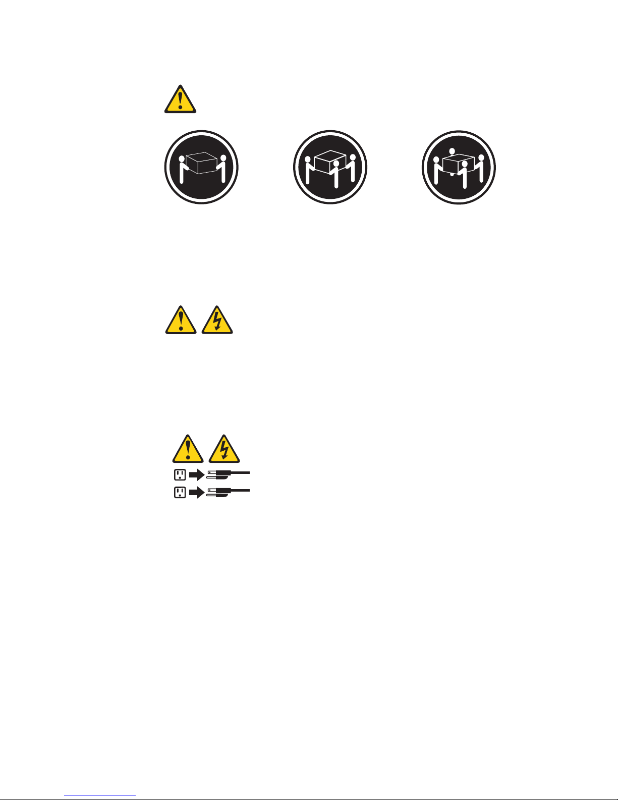
Statement 4:
≥ 18 kg (39.7 lb.) ≥ 32 kg (70.5 lb.) ≥ 55 kg (121.2 lb.)
CAUTION:
Use safe practices when lifting.
Statement 5:
CAUTION:
The power control button on the device and the power switch on the power
supply do not turn off the electrical current supplied to the device. The device
also might have more than one power cord. To remove all electrical current
from the device, ensure that all power cords are disconnected from the power
source.
2
1
x IBM System x3550 Type 7978: User’s Guide
Page 13
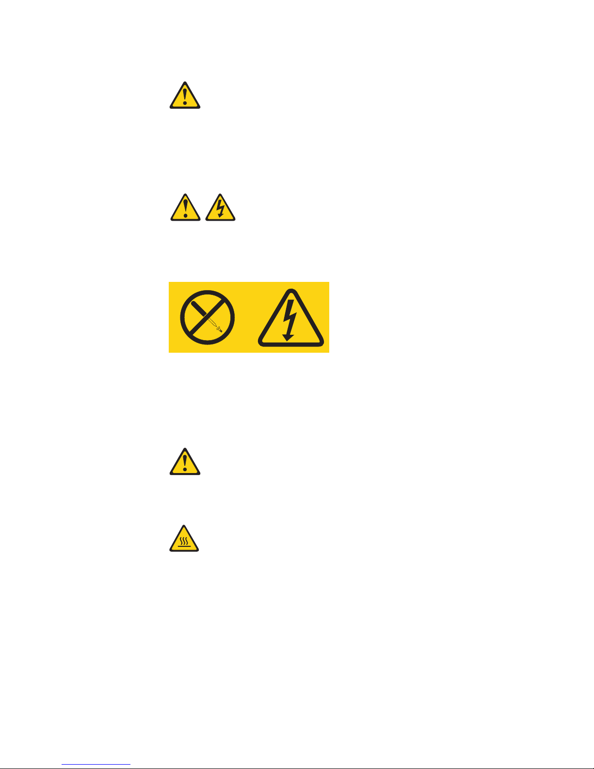
Statement 6:
CAUTION:
Do not place any objects on top of a rack-mounted device unless that
rack-mounted device is intended for use as a shelf.
Statement 8:
CAUTION:
Never remove the cover on a power supply or any part that has the following
label attached.
Hazardous voltage, current, and energy levels are present inside any
component that has this label attached. There are no serviceable parts inside
these components. If you suspect a problem with one of these parts, contact
a service technician.
Statement 12:
CAUTION:
The following label indicates a hot surface nearby.
Safety xi
Page 14
Statement 26:
CAUTION:
Do not place any object on top of rack-mounted devices.
xii IBM System x3550 Type 7978: User’s Guide
Page 15
Chapter 1. The System x3550 Type 7978 server
®
The IBM
high-volume network transaction processing. This high-performance, dual core
server is ideally suited for networking environments that require superior
microprocessor performance, input/output (I/O) flexibility, and high manageability.
The System x3550 server supports one of the following hard disk drive
configurations:
v Servers with four hot-swap bays support 2.5-inch hot-swap Serial Attached SCSI
(SAS) hard disk drives. You can install only 2.5-inch hot-swap SAS drives in
these servers.
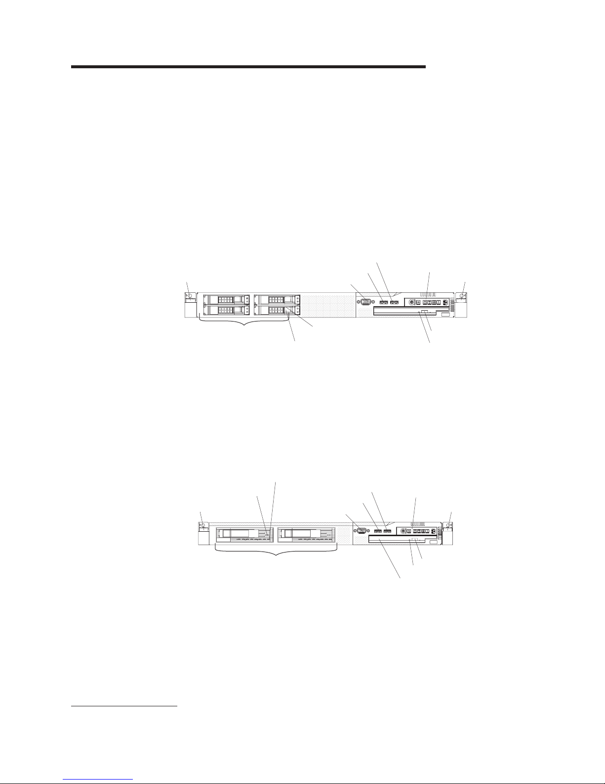
The following illustration shows a System x3550 server with a 2.5-inch hard disk
drive configuration.
Rack release latch
System x3550 Type 7978 server is a 1-U-high
USB 3 connector
USB 4 connector
Video connector
1
rack model server for
Operator information
panel
Rack release latch
2.5-inch hard disk drives
Hard disk drive
status LED
Hard disk drive
activity LED
CD-RW/DVD eject button
CD-RW/DVD drive activity LED
v Servers with two hot-swap bays support 3.5-inch hot-swap SAS or 3.5-inch
hot-swap Serial ATA (SATA) hard disk drives. Yo u can install only 3.5-inch
hot-swap SAS or hot-swap SATA drives in these servers.
v Servers with two simple-swap bays support 3.5-inch simple-swap SATA hard disk
drives. Yo u can install only 3.5-inch simple-swap SATA drives in these servers.
The following illustration shows a System x3550 server with a hot-swap or
simple-swap 3.5-inch hard disk drive configuration.
Hard disk
drive status
Rack release latch
3.5 inch hard disk drives
Hard disk
drive activity
USB 3 connector
USB 4 connector
Video connector
Operator information panel
Rack release latch
CD-RW/DVD eject button
CD-RW/DVD drive activity LED
CD-RW/DVD drive
Performance, ease of use, reliability, and expansion capabilities were key
considerations in the design of the server. These design features make it possible
for you to customize the system hardware to meet your needs today and provide
flexible expansion capabilities for the future.
1. Racks are marked in vertical increments of 1.75 inches each. Each increment is referred to as a unit, or a “U”. A 1-U-high device
is approximately 1.75 inches tall.
© Copyright IBM Corp. 2006 1
Page 16

The server comes with a limited warranty. For information about the terms of the
warranty and getting service and assistance, see the Warranty and Support
Information document.
The server contains IBM Enterprise X-Architecture
increase performance and reliability. For more information, see “What your server
offers” on page 6 and “Reliability, availability, and serviceability” on page 8.
You can obtain up-to-date information about the server and other IBM server
products at http://www.ibm.com/systems/x/.
Related documentation
This User’s Guide provides general information about the server, including how to
install supported options and how to configure the server. The following
documentation also comes with the server:
v Installation Guide
This printed document contains instructions for setting up the server and basic
instructions for installing some options.
v Safety Information
This document is in Portable Document Format (PDF) on the IBM System x
Documentation CD. It contains translated caution and danger statements. Each
caution and danger statement that appears in the documentation has a number
that you can use to locate the corresponding statement in your language in the
Safety Information document.
v Rack Installation Instructions
This printed document contains instructions for installing the server in a rack.
v Problem Determination and Service Guide
This document is in PDF on the IBM System x Documentation CD. It contains
information to help you solve problems yourself, and it contains information for
service technicians.
v Warranty and Support Information
This document is in PDF on the IBM System x Documentation CD. It contains
information about the terms of the warranty and getting service and assistance.
™
technologies, which help
Depending
IBM System x Documentation CD.
The xSeries Tools Center is an online information center that contains information
about tools for updating, managing, and deploying firmware, device drivers, and
operating systems. The xSeries Tools Center is at http://publib.boulder.ibm.com/
infocenter/toolsctr/v1r0/index.jsp.
The server might have features that are not described in the documentation that
you received with the server. The documentation might be updated occasionally to
include information about those features, or technical updates might be available to
provide additional information that is not included in the server documentation.
These updates are available from the IBM Web site. To check for updates, go to
http://www.ibm.com/servers/eserver/support/xseries/index.html, select System
x3550 from the Hardware list, and click Go. For firmware updates, click the
Download tab. For Documentation updates, click the Install and use tab, and click
Product documentation.
2 IBM System x3550 Type 7978: User’s Guide
on the server model, additional documentation might be included on the
Page 17

Notices and statements used in this document
The caution and danger statements that appear in this document are also in the
multilingual Safety Information document, which is on the IBM System x
Documentation CD. Each statement is numbered for reference to the corresponding
statement in the Safety Information document.
The following notices and statements are used in this document:
v Note: These notices provide important tips, guidance, or advice.
v Important: These notices provide information or advice that might help you avoid
inconvenient or problem situations.
v Attention: These notices indicate potential damage to programs, devices, or
data. An attention notice is placed just before the instruction or situation in which
damage could occur.
v Caution: These statements indicate situations that can be potentially hazardous
to you. A caution statement is placed just before the description of a potentially
hazardous procedure step or situation.
v Danger: These statements indicate situations that can be potentially lethal or
extremely hazardous to you. A danger statement is placed just before the
description of a potentially lethal or extremely hazardous procedure step or
situation.
Chapter 1. The System x3550 Type 7978 server 3
Page 18

Features and specifications
The following information is a summary of the features and specifications of the
server. Depending on the form factor server, some features might not be available,
or some specifications might not apply.
4 IBM System x3550 Type 7978: User’s Guide
Page 19

Table 1. Features and specifications
Microprocessor:
®
™
v Intel
Xeon
FC-LGA 771
dual-core with 4096 KB (minimum)
Level-2 cache
v Support for up to two
microprocessors
v Support for Intel Extended Memory
64 Technology (EM64T)
Note:
v Use the Configuration/Setup Utility
program to determine the type and
speed of the microprocessors.
v For a list of supported
microprocessors, see
http://www.ibm.com/servers/eserver/
serverproven/compat/us/
Memory:
v Minimum: 1 GB
v Maximum: 32 GB
v Type: PC2-5300, 667 MHz, ECC,
DDR II fully buffered SDRAM
DIMMs only
v Slots: Eight dual inline
v Supports 512 MB, 1 GB, 2 GB, and
4 GB (when available) DIMMs
Drives:
CD/DVD: IDE 24x CD-RW/ 8x DVD
combination
Expansion bays (depending on
model):
Either two 3.5-inch or four 2.5-inch
hard disk drive bays
v Servers with a 2.5-inch hot-swap
drive bay configuration support up
to four 2.5-inch hot-swap SAS hard
disk drives
v Servers with a 3.5-inch hot-swap
drive bay configuration support up
to two 3.5-inch SAS or SATA
hot-swap hard disk drives
v Servers with a 3.5-inch
simple-swap drive bay configuration
support up to two 3.5-inch
simple-swap SATA hard disk drives
PCI
Expansion slots:
v One PCI Express x8 (half length)
v One PCI Express x8 (half length) or
PCI-X (half length)
Power supply:
Maximum of two redundant 670-watt
(110 or 220 V ac auto-sensing)
hot-swap power supplies.
Hot-swap fans:
v Standard: five
v Maximum: six (with two
microprocessors installed)
Size:
v Height: 43 mm (1.69 inches, 1 U)
v Depth: 711 mm (28 inches)
v Width: 440 mm (17.3 inches)
v Maximum weight: 15.4 kg (34 lb)
when fully configured
Integrated
functions:
v Tw o Broadcom NetXtreme II Gb
Ethernet controllers with TOE and
Wake on LAN
®
support
v Four Universal Serial Bus (USB)
2.0 ports (two front and two rear)
v One Advanced System
Management RJ-45 (active only
when a Remote Supervisor
Adapter II SlimLine is installed)
v One serial port
Hard
disk controllers:
v Serial ATA (SATA) controller with
integrated RAID (simple-swap
SATA models)
v Serial-attached SCSI (SAS)
controller with integrated RAID
(hot-swap SAS models)
Acoustical
noise emissions:
v Sound power, idling: 6.8 bels
maximum
v Sound power, operating: 6.8 bels
maximum
Environment:
v Air temperature:
– Server on: 10° to 35°C (50.0°
to 95.0°F); altitude: 0 to 914 m
(2998.7 ft)
– Server off: -40° to 60°C
(-104° to 140°F); maximum
altitude: 2133 m (6998.0 ft)
v
Humidity:
– Server on: 8% to 80%
– Server off: 8% to 80%
Heat output:
Approximate heat output in British
thermal units (Btu) per hour:
v Minimum configuration: 662 Btu per
hour (194 watts)
v Maximum configuration: 2390 Btu
per hour (700 watts)
Electrical
input:
v Sine-wave input (47-63 Hz) required
v Input voltage low range:
– Minimum: 100 V ac
– Maximum: 127 V ac
v
Input voltage high range:
– Minimum: 200 V ac
– Maximum: 240 V ac
v
Input kilovolt-amperes (kVA),
approximately:
– Minimum: 0.194 kVA
– Maximum: 0.700 kVA
Video
controller (integrated):
v AT I Radeon RN50 (dual ports - front
and rear)
v Support for SPI Serial flash memory
video BIOS
v Flexible memory support
– 8 MB to 256 MB
– DDR1 and DDR2 SDRAM and
SGRAM
Notes:
1. Power consumption and heat
output vary depending on the
number and type of optional
features installed and the
power-management optional
features in use.
2. These levels were measured in
controlled acoustical environments
according to the procedures
specified by the American National
Standards Institute (ANSI) S12.10
and ISO 7779 and are reported in
accordance with ISO 9296. Actual
sound-pressure levels in a given
location might exceed the average
values stated because of room
reflections and other nearby noise
sources. The declared sound-power
levels indicate an upper limit, below
which a large number of computers
will operate.
Chapter 1. The System x3550 Type 7978 server 5
Page 20

What your server offers
The server uses the following features and technologies:
v Advanced System Management
The Remote Supervisor Adapter II Slimline provides Advanced System
Management capabilities by enabling remote keyboard, video, and mouse (KVM)
access to the server.
v Baseboard management controller
The baseboard management controller (BMC) provides basic service-processor
environmental monitoring functions. If an environmental condition exceeds a
threshold or if a system component fails, the baseboard management controller
lights LEDs to help you diagnose the problem. Critical errors are included in the
error log. The BMC also provides Serial over LAN (SOL) connectivity.
v Diagnostics program
You can use the diagnostics program to test the major components of the server.
To start the diagnostics program, press F2 while the server is starting.
v Dual-core processing
The server supports up to two Intel microprocessors. The server comes with only
one microprocessor, and you can install a second microprocessor to enhance
performance.
v IBM Director
IBM Director is a workgroup-hardware-management tool that you can use to
centrally manage System x servers. For more information, see the IBM Director
documentation on the IBM Director CD.
v IBM Enterprise X-Architecture technology
IBM X-Architecture technology combines proven, innovative IBM designs to make
your Intel-processor-based server powerful, scalable, and reliable. For more
information, see http://www.ibm.com/servers/eserver/xseries/xarchitecture/
enterprise/html.
– Active
The Active Memory feature improves the reliability of memory through memory
mirroring and online-spare memory. Memory mirroring stores data in two pairs
of DIMMs simultaneously. Online-spare memory disables a failed pair of
DIMMs from the system configuration and activates a pair of online-spare
DIMMs. For more information, see the section about installing DIMMs in the
Installation Guide.
– Large system-memory capacity
The memory bus supports up to 32 GB of system memory. The memory
controller supports error correcting code (ECC) for up to eight
industry-standard PC2-5300, 667 MHz, DDR2 (second-generation
double-data-rate), fully buffered, synchronous dynamic random access
memory (SDRAM) dual inline memory modules (DIMMs).
IBM ServerGuide
v
The ServerGuide Setup and Installation CD that comes with the server provides
programs to help you set up the server and install a Windows
The ServerGuide program detects installed hardware options and provides the
correct configuration programs and device drivers. For more information about
the ServerGuide Setup and Installation CD, see “Using the ServerGuide Setup
and Installation CD” on page 56.
v Integrated network support
™
Memory
™
Setup and Installation CD
®
operating system.
6 IBM System x3550 Type 7978: User’s Guide
Page 21

The server comes with an integrated dual port Broadcom Gigabit Ethernet
controller, which supports connection to a 10-Mbps, 100-Mbps, or 1000-Mbps
network. For more information, see “Configuring the Gigabit Ethernet controller”
on page 70.
v Large data-storage capacity and hot-swap capability
The server supports a maximum of four 2.5-inch or two 3.5-inch Serial Attached
SCSI (SAS) or Serial ATA (SATA) hot-swap hard disk drives in the hot-swap bays
or two 3.5-inch S ATA simple swap hard disk drives.
With the hot-swap feature, you can add, remove, or replace hard disk drives
without turning off the server.
v Light path diagnostics
Light path diagnostics provides LEDs to help you diagnose problems. For more
information, see the section about light path diagnostics in the Installation Guide.
v PCI adapter capabilities
The server has two half-length PCI interface slots. Both slots can be used for
PCI Express adapters. The full-length slot can be used for either a PCI-X adapter
or a PCI Express adapter.
v PowerExecutive
PowerExecutive is an IBM Director extension that measures and reports server
power consumption as it occurs. This enables you to monitor power consumption
in correlation to specific software application programs and hardware
systems-management interface, and can view them using IBM Director. For more
information, including the required levels of IBM Director and PowerExecutive,
see the IBM Director documentation on the IBM Director CD, or see
www.ibm.com/servers/eserver/xseries/systems_management/ibm_director/
extensions.
v Redundant connection
The addition of an optional network interface card (NIC) provides failover
capability to a redundant Ethernet connection. If a problem occurs with the
primary Ethernet connection, all Ethernet traffic that is associated with the
primary connection is automatically switched to the redundant NIC. If the
applicable device drivers are installed, this switching occurs without data loss and
without user intervention.
v Redundant cooling and optional power capabilities
The server supports a maximum of two 670-watt hot-swap power supplies and
six hot-swap fans, which provide redundancy and hot-swap capability for a typical
configuration.The redundant cooling of the fans in the server enables continued
operation if one of the fans fails. The server comes with one 670-watt hot-swap
power supply and five fans. Yo u can order the second optional power supply with
the additional fan.
™
v ServeRAID
support
An optional ServeRAID adapter provides hardware redundant array of
independent disks (RAID) support to create configurations. The standard RAID
configuration on the server provides software RAID support and mirroring.
v Systems-management capabilities
The server comes with a baseboard management controller (BMC). When the
BMC is used with the systems-management software that comes with the server,
you can manage the functions of the server locally and remotely. The BMC also
provides system monitoring, event recording, and network alert capability.
The optional Remote Supervisor Adapter II SlimLine can be used to obtain
enhanced systems-management capabilities, in addition to those of the
Chapter 1. The System x3550 Type 7978 server 7
Page 22

embedded BMC. The Remote Supervisor Adapter II SlimLine, provides a
dedicated Ethernet connection at the rear of the server.
v TCP/IP offload engine (RTOE) support
The Ethernet controllers in the server support TOE, which is a technology that
offloads the TCP/IP flow from the microprocessor and I/O subsystem to increase
the speed of the TCP/IP flow. When an operating system that supports TOE is
running on the server and TOE is enabled, the server supports TOE operation.
See the operating-system documentation for information about enabling TOE.
Note: As of the date of this document, the Linux operating system does not
support TOE.
Reliability, availability, and serviceability
Three important computer design features are reliability, availability, and
serviceability (RAS). The RAS features help to ensure the integrity of the data that
is stored in the server, the availability of the server when you need it, and the ease
with which you can diagnose and correct problems.
Your server has the following RAS features:
v Automatic error retry and recovery
v Automatic restart after a power failure
v Baseboard management controller (BMC) service processor
v Backup basic input/output system (BIOS) switching under the control of the BMC
v Built-in monitoring for fan, power, temperature, voltage, and power-supply
redundancy
v Cable-presence detection on most connectors
v Chipkill
v Error codes and messages
v Error correcting code (ECC) L2 cache and system memory
v Hot-swap hard disk drives, some drives
v Information and light path diagnostics LED panels
v Menu-driven setup, system configuration, and redundant array of independent
disks (RAID) configuration programs
v Availability of microcode and diagnostic levels
v Parity checking on the small computer system interface (SCSI) bus and PCI
buses
v Power management: Compliance with Advanced Configuration and Power
Interface (ACPI)
v Power-on self-test (POST)
v Predictive Failure Analysis
v Redundant Ethernet capabilities with failover support
v Hot-swap cooling fans with speed-sensing capability
v Redundant hot-swap power supplies and redundant hot-swap fans (some
models)
v Remind button to temporarily turn off the system-error LED
v Remote system problem-determination support
v Standby voltage for system-management features and monitoring
v Startup (boot) from LAN through remote initial program load (RIPL) or dynamic
host configuration protocol/boot protocol (DHCP/BOOTP)
v System auto-configuring from the configuration menu
v System-error logging (POST and BMC)
v System-management monitoring through the Iner IC protocol
v Upgradeable POST, BIOS, diagnostics, BMC firmware, and read-only memory
(ROM) resident code, locally or over the LAN
™
memory protection
®
(PFA) alerts
8 IBM System x3550 Type 7978: User’s Guide
Page 23

IBM Director
v Vital product data (VPD) on microprocessors, system board, power supplies,
SAS (hot-swap-drive) backplane, and power backplane
v Wake on LAN feature capability
With IBM Director, a network administrator can perform the following tasks:
v View the hardware configuration of remote systems, in detail
v Monitor the usage and performance of critical components, such as
microprocessors, disks, and memory
v Centrally manage individual or large groups of IBM and non-IBM
Intel-processor-based servers, desktop computers, workstations, and mobile
computers on a variety of platforms
Director provides a comprehensive entry-level workgroup hardware manager. It
IBM
includes the following key features:
v Advanced self-management capabilities for maximum system availability.
®
v Multiple operating-system platform support, including Microsoft
Windows 2000
Server, Windows Server 2003, Windows XP Professional, AIX, i5/OS, Red Hat
Linux, SUSE Linux, VMware, and Novell NetWare. For a complete list of
operating systems that support IBM Director, see the IBM Director Compatibility
Document. This document is in Portable Document Format (PDF) at
http://www.ibm.com/pc/support/site.wss/document.do?lndocid=MIGR-61788. It is
updated every 6 to 8 weeks.
v Support for IBM and non-IBM servers, desktop computers, workstations, and
mobile computers.
v Support for systems-management industry standards.
v Integration into leading workgroup and enterprise systems-management
environments.
v Ease of use, training, and setup.
Director also provides an extensible platform that supports advanced server
IBM
tools that are designed to reduce the total cost of managing and supporting
networked systems. By deploying IBM Director, you can achieve reductions in
ownership costs through the following benefits:
v Reduced downtime
v Increased productivity of IT personnel and users
v Reduced service and support costs
more information about IBM Director, see the documentation on the IBM
For
Director CD that comes with the server, the IBM Director Information Center at
http://publib.boulder.ibm.com/infocenter/eserver/v1r2/topic/diricinfo/ fqm0_main.html,
and the IBM System x Systems Management Web page at http://www.ibm.com/
servers/systems/x/systems_management/,
Systems Management and IBM Director.
The UpdateXpress program
The UpdateXpress program is available for most servers and server options. It
detects supported and installed device drivers and firmware in the server and
installs available updates. Yo u can download the UpdateXpress program from the
Web at no additional cost, or you can purchase it on a CD. To download the
which presents an overview of IBM
Chapter 1. The System x3550 Type 7978 server 9
Page 24
program or purchase the CD, go to http://www.ibm.com/systems/x/
systems_management/ ibm_director/extensions/xpress.html.
Server controls, LEDs, and power
This section describes the controls and light-emitting diodes (LEDs) and how to turn
the server on and off.
Front view
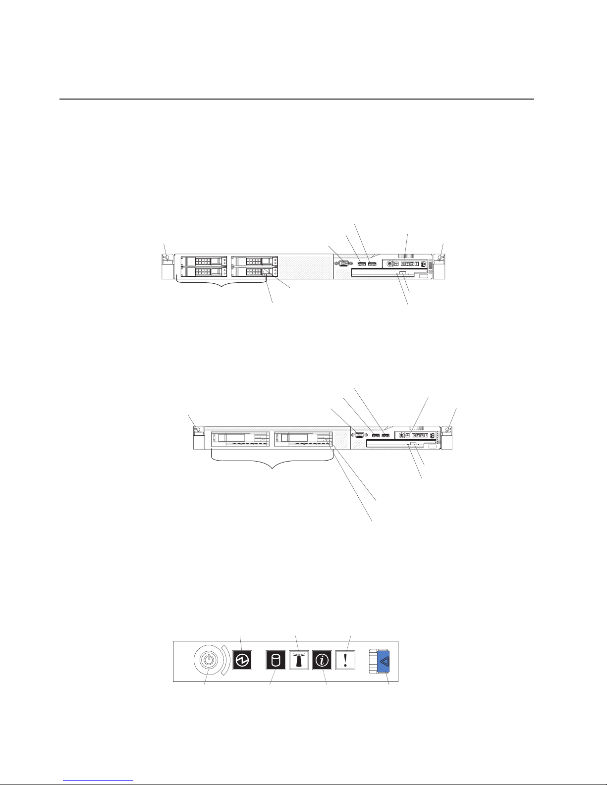
The following illustration shows the controls, LEDs, and connectors on the front of
the server. This configuration supports up to four 2.5-inch hot-swappable hard disk
drives.
Rack release latch
Video connector
USB 3 connector
USB 4 connector
Operator information
panel
Rack release latch
2.5-inch hard disk drives
Hard disk drive
status LED
Hard disk drive
activity LED
CD-RW/DVD eject button
CD-RW/DVD drive activity LED
The following illustration shows the controls, LEDs, and connectors on the front of
the server. This configuration supports up to two 3.5-inch hot-swappable hard disk
drives or two 3.5-inch simple-swap SATA hard disk drives.
Rack release latch
3.5-inch hard disk drives
USB 3 connector
USB 4 connector
Video connector
Operator information panel
Rack release latch
CD-RW/DVD eject button
CD-RW/DVD drive
activity LED
Hard disk drive
status LED (SAS model)
Hard disk drive
activity LED (SAS model)
Note: The locations of the controls, LEDs, and connectors vary, depending on the
hardware configuration that you have.
v Operator information panel: This panel contains controls and LEDs about the
status of the server.
Power-on
LED (green)
System
locator
LED (blue)
System-error
LED (amber)
Powercontrol
button
10 IBM System x3550 Type 7978: User’s Guide
Hard drive
activity
LED (green)
System
information
LED (amber)
Release
latch
Page 25

The following controls and LEDs are on the operator information panel:
– Power-on LED: When this green LED is lit and not flashing, it indicates that
the server is turned on. When this LED is flashing, it indicates that the server
is turned off and is still connected to an ac power source. When this LED is
off, it indicates that ac power is not present, or the power supply or the LED
itself has failed. A power LED is also on the rear of the server.
Note: If this LED is off, it does not mean that there is no electrical power in
the server. The LED might be burned out. To remove all electrical
power from the server, you must disconnect the power cord from the
electrical outlet.
– System-locator LED: Use this blue LED to visually locate the server among
other servers. You can use IBM Director to light this LED remotely. This LED
is controlled by the BMC.
– System-error LED: When this amber LED is lit, it indicates that a system
error has occurred. A system-error LED is also on the rear of the server. An
LED on the light path diagnostics panel on the system board is also lit to help
isolate the error. This LED is controlled by the BMC.
– Release latch: Press the release latch to the left to slide out the operator
information panel and view the light path diagnostics LEDs and buttons. See
the Problem Determination and Service Guide for more information about the
light path diagnostics panel.
– System-information LED: When this amber LED is lit, it indicates that a
noncritical event has occurred. Check the error log for additional information.
See the information about light path diagnostics in the Problem Determination
and Service Guide for more information about error logs.
– Hard drive activity LED: When this green LED is lit, it indicates that one of
the hard disk drives is in use.
Notes:
1. For a SAS drive, a hard disk drive activity LED is shown in two places: on
the hard disk drive and on the operator information panel.
2. For a S ATA drive, hard disk drive activity is indicated only by the hard disk
drive activity LED on the operator information panel.
– Power-control button: Press this button to turn the server on and off
manually.
v Rack release latches: Press the latches on each front side of the server to
remove the server from the rack.
v Video connector: Connect a monitor to this connector. The video connectors on
the front and rear of the server can be used simultaneously.
v USB connectors: Connect a USB device, such as a USB mouse, keyboard, or
other device to any of these connectors.
v CD-RW/DVD eject button: Press this button to release a DVD or CD from the
CD/DVD drive.
v CD-RW/DVD drive activity LED: When this LED is lit, it indicates that the
CD-RW/DVD drive is in use.
v Hard disk drive status LED: This LED is used on SAS hard disk drives. When
this LED is lit, it indicates that the drive has failed. If an optional IBM ServeRAID
controller is installed in the server, when this LED is flashing slowly (one flash
per second), it indicates that the drive is being rebuilt. When the LED is flashing
rapidly (three flashes per second), it indicates that the controller is identifying the
drive.
Chapter 1. The System x3550 Type 7978 server 11
Page 26
v Hard disk drive activity LED: This LED is used on SAS hard disk drives. Each
hot-swap hard disk drive has an activity LED, and when this LED is flashing, it
indicates that the drive is in use.
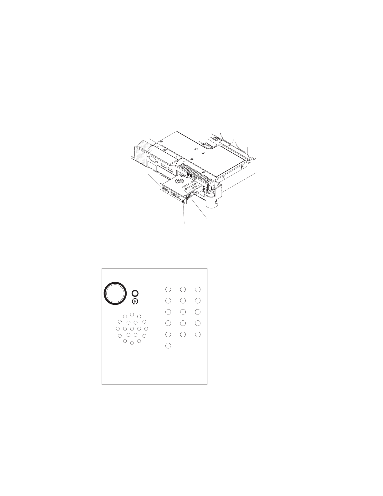
Light path diagnostics panel
The light path diagnostics panel is on the top of the operator information panel.
To access the light path diagnostics panel, push the release button on the operator
panel to the left. Pull forward on the unit until the hinge of the operator panel is free
of the server chassis. Then pull down on the unit, so that the operator information
panel is at a right angle with the server.
Operator information
panel
Light path LEDs
Release button
The following illustration shows the LEDs and controls on the light path diagnostics
panel.
Light Path
Diagnostics
CPU
MEM
FAN
PCI
PS1SPPS2
VRM
CNFG
NMI
S ERR
RAID
DASD
TEMP
BRD
OVER SPEC
REMIND
v Remind button: This button places the system-error LED on the front panel into
Remind mode. In Remind mode, the system-error LED flashes rapidly until the
problem is corrected, the system is restarted, or a new problem occurs.
By placing the system-error LED indicator in Remind mode, you acknowledge
that you are aware of the last failure but will not take immediate action to correct
the problem. The remind function is handled by the BMC.
v Reset button: Press this button to reset the server and run the power-on
self-test (POST). You might have to use a pen or the end of a straightened paper
clip to press the button. The reset button is to the right of the remind button.
12 IBM System x3550 Type 7978: User’s Guide
Page 27
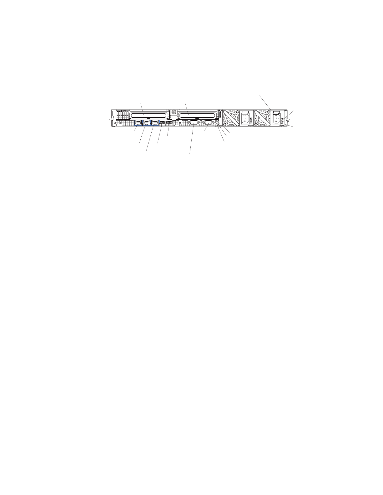
Rear view
For information about light path diagnostics, see the System x3550 Problem
Determination and Service Guide on the IBM System x Documentation CD.
The following illustration shows the connectors and LEDs on the rear of the server.
Ethernet 1
Ethernet 2
PCI slot 1 PCI slot 2
USB 2
USB 1
Systems
management
Ethernet connector
Serial
connector
Video
connector
Power connector
Power-on LED
System-locator LED
System-error LED
AC Power
LED
DC Power
LED
v PCI slot 1: Insert a PCI Express type adapter into this slot.
v PCI slot 2: Insert a PCI Express type adapter into this slot. Yo u can purchase an
optional PCI-X riser card assembly to convert this slot to accept a PCI-X adapter.
v Power connector: Connect the power cord to this connector.
v AC power LED: Each hot-swap power supply has an ac power LED and a dc
power LED. When the ac power LED is lit, it indicates that sufficient power is
coming into the power supply through the power cord. During typical operation,
both the ac and dc power LEDs are lit. For any other combination of LEDs, see
the Problem Determination and Service Guide on the IBM System x
Documentation CD.
v DC power LED: Each hot-swap power supply has a dc power LED and an ac
power LED. When the dc power LED is lit, it indicates that the power supply is
supplying adequate dc power to the system. During typical operation, both the ac
and dc power LEDs are lit. For any other combination of LEDs, see the Problem
Determination and Service Guide on the IBM System x Documentation CD.
v System-error LED: When this LED is lit, it indicates that a system error has
occurred. An LED on the light path diagnostics panel is also lit to help isolate the
error.
v Power-on LED: When this LED is lit and not flashing, it indicates that the server
is turned on. When this LED is flashing, it indicates that the server is turned off
and still connected to an ac power source. When this LED is off, it indicates that
ac power is not present, or the power supply or the LED itself has failed.
v System-locator LED: Use this LED to visually locate the server among other
servers. Yo u can use IBM Director to light this LED remotely.
v Video connector: Connect a monitor to this connector. The video connectors on
the front and rear of the server can be used simultaneously.
v Serial connector: Connect a 9-pin serial device to this connector. The serial port
is shared with the baseboard management controller (BMC). The BMC can take
control of the shared serial port to perform text console redirection and to redirect
serial traffic, using Serial over LAN (SOL).
v USB connectors: Connect a USB device, such as a USB mouse, keyboard, or
other device to any of these connectors.
v Systems-management Ethernet connector: Use this connector to connect the
server to a network for systems-management information control. This connector
is active only if you have installed a Remote Supervisor Adapter II SlimLine, and
it is used only by the Remote Supervisor Adapter II SlimLine.
Chapter 1. The System x3550 Type 7978 server 13
Page 28

v Ethernet activity LEDs: When these LEDs are lit, they indicate that the server is
transmitting to or receiving signals from the Ethernet LAN that is connected to
the Ethernet port. See “Connecting the cables” on page 46 for the LED location.
v Ethernet link LEDs: When these LEDs are lit, they indicate that there is an
active link connection on the 10BASE-T, 100BASE-TX, or 1000BASE-TX
interface for the Ethernet port. See “Connecting the cables” on page 46 for the
LED location.
v Ethernet connectors: Use either of these connectors to connect the server to a
network.
Server power features
When the server is connected to an ac power source but is not turned on, the
operating system does not run, and all core logic except for the service processor
(the baseboard management controller or optional Remote Supervisor Adapter II
SlimLine) is shutdown; however, the server can respond to requests from the
service processor, such as a remote request to turn on the server. The power-on
LED flashes to indicate that the server is connected to ac power but is not turned
on.
Turning on the server
Approximately 5 seconds after the server is connected to ac power, the
power-control button becomes active, and one or more fans might start running to
provide cooling while the server is connected to power. Yo u can turn on the server
and start the operating system by pressing the power-control button.
The server can also be turned on in any of the following ways:
v If a power failure occurs while the server is turned on, the server will restart
automatically when power is restored.
v If you installed an optional Remote Supervisor Adapter II SlimLine, the server can
be turned on from the Remote Supervisor Adapter II SlimLine user interface.
v If your operating system supports the Wake on LAN feature, the Wake on LAN
feature can turn on the server.
When 4 GB or more of memory (physical or logical) is installed, some
Note:
memory is reserved for various system resources and is unavailable to the
operating system. The amount of memory that is reserved for system
resources depends on the operating system, the configuration of the server,
and the configured PCI options.
Turning off the server
When you turn off the server and leave it connected to ac power, the server can
respond to requests from the service processor, such as a remote request to turn
on the server. While the server remains connected to ac power, one or more fans
might continue to run. To remove all power from the server, you must disconnect it
from the power source.
Some operating systems require an orderly shutdown before you turn off the server.
See your operating-system documentation for information about shutting down the
operating system.
14 IBM System x3550 Type 7978: User’s Guide
Page 29
Statement 5:
CAUTION:
The power control button on the device and the power switch on the power
supply do not turn off the electrical current supplied to the device. The device
also might have more than one power cord. To remove all electrical current
from the device, ensure that all power cords are disconnected from the power
source.
2
1
The server can be turned off in any of the following ways:
v You can turn off the server from the operating system, if your operating system
supports this feature. After an orderly shutdown of the operating system, the
server will turn off automatically.
v You can press the power-control button to start an orderly shutdown of the
operating system and turn off the server, if your operating system supports this
feature.
v If the operating system stops functioning, you can press and hold the
power-control button for more than 4 seconds to turn off the server.
v If you installed an optional Remote Supervisor Adapter II SlimLine, the server can
be turned off from the Remote Supervisor Adapter II SlimLine user interface.
v The baseboard management controller can turn off the server as an automatic
response to a critical system failure.
Chapter 1. The System x3550 Type 7978 server 15
Page 30

16 IBM System x3550 Type 7978: User’s Guide
Page 31

Chapter 2. Installing options
This chapter provides detailed instructions for installing optional hardware devices in
the server.
Server components
The following illustration shows the major components in the server. The
illustrations in this document might differ slightly from your hardware.
SATA backplate
3.5-inch hard disk drive cage
3.5-inch SAS hard disk drive
3.5-inch SATA hard disk drive
3.5-inch filler panel
(simple-swap)
3.5-inch filler panel (hot-swap)
2.5-inch hard disk drive backplane
2.5-inch hard disk drive cage
2.5-inch
filler panel
(hot-swap)
SAS backplane
2.5-inch
hard disk drive
Air baffle
Powe r
backplane
Microprocessor
Cover
Microprocessor
heatsink
Air baffle
DIMM
ServeRAID
SAS controller
PCI-X riser card
PCI Express
riser card
System board
Power supply
Power-supply filler
Fans (1, 2)
© Copyright IBM Corp. 2006 17
Fans (3 - 6)
CD-RW/DVD drive
Operator information panel
Page 32
System-board internal connectors
The following illustration shows the internal connectors on the system board.
SAS signal
connector (J65)
(some models)
SATA 1 signal
connector (port 1)
(some models)
Power supply
backplane
connector
Microprocessor 1
connector
SATA 0 signal
connector (port 0)
(some models)
CD-RW/DVD connector
Operator information
panel connector
Video front panel
connector
USB front panel
connector
(USB3 and USB4)
18 IBM System x3550 Type 7978: User’s Guide
Page 33

System-board external connectors
The following illustration shows the external input/output connectors on the system
board.
USB 1 connector
USB 2 connector
Serial connector
Video connector
Ethernet connector
Systems- management
Ethernet 2 connector
Ethernet 1 connector
Chapter 2. Installing options 19
Page 34

System-board switches and jumpers
The following illustration shows the switches and jumpers on the system board.
1
2
3
Boot block recovery
jumper (J14)
8 7 6 5 4 3 2 1
ON
System board switch
block (SW2)
NMI (SW1)
20 IBM System x3550 Type 7978: User’s Guide
Page 35

System-board LEDs
The following illustration shows the light-emitting diodes (LEDs) on the system
board.
Power-on LED
Location LED
System-error LED
PCI slot 2 error LED
Remote Supervisor
Adapter II
SlimLine error LED
BMC status
LED
System-board
fault LED
System-board battery
error LED
PCI slot 1
error LED
DIMM 5 error LED
DIMM 6 error LED
DIMM 7 error LED
DIMM 8 error LED
Light path diagnostics
active LED
Light path diagnostics switch
RAID error LED
Microprocessor 2
error LED
Microprocessor 1
error LED
Fan 1 error LED
Power B error LED
Power A error LED
Power C error LED
Power D error LED
Fan 2 error LED
DIMM 1 error LED
DIMM 2 error LED
DIMM 3 error LED
DIMM 4 error LED
Fan 6 error LED
Fan 5 error LED
Fan 4 error LED
Fan 3 error LED
Chapter 2. Installing options 21
Page 36

System-board channels and baffles
The following illustration shows how to route the cables for optional devices. The
illustration also shows where the two air baffles are located. For some devices, you
might have to remove the baffles to correctly route the cables.
22 IBM System x3550 Type 7978: User’s Guide
with cable guide
Air baffleAir baffle
Page 37

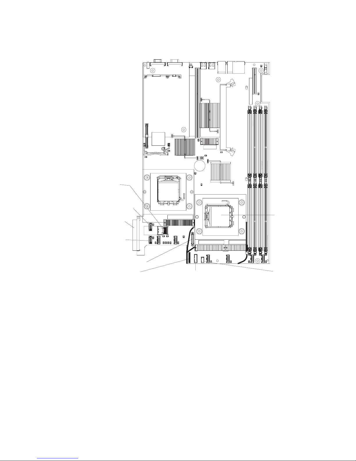
System-board option connectors
The following illustration shows the connectors on the system board for
user-installable options.
Remote Supervisor
Adapter II SlimLine
connector (J60)
Microprocessor 2
connector
Fan 1 connector
PCI Express or
PCI-X riser-card
connector slot 2
(J12)
PCI-Express
riser card connector slot 1
(J34)
RAID controller
connector (J3)
(some models)
DIMM 5 connector
DIMM 6 connector
DIMM 7 connector
DIMM 8 connector
DIMM 1 connector
DIMM 2 connector
DIMM 3 connector
DIMM 4 connector
Installation guidelines
Before you install options, read the following information:
v Read the safety information that begins on page v and the guidelines in
“Handling static-sensitive devices” on page 25. This information will help you
work safely.
v Observe good housekeeping in the area where you are working. Place removed
covers and other parts in a safe place.
v If you must start the server while the server cover is removed, make sure that no
one is near the server and that no tools or other objects have been left inside the
server.
v Do not attempt to lift an object that you think is too heavy for you. If you have to
lift a heavy object, observe the following precautions:
– Make sure that you can stand safely without slipping.
– Distribute the weight of the object equally between your feet.
– Use a slow lifting force. Never move suddenly or twist when you lift a heavy
object.
– To avoid straining the muscles in your back, lift by standing or by pushing up
with your leg muscles.
v Make sure that you have an adequate number of properly grounded electrical
outlets for the server, monitor, and other devices.
Chapter 2. Installing options 23
Page 38

v Back up all important data before you make changes to disk drives.
v Have a small flat-blade and a small Phillips head screwdriver available.
v You do not have to turn off the server to install or replace hot-swap power
supplies, hot-swap fans, or hot-plug Universal Serial Bus (USB) devices.
However, you must turn off the server before performing any steps that involve
removing or installing adapter cables.
v Blue on a component indicates touch points, where you can grip the component
to remove it from or install it in the server, open or close a latch, and so on.
v Orange on a component or an orange label on or near a component indicates
that the component can be hot-swapped, which means that if the server and
operating system support hot-swap capability, you can remove or install the
component while the server is running. (Orange can also indicate touch points on
hot-swap components.) See the instructions for removing or installing a specific
hot-swap component for any additional procedures that you might have to
perform before you remove or install the component.
v For a list of supported options for the server, see http://www.ibm.com/servers/
eserver/serverproven/compat/us/.
System reliability guidelines
To help ensure proper system cooling and system reliability, make sure that the
following requirements are met:
v Each of the drive bays has a drive or a filler panel and electromagnetic
compatibility (EMC) shield installed in it.
v If the server has redundant power, each of the power-supply bays has a power
supply installed in it.
v There is adequate space around the server to allow the server cooling system to
work properly. Leave approximately 50 mm (2.0 in.) of open space around the
front and rear of the server. Do not place objects in front of the fans. For proper
cooling and airflow, replace the server cover before turning on the server.
v You have followed the cabling instructions that come with optional adapters.
v You have replaced a failed fan within 48 hours.
v You have replaced a hot-swap drive within 2 minutes of removal.
v You do not operate the server without the air baffle installed. Operating the
server without the air baffle might cause the microprocessor to overheat.
v Microprocessor socket 2 always contains either a microprocessor baffle or a
microprocessor and heat sink.
Working inside the server with the power on
Attention: Static electricity that is released to internal server components when
the server is powered-on might cause the server to halt, which could result in the
loss of data. To avoid this potential problem, always use an electrostatic-discharge
wrist strap or other grounding system when working inside the server with the
power on.
The server supports hot-plug, hot-add, and hot-swap devices and is designed to
operate safely while it is turned on and the server cover is removed. Follow these
guidelines when you work inside a server that is turned on:
v Avoid wearing loose-fitting clothing on your forearms. Button long-sleeved shirts
before working inside the server; do not wear cuff links while you are working
inside the server.
v Do not allow your necktie or scarf to hang inside the server.
24 IBM System x3550 Type 7978: User’s Guide
Page 39

v Remove jewelry, such as bracelets, necklaces, rings, and loose-fitting wrist
watches.
v Remove items from your shirt pocket, such as pens and pencils, that could fall
into the server as you lean over it.
v Avoid dropping any metallic objects, such as paper clips, hairpins, and screws,
into the server.
Handling static-sensitive devices
Attention: Static electricity can damage the server and other electronic devices.
To avoid damage, keep static-sensitive devices in their static-protective packages
until you are ready to install them.
To reduce the possibility of damage from electrostatic discharge, observe the
following precautions:
v Limit your movement. Movement can cause static electricity to build up around
you.
v The use of a grounding system is recommended. For example, wear an
electrostatic-discharge wrist strap, if one is available. Always use an
electrostatic-discharge wrist strap or other grounding system when working inside
the server with the power on.
v Handle the device carefully, holding it by its edges or its frame.
v Do not touch solder joints, pins, or exposed circuitry.
v Do not leave the device where others can handle and damage it.
v While the device is still in its static-protective package, touch it to an unpainted
metal surface on the outside of the server for at least 2 seconds. This drains
static electricity from the package and from your body.
v Remove the device from its package and install it directly into the server without
setting down the device. If it is necessary to set down the device, put it back into
its static-protective package. Do not place the device on the server cover or on a
metal surface.
v Take additional care when handling devices during cold weather. Heating reduces
indoor humidity and increases static electricity.
Removing the server cover
Important: Before you install optional hardware, make sure that the server is
working correctly. Start the server, and make sure that the operating system starts,
if an operating system is installed, or that a 19990305 error code is displayed,
indicating that an operating system was not found but the server is otherwise
working correctly. If the server is not working correctly, see the Problem
Determination and Service Guide for diagnostic information.
To remove the server cover, complete the following steps:
1. Read the safety information that begins on page v and “Installation guidelines”
on page 23.
2. If you are planning on removing or installing a microprocessor, memory module,
PCI adapter, Remote SlimLine Adapter ll, RAID controller, simple-swap hard
disk drive, or battery, turn off the server and peripheral devices and disconnect
the power cords and all external cables, if necessary.
Chapter 2. Installing options 25
Page 40

Thumbscrew
Fan door
3. If the server has been installed in a rack, slide the server out from the rack
enclosure. See the Rack Installation Instructions that come with the server for
information about removing the server from the rack.
4. Slide and lift the two cover-release latches on the fan door on the right side of
the top of the server.
5. Lift the fan door cover.
6. Loosen the thumbscrew at the back of the server.
7. Slide the server cover back until the locking tabs release.
8. Lift the server cover off the server and set the server cover aside.
Attention: For proper cooling and airflow, replace the server cover before you
turn on the server.
Removing air baffles
There are two air baffles inside the server. These air baffles direct air to cool
components inside the server. Yo u might have to remove these baffles to access
certain components or connectors on the system board such as DIMMs, IDE
cables, or microprocessors.
To remove an air baffle, complete the following steps:
1. Read the safety information that begins on page v and “Installation guidelines”
on page 23.
2. Turn off the server and peripheral devices and disconnect the power cords and
all external cables, if necessary; then, remove the server cover.
3. To remove the air baffle that is closest to the wall of the server, complete these
steps:
26 IBM System x3550 Type 7978: User’s Guide
Page 41

Baffle
Tabs
Baffle pin
Baffle mounting
hole
a. Slide the baffle back from the front of the server to disengage the tab at the
front of the baffle from the bulkhead that runs the width of the server.
b. Lift the baffle up, making sure that the pins come out of the holes on the
system board.
Attention: For proper cooling and airflow, replace the air baffle before you
turn on the server. Operating the server with the air baffle removed might
damage server components.
Chapter 2. Installing options 27
Page 42

4. To remove the air baffle near the center of the server, complete these steps:
Air baffle
Cable routing slot
Baffle pins
Baffle mounting
holes
a. Slide the baffle back from the front of the server to disengage the tab at the
front of the baffle from the bulkhead that runs the width of the server.
b. Lift the baffle up slightly, making sure that the pins come out of the holes on
the system board.
c. Slide the cables out of the cable routing slot. Make sure you do not
disconnect or loosen the cables.
d. Lift the baffle out completely.
Attention: For proper cooling and airflow, replace the air baffle before you turn on
the server. Operating the server with the air baffle removed might damage server
components.
Installing a hot-swap power supply
The following notes describe the type of power supply that the server supports and
other information that you must consider when installing a power supply:
v The server comes with one 670-watt hot-swap 12-volt output power supply. The
input voltage is 11 0 V ac or 220 V ac auto-sensing.
v You can install an optional 670-watt hot-swap 12-volt output power supply to use
as a redundant power supply.
v These power supplies are designed for parallel operation. In the event of a
power-supply failure, the redundant power supply continues to power the system.
The server supports a maximum of two power supplies.
Note: If you are using a Y power cable between two servers that act as backup
power units, see “Installing a Y power cable” on page 30 for information
about how to connect a Y power cable.
Statement 8:
28 IBM System x3550 Type 7978: User’s Guide
Page 43

CAUTION:
Never remove the cover on a power supply or any part that has the following
label attached.
Hazardous voltage, current, and energy levels are present inside any
component that has this label attached. There are no serviceable parts inside
these components. If you suspect a with one of these parts, contact a service
technician.
To install a hot-swap power supply, complete the following steps:
1. Read the safety information that begins v and “Installation guidelines” on page
23.
2. Remove the protective power-supply cover from the back of the server.
Note: The server comes with this protective cover over both power-supply
openings.
Release latch
Ta b
Press in on the release tab on the outside of the cover. Move the cover off the
power supplies by swinging the cover to the left; then, remove it from the tab on
the other side. Pull it back and off, and store it in a safe place.
3. If you are installing a hot-swap power supply into an empty bay, remove the
power-supply filler panel from the power-supply bay.
Chapter 2. Installing options 29
Page 44

Power supply
Power supply
Power supply handle
release tab
4. Grasp the handle on the rear of the power supply and slide the power supply
forward into the power-supply bay until it clicks. Make sure that the power
supply connects firmly into the power-supply backplane.
5. Connect the power cord for the new power supply to the power-cord connector
on the power supply.
6. Connect the other end of the power cord to a properly grounded electrical
outlet.
7. Make sure that the ac power LED and the dc power LED on the power supply
are lit, indicating that the power supply is operating correctly. The two green
LEDs are to the right of the power-cord connector.
you have other options to install or remove, do so now. Otherwise, go to
If
“Completing the installation” on page 45.
Installing a Y power cable
A Y power cable comes with the power-supply option. Cable the servers as shown
in the illustration to ensure server redundancy. Use one Y power cable to provide
power to two servers. Each Y power cable must be connected to a different power
source, such as a power distribution unit (PDU), to maintain redundancy.
Y cable A
Y cable B
Installing a hard disk drive
Locate the documentation that comes with the hard disk drive and follow those
instructions in addition to the instructions in this chapter.
Cable-management arm
Cable-management arm
Note: Do not mix SAS hard disk drives with S ATA hard disk drives.
30 IBM System x3550 Type 7978: User’s Guide
Page 45
The following notes describe the type of hard disk drives that the server supports
and other information that you must consider when installing a hard disk drive. For
a list of supported hard disk drives, see http://www.ibm.com/servers/eserver/
serverproven/compat/us/
The server supports one of the following hard disk drive configurations:
v Servers with four hot-swap bays support 2.5-inch hot-swap SAS hard disk drives.
You can install only 2.5-inch SAS drives in these servers.
v Servers with two hot-swap bays support 3.5-inch hot-swap SAS or 3.5-inch
hot-swap S ATA hard disk drives. Yo u can install only 3.5-inch hot-swap SAS or
hot-swap S ATA drives in these servers.
v Servers with two simple-swap bays support 3.5-inch simple-swap SATA hard disk
drives. Yo u can install only 3.5-inch simple-swap SATA drives in these servers.
v All hot-swap drives in the server should have the same throughput speed rating.
Mixing hard disk drives with different speed ratings will cause all drives to
operate at the lower throughput speed.
v Do not mix SAS and SATA drives in the same array.
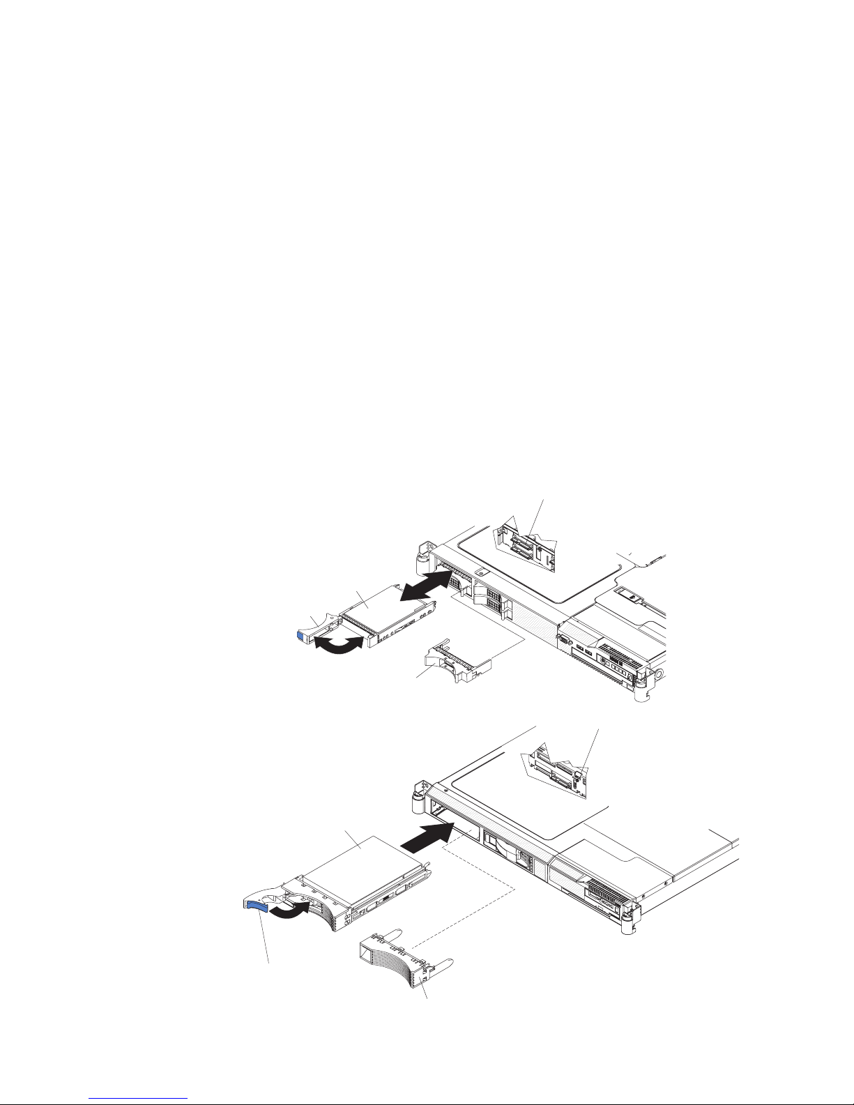
Installing a hot-swap hard disk drive
To install a 2.5-inch or 3.5-inch SAS hard disk drive, complete the following steps:
Note: If you have only one hard disk drive, you must install it in the upper-left bay.
Drive-tray assembly
Drive handle
Filler panel
Drive-tray assembly
SAS hard disk
drive backplane
SAS hard disk
drive backplane
Drive handle
(in open position)
Filler panel
Chapter 2. Installing options 31
Page 46

1. Read the safety information that begins on page v and “Installation guidelines”
on page 23.
2. Remove the filler panel from the empty drive bay.
3. Install the hard disk drive in the drive bay.
a. Make sure that the tray handle is open (that is, horizontal to the drive).
b. Align the drive assembly with the guide rails in the bay.
c. Gently push the drive assembly into the bay until the drive stops.
d. Push the tray handle to the closed (locked) position.
e. Check the hard disk drive status LED to verify that the hard disk drive is
operating correctly. If the amber hard disk drive status LED for a drive is lit
continuously, that drive is faulty and must be replaced. If the green hard disk
drive activity LED is flashing, the drive is being accessed.
If you have other options to install or remove, do so now. Otherwise, go to
“Completing the installation” on page 45.
Installing a simple-swap hard disk drive
To install a 3.5-inch SATA simple-swap hard disk drive, complete the following
steps:
Note: If you have only one hard disk drive, you must install it in the left bay.
Drive-tray assembly
Filler panel
SATA hard disk
drive back plate
1. Read the safety information that begins on page v and “Installation guidelines”
on page 23.
2. Turn off the server and disconnect the power cords and all external cables, if
necessary.
3. Remove the filler panel from the empty drive bay.
4. Insert the drive into the drive tray assembly.
a. Align the drive assembly with the guide rails in the bay.
b. Gently push the drive assembly into the bay until the rear of the drive snaps
into place with the connector on the back plate.
Install the filler panel in the drive bay.
5.
6. Reconnect the power cords and turn on the server.
7. Check the hard disk drive status LED to verify that the hard disk drive is
operating correctly. If the amber hard disk drive status LED for a drive is lit
32 IBM System x3550 Type 7978: User’s Guide
Page 47

continuously, that drive is faulty and must be replaced. If the green hard disk
drive activity LED is flashing, the drive is being accessed.
If you have other options to install or remove, do so now. Otherwise, go to
“Completing the installation” on page 45.
Replacing a riser-card assembly
The server comes with two PCI Express riser-card assemblies. You can replace a
PCI Express riser-card assembly with a PCI-X riser-card assembly.
To replace a PCI Express riser-card assembly with a PCI-X riser-card assembly,
complete the following steps:
1. Read the safety information that begins on page v and the “Installation
guidelines” on page 23.
2. Turn off the server and disconnect the power cords and all external cables, if
necessary; then, remove the server cover.
Expansion
slot cover
Adapter
support
bracket
Riser-card
assembly
Riser-card
connector
3. Remove the PCI Express riser-card assembly from slot 2 on the system board.
v If an adapter is installed in the riser-card assembly, disconnect any cables
that are connected to the adapter.
v Grasp the riser-card assembly at the rear edge and lift it from the riser-card
connector.
v Remove the adapter, if one is present, from the riser-card assembly.
v Store the riser-card assembly and the adapter in a safe place for possible
future use.
Install a PCI-X adapter in the PCI-X riser-card assembly. See “Installing an
4.
adapter” on page 34 for more information. Set any jumpers or switches on the
adapter as directed by the adapter manufacturer.
5. Insert the PCI-X riser-card assembly into the riser-card connector on the system
board. Make sure that it is fully seated.
you have other options to install or remove, do so now. Otherwise, go to
If
“Completing the installation” on page 45.
Chapter 2. Installing options 33
Page 48
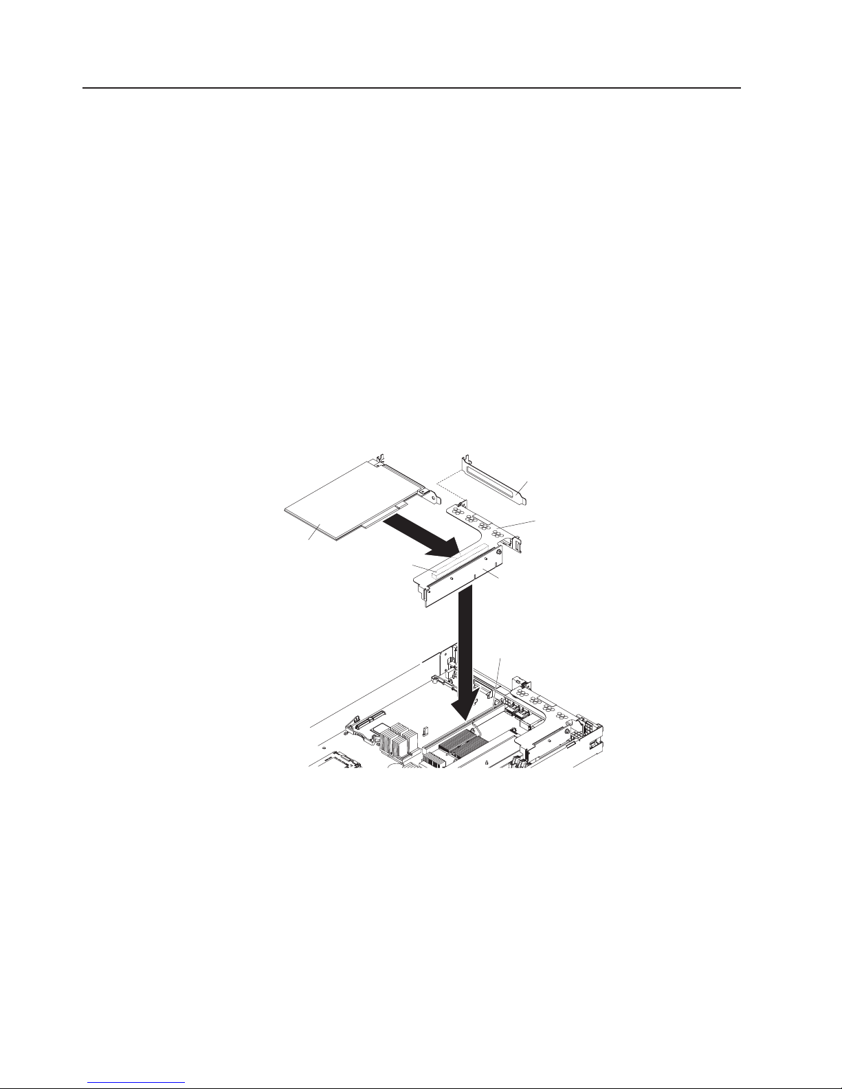
Installing an adapter
The following notes describe the types of adapters that the server supports and
other information that you must consider when installing an adapter:
v Locate the documentation that comes with the adapter and follow those
instructions in addition to the instructions in this section.
v There are two types of adapters that you can install, depending on which slots
are available. You can install the following types of adapters in PCI slots 1 and 2:
– Only a PCI Express adapter into slot 1
– Any PCI-X or PCI Express adapter into slot 2
PCI slot requires a riser card assembly. The server comes with two PCI
Each
Express riser card assemblies. If you plan to install a PCI-X adapter, you must
install the optional PCI-X riser card assembly.
To install an adapter, complete the following steps:
1. Read the safety information that begins on page v and the “Installation
guidelines” on page 23.
2. Turn off the server and peripheral devices and disconnect the power cords and
all external cables, if necessary; then, remove the server cover.
Expansion
slot cover
Adapter
PCI adapter
Expansion slot 2
support
bracket
Riser-card
assembly
Riser-card
connector
3. Follow the cabling instructions, if any come with the adapter. Route the adapter
cables before you install the adapter.
4. Insert the adapter into the riser-card assembly, aligning the edge connector on
the adapter with the connector on the riser-card assembly. Press the edge of
the connector firmly into the riser-card assembly. Make sure that the adapter
snaps into the riser-card assembly securely.
Attention: When you install an adapter, make sure that the adapter is
correctly seated in the riser-card assembly and that the riser-card assembly is
securely seated in the riser-card connector on the system board before you turn
on the server. An incorrectly seated adapter might cause damage to the system
board, the riser-card assembly, or the adapter.
5. Install the riser-card assembly in the server. See “Replacing a riser-card
assembly” on page 33 for more information.
34 IBM System x3550 Type 7978: User’s Guide
Page 49

6. Perform any configuration tasks that are required for the adapter.
you have other options to install or remove, do so now. Otherwise, go to
If
“Completing the installation” on page 45.
Replacing the RAID SAS controller
A ServeRAID SAS controller can be installed only in a dedicated slot on the system
board. The server comes with a ServeRAID-8k-l SAS controller installed. Yo u can
replace the ServeRAID-8k-l SAS controller with a ServeRAID-8k SAS controller.
This ServeRAID controller comes with a battery that you must connect to the
controller.
The following illustration shows the ServeRAID-8k-l SAS controller.
Retaining clips
ServeRAID
SAS controller
Connector
Retaining clips
To replace the ServeRAID-8k-l SAS controller with a ServeRAID-8k SAS controller,
complete the following steps:
1. Read the safety information that begins on page v and “Installation guidelines”
on page 23.
2. Turn off the server and peripheral devices and disconnect the power cords.
Remove the server cover.
3. Remove the ServeRAID-8k-l SAS controller from the connector.
a. Open the retaining clip on each end of the connector.
Attention: To avoid breaking the retaining clips or damaging the
connectors, handle the clips gently.
b. Carefully grasp the controller by its top edge or upper corners, and pull the
controller from the connector.
c. Place the ServeRAID-8k-l SAS controller into a static-protective package
and put it in a safe place.
Touch the static-protective package that contains the ServeRAID-8k controller to
4.
any unpainted surface on the outside of the server; then, grasp the adapter by
the top edge or upper corners of the controller and remove it from the package.
5. Position the ServeRAID-8k controller by aligning the edge connector with the
connector on the system board. Insert the controller firmly into the connector.
The retaining clips snap into the locked position when the controller is firmly
seated in the connector.
Chapter 2. Installing options 35
Page 50

Battery mounting tabs
Battery
Battery cable
Battery mounting
clips
Battery cable
connector
RAID controller
Attention: Incomplete insertion might cause damage to the server or the
controller.
6. Remove the battery from the RAID controller package.
7. Slide the battery mounting tabs into the battery mounting clips on the server
wall next to the connector.
8. Connect the RAID controller battery to the RAID controller.
When you restart the server, you will be prompted to import the existing
Note:
RAID configuration to the new ServeRAID controller.
If you have other options to install or remove, do so now. Otherwise, go to
“Completing the installation” on page 45.
Installing a memory module
The following notes describe the types of dual inline memory modules (DIMMs) that
the server supports and other information that you must consider when installing
DIMMs:
v The server supports up to eight Fully Buffered DIMM PC2-5300 512 MB, 1 GB, 2
GB, and 4 GB DIMMs, for a maximum of 32 GB of system memory. See
http://www.ibm.com/servers/eserver/serverproven/compat/us/ for a list of memory
modules that you can use with the server.
Note: Because some memory is reserved for system operation, the actual
usable memory size that is reported by the operating system is less than
the total installed size.
v The server comes with a minimum of two 512 MB DIMMs or two 1 GB DIMMs,
installed in slots 1 and 3 or slots 5 and 7. When you install additional DIMMs,
36 IBM System x3550 Type 7978: User’s Guide
Page 51

you must install two identical DIMMs at a time, in the order shown in the
following table, to maintain performance.
Table 2. DIMM installation sequence
Pair DIMM connectors
1 1 and 3
2 5 and 7
3 2 and 4
4 6 and 8
Figure 1. DIMM connectors, channels, and branches
Channel 2
Channel 3
DIMM 5 connector
DIMM 6 connector
DIMM 7 connector
DIMM 8 connector
Branch 1
DIMM 1 connector
DIMM 2 connector
DIMM 3 connector
DIMM 4 connector
Branch 0
Channel 1
Channel 0
v Each DIMM in a pair must be the same size, speed, type, and technology to
ensure that the server will operate correctly.
v You can configure the server to use memory mirroring. Memory mirroring stores
data in two pairs of DIMMs simultaneously. If a failure occurs, the memory
controller switches from the active pair to the mirroring pair. Memory mirroring
reduces the amount of available memory. Enable memory mirroring through the
Configuration/Setup Utility program.
When you use memory mirroring, you must install two pairs of DIMMs at a time.
The four DIMMs in each group must be identical. See the following table for the
installation sequence of DIMM connectors for memory mirroring.
Chapter 2. Installing options 37
Page 52

Table 3. Memory mirroring DIMM installation sequence
Group DIMM connectors
1 1, 3, 5, and 7
2 2, 4, 6, and 8
Table 4. Memory mirroring DIMM functions
Group Active DIMMs Mirroring DIMMs
1 1, 3 5, 7
2 2, 4 6, 8
v The server supports online-spare memory. This feature disables the failed
memory from the system configuration and activates an online-spare pair of
DIMMs to replace the failed active DIMM pair. Online-spare memory reduces the
amount of available memory. Before you can enable this feature, you must install
up to two additional pairs of DIMMs. The online-spare DIMM pairs must be the
same speed, type, and the same size as, or larger than, the largest active DIMM
pairs.
Enable online-spare memory through the Configuration/Setup Utility program.
The BIOS code assigns the online-spare DIMM pairs according to your DIMM
configuration. Two online-spare configurations are supported. See Table 5 for the
online-spare memory DIMM connector assignments.
Table 5. Online-spare DIMM connector assignments
Group DIMM connectors
1 1 and 3, 2 and 4
2 5 and 7, 6 and 8
v You can enable either online-spare memory or memory mirroring, but not both at
the same time. Online-spare memory provides more memory capacity than
mirroring; mirroring provides better memory protection but less memory capacity
than online-spare memory.
v When you install or remove DIMMs, the server configuration information
changes. When you restart the server, the system displays a message that
indicates that the memory configuration has changed.
install a DIMM, complete the following steps:
To
1. Read the safety information that begins on page v and “Installation guidelines”
on page 23.
2. Turn off the server and peripheral devices and disconnect the power cords and
all external cables, if necessary.
3. Remove the server cover.
Attention: To avoid breaking the retaining clips or damaging the DIMM
connectors, open and close the clips gently.
4. Open the retaining clip on each end of the DIMM connector.
38 IBM System x3550 Type 7978: User’s Guide
Page 53

5. Touch the static-protective package that contains the DIMM to any unpainted
metal surface on the outside of the server. Then, remove the DIMM from the
package.
6. Turn the DIMM so that the DIMM keys align correctly with the slot.
7. Insert the DIMM into the connector by aligning the edges of the DIMM with the
slots at the ends of the DIMM connector.
8. Firmly press the DIMM straight down into the connector by applying pressure on
both ends of the DIMM simultaneously. The retaining clips snap into the locked
position when the DIMM is firmly seated in the connector.
Note: If there is a gap between the DIMM and the retaining clips, the DIMM
has not been correctly inserted; open the retaining clips, remove the
DIMM, and then reinsert it.
If you have other options to install or remove, do so now. Otherwise, go to
“Completing the installation” on page 45.
Installing a microprocessor
The following notes describe the type of microprocessor that the server supports
and other information that you must consider when installing a microprocessor:
v The server supports up to two dual core microprocessors. The server comes with
one dual core microprocessor installed; you can install a second dual core
microprocessor.
v Read the documentation that comes with the microprocessor, so that you can
determine whether you have to update the BIOS code. To download the latest
level of BIOS code and other code updates for your server, go to
http://www.ibm.com/servers/eserver/support/xseries/index.html. Select System
x3550 from the Hardware list, and click the Download tab.
v When you install an additional microprocessor, you must also install one
additional cooling fan. See “Installing a fan” on page 43 for fan installation
information.
v To order an additional optional microprocessor, contact your IBM marketing
representative or authorized reseller.
v If you have to replace a microprocessor, call for service.
v The microprocessor speeds are automatically set for this server; therefore, you
do not have to set any microprocessor frequency-selection jumpers or switches.
v If the thermal-grease protective cover (for example, a plastic cap or tape liner) is
removed from the heat sink, do not touch the thermal grease on the bottom of
the heat sink or set down the heat sink. For details, see the information about
thermal grease in the Problem and Determination Service Guide.
Chapter 2. Installing options 39
Page 54

Note: Removing the heat sink from the microprocessor destroys the even
distribution of the thermal grease and requires replacing the thermal
grease.
Attention:
v A startup (boot) microprocessor must always be installed in microprocessor
socket 1 on the system board.
v To ensure correct server operation when you install an additional microprocessor,
use microprocessors that have the same cache size and type, and the same
clock speed. Microprocessor internal and external clock frequencies must be
identical.
v Do not remove the first microprocessor from the system board to install the
second microprocessor.
following illustrations show how to install the second microprocessor on the
The
system board. If you install a second microprocessor in the server, you must install
one additional fan.
Note: For simplicity, certain components are not shown in this illustration.
To install an additional microprocessor, complete the following steps:
1. Read the safety information that begins on page v and “Installation guidelines”
on page 23.
2. Turn off the server and peripheral devices and disconnect the power cords and
all external cables, if necessary (see “Turning off the server” on page 14).
Remove the server cover.
Attention: When you handle static-sensitive devices, take precautions to
avoid damage from static electricity. For details about handling these devices,
see “Handling static-sensitive devices” on page 25.
3. Locate microprocessor socket 2 on the system board.
4. Remove the microprocessor dust cover from the surface of the microprocessor
socket.
Microprocessor
bracket frame
Microprocessor
release lever
a. Press down and out on the release lever on the microprocessor socket. Lift
up the release lever until it stops in the fully open position (approximately
135° angle) and the top edge of the release lever has moved away from
the microprocessor socket.
b. Lift the hinged microprocessor bracket frame into an open position.
Remove the microprocessor dust cover from the bracket frame. Store the
dust cover in a safe place.
40 IBM System x3550 Type 7978: User’s Guide
Microprocessor
dust cover
Page 55

Attention: When you handle static-sensitive devices, take precautions to
avoid damage from static electricity. For details about handling these devices,
see “Handling static-sensitive devices” on page 25.
5. Touch the static-protective package that contains the new microprocessor to
any unpainted metal surface on the server; then, remove the microprocessor
from the package.
Attention: Use the vacuum tool that comes with the microprocessor to
install the microprocessor. Dropping the microprocessor during installation or
removal can damage the contacts. Also, contaminants on the microprocessor
contacts, such as oil from your skin, can cause connection failures between
the contacts and the socket.
6. Position the microprocessor over the microprocessor socket, using the vacuum
tool. Use the triangular alignment cutout on the microprocessor socket and the
triangular alignment mark on the microprocessor to assist you in aligning the
microprocessor to the socket. Then, carefully place the microprocessor into the
socket. Do not force the microprocessor, it only fits one way onto the socket.
Vacuum tool
Microprocessor
Alignment
Microprocessor
socket dust cover
7. Place the microprocessor bracket frame down over the microprocessor and the
marks
Microprocessor
release lever
microprocessor socket to secure the microprocessor position on the socket.
8. Rotate the microprocessor release lever into the closed position.
Attention: Do not touch the thermal grease on the bottom of the heat sink
after you remove the plastic cover. Touching the thermal grease will
contaminate it.
9. Remove the plastic cover from the heat sink. Install the heat sink on top of the
microprocessor with the thermal grease side down. Attach the heat sink to the
system board by alternating fastening the screws on the sides of the heat sink
with a Phillips screwdriver to apply even pressure to the microprocessor and to
avoid damage.
Chapter 2. Installing options 41
Page 56

Heat sink
Heat sink
installation
label
Microprocessor
Thermal grease
If you have to remove the heat sink after installing it, alternately loosen the
screws to help break the bond between the components without damaging
them.
10. If you removed any air baffles, reinstall them now. See page 26 for more
information.
If you have other options to install or remove, do so now. Otherwise, go to
“Completing the installation” on page 45.
42 IBM System x3550 Type 7978: User’s Guide
Page 57

Installing a fan
The server supports up to six hot-swap cooling fans. The server comes with five
fans that service the primary microprocessor and the DIMMs.
AIRFLOW
Fan 1
W
O
L
F
IR
A
Air baffle
Fan 3
AIRFLOW
Fan 2
AIRFLOW
AIRFLOW
Fan 4
Fan 5
Fan 6
AIRFLOW
AIRFLOW
If you install a second microprocessor in the server, you must install one additional
fan.
If you must replace a failed fan, see the instructions in the Problem Determination
and Service Guide.
Attention: To ensure proper operation, replace a failed fan as soon as possible.
To install an additional hot-swap fan, complete the following steps:
1. Read the safety information that begins on page v and “Installation guidelines”
on page 23.
2. Lift the two fan doors on the top of the server.
3. Orient the new fan over its position in the fan assembly bracket so that the
airflow indicator on the orange pull tab at the top of the fan points to the rear of
the server.
Chapter 2. Installing options 43
Page 58

Grommets
AIRFLOWAIRFLOW
Mounting slots
W
FLO
IR
A
Wiring channel
4. Place the fan down onto the fan assembly bracket until the four blue grommets
are correctly seated in the mounting slots.
5. Route the fan connection cable through the wiring channel.
6. Connect the fan cable by inserting the cable connector firmly into the orange fan
connector on the system board until it snaps into place.
Note: Make sure that the grommets and the fan cable are securely seated so
that the fan doors close correctly.
7. Close both fan doors and slide the server into the rack.
you have other options to install or remove, do so now. Otherwise, go to
If
“Completing the installation” on page 45.
Installing a Remote Supervisor Adapter II SlimLine
An optional Remote Supervisor Adapter II SlimLine can be installed only in a
dedicated connector on the system board. After the Remote Supervisor Adapter II
SlimLine is installed, the systems-management Ethernet port on the rear of the
server is active.
To install a Remote Supervisor Adapter II SlimLine, complete the following steps:
1. Read the safety information that begins on page v and “Installation guidelines”
on page 23.
2. Turn off the server and peripheral devices and disconnect the power cords and
all external cables, if necessary. Remove the server cover.
3. Remove the riser-card assembly in slot 2 and put it in a safe place. See
“Replacing a riser-card assembly” on page 33 for more information.
4. Put the protective plastic cover on the Remote Supervisor Adapter II SlimLine.
5. Turn the Remote Supervisor Adapter II SlimLine so that the keys on the
connector align correctly with the connector on the system board.
44 IBM System x3550 Type 7978: User’s Guide
Page 59

Remote Supervisor Adapter II SlimLine
Mounting bracket
Mounting bracket
retention latch
Mounting bracket
6. At a downward angle, slip the free end of the adapter under the tab on the
mounting bracket, aligning the holes in the adapter with the posts on the
mounting bracket and latch bracket. Rotate the rear of the adapter into the rear
mounting bracket, aligning the holes in the adapter with the posts on the
mounting bracket and latch bracket.
7. Press the Remote Supervisor Adapter II SlimLine firmly into the connector and
make sure that all tabs on both mounting brackets secure the adapter in place.
Attention: Incomplete insertion might cause damage to the server or the
adapter.
8. Replace the riser-card assembly in slot 2 on the system board. See “Replacing
a riser-card assembly” on page 33 for more information.
If you have other options to install or remove, do so now. Otherwise, go to
“Completing the installation.”
Completing the installation
To complete the installation, complete the following steps:
1. If you removed any air baffles, reinstall them now. See page 26 for baffle
location and more information.
2. If you removed the server cover, replace it and close the fan doors. For more
information, see “Replacing the server cover.”
3. Install the server in the rack cabinet. See the Rack Installation Instructions that
come with the server for instructions.
4. Connect the cables and power cords. For more information, see “Connecting
the cables” on page 46.
5. Update the server configuration. See “Updating the server configuration” on
page 47 for more information.
Replacing the server cover
To replace the server cover, complete the following steps:
v Slide the server cover toward the front of the server, fitting the cover into the tabs
for a secure fit.
v Close the covers over the fans and snap down the two fan cover-release latches.
v Tighten the thumbscrew at the back of the server.
Chapter 2. Installing options 45
Page 60

Connecting the cables
The following illustrations show the locations of the input and output connectors on
the front and rear of the server.
Thumbscrew
Fan door
USB 3 connector
USB 4 connector
Video connector
Figure 2. Front of server
3. Rear of server
Figure
Power supply
connector
Ethernet 1
Ethernet 2
USB 2
USB 1
Systems
management
Ethernet connector
Video
connector
Serial
connector
You must turn off the server before you connect or disconnect cables.
See the documentation that comes with any external devices for additional cabling
instructions. It might be easier for you to route cables before you connect the
devices to the server.
Cable identifiers are printed on the cables that come with the server and optional
devices. Use these identifiers to connect the cables to the correct connectors.
46 IBM System x3550 Type 7978: User’s Guide
Page 61

USB cable
release lever
USB cable
There are release levers on the Ethernet and systems management connectors. To
disconnect a cable from one of these connectors, pull up on the lever to release the
cable.
Ethernet activity LED
Ethernet port
Updating the server configuration
When you start the server for the first time after you add or remove an internal
option or external device, you might receive a message that the configuration has
changed. The Configuration/Setup Utility program starts automatically so that you
can save the new configuration settings.
Some options have device drivers that you must install. For information about
installing device drivers, see the documentation that comes with each option.
If the server has an optional RAID adapter and you have installed or removed a
hard disk drive, see the documentation that comes with the RAID adapter for
information about reconfiguring the disk arrays.
Ethernet speed LED
Ethernet cable
release lever
If you have installed a Remote Supervisor Adapter ll SlimLine to manage the server
remotely, see the Remote Supervisor Adapter ll SlimLine User’s Guide, which
comes with the adapter, for information about setting up, configuring, and using the
adapter.
For information about configuring the integrated Gigabit Ethernet controller, see
“Configuring the Gigabit Ethernet controller” on page 70.
Chapter 2. Installing options 47
Page 62

48 IBM System x3550 Type 7978: User’s Guide
Page 63

Chapter 3. Configuring the server
The following configuration programs come with the server:
v Configuration/Setup Utility program
The Configuration/Setup Utility program is part of the basic input/output system
(BIOS). Use it to change interrupt request (IRQ) settings, change the
startup-device sequence, set the date and time, and set passwords. For
information about using this program, see “Using the Configuration/Setup Utility
program.”
v Boot Menu program
The Boot Menu program is part of the BIOS. Use it to override the startup
sequence that is set in the Configuration/Setup Utility program and temporarily
assign a device to be first in the startup sequence.
v IBM ServerGuide Setup and Installation CD
The ServerGuide program provides software-setup tools and installation tools
that are designed for the server. Use this CD during the installation of the server
to configure basic hardware features, such as an integrated SAS controller with
RAID capabilities, and to simplify the installation of your operating system. For
information about using this CD, see “Using the ServerGuide Setup and
Installation CD” on page 56.
v Baseboard management controller utility programs
Use these programs to configure the baseboard management controller, to
update the firmware and sensor data record/field replaceable unit (SDR/FRU)
data, and to remotely manage a network. For information about using these
programs, see “Using the baseboard management controller” on page 58.
v Ethernet controller configuration
For information about configuring the Ethernet controller, see “Configuring the
Gigabit Ethernet controller” on page 70.
v RAID configuration programs:
– Use the IBM ServeRAID Configuration Utility program or ServeRAID Manager
to configure an array of hot-swap SAS or hot-swap SATA hard disk drives. For
information about using these programs, see “Configuring hot-swap SAS or
hot-swap S ATA RAID” on page 71.
®
– Use the Adaptec
simple-swap S ATA hard disk drives. For information about using these
programs, see “Configuring simple-swap SATA RAID” on page 73.
Remote Supervisor Adapter II SlimLine configuration
v
For information about setting up and cabling a Remote Supervisor Adapter II
SlimLine, see “Setting up an Remote Supervisor Adapter II SlimLine” on page 75.
HostRAID
™
configuration programs to configure an array of
Using the Configuration/Setup Utility program
Use the Configuration/Setup Utility program to:
v View configuration information
v View and change assignments for devices and I/O ports
v Set the date and time
v Set the startup characteristics of the server and the order of startup devices
v Set and change settings for advanced hardware features
v View, set, and change settings for power-management features
© Copyright IBM Corp. 2006 49
Page 64

v View and clear error logs
v Change interrupt request (IRQ) settings
v Resolve configuration conflicts
Starting the Configuration/Setup Utility program
Complete the following steps to start the Configuration/Setup Utility program:
1. Turn on the server.
2. When the prompt Press F1 for Configuration/Setup appears, press F1. If you
have set both a power-on password and an administrator password, you must
type the administrator password to access the full Configuration/Setup Utility
menu. If you do not type the administrator password, a limited
Configuration/Setup Utility menu is available.
3. Select settings to view or change.
Configuration/Setup Utility menu choices
The following choices are on the Configuration/Setup Utility main menu. Depending
on the version of the BIOS code, some menu choices might differ slightly from
these descriptions.
v System Summary
Select this choice to view configuration information, including the ID, speed, and
cache size of the microprocessors, a USB device summary, and the amount of
installed memory. When you make configuration changes through other options
in the Configuration/Setup Utility program, the changes are reflected in the
system summary; you cannot change settings directly in the system summary.
This choice is on the full and limited Configuration/Setup Utility menu.
v System Information
Select this choice to view information about the server. When you make changes
through other options in the Configuration/Setup Utility program, some of those
changes are reflected in the system information; you cannot change settings
directly in the system information. This choice is on the full Configuration/Setup
utility menu only.
– Product Data
Select this choice to view the machine type and model of the server, the serial
number, the system UUID, the system board identifier, the revision level or
issue date of the BIOS code and diagnostics code, and the version, date, and
build level of ROM code for the Remote Supervisor Adapter II SlimLine, if one
is installed.
– System card data
Select this choice to view the identity of the system board, power supplies,
DASD backplane, and power backplane.
This choice is on the full Configuration/Setup Utility menu only.
v Devices and I/O Ports
Select this choice to view or change assignments for devices and input/output
(I/O) ports. You can configure the serial ports, configure remote console
redirection, enable or disable integrated Ethernet controllers, the SAS controller,
IDE channels, and PCI slots, and view the system Ethernet MAC addresses. If
you disable a device, it cannot be configured, and the operating system will not
be able to detect it (this is equivalent to disconnecting the device).
This choice is on the full Configuration/Setup Utility menu only.
v Date and Time
50 IBM System x3550 Type 7978: User’s Guide
Page 65

Select this choice to set the date and time in the server, in 24-hour format
(hour:minute:second).
This choice is on the full Configuration/Setup Utility menu only.
v System Security
Select this choice to set passwords. See “Passwords” on page 54 for more
information.
This choice is on the full Configuration/Setup Utility menu only.
– Administrator Password
Select this choice to set or change an administrator password. An
administrator password is intended to be used by a system administrator; it
limits access to the full Configuration/Setup Utility menu. If an administrator
password is set, the full Configuration/Setup Utility menu is available only if
you type the administrator password at the password prompt. For more
information, see “Administrator password” on page 55.
– Power-on Password
Select this choice to set or change a power-on password. See “Power-on
password” on page 54 for more information.
Start Options
v
Select this choice to view or change the start options, including the startup
sequence, keyboard NumLock state, PXE boot option, and PCI device boot
priority. Changes in the startup options take effect when you start the server.
The startup sequence specifies the order in which the server checks devices to
find a boot record. The server starts from the first boot record that it finds. If the
server has Wake on LAN hardware and software and the operating system
supports Wake on LAN functions, you can specify a startup sequence for the
Wake on LAN functions. For example, you can define a startup sequence that
checks for a disc in the CD-RW/DVD drive, then checks the hard disk drive, and
then checks a network adapter.
This choice is on the full Configuration/Setup Utility menu only.
v Advanced Setup
Select this choice to change settings for advanced hardware features.
Important: The server might malfunction if these options are incorrectly
configured. Follow the instructions on the screen carefully.
This choice is on the full Configuration/Setup Utility menu only.
– System Partition VIsibility
Select this choice to make the System Partition hidden or visible.
– Memory Settings
Select this choice to enable or disable pairs of memory connectors, configure
the memory mode (flat, memory-mirroring, or online-spare), and view the
memory speed.
– CPU Options
Select this choice to specify the system cache type, and to enable or disable
hyper-threading, the pre-fetch queue, and Virtualization Technology for all
microprocessors in the server. Virtualization Technology enables the
microprocessor to appear to be a dedicated processor to each running
application in the system.
– PCI Bus Control
Select this choice to view the system resources that are used by installed PCI
(PCI-Express or PCI-X) devices. You can change the master latency timer
value, view and configure PCI interrupt routing, and enable or disable the
Chapter 3. Configuring the server 51
Page 66

loading and execution of ROM code per PCI slot (see message 1801 in the
Problem Determination and Service Guide on the IBM Documentation CD).
– PCI Slot/Device Information
This choice is available only if an optional Remote Supervisor Adapter II
SlimLine is installed. The Remote Supervisor Adapter II Slimline is considered
to be in PCI slot 0, which is the system board.
Select this choice to view the PCI device information, including PCI bus
number, for each PCI slot. Highlight a slot; then, press Enter to view the
details of the PCI devices that are connected to the slot. Follow the
instructions on the screen to page forward or backward through the devices
that are connected to the slot.
– RSA II Settings
This choice is available only if an optional Remote Supervisor Adapter II
SlimLine is installed.
Select this choice to configure the settings for the Remote Supervisor Adapter
II SlimLine.
- MAC Address
This is a nonselectable item that displays the MAC address of the Remote
Supervisor Adapter II SlimLine.
- DHCP IP Address
This is a nonselectable item that displays the current IP address of the
Remote Supervisor Adapter II SlimLine.
- DHCP Control
Specify whether to use the static IP address or use DHCP to dynamically
assign the IP address for the Remote Supervisor Adapter II SlimLine. If
DHCP times out while it is assigning an IP address, the system defaults to
the static IP address.
- Static IP Settings
Define the static IP address, subnet mask, and gateway address for the
Remote Supervisor Adapter II SlimLine.
- OS USB selection
Select the operating system to use to provide USB support for remote
access to the Remote Supervisor Adapter II SlimLine. The remote keyboard
and mouse access the Remote Supervisor Adapter II SlimLine through a
USB port. Linux OS is the default setting.
- Periodic SMI Generation
Enable or disable the periodic generation of a systems-management
interrupt. Disabled is the default setting.
Baseboard Management Controller (BMC) setting
–
Select this choice to change settings for the BMC.
- BMC Firmware Version
This is a nonselectable menu item that displays the BMC firmware version.
- BMC Build Level
This is a nonselectable menu item that displays the BMC firmware build
level.
- BMC Build Date
This is a nonselectable menu item that displays the BMC firmware build
date.
- BMC POST Watchdog
Enable or disable the BMC POST watchdog. Disable is the default setting.
52 IBM System x3550 Type 7978: User’s Guide
Page 67

- BMC POST Watchdog Timeout
Set the BMC POST watchdog timeout value. 5 minutes is the default
setting.
- System-BMC Serial Port Sharing
Enable or disable sharing the serial port between the BMC and the system.
Disabled is the default setting; it assigns the serial port to the BMC
exclusively.
- BMC Serial Port Access Mode
If serial-port sharing is enabled, specify the times and conditions during
which the BMC shares the serial port.
- Reboot System on NMI
Enable or disable restarting the system whenever a nonmaskable interrupt
(NMI) occurs. Disabled is the default.
- BMC Network Configuration
View the BMC MAC address and the current BMC IP address. Define the
static BMC IP address, subnet mask, and gateway address, and specify
whether to use the static IP address or have DHCP assign the BMC IP
address.
- BMC System Event Log
Select this choice to view the BMC system event log, which contains
messages about system events, such as devices that have been installed
or removed or a threshold that has been reached. Select Clear BMC SEL
to clear the BMC system event log.
- User Account Settings
Define user names and passwords for logging in to the BMC to remotely
control settings in the server, such as power settings.
Event/Error Logs
v
Select this choice to view and clear the POST error log and the system
event/error log.
– Post Error Log
Select this choice to view the three most recent error codes and messages
that were generated during POST. Select Clear POST Error Log to clear the
POST error log.
– System Event/Error Log
This choice is available only if an optional Remote Supervisor Adapter II
SlimLine is installed. Select this choice to view the error messages in the
system event/error log. Yo u can use the arrow keys to move between pages
in the error log. Select Clear System Event/Error Log to clear the system
event/error log.
The system event/error log contains all event and error messages that have
been generated during POST, by the system management interface handler,
and by the system service processor. Run the diagnostic programs to get
more information about error codes that occur. See the Problem
Determination and Service Guide on the IBM Documentation CD for
instructions for running the diagnostic programs.
Save Settings
v
Select this choice to save the changes that you have made in the settings.
v Restore Settings
Select this choice to cancel the changes that you have made in the settings and
restore the previous settings.
v Load Default Settings
Chapter 3. Configuring the server 53
Page 68

Passwords
Select this choice to cancel the changes that you have made in the settings and
restore the factory settings.
v Exit Setup
Select this choice to exit from the Configuration/Setup Utility program. If you have
not saved the changes that you have made in the settings, you are asked
whether you want to save the changes or exit without saving them.
From the System Security choice, you can set, change, and delete a power-on
password and an administrator password. The System Security choice is on the
full Configuration/Setup menu only.
If you set only a power-on password, you must type the power-on password to
complete the system startup and to have access to the full Configuration/Setup
Utility menu.
An administrator password is intended to be used by a system administrator; it
limits access to the full Configuration/Setup Utility menu. If you set only an
administrator password, you do not have to type a password to complete the
system startup, but you must type the administrator password to access the
Configuration/Setup Utility menu.
If you set a power-on password for a user and an administrator password for a
system administrator, you can type either password to complete the system startup.
A system administrator who types the administrator password has access to the full
Configuration/Setup Utility menu; the system administrator can give the user
authority to set, change, and delete the power-on password. A user who types the
power-on password has access to only the limited Configuration/Setup Utility menu;
the user can set, change, and delete the power-on password, if the system
administrator has given the user that authority.
Power-on password
If a power-on password is set, when you turn on the server, the system startup will
not be completed until you type the power-on password. You can use any
combination of up to seven characters (A–Z, a–z, and 0–9) for the password.
When a power-on password is set, you can enable the Unattended Start mode, in
which the keyboard and mouse remain locked but the operating system can start.
You can unlock the keyboard and mouse by typing the power-on password.
If you forget the power-on password, you can regain access to the server in any of
the following ways:
v If an administrator password is set, type the administrator password at the
password prompt. Start the Configuration/Setup Utility program and reset the
power-on password.
v Remove the battery from the server and then reinstall it. See the Problem
Determination and Service Guide on the IBM System x Documentation CD for
instructions for removing the battery.
v Change the position of the power-on password switch (enable switch 1 of the
system board switch block (SW2)) to bypass the power-on password check (see
the following illustration).
54 IBM System x3550 Type 7978: User’s Guide
Page 69

1
2
3
Boot block recovery
jumper (J14)
8 7 6 5 4 3 2 1
ON
System board switch
block (SW2)
Attention: Before changing any switch settings or moving any jumpers, turn off
the server; then, disconnect all power cords and external cables. See the safety
information that begins on page v. Do not change settings or move jumpers on
any system-board switch or jumper blocks that are not shown in this document.
While the server is turned off, move switch 1 of the switch block (SW2) to the On
position to enable the power-on password override. You can then start the
Configuration/Setup Utility program and reset the power-on password. Yo u do not
have to return the switch to the previous position.
The power-on password override jumper does not affect the administrator
password.
Administrator password
If an administrator password is set, you must type the administrator password for
access to the full Configuration/Setup Utility menu. You can use any combination of
up to seven characters (A–Z, a–z, and 0–9) for the password.
Attention: If you set an administrator password and then forget it, there is no way
to change, override, or remove it. You must replace the system board.
Using the Boot Menu program
The Boot Menu program is a built-in, menu-driven configuration utility program that
you can use to temporarily redefine the first startup device without changing
settings in the Configuration/Setup utility program.
To use the Boot Menu program, complete the following steps:
1. Turn off the server.
2. Restart the server.
Chapter 3. Configuring the server 55
Page 70

3. Press F12. If a bootable USB mass storage device is installed, a submenu item
(USB Key/Disk) is displayed.
4. Select an item from the (Select Boot Device) menu.
5. Select an option, and then Exit and continue booting.
next time the server starts, it returns to the startup sequence that is set in the
The
Configuration/Setup Utility program.
Starting the backup BIOS
The system board contains a backup copy area for the BIOS code. This is a
secondary copy of BIOS code that you update only during the process of updating
BIOS code. If the primary copy of the BIOS code becomes damaged, use this
backup copy.
To force the server to start from the backup copy, turn off the server; then, place the
J14 jumper in the backup position (pins 2 and 3).
Use the backup copy of the BIOS code until the primary copy is restored. After the
primary copy is restored, turn off the server; then, move the J14 jumper back to the
primary position.
Using the ServerGuide Setup and Installation CD
The ServerGuide Setup and Installation CD contains a setup and installation
program that is designed for your server. The ServerGuide program detects the
server model and hardware options that are installed and uses that information
during setup to configure the hardware. The ServerGuide program simplifies
operating-system installations by providing updated device drivers and, in some
cases, installing them automatically.
If a later version of the ServerGuide program is available, you can download a free
image of the ServerGuide Setup and Installation CD. To download the image, go to
the IBM ServerGuide Web page at http://www.ibm.com/pc/qtechinfo/MIGR4ZKPPT.html.
The ServerGuide program has the following features:
v An easy-to-use interface
v Diskette-free setup, and configuration programs that are based on detected
hardware
v ServeRAID Manager program, which configures your ServeRAID adapter
v Device drivers that are provided for your server model and detected hardware
v Operating-system partition size and file-system type that are selectable during
setup
ServerGuide features
Features and functions can vary slightly with different versions of the ServerGuide
program. To learn more about the version that you have, start the ServerGuide
Setup and Installation CD and view the online overview. Not all features are
supported on all server models.
The ServerGuide program requires a supported IBM server with an enabled
startable (bootable) CD drive. In addition to the ServerGuide Setup and Installation
CD, you must have your operating-system CD to install the operating system.
56 IBM System x3550 Type 7978: User’s Guide
Page 71

The ServerGuide program performs the following tasks:
v Sets system date and time
v Detects the RAID adapter or controller and runs the SAS RAID configuration
program
v Checks the microcode (firmware) levels of a ServeRAID adapter and determines
whether a later level is available from the CD
v Detects installed hardware options and provides updated device drivers for most
adapters and devices
v Provides diskette-free installation for supported Windows operating systems
v Includes an online readme file with links to tips for your hardware and
operating-system installation
Setup and configuration overview
When you use the ServerGuide Setup and Installation CD, you do not need setup
diskettes. Yo u can use the CD to configure any supported IBM server model. The
setup program provides a list of tasks that are required to set up your server model.
On a server with a ServeRAID adapter or SAS/SATA controller with RAID
capabilities, you can run the SAS RAID configuration program to create logical
drives.
Note: Features and functions can vary slightly with different versions of the
ServerGuide program.
When you start the ServerGuide Setup and Installation CD, the program prompts
you to complete the following tasks:
v Select your language.
v Select your keyboard layout and country.
v View the overview to learn about ServerGuide features.
v View the readme file to review installation tips for your operating system and
adapter.
v Start the operating-system installation. Yo u will need your operating-system CD.
Typical operating-system installation
The ServerGuide program can reduce the time it takes to install an operating
system. It provides the device drivers that are required for your hardware and for
the operating system that you are installing. This section describes a typical
ServerGuide operating-system installation.
Note: Features and functions can vary slightly with different versions of the
ServerGuide program.
1. After you have completed the setup process, the operating-system installation
program starts. (You will need your operating-system CD to complete the
installation.)
2. The ServerGuide program stores information about the server model, service
processor, hard disk drive controllers, and network adapters. Then, the program
checks the CD for newer device drivers. This information is stored and then
passed to the operating-system installation program.
3. The ServerGuide program presents operating-system partition options that are
based on your operating-system selection and the installed hard disk drives.
4. The ServerGuide program prompts you to insert your operating-system CD and
restart the server. At this point, the installation program for the operating system
takes control to complete the installation.
Chapter 3. Configuring the server 57
Page 72

Installing your operating system without ServerGuide
If you have already configured the server hardware and you decide not to use the
ServerGuide program to install your operating system, complete the following steps
to download the latest operating-system installation instructions from the IBM Web
site.
Note: Changes are made periodically to the IBM Web site. The actual procedure
might vary slightly from what is described in this document.
1. Go to http://www.ibm.com/support/.
2. Under Search technical support, type System x3550, and click Search.
3. Select the installation instructions for your operating system.
Using the baseboard management controller
The baseboard management controller provides basic service-processor
environmental monitoring functions. If an environmental condition exceeds a
threshold or if a system component fails, the baseboard management controller
lights LEDs to help you diagnose the problem and also records the error in the
system event/error log.
The baseboard management controller also provides the following remote server
management capabilities through the OSA SMBridge management utility program:
v Command-line interface (IPMI Shell)
The command-line interface provides direct access to server management
functions through the IPMI 2.0 protocol. Use the command-line interface to issue
commands to control the server power, view system information, and identify the
server. Yo u can also save one or more commands as a text file and run the file
as a script.
v Serial over LAN
Establish a Serial over LAN (SOL) connection to manage servers from a remote
location. Yo u can remotely view and change the BIOS settings, restart the server,
identify the server, and perform other management functions. Any standard Telnet
client application can access the SOL connection.
Enabling and configuring SOL using the OSA SMBridge management
utility program
To enable and configure the server for SOL by using the OSA SMBridge
management utility program, you must update and configure the BIOS code; update
and configure the baseboard management controller (BMC) firmware; update and
configure the Ethernet controller firmware; and enable the operating system for an
SOL connection.
Note: In an SOL session, use the following commands instead of function keys:
v To start the Configuration/Setup Utility program when the prompt Press F1
for Configuration/Setup.
v To start the diagnostic programs, press F2 for Diagnostics when the
prompt appears.
v To recover BIOS, press F3 for BIOS Recovery when the prompt appears.
BIOS update and configuration
To update and configure the BIOS code to enable SOL, complete the following
steps:
58 IBM System x3550 Type 7978: User’s Guide
Page 73

1. Update the BIOS code:
a. Download the latest version of the BIOS code from http://www.ibm.com/pc/
support/.
b. Update the BIOS code, following the instructions that come with the update
file that you downloaded.
Configure the BIOS settings:
2.
a. When prompted to start the Configuration/Setup Utility program, restart the
server and press F1.
b. Select Devices and I/O Ports; then, make sure that the values are set as
follows:
v Serial Port A: Auto-configure
v Serial Port B: Auto-configure
Select Remote Console Redirection; then, make sure that the values are
c.
set as follows:
v Remote Console Active: Enabled
v Remote Console COM Port: COM 1
v Remote Console Baud Rate: 19200
v Remote Console Data Bits: 8
v Remote Console Parity: None
v Remote Console Stop Bits: 1
v Remote Console Text Emulation: ANSI
v Remote Console Keyboard Emulation: ANSI
v Remote Console Active After Boot: Enabled
v Remote Console Flow Control: Hardware
Press Esc twice to exit the Remote Console Redirection and Devices and
d.
I/O Ports sections of the Configuration/Setup Utility program.
Note: Do not use Planar Ethernet 1 for PXE/DHCP booting or installation.
e. Select Start Options; then, set Planar Ethernet PXE/DHCP to one of the
following settings:
v Disabled
v Planar Ethernet 2. If you set Planar Ethernet PXE/DHCP to Planar
Ethernet 2, you must also set Run PXE only on selected Planar NIC to
Enabled.
f. Press Esc to exit the Start Options section of the Configuration/Setup Utility
program.
g. Select Save Settings; then, press Enter.
h. Press Enter to confirm.
i. Select Exit Setup; then, press Enter.
j. Make sure that Yes, exit the Setup Utility is selected; then, press Enter.
Linux configuration
®
For SOL operation on the server, you must configure the Linux
to expose the Linux initialization (booting) process. This enables users to log in to
the Linux console through an SOL session and directs Linux output to the serial
console. See the documentation for your specific Linux operating-system type for
information and instructions.
operating system
Chapter 3. Configuring the server 59
Page 74

Use one of the following procedures to enable SOL sessions for your Linux
operating system. You must be logged in as a root user to perform these
procedures.
Red Hat Enterprise Linux ES 2.1 configuration:
Note: This procedure is based on a default installation of Red Hat Enterprise Linux
ES 2.1. The file names, structures, and commands might be different for
other versions of Red Hat Linux.
Complete the following steps to configure the general Linux parameters for SOL
operation when you are using the Red Hat Enterprise Linux ES 2.1 operating
system.
Note: Hardware flow control prevents character loss during communication over a
serial connection. You must enable it when you are using a Linux operating
system.
1. Add the following line to the end of the # Run gettys in standard runlevels
section of the /etc/inittab file. This enables hardware flow control and enables
users to log in through the SOL console.
7:2345:respawn:/sbin/agetty -h ttyS0 19200 vt102
2. Add the following line at the bottom of the /etc/securetty file to enable a user to
log in as the root user through the SOL console:
ttyS0
LILO configuration: If you are using LILO, complete the following steps:
1. To modify the /etc/lilo.conf file, complete the following steps:
a. Add the following text to the end of the first default=linux line
-Monitor
b. Comment out the map=/boot/map line by adding a # at the beginning of this
line.
c. Comment out the message=/boot/message line by adding a # at the beginning
of this line.
d. Add the following line before the first image= line:
# This will allow you to only Monitor the OS boot via SOL
e. Add the following text to the end of the first label=linux line:
-Monitor
f. Add the following line to the first image= section. This enables SOL.
append="console=ttyS0,19200n8 console=tty1"
g. Add the following lines between the two image= sections:
# This will allow you to Interact with the OS boot via SOL
image=/boot/vmlinuz-2.4.9-e.12smp
label=linux-Interact
initrd=/boot/initrd-2.4.9-e.12smp.img
read-only
root=/dev/hda6
append="console=tty1 console=ttyS0,19200n8 "
The following examples show the original content of the /etc/lilo.conf file and the
content of this file after modification.
60 IBM System x3550 Type 7978: User’s Guide
Page 75

Original /etc/lilo.conf contents
prompt
timeout=50
default=linux
boot=/dev/hda
map=/boot/map
install=/boot/boot.b
message=/boot/message
linear
image=/boot/vmlinuz-2.4.9-e.12smp
label=linux
initrd=/boot/initrd-2.4.9-e.12smp.img
read-only
root=/dev/hda6
image=/boot/vmlinuz-2.4.9-e.12
label=linux-up
initrd=/boot/initrd-2.4.9-e.12.img
read-only
root=/dev/hda6
Chapter 3. Configuring the server 61
Page 76

Modified /etc/lilo.conf contents
prompt
timeout=50
default=linux-Monitor
boot=/dev/hda
#map=/boot/map
install=/boot/boot.b
#message=/boot/message
linear
# This will allow you to only Monitor the OS boot via SOL
image=/boot/vmlinuz-2.4.9-e.12smp
label=linux-Monitor
initrd=/boot/initrd-2.4.9-e.12smp.img
read-only
root=/dev/hda6
append="console=ttyS0,19200n8 console=tty1"
# This will allow you to Interact with the OS boot via SOL
image=/boot/vmlinuz-2.4.9-e.12smp
label=linux-Interact
initrd=/boot/initrd-2.4.9-e.12smp.img
read-only
root=/dev/hda6
append="console=tty1 console=ttyS0,19200n8 "
image=/boot/vmlinuz-2.4.9-e.12
label=linux-up
initrd=/boot/initrd-2.4.9-e.12.img
read-only
root=/dev/hda6
2. Run the lilo command to store and activate the LILO configuration.
When the Linux operating system starts, a LILO boot: prompt is displayed instead
of the graphical user interface. Press Ta b at this prompt to install all of the boot
options that are listed. To load the operating system in interactive mode, type
linux-Interact and then press Enter.
GRUB configuration: If you are using GRUB, complete the following steps to
modify the /boot/grub/grub.conf file:
1. Comment out the splashimage= line by adding a # at the beginning of this line.
2. Add the following line before the first title= line:
# This will allow you to only Monitor the OS boot via SOL
3. Append the following text to the first title= line:
SOL Monitor
4. Append the following text to the kernel/ line of the first title= section:
console=ttyS0,19200 console=tty1
5. Add the following five lines between the two title= sections:
# This will allow you to Interact with the OS boot via SOL
title Red Hat Linux (2.4.9-e.12smp) SOL Interactive
root (hd0,0)
62 IBM System x3550 Type 7978: User’s Guide
Page 77

kernel /vmlinuz-2.4.9-e.12smp ro root=/dev/hda6 console=tty1
console=ttyS0,19200
initrd /initrd-2.4.9-e.12smp.img
Note: The entry that begins with kernel /vmlinuz is shown with a line break after
console=tty1. In your file, the entire entry must all be on one line.
The following examples show the original content of the /boot/grub/grub.conf file
and the content of this file after modification.
Original /boot/grub/grub.conf contents
#grub.conf generated by anaconda
#
# Note that you do not have to rerun grub after making changes to this file
# NOTICE: You have a /boot partition. This means that
# all kernel and initrd paths are relative to /boot/, eg.
# root (hd0,0)
# kernel /vmlinuz-version ro root=/dev/hda6
# initrd /initrd-version.img
#boot=/dev/hda
default=0
timeout=10
splashimage=(hd0,0)/grub/splash.xpm.gz
title Red Hat Enterprise Linux ES (2.4.9-e.12smp)
root (hd0,0)
kernel /vmlinuz-2.4.9-e.12smp ro root=/dev/hda6
initrd /initrd-2.4.9-e.12smp.img
title Red Hat Enterprise Linux ES-up (2.4.9-e.12)
root (hd0,0)
kernel /vmlinuz-2.4.9-e.12 ro root=/dev/hda6
initrd /initrd-2.4.9-e.12.img
Chapter 3. Configuring the server 63
Page 78

Modified /boot/grub/grub.conf contents
#grub.conf generated by anaconda
#
# Note that you do not have to rerun grub after making changes to this file
# NOTICE: You have a /boot partition. This means that
# all kernel and initrd paths are relative to /boot/, eg.
# root (hd0,0)
# kernel /vmlinuz-version ro root=/dev/hda6
# initrd /initrd-version.img
#boot=/dev/hda
default=0
timeout=10
# splashimage=(hd0,0)/grub/splash.xpm.gz
# This will allow you to only Monitor the OS boot via SOL
title Red Hat Enterprise Linux ES (2.4.9-e.12smp) SOL Monitor
root (hd0,0)
kernel /vmlinuz-2.4.9-e.12smp ro root=/dev/hda6 console=ttyS0,19200 console=tty1
initrd /initrd-2.4.9-e.12smp.img
# This will allow you to Interact with the OS boot via SOL
title Red Hat Linux (2.4.9-e.12smp) SOL Interactive
root (hd0,0)
kernel /vmlinuz-2.4.9-e.12smp ro root=/dev/hda6 console=tty1 console=ttyS0,19200
initrd /initrd-2.4.9-e.12smp.img
title Red Hat Enterprise Linux ES-up (2.4.9-e.12)
root (hd0,0)
kernel /vmlinuz-2.4.9-e.12 ro root=/dev/hda6
initrd /initrd-2.4.9-e.12.img
You must restart the Linux operating system after you complete these procedures
for the changes to take effect and to enable SOL.
SUSE SLES 8.0 configuration:
Note: This procedure is based on a default installation of SUSE Linux Enterprise
Server (SLES) 8.0. The file names, structures, and commands might be
different for other versions of SUSE LINUX.
Complete the following steps to configure the general Linux parameters for SOL
operation when using the SLES 8.0 operating system.
Note: Hardware flow control prevents character loss during communication over a
serial connection. You must enable it when using a Linux operating system.
1. Add the following line to the end of the # getty-programs for the normal
runlevels section of the /etc/inittab file. This enables hardware flow control and
enables users to log in through the SOL console.
7:2345:respawn:/sbin/agetty -h ttyS0 19200 vt102
2. Add the following line after the tty6 line at the bottom of the /etc/securetty file to
enable a user to log in as the root user through the SOL console:
ttyS0
3. Complete the following steps to modify the /boot/grub/menu.lst file:
64 IBM System x3550 Type 7978: User’s Guide
Page 79

a. Comment out the gfxmenu line by adding a # in front of the word gfxmenu.
b. Add the following line before the first title line:
# This will allow you to only Monitor the OS boot via SOL
c. Append the following text to the first title line:
SOL Monitor
d. Append the following text to the kernel line of the first title section:
console=ttyS0,19200 console=tty1
e. Add the following four lines between the first two title sections:
# This will allow you to Interact with the OS boot via SOL
title linux SOL Interactive
kernel (hd0,1)/boot/vmlinuz root=/dev/hda2 acpi=oldboot vga=791
console=tty1 console=ttyS0,19200
initrd (hd0,1)/boot/initrd
The following examples show the original content of the /boot/grub/menu.lst
file and the content of this file after modification.
Original /boot/grub/menu.lst contents Notes
gfxmanu (hd0,1)/boot/message
color white/blue black/light-gray
default 0
timeout 8
title linux
kernel (hd0,1)/boot/vmlinuz root=/dev/hda2 acpi=oldboot vga=791 1
initrd (hd0,1)/boot/initrd
title floppy
root
chainloader +1
title failsafe
kernal (hd0,1)/boot/vmlinuz.shipped root=/dev/hda2 ide=nodma apm=off vga=normal nosmp 1
disableapic maxcpus=0 3
initrd (hd0,1)/boot/initrd.shipped
Note 1: The kernel line is shown with a line break. In your file, the entire entry must all be on one line.
Modified /boot/grub/menu.lst contents Notes
#gfxmanu (hd0,1)/boot/message
color white/blue black/light-gray
default 0
timeout 8
# This will allow you to only Monitor the OS boot via SOL
title linux SOL Monitor
kernel (hd0,1)/boot/vmlinuz root=/dev/hda2 acpi=oldboot vga=791 console=ttyS0,19200 1
console=tty1
initrd (hd0,1)/boot/initrd
# This will allow you to Interact with the OS boot via SOL
title linux SOL Interactive
kernel (hd0,1)/boot/vmlinuz root=/dev/hda2 acpi=oldboot vga=791 console=tty1 console=ttyS0,19200
initrd (hd0,1)/boot/initrd
title floppy
Chapter 3. Configuring the server 65
Page 80

Modified /boot/grub/menu.lst contents Notes
root
chainloader +1
title failsafe
kernel (hd0,1)/boot/vmlinuz.shipped root=/dev/hda2 ide=nodma apm=off vga=normal nosmp 1
disableapic maxcpus=0 3
initrd (hd0,1)/boot/initrd.shipped
Note 1: The kernel line is shown with a line break. In your file, the entire entry must all be on one line.
You must restart the Linux operating system after you complete these procedures
for the changes to take effect and to enable SOL.
Microsoft Windows 2003 Standard Edition configuration
Note: This procedure is based on a default installation of the Microsoft Windows
2003 operating system.
Complete the following steps to configure the Windows 2003 operating system for
SOL operation. Yo u must be logged in as a user with administrator access to
perform this procedure.
1. Complete the following steps to determine which boot entry ID to modify:
a. Type bootcfg at a Windows command prompt; then, press Enter to display
the current boot options for your server.
b. In the Boot Entries section, locate the boot entry ID for the section with an
OS friendly name of Windows Server 2003, Standard. Write down the boot
entry ID for use in the next step.
To enable the Microsoft Windows Emergency Management System (EMS), at a
2.
Windows command prompt, type
bootcfg /EMS ON /PORT COM1 /BAUD 19200 /ID boot_id
where boot_id is the boot entry ID from step 1b; then, press Enter.
3. Complete the following steps to verify that the EMS console is redirected to the
COM1 serial port:
a. Type bootcfg at a Windows command prompt; then, press Enter to display
the current boot options for your server.
b. Verify the following changes to the bootcfg settings:
v In the Boot Loader Settings section, make sure that redirect is set to
COM1 and that redirectbaudrate is set to 19200.
v In the Boot Entries section, make sure that the OS Load Options: line
has /redirect appended to the end of it.
The following examples show the original bootcfg program output and the output
after modification.
66 IBM System x3550 Type 7978: User’s Guide
Page 81

Original bootcfg program output
Boot Loader Settings
----------------------------
timeout: 30
default: multi(0)disk(0)rdisk(0)partition(1)\WINDOWS
Boot Entries
----------------
Boot entry ID: 1
OS Friendly Name: Windows Server 2003, Standard
Path: multi(0)disk(0)rdisk(0)partition(1)\WINDOWS
OS Load Options: /fastdetect
Modified bootcfg program output
Boot Loader Settings
----------------------------
timeout: 30
default: multi(0)disk(0)rdisk(0)partition(1)\WINDOWS
redirect: COM1
redirectbaudrate: 19200
Boot Entries
----------------
Boot entry ID: 1
OS Friendly Name: Windows Server 2003, Standard
Path: multi(0)disk(0)rdisk(0)partition(1)\WINDOWS
OS Load Options: /fastdetect /redirect
You must restart the Windows 2003 operating system after you complete this
procedure for the changes to take effect and to enable SOL.
Installing the OSA SMBridge management utility program
Complete the following steps to install the OSA SMBridge management utility
program on a server running a Windows operating system:
1. Go to http://www.ibm.com/pc/support/ and download the utility program and
create the OSA BMC Management Utility CD.
2. Insert the OSA BMC Management Utility CD into the drive. The InstallShield
wizard starts, and a window similar to that shown in the following illustration
opens.
Chapter 3. Configuring the server 67
Page 82

3. Follow the prompts to complete the installation.
The installation program prompts you for a TCP/IP port number and an IP
address. Specify an IP address, if you want to limit the connection requests that
will be accepted by the utility program. To accept connections from any server,
type INADDR_ANY as the IP address. Also specify the port number that the utility
program will use. These values will be recorded in the smbridge.cfg file for the
automatic startup of the utility program.
Complete
the following steps to install the OSA SMBridge management utility
program on a server running a Linux operating system. You must be logged in as a
root user to perform these procedures.
1. Go to http://www.ibm.com/pc/support/. Download the utility program and create
the OSA BMC Management Utility CD.
2. Insert the OSA BMC Management Utility CD into the drive.
3. Type mount/mnt/cdrom.
4. Locate the directory where the installation RPM package is located and type
cd/mnt/cdrom.
5. Type the following command to run the RPM package and start the installation:
rpm -ivh osasmbridge-2.0-xx.i386.rpm
6. Follow the prompts to complete the installation. When the installation is
complete, the utility copies files to the following directories:
/etc/init.d/SMBridge
/etc/smbridge.cfg
/usr/sbin/smbridged
/var/log/smbridge
/var/log/smbridge/LICENSE
utility starts automatically when the server is started. You can also locate the
The
/ect/init.d directory to start the utility and use the following commands to manage
the utility:
68 IBM System x3550 Type 7978: User’s Guide
Page 83

smbridge status
smbridge start
smbridge stop
smbridge restart
Using the baseboard management controller utility programs
Use the baseboard management controller utility programs to configure the
baseboard management controller, download firmware updates and remotely
manage a network.
Using the baseboard management controller configuration utility
program
Use the baseboard management controller configuration utility program to view or
change the baseboard management controller configuration settings. You can also
use the utility program to save the configuration to a file for use on multiple servers.
To download the program, go to http://www.ibm.com/pc/support/; then, copy the
bmc_cfg.exe file to a configuration utility diskette.
To start the baseboard management controller configuration utility program,
complete the following steps:
1. Insert the configuration utility diskette into the diskette drive and restart the
server.
2. From a command-line prompt, type bmc_cfg and press Enter.
3. Follow the instructions on the screen.
Using the baseboard management controller firmware update
utility program
Use the baseboard management controller firmware update utility program to
download a baseboard management controller firmware update. The firmware
update utility program updates the baseboard management controller firmware only
and does not affect any device drivers.
Note: To ensure proper server operation, be sure to update the server baseboard
management controller firmware before you update the BIOS code.
To update the firmware, if the Linux or Windows operating-system update package
is available from the World Wide Web and you have obtained the applicable update
package, follow the instructions that come with the update package.
Using the OSA SMBridge management utility program
Use the OSA SMBridge management utility program to remotely manage and
configure a network. The utility program provides the following remote management
capabilities:
v CLI (command-line interface) mode
Use CLI mode to remotely perform power-management and system identification
control functions over a LAN or serial port interface from a command-line
interface. Use CLI mode also to remotely view the system event/error log.
Use the following commands in CLI mode:
– identify
Control the system-locator LED on the front of the server.
– power
Turn the server on and off remotely.
Chapter 3. Configuring the server 69
Page 84

– sel
Perform operations with the system event/error log.
– sysinfo
Display general system information that is related to the server and the
baseboard management controller.
Serial over LAN
v
Use the Serial over LAN capability to remotely perform control and management
functions over a Serial over LAN (SOL) network. Yo u can also use SOL to
remotely view and change the server BIOS settings.
At a command prompt, type telenet localhost 623 to access the SOL network.
Type help at the smbridge> prompt for more information.
Use the following commands in an SOL session:
– connect
Connect to the LAN. Type connect -ip ip_address -u username -p
password.
– identify
Control the system-locator LED on the front of the server.
– power
Turn the server on and off remotely.
– reboot
Force the server to restart.
– sel get
Display the system event/error log.
– sol
Configure the SOL function.
– sysinfo
Display system information that is related to the server and the globally
unique identifier (GUID).
Configuring the Gigabit Ethernet controller
The Ethernet controllers are integrated on the system board. They provide an
interface for connecting to a 10-Mbps, 100-Mbps, or 1-Gbps network and provide
full-duplex (FDX) capability, which enables simultaneous transmission and reception
of data on the network. If the Ethernet ports in the server support auto-negotiation,
the controllers detect the data-transfer rate (10BASE-T, 100BASE-TX, or
1000BASE-T) and duplex mode (full-duplex or half-duplex) of the network and
automatically operate at that rate and mode.
You do not have to set any jumpers or configure the controllers. However, you must
install a device driver to enable the operating system to address the controllers. For
device drivers and information about configuring the Ethernet controllers, see the
Broadcom NetXtreme II Gigabit Ethernet Software CD that comes with the server.
To find updated information about configuring the controllers, complete the following
steps.
Note: Changes are made periodically to the IBM Web site. The actual procedure
might vary slightly from what is described in this document.
1. Go to http://www.ibm.com/support/.
2. Under Search technical support, type System x3550, and click Search.
70 IBM System x3550 Type 7978: User’s Guide
Page 85

3. In the Additional search terms field, type ethernet, and click Go.
Configuring hot-swap SAS or hot-swap SATA RAID
Use the IBM ServeRAID Configuration Utility program or ServeRAID Manager to
configure and manage hot-swap SAS or hot-swap SATA redundant array of
independent disks (RAID). Be sure to use these programs as described in this
document.
v Use the IBM ServeRAID Configuration Utility program to:
– Perform a low-level format on a hard disk drive
– View or change IDs for some attached devices
– Set protocol parameters on hard disk drives
v Use ServeRAID Manager to:
– Configure arrays
– View the RAID configuration and associated devices
– Monitor operation of the RAID controller
Consider the following information when using the IBM ServeRAID Configuration
Utility program or ServeRAID Manager to configure and manage arrays:
v The ServeRAID-8k-l SAS controller that comes with the server supports only
RAID level-0 and RAID level-1. Servers that come with four 2.5-inch hot-swap
SAS drives also support RAID level-10. You can replace the ServeRAID-8k-l SAS
controller with a ServeRAID-8k SAS controller that supports additional RAID
levels.
v Hard disk drive capacities affect how you create arrays. The drives in an array
can have different capacities, but the ServeRAID controller treats them as if they
all have the capacity of the smallest hard disk drive.
v To help ensure signal quality, do not mix drives with different speeds and data
rates.
v Do not include SAS and SATA drives in the same array.
v To update the firmware and BIOS code for an optional ServeRAID controller, you
must use the IBM ServeRAID Support CD that comes with the ServeRAID
option.
Using the IBM ServeRAID Configuration Utility program
Use the IBM ServeRAID Configuration Utility program to perform the following
tasks:
v Configure a redundant array of independent disks (RAID) array
v View or change the RAID configuration and associated devices
Starting the IBM ServeRAID Configuration Utility program
To start the IBM ServeRAID Configuration Utility program, complete the following
steps:
1. Turn on the server.
2. When the prompt <<< Press <CTRL><A> for IBM ServeRAID Configuration
Utility! >>> appears, press Ctrl+A.
3. To select a choice from the menu, use the arrow keys.
4. Use the arrow keys to select the channel for which you want to change settings.
5. To change the settings of the selected items, follow the instructions on the
screen. Be sure to press Enter to save your changes.
Chapter 3. Configuring the server 71
Page 86

IBM ServeRAID Configuration Utility menu choices
The following choices are on the IBM ServeRAID Configuration Utility menu:
v Array Configuration Utility
Select this choice to create, manage, or delete arrays, or to initialize drives.
v SerialSelect Utility
Select this choice to configure the controller interface definitions or to configure
the physical transfer and SAS address of the selected drive.
v Disk Utilities
Select this choice to format a disk or verify the disk media. Select a device from
the list and read the instructions on the screen carefully before making a
selection.
Using ServeRAID Manager
Use ServeRAID Manager, which is on the IBM ServeRAID Manager Application CD,
to perform the following tasks:
v Configure a redundant array of independent disks (RAID) array
v Erase all data from a hard disk drive and return the disk to the factory-default
settings
v View the RAID configuration and associated devices
v Monitor the operation of the RAID controller
To perform some tasks, you can run ServeRAID Manager as an installed program.
However, to configure the RAID controller and perform an initial RAID configuration
on the server, you must run ServeRAID Manager in Startable CD mode, as
described in the instructions in this section.
See the ServeRAID documentation on the IBM ServeRAID Support CD for
additional information about RAID technology and instructions for using ServeRAID
Manager to configure the RAID controller. Additional information about ServeRAID
Manager is also available from the Help menu. For information about a specific
object in the ServeRAID Manager tree, select the object and click Actions --> Hints
and tips.
Configuring the RAID controller
By running ServeRAID Manager in Startable CD mode, you can configure the RAID
controller before you install the operating system. The information in this section
assumes that you are running ServeRAID Manager in Startable CD mode.
To run ServeRAID Manager in Startable CD mode, turn on the server; then, insert
the CD into the CD-RW/DVD drive. If ServeRAID Manager detects an unconfigured
controller and ready drives, the Configuration wizard starts.
In the Configuration wizard, you can select express configuration or custom
configuration. Express configuration automatically configures the controller by
grouping the first two physical drives in the ServeRAID Manager tree into an array
and creating a RAID level-1 logical drive. If you select custom configuration, you
can select the physical drives that you want to group into an array and create a
hot-spare drive.
Using express configuration: To use express configuration, complete the
following steps:
1. In the ServeRAID Manager tree, click the controller.
72 IBM System x3550 Type 7978: User’s Guide
Page 87

2. Click Express configuration.
3. Click Next.
4. In the “Configuration summary” window, review the information. To change the
configuration, click Modify arrays.
5. Click Apply; when you are asked whether you want to apply the new
configuration, click Yes. The configuration is saved in the controller and in the
physical drives.
6. Exit from ServeRAID Manager and remove the CD from the CD-RW/DVD drive.
7. Restart the server.
custom configuration: To use custom configuration, complete the
Using
following steps:
1. In the ServeRAID Manager tree, click the controller.
2. Click Custom configuration.
3. Click Next.
4. In the “Create arrays” window, from the list of ready drives, select the drives
that you want to group into the array.
5. Click the (Add selected drives) icon to add the drives to the array.
6. If you want to configure a hot-spare drive, complete the following steps:
a. Click the Spares tab.
b. Select the physical drive that you want to designate as the hot-spare drive,
and click the (Add selected drives) icon.
7. Click Next.
8. Review the information in the “Configuration summary” window. To change the
configuration, click Back.
9. Click Apply; when you are asked whether you want to apply the new
configuration, click Yes. The configuration is saved in the controller and in the
physical drives.
10. Exit from ServeRAID Manager and remove the CD from the CD-RW/DVD
drive.
11. Restart the server.
Viewing the configuration
You can use ServeRAID Manager to view information about RAID controllers and
the RAID subsystem (such as arrays, logical drives, hot-spare drives, and physical
drives). When you click an object in the ServeRAID Manager tree, information about
that object appears in the right pane. To display a list of available actions for an
object, click the object and click Actions.
Configuring simple-swap SATA RAID
Important: HostRAID is not supported on the SCO 6.0 and UnixWare 7.14
Use the Adaptec HostRAID Configuration Utility program to add RAID level-0 and
level-1 functionality to the integrated Serial ATA controller (simple-swap S ATA
models). Be sure to use this program as described in this document. Use this
program to perform the following tasks:
v Configure a redundant array of independent disks (RAID) array
v View or change the RAID configuration and associated devices
operating systems.
Chapter 3. Configuring the server 73
Page 88

When you are using the Adaptec RAID Configuration Utility program to configure
and manage simple-swap S ATA arrays, consider the following information:
v The integrated Serial ATA controller with integrated SATA RAID (simple-swap
SATA models) supports RAID level-0 and level-1 with the option of having a
hot-spare drive.
v You cannot use the ServerGuide Setup and Installation CD to configure the
integrated Serial ATA controller with integrated RAID.
v Hard disk drive capacities affect how you create arrays. Drives in an array can
have different capacities, but the RAID controller treats them as if they all have
the capacity of the smallest hard disk drive.
v To help ensure signal quality, do not mix drives with different speeds and data
rates.
Using the Adaptec RAID Configuration Utility program
Use the Array Configuration Utility to add RAID level-0 and level-1 functionality to
the integrated Serial ATA ( SATA) controller. This utility is a part of the BIOS code.
For additional information about using the Adaptec RAID Configuration Utility
program, see the documentation on the Adaptec HostRAID Support CD. If this CD
did not come with the server, you can download it from http://www.ibm.com/
support/.
Using the S ATA HostRAID feature
The instructions in this section are for using the Array Configuration Utility program
to access and perform an initial RAID level-1 configuration.
For additional information about using the Array Configuration Utility program to
create, configure, and manage arrays, see the documentation on the Adaptec
HostRAID Support CD.
Configuring the controller: To use the Array Configuration Utility program to
configure a RAID level-1 array, complete the following steps:
1. Turn on the server.
2. When the prompt Press <CTRL><<A> for Adaptec RAID Configuration
Utility appears, press Ctrl+A.
3. Select Array Configuration Utility.
4. Select Create Array.
5. From the list of ready drives, select the two drives that you want to group into
the array.
6. When you are prompted to select the RAID level, select RAID-1.
7. (Optional) Type an identifier for the array.
8. When you are prompted for the array build method, select Quick Int.
9. Follow the instructions on the screen to complete the configuration, and select
Done to exit.
10. Restart the server.
Viewing
the configuration: To view information about the S ATA controller,
complete the following steps:
1. Start the Array Configuration Utility.
2. From the Array Configuration Utility window, select Manage Arrays.
3. Select an array and press Enter.
4. Press Esc to exit from the program.
74 IBM System x3550 Type 7978: User’s Guide
Page 89

Setting up an Remote Supervisor Adapter II SlimLine
Use an optional Remote Supervisor Adapter II SlimLine to obtain enhanced
system-management capabilities, beyond those of the integrated BMC. The Remote
Supervisor Adapter II SlimLine has a dedicated Ethernet connection at the rear of
the server.
This section describes how to set up, cable, and configure the Remote Supervisor
Adapter II SlimLine so that you can manage the server remotely.
In addition to the information in this section, see the IBM Remote Supervisor
Adapter II User’s Guide for information about how to configure and use the Remote
Supervisor Adapter II SlimLine to manage the server remotely through the
Web-based interface or the text-based interface.
Note: The Web-based interface and text-based interface do not support
double-byte character set (DBCS) languages.
Requirements
Make sure that the following requirements are met:
v The web interface Remote Disk function requires the client system to be running
Microsoft Windows 2000 or later. The web interface Remote Control features
require the Java™1.4 Plug-in or later. The following web browsers are supported:
– Microsoft Internet Explorer version 5.5 or later with the latest Service Pack
– Netscape Navigator version 7.0 or later
– Mozilla version 1.3 or later
If you plan to configure Simple Network Management Protocol (SNMP) trap alerts
v
on the Remote Supervisor Adapter II SlimLine, install and compile the
management information base (MIB) on your SNMP manager.
v You will need an Internet connection to the client system to download software
and firmware from the IBM Support Web site during the installation process. The
latest versions are available at http://www.ibm.com/support/.
v Read the safety information beginning on page v and “Installation guidelines” on
page 23.
Cabling the Remote Supervisor Adapter II SlimLine
You can manage the server remotely through the Remote Supervisor Adapter II
SlimLine by using the dedicated systems-management Ethernet connector.
For additional information about network configuration, see the Remote Supervisor
Adapter II Installation Guide.
To cable the Remote Supervisor Adapter II SlimLine, complete the following steps:
1. Connect one end of a Category 3 or Category 5 Ethernet cable to the dedicated
systems-management Ethernet connector for the Remote Supervisor Adapter II
SlimLine.
2. Connect the other end of the cable to the network.
Note: The dedicated Ethernet connector for the Remote Supervisor Adapter II
SlimLine is on the far right as you face the rear of the server.
Chapter 3. Configuring the server 75
Page 90

Installing the Remote Supervisor Adapter II SlimLine firmware
The software and firmware files that you need are contained in one system service
package installation kit. The kit contains the following files:
v Software and firmware installation instructions
v BIOS code update with support for the Remote Supervisor Adapter II SlimLine
v Diagnostics code update
v Remote Supervisor Adapter II SlimLine device drivers
v Remote Supervisor Adapter II SlimLine firmware update
v Integrated service processor firmware update
v Video device driver
v Firmware-update utility program
download and install the software and firmware, complete the following steps.
To
Note: changes are made periodically to the IBM Web site. The actual procedure
might vary slightly from what is described in this document.
1. Go to http://www.ibm.com/support/.
2. In the left navigation pane, click Downloads and drivers.
3. In the Search field, type Remote Supervisor Adapter II SlimLine firmware
and click Search.
4. Select the system service package for the operating system that is running on
the server in which the Remote Supervisor Adapter II SlimLine is installed.
5. Click the file link to download the system service package to d:\ibmssp, where d
is the hard disk drive letter. (Create the directory if necessary.)
6. Extract the files into d:\ibmssp. See the readme.txt file, which is included with
the extracted files, for a list of the files in the package.
7. Follow the instructions in Remote Supervisor Adapter II Installation Instructions,
which is in Portable Document Format (PDF) in d:\ibmssp, to install the software
and firmware.
8. Restart the server after the software and firmware are installed.
Completing the setup
See the IBM Remote Supervisor Adapter II User’s Guide for instructions for
completing the configuration, including the following procedures:
v Configuring the Ethernet ports
v Defining login IDs and passwords
v Selecting the events that will receive alert notifications
v Monitoring remote server status, using the Remote Supervisor Adapter II
SlimLine Web-based interface
v Controlling the server remotely
v Attaching a remote diskette drive, CD drive, or disk image to the server
you configure the adapter, use the Web-based interface to create a backup
After
copy of the configuration so that you can restore the configuration, if you have to
replace the adapter. For more information, see the Remote Supervisor Adapter II
User’s Guide.
76 IBM System x3550 Type 7978: User’s Guide
Page 91

Appendix. Notices
This information was developed for products and services offered in the U.S.A.
IBM may not offer the products, services, or features discussed in this document in
other countries. Consult your local IBM representative for information on the
products and services currently available in your area. Any reference to an IBM
product, program, or service is not intended to state or imply that only that IBM
product, program, or service may be used. Any functionally equivalent product,
program, or service that does not infringe any IBM intellectual property right may be
used instead. However, it is the user’s responsibility to evaluate and verify the
operation of any non-IBM product, program, or service.
IBM may have patents or pending patent applications covering subject matter
described in this document. The furnishing of this document does not give you any
license to these patents. You can send license inquiries, in writing, to:
IBM Director of Licensing
IBM Corporation
North Castle Drive
Armonk, NY 10504-1785
U.S.A.
Trademarks
INTERNATIONAL
BUSINESS MACHINES CORPORATION PROVIDES THIS
PUBLICATION “AS IS” WITHOUT WARRANTY OF ANY KIND, EITHER EXPRESS
OR IMPLIED, INCLUDING, BUT NOT LIMITED TO, THE IMPLIED WARRANTIES
OF NON-INFRINGEMENT, MERCHANTABILITY OR FITNESS FOR A
PARTICULAR PURPOSE. Some states do not allow disclaimer of express or
implied warranties in certain transactions, therefore, this statement may not apply to
you.
This information could include technical inaccuracies or typographical errors.
Changes are periodically made to the information herein; these changes will be
incorporated in new editions of the publication. IBM may make improvements and/or
changes in the product(s) and/or the program(s) described in this publication at any
time without notice.
Any references in this information to non-IBM Web sites are provided for
convenience only and do not in any manner serve as an endorsement of those
Web sites. The materials at those Web sites are not part of the materials for this
IBM product, and use of those Web sites is at your own risk.
IBM may use or distribute any of the information you supply in any way it believes
appropriate without incurring any obligation to you.
The following terms are trademarks of International Business Machines Corporation
in the United States, other countries, or both:
Active Memory IBM (logo) TechConnect
Active PCI IntelliStation Tivoli Enterprise
Active PCI-X NetBAY Update Connector
Alert on LAN Netfinity Wake on LAN
BladeCenter Predictive Failure Analysis XA-32
© Copyright IBM Corp. 2006 77
Page 92

Chipkill ServeRAID XA-64
FlashCopy ServerGuide X-Architecture
IBM ServerProven XpandOnDemand
System x
Intel, Intel Xeon, Itanium, and Pentium are trademarks or registered trademarks of
Intel Corporation or its subsidiaries in the United States and other countries.
Microsoft, Windows, and Windows NT are trademarks of Microsoft Corporation in
the United States, other countries, or both.
UNIX is a registered trademark of The Open Group in the United States and other
countries.
Java and all Java-based trademarks and logos are trademarks of Sun
Microsystems, Inc. in the United States, other countries, or both.
Adaptec and HostRAID are trademarks of Adaptec, Inc., in the United States, other
countries, or both.
Linux is a trademark of Linus Torvalds in the United States, other countries, or both.
Important notes
Red Hat, the Red Hat “Shadow Man” logo, and all Red Hat-based trademarks and
logos are trademarks or registered trademarks of Red Hat, Inc., in the United States
and other countries.
Other company, product, or service names may be trademarks or service marks of
others.
Processor speeds indicate the internal clock speed of the microprocessor; other
factors also affect application performance.
CD drive speeds list the variable read rate. Actual speeds vary and are often less
than the maximum possible.
When referring to processor storage, real and virtual storage, or channel volume,
KB stands for approximately 1000 bytes, MB stands for approximately 1 000 000
bytes, and Gb stands for approximately 1 000 000 000 bytes.
When referring to hard disk drive capacity or communications volume, MB stands
for 1 000 000 bytes, and Gb stands for 1 000 000 000 bytes. Total user-accessible
capacity may vary depending on operating environments.
Maximum internal hard disk drive capacities assume the replacement of any
standard hard disk drives and population of all hard disk drive bays with the largest
currently supported drives available from IBM.
Maximum memory may require replacement of the standard memory with an
optional memory module.
78 IBM System x3550 Type 7978: User’s Guide
Page 93

IBM makes no representation or warranties regarding non-IBM products and
services that are ServerProven®, including but not limited to the implied warranties
of merchantability and fitness for a particular purpose. These products are offered
and warranted solely by third parties.
IBM makes no representations or warranties with respect to non-IBM products.
Support (if any) for the non-IBM products is provided by the third party, not IBM.
Some software may differ from its retail version (if available), and may not include
user manuals or all program functionality.
Product recycling and disposal
This unit must be recycled or discarded according to applicable local and national
regulations. IBM encourages owners of information technology (IT) equipment to
responsibly recycle their equipment when it is no longer needed. IBM offers a
variety of product return programs and services in several countries to assist
equipment owners in recycling their IT products. Information on IBM product
recycling offerings can be found on IBM’s Internet site at http://www.ibm.com/ibm/
environment/products/prp.shtml.
Esta unidad debe reciclarse o desecharse de acuerdo con lo establecido en la
normativa nacional o local aplicable. IBM recomienda a los propietarios de equipos
de tecnología de la información (TI) que reciclen responsablemente sus equipos
cuando éstos ya no les sean útiles. IBM dispone de una serie de programas y
servicios de devolución de productos en varios países, a fin de ayudar a los
propietarios de equipos a reciclar sus productos de TI. Se puede encontrar
información sobre las ofertas de reciclado de productos de IBM en el sitio web de
IBM http://www.ibm.com/ibm/environment/products/prp.shtml.
Notice: This mark applies only to countries within the European Union (EU) and
Norway.
This appliance is labeled in accordance with European Directive 2002/96/EC
concerning waste electrical and electronic equipment (WEEE). The Directive
determines the framework for the return and recycling of used appliances as
applicable throughout the European Union. This label is applied to various products
to indicate that the product is not to be thrown away, but rather reclaimed upon end
of life per this Directive.
Appendix. Notices 79
Page 94

Remarque : Cette marque s’applique uniquement aux pays de l’Union Européenne
et à la Norvège.
L’etiquette du système respecte la Directive européenne 2002/96/EC en matière de
Déchets des Equipements Electriques et Electroniques (DEEE), qui détermine les
dispositions de retour et de recyclage applicables aux systèmes utilisés à travers
l’Union européenne. Conformément à la directive, ladite étiquette précise que le
produit sur lequel elle est apposée ne doit pas être jeté mais être récupéré en fin
de vie.
In accordance with the European WEEE Directive, electrical and electronic
equipment (EEE) is to be collected separately and to be reused, recycled, or
recovered at end of life. Users of EEE with the WEEE marking per Annex IV of the
WEEE Directive, as shown above, must not dispose of end of life EEE as unsorted
municipal waste, but use the collection framework available to customers for the
return, recycling, and recovery of WEEE. Customer participation is important to
minimize any potential effects of EEE on the environment and human health due to
the potential presence of hazardous substances in EEE. For proper collection and
treatment, contact your local IBM representative.
Battery return program
This product may contain a sealed lead acid, nickel cadmium, nickel metal hydride,
lithium, or lithium ion battery. Consult your user manual or service manual for
specific battery information. The battery must be recycled or disposed of properly.
Recycling facilities may not be available in your area. For information on disposal of
batteries outside the United States, go to http://www.ibm.com/ibm/environment/
products/batteryrecycle.shtml or contact your local waste disposal facility.
In the United States, IBM has established a return process for reuse, recycling, or
proper disposal of used IBM sealed lead acid, nickel cadmium, nickel metal hydride,
and battery packs from IBM equipment. For information on proper disposal of these
batteries, contact IBM at 1-800-426-4333. Have the IBM part number listed on the
battery available prior to your call.
For Taiwan: Please recycle batteries.
For the European Union:
80 IBM System x3550 Type 7978: User’s Guide
Page 95

For California: Perchlorate material – special handling may apply. See
http://www.dtsc.ca.gov/hazardouswaste/perchlorate/.
The foregoing notice is provided in accordance with California
Code of Regulations Title 22, Division 4.5 Chapter 33. Best
Management Practices for Perchlorate Materials. This product/part
may include a lithium manganese dioxide battery which contains a
perchlorate substance.
Electronic emission notices
Federal Communications Commission (FCC) statement
Note: This equipment has been tested and found to comply with the limits for a
Class A digital device, pursuant to Part 15 of the FCC Rules. These limits are
designed to provide reasonable protection against harmful interference when the
equipment is operated in a commercial environment. This equipment generates,
uses, and can radiate radio frequency energy and, if not installed and used in
accordance with the instruction manual, may cause harmful interference to radio
communications. Operation of this equipment in a residential area is likely to cause
harmful interference, in which case the user will be required to correct the
interference at his own expense.
Properly shielded and grounded cables and connectors must be used in order to
meet FCC emission limits. IBM is not responsible for any radio or television
interference caused by using other than recommended cables and connectors or by
unauthorized changes or modifications to this equipment. Unauthorized changes or
modifications could void the user’s authority to operate the equipment.
This device complies with Part 15 of the FCC Rules. Operation is subject to the
following two conditions: (1) this device may not cause harmful interference, and (2)
this device must accept any interference received, including interference that may
cause undesired operation.
Industry Canada Class A emission compliance statement
This Class A digital apparatus complies with Canadian ICES-003.
Avis de conformité à la réglementation d’Industrie Canada
Cet appareil numérique de la classe A est conforme à la norme NMB-003 du
Canada.
Australia and New Zealand Class A statement
Attention: This is a Class A product. In a domestic environment this product may
cause radio interference in which case the user may be required to take adequate
measures.
United Kingdom telecommunications safety requirement
Notice to Customers
This apparatus is approved under approval number NS/G/1234/J/100003 for indirect
connection to public telecommunication systems in the United Kingdom.
Appendix. Notices 81
Page 96

European Union EMC Directive conformance statement
This product is in conformity with the protection requirements of EU Council
Directive 89/336/EEC on the approximation of the laws of the Member States
relating to electromagnetic compatibility. IBM cannot accept responsibility for any
failure to satisfy the protection requirements resulting from a nonrecommended
modification of the product, including the fitting of non-IBM option cards.
This product has been tested and found to comply with the limits for Class A
Information Technology Equipment according to CISPR 22/European Standard EN
55022. The limits for Class A equipment were derived for commercial and industrial
environments to provide reasonable protection against interference with licensed
communication equipment.
Attention: This is a Class A product. In a domestic environment this product may
cause radio interference in which case the user may be required to take adequate
measures.
Taiwanese Class A warning statement
Chinese Class A warning statement
Japanese Voluntary Control Council for Interference (VCCI) statement
82 IBM System x3550 Type 7978: User’s Guide
Page 97

Index
A
ac power LED 13
accoustical noise emissions 5
active memory 6
Adaptec RAID Configuration Utility 74
adapter, installation 34
administrator password 51
air baffle
removing
40
Array Configuration Utility 74
attention notices 3
availability 8
B
baseboard management controller 6, 15
baseboard management controller utility programs 69
bays 5
BIOS, backup 56
boot manager 55
C
caution statements 3
CD-RW/DVD
drive
activity LED 11
eject button 11
CD-RW/DVD drive
specifications
Class A electronic emission notice 81
command-line interface
commands
identify
power 69
sel 69
sysinfo 69
configuration
integrated
(S ATA) controller 74
configuring
RAID
controller 71
with ServerGuide 57
connector
Ethernet
Ethernet systems-management 13
power supply 13
serial 13
USB 11, 13
video
front
rear 13
connectors
rear
13
controller
Serial
ATA, configuring 74
controllers
Ethernet
5
69
Serial Advanced Technology Attachment
14
11
70
cooling 7
custom configuration, ServeRAID Manager 73
D
danger statements 3
dc power LED 13
Device Driver and IBM Enhanced Diagnostics CD 6
device drivers 9
diagnostics CD 6
DIMMs
order
of installation 36
documentation
updating
2
drives 7
E
electrical input 5
electronic emission Class A notice 81
Enterprise X-Architecture technology 6
environment 5
Ethernet 7
link status LED 14
systems-management connector 13
Ethernet activity
LED
14
Ethernet connector 14
expansion bays 5
express configuration, ServeRAID Manager 72
F
fans 7
size 5
weight 5
FCC Class A notice 81
features 4
ServerGuide 57
firmware
updating
2
firmware code, updating 69
H
hard disk drive activity LED 12
hard disk drive status LED 11
hard disk drive, installing (hot-swap 2.5-inch) 31
hard drive activity
LED
11
heat output 5
HostRAID feature
using
74
hot-swap disk drive, installing 2.5-inch 31
humidity 5
© Copyright IBM Corp. 2006 83
Page 98

I
IBM Director 6, 9
important notices 3
installing
2.5-inch
hot-swap hard disk drive 31
microprocessor 39
integrated
baseboard
management controller utility
programs 69
integrated functions 5
integrated Serial ATA controller, configuring 74
L
LED
ac
power 13
CD-RW/DVD drive activity 11
dc power 13
Ethernet activity 14
Ethernet-link status 14
hard disk drive activity 12
hard disk drive status 11
hard drive activity 11
location 10
power-on 11
rear 13
system information 11
system locator 11
system-error 11
rear 13
system-locator
rear
13
light path diagnostics 7
light path diagnosticsl
panel
location 11
local area network (LAN) 7
M
management, system 6
memory 6
specifications 5
microprocessor 6
heat sink 41
installing 39
specifications 5
N
NOS installation
with
ServerGuide 57
without ServerGuide 58
notes 3
notes, important 78
notices
electronic
FCC, Class A 81
notices and statements 3
emission 81
O
OSA SMBridge management utility program
enabling
and configuring 58
installing 67
P
password 54
administrator 54
power-on 54
PCI
bus
number 52
PCI-X low profile adapter, slot 1, installing 34
slot 1 13
slot 2 13
PCI expansion slots 5
power
power-control
button 11
power-on LED 14
server 14
specifications 5
supply 5
power-on
LED
rear
13
power-on LED 11
power-on password 51
R
rack release latches 11
RAS features 8
rear view 13
redundant
cooling
7
Ethernet connection 7
NIC 7
Redundant
Ethernet
hot-swap power supplies 8
redundant array of independent disks (RAID)
Adaptec
configuring, hot-swap SAS 71
configuring, hot-swap SATA 71
Serial ATA HostRAID 74
ServeRAID Configuration Utility program,
ServeRAID Configuration Utility, using 71
ServeRAID Manager 72
release latch 11
reliability 8
remind button 12
Remote Supervisor Adapter II SlimLine
cabling
installing firmware 76
requirements 75
setting up 75
reset button 12
capabilities 8
HostRAID 73
starting 71
75
84 IBM System x3550 Type 7978: User’s Guide
Page 99

S
Safety Information 3
Serial Advanced Technology Attachment ( SATA)
controller
configuring
starting the Array Configuration Utility 74
viewing the configuration 74
HostRAID feature
using
serial connector 13
serial over LAN
commands
connect
identify 70
power 70
reboot 70
sel get 70
sol 70
sysinfo 70
Server
power
features 14
ServeRAID 7
ServeRAID Manager 72
ServerGuide
features
NOS installation 57
setup 57
using 56
ServerGuide CD 6
serviceability 8
shutdown 14
slots 5
slot 1, installing a PCI-X low profile adapter 34
SMP 6
specifications 4
standby mode 14
starting
Array
Configuration Utility 74
statements and notices 3
symmetric multiprocessing 6
system
error
LED front 11
locator LED front 11
system-error LED
rear
System
information
system-locator
LED
rear
systems management 6, 7, 9
systems-management
Ethernet
74
74
70
57
13
LED 11
13
connector 13
turning off the server (continued)
baseboard
management controller 15
turning on the server 14
U
United States electronic emission Class A notice 81
United States FCC Class A notice 81
UpdateXpress 9
updating
BIOS
code 39
documentation 2
firmware 2
updating the firmware code 69
USB
connector
11, 13
using
Adaptec
HostRAID configuration programs 73
Adaptec RAID Configuration Utility 74
baseboard management controller utility
programs 69
Serial ATA HostRAID feature 74
utility
Array
Configuration 74
utility program
IBM
ServeRAID Configuration 71
V
video connector
front
11
rear 13
video controller
specifications
5
viewing the configuration
Serial
ATA controller 74
ServeRAID Manager 73
W
Wake on LAN feature 14
X
X-Architecture technology 6
T
temperature 5
TOE 5
trademarks 77
turning off the server 14
Index 85
Page 100

86 IBM System x3550 Type 7978: User’s Guide
 Loading...