

Page 1

IBM System x3550 M4
Type 7914
Installation and Service Guide
Page 2

Page 3

IBM System x3550 M4
Type 7914
Installation and Service Guide
Page 4

Note
Before using this information and the product it supports, read the general information in
Appendix D, “Getting help and technical assistance,” on page 829, “Notices” on page 833, the
Warranty Information document, and the Safety Information and Environmental Notices and User Guide
documents on the IBM Documentation CD.
Eighteenth Edition (August 2014)
© Copyright IBM Corporation 2012, 2014.
US Government Users Restricted Rights – Use, duplication or disclosure restricted by GSA ADP Schedule Contract
with IBM Corp.
Page 5

Contents
Safety ...............vii
Guidelines for trained service technicians ....ix
Inspecting for unsafe conditions ......ix
Guidelines for servicing electrical equipment . . x
Safety statements ............xi
Chapter 1. The IBM System x3550 M4
server ...............1
The IBM Documentation CD .........4
Hardware and software requirements .....4
Using the Documentation Browser ......4
Related documentation ...........5
Notices and statements in this document .....6
Server features and specifications .......6
What your server offers ..........11
Reliability, availability, and serviceability ....14
IBM Systems Director ...........15
Server controls, LEDs, and power .......16
Front view..............16
Operator information panel ........18
Light path diagnostics panel........19
Rear view ..............20
Server power features ..........23
Turning on the server .........23
Turning off the server .........24
Chapter 2. Installing optional devices 25
Instructions for IBM Business Partners .....26
How to send DSA data to IBM ........26
Server components ............26
System-board internal connectors ......28
System-board external connectors ......28
System-board switches, jumpers, and buttons . . 29
System-board LEDs...........32
System-board optional-device connectors . . . 32
Installation guidelines ...........33
System reliability guidelines ........35
Working inside the server with the power on . . 35
Handling static-sensitive devices ......36
Removing the cover ...........36
Removing the air baffle ..........37
Installing drives .............38
Drive IDs ..............39
2.5-inch hot-swap hard disk drive IDs . . . 39
3.5-inch hot-swap hard disk drive IDs . . . 39
2.5-inch simple-swap hard disk drive IDs . . 40
3.5-inch simple-swap hard disk drive IDs . . 40
Installing hot-swap hard disk drives .....40
Installing simple-swap hard disk drives ....41
Installing an optional DVD drive ......43
Installing an optional DVD drive cable ....47
Installing a memory module.........49
DIMM installation sequence ........52
Memory mirrored channel ........53
Memory rank sparing ..........54
Installing a memory module........55
Installing an adapter ...........56
Installing a ServeRAID SAS/SATA controller . . . 60
Installing the ServeRAID adapter memory module 64
Installing a RAID adapter battery or flash power
module ................65
Installing the dual-port network adapter.....68
Installing a power supply .........71
Installing a hot-swap ac power supply ....72
Installing a hot-swap dc power supply ....75
Installing a hot-swap dc power supply . . . 79
Installing a hot-swap fan ..........81
Installing a USB embedded hypervisor flash device 83
Installing an additional microprocessor and heat
sink .................84
Thermal grease ............92
Installing a SAS/SATA 4 Pac HDD option ....93
Installing the operator information panel assembly 94
Completing the installation .........96
Replacing the air baffle .........96
Replacing the cover...........97
Connecting the cables ..........98
Updating the server configuration ......99
Chapter 3. Configuring .......101
Updating the firmware ..........101
Configuring the server ..........102
Using the ServerGuide Setup and Installation
CD................104
ServerGuide features .........105
Setup and configuration overview ....105
Typical operating-system installation . . . 106
Installing your operating system without
using ServerGuide..........106
Using the Setup utility .........106
Starting the Setup utility .......107
Setup utility menu choices .......107
Passwords ............111
Using the Boot Manager .........113
Starting the backup server firmware .....113
The UpdateXpress System Pack Installer . . . 114
Using the integrated management module. . . 114
Using the remote presence and blue-screen
capture features ...........115
Obtaining the IMM host name......116
Obtaining the IP address for the IMM . . . 116
Logging on to the web interface .....117
Using the embedded hypervisor ......118
Configuring the Ethernet controller .....119
Enabling Features on Demand Ethernet software 119
Enabling Features on Demand RAID software 119
Configuring RAID arrays ........119
IBM Advanced Settings Utility program . . . 120
Updating IBM Systems Director ......120
Installing a newer version .......121
© Copyright IBM Corp. 2012, 2014 iii
Page 6

Installing updates with your management
server is connected to the Internet ....121
Installing updates with your management
server is not connected to the Internet . . . 121
Updating the Universal Unique Identifier
(UUID) ..............122
Updating the DMI/SMBIOS data ......124
Recovering the server firmware (UEFI update
failure) ...............179
In-band manual recovery method .....180
In-band automated boot recovery method . . . 181
Out-of-band method ..........182
Automated boot recovery (ABR) .......182
Nx-boot failure .............182
Chapter 4. Troubleshooting .....127
Start here...............127
Diagnosing a problem .........127
Undocumented problems ........129
Service bulletins ............130
Checkout procedure ...........130
About the checkout procedure.......130
Performing the checkout procedure .....131
Diagnostic tools ............132
Light path diagnostics .........134
Light path diagnostics LEDs ......137
Power-supply LEDs .........141
System pulse LEDs .........145
PCI riser-card LEDs .........145
Event logs .............146
Viewing event logs through the Setup utility 147
Viewing event logs without restarting the
server ..............147
Clearing the event logs ........149
POST ...............149
IBM Dynamic System Analysis ......149
DSA editions ...........150
Running the DSA Preboot diagnostic
programs.............151
Diagnostic text messages .......152
Viewing the test log results and transferring
the DSA collection..........152
Automated service request (call home) .....152
IBM Electronic Service Agent .......153
Error messages .............153
Troubleshooting by symptom ........153
CD/DVD drive problems ........154
General problems ...........155
Hard disk drive problems ........155
Hypervisor problems ..........157
Intermittent problems .........158
Keyboard, mouse, or USB-device problems . . 158
Memory problems ...........160
Microprocessor problems ........161
Monitor and video problems .......162
Network connection problems .......164
Optional-device problems ........164
Power problems ...........166
Serial-device problems .........172
ServerGuide problems .........173
Software problems...........174
Universal Serial Bus (USB) port problems . . . 174
Video problems............175
Solving power problems..........175
Solving Ethernet controller problems .....176
Solving undetermined problems .......177
Problem determination tips.........178
Chapter 5. Parts listing, IBM System
x3550 M4 Type 7914 ........183
Replaceable server components .......183
Structural parts ............192
Power cords ..............193
Chapter 6. Removing and replacing
components ............197
Returning a device or component ......197
Internal cable routing and connectors .....197
Cabling SAS/SATA ServeRAID Controller. . . 198
Cabling backplane ...........199
Cabling RAID adapter battery or flash power
module ..............202
Cabling SPECpower ..........203
Cabling DVD drive ..........204
Cabling operator information panel .....205
Cabling front USB and video connector....206
Removing and replacing server components . . . 207
Removing and replacing structural parts . . . 207
Removing the cover .........208
Replacing the cover .........209
Removing the air baffle ........210
Replacing the air baffle ........211
Removing a RAID adapter battery or flash
power module ...........212
Replacing a RAID adapter battery or flash
power module ...........213
Removing a RAID adapter battery or flash
power module holder ........216
Replacing a RAID adapter battery or flash
power module holder ........217
Removing and replacing Tier 1 CRUs ....218
Removing hot-swap hard disk drives . . . 218
Replacing hot-swap hard disk drives . . . 219
Removing simple-swap hard disk drives . . 222
Replacing simple-swap hard disk drives . . 223
Removing a DVD drive ........225
Replacing a DVD drive ........227
Removing the DVD drive cable .....231
Replacing the DVD drive cable .....233
Removing a memory module ......236
Installing a memory module ......237
Removing a PCI riser-card assembly....244
Replacing a PCI riser-card assembly ....245
Removing the PCI riser-card bracket from the
riser card .............246
Replacing the PCI riser-card bracket to the
riser card .............247
Removing an adapter.........248
Replacing an adapter .........250
Removing a ServeRAID SAS/SATA controller 254
iv IBM System x3550 M4 Type 7914: Installation and Service Guide
Page 7

Replacing a ServeRAID SAS/SATA controller 255
Removing the ServeRAID adapter memory
module .............260
Replacing the ServeRAID adapter memory
module .............261
Removing the dual-port network adapter . . 262
Replacing the dual-port network adapter . . 263
Removing a hot-swap fan .......267
Replacing a hot-swap fan .......268
Removing a power supply .......270
Replacing a power supply .......276
Removing the hot-swap drive backplane . . 285
Replacing the hot-swap drive backplane . . 287
Removing the simple-swap drive backplate
assembly .............290
Replacing the simple-swap drive backplate
assembly .............291
Removing a USB embedded hypervisor flash
device ..............293
Replacing a USB embedded hypervisor flash
device ..............294
Removing the system battery ......295
Replacing the system battery ......297
Removing the bezel .........299
Replacing the bezel .........300
Removing the front USB connector assembly 301
Replacing the front USB connector assembly 303
Removing the front video connector
assembly .............305
Replacing the front video connector assembly 306
Removing the operator information panel
assembly .............308
Replacing the operator information panel
assembly .............309
Removing and replacing Tier 2 CRUs ....311
Removing a microprocessor and heat sink 311
Replacing a microprocessor and heat sink 316
Removing the heat-sink retention module 325
Replacing the heat-sink retention module . . 326
Removing the system board ......327
Replacing the system board ......330
Appendix A. Integrated management
module II (IMM2) error messages . . . 335
IMM Events that automatically notify Support . . 336
Appendix B. UEFI/POST diagnostic
codes...............673
Appendix C. DSA diagnostic test
results ..............693
DSA Broadcom network test results ......693
DSA Brocade test results..........702
DSA checkpoint panel test results ......710
DSA CPU stress test results.........711
DSA Emulex adapter test results .......714
DSA EXA port ping test results .......717
DSA hard drive test results .........719
DSA Intel network test results ........721
DSA LSI hard drive test results .......726
DSA Mellanox adapter test results ......727
DSA memory isolation test results ......730
DSA memory stress test results .......800
DSA Nvidia GPU test results ........803
DSA optical drive test results ........809
DSA system management test results .....813
DSA tape drive test results .........824
Appendix D. Getting help and
technical assistance ........829
Before you call .............829
Using the documentation .........830
Getting help and information from the World Wide
Web................830
How to send DSA data to IBM .......830
Creating a personalized support web page . . . 831
Software service and support ........831
Hardware service and support .......831
IBM Taiwan product service ........831
Notices ..............833
Trademarks ..............834
Important notes ............834
Particulate contamination .........835
Documentation format ..........836
Telecommunication regulatory statement ....836
Electronic emission notices .........837
Federal Communications Commission (FCC)
statement..............837
Industry Canada Class A emission compliance
statement..............837
Avis de conformité à la réglementation
d'Industrie Canada ..........837
Australia and New Zealand Class A statement 837
European Union EMC Directive conformance
statement..............838
Germany Class A statement .......838
Japan VCCI Class A statement.......839
Japan Electronics and Information Technology
Industries Association (JEITA) statement . . . 840
Korea Communications Commission (KCC)
statement..............840
Russia Electromagnetic Interference (EMI) Class
A statement .............840
People's Republic of China Class A electronic
emission statement ..........840
Taiwan Class A compliance statement ....841
Index ...............843
Contents v
Page 8

vi IBM System x3550 M4 Type 7914: Installation and Service Guide
Page 9
Safety
Before installing this product, read the Safety Information.
Antes de instalar este produto, leia as Informações de Segurança.
Læs sikkerhedsforskrifterne, før du installerer dette produkt.
Lees voordat u dit product installeert eerst de veiligheidsvoorschriften.
Ennen kuin asennat tämän tuotteen, lue turvaohjeet kohdasta Safety Information.
Avant d'installer ce produit, lisez les consignes de sécurité.
Vor der Installation dieses Produkts die Sicherheitshinweise lesen.
Prima di installare questo prodotto, leggere le Informazioni sulla Sicurezza.
© Copyright IBM Corp. 2012, 2014 vii
Page 10
Les sikkerhetsinformasjonen (Safety Information) før du installerer dette produktet.
Antes de instalar este produto, leia as Informações sobre Segurança.
Antes de instalar este producto, lea la información de seguridad.
Läs säkerhetsinformationen innan du installerar den här produkten.
viii IBM System x3550 M4 Type 7914: Installation and Service Guide
Page 11

Guidelines for trained service technicians
This section contains information for trained service technicians.
Inspecting for unsafe conditions
Use this information to help you identify potential unsafe conditions in an IBM
product that you are working on.
Each IBM product, as it was designed and manufactured, has required safety items
to protect users and service technicians from injury. The information in this section
addresses only those items. Use good judgment to identify potential unsafe
conditions that might be caused by non-IBM alterations or attachment of non-IBM
features or optional devices that are not addressed in this section. If you identify
an unsafe condition, you must determine how serious the hazard is and whether
you must correct the problem before you work on the product.
Consider the following conditions and the safety hazards that they present:
v Electrical hazards, especially primary power. Primary voltage on the frame can
cause serious or fatal electrical shock.
v Explosive hazards, such as a damaged CRT face or a bulging capacitor.
v Mechanical hazards, such as loose or missing hardware.
To inspect the product for potential unsafe conditions, complete the following
steps:
1. Make sure that the power is off and the power cords are disconnected.
2. Make sure that the exterior cover is not damaged, loose, or broken, and observe
any sharp edges.
3. Check the power cords:
v Make sure that the third-wire ground connector is in good condition. Use a
meter to measure third-wire ground continuity for 0.1 ohm or less between
the external ground pin and the frame ground.
v Make sure that the power cords are the correct type.
v Make sure that the insulation is not frayed or worn.
4. Remove the cover.
5. Check for any obvious non-IBM alterations. Use good judgment as to the safety
of any non-IBM alterations.
6. Check inside the system for any obvious unsafe conditions, such as metal
filings, contamination, water or other liquid, or signs of fire or smoke damage.
7. Check for worn, frayed, or pinched cables.
8. Make sure that the power-supply cover fasteners (screws or rivets) have not
been removed or tampered with.
®
Safety ix
Page 12

Guidelines for servicing electrical equipment
Observe these guidelines when you service electrical equipment.
v Check the area for electrical hazards such as moist floors, nongrounded power
extension cords, and missing safety grounds.
v Use only approved tools and test equipment. Some hand tools have handles that
are covered with a soft material that does not provide insulation from live
electrical current.
v Regularly inspect and maintain your electrical hand tools for safe operational
condition. Do not use worn or broken tools or testers.
v Do not touch the reflective surface of a dental mirror to a live electrical circuit.
The surface is conductive and can cause personal injury or equipment damage if
it touches a live electrical circuit.
v Some rubber floor mats contain small conductive fibers to decrease electrostatic
discharge. Do not use this type of mat to protect yourself from electrical shock.
v Do not work alone under hazardous conditions or near equipment that has
hazardous voltages.
v Locate the emergency power-off (EPO) switch, disconnecting switch, or electrical
outlet so that you can turn off the power quickly in the event of an electrical
accident.
v Disconnect all power before you perform a mechanical inspection, work near
power supplies, or remove or install main units.
v Before you work on the equipment, disconnect the power cord. If you cannot
disconnect the power cord, have the customer power-off the wall box that
supplies power to the equipment and lock the wall box in the off position.
v Never assume that power has been disconnected from a circuit. Check it to
make sure that it has been disconnected.
v If you have to work on equipment that has exposed electrical circuits, observe
the following precautions:
– Make sure that another person who is familiar with the power-off controls is
near you and is available to turn off the power if necessary.
– When you work with powered-on electrical equipment, use only one hand.
Keep the other hand in your pocket or behind your back to avoid creating a
complete circuit that could cause an electrical shock.
– When you use a tester, set the controls correctly and use the approved probe
leads and accessories for that tester.
– Stand on a suitable rubber mat to insulate you from grounds such as metal
floor strips and equipment frames.
v Use extreme care when you measure high voltages.
v To ensure proper grounding of components such as power supplies, pumps,
blowers, fans, and motor generators, do not service these components outside of
their normal operating locations.
v If an electrical accident occurs, use caution, turn off the power, and send another
person to get medical aid.
x IBM System x3550 M4 Type 7914: Installation and Service Guide
Page 13
Safety statements
These statements provide the caution and danger information that is used in this
documentation.
Important:
Each caution and danger statement in this documentation is labeled with a
number. This number is used to cross reference an English-language caution or
danger statement with translated versions of the caution or danger statement in
the Safety Information document.
For example, if a caution statement is labeled Statement 1, translations for that
caution statement are in the Safety Information document under Statement 1.
Be sure to read all caution and danger statements in this documentation before you
perform the procedures. Read any additional safety information that comes with
your system or optional device before you install the device.
Statement 1
DANGER
Electrical current from power, telephone, and communication cables is
hazardous.
To avoid a shock hazard:
v Do not connect or disconnect any cables or perform installation,
maintenance, or reconfiguration of this product during an electrical storm.
v Connect all power cords to a properly wired and grounded electrical outlet.
v Connect to properly wired outlets any equipment that will be attached to
this product.
v When possible, use one hand only to connect or disconnect signal cables.
v Never turn on any equipment when there is evidence of fire, water, or
structural damage.
v Disconnect the attached power cords, telecommunications systems,
networks, and modems before you open the device covers, unless
instructed otherwise in the installation and configuration procedures.
v Connect and disconnect cables as described in the following table when
installing, moving, or opening covers on this product or attached devices.
To Connect: To Disconnect:
1. Turn everything OFF.
2. First, attach all cables to devices.
3. Attach signal cables to connectors.
4. Attach power cords to outlet.
5. Turn device ON.
1. Turn everything OFF.
2. First, remove power cords from outlet.
3. Remove signal cables from connectors.
4. Remove all cables from devices.
Safety xi
Page 14
Statement 2
CAUTION:
When replacing the lithium battery, use only IBM Part Number 33F8354 or an
equivalent type battery recommended by the manufacturer. If your system has a
module containing a lithium battery, replace it only with the same module type
made by the same manufacturer. The battery contains lithium and can explode if
not properly used, handled, or disposed of.
Do not:
v Throw or immerse into water
v Heat to more than 100°C (212°F)
v Repair or disassemble
Dispose of the battery as required by local ordinances or regulations.
Statement 3
CAUTION:
When laser products (such as CD-ROMs, DVD drives, fiber optic devices, or
transmitters) are installed, note the following:
v Do not remove the covers. Removing the covers of the laser product could
result in exposure to hazardous laser radiation. There are no serviceable parts
inside the device.
v Use of controls or adjustments or performance of procedures other than those
specified herein might result in hazardous radiation exposure.
xii IBM System x3550 M4 Type 7914: Installation and Service Guide
Page 15
DANGER
Some laser products contain an embedded Class 3A or Class 3B laser diode.
Note the following.
Laser radiation when open. Do not stare into the beam, do not view directly
with optical instruments, and avoid direct exposure to the beam.
Statement 4
CAUTION:
Use safe practices when lifting.
≥ 18 kg (39.7 lb) ≥ 32 kg (70.5 lb) ≥ 55 kg (121.2 lb)
Statement 5
CAUTION:
The power control button on the device and the power switch on the power
supply do not turn off the electrical current supplied to the device. The device
also might have more than one power cord. To remove all electrical current from
the device, ensure that all power cords are disconnected from the power source.
2
1
Safety xiii
Page 16
Statement 6
CAUTION:
If you install a strain-relief bracket option over the end of the power cord that is
connected to the device, you must connect the other end of the power cord to an
easily accessible power source.
Statement 8
CAUTION:
Never remove the cover on a power supply or any part that has the following
label attached.
Hazardous voltage, current, and energy levels are present inside any component
that has this label attached. There are no serviceable parts inside these
components. If you suspect a problem with one of these parts, contact a service
technician.
Statement 12
CAUTION:
The following label indicates a hot surface nearby.
Statement 26
xiv IBM System x3550 M4 Type 7914: Installation and Service Guide
Page 17
CAUTION:
Do not place any object on top of rack-mounted devices.
Statement 27
CAUTION:
Hazardous moving parts are nearby.
Rack Safety Information, Statement 2
DANGER
v Always lower the leveling pads on the rack cabinet.
v Always install stabilizer brackets on the rack cabinet.
v Always install servers and optional devices starting from the bottom of the
rack cabinet.
v Always install the heaviest devices in the bottom of the rack cabinet.
Safety xv
Page 18

xvi IBM System x3550 M4 Type 7914: Installation and Service Guide
Page 19

Chapter 1. The IBM System x3550 M4 server
This publication contains information and instructions for setting up your IBM
System x3550 M4 server, instructions for installing some optional devices, cabling
and configuring the server, removing and replacing devices, and diagnostics and
troubleshooting information.
In addition to the instructions in Chapter 2, “Installing optional devices,” on page
25 for installing optional hardware devices, updating firmware and device drivers,
and completing the installation, IBM Business Partners must also complete the
steps in “Instructions for IBM Business Partners” on page 26.
1
The IBM System x3550 M4 server is a 1-U-high
network transaction processing. This high-performance, multicore server is ideally
suited for networking environments that require superior microprocessor
performance, input/output (I/O) flexibility, and high manageability.
Performance, ease of use, reliability, and expansion capabilities were key
considerations in the design of the server. These design features make it possible
for you to customize the system hardware to meet your needs today and provide
flexible expansion capabilities for the future.
The server comes with a limited warranty. For information about the terms of the
warranty, see the Warranty Information document that comes with the server.
rack model server for high-volume
®
The server contains IBM X-Architecture
technologies, which help increase
performance and reliability. For more information, see “What your server offers”
on page 11 and “Reliability, availability, and serviceability” on page 14.
You can obtain up-to-date information about the server and other IBM server
products at http://www.ibm.com/systems/x/. At http://www.ibm.com/support/
mysupport/, you can create a personalized support page by identifying IBM
products that are of interest to you. From this personalized page, you can subscribe
to weekly email notifications about new technical documents, search for
information and downloads, and access various administrative services.
If you participate in the IBM client reference program, you can share information
about your use of technology, best practices, and innovative solutions; build a
professional network; and gain visibility for your business. For more information
about the IBM client reference program, see http://www.ibm.com/ibm/
clientreference/.
The hot-swap server models support up to eight 2.5-inch hot-swap hard disk
drives or three 3.5-inch hot-swap hard disk drives. The simple-swap server models
support up to three 3.5-inch simple-swap hard disk drives. It supports 2.5-inch
hot-swap Serial Attached SCSI (SAS) or SATA hard disk drives, 3.5-inch hot-swap
Serial Attached SCSI (SAS) or SATA hard disk drives, or 3.5-inch simple-swap
SATA hard disk drives.
1. Racks are marked in vertical increments of 1.75 inches each. Each increment is referred to as a unit, or a “U”. A 1-U-high device
is approximately 1.75 inches tall.
© Copyright IBM Corp. 2012, 2014
1
Page 20
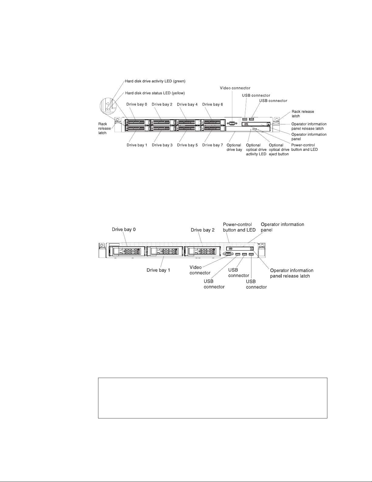
Note: The illustrations in this document might differ slightly from your model.
The following illustration shows the 2.5-inch hot-swap server models with an
optional optical drive bay.
Figure 1. Front view: 2.5-inch model
The following illustration shows the 3.5-inch hot-swap or simple-swap server
models. The servers support up to three 3.5-inch hot-swap SAS/SATA or
simple-swap SATA hard disk drives.
Figure 2. Front view: 3.5-inch model
If firmware and documentation updates are available, you can download them
from the IBM website. The server might have features that are not described in the
documentation that comes with the server, and the documentation might be
updated occasionally to include information about those features, or technical
updates might be available to provide additional information that is not included
in the server documentation. To check for updates, go to http://www.ibm.com/
supportportal/.
Record information about the server in the following table.
Product name IBM System x3550 M4 server
Machine type 7914
Model number _____________________________________________
Serial number _____________________________________________
The model number and serial number are on the ID label on the front of the
server, as shown in the following illustration.
2 IBM System x3550 M4 Type 7914: Installation and Service Guide
Page 21
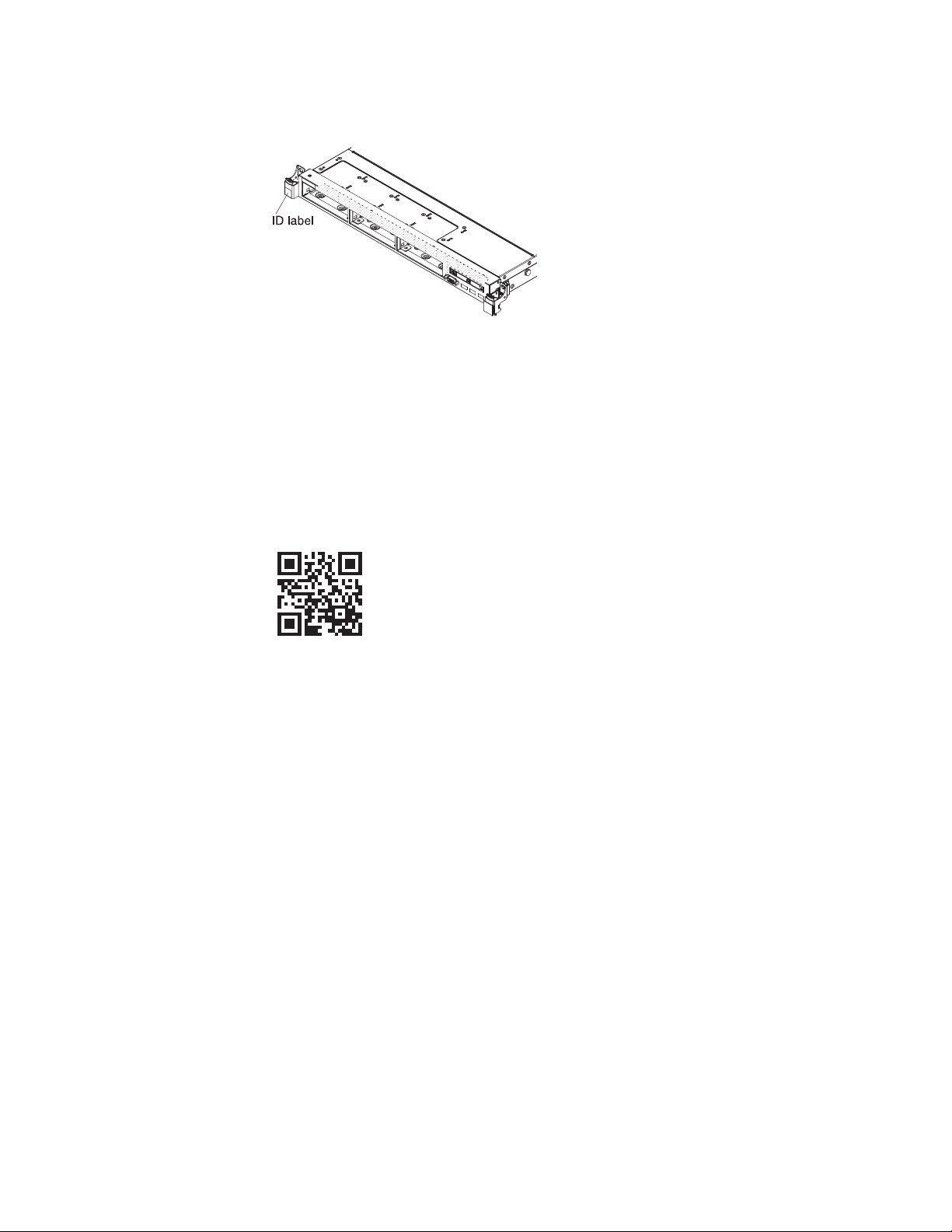
Note: The illustrations in this document might differ slightly from your hardware.
Figure 3. ID label
In addition, the system service label, which is on the cover of the server, provides a
QR code for mobile access to service information. You can scan the QR code using
a QR code reader and scanner with a mobile device and get quick access to the
IBM Service Information website. The IBM Service Information website provides
additional information for parts installation and replacement videos, and error
codes for server support.
The following illustration shows the QR code (http://ibm.co/114FFrw):
Figure 4. QR code
You can download an IBM ServerGuide Setup and Installation CD to help you
configure the hardware, install device drivers, and install the operating system.
For a list of supported optional devices for the server, see http://www.ibm.com/
systems/info/x86servers/serverproven/compat/us/.
See the Rack Installation Instructions document on the IBM System x Documentation
CD for complete rack installation and removal instructions.
Chapter 1. The IBM System x3550 M4 server 3
Page 22

The IBM Documentation CD
The IBM Documentation CD contains documentation for the server in Portable
Document Format (PDF) and includes the IBM Documentation Browser to help
you find information quickly.
Hardware and software requirements
The IBM Documentation CD requires the following minimum hardware and
software:
v Microsoft Windows XP, Windows 2000, or Red Hat Linux
v 100 MHz microprocessor
v 32 MB of RAM
v Adobe Acrobat Reader 3.0 (or later) or xpdf, which comes with Linux operating
systems
Using the Documentation Browser
Use the Documentation Browser to browse the contents of the CD, read brief
descriptions of the documents, and view documents, using Adobe Acrobat Reader
or xpdf.
The Documentation Browser automatically detects the regional settings in use in
your server and displays the documents in the language for that region (if
available). If a document is not available in the language for that region, the
English-language version is displayed.
Use one of the following procedures to start the Documentation Browser:
v If Autostart is enabled, insert the CD into the CD or DVD drive. The
Documentation Browser starts automatically.
v If Autostart is disabled or is not enabled for all users, use one of the following
procedures:
– If you are using a Windows operating system, insert the CD into the CD or
DVD drive and click Start > Run.IntheOpen field, type
e:\win32.bat
where e is the drive letter of the CD or DVD drive, and click OK.
– If you are using Red Hat Linux, insert the CD into the CD or DVD drive;
then, run the following command from the /mnt/cdrom directory:
sh runlinux.sh
Select the server from the Product menu. The Available Topics list displays all the
documents for the server. Some documents might be in folders. A plus sign (+)
indicates each folder or document that has additional documents under it. Click
the plus sign to display the additional documents.
When you select a document, a description of the document is displayed under
Topic Description. To select more than one document, press and hold the Ctrl key
while you select the documents. Click View to view the selected document or
documents in Acrobat Reader or xpdf. If you selected more than one document, all
the selected documents are opened in Acrobat Reader or xpdf.
4 IBM System x3550 M4 Type 7914: Installation and Service Guide
Page 23

To search all the documents, type a word or word string in the Search field and
click Search. The documents in which the word or word string appears are listed
in order of the most occurrences. Click a document to view it, and press Crtl+F to
use the Acrobat search function, or press Alt+F to use the xpdf search function
within the document.
Click Help for detailed information about using the Documentation Browser.
Related documentation
This Installation and Service Guide contains general information about the server
including how to set up and cable the server, how to install supported optional
devices, how to configure the server, and information to help you solve problems
yourself and information for service technicians. The following documentation also
comes with the server:
v Environmental Notices and User Guide
This document is in PDF format on the IBM Documentation CD. It contains
translated environmental notices.
v IBM License Agreement for Machine Code
This document is in PDF format on the IBM Documentation CD. It provides
translated versions of the IBM License Agreement for Machine Code for your
product.
v Important Notices
This document is in printed format and comes with the server. It contains
information about the safety, environmental, and electronic emission notices for
your IBM product.
v Licenses and Attributions Documents
This document is in PDF format on the IBM Documentation CD. It provides the
open source notices.
v Rack Installation Instructions
This printed document contains instructions for installing the server in a rack
and comes with the rack kit.
v Rack Safety Information
This multilingual document provides translated versions of the caution and
danger statements that appear in the rack documentation. Each caution and
danger statement has an assigned number, which you can use to locate the
corresponding statement in your native language.
v Safety Information
This document is in PDF format on the IBM Documentation CD. It contains
translated caution and danger statements. Each caution and danger statement
that appears in the documentation has a number that you can use to locate the
corresponding statement in your language in the Safety Information document.
v Safety Information Labels
This document provides the Simplified Chinese, Mongolian, Tibetan, Uygur, and
Zhuang translated versions of the product safety labels.
v Warranty Information
This document is in printed format and comes with the server. It contains
warranty terms and a pointer to the IBM Statement of Limited Warranty on the
IBM website.
Chapter 1. The IBM System x3550 M4 server 5
Page 24

Depending on the server model, additional documentation might be included on
the IBM Documentation CD.
The ToolsCenter for System x and BladeCenter is an online information center that
contains information about tools for updating, managing, and deploying firmware,
device drivers, and operating systems. The ToolsCenter for System x and
BladeCenter is at http://publib.boulder.ibm.com/infocenter/toolsctr/v1r0/.
The server might have features that are not described in the documentation that
you received with the server. The documentation might be updated occasionally to
include information about those features, or technical updates might be available
to provide additional information that is not included in the server documentation.
These updates are available from the IBM website. To check for updates, go to
http://www.ibm.com/supportportal/.
Notices and statements in this document
The caution and danger statements in this document are also in the multilingual
Safety Information document, which is on the IBM System x Documentation CD. Each
statement is numbered for reference to the corresponding statement in your
language in the Safety Information document.
The following notices and statements are used in this document:
v Note: These notices provide important tips, guidance, or advice.
v Important: These notices provide information or advice that might help you
avoid inconvenient or problem situations.
v Attention: These notices indicate potential damage to programs, devices, or data.
An attention notice is placed just before the instruction or situation in which
damage might occur.
v Caution: These statements indicate situations that can be potentially hazardous
to you. A caution statement is placed just before the description of a potentially
hazardous procedure step or situation.
v Danger: These statements indicate situations that can be potentially lethal or
extremely hazardous to you. A danger statement is placed just before the
description of a potentially lethal or extremely hazardous procedure step or
situation.
Server features and specifications
The following information is a summary of the features and specifications of the
server.
Depending on the model, some features might not be available, or some
specifications might not apply.
6 IBM System x3550 M4 Type 7914: Installation and Service Guide
Page 25

Table 1. Server features and specifications
Microprocessor (depending on the
model):
v Supports up to two multi-core
Memory (depending on the model):
v Minimum: 2 GB
v Maximum: 768 GB
microprocessors (one installed)
v Level-3 cache
v Two QuickPath Interconnect (QPI)
links speed up to 8.0 GT per
second
Notes:
v Type:
v Use the Setup utility program to
determine the type and speed of
the microprocessors.
v For a list of supported
microprocessors, see
http://www.ibm.com/systems/
info/x86servers/serverproven/
compat/us/.
v Slots: 24 dual inline
v Supports (depending on the
– 64 GB using unbuffered DIMMs
(UDIMMs)
– 384 GB using registered DIMMs
(RDIMMs)
– 768 GB using load reduction
DIMMs (LRDIMMs)
– PC3-8500 (DDR3-1066),
PC3-10600 (DDR3-1333),
PC3-12800 (DDR3-1600), or
PC3-14900 (DDR3-1866)
– Single-rank, dual-rank, or
quad-rank
– Registered DIMM (RDIMM),
unbuffered DIMM (UDIMM), or
load reduced DIMM (LRDIMM)
model):
– 4 GB UDIMM
– 2 GB, 4 GB, 8 GB, and 16 GB
RDIMMs
– 32 GB LRDIMM
SATA optical drives (optional for
2.5-inch models):
v DVD-ROM
v Multi-burner
Hard disk drive expansion bays
(depending on the model):
v 2.5-inch models: Up to eight
2.5-inch hot-swap SAS/SATA hard
disk drive bays (with an optional
optical drive bay)
v 3.5-inch models: Up to three
3.5-inch hot-swap SAS/SATA or
simple-swap SATA hard disk drive
bays
PCI expansion slots:
Supports two PCI riser slots:
v Slot 1 supports low-profile cards.
– PCI Express 3.0 x16
v Slot 2 supports half-length,
full-height cards.
– PCI Express 3.0 x8
– PCI Express 3.0 x16 (two
microprocessors installed)
– PCI-X 64-bit/133 MHz
Chapter 1. The IBM System x3550 M4 server 7
Page 26

Table 1. Server features and specifications (continued)
Video controller (integrated into
IMM2):
v Matrox G200eR2
Note: The maximum video
resolution is 1600 x 1200 at 75 Hz.
– SVGA compatible video
controller
– DDR3 528 MHz SDRAM video
memory controller
– Avocent Digital Video
Compression
– 16 MB of video memory (not
expandable)
Hot-swap fans:
v One microprocessor: 4 dual-motor
hot-swap fans.
v Two microprocessors: 6 dual-motor
hot-swap fans.
Power supply:
v Up to two hot-swap power
supplies for redundancy support
– 550-watt ac
– 750-watt ac
– 750-watt dc
Note: Power supplies in the server
must be with the same power rating
or wattage.
Integrated functions:
v Integrated Management Module II
(IMM2), which consolidates
multiple management functions in
a single chip.
v Intel I350AM4 Quad Port Gigabit
Ethernet controller with Wake on
LAN support
v Eight Universal Serial Bus (USB)
ports for 3.5-inch models. Seven
Universal Serial Bus (USB) ports
for 2.5-inch models. One port is for
optional USB flash device with
embedded hypervisor software is
installed.
v Six network ports (four 1 Gb
Ethernet ports on the system board
and two additional ports when the
optional IBM Dual-Port 10 Gb
Network Adapter is installed)
v One System Management 1 Gb
Ethernet port on the rear connected
to a systems management network.
This system management
connector is dedicated to the IMM2
functions.
v One serial port
RAID controllers (depending on the
model):
v A ServeRAID H1110 SAS/SATA
adapter that provides RAID 0, 1,
and 10.
v A ServeRAID M1115 SAS/SATA
adapter that provides RAID 0, 1,
and 10 with optional FoD RAID
5/50 and SED (Self Encrypting
Drive) upgrade.
v A ServeRAID M5110 SAS/SATA
adapter that provides RAID 0, 1,
and 10. Optional upgrade:
– RAID 5/50 (512 MB Cache) with
optional FoD RAID 6/60 and
SED upgrade
– RAID 5/50 (512 MB Flash) with
optional FoD RAID 6/60 and
SED upgrade
– RAID 5/50 (1 GB Flash) with
optional FoD RAID 6/60 and
SED upgrade
– RAID 5/50 and SED (Zero
Cache)
v A ServeRAID M5120 SAS/SATA
adapter that provides RAID 0, 1,
and 10. Optional upgrade:
– RAID 5/50 (512 MB Cache) with
optional FoD RAID 6/60 and
SED upgrade
– RAID 5/50 (512 MB Flash) with
optional FoD RAID 6/60 and
SED upgrade
– RAID 5/50 (1 GB Flash) with
optional FoD RAID 6/60 and
SED upgrade
– RAID 5/50 and SED (Zero
Cache)
8 IBM System x3550 M4 Type 7914: Installation and Service Guide
Page 27

Table 1. Server features and specifications (continued)
Environment: compliant with
ASHRAE class A3 specifications.
Server on:
v Temperature:
– 5°C to 40°C (41°F to 104°F)
– Altitude: 0 to 950 m (3,117 ft);
decrease the maximum system
temperature by 1°C for every
175-m increase in altitude.
v Maximum altitude: 3,050 m (10,000
ft), 5°C to 28°C (41°F to 82.4°F)
v Humidity:
– Non-condensing: -12°C dew
point (10.4°F)
– Relative humidity: 8% to 85%
v Maximum dew point: 24°C (75.2°F)
v Maximum rate of temperature
change:
– Tape drives: 5°C/hr (41°F/hr)
– Hard disk drives: 20°C/hr
(68°F/hr)
Server off:
v Temperature: 5°C to 45°C (41°F to
113°F)
v Relative humidity: 8% to 85%
v Maximum dew point: 27°C (80.6°F)
Storage (non-operating):
v Temperature: 1°C to 60°C (33.8°F to
140°F)
v Maximum altitude: 3,050 m (10,000
ft)
v Relative humidity: 5% to 80%
v Maximum dew point: 29°C (84.2°F)
Shipment (non-operating):
v Temperature: -40°C to 60°C (-40°F
to 140°F)
v Maximum altitude: 10,700 m
(35,105 ft)
v Relative humidity: 5% to 100%
v Maximum dew point: 29°C (84.2°F)
Particulate contamination: airborne
particulates and reactive gases acting
alone or in combination with other
environmental factors such as
humidity or temperature might pose
a risk to the server. For information
about the limits for particulates and
gases, see “Particulate
contamination” on page 835.
Attention:
v Design to ASHRAE Class A3,
ambient of 40°C, with relaxed
support:
– Support cloud like workload
with no performance
degradation acceptable
(Turbo-Off)
– Under no circumstance, can any
combination of worst case
workload and configuration
result in system shutdown or
design exposure at 40°C
v Specific microprocessors supported
environment:
– Microprocessor Intel Xeon
E5-2690, 135W:
- Temperature: 10°C to 27°C
(50°F to 80.6°F)
- Altitude: 0 to 304.8 m (1,000
ft)
– Microprocessor models with
115W and 130W:
- Temperature: 10°C to 35°C
(50°F to 95°F)
- Altitude: 0 to 914.4 m (3,000
ft)
Size:
v 1U
v Height: 43 mm (1.7 inches)
v Depth: 734 mm (28.9 inches)
v Width: 429 mm (16.9 inches)
v Weight: approximately 16.4 kg
(36.16 lb) when fully configured
Acoustical noise emissions:
v Sound power, idling: 6.5 bels
maximum
v Sound power, operating: 6.5 bels
maximum
Heat output:
Approximate heat output:
v Minimum configuration: 461 Btu
per hour (AC 135 watts)
v Maximum configuration: 3378 Btu
per hour (AC 990 watts)
Electrical input:
v Sine-wave input (50 - 60 Hz)
required
v Input voltage low range:
– Minimum: 100 V ac
– Maximum: 127 V ac
v Input voltage high range:
– Minimum: 200 V ac
– Maximum: 240 V ac
v Input kilovolt-amperes (kVA),
approximately:
– Minimum: 0.14 kVA
– Maximum: 0.993 kVA
Notes:
1. Power consumption and heat
output vary depending on the
number and type of optional
features installed and the
power-management optional
features in use.
2. The noise emission level stated is
the declared (upper limit) sound
power level, in bels, for a random
sample of machines. All
measurements are made in
accordance with ISO 7779 and
reported in conformance with ISO
9296. Actual sound-pressure levels
in a given location might exceed
the average values stated because
of room reflections and other
nearby noise sources. The noise
emission level stated in the
declared (upper limit)
sound-power level, in bels, for a
random sample of system.
EU Regulation 617/2013 Technical Documentation:
International Business Machines Corporation
New Orchard Road
Armonk, New York 10504
Chapter 1. The IBM System x3550 M4 server 9
Page 28

http://www.ibm.com/customersupport/
For more information on the energy efficiency program, go to
http://www.ibm.com/systems/x/hardware/energy-star/index.html
Product Type:
Computer server
Year first manufactured:
2012
Internal/external power supply efficiency:
v http://www.plugloadsolutions.com/psu_reports/
IBM_FSA011_550W_SO-301_Report.pdf
v http://www.plugloadsolutions.com/psu_reports/IBM_7001676-
XXXX_550W_SO-458_Report.pdf
v http://www.plugloadsolutions.com/psu_reports/IBM_7001605-
XXXX_750W_SO-258_Report.pdf
v http://www.plugloadsolutions.com/psu_reports/SO-299_IBM_DPS-
750AB-1_750W_Report.pdf
v http://www.plugloadsolutions.com/psu_reports/IBM_DPS-750AB-14
%20A_750W_SO-527_Report.pdf
Maximum power (watts):
See Power supply.
Idle state power (watts):
219
Sleep mode power (watts):
Not applicable for servers.
Off mode power (watts):
17
Noise levels (the declared A-weighed sound power level of the computer):
See Acoustical noise emissions.
Test voltage and frequency:
230V/50Hzor60Hz
Total harmonic distortion of the electricity supply system:
The maximum harmonic content of the input voltage waveform will be
equal or less than 2%. The qualification is compliant with EN 61000-3-2.
Information and documentation on the instrumentation set-up and circuits used
for electrical testing:
ENERGY STAR Test Method for Computer Servers; ECOVA Generalized
Test Protocol for Calculating the Energy Efficiency of Internal Ac-Dc and
Dc-Dc Power Supplies.
Measurement methodology used to determine information in this document:
ENERGY STAR Servers Version 2.0 Program Requirements; ECOVA
Generalized Test Protocol for Calculating the Energy Efficiency of Internal
Ac-Dc and Dc-Dc Power Supplies.
10 IBM System x3550 M4 Type 7914: Installation and Service Guide
Page 29

What your server offers
This section introduces features and technologies the server uses and provides.
v Active Energy Manager
The IBM Active Energy Manager solution is an IBM Systems Director plug-in
that measures and reports server power consumption as it occurs. This enables
you to monitor power consumption in correlation to specific software
application programs and hardware configurations. You can obtain the
measurement values through the systems-management interface and view them,
using IBM Systems Director. For more information, including the required levels
of IBM Systems Director and Active Energy Manager, see the IBM Systems
Director Information Center at http://pic.dhe.ibm.com/infocenter/director/
pubs/index.jsp?topic=%2Fcom.ibm.director.main.helps.doc%2Ffqm0_main.html
or see http://www.ibm.com/systems/management/director/downloads.html.
v Dynamic System Analysis (DSA)
The server comes with the IBM Dynamic System Analysis (DSA) Preboot
diagnostic program. DSA collects and analyzes system information to aid in
diagnosing server problems, as well as offering a rich set of diagnostic tests of
the major components of the server. DSA creates a DSA log, which is a
chronologically ordered merge of the system-event log (as the IPMI event log),
the integrated management module (IMM) event log (as the ASM event log),
and the operating-system event logs. You can send the DSA log as a file to IBM
Support or view the information as a text file or HTML file.
Two editions of Dynamic System Analysis are available: DSA Portable and DSA
Preboot. For more information about both editions, see “DSA editions” on page
150.
v Features on Demand
If a Features on Demand feature is integrated in the server or in an optional
device that is installed in the server, you can purchase an activation key to
activate the feature. For information about Features on Demand, see
/http://www.ibm.com/systems/x/fod/.
v IBM ServerGuide Setup and Installation CD
The ServerGuide Setup and Installation CD, which you can download from the
web, provides programs to help you set up the server and install a Windows
operating system. The ServerGuide program detects installed optional hardware
devices and provides the correct configuration programs and device drivers. For
more information about the ServerGuide Setup and Installation CD, see “Using the
ServerGuide Setup and Installation CD” on page 104.
v IBM Systems Director
IBM Systems Director is a platform-management foundation that streamlines the
way you manage physical and virtual systems in a heterogeneous environment.
By using industry standards, IBM Systems Director supports multiple operating
systems and virtualization technologies. For more information, see the IBM
Systems Director Information Center at http://pic.dhe.ibm.com/infocenter/
director/pubs/index.jsp?topic=%2Fcom.ibm.director.main.helps.doc
%2Ffqm0_main.html and “IBM Systems Director” on page 15.
v Integrated Management Module II (IMM2)
The integrated management module II (IMM2) combines service processor
functions, video controller, and remote presence and blue-screen capture features
in a single chip. The IMM provides advanced service-processor control,
monitoring, and alerting function. If an environmental condition exceeds a
threshold or if a system component fails, the IMM lights LEDs to help you
diagnose the problem, records the error in the IMM event log, and alerts you to
Chapter 1. The IBM System x3550 M4 server 11
Page 30

the problem. Optionally, the IMM also provides a virtual presence capability for
remote server management capabilities. The IMM provides remote server
management through the following industry-standard interfaces:
– Intelligent Platform Management Interface (IPMI) version 2.0
– Simple Network Management Protocol (SNMP) version 3.0
– Common Information Model (CIM)
– Web browser
Some of the features that are unique to the IMM are enhanced performance,
higher-resolution remote video, expanded security options, and Feature on
Demand enablement for hardware and firmware options.
For additional information, see “Using the integrated management module” on
page 114 and the Integrated Management Module II User’s Guide at
http://www.ibm.com/support/entry/portal/docdisplay?lndocid=MIGR-
5086346.
v Integrated network support
The server comes with an integrated dual-port Intel Gigabit Ethernet controller,
which supports connection to a 10 Mbps, 100 Mbps, or 1000 Mbps network. For
more information, see “Configuring the Ethernet controller” on page 119.
v Integrated Trusted Platform Module (TPM)
This integrated security chip performs cryptographic functions and stores
private and public secure keys. It provides the hardware support for the Trusted
Computing Group (TCG) specification. You can download the software to
support the TCG specification, when the software is available. You can enable
TPM support through the Setup utility under the System Security menu option.
v Large data-storage capacity and hot-swap capability
The hot-swap server models support a maximum of eight 2.5-inch or three
3.5-inch hot-swap Serial Attached SCSI (SAS) hard disk drives or hot-swap Serial
ATA (SATA) hard disk drives. The simple-swap server models support a
maximum of three 3.5-inch simple-swap SATA hard disk drives.
With the hot-swap feature, you can add, remove, or replace hard disk drives
without turning off the server.
v Large system-memory capacity
The server can support up to 768 GB of system memory. The server provides 24
dual inline memory module (DIMM) connectors. The server memory controller
supports error correcting code (ECC) for PC3-8500 (DDR3-1066), PC3-10600
(DDR3-1333), PC3-12800 (DDR3-1600), or PC3-14900 (DDR3-1866), DDR3
(third-generation double-data-rate), synchronous dynamic random access
memory (SDRAM) DIMMs.
v Light path diagnostics
Light path diagnostics provides LEDs to help you diagnose problems. For more
information about light path diagnostics and the LEDs, see “Light path
diagnostics” on page 134 and “Light path diagnostics LEDs” on page 137.
v Mobile access to IBM Service Information website
The server provides a QR code on the system service label, which is on the
cover of the server, that you can scan using a QR code reader and scanner with
a mobile device to get quick access to the IBM Service Information website. The
IBM Service Information website provides additional information for parts
installation and replacement videos, and error codes for server support. For the
QR code, see QR code information on page Chapter 1, “The IBM System x3550
M4 server,” on page 1.
v Multi-core processing
12 IBM System x3550 M4 Type 7914: Installation and Service Guide
Page 31

The server supports up to two multi-core microprocessors. The server comes
with a minimum of one microprocessor.
v PCI adapter capabilities
The server has two PCI interface slots (one supports low-profile cards, and one
supports half-length, full-height cards). Slot 2 can support PCI Express or PCI-X
adapters through an optional PCI riser card. See “Replacing an adapter” on page
250 for detailed information.
v Redundant connection
The addition of the optional Ethernet adapter provides failover capability to a
redundant Ethernet connection with the applicable application installed. If a
problem occurs with the primary Ethernet connection and the optional Ethernet
adapter is installed on the server, all Ethernet traffic that is associated with the
primary connection is automatically switched to the optional redundant Ethernet
adapter connection. If the applicable device drivers are installed, this switching
occurs without data loss and without user intervention.
v Redundant cooling and optional power capabilities
The server supports a maximum of two 550-watt or 750-watt hot-swap power
supplies and six dual-motor hot-swap fans, which provide redundancy and
hot-swap capability for a typical configuration. The redundant cooling by the
fans in the server enables continued operation if one of the fans fails. The server
comes with the minimum of one 550-watt or 750-watt hot-swap power supply
and four fans.
You must install the fourth and sixth fans when you install the second
microprocessor in the server. You can order the second optional power supply
for power redundancy.
Note: You cannot mix 550-watt and 750-watt power supplies in the server.
v ServeRAID support
The ServeRAID adapter provides hardware redundant array of independent
disks (RAID) support to create configurations. The standard RAID adapter
provides RAID levels 0, 1, and 10. An optional RAID adapter is available for
purchase.
v Systems-management capabilities
The server comes with an integrated management module II (IMM2). When the
IMM is used with the systems-management software that comes with the server,
you can manage the functions of the server locally and remotely. The IMM also
provides system monitoring, event recording, and network alert capability. The
systems-management connector on the rear of the server is dedicated to the
IMM. The dedicated systems-management connector provides additional
security by physically separating the management network traffic from the
production network. You can use the Setup utility to configure the server to use
a dedicated systems-management network or a shared network.
v UEFI-compliant server firmware
IBM System x Server Firmware (server firmware) offers several features,
including Unified Extensible Firmware Interface (UEFI) 2.1 compliance; Active
Energy Manager technology; enhanced reliability, availability, and serviceability
(RAS) capabilities; and basic input/output system (BIOS) compatibility support.
UEFI replaces the BIOS and defines a standard interface between the operating
system, platform firmware, and external devices. UEFI-compliant System x
servers are capable of booting UEFI-compliant operating systems, BIOS-based
operating systems, and BIOS-based adapters as well as UEFI-compliant adapters.
Note: The server does not support DOS (Disk Operating System).
Chapter 1. The IBM System x3550 M4 server 13
Page 32

v VMware ESXi embedded hypervisor
An optional USB flash device with VMware ESXi embedded hypervisor software
is available for purchase. Hypervisor is virtualization software that enables
multiple operating systems to run on a host system at the same time. The USB
embedded hypervisor flash device can be installed in the internal USB connector
on the system board. For more information about using the embedded
hypervisor, see “Using the embedded hypervisor” on page 118.
Reliability, availability, and serviceability
Three important computer design features are reliability, availability, and
serviceability (RAS). The RAS features help to ensure the integrity of the data that
is stored in the server, the availability of the server when you need it, and the ease
with which you can diagnose and correct problems.
Your server has the following RAS features:
v 3-year parts and 3-year labor limited warranty (Machine Type 7914)
v 24-hour support center
v Automatic error retry and recovery
v Automatic restart on nonmaskable interrupt (NMI)
v Automatic restart after a power failure
v Back up basic input/output system switching under the control of the integrated
management module (IMM)
v Built-in monitoring for fan, power, temperature, voltage, and power-supply
redundancy
v Cable-presence detection on most connectors
v Chipkill memory protection
v Double-device data correction (DDDC) for x4 DRAM technology DIMMs
(available on 16 GB DIMMs only). Ensures that data is available on a single x4
DRAM DIMM after a hard failure of up to two DRAM DIMMs. One x4 DRAM
DIMM in each rank is reserved as a space device.
v Diagnostic support for ServeRAID and Ethernet adapters
v Error codes and messages
v Error correcting code (ECC) L3 cache and system memory
v Full Array Memory Mirroring (FAMM) redundancy
v Hot-swap cooling fans with speed-sensing capability
v Hot-swap hard disk drives
v Information and light path diagnostics LED panels
v Integrated Management Module (IMM)
v Light path diagnostics LEDs for memory DIMMs, microprocessors, hard disk
drives, solid state drives, power supplies, and fans
v Memory mirroring and memory sparing support
v Memory error correcting code and parity test
v Memory down sizing (non-mirrored memory). After a restart of the server after
the memory controller detected a non-mirrored uncorrectable error and the
memory controller cannot recover operationally, the IMM logs the uncorrectable
error and informs POST. POST logically maps out the memory with the
uncorrectable error, and the server restarts with the remaining installed memory.
v Menu-driven setup, system configuration, and redundant array of independent
disks (RAID) configuration programs
v Microprocessor built-in self-test (BIST), internal error signal monitoring, internal
thermal trip signal monitoring, configuration checking, and microprocessor and
voltage regulator module failure identification through light path diagnostics
v Nonmaskable interrupt (NMI) button
v Parity checking on the small computer system interface (SCSI) bus and PCI-E
and PCI/PCI-X buses
14 IBM System x3550 M4 Type 7914: Installation and Service Guide
Page 33

v Power management: Compliance with Advanced Configuration and Power
Interface (ACPI)
v Power-on self-test (POST)
v Predictive Failure Analysis (PFA) alerts on memory, microprocessors, SAS/SATA
hard disk drives or solid state drives, fans, power supplies, and VRM
v Redundant Ethernet capabilities with failover support
v Redundant hot-swap power supplies and redundant hot-swap fans
v Redundant network interface card (NIC) support
v Remind button to temporarily turn off the system-error LED
v Remote system problem-determination support
v ROM-based diagnostics
v ROM checksums
v Serial Presence Detection (SPD) on memory, VPD on system board, power
supply, and hard disk drive or solid state drive backplanes, microprocessor and
memory expansion tray, and Ethernet cards
v Single-DIMM isolation of excessive correctable error or multi-bit error by the
Unified Extensible Firmware Interface (UEFI)
v Solid state drives
v Standby voltage for system-management features and monitoring
v Startup (boot) from LAN through remote initial program load (RIPL) or dynamic
host configuration protocol/boot protocol (DHCP/BOOTP)
v System auto-configuring from the configuration menu
v System-error logging (POST and IMM)
v Systems-management monitoring through the Inter-Integrated Circuit (IC)
protocol bus
v Uncorrectable error (UE) detection
v Upgradeable POST, Unified Extensible Firmware Interface (UEFI), diagnostics,
IMM firmware, and read-only memory (ROM) resident code, locally or over the
LAN
v Vital product data (VPD) on microprocessors, system board, power supplies, and
SAS/SATA (hot-swap hard disk drive or solid state drive) backplane
v Wake on LAN capability
IBM Systems Director
IBM Systems Director is a platform-management foundation that streamlines the
way you manage physical and virtual systems supports multiple operating systems
and virtualization technologies in IBM and non-IBM x86 platforms.
Through a single user interface, IBM Systems Director provides consistent views
for viewing managed systems, determining how these systems relate to one other,
and identifying their statuses, helping to correlate technical resources with business
needs. A set of common tasks that are included with IBM Systems Director
provides many of the core capabilities that are required for basic management,
which means instant out-of-the-box business value. The common tasks include the
following items:
v Discovery
v Inventory
v Configuration
v System health
v Monitoring
v Updates
v Event notification
v Automation for managed systems
Chapter 1. The IBM System x3550 M4 server 15
Page 34

The IBM Systems Director Web and command-line interfaces provide a consistent
interface that is focused on driving these common tasks and capabilities:
v Discovering, navigating, and visualizing systems on the network with the
detailed inventory and relationships to the other network resources
v Notifying users of problems that occur on systems and the ability to isolate the
sources of the problems
v Notifying users when systems need updates and distributing and installing
updates on a schedule
v Analyzing real-time data for systems and setting critical thresholds that notify
the administrator of emerging problems
v Configuring settings of a single system and creating a configuration plan that
can apply those settings to multiple systems
v Updating installed plug-ins to add new features and functions to the base
capabilities
v Managing the life cycles of virtual resources
For more information about IBM Systems Director, see the documentation on the
IBM Systems Director DVD that comes with the server, the IBM Systems Director
Information Center at http://pic.dhe.ibm.com/infocenter/director/pubs/
index.jsp?topic=%2Fcom.ibm.director.main.helps.doc%2Ffqm0_main.html, and the
Systems Management website at http://www.ibm.com/systems/management/,
which presents an overview of IBM Systems Management and IBM Systems
Director.
Server controls, LEDs, and power
This section describes the controls and light-emitting diodes (LEDs) and how to
turn the server on and off.
For the locations of other LEDs on the system board, see “System-board LEDs” on
page 32.
Front view
The following illustrations show the controls, LEDs, and connectors on the front of
your server model.
2.5-inch hard disk drive server model.
Figure 5. Front view: 2.5-inch
3.5-inch hard disk drive server model.
16 IBM System x3550 M4 Type 7914: Installation and Service Guide
Page 35

Figure 6. Front view: 3.5-inch
v Rack release latches: Press the latches on each front side of the server to remove
the server from the rack.
v Hard disk drive activity LEDs: This LED is used on hot-swap SAS or SATA
hard disk drives. Each hot-swap hard disk drive has an activity LED, and when
this LED is flashing, it indicates that the drive is in use.
v Hard disk drive status LEDs: This LED is used on hot-swap SAS or SATA hard
disk drives. When this LED is lit, it indicates that the drive has failed. If an
optional IBM ServeRAID controller is installed in the server, when this LED is
flashing slowly (one flash per second), it indicates that the drive is being rebuilt.
When the LED is flashing rapidly (three flashes per second), it indicates that the
controller is identifying the drive.
v Optional DVD eject button: Press this button to release a DVD or CD from the
optional DVD drive.
v Optional DVD drive activity LED: When this LED is lit, it indicates that the
optional DVD drive is in use.
v Operator information panel: This panel contains controls and LEDs that provide
information about the status of the server. For information about the controls
and LEDs on the operator information panel, see “Operator information panel”
on page 18.
v Operator information panel release latch: Press the blue release latch to pull out
the light path diagnostics panel and view the light path diagnostics LEDs and
buttons. See “Light path diagnostics panel” on page 19 for more information
about the light path diagnostics.
v Video connector: Connect a monitor to this connector. The video connectors on
the front and rear of the server can be used simultaneously.
Note: The maximum video resolution is 1600 x 1200 at 75 Hz.
v USB connectors: Connect a USB device, such as a USB mouse or keyboard to
any of these connectors.
Chapter 1. The IBM System x3550 M4 server 17
Page 36

Operator information panel
The following illustrations show the controls and LEDs on the advanced operator
information panel and the operator information panel depending on your server
model.
Figure 7. Advanced operator information panel
Figure 8. Operator information panel
v Power-control button and power-on LED: Press this button to turn the server
on and off manually. The states of the power-on LED are as follows:
Off: Power is not present or the power supply, or the LED itself has failed.
Flashing rapidly (4 times per second): The server is turned off and is not
ready to be turned on. The power-control button is disabled. This will last
approximately 5 to 10 seconds.
Flashing slowly (once per second): The server is turned off and is ready to
be turned on. You can press the power-control button to turn on the server.
Lit: The server is turned on.
v Ethernet activity LEDs: When any of these LEDs is lit, they indicate that the
server is transmitting to or receiving signals from the Ethernet LAN that is
connected to the Ethernet port that corresponds to that LED.
v System-locator button/LED: Use this blue LED to visually locate the server
among other servers. A system-locator LED is also on the rear of the server. This
LED is used as a presence detection button as well. You can use IBM Systems
Director or IMM web interface to light this LED remotely. This LED is controlled
by the IMM. The locator button is pressed to visually locate the server among
the others servers.
v Check log LED: When this yellow LED is lit, it indicates that a system error has
occurred. Check the event log for additional information. See “Event logs” on
page 146 for more information about event logs.
18 IBM System x3550 M4 Type 7914: Installation and Service Guide
Page 37

v System-error LED: When this yellow LED is lit, it indicates that a system error
has occurred. A system-error LED is also on the rear of the server. An LED on
the light path diagnostics panel on the operator information panel or on the
system board is also lit to help isolate the error. This LED is controlled by the
IMM.
Notes:
1. Depending on the type of operator information panel installed in your server,
the Reset button is on the operator information panel or the light path
diagnostics panel.
2. You don't have to pull out the operator information panel to obtain more
information if there's no release latch existed in your server model.
Light path diagnostics panel
The light path diagnostics panel is located on the top of the operator information
panel.
For additional information about the LEDs on the light path diagnostics panel, see
“Light path diagnostics LEDs” on page 137.
Note: The system service label inside the server cover also provides information
about the location of the light path diagnostics LEDs.
To access the light path diagnostics panel, press the blue release latch on the
operator information panel. Pull forward on the panel until the hinge of the
operator information panel is free of the server chassis. Then pull down on the
panel, so that you can view the light path diagnostics panel information.
Figure 9. Light path diagnostics panel exposure
Chapter 1. The IBM System x3550 M4 server 19
Page 38

The following illustration shows the LEDs and controls on the light path
diagnostics panel.
Figure 10. Light path diagnostics panel
v Remind button: This button places the system-error LED on the operator
information panel into Remind mode. In Remind mode, the system-error LED
flashes once every 2 seconds until the problem is corrected, the server is
restarted, or a new problem occurs.
By placing the system-error LED indicator in Remind mode, you acknowledge
that you are aware of the last failure but will not take immediate action to
correct the problem.
v Reset button: Press this button to reset the server and run the power-on self-test
(POST). You might have to use a pen or the end of a straightened paper clip to
press the button. The Reset button is in the lower-right corner of the light path
diagnostics panel.
Rear view
The following illustration shows the connectors on the rear of the server.
Figure 11. Rear view connectors
20 IBM System x3550 M4 Type 7914: Installation and Service Guide
Page 39

v NMI button: Press this button to force a nonmaskable interrupt to the
microprocessor. It allows you to blue screen the server and take a memory
dump (use this button only when directed by the IBM service support). You
might have to use a pen or the end of a straightened paper clip to press the
button. The NMI button is in the lower left-hand corner on the rear of the
server.
v PCI slot 1: Insert a low-profile PCI Express adapter into this slot.
v PCI slot 2: Insert a half-length, full-height PCI Express or PCI-X adapter into
this slot.
v Power connector: Connect the power cord to this connector.
Note: Power supply 1 is the default/primary power supply. If power supply 1
fails, you must replace it immediately.
v Video connector: Connect a monitor to this connector. The video connectors on
the front and rear of the server can be used simultaneously.
Note: The maximum video resolution is 1600 x 1200 at 75 Hz.
v Serial connector: Connect a 9-pin serial device to this connector. The serial port
is shared with the integrated management module II (IMM2). The IMM2 can
take control of the shared serial port to redirect serial traffic, using Serial over
LAN (SOL).
v USB connectors: Connect a USB device, such as a USB mouse or keyboard to
any of these connectors.
v Systems-management Ethernet connector: Use this connector to connect the
server to a network for full systems-management information control. This
connector is used only by the integrated management module (IMM2). A
dedicated management network provides additional security by physically
separating the management network traffic from the production network. You
can use the Setup utility to configure the server to use a dedicated systems
management network or a shared network.
v Ethernet connectors: Use either of these connectors to connect the server to a
network. When you enable shared Ethernet for IMM2 in the Setup utility, you
can access the IMM2 using either the Ethernet 1 or the system-management
Ethernet (default) connector.
The following illustration shows the LEDs on the rear of the server.
Figure 12. Rear view LEDs
The following illustration shows the LEDs on a dc power supply.
Chapter 1. The IBM System x3550 M4 server 21
Page 40

Figure 13. DC power supply LEDs
v Ethernet activity LEDs: When these LEDs are lit, they indicate that the server is
transmitting to or receiving signals from the Ethernet LAN that is connected to
the Ethernet port.
v Ethernet link LEDs: When these LEDs are lit, they indicate that there is an
active link connection on the 10BASE-T, 100BASE-TX, or 1000BASE-TX interface
for the Ethernet port.
v AC power LED: Each hot-swap ac power supply has an ac power LED. When
the ac power LED is lit, it indicates that sufficient power is coming into the
power supply through the power cord. During typical operation, the ac power
LED is lit. For any other combination of LEDs, see “AC power-supply LEDs” on
page 142.
v DC power LED: Each hot-swap ac power supply has a dc power LED. When
the dc power LED is lit, it indicates that the power supply is supplying adequate
dc power to the system. During typical operation, both the ac and dc power
LEDs are lit. For any other combination of LEDs, see “AC power-supply LEDs”
on page 142.
v IN OK power LED: Each hot-swap dc power supply has an IN OK power LED.
When the IN OK power LED is lit, it indicates that sufficient power is coming
into the power supply through the power cord. During typical operation, both
the IN OK and OUT OK power LEDs are lit. For any other combination of
LEDs, see “DC power-supply LEDs” on page 143.
v OUT OK power LED: Each hot-swap dc power supply has an OUT OK power
LED. When the OUT OK power LED is lit, it indicates that the power supply is
supplying adequate dc power to the system. During typical operation, both the
IN OK and OUT OK power LEDs are lit. For any other combination of LEDs,
see “DC power-supply LEDs” on page 143.
v Power-supply error LED: When the power-supply error LED is lit, it indicates
that the power supply has failed.
Note: Power supply 1 is the default/primary power supply. If power supply 1
fails, you must replace the power supply immediately.
v Power-on LED: When this LED is lit and not flashing, it indicates that the server
is turned on. The states of the power-on LED are as follows:
Off: Power is not present, or the power supply or the LED itself has failed.
Flashing rapidly (4 times per second): The server is turned off and is not
ready to be turned on. The power-control button is disabled. This will last
approximately 5 to 10 seconds.
22 IBM System x3550 M4 Type 7914: Installation and Service Guide
Page 41

Flashing slowly (once per second): The server is turned off and is ready to
be turned on. You can press the power-control button to turn on the server.
Lit: The server is turned on.
v System-locator LED: Use this LED to visually locate the server among other
servers. You can use IBM Systems Director or IMM2 web interface to light this
LED remotely.
v System-error LED: When this LED is lit, it indicates that a system error has
occurred. An LED on the light path diagnostics panel is also lit to help isolate
the error.
Server power features
When the server is connected to an ac power source but is not turned on, the
operating system does not run, and all core logic except for the integrated
management module is shut down.
However, the server can respond to requests from IMM, such as a remote request
to turn on the server. The power-on LED flashes to indicate that the server is
connected to an ac power source but is not turned on.
Turning on the server
Use this information to turn on the server.
Approximately 5 seconds after the server is connected to power, one or more fans
might start running to provide cooling while the server is connected to power and
the power-on button LED will blink quickly. Approximately 5 to 10 seconds after
the server is connected to power, the power-control button becomes active (the
power-on LED will blink slowly), and one or more fans might start running to
provide cooling while the server is connected to power. You can turn on the server
by pressing the power-control button.
The server can also be turned on in any of the following ways:
v If a power failure occurs while the server is turned on, the server will restart
automatically when power is restored.
v If your operating system supports the Wake on LAN feature, the Wake on LAN
feature can turn on the server.
Notes:
1. When 4 GB or more of memory (physical or logical) is installed, some memory
is reserved for various system resources and is unavailable to the operating
system. The amount of memory that is reserved for system resources depends
on the operating system, the configuration of the server, and the configured
PCI options.
2. Ethernet 1 connector supports Wake on LAN feature.
3. When you turn on the server with the graphical adapters installed, the IBM
logo displays on the screen after approximately 3 minutes. This is normal
operation while the system loads.
Chapter 1. The IBM System x3550 M4 server 23
Page 42

Turning off the server
Use this information to turn off the server.
When you turn off the server and leave it connected to power, the server can
respond to requests to the service processor, such as a remote request to turn on
the server. While the server remains connected to power, one or more fans might
continue to run. To remove all power from the server, you must disconnect it from
the power source.
Some operating systems require an orderly shutdown before you turn off the
server. See your operating-system documentation for information about shutting
down the operating system.
Statement 5
CAUTION:
The power control button on the device and the power switch on the power
supply do not turn off the electrical current supplied to the device. The device
also might have more than one power cord. To remove all electrical current from
the device, ensure that all power cords are disconnected from the power source.
2
1
The server can be turned off in any of the following ways:
v You can turn off the server from the operating system, if your operating system
supports this feature. After an orderly shutdown of the operating system, the
server will turn off automatically.
v You can press the power-control button to start an orderly shutdown of the
operating system and turn off the server, if your operating system supports this
feature.
v If the operating system stops functioning, you can press and hold the
power-control button for more than 4 seconds to turn off the server.
v The server can be turned off by Wake on LAN feature with the following
limitation:
Note: When you install any PCI adapter, the power cords must be disconnected
from the power source before you remove the PCI Express riser-card assembly
and the PCI-X riser-card assembly. Otherwise, the Wake on LAN feature might
not work.
v The Integrated Management Module (IMM) can turn off the server as an
automatic response to a critical system failure.
24 IBM System x3550 M4 Type 7914: Installation and Service Guide
Page 43

Chapter 2. Installing optional devices
This section provides detailed instructions for installing optional hardware devices
in the server.
In addition to the instructions in this chapter for installing optional hardware
devices, updating the firmware and device drivers, and completing the installation,
IBM Business Partners must also complete the steps in “Instructions for IBM
Business Partners” on page 26.
Important: To help ensure that the devices that you install work correctly and do
not introduce problems, observe the following precautions:
1. Make sure that the server and the installed firmware levels support the devices
that you are installing. If necessary, update the UEFI and IMM firmware and
any other firmware that is stored on the system board. For information about
where firmware is stored in the server, see “Updating the firmware” on page
101. For a list of supported optional devices for the server, see
http://www.ibm.com/systems/info/x86servers/serverproven/compat/us/.
2. Use the best practices to apply current firmware and device-driver updates for
the server and optional devices. To download the “IBM System x Firmware
Update Best Practices” document, go to www.ibm.com/support/entry/portal/
docdisplay?lndocid=MIGR-5082923&brandind=5000008. Additional hints and
tips are available from the following sites:
v IBM support: http://www.ibm.com/supportportal/
v System x configuration tools: http://www.ibm.com/systems/x/hardware/
configtools.html
3. Before you install optional hardware devices, make sure that the server is
working correctly. Start the server and make sure that the operating system
starts, if an operating system is installed, or that a 19990305 error code is
displayed, indicating that an operating system was not found but the server is
otherwise working correctly. If the server is not working correctly, see
“Running the DSA Preboot diagnostic programs” on page 151 for information
about how to run diagnostics.
4. Follow the installation procedures in this chapter and use the correct tools.
Incorrectly installed devices can cause system failure because of damaged pins
in sockets or connectors, loose cabling, or loose components.
© Copyright IBM Corp. 2012, 2014 25
Page 44

Instructions for IBM Business Partners
In addition to the instructions in this section for installing optional hardware
devices, updating firmware and device drivers, and completing the installation,
IBM Business Partners must also complete the following steps.
1. After you have confirmed that the server starts correctly and recognizes the
newly installed devices and that no error LEDs are lit, run the Dynamic System
Analysis (DSA) stress test. For information about using DSA, see “IBM
Dynamic System Analysis” on page 149.
2. Shut down and restart the server multiple times to ensure that the server is
correctly configured and functions correctly with the newly installed devices.
3. Save the DSA log as a file and send it to IBM. For information about
transferring data and logs, see “How to send DSA data to IBM.”
4. To ship the server, repackage it in the original undamaged packing material
and observe IBM procedures for shipping.
Support information for IBM Business Partners is available at http://
www.ibm.com/partnerworld/.
How to send DSA data to IBM
Use the IBM Enhanced Customer Data Repository to send diagnostic data to IBM.
Before you send diagnostic data to IBM, read the terms of use at
http://www.ibm.com/de/support/ecurep/terms.html.
You can use any of the following methods to send diagnostic data to IBM:
v Standard upload: http://www.ibm.com/de/support/ecurep/send_http.html
v Standard upload with the system serial number: http://www.ecurep.ibm.com/
app/upload_hw
v Secure upload: http://www.ibm.com/de/support/ecurep/
send_http.html#secure
v Secure upload with the system serial number: https://www.ecurep.ibm.com/
app/upload_hw
Server components
The following illustration shows the major components in the server.
The illustrations in this document might differ slightly from your hardware.
26 IBM System x3550 M4 Type 7914: Installation and Service Guide
Page 45

Figure 14. Server components
Blue on a component indicates touch points, where you can grip the component to
remove it from or install it in the server, open or close a latch, and so on.
Orange on a component or an orange label on or near a component indicates that
the component can be hot-swapped, which means that if the server and operating
system support hot-swap capability, you can remove or install the component
while the server is running. (Orange can also indicate touch points on hot-swap
components.) See the instructions for removing or installing a specific hot-swap
component for any additional procedures that you might have to perform before
you remove or install the component.
Chapter 2. Installing optional devices 27
Page 46

System-board internal connectors
The following illustration shows the internal connectors on the system board.
Figure 15. System-board internal connectors
System-board external connectors
The following illustration shows the external connectors on the system board.
28 IBM System x3550 M4 Type 7914: Installation and Service Guide
Page 47

Figure 16. System-board external connectors
System-board switches, jumpers, and buttons
The following illustration shows the location of the switches, jumpers, and buttons
on the server.
Important:
1. Before you change any switch settings or move any jumpers, turn off the
server; then, disconnect all power cords and external cables. Review the
information in “Safety” on page vii, “Installation guidelines” on page 33,
“Handling static-sensitive devices” on page 36, and “Turning off the server” on
page 24.
2. Any system-board switch or jumper block that is not shown in the illustrations
in this document are reserved.
3. If there is a clear protective sticker on the top of the switch blocks, you must
remove and discard it to access the switches.
Chapter 2. Installing optional devices 29
Page 48

Figure 17. System-board switches, jumpers, and buttons
The following table describes the jumpers on the system board.
Table 2. System board jumpers
Jumper number Jumper name Jumper setting
JP1 CMOS clear jumper
JP2 UEFI boot backup jumper
JP6 System TPM physical
presence jumper
Notes:
1. If no jumper is present, the server responds as if the pins are set to the default.
2. Changing the position of the UEFI boot backup jumper (JP2) from pins 1 and 2 to pins
2 and 3 before the server is turned on alters which flash ROM page is loaded. Do not
change the jumper pin position after the server is turned on. This can cause an
unpredictable problem.
v Pins 1 and 2: Normal (default).
v Pins 2 and 3: Clears the real-time
clock (RTC) registry.
v Pins 1 and 2: Normal (default).
Loads the primary server firmware
ROM page.
v Pins 2 and 3: Loads the secondary
(backup) server firmware ROM
page.
v Pins 1 and 2: Normal (default).
v Pins 2 and 3: Indicates a physical
presence to the system TPM.
30 IBM System x3550 M4 Type 7914: Installation and Service Guide
Page 49

The following table describes the functions of the SW3 switch block on the system
board.
Table 3. System board SW3 switch block definition
Switch
number Default position Description
1 Off Reserved.
2 Off Reserved.
3 Off Reserved.
4 Off Power-on password override. Changing the
position of this switch bypasses the power-on
password check the next time the server is turned
on and starts the Setup utility so that you can
change or delete the power-on password. You do
not have to move the switch back to the default
position after the power-on password in
overridden.
Changing the position of this switch does not affect
the administrator password check if an
administrator password is set.
See “Passwords” on page 111 for additional
information about passwords.
The following table describes the functions of the button on the system board.
Table 4. Button on the server
Button name Function
Force NMI button This button is on the rear of the server. Press
this button to force a nonmaskable interrupt
to the microprocessor. You might have to use
a pen or the end of a straightened paper clip
to press the button. You can also use it to
force a blue-screen memory dump (use this
button only when you are directed to do so
by IBM Support).
Chapter 2. Installing optional devices 31
Page 50

System-board LEDs
The following illustration shows the light-emitting diodes (LEDs) on the system
board.
Figure 18. System-board LEDs
System-board optional-device connectors
The following illustration shows the connectors on the system board for the
optional devices.
32 IBM System x3550 M4 Type 7914: Installation and Service Guide
Page 51

Figure 19. System-board optional-device connectors
Installation guidelines
Use this information for installation.
Attention: Static electricity that is released to internal server components when
the server is powered-on might cause the system to halt, which might result in the
loss of data. To avoid this potential problem, always use an electrostatic-discharge
wrist strap or other grounding system when removing or installing a hot-swap
device.
Before you install optional devices, read the following information:
v Read the safety information in “Safety” on page vii, the guidelines in “Working
inside the server with the power on” on page 35, and “Handling static-sensitive
devices” on page 36. This information will help you work safely.
v Make sure that the devices that you are installing are supported. For a list of
supported optional devices for the server, see http://www.ibm.com/systems/
info/x86servers/serverproven/compat/us/.
v When you install your new server, take the opportunity to download and apply
the most recent firmware updates. This step will help to ensure that any known
issues are addressed and that your server is ready to function at maximum
levels of performance. To download firmware updates for your server, go to
http://www.ibm.com/support/fixcentral/.
Important: Some cluster solutions require specific code levels or coordinated
code updates. If the device is part of a cluster solution, verify that the latest level
of code is supported for the cluster solution before you update the code.
Chapter 2. Installing optional devices 33
Page 52

For additional information about tools for updating, managing, and deploying
firmware, see the ToolsCenter for System x and BladeCenter at
http://publib.boulder.ibm.com/infocenter/toolsctr/v1r0/.
v Before you install optional hardware, make sure that the server is working
correctly. Start the server, and make sure that the operating system starts, if an
operating system is installed, or that a 19990305 error code is displayed,
indicating that an operating system was not found but the server is otherwise
working correctly. If the server is not working correctly, see “Running the DSA
Preboot diagnostic programs” on page 151 for information about how to run
diagnostics.
v Observe good housekeeping in the area where you are working. Place removed
covers and other parts in a safe place.
v Do not attempt to lift an object that you think is too heavy for you. If you have
to lift a heavy object, observe the following precautions:
– Make sure that you can stand safely without slipping.
– Distribute the weight of the object equally between your feet.
– Use a slow lifting force. Never move suddenly or twist when you lift a heavy
object.
– To avoid straining the muscles in your back, lift by standing or by pushing
up with your leg muscles.
v Make sure that you have an adequate number of properly grounded electrical
outlets for the server, monitor, and other devices.
v Back up all important data before you make changes to disk drives.
v Have a small flat-blade screwdriver, a small Phillips screwdriver, and a T8 torx
screwdriver available.
v To view the error LEDs on the system board and internal components, leave the
server connected to power.
v You do not have to turn off the server to install or replace hot-swap power
supplies, hot-swap fans, or hot-plug Universal Serial Bus (USB) devices.
However, you must turn off the server before you perform any steps that
involve removing or installing adapter cables and you must disconnect the
power source from the server before you perform any steps that involve
removing or installing a riser card.
v Blue on a component indicates touch points, where you can grip the component
to remove it from or install it in the server, open or close a latch, and so on.
v Orange on a component or an orange label on or near a component indicates
that the component can be hot-swapped, which means that if the server and
operating system support hot-swap capability, you can remove or install the
component while the server is running. (Orange can also indicate touch points
on hot-swap components.) See the instructions for removing or installing a
specific hot-swap component for any additional procedures that you might have
to perform before you remove or install the component.
v When you are finished working on the server, reinstall all safety shields, guards,
labels, and ground wires.
34 IBM System x3550 M4 Type 7914: Installation and Service Guide
Page 53

System reliability guidelines
To help ensure proper system cooling and system reliability, make sure that the
following requirements are met.
v Each of the drive bays has a drive or a filler panel and electromagnetic
compatibility (EMC) shield installed in it.
v Each of the power-supply bays has a power supply or a filler installed in it.
v If the server has redundant power, each of the power-supply bays has a power
supply installed in it.
v There is adequate space around the server to allow the server cooling system to
work properly. Leave approximately 50 mm (2.0 in.) of open space around the
front and rear of the server. Do not place objects in front of the fans. For proper
cooling and airflow, replace the server cover before you turn on the server.
Operating the server for extended periods of time (more than 30 minutes) with
the server cover removed might damage server components.
v You have followed the cabling instructions that come with optional adapters.
v You have replaced a failed fan within 48 hours.
v You have replaced a hot-swap fan within 30 seconds of removal.
v You have replaced a hot-swap drive within 2 minutes of removal.
v You have replaced a failed hot-swap power supply within 2 minutes of removal.
v You do not operate the server without the air baffle installed. Operating the
server without the air baffle might cause the microprocessor to overheat.
v Microprocessor socket 2 always contains either a socket cover or a
microprocessor and heat sink.
v You have installed the fourth and sixth fans when you installed the second
microprocessor option.
Working inside the server with the power on
Use this information when working inside the server with the power on.
Attention: Static electricity that is released to internal server components when
the server is powered-on might cause the server to halt, which might result in the
loss of data. To avoid this potential problem, always use an electrostatic-discharge
wrist strap or other grounding system when you work inside the server with the
power on.
You might have to have the server turned on while the cover is off, to look at light
path diagnostics LEDs or replace hot swap components. Follow these guidelines
when you work inside a server that is turned on:
v Avoid wearing loose-fitting clothing on your forearms. Button long-sleeved
shirts before working inside the server; do not wear cuff links while you are
working inside the server.
v Do not allow your necktie or scarf to hang inside the server.
v Remove jewelry, such as bracelets, necklaces, rings, and loose-fitting wrist
watches.
v Remove items from your shirt pocket, such as pens and pencils, that could fall
into the server as you lean over it.
v Avoid dropping any metallic objects, such as paper clips, hairpins, and screws,
into the server.
Chapter 2. Installing optional devices 35
Page 54

Handling static-sensitive devices
Use this information to handle static-sensitive devices.
Attention: Static electricity can damage the server and other electronic devices. To
avoid damage, keep static-sensitive devices in their static-protective packages until
you are ready to install them.
To reduce the possibility of damage from electrostatic discharge, observe the
following precautions:
v Limit your movement. Movement can cause static electricity to build up around
you.
v The use of a grounding system is recommended. For example, wear an
electrostatic-discharge wrist strap, if one is available. Always use an
electrostatic-discharge wrist strap or other grounding system when working
inside the server with the power on.
v Handle the device carefully, holding it by its edges or its frame.
v Do not touch solder joints, pins, or exposed circuitry.
v Do not leave the device where others can handle and damage it.
v While the device is still in its static-protective package, touch it to an unpainted
metal surface on the outside of the server for at least 2 seconds. This drains
static electricity from the package and from your body.
v Remove the device from its package and install it directly into the server
without setting down the device. If it is necessary to set down the device, put it
back into its static-protective package. Do not place the device on the server
cover or on a metal surface.
v Take additional care when handling devices during cold weather. Heating
reduces indoor humidity and increases static electricity.
Removing the cover
Use this information to remove the cover.
About this task
To remove the server cover, complete the following steps:
Procedure
1. Read the safety information that begins on “Safety” on page vii and
“Installation guidelines” on page 33.
2. Turn off the server and peripheral devices and disconnect the power cords and
all external cables, if necessary.
3. If the server has been installed in a rack, slide the server out from the rack
enclosure.
4. Pull up firmly on the blue latch on the top (in the center of the front of the
server) of the cover and slide the cover toward the rear of the server until the
cover has disengaged from the chassis.
36 IBM System x3550 M4 Type 7914: Installation and Service Guide
Page 55

Figure 20. Cover removal
5. Lift the server cover off the server and set it aside.
Attention: For proper cooling and airflow, replace the server cover before you
turn on the server.
Removing the air baffle
Use this information to remove the air baffle.
About this task
To remove the air baffle, complete the following steps:
Procedure
1. Read the safety information that begins on “Safety” on page vii and
“Installation guidelines” on page 33.
2. Turn off the server and peripheral devices and disconnect the power cords and
all external cables (see “Turning off the server” on page 24).
3. Remove the cover (see “Removing the cover” on page 36).
4. Grasp the air baffle, disengage pins from pin holes; then, lift the air baffle up.
Chapter 2. Installing optional devices 37
Page 56

Installing drives
Figure 21. Air baffle removal
5. Remove the air baffle from the server and set it aside.
Attention: For proper cooling and airflow, replace the air baffle before you
turn on the server. Operating the server with the air baffle removed might
damage server components.
The following notes describe the type of hard disk drives that the server supports
and other information that you must consider when you install a hard disk drive.
For a list of supported hard disk drives, see http://www.ibm.com/systems/info/
x86servers/serverproven/compat/us/.
v Locate the documentation that comes with the drive and follow those
instructions in addition to the instructions in this chapter.
v Make sure that you have all the cables and other equipment that are specified in
the documentation that comes with the drive.
v Select the bay in which you want to install the drive.
v Check the instructions that come with the drive to determine whether you have
to set any switches or jumpers on the drive. If you are installing a SAS or SATA
hard disk drive, be sure to set the SAS or SATA ID for that device.
v The hot-swap server models support up to eight 2.5-inch or three 3.5-inch
hot-swap SAS or SATA hard disk drives.
v The simple-swap server models support up to three 3.5-inch simple-swap SATA
hard disk drives.
v The electromagnetic interference (EMI) integrity and cooling of the server are
protected by having all bays and PCI and PCI Express slots covered or occupied.
When you install a drive, PCI, or PCI Express adapter, save the EMC shield and
filler panel from the bay or PCI adapter or PCI Express adapter slot cover in the
event that you later remove the device.
38 IBM System x3550 M4 Type 7914: Installation and Service Guide
Page 57

Drive IDs
The drive ID that is assigned to each drive is printed on the front of the server.
The following illustrations show the locations of the IDs of the drives. The ID
numbers and the drive bay numbers are the same.
2.5-inch hot-swap hard disk drive IDs
The hot-swap-drive ID that is assigned to each drive is printed on the front of the
server.
The following illustration shows the location of the IDs of the hard disk drives.
The ID numbers and the drive bay numbers are the same.
Figure 22. 2.5-inch hot-swap hard disk drive IDs
3.5-inch hot-swap hard disk drive IDs
The hot-swap-drive ID that is assigned to each drive is printed on the front of the
server.
The following illustration shows the location of the IDs of the hard disk drives.
The ID numbers and the drive bay numbers are the same.
Figure 23. 3.5-inch hot-swap hard disk drive IDs
Chapter 2. Installing optional devices 39
Page 58

2.5-inch simple-swap hard disk drive IDs
The simple-swap-drive ID that is assigned to each drive is printed on the front of
the server.
The following illustration shows the location of the IDs of the hard disk drives.
The ID numbers and the drive bay numbers are the same.
Figure 24. 2.5-inch simple-swap hard disk drive IDs
3.5-inch simple-swap hard disk drive IDs
The simple-swap-drive ID that is assigned to each drive is printed on the front of
the server.
The following illustration shows the location of the IDs of the hard disk drives.
The ID numbers and the drive bay numbers are the same.
Figure 25. 3.5-inch simple-swap hard disk drive IDs
Installing hot-swap hard disk drives
Use this information to install hot-swap hard disk drives.
About this task
To install a hot-swap SAS or SATA hard disk drive, complete the following steps.
Note: If you have only one hard disk drive, you must install it in the bay 0
(upper-left).
Procedure
1. Read the safety information that begins on “Safety” on page vii and
“Installation guidelines” on page 33.
2. Remove the filler panel from the empty drive bay. Keep the filler panel in a
safe place.
3. Touch the static-protective package that contains the drive to any unpainted
metal surface on the server; then, remove the drive from the package and place
it on a static-protective surface.
40 IBM System x3550 M4 Type 7914: Installation and Service Guide
Page 59

4. Install the hard disk drive in the drive bay:
a. Make sure that the tray handle is in the open (unlocked) position.
b. Align the drive with the guide rails in the bay.
Figure 26. Hot-swap hard disk drives installation
c. Gently push the drive into the bay until the drive stops.
d. Rotate the tray handle to the closed (locked) position.
e. Check the hard disk drive status LED to verify that the hard disk drive is
operating correctly. If the yellow hard disk drive status LED of a drive is lit
continuously, that drive is faulty and must be replaced. If the green hard
disk drive activity LED is flashing, the drive is being accessed.
Note: If the server is configured for RAID operation using a ServeRAID
adapter, you might have to reconfigure your disk arrays after you install
hard disk drives. See the ServeRAID adapter documentation for additional
information about RAID operation and complete instructions for using the
ServeRAID adapter.
5. If you are installing additional hot-swap hard disk drives, do so now.
Results
If you have other devices to install or remove, do so now. Otherwise, go to
“Completing the installation” on page 96.
Installing simple-swap hard disk drives
Use this information to install simple-swap hard disk drives.
About this task
You must turn off the server before installing simple-swap drives in the server.
Before you install a simple-swap SATA hard disk drive, read the following
information. For a list of supported hard disk drives, see http://www.ibm.com/
systems/info/x86servers/serverproven/compat/us/.
v Locate the documentation that comes with the hard disk drive and follow those
instructions in addition to the instructions in this chapter.
v Make sure that you have all the cables and other equipment that are specified in
the documentation that comes with the drive.
v Select the bay in which you want to install the drive.
v Check the instructions that come with the drive to determine whether you have
to set any switches or jumpers on the drive. If you are installing a SATA device,
be sure to set the SATA ID for that device.
Chapter 2. Installing optional devices 41
Page 60

v You can install up to three 3.5-inch simple-swap SATA hard disk drives in the
server. Do not install hot-swap drives into a simple-swap server model, it is not
supported.
v You can install one 2.5-inch simple-swap SATA hard disk drives in bay 0 in the
server. Do not install hot-swap drives into a simple-swap server model, it is not
supported.
v The simple-swap server models are available only in non-RAID configurations.
v The electromagnetic interference (EMI) integrity and cooling of the server are
protected by having all bays and PCI and PCI Express slots covered or occupied.
When you install a drive, PCI, or PCI Express adapter, save the EMC shield and
filler panel from the bay or PCI or PCI Express adapter slot cover in the event
that you later remove the device.
To install a simple-swap hard disk drive, complete the following steps:
Procedure
1. Read the safety information that begins on “Safety” on page vii and
“Installation guidelines” on page 33.
2. Turn off the server and peripheral devices and disconnect the power cords and
all external cables.
3. Remove the filler panel from the empty drive bay.
4. Touch the static-protective package that contains the drive to any unpainted
metal surface on the server; then, remove the drive from the package and place
it on a static-protective surface.
5. Install the hard disk drive in the drive bay:
a. Grasp the black drive handle and slide the blue release latch to the right
and align the drive assembly with the guide rails in the bay.
Figure 27. 2.5-inch simple-swap hard disk drive installation
Figure 28. 3.5-inch simple-swap hard disk drive installation
42 IBM System x3550 M4 Type 7914: Installation and Service Guide
Page 61

b. Gently push the drive into the bay until the drive stops.
6. Reinstall the drive bay filler panel that you removed earlier.
7. If you are installing additional simple-swap hard disk drives, do so now.
Results
If you have other devices to install or remove, do so now. Otherwise, go to
“Completing the installation” on page 96.
Installing an optional DVD drive
Use this information to install an optional DVD drive.
About this task
To install an optional DVD drive, complete the following steps:
Procedure
1. Read the safety information that begins on “Safety” on page vii and
“Installation guidelines” on page 33.
2. Turn off the server and peripheral devices and disconnect the power cords
and all external cables.
Note: When you disconnect the power source from the server, you lose the
ability to view the LEDs because the LEDs are not lit when the power source
is removed. Before you disconnect the power source, make a note of which
LEDs are lit, including the LEDs that are lit on the operation information
panel, on the light path diagnostics panel, and LEDs inside the server on the
system board.
3. Remove the cover (see “Removing the cover” on page 36).
4. Remove the DVD drive filler panel if it is installed. Locate the blue release tab
on the rear of the DVD drive filler panel; then, while you press the tab, push
the DVD drive filler panel out of the drive bay.
Chapter 2. Installing optional devices 43
Page 62

Figure 29. DVD drive filler panel removal
5. Remove the retention clip from the side of the DVD drive filler panel. Save
the DVD drive filler panel for future use.
Note: If you are installing an optical drive that contains a laser, observe the
following safety precautions.
Statement 3
CAUTION:
When laser products (such as CD-ROMs, DVD drives, fiber optic devices,
or transmitters) are installed, note the following:
v Do not remove the covers. Removing the covers of the laser product could
result in exposure to hazardous laser radiation. There are no serviceable
parts inside the device.
v Use of controls or adjustments or performance of procedures other than
those specified herein might result in hazardous radiation exposure.
44 IBM System x3550 M4 Type 7914: Installation and Service Guide
Page 63

DANGER
Some laser products contain an embedded Class 3A or Class 3B laser
diode. Note the following.
Laser radiation when open. Do not stare into the beam, do not view
directly with optical instruments, and avoid direct exposure to the beam.
Class 1 Laser Product
Laser Klasse 1
Laser Klass 1
Luokan 1 Laserlaite
Appareil A Laser de Classe 1
`
6. Touch the static-protective package that contains the new optical drive to any
unpainted metal surface on the server; then, remove the optical drive from the
package and place it on a static-protective surface.
7. Follow the instructions that come with the DVD drive to set any jumpers or
switches.
8. Attach the drive retention clip that you removed from the DVD drive filler
panel to the side of the new DVD drive.
Figure 30. DVD drive retention clip installation
9. Align the DVD drive in the drive bay and slide the DVD drive into the optical
drive bay until the DVD drive clicks into place.
Chapter 2. Installing optional devices 45
Page 64

Figure 31. DVD drive installation
10. Connect the DVD drive cable (see “Replacing the DVD drive cable” on page
233). The following illustration shows the cable routing for the DVD drive:
46 IBM System x3550 M4 Type 7914: Installation and Service Guide
Page 65

Figure 32. DVD drive cable routing
Results
If you have other devices to install or remove, do so now. Otherwise, go to
“Completing the installation” on page 96.
Installing an optional DVD drive cable
Use this information to install an optional DVD drive cable.
About this task
To install the DVD drive cable, complete the following steps:
Procedure
1. Read the safety information that begins on “Safety” on page vii and
“Installation guidelines” on page 33.
2. Turn off the server and peripheral devices and disconnect the power cords and
all external cables.
3. Remove the cover (see “Removing the cover” on page 36).
4. Remove the air baffle (see “Removing the air baffle” on page 37).
5. Align the cable connector with the connector on the rear of the DVD drive
cage. Press the cable connector into the optical drive cage connector and slide it
Chapter 2. Installing optional devices 47
Page 66

to the left until it is firmly seated.
Figure 33. DVD drive cable latch
The following illustration shows cable routing for the DVD cable:
Attention: Follow the optical drive cable routing as the illustration shows.
Make sure that the cable is not pinched and does not cover any connectors or
obstruct any components on the system board.
48 IBM System x3550 M4 Type 7914: Installation and Service Guide
Page 67

Figure 34. DVD drive cable routing
Results
If you have other devices to install or remove, do so now. Otherwise, go to
“Completing the installation” on page 96.
Installing a memory module
The following notes describe the types of DIMMs that the server supports and
other information that you must consider when you install DIMMs.
v When you install or remove DIMMs, the server configuration information
changes. When you restart the server, the system displays a message that
indicates that the memory configuration has changed.
v The server supports only industry-standard double-data-rate 3 (DDR3), 1066,
1333, 1600, or 1866 MHz, PC3-8500, PC3-10600, PC3-12800, or PC3-14900
registered or unbuffered, synchronous dynamic random-access memory
(SDRAM) dual inline memory modules (DIMMs) with error correcting code
(ECC). See http://www.ibm.com/systems/info/x86servers/serverproven/
compat/us/ for a list of supported memory modules for the server.
– The specifications of a DDR3 DIMM are on a label on the DIMM, in the
following format.
ggggg eRxff PC3v-wwwwwm-aa-bb-ccd
where:
Chapter 2. Installing optional devices 49
Page 68

- ggggg is the total capacity of the DIMM (for example, 1 GB, 2 GB, or 4 GB)
- eR is the number of ranks
1R = single-rank
2R = dual-rank
4R = quad-rank
- xff is the device organization (bit width)
x4 = x4 organization (4 DQ lines per SDRAM)
x8 = x8 organization
x16 = x16 organization
- v is the SDRAM and support component supply voltage (VDD)
v Blank = 1.5 V specified
v L = 1.35 V specified, 1.5 V operable
Note: Values for these voltages are “specified” which means the device
characteristics such as timing are supported at this voltage. Values are
“operable” which means that the devices can be operated safely at this
voltage. However, device characteristics such as timing may not be
guaranteed. All devices must be “tolerant” of the highest DDR3 nominal
voltage of 1.5 V, meaning that they may not operate at 1.5 V but may be
powered at that voltage without damage to the devices.
- wwwww is the DIMM bandwidth, in MBps
6400 = 6.40 GBps (DDR3-800 SDRAMs, 8-byte primary data bus)
8500 = 8.53 GBps (DDR3-1066 SDRAMs, 8-byte primary data bus)
10600 = 10.66 GBps (DDR3-1333 SDRAMs, 8-byte primary data bus)
12800 = 12.80 GBps (DDR3-1600 SDRAMs, 8-byte primary data bus)
14900 = 14.93 GBps (DDR3-1866 SDRAMs, 8-byte primary data bus)
- m is the DIMM type
E = Unbuffered DIMM (UDIMM) with ECC (x72-bit module data bus)
L = Load Reduction DIMM (LRDIMM)
R = Registered DIMM (RDIMM)
U = Unbuffered DIMM with no ECC (x64-bit primary data bus)
- aa is the CAS latency, in clocks at maximum operating frequency
- bb is the JEDEC SPD Revision Encoding and Additions level
- cc is the reference design file for the design of the DIMM
- d is the revision number of the reference design of the DIMM
Note: To determine the type of a DIMM, see the label on the DIMM. The
information on the label is in the format xxxxx nRxxx PC3v-xxxxxx-xx-xx-xxx.
The numeral in the sixth numerical position indicates whether the DIMM is
single-rank (n=1), dual-rank (n=2), or quad-rank (n=4).
v The following rules apply to DDR3 RDIMM speed as it relates to the number of
RDIMMs in a channel:
– When you install 1 RDIMM per channel, the memory runs at 1866 MHz
– When you install 2 RDIMMs per channel, the memory runs at 1600 MHz
– When you install 3 RDIMMs per channel, the memory runs at 1066 MHz
– All channels in a server run at the fastest common frequency
– Do not install registered, unbuffered, and load reduction DIMMs in the same
server
50 IBM System x3550 M4 Type 7914: Installation and Service Guide
Page 69

v The maximum memory speed is determined by the combination of the
microprocessor, DIMM speed, DIMM type, Operating Modes in UEFI settings,
and the number of DIMMs installed in each channel.
v In two-DIMM-per-channel configuration, the server automatically operates with
a maximum memory speed of up to 1600 MHz when the following condition is
met:
– Two 1.35 V single-rank, dual-ranl, or quad-rank UDIMMs, RDIMMs or
LRDIMMs are installed in the same channel. In the Setup utility, Memory
speed is set to Max performance and LV-DIMM power is set to Enhance
performance mode. The 1.35 V UDIMMs, RDIMMs or LRDIMMs will
function at 1.5 V.
v The server supports a maximum of 16 dual-rank UDIMMs. The server supports
up to two UDIMMs per channel.
v The server supports a maximum of 24 single-rank, dual-rank, or 16 quad-rank
RDIMMs. The server does not support three quad-rank RDIMMs in the same
channel.
v The following table shows an example of the maximum amount of memory that
you can install using ranked DIMMs:
Table 5. Maximum memory installation using ranked DIMMs
Number of
DIMMs DIMM type DIMM size Total memory
16 Dual-rank UDIMM 4 GB 64 GB
24 Single-rank RDIMM 2 GB 48 GB
24 Single-rank RDIMM 4 GB 96 GB
24 Dual-rank RDIMM 4 GB 96 GB
24 Dual-rank RDIMM 8 GB 192 GB
24 Dual-rank RDIMM 16 GB 384 GB
16 Quad-rank RDIMM 8 GB 128 GB
24 Quad-rank LRDIMM 32 GB 768 GB
v The UDIMM option that is available for the server is 4 GB. The server supports
a minimum of 4 GB and a maximum of 64 GB of system memory using
UDIMMs.
v The RDIMM options that are available for the server are 2 GB, 4 GB, 8 GB, and
16 GB. The server supports a minimum of 2 GB and a maximum of 384 GB of
system memory using RDIMMs.
v The LRDIMM option that is available for the server is 32 GB. The server
supports a minimum of 32 GB and a maximum of 768 GB of system memory
using LRDIMMs.
Note: The amount of usable memory is reduced depending on the system
configuration. A certain amount of memory must be reserved for system
resources. To view the total amount of installed memory and the amount of
configured memory, run the Setup utility. For additional information, see
“Configuring the server” on page 102.
v A minimum of one DIMM must be installed for each microprocessor. For
example, you must install a minimum of two DIMMs if the server has two
microprocessors installed. However, to improve system performance, install a
minimum of four DIMMs for each microprocessor.
Chapter 2. Installing optional devices 51
Page 70

v DIMMs in the server must be the same type (RDIMM, UDIMM, or LRDIMM) to
ensure that the server will operate correctly.
v When you install one quad-rank DIMM in a channel, install it in the DIMM
connector furthest away from the microprocessor.
Notes:
1. You can install DIMMs for microprocessor 2 as soon as you install
microprocessor 2; you do not have to wait until all of the DIMM slots for
microprocessor 1 are filled.
2. DIMM slots 13-24 are reserved for microprocessor 2; thus, DIMM slots 13-24 are
enabled when microprocessor 2 is installed.
The following illustration shows the location of the DIMM connectors on the
system board.
Figure 35. DIMM connectors location
DIMM installation sequence
Depending on the server model, the server may come with a minimum of one 2
GB or 4 GB DIMM installed in slot 1. When you install additional DIMMs, install
them in the order shown in the following table to optimize system performance.
In general, all three channels on the memory interface for each microprocessor can
be populated in any order and have no matching requirements.
Table 6. Normal mode DIMM installation sequence
Number of installed
microprocessor DIMM connector population sequence
One microprocessor
installed
Two microprocessors
installed
52 IBM System x3550 M4 Type 7914: Installation and Service Guide
1, 4, 9, 12, 2, 5, 8, 11, 3, 6, 7, 10
1, 13, 4, 16, 9, 21, 12, 24, 2, 14, 5, 17, 8, 20, 11, 23, 3, 15, 6, 18,
7, 19, 10, 22
Page 71

Memory mirrored channel
Memory mirrored channel mode replicates and stores data on two pairs of DIMMs
within two channels simultaneously.
If a failure occurs, the memory controller switches from the primary pair of
memory DIMMs to the backup pair of DIMMs. To enable memory mirrored
channel through the Setup utility, select System Settings > Memory. For more
information, see “Using the Setup utility” on page 106. When you use the memory
mirrored channel feature, consider the following information:
v When you use memory mirrored channel, you must install a pair of DIMMs at a
time. The two DIMMs in each pair must be identical in size, type, and rank
(single, dual, or quad), and organization, but not in speed. The channels run at
the speed of the slowest DIMM in any of the channels.
v The maximum available memory is reduced to half of the installed memory
when memory mirrored channel is enabled. For example, if you install 64 GB of
memory using RDIMMs, only 32 GB of addressable memory is available when
you use memory mirrored channel.
v For UDIMMs, DIMM connectors 3, 6, 7, and 10 for microprocessor 1 and DIMM
connectors 15, 18, 19, and 22 for microprocessor 2 are not used in memory
mirrored channel mode.
The following diagram lists the DIMM connectors on each memory channel.
Figure 36. Connectors on each memory channel
The following table shows the installation sequence for memory mirrored channel
mode:
Table 7. Memory mirrored channel mode DIMM population sequence
Number of installed
Number of DIMMs
First pair of DIMMs 1 1, 4
Second pair of DIMMs 1 9, 12
Third pair of DIMMs 1 2, 5
Fourth pair of DIMMs 1 8, 11
Fifth pair of DIMMs 1 3, 6
Sixth pair of DIMMs 1 7, 10
Seventh pair of DIMMs 2 13, 16
Eighth pair of DIMMs 2 21, 24
Ninth pair of DIMMs 2 14, 17
Tenth pair of DIMMs 2 20, 23
Eleventh pair of DIMMs 2 15, 18
Twelfth pair of DIMMs 2 19, 22
microprocessor DIMM connector
Chapter 2. Installing optional devices 53
Page 72

Table 7. Memory mirrored channel mode DIMM population sequence (continued)
Number of DIMMs
Table note: DIMM connectors 3, 6, 7, 10, 15, 18, 19, and 22 are not used in memory
mirrored channel mode when UDIMMs are installed in the server.
Memory rank sparing
The memory rank sparing feature disables the failed memory from the system
configuration and activates a rank sparing DIMM to replace the failed active
DIMM.
You can enable rank sparing memory in the Setup utility, select System Settings >
Memory. For more information, see “Using the Setup utility” on page 106.
The maximum available memory is reduced when memory rank sparing mode is
enabled.
The following diagram lists the DIMM connectors on each memory channel.
Number of installed
microprocessor DIMM connector
Figure 37. Connectors on each memory channel
Follow the installation sequence for rank sparing mode:
v Install at least one quad-rank DIMM in a channel.
v Install at least two single-rank or dual-rank DIMMs in a channel.
Table 8. Memory rank sparing mode DIMM population sequence
Number of installed
Number of DIMMs
First pair of DIMMs 1 1, 2
Second pair of DIMMs 1 4, 5
Third pair of DIMMs 1 8, 9
Fourth pair of DIMMs 1 11, 12
Fifth pair of DIMMs 1 7, 10
Sixth pair of DIMMs 1 3, 6
Seventh pair of DIMMs 2 13, 14
Eighth pair of DIMMs 2 16, 17
Ninth pair of DIMMs 2 20, 21
Tenth pair of DIMMs 2 23, 24
Eleventh pair of DIMMs 2 19, 22
Twelfth pair of DIMMs 2 15, 18
Table note: DIMM connectors 3, 6, 7, 10, 15, 18, 19, and 22 are not used in memory rank
sparing mode when UDIMMs are installed in the server.
microprocessor DIMM connector
54 IBM System x3550 M4 Type 7914: Installation and Service Guide
Page 73

Installing a memory module
Use this information to install a memory module.
About this task
Procedure
1. Read the safety information that begins on “Safety” on page vii and
“Installation guidelines” on page 33.
2. Turn off the server and peripheral devices and disconnect the power cords and
all external cables, if necessary.
3. Remove the cover (see “Removing the cover” on page 36).
4. Remove the air baffle (see “Removing the air baffle” on page 37).
5. Carefully open the retaining clips on each end of the DIMM connector and
remove the DIMM.
Attention: To avoid breaking the retaining clips or damaging the DIMM
connectors, open and close the clips gently.
Figure 38. DIMM removal
6. Touch the static-protective package that contains the DIMM to any unpainted
metal surface on the outside of the server. Then, remove the DIMM from the
package.
7. Turn the DIMM so that the alignment slot align correctly with the alignment
tab.
8. Insert the DIMM into the connector by aligning the edges of the DIMM with
the slots at the ends of the DIMM connector (see “System-board optional-device
connectors” on page 32 for the locations of the DIMM connectors).
9. Firmly press the DIMM straight down into the connector by applying pressure
on both ends of the DIMM simultaneously. The retaining clips snap into the
locked position when the DIMM is firmly seated in the connector.
Note: If there is a gap between the DIMM and the retaining clips, the DIMM
has not been correctly inserted; open the retaining clips, remove the DIMM,
and then reinsert it.
Chapter 2. Installing optional devices 55
Page 74

Results
If you have other devices to install or remove, do so now. Otherwise, go to
“Completing the installation” on page 96.
Installing an adapter
The following notes describe the types of adapters that the server supports and
other information that you must consider when you install an adapter.
About this task
v Locate the documentation that comes with the adapter and follow those
instructions in addition to the instructions in this section.
v The server provides one internal SAS/SATA RAID connector and two PCI slots
on the system board. See “System-board optional-device connectors” on page 32
for the location of the internal SAS/SATA RAID connector and riser-card slots.
You can replace the IBM ServeRAID SAS/SATA adapter with an optional IBM
ServeRAID SAS/SATA adapter in the slot. For configuration information, see the
ServeRAID documentation at http://www.ibm.com/supportportal/.
v Do not set the maximum digital video adapter resolution above 1600 x 1200 at
75 Hz for an LCD monitor. This is the highest resolution that is supported for
any add-on video adapter that you install in the server.
v Read the following table before installing memory modules when any Quadro
adapters is installed.
Table 9. NVIDIA Quadro video adapter configurations
Description Supported maximum total memory size
Quadro 600 adapter 128 GB
Quadro 2000 adapter 512 GB
v Read the following table before installing NAND flash adapters.
Table 10. Adapter configurations
Option
part
Description
Emulex dual-port 10GbE SFP+
embedded adapter
IBM 365 GB High IOPS MLC
mono adapter
IBM 785 GB High IOPS MLC
mono adapter
IBM 1.2 TB High IOPS MLC
mono adapter
IBM 2.4 TB High IOPS MLC duo
adapter
IBM Flash Adapter F825
Enterprise Value
IBM Flash Adapter F1650
Enterprise Value
IBM 300GB High IOPS MLC
modular adapter
number PCI riser 1 PCI riser 2
00D8540 Six fans installed
required
46C9078 Six fans installed
required
46C9081 Six fans installed
required
90Y4377 Six fans installed
required
1
1
1
1
Six fans installed
required
Six fans installed
required
Six fans installed
required
Six fans installed
required
90Y4397 Not supported Six fans installed
required
00AE861 Six fans installed
required
00AE864 Six fans installed
required
90Y4361 Six fans installed
required
1
1
1
Six fans installed
required
Six fans installed
required
Six fans installed
required
1
1
1
1
1
1
1
1
56 IBM System x3550 M4 Type 7914: Installation and Service Guide
Page 75

Table 10. Adapter configurations (continued)
Option
part
Description
IBM 600GB High IOPS MLC
modular adapter
IBM 800GB High IOPS MLC
modular adapter
IBM Flash Adapter F3200
Enterprise Value
Qlogic 8200 dual-port 10GbE
SFP+ VFA
ServeRAID M5120 SAS/SATA
controller
ServeRAID M5225 SAS/SATA
controller
Solarflare SFN5162F midrange
dual-port 10GbE SFP+ adapter
Solarflare SFN6122F low latency
dual-port 10GbE SFP+ adapter
Solarflare SFN7122F 2x10GbE
SFP+ flareon ultra adapter for
number PCI riser 1 PCI riser 2
90Y4365 Six fans installed
required
90Y4369 Six fans installed
required
1
1
00AE867 Not supported Six fans installed
90Y4600 Six fans installed
required
81Y4478 Six fans installed
required
1
1
Six fans installed
required
Six fans installed
required
required
Six fans installed
required
Six fans installed
required
1
1
1
1
1
00AE938 Not supported Four fans installed
required
47C9952 Six fans installed
required
47C9960 Six fans installed
required
47C9977 Six fans installed
required
1
1
1
Six fans installed
required
Six fans installed
required
Six fans installed
required
1
1
1
IBM System x
Table note:
1. You can purchase IBM System x3550 M4 Thermal Solution Kit (option part number
00Y7117) to acquire two additional fans for your server.
v Any high-definition video-out connector or stereo connector on any add-on
video adapter is not supported
v The server does not support full-length, full-height PCI adapters or legacy 5V
PCI adapters.
v When you install any PCI adapter, the power cords must be disconnected from
the power source before you remove the PCI Express riser-card assembly and
the PCI-X riser-card assembly. Otherwise, the active power management event
signal will be disabled by the system-board logic, and the Wake on LAN feature
might not work. However, after the server is powered-on locally, the active
power manager active power management event signal will be enabled by the
system-board logic.
v The server provides two PCI riser-card slots on the system board. The following
information describes the PCI riser-card slots and the type of adapters that the
riser cards support:
– If you want to install a PCI Express or PCI-X adapter, you must order the PCI
riser-card option.
– PCI riser slot 1. This slot supports only low-profile adapters.
– PCI riser slot 2. This slot supports full-height, half-length adapters.
The following table lists the supported configurations for the PCI riser-card slots.
Chapter 2. Installing optional devices 57
Page 76

Table 11. PCI riser slots supported configurations
Configuration 2 (Two
PCI riser-card
slot number Configuration 1
Slot 1 PCI Express 3.0 (x16)
card with a PCI Express
riser card with a
standard bracket
Slot 2 PCI Express 3.0 (x8)
card with a PCI Express
riser card with a
standard bracket
microprocessors
installed) Configuration 3
PCI Express 3.0 (x16)
card with a PCI Express
riser card with a
standard bracket
PCI Express 3.0 (x16)
card with a PCI Express
riser card with a
standard bracket
PCI Express 3.0 (x16)
card with a PCI Express
riser card with a
standard bracket
PCI-X 64-bit/133 MHz
card with a PCI-X riser
card with a standard
bracket
Notes:
1. The instructions in this section apply to any PCI adapter (for example, video
graphics adapters or network adapters).
2. Do not set the maximum digital video adapter resolution above 1600 x 1200 at
75 Hz for an LCD monitor. This is the highest resolution that is supported for
any add-on video adapter that you install in the server.
3. Any high-definition video-out connector or stereo connector on any add-on
video adapter is not supported.
To install an adapter, complete the following steps:
Procedure
1. Read the safety information that begins on “Safety” on page vii and
“Installation guidelines” on page 33.
2. Turn off the server and peripheral devices and disconnect the power cords and
all external cables.
3. Remove the server cover (see “Removing the cover” on page 36).
4. Follow the cabling instructions, if any come with the adapter. Route the adapter
cables before you install the adapter.
5. Insert the adapter into the PCI riser-card assembly, aligning the edge connector
on the adapter with the connector on the PCI riser-card assembly. Press the
edge of the connector firmly into the PCI riser-card assembly. Make sure that
the adapter snaps into the PCI riser-card assembly securely.
58 IBM System x3550 M4 Type 7914: Installation and Service Guide
Page 77

Figure 39. Adapter installation
Attention: When you install an adapter, make sure that the adapter is
correctly seated in the riser-card assembly and that the riser-card assembly is
securely seated in the riser-card connector on the system board before you turn
on the server. An incorrectly seated adapter might cause damage to the system
board, the riser-card assembly, or the adapter.
6. Install the PCI riser-card assembly in the server (see “Replacing a PCI riser-card
assembly” on page 245).
7. Connect the cable to the newly-installed adapter.
Note: You might need to remove the blue latch from PCI riser-card assembly 2
to easily connect the cables.
Figure 40. Latch removal
8. Perform any configuration tasks that are required for the adapter.
Results
If you have other devices to install or remove, do so now. Otherwise, go to
“Completing the installation” on page 96.
Chapter 2. Installing optional devices 59
Page 78

Installing a ServeRAID SAS/SATA controller
Use this information to install a ServeRAID SAS/SATA controller.
About this task
Note: For brevity, in this documentation the ServeRAID SAS/SATA controller is
often referred to as the SAS/SATA adapter or the ServeRAID adapter.
The ServeRAID SAS/SATA controller can be installed in the dedicated connector
on the system board or PCI riser-card slots (see “System-board internal connectors”
on page 28 for the location of the connectors). To install a SAS/SATA adapter,
complete the following steps:
Depending on the server model, the server comes with a ServeRAID H1110, a
ServeRAID M1115, a ServeRAID M5110, or a ServeRAID 5210 SAS/SATA adapter
installed.
Note: Remove the PCI bracket that come with ServeRAID H1110, ServeRAID
M1115, ServeRAID M5110 SAS/SATA, or a ServeRAID 5210 adapter before
installing a SAS/SATA adapter in the dedicated connector on the system board.
Attention:
v You can not install ServeRAID H1110 when microprocessor Intel Xeon E5-2637
(FRU part number 49Y8124) is installed.
v You can not install ServeRAID M1115 or IBM 6Gb performance optimized HBA
when Quadro 2000 is installed.
You can replace the ServeRAID controller with another supported ServeRAID
controller. For a list of supported ServeRAID controllers, see http://
www.ibm.com/systems/info/x86servers/serverproven/compat/us/.
Procedure
1. Read the safety information that begins on “Safety” on page vii and
“Installation guidelines” on page 33.
2. Turn off the server and peripheral devices and disconnect all power cords.
3. Remove the cover (see “Removing the cover” on page 36).
4. Remove PCI riser-card assembly 1 if necessary (see “Removing a PCI riser-card
assembly” on page 244).
5. If you are installing a new or replacement SAS/SATA adapter, touch the
static-protective package that contains the new SAS/SATA adapter to any
unpainted metal surface on the server. Then, remove the new SAS/SATA
adapter from the package.
6. Align the SAS/SATA adapter so that the keys align correctly with the connector
on the system board.
7. Insert the SAS/SATA adapter in the dedicated connector on the system board
or PCI riser-card slots.
Attention: Incomplete insertion might cause damage to the server or the
adapter.
a. Insert the SAS/SATA adapter into the RAID connector on the system board
until it is firmly seated. The retention brackets secure the SAS/SATA
adapter in place when the adapter is firmly seated into the connector.
60 IBM System x3550 M4 Type 7914: Installation and Service Guide
Page 79

Note: Remove the PCI bracket that come with ServeRAID H1110,
ServeRAID M1115, or ServeRAID M5110 SAS/SATA adapter before
installing a SAS/SATA adapter in the dedicated connector on the system
board.
Figure 41. ServeRAID adapter installation
b. Insert the SAS/SATA adapter into the PCI riser cards (see “Replacing an
adapter” on page 250).
Figure 42. Adapter installation
8. Route the backplane signal cables (see “Cabling backplane” on page 199).
Chapter 2. Installing optional devices 61
Page 80

Figure 43. ServeRAID adapter cable routing
9. Connect the signal cables to the SAS/SATA adapter:
a. ServeRAID H1110 adapter: Take the signal cable that is attached to the
drive backplane for drive bays 0 through 3 and connect it to the SAS/SATA
connector on the ServeRAID adapter.
Figure 44. ServeRAID H1110 adapter cable routing
62 IBM System x3550 M4 Type 7914: Installation and Service Guide
Page 81

b. ServeRAID M1115 adapter: Take the signal cable that is attached to the
drive backplane for drive bays 4 through 7 and connect it to the ServeRAID
adapter connector for drive bays 4 through 7 (port 1). Connect the other
signal cable that is attached to the drive backplane for drive bays 0 through
3 and connect it to the other connector (port 0) on the adapter.
Figure 45. ServeRAID M1115 adapter cable routing
c. ServeRAID M5110 adapter: Take the signal cable that is attached to the
drive backplane for drive bays 4 through 7 and connect it to the ServeRAID
adapter connector for drive bays 4 through 7 (port 1). Connect the other
signal cable that is attached to the drive backplane for drive bays 0 through
3 and connect it to the other connector (port 0) on the adapter.
Figure 46. ServeRAID M5110 adapter cable routing
Results
Note: When you restart the server, you are prompted to import the existing RAID
configuration to the new ServeRAID adapter.
If you have other devices to install or remove, do so now. Otherwise, go to
“Completing the installation” on page 96.
Chapter 2. Installing optional devices 63
Page 82

Installing the ServeRAID adapter memory module
Use this information to install the ServeRAID adapter memory module.
About this task
To install the ServeRAID adapter memory module, complete the following steps:
Procedure
1. Read the safety information that begins on “Safety” on page vii and
“Installation guidelines” on page 33.
2. Turn off the server and peripheral devices and disconnect all power cords.
3. Remove the cover (see “Removing the cover” on page 36).
4. Remove the ServeRAID SAS/SATA controller (see “Removing a ServeRAID
SAS/SATA controller” on page 254).
5. Align the memory module with the connector on the ServeRAID adapter and
push it into the connector until it is firmly seated.
Figure 47. ServeRAID memory module installation
Results
If you have other devices to install or remove, do so now. Otherwise, go to
“Completing the installation” on page 96.
64 IBM System x3550 M4 Type 7914: Installation and Service Guide
Page 83

Installing a RAID adapter battery or flash power module
When you install any RAID adapter that comes with batteries or flash power
modules, it is sometimes necessary to install the batteries or flash power modules
in another location in the server to prevent the batteries or flash power modules
from overheating.
About this task
Depending on your server model, a battery or flash power module must be
installed remotely near the optical drive cage or the backplane. The 2.5-inch HDD
server models support up to two batteries or flash power modules.
To install a RAID adapter battery or flash power module in the server, complete
the following steps:
Procedure
1. Read the safety information that begins on “Safety” on page vii and
“Installation guidelines” on page 33.
2. Turn off the server and peripheral devices and disconnect all power cords and
external devices.
3. Remove the cover (see “Removing the cover” on page 36).
4. Install the ServeRAID adapter on the system board (see “Installing a
ServeRAID SAS/SATA controller” on page 60) or install the ServeRAID adapter
on the riser card and install the riser-card assembly in the server (see
“Replacing an adapter” on page 250).
5. Connect one end of the cable to the RAID adapter memory module.
6. Route the cable along the chassis.
Chapter 2. Installing optional devices 65
Page 84

Figure 48. RAID adapter battery or flash power module cable connection
Attention: Make sure that the cable is not pinched and does not cover any
connectors or obstruct any components on the system board.
7. Remove any cable covering or obstructing the battery holder before opening
the battery holder.
8. Install the battery or flash power module:
a. Release the retention clip in the open position.
b. Align the cable connector with the slot on the holder. Place the battery or
flash power module into the holder and make sure that the holder engages
the battery or flash power module securely.
66 IBM System x3550 M4 Type 7914: Installation and Service Guide
Page 85

Figure 49. RAID adapter battery or flash power module installation
Note: The positioning of the battery or flash power module depends on the
type of the battery or flash power module that you install.
c. Connect the other end of the cable to the battery or flash power module.
d. Lower and press down on the retention clip until it snaps in place to hold
the battery or flash power module firmly in place.
Results
If you have other devices to install or remove, do so now. Otherwise, go to
“Completing the installation” on page 96.
Chapter 2. Installing optional devices 67
Page 86

Installing the dual-port network adapter
You can purchase one of the following dual-port network adapters to add two
additional network ports in the server.
About this task
To order a dual-port network adapter option, contact your IBM sales representative
or IBM reseller.
Table 12. Supported dual-port network adapters on the network connector
Dual-port network adapter
Mellanox ConnectX-3 dual-port
QDR/FDR10 mezz card
Qlogic dual-port 10GbE SFP+
Embedded VFA
Emulex dual-port 10GbE SFP+
Embedded VFA III
Dual-port FDR embedded adapter 00D4143 90Y6606
Broadcom dual port 10GbE SFP+
embedded adapter for IBM System x
Table note:
1. You can purchase IBM System x3550 M4 Thermal Solution Kit (option part number
00Y7117) to acquire two additional fans for your server.
Option
part
number
90Y6338 90Y4956
90Y6454 90Y5099 Six fans installed
90Y6456 90Y5100
44T1360 00AL195 Six fans installed
FRU part
number Remark
required
required
1
1
The following notes describe the types of adapters that the server supports and
other information that you must consider when you install an adapter:
v To configure network adapters, complete the following steps:
1. From the Setup utility main menu (see “Using the Setup utility” on page
106), select System Settings > Network.
2. From the Network Device List, select one network adapter.
Note: You might need to enter each item (displaying MAC address) to see
detailed information.
3. Press Enter to configure the network adapter settings.
v To convert the NIC/iSCSI/FCoE for Emulex Dual Port 10GbE SFP+ Embedded
VFA III, complete the following steps:
1. From the Setup utility main menu (see “Using the Setup utility” on page
106), select System Settings > Network and press Enter.
2. From the Network Device List, select Emulex network adapter.
Note: You might need to enter each item (displaying MAC address) to see
detailed information.
3. Press Enter to configure Emulex network adapter, select Personality and
press Enter to change the settings.
– NIC
– iSCSI (enabled after FoD installed)
– FCoE (enabled after FoD installed)
68 IBM System x3550 M4 Type 7914: Installation and Service Guide
Page 87

v To download the latest version of drivers for iSCSI and FCoE from the IBM
website, complete the following steps:
1. Go to http://www.ibm.com/support/fixcentral/.
2. Click Product support > System x > Product family > System x3550 M4 >
7914.
3. From the Operating system menu, select your operating system, and then
click Search to display the available drivers.
4. Download the latest version of drivers.
– Emulex iSCSI Device Driver for Windows 2008
– Emulex FCoE Device Driver for Windows 2008
Note: Changes are made periodically to the IBM website. The actual procedure
might vary slightly from what is described in this document.
v Port 0 on the Emulex Dual Port 10GbE SFP+ Embedded VFA III can be
configured as shared system management.
v When the server is in standby mode, both ports on the Emulex Dual Port 10GbE
SFP+ Embedded VFA III function at 100M connection speed with Wake on LAN
feature.
The Emulex Dual Port 10GbE SFP+ Embedded VFA III is automatically disabled if
one of the following errors occurs:
v An error log indicates a temperature warning for the Ethernet adapter.
v All power supplies are removed or the server is disconnected from the power
source.
To install the dual-port network adapter, complete the following steps:
Procedure
1. Read the safety information that begins on “Safety” on page vii and
“Installation guidelines” on page 33.
2. Turn off the server and peripheral devices and disconnect the power cords
and all external cables, if necessary.
3. Remove the cover (see “Removing the cover” on page 36).
4. Remove the PCI riser-card assembly (if installed) from PCI riser connector 2
(see “Removing a PCI riser-card assembly” on page 244).
5. Remove the adapter filler panel on the rear of the chassis (if it has not been
removed already).
Chapter 2. Installing optional devices 69
Page 88

Figure 50. Adapter filler panel removal
6. Touch the static-protective package that contains the new adapter to any
unpainted metal surface on the server. Then, remove the adapter from the
package.
7. Align the adapter so that the port connectors on the adapter line up with the
pin and thumbscrew on the chassis; then, align the connector of the adapter
with the adapter connector on the system board.
Figure 51. Network adapter installation
70 IBM System x3550 M4 Type 7914: Installation and Service Guide
Page 89

8. Press the adapter firmly until the pin, and retention brackets engage the
adapter. Make sure the adapter is securely seated on the connector on the
system board.
Attention: Make sure the port connectors on the adapter are aligned
properly with the chassis on the rear of the server. An incorrectly seated
adapter might cause damage to the system board or the adapter.
9. Fasten the thumbscrew on the rear side of the chassis.
Figure 52. Screws engagement
10. Fasten the two captive screws on the network adapter.
11. Reinstall the PCI riser-card assembly in PCI riser connector 2 if you have
removed it previously (see “Replacing a PCI riser-card assembly” on page
245).
Results
If you have other devices to install or remove, do so now. Otherwise, go to
“Completing the installation” on page 96.
Installing a power supply
Use this information to install a power supply.
Chapter 2. Installing optional devices 71
Page 90

Installing a hot-swap ac power supply
Use this information to install a hot-swap ac power supply.
About this task
The following notes describe the type of power supply that the server supports
and other information that you must consider when you install a power supply:
v Before you install an additional power supply or replace a power supply with
one of a different wattage, you may use the IBM Power Configurator utility to
determine current system power consumption. For more information and to
download the utility, go to http://www.ibm.com/systems/bladecenter/
resources/powerconfig.html.
v The server comes with one hot-swap 12-volt output power supply that connects
to power supply bay 1. The input voltage is 100-127 V ac or 200-240 V ac
auto-sensing.
v Power supplies in the server must be with the same power rating or wattage to
ensure that the server will operate correctly. For example, you cannot mix
550-watt and 750-watt power supplies in the server.
v Power supply 1 is the default/primary power supply. If power supply 1 fails,
you must replace the power supply with the same wattage immediately.
v You can order an optional power supply for redundancy.
v These power supplies are designed for parallel operation. In the event of a
power-supply failure, the redundant power supply continues to power the
system. The server supports a maximum of two power supplies.
Statement 5
CAUTION:
The power control button on the device and the power switch on the power
supply do not turn off the electrical current supplied to the device. The device
also might have more than one power cord. To remove all electrical current from
the device, ensure that all power cords are disconnected from the power source.
2
1
Statement 8
72 IBM System x3550 M4 Type 7914: Installation and Service Guide
Page 91

CAUTION:
Never remove the cover on a power supply or any part that has the following
label attached.
Hazardous voltage, current, and energy levels are present inside any component
that has this label attached. There are no serviceable parts inside these
components. If you suspect a problem with one of these parts, contact a service
technician.
To install a hot-swap ac power supply, complete the following steps:
Procedure
1. Read the safety information that begins on “Safety” on page vii and
“Installation guidelines” on page 33.
2. Touch the static-protective package that contains the hot-swap power supply
to any unpainted metal surface on the server; then, remove the power supply
from the package and place it on a static-protective surface.
3. If you are installing a hot-swap power supply into an empty bay, remove the
power-supply filler from the power-supply bay.
Figure 53. Power supply installation
4. Grasp the handle on the rear of the power supply and slide the power supply
forward into the power-supply bay until it clicks. Make sure that the power
supply connects firmly into the power-supply connector.
Attention: Do not mix 550-watt and 750-watt power supplies in the server.
5. Route the power cord through the handle and cable tie if any, so that it does
not accidentally become unplugged.
6. Connect the power cord for the new power supply to the power-cord
connector on the power supply.
Chapter 2. Installing optional devices 73
Page 92

7. Connect the other end of the power cord to a properly grounded electrical
outlet.
8. Make sure that the ac power LED and the dc power LED on the ac power
supply are lit, indicating that the power supply is operating correctly. The two
green LEDs are to the right of the power-cord connector.
9. If you are replacing a power supply with one of a different wattage in the
server, apply the new power information label provided over the existing
power information label on the server. Power supplies in the server must be
with the same power rating or wattage to ensure that the server will operate
correctly.
Figure 54. Power information label
10. If you are adding a power supply to the server, attach the redundant power
information label that comes with this option on the server cover near the
power supplies.
XXXW ~ AC
1
Power supplies
xxx-xxx/
xxx-xxxV~
x,x/x,x A
xx/xx Hz
Figure 55. Redundant power information label
XXXW ~ AC
2
xxx-xxx/
xxx-xxxV~
x,x/x,x A
xx/xx Hz
74 IBM System x3550 M4 Type 7914: Installation and Service Guide
Page 93

Installing a hot-swap dc power supply
Observe the following precautions when you install a hot-swap dc power supply.
The following notes describe the type of power supply that the server supports
and other information that you must consider when you install a power supply:
v Before you install an additional power supply or replace a power supply with
one of a different wattage, you may use the IBM Power Configurator utility to
determine current system power consumption. For more information and to
download the utility, go to http://www.ibm.com/systems/bladecenter/
resources/powerconfig.html.
v The server comes with one hot-swap 12-volt output power supply that connects
to power supply bay 1. The input voltage is -48 V dc or -60 V dc auto-sensing.
v Before you install a dc power supply in the server, you must remove all ac
power supplies. Do not use both ac and dc power supplies in the same server.
Install up to two dc power supplies or up to two ac power supplies, but not a
combination.
v Power supply 1 is the default/primary power supply. If power supply 1 fails,
you must replace the power supply with the same wattage immediately.
v You can order an optional power supply for redundancy.
v These power supplies are designed for parallel operation. In the event of a
power-supply failure, the redundant power supply continues to power the
system. The server supports a maximum of two power supplies.
Regulations
v It is the customer's responsibility to supply the necessary power cable.
To reduce the risk of electric shock or energy hazards:
– Use a circuit breaker that is rated at 25 amps.
2
– Use 2.5 mm
– Torque the wiring-terminal screws to 0.50 ~ 0.60 newton-meters (4.43 ~ 5.31
inch-pounds).
For more information, see “Statement 34” on page 78.
v If the power source requires ring terminals, you must use a crimping tool to
install the ring terminals to the power cord wires. The ring terminals must be
UL approved and must accommodate the wire that is described in the
above-mentioned note .
(12 AWG) at 90°C copper wire.
Statement 29
CAUTION:
This equipment is designed to permit the connection of the earthed conductor of
the dc supply circuit to the earthing conductor at the equipment.
This equipment is designed to permit the connection of the earthed conductor of
the dc supply circuit to the earthing conductor at the equipment. If this connection
is made, all of the following conditions must be met:
Chapter 2. Installing optional devices 75
Page 94

v This equipment shall be connected directly to the dc supply system earthing
electrode conductor or to a bonding jumper from an earthing terminal bar or
bus to which the dc supply system earthing electrode conductor is connected.
v This equipment shall be located in the same immediate area (such as, adjacent
cabinets) as any other equipment that has a connection between the earthed
conductor of the same dc supply circuit and the earthing conductor, and also the
point of earthing of the dc system. The dc system shall not be earthed elsewhere.
v The dc supply source shall be located within the same premises as this
equipment.
v Switching or disconnecting devices shall not be in the earthed circuit conductor
between the dc source and the point of connection of the earthing electrode
conductor.
Statement 31
76 IBM System x3550 M4 Type 7914: Installation and Service Guide
Page 95

DANGER
Electrical current from power, telephone, and communication cables is
hazardous.
To avoid a shock hazard:
v Do not connect or disconnect any cables or perform installation,
maintenance, or reconfiguration of this product during an electrical storm.
v Connect all power cords to a properly wired and grounded power source.
v Connect to properly wired power sources any equipment that will be
attached to this product.
v When possible, use one hand only to connect or disconnect signal cables.
v Never turn on any equipment when there is evidence of fire, water, or
structural damage.
v Disconnect the attached ac power cords, dc power sources, network
connections, telecommunications systems, and serial cables before you
open the device covers, unless you are instructed otherwise in the
installation and configuration procedures.
v Connect and disconnect cables as described in the following table when
you install, move, or open covers on this product or attached devices.
To Connect: To Disconnect:
1. Turn OFF all power sources and
equipment that is to be attached to this
product.
2. Attach signal cables to the product.
3. Attach power cords to the product.
v For ac systems, use appliance inlets.
v For dc systems, ensure correct polarity
of -48 V dc connections: RTN is + and
-48 V dc is -. Earth ground should use
a two-hole lug for safety.
4. Attach signal cables to other devices.
5. Connect power cords to their sources.
6. Turn ON all the power sources.
1. Turn OFF all power sources and
equipment that is to be attached to this
product.
v For ac systems, remove all power
cords from the chassis power
receptacles or interrupt power at the
ac power distribution unit.
v For dc systems, disconnect dc power
sources at the breaker panel or by
turning off the power source. Then,
remove the dc cables.
2. Remove the signal cables from the
connectors.
3. Remove all cables from the devices.
Statement 33
CAUTION:
This product does not provide a power-control button. Turning off blades or
removing power modules and I/O modules does not turn off electrical current to
the product. The product also might have more than one power cord. To remove
all electrical current from the product, make sure that all power cords are
disconnected from the power source.
Chapter 2. Installing optional devices 77
Page 96

Statement 34
CAUTION:
To reduce the risk of electric shock or energy hazards:
v This equipment must be installed by trained service personnel in a
restricted-access location, as defined by the NEC and IEC 60950-1, First
Edition, The Standard for Safety of Information Technology Equipment.
v Connect the equipment to a properly grounded safety extra low voltage
(SELV) source. A SELV source is a secondary circuit that is designed so that
normal and single fault conditions do not cause the voltages to exceed a safe
level (60 V direct current).
v Incorporate a readily available approved and rated disconnect device in the
field wiring.
v See the specifications in the product documentation for the required
circuit-breaker rating for branch circuit overcurrent protection.
v Use copper wire conductors only. See the specifications in the product
documentation for the required wire size.
v See the specifications in the product documentation for the required torque
values for the wiring-terminal screws.
Important: Be sure to read the multilingual safety instructions on the CD that comes with
the server before you use the product.
78 IBM System x3550 M4 Type 7914: Installation and Service Guide
Page 97

Installing a hot-swap dc power supply
To install a hot-swap dc power supply, complete the following steps.
About this task
Attention: Only trained service personnel other than IBM service technicians are
authorized to install and remove the -48 volt dc power supply, and make the
connections to and disconnections from the -48 volt dc power source. IBM service
technicians are not certified or authorized to install or remove the -48 volt power
cable. The customer is responsible for ensuring that only trained service personnel
install or remove the -48 volt power cable.
Procedure
1. Read the safety information that begins on “Safety” on page vii and
“Installation guidelines” on page 33.
2. Touch the static-protective package that contains the hot-swap power supply
to any unpainted metal surface on the server; then, remove the power supply
from the package and place it on a static-protective surface.
3. Turn off the circuit breaker for the dc power source to which the new power
supply will be connected. Disconnect the power cord from the dc power
source.
4. Attach the dc power cable to the new power supply.
Figure 56. DC power supply rear view
5. If you are installing a hot-swap power supply into an empty bay, remove the
power-supply filler from the power-supply bay.
Chapter 2. Installing optional devices 79
Page 98

Figure 57. Power supply installation
6. Grasp the handle on the rear of the power supply and slide the power supply
forward into the power-supply bay until it clicks. Make sure that the power
supply connects firmly into the power-supply connector.
7. Route the power cord through the handle and cable tie if any, so that it does
not accidentally become unplugged.
8. Connect the other ends of the dc power cable to the dc power source. Cut the
wires to the correct length, but do not cut them shorter than 150 mm (6 inch).
If the power source requires ring terminals, you must use a crimping tool to
install the ring terminals to the power cord wires. The ring terminals must be
UL approved and must accommodate the wires that are described in
“Regulations” on page 75. The minimum nominal thread diameter of a pillar
or stud type of terminal must be 4 mm; for a screw type of terminal the
diameter must be 5.0 mm.
9. Turn on the circuit breaker for the dc power source to which the new power
supply is connected.
10. Make sure that the green power LEDs on the power supply are lit, indicating
that the power supply is operating correctly.
11. If you are replacing a power supply with one of a different wattage in the
server, apply the new power information label provided over the existing
power information label on the server. Power supplies in the server must be
with the same power rating or wattage to ensure that the server will operate
correctly.
80 IBM System x3550 M4 Type 7914: Installation and Service Guide
Page 99

Figure 58. Power information label
12. If you are adding a power supply to the server, attach the redundant power
information label that comes with this option on the server cover near the
power supplies.
Figure 59. Redundant power information label
Installing a hot-swap fan
Use this information to install a hot-swap fan.
About this task
The server comes standard with four dual-motor hot-swap cooling fans. When
there is one microprocessor installed, install fan 1, 2, 3, and 5 for proper cooling.
Attention: To ensure proper operation, replace a failed hot-swap fan within 30
seconds.
To install an additional hot-swap fan, complete the following steps:
Procedure
1. Read the safety information that begins on “Safety” on page vii and
“Installation guidelines” on page 33.
2. Remove the cover (see “Removing the cover” on page 36).
3. Remove the fan filler panel (if it has not been removed already). Keep the filler
panel in a safe place.
4. Touch the static-protective package that contains the new fan to any unpainted
metal surface on the server. Then, remove the new fan from the package.
Chapter 2. Installing optional devices 81
Page 100

Figure 60. Fan installation
5. Orient the fan over the fan slot in the fan assembly bracket so that the fan
connector aligns with the connector on the system board.
82 IBM System x3550 M4 Type 7914: Installation and Service Guide
 Loading...