

Page 1

IBM System x3550 M4 Type 7914
Installation and User’s Guide
Page 2

Page 3

IBM System x3550 M4 Type 7914
Installation and User’s Guide
Page 4

Note: Before using this information and the product it supports, read the information in Appendix B, “Notices,” on page 127, the IBM
Safety Information and Environmental Notices and User Guide documents on the IBM Documentation CD, and the Warranty
Information document.
The most recent version of this document is available at http://www.ibm.com/supportportal/.
Fifth Edition (October 2012)
© Copyright IBM Corporation 2012.
US Government Users Restricted Rights – Use, duplication or disclosure restricted by GSA ADP Schedule Contract
with IBM Corp.
Page 5

Contents
Safety ............................vii
Chapter 1. The System x3550 M4 server ...............1
The IBM System x Documentation CD.................3
Hardware and software requirements ................3
Using the Documentation Browser .................3
Related documentation ......................4
Notices and statements in this document ................5
Features and specifications .....................6
What your server offers ......................8
Reliability, availability, and serviceability ................11
IBM Systems Director ......................12
The Update Xpress System Packs ..................13
Server controls, LEDs, and power ..................13
Front view .........................13
Rear view ..........................21
System pulse LEDs ......................27
Server power features .....................27
Chapter 2. Installing optional devices................31
Instructions for IBM Business Partners ................31
How to send DSA data to IBM ...................31
Server components .......................32
System-board internal connectors .................33
System-board external connectors .................34
System-board switches and jumpers ................35
System-board LEDs ......................37
System-board optional devices connectors..............38
Installation guidelines ......................38
System reliability guidelines ...................40
Working inside the server with the power on .............40
Handling static-sensitive devices .................40
Internal cable routing and connectors ................41
Hard disk drive cable connection .................41
DVD drive cable connection ...................48
Operator information panel cable connection .............49
USB and video cable connection .................50
Removing the cover .......................50
Removing the air baffle ......................51
Installing drives .........................52
Installing a hot-swap hard disk drive ................52
Installing a simple-swap hard disk drive ...............54
Installing an optional DVD drive..................56
Installing a memory module ....................59
DIMM installation sequence ...................62
Memory mirrored channel ....................62
Memory rank sparing .....................63
Installing a DIMM .......................64
Replacing a PCI riser-card assembly .................65
Installing an adapter .......................67
Removing a ServeRAID SAS/SATA controller..............70
Installing a ServeRAID SAS/SATA controller ..............71
Installing an optional ServeRAID adapter memory module .........75
© Copyright IBM Corp. 2012 iii
Page 6

Installing the DVD drive cable ...................75
Installing a SAS/SATA 4 Pac HDD option ...............77
Installing a second microprocessor and heat sink ............79
Thermal grease ........................84
Installing a hot-swap ac power supply ................86
Installing a hot-swap dc power supply ................88
Installing a hot-swap fan assembly .................93
Installing the optional dual-port network adapter .............95
Installing a USB embedded hypervisor flash device ...........99
Installing a RAID adapter battery remotely in the server ..........99
Completing the installation ....................101
Replacing the air baffle ....................102
Replacing the cover .....................102
Connecting the cables.....................103
Updating the server configuration.................104
Chapter 3. Configuring the server.................105
Using the ServerGuide Setup and Installation CD............106
ServerGuide features .....................107
Setup and configuration overview ................108
Typical operating-system installation ...............108
Installing your operating system without using ServerGuide .......108
Using the Setup utility ......................109
Starting the Setup utility ....................109
Setup utility menu choices ...................109
Passwords .........................113
Using the Boot Manager .....................115
Starting the backup server firmware .................115
Using the integrated management module II..............115
Obtaining the IP address for the IMM2 ...............117
Logging on to the web interface .................117
Using the remote presence capability and blue-screen capture ......117
Using the embedded hypervisor ..................118
Configuring the Ethernet controller .................119
Enabling Features on Demand Ethernet software ............119
Enabling Features on Demand RAID software .............119
Configuring RAID arrays .....................120
IBM Advanced Settings Utility program................120
Updating IBM Systems Director ..................120
The Update Xpress System Pack Installer...............121
Appendix A. Getting help and technical assistance ..........123
Before you call ........................123
Using the documentation .....................124
Getting help and information from the World Wide Web .........124
How to send Dynamic System Analysis data to IBM ...........124
Creating a personalized support web page ..............124
Software service and support ...................124
Hardware service and support ...................125
IBM Taiwan product service....................125
Appendix B. Notices ......................127
Trademarks..........................127
Important notes ........................128
Particulate contamination.....................129
Documentation format ......................129
iv IBM System x3550 M4 Type 7914: Installation and User’s Guide
Page 7

Telecommunication regulatory statement ...............130
Electronic emission notices ....................130
Federal Communications Commission (FCC) statement ........130
Industry Canada Class A emission compliance statement ........130
Avis de conformité à la réglementation d'Industrie Canada .......130
Australia and New Zealand Class A statement ............131
European Union EMC Directive conformance statement ........131
Germany Class A statement ..................131
VCCI Class A statement ....................132
Japan Electronics and Information Technology Industries Association (JEITA)
statement ........................132
Korea Communications Commission (KCC) statement .........133
Russia Electromagnetic Interference (EMI) Class A statement ......133
People's Republic of China Class A electronic emission statement ....133
Taiwan Class A compliance statement ...............133
Index ............................135
Contents v
Page 8

vi IBM System x3550 M4 Type 7914: Installation and User’s Guide
Page 9
Safety
Before installing this product, read the Safety Information.
Antes de instalar este produto, leia as Informações de Segurança.
Læs sikkerhedsforskrifterne, før du installerer dette produkt.
Lees voordat u dit product installeert eerst de veiligheidsvoorschriften.
Ennen kuin asennat tämän tuotteen, lue turvaohjeet kohdasta Safety Information.
Avant d'installer ce produit, lisez les consignes de sécurité.
Vor der Installation dieses Produkts die Sicherheitshinweise lesen.
Prima di installare questo prodotto, leggere le Informazioni sulla Sicurezza.
Les sikkerhetsinformasjonen (Safety Information) før du installerer dette produktet.
Antes de instalar este produto, leia as Informações sobre Segurança.
Antes de instalar este producto, lea la información de seguridad.
Läs säkerhetsinformationen innan du installerar den här produkten.
© Copyright IBM Corp. 2012 vii
Page 10
Important:
Each caution and danger statement in this documentation is labeled
with a number. This number is used to cross reference an English
language caution or danger statement with translated versions of the
caution or danger statement in the Safety Information document.
For example, if a caution statement is labeled "Statement 1,"
translations for that caution statement are in the Safety Information
document under "Statement 1."
Be sure to read all caution and danger statements in this document
before you perform the procedures. Read any additional safety
information that comes with the server or optional device before you
install the device.
viii IBM System x3550 M4 Type 7914: Installation and User’s Guide
Page 11
Attention: Use No. 26 AWG or larger UL-listed or CSA certified
telecommunication line cord.
Statement 1:
DANGER
Electrical current from power, telephone, and communication cables is
hazardous.
To avoid a shock hazard:
v Do not connect or disconnect any cables or perform installation,
maintenance, or reconfiguration of this product during an electrical
storm.
v Connect all power cords to a properly wired and grounded electrical
outlet.
v Connect to properly wired outlets any equipment that will be attached to
this product.
v When possible, use one hand only to connect or disconnect signal
cables.
v Never turn on any equipment when there is evidence of fire, water, or
structural damage.
v Disconnect the attached power cords, telecommunications systems,
networks, and modems before you open the device covers, unless
instructed otherwise in the installation and configuration procedures.
v Connect and disconnect cables as described in the following table when
installing, moving, or opening covers on this product or attached
devices.
To Connect: To Disconnect:
1. Turn everything OFF.
2. First, attach all cables to devices.
3. Attach signal cables to connectors.
4. Attach power cords to outlet.
5. Turn device ON.
1. Turn everything OFF.
2. First, remove power cords from outlet.
3. Remove signal cables from connectors.
4. Remove all cables from devices.
Safety ix
Page 12

Statement 2:
CAUTION:
When replacing the lithium battery, use only IBM Part Number 33F8354 or an
equivalent type battery recommended by the manufacturer. If your system has
a module containing a lithium battery, replace it only with the same module
type made by the same manufacturer. The battery contains lithium and can
explode if not properly used, handled, or disposed of.
Do not:
v Throw or immerse into water
v Heat to more than 100°C (212°F)
v Repair or disassemble
Dispose of the battery as required by local ordinances or regulations.
x IBM System x3550 M4 Type 7914: Installation and User’s Guide
Page 13
Statement 3:
CAUTION:
When laser products (such as CD-ROMs, DVD drives, fiber optic devices, or
transmitters) are installed, note the following:
v Do not remove the covers. Removing the covers of the laser product could
result in exposure to hazardous laser radiation. There are no serviceable
parts inside the device.
v Use of controls or adjustments or performance of procedures other than
those specified herein might result in hazardous radiation exposure.
DANGER
Some laser products contain an embedded Class 3A or Class 3B laser
diode. Note the following.
Laser radiation when open. Do not stare into the beam, do not view directly
with optical instruments, and avoid direct exposure to the beam.
Safety xi
Page 14
Statement 4:
≥ 18 kg (39.7 lb.) ≥ 32 kg (70.5 lb.) ≥ 55 kg (121.2 lb.)
CAUTION:
Use safe practices when lifting.
Statement 5:
CAUTION:
The power control button on the device and the power switch on the power
supply do not turn off the electrical current supplied to the device. The device
also might have more than one power cord. To remove all electrical current
from the device, ensure that all power cords are disconnected from the power
source.
Statement 6:
CAUTION:
Do not place any objects on top of a rack-mounted device unless that
rack-mounted device is intended for use as a shelf.
Statement 8:
xii IBM System x3550 M4 Type 7914: Installation and User’s Guide
Page 15
CAUTION:
Never remove the cover on a power supply or any part that has the following
label attached.
Hazardous voltage, current, and energy levels are present inside any
component that has this label attached. There are no serviceable parts inside
these components. If you suspect a problem with one of these parts, contact
a service technician.
Statement 12:
CAUTION:
The following label indicates a hot surface nearby.
Safety xiii
Page 16
Statement 26:
CAUTION:
Do not place any object on top of rack-mounted devices.
This server is suitable for use on an IT power-distribution system whose maximum
phase-to-phase voltage is 240 V under any distribution fault condition.
Statement 27:
CAUTION:
Hazardous moving parts are nearby.
xiv IBM System x3550 M4 Type 7914: Installation and User’s Guide
Page 17

Chapter 1. The System x3550 M4 server
This Installation and User's Guide contains information and instructions for setting
up your IBM System x3550 M4 Type 7914 server, instructions for installing some
optional devices, and instructions for cabling, and configuring the server. For
removing and installing optional devices, diagnostics and troubleshooting
information, see the Problem Determination and Service Guide on the IBM System
x Documentation CD, which comes with the server.
In addition to the instructions in Chapter 2, “Installing optional devices,” on page 31
for installing optional hardware devices, updating firmware and device drivers, and
completing the installation, IBM Business Partners must also complete the steps in
“Instructions for IBM Business Partners” on page 31.
®
The IBM
high-volume network transaction processing. This high-performance, multi-core
server is ideally suited for networking environments that require superior
microprocessor performance, input/output (I/O) flexibility, and high manageability.
Performance, ease of use, reliability, and expansion capabilities were key
considerations in the design of the server. These design features make it possible
for you to customize the system hardware to meet your needs today and provide
flexible expansion capabilities for the future.
System x3550 M4 Type 7914 server is a 1-U-high1rack model server for
The server comes with a limited warranty. For information about the terms of the
warranty, see the Warranty Information document that comes with the server.
®
The server contains IBM X-Architecture
technologies, which help increase
performance and reliability. For more information, see “What your server offers” on
page 8 and “Reliability, availability, and serviceability” on page 11.
You can obtain up-to-date information about the server and other IBM server
products at http://www.ibm.com/systems/x/. At http://www.ibm.com/support/
mysupport/, you can create a personalized support page by identifying IBM
products that are of interest to you. From this personalized page, you can subscribe
to weekly e-mail notifications about new technical documents, search for information
and downloads, and access various administrative services.
If you participate in the IBM client reference program, you can share information
about your use of technology, best practices, and innovative solutions; build a
professional network; and gain visibility for your business. For more information
about the IBM client reference program, see http://www.ibm.com/ibm/
clientreference/.
If firmware and documentation updates are available, you can download them from
the IBM website. The server might have features that are not described in the
documentation that comes with the server, and the documentation might be updated
occasionally to include information about those features, or technical updates might
be available to provide additional information that is not included in the server
documentation. To check for updates, go to http://www.ibm.com/supportportal/.
1. Racks are marked in vertical increments of 1.75 inches each. Each increment is referred to as a unit, or a “U”. A 1-U-high device
is approximately 1.75 inches tall.
© Copyright IBM Corp. 2012
1
Page 18
Note: The illustrations in this document might differ slightly from your model.
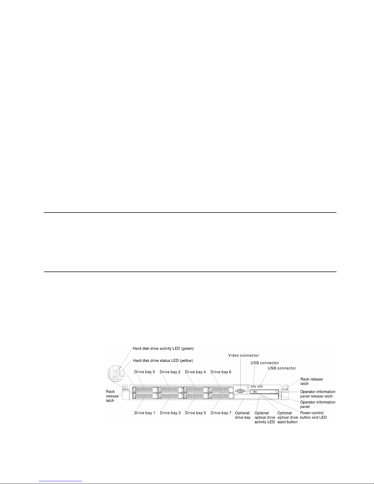
The hot-swap server models support up to eight 2.5-inch hot-swap SAS/SATA hard
disk drives or three 3.5-inch hot-swap SAS/SATA hard disk drives. The simple-swap
server models support up to three 3.5-inch simple-swap SATA hard disk drives. The
following illustration shows the 2.5-inch hot-swap server models with an optional
optical drive bay.
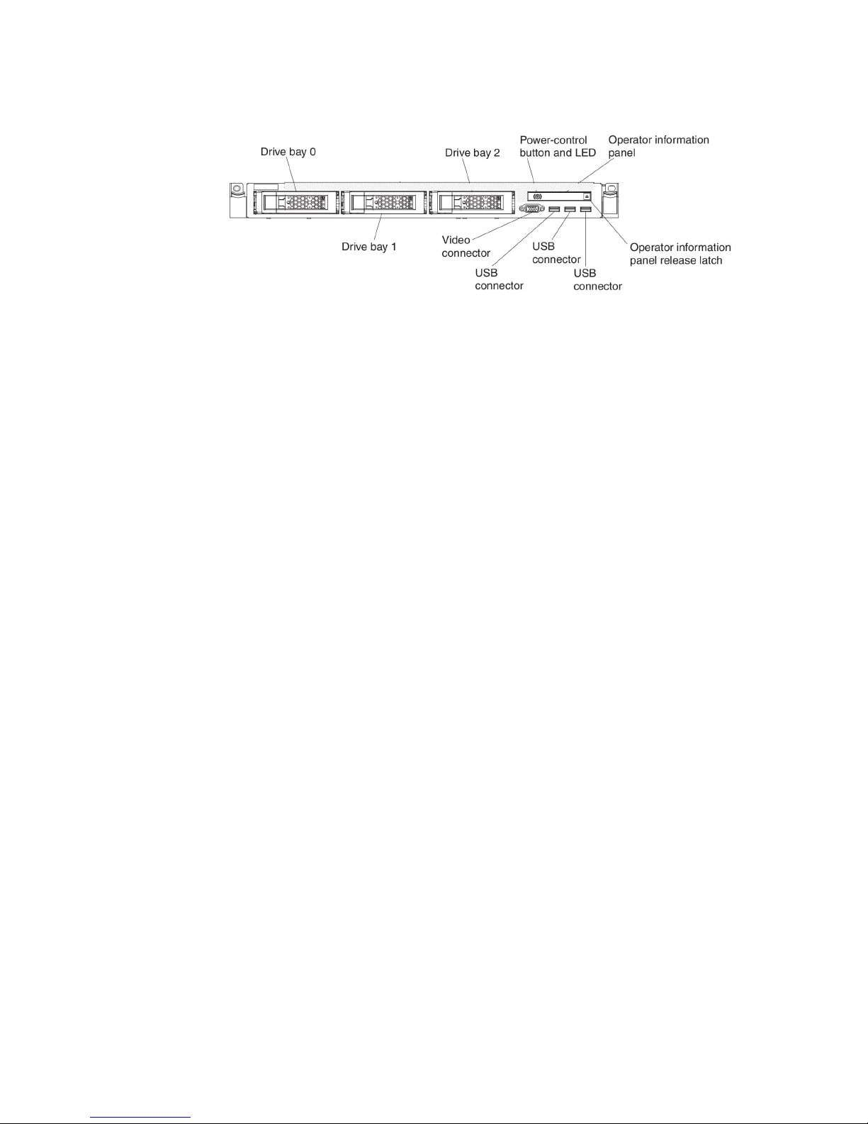
The following illustration shows the 3.5-inch hot-swap or simple-swap server
models. The servers support up to three 3.5-inch hot-swap SAS/SATA or
simple-swap SATA hard disk drives.
If firmware and documentation updates are available, you can download them from
the IBM website. The server might have features that are not described in the
documentation that comes with the server, and the documentation might be updated
occasionally to include information about those features, or technical updates might
be available to provide additional information that is not included in the server
documentation. To check for updates, go to http://www.ibm.com/supportportal/.
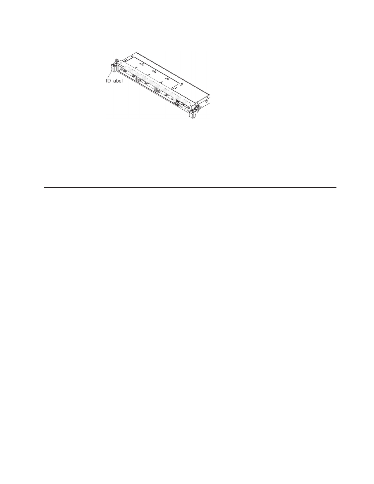
Record information about the server in the following table.
Product name IBM System x3550 M4 server
Machine type 7914
Model number _____________________________________________
Serial number _____________________________________________
The model number and serial number are on the ID label on the front of the server,
as shown in the following illustration.
2 IBM System x3550 M4 Type 7914: Installation and User’s Guide
Page 19
Note: The illustrations in this document might differ slightly from your hardware.
You can download an IBM ServerGuide Setup and Installation CD to help you
configure the hardware, install device drivers, and install the operating system.
For a list of supported optional devices for the server, see http://www.ibm.com/
servers/eserver/serverproven/compat/us/.
See the Rack Installation Instructions document on the IBM System x
Documentation CD for complete rack installation and removal instructions.
The IBM System x Documentation CD
The IBM System x Documentation CD contains documentation for the server in
Portable Document Format (PDF) and includes the IBM Documentation Browser to
help you find information quickly.
Hardware and software requirements
The IBM System x Documentation CD requires the following minimum hardware
and software:
v Microsoft Windows XP, Windows 2000, or Red Hat Linux
v 100 MHz microprocessor
v 32 MB of RAM
v Adobe Acrobat Reader 3.0 (or later) or xpdf, which comes with Linux operating
systems
Using the Documentation Browser
Use the Documentation Browser to browse the contents of the CD, read brief
descriptions of the documents, and view documents, using Adobe Acrobat Reader
or xpdf. The Documentation Browser automatically detects the regional settings in
use in your server and displays the documents in the language for that region (if
available). If a document is not available in the language for that region, the
English-language version is displayed.
Use one of the following procedures to start the Documentation Browser:
v If Autostart is enabled, insert the CD into the CD or DVD drive. The
Documentation Browser starts automatically.
v If Autostart is disabled or is not enabled for all users, use one of the following
procedures:
– If you are using a Windows operating system, insert the CD into the CD or
DVD drive and click Start -> Run.IntheOpen field, type
e:\win32.bat
where e is the drive letter of the CD or DVD drive, and click OK.
Chapter 1. The System x3550 M4 server 3
Page 20

– If you are using Red Hat Linux, insert the CD into the CD or DVD drive; then,
run the following command from the /mnt/cdrom directory:
sh runlinux.sh
Select the server from the Product menu. The Available Topics list displays all the
documents for the server. Some documents might be in folders. A plus sign (+)
indicates each folder or document that has additional documents under it. Click the
plus sign to display the additional documents.
When you select a document, a description of the document is displayed under
Topic Description. To select more than one document, press and hold the Ctrl key
while you select the documents. Click View Book to view the selected document or
documents in Acrobat Reader or xpdf. If you selected more than one document, all
the selected documents are opened in Acrobat Reader or xpdf.
To search all the documents, type a word or word string in the Search field and
click Search . The documents in which the word or word string appears are listed in
order of the most occurrences. Click a document to view it, and press Crtl+F to use
the Acrobat search function, or press Alt+F to use the xpdf search function within
the document.
Click Help for detailed information about using the Documentation Browser.
Related documentation
This Installation and User’s Guide contains general information about the server
including how to set up and cabling the server, how to install supported optional
devices, and how to configure the server. The following documentation also comes
with the server:
v Environmental Notices and User Guide
This document is in PDF on the IBM System x Documentation CD. It contains
translated environmental notices.
v IBM License Agreement for Machine Code
This document is in PDF. It provides translated versions of the IBM License
Agreement for Machine Code for your product.
v IBM Warranty Information
This printed document contains the warranty terms and a pointer to the IBM
Statement of Limited Warranty on the IBM website.
v Licenses and Attributions Documents
This document is in PDF. It provides the open-source notices.
v Problem Determination and Service Guide
This document is in PDF on the IBM System x Documentation CD. It contains
information to help you solve problems yourself, and it contains information for
service technicians.
v Rack Installation Instructions
This printed document contains instructions for installing the server in a rack and
comes with the rack kit.
v Safety Information
This document is in PDF on the IBM System x Documentation CD. It contains
translated caution and danger statements. Each caution and danger statement
that appears in the documentation has a number that you can use to locate the
corresponding statement in your language in the Safety Information document.
4 IBM System x3550 M4 Type 7914: Installation and User’s Guide
Page 21

Depending on the server model, additional documentation might be included on the
IBM System x Documentation CD.
The System x and BladeCenter Tools Center is an online information center that
contains information about tools for updating, managing, and deploying firmware,
device drivers, and operating systems. The System x and BladeCenter Tools Center
is at http://publib.boulder.ibm.com/infocenter/toolsctr/v1r0/index.jsp.
The server might have features that are not described in the documentation that
you received with the server. The documentation might be updated occasionally to
include information about those features, or technical updates might be available to
provide additional information that is not included in the server documentation.
These updates are available from the IBM website. To check for updates, go to
http://www.ibm.com/supportportal/.
Notices and statements in this document
The caution and danger statements in this document are also in the multilingual
Safety Information document, which is on the IBM System x Documentation CD.
Each statement is numbered for reference to the corresponding statement in your
language in the Safety Information document.
The following notices and statements are used in this document:
v Note: These notices provide important tips, guidance, or advice.
v Important: These notices provide information or advice that might help you avoid
inconvenient or problem situations.
v Attention: These notices indicate potential damage to programs, devices, or
data. An attention notice is placed just before the instruction or situation in which
damage might occur.
v Caution: These statements indicate situations that can be potentially hazardous
to you. A caution statement is placed just before the description of a potentially
hazardous procedure step or situation.
v Danger: These statements indicate situations that can be potentially lethal or
extremely hazardous to you. A danger statement is placed just before the
description of a potentially lethal or extremely hazardous procedure step or
situation.
Chapter 1. The System x3550 M4 server 5
Page 22

Features and specifications
The following information is a summary of the features and specifications of the
server. Depending on the model, some features might not be available, or some
specifications might not apply.
Table 1. Features and specifications
Microprocessor:
v Supports up to two Intel Xeon
series multi-core microprocessors (one
installed)
v Level-3 cache
v Two QuickPath Interconnect (QPI) links
speed up to 8.0 GT per second
Note:
v Use the Setup utility program to
determine the type and speed of the
microprocessors.
v For a list of supported microprocessors,
see http://www.ibm.com/servers/eserver/
serverproven/compat/us/.
Memory:
v Minimum: 2 GB
v Maximum: 768 GB
– 64 GB using unbuffered DIMMs
(UDIMMs)
– 384 GB using registered DIMMs
(RDIMMs)
– 768 GB using load reduction DIMMs
(LRDIMMs)
v Type:
– PC3-8500 (DDR3-1066), PC3-10600
(DDR3-1333), or PC3-12800
(DDR3-1600)
– Single-rank, dual-rank, or quad-rank
– Registered DIMM (RDIMM),
unbuffered DIMM (UDIMM), or load
reduced DIMM (LRDIMM)
v Slots: 24 dual inline
v Supports (depending on the model):
– 4 GB unbuffered DIMM
– 2 GB, 4 GB, 8 GB, and 16 GB
registered DIMMs
– 32 GB load reduction DIMM
SATA optical drives (optional for
2.5-inch models):
v DVD-ROM
v Multi-burner
Hot-swap fans:
v One microprocessor: 4 dual-motor
hot-swap fans.
v Two microprocessors: 6 dual-motor
hot-swap fans.
™
E5-2600
Hard disk drive expansion bays
(depending on the model):
v 2.5-inch models: Up to eight 2.5-inch
hot-swap SAS/SATA hard disk drive
bays (with an optional optical drive
bay)
v 3.5-inch models: Up to three 3.5-inch
hot-swap SAS/SATA or simple-swap
SATA hard disk drive bays
PCI expansion slots:
Supports two PCI riser slots:
v Slot 1 supports low-profile cards.
– PCI Express 3.0 x16
v Slot 2 supports half-length, full-height
cards.
– PCI Express 3.0 x8
– PCI Express 3.0 x16 (two
– PCI-X 64-bit/133 MHz
Video controller (integrated into
IMM2):
v Matrox G200eR2
Note: The maximum video resolution
is 1600 x 1200 at 75 Hz.
– SVGA compatible video controller
– DDR3 528 MHz SDRAM video
– Avocent Digital Video Compression
– 16 MB of video memory (not
Power supply:
v Up to two hot-swap power supplies for
redundancy support
– 550-watt ac
– 750-watt ac
– 750-watt dc
Note: Power supplies in the server must
be with the same power rating or
wattage.
microprocessors installed)
memory controller
expandable)
Environment: compliant with ASHRAE
class A3 specifications.
Server on:
v Temperature:
– 5°C to 40°C (41°F to 104°F)
– Altitude: 0 to 950 m (3,117 ft);
decrease the maximum system
temperature by 1°C for every 175-m
increase in altitude.
v Maximum altitude: 3,050 m (10,000 ft),
5°C to 28°C (41°F to 82°F)
v Humidity:
– Non-condensing: -12°C dew point
(10.4°F)
– Relative humidity: 8% to 85%
v Maximum dew point: 24°C (75°F)
v Maximum rate of temperature change:
– Tape drives: 5°C/hr (41°F/hr)
– Hard disk drives: 20°C/hr (68°F/hr)
Server off:
v Temperature: 5°C to 45°C (41°F to
113°F)
v Relative humidity: 8% to 85%
v Maximum dew point: 27°C (80.6°F)
Storage (non-operating):
v Temperature: 1°C to 60°C (33.8°F to
140.0°F)
v Maximum altitude: 3,050 m (10,000 ft)
v Relative humidity: 5% to 80%
v Maximum dew point: 29°C (84.2°F)
Shipment (non-operating):
v Temperature: -40°C to 60°C (-40°F to
140.0°F)
v Maximum altitude: 10,700 m (35,105 ft)
v Relative humidity: 5% to 100%
v Maximum dew point: 29°C (84.2°F)
Particulate contamination: airborne
particulates and reactive gases acting alone
or in combination with other environmental
factors such as humidity or temperature
might pose a risk to the server. For
information about the limits for particulates
and gases, see “Particulate contamination”
on page 129.
6 IBM System x3550 M4 Type 7914: Installation and User’s Guide
Page 23

Table 1. Features and specifications (continued)
Attention:
v Design to ASHRAE Class A3, ambient
of 40°C, with relaxed support:
– Support cloud like workload with no
performance degradation acceptable
(Turbo-Off)
– Under no circumstance, can any
combination of worst case workload
and configuration result in system
shutdown or design exposure at
40°C
v Specific microprocessors supported
environment:
– Microprocessor Intel Xeon E5-2690,
135W:
- Temperature: 10°C to 27°C
(41.0°F to 80.6°F)
- Altitude: 0 to 304.8 m (1,000 ft)
– Microprocessor models with 115W
and 130W:
- Temperature: 10°C to 35°C (50°F
to 95°F)
- Altitude: 0 to 914.4 m (3,000 ft)
Integrated functions:
v Integrated Management Module II
(IMM2), which consolidates multiple
management functions in a single chip.
v Intel I350AM4 Quad Port Gigabit
Ethernet controller with Wake on LAN
support
v Eight Universal Serial Bus (USB) ports
for 3.5-inch models. Seven Universal
Serial Bus (USB) ports for 2.5-inch
models. One port is for optional USB
flash device with embedded hypervisor
software is installed.
v Six network ports (four 1 Gb Ethernet
ports on the system board and two
additional ports when the optional IBM
Dual-Port 10 Gb Network Adapter is
installed)
v One System Management 1 Gb
Ethernet port on the rear connected to a
systems management network. This
system management connector is
dedicated to the IMM2 functions.
v One serial port
RAID controllers (depending on the
model):
v A ServeRAID H1110 SAS/SATA
adapter that provides RAID 0, 1, and
10.
v A ServeRAID M1115 SAS/SATA
adapter that provides RAID 0, 1, and
10 with optional FoD RAID 5/50 and
SED (Self Encrypting Drive) upgrade.
v A ServeRAID M5110 SAS/SATA
adapter that provides RAID 0, 1, and
10.
Optional upgrade:
– RAID 5/50 (512 MB Cache) with
optional FoD RAID 6/60 and SED
upgrade
– RAID 5/50 (512 MB Flash) with
optional FoD RAID 6/60 and SED
upgrade
– RAID 5/50 (1 GB Flash) with
optional FoD RAID 6/60 and SED
upgrade
– RAID 5/50 and SED (Zero Cache)
v A ServeRAID M5120 SAS/SATA
adapter that provides RAID 0, 1, and
10.
Optional upgrade:
– RAID 5/50 (512 MB Cache) with
optional FoD RAID 6/60 and SED
upgrade
– RAID 5/50 (512 MB Flash) with
optional FoD RAID 6/60 and SED
upgrade
– RAID 5/50 (1 GB Flash) with
optional FoD RAID 6/60 and SED
upgrade
– RAID 5/50 and SED (Zero Cache)
Size:
v 1U
v Height: 43 mm (1.7 inches)
v Depth: 734 mm (28.9 inches)
v Width: 429 mm (16.9 inches)
v Weight: approximately 16.4 kg (36.16
lb) when fully configured
Heat output:
Approximate heat output:
v Minimum configuration: 461 Btu per
hour (AC 135 watts)
v Maximum configuration: 2900 Btu per
hour (AC 850 watts)
Acoustical noise emissions:
v Sound power, idling: 6.2 bels maximum
v Sound power, operating: 6.5 bels
maximum
Electrical input:
v Sine-wave input (50 - 60 Hz) required
v Input voltage low range:
– Minimum: 100 V ac
– Maximum: 127 V ac
v Input voltage high range:
– Minimum: 200 V ac
– Maximum: 240 V ac
v Input kilovolt-amperes (kVA),
approximately:
– Minimum: 0.14 kVA
– Maximum: 0.90 kVA
Notes:
1. Power consumption and heat output
vary depending on the number and type
of optional features installed and the
power-management optional features in
use.
2. The noise emission level stated is the
declared (upper limit) sound power
level, in bels, for a random sample of
machines. All measurements are made
in accordance with ISO 7779 and
reported in conformance with ISO 9296.
Chapter 1. The System x3550 M4 server
7
Page 24

What your server offers
The server uses the following features and technologies:
v Features on Demand
If a Features on Demand feature is integrated in the server or in an optional
device that is installed in the server, you can purchase an activation key to
activate the feature. For information about Features on Demand, see
http://www.ibm.com/systems/x/fod/.
v Integrated Management Module II
The integrated management module II (IMM2) is the second generation of the
IMM. The IMM2 is the common management controller for IBM System x
hardware. The IMM2 consolidates multiple management functions in a single chip
on the server system board.
Some of the features that are unique to the IMM2 are enhanced performance,
expanded compatibility with blade servers, higher-resolution remote video,
expanded security options, and Feature on Demand enablement for hardware
and firmware options.
For additional information, see “Using the integrated management module II” on
page 115.
v UEFI-compliant server firmware
IBM System x Server Firmware (server firmware) offers several features,
including Unified Extensible Firmware Interface (UEFI) 2.1 compliance; Active
Energy Manager technology; enhanced reliability, availability, and serviceability
(RAS) capabilities; and basic input/output system (BIOS) compatibility support.
UEFI replaces the BIOS and defines a standard interface between the operating
system, platform firmware, and external devices. UEFI-compliant System x
servers are capable of booting UEFI-compliant operating systems, BIOS-based
operating systems, and BIOS-based adapters as well as UEFI-compliant
adapters.
Note: The server does not support DOS (Disk Operating System).
v IBM Dynamic System Analysis Preboot diagnostics programs
The Dynamic System Analysis (DSA) Preboot diagnostics programs are stored
on the integrated USB memory. It collects and analyzes system information to aid
in diagnosing server problems. The diagnostic programs collect the following
information about the server:
– System configuration
– Network interfaces and settings
– Installed hardware
– Light path diagnostics status
– Service processor status and configuration
– Vital product data, firmware, and UEFI (formerly BIOS) configuration
– Hard disk drive health
– RAID controller configuration
– Event logs for ServeRAID controllers and service processors
The diagnostic programs create a merged log that includes events from all
collected logs. The information is collected into a file that you can send to IBM
service and support. Additionally, you can view the information locally through a
generated text report file. You can also copy the log to a removable media and
view the log from a web browser.
8 IBM System x3550 M4 Type 7914: Installation and User’s Guide
Page 25

For additional information about DSA Preboot diagnostics, see the Problem
Determination and Service Guide on the IBM System x Documentation CD
v Multi-core processing
™
The server supports up to two Intel Xeon
E5-2600 series multi-core
microprocessors. The server comes with only one microprocessor installed.
v IBM Systems Director
IBM Systems Director is a workgroup-hardware-management tool that you can
use to centrally manage System x and xSeries servers. For more information,
see the IBM Systems Director Information Center at http://
publib.boulder.ibm.com/infocenter/director/v6r1x/index.jsp?topic=/director_6.1/
fqm0_main.html and “IBM Systems Director” on page 12.
v IBM X-Architecture technology
IBM X-Architecture technology combines proven, innovative IBM designs to make
your Intel-processor-based server powerful, scalable, and reliable. For more
information, see http://www.ibm.com/servers/eserver/xseries/xarchitecture/
enterprise/index.html.
™
– Active
Memory
The Active Memory feature improves the reliability of memory through memory
mirrored channel mode. Memory mirrored channel mode replicates and stores
data on two pairs of DIMMs within two channels simultaneously. If a failure
occurs, the memory controller switches from the primary pair of memory
DIMMs to the backup pair of DIMMs. For more information about installing
DIMMs for memory mirrored channel mode, see “Installing a memory module”
on page 59.
– Large system-memory capacity
The memory bus supports up to 384 GB of system memory when registered
DIMMs are installed. The server supports up to 64 GB if unbuffered DIMMs
are installed. The memory controller supports error correcting code (ECC) for
up to 24 industry-standard PC3-8500 (DDR3-1066), PC3-10600 (DDR3-1333),
or PC3-12800 (DDR3-1600), DDR3 (third-generation double-data-rate),
synchronous dynamic random access memory (SDRAM) dual inline memory
modules (DIMMs).
v IBM ServerGuide Setup and Installation CD
The ServerGuide Setup and Installation CD, which you can download from the
web, provides programs to help you set up the server and install a Windows
operating system. The ServerGuide program detects installed optional hardware
devices and provides the correct configuration programs and device drivers. For
more information about the ServerGuide Setup and Installation CD, see “Using
the ServerGuide Setup and Installation CD” on page 106.
Chapter 1. The System x3550 M4 server 9
Page 26

v Integrated network support
The server comes with an integrated dual-port Intel Gigabit Ethernet controller,
which supports connection to a 10 Mbps, 100 Mbps, or 1000 Mbps network. For
more information, see “Configuring the Ethernet controller” on page 119.
v Integrated Trusted Platform Module (TPM)
This integrated security chip performs cryptographic functions and stores private
and public secure keys. It provides the hardware support for the Trusted
Computing Group (TCG) specification. You can download the software to support
the TCG specification, when the software is available. See http://www.ibm.com/
servers/eserver/xseries/scalable_family.html for details about the TPM
implementation. You can enable TPM support through the Setup utility under the
System Security menu option.
v Large data-storage capacity and hot-swap capability
The hot-swap server models support a maximum of eight 2.5-inch or three
3.5-inch hot-swap Serial Attached SCSI (SAS) hard disk drives or hot-swap
Serial ATA (SATA) hard disk drives. The simple-swap server models support a
maximum of three 3.5-inch simple-swap SATA hard disk drives.
With the hot-swap feature, you can add, remove, or replace hard disk drives
without turning off the server.
v Light path diagnostics
Light path diagnostics provides LEDs to help you diagnose problems. For more
information about the light path diagnostics, see “Light path diagnostics panel” on
page 15 and the Problem Determination and Service Guide on the IBM System x
Documentation CD.
v PCI adapter capabilities
The server has two PCI interface slots (one supports low-profile cards, and one
supports half-length, full-height cards). Slot 2 can support PCI Express or PCI-X
adapters through an optional PCI riser card. See “Installing an adapter” on page
67 for detailed information.
v Active Energy Manager
The IBM Active Energy Manager solution is an IBM Systems Director plug-in that
measures and reports server power consumption as it occurs. This enables you
to monitor power consumption in correlation to specific software application
programs and hardware configurations. You can obtain the measurement values
through the systems-management interface and view them, using IBM Systems
Director. For more information, including the required levels of IBM Systems
Director and Active Energy Manager, see the IBM Systems Director Information
Center at http://publib.boulder.ibm.com/infocenter/director/v6r1x/index.jsp?topic=/
director_6.1/fqm0_main.html, or see http://www.ibm.com/servers/systems/
management/director/resources/.
v Redundant connection
The addition of the optional Ethernet daughter card provides failover capability to
a redundant Ethernet connection with the applicable application installed. If a
problem occurs with the primary Ethernet connection and the optional Ethernet
daughter card is installed on the server, all Ethernet traffic that is associated with
the primary connection is automatically switched to the optional redundant
Ethernet daughter card connection. If the applicable device drivers are installed,
this switching occurs without data loss and without user intervention.
v Redundant cooling and optional power capabilities
The server supports a maximum of two 550-watt or 750-watt hot-swap power
supplies and six dual-motor hot-swap fans, which provide redundancy and
hot-swap capability for a typical configuration. The redundant cooling by the fans
10 IBM System x3550 M4 Type 7914: Installation and User’s Guide
Page 27

in the server enables continued operation if one of the fans fails. The server
comes with one 550-watt or 750-watt hot-swap power supply and four fans.
You must install the fourth and sixth fans when you install the second
microprocessor in the server. You can order the second optional power supply for
power redundancy.
Note: You cannot mix 550-watt and 750-watt power supplies in the server.
v ServeRAID support
The ServeRAID adapter provides hardware redundant array of independent disks
(RAID) support to create configurations. The standard RAID adapter provides
RAID levels 0, 1, and 10. An optional RAID adapter is available for purchase.
v Systems-management capabilities
The server comes with an integrated management module II (IMM2). When the
IMM2 is used with the systems-management software that comes with the server,
you can manage the functions of the server locally and remotely. The IMM2 also
provides system monitoring, event recording, and network alert capability. The
system-management connector on the rear of the server is dedicated to the
IMM2. The dedicated system-management connector provides additional security
by physically separating the management network traffic from the production
network. You can use the Setup utility to configure the server to use a dedicated
systems-management network or a shared network.
Reliability, availability, and serviceability
Three important computer design features are reliability, availability, and
serviceability (RAS). The RAS features help to ensure the integrity of the data that
is stored in the server, the availability of the server when you need it, and the ease
with which you can diagnose and correct problems.
Your server has the following RAS features:
v 3-year parts and 3-year labor limited warranty for machine type 7914
v Automatic error retry and recovery
v Automatic restart on nonmaskable interrupt (NMI)
v Automatic restart after a power failure
v Backup basic input/output system switching under the control of the Integrated
Management Module II (IMM2)
v Built-in monitoring for fan, power, temperature, voltage, and power-supply
redundancy
v Cable-presence detection on most connectors
v Chipkill memory protection
v Diagnostic support for ServeRAID and Ethernet adapters
v Error codes and messages
v Error correcting code (ECC) L2 cache and system memory
v Hot-swap cooling fans with speed-sensing capability
v Hot-swap hard disk drives
v Information and light path diagnostics LED panels
v Integrated Management Module II (IMM2)
v Menu-driven setup, system configuration, and redundant array of independent
disks (RAID) configuration programs
v Microprocessor built-in self-test (BIST), internal error signal monitoring,
configuration checking, and microprocessor and voltage regulator module failure
identification through light path diagnostics
v Memory mirrored channel support (memory mirrored channel are mutually
exclusive of each other)
Chapter 1. The System x3550 M4 server 11
Page 28

v Parity checking on the small computer system interface (SCSI) bus and PCI
buses
v Power management: Compliance with Advanced Configuration and Power
Interface (ACPI)
v Power-on self-test (POST)
v Predictive Failure Analysis (PFA) alerts on memory, SAS/SATA hard disk drives,
fans, and power supplies
v Redundant Ethernet capabilities with failover support
v Redundant hot-swap power supplies and redundant hot-swap fans
v Redundant Network Interface Card (NIC) support
v Remind button to temporarily turn off the system-error LED
v Remote system problem-determination support
v ROM-based diagnostics
v ROM checksums
v Serial Presence Detection (SPD) on memory, VPD, power supply, and hard disk
drives backplane
v Single-DIMM isolation of excessive correctable error or multi-bit error by the
Unified Extensible Firmware Interface (UEFI)
v Standby voltage for system-management features and monitoring
v Startup (boot) from LAN through remote initial program load (RIPL) or dynamic
host configuration protocol/boot protocol (DHCP/BOOTP)
v System auto-configuring from the configuration menu
v System-error logging (POST and IMM2)
v Systems-management monitoring through the Inter-Integrated Circuit (IC)
protocol bus
v Upgradeable POST, Unified Extensible Firmware Interface (UEFI), diagnostics,
IMM2 firmware, and read-only memory (ROM) resident code, locally or over the
LAN
v Vital product data (VPD) on microprocessors, system board, power supplies, and
SAS/SATA (hot-swap hard disk drive) backplane
v Wake on LAN capability
IBM Systems Director
IBM Systems Director is a platform-management foundation that streamlines the
way you manage physical and virtual systems supports multiple operating systems
and virtualization technologies in IBM and non-IBM x86 platforms.
Through a single user interface, IBM Systems Director provides consistent views for
viewing managed systems, determining how these systems relate to one other, and
identifying their statuses, helping to correlate technical resources with business
needs. A set of common tasks that are included with IBM Systems Director provides
many of the core capabilities that are required for basic management, which means
instant out-of-the-box business value. The common tasks include the following:
v Discovery
v Inventory
v Configuration
v System health
v Monitoring
v Updates
v Event notification
v Automation for managed systems
12 IBM System x3550 M4 Type 7914: Installation and User’s Guide
Page 29
The IBM Systems Director web and command-line interfaces provide a consistent
interface that is focused on driving these common tasks and capabilities:
v Discovering, navigating, and visualizing systems on the network with the detailed
inventory and relationships to the other network resources
v Notifying users of problems that occur on systems and the ability to isolate the
sources of the problems
v Notifying users when systems need updates and distributing and installing
updates on a schedule
v Analyzing real-time data for systems and setting critical thresholds that notify the
administrator of emerging problems
v Configuring settings of a single system and creating a configuration plan that can
apply those settings to multiple systems
v Updating installed plug-ins to add new features and functions to the base
capabilities
v Managing the life cycles of virtual resources
For more information about IBM Systems Director, see the IBM Systems Director
Information Center at http://publib.boulder.ibm.com/infocenter/director/v6r1x/
index.jsp?topic=/director_6.1/fqm0_main.html and the Systems Management web
page at http://www.ibm.com/systems/management/, which presents an overview of
IBM Systems Management and IBM Systems Director.
The UpdateXpress System Packs
The Update Xpress System Pack Installer detects supported and installed device
drivers and firmware in the server and installs available updates. For additional
information and to download the UpdateXpress System Pack Installer, go to the
ToolsCenter for System x and BladeCenter at, go to http://www.ibm.com/systems/
support/supportsite.wss/docdisplay?lndocid=SERV-XPRESS&brandind=5000008.
Server controls, LEDs, and power
This section describes the controls and light-emitting diodes (LEDs) and how to turn
the server on and off. For the locations of other LEDs on the system board, see
“System-board LEDs” on page 37.
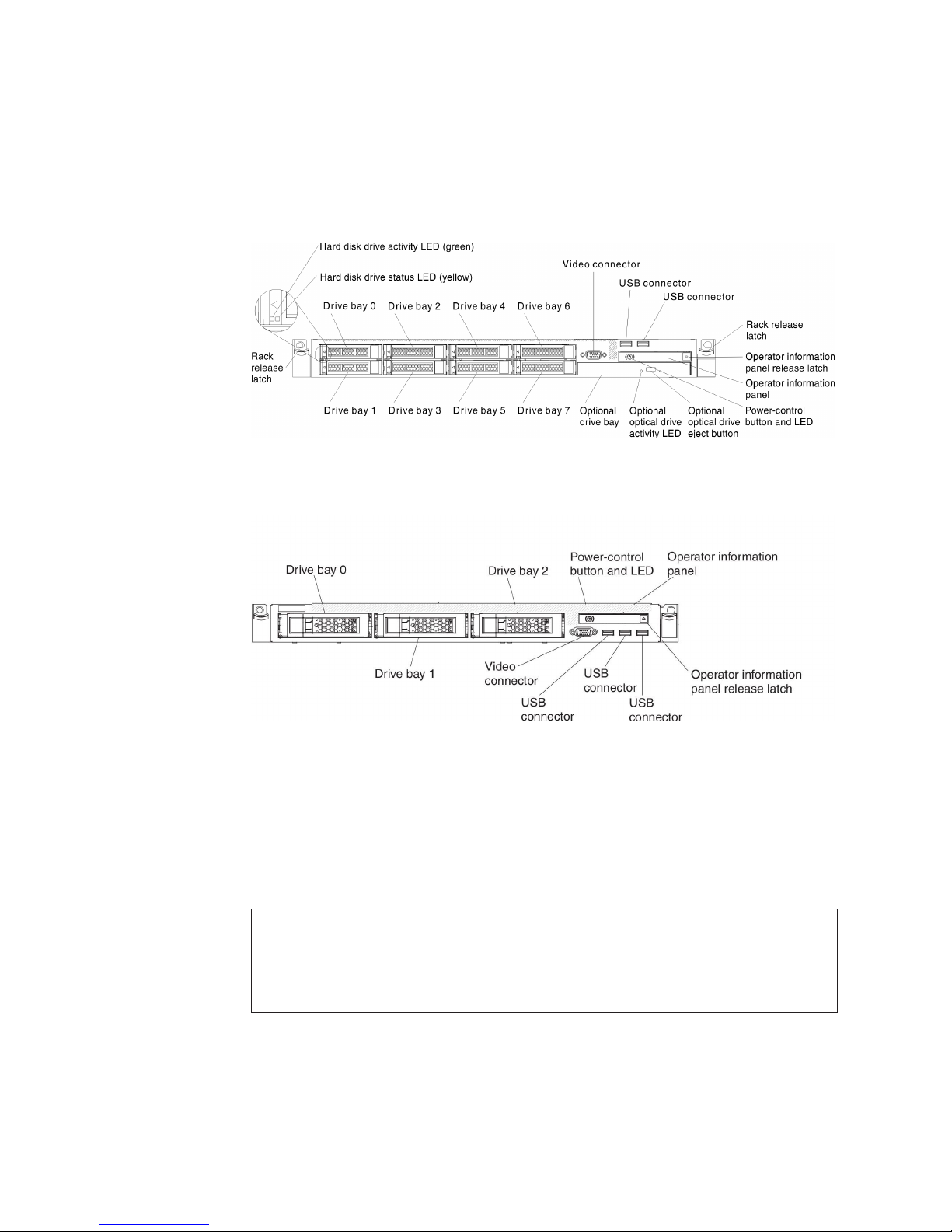
Front view
The following illustration shows the controls, LEDs, and connectors on the front of
the 2.5-inch hard disk drive server model.
The following illustration shows the controls, LEDs, and connectors on the front of
the 3.5-inch hard disk drive server model.
Chapter 1. The System x3550 M4 server 13
Page 30
v Rack release latches: Press the latches on each front side of the server to
remove the server from the rack.
v Hard disk drive activity LEDs: This LED is used on hot-swap SAS or SATA
hard disk drives. Each hot-swap hard disk drive has an activity LED, and when
this LED is flashing, it indicates that the drive is in use.
v Hard disk drive status LEDs: This LED is used on hot-swap SAS or SATA hard
disk drives. When this LED is lit, it indicates that the drive has failed. If an
optional IBM ServeRAID controller is installed in the server, when this LED is
flashing slowly (one flash per second), it indicates that the drive is being rebuilt.
When the LED is flashing rapidly (three flashes per second), it indicates that the
controller is identifying the drive.
v Optional DVD eject button: Press this button to release a DVD or CD from the
optional DVD drive.
v Optional DVD drive activity LED: When this LED is lit, it indicates that the
optional DVD drive is in use.
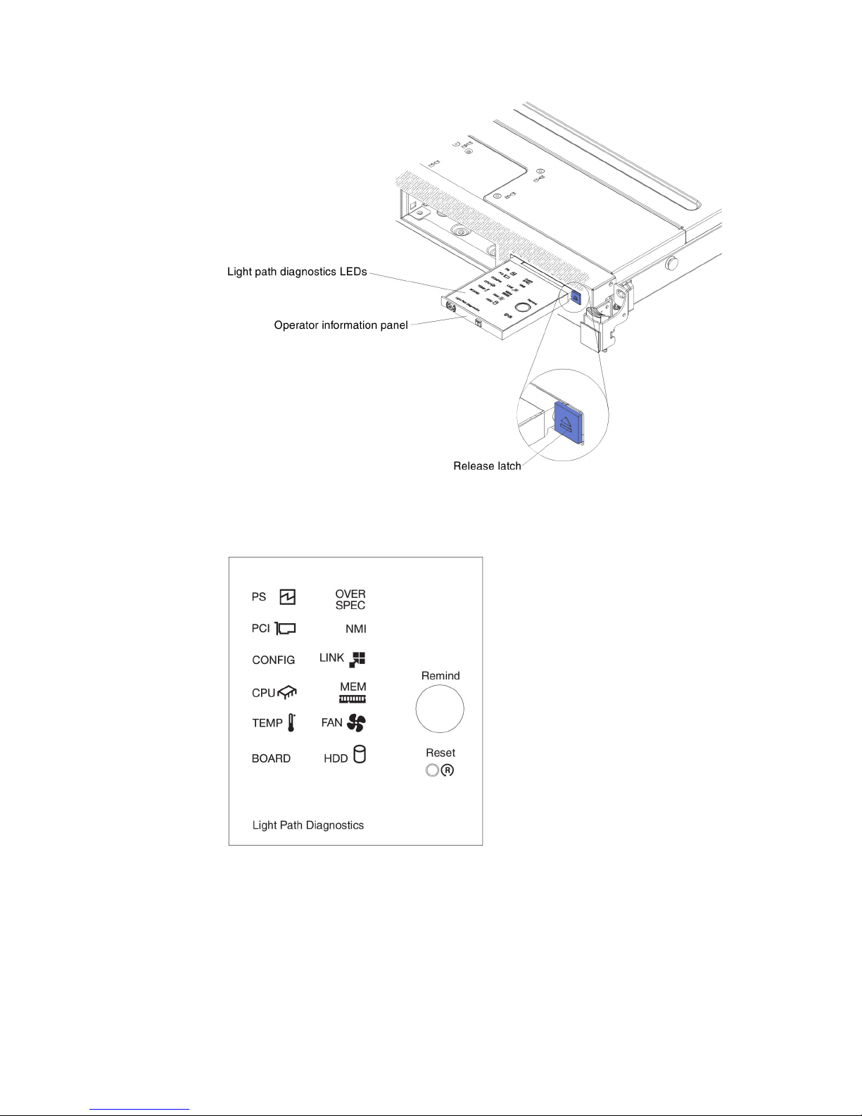
v Operator information panel: This panel contains controls and LEDs that provide
information about the status of the server. For information about the controls and
LEDs on the operator information panel, see “Operator information panel.”
v Operator information panel release latch: Press the blue release latch to pull
out the light path diagnostics panel and view the light path diagnostics LEDs and
buttons. See “Light path diagnostics panel” on page 15 and the Problem
Determination and Service Guide for more information about the light path
diagnostics.
v Video connector: Connect a monitor to this connector. The video connectors on
the front and rear of the server can be used simultaneously.
Note: The maximum video resolution is 1600 x 1200 at 75 Hz.
v USB connectors: Connect a USB device, such as a USB mouse or keyboard to
any of these connectors.
Operator information panel
The following illustration shows the controls and LEDs on the operator information
panel.
14 IBM System x3550 M4 Type 7914: Installation and User’s Guide
Page 31
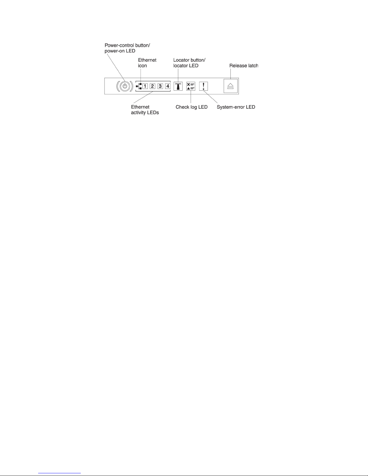
v Power-control button and power-on LED: Press this button to turn the server
on and off manually. The states of the power-on LED are as follows:
Off: Power is not present or the power supply, or the LED itself has failed.
Flashing rapidly (4 times per second): The server is turned off and is not
ready to be turned on. The power-control button is disabled. This will last
approximately 5 to 10 seconds.
Flashing slowly (once per second): The server is turned off and is ready to
be turned on. You can press the power-control button to turn on the server.
Lit: The server is turned on.
v Ethernet activity LEDs: When any of these LEDs is lit, they indicate that the
server is transmitting to or receiving signals from the Ethernet LAN that is
connected to the Ethernet port that corresponds to that LED.
v System-locator button/LED: Use this blue LED to visually locate the server
among other servers. A system-locator LED is also on the rear of the server. This
LED is used as a presence detection button as well. You can use IBM Systems
Director or IMM2 web interface to light this LED remotely. This LED is controlled
by the IMM2. The locator button is pressed to visually locate the server among
the others servers.
v Check log LED: When this yellow LED is lit, it indicates that a system error has
occurred. Check the error log for additional information. See the Problem
Determination and Service Guide on the System x Documentation CD for more
information about error logs.
v System-error LED: When this yellow LED is lit, it indicates that a system error
has occurred. A system-error LED is also on the rear of the server. An LED on
the light path diagnostics panel on the operator information panel or on the
system board is also lit to help isolate the error. This LED is controlled by the
IMM2.
Light path diagnostics panel
The light path diagnostics panel is located on the top of the operator information
panel. For additional information about the LEDs on the light path diagnostics panel,
see “Light path diagnostics LEDs” on page 17.
Note: The system service label inside the server cover also provides information
about the location of the light path diagnostics LEDs.
To access the light path diagnostics panel, press the blue release latch on the
operator information panel. Pull forward on the panel until the hinge of the operator
information panel is free of the server chassis. Then pull down on the panel, so that
you can view the light path diagnostics panel information.
Chapter 1. The System x3550 M4 server 15
Page 32
The following illustration shows the LEDs and controls on the light path diagnostics
panel.
v Remind button: This button places the system-error LED/check log LED on the
front panel into Remind mode. In Remind mode, the system-error LED flashes
once every 2 seconds until the problem is corrected, the server is restarted, or a
new problem occurs.
By placing the system-error LED indicator in Remind mode, you acknowledge
that you are aware of the last failure but will not take immediate action to correct
the problem. The remind function is controlled by the IMM2.
16 IBM System x3550 M4 Type 7914: Installation and User’s Guide
Page 33

v Reset button: Press this button to reset the server and run the power-on
self-test (POST). You might have to use a pen or the end of a straightened paper
clip to press the button. The Reset button is in the lower-right corner of the light
path diagnostics panel.
Light path diagnostics LEDs: The following table describes the LEDs on the light
path diagnostics panel and suggested actions to correct the detected problems.
Table 2. Light path diagnostics panel LEDs
v Follow the suggested actions in the order in which they are listed in the Action column until the problem
is solved.
v If an action step is preceded by "(trained technician only)," that step must be performed only by a trained
technician.
LED Description Action
Check log LED An error has occurred and cannot
be isolated without performing
certain procedures.
System-error
LED
PS When only the PS LED is lit, a
OVER SPEC The system consumption reaches
An error has occurred.
power supply has failed.
PS + CONFIG
When both the PS and CONFIG
LEDs are lit, the power supply
configuration is invalid.
the power supply over-current
protection point or the power
supplies are damaged.
1. Check the IMM2 system event log and the system-error
log for information about the error.
2. Save the log if necessary and clear the log afterwards.
1. Check the light path diagnostics LEDs and follow the
instructions.
2. Check the IMM2 system event log and the system-error
log for information about the error.
3. Save the log if necessary and clear the log afterwards.
If the CONFIG LED is not lit, the system might detect a power
supply error. Complete the following steps to correct the
problem:
1. Check the power-supply with a lit yellow LED (see “AC
power-supply LEDs” on page 23).
2. Make sure that the power supplies are seated correctly
and plugged in a good AC outlet.
3. Remove one of the power supplies to isolate the failed
power supply.
4. Make sure that both power supplies installed in the server
are of the same AC input voltage.
5. Replace the failed power supply (see “Installing a
hot-swap ac power supply” on page 86).
If the PS LED and the CONFIG LED are lit, the system issues
an invalid power configuration error. Make sure that both
power supplies installed in the server are of the same rating
or wattage.
1. If the Pwr Rail (1, 2, 3, 4, 5, or 6) error was not detected,
complete the following steps:
a. Use the IBM Power Configurator utility to determine
current system power consumption. For more
information and to download the utility, go to
http://www-03.ibm.com/systems/bladecenter/resources/
powerconfig.html.
b. Replace the failed power supply (see “Installing a
hot-swap ac power supply” on page 86).
2. If the Pwr Rail (1, 2, 3, 4, 5, or 6) error was also detected,
follow actions in the "Power problems" under the
Troubleshooting tables and "Solving power problems" in
the Problem Determination and Service Guide.
Chapter 1. The System x3550 M4 server 17
Page 34
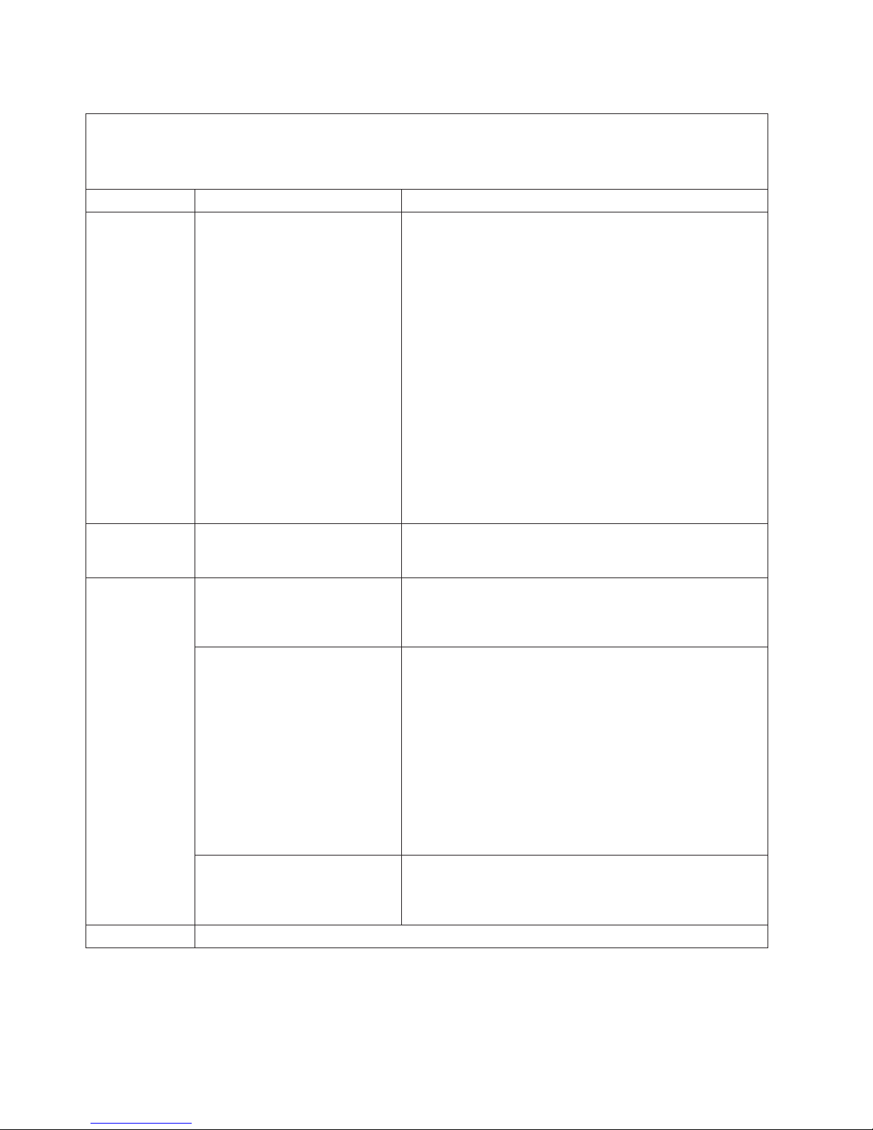
Table 2. Light path diagnostics panel LEDs (continued)
v Follow the suggested actions in the order in which they are listed in the Action column until the problem
is solved.
v If an action step is preceded by "(trained technician only)," that step must be performed only by a trained
technician.
LED Description Action
PCI An error has occurred on a PCI
card, a PCI bus, or on the system
board. An additional LED is lit
next to a failing PCI slot.
NMI A nonmaskable interrupt has
occurred, or the NMI button was
pressed.
CONFIG CONFIG + PS
An invalid power configuration
error has occurred.
CONFIG + CPU
A hardware configuration error
has occurred.
CONFIG + MEM
A hardware configuration error
has occurred.
LINK Reserved.
1. Check the riser-card LEDs, the ServeRAID error LED, and
the optional network adapter error LED to identify the
component that caused the error.
2. Check the system-error log for information about the error.
3. If you cannot isolate the failing component by using the
LEDs and the information in the system-error log, remove
one component at a time; and restart the server after each
component is removed.
4. Replace the following components, in the order shown,
restarting the server each time:
v PCI riser cards
v ServeRAID adapter
v Optional network adapter
v (Trained technician only) System board
5. If the failure remains, go to http://www.ibm.com/systems/
support/supportsite.wss/docdisplay?brandind=5000008
&lndocid=SERV-CALL.
1. Check the system-error log for information about the error.
2. Restart the server.
If the CONFIG LED and the PS LED are lit, the system issues
an invalid power configuration error. Make sure that both
power supplies installed in the server are of the same rating
or wattage.
If the CONFIG LED and the CPU LED are lit, complete the
following steps to correct the problem:
1. Check the microprocessors that were just installed to
make sure that they are compatible with each other (see
“Installing a second microprocessor and heat sink” on
page 79 for additional information about microprocessor
requirements).
2. (Trained technician only) Replace the incompatible
microprocessor.
3. Check the system-error logs for information about the
error. Replace any component that is identified in the error
log.
If the CONFIG LED and the MEM LED are lit, check the
system-event log in the Setup utility or IMM2 error messages
(see the Problem Determination and Service Guide for more
information).
18 IBM System x3550 M4 Type 7914: Installation and User’s Guide
Page 35

Table 2. Light path diagnostics panel LEDs (continued)
v Follow the suggested actions in the order in which they are listed in the Action column until the problem
is solved.
v If an action step is preceded by "(trained technician only)," that step must be performed only by a trained
technician.
LED Description Action
CPU When only the CPU LED is lit, a
microprocessor has failed.
If the CONFIG LED is not lit, a microprocessor failure occurs,
complete the following steps:
1. (Trained technician only) Make sure that the failing
microprocessor and its heat sink, which are indicated by a
lit LED on the system board, are installed correctly. See
“Installing a second microprocessor and heat sink” on
page 79 for information about installation and
requirements.
2. (Trained technician only) Replace the failing
microprocessor (see “Installing a second microprocessor
and heat sink” on page 79).
3. If the failure remains, go to http://www.ibm.com/systems/
support/supportsite.wss/docdisplay?brandind=5000008
&lndocid=SERV-CALL.
CPU + CONFIG
When both the CPU LED and the
CONFIG LED are lit, the
microprocessor configuration is
invalid.
If the CONFIG LED and the CPU LED are lit, the system
issues an invalid microprocessor configuration error. Complete
the following steps to correct the problem:
1. Check the microprocessors that were just installed to
make sure that they are compatible with each other (see
“Installing a second microprocessor and heat sink” on
page 79 for additional information about microprocessor
requirements) and use the Setup utility and select System
Information → System Summary → Processor Details to
verify the microprocessors information.
2. (Trained technician only) Replace the incompatible
microprocessor.
3. Check the system-error logs for information about the
error. Replace any component that is identified in the error
log.
MEM When only the MEM LED is lit, a
memory error has occurred.
Note: Each time you install or remove a DIMM, you must
disconnect the server from the power source; then, wait 10
seconds before restarting the server.
MEM + CONFIG
When both the MEM and CONFIG
LEDs are lit, the memory
configuration is invalid.
If the CONFIG LED is not lit, the system might detect a
memory error. Complete the following steps to correct the
problem:
1. Update the server firmware to the latest level (see the
Problem Determination and Service Guide for more
information).
2. Reseat or swap the DIMMs with lit LED.
3. Check the system-event log in the Setup utility or IMM
error messages (see the Problem Determination and
Service Guide for more information).
4. Replace the failing DIMM (see “Installing a memory
module” on page 59).
If the MEM LED and the CONFIG LED are lit, check the
system-event log in the Setup utility or IMM2 error messages
(see the Problem Determination and Service Guide for more
information).
Chapter 1. The System x3550 M4 server 19
Page 36

Table 2. Light path diagnostics panel LEDs (continued)
v Follow the suggested actions in the order in which they are listed in the Action column until the problem
is solved.
v If an action step is preceded by "(trained technician only)," that step must be performed only by a trained
technician.
LED Description Action
TEMP The system temperature has
exceeded a threshold level. A
failing fan can cause the TEMP
LED to be lit.
FAN A fan has failed, is operating too
slowly, or has been removed. The
TEMP LED might also be lit.
BOARD An error has occurred on the
system board.
HDD A hard disk drive has failed or is
missing.
1. Make sure that the heat sink is seated correctly.
2. Determine whether a fan has failed. If it has, replace it.
3. Make sure that the room temperature is not too high. See
“Features and specifications” on page 6 for the server
temperature information.
4. Make sure that the air vents are not blocked.
5. Make sure that the heat sink, the fan on the adapter, or
the optional network adapter is seated correctly. If the fan
has failed, replace it.
6. If the failure remains, go to http://www.ibm.com/systems/
support/supportsite.wss/docdisplay?brandind=5000008
&lndocid=SERV-CALL.
1. Reseat the failing fan, which is indicated by a lit LED near
the fan connector on the system board.
2. Replace the failing fan (see “Installing a hot-swap fan
assembly” on page 93).
1. Check the LEDs on the system board to identify the
component that caused the error. The BOARD LED can
be lit due to any of the following reasons:
v Battery
v (Trained technician only) System board
2. Check the system-error log for information about the error.
3. Replace the failing component:
v Battery
v (Trained technician only) System board
1. Check the LEDs on the hard disk drives for the drive with
a lit status LED and reseat the hard disk drive.
2. Reseat the hard disk drive backplane.
3. For more information, see the “Hard disk drive problems”
under the Troubleshooting tables in the Problem
Determination and Service Guide.
4. If the error remains, replace the following components one
at a time, in the order listed, restarting the server after
each:
a. Replace the hard disk drive.
b. Replace the hard disk drive backplane.
5. If the problem remains, go to http://www.ibm.com/systems/
support/supportsite.wss/docdisplay?brandind=5000008
&lndocid=SERV-CALL.
20 IBM System x3550 M4 Type 7914: Installation and User’s Guide
Page 37

Rear view
The following illustration shows the connectors on the rear of the server.
v NMI button: Press this button to force a nonmaskable interrupt to the
microprocessor. It allows you to blue screen the server and take a memory dump
(use this button only when directed by the IBM service support). You might have
to use a pen or the end of a straightened paper clip to press the button. The NMI
button is in the lower left-hand corner on the rear of the server.
v PCI slot 1: Insert a low-profile PCI Express adapter into this slot.
v PCI slot 2: Insert a half-length, full-height PCI Express or PCI-X adapter into this
slot.
v Power connector: Connect the power cord to this connector.
Note: Power supply 1 is the default/primary power supply. If power supply 1
fails, you must replace it immediately.
v Video connector: Connect a monitor to this connector. The video connectors on
the front and rear of the server can be used simultaneously.
Note: The maximum video resolution is 1600 x 1200 at 75 Hz.
v Serial connector: Connect a 9-pin serial device to this connector. The serial port
is shared with the integrated management module II (IMM2). The IMM2 can take
control of the shared serial port to redirect serial traffic, using Serial over LAN
(SOL).
v USB connectors: Connect a USB device, such as a USB mouse or keyboard to
any of these connectors.
v Systems-management Ethernet connector: Use this connector to connect the
server to a network for full systems-management information control. This
connector is used only by the integrated management module (IMM2). A
dedicated management network provides additional security by physically
separating the management network traffic from the production network. You can
use the Setup utility to configure the server to use a dedicated systems
management network or a shared network. See Using the Setup utility in the
Problem Determination and Service Guide for more information.
v Ethernet connectors: Use either of these connectors to connect the server to a
network. When you enable shared Ethernet for IMM2 in the Setup utility, you can
access the IMM2 using either the Ethernet 1 or the system-management
Ethernet (default) connector. See Using the Setup utility in the Problem
Determination and Service Guide for more information.
The following illustration shows the LEDs on the rear of the server.
Chapter 1. The System x3550 M4 server 21
Page 38

The following illustration shows the LEDs on a dc power supply.
v Ethernet activity LEDs: When these LEDs are lit, they indicate that the server is
transmitting to or receiving signals from the Ethernet LAN that is connected to
the Ethernet port.
v Ethernet link LEDs: When these LEDs are lit, they indicate that there is an
active link connection on the 10BASE-T, 100BASE-TX, or 1000BASE-TX
interface for the Ethernet port.
v AC power LED: Each hot-swap ac power supply has an ac power LED. When
the ac power LED is lit, it indicates that sufficient power is coming into the power
supply through the power cord. During typical operation, the ac power LED is lit.
For any other combination of LEDs, see the Problem Determination and Service
Guide on the IBM System x Documentation CD.
v DC power LED: Each hot-swap ac power supply has a dc power LED. When the
dc power LED is lit, it indicates that the power supply is supplying adequate dc
power to the system. During typical operation, both the ac and dc power LEDs
are lit. For any other combination of LEDs, see the Problem Determination and
Service Guide on the IBM System x Documentation CD.
v IN OK power LED: Each hot-swap dc power supply has an IN OK power LED.
When the IN OK power LED is lit, it indicates that sufficient power is coming into
the power supply through the power cord. During typical operation, both the IN
OK and OUT OK power LEDs are lit. For any other combination of LEDs, see the
Problem Determination and Service Guide on the IBM System x Documentation
CD.
v OUT OK power LED: Each hot-swap dc power supply has an OUT OK power
LED. When the OUT OK power LED is lit, it indicates that the power supply is
supplying adequate dc power to the system. During typical operation, both the IN
OK and OUT OK power LEDs are lit. For any other combination of LEDs, see the
Problem Determination and Service Guide on the IBM System x Documentation
CD.
22 IBM System x3550 M4 Type 7914: Installation and User’s Guide
Page 39
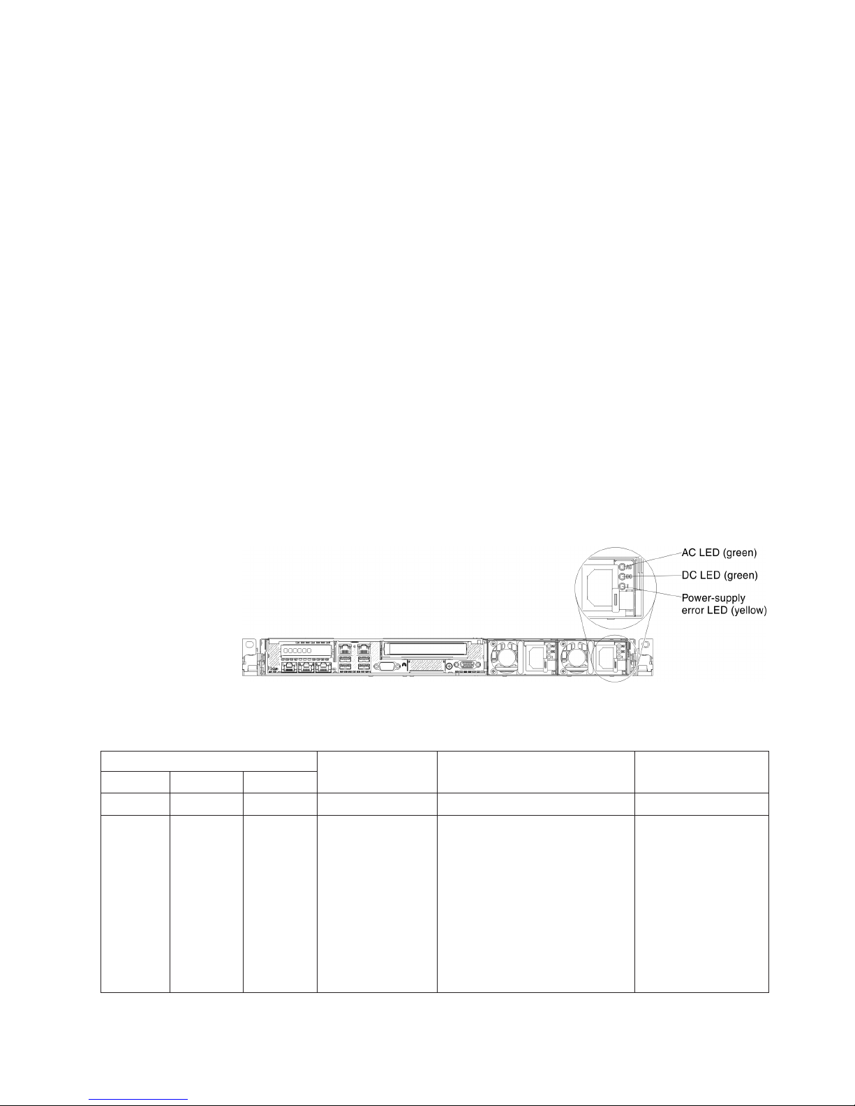
v Power-supply error LED: When the power-supply error LED is lit, it indicates
that the power supply has failed.
Note: Power supply 1 is the default/primary power supply. If power supply 1
fails, you must replace the power supply immediately.
v Power-on LED: When this LED is lit and not flashing, it indicates that the server
is turned on. The states of the power-on LED are as follows:
Off: Power is not present, or the power supply or the LED itself has failed.
Flashing rapidly (4 times per second): The server is turned off and is not
ready to be turned on. The power-control button is disabled. This will last
approximately 5 to 10 seconds.
Flashing slowly (once per second): The server is turned off and is ready to
be turned on. You can press the power-control button to turn on the server.
Lit: The server is turned on.
v System-locator LED: Use this LED to visually locate the server among other
servers. You can use IBM Systems Director or IMM2 web interface to light this
LED remotely.
v System-error LED: When this LED is lit, it indicates that a system error has
occurred. An LED on the light path diagnostics panel is also lit to help isolate the
error.
AC power-supply LEDs
The following illustration shows the location of the power-supply LEDs on the rear
of the server. See the Problem Determination and Service Guide for additional
information about solving power-supply problems.
The following table describes the problems that are indicated by various
combinations of the power-supply LEDs on an ac power supply and suggested
actions to correct the detected problems.
AC power-supply LEDs
On On Off Normal operation.
Off Off Off No ac power to the
Description Action NotesAC DC Error (!)
server or a problem
with the ac power
source.
1. Check the ac power to the
server.
2. Make sure that the power
cord is connected to a
functioning power source.
3. Restart the server. If the error
remains, check the
power-supply LEDs.
4. If the problem remains,
replace the power-supply.
Chapter 1. The System x3550 M4 server 23
This is a normal
condition when no ac
power is present.
Page 40
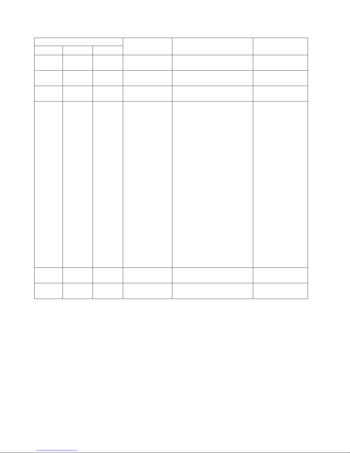
AC power-supply LEDs
Description Action NotesAC DC Error (!)
Off Off On The power supply
has failed.
Off On Off The power supply
has failed.
Off On On The power supply
has failed.
On Off Off Power-supply not
fully seated, faulty
system board, or
the power supply
has failed.
On Off On The power supply
has failed.
On On On The power supply
has failed.
Replace the power supply.
Replace the power supply.
Replace the power supply.
1. Reseat the power supply.
2. Follow actions in the “Power
problems” under the
Troubleshooting tables in the
Problem Determination and
Service Guide.
3. If the OVER SPEC LED on
the light path diagnostics is
lit, follow the actions in “Light
path diagnostics LEDs” on
page 17.
4. If the OVER SPEC LED on
the light path diagnostics is
not lit, check the error LEDs
on the system board and the
IMM2 error messages. Follow
steps in the “Power
problems” under the
Troubleshooting tables in the
Problem Determination and
Service Guide and “Solving
Power problems” in the
Problem Determination and
Service Guide until the
problem is solved.
Replace the power supply.
Replace the power supply.
Typically indicates a
power-supply is not
fully seated.
DC power-supply LEDs
The following illustration shows the locations of the power-supply LEDs on the dc
power supply.
24 IBM System x3550 M4 Type 7914: Installation and User’s Guide
Page 41
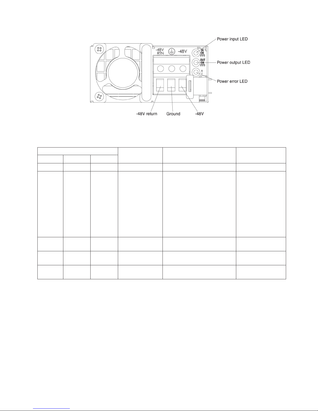
The following table describes the problems that are indicated by various
combinations of the power-supply LEDs on a dc power supply and suggested
actions to correct the detected problems.
DC power-supply LEDs
Description Action NotesIN OK OUT OK Error (!)
On On Off Normal operation.
Off Off Off No dc power to the
server or a problem
with the dc power
source.
Off Off On The power supply
has failed.
Off On Off The power supply
has failed.
Off On On The power supply
has failed.
1. Check the dc power to the
server.
2. Make sure that the power
cord is connected to a
functioning power source.
3. Restart the server. If the error
remains, check the
power-supply LEDs.
4. If the problem remains,
replace the power-supply.
Replace the power supply.
Replace the power supply.
Replace the power supply.
This is a normal
condition when no dc
power is present.
Chapter 1. The System x3550 M4 server 25
Page 42

DC power-supply LEDs
Description Action NotesIN OK OUT OK Error (!)
On Off Off Power-supply not
fully seated, faulty
system board, or
the power supply
has failed.
On Off On The power supply
has failed.
On On On The power supply
has failed.
1. Reseat the power supply.
2. Follow actions in the “Power
problems” under the
Troubleshooting tables in the
Problem Determination and
Service Guide.
3. If the OVER SPEC LED on
the light path diagnostics is
lit, follow the actions in “Light
path diagnostics LEDs” on
page 17.
4. If the OVER SPEC LED on
the light path diagnostics is
not lit, check the error LEDs
on the system board and the
IMM2 error messages. Follow
steps in the “Power
problems” under the
Troubleshooting tables in the
Problem Determination and
Service Guide and “Solving
Power problems” in the
Problem Determination and
Service Guide until the
problem is solved.
Replace the power supply.
Replace the power supply.
Typically indicates a
power-supply is not
fully seated.
26 IBM System x3550 M4 Type 7914: Installation and User’s Guide
Page 43

System pulse LEDs
The following LEDs are on the system board and monitor the system power-on and
power-off sequencing and boot progress (see “System-board LEDs” on page 37 for
the location of these LEDs):
Table 3. System pulse LEDs
LED Description Action
RTMM heartbeat Power-on and power-off
sequencing.
IMM2 heartbeat IMM2 heartbeat boot process. The following steps describe the different stages of the
1. If the LED blinks at 1Hz, it is functioning properly
and no action is necessary.
2. If the LED is not blinking, (trained technician only)
replace the system board.
IMM2 heartbeat sequencing process.
1. When this LED is blinking fast (approximately 4Hz),
this indicates, that the IMM2 code is in the loading
process.
2. When this LED goes off momentarily, this indicates
that the IMM2 code has loaded completely.
3. When this LED goes off momentarily and then
starts blinking slowing (approximately 1Hz), this
indicates that IMM2 is fully operational. You can
now press the power-control button to power-on the
server.
4. If this LED does not blink within 30 seconds of
connecting a power source to the server, (trained
technician only) Replace the system board.
Server power features
When the server is connected to an ac power source but is not turned on, the
operating system does not run, and all core logic except for the integrated
management module II (IMM2) is shut down; however, the server can respond to
requests from IMM2, such as a remote request to turn on the server. The power-on
LED flashes to indicate that the server is connected to an ac power source but is
not turned on.
Turning on the server
Approximately 5 seconds after the server is connected to power, one or more fans
might start running to provide cooling while the server is connected to power and
the power-on button LED will blink quickly. Approximately 5 to 10 seconds after the
server is connected to power, the power-control button becomes active (the
power-on LED will blink slowly), and one or more fans might start running to provide
cooling while the server is connected to power. You can turn on the server by
pressing the power-control button.
The server can also be turned on in any of the following ways:
v If a power failure occurs while the server is turned on, the server will restart
automatically when power is restored.
v If your operating system supports the Wake on LAN feature, the Wake on LAN
feature can turn on the server.
Notes:
1. When 4 GB or more of memory (physical or logical) is installed, some memory
is reserved for various system resources and is unavailable to the operating
Chapter 1. The System x3550 M4 server 27
Page 44

system. The amount of memory that is reserved for system resources depends
on the operating system, the configuration of the server, and the configured PCI
options.
2. Ethernet 1 connector supports Wake on LAN feature.
3. When you turn on the server with the graphical adapters installed, the IBM logo
displays on the screen after approximately 3 minutes. This is normal operation
while the system loads.
Turning off the server
When you turn off the server and leave it connected to power, the server can
respond to requests to the service processor, such as a remote request to turn on
the server. While the server remains connected to power, one or more fans might
continue to run. To remove all power from the server, you must disconnect it from
the power source.
Some operating systems require an orderly shutdown before you turn off the server.
See your operating-system documentation for information about shutting down the
operating system.
Statement 5:
CAUTION:
The power control button on the device and the power switch on the power
supply do not turn off the electrical current supplied to the device. The device
also might have more than one power cord. To remove all electrical current
from the device, ensure that all power cords are disconnected from the power
source.
The server can be turned off in any of the following ways:
v You can turn off the server from the operating system, if your operating system
supports this feature. After an orderly shutdown of the operating system, the
server will turn off automatically.
v You can press the power-control button to start an orderly shutdown of the
operating system and turn off the server, if your operating system supports this
feature.
v If the operating system stops functioning, you can press and hold the
power-control button for more than 4 seconds to turn off the server.
v The server can be turned off by Wake on LAN feature with the following
limitation:
Note: When you install any PCI adapter, the power cords must be disconnected
from the power source before you remove the PCI Express riser-card
assembly and the PCI-X riser-card assembly. Otherwise, the Wake on
LAN feature might not work.
28 IBM System x3550 M4 Type 7914: Installation and User’s Guide
Page 45

v The integrated management module II (IMM2) can turn off the server as an
automatic response to a critical system failure.
Chapter 1. The System x3550 M4 server 29
Page 46

30 IBM System x3550 M4 Type 7914: Installation and User’s Guide
Page 47

Chapter 2. Installing optional devices
This chapter provides detailed instructions for installing optional hardware devices in
the server.
Instructions for IBM Business Partners
In addition to the instructions in this chapter for installing optional hardware devices,
updating firmware and device drivers, and completing the installation, IBM Business
Partners must also complete the following steps:
1. After you have confirmed that the server starts correctly and recognizes the
newly installed devices and that no error LEDs are lit, run the Dynamic System
Analysis (DSA) stress tests. For information about using DSA, see the Problem
Determination and Service Guide.
2. Shut down and restart the server multiple times to ensure that the server is
correctly configured and functions correctly with the newly installed devices.
3. Save the DSA log as a file and send it to IBM. For information about transferring
data and logs, see http://publib.boulder.ibm.com/infocenter/toolsctr/v1r0/
index.jsp?topic=/dsa/dsa_main.html.
4. To ship the server, repackage it in the original undamaged packing material and
observe IBM procedures for shipping.
Support information for IBM Business Partners is available at http://www.ibm.com/
partnerworld/.
How to send DSA data to IBM
Before you send diagnostic data to IBM, read the terms of use at
http://www.ibm.com/de/support/ecurep/terms.html.
You can use any of the following methods to send diagnostic data to IBM:
v Standard upload: http://www.ibm.com/de/support/ecurep/send_http.html
v Standard upload with the system serial number: http://www.ecurep.ibm.com/
app/upload_hw
v Secure upload: http://www.ibm.com/de/support/ecurep/send_http.html#secure
v Secure upload with the system serial number: https://www.ecurep.ibm.com/
app/upload_hw
© Copyright IBM Corp. 2012 31
Page 48
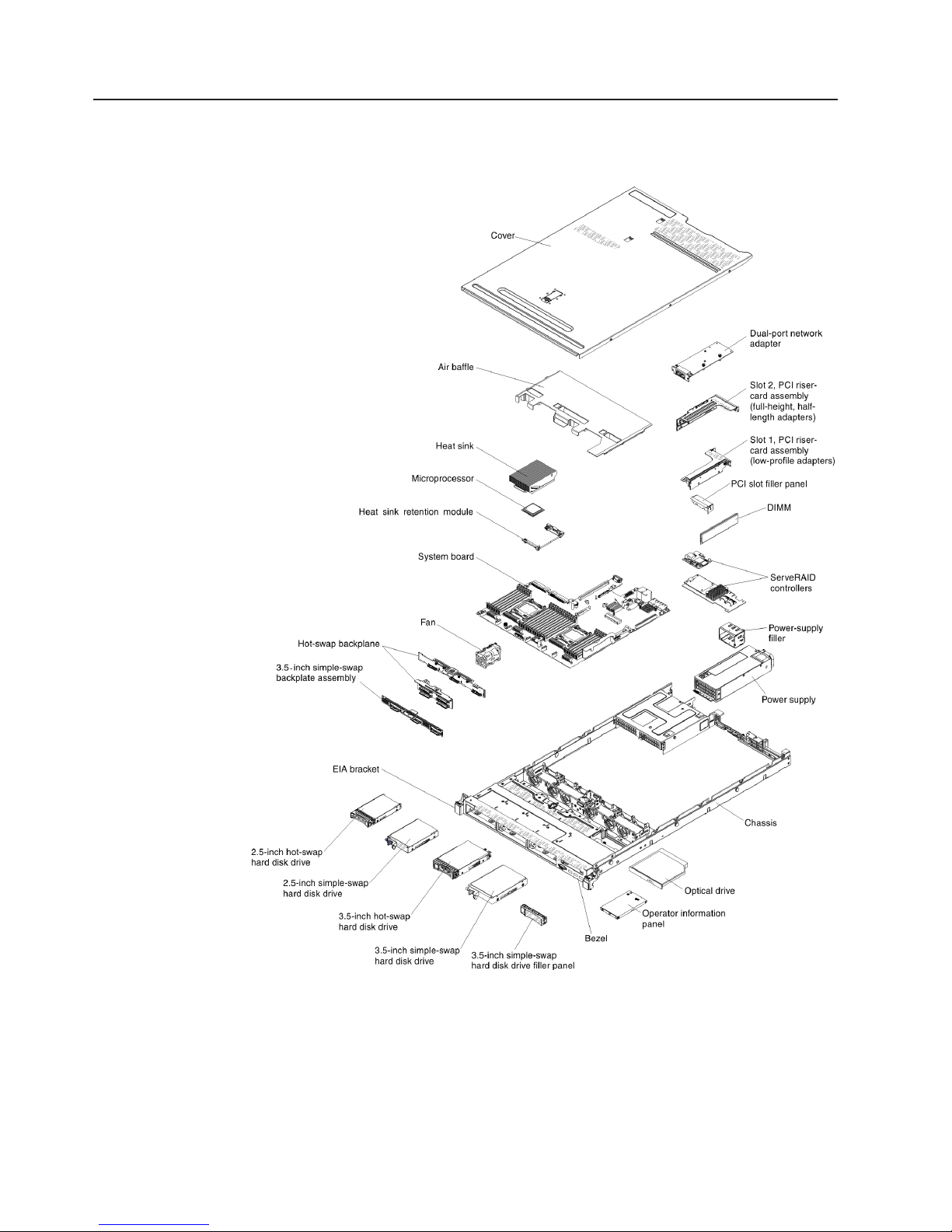
Server components
The following illustration shows the major components in the server. The
illustrations in this document might differ slightly from your hardware.
32 IBM System x3550 M4 Type 7914: Installation and User’s Guide
Page 49

System-board internal connectors
The following illustration shows the internal connectors on the system board.
Chapter 2. Installing optional devices 33
Page 50
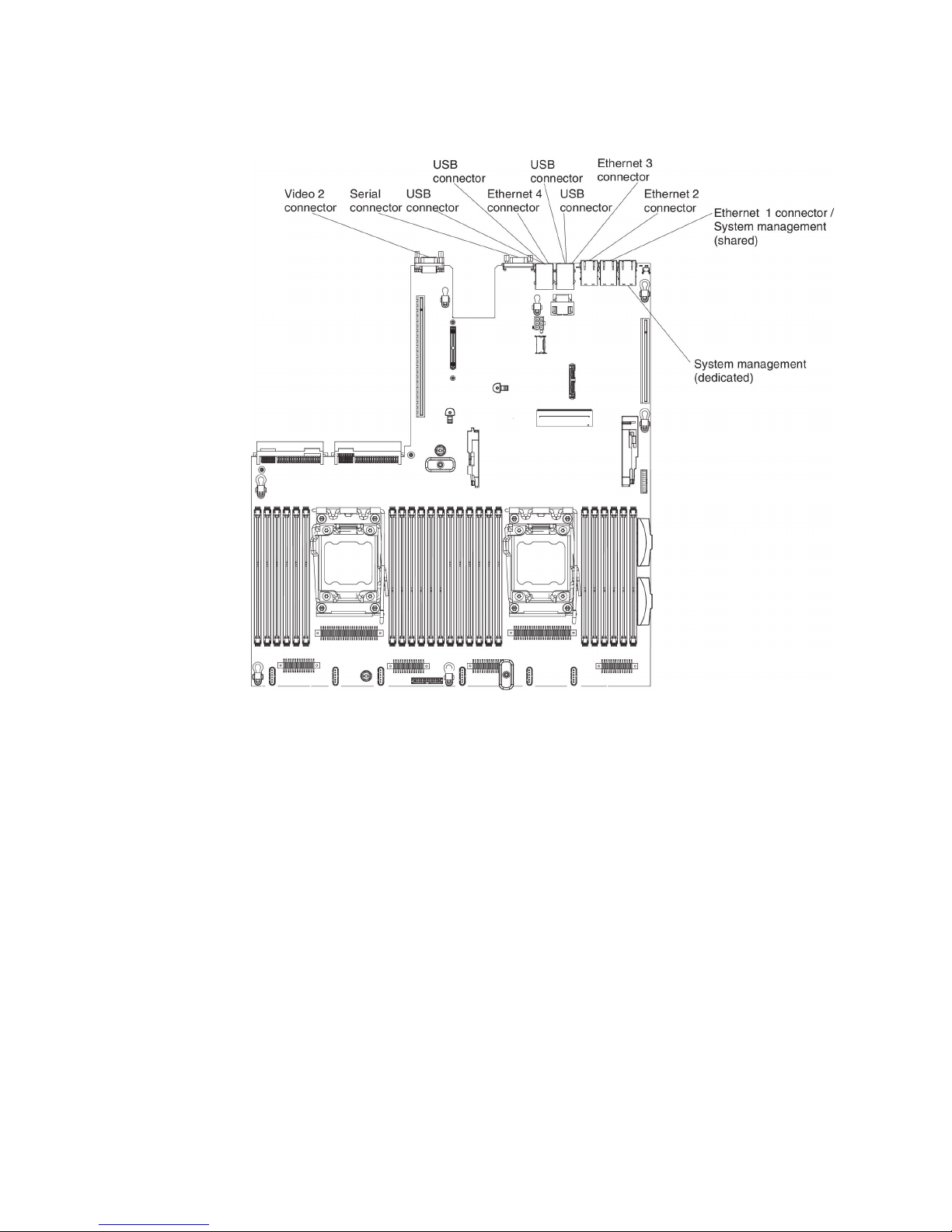
System-board external connectors
The following illustration shows the external connectors on the system board.
34 IBM System x3550 M4 Type 7914: Installation and User’s Guide
Page 51

System-board switches and jumpers
The following illustration shows the location and description of the switches and
jumpers.
Note: If there is a clear protective sticker on the top of the switch blocks, you must
remove and discard it to access the switches.
The following table describes the jumpers on the system board.
Table 4. System board jumpers
Jumper number Jumper name Jumper setting
JP1 CMOS clear jumper
JP2 UEFI boot backup jumper
JP6 System TPM physical
presence jumper
Note: Changing the position of the UEFI boot recovery jumper from pins 1 and 2 to pins 2
and 3 before the server is turned on alters which flash ROM page is loaded. Do not change
the jumper pin position after the server is turned on. This can cause an unpredictable
problem.
v Pins 1 and 2: Normal (default).
v Pins 2 and 3: Clears the real-time
clock (RTC) registry.
v Pins 1 and 2: Normal (default).
Loads the primary server firmware
ROM page.
v Pins 2 and 3: Loads the secondary
(backup) server firmware ROM
page.
v Pins 1 and 2: Normal (default).
v Pins 2 and 3: Indicates a physical
presence to the system TPM.
Chapter 2. Installing optional devices 35
Page 52
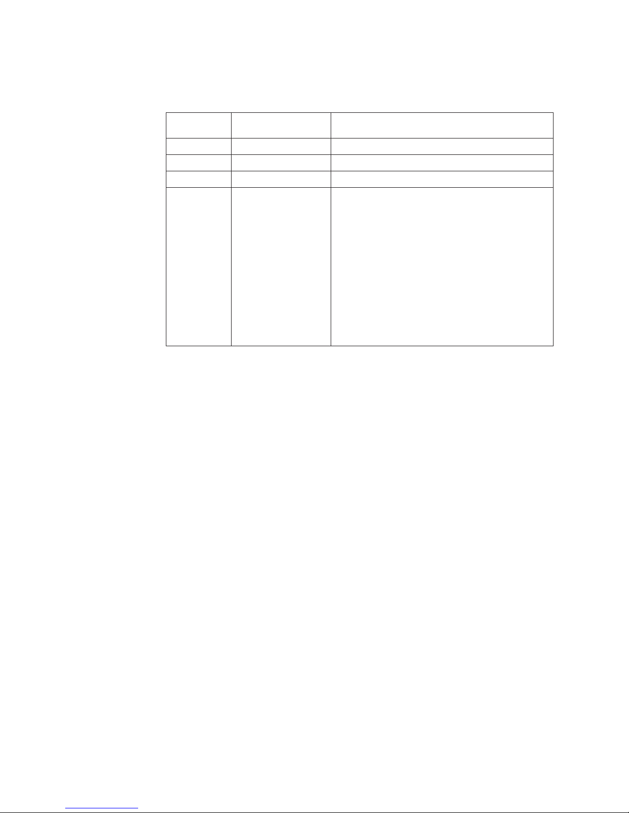
The following table describes the functions of the SW3 switch block on the system
board.
Table 5. System board SW3 switch block definition
Switch
number Default position Description
1 Off Reserved.
2 Off Reserved.
3 Off Reserved.
4 Off Power-on password override. Changing the position
of this switch bypasses the power-on password
check the next time the server is turned on and
starts the Setup utility so that you can change or
delete the power-on password. You do not have to
move the switch back to the default position after
the power-on password in overridden.
Changing the position of this switch does not affect
the administrator password check if an administrator
password is set.
See “Passwords” on page 113 for additional
information about passwords.
Important:
1. Before you change any switch settings or move any jumpers, turn off the server;
then, disconnect all power cords and external cables. Review the information in
vii, “Installation guidelines” on page 38, “Handling static-sensitive devices” on
page 40, and “Turning off the server” on page 28.
2. Any system-board switch or jumper block that is not shown in the illustrations in
this document are reserved.
36 IBM System x3550 M4 Type 7914: Installation and User’s Guide
Page 53

System-board LEDs
The following illustration shows the light-emitting diodes (LEDs) on the system
board.
Chapter 2. Installing optional devices 37
Page 54

System-board optional devices connectors
The following illustration shows the connectors on the system board for
user-installable options.
Installation guidelines
Attention: Static electricity that is released to internal server components when
the server is powered-on might cause the system to halt, which might result in the
loss of data. To avoid this potential problem, always use an electrostatic-discharge
wrist strap or other grounding system when removing or installing a hot-swap
device.
Before you install optional devices, read the following information:
v Make sure that the devices that you are installing are supported. For a list of
supported optional devices for the server, see http://www.ibm.com/systems/info/
x86servers/serverproven/compat/us/.
v Read the safety information that begins on page vii and the guidelines in
“Working inside the server with the power on” on page 40, and “Handling
static-sensitive devices” on page 40. This information will help you work safely.
v When you install your new server, take the opportunity to download and apply
the most recent firmware updates. This step will help to ensure that any known
issues are addressed and that your server is ready to function at maximum levels
of performance. To download firmware updates for your server, go to
http://www.ibm.com/support/fixcentral/.
38 IBM System x3550 M4 Type 7914: Installation and User’s Guide
Page 55

Important: Some cluster solutions require specific code levels or coordinated
code updates. If the device is part of a cluster solution, verify that the
latest level of code is supported for the cluster solution before you
update the code.
For additional information about tools for updating, managing, and deploying
firmware, see the ToolsCenter for System x and BladeCenter at
http://publib.boulder.ibm.com/infocenter/toolsctr/v1r0/index.jsp.
v Before you install optional hardware, make sure that the server is working
correctly. Start the server, and make sure that the operating system starts, if an
operating system is installed, or that a 19990305 error code is displayed,
indicating that an operating system was not found but the server is otherwise
working correctly. If the server is not working correctly, see the Problem
Determination and Service Guide on the IBM System x Documentation CD for
diagnostic information.
v Observe good housekeeping in the area where you are working. Place removed
covers and other parts in a safe place.
v If you must start the server while the server cover is removed, make sure that no
one is near the server and that no tools or other objects have been left inside the
server.
v Do not attempt to lift an object that you think is too heavy for you. If you have to
lift a heavy object, observe the following precautions:
– Make sure that you can stand safely without slipping.
– Distribute the weight of the object equally between your feet.
– Use a slow lifting force. Never move suddenly or twist when you lift a heavy
object.
– To avoid straining the muscles in your back, lift by standing or by pushing up
with your leg muscles.
v Make sure that you have an adequate number of properly grounded electrical
outlets for the server, monitor, and other devices.
v Back up all important data before you make changes to disk drives.
v Have a small flat-blade screwdriver, a small Phillips screwdriver, and a T8 torx
screwdriver available.
v You do not have to turn off the server to install or replace hot-swap power
supplies, hot-swap fans, or hot-plug Universal Serial Bus (USB) devices.
However, you must turn off the server before you perform any steps that involve
removing or installing adapter cables and you must disconnect the power source
from the server before you perform any steps that involve removing or installing a
riser card.
v Blue on a component indicates touch points, where you can grip the component
to remove it from or install it in the server, open or close a latch, and so on.
v Orange on a component or an orange label on or near a component indicates
that the component can be hot-swapped, which means that if the server and
operating system support hot-swap capability, you can remove or install the
component while the server is running. (Orange can also indicate touch points on
hot-swap components.) See the instructions for removing or installing a specific
hot-swap component for any additional procedures that you might have to
perform before you remove or install the component.
v When you are finished working on the server, reinstall all safety shields, guards,
labels, and ground wires.
v For a list of supported optional devices for the server, see http://www.ibm.com/
servers/eserver/serverproven/compat/us/.
Chapter 2. Installing optional devices 39
Page 56

System reliability guidelines
To help ensure proper system cooling and system reliability, make sure that the
following requirements are met:
v Each of the drive bays has a drive or a filler panel and electromagnetic
compatibility (EMC) shield installed in it.
v If the server has redundant power, each of the power-supply bays has a power
supply installed in it.
v There is adequate space around the server to allow the server cooling system to
work properly. Leave approximately 50 mm (2.0 in.) of open space around the
front and rear of the server. Do not place objects in front of the fans. For proper
cooling and airflow, replace the server cover before you turn on the server.
Operating the server for extended periods of time (more than 30 minutes) with
the server cover removed might damage server components.
v You have followed the cabling instructions that come with optional adapters.
v You have replaced a failed fan within 48 hours.
v You have replaced a hot-swap fan within 30 seconds of removal.
v You have replaced a hot-swap drive within 2 minutes of removal.
v You do not operate the server without the air baffle installed. Operating the
server without the air baffle might cause the microprocessor to overheat.
v Microprocessor socket 2 always contains either a socket cover or a
microprocessor and heat sink.
v You have installed the fourth and sixth fans when you installed the second
microprocessor option.
Working inside the server with the power on
Attention: Static electricity that is released to internal server components when
the server is powered-on might cause the server to halt, which might result in the
loss of data. To avoid this potential problem, always use an electrostatic-discharge
wrist strap or other grounding system when you work inside the server with the
power on.
The server supports hot-plug, hot-add, and hot-swap devices and is designed to
operate safely while it is turned on and the server cover is removed. Follow these
guidelines when you work inside a server that is turned on:
v Avoid wearing loose-fitting clothing on your forearms. Button long-sleeved shirts
before working inside the server; do not wear cuff links while you are working
inside the server.
v Do not allow your necktie or scarf to hang inside the server.
v Remove jewelry, such as bracelets, necklaces, rings, and loose-fitting wrist
watches.
v Remove items from your shirt pocket, such as pens and pencils, that could fall
into the server as you lean over it.
v Avoid dropping any metallic objects, such as paper clips, hairpins, and screws,
into the server.
Handling static-sensitive devices
Attention: Static electricity can damage the server and other electronic devices.
To avoid damage, keep static-sensitive devices in their static-protective packages
until you are ready to install them.
40 IBM System x3550 M4 Type 7914: Installation and User’s Guide
Page 57

To reduce the possibility of damage from electrostatic discharge, observe the
following precautions:
v Limit your movement. Movement can cause static electricity to build up around
you.
v The use of a grounding system is recommended. For example, wear an
electrostatic-discharge wrist strap, if one is available. Always use an
electrostatic-discharge wrist strap or other grounding system when working inside
the server with the power on.
v Handle the device carefully, holding it by its edges or its frame.
v Do not touch solder joints, pins, or exposed circuitry.
v Do not leave the device where others can handle and damage it.
v While the device is still in its static-protective package, touch it to an unpainted
metal surface on the outside of the server for at least 2 seconds. This drains
static electricity from the package and from your body.
v Remove the device from its package and install it directly into the server without
setting down the device. If it is necessary to set down the device, put it back into
its static-protective package. Do not place the device on the server cover or on a
metal surface.
v Take additional care when handling devices during cold weather. Heating reduces
indoor humidity and increases static electricity.
Internal cable routing and connectors
Hard disk drive cable connection
The following illustrations show the internal routing and connectors for the
SAS/SATA signal cables.
Notes:
1. To connect the SAS/SATA signal cables, make sure that you first connect the
signal cable, and then the power cable and configuration cable.
2. To disconnect the SAS/SATA signal cables, make sure that you first disconnect
the power cable, and then the signal cable and configuration cable.
Chapter 2. Installing optional devices 41
Page 58
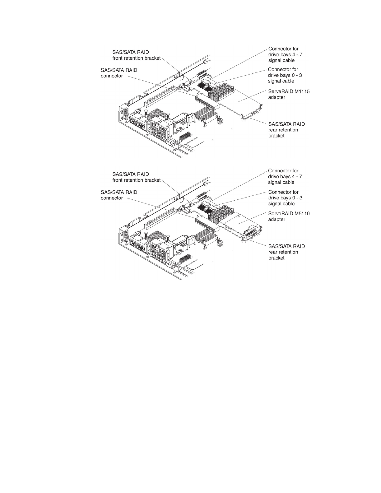
42 IBM System x3550 M4 Type 7914: Installation and User’s Guide
Page 59
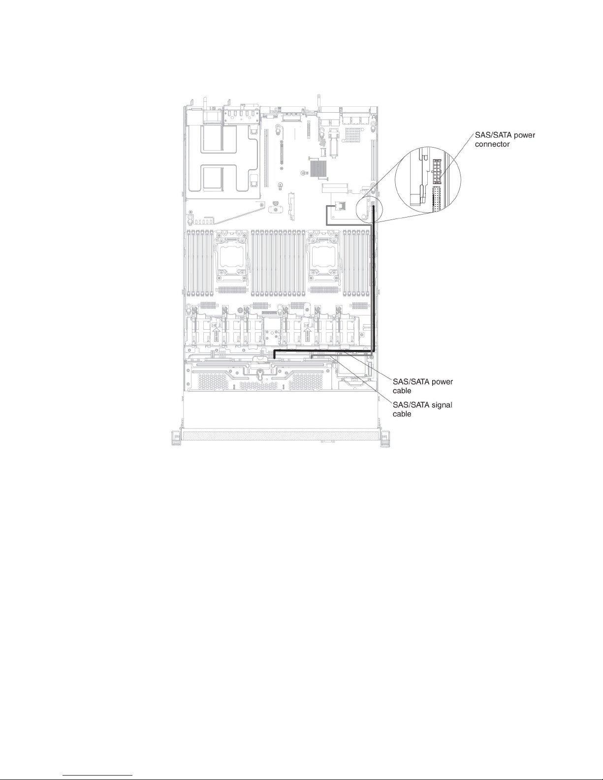
The following illustration shows the internal routing and connectors for the 3.5-inch
simple-swap hard disk drives SATA signal and power cables.
Chapter 2. Installing optional devices 43
Page 60

The following illustration shows the internal routing and connectors for the 3.5-inch
hot-swap hard disk drives SAS/SATA signal, power and configuration cables with
the SAS/SATA adapter installed.
44 IBM System x3550 M4 Type 7914: Installation and User’s Guide
Page 61

The following illustration shows the internal routing and connectors for the
SAS/SATA signal, power and configuration cables with the SAS/SATA adapter
installed.
Chapter 2. Installing optional devices 45
Page 62
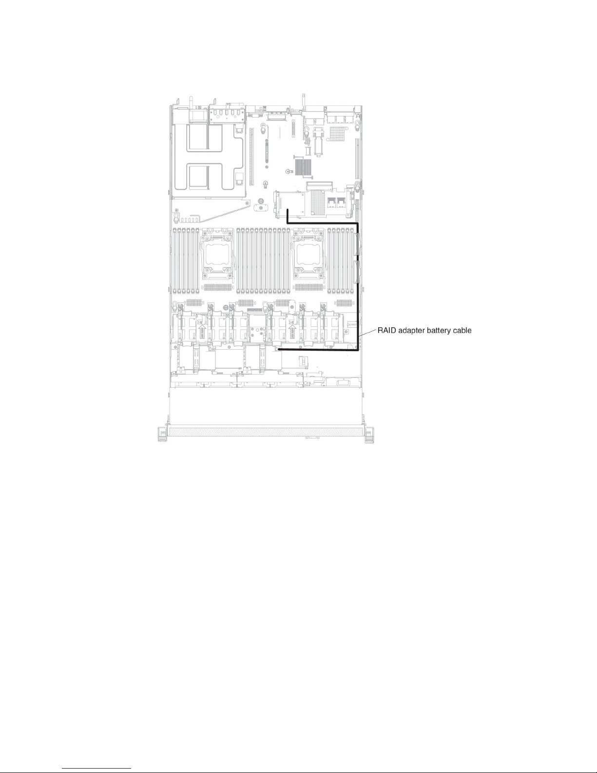
The following illustration shows the internal routing and connectors for the RAID
battery cables with the SAS/SATA adapter installed.
46 IBM System x3550 M4 Type 7914: Installation and User’s Guide
Page 63
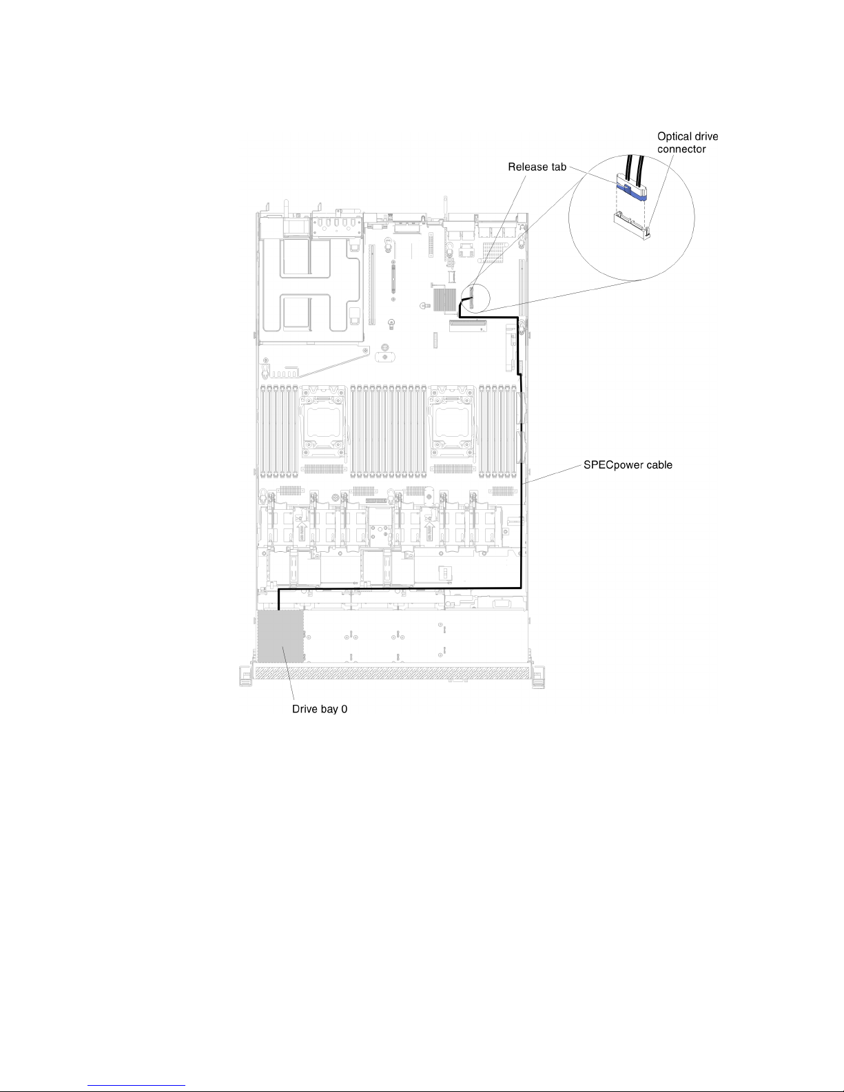
The following illustration shows the internal routing and connectors for the server
models with one 2.5-inch simple-swap hard disk drives.
Chapter 2. Installing optional devices 47
Page 64
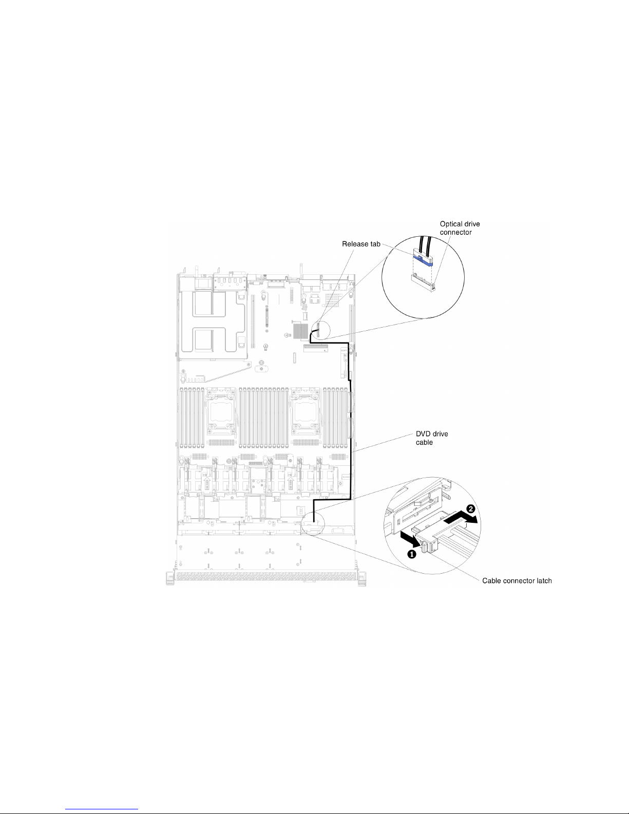
DVD drive cable connection
The following illustration shows the internal routing and connector for the DVD drive
cable.
Notes:
1. To disconnect the optional optical drive cable, you must first press the connector
release tab, and then disconnect the cable from the connector on the system
board. Do not disconnect the cable by using excessive force.
2. Follow the optical drive cable routing as the illustration shows. Make sure that
the cable is not pinched and does not cover any connectors or obstruct any
components on the system board.
48 IBM System x3550 M4 Type 7914: Installation and User’s Guide
Page 65

Operator information panel cable connection
The following illustration shows the internal routing and connector for the operator
information panel cable. The following notes describe additional information you
must consider when you install or remove the operator information panel cable:
v To remove the operator information panel cable, slightly press the cable toward
the fan cage; then, pull to remove the cable from the connector on the system
board. Pulling the cable out of the connector by excessive force might cause
damage to the cable or connector.
v To connect the operator information panel cable on the system board, press
evenly on the cable. Pressing on one side of the cable might cause damage to
the cable or connector.
Chapter 2. Installing optional devices 49
Page 66
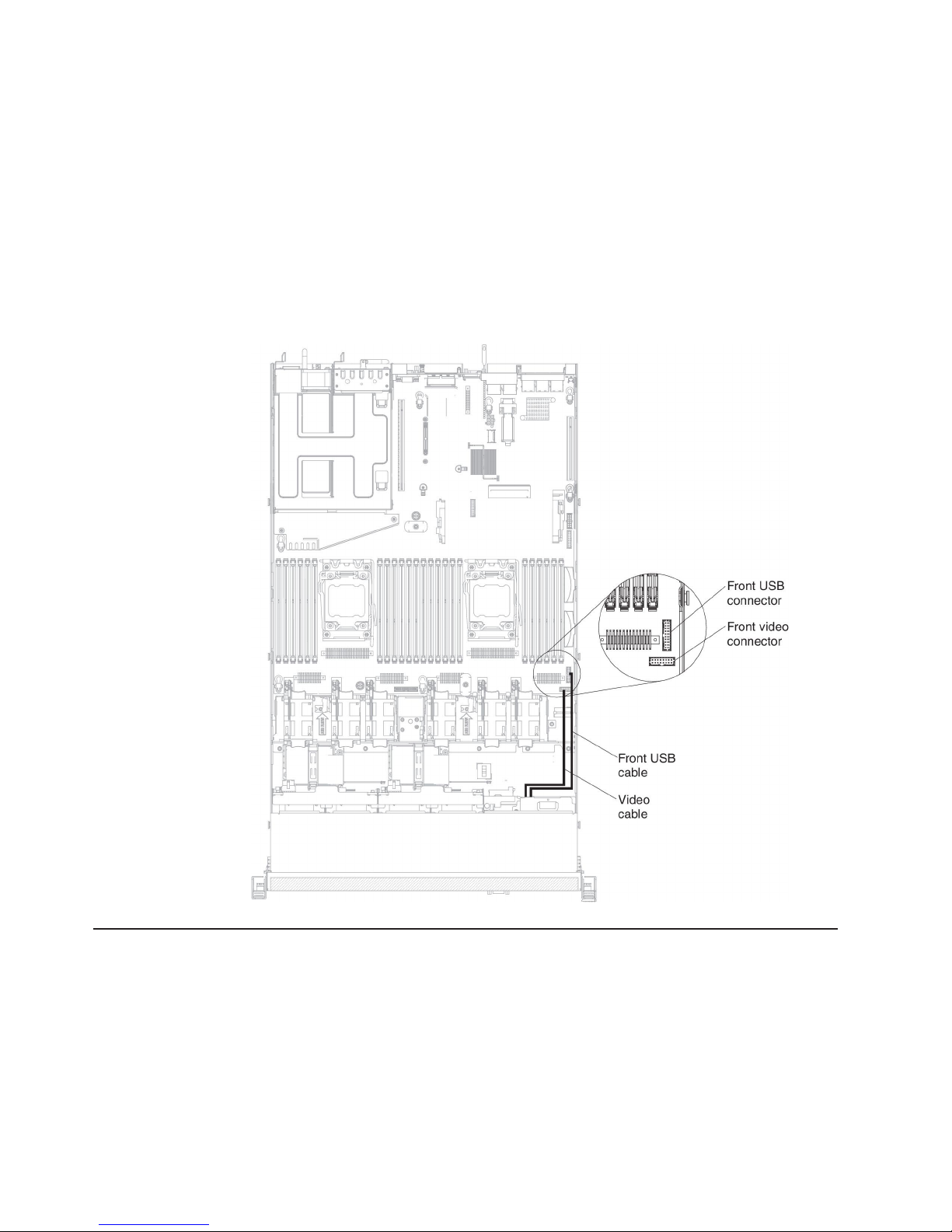
USB and video cable connection
The following illustration shows the internal routing and connectors for the front
USB and video cables. The following notes describe additional information you must
consider when you install or remove the front USB and video cables:
v To remove the front USB and video cables, slightly press the cables toward the
chassis; then, pull to remove the cables from the connectors on the system
board. Pulling the cable out of the connector by excessive force might cause
damage to the cable or connector.
v To connect the front USB and video cables on the system board, press evenly on
the cables. Pressing on one side of the cable might cause damage to the cable
or connector.
Removing the cover
Important: Before you install optional hardware, make sure that the server is
working correctly. Start the server, and make sure that the operating system starts,
if an operating system is installed, or that a 19990305 error code is displayed,
indicating that an operating system was not found but the server is otherwise
working correctly. If the server is not working correctly, see the Problem
Determination and Service Guide for diagnostic information.
To remove the server cover, complete the following steps:
50 IBM System x3550 M4 Type 7914: Installation and User’s Guide
Page 67
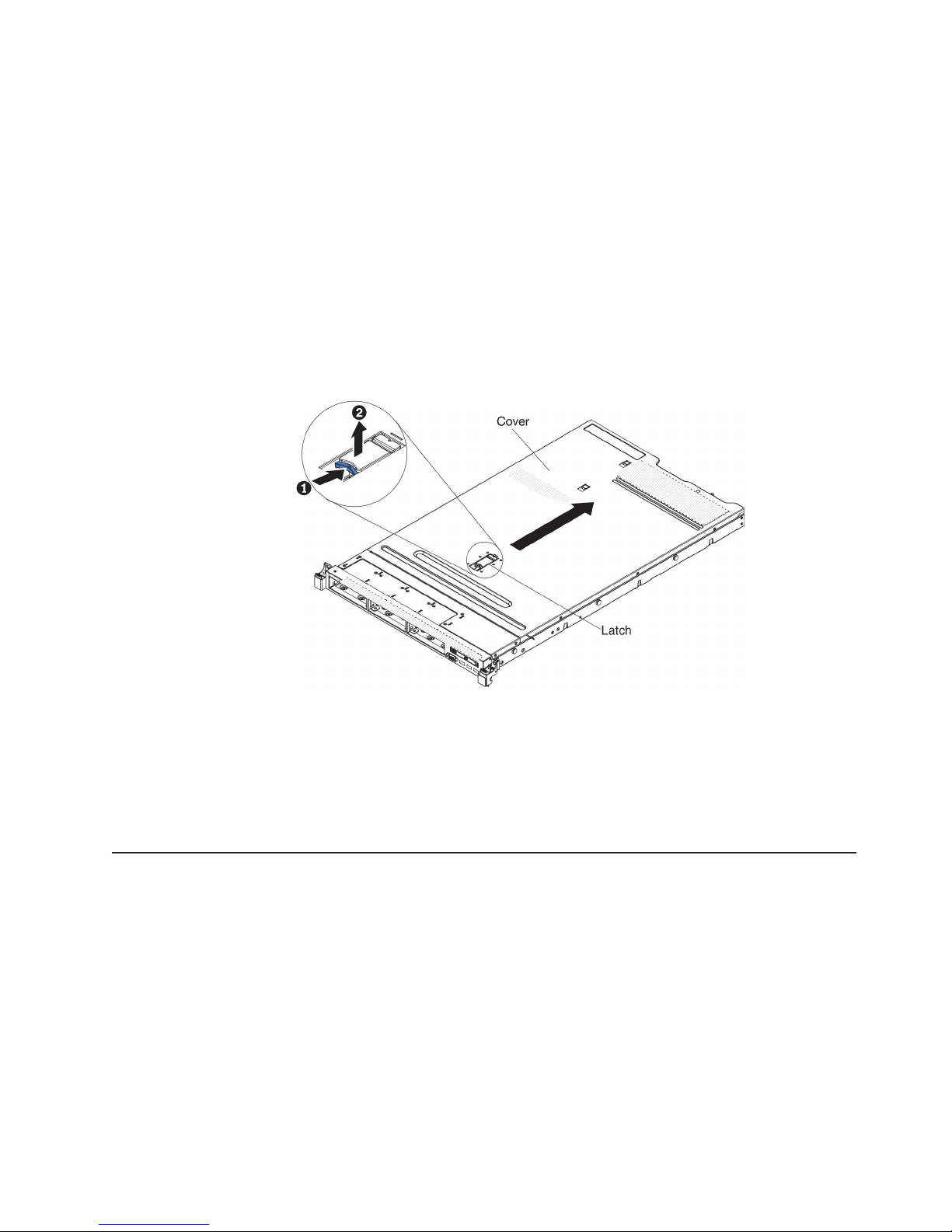
1. Read the safety information that begins on page vii and “Installation guidelines”
on page 38.
2. Turn off the server and peripheral devices and disconnect the power cords and
all external cables, if necessary.
Note: When you disconnect the power source from the server, you lose the
ability to view the LEDs because the LEDs are not lit when the power
source is removed. Before you disconnect the power source, make a
note of which LEDs are lit, including the LEDs that are lit on the
operation information panel, on the light path diagnostics panel, and
LEDs inside the server on the system board; then, see the Problem
Determination and Service Guide for information about how to solve the
problem.
3. If the server has been installed in a rack, slide the server out from the rack
enclosure.
4. Pull up firmly on the blue latch on the top (in the center of the front of the
server) of the cover and slide the cover toward the rear of the server until the
cover has disengaged from the chassis.
5. Lift the server cover off the server and set it aside.
Attention: For proper cooling and airflow, replace the server cover before you
turn on the server.
Removing the air baffle
To remove the air baffle, complete the following steps:
1. Read the safety information that begins on page vii and “Installation guidelines”
on page 38.
2. Turn off the server and peripheral devices and disconnect the power cords and
all external cables, if necessary.
3. Remove the cover (see “Removing the cover” on page 50).
4. Grasp the air baffle, disengage pins from pin holes; then, lift the air baffle up.
Chapter 2. Installing optional devices 51
Page 68

Installing drives
5. Remove the air baffle from the server and set it aside.
Attention: For proper cooling and airflow, replace the air baffle before you
turn on the server. Operating the server with the air baffle removed might
damage server components.
The following notes describe the type of drives that the server supports and other
information that you must consider when you install a drive.
v Make sure that the devices that you are installing are supported. For a list of
supported optional devices for the server, see http://www.ibm.com/systems/info/
x86servers/serverproven/compat/us/.
v Locate the documentation that comes with the drive and follow those instructions
in addition to the instructions in this chapter.
v Make sure that you have all the cables and other equipment that are specified in
the documentation that comes with the drive.
v Select the bay in which you want to install the drive.
v Check the instructions that come with the drive to determine whether you have to
set any switches or jumpers on the drive. If you are installing a SAS or SATA
hard disk drive, be sure to set the SAS or SATA ID for that device.
v The hot-swap server models support up to eight 2.5-inch or three 3.5-inch
hot-swap SAS or SATA hard disk drives.
v The simple-swap server models support up to three 3.5-inch simple-swap SATA
hard disk drives.
v The electromagnetic interference (EMI) integrity and cooling of the server are
protected by having all bays and PCI and PCI Express slots covered or
occupied. When you install a drive, PCI, or PCI Express adapter, save the EMC
shield and filler panel from the bay or PCI adapter or PCI Express adapter slot
cover in the event that you later remove the device.
Installing a hot-swap hard disk drive
To install a hot-swap SAS or SATA hard disk drive, complete the following steps.
Note: If you have only one hard disk drive, you must install it in the upper-left bay.
1. Read the safety information that begins on page vii and “Installation guidelines”
on page 38.
52 IBM System x3550 M4 Type 7914: Installation and User’s Guide
Page 69

2. Remove the filler panel from the empty drive bay. Keep the filler panel in a safe
place.
3. Touch the static-protective package that contains the drive to any unpainted
metal surface on the server; then, remove the drive from the package and place
it on a static-protective surface.
4. Install the hard disk drive in the drive bay:
a. Make sure that the tray handle is in the open (unlocked) position.
b. Align the drive with the guide rails in the bay.
c. Gently push the drive into the bay until the drive stops.
d. Rotate the tray handle to the closed (locked) position.
e. Check the hard disk drive status LED to verify that the hard disk drive is
operating correctly. If the yellow hard disk drive status LED of a drive is lit
continuously, that drive is faulty and must be replaced. If the green hard disk
drive activity LED is flashing, the drive is being accessed.
Note: If the server is configured for RAID operation using a ServeRAID
adapter, you might have to reconfigure your disk arrays after you
install hard disk drives. See the ServeRAID adapter documentation
for additional information about RAID operation and complete
instructions for using the ServeRAID adapter.
5. If you are installing additional hot-swap hard disk drives, do so now.
If you have other devices to install or remove, do so now. Otherwise, go to
“Completing the installation” on page 101.
IDs for 2.5-inch hot-swap hard disk drives
The hot-swap-drive ID that is assigned to each drive is printed on the front of the
server. The following illustration shows the location of the IDs of the hard disk
drives. The ID numbers and the drive bay numbers are the same.
Chapter 2. Installing optional devices 53
Page 70
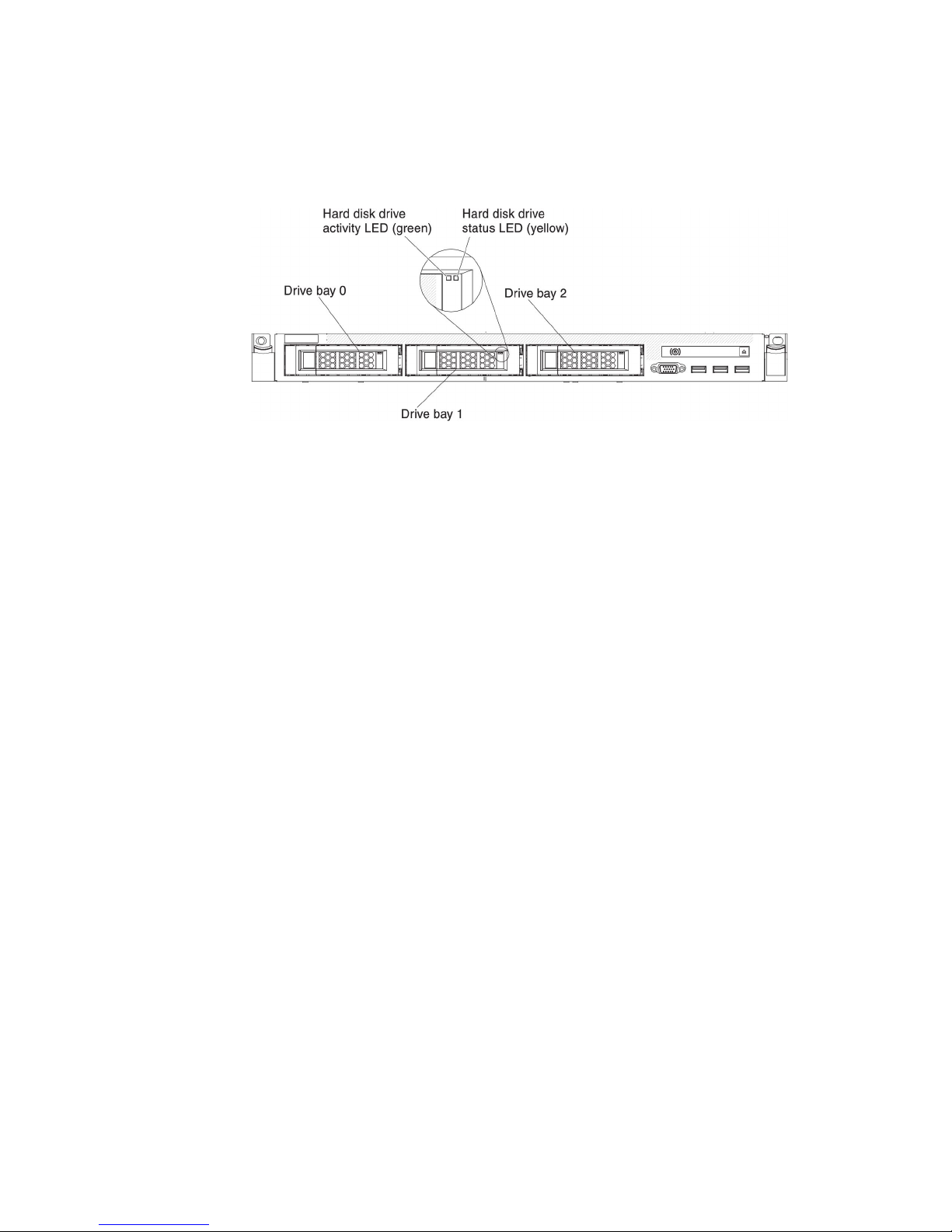
IDs for 3.5-inch hot-swap hard disk drives
The hot-swap-drive ID that is assigned to each drive is printed on the front of the
server. The following illustration shows the location of the IDs of the hard disk
drives. The ID numbers and the drive bay numbers are the same.
Installing a simple-swap hard disk drive
You must turn off the server before installing simple-swap drives in the server.
Before you install a simple-swap SATA hard disk drive, read the following
information.
v Make sure that the devices that you are installing are supported. For a list of
supported optional devices for the server, see http://www.ibm.com/systems/info/
x86servers/serverproven/compat/us/.
v Locate the documentation that comes with the hard disk drive and follow those
instructions in addition to the instructions in this chapter.
v Make sure that you have all the cables and other equipment that are specified in
the documentation that comes with the drive.
v Select the bay in which you want to install the drive.
v Check the instructions that come with the drive to determine whether you have to
set any switches or jumpers on the drive. If you are installing a SATA device, be
sure to set the SATA ID for that device.
v You can install up to three 3.5-inch simple-swap SATA hard disk drives in the
server. Do not install hot-swap drives into a simple-swap server model, it is not
supported.
v You can install one 2.5-inch simple-swap SATA hard disk drives in bay 0 in the
server. Do not install hot-swap drives into a simple-swap server model, it is not
supported.
v The simple-swap server models are available only in non-RAID configurations.
v The electromagnetic interference (EMI) integrity and cooling of the server are
protected by having all bays and PCI and PCI Express slots covered or
occupied. When you install a drive, PCI, or PCI Express adapter, save the EMC
shield and filler panel from the bay or PCI or PCI Express adapter slot cover in
the event that you later remove the device.
To install a simple-swap SATA hard disk drive, complete the following steps:
1. Read the safety information that begins on page vii and “Installation guidelines”
on page 38.
2. Turn off the server and peripheral devices and disconnect the power cords and
all external cables.
3. Remove the filler panel from the empty drive bay.
54 IBM System x3550 M4 Type 7914: Installation and User’s Guide
Page 71

4. Touch the static-protective package that contains the drive to any unpainted
metal surface on the server; then, remove the drive from the package and place
it on a static-protective surface.
5. Install the hard disk drive in the drive bay:
a. Grasp the black drive handle and slide the blue release latch to the right
and align the drive assembly with the guide rails in the bay.
b. Gently push the drive into the bay until the drive stops.
6. Reinstall the drive bay filler panel that you removed earlier.
7. If you are installing additional simple-swap hard disk drives, do so now.
IDs for 2.5-inch simple-swap hard disk drives
The simple-swap-drive ID that is assigned to each drive is printed on the front of
the server. The following illustration shows the location of the IDs of the hard disk
drives. The ID numbers and the drive bay numbers are the same.
IDs for 3.5-inch simple-swap hard disk drives
The simple-swap-drive ID that is assigned to each drive is printed on the front of
the server. The following illustration shows the location of the IDs of the
simple-swap hard disk drives. The ID numbers and the drive bay numbers are the
same.
Chapter 2. Installing optional devices 55
Page 72

Installing an optional DVD drive
To install an optional DVD drive, complete the following steps:
1. Read the safety information that begins on page vii and “Installation guidelines”
on page 38.
2. Turn off the server and peripheral devices and disconnect the power cords and
all external cables.
Note: When you disconnect the power source from the server, you lose the
ability to view the LEDs because the LEDs are not lit when the power
source is removed. Before you disconnect the power source, make a
note of which LEDs are lit, including the LEDs that are lit on the
operation information panel, on the light path diagnostics panel, and
LEDs inside the server on the system board; then, see the Problem
Determination and Service Guide for information about how to solve the
problem.
3. Remove the cover (see “Removing the cover” on page 50).
4. Remove the optical drive filler panel if it is installed. Locate the blue release
tab on the rear of the optical drive filler panel; then, while you press the tab,
push the optical drive filler panel out of the drive bay.
5. Remove the retention clip from the side of the optical drive filler panel. Save
the optical drive filler panel for future use.
Note: If you are installing a drive that contains a laser, observe the following
56 IBM System x3550 M4 Type 7914: Installation and User’s Guide
safety precautions.
Page 73

Statement 3:
CAUTION:
When laser products (such as CD-ROMs, DVD drives, fiber optic devices,
or transmitters) are installed, note the following:
v Do not remove the covers. Removing the covers of the laser product
could result in exposure to hazardous laser radiation. There are no
serviceable parts inside the device.
v Use of controls or adjustments or performance of procedures other
than those specified herein might result in hazardous radiation
exposure.
DANGER
Some laser products contain an embedded Class 3A or Class 3B laser
diode. Note the following.
Laser radiation when open. Do not stare into the beam, do not view
directly with optical instruments, and avoid direct exposure to the
beam.
6. Touch the static-protective package that contains the new optical drive to any
unpainted metal surface on the server; then, remove the optical drive from the
package and place it on a static-protective surface.
7. Follow the instructions that come with the DVD drive to set any jumpers or
switches.
8. Attach the drive retention clip that you removed from the optical drive filler
panel to the side of the DVD drive.
Chapter 2. Installing optional devices 57
Page 74
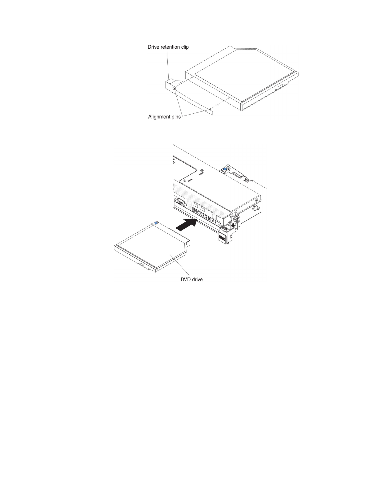
9. Align the drive in the drive bay and slide the drive into the optical drive bay
until the drive clicks into place.
10. Connect the DVD drive cable (see “Installing the DVD drive cable” on page
75).
The following illustration shows the cable routing for the DVD drive:
58 IBM System x3550 M4 Type 7914: Installation and User’s Guide
Page 75
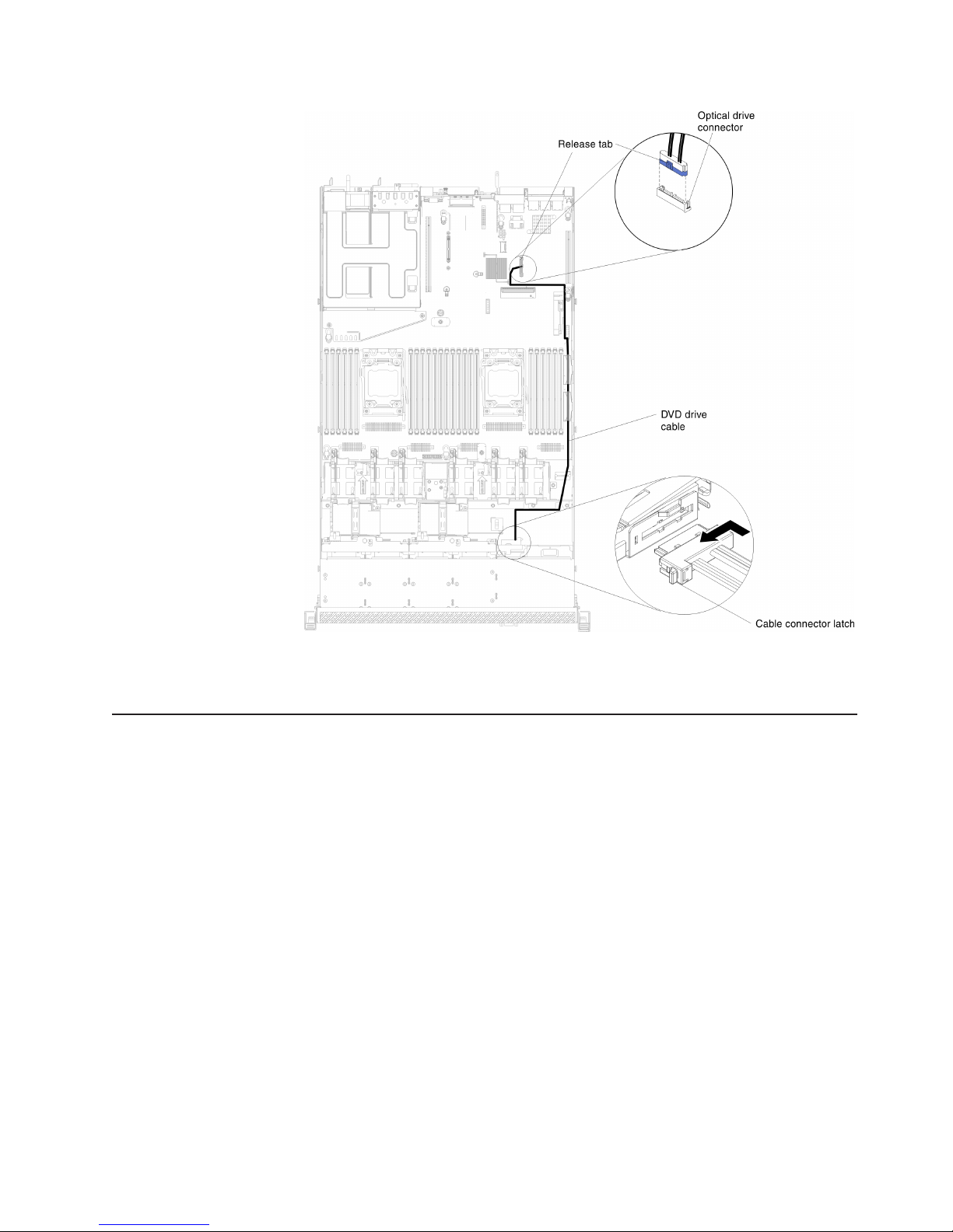
If you have other devices to install or remove, do so now. Otherwise, go to
“Completing the installation” on page 101.
Installing a memory module
The following notes describe the types of DIMMs that the server supports and other
information that you must consider when you install DIMMs.
v When you install or remove DIMMs, the server configuration information
changes. When you restart the server, the system displays a message that
indicates that the memory configuration has changed.
v The server supports only industry-standard double-data-rate 3 (DDR3), 800,
1066, 1333, or 1600 MHz, PC3-6400, PC3-8500, PC3-10600, or PC3-12800
registered or unbuffered, synchronous dynamic random-access memory
(SDRAM) dual inline memory modules (DIMMs) with error correcting code (ECC).
See http://www.ibm.com/systems/info/x86servers/serverproven/compat/us/ for a
list of supported memory modules for the server.
– The specifications of a DDR3 DIMM are on a label on the DIMM, in the
following format.
ggggg eRxff PC3v-wwwwwm-aa-bb-ccd
where:
ggggg is the total capacity of the DIMM (for example, 1GB, 2GB, or 4GB)
eR is the number of ranks
1R = single-rank
2R = dual-rank
Chapter 2. Installing optional devices 59
Page 76

4R = quad-rank
xff is the device organization (bit width)
x4 = x4 organization (4 DQ lines per SDRAM)
x8 = x8 organization
x16 = x16 organization
v is the SDRAM and support component supply voltage (VDD)
Blank = 1.5 V specified
L = 1.35 V specified, 1.5 V operable
Note: Values for these voltages are ‘specified’ which means the device
characteristics such as timing are supported at this voltage.
Values are ‘operable’ which means that the devices can be
operated safely at this voltage. However, device characteristics
such as timing may not be guaranteed. All devices must be
‘tolerant’ of the highest DDR3 nominal voltage of 1.5 V, meaning
that they may not operate at 1.5 V but may be powered at that
voltage without damage to the devices.
wwwww is the DIMM bandwidth, in MBps
6400 = 6.40 GBps (DDR3-800 SDRAMs, 8-byte primary data bus)
8500 = 8.53 GBps (DDR3-1066 SDRAMs, 8-byte primary data bus)
10600 = 10.66 GBps (DDR3-1333 SDRAMs, 8-byte primary data bus)
12800 = 12.80 GBps (DDR3-1600 SDRAMs, 8-byte primary data bus)
m is the DIMM type
E = Unbuffered DIMM (UDIMM) with ECC (x72-bit module data bus)
L = Load Reduction DIMM (LRDIMM)
R = Registered DIMM (RDIMM)
U = Unbuffered DIMM with no ECC (x64-bit primary data bus)
aa is the CAS latency, in clocks at maximum operating frequency
bb is the JEDEC SPD Revision Encoding and Additions level
cc is the reference design file for the design of the DIMM
d is the revision number of the reference design of the DIMM
Note: To determine the type of a DIMM, see the label on the DIMM. The
information on the label is in the format xxxxx nRxxx PC3v-xxxxxx-xx-xxxxx. The numeral in the sixth numerical position indicates whether the
DIMM is single-rank (n=1), dual-rank (n=2), or quad-rank (n=4).
v The following rules apply to DDR3 RDIMM speed as it relates to the number of
RDIMMs in a channel:
– When you install 1 RDIMM per channel, the memory runs at 1600 MHz
– When you install 2 RDIMMs per channel, the memory runs at 1600 MHz
– When you install 3 RDIMMs per channel, the memory runs at 1066 MHz
– All channels in a server run at the fastest common frequency
– Do not install registered, unbuffered, and load reduction DIMMs in the same
server
v The maximum memory speed is determined by the combination of the
microprocessor, DIMM speed, DIMM type, Operating Modes in UEFI settings,
and the number of DIMMs installed in each channel.
60 IBM System x3550 M4 Type 7914: Installation and User’s Guide
Page 77

v In two-DIMM-per-channel configuration, a server with an Intel Xeon™E5-2600
series microprocessor automatically operates with a maximum memory speed of
up to 1600 MHz when the following condition is met:
– Two 1.35 V single-rank, dual-ranl, or quad-rank UDIMMs, RDIMMs or
LRDIMMs are installed in the same channel. In the Setup utility, Memory
speed is set to Max performance and LV-DIMM power is set to Enhance
performance mode. The 1.35 V UDIMMs, RDIMMs or LRDIMMs will function
at 1.5 V.
v The server supports a maximum of 16 dual-rank UDIMMs. The server supports
up to two UDIMMs per channel.
v The server supports a maximum of 24 single-rank, dual-rank, or 16 quad-rank
RDIMMs. The server does not support three quad-rank RDIMMs in the same
channel.
v The following table shows an example of the maximum amount of memory that
you can install using ranked DIMMs:
Table 6. Maximum memory installation using ranked DIMMs
Number of
DIMMs DIMM type DIMM size Total memory
16 Dual-rank UDIMMs 4 GB 64 GB
24 Single-rank RDIMMs 2 GB 48 GB
24 Single-rank RDIMMs 4 GB 96 GB
24 Dual-rank RDIMMs 8 GB 192 GB
24 Dual-rank RDIMMs 16 GB 384 GB
16 Quad-rank RDIMMs 16 GB 256 GB
24 Quad-rank LRDIMMs 32 GB 768 GB
v The UDIMM option that is available for the server is 4 GB. The server supports a
minimum of 4 GB and a maximum of 64 GB of system memory using UDIMMs.
v The RDIMM options that are available for the server are 2 GB, 4 GB, 8 GB, and
16 GB. The server supports a minimum of 2 GB and a maximum of 384 GB of
system memory using RDIMMs.
v The LRDIMM option that is available for the server is 32 GB. The server supports
a minimum of 32 GB and a maximum of 768 GB of system memory using
LRDIMMs.
Note: The amount of usable memory is reduced depending on the system
configuration. A certain amount of memory must be reserved for system
resources. To view the total amount of installed memory and the amount
of configured memory, run the Setup utility. For additional information, see
Chapter 3, “Configuring the server,” on page 105.
v A minimum of one DIMM must be installed for each microprocessor. For
example, you must install a minimum of two DIMMs if the server has two
microprocessors installed. However, to improve system performance, install a
minimum of four DIMMs for each microprocessor.
v DIMMs in the server must be the same type (RDIMM, UDIMM, or LRDIMM) to
ensure that the server will operate correctly.
v When you install one quad-rank DIMM in a channel, install it in the DIMM
connector furthest away from the microprocessor.
Chapter 2. Installing optional devices 61
Page 78
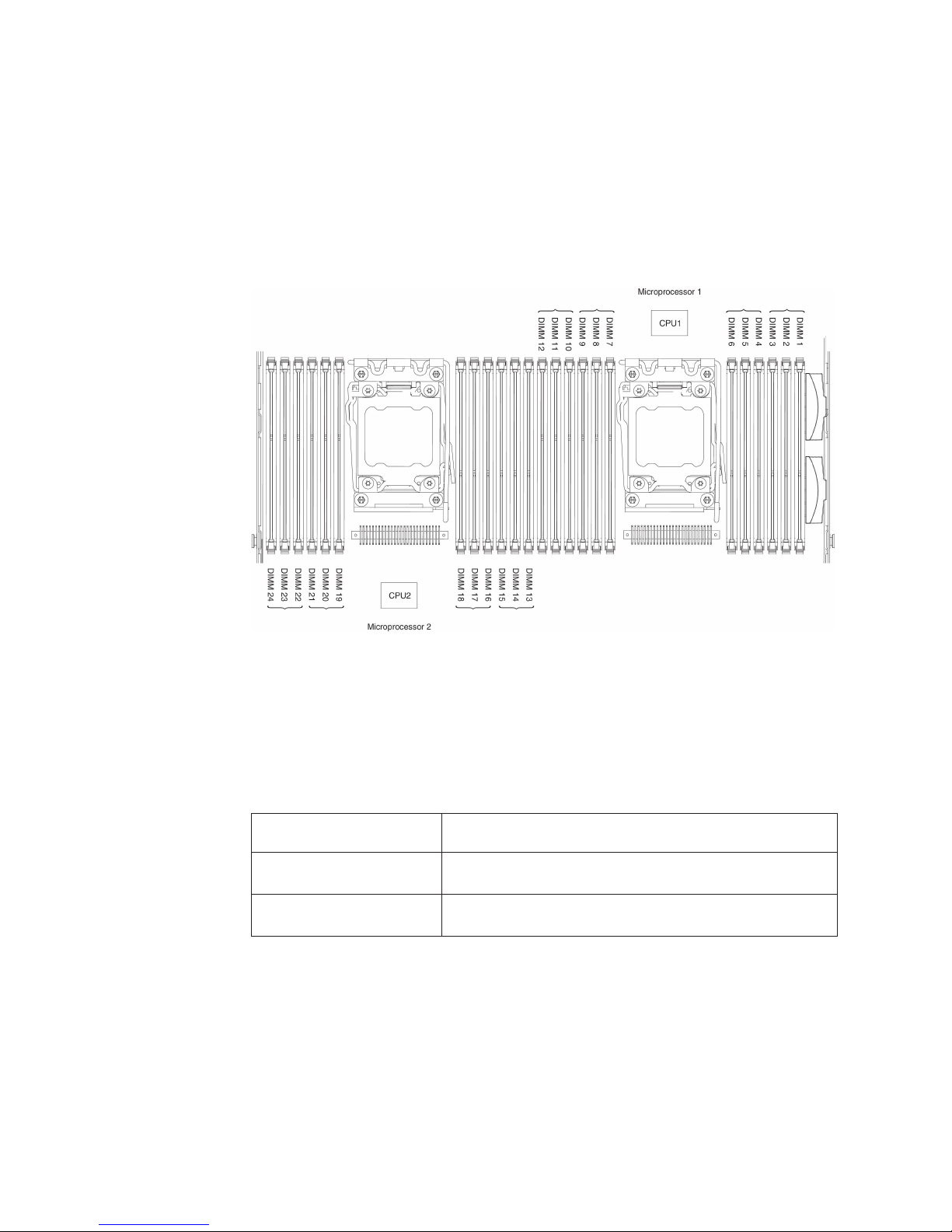
Notes:
1. You can install DIMMs for microprocessor 2 as soon as you install
microprocessor 2; you do not have to wait until all of the DIMM slots for
microprocessor 1 are filled.
2. DIMM slots 13-24 are reserved for microprocessor 2; thus, DIMM slots 13-24
are enabled when microprocessor 2 is installed.
The following illustration shows the location of the DIMM connectors on the system
board.
DIMM installation sequence
Depending on the server model, the server may come with a minimum of one 2 GB
or 4 GB DIMM installed in slot 1. When you install additional DIMMs, install them in
the order shown in the following table to optimize system performance. In general,
all three channels on the memory interface for each microprocessor can be
populated in any order and have no matching requirements.
Table 7. Normal mode DIMM installation sequence
Number of installed
microprocessor DIMM connector population sequence
One microprocessor
installed
Two microprocessors
installed
Memory mirrored channel
Memory mirrored channel mode replicates and stores data on two pairs of DIMMs
within two channels simultaneously. If a failure occurs, the memory controller
switches from the primary pair of memory DIMMs to the backup pair of DIMMs. You
can enable memory mirrored channel in the Setup utility (see “Starting the Setup
utility” on page 109). When you use the memory mirrored channel feature, consider
the following information:
1, 4, 9, 12, 2, 5, 8, 11, 3, 6, 7, 10
1, 13, 4, 16, 9, 21, 12, 24, 2, 14, 5, 17, 8, 20, 11, 23, 3, 15,
6, 18, 7, 19, 10, 22
62 IBM System x3550 M4 Type 7914: Installation and User’s Guide
Page 79
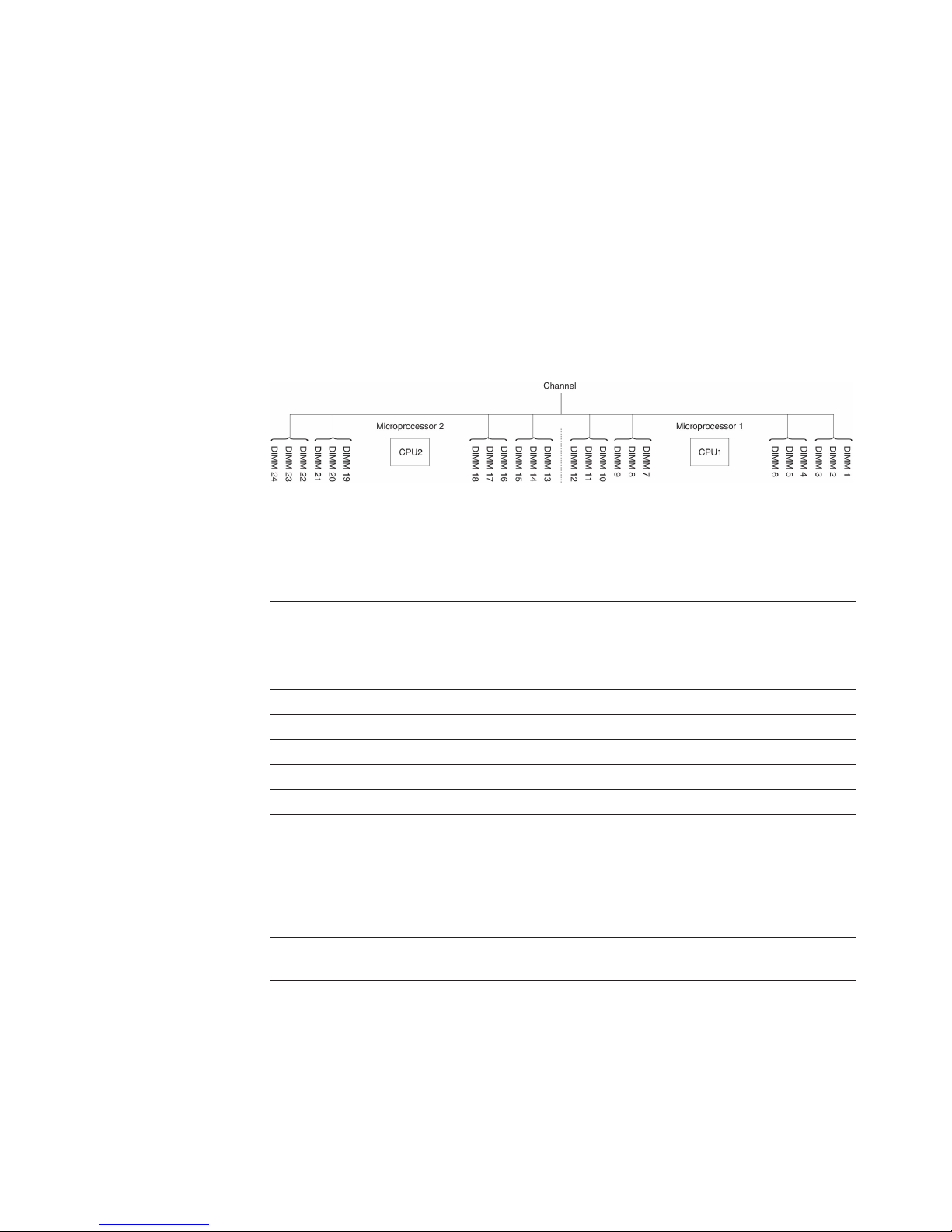
v When you use memory mirrored channel, you must install a pair of DIMMs at a
time. The two DIMMs in each pair must be identical in size, type, and rank
(single, dual, or quad), and organization, but not in speed. The channels run at
the speed of the slowest DIMM in any of the channels.
v The maximum available memory is reduced to half of the installed memory when
memory mirrored channel is enabled. For example, if you install 64 GB of
memory using RDIMMs, only 32 GB of addressable memory is available when
you use memory mirrored channel.
v For UDIMMs, DIMM connectors 3, 6, 7, and 10 for microprocessor 1 and DIMM
connectors 15, 18, 19, and 22 for microprocessor 2 are not used in memory
mirrored channel mode.
The following diagram lists the DIMM connectors on each memory channel.
Figure 1. Connectors on each memory channel
The following table shows the installation sequence for memory mirrored channel
mode:
Table 8. Memory mirrored channel mode DIMM population sequence
Number of DIMMs
First pair of DIMMs 1 1, 4
Second pair of DIMMs 1 9, 12
Third pair of DIMMs 1 2, 5
Fourth pair of DIMMs 1 8, 11
Fifth pair of DIMMs 1 3, 6
Sixth pair of DIMMs 1 7, 10
Seventh pair of DIMMs 2 13, 16
Eighth pair of DIMMs 2 21, 24
Ninth pair of DIMMs 2 14, 17
Tenth pair of DIMMs 2 20, 23
Eleventh pair of DIMMs 2 15, 18
Twelfth pair of DIMMs 2 19, 22
Note: DIMM connectors 3, 6, 7, 10, 15, 18, 19, and 22 are not used in memory mirrored
channel mode when UDIMMs are installed in the server.
Memory rank sparing
The memory rank sparing feature disables the failed memory from the system
configuration and activates a rank sparing DIMM to replace the failed active DIMM.
You can enable either rank sparing memory or memory mirrored channel in the
Setup utility (see “Starting the Setup utility” on page 109). When you use the
memory rank sparing feature, consider the following information:
Number of installed
microprocessor DIMM connector
Chapter 2. Installing optional devices 63
Page 80

v The memory rank sparing feature is supported on server models with an Intel
Xeon™E5-2600 series microprocessor.
v The maximum available memory is reduced when memory rank sparing mode is
enabled.
The following diagram lists the DIMM connectors on each memory channel.
Figure 2. Connectors on each memory channel
Follow the installation sequence for rank sparing mode:
v Install at least one quad-rank DIMM in a channel.
v Install at least two single-rank or dual-rank DIMMs in a channel.
Table 9. Memory rank sparing mode DIMM population sequence
Number of installed
Number of DIMMs
First pair of DIMMs 1 1, 2
Second pair of DIMMs 1 4, 5
Third pair of DIMMs 1 8, 9
Fourth pair of DIMMs 1 11, 12
Fifth pair of DIMMs 1 7, 10
Sixth pair of DIMMs 1 3, 6
Seventh pair of DIMMs 2 13, 14
Eighth pair of DIMMs 2 16, 17
Ninth pair of DIMMs 2 20, 21
Tenth pair of DIMMs 2 23, 24
Eleventh pair of DIMMs 2 19, 22
Twelfth pair of DIMMs 2 15, 18
Note: DIMM connectors 3, 6, 7, 10, 15, 18, 19, and 22 are not used in memory rank
sparing mode when UDIMMs are installed in the server.
microprocessor DIMM connector
Installing a DIMM
To install a DIMM, complete the following steps:
1. Read the safety information that begins on page vii and “Installation guidelines”
on page 38.
2. Turn off the server and peripheral devices and disconnect the power cords and
all external cables, if necessary.
3. Remove the cover (see “Removing the cover” on page 50).
4. Remove the air baffle (see “Removing the air baffle” on page 51).
5. Open the retaining clip on each end of the DIMM connector.
Attention: To avoid breaking the retaining clips or damaging the DIMM
connectors, open and close the clips gently.
64 IBM System x3550 M4 Type 7914: Installation and User’s Guide
Page 81
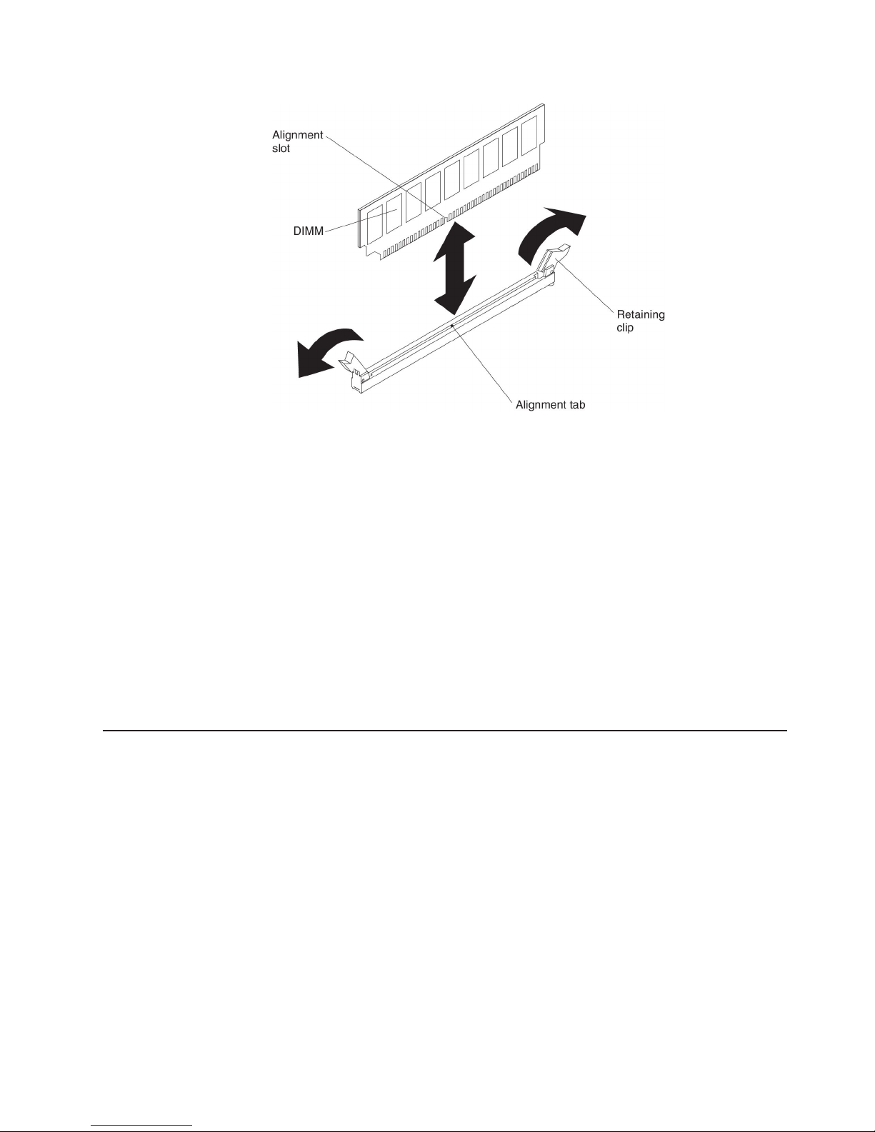
6. Touch the static-protective package that contains the DIMM to any unpainted
metal surface on the outside of the server. Then, remove the DIMM from the
package.
7. Turn the DIMM so that the alignment slot align correctly with the alignment tab.
8. Insert the DIMM into the connector by aligning the edges of the DIMM with the
slots at the ends of the DIMM connector (see “System-board optional devices
connectors” on page 38 for the locations of the DIMM connectors).
9. Firmly press the DIMM straight down into the connector by applying pressure on
both ends of the DIMM simultaneously. The retaining clips snap into the locked
position when the DIMM is firmly seated in the connector.
Note: If there is a gap between the DIMM and the retaining clips, the DIMM
has not been correctly inserted; open the retaining clips, remove the
DIMM, and then reinsert it.
If you have other devices to install or remove, do so now. Otherwise, go to
“Completing the installation” on page 101.
Replacing a PCI riser-card assembly
Note: PCI riser-card brackets must be installed even if you do not install an
adapter.
To replace a PCI riser-card assembly, complete the following steps:
1. Read the safety information that begins on page vii and the “Installation
guidelines” on page 38.
2. Turn off the server and peripheral devices and disconnect the power cords and
all external cables.
Note: When you disconnect the power source from the server, you lose the
ability to view the LEDs because the LEDs are not lit when the power
source is removed. Before you disconnect the power source, make a
note of which LEDs are lit, including the LEDs that are lit on the
operation information panel, on the light path diagnostics panel, and
Chapter 2. Installing optional devices 65
Page 82

LEDs inside the server on the system board; then, see the Problem
Determination and Service Guide for information about how to solve the
problem.
3. Remove the cover (see “Removing the cover” on page 50).
4. Grasp both ends or the handle of the PCI riser-card assembly and lift it out of
the PCI riser-card slot on the system board.
5. If an adapter is installed in the riser-card assembly, disconnect any cables that
are connected to the adapter.
6. Remove the adapter, if one is present, from the PCI riser-card assembly.
7. Set the adapter and the PCI riser-card assembly aside.
8. Install the adapter in the new PCI riser-card assembly (see “Installing an
adapter” on page 67).
9. Set any jumpers or switches on the adapter as directed by the adapter
manufacturer.
10. Remove the PCI filler panel, if one is present, from the rear of the server.
11. Align the PCI riser-card assembly with the PCI riser connector on the system
board; then, press down firmly until the riser-card assembly is seated correctly
in the connector on the system board.
66 IBM System x3550 M4 Type 7914: Installation and User’s Guide
Page 83

If you have other devices to install or remove, do so now. Otherwise, go to
“Completing the installation” on page 101.
Installing an adapter
The following notes describe the types of adapters that the server supports and
other information that you must consider when you install an adapter:
v To confirm that the server supports the adapter that you are installing, see
http://www.ibm.com/systems/info/x86servers/serverproven/compat/us/.
v Locate the documentation that comes with the adapter and follow those
instructions in addition to the instructions in this section.
v The server provides one internal SAS/SATA RAID connector and two PCI slots
on the system board. See “System-board optional devices connectors” on page
38 for the location of the internal SAS/SATA RAID connector and SAS/SATA
RAID riser-card slots. You can replace the IBM ServeRAID SAS/SATA adapter
with an optional IBM ServeRAID SAS/SATA adapter in the slot. For configuration
information, see the ServeRAID documentation at http://www.ibm.com/
supportportal/.
v Do not set the maximum digital video adapter resolution above 1600 x 1200 at
75 Hz for an LCD monitor. This is the highest resolution that is supported for any
add-on video adapter that you install in the server.
v Do not install memory modules more than 128 GB when Quadro 600 is installed.
v Read the following table before installing NAND flash adapters.
Table 10. NAND flash configurations
Description
IBM 365 GB High IOPS MLC
mono adapter
Option
part
number PCI riser 1 PCI riser 2
46C9078 Two microprocessors
installed
Chapter 2. Installing optional devices 67
Two microprocessors
installed
Page 84

Table 10. NAND flash configurations (continued)
Option
part
Description
IBM 785 GB High IOPS MLC
mono adapter
IBM 1.2 TB high IOPS MLC
mono adapter
IBM 2.4 TB high IOPS MLC duo
adapter
number PCI riser 1 PCI riser 2
46C9081 Two microprocessors
installed
90Y4377 Two microprocessors
installed
90Y4397 Two microprocessors
Two microprocessors
installed
Two microprocessors
installed
installed
v Any high-definition video-out connector or stereo connector on any add-on video
adapter is not supported
v The server does not support full-length, full-height PCI adapters or legacy 5V PCI
adapters.
v When you install any PCI adapter, the power cords must be disconnected from
the power source before you remove the PCI Express riser-card assembly and
the PCI-X riser-card assembly. Otherwise, the active power management event
signal will be disabled by the system-board logic, and the Wake on LAN feature
might not work. However, after the server is powered-on locally, the active power
manager active power management event signal will be enabled by the
system-board logic.
v The server provides two PCI riser-card slots on the system board. The following
information describes the PCI riser-card slots and the type of adapters that the
riser cards support:
– If you want to install a PCI Express or PCI-X adapter, you must order the PCI
riser-card option.
– PCI riser slot 1. This slot supports only low-profile adapters.
– PCI riser slot 2. This slot supports full-height, half-length adapters.
The following table lists the supported configurations for the PCI riser-card slots.
Table 11. PCI riser slots supported configurations
PCI
riser-card
slot number Configuration 1
Slot 1 PCI Express 3.0 (x16)
card with a PCI Express
riser card with a
standard bracket
Slot 2 PCI Express 3.0 (x8)
card with a PCI Express
riser card with a
standard bracket
Notes:
1. The instructions in this section apply to any PCI adapter (for example, video
graphics adapters or network adapters).
2. Do not set the maximum digital video adapter resolution above 1600 x 1200 at
75 Hz for an LCD monitor. This is the highest resolution that is supported for
any add-on video adapter that you install in the server.
3. Any high-definition video-out connector or stereo connector on any add-on video
adapter is not supported
68 IBM System x3550 M4 Type 7914: Installation and User’s Guide
Configuration 2 (Two
microprocessors
installed) Configuration 3
PCI Express 3.0 (x16)
card with a PCI Express
riser card with a
standard bracket
PCI Express 3.0 (x16)
card with a PCI Express
riser card with a
standard bracket
PCI Express 3.0 (x16)
card with a PCI Express
riser card with a
standard bracket
PCI-X 64-bit/133 MHz
card with a PCI-X riser
card with a standard
bracket
Page 85

To install an adapter, complete the following steps:
1. Read the safety information that begins on page vii and the “Installation
guidelines” on page 38.
2. Turn off the server and peripheral devices and disconnect the power cords and
all external cables.
3. Remove the server cover (see “Removing the cover” on page 50).
4. Follow the cabling instructions, if any come with the adapter. Route the adapter
cables before you install the adapter.
5. Insert the adapter into the riser-card assembly, aligning the edge connector on
the adapter with the connector on the riser-card assembly. Press the edge of
the connector firmly into the riser-card assembly. Make sure that the adapter
snaps into the riser-card assembly securely.
Attention: When you install an adapter, make sure that the adapter is
correctly seated in the riser-card assembly and that the riser-card assembly is
securely seated in the riser-card connector on the system board before you turn
on the server. An incorrectly seated adapter might cause damage to the system
board, the riser-card assembly, or the adapter.
6. Install the riser-card assembly in the server (see “Replacing a PCI riser-card
assembly” on page 65).
7. Connect the cable to the newly-installed adapter.
Note: You might need to remove the blue latch from PCI riser-card assembly 2
to easily connect the cables.
8. Perform any configuration tasks that are required for the adapter.
Chapter 2. Installing optional devices 69
Page 86

If you have other devices to install or remove, do so now. Otherwise, go to
“Completing the installation” on page 101.
Removing a ServeRAID SAS/SATA controller
The ServeRAID SAS/SATA controller can be installed in the dedicated connector on
the system board or PCI riser-card slots (see “System-board internal connectors” on
page 33 for the location of the connectors).
You can replace the ServeRAID controller with another supported ServeRAID
controller. For a list of supported ServeRAID controllers, see http://www.ibm.com/
servers/eserver/serverproven/compat/us/.
Note: For brevity, in this documentation the ServeRAID SAS/SATA controller is
often referred to as the SAS/SATA adapter or the ServeRAID adapter.
To remove the SAS/SATA adapter from the system board, complete the following
steps:
1. Read the safety information that begins on page vii and the “Installation
guidelines” on page 38.
2. Turn off the server and peripheral devices and disconnect the power cords.
3. Remove the cover (see “Removing the cover” on page 50).
4. Locate the SAS/SATA adapter between PCI slot 1 and microprocessor 1.
5. Disconnect the signal cables and power cables from the connectors on the
SAS/SATA adapter and note their locations.
6. Grasp the end of the SAS/SATA adapter near microprocessor 1 while you slide
the brackets. Slide the retention bracket (near the chassis) toward the chassis;
then, slide the other retention bracket toward the power supplies.
Note: If you have installed the optional ServeRAID adapter memory card,
7. Pull the SAS/SATA adapter horizontally out of the connector on the system
board.
70 IBM System x3550 M4 Type 7914: Installation and User’s Guide
remove it and keep it in future use.
Page 87

Installing a ServeRAID SAS/SATA controller
The adapter can be installed in the dedicated connector on the system board or
PCI riser-card slots (see “System-board internal connectors” on page 33 for the
location of the connectors). To install a SAS/SATA adapter, complete the following
steps:
Depending on the server model, the server comes with a ServeRAID H1110, a
ServeRAID M1115, a ServeRAID M5110, or a ServeRAID 5210 SAS/SATA adapter
installed.
Note: Remove the PCI bracket that come with ServeRAID H1110, ServeRAID
M1115, ServeRAID M5110 SAS/SATA, or a ServeRAID 5210 adapter before
installing a SAS/SATA adapter in the dedicated connector on the system
board.
You can not install ServeRAID H1110 when microprocessor Intel Xeon E5-2637
(FRU part number 49Y8124) is installed.
You can not install ServeRAID M1115 or IBM 6Gb performance optimized HBA
when Quadro 2000 is installed.
You can replace the ServeRAID controller with another supported ServeRAID
controller. For a list of supported ServeRAID controllers, see http://www.ibm.com/
servers/eserver/serverproven/compat/us/.
Note: For brevity, in this documentation the ServeRAID SAS/SATA controller is
often referred to as the SAS/SATA adapter or the ServeRAID adapter.
1. Read the safety information that begins on page vii and “Installation guidelines”
on page 38.
2. Turn off the server and peripheral devices and disconnect the power cords.
3. Remove the cover (see “Removing the cover” on page 50).
4. Remove PCI riser-card assembly 1 if necessary (see “Replacing a PCI
riser-card assembly” on page 65).
5. If you are installing a new or replacement SAS/SATA adapter, touch the
static-protective package that contains the new SAS/SATA adapter to any
unpainted metal surface on the server. Then, remove the new SAS/SATA
adapter from the package.
6. Align the SAS/SATA adapter so that the keys align correctly with the connector
on the system board.
7. Insert the SAS/SATA adapter in the dedicated connector on the system board or
PCI riser-card slots.
Attention: Incomplete insertion might cause damage to the server or the
adapter.
a. Insert the SAS/SATA adapter into the RAID connector on the system board
until it is firmly seated. The retention brackets secure the SAS/SATA adapter
in place when the adapter is firmly seated into the connector.
Note: Remove the PCI bracket that come with ServeRAID H1110,
ServeRAID M1115, or ServeRAID M5110 SAS/SATA adapter before
installing a SAS/SATA adapter in the dedicated connector on the
system board.
Chapter 2. Installing optional devices 71
Page 88

72 IBM System x3550 M4 Type 7914: Installation and User’s Guide
Page 89
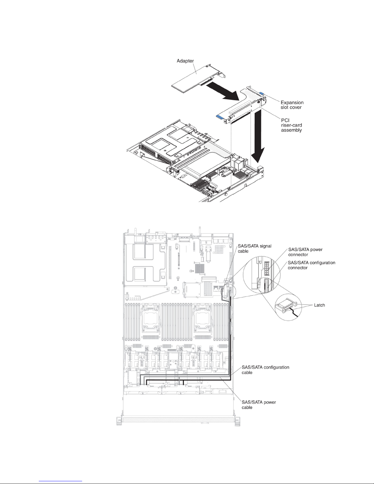
b. Insert the SAS/SATA adapter into the PCI riser cards. (see “Installing an
adapter” on page 67).
8. Route the backplane signal cables (see “Internal cable routing and connectors”
on page 41).
9. Connect the signal cables to the SAS/SATA adapter:
Chapter 2. Installing optional devices 73
Page 90
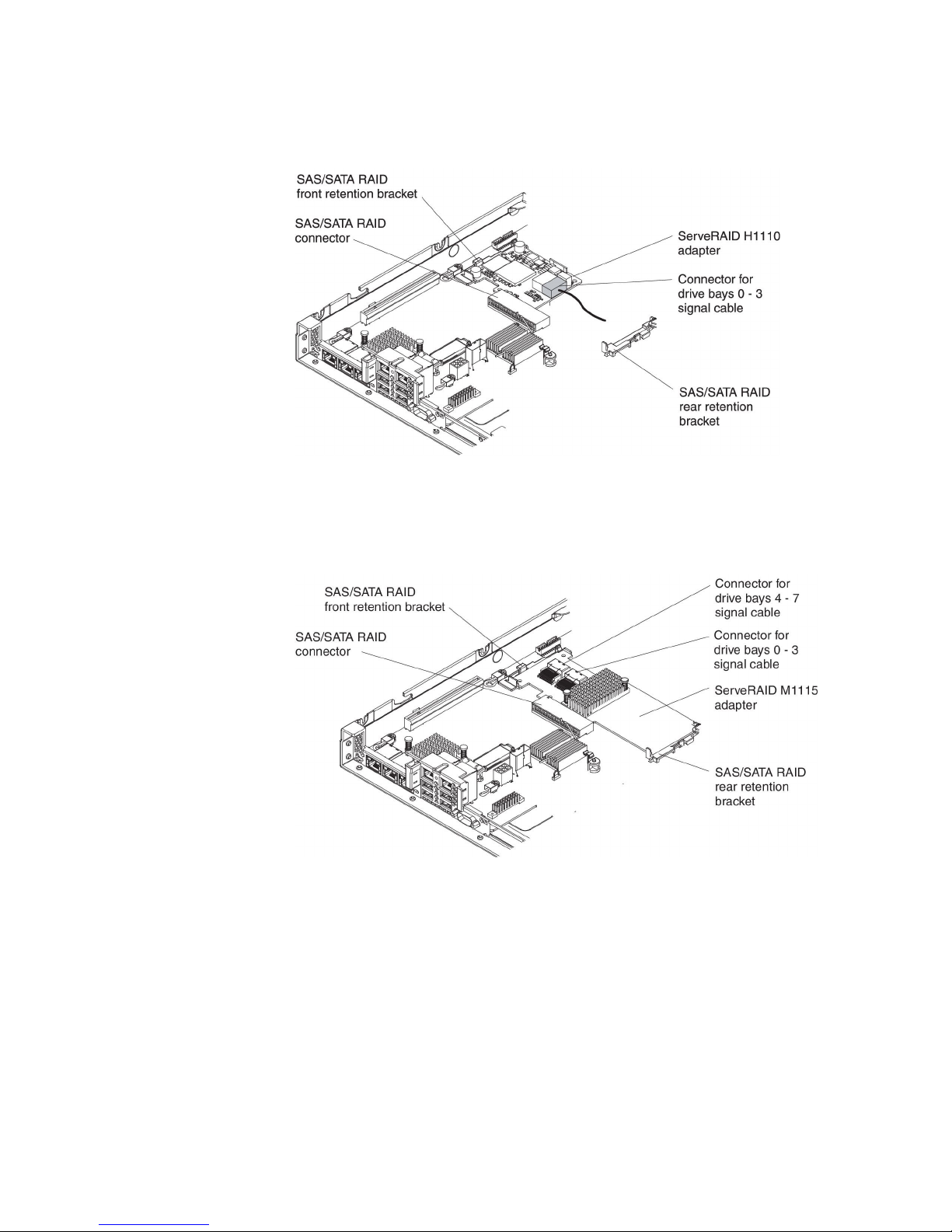
v ServeRAID H1110 adapter: Take the signal cable that is attached to the
drive backplane for drive bays 0 through 3 and connect it to the SAS/SATA
connector on the ServeRAID adapter.
v ServeRAID M1115 adpater: Take the signal cable that is attached to the
drive backplane for drive bays 4 through 7 and connect it to the ServeRAID
adapter connector for drive bays 4 through 7 (port 1). Connect the other
signal cable that is attached to the drive backplane for drive bays 0 through 3
and connect it to the other connector (port 0) on the adapter.
v ServeRAID M5110 adapter: Take the signal cable that is attached to the
drive backplane for drive bays 4 through 7 and connect it to the ServeRAID
adapter connector for drive bays 4 through 7 (port 1). Connect the other
signal cable that is attached to the drive backplane for drive bays 0 through 3
and connect it to the other connector (port 0) on the adapter.
74 IBM System x3550 M4 Type 7914: Installation and User’s Guide
Page 91

Note: When you restart the server, you are prompted to import the existing
RAID configuration to the new ServeRAID adapter.
If you have other devices to install or remove, do so now. Otherwise, go to
“Completing the installation” on page 101.
Installing an optional ServeRAID adapter memory module
To install an optional ServeRAID adapter memory module, complete the following
steps:
1. Read the safety information that begins on page vii and “Installation guidelines”
on page 38.
2. Turn off the server and peripheral devices and disconnect the power cords.
3. Remove the cover (see “Removing the cover” on page 50).
4. Align the memory module with the connector on the ServeRAID adapter and
push it into the connector until it is firmly seated.
If you have other devices to install or remove, do so now. Otherwise, go to
“Completing the installation” on page 101.
Installing the DVD drive cable
To install the DVD drive cable, complete the following steps:
Chapter 2. Installing optional devices 75
Page 92

1. Read the safety information that begins on page vii and “Installation guidelines”
on page 38.
2. Turn off the server and peripheral devices and disconnect the power cords and
all external cables.
3. Remove the cover (see “Removing the cover” on page 50).
4. Remove the air baffle (see “Removing the air baffle” on page 51).
5. Align the cable connector with the connector on the rear of the DVD drive cage.
Press the cable connector into the optical drive cage connector and slide it to
the left until it is firmly seated.
The following illustration shows cable routing for the DVD cable:
Attention: Follow the optical drive cable routing as the illustration shows.
Make sure that the cable is not pinched and does not cover any connectors or
obstruct any components on the system board.
76 IBM System x3550 M4 Type 7914: Installation and User’s Guide
Page 93
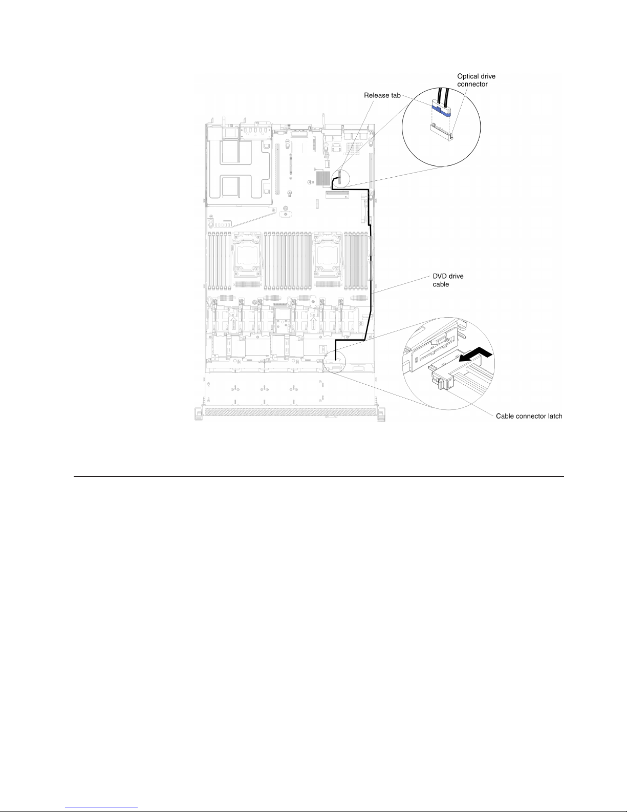
If you have other devices to install or remove, do so now. Otherwise, go to
“Completing the installation” on page 101.
Installing a SAS/SATA 4 Pac HDD option
You can install an IBM System x3550 M4 hot-swap SAS/SATA 4 Pac HDD option to
add four additional 2.5-inch hot-swap hard disk drives in the server. See
http://www.ibm.com/servers/eserver/serverproven/compat/us/ for a list of supported
optional devices. To order a SAS/SATA 4 Pac HDD option, contact your IBM
marketing representative or authorized reseller.
The SAS/SATA 4 Pac HDD option kit contains the following components:
v One 2.5-inch hot-swap hard disk drive backplane (with bracket)
v Four drive bay filler panels
v One SAS signal cable
Note: The 4 pac HDD option including structural parts and Tier 1 parts.
To install a SAS/SATA 4 Pac HDD option, complete the following steps:
1. Read the safety information that begins on page vii and “Installation guidelines”
on page 38.
2. Turn off the server and peripheral devices and disconnect the power cords and
all external cables.
3. Remove the cover (see “Removing the cover” on page 50).
Chapter 2. Installing optional devices 77
Page 94
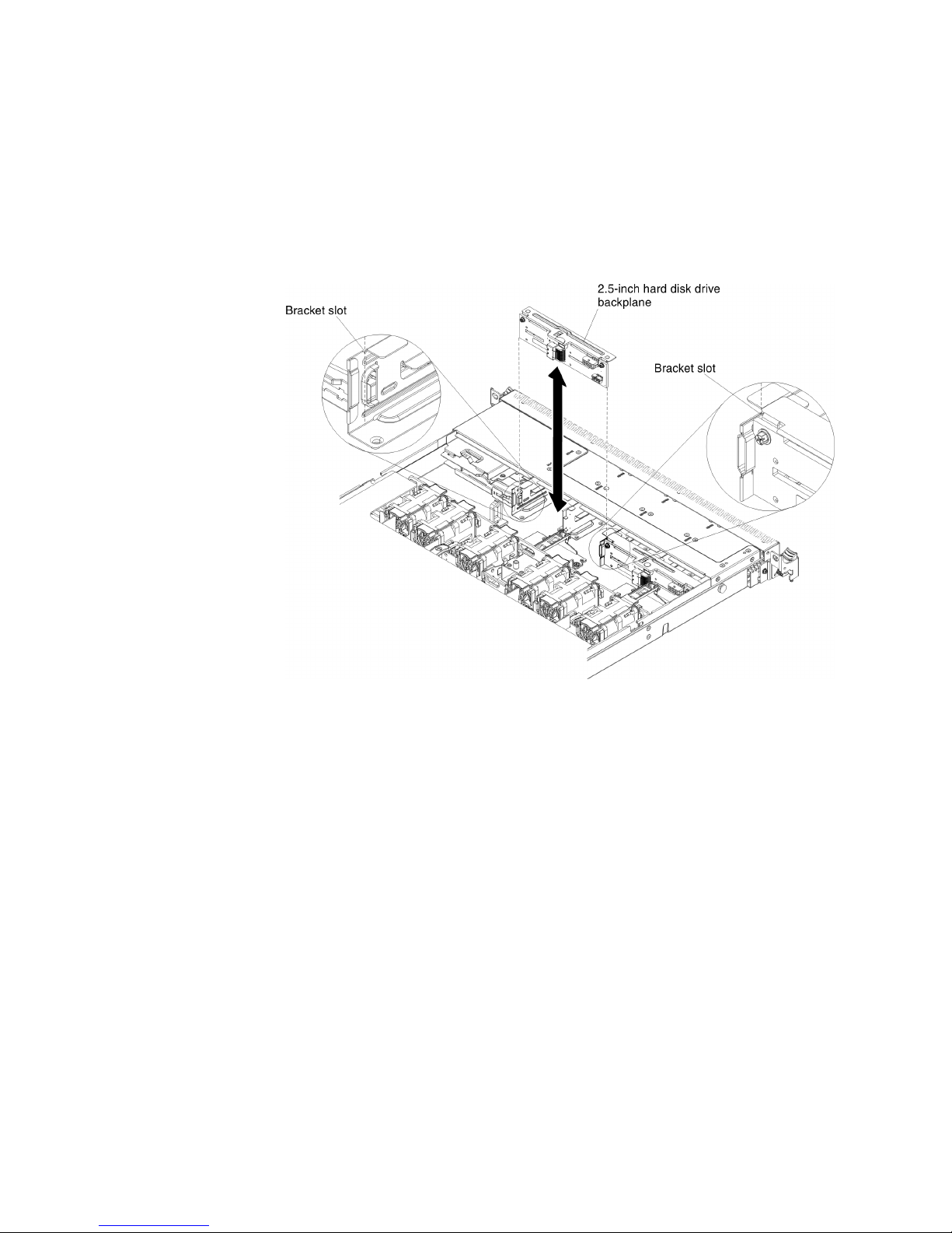
4. Align the sides of the hard disk drive backplane with the slots on the
backplane bracket.
5. Insert the hard disk drive backplane into the slots on the backplane bracket
and push the hard disk drive backplane down until the backplane is fully
seated.
Note: You can reconnect the cables to the hard disk drive backplane before
installing the backplane onto the brackets or you can connect the
cables after you install the backplane, if that is easier for you.
6. Connect the cables to the hard disk drive backplane.
7. Connect the signal, power and configuration cables to the system board. Route
the signal cable from the drive backplane along the chassis and connect it to
the SAS/SATA controller connectors (see step 9 on page 73). Then, route the
power cable and the configuration cable from the drive backplane along the
chassis and connect it to the SAS/SATA power connector and SAS/SATA
configuration connector, as shown in the following illustration.
78 IBM System x3550 M4 Type 7914: Installation and User’s Guide
Page 95
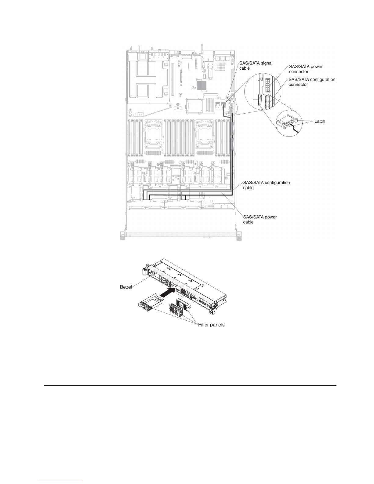
8. Pull existing filler panels out of the server. Keep them in a safe place.
9. Install the hard disk drives.
10. Install the filler panels that come with the SAS/SATA 4 Pac HDD option into
empty drive bays.
If you have other devices to install or remove, do so now. Otherwise, go to
“Completing the installation” on page 101.
Installing a second microprocessor and heat sink
The following notes describe the type of microprocessor that the server supports
and other information that you must consider when you install a microprocessor and
heat sink:
v Microprocessors are to be installed only by trained technicians.
Important: Always use the microprocessor installation tool to install a
microprocessor. Failing to use the microprocessor installation tool may damage
Chapter 2. Installing optional devices 79
Page 96

the microprocessor sockets on the system board. Any damage to the
microprocessor sockets may require replacing the system board.
™
v The server supports up to two Intel Xeon
E5-2600 series multi-core
microprocessors, which are designed for the LGA 2011 socket. See
http://www.ibm.com/servers/eserver/serverproven/compat/us/ for a list of
supported microprocessors.
v Do not mix dual-core, quad-core, and six-core microprocessors in the same
server.
v The first microprocessor must always be installed in microprocessor socket 1 on
the system board.
v When one microprocessor is installed, the air baffle must be installed to provide
proper system cooling.
v Do not remove the first microprocessor from the system board when you install
the second microprocessor.
v When you install the second microprocessor, you must also install additional
memory, the fourth and sixth fans. See “Installing a memory module” on page 59
for details about the installation sequence.
v To ensure proper server operation when you install an additional microprocessor,
use microprocessors that have the same QuickPath Interconnect (QPI) link
speed, integrated memory controller frequency, core frequency, power segment,
internal cache size, and type.
v Mixing microprocessors of different stepping levels within the same server model
is supported.
v When mixing microprocessors with different stepping levels within the same
server model, you do not have to install the microprocessor with lowest stepping
level and features in microprocessor socket 1.
v Both microprocessor voltage regulator modules are integrated on the system
board.
v Read the documentation that comes with the microprocessor to determine
whether you have to update the server firmware. To download the latest level of
server firmware and other code updates for the server, go to
http://www.ibm.com/support/fixcentral/.
v The microprocessor speeds are automatically set for this server; therefore, you
do not have to set any microprocessor frequency-selection jumpers or switches.
v If the thermal-grease protective cover (for example, a plastic cap or tape liner) is
removed from the heat sink, do not touch the thermal grease on the bottom of
the heat sink or set down the heat sink. For details, see the information about
thermal grease in the Problem Determination and Service Guide.
Note: Removing the heat sink from the microprocessor destroys the even
distribution of the thermal grease and requires replacing the thermal
grease.
v To order an additional optional microprocessor, contact your IBM marketing
representative or authorized reseller.
To install an additional microprocessor and heat sink, complete the following steps:
1. Read the safety information that begins on page vii and “Installation guidelines”
on page 38.
2. Turn off the server and peripheral devices and disconnect the power cords and
all external cables (see “Turning off the server” on page 28).
80 IBM System x3550 M4 Type 7914: Installation and User’s Guide
Page 97

Attention: When you handle static-sensitive devices, take precautions to
avoid damage from static electricity. For details about handling these devices,
see “Handling static-sensitive devices” on page 40.
3. Remove the cover (see “Removing the cover” on page 50).
4. Remove the air baffle (see “Removing the air baffle” on page 51).
5. Locate microprocessor socket 2 on the system board (see “System-board
internal connectors” on page 33).
6. Rotate the heat sink retention module release lever to the open position.
7. Open the microprocessor socket release levers and retainer:
a. Identify which release lever is labeled as the first release lever to open and
open it.
b. Open the second release lever on the microprocessor socket.
c. Open the microprocessor retainer.
Attention: Do not touch the connectors on the microprocessor and the
microprocessor socket.
8. Install the microprocessor on the microprocessor socket:
a. Touch the static-protective package that contains the new microprocessor
to any unpainted on the chassis or any unpainted metal surface on any
other grounded rack component; then, carefully remove the microprocessor
from the package.
b. Release the sides of the cover and remove the cover from the installation
tool. The microprocessor is preinstalled on the installation tool.
Chapter 2. Installing optional devices 81
Page 98

Note: Do not touch the microprocessor contacts. Contaminants on the
microprocessor contacts, such as oil from your skin, can cause
connection failures between the contacts and the socket.
c. Align the installation tool with the microprocessor socket. The installation
tool rests flush on the socket only if properly aligned.
d. Twist the handle on the microprocessor tool counterclockwise to insert the
microprocessor into the socket. The microprocessor is keyed to ensure that
the microprocessor is installed correctly. The microprocessor rests flush on
the socket only if properly installed.
Attention:
v Do not press the microprocessor into the socket.
82 IBM System x3550 M4 Type 7914: Installation and User’s Guide
Page 99

v Make sure that the microprocessor is oriented and aligned correctly in
the socket before you try to close the microprocessor retainer.
v Do not touch the thermal material on the bottom of the heat sink or on
top of the microprocessor. Touching the thermal material will
contaminate it.
9. Remove the microprocessor socket dust cover, tape, or label from the surface
of the microprocessor socket, if one is present. Store the socket cover in a
safe place.
Attention: When you handle static-sensitive devices, take precautions to
avoid damage from static electricity. For details about handling these devices,
see “Handling static-sensitive devices” on page 40.
10. Close the microprocessor socket release levers and retainer:
a. Close the microprocessor retainer on the microprocessor socket.
b. Identify which release lever is labeled as the first release lever to close and
close it.
c. Close the second release lever on the microprocessor socket.
11. Install the heat sink:
Chapter 2. Installing optional devices 83
Page 100
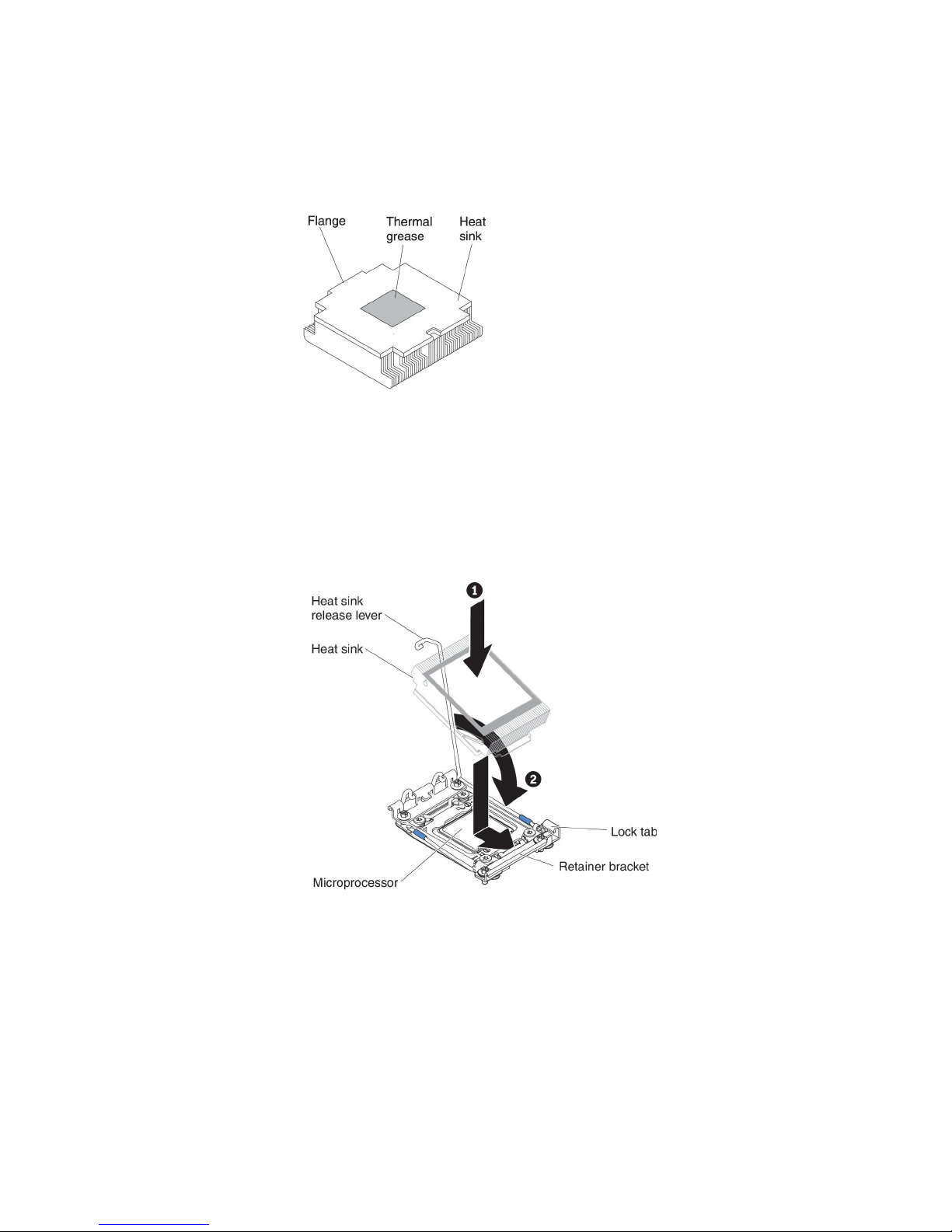
Attention:
v Do not set down the heat sink after you remove the plastic cover.
v Do not touch the thermal grease on the bottom of the heat sink after you
remove the plastic cover. Touching the thermal grease will contaminate it.
See “Thermal grease” for more information.
a. Remove the plastic protective cover from the bottom of the heat sink.
b. Position the heat sink over the microprocessor. The heat sink is keyed to
assist with proper alignment.
c. Align and place the heat sink on top of the microprocessor in the retention
bracket, thermal material side down.
d. Press firmly on the heat sink.
e. Rotate the heat sink retention module release lever to the closed position
and hook it underneath the lock tab.
12. If you installed the second microprocessor, install the fourth and sixth fans (see
“Installing a hot-swap fan assembly” on page 93).
If you have other devices to install or remove, do so now. Otherwise, go to
“Completing the installation” on page 101.
Thermal grease
The thermal grease must be replaced whenever the heat sink has been removed
from the top of the microprocessor and is going to be reused or when debris is
found in the grease.
84 IBM System x3550 M4 Type 7914: Installation and User’s Guide
 Loading...