

Page 1
Install options:
• Drives
®
• Microprocessors
• Adapters
• Memory
xSeries 330
Installation Guide
Welcome. . .
Thank you for buying an
IBM xSeries server.
This server
contains information for setting
up and configuring your server.
For detailed information
about your server, view the
User's Reference
Installation Guide
on the
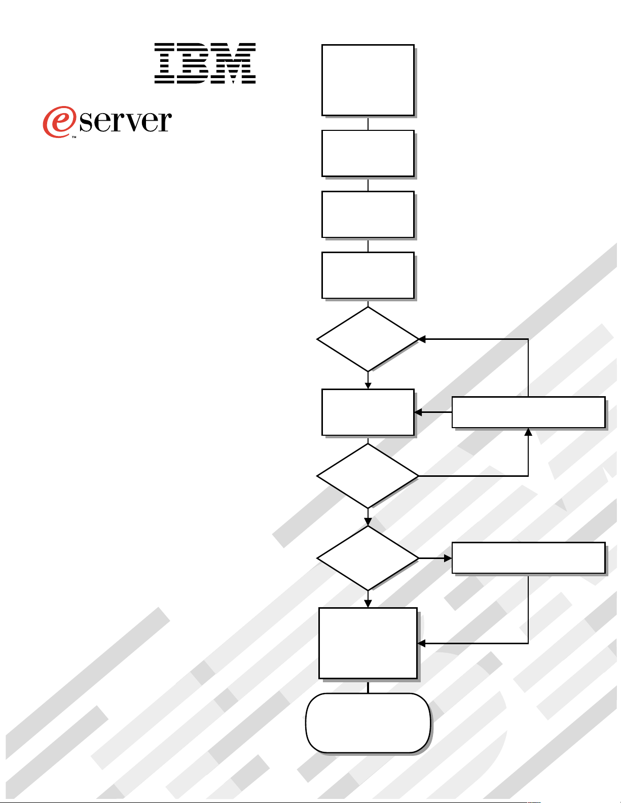
Install the server in
the rack, if required
Cable the server
and options
Start the server
Did the server
start correctly?
Yes
Use ServerGuide™
to setup and
configure hardware
No
Go to the Server Support
flow chart
Documentation CD.
You can also find the most
current information about your
server on the IBM Web site at:
http://www.ibm.com/pc/support
Did configuration
complete?
Yes
Use
ServerGuide to
install operating
system?
Yes
Use ServerGuide to
install applications,
such as IBM systems
management software
and IBM ServeRAID
programs
System is ready to use.
Go to the Server Support
flow chart to register
and profile your server.
No
No
Go to the Web for Instructions,
http://www.ibm.com/pc/support
Page 2
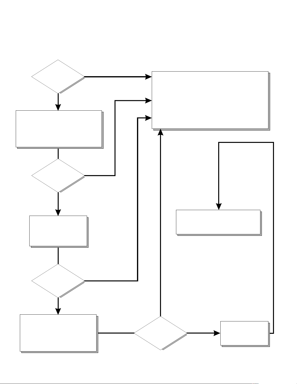
Server Support
Server working
properly?
Yes
No
Check all cables for loose connections
and verify that all optional devices you
installed are on the ServerProven list.
You can view the ServerProven list at:
http://www.ibm.com/pc/compat
Problem
solved?
Yes
No
Register and profile your server
After you register and profile, you will be able to:
• Diagnose problems using the IBM Online Assistant
• Participate in the IBM discussion forum
• Receive e-mail notifications of technical updates
related to your profiled products
Register at:
Profile at:
http://www.ibm.com/pc/register
http://www.ibm.com/pc/support
Use the troubleshooting
information provided with
your server to determine
the cause of the problem
and the action to take.
Problem
solved?
Yes
No
Flash the latest levels of BIOS,
service processor, diagnostics,
and RAID code.
You can download this code at:
http://www.ibm.com/pc/support
Yes
Problem
solved?
You can view a list of
IBM Help Center phone numbers at:
http://www.ibm.com/pc/support
No
Phone an
IBM Help Center
Page 3

IBM® xSeries 330
Installation Guide
IBM
SC06-P455-80
Page 4

Note
Before using this information and the product it supports, be sure to read the general information in
"Appendix A. Product warranties and notices," page 33.
First Edition (October 2000)
© Copyright International Business Machines Corporation 2000. All rights reserved.
US Government Use rs Rest ric t ed R igh ts – Use, duplication or discl osu re restricted b y GS A AD P Sc h e dule C ont ra ct wit h
IBM Corp.
Page 5

Contents
Safety . . . . . . . . . . . . . . . . . . . . . . . . . . . . . v
Chapter 1.Introduction . . . . . . . . . . . . . . . . 1
Features and specifications . . . . . . . . . . . . . . . . . . . . . . . . 2
Notices used in this book. . . . . . . . . . . . . . . . . . . . . . . . . . 3
Handling static sensitive devices . . . . . . . . . . . . . . . . . . . 4
Major components of the xSeries 330 server. . . . . . . . . . 5
Chapter 2.Installing Options. . . . . . . . . . . . 7
Working with adapters. . . . . . . . . . . . . . . . . . . . . . . . . . . . 7
Adapter considerations. . . . . . . . . . . . . . . . . . . . . . . . . 8
Installing an adapter . . . . . . . . . . . . . . . . . . . . . . . . . . . 8
Working with memory . . . . . . . . . . . . . . . . . . . . . . . . . . . 10
Memory considerations . . . . . . . . . . . . . . . . . . . . . . . 10
Installing memory modules. . . . . . . . . . . . . . . . . . . . 11
Working with hard disk drives. . . . . . . . . . . . . . . . . . . . 13
Hard disk drive considerations . . . . . . . . . . . . . . . . . 13
Installing a hard disk drive. . . . . . . . . . . . . . . . . . . . . 13
Working with microprocessors . . . . . . . . . . . . . . . . . . . . 14
Microprocessor considerations . . . . . . . . . . . . . . . . . 15
Installing a microprocessor. . . . . . . . . . . . . . . . . . . . . 15
Working with cables . . . . . . . . . . . . . . . . . . . . . . . . . . . . . 17
Cabling the RS-485 ports. . . . . . . . . . . . . . . . . . . . . . . 17
Connecting the ASM bus. . . . . . . . . . . . . . . . . . . . 18
Connecting the servers with a C2T chain. . . . . . . . . 19
Testing the C2T chain. . . . . . . . . . . . . . . . . . . . . . . 21
Cable management . . . . . . . . . . . . . . . . . . . . . . . . . . . 21
Chapter 3.Server power , controls and
indicators . . . . . . . . . . . . . . . . . . . . . . . . . 23
Turning on the server . . . . . . . . . . . . . . . . . . . . . . . . . . . . 23
Turning off the server . . . . . . . . . . . . . . . . . . . . . . . . . . . 24
Stand-by mode. . . . . . . . . . . . . . . . . . . . . . . . . . . . . . . 24
Server controls and indicators. . . . . . . . . . . . . . . . . . . . . 25
Front view. . . . . . . . . . . . . . . . . . . . . . . . . . . . . . . . . . . 25
Rear view. . . . . . . . . . . . . . . . . . . . . . . . . . . . . . . . . . . . 26
System management solutions . . . . . . . . . . . . . . . . . . . . 28
Chapter 5.Solving problems. . . . . . . . . . . 29
Diagnostic tools overview . . . . . . . . . . . . . . . . . . . . . . . . 29
POST beep code descriptions. . . . . . . . . . . . . . . . . . . . . . 30
POST error messages. . . . . . . . . . . . . . . . . . . . . . . . . . . . . 30
ServerGuide startup problems . . . . . . . . . . . . . . . . . . . . 32
Troubleshooting charts . . . . . . . . . . . . . . . . . . . . . . . . . . . 33
Appendix A. Product warranties and
notices . . . . . . . . . . . . . . . . . . . . . . . . . . . 41
Warranty Statements. . . . . . . . . . . . . . . . . . . . . . . . . . . . . 41
IBM Statement of Limited Wa rranty for United States,
Puerto Rico, and Canada (Part 1 - General Terms) . 41
IBM Statement of Warranty Worldwide except
Canada, Puerto Rico, Turkey, United States (Part 1 –
General Terms) . . . . . . . . . . . . . . . . . . . . . . . . . . . . . . . 44
Part 2 - Worldwide Country-Unique Terms. . . . . . . 46
Notices. . . . . . . . . . . . . . . . . . . . . . . . . . . . . . . . . . . . . . . . . 50
Edition Notice. . . . . . . . . . . . . . . . . . . . . . . . . . . . . . . . 50
Processing date data . . . . . . . . . . . . . . . . . . . . . . . . . . 51
Trademarks . . . . . . . . . . . . . . . . . . . . . . . . . . . . . . . . . . 51
Important notes . . . . . . . . . . . . . . . . . . . . . . . . . . . . . . 52
Electronic emission notices . . . . . . . . . . . . . . . . . . . . . . . 52
Federal Communications Commission (FCC)
Statement. . . . . . . . . . . . . . . . . . . . . . . . . . . . . . . . . . . . 52
Industry Canada Class A emission compliance
statement . . . . . . . . . . . . . . . . . . . . . . . . . . . . . . . . . . . . 53
Australia and New Zealand Class A statement. . . . 53
United Kingdom telecommunications safety
requirement. . . . . . . . . . . . . . . . . . . . . . . . . . . . . . . . . . 53
European Union EMC Directive conformance
statement . . . . . . . . . . . . . . . . . . . . . . . . . . . . . . . . . . . . 53
Taiwan electrical emission statement . . . . . . . . . . . . 54
Japanese Voluntary Control Council for Interference
(VCCI) statement . . . . . . . . . . . . . . . . . . . . . . . . . . . . . 54
Power cords . . . . . . . . . . . . . . . . . . . . . . . . . . . . . . . . . . . . 54
Chapter 4.Configuring your server . . . . . 27
Using the ServerGuide CDs. . . . . . . . . . . . . . . . . . . . . . . 28
© Copyright IBM Corp. 2000 iii
Index . . . . . . . . . . . . . . . . . . . . . . . . . . . . . . 57
Page 6

iv IBM® xSeries 330 In st all at ion Guide
Page 7
Safety
Before installing this product, read the Safety Information book.
Antes de instalar este produto, leia o Manual de Informações sobre Segurança.
Pred instalací tohoto produktu si prectete prírucku bezpecnostních instrukcí.
Læs hæftet med sikkerhedsforskrifter, før du installerer dette produkt.
Lue Safety Information -kirjanen, ennen kuin asennat tämän tuotteen.
Avant de procéder à l'installation de ce produit, lisez le manuel Safety Information.
Vor Beginn der Installation die Broschüre mit Sicherheitshinweisen lesen.
Przed zainstalowaniem tego produktu należy przeczytać broszurę Informacje Dotyczące
Bezpieczeństwa.
Prima di installare questo prodotto, leggere l'opuscolo contenente le informazioni
sulla sicurezza.
© Copyright IBM Corp. 2000 v
Page 8

Lees voordat u dit product installeert eerst het boekje met veiligheidsvoorschriften.
Les heftet om sikkerhetsinformasjon (Safety Information) før du installerer dette
produktet.
Antes de instalar este produto, leia o folheto Informações sobre Segurança.
Перед установкой продукта прочтите брошюру по технике безопасности
(Safety Information).
Pred inštaláciou tohto produktu si pre ítajte Informa nú brožúrku o bezpe nosti.
Preden namestite ta izdelek, preberite knjižico Varnostne informacije.
Antes de instalar este producto, lea la Información de Seguridad.
Läs säkerhetsinformationen innan du installerar den här produkten.
Installálás el tt olvassa el a Biztonsági el írások kézikönyvét !
vi IBM® xSeries 330: Ins tallation Guide
Page 9
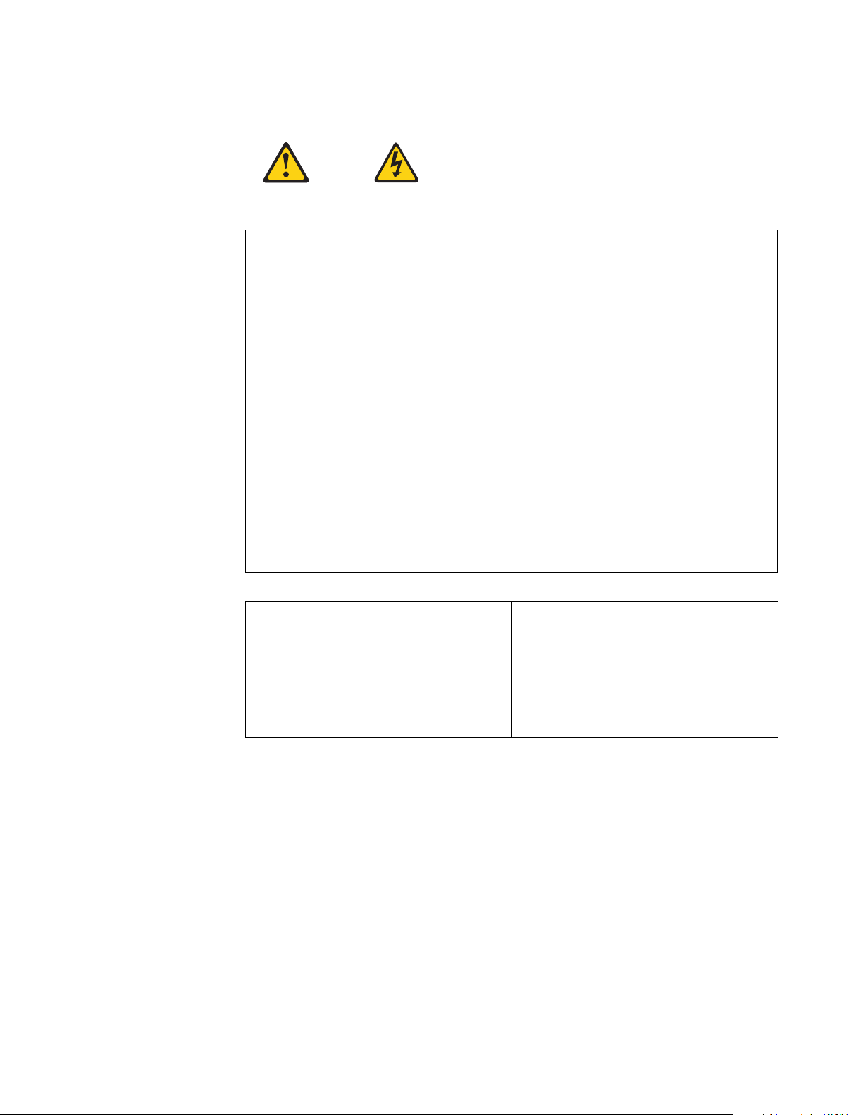
Statement 1
DANGER
Electrical current from power, telephone, and commu nica tion ca ble s is haz ardo us.
To avoid a shock hazard:
• Do not connect or disconnect any cables or perform installation,
maintenance, or reconfiguration of this product during an electrical storm.
• Connect all power cords to a properly wired and grounded electrical outlet.
• Connect to properly wired outlets any equipment that will be attached to this
product.
• When possible, use one hand only to connect or disconnect signal cables.
• Never turn on any equipment when there is evidence of fire, water, or
structural damage.
• Disconnect the attached power cords, telecommunications systems,
networks, and mo dem s bef or e you o pen the device cove rs, unl ess i nstr uc ted
otherwise in the installation and configuration procedures.
• Connect and disconnect cables as described in the following table when
installing, moving, or opening covers on this product or attached devices.
To connect:
1. Turn everything OFF.
2. First, attach all cables to devices.
3. Attach signal cables to connectors.
4. Attach power cords to outlet.
5. Turn device ON.
To disconnect:
1. Turn everything OFF.
2. First, remove power cords from outlet.
3. Remove signal cables from connectors.
4. Remove all cables from devices.
vii
Page 10
Statement 2
CAUTION:
When replacing the lithium battery, use only IBM Part Number 33F8354 or an
equivalent type battery recommended by the manufacturer. If your system has a
module containing a lithium battery, replace it only with the same module type
made by the same manufacturer. The battery contains lithium and can explode if
not properly used, handled, or disposed of.
Do not:
• Throw or immerse into water.
• Heat to more than 100 C (212 F)
• Repair or disassemble
Dispose of the battery as required by local ordinances or regulations.
Statement 3
CAUTION:
When laser products (such as CD-ROMs, DVD drives, fiber optic devices, or
transmitters) are installed, note the following:
• Do not remove the covers. Removing the covers of the laser product could
result in exposure to hazardous laser radiati on. There ar e no serviceable parts
inside the device.
• Use of controls or adjustments or performance of procedures other than those
specified herein might result in hazardous radiation exposure.
DANGER
Some laser products co ntain an em bedded Class 3A or Cl ass 3B laser diode. N ote
the following. Laser radiation when open. Do not stare into the beam, do not view
directly with optical instruments, and avoid direct exposure to the beam.
viii IBM® xSeries 330: Installation Guide
Page 11
Class 1 Laser Product
1
2
Laser Klasse 1
Laser Klass 1
Luokan 1 Laserlaite
Appareil A Laser de Classe 1
`
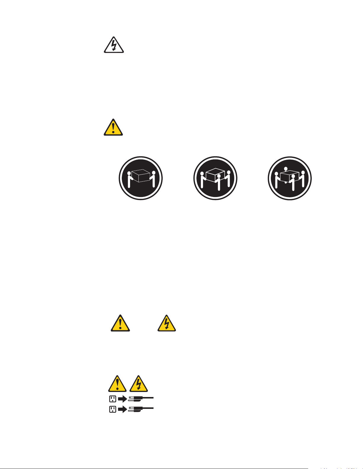
Statement 4
≥18 kg (37 lbs)
≥32 kg (70.5 lbs)
≥55 kg (121.2 lbs)
CAUTION:
Use safe practices when lifting.
Statement 5
CAUTION:
The power control button on the device and the power switch on the p ower supply
do not turn off the electrical current supplied to the device. The device also might
have more than one power cord. To remove all electrical current from the device,
ensure that all power cords are disconnected from the power source.
ix
Page 12
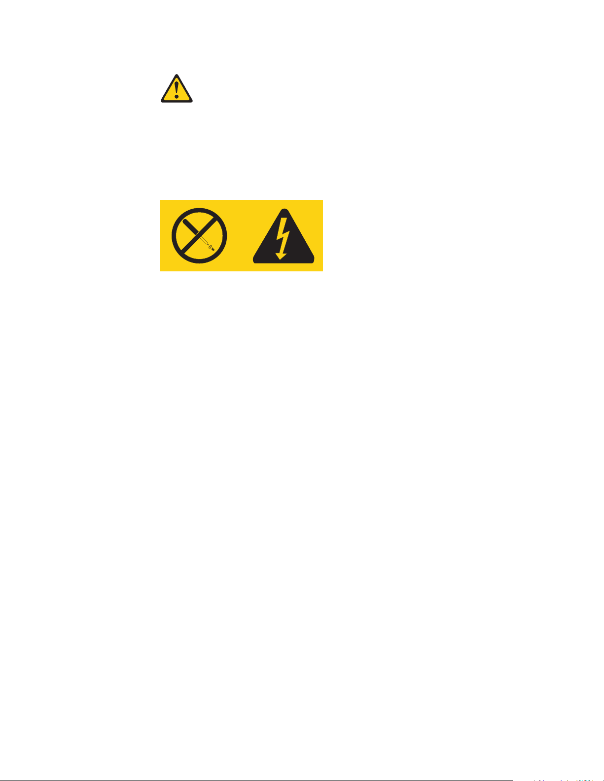
Statement 8
CAUTION:
Never remove the cover on a power supply or any part that has the following label
attached.
Hazardous voltage, current, and energy levels are present inside any component
that has this label attached. There are no serviceable parts inside these
components. If you suspect a problem with one of these parts, contact a service
technician.
Handling static devices
This is a test of the emergency
x IBM® xSeries 330: Inst allation Guide
Page 13
Chapter 1. Introduction
Thank you for purchasing an IBM® xSeries 330 server. This Installation Guide
provides the information that is needed to:
• Set up and cable your server
• Start and configure your server
• Install your network operating system (NOS)
Packaged with the Installation Guide are software CDs that help you to configure
hardware, install device drivers, and install the network operating system.
Also included is an IBM xSeries Documentation CD, which provides detailed
information about your server.
Your xSeries 330 server comes with a three-year limited warranty and IBM Server
Start Up Support. If you have access to the World Wide Web, you can obtain up-todate information about your xSeries 330 model and other IBM server products at
http://www.ibm.com/eserver/xseries.
Record your product information in this table.
Product name _________________________________________________
Machine type _________________________________________________
Model number _________________________________________________
Serial number _________________________________________________
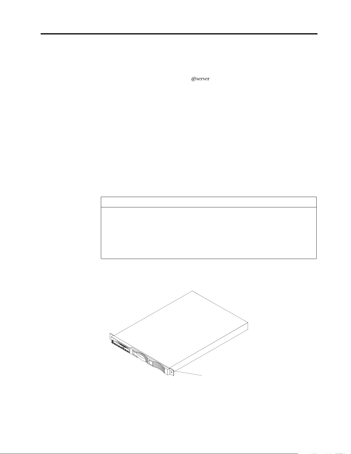
The machine type, and serial number are located on the ID label located on the top of
the server just behind the bezel on the right.
ID label
© Copyright IBM Corp. 2000 1
Page 14

Features and specifications
The following table provides a summary of the features and specifications for your
xSeries 330 server.
Microprocessor:
®
•Intel
Pentium® III
microprocessor with MMX™
technology and SIMD
extensions
• 256 KB Level-2 cache
• Supports up to two
microprocessors
Memory:
• Standard: 256 MB
• Maximum: 4 GB
• Type: 133 MHz, ECC,
SDRAM, Registered DIMMs
• Slots: 4 dual inline
Drives standard:
• Diskette: 1.44 MB
• CD-ROM: 24X IDE
Expansion bays:
• Two 3.5-inch slim high bays
for LVD SCSI hard disk
drives
PCI expansion slots:
• Two 33 MHz/64-bit
Power supply:
One 200 watt (115-230 Vac)
Video:
• S3 video controller
(integrated on system board)
• Compatible with SVGA
• 8 MB SDRAM video memory
Size
• Height 43.69 mm (1.72")
• D epth: 653.29 mm (25. 72")
• Width: 439.93 mm (17.32")
• Weight: approximately 12.7
kg (28lb) when fully
configured
Integrated functions:
• Advanced System
Management processor
• One Ultra160 SCSI controller
• Two 10BASE-T/100BASE -TX
Intel Ethernet controllers
• Two Universal S erial Bus
(USB) ports
• Two RS-485 Advanced System
Management processor ports
(one In, one Out)
• One serial port
• Two console ports (one In, one
Out)
Acoustical noise emissions:
• Sound power, idling: 6.1 bel
maximum
• Sound power, operating: 6.2
bel maxi mu m
Environment:
• Air temperature:
°
°
to 35
— Server on: 10
°
F). Altitude: 0 to
to 95.0
C (50.0°
914 m (2998.7 ft.)
— Server on: 10° to 32° C
°
to 89.6° F). Altitude:
(50.0
914 m (2998.7 ft.) to 2133 m
(6998.0 ft.)
°
— Server off: 10
(50.0
°
to 109.4° F).
to 43° C
Maximum altitude: 2133 m
(6998.0 ft.)
• Humidity:
— Server on: 8% to 80%
— Server off: 8% to 80%
Heat output:
Approximate heat output in British
Thermal Units (BTU) per hour
• Min imum configuration: 273
BTU
(80 watts)
• M aximum configuration: 751
BTU
(220 watts)
Electrical input:
• Sine-wave input (50-60 Hz)
required
• Input voltage low range:
— Minimum: 100 V ac
— Maximum : 12 7 V ac
• Input voltage high range:
— Minimum: 200 V ac
— Maximum : 24 0 V ac
• Input kilovolt-amperes (kVA)
approximately:
— Minimum: 0.08 kVA
— Maximum : 0. 22 kVA
Table 1. Features and Specifications
2 IBM® xSeries 330: Installation Guide
Page 15

Notices used in this book
This information product contains notices that relate to a specific topic. The Caution
and Danger notices also appear in the multilingual safety information provided with
your product. Each safety notice is number ed fo r ea sy reference to the corresponding
notices in the safety information on the documentation CD.
The following is a list of the notices and their definitions as used in this book:
• Notes: These notices provide important tips, guidance, or advice.
•Impor tant: These notices provide informatio n or advice that might help you
avoid inconvenient or problem situations.
• Attention: These notices indicate possible damage to programs, devices, or
data. An attention notice is placed just before the instruction or situation in
which damage could occur.
• Caution: These notices indicate situations that can be potentially hazardous to
you. A caution notice is placed just before the description of potentially
hazardous procedure s t ep or situation.
• Danger: These notices indicate situations that can be potentially lethal or
extremely hazardous to you. A danger notice is placed just before the
description of potentially lethal or extremely hazardous procedure step or
situation.
Chapter 1. Introduction 3
Page 16

Handling static sensitive devices
Attention: Static electricity can damage electronic devices and your system. To avoid
damage, keep static sensitive devices in their static protective bag until you are ready
to install them.
To reduce the possibility of electrostatic discharge, observe the following precautions:
• Limit your movement. Movement can cause static electricity to build up around
you.
• Handle the device carefully, holding it by its edges or its frame
• Do not touch solder joints, pins, or exposed printed circuitry.
• Do not leave the device where others can handle and possibly damage the
device.
• While the device is still in its anti-static package, touch it to an unpa inted metal
part of the system unit for at least two seconds. (This drains static electricity
from the package and from your body.)
• Remove the device from its package and install it directly into your system unit
without setting it down. If it is necessary to set the device down, place it on its
static-protective package. (If your device is an adapter, place it component side
up.) Do not place the device on your system unit cover or on a metal table.
• Take additional care when handling devices during cold weather as heating
reduces indoor humidity and increases static electricity.
4 IBM® xSeries 330: Installation Guide
Page 17
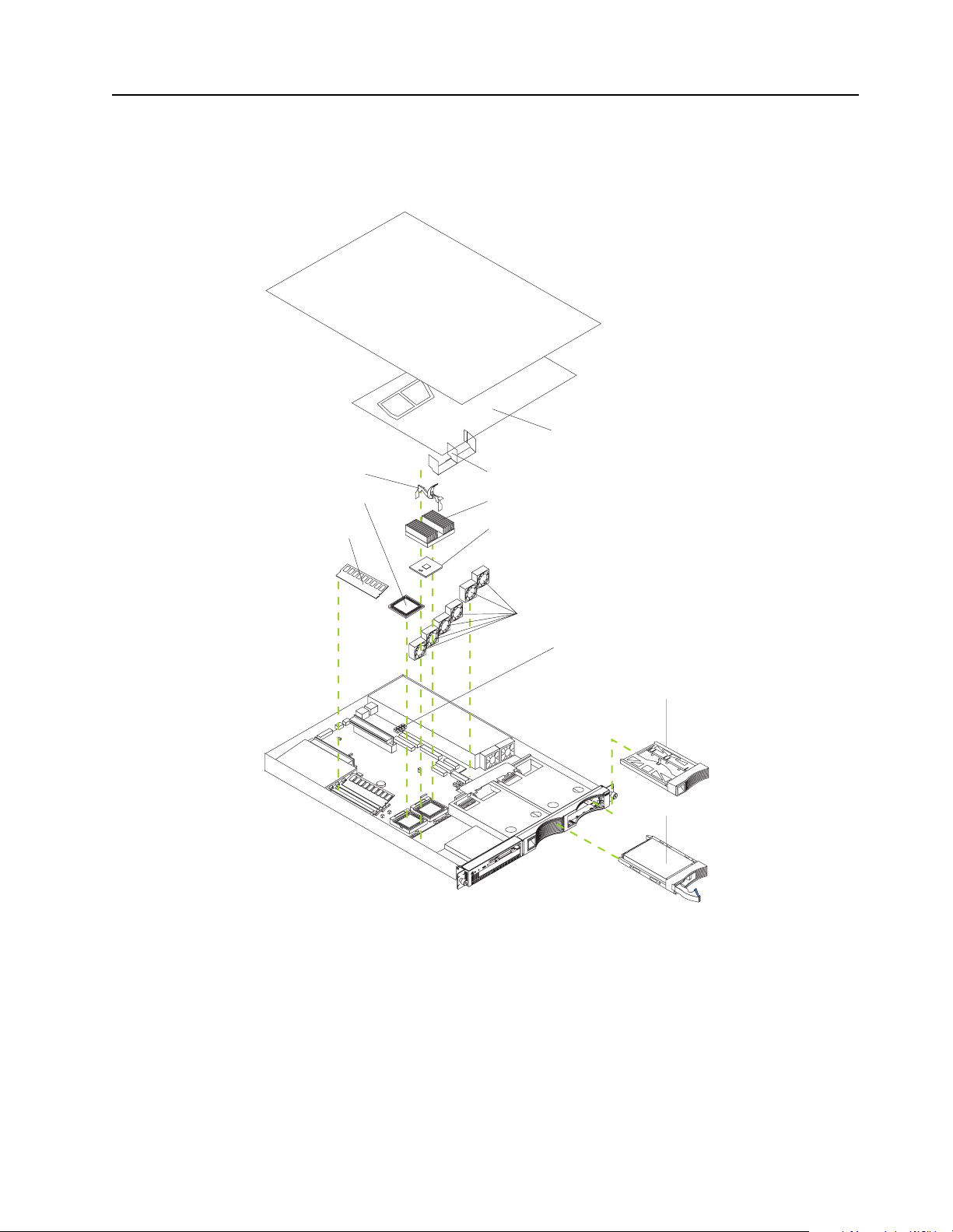
Major components of the xSeries 330 server
The following illustration shows the locations of major com p onents in your server.
Note: The illustrations in this document might differ slightly from your hardware.
Clear shield
Clip
Terminator card
Memory module
Air baffle
Heatsink
Microprocessor
Fans
Light Path
Diagnostics
Hard disk drive
filler panel
Hard disk drive
Chapter 1. Introduction 5
Page 18

6 IBM® xSeries 330: Installation Guide
Page 19
Chapter 2. Installing Options
This chapter provides basic information that is needed to install hardware options in
your server . For more detailed installation information, ref er to the User’s R efer ence on
the IBM xSeries Documentation CD.
Working with adapters
Y our server comes with two peripheral component inter connect (PCI) adapter slots on
the system board with riser cards installed in them.
Attention: Your server comes with an integrated video controller on the system
board. When you install a video adapter in a PCI slot, the server BIOS automatically
disables the integrated video controller. This allows the video adapter in the PCI slot
to control the video functions for your monitor.
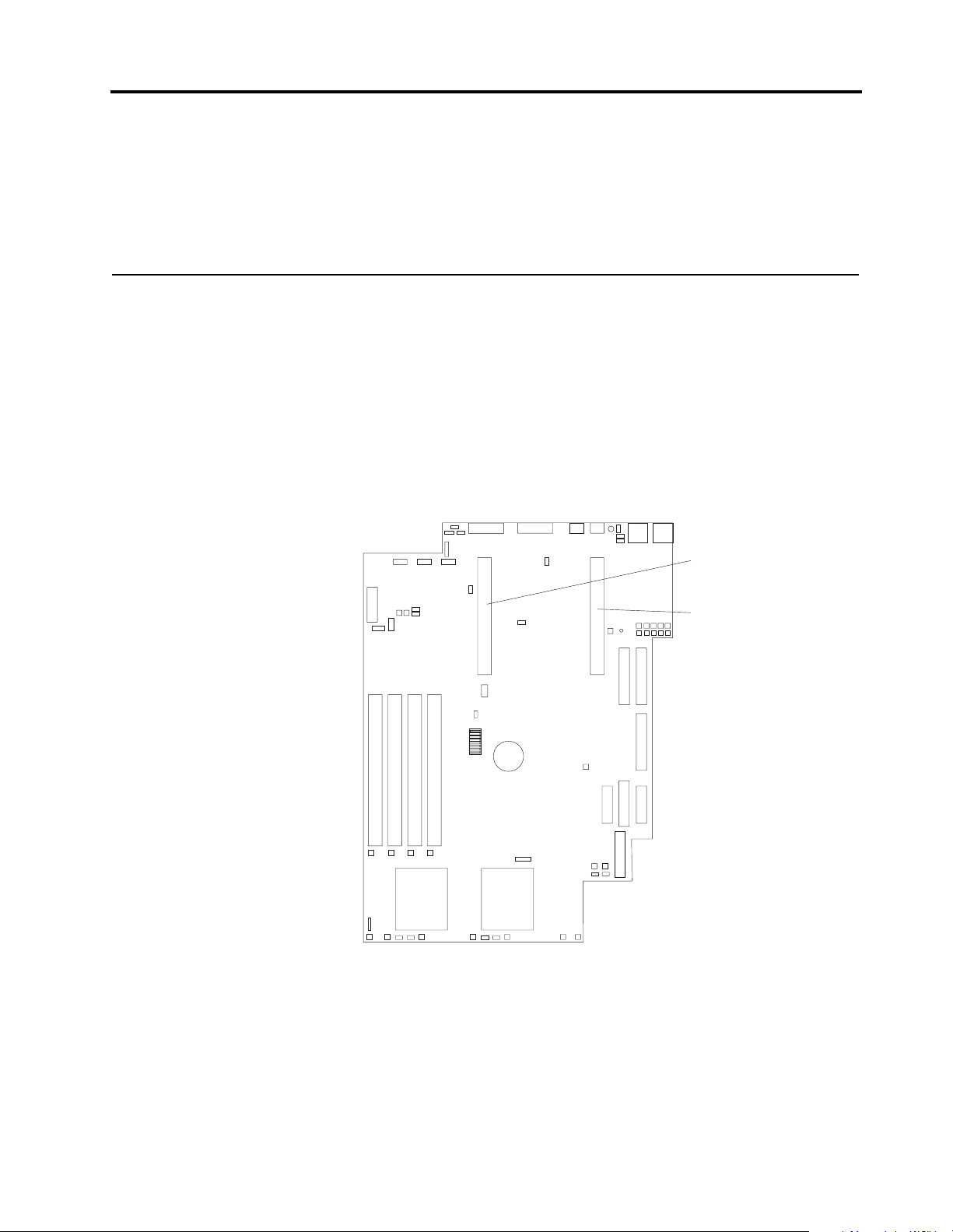
The following illustration shows the location of the 33 MHz PCI expan sion slots on
the system board.
Note: The illustrations in this document might differ slightly from your hardware.
PCI slot 2
64 bit
33 MHz (J23)
PCI slot 1
64 bit
33 MHz (J10)
© Copyright IBM Corp. 2000 7
Page 20

Adapter considerations
Before you install adapters, review the following:
• Locate the documentation that comes with the adapter and follow those
instructions in addition to the instructions in this chapter. If you need to change
the switch settings or jumper settings on your ada pter, follow the instructions
that come with the adapter.
• You can install 32-bit or 64-bit full-length or half-length adapters in the
expansion slots. Full-length adapters are installed in slot 1; half-length adapters
are installed in either slot 1 or 2.
• Your server supports 5.0V and universal PCI adapters; it does not support 3.3V
only adapters.
• Your server uses a rotational interrupt technique to configure PCI adapters.
Because of this technique, you can install PCI ad apters that currently do not
support sharing of PCI interrupts.
• PCI slots 1 and 2 and the integrated SCSI controller are on PCI bus B; the system
board and all other integrated devices are on PCI bus A.
Note: PCI bus A = bus 0; PCI bus B = bus 1.
• The system scans PCI slots 1 and 2 to assign system resources. By default, the
system starts (boots) devices in the following order: System SCSI devices, then
PCI devices.
Note: To change the boot precedence, start the Configuration/Setup Utility,
select Start Options from the main menu. Then, select the PCI SCSI
adapter boot option.
Installing an adapter
Complete the following steps to install an adapter:
Attention: When you handle electrostatic discharge (ESD) sensitive devices, take
precautions to avoid damage from static electricity. For details on handling these
devices, refer to “Handling static sensitive devices” on page 4.
1. Review the safety precautions beginning on page v.
2. Turn off the server and peripheral devices.
3. Remove all external cables from the server; then, remove the server fr om the rack
and remove the cover as shown. For more information on removing the cover,
refer to the User’s Reference on the IBM xSeries Documentation CD.
Cover release
lever
Screws
4. Remove the expansion slot clip that holds the expansion slot cover in place by
sliding it upward and off the frame of the server.
8 IBM® xSeries 330: Installation Guide
Page 21
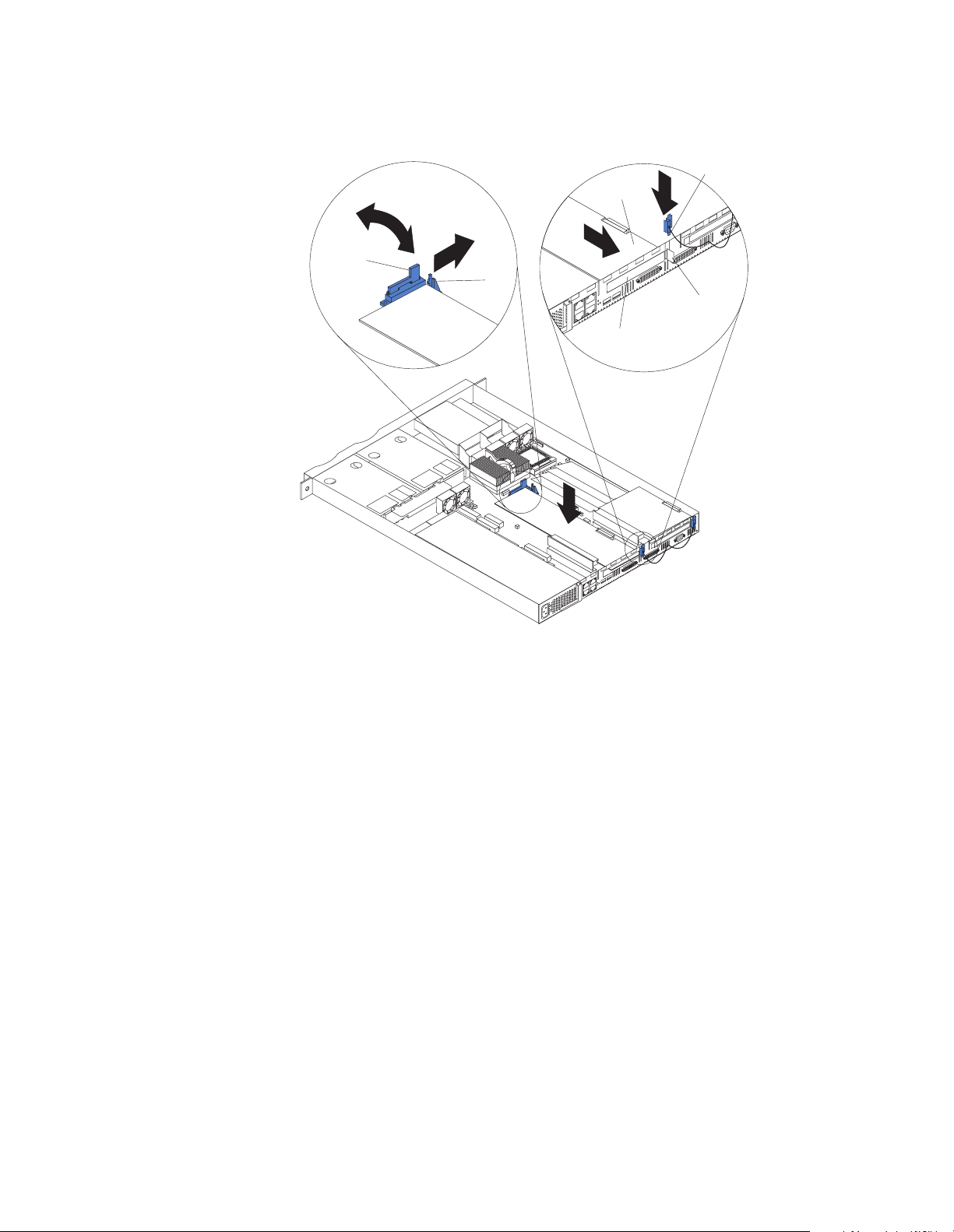
Note: The illustrations in this document might differ slightly from your
hardware.
Expansion
Adapter
card
Retention
latch
Tab
Expansion
slot
slot clip
Expansion
slot cover
5. Remove the expansion-slot cover.
6. Refer to the documentation that comes with your adapter for any cabling
instructions.
Attention: You should route adapter cables before you install the adapter.
Note: When installing a ServeRAID adapter, remove the cable from the SCSI
connector (J4) on the system board and attach it to the ServeRAID
adapter.
7. Set any jumpers or switches as described by the adapter manufacturer.
8. Install the adapter:
Note: When installing an adapter into slot 2, skip steps a and d.
a. Open the adapter retention latch by pushing the blue tab to release it. Then,
push the latch up to the full open position.
b. Carefully grasp the adapter by its top edge or upper corners, and align it with
the connector on the PCI riser card.
c. Press t he adapter firmly into the riser-card connector.
Attention: When you install an adapter, be sure the adapter is correctly
seated in the riser-card connector before you turn on the server. Improperly
seated adapters might cause damage to the system board, the riser card, or
the adapter.
Chapter 2. Installing Options 9
Page 22
d. Push down on the blue adapter retention latch until it clicks into place,
securing the adapter.
e. Replace the expansion slot clip by slidin g it down until it latches into place
and holds the adapter securely.
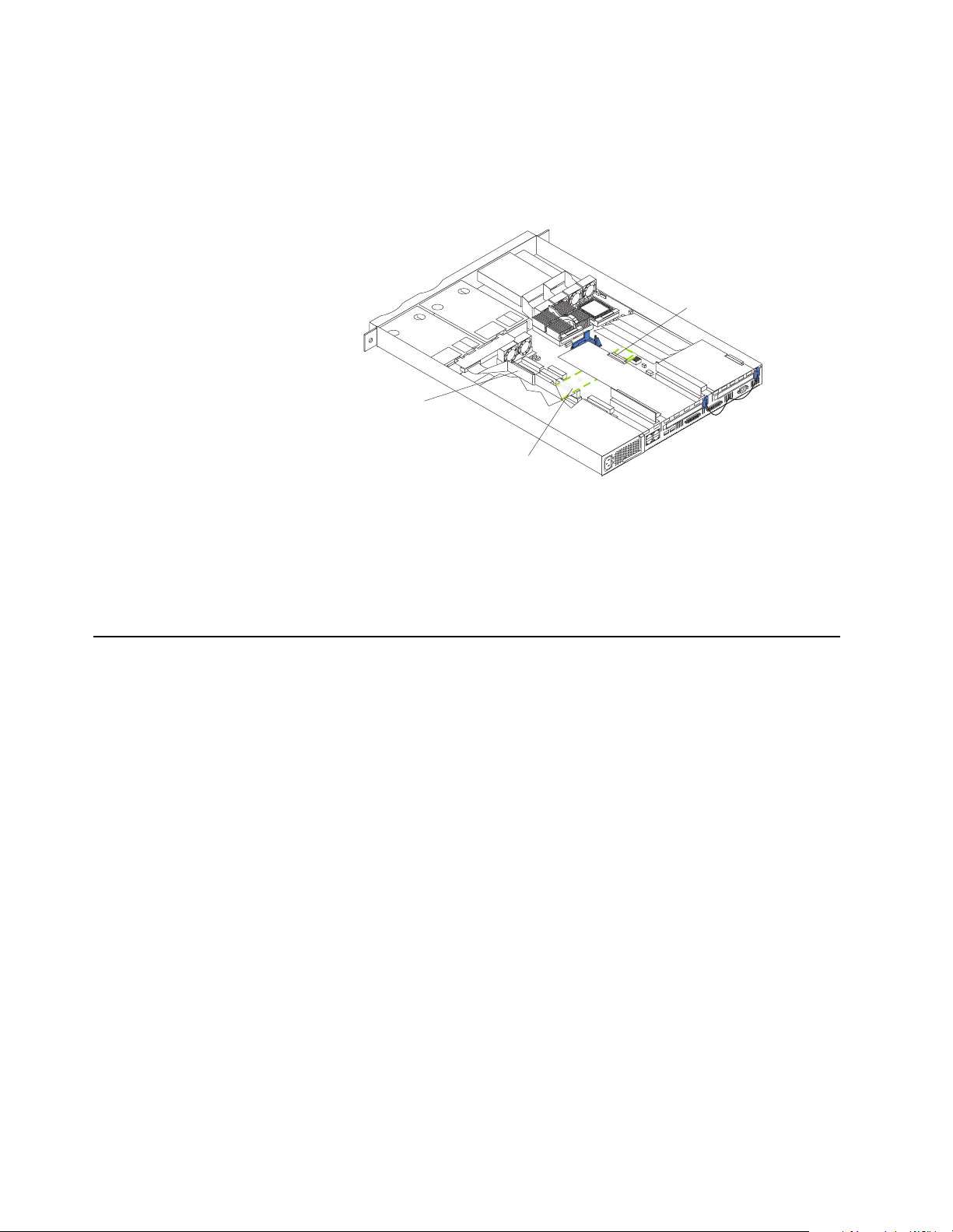
9. Connect the internal cables to the adapter.
Attention: Route cables so that they do not block the flow of air from the fans.
ServeRAID
adapter card
Extra cable
length
SCSI connector
(J4)
10. If you have other options to install, install them now.
11. Replace the cover on the server; then, reinstall the server in the rack and connect
all external cables. For more information on re placing the cover, r efer to the User’ s
Reference on the IBM xSeries Documentation CD.
12. Turn on the server.
Working with memory
Your xSeries 330 server supports 128 MB, 256 MB, 512 MB , and 1 GB DIMMs. See the
ServerProven list at http://www.ibm.com/pc/compat for a list of memory modules
for use with your server.
Memory considerations
Before you install memory, review the following:
Install additional DIMMs in the following order: DIMM connector 2, then 3, then 4.
(See the following illustration for memory connector locations.)
Note: The illustrations in this document might differ slightly from your hardware.
10 IBM® xSeries 330: Installation Guide
Page 23

Connector 4
Installing memory modules
Complete the following steps to install a DIMM:
1. Review the safety precautions beginning on page v.
2. Turn off the server and peripheral devices.
3. Remove all external cables from the server; then, remove the server fr om the rack
and remove the cover. For more information on removing the cover, refer to the
User’s Reference on the IBM xSeries Documentati on CD.
Attention: When you handle electrostatic discharge (ESD ) sensitive devices, take
precautions to avoid damage from static electricity. For details on handling these
devices, refer to “Handling static sensitive devices” on page 4.
4. If necessary, remove the PCI adapter in slot 2 for easier access to the DIMM
connectors.
5. T ouch the static-protective package containing the DIMM to any unpainted metal
surface on the server. Then, remove the DIMM from the package.
Attention: To avoid breaking the retaining clips or damaging the DIMM
connectors, handle the clips gently.
6. Install the DIMM in the connector.
Attention: To prevent damage to the DIMM connectors, do not for ce the memory
module into the connector.
a. Turn the DIMM so that the index slots align correctly with th e connector.
Note: The DIMM has two index slots, one in the center an d the other on the
left half of the DIMM connector edge.
b. Insert the DIMM into the connector by pressing on both corners of the DIMM
at the same time. Be sure to press it straight into the connector.
c. When installing a memory module, be sure that no gap exists between the
DIMM and the retaining clips. If a gap does exist between the memory
module and the retaining clips, remove the DIMM; then, reinsert the DIMM
properly.
Connector 1
Connector 2
Connector 3
Chapter 2. Installing Option s 11
Page 24

Connector 1
Connector 2
Connector 3
Connector 4
Note: If you have other options to install, install them now.
7. Replace the cover on the server; then, reinstall the server in the rack and connect
all external cables. For more information on re placing the cover, r efer to the User’ s
Reference on the IBM xSeries Documentation CD.
8. Turn on the server.
12 IBM® xSeries 330: Installation Guide
Page 25

Working with hard disk drives
Your server supports two, 1-inch (26 mm) slim 3.5-inch low voltage differential (LVD)
hard disk drives. If a ServeRAID adapter configured in a RAID 1 configuration is
installed in your system, you can hot swap h ard disk drives.
Note: Refer to the User’s Reference on the IBM xSeries Documentation CD for
information on ServeRAID adapters and hot swapping hard disk drives.
Hard disk drive considerations
Before you install a hard disk drive, review the following:
• Inspect the drive tray for any signs of damage.
• Ensure that the drive is installed properly in the tray.
• To maintain proper system cooling, do not operate the server for more than two
minutes without either a drive or a filler panel installed in each bay.
• If your server has a ServeRAID adapter installed, refer to the documentation
provided with the ServeRAID adapter for information about adding a drive.
• You can hot swap a hard disk drive only if a ServeRAID adapter configured as
RAID 1 is installed in your system. If you use any other ServeRAID or SCSI
configuration, you can not hot swap the hard disk drive.
Note: For instructions on how to install and replace a hot-swap drive, refer to
the documentation provided with the ServeRAID adapter and to the
User’s Reference on the IBM xSeries Documentation CD.
Installing a hard disk drive
Refer to the following illustration to install a hard disk drive.
Note: The illustrations in this document might differ slightly from your hardware.
Attention: When you handle electrostatic discharge (ESD) sensitive devices, take
precautions to avoid damage from static electricity. For details on handling these
devices, refer to “Handling static sensitive devices” on page 4.
Complete the following steps to install or replace a hard disk drive:
1. Review the safety precautions beginning on page v.
2. Turn off the server and peripheral devices and disconnect all external cables and
power cords.
Slim filler
Filler panel
Hard disk drive
Drive tray
Drive tray handle
(in open position)
Chapter 2. Installing Option s 13
Page 26

3. Remove the filler panel or defective hard drive from one of the hard disk drive
bays.
4. Install the new hard disk drive in the drive bay:
a. Ensure the tray handle is open (that is, perpendicular to the drive).
b. Align the rails on the drive assembly with the guide rails in the drive bay.
c. Gently push the drive assembly into the ba y until the drive connects to the
backplane.
d. Push the tray handle toward the closed position until it locks the drive in
place.
5. Reconnect the external cables and power cords; then, turn on the server.
6. Check the hard disk drive status indicators to verify that the hard disk drives are
operating properly. (See “Server controls and indicators” on page 25 for the
location of the status indicators.)
Notes:
a. The green light flashes rapidly (three flashes per second) when the controller
is identifying the drive.
b. Replacing a hard disk drive is done in the same manner as insta lling a new
hard disk drive, but you must remove the old hard disk drive first.
c. If your server has a ServeRAID adapter installed, you can hot swap drives.
For more information about hot swapping drives, refer to the documentation
provided with the ServeRAID adapter and to the User’s Reference on the IBM
Documentation CD.
Working with microprocessors
Microprocessors are sensitive to electrostatic discharge (ESD) and should be handled
with care.
Attention: When you handle electrostatic discharge sensitive devices, take
precautions to avoid damage from static electricity. For details on handling these
devices, refer to “Handling static sensitive devices” on page 4.
Your server comes with one or two microprocessors installed.
Servers with 1 microprocessor installed:
• Microprocessor is installed in microprocessor socket 1 (U47).
• Microprocessor supports both the startup and application processes.
• A terminator card is installed in microprocessor socket 2 (U79).
Servers with 2 microprocessors installed:
• One microprocessor is installed in microprocessor socket 1 (U47 ) and the second
microprocessor is installed in socket 2 (U79).
• Both microprocessors share the system load.
14 IBM® xSeries 330: Installation Guide
Page 27

Microprocessor considerations
Before you install a microprocessor, review the following:
• Ensure that the microprocessors are the same type, and have the same cache
size, and have the same clock speed.
• Ensure that the microprocessor internal and external clock frequencies are
identical.
• See the ServerProven list at http://www.ibm.com/pc/compat for a list of
microprocessors for use with your server.
Installing a microprocessor
Complete the following steps to install a microprocessor:
Note: The illustrations in this document might differ slightly from your hardware.
Microprocessor 2
(U79)
Microprocessor 1
(U47)
Attention: To avoid damage and ensure proper server operation, install
microprocessors that are the same type, and have the same cache size, and have the
same clock speed. Microprocessor internal clock frequencies and external clock
frequencies must be identical. See the ServerProven list at
http://www.ibm.com/pc/compat for a list of microprocessors for use with your
server.
Note: The illustrations in this document might differ slightly from your hardware.
Chapter 2. Installing Option s 15
Page 28

Slot
Top view of
heatsink
Terminator card
Heatsink release
lever
Clip
Heatsink
Microprocessor
Attention: When you handle electrostatic discharge (ESD) sensitive devices, take
precautions to avoid damage from static electricity. For details on handling these
devices, refer to “Handling static sensitive devices” on page 4.
1. Review the safety precautions beginning on page v.
2. Turn off the server and peripheral devices.
3. Remove all external cables from the server; then, remove the server fr om the rack
and remove the cover. For more information on removing the cover, refer to the
User’s Reference on the IBM xSeries Documentati on CD.
4. Remove the plastic shield from the server.
5. Lift up the microprocessor release lever and remove the terminator card from the
microprocessor connector.
6. Install the microprocessor in the microprocessor connector.
Attention: To avoid bending the pins, do not use excessive force.
7. Push the release lever down to lock the microprocessor into place.
8. Install the heat sink onto the microprocessor.
9. Replace the clear shield.
Notes:
a. The clear shield must be installed to maintain proper air flow and cooling
inside the server.
b. If you have other options to install, install them now.
10. Replace the cover on the server; then, reinstall the server in the rack and connect
all external cables. For more information on re placing the cover, r efer to the User’ s
Reference on the IBM xSeries Documentation CD.
11. Turn on the server and run the Configuration/Setup Utility program.
16 IBM® xSeries 330: Installation Guide
Page 29

Working with cables
Y our server has two different cabling options, the Advanced System Manageme nt bus
(ASM) and the cable chain technology (C2T). The following sections discuss each of
these options. While reading about these options, keep in mind that they are
independent of each other.
Note: Refer to the following illustration to locate the connectors on the back of your
The ASM ports on the back of the server will be referred to in this book as
RS-485 (A) and RS-485 (B).
Note: The illustrations in this document might differ slightly from your hardware.
Ethernet 1
server .
RS-485 (Advanced
System Management
Interconnect) A
PCI slot 1
PCI slot 2
Ethernet 2
USB 1
RS-485 (Advanced
System Management
Interconnect) B
Cabling the RS-485 ports
You can use the RS-485 connectors to create an Advanced System Management bus
between several xSeries 330 servers.
Before you begin, review the following:
Important: The Advanced System Management bus is designed to support up to 12
units or servers. However, when using the Advanced System Management PCI
adapter, the bus uses the PCI adapter as another unit. In this case, you can connect a
maximum of 11 units or servers together.
• You can hot swap the cables in the Advanced System Management bus.
• You can connect up to 12 units together, if you are using serial (management)
port A as your Advanced System Management port.
• When connecting an xSeries 330 server to another server type, you must install
an Advanced System Management adapter in PCI slot 1 or use the serial port as
your Advanced System Management port.
• Use standard cables with RJ-14 connectors.
USB 2
Console out
Console in
Serial port
Note: For more information about the Advanced System Management PCI adapter,
refer to the documentation that came with the adapter.
Chapter 2. Installing Option s 17
Page 30

Connecting the ASM bus
The servers in the Advanced System Management (ASM) bus are referenced by their
assigned addresses and not their position in the rack.
Complete the following steps to connect the ASM bus:
1. Turn off the servers.
2. Locate the RS-485 ports on the rear of the servers and several cables with RJ-14
connectors on both ends.
3. Starting at the top most server to be included in the ASM bus connect one end of
the cable into the RS-485 (B) port and the other end o f the cable into the RS-48 5 (A)
port of the next server.
4. Continue connecting the servers together in this manner until you reach the
second to last server in the ASM bus.
5. Connect a cable from the RS-485 (B) port of the secon d to last serve r to the RS-48 5
(B) port of the last server . Refer to the following illustration to see how to connect
the ASM bus.
Note: The illustrations in this document might differ slightly from your
hardware.
Ethernet cable
with RJ-14 connectors
RS-485(A)
RS-485(B)
RS-485(B)
RS-485(B)
6. Turn on the servers.
RS-485(A)
RS-485(A)
18 IBM® xSeries 330: Installation Guide
Page 31

Connecting the servers with a C2T chain
To share the same monitor, keyboard, and pointing device with several servers, you
must connect the servers together with Cable Chain Technology (C2T) chaining cables
through the Console (In) and Console (Out) ports.
Before you begin, review the following:
• You can connect a maximum of 40 servers with the C2T chaining cables.
• When connecting servers on two separate racks, you must use a C2T chaining
cable that is 2-m (6.5 ft.) long, which is available in the C2T option cable kit.
Note: Only one 2-m (6.5 ft.) cable can be used in the C2T chain.
• The C2T chaining cables can not be hot swapped.
Attention: For best results, shut down the servers above and below the server
being removed from or added to the chain.
• Servers are numbered by their position in the chain (1 thr ough nn). If one server
is removed from the chain, all successive servers are renumbered. For example,
if the twelfth server is removed from a chain of 15 servers, then servers 13
through 15 will be renumbered to 12 through 14.
• The C2T numbering is independent of any other server reference. Changing the
server position in the C2T chain will not effect its IP address.
Operational notes:
1. Server 1 (usually the server at the bottom of the rack) is the server to which you
connect the C2T device break out cable.
2. Server 1 must not be turned off (powered down), for the chain to work properly.
3. If server 1 is turned off (powered down), it must be removed from the chain and
replaced by the next server in the chain.
4. For the chain to operate properly, no more than two adjacent servers can be
unplugged from the wall outlet at the same time.
5. If you are using a flat-panel monitor, you might need to adjust the image lock on
your monitor when multiple servers are connected using C2T chaining cables. To
adjust this image, select one of the middle servers in the chain by pressing the
select button on the front of the server; then, adjust the image lock accordingly.
For more information on how to adjust the image lock, r efer to the documentation
that came with your flat-panel mo nitor.
6. When removing or replacing servers, or changing cables in the chain, it is possible
for more than one select LED to be illuminated on the servers in the chain. To
clear all but the selected server LED, press the select button on any one of the
servers in the chain.
7. If you turn off a selected server, you must select another server that is powered
up. For the location of the select button, see page “Front view” on pag e 25.
Chapter 2. Installing Option s 19
Page 32

Complete the following steps to connect the servers:
1. Gather several of the C2T chaining cables.
Note: Your server comes with a short C2T chaining cable that can span
approximately 3 U’s, if needed. A longer C2T cable is available in the
C2T cable kit.
2. Connect the servers together:
a. Connect one end of the C2T chaining cable to the Console (Out) port of the
top server.
b. Connect the opposite end of the C2T chaining cable to the Console (In) port of
the server below it. Refer to the following illustration for additional
information.
c. Repeat these steps until all of the servers are connected together.
d. Connect the C2T device break out cable to the server 1 Console (Out) port.
Note: Server 1 (usually the server at the bottom of the rack) is the server to
which you connect the device break out cable.
3. Turn the servers on and check the operation of the monitor, pointing device, and
keyboard with each server. (See “Testing the C2T chain” on page 21 for testing
instructions.)
4
In
In Out
In
In
Video
Out
3
2
Out
1
Out
Mouse
Keyboard
Note: Write-on adhesive labels have been provided so that you can label the server
position in the rack.
20 IBM® xSeries 330: Installation Guide
Page 33

Testing the C2T chain
After connecting the C2T chain, you will need to test the monitor, keyboard, and
pointing device to be sure that they work with each of the servers.
Follow these steps to test the C2T cabling:
1. With the servers powered up and the monitor on, press the select button on server
1 in the C2T chain.
2. Check the monitor to see if it is working.
3. Use the mouse or pointing device to open an application.
4. Test your keyboard by typing a few words within an application.
5. Repeat steps 1 through 4 for each of the servers in the chain.
Note: If you cannot use the devices, check your cable connections and retry the test.
If the problem persists, turn off the servers and connect the C2T device break
out cable directly to the Console (Out) port of the server. Power up the server
and retry the devices. If the devices work, then you probably have a bad C2T
chaining cable. Replace the cable and retry the devices in the C2T chain
configuration.
Cable management
Use the cable ties and hook-and-loop straps that are supplied with your server to
secure the cables.
Note: Do not secure cables too tightly. Over tightening can cause internal damage
to cables.
Chapter 2. Installing Option s 21
Page 34

22 IBM® xSeries 330: Installation Guide
Page 35

Chapter 3. Server power, controls and indicators
1
2
This chapter describes how to turn on and turn off the server, and what the controls
and indicators mean.
Turning on the server
Turning on the server refers to the act of plugging the power cord of your server into
the power source and starting the operating system.
Complete the following steps to turn the server on:
1. Plug the power cord of your server into the power source.
Note: Plugging the power cord into a power source may cause the server to
start automatically. This is an acceptable action.
2. Wait 30 seconds then press the power control button on the front of the server.
Statement 5
CAUTION:
The power control button on the device and the power switch on the p ower supply
do not turn off the electrical current supplied to the device. The device also might
have more than one power cord. To remove all electrical current from the device,
ensure that all power cords are disconnected from the power source.
© Copyright IBM Corp. 2000 23
Page 36

Turning off the server
Turning off the server refers to the act of disconnecting the server from the power
source.
Complete the following steps to turn off the server:
1. Refer to your operating system documentation for the proper procedure to shut
down the operating system.
Note: Each operating system is different. Some will allow an immediate shut
2. Press the power control button on the front of the server. This will put the server
in stand-by mode.
3. Disconnect the server from the power source.
Note: After you turn off the server, wait at least 5 seconds before you turn on
Stand-by mode
Stand-by puts the server in a wait state. When in a wait state, the server is not
running the operating system, and all core logic is shut down except for the service
processor.
down, while others require an orderly shut-down procedur e.
the server again.
Complete the following steps to put the server into the stand-by mode:
1. Refer to your operating system documentation for the proper procedure to shutdown the operating system.
Note: Each operating system is different. Read all the documentation about
shutting down the operating system before continuing.
2. Press the power control button on the front of the server.
24 IBM® xSeries 330: Installation Guide
Page 37

Server controls a nd indicators
This section identifies the controls and indicators on the front and the back of your
server.
Front view
Power control
button
Power-on
light (green)
Reset
button
Select
button/indicator
(green)
System error
light (amber)
Diskette drive
activity light
(green)
Diskette eject
button
Hard disk drive
status light (amber)
light (green)
CD eject buttonCD activity
Hard disk drive
activity light (green)
Power-control button: Press this button to manually turn the server on or off.
Power-on light: This green LED lights and stays on when you turn on your server
and blinks when the server is in stand-by mode.
Reset button: Press this button to reset the server and run the power-on self-test
(POST). You might need to use a pen or the end of a straightened paper clip to press
the button.
Select button/indicator: Press this button to select the server in the C2T chain. The
green LED on this button lights when the monitor, keyboard, and mouse are logically
connected to this server.
System-error light: This amber LED lights when a system error occurs. An LED on
the Light Path Diagnostic panel on the system board will also be on to further isolate
the error.
Diskette drive activity light: When this LED is on, it indicates that the diskette drive
is in use.
Diskette-eject button: Push this button to release a diskette from the drive.
Hard disk drive status light: Each of the hot-swap drives has a hard disk drive status
light. When this amber LED is on continuously, the drive has failed. This status light
is active only with a ServeRAID adapter installed in the server.
Hard disk drive activity light: Each of the hot-swap drives has a Hard Disk Activity
light. When this green LED is flashing, the controller is accessing the drive.
CD eject button: Push this button to release a CD from the drive.
CD drive activity light: When this light is on, it indicates that the CD-ROM drive is in
use.
Chapter 3. Server power, controls and indicators 25
Page 38

Rear view
Ethernet 1 speed
indicator (green)
Ethernet 1 link
indicator (green)
Advanced systems
management RS-485
Select light (green)
Console port out
Ethernet 2 speed
indicator (green)
Ethernet 2 link
indicator (green)
Power-on light
(green)
USB 2
USB 1
System error
light (amber)
Serial port
Console port in
Ethernet 1 speed indicator: This green LED lights when the speed of the Ethernet
LAN that is connected to Ethernet port 1 is 100 Mbps.
Ethernet 1 link indicator: This green LED lights when there is an active link
connection on the 10BASE-T or 100BASE-TX interface for Ethernet port 1.
Advanced system management: The RS-485 ports are used for creating a system
management bus between several servers.
Select light: This green LED lights when the monitor, keyboard, and mouse are
logically connected to this server. This light duplicates the Select button LED on the
front of the server.
Console port out: This port is used to connect the server to a keyboard, monitor, and
pointing device. It is also used to connect multiple servers together to share a single
keyboard, monitor, and pointing device.
Serial port: Signal cables for modems or other serial devices connect here to the 9-pin
serial port connector.
Console port in: This port is used to connect multiple servers together to share a
single keyboard, monitor, and pointing device.
USB 2: Universal Serial Bus 2
USB 1: Universal Serial Bus 1
System-error light: This amber LED lights when a system error occurs. An LED on
the Light Path Diagnostic panel on the system board will also be on to further isolate
the error. This light duplicates the system error light on the front of the server.
Power-on light: This green LED lights and stays on when you turn on your server
and will blink when the server is in standby mode. This light duplicates the power on
light on the front of the server.
Ethernet 2 link indicator: This green LED lights when there is an active link
connection on the 10BASE-T or 100BASE-TX interface for Ethernet port 2.
Ethernet 2 speed indicator: This green LED lights when the speed of the Ethernet
LAN connected to Ethernet port 2 is 100 Mbps.
26 IBM® xSeries 330: Installation Guide
Page 39

Chapter 4. Configuring your server
The following configuration programs are provided with your server:
• Configuration/Setup Utility
The Configuration/Setup Utility program is part of the basic input/output system
(BIOS) code that comes with your server. You can use this program to configure
serial port assignments, change interrupt request (IRQ) settings, change the
drive startup sequence, set the date and time, and set passwords.
• SCSISelect Utility
With the built-in SCSISelect Utility program, you can configure the devices that
are attached to the integrated SCSI controller. Use this program to change
default values, resolve configuration conflicts, and perform a low-level format
on a SCSI hard disk drive.
• PXE Boot Agent Utility
The Preboot eXecution Environment (PXE) Boot Agent Utility program is part of
the basic input/output system (BIOS) code that comes with your server. You can
use this program to change network boot protocols and boot order, to select OS
wake up support, and to set menu wait times.
• ServerGuide CDs
The ServerGuide CDs include software setup and installation tools specif ically
designed for IBM servers. Y ou can use these CDs during the initial installation of
your server to configure the server hardware and simplify your network
operating system installation. The ServerGuide CDs also contain a collection o f
application programs, which you can install after your server is up and running.
See “Using the ServerGuide CDs” on page 28 for more detailed information.
• ServeRAID programs
If you have a ServeRAID adapter installed in your server, you must use the
ServeRAID configuration program to define and configure your disk-array
subsystem before you install your operating system.
Note: Refer to the User’s Reference on the IBM xSeries Documentation CD for
detailed instructions for using the configuration programs.
© Copyright IBM Corp. 2000 27
Page 40

Using the ServerGuide CDs
The ServerGuide CDs provide state-of-the-art programs to detect the server model
and hardware options that are installed, configure server hardware, provide device
drivers, and install your network operating system (NOS).
Note: If the ServerGuide CD does not start, see “ServerGuide startup problems” on
page 32.
1. Insert the Setup and Installation CD, and restart the server.
2. Follow the on-screen instructions to:
a. Select your language.
b. Select your keyboard layout and country.
c. View the overview to learn about ServerGuide features.
d. View the README file to review installation tips about your NOS and
adapter.
e. Start the setup and hardware configuration programs.
f. Start the NOS installation. You will need your copy of the NOS CD.
Note: For information on the supported NOS versions, refer to the Setup and
Installation CD label.
System management solutions
Your server includes IBM system management software. This system management
software is a comprehensive set of hardware management utilities. These utilities
enable you to manage industry-standard, Intel-processor-based, server, desktop,
workstation, and notebook systems over network operating systems from Microsoft,
SCO, Novell, and IBM. These utilities support multiple protocols, including TCP/IP,
IPX, NetBIOS, SNA, SLIP, and HTTP. This robust set of systems management
software tools delivers comprehensive local and remote system control over the entire
life cycle of the system.
28 IBM® xSeries 330: Installation Guide
Page 41

Chapter 5. Solving problems
Solving problems
This section provides basic troubleshooting informa tion to help you resolve some
common problems that might occur while setting up yo ur server.
If you cannot locate and correct the problem using the information in this section ,
refer to the " Solving problems" section in the User’s Reference on the IBM xSeries
Documentation CD and the "Server Support" flowchart in the front of this booklet for
additional information.
Diagnostic tools overview
The following tools are available to help you identify and resolve hardware-related
problems:
• Beep codes and error messages
The power-on self-test (POST) generates beep codes to indicate successful test
completion or the detection of a problem.
— One beep indicates successful completion of POST.
— More than one beep indicates that POST detected a problem. Error
messages also appear during startup if POST detects a hardwareconfiguration problem.
See “POST beep code descriptions” on page 30 and “POST error messages” on
page 30 for more information.
• Troubleshooting chart
This chart lists problem symptoms and suggested steps to correct the problems.
See the “Troubleshooting charts” on page 33 for more information.
• Event or error logs
The system event or error log contains all error messages that are issued during
POST and all system status messages from the Advanced System Management
Processor.
To view the contents of the error logs, start the Configuration/Setup Utility
program; then, select Event/Error Logs from the main menu.
• Diagnostic programs and error messages
The server diagnostic programs are stored in the read-only memory (ROM) on
the system board. These programs are the primary method of testing the major
components of your server.
Note: Re fer to the "Solv ing Pr oblem s" se ctio n in t he Us er’s Refe renc e on th e IBM
xSeries Documentation CD for more detailed information about the
diagnostic programs.
• Light Path Diagnostics
The Light Path Diagnostics is used to quickly identify system errors. For more
information about the Light Path Diagnostic refer to the "Solving Problems"
section in the User’s Reference on the IBM xSeries Docume ntation CD.
© Copyright IBM Corp. 2000 29
Page 42

POST beep code descriptions
POST emits one beep to signal successful completion. If POST detects a problem
during startup, other beep codes might occur. You can use the following beep code
descriptions to help identify and resolve problems that are detected during startup.
Note: Refer to the "Solving Problems" section in the User’s Reference on the IBM
Documentation CD for more detailed information about the POST beep codes.
Beep code Descriptions of the POST beep codes
No beep Call for service.
Continuous If no video appears, the startup microprocessor failed. Verify that the startup microprocessor is
installed correctl y. If it is, replace the star tup mic roprocessor. If th e problem persists, call for serv ic e.
One short POST completed successfully. One beep also occurs after POST if you enter an incorrect password.
Two short Follow the instructions that appear on the screen.
Three short POST detected a system memory error. Verify that the memory is installed correctly. If it is, replace
the failing memory module.
Repeating short The system board might contain a failing component.
1. Verify that the keyboard and pointing devices are connected properly.
2. Ensure that nothing is resting on the keyboard.
3. Disconnect the pointing device; then, restart the server. If the problem goes away, replace the
pointing device. If the problem remains, call for service.
One long and
one short
One long and
two short
One long and
three short
Two long and
two short
All other beep
codes
If the video controller on the system board is being used, call for service. If you installed an optional
video adapter, replace the failing adapter.
A video I/O adapter ROM is not readable, or the video subsystem is defective. If you installed an
optional video adapter, replace the failing adapter. If the problem remains, call for service.
The system-board video subsystem has not detected a monitor connection to the server. Ensure that
the monitor is connected to the server. If the problem persists, replace the monitor.
POST does not support the optional vi deo ada pte r. Re place t he optiona l v id eo adapt er wi th one t hat
is supported by the server or use the integrated video controller.
1. Verify that the system memory modules are installed correctly.
2. Turn off the server; then, restart the server. If the problem remains, call for service.
Table 2. Post beep code descriptions
POST error messages
The following table provides an abbreviated list of the error messages that might
appear during POST.
Note: Refer to the "Solving Problems" section in the User’s Reference on the IBM
xSeries Documentation CD for more detailed information about POST error
messages.
30 IBM® xSeries 330: Installation Guide
Page 43

POST message Failing device or problem found Suggested action
129 L1 cache of a microprocessor Check the installation of your microprocessors.
162 Change in device configuration Verify that your optional devices are turned on and
installed correctly.
163 Time of day has not been set Set the correct date and time.
164 Change in memory configuration Verify that your memory is installed properly; then, restart
the server and run the Configuration/Setup Utility
program.
201 Change in memory configuration Verify that your memory is fully seated and installed
properly.
229 L2 cache of a microprocessor Check the installation of your microprocessors.
289 Failing DIMM was disabled Verify that your memory is correct for your server and that
it is installed properly.
301
303
962 Parallel port configuration error Start the Configuration/Setup program and verify that the
11xx Serial port error Verify that the serial cable is connected correctly.
1162 Serial port configuration conflict Start the Configuration/Set up program and ensur e t ha t the
1601 Service Processor update needed Download and install the latest system Service Processor
1800 PCI adapter hardware interrupt Start the Configuration/Setup program and verify that the
1801 PCI adapter out of ROM space error Remove a PCI adapter or disable a PCI device in the
2400
2462
00019xxx Microprocessor x is no t functio ning or
00180xxx A PCI adapter requested a resource
Keyboard and keyboard controller Ensure that the keyboard cable is connected and nothing is
resting on the keyboard keys.
parallel-port setting is correct.
IRQ and I/O port assignments needed by the seria l port ar e
available.
level.
interrupt resource settings are correct.
Configuration/Setup program.
Video controller and memory Verify that the monitor is connected correctly.
Verify that microprocessor x is installed correctly. If the
failed the built-in test
that is not available
problem remains, replace microprocessor x.
Start the Configuration/Setup program and ensure that the
resources needed by the PCI adapter are available.
012980xx
012981xx
01298200 Microprocessor speed mismatch Install microprocessors with identical speeds.
I9990305 POST could not find an operating
Data for microprocessor x Download and install the latest version of the system BIOS.
Install your operating system.
system.
Table 3. Post error messages
Chapter 5. Solving problems 31
Page 44

ServerGuide startup problems
Look for the symptom in the left column of the chart. Probable solutions to the
problem are in the right column.
Setup Suggested action
Setup and Installation CD
will not start.
ServeRAID program
cannot view all installed
drives - or - cannot
install NOS.
The Operating System
Installation program
continuously loops.
ServerGuide will not
start your NOS CD.
Cannot install NOS option is grayed out.
• Ensure that the system is a supported server with a startable (bootable) CD-ROM
drive.
• If the startup (boot) sequence settings have been altered, be sure the CD-ROM is first
in the boot sequence.
• Ensure that there are no duplicate SCSI IDs or IRQ assignments.
• Ensure that the hard disk drive is connected properly.
Free up more space on the hard disk drive.
Ensure that the NOS CD you have is supported by ServerGuide. See the Setup and
Installation CD label for a list of NOS versions supported.
Either there is no logical drive defined (ServeRAID systems) or the ServerGuide system
partition is not present. Run the server guide setup and configuration program and ensure
that setup is complete
Table 4. ServerGuide startup problems
System updates and
applications CD
Get "time out" or
"Unknown host" errors
Ensure that yo u ha ve ac c ess to th e Int ernet throug h FTP d irectly.
Suggested action
Table 5. System updates and applications CD
32 IBM® xSeries 330: Installation Guide
Page 45

Troubleshooting charts
You can use the troubleshooting charts in this section to find solutions to problems
that have definite symptoms.
Attention: If diagnostic error messages appear that are not listed in the following
tables, make sure that your server has the latest levels of BIOS, ServeRAID, and
diagnostics microcode installed.
Look for the symptom in the left column of the chart. Instructions and probable
solutions to the problem are in the right column. If you ha ve just adde d new sof tware
or a new option and your server is not working, do the following before using the
troubleshooting charts:
• Remove the software or device that you just added.
• Run the diagnostic tests to determine if your server is running correctly.
• Reinstall the new software or new device.
Chapter 5. Solving problems 33
Page 46

CD-ROM drive Suggested action
CD-ROM drive is not
recognized.
Diskette drive Suggested action
Diskette drive in-use light stays
on, or the system bypasses the
diskette drive.
Expansion enclosure
problems
The SCSI expansion enclosure
used to work, but does not
work now.
Verify th at :
1. The primary IDE channel is enabled in the Configuration/Setup Utility
program.
2. All cables and jumpers are installed correctly.
3. The correct device driver is installed for the CD-ROM drive.
If there is a diskette in the drive, verify that:
1. The diskette drive is enabled in the Configuration/Setup Utility program.
2. The diskette is good and not damaged. (Try another diskette if you have one.)
3. The diskette contains the necessary files to start the server.
4. Your software program is OK.
If the diskette drive in-use light stays on, or the system continues to bypass the
diskette drive, call for service.
Suggested action
Verify th at:
1. The cables for all external SCSI options are connected correctly.
2. The last option in each SCSI chain, or the end of the SCSI cable, is terminated
correctly.
3. Any external SCSI option is turned on. You must turn on an extern al SCSI option
before turning on the server.
For more information, see your SCSI and expansion enclosure documentation.
General problems Suggested action
Problems such as broken cover
locks or indicator lights not
working.
Intermittent problems Suggested action
A problem occurs only
occasionally and is difficult to
detect.
Call for service.
Verify th at:
1. All cables and cords are conn ected securel y to the r ea r of the ser ver and at tached
options.
2. When the server is turned on, air is flowin g from the rear of the server at the fan
grill. If there is no air flow, the fan is not working. This causes the server to
overheat and shut down.
3. Ensure that the SCSI bus and devices are configured correctly and that the last
external device in each SCSI chain is terminated correctly.
If the items above are correct, call for service.
Table 6. Troubleshooting charts
34 IBM® xSeries 330: Installation Guide
Page 47

Keyboard, mouse, or
pointing-device problems.
All or some keys on the
keyboard do not work.
Suggested action
1. Make sure that the keyboard cable is prope rly connected t o the C2T device br eakout
cable.
2. Make sure that the C2T device breakout cable is properly connected to the server.
3. Make sure that the server and the monitor are turned on.
4. Try using another keyboard.
Note: If you are using the C2T chain, refer to .
If the items above are correct, call for service.
The mouse or pointing
device does not work.
1. Verify that th e mouse or poin tin g-de vice c a ble is sec urely connected and the dev ice
drivers are installed correctly.
2. Try using another mouse or pointing device.
Note: If you are using the C2T chain, refer to “Testing th e C2 T chain” on pa ge 2 1.
If the problem remains, call for service.
Memory problems Suggested actions
The amount of memory
displayed is less than the
amount of memory
installed.
Verify that:
1. The memory modules are seated properly.
2. You have installed the correct type of memory.
3. If you changed the memory, you updated the memory configuration with the
Configuration/Setup Utility program.
4. All banks of memory on the DIMMs are enabled. The server might have
automatically disabled a DIMM bank when it detected a problem or a DIMM bank
could have been manually disabled.
Look in the POST error log for error message 289:
• If the DIMM was disabled by a system-management interrupt (SMI), replace the
DIMM.
• If the DIMM was disabled by the user or by POST:
1. Start the Configuration/Setup Utility program.
2. Enable the DIMM.
3. Save the configuration and restart the server.
• If you continue to get this error, replace the DIMM.
If the problem persists, call for service.
Chapter 5. Solving problems 35
Page 48

Keyboard, mouse, or
pointing-device problems.
All or some keys on the
keyboard do not work.
Suggested actio n
1. Make sure that the keyboard cable is properly connected to the C2T device
breakout cable.
2. Make sure that the C2T device breakout cable is properly connected to the server.
3. Make sure that the server and the monitor are turned on.
4. Tr y usi ng another keyboard.
Note: If you are using the C2T chain, refer to “Test ing the C2T chain” on page 21.
If the items above are correct, call for service.
The mouse or pointing
device does not work.
Memory problems Suggested action
The amount of memory
displayed is less than the
amount of memory installed.
1. V erif y that the mouse or pointing-dev ice cable is securel y connected and the dev ice
drivers are installed correctly.
2. Try using another mouse or pointing device.
Note: If you are using the C2T chain, refer to “ Testing the C2T chain” on page 21.
If the problem remains, call for service.
Verify that:
1. The memory modules are seated properly.
2. Yo u ha ve ins talled the correct type of memory.
3. If you changed the memory, you updated the memory configuration with the
Configuration/Setup Utility program.
4. All banks of memory on the DIMMs are enabled. The server might have
automatically disabled a DIMM bank when it detected a problem or a DIMM bank
could have been manually disabled.
Look in the POST error log for error message 289:
• If the DIMM was disabled by a system-management interrupt (SMI), replace the
DIMM.
• If the DIMM was disabled by the user or by POST:
1. Start the Configuration/Setup Utility program.
2. Enable the DIMM.
3. Save the configurat ion and restart the server.
• If you continue to get this error, replace the DIMM.
If the problem persists, call for service.
Microprocessor problems Suggested action
The server emits a
continuous tone during
POST.
The startup (boot) microprocessor is not working properly.
Verify that the startup microprocessor is seated properly. If it is, replace the startup
microprocessor.
If the problem remains, call for service.
36 IBM® xSeries 330: Installation Guide
Page 49

Monitor problems Suggested action
Testing the monitor. Some IBM monitors have their own self-tests. If you suspect a problem with your
monitor, refer to the information that comes with the monitor for adjusting and testing
instructions.
If you still cannot find the problem, call for service.
The screen is blank. Verify that:
1. The server power cord is plugged into the server and a working electrical outlet.
2. The monitor cables are connected properly.
3. The monitor is turned on and the Brightness and Contrast controls are adjusted
correctly.
If the servers are C2T chained together, verify that:
1. The C2T chain cables are securely connected to the servers.
2. The C2T breakout cable is connected properly.
3. A powered-up server is selected.
Attention: In some memory configurations, the 3-3-3 beep code might sound during
POST followed by a b la nk dis play sc reen. If this oc c urs and the Boot Fail Count featur e
in the Start Options of the Configuration/Setup Utility is set to Enabled (its default
setting), you must restart the server three times to force the system BIOS to reset the
memory connector or bank of connectors from Disabled to Enabled.
If the items above are correct and the screen remains blank, call for service.
Only the cursor appears. Call for service.
The monitor works when
you turn on the server, but
goes blank when you start
some application programs.
Wavy, unreadable, rolling,
distorted screen, or screen
jitter.
Wrong characters appear on
the screen.
Verify th at :
1. The primary monitor cable is connected to the C2T device breakout cable.
2. You installed the necessary device drivers for the applications.
If the items above are correct and the screen remains blank, call for service.
If the monitor self-tests show the monitor is OK, consider the location of the monitor.
Magnetic fields around other devices (such as transformers, appliances, fluorescent
lights, and other monitors) can cause screen jitter or wavy, unreadable, rolling, or
distorted screen images. If this happens, turn off the monitor. (Moving a color monitor
while it is turned on might cause screen discoloration.) Then move the device and the
monitor at least 305 mm (12 in.) apart. Turn on the monitor.
Notes:
1. To prevent diskette drive read/write errors, be sure the distance between monitors
and diskette drives is at least 76 mm (3 in.).
2. Non-IBM monitor cables might cause unpredictable problems.
3. An enhanced monitor cable with additional shielding is available for the 9521 and
9527 monitors. For information about the enhanced monitor cable, see your IBM
reseller or IBM marketing representative.
If the problem remains, call for service.
If the wrong language is displayed, update the BIOS with the correct language.
If the problem remains, call for service.
Chapter 5. Solving problems 37
Page 50

Option problems Suggested action
An IBM option that was just
installed does not work.
Power problems Suggested action
The server does not power on. Verify that:
Serial port problems Suggested action
Verify that:
1. The option is designed for the server. Refer to the "Support for Servers"
flowchart for information about obtaining ServerProven™ compatibility
information from the World Wide Web.
2. You followed the installation instructions that came with the option.
3. The option is installed correctly.
4. You have not loosened any other installed options or cables.
5. You updated the configuration information in the Configuration/Setup Utility
program. Whenever memory or an option is changed, you must update the
configuration.
If the problem remains, call for service.
1. The power cables are properly connected to the server.
2. The electrical outlets are operating properly.
3. The type of memory installed is correct.
4. If you have just installed ada pter, r emov e it, a nd r estart t he serv er. If th e server
now powers on, you might hav e in st alled more options tha n th e pow er supply
supports.
If the problem still exists, call for service.
The number of serial ports
identified by the operating
system is less than the number of
serial ports installed.
A serial device does not work.
For more information about the
serial port see the User’s Reference
on the IBM xSeri es Do cumen tati on
.
CD
Verify that:
1. Each port is assigned a unique address by the Configuration/Setup Utility
program and none of the serial ports are disabled.
Note: The Management connector is the same as a serial port connector, but
it is used only by the integrated Advanced System Management
Processor, and is not available for use by the operating system. This
port does not appear in the Configuration/Setup Utility pr og ra m
menus; it can be configured using Netfinity Manager.
2. The serial-port adapter, if you installed one, is seated properly.
If the problem still exists, call for service.
Verify that:
1. The device is compatible with the server.
2. The serial port is enabled and is assigned a unique address.
3. Make sure that the device is not connected to the management port C.
Note: The management C connector is the same as a serial port connector,
but it is used only by the integrated Advanced System Management
Processor and is not available for use by the operating system. This
port does not appear in the Configuration/Setup Utility pr og ra m
menus; it can be configured using Netfinity Manager.
If the problem still exists, call for service.
38 IBM® xSeries 330: Installation Guide
Page 51

Software problem Suggested action
Suspected software problem. To determine if problems are caused by the software, verify that:
1. Y our server h as the minimum memory r equiremen ts needed to use t he software.
For memory requirements, refer to the information that comes with the
software.
Note: If you have just installed an adapter or memory, you might have a
memory address conflict.
2. The software is designed to operate on your server.
3. Other software works on your server.
4. The software that you are using works on another system.
If you received any error messages when using the software program, refer to the
information that comes with the software for a description of the mess ages and
solutions to the problem.
If the items above are correct and the problem remains, contact your place of
purchase.
Universal Serial Bus (USB)
port problems
A USB device does not work. Verify that:
1. You are not trying to use a USB device during POST if you have a standard (nonUSB) keyboard attached to the keyboard port.
Note: If a standard (non-USB) keyboard is attached to the keyboard port,
2. The correct USB device driver is installed.
3. Your operating system supports USB devices.
If the problem still exists, call for service.
Suggested action
then the USB is disabled and no USB device will work during POST.
Chapter 5. Solving problems 39
Page 52

40 IBM® xSeries 330: Installation Guide
Page 53

Appendix A. Product warranties and notices
This chapter contains warranty and emission notices. It also contains trademarks and
general-information notices.
Warranty Statements
The warranty statements consist of two parts: Part 1 and Part 2. Part 1 varies by
country. Part 2 is the same for all countries. Be sure to read both the Part 1 that applies
to your country and Part 2.
• United States, Puerto Rico, and Canada (Z125-4753-05 11/97)
(“IBM Statement of Limited Warranty for United States, Puerto Rico, and
Canada (Part 1 - General Terms)”)
• Worldwide except Canada, Puerto Rico, Turkey, and United States (Z125-5697-
01 11/97)
(“IBM Statement of Warranty Worldwide except Canada, Puerto Rico, Turkey,
United States (Part 1 – General Terms)” on page 44)
• Worldwide Country-Unique Terms
(“Part 2 - Worldwide Country-Unique Terms” on page 46)
IBM Statement of Limited W arranty for United States,
Puerto Rico, and Canada (Part 1 - General Terms)
This Statement of Limited Warranty includes Part 1 - General Terms and Part 2 Country-unique Terms. The terms of Part 2 may replace or modify those of Part
1.The warranties provided by IBM in this Statement of Limited Warranty apply only
to Machines you purchase for your use, and not for resale, from IBM or your reseller.
The term "Machine" means an IBM machine, its features, conversions, upgrades,
elements, or accessories, or any combination of them. The term "Machine" does not
include any software programs, whether pre-loaded with the Machine, installed
subsequently or otherwise. Unless IBM specifies otherwise, the following warranties
apply only in the country where you acquire the Machine. Nothing in this Statement
of W arranty affects any statutory rights of consumers that cannot be waived or limited
by contract. If you have any questions, contact IBM or your reseller.
Machine - IBM
Warranty Period* - Three Years
*Contact your place of purchase for warranty service information. Some IBM
Machines are eligible for On-site warranty service depending on the country where
service is performed.
The IBM Warranty for Machines
IBM warrants that each Machine 1) is free from defects in materials and workmanship
and 2) conforms to IBM's Official Published Specifications. The warranty period for a
Machine is a specified, fixed period commencing on its Date of Installation. The date
on your sales receipt is the Date of Installation, unless IBM or your reseller informs
you otherwise.
xSeries 330
© Copyright IBM Corp. 2000 41
Page 54

During the warranty period IBM or your reseller, if app roved by IBM to provide
warranty service, will provide repair and exchange service for the Machine, without
charge, under the type of service designated for the Machine and will manage and
install engineering changes that apply to the Machine.
If a Machine does not function as warranted during the warranty period, and IBM or
your reseller are unable to either 1) make it do so or 2) replace it with one that is at
least functionally equivalent, yo u may return it to your place of purchase and your
money will be refunded. The replacement may not be new, but will be in good
working order.
Extent of Warranty
The warranty does not cover the repair or exchange of a Machine resulting from
misuse, accident, modification, unsuitable physical or operating environment,
improper maintenance by you, or failure caused by a product for which IBM is not
responsible. The warranty is voided by removal or alteration of Machine or parts
identification labels.
THESE WARRANTIES ARE YOUR EXCLUSIVE WARRANTIES AND REPLACE
ALL OTHER WARRANTIES OR CONDITIONS, EXPRESS OR IMPLIED,
INCLUDING, BUT NOT LIMITED TO, THE IMPLIED WA RRANTIES OR
CONDITIONS OF MERCHANTABILITY AND FITNESS FOR A PARTICULAR
PURPOSE. THESE WARRANTIES GIVE YOU SPECIFIC LEGAL RIGHTS AND
YOU MAY ALSO HAVE OTHER RIGHTS WHICH VARY FROM JURISDICTION
TO JURISDICTION. SOME JURISDICTIONS DO NOT ALLOW THE
EXCLUSION OR LIMITATION OF EXPRESS OR IMPLIED WARRANTIES, SO
THE ABOVE EXCLUSION OR LIMITATION MAY NOT APPLY TO YOU. IN
THAT EVENT, SUCH WARRANTIES ARE LIMITED IN DURATION TO THE
WARRANTY PERIOD. NO WARRANTIES APPLY AFTER THAT PERIOD.
Items Not Covered by Warranty
IBM does not warrant uninterrupted or error-free operation of a Machine.
Unless specified otherwise, IBM provides non-IBM machines WITHOUT
WARRANTIES OF ANY KIND.
Any technical or other support provided for a Machine under warranty, such as
assistance via telephone with "how-to" questions and those regarding Machine set-up
and installation, will be provided WITHOUT WARRANTIES OF ANY KIND.
Warranty Service
To obtain warranty service for the Machine, contact your reseller or IBM. In the
United States, call IBM at 1-800-772-2227. In Canada, call IBM at 1-800-565-3344. You
may be required to present proof of purchase.
IBM or your reseller provides certain types of repair and exchange service, either at
your location or at a service center, to keep Machines in, or restore them to,
conformance with their Specifications. IBM or your reseller will inform you of the
available types of service for a Machine based on its country of installation. IBM may
repair the failing Machine or exchange it at its discretion.
When warranty service involves the exchange of a Machine or part, the item IBM or
your reseller replaces becomes its property and the replacement becomes yours. You
represent that all removed items are genuine and unaltered. The replacement may
not be new, but will be in good working order and at least functionally equivalent to
the item replaced. The replacement assumes the warranty service status of the
replaced item.
42 IBM® xSeries 330: Installation Guide
Page 55

Any feature, conversion, or upgrade IBM or your reseller services must be installed on
a Machine which is 1) for certain Mach i nes, the designated, serial-numbered Machine
and 2) at an engineering-change level compatible with the feature, conversion, or
upgrade. Many features, conversions, or upgrades involve the removal of parts and
their return to IBM. A part that replaces a removed part will assume the warranty
service status of the removed part.
Before IBM or your reseller exchanges a Machine or part, you agree to remove all
features, parts, options, alterations, and attachments not under warranty service.
You also agree to
1. ensure that the Machine is free of any legal obligations or restrictions that prevent
its exchange;
2. obtain authorization from the owner to have IBM or your reseller service a
Machine that you do not ow n; and
3. where applicable, before service is provided
a. follow the problem determination, problem analysis, and service request
procedures that IBM or your reseller provides,
b. secure all programs, data, and funds contained in a Machine,
c. provide IBM or your reseller with sufficient, free, and safe access to your
facilities to permit them to fulfill their obligatio ns, and
d. inform IBM or your reseller of changes in a M achine’s location.
IBM is responsible for loss of, or damage to, your Machine while it is 1) in IBM’s
possession or 2) in transit in those cases where IBM is responsible for the
transportation charges.
Neither IBM nor your reseller is responsible for any of your confidential, proprietary
or personal information contained in a Machine which you return to IBM or your
reseller for any reason. You should remove all such information from the Machine
prior to its return.
Production Status
Each IBM Machine is manufactured from new parts, or new and used parts. In some
cases, the Machine may not be new and may have been previously insta lled.
Regardless of the Machine’s production status, IBM’s appropriate warranty terms
apply.
Limitation of Liability
Circumstances may arise where, because of a default on IBM’s part or other liability,
you are entitled to recover damages from IBM. In each such instance, regardless of
the basis on which you are entitled to claim damages from IBM (including
fundamental breach, negligence, misrepresentation, or other contract or tort claim),
IBM is liable for no more than
1. damages for bodily injury (including death) and damage to real property and
tangible personal property; and
2. the amount of any other actual direct damages, up to the greater of U.S. $100,000
(or equivalent in local currency) or the charges (if recurring, 12 months’ charges
apply) for the Machine that is the subject of the claim.
This limit also applies to IBM’s suppliers and your reseller. It is the maximum for
which IBM, its suppliers, and your reseller are collectively responsible.
UNDER NO CIRCUMSTANCES IS IBM LIABLE FOR ANY OF THE
FOLLOWING: 1) THIRD-PARTY CLAIMS AGAINST YOU FOR DAMAGES
Appendix A. Product warranties and notice s 43
Page 56

(OTHER THAN THOSE UNDER THE FIRST ITEM LISTED ABOVE); 2) LOSS OF ,
OR DAMAGE TO, YOUR RECORDS OR DATA; OR 3) SPECIAL, INCIDENTAL,
OR INDIRECT DAMAGES OR FOR ANY ECONOMIC CONSEQUENTIAL
DAMAGES (INCLUDING LOST PROFITS OR SAVINGS), EVEN IF IBM, ITS
SUPPLIERS OR YOUR RESELLER IS INFORMED OF THEIR POSSIBILITY.
SOME JURISDICTIONS DO NOT ALLOW THE EXCLUSION OR LIMITATION
OF INCIDENTAL OR CONSEQUENTIAL DAMAGES, SO THE ABOVE
LIMITATION OR EXCLUSION MAY NOT APPLY TO YOU.
IBM Statement of Warranty Worldwide except Canada,
Puerto Rico, Turkey, United States (Part 1 – General
Terms)
This Statement of Warranty includes Part 1 - General Terms and Part 2 - Countryunique Terms. The terms of Part 2 may replace or modify those of Part 1. The
warranties provided by IBM in this Statement of Warranty apply only to Machines
you purchase for your use, and not for resale, from IBM or your reseller. The term
"Machine" means an IBM machine, its features, conversions, upgrades, elements, or
accessories, or any combination of them. The term "Machine" does not include any
software programs, whether pre-loaded with the Machine, installed subsequently or
otherwise. Unless IBM specifies otherwise, the following warranties apply only in the
country where you acquire the Machine. Nothing in this Statement of Warranty
affects any statutory rights of consumers that cannot be waived or limited by contract.
If you have any questions, contact IBM or your reseller.
Machine - IBM
Warranty Period* - Three Years
*Contact your place of purchase for warranty service information. Some IBM
Machines are eligible for On-site warranty service depending on the country where
service is performed.
The IBM Warranty for Machines
IBM warrants that each Machine 1) is free from defects in materials and workmanship
and 2) conforms to IBM’s Official Published Specifications. The warranty period for a
Machine is a specified, fixed period commencing on its Date of Installation. The date
on your sales receipt is the Date of Installation, unless IBM or your reseller informs
you otherwise.
During the warranty period IBM or your reseller, if app roved by IBM to provide
warranty service, will provide repair and exchange service for the Machine, without
charge, under the type of service designated for the Machine and will manage and
install engineering changes that apply to the Machine.
If a Machine does not function as warranted during the warranty period, and IBM or
your reseller are unable to either 1) make it do so or 2) replace it with one that is at
least functionally equivalent, yo u may return it to your place of purchase and your
money will be refunded. The replacement may not be new, but will be in good
working order.
xSeries 330
Extent of Warranty
The warranty does not cover the repair or exchange of a Machine resulting from
misuse, accident, modification, unsuitable physical or operating environment,
improper maintenance by you, or failure caused by a product for which IBM is not
responsible. The warranty is voided by removal or alteration of Machine or parts
identification labels.
44 IBM® xSeries 330: Installation Guide
Page 57

THESE WARRANTIES ARE YOUR EXCLUSIVE WARRANTIES AND REPLACE
ALL OTHER WARRANTIES OR CONDITIONS, EXPRESS OR IMPLIED,
INCLUDING, BUT NOT LIMITED TO, THE IMPLIED WA RRANTIES OR
CONDITIONS OF MERCHANTABILITY AND FITNESS FOR A PARTICULAR
PURPOSE. THESE WARRANTIES GIVE YOU SPECIFIC LEGAL RIGHTS AND
YOU MAY ALSO HAVE OTHER RIGHTS WHICH VARY FROM JURISDICTION
TO JURISDICTION. SOME JURISDICTIONS DO NOT ALLOW THE
EXCLUSION OR LIMITATION OF EXPRESS OR IMPLIED WARRANTIES, SO
THE ABOVE EXCLUSION OR LIMITATION MAY NOT APPLY TO YOU. IN
THAT EVENT, SUCH WARRANTIES ARE LIMITED IN DURATION TO THE
WARRANTY PERIOD. NO WARRANTIES APPLY AFTER THAT PERIOD.
Items Not Covered by Warranty
IBM does not warrant uninterrupted or error-free operation of a Machine.
Unless specified otherwise, IBM provides non-IBM machines WITHOUT
WARRANTIES OF ANY KIND.
Any technical or other support provided for a Machine under warranty, such as
assistance via telephone with "how-to" questions and those regarding Machine set-up
and installation, will be provided WITHOUT WARRANTIES OF ANY KIND.
Warranty Service
To obtain warranty service for the Machine, contact your reseller or IBM. You may be
required to present proof of purchase.
IBM or your reseller provides certain types of repair and exchange service, either at
your location or at a service center, to keep Machines in, or restore them to,
conformance with their Specifications. IBM or your reseller will inform you of the
available types of service for a Machine based on its country of installation. IBM may
repair the failing Machine or exchange it at its discretion.
When warranty service involves the exchange of a Machine or part, the item IBM or
your reseller replaces becomes its property and the replacement becomes yours. You
represent that all removed items are genuine and unaltered. The replacement may
not be new, but will be in good working order and at least functionally equivalent to
the item replaced. The replacement assumes the warranty service status of the
replaced item.
Any feature, conversion, or upgrade IBM or your reseller services must be installed on
a Machine which is 1) for certain Mach i nes, the designated, serial-numbered Machine
and 2) at an engineering-change level compatible with the feature, conversion, or
upgrade. Many features, conversions, or upgrades involve the removal of parts and
their return to IBM. A part that replaces a removed part will assume the warranty
service status of the removed part.
Before IBM or your reseller exchanges a Machine or part, you agree to remove all
features, parts, options, alterations, and attachments not under warranty service.
You also agree to
1. ensure that the Machine is free of any legal obligations or restrictions that prevent
its exchange;
2. obtain authorization from the owner to have IBM or your reseller service a
Machine that you do not ow n; and
3. where applicable, before service is provided
a. follow the problem determination, problem analysis, and service request
procedures that IBM or your reseller provides,
Appendix A. Product warranties and notice s 45
Page 58

b. secure all programs, data, and funds contained in a Machine,
c. provide IBM or your reseller with sufficient, free, and safe access to your
facilities to permit them to fulfill their obligatio ns, and
d. inform IBM or your reseller of changes in a M achine’s location.
IBM is responsible for loss of, or damage to, your Machine while it is 1) in IBM’s
possession or 2) in transit in those cases where IBM is responsible for the
transportation charges.
Neither IBM nor your reseller is responsible for any of your confidential, proprietary
or personal information contained in a Machine which you return to IBM or your
reseller for any reason. You should remove all such information from the Machine
prior to its return.
Production Status
Each IBM Machine is manufactured from new parts, or new and used parts. In some
cases, the Machine may not be new and may have been previously insta lled.
Regardless of the Machine’s production status, IBM’s appropriate warranty terms
apply.
Limitation of Liability
Circumstances may arise where, because of a default on IBM’s part or other liability,
you are entitled to recover damages from IBM. In each such instance, regardless of
the basis on which you are entitled to claim damages from IBM (including
fundamental breach, negligence, misrepresentation, or other contract or tort claim),
IBM is liable for no more than
1. damages for bodily injury (including death) and damage to real property and
tangible personal property; and
2. the amount of any other actual direct damages, up to the greater of U.S. $100,000
(or equivalent in local currency) or the charges (if recurring, 12 months’ charges
apply) for the Machine that is the subject of the claim.
This limit also applies to IBM’s suppliers and your reseller. It is the maximum for
which IBM, its suppliers, and your reseller are collectively responsible.
UNDER NO CIRCUMSTANCES IS IBM LIABLE FOR ANY OF THE
FOLLOWING: 1) THIRD-PARTY CLAIMS AGAINST YOU FOR DAMAGES
(OTHER THAN THOSE UNDER THE FIRST ITEM LISTED ABOVE); 2) LOSS OF ,
OR DAMAGE TO, YOUR RECORDS OR DATA; OR 3) SPECIAL, INCIDENTAL,
OR INDIRECT DAMAGES OR FOR ANY ECONOMIC CONSEQUENTIAL
DAMAGES (INCLUDING LOST PROFITS OR SAVINGS), EVEN IF IBM, ITS
SUPPLIERS OR YOUR RESELLER IS INFORMED OF THEIR POSSIBILITY.
SOME JURISDICTIONS DO NOT ALLOW THE EXCLUSION OR LIMITATION
OF INCIDENTAL OR CONSEQUENTIAL DAMAGES, SO THE ABOVE
LIMITATION OR EXCLUSION MAY NOT APPLY TO YOU.
Part 2 - Worldwide Country-Unique Terms
ASIA PACIFIC
AUSTRALIA: The IBM Warranty for Machines: The following paragraph is added
to this Section:
The warranties specified in this Section are in addition to any rights yo u may have
under the Trade Practices Act 1974 or other legislation and are only limited to the
extent permitted by the applicable legislation.
46 IBM® xSeries 330: Installation Guide
Page 59

Extent of Warranty: The following replaces the first and second sentences of this
Section:
The warranty does not cover the repair or exchange of a Machine resulting from
misuse, accident, modification, unsuitable physical or operating environment,
operation in other than the Specified Operating Environment, improper maintenance
by you, or failure caused by a product for which IBM is not responsible.
Limitation of Liability: The following is added to this Section:
Where IBM is in breach of a condition or warranty implied by the T r ade Practices Act
1974, IBM’s liability is limited to the repair or replacement of the goods or the supply
of equivalent goods. Where that condition or warranty relates to right to sell, quiet
possession or clear title, or the goods are of a kind ordinarily acquired for personal,
domestic or household use or consumption, then none of the limitations in this
paragraph apply.
PEOPLE’S REPUBLIC OF CHINA: Governing Law: The following is added to this
Statement:
The laws of the State of New York govern this Statement.
INDIA: Limitation of Liability: The following replaces items 1 and 2 of this Section:
1. liability for bodily injury (including death) or damage to real property and
tangible personal property will be limited to that caused by IBM’s negligence;
2. as to any other actual damage arising in any situation involving nonperformance
by IBM pursuant to, or in any way related to the subject of this Statement of
Warranty, IBM’s liability will be limited to the charge paid by you for the
individual Machine that is the subject of the claim.
NEW ZEALAND: The IBM Warranty for Machines: The following paragraph is
added to this Section:
The warranties specified in this Section are in addition to any rights yo u may have
under the Consumer Guarantees Act 1993 or other legislation which cannot be
excluded or limited. The Consumer Guarantees Act 1993 will not apply in respect of
any goods which IBM provides, if you require the goods for the purposes of a
business as defined in that Act.
Limitation of Liability: The following is added to this Section:
Where Machines are not acquired for the purposes of a business as defined in the
Consumer Guarantees Act 1993, the limitations in this Section are subject to the
limitations in that Act.
EUROPE, MIDDLE EAST, AFRICA (EMEA)
The following terms apply to all EMEA countries.
The terms of this Statement of Warranty apply to Machines purchased from an IBM
reseller. If you purchased this Machine from IBM, the terms and conditions of the
applicable IBM agreement prevail over this warranty statement.
Warranty Service
If you purchased an IBM Machine in Austria, Belgium, Denmark, Estonia, Finland,
France, Germany, Greece, Iceland, Ireland, Italy, Latvia, Lithuania, Luxembourg,
Netherlands, Norway, Portugal, Spain, Sweden, Switzerland or United Kingdom, you
may obtain warranty service for that Machine in any of th ose countries from either (1)
an IBM reseller approved to perform warranty service or (2) from IBM.
If you purchased an IBM Personal Computer Machine in Albania, Armenia, Belarus,
Bosnia and Herzegovina, Bulgaria, Croatia, Czech Republic, Georgia, Hungary,
Appendix A. Product warranties and notice s 47
Page 60

Kazakhstan, Kirghizia, Federal Republic of Yugoslavia, Former Yugoslav Republic of
Macedonia (FYROM), Moldova, Poland, Romania, Russia, Slovak Republic, Slovenia,
or Ukraine, you may obtain warranty service for that Machine in any of those
countries from either (1) an IBM reseller approved to perform warranty service or (2)
from IBM.
The applicable laws, Country-unique terms and competent court for this Statement
are those of the country in which the warranty service is being provided. However,
the laws of Austria govern this Statement if the warranty service is provided in
Albania, Armenia, Belarus, Bosnia and Herzegovina, Bulgaria, Croatia, Czech
Republic, Federal Republic of Yugoslavia, Georgia, Hungary, Kazakhstan, Kirghizia,
Former Yugoslav Republic of Macedonia (FYROM), Moldova, Poland, Romania,
Russia, Slovak Republic, Slovenia, and Ukraine.
The following terms apply to the country specified:
EGYPT: Limitation of Liability: The following replaces item 2 in this Section:
2. as to any other actual direct damages, IBM’s liability will be limited to the total
amount you paid for the Machine tha t is the subject of the claim.
Applicability of suppliers and resellers (unchanged).
FRANCE: Limitation of Liability: The following replaces the second sentence of the
first paragraph of this Section:
In such instances, regardless of the basis on which you are entitled to claim damages
from IBM, IBM is liable for no more than: (items 1 and 2 unchanged).
GERMANY: The IBM Warranty for Machines: The following replaces the first
sentence of the first paragraph of this Section:
The warranty for an IBM Machine covers the functionality of the Machine for its
normal use and the Machine’s conformity to its Specifications.
The following paragraphs are added to this Section:
The minimum warranty period for Machines is six months.
In case IBM or your reseller are unable to repair an IBM Machine, you can
alternatively ask for a partial refund as far as justified by the reduced value of the
unrepaired Machine or ask for a cancellation of the respective agreement for such
Machine and get your money refunded.
Extent of Warranty: The second paragraph does not apply.
Warranty Service: The following is added to this Section:
During the warranty period, transportation for delivery of the failing Machine to IBM
will be at IBM’s expense.
Production Status: The following paragraph replaces this Section:
Each Machine is newly manufactured. It may incorporate in addition to new parts, reused parts as well.
Limitation of Liability: The following is added to this Section:
The limitations and exclusions specified in the Statement of Warranty will not apply
to damages caused by IBM with fraud or gross negligence and for express warranty.
In item 2, replace "U.S. $100,000" with "1.000.000 DEM."
The following sentence is added to the end of the first paragraph of item 2:
IBM’s liability under this item is limited to the violation of essential contractual terms
in cases of ordinary negligence.
IRELAND: Extent of Warranty: The following is added to this Section:
Except as expressly provided in these terms and conditions, all statutory conditions,
48 IBM® xSeries 330: Installation Guide
Page 61

including all warranties implied, but without prejudice to the generality of the
foregoing all warranties implied by the Sale of Goods Act 1893 or the Sale of Go ods
and Supply of Services Act 1980 are hereby excluded.
Limitation of Liability: The following replaces items one and two of the first
paragraph of this Section:
1. death or personal injury or physical damage to your real property solely caused by
IBM’s negligence; and 2. the amount of any other actual direct damages, up to the
greater of Irish Pounds 75,000 or 125 percent of the charges (if recurring, the 12
months’ charges apply) for the Machine that is the subject of the claim or which
otherwise gives rise to the claim.
Applicability of suppliers and resellers (unchanged).
The following paragraph is added at the end of this Section:
IBM’s entir e liability and your sole remedy, whether in contract or in tort, in respect of
any default shall be limited to damages.
ITALY: Limitation of Liabil ity: The followi ng r eplaces the second sentence in the first
paragraph:
In each such instance unless otherwise provided by mandatory law, IBM is liable for
no more than: (item 1 unchanged) 2)as to any other actual damage arising in all
situations involving non-performance by IBM pursuant to, or in any way related to
the subject matter of this Statement of Warranty, IBM’s liability, will be limited to the
total amount you paid for the Machine that is the subject of the claim.
Applicability of suppliers and resellers (unchanged).
The following replaces the second paragraph of this Section:
Unless otherwise provided by mandatory law, IBM and your reseller ar e not liable for
any of the following: (items 1 and 2 unchanged) 3) indirect damages, even if IBM or
your reseller is informed of their possibility.
SOUTH AFRICA, NAMIBIA, BOTSWANA, LESOTHOAND SWAZILAND:
Limitation of Liability: The following is added to this Section:
IBM’s entire liability to you for actual damages arising in all situations involving
nonperformance by IBM in respect of the subject matter of this Statement of Warranty
will be limited to the charge paid by you for the individual Machine that is the subject
of your claim from IBM.
TURKIYE: Production Status: The following replaces this Section:
IBM fulfills customer orders for IBM Machines as newly manufactured in accordance
with IBM’s production standards.
UNITED KINGDOM: Limitation of Liability: The following replaces items 1 and 2
of the first paragraph of this Section:
1. death or personal injury or physical damage to your real property solely caused by
IBM’s negligence; 2. the amount of any other actual direct damages or loss, up to the
greater of Pounds Sterling 150,000 or 125 percent of the charges (if recurring, the 12
months’ charges apply) for the Machine that is the subject of the claim or which
otherwise gives rise to the claim.
The following item is added to this paragraph:
3. breach of IBM’s obligations implied by Section 12 of the Sale of Goods Act 1979 or
Section 2 of the Supply of Goods and Services Act 1982.
Applicability of suppliers and resellers (unchanged).
The following is added to the end of this Section:
IBM’s entir e liability and your sole remedy, whether in contract or in tort, in respect of
any default will be limited to damages.
Appendix A. Product warranties and notice s 49
Page 62

Notices
NORTH AMERICA
CANADA: Warranty Service: The following is added to this section:
To obtain warranty service from IBM, call 1-800-565-3344.
UNITED STATES OF AMERICA: Warranty Service: The following is added to this
section:
To obtain warranty service from IBM, call 1-800-772-2227.
References in this publication to IBM products, programs, or services do not imply
that IBM intends to make these available in all countries in which IBM operates. Any
reference to an IBM product, pr ogram, or service is not intended to state or imply that
only that IBM product, program, or service may be used. Subject to IBM’s valid
intellectual property or other legally protectable rights, any functionally equivalent
product, program, or service may be used instead of the IBM product, program, or
service. The evaluation and verification of operation in conjunction with other
products, except those expressly designated by IBM, are the responsibility of the user.
IBM may have patents or pending patent applications covering subject matter in this
document. The furnishing of this document does not give you any license to these
patents. You can send license inquiries, in writing, to:
IBM Director of Licens ing
IBM Corporation
North Castle Drive
Armonk, NY 10504-1785
U.S.A.
This section contains trademarks, electronic emission notices, and other important
information.
Any refe ren ces in thi s publ icat ion to non-I BM Web sites are pr ovide d for conve nienc e
only and do not in any manner serve as an endorsement of those Web sites. The
materials at those Web sites are not part of the materials for this IBM product and use
of those Web sites is at your own risk.
Edition Notice
INTERNATIONAL BUSINESS MACHINES CORPORATION PROVIDES THIS
PUBLICATION "AS IS" WITHOUT WARRANTY OF ANY KIND, EITHER EXPRESS
OR IMPLIED, INCLUDING, BUT NOT LIMITED TO, THE IMPLIED WARRANTIES
OF MERCHANTABILITY OR FITNESS FOR A PARTICULAR PURPOSE. Some
jurisdictions do not allow disclaim er of express or impli ed warranties in certain
transactions, therefore, this statement may not apply to you.
This publication could include technical inaccuracies or typographical errors.
Changes are periodically made to the information herein; these changes will be
incorporated in new editions of the publication. IBM may make improvements
and/or changes in the product(s) and/or the program(s) described in this publication
at any time.
This publication was developed for products and services offered in the United States
of America and the United Kingdom. It is possible that this publication may contain
reference to, or information about, IBM products (machines and programs),
programming, or services that are not announced in your country. Such references or
information must not be construed to mea n that IBM intends to announce such IBM
products, programming, or services in your country.
50 IBM® xSeries 330: Installation Guide
Page 63

Requests for technical information about IBM products should be made to your IBM
reseller or IBM marketing representative. No part of this publication may be
reproduced or distributed in any form or by any means without prior permission in
writing from the International Business Machines Corporation.
© COPYRIGHT INTERNATIONAL BUSINESS MACHINES CORPORATION,
2000. All rights reserved.
Note to U.S. Government Users - Documentation related to restricted rights - Use,
duplication or disclosure is subject to restrictions set forth in GSA ADP Schedule
Contract with IBM Corp.
Processing date data
This IBM hardware product and IBM software products that might be packaged with
it have been designed, when used in accordance with their associated
documentation, to process date data correctly within and between the 20th and 21st
centuries, provided all other products (for example, software, hardware, and
firmware) used with these products properly exchange accurate date data with them.
IBM cannot take responsibility for the date data processing capabilities of non-IBM
products, even if those products are preinstalled or otherwise distributed by IBM.
You should contact the vendors responsible for those products directly to determine
the capabilities of their products and update them if needed. This IBM hardware
product cannot prevent errors that might occur if software, upgrades, or peripheral
devices you use or exchange data with do not process date data correctly.
The foregoing is a Year 2000 Readiness Disclosure.
Trademarks
The following terms are trademarks of the IBM Corporation in the United States or
other countries or both:
Alert on LAN OS/2 Warp
Aptiva PC Server
Chipkill PC 300
DB2 Predictive Failure Analysis
EtherJet ServerGuide
HelpCenter ServerProven
HelpWare SurePath
IBM TechConnect
IntelliStati o n ThinkPad
Light Path Diagnostic Update Connector
Netfinity Wake on LAN
OS/2
ServeRAID
Appendix A. Product warranties and notice s 51
Page 64

Lotus and Domino are trademarks of Lotus Development Corporation in the United
States, other countries, or both.
Tivoli and NetView are trademarks of Tivoli Systems Inc. in the United States, other
countries, or both.
Intel, MMX, LANDesk, Pentium, Pentium II Xeon, and Pentium III X e on are
trademarks or registered trademarks of Intel Corporation in the United States, other
countries, or both.
Microsoft, Windows, and Windows NT are trademarks or registered trademarks of
Microsoft Corporation.
UNIX is a registered trademark of The Open Group in the United States and other
countries.
Java and all Java-based trademarks and logos are trademarks or registered
trademarks of Sun Microsystems, Inc. in the United States, other countries, or both.
Other company, product, and service names may be trademarks or service marks of
others.
Important notes
Processor speeds indicate the internal clock speed of the microprocessor; o ther factors
also affect application performance.
When referring to hard disk drive capacity, MB stands for 1000000 bytes and GB
stands for 1000000000 bytes. Total user-accessible capacity may vary depending on
operating environments.
Maximum internal hard disk drive capacities assume the replacement of any standard
hard disk drives and population of all hard disk drive bays with the largest currently
supported drives available from IBM.
Unless otherwise stated, IBM makes no representations or warranties with respect to
non-IBM products. Support (if any) fo r the non-IBM pr oducts is pr ovided by the thir d
party, not IBM.
Some software may differ from its retail version (if available), and may not include
user manuals or all program functionality.
Electronic emission notices
Federal Communications Commission (FCC)
Statement
Federal Communications Commission (FCC) Class A Statement
Note: This equipment has been tested and found to comply with the limits for a Class
A digital device, pursuant to Part 15 of the FCC Rules. These limits are designed to
provide reasonable protection against harmful interference when the equipment is
operated in a commercial environment. This equipment generates, uses, and can
radiate radio frequency energy and, if not installed and used in accordance with the
instructi o n manual, may cause h a rmful interference to radio communications.
Operation of this equipment in a residential area is likely to cause harmful
interference, in which case the user will be required to correct the interference at his
own expense.
52 IBM® xSeries 330: Installation Guide
Page 65

Properly shielded and grounded cables a nd con nectors must be used in order to meet
FCC emission limits. IBM is not responsible for any radio or television interference
caused by using other than recommended cables and connectors or by unauthorized
changes or modifications to this equipment. Unauthorized changes or modifications
could void the user’s authority to operate the equipment.
This device complies with Part 15 of the FCC Rules. Operation is subject to the
following two conditions: (1) this device may not cause harmful interference, and (2)
this device must accept any interference received, including interference that may
cause undesired operation.
Industry Canada Class A emission compliance
statement
This Class A digital apparatus complies with Canadian ICES-003.
Avis de conformité à la réglementation d'Industrie Canada
Cet appareil numérique de classe A est conforme à la norme NMB-003 du Canada.
Australia and New Zealand Class A statement
Attention: This is a Class A product. In a domestic environment this product may
cause radio interference in which case the user may be required to take adequate
measures.
United Kingdom telecommunications safety
requirement
Notice to Customers
This apparatus is approved under approval number NS/G/1234/J/100003 for
indirect connection to public telecommunication systems in the United Kingdom.
European Union EMC Directive conformance statement
This product is in conformity with the protection requirements of EU Council
Directive 89/336/EEC on the appr oximation of the laws of the Mem ber States relating
to electromagnetic compatibility. IBM cannot accept responsibility for any failure to
satisfy the protection requirements resulting from a non recommended modification
of the product, including the fitting of non-IBM option cards.
This product has been tested and found to comply with the limits for Class A
Information Technology Equipment according to CISPR 22/European Standard EN
55022. The Limits for Class A equipment were derived for commercial and industrial
environments to provide reasonable protection against interference with licensed
communication equipment.
Attention: This is a Class A product. In a domestic environment this product may
cause radio interference in which case the user may be required to take adequate
measures.
Appendix A. Product warranties and notice s 53
Page 66

Taiwan electrical emission statement
Japanese Voluntary Control Council for Interference
(VCCI) statement
Power cords
For your safety, IBM provides a power cord with a grounded attachment plug to use
with this IBM product. To avoid electrical shock, always use the power cor d an d plug
with a properly grounded outlet.
IBM power cords used in the United States and Canada are listed by Underwriter’s
Laboratories (UL) and certified by the Canadian Standards Association (CSA).
For units intended to be operated at 115 volts: Use a UL-listed and CSA-certified cord
set consisting of a minimum 18 AWG, Type SVT or SJT, three-conductor cord, a
maximum of 15 feet in length and a parallel blade, grounding-type attachment plug
rated 15 amperes, 125 volts.
For units intended to be operated at 230 volts (U.S. use): Use a UL-listed and CSAcertified cord set consisting of a minimum 18 AWG, Type SVT or SJT, three-conductor
cord, a maximum of 15 feet in length and a tan dem blade, groun ding-type attachment
plug rated 15 amperes, 250 volts.
For units intended to be operated at 230 volts (outside the U.S.): Use a cord set with a
grounding-type attachment plug. The cord set should have the appropriate safety
approvals for the country in which the equipment will be installed.
IBM power cords for a specific country or region are usually available only in that
country or region.
54 IBM® xSeries 330: Installation Guide
Page 67

IBM power cord part
Used in these countries and regions
number
13F9940 Argentina, Australia, China (PRC), New Zealand, Papua New Guinea, Paraguay, Uruguay,
Western Samoa
13F9979 Afghanistan, Algeria, Andorra, Angola, Austria, Belgium, Benin, Bulgaria, Burkina Faso,
Burundi, Cameroon, Central African Rep., Chad, Czech Republic, Egypt, Finland, France,
French Guiana, Germany, Greece, Guinea, Hungary, Iceland, Indonesia, Iran, Ivory Coast,
Jordan, Lebanon, Luxembourg, Macau, Malagasy, Mali, Martinique, Mauritania, Mauritius,
Monaco, Morocco, Mozambique, Netherlands, New Caledonia, Niger, Norway, Poland,
Portugal, Romania, Senegal, Slovakia, Spain, Sudan, Sweden, Syria, Togo, Tunisia, Turkey,
former USSR, Vietnam, former Yugoslavia, Zaire, Zimbabwe
13F9997 Denmark
14F0015 Bangladesh, Burma, Pakistan, South Africa, Sri Lanka
14F0033 Antigua, Bahrain, Brunei, Channel Islands, Cyprus, Dubai, Fiji, Ghana, Hong Kong, India,
Iraq, Ireland, Kenya, Kuwait, Malawi, Malaysia, Malta, Nepal, Nigeria, Polynesia, Qatar,
Sierra Leone, Singapore, Tanzania, Uganda, United Kingdom, Yemen, Zambia
14F0051 Liechtenstein, Switzerland
14F0069 Chile, Ethiopia, Italy, Libya, Somalia
14F0087 Israel
1838574 Thailand
6952300 Bahamas, Barbados, Bermuda, B olivia, Brazil, Canada, Cayman Islands, Colombia, Costa
Rica, Dominican Republic, Ecuador, El Salvador, Guatemala, Guyana, Haiti, Honduras,
Jamaica, Japan, Korea (South), Liberia, Mexico, Netherlands Antilles, Nicaragua, Panama,
Peru, Philippines, Saudi Arabia, Suriname, Taiwan, Trinidad (West Indies), United States of
America, Venezuela
Appendix A. Product warranties and notice s 55
Page 68

56 IBM® xSeries 330: Installation Guide
Page 69

Index
A
acoustical noise emmisions 2
adapter
considerations 8
installing 8
PCI bus 8
RAID 14
ServeRAID 13
Advanced System Ma nagemen t Ca-
bling 17
B
beep codes 29
C
C2T 19
C2T Cable 19
Cable Chain Technology 19
cable management 21
cabling
advanced system management
17
connectors on back 17
RS-485 ports 17
CD-ROM drive 2
CD-ROM problems 34
components
location of 5
major 5
configuration
ServerGuide CDs 27
Configuration/Setup Utility pro-
gram 27
configuring your server 27
controls and indicators 25
D
diagnostic program 29
DIMM See memory module 10
diskette drive 2
problem 34
display
problem 37
documentation CD 1
E
electrical input 2
environment
air temperatu re 2
humidity 2
error logs 29
expansion bays 2
expansion enclosure
problem 34
expansion slots 2
location 7
type 7
F
features 2
H
hard disk drive
installing 13
specifications 13
heat output 2
hot-swap drives
installing 13
I
installing
adapters 8
memory modules 11
microprocessors 15
options 7
K
keyboard
problem 35, 36
L
LEDs
front view 25
rear view 26
light path diagnostic panel 25, 26
Lights See LEDs 25
logs
error 29
event 29
M
major components 5
management
cable 21
memory
problem 35, 36
specifications 2
memory module
installing 10
specifications 2
supported 10
microprocessor
installing 15
problem 36
specifications 2
monitor
problem 37
mouse
problem 35, 36
N
NOS See operating system 28
O
operating system, installing 28
option
problem 38
P
PCI
bus A 8
bus B 8
expansion slots 7
pointing device
problem 35, 36
POST beep codes 30
POST error logs 29
POST error messagess 30
power
problem 38
power cords 54
power supply
specifications 2
problem
CD-ROM 34
diskette drive 34
intermittent 34
keyboard or mouse 35, 36
memory 35, 36
microprocessor 36
monitor 37
option 38
power 38
serial port 38
software 39
USB port 39
problem solving 29
PXE boot agent utility 27
R
RAID See adapter 13, 14
S
safety information
book v
SCSISelect Utility pr ogram 27
serial port
problem 38
ServeRAID Configuration program
27
ServerGuide
CDs 27
ServerGuide CDs 28
ServerGuide startup problems 32
size 2
slots See expansion slots 7
software
problem 39
specifications 2
stand-by mode 24
T
Testing C2T chain 21
troubleshooting 29
© Copyright IBM Corp. 2000 57
Page 70

troubleshooting charts 33
turning off the server 24
turning on the server 23
U
USB port
problem 39
V
video controller
disabling 7
specifications 2
58 IBM® xSeries 330: Installation Guide
Page 71

Page 72

IBM
Printed in the United States of America
on recycled paper containing 10%
recovered post-consumer fiber.
Part Number: 06P4558
File Number:
SC06-P455-80
*07SC06P45580*
06P4558
0406P4558
 Loading...