

Page 1

Hardware Maintenance Manual
xSeries 200
IBM
Page 2

Page 3

Hardware Maintenance Manual
xSeries 200
IBM
Page 4

Note: Before using this information and the product it supports, be sur e to read the general information under
“Notices” on page 141.
Second Edition (May 2001)
INTERNATIONAL BUSINESS MACHINES CORPORATION PROVIDES THIS PUBLICATION "AS IS" WITHOUT
WARRANTY OF ANY KIND, EITHER EXPRESS OR IMPLIED, INCLUDING, BUT NOT LIMITED TO, THE IMPLIED
WARRANTIES OF MERCHANTABILITY OR FITNESS FOR A PARTICULAR PURPOSE. Some states do not allow
disclaimer of express or implied warranties in certain transactio ns, th erefore, this statement may not apply to you.
This publication could include technical inaccuracies or typographical errors. Changes are periodically made to the
information herein; these changes will be incorporated in new editions of the publication. IBM may make improvements
and/or changes in the product(s) and/or the program( s) described in this publication at any time.
This publication was developed for products and services offered in the United States of America. IBM may not offer the
products, services, or features discussed in this document in other countries, and the information is subject to change
without notice. Consult your local IBM representative for information on the products, services, and features available in
your area.
Requests for technical information about IBM products sho uld be made to your IBM reseller or IBM marketing
representative.
© Copyright International Business Machines C orporation 2000. All rights reserved.
US Government Users Restricted Rights – Use, duplication or disclosure restricted by GSA ADP Schedule Contract with
IBM Corp.
Page 5

About this manual
This manual contains dia gnost ic infor mat io n, a Symp tom -to- FR U index , servic e
information, error codes, error messages, and configuration information for the IBM
xSeries 200.
Important: This manual is intended for trained servicers who are familiar with IBM
PC Server products.
Important safety information
Be sure to read all caution and danger statements in this book befor e performing any
of the instructions.
Leia todas as instruções de cuidado e perigo antes de executar qualquer operação.
Prenez connaissance de toutes les consignes de type Attention et
Danger avant de procéde r aux opérations décrites par les instructions.
© Copyright IBM Corp. 2000 iii
Page 6
Lesen Sie alle Sicherheitshinweise, bevor Sie eine Anweisung ausführen.
Accertarsi di leggere tutti gli avvisi di attenzione e di pericolo prima di effettuare
qualsiasi operazi on e.
Lea atentamente todas las decl araciones de pr ecau ción y peligro ante de llevar a cabo
cualquier operación.
Online support
Use the W or ld Wide Web (WWW) to download Diagnostic, BIOS Flas h, Device Driver
files and docu me n ts .
The Web address is:
http://www.ibm.com/pc/support
iv Hardware Maintenance Manual: xSeries 200
Page 7

Contents
About this manual . . . . . . . . . . . . . . . . . . . iii
Important safety information . . . . . . . . . . . . . . . . . . . . . . iii
Online support. . . . . . . . . . . . . . . . . . . . . . . . . . . . . . . . . . . iv
General checkout. . . . . . . . . . . . . . . . . . . . . 1
General information. . . . . . . . . . . . . . . . . . . 3
Features and specifications . . . . . . . . . . . . . . . . . . . . . . . . 3
Server features . . . . . . . . . . . . . . . . . . . . . . . . . . . . . . . . . . . 4
Reliability, availability, and serviceability . . . . . . . . . . . . 5
Server controls and indicators. . . . . . . . . . . . . . . . . . . . . . 7
Turning on the server . . . . . . . . . . . . . . . . . . . . . . . . . . 7
Turning off the server . . . . . . . . . . . . . . . . . . . . . . . . . . 8
Diagnostics. . . . . . . . . . . . . . . . . . . . . . . . . . 9
Diagnostic tools overview . . . . . . . . . . . . . . . . . . . . . . . . . 9
POST . . . . . . . . . . . . . . . . . . . . . . . . . . . . . . . . . . . . . . . . . . . 9
POST beep code descriptions. . . . . . . . . . . . . . . . . . . . 9
POST error messages. . . . . . . . . . . . . . . . . . . . . . . . . . . 9
Small computer system interface messages (some models)
10
Diagnostic programs and error messages . . . . . . . . . . . 10
Text messages . . . . . . . . . . . . . . . . . . . . . . . . . . . . . . . . 11
Starting the diagnostic programs . . . . . . . . . . . . . . . 12
Using the diagnostics CD . . . . . . . . . . . . . . . . . . . 12
Downloading the diagnostics program. . . . . . . . 12
Using the diagnostic diskette . . . . . . . . . . . . . . . . 13
Viewing the test log . . . . . . . . . . . . . . . . . . . . . . . . . . . 13
Diagnostic error message tables . . . . . . . . . . . . . . . . 13
Power checkout . . . . . . . . . . . . . . . . . . . . . . . . . . . . . . . . . 13
Recovering BIOS . . . . . . . . . . . . . . . . . . . . . . . . . . . . . . . . 14
Clearing CMOS . . . . . . . . . . . . . . . . . . . . . . . . . . . . . . . . . 15
Replacing the battery . . . . . . . . . . . . . . . . . . . . . . . . . . . . 15
Temperature checkout . . . . . . . . . . . . . . . . . . . . . . . . . . . 17
Diagnosing errors . . . . . . . . . . . . . . . . . . . . . . . . . . . . . . . 17
Troubleshooting the Ethernet controller . . . . . . . . . . . . 18
Network connection problems. . . . . . . . . . . . . . . . . . 18
Ethernet controller troublesho oting cha r t . . . . . . . . 18
Ethernet controller messages. . . . . . . . . . . . . . . . . . . . . . 21
Novell NetWare or IntraNetWare system ODI driver
teaming messages . . . . . . . . . . . . . . . . . . . . . . . . . . . . . . . 21
NDIS 4.0 (Windows NT) d river mes sages . . . . . . . . 23
Ethernet teaming messages: . . . . . . . . . . . . . . . . . . . . 26
Configuring the server . . . . . . . . . . . . . . . 29
Using the Configuration/Setup Utility program . . . . 29
Starting the Configuration/Setup Utility program 29
Choices available from the Configuration/Setup main
menu . . . . . . . . . . . . . . . . . . . . . . . . . . . . . . . . . . . . . . . . . . 29
Using passwords . . . . . . . . . . . . . . . . . . . . . . . . . . . . . 32
Using the SCSISelect utility program (some models) . 32
Starting the SCSISelect utility program . . . . . . . . . . 33
Choices available from the SCSISelect menu . . . . . 33
Installing options. . . . . . . . . . . . . . . . . . . . 35
Expanded view of the xSeries 200. . . . . . . . . . . . . . . . . . 35
System and PCI extender board . . . . . . . . . . . . . . . . 35
System and PCI extender board options connectors
35
System board internal cable connectors . . . . . . . 36
System board extern a l co n nectors . . . . . . . . . . . . 37
System board switches and jumpers . . . . . . . . . . 38
Before you begin . . . . . . . . . . . . . . . . . . . . . . . . . . . . . . . . 38
Working inside the server with the power on . . . . . 39
System reliability considerations. . . . . . . . . . . . . . . . 39
Handling static-sensitive devices. . . . . . . . . . . . . . . . 39
Moving the stabilizing feet. . . . . . . . . . . . . . . . . . . . . . . . 40
Removing the side cover . . . . . . . . . . . . . . . . . . . . . . . . . 40
Removing the bezel. . . . . . . . . . . . . . . . . . . . . . . . . . . . . . 41
Removing the support bracket assembly. . . . . . . . . . . . 42
Working with adapters . . . . . . . . . . . . . . . . . . . . . . . . . . . 43
Adapter considerations. . . . . . . . . . . . . . . . . . . . . . . . 44
Installing an adapter . . . . . . . . . . . . . . . . . . . . . . . . . . 45
Installing a SCSI or ServeRAID adapter (some models) 46
Installing internal drives. . . . . . . . . . . . . . . . . . . . . . . . . . 47
Internal drive bays . . . . . . . . . . . . . . . . . . . . . . . . . . . . 47
Preinstallation steps (all bays) . . . . . . . . . . . . . . . . . . 49
Installing a drive in bay 2 or 4 . . . . . . . . . . . . . . . . . . 49
Installing a hard disk drive in bay 5, 6, or 7 . . . . . . . 51
Installing memory modules . . . . . . . . . . . . . . . . . . . . . . 52
Removing and installing a microprocessor. . . . . . . . . . 54
Removing a microprocessor . . . . . . . . . . . . . . . . . . . . 55
Installing a microprocessor. . . . . . . . . . . . . . . . . . . . . 56
Installing a security U-bolt. . . . . . . . . . . . . . . . . . . . . . . . 58
Completing the installation . . . . . . . . . . . . . . . . . . . . . . . 59
Installing the cover. . . . . . . . . . . . . . . . . . . . . . . . . . . . 59
Updating the server configuration . . . . . . . . . . . . . . 60
Connecting external options. . . . . . . . . . . . . . . . . . . . 60
Installation procedure . . . . . . . . . . . . . . . . . . . . . . 60
I/O connector locations. . . . . . . . . . . . . . . . . . . . . . . . 60
Input/output ports . . . . . . . . . . . . . . . . . . . . . . . . . . . 61
Mouse port. . . . . . . . . . . . . . . . . . . . . . . . . . . . . . . . 62
Keyboard port . . . . . . . . . . . . . . . . . . . . . . . . . . . . . 62
Parallel connector . . . . . . . . . . . . . . . . . . . . . . . . . . 63
Viewing or changing the conne ctor assignments
63
Parallel connector . . . . . . . . . . . . . . . . . . . . . . . 63
Serial connectors . . . . . . . . . . . . . . . . . . . . . . . . . . . 64
Viewing or changing the serial-connector
assignments . . . . . . . . . . . . . . . . . . . . . . . . . . . 64
Serial connectors . . . . . . . . . . . . . . . . . . . . . . . . 65
Ethernet connector . . . . . . . . . . . . . . . . . . . . . . . . . 65
Configuring the Ethernet controller . . . . . . . . 65
Failover for redundant Ethernet . . . . . . . . . . . 66
High Performance Ethernet Modes . . . . . . . . 66
Teaming Mode . . . . . . . . . . . . . . . . . . . . . . . 66
Priority Packet Mode . . . . . . . . . . . . . . . . . . 66
Virtual LAN Mode . . . . . . . . . . . . . . . . . . . . 67
Ethernet connector. . . . . . . . . . . . . . . . . . . . . . . 68
Universal Serial Bus connectors . . . . . . . . . . . . . . 68
USB cables and hubs . . . . . . . . . . . . . . . . . . . . . 69
USB connectors . . . . . . . . . . . . . . . . . . . . . . . . . 69
Audio connectors . . . . . . . . . . . . . . . . . . . . . . . . . . 69
Line out . . . . . . . . . . . . . . . . . . . . . . . . . . . . . . . . 69
Line in . . . . . . . . . . . . . . . . . . . . . . . . . . . . . . . . . 69
Mic . . . . . . . . . . . . . . . . . . . . . . . . . . . . . . . . . . . . 69
MIDI connector . . . . . . . . . . . . . . . . . . . . . . . . . . . . 69
Video connector. . . . . . . . . . . . . . . . . . . . . . . . . . . . 70
Ultra 3/1 6 0 SC SI connec tor (s om e mo de l s ) . . . . 70
SCSI cabling requirements . . . . . . . . . . . . . . . . 71
Setting SCSI IDs . . . . . . . . . . . . . . . . . . . . . . . . . 71
© Copyright IBM Corp. 2000 v
Page 8

FRU information (service only). . . . . . . . . 73
Hard disk drive cage. . . . . . . . . . . . . . . . . . . . . . . . . . . . . 73
Power supply . . . . . . . . . . . . . . . . . . . . . . . . . . . . . . . . . . . 73
Rear fan. . . . . . . . . . . . . . . . . . . . . . . . . . . . . . . . . . . . . . . . 74
System board . . . . . . . . . . . . . . . . . . . . . . . . . . . . . . . . . . . 75
CD-ROM drive. . . . . . . . . . . . . . . . . . . . . . . . . . . . . . . . . . 76
Floppy disk drive . . . . . . . . . . . . . . . . . . . . . . . . . . . . . . . 77
Button kit . . . . . . . . . . . . . . . . . . . . . . . . . . . . . . . . . . . . . . 78
Guide assembly / speaker . . . . . . . . . . . . . . . . . . . . . . . . 78
Bezel release latch . . . . . . . . . . . . . . . . . . . . . . . . . . . . . . . 79
Top/side cover. . . . . . . . . . . . . . . . . . . . . . . . . . . . . . . . . . 80
Handle assembly. . . . . . . . . . . . . . . . . . . . . . . . . . . . . . . . 81
Adapter retainer . . . . . . . . . . . . . . . . . . . . . . . . . . . . . . . . 82
Symptom-to-FRU index. . . . . . . . . . . . . . . 85
Beep symptoms . . . . . . . . . . . . . . . . . . . . . . . . . . . . . . . . . 85
No beep symptoms . . . . . . . . . . . . . . . . . . . . . . . . . . . . . . 88
Diagnostic error codes . . . . . . . . . . . . . . . . . . . . . . . . . . . 89
Error symptoms. . . . . . . . . . . . . . . . . . . . . . . . . . . . . . . . . 92
POST error codes. . . . . . . . . . . . . . . . . . . . . . . . . . . . . . . . 94
Processor board LEDs. . . . . . . . . . . . . . . . . . . . . . . . . . . . 99
ServeRAID . . . . . . . . . . . . . . . . . . . . . . . . . . . . . . . . . . . . 100
Undetermined problems . . . . . . . . . . . . . . . . . . . . . . . . 100
Parts listing . . . . . . . . . . . . . . . . . . . . . . . 101
System . . . . . . . . . . . . . . . . . . . . . . . . . . . . . . . . . . . . . . . . 102
Keyboards. . . . . . . . . . . . . . . . . . . . . . . . . . . . . . . . . . . . . 103
Power cords . . . . . . . . . . . . . . . . . . . . . . . . . . . . . . . . . . . 104
Related service information . . . . . . . . . . 105
Safety information . . . . . . . . . . . . . . . . . . . . . . . . . . . . . . 105
General safety . . . . . . . . . . . . . . . . . . . . . . . . . . . . . . . 105
Electrical safety. . . . . . . . . . . . . . . . . . . . . . . . . . . . . . 106
Safety inspection guide . . . . . . . . . . . . . . . . . . . . . . . 107
Handling electrostatic dischar ge-sensitive devices 108
Grounding requirements. . . . . . . . . . . . . . . . . . . . . . 109
Safety notices (multi-lingual translations) . . . . . . . 109
Send us your comments! . . . . . . . . . . . . . . . . . . . . . . . . 140
Problem determination tips . . . . . . . . . . . . . . . . . . . . . . 141
Notices. . . . . . . . . . . . . . . . . . . . . . . . . . . . . . . . . . . . . . . . 141
Trademarks. . . . . . . . . . . . . . . . . . . . . . . . . . . . . . . . . . . . 142
vi Hardware Maintenance Manual: xSeries 200
Page 9

General checkout
The server diagnostic prog rams are stored in upgradable read-only memory (ROM)
on the system board. These programs are the primary method of testing the major
components of the server: The system board, Ethernet controller, video controller,
RAM, keyboard, mouse (pointing device), diskette drive, serial ports, hard drives,
and parallel port. You can also use them to test some external devices. See
“Diagnostic programs and error messages” on page 10.
Also, if you cannot determine whether a problem is caused by the hardware or by the
softw a re, you ca n run the diagnostic programs t o confirm that the hard wa re is
working properly.
When you run the diagnostic programs, a single problem might cause several error
messages. When this occurs, work to correct the cause of the first error message.
After the cause of the first error message is corrected, the other error messages might
not occur the next time you run the test.
A failed system might be par t of a shared DASD cluster (two or mor e systems sharing
the same external storage device(s)) . Prior to running diagnostics, verify that the
failing system is not part of a shared DASD cluster.
A system might be part of a cluster if:
• The customer identifies the system as part of a cluster.
• One or more external storage units are attached to the system and at least one of
the attached storage units is additionally attached to another system or
unidentifiable source.
• One or more sy stems are loca te d near the failing system.
If the failing system is suspected to be part of a shared DASD cluster, all diagnostic
tests can be run except diagnostic tests which test the storage unit (DASD residing in
the storage unit) or the storage adapter attached to the storage unit.
Notes:
1. For systems that are part of a shared DASD clus ter, run one test at a time in
looped mode. Do not run all tests in looped mode, as this could enable the DASD
diagnostic tests.
2. If multiple error codes are displayed, diagno se the firs t error code dis pla yed.
3. If the computer hangs with a POST error, go to the “Chapter . Symptom-to - FRU
index,” on page 85.
4. If the computer hangs and no error is displayed, go to “Undetermined problems”
on page 100.
5. Po wer supply problems, see “Chapter . Symptom-to-FRU index,” on page 85.
6. Safety information, see “Safety information” on page 105.
7. Fo r intermittent problems, check the error log; see “POST error mess ages” on
page 9.
1. IS THE SYSTEM PART OF A CLUSTER?
© Copyright IBM Corp. 2000 1
Page 10

YES. Schedule maintenance with the customer. Shut down all systems related to the
cluster. Run storage test.
NO. Go to step 2.
2. IF THE SY STEM IS NOT PART OF A CLUSTER:
• Power-off the computer and all external devices.
• Chec k al l cables an d power cords.
• Set all display controls to the middle position.
• Power-o n all ext e rna l devices.
• Power-on the computer.
• Record any POST error messages displayed on the screen. If an error is
displayed, look up the first error in the “POST error codes” on page 94.
• Check the System Error Log. If an error was recorded by the system, see
“Chapter . Symptom-to-FRU index,” on page 85.
• Start the Diagnostic Programs. See “Diagnostic p rograms and error
messages” on page 10.
• Check for th e following responses:
a. One beep.
b. Readable instructions or the Main Menu.
3. DID YOU RECEIVE BOTH OF THE CORRECT RESPONSES?
NO. Find the failure symptom in “Chapter . Symptom-to-FRU index,” on page 85.
YES. Run the Diagnostic Programs. If necessary, refer to “Diagnostic programs and
error messages” on page 10.
If you receive an error, go to “Chap te r . Sy m p to m-to-F R U i nd e x ,” on page 85.
If the diagnostics completed successfully and you still suspect a problem, see
“Undetermined problems” on page 100.
2 Hard ware Ma inte nance Manual: xSer ies 200
Page 11

General inf ormation
The IBM® xSeries 200 server delivers great value for general server
applications. It is ideally suited for networ king environm ent s that require superio r
microprocessor performance, efficient memory management, flexibility , and large
amounts of reliable data sto rag e .
The server serial number and model number are located on labels on the rear and
front of the server. With access to t he World Wide Web, up-to-date in f ormation abou t
the server model and other IBM server products is available at the following World
Wide Web address: http://www.ibm.com/pc/us/eserver/xseries
Features and specifications
The following provides a summary of the features and specification s for the xSeries
200 server. Depending on the server model, some features and specifications might
not apply.
© Copyright IBM Corp. 2000 3
Page 12

Table 1. Features and Specifications.
Microprocessor: Sup ports one
microprocessor (depending o n your
model)
• Intel
• Intel
Memory:
• Minimum: 64 MB
• Maximum: 1.5 GB
• Type: PC1 33 MHz, ECC SDRAM,
• Slots: 3 dual inline
Drives: (depending on your model)
• Diskette: 1.44 MB
• CD-ROM: IDE
• Hard disk drive
• Tape drive
Expansion bays:
• Two 5.25-in. bays (one CD-ROM
• Two 3.5-in. bays (one diskett e
• Three 3.5-in. slim-high bays
PCI expansion sl ots:
• Three 33 MHz/32-bit on the
• Two 33 MHz/32 -bit on the PCI
AGP slot : Accelerated graphics por t
(AGP)
®
Pentiu m® III with 256 KB
Level-2 cache and MMX™
(MMX2) technolo gy
or
®
Celeron® with 128 KB
Level-2 cache and MMX™
(MMX2) technolo gy
unregistered DIMMs only
drive installed)
drive installed)
available
system board ( some models come
with a SCSI adapter ins talled)
Bus extender board
Power supply:
One 330 watt (90-240 V ac)
Video:
• S3 Savage 4 AGP video adapter
• Compatible with SVGA and
VGA
• 8 MB SDRAM video memory
Size:
• Height: 470 mm (18.5 in.)
• Depth: 508 mm (19.9 in.)
• Width: 165 mm (6.5 in.)
• Weight: app roximately 19.5 Kg
(43 lb.) when fully configured or
15.9 Kg (35 lb.) mi ni mum
Integrated functions:
• 10BASE-T/100BASE-TX
Ethernet controller on the
system board
• Two se rial port s
• O ne parallel port
• Two USB ports
• Keyboard port
• Mouse port
• MIDI port
• Audio ports
— Line out
— Line in
— Mic
• Dual-channel bus mastering
IDE controller
Acoustical noise emissions:
• Sound p ower, idlin g : 6. 6 bel
maximum
• S o und pow e r, ope ra t i n g : 6.8 bel
maximum
Environment:
• Air temperature:
— Server on: 10° to 35° C (50.0°
to 95.0° F). Altitude: 0 to 914
m (2998.7 ft. )
— Server on: 10° to 32° C (50.0°
to 89.6° F). Altitude: 914 m
(2998.7 ft.) to 2133 m (6998.0
ft.)
— Server off: 10° to 43° C (50.0°
to 109.4° F). Maximum
altitude: 2133 m (6998.0 ft.)
• Humidity:
— Server on: 8% to 80%
— Server off: 8% to 80%
Heat output:
Approximate heat output in British
Thermal Units (Btu) per hour
• Minimum configuration: 341 Btu
(100 watts)
• Maximum configuration: 1604 Btu
(470 watts)
Electric al input:
• Sine-wave input (50-60 Hz)
required
• Input voltage low range:
— Minimum: 90 V ac
— Maximum: 137 V ac
• Input voltage high range:
— Minimum: 180 V ac
— Maximum: 265 V ac
• Input kilovolt-amperes (kVA)
approximately:
— Minimum: 0.08 kVA
— Maximum: 0.52 kVA
Server features
The design of the 200 takes a dvantage of advancements in data stor ag e and memory
management. The server combines:
• Impressive performance using an inno vative approach to micr oprocess or
utilization
The serve r comes with one Cel e ron
4 Hard ware Ma inte nance Manual: xSer ies 200
®
or Pentium® III microprocessor installed.
Page 13

• Large system memory
The memory bus in the server supports up to 1.5 gigabytes (GB) of system
memory. The memory controller provides error code correction (ECC) support
for up to three industry-standard PC133, 3.3 V, 168-pin, 133 megahertz (MHz),
unreg istered, synchronous dynamic random access memory (S DRAM) dual inline memory modules (DIMMs ).
• Systems-management capabilities
See the documentation provided with the systems-management software for
more information.
• Integrated network environment support
The server comes with an Ethernet controller on the system board. This Ethernet
controller has an interface for connecting to 10-Mbps or 100-Mbps netwo rks. The
server automatically selects between 10BASE-T and 100BASE-TX environments.
The controller provides full-duplex (FDX) capability, which allows simultaneous
transmission and recep tion of data on the Ethernet local area network ( LA N).
• IBM ServerGuide™ CDs
The ServerGuide CDs included with IBM servers provide programs to help set up
the server and install the network operating system (NOS). The ServerGuide
program detects the hardware options installed, and provides the correct
configuration program and device drivers. In addition, the ServerGuide CDs
include a variety of application programs for the server.
Note: The latest level of BIOS for the server is also available through the World
Wide Web. Refer to “Recovering BIOS ” on page 14 for the appro priate
World Wide Web addresses.
Reliability, availability, and serviceability
Three of the most important considerations in server design are reliability , availability ,
and serviceability (RAS). The RAS features help to ensure the integrity of the data
that is stored on the server, the availability of the server when needed, and the ease
with which you can diagnose and repair problems.
The following is an abbreviated list of the RAS features that the server supports.
Many of these features are explained in the following chapters of this book.
• Reliability features
— Boot block recovery
— Cooling fans with sp eed-sen sin g cap ability
— Customer-up gradable basic input/output system (BIOS)
— ECC front-s ide buses (FSBs)
— ECC L2 ca che
— ECC mem o ry
— Parity checking on t h e small computer system in terface (SCSI) and peripheral
component interconnect (PCI) buses
— Advanced conf igura tion an d power int erface ( ACP I)
— Power-on self-test (POST)
— Synchron ous dyn amic ran dom ac ces s memo ry (SDRA M) wit h se ria l presence
detect (SPD)
• Availability features
— Advanced desktop management interface (DMI) features
— Alarm on LAN ™ capa bilit y
– Chassis intrusio n
– Operating sy stem (OS) hangs
General information 5
Page 14

— Auto-restart initia l program load (IPL) p ower s upp ly
— Auto ma t i c e rro r retry or reco v e ry
— Automatic server restart
— Automatic restart afte r p ower failure
— Built-in, menu-driven configuration programs
— Built-in, menu-driven SCSI configuration programs (some models)
— Built-in, menu-driven setup programs
— Failover Etherne t support
— Menu-driven di agnostic programs on CD-ROM
— Monitoring support for temperature, voltage, and fan speed
— Server management
— ServeRAID™ adapter support
— Standard advanced system management (ASM) PCI adapter provides control
for remote system management
— Upgradable BIOS, diagnosti cs, ASM PCI adapter microcode, and POST
— Wake on LAN
— Microsoft
• Serviceability features
— 24/7 customer support
— 3-year warranty (parts: three (3) years; labor: one (1) year)
— Adaptec 29160 built-in self-test (BIST)
— Alert on LAN™ with optional IBM Ethernet adapter
— CD-ROM-based diagnostics
— Diagnostic support of Ethernet adapters
— Error cod e s and me s s ag e s
— Processor serial numbe r access
— Read-only memory (ROM) checksums
— Standard cables present detection
— Standby voltage for system management features and monitoring
— System error logging (ASM PCI adapter)
— Vital product data (VPD) (includes serial num ber info rm ation a nd
replacement part numbers, stored in nonvolat i le memory, for easier remote
maintenance)
®
(WOL) capability
®
Windows NT® failover support
6 Hard ware Ma inte nance Manual: xSer ies 200
Page 15
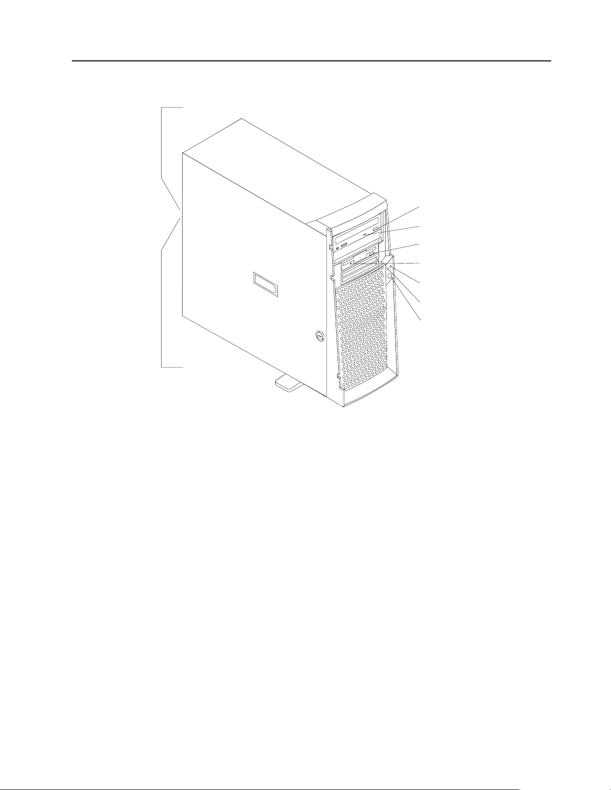
Server controls and indicators
Ethernet speed 100 Mbps
CD eject
button
CD-ROM drive
activity light
Diskette eject
button
Diskette drive
activity light
Hard disk drive
activity light
Power-on
light
Power control
button
Ethernet transmit/
receive activity
CD-ROM drive activity light: When this light is on, it indicates that the CD-ROM
drive is in use.
Diskette eject button: Push this b ut t on to install or remove a diskette from the dr ive.
Diskette drive activity light: When this light is on, it indicates that the diskette drive
is in use.
Hard disk drive activity light: When this light is on, it indicates that the hard disk
drive is in use.
Power-on light: This status indicator lights when you turn on your server.
Power control button: Press this button to man ually turn the serve r on or off.
See “I/O conne ctor locations” on page 60 for the location of the input/output (I/O)
connectors on the rear of th e se r v er.
Turning on the server
After you plug one end of the server power cord into the power supply outlet on the
rear of the server, and the other end of the power cord into an electrical outlet, the
server can start as follows:
• You can press the power control button on the front of the server to start the
server.
• If the server is turned on and a power failure occurs, the server will start
automatically when power is restored.
General information 7
Page 16

CAUTION:
The power control butto n on the device and the power switch on the powe r supply do not
turn off the el ectr ical c urr ent suppl ied to t he dev ice. The device a lso might have m ore th an
one power cord. To remove all electri cal current from the device, ensure that all power
cords are disconnected from the power source.
2
1
Turning off the server
You can turn off the server in any of the following ways:
• You can press the power control button on the front of the server. This starts an
orderly shutdown of the operating system, if this feature is supported by your
operating system, and places the server in standby mode.
Note: After tu rning off the se rver, wait at least five seconds before you press the
power control button to turn on the server again.
• You can press and hold the power control button for more than four seconds to
cause an immediate shutdown of the server and place the server in standby
mode. Y ou ca n use this feature if the operating system stops functioning.
• You can disconnect the server power cords from the electrical outlets to shut off
all power to the server.
Note: After di sconnecting the power cords, wait appr oximately 15 seconds for
your system to stop running.
8 Hard ware Ma inte nance Manual: xSer ies 200
Page 17

Diagnostics
This section provides basic troubleshooting information to help you resolve some
common pr oblems that might occur wi th the server.
If you cannot locate and correct the problem using the information in this sec tion,
refer to “Symptom-to-F RU index” on page 85 for more information.
Diagnostic tools overview
The following tools are available to help you identify and resolve hardware-related
problems:
• POST bee p cod es
The power-on self-test (POST) generates beep codes and messages to indicate
successful test completion or the det e ction of a probl e m. See “POST” for more
information.
• Diagnostic programs and error messages
The server diagnostic programs are provided on the IBM Enhanced Diagnostics
CD. These programs test the major components of the server . See “Diagnostic
programs and error messages” on page 10 for more information.
POST
When you turn on the server, it performs a series of tests to check the operation of
server components an d some of the options installed in th e se rver. This se ries of tests
is called the power-on self-test or POST.
If POST finishes without detecting any problems, the first window of the operating
system or application program appears.
Note:
1. If you have a power-on passw ord or administrator password set, you
must type the password and press Enter, when prompted, before POST
will continue.
2. A single problem might cause several error messages. When this occurs,
work to correct the cause of the first error message. After you correct the
cause of the first error message, the other error messages usuall y will no t
occur the next ti m e y ou ru n th e tes t .
POST beep code descriptions
POST generates beep codes to indicate successful completion or the detection of a
problem.
• One short beep indicates the successful completion of POST.
• More than one beep indicates that POST detected a problem. For more
information, see “Beep symptoms” on page 85“.
POST error messages
The possible types of beep codes that your system might emit are:
© Copyright IBM Corp. 2000 9
Page 18

Repeating long beeps
Indicates th at a memory error has occurred. Ensure that all DIMM s are
correctly installed.
One long beep and two short beeps
Indicates that a video err or has occurred and the BIOS cannot initialize the
video screen to display any additional i nformation. Ensure that the video
adapter is correctly installed.
For a list of POST errors, see “POST error co de s” on page 94.
Small computer system interface messages (some models)
The following table lists actions to take if you receive a SCSI error message.
Note: If the server does not have a har d disk drive, i gnore any mess age that indicates
that the BIOS is not installed.
You will get these messages only when running the SCSI Select Utility.
SCSI Messages Description
All One or more of the following might be causing the problem.
• A failing SCSI device (adapter or drive)
• An improper SCSI configuration
• Duplicate SCSI IDs in the sam e SCSI chain
• A n improperly installed SCSI terminator
• A defectiv e SCSI terminator
• A n improperly installed cable
• A defectiv e cable
Action:
Verify th a t :
• The external SCSI devices are turned on. External SCSI devices must
be turned on before the server.
• The cables for all external SCSI devices are connected correctly.
• The last d e vice in each SCSI ch ai n i s terminated p r operly.
• The SCSI devices are configured correctly.
If the above items are correct, run the diagnostic programs to obtain
additional information about the failing device.
Table 2. SCSI messages.
Diagnostic programs and error messages
The server diagnost ic p rograms are stored on the IBM Enhanced Diagnostics CD. These
programs provide the primary methods of tes ting the major components of the server.
Diagnostic error messages indicate that a problem exists; they ar e not inten ded to be
used to identify a failing part. Troubleshooting and servicing of complex problems
that are indicated by error messages should be performed by trained service
personnel.
10 Hardware Maintenance Manual: xSeries 200
Page 19

Somet i m e s th e f i rs t e rro r to occur caus e s addition al errors. In th is ca s e , th e server
displays more than one error message. Always follow the suggested action
instructions for the first error message that appears.
The following sections contain the error codes that might appear in the detailed test
log and summary log when running the diagnostic programs.
The error code format is as follows:
fff-ttt-iii-date-cc-text message
where:
fff is the thre e -digit fun ction code that in di cates the function being
ttt is the thre e -digit failure code that indicates the exact test failu re that
iii is the thr e e-digit device ID.
date is the date that the diagnostic test was run and the error recorded.
cc is the check digit that is used to verify the validity of the information.
text message is the diagnostic message that indicates the rea son for the problem .
Text messages
tested when the error occurred. For example, function c od e 089 is for
the microprocessor.
was encou ntered.
The diagnostic text message format is as follows:
Function Name: Result (test specific string)
where:
Func tion Name
is the name of the function being tested when the error occurred. This
corresponds to the function code (fff) given in the previous list.
Result can be one of the fo llowing:
Passed This result occurs when th e di agnostic test completes without any
errors.
Failed This re sult occurs when th e di agnostic tes t di scovers an error.
User Aborted
This result occurs when you stop the diagnostic test before it is
complete.
Not Applicable
This result occurs when you specify a diagnosti c test for a device that
is not present.
Aborted This result occurs when the test could not proceed because of the
server configuration.
Warning This result occurs when a possible problem is reported during the
diagnosti c test, such as whe n a device that is to be tested is not
installed.
Te st Spec i fi c Stri ng
This is additional informa tion th at is used to analyz e the problem.
Diagnostics 11
Page 20

Starting the diagnostic programs
The IBM Enhanced Diagnostics programs will isolate your server hardware from
software that you have installed on your hard disk drive. The programs run
independently of the operating system, and must be run either from the CD or diskette.
This method of testing is generally used when other methods are not accessible or
have not been successful in isolating a problem suspected to be hardware related.
An IBM Enhanced Diagnostics CD comes with the server. You can also download the
latest image of the diagnostics from the World Wide Web at
http://www.ibm.com/pc/support.
Using the diagnostics CD
To start the IBM Enhanced Diagnostics using the CD, do the following:
1. Turn off your server and any peripheral devices.
2. Turn on all attached devices; then, turn your server on.
3. When you see Press F1 For Configuration/Setup, press the F1 key.
4. When the Configuration/Setup Utility menu appears, select Start Options.
5. From the Start Options menu, select Startup Sequence.
6. Note the device selected as the First Startup Device. Later, you must restore this
setting.
7. Select CD-ROM as the First Startup Device.
8. Press Esc two time s to return to the Configurati on/Setup Util ity menu.
9. Place the IBM Enhanced Diagnostics CD in the CD - ROM dr ive.
10. Select Save & Exit Setup and follow the p rompts. The diagnostics will load.
Follow the instructions on the screen to run the diagnostics.
Important
When you finish running the diagnostics and utilities, remove the CD from the CD-ROM
drive and turn off the server. You must restore the First Startup Device to the original setting.
Use steps 2 through 8 of this procedure to do this.
Downloading the diagnostics program
Do the following to download the latest image of the IBM Enhanced Diagnostics from
the World Wide Web and cr eate a startable Enha nced Diagnos t ics dis kette:
1. Go to the following World Wide Web site: http://www.ibm.com/pc/support/
2. Download the diagnostics file for your server to a hard disk drive directory (not
to a dis ke tte).
3. Go to a DOS prompt and change to the directory where the file was downloaded.
4. Insert a blank high-density diskette in diskette drive A.
5. Type in the following, and then press Enter: filename a:
where filename is the name of the file you downloaded from the Web.
The downloaded file is self-extracting and will be copied to the diskette. When the
copy completes, you have a startable IBM Enhanced Diagnostics diskette.
12 Hardware Maintenance Manual: xSeries 200
Page 21

Using the diagnostic diskette
Do the following to start the IBM Enhanced Diagnostics using the diagnostics
diskette, do the fol lowing:
1. Turn off your server and any peripheral devices.
2. Insert the IBM Enhanced Diag nostics diske tte into the diskette drive.
3. Turn on all attached devices; then, turn on the server.
4. Follow the instructions on the screen.
5. Place the IBM Enhanced Diagnostics CD in the CD-ROM drive. The diagnostics will
load. Follow the instructions on the screen to run the diagnosti cs.
When the tests have completed, you can view the Test Log by selectin g Utility from
the top of the screen.
If the hardware checks out OK but the problem persists during normal server
operations, a software error might be the cause. If you suspect a software problem,
refer to the information that comes with the software package.
Viewing the test log
The test log records data about syste m f a ilures and othe r pertinent i nformation. Th e
test log will not contain any information until after the diagnostic program has run.
Note: If you already are running the diagnostic programs, begin with step 4.
1. Insert the IBM Enhanced Diagnostics CD.
2. Turn on the system and watch the screen.
If the syst e m is on, shut down your operating system and restart the system.
3. If a power-on password is set, the system prompts you for it. Type in the
appropriate password; then, press Enter.
4. Run the appropriate diagnostics program and when the Diagnostic Programs
screen appears, select Utility.
5. Select View Test Log from the list that appears; then, foll ow the instr uctions on
the screen.
6. You ca n save the test log to a file on a diskette or to your hard di sk drive.
Note: The syst e m mai ntains the test -log data while th e system is power e d on.
When you turn off the power to the server, the test log is cleared.
Diagnostic error message tables
For descriptions of the error messages that might appear when you run the diagnostic
programs, see “Diagnost ic error codes” on page 89. If diagnostic error messages
appear that are not listed in those tables, make sure that the server has the latest levels
of BIOS, Advance d System Managemen t P rocessor, ServeRAID, and diagnostics
microcode installed.
Power checkout
Power problems can b e difficu lt to trou bleshoot. For instance, a short circui t can exist
anywhere on any of the power distributio n busses. Usually a short circuit will cause
the power su b s ystem to shut d own because of an overcurrent conditi o n.
A general procedure for troubleshooting power problems is as follows:
Diagnostics 13
Page 22
1. Power off the server and disconnect the AC cord(s).
2. Check for loose cables in the power subsystem. Also check for short circuits, for
3. Remove adapters and disconnect the cables and power connector s to al l internal
4. R econnect the AC cord and power on the server. If the server powers up
To use this method it is important to know the minimum configuration required for a
server to power up (see page 100).
Recovering BIOS
If the BI O S has bec ome c orr up t ed, su ch as fr om a pow er f ai lu r e du ri n g a fl ash up dat e,
you can recover the BIOS using the boot block jumper and a BIOS flash diskette. The
boot block jumper selects which of two BIOS images to use. In the normal position,
the jumper will be installed on pins 2 and 3. In the alternate block position, the jumper
will be installed on pins 1 and 2.
Note: You can obtain a BIOS flash diskette fr om one of the following sources:
instance if there is a loose screw causing a short circuit on a circuit board.
and external devices until server is at minimum configuration required for power
on (see "Minimum operating requirements" on page 100).
successfully, replace adapters and devices one at a time until the problem is
isolated. If server does not power up from minimal configuration, replace FRUs
of minimal configuration one at a time until the problem is isolated.
• Use the ServerGuide program to make a BIOS flash diskette.
• Download files to make a BIOS flash dis kette from the World Wide Web.
Go to http://www.ibm.com/support/ select IBM System Support, and
then make the selections for your system.
Do the following to recover the BIOS:
1. Turn off the server and periphera l devic e s and disconnect all external cables and
power cords; then, r emo ve t he side cov er, see “Removing the side cover” on page
40.
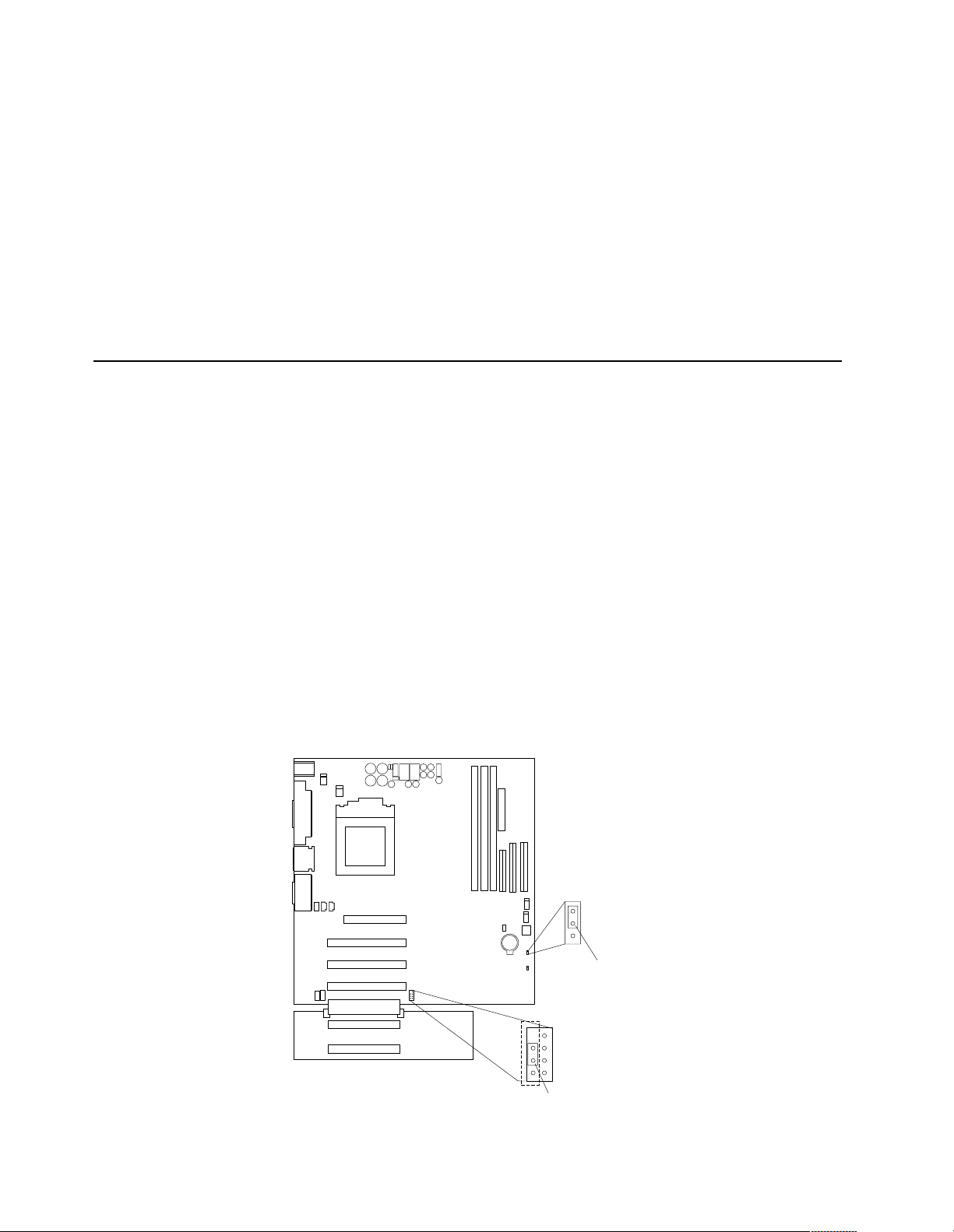
2. Locate jumper JROM1 on the system board.
1
2
3
CMOS jumper
(JBAT1)
3
2
1
p
14 Hardware Maintenance Manual: xSeries 200
Page 23

3. Move the JROM1 jumper to the alternate position (pins 1 and 2) to enable the
BIOS recovery mode.
4. Reinstall the side cove r, see “Installing the cover” on page 59.
5. Reconnect all external cables an d pow er cords and turn on the peripheral devices.
6. Insert the BIOS flash diskette in the diskette drive.
7. Restart the server. The BIOS begins the power-on self-test.
8. Select 1 - Update POST/BIOS from the menu that contains various flash (update)
options.
9. When prompted as to whether you want to save the current code to a diskette,
select N.
10. When prompted to choose a language, select a language (from 0 to 7) and press
Enter to accept your choice.
11. Do not restart your server at this time.
12. Remove the BIOS flash diskette from the diskette drive.
13. Turn off the server and peripheral devices and disconnect all external cables and
power cords; then, r emo ve t he side cov er, see “Removing the side cover” on page
40.
14. Move the JROM1 ju mper to the normal position (pin s 2 and 3) to return to normal
startup mode.
15. Reinstall the side cover, see “Installing the cover” on page 59.
16. Reconnect all external cables and power cords and turn on the peripheral devices.
17. Restart the se rver, which should start up normally.
Clearing CMOS
If you need to erase configuration information, you must move the CMOS jumper. See
the illustration in “Recovering BIOS” on page 14 for the location of the CMOS jumper.
The default position is a jumper installed on pins 1 and 2. Before you change the
position of this jumper , you must turn off the server and peripheral devices, and
disconnect all external cables and power cords . Remove the cover and then move the
jumper to pins 2 and 3.
After moving the jumper, wait at least 5 minutes for the CMOS information to clear.
Changing the position of this jumper erases all configuration and setup information,
including the power-on and administrator passwords. Therefore, you must
reconfigure the server after clearing CMOS memory (see “Ch apter . Configuring th e
server,” on page 29). If possible, record your server configuration information before
moving the CMOS jumper.
After you clear the CMOS information, move the jumper back to its normal position
(pins 1 and 2). Reconnect the external cables and power cords; then, turn on the
peripheral devices and the server.
Replacing the battery
When replacing the battery, you must replace it with a lithium battery of the same
type from the same manufacturer. To avoid possible danger, read and follow the
safety statement below.
Diagnostics 15
Page 24
To order repl acement batteries, call 1-800 -772-2227 within the United States, and 1800-465-7999 or 1-80 0-465- 6666 withi n Cana da. Ou tside t he U.S. and Canada, call your
IBM reseller or IBM marketing representative.
Note: After you replace the battery, you must reconfigure your system and reset the
system date and time.
CAUTION:
When replacing the battery, use only IBM Part Number 33F8354 or an equivalent
type battery recommended by the manufacturer. If your server has a module
containing a lithium battery, replace it only with the same module type made by
the same manufacturer. The battery contains lithium and can explode if not
properly used, handled, or disposed of.
Do not:
• Throw or immerse into water
• Heat to more than 100°C (212°F)
• Repair or disassemble
Dispose of the battery as required by local ordinances or regulations.
Do the following to replace the battery:
1. Read “Before you begin” on page 38, and follow any special handling and
installation instructions supplied with the replacement battery.
2. Turn off the server and periphera l devic e s and disconnect all external cables and
power cords; then, remove the server cover.
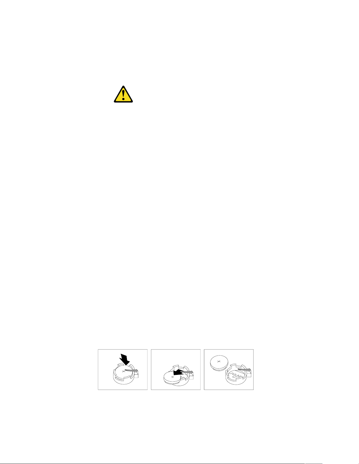
3. Remove the battery:
a. Use one finger to lift the battery clip over the battery.
b. Use one finger to slightly slide the battery out from its socket. The spring
mechanism will push the battery out toward you as you slide it from the
socket.
c. Use your thumb and index finger to pull the battery from under the battery
clip.
d. Ensure that the battery clip is touching the base of the battery socket by
pressing gently on the clip.
4. Do the following to insert the new battery:
a. Tilt the battery so that you can insert it into the socket under the battery clip.
b. As you slide it under the battery clip, press the battery down into the socket.
16 Hardware Maintenance Manual: xSeries 200
Page 25

5. R einstall the server cover and connect the cables.
6. Turn on the se rver.
7. Start the Configuration/Setup Utility program and set configuration parameters.
• Set the server date and time.
• Set the power-on password.
• Reconfigure your server.
Temperat ur e checkou t
Proper cooling of the server is important for proper operation and server reliability.
For a typical xSeries ser ve r, you should make sure:
• Each of the drive bays has either a drive or a filler panel installed
• Each of the power supply bays has either a power supply or a filler panel installed
• The server cover is in place during normal operation
• There is at l east 50 mm (2 inches) of ventilated space at the sides of t he se rv er and
100 mm (4 inches) at the rear of the server
• The server cover is removed for no longer than 30 minutes while the server is
operating
• The processor housing cover covering the proc essor and memory area is r emoved
for no longer that ten minutes while the server is operating
• A removed hot-swap drive is replaced within two minutes of removal
• Cables for optional adapters are routed according to the instructions provided
with the adapters (ensure that cables are not restricting air flow)
• The fans are operati ng correctly and the air flow is good
• A failed fan is replaced within 48 hours
In addition, ensure that the environmental specifi cat i on s for the server are met. See
“Features and specifications” on page 3“Features and specifications” on page 3.
Note: The speed of the fans will increase if:
• One fan fails.
• Ambient temperature gets too high.
Diagnosing errors
To find solutions to problems that have definite symptoms, see “Error symp t o ms” on
page 92.
If you cannot find the problem there, go to “Starting the diagnost ic programs” on
page 12 to test the se rver.
Diagnostics 17
Page 26

If you ha ve jus t ad de d new soft ware or a n ew opt ion and the se rver i s not wo rkin g, d o
the following before using the error symptoms table:
• Remove the software or dev ice that you just added.
• Run the diagnostic tests to determine if the serve r is running correctly.
• Reinstall the new softwa re or new device.
Troubleshooting the Ethernet controller
This section provides troubleshooting information for problems that might occur with
the 10/100 Mbps Ethernet controller.
Network connection problems
If the Ethernet controller ca nnot connec t to the network, check the following:
• Make sure that the cable is installed correctly.
The network cable must be securely attached at all connections. If the cable is
attached but the problem persists, try a different cable.
If you set the Ethernet contr oll er to operate at 100 Mbps, you must use Cate gory 5
cabling.
If you directly connect two workstations (without a hub), or if you are not using a
hub with X ports, use a crossover cable.
Note: To determine whether a hub has an X port, check the port label. If the label
contains an X, the hub has an X port.
• Determine if the hub suppo rts auto-negotiation. If not, try configuring the
integrated Ethernet controller manually to match the speed and duplex mode of
the hub.
• Check the LAN activity light (if available) on the front of the server. The LAN
activity light illuminates when the Ethernet controller sends or receives data over
the Ethernet network. If the LAN activity light is off, make sure that the hub and
network are operating and that the correct device drivers are loaded.
• Make sure that you are using the correct device drivers, supplied with your
server.
• Check for operating server-specific causes for the problem.
• Make sure that the device drivers on the client and server are using the same
protocol.
• Test the Ethernet controller.
The way you test the Ethernet controller depends on which operating system you
are using (see the Ethernet controller device driver README file).
Etherne t controller troubleshooting chart
You can use the following troubleshooting chart to fi nd sol u ti ons to 10/100 Mbps
Ethernet controller problems that have definable symptoms.
18 Hardware Maintenance Manual: xSeries 200
Page 27

Ethernet controller
problem
Suggested Action
The server stops
running when loading
device drivers.
The LAN activity light
(when available ) does
not light.
The PCI BIOS interrupt settings are incorrect.
Check the following:
• D ete rm in e if the IRQ sett ing assi gned to the Ether net co ntrolle r
is also assigned to another device in the Configuration/Setup
Utility program.
Although interrupt sharing is allowed for PCI devices, some
devices do not functi on well wh en the y share an interr up t with
a dissimilar PCI device. Try changing the IRQ assigned to the
Ethernet controller or the other device. For exa mple, for
NetWare Ve rs ions 3 and 4 it is recommended that disk
controllers not share interrupts with LAN controllers.
• Make sure that you are using the most recent device driv er
available from the World Wide Web.
• Run the network diagnostic program.
If the problem remains, call for service.
Check the following:
• Make sure that you have loaded the network device drivers.
• The network might be idle. Try sending data from this
workstation.
• Run diagnostics on the LEDs.
• The function of this LED can be changed by device driver load
parameters. If necessary, remove any LED parameter settings
when you load the device drivers.
Data is incorrect or
sporadic.
Check the following:
• Make sure that you are using Category 5 cabling when
operating the server at 100 Mbps.
• Make sure that the cables do not run close to noise-inducing
sources like fluorescent lights.
The Ethernet
controller stopped
working when
another adapter was
added to the server.
Check the following:
• Make sure that the cable is connected to the Ethernet controller.
• Make sure that your PCI server BIOS is current.
• Reseat the adapter.
• Determine if the IRQ setting assigned to the Ethernet adapter is
also assigne d to another device in the Con fi guration/Setu p
Utility program.
Although interrupt sharing is allowed for PCI devices, some
devices do not functi on well wh en the y share an interr up t with
a dissimilar PCI device. Try changing the IRQ assigned to the
Ethernet adapter or the other device.
If the problem remains, call for service.
Table 3. Ethernet troubleshooting cha rt.
Diagnostics 19
Page 28

Ethernet controller
problem
The Ethernet
controller stopped
working w ith ou t
apparent cause.
Check the following:
• Run diagnostics for the Ethernet controller.
• Try a different connector on the hub.
• Reinstall the device drivers. Refer to your operating system
documentation and to the ServerGuide information.
If the problem remains, call for service.
Table 3. Ethernet troubleshooting cha rt.
Suggested Action
20 Hardware Maintenance Manual: xSeries 200
Page 29

Ethernet controller messages
The integrated Ethernet controller might display messages from the following device
drivers:
• Novell NetWare
• Network driver interface specification (NDIS) adapter for level 4.0 (Windows NT)
Novell NetWare or IntraNetWare system ODI driver teaming messages
This section provides explanations of the error messages for the Novell NetWare or
IntraNe tWare system ODI driver, and suggested actions to resolve eac h problem.
™
or IntraNetWar e syst em open data-link interface (ODI)
Diagnostics 21
Page 30

Message Description
Couldn’t allocate resources. Explanation: An unknown error has occurred when trying to
allocate needed resources for the AFT Module.
Action:
• Check the server configuration. If the problem persists,
contact your net work supplier.
• Verify that the Ether net contr oller is enabled. If the
Ethernet controller is enabled , ru n the diagnost ic
programs.
AFT group for prima r y
adapter in slot nnn al ready
exists.
Error locating device control
table (DCT ) ad d resses in
internal table. Make sure that
you have loaded LAN
drivers after loading
AFT.NLM.
Insufficient number of
arguments specified.
Duplicate slot numbers
detected.
’xxx’ is not supported for
AFT team.
Explanation: An attempt was made to rebin d an ada pte r
already in an AFT group.
Action: Check the AFT slot numbers for existing AFT teams.
If the problem per s is ts, co nt ac t your network supplie r.
Explanation: The bind command was entered prior to
loading the device driver. The device driver must be loaded
after loading AFT.NLM, but before any bind command can be
issued.
Action: Load the driver for the supported adapter and try
loading the AF T module again. If the problem persists,
contact your net work supplier.
Explanation: The appropriate or expected number of
parameters was not enter ed in a command.
Action: Check the parameters required for the given
command . If the probl em persi sts , con ta ct you r ne twor k
supplier.
Explanation: An attempt has been made to bind the same slot
number more than once.
Action: Check the slot numbers entered during the bind.
Adapter slot numbers must be valid and unique. If the
problem persists, contact your network supplier.
Explanation: A bind command has been is sued fo r adapters
not supported by AFT.NLM.
Action: Make sure that you attempt to bind only adapters
supported by AFT.NLM.
Primary and Secondary
adapters do not match. AFT
group is not created.
Requested number of
Secondary cards are not
found.
Failed to create AFT group.
Make sure that the drive rs
for suppor t e d ad apte rs are
loaded, primary ada pte r i s
bound to protocols, and
secondary adapter is not
bound t o a ny protocols.
Explanation: A bind command was entered for an adapter
team that is a combination of server and client adapters. An
AF T tea m must be a group i ng of the same classification of
adapter.
Action: V e rify that all the adap ters bound in a team are of the
same classification.
Explanation: The number of adapters specified in the bind
command could not be located.
Action: Verify the numbers and slot locations of the adapters
to be bound. If the problem persists, contact your network
supplier.
Explanation: Binding of protocol failed. Protocol is ei ther not
bound to any adapter or is bound to more than one adapter in
the group.
Action: Ens u re that t he prot oc ol i s bou nd to on l y ad ap ter in
an AFT team.
Table 4. NetWare driver messages for the Ethernet controller.
22 Hardware Maintenance Manual: xSeries 200
Page 31

Message Description
Erro r i dent if ying s lot
numbers for the specified
board names.
Can’t unbind specified slot
from AFT group. Make sure
that the slot you specified is
for the primary adapt e r in an
AFT group.
LAN adapter at slot nnnn
(Port 0xaa) failed to reset.
Check the state of the
adapter.
AFT is not supported on this
version of NetWare™.
Failed to allocate resources
tags.
Explanation: The mapping between the board name entered
and the slot number for an adapter could not be established.
Action: Check the board name for the adapter before issuing
the bind command. If the problem persists, contact your
network supplier.
Explanation: The number entered in the unbind command
was not the primary adap ter in an AFT group.
Action: Reissue the unbind command and specify the slot
number for the primary adapter.
Explanation: The adapter that you specified could not be
initialized.
Action:
1. Load the driver for the supported adapter.
2. Check that the adapter is seated prop erly in the sl ot and
try loading the AFT module again.
If the problem per s is ts, co nt ac t your network supplie r.
Explanation: The NetWare on your server is not a version
supported by AFT.
Action: Load and bind AFT only on supported versions of
NetWare (currently versi on 4.11 and above).
Explanation: An unknown error has occurred when trying to
allocate needed resources for the AFT module.
Action: Check server configuration. If the problem persists,
contact your net work supplier.
Please unload all LAN
drivers before unloading
AFT.NLM.
Explanation: An attempt was ma de to unloa d the A FT.NLM
module before unloading the adapter driver.
Action: Unload the adapter driver before unloading the AFT
module.
Table 4. NetWare driver messages for the Ethernet controller.
NDIS 4.0 (Windows NT) driver messages
This section contains t he erro r messages for the NDIS 4.0 driv ers. The explan ation and
recommended action are included with each message.
Diagnostics 23
Page 32

Error code
(hex)
0x00 Explanation: The driver could not register the specified interrup t .
Action: Using the Configuration/Setup Utility program, make sure that a
PCI interrupt is assigned to your Ethernet card, and that Ethernet is enabled.
0x01 Explanation: One of the PCI cards did not get the required resources.
Action: Using the Configuration/Setup Utility program, make sure that a
PCI interrupt is assigned to your Ethernet card, and that Ethernet is enabled.
0x02 Explanation: Bad node address (multicast address).
Action: Make sure the locally administered address is valid, if one is
specified. The address can no t be a multic ast address.
0x03 Explanation: Failed self-test.
Action: Make sure a cable is attached to the Ethernet connector. If the
problem persists, call for service.
0x0D Explanation: Could not allocate enough memory for transmit queues.
Action:
1. From the Windows NT desktop, se lect Start
Networks
2. Select your IBM Ethernet adapter from the list.
3. Select Properties
4. Lower the resource values that apply to the transmit queue.
0x0E Explanation: Could not allocate enough memory for receive queue.
Action:
1. From the Windows NT desktop, se lect Start
g
Networks gAdapters.
2. Select your IBM Ethernet adapter from the list.
3. Select Properties
4. Lower the resource values that apply to the receive queue.
g
Adapters.
g
Advanced.
g
Advanced.
Description
g
Control Panel g
g
Control Panel
0x0F Explanation: Could not allocate enough memory for other structures.
Action:
1. From the Windows NT desktop, se lect Start
Networks
2. Select your IBM Ethernet adapter from the list.
3. Select Properties
4. Lower the value for the resource named in the message.
0x10 Explanation: Did not find any Ethernet co ntrollers.
Action: Using the Configuration/Setup Utility program, make sure that
Ethernet is enabled.
0x11 Explanation: Multiple Ethernet controllers found, but none matched the
required ID.
Action: Using the Configuration/Setup Utility program, make sure that
Ethernet is enabled.
0x13 Explanation: Did not find any Ethernet controllers that matched the required
subven/subdev.
Action: Using the Configuration/Setup Utility program, make sure that
Ethernet is enabled.
g
Adapters.
g
Advanced.
g
Control Panel g
Table 5. NDIS (Windows NT or Windows 2000) driver messages for the Ethernet
controller.
24 Hardware Maintenance Manual: xSeries 200
Page 33

Error code
(hex)
0x16 Explanation: Single adapter found, but multiple instances tried to load.
Action: Using the Configuration/Setup Utility program, make sure that
Ethernet is enab l e d, and that the slot contai ning the IBM xSeries 200 10/100
Ethernet Adapter or the IBM 10/100 Etherjet PCI adapter is enabled.
0x17 Explanation: Slot parameter not specified in the registry.
Action: Remove the adapter driver and reinstall it. If the problem persists,
cal l for service.
Description
All other 4character
hexadecimal
codes
Action: Call for service.
Table 5. NDIS (Windows NT or Windows 2000) driver messages for the Ethernet
controller.
Diagnostics 25
Page 34

Ethernet teaming messages:
This section displays the messages associated with Ethernet teaming.
26 Hardware Maintenance Manual: xSeries 200
Page 35

Even t ID Type Desc ri p tio n
01 Error Explanation: T eam name and physical adapter name are
the same. This is an invalid configuration.
Action: Reconfigure the adapter team by double-clicking
the PROSet icon in the control panel.
02 Error Explanation: Unable to allocate required resources.
Action: Free some memory resources and restart.
03 Error Explanation: Unable to read required registry parameters.
Action: Reconfigure the adapter team by double-clicking
the PROSet icon in the control panel.
04 Error Explanation: Unable to bind to physical adapter.
Action: Reconfigure the adapter team by double-clicking
the PROSet icon in the control panel.
05 Error Explanation: Unable to initialize an adapter team.
Action: Reconfigure the adapter team by double-clicking
the PROSet icon in the control panel.
06 Informational Explanation: Team nn. Primary adapter is initialized.
Action: None.
07 Informational Explanation: Team nn. Secondary adapter is initialized.
Action: None.
08 Informational Explanation: Team nn. V irtual adapter or Team is
initialized.
Action: None.
09 Informational Explanation: Team nn. Primary adapter is switching over.
Action: None.
10 Warning Explanation: Team nn. Adapter link down.
Action: Make sure the adapter is functioning properly.
11 Informational Explanation: Team nn. Secondary adapter took over.
Action: None.
12 Warning Explanation: Team nn. Secondary adapter is deactivated
from th e T eam.
Action: Make sure the secondary adapter is functio ning
properly and t hat t he adapt er c able is s ecur ely co nnec ted t o
the LAN.
13 Informational Explanation: Team nn. Secondary adapte r has r ejoi ned the
Team.
Action: None.
14 Informational Explanation: Team nn. Secondary adapter link is up.
Action: None.
15 Error Explanation: Team nn. The last adapter has lost its link.
Network connection has been lost.
Action: Shut down the server and replace the adapters;
then, restart the server to reestablish the connection.
16 Informational Explanation: Team nn. An adapter has reestablish e d the
link. Network connection has been restored.
Action: None.
Table 6. NDIS (Windows NT or Windows 2000) driver teaming messages for the
Ethernet controller.
Diagnostics 27
Page 36

Even t ID Type Desc ri p tio n
17 Informational Explanation: Team nn. Preferre d pri mary adap ter has been
detected.
Action: None.
18 Informational Explanation: Team nn. Preferred secondary adapter has
been detected.
Action: None.
19 Informational Explanation: Team nn. Prefe rre d prim ary ada pter took
over.
Action: None.
20 Informational Explanation: Team nn. Preferred secondary adapter took
over.
Action: None.
21 Warning Explanation: Team nn. Primary adapter does not sense any
Probe s . Possibl e reason: partitioned Team.
Action: Make sure the cables of the adapter team are
connected to the same LAN segment. Reconfigure the team
if necessary.
Table 6. NDIS (Windows NT or Windows 2000) driver teaming messages for the
Ethernet controller.
28 Hardware Maintenance Manual: xSeries 200
Page 37

Configuring the server
The following configuration programs ar e pro vided with the server:
• Configuration/Setup Utility
The Configura tion /S etup Utilit y program is part of the BIOS code that comes
with the server. You can use this program to configure serial- and parallelconnector assignments, change the drive startup sequenc e, set the date and time,
and set passwords. See “Using the Configuration/Setup Utility program” for
more information.
• SCSISelect Utility
With the SCSIS e le ct Uti l i ty p rogram, you ca n co n fi gu re the devices tha t a re
attached to the op tio nal SCSI adapter. Use this program to change defa ult value s,
resolve configuration conflicts, and perform a low-level format on a SCSI hard
disk drive. See “Using the SCSISelect utility program (some models)” on page 32
for more information.
• ServeRAID programs
The ServeRAID programs come with the optional ServeRAID adapters and with
server models that have a ServeRAID adapte r pr ei nstalled. If a ServeRAID
adapter has been installed in the server, you must use the ServeRAID
configuration program to define and configure the dis k-array s ubsyste m before
you install the operating system.
• ServerGuide CDs
The ServerGuide CDs include softwa re setup an d installa t io n tools spec if ically
designed for IBM 200 servers. You can use these CDs during the initial
installation of the server to configure the server hardware and simplify the NOS
installation. The ServerGuid e CDs also cont ain a collec tion of ap plicat io n
programs, which you can install after the server is up and running.
Using the Configuration/Setup Utility program
This section provides the instructions for starting the Configuration/Setup Utility
program and also provides descri ptions of the menu choices that are available.
Starting the Configuration/Setup Utility program
Complete the following steps to start the Configuration/Setup Utility program:
1. Turn on the server and watch the monitor screen.
2. When the message Press F1 for Configuration/Setup appears, press F1.
3. Follow the instructions that app ear on the screen.
Choices avail able from the Configuration/Setup main menu
From the Configuration/S etup Ut ility main menu, you can select settings that you
want to change. The Configuration/Setup Utility main menu is similar to the
following illustration:
© Copyright IBM Corp. 2000 29
Page 38

CMOS Setup Utility - Copyright (c) 1984 - 2000 Award Software
Configuration/Setup Utility
Select Option:
System Summary
Product Data
Devices & I/O Ports
Start Options
Frequency Control
Date and Time
System Security
Advanced Setup
Power Management Setup
Save & Exit Setup
Load Optimized Defaults
Exit Without Saving
Move Enter: Select F1: General Help
F10: Save ESC: Exit
Note:
1. You can press F1 to display help information for a selected menu item.
2. The choices on some menus might diffe r sl ightly from the ones that are
described in this book, depending on the BIOS version in the server.
Descriptions of the choices that are available from the main menu are as follows:
• System summary
Select this choice to display configuration information. This includes the type and
speed of the microprocess ors and the amount of memory that is installed.
Changes that you make to configuration settings appear on this summary screen.
You cannot edit the fields.
This choice appears on both the full and limited Configuration/Setup Utility
menus.
• Product data
Select this choice to view system information, such as the machine type and
model, the server serial number, and the revision level or issue date of the BIOS
stored in the flash electronicall y eras abl e programmable read-only memory
(EEPROM).
• Devices and I/O port s
Select t his choic e to v ie w or chan ge th e as sig nmen ts fo r de vice s and input /out put
ports. This choice appears only on the full Configuration/Setup Utility main
menu.
• Start Options
Select thi s choice to view or ch ange the start opti on s. Start options tak e e ffect
when you start the server.
You can select keyboard operating characteristics, such as the keyboard speed.
You also can specify whether the server starts with the keyboard number lock on
or off.
The server uses a startup sequence to determine the device from which the
operating system starts. For example, you can define a startup sequence that
checks for a startable diskette in the diskette drive, then checks the hard disk
drive in bay 5, and then checks a network adapter.
30 Hardware Maintenance Manual: xSeries 200
Page 39

You can enable a virus-warning test that checks for changes in the master boot
record at startup. You also can choose to r un POST in the quick mode, and read
the microproce ssor serial number.
• Frequency Control
Select this choice to enable or disable the auto-detect DIMM/PCI clock.
• Date and Time
Select thi s choice to set the system date and time.
The system time is in a 24-hour format: hour:minute:second.
Note: You may also set the date and time using the procedures provided on the
ServerGuide CDs.
• System Security
Select this choice to set a power-on or an a dmi nistrator password.
See “Using passwords” on page 32 for more information.
• Advanced Setup
Select this choice to change values for advanced hardware features, such as Cache
Control and PCI configuration.
A message appears above the choices on this menu to alert you that the system
might malfunction if these options are configured incorrectly. Follow the
instructions on the screen carefully.
— Cache Control
Select this choice to enable or disable th e microprocessor cache.
Attention: Do not make changes to the Cache Control unless directed to do
so by an IBM authorized service representative.
— ROM Shadowing
Select thi s choice to enabl e or disable the state of a ROM shadowing.
— Chipset Feature
Select this choice to modify settings that control features of the core chip set
on the syste m board.
Attention: Do not m a k e changes to the Ch ipset Feature unless directed to d o
so by IB M .
— Memory Settings
If a memory error i s detected du ring POST or me mory configuration, the
serve r can automatically disa ble the fai ling memory bank and continue
operat ing with reduced memory capacity. If this occurs, you must manually
enable the memory bank after the problem is corrected. Select Memory
Settings from the Advanced Setup menu, use the arrow keys to highlight the
bank that you want to enable; then, use the arrow keys to select Enable.
• Power Manag em e n t Setup
Select thi s choice to enable or disable syste m p owe r savings.
• Save and Exit Setup
Select thi s choice to save th e cu stomized settin gs.
• Load Optimized Defaults
Select thi s choice to discard changes and r e store the factory settings.
• Exit Without Saving
Select this choice if you want to exit without saving changes, or if no changes have
been made.
Configuring the server 31
Page 40

Using passwords
The System Security choice appears only on the full Configuration/Setup Utility
menu. After you select this choice, you can set a power-on password or an
administrator password.
You can use any combination of up to seven characters (A–Z, a–z, and 0–9) for your
power-on password. Keep a record of your password in a secure place. If you forget
the power-on password, you can regain access to the server through either of the
following methods:
• Start the Configuration/Setup Utility program and change the power-on
password.
• Change the jumper position on the CMOS jumper as described in “Clearing
CMOS” on page 15.
• If both a power-on and administrator password are set, you can type either
password at the password prom pt that appears as you start your computer.
However, if you want to change any settings in the Configuration/Setup Utility
program, you must type your administrator password at the password prompt
that appears when you try to access the Configuration/Setup Utility program. If you
type your power-on password at this prompt, you will be able to view limited
information in the Configuration/Setup Utility program, but you will not be able
to change any settings.
Using the SCSISelect utility program (some models)
SCSISelect is a built-in, menu-driven configuration utility program that you can use
to:
• View the default SCSI IDs
• Locate and correct configuration conflicts
The following sectio ns provide the instructio ns for starting the SCS ISe lect U tility
program and descriptions of the menu choices that are available.
Note: If the server has a redundant arrays of independent disks (RAID) adapter
installed, use the configuration method that is supplied with the RAID adapter
to view or change SCSI setting s for attached devices.
32 Hardware Maintenance Manual: xSeries 200
Page 41

Star tin g the SCSI S ele ct ut ilit y program
Complete the following steps to start the SCSISelect Utility program:
1. Turn on the se rver.
2. When the <<< Press <CTRL><A> for SCSISelect™ Utility! >>> prompt appears,
press Ctrl+A.
3. When the Would you like to configure the host adapter or run the SCSI
disk utility? question appears, make your selection and press Enter.
4. Use the arrow keys to select a choice from the menu.
• Press Esc to exit the SCSI Select Utility program.
• Pres s the F5 key to switch between color and mon o chrome modes (if you r
monitor permits).
5. Follow the instructions on the screen to change the settings of the selected items;
then, press Enter.
Choices available from the SCSISelect menu
The following choices appear on the SCSISelect Utility menu:
• Configure/View Host Adapter Settings
Select this choice to view or change the SCSI controller settings. To reset the SCSI
controller to its default values, press F6; then, follow the on-screen instructions.
You can view or change the following controller settings:
— Host Adapter SCSI ID
Select this choice to view the SCSI controller identification (ID), which is
usually 7.
— SCSI Par ity Checking
Select this choice to view the assigned value of Enabled.
— Host Adapter SCSI Termination
Select this choice to view the assigned value of Automatic.
— Boot Device Options
Select this choic e t o configur e startabl e-devic e parameters . Be fore you can
make updates, you must know the ID of the device whose parameters you
want to con f igure.
— SCSI Device Configuration
Select this choice to configure SCSI-device parameters. Before you can make
updates , you must know the ID of th e device whose parameters you wan t to
configure.
Note: The Maximum Sync Transfer Rate is the transfer rate for Ultra SCSI
devices.
– The transfer rate for Ultra 160 low voltage differential (LVD)
devices is 160.0 Mbps.
– The transfer rate for Ultra2 SCSI LVD devices is 80.0 Mbps.
– The transfer rate for Fast SCSI devices is 20.0 Mbps.
— Advanced Confi gurat ion Options
Select this choice to view or change the settings for advanced configuration
options. These options include support for large hard disk drives and
support for drives with UltraSCSI speeds.
Configuring the server 33
Page 42

• SCSI Disk Utilities
Select this choice to view the SCSI IDs that are assigned to each device or to
format a SCSI device.
To use th e utilit y program , select a driv e from the list. Read the on-screen
instructions carefully before making a selection.
Note: If you press Ctrl+A before the selected drives are ready, an Unexpected
SCSI Command Failure screen might appear. Restart the server and watch
the SCSISelect messages as each dri ve starts . After th e drive that you wan t
to view or format starts, press Ctrl+A.
34 Hardware Maintenance Manual: xSeries 200
Page 43

Installing options
This chapter provides instructions to help install options to the server. For a list of
supported options for the server, see the ServerProven™ list at
http://www.pc.ibm.com/compat
Expanded view of the xSeries 200
Note: The illustrations in this document might differ slightly from your hardware.
The followin g illust rat io n show s the m ajor com p o nent s of the ser ver.
Intrusion switch
Adapter retaining
bracket
Memory modules
Microprocessor
Support bracket assembly
Cover
System and PCI extender board
EMC shie ld
Drive cage
Adapter support bracket
Filler
panel
Front door
The illustration s in the follow ing sec tion s show the com p one nts on the system and
PCI extender boards.
System and PCI extender board options connectors
The following illustration identifies system board connectors for options that can be
installed.
© Copyright IBM Corp. 2000 35
Page 44

DIMM 1
Microprocessor
fan sink (CPUFA1)
Microprocessor
(U11)
AGP
(U15)
PCI 1
PCI 2
PCI 3
PCI 4
PCI 5
DIMM 2
DIMM 3
Battery
SCSI LED
(J3)
System board internal cable connectors
The following illustration identifies system board connectors for internal cables.
36 Hardware Maintenance Manual: xSeries 200
Page 45
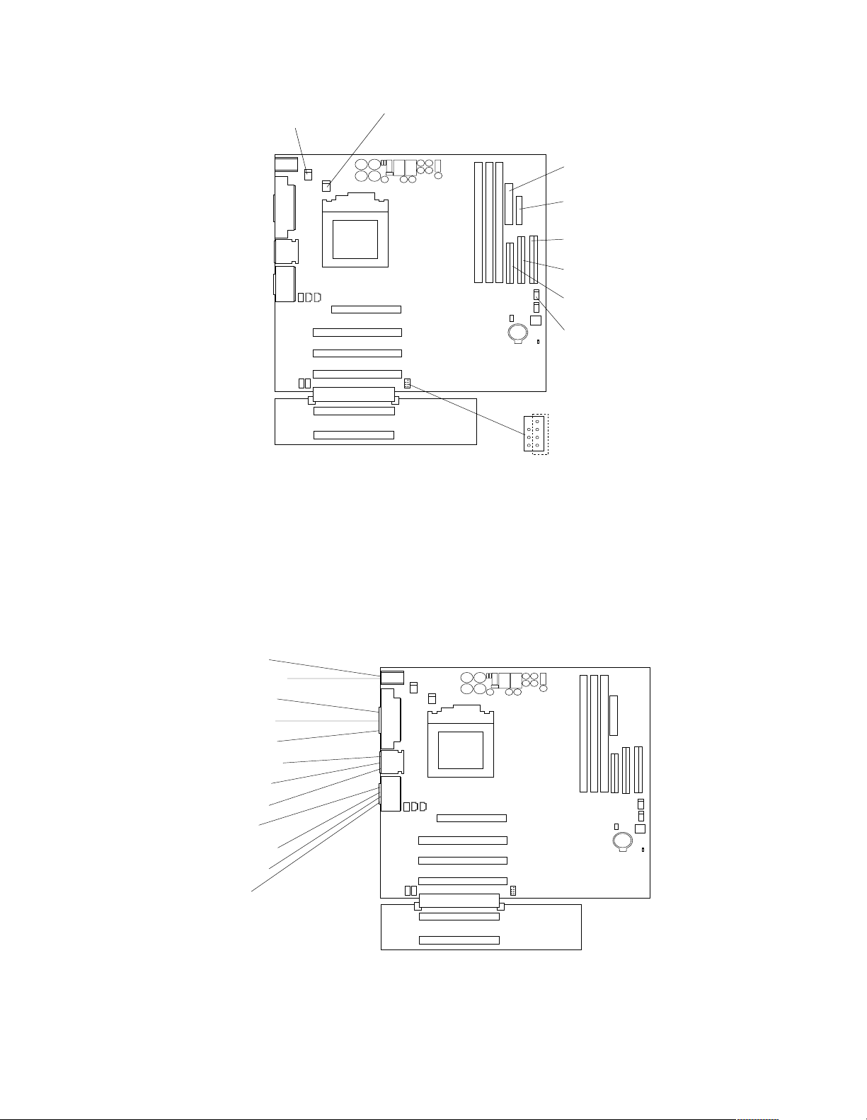
System fan 2
(SYSFA2)
Microprocessor
fan sink
(CPUFA1)
Main power
(JWR1)
Front panel
connector
(J1)
Secondary IDE
(IDE2)
Primary IDE
(IDE1)
Diskette drive
(FDD1)
Support bracket
assembly fan
(SYSFA3)
SCSI LED
(J3)
System board external connectors
The following illustration identifies system board connectors for external devices.
Mouse
Keyboard
Serial A
Para llel
Serial B
Ethernet
USB 2
USB 3
MIDI
Line out
Line in
Mic
Installing options 37
Page 46
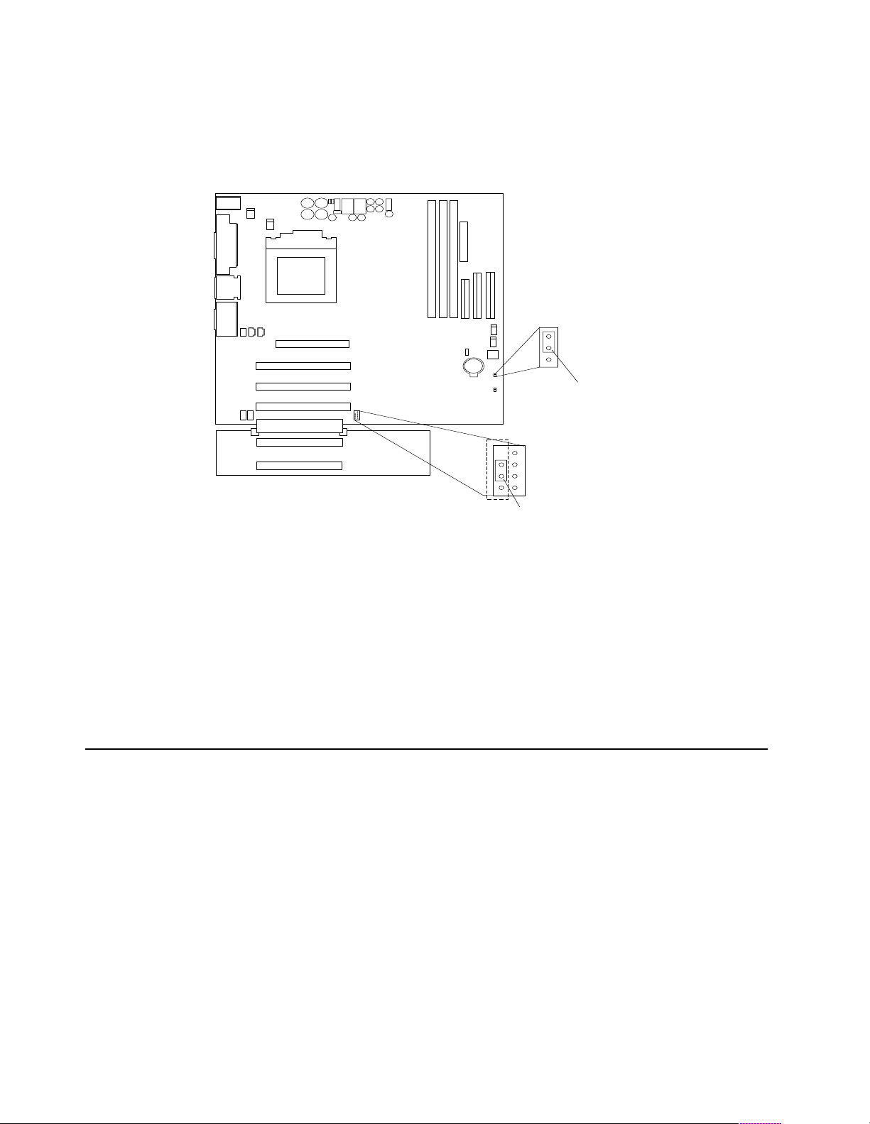
System board switches and jumpers
The followin g illust rat io n ident if ies the swit ch e s and jum pe r s on the sys tem board.
1
2
3
CMOS jumper
(JBAT1)
3
2
1
Boot block ju mper
For normal operations of the system, a jumper is installed on pins 2 and 3 of the boot
block jumper. See “Recover ing BIOS” on p age 14 for information about the boot block
jumper.
CMOS jumper
For normal operation of the system, a jumper is installed on pins 1 and 2 of the
complimentary metal oxide semiconductor (CMOS) jumper. See “Clearing CM OS” on
page 15 for information about the CMOS jumper.
Before you begin
Before you begin to inst all options in the server, read th e f ollowing information:
• Become familiar with the safety and handling guidelines provided in:
• When you need to ac ces s the insi de of t he ser ver to i nst all opti ons, you migh t fin d
Boot block jumper
(JROM1)
—“Safety information” on page 105;
—“Handling electrostatic discharge-sensitive devices” on page 108; and
—“Safety notices (multi-l ingual translations)” on page 109.
These guidelines will help you work safely while working with the server or
options.
it easier to lay the server on its side. If you do so, rotate the two front feet in
towards the server, so they do not break off due to the weight of the server.
38 Hardware Maintenance Manual: xSeries 200
Page 47

• Before you place the server in an upright position, rotate the two front feet a
quarter turn away from the server. For complete details, see “Moving the
stabilizing feet” on page 40.
• Make sure that you have an adequate number of properly grounded electrical
outlets for the server, monitor, and any othe r options that you intend to install.
• Back up all important data before you make changes to disk drives.
• For a list of supported options for the 200, refer to
http://www.ibm.com/pc/us/c ompat on the World Wide Web.
Working inside the server with the power on
The server is designed with safety in mind. Follow these guidelines when you work
inside a server that is turne d on :
• Avoid loose-fittin g clothing on your forearms. Button long-sleeved shirts before
working inside the server; do not wear cuff links while you are working inside the
server.
• Do not allow your necktie to hang inside the server.
• Remove jewe lry, such as bracelets, necklaces, rings, and loos e - fitting wrist
watches.
• Remove items from your shirt pocket (such as pens or pencils) that could fall into
the server as you lean over it.
• Avoid dropping any meta l lic ob jec ts, su ch as pape r cl ips, h air pins , or scr ews, in to
the server.
System reliability considerations
To help ensure proper coo ling and syst e m reliability, make sure that:
• Each of the drive bays either has a drive, or a filler panel and electromagnetic
compatibility (EMC) shield installed.
• There is space around the server to allow the server cooling system to work
properly. Leave about 127 mm (5 in.) of space around the fron t and rear of the
server.
• Cables for optional adapters are routed according to the instructions that are
provided with the adapters.
• A failed fan is replaced within 1 hour.
Handling static-sensitive devices
Attention: Static electricity can damage electronic devices and your system. To avoid
damage, keep static-sensitive devices in their static-protective bag un til you are ready
to install them.
To reduce the po ssib ility of ele ctrostat ic disch a rge, observ e the following precautions:
• Limit your movement. Movement can ca use static el e ctricity to build up around
you.
• Handle the device carefully, holding it by its edges or its frame.
• Do not touch so lder joints, pins, or exposed pr inted circuitry.
• Do not leave the device where others can handle and possibly damage the device.
Installing options 39
Page 48

• While the device is still in its anti-static package, touch it to an unpainted metal
part of th e sy stem unit for at least two seconds. (This drains static electricity from
the package and from your body.)
• Remove the device from its package and install it directly into your system unit
without setting it down. If it is necessary to set the device down, place it on its
static-pro tective package. (If your device is an adapter, place it component side
up.) Do not place the device on your system unit cover or on a metal table.
• Take additional care when handling devices during cold weather as heating
reduces indoor humidity and increases static electricity.
Moving the stabilizing feet
The two front feet attached to the bottom of the server rotate 90 degrees to provide
additional sta bilit y.
When you need to access the inside of the server to ins tall options, you might find it
easier to lay the server on its side. If you do so, rotate the feet in towards the server, so
they do not break off due to the weight of the server.
When you are finished installin g option s and ha ve ins talled the side cov er, turn the
two fro nt st abili zin g feet a quar ter turn out from t he s erv er and set it car ef ully bac k on
its feet.
Removing the side cover
Review the information in “Before you begin” on page 38.
The following illustrat io n show s ho w to remove the sid e co ver from the ser ver.
Note: The illustrations in this document might differ slightly from your hardware.
40 Hardware Maintenance Manual: xSeries 200
Page 49

Cover-release
latch
Complete the following steps to remove the side cover of the server:
1. Review the information in “Before you begin” on page 38.
2. Turn off the server and periphera l devic e s and disconnect all external cables and
power cords.
3. If necessary, unlock the server cover.
4. Pull out on the cover-release latch, which will slide the cover toward the rear of
the server about 12.7 mm (1/2 in.). Then, remove the cover from the server.
5. Pull out on the cover-release tab at the rear of the server; then, slide the cover
towar d th e f ront of the ser ve r and remove it.
Attention: For proper cooling and airflow, replace the cover before turning on the
server. Operating the server for extended periods of time (over 30 minutes) with the
cover removed might damage server compone nts.
Removing the bez e l
Key lock
The following illustrat io n show s ho w to remove the b ez el from the server.
Note: The illustrations in this document might differ slightly from your hardware.
Installing options 41
Page 50

Complete the following steps to remove the bezel:
1. Review the information in “Before you begin” on page 38.
2. Turn off the server and periphera l devic e s and disconnect all external cables and
power cords.
3. Remove the side cover (see “Removing the side cover” on page 40).
4. Press the bezel-release latch at the top of the server to disconnect the top of the
beze l from the server.
5. Release the two tabs at the top edge of the bezel and pull the top of the bezel
slightly away from the server.
6. Pull the bezel up to release the two tabs at the bottom edge of the bezel. Store the
bezel in a safe place.
Removing the sup p ort bracket asse mbly
When worki ng with some options such as hard disk drives, mi croprocessors, and
memory modu les you must first remove the support bracket assembly to access the
location of the option.
42 Hardware Maintenance Manual: xSeries 200
Page 51

Complete the following steps to remove the support bracket assembly:
1. Review the information in “Before you begin” on page 38.
2. Turn off the server and periphera l devic e s and disconnect all external cables and
power cords.
3. Disconnect the support bracket assembly fan cabl e from the connector (SYSFA3)
on the syst e m bo ard. For the location of the fan connector, see “System board
interna l ca b le co n ne c to rs ” on page 36.
4. Pull out, about 152.4 mm (6 in.), on the end of the support bracket assembly
located at the rear of the server.
5. Pull the front end of the support bracket assembly away from the server and place
the assembly aside.
To reinstall the support bracket assembly, reverse the previous steps.
Working with ad ap ters
Your server comes with adapter connectors, called slots. The AGP video adapter is
installed in the AGP slot. You can install up to five PCI adapters in PCI slots 1 through
5. All PCI expansion slots are 32-bit, 33 MHz slots.
Note: The illustrations in this document might differ slightly from your hardware.
The following illustration shows the location of the system expansion slots on the
system and PCI extender boards.
Installing options 43
Page 52

AGP slot
PCI slot 1
PCI slot 2
PCI slot 3
PCI slot 4
PCI slot 5
Adapter considerations
Before you install an adapter, review the following:
• Locate the documentation that comes with the adapter and follow those
instructions in addition to the instructions given in thi s chapter. If you need to
change the switch or jumper settings on your adapter, follow the instructio ns that
come with th e adapter.
• You can install full-length adapters in all five PCI expansion slots.
• The server supports 5.0V and universal PCI adapters; it does not support 3.3V
adapters.
• Your server uses a rotational interrupt technique to configure PCI adapters.
Because of this techni que, you can install a variety of PCI adapters that currently
do not support sharing of PCI interrupts.
• PCI expansion slots 1 through 5 are on PCI bus 0. The system scans the AGP slot
and PCI expansi on slots 1 throu gh 5 to assign system r e sources; th e n, the system
starts (boots) the PCI devices in the following order, if you have not changed the
default boot seq uence: P CI ex pansi on slots 1 and 2, sy ste m board int egrat ed drive
electronics (IDE) or SCSI devices, and then PCI expansion slots 3 through 5.
Note: To change the boot sequence for PCI devices, start the
Configuration/Setup Utility program, select Start Options from the main
menu, select Startup Sequence; then, select Second device (SCSI) to
designate the adapter boot sequence. See “Chapter . Configuring the
server,” on page 29 for details on using the Configuration/Setup Utility
program.
• For a lis t of su p p o rted options fo r yo u r s e rve r, refer to
http://www.ibm.com/pc/us/compat on the World Wide Web.
44 Hardware Maintenance Manual: xSeries 200
Page 53

Installing an adapter
Expansion
slot cover
Adapter
retaining
bracket
Adapter
Adapter
support
bracket
Complete the following steps to install an adapter:
Attention: When yo u han dle ESD - se nsitiv e de vices, ta k e p rec a u tions to avoid
damage from static electricity. For details on handling these devices, see “Handling
static-sensitive devices” on page 39.
1. Review the information in “Before you begin” on page 38.
2. Turn off the server and periphera l devic e s and disconnect all external cables and
power cords; then, r emove the side cover. See “Removing th e si de co ver ” on page
40 for details.
3. Determine which PCI expansion slot you will use for the adapter .
Note: Check the instructions that come with the adapter for any requirement s,
restrictions, or cabling instructions. It might be easier for you to route any
cables before you install the adapter.
4. If you are installing a full-length adapter, rotate the front adapter support bracket
to the open (unlocked) position.
5. Rota te th e rear adapte r ret a i n in g bracke t to th e o p e n (un l o c k e d) p os i t ion; then
place it over the rear of the server.
6. Remove the PCI expansion-slot cover. From the rear of the server, press in on the
slot cover. Grasp it and pull it out of the slot. Store it in a safe place for future use.
Attention: PCI expansion-slot covers must be installed on all vacant slots. This
maintains the electromagnetic emissions characteristics of the server and ensures
proper cooling of server components.
7. Remove the adapter from the static-pr otective package. Avoid touching the
components and gold-edge connectors on the adapter.
Installing options 45
Page 54

8. Place the adapter, component-side up, on a flat, static-protective surface.
9. Set any jumpers or switches as described by the adapter manufacturer.
10. To install the adapter, carefully grasp the adapter by its top edge or upper corners ,
and align it with the expansion slot guides; then, press the adapter firmly into the
PCI expansion slot.
Attention: When you install an adapter in the server, be sure that it is completely
and correctly seated in the PCI expansion slot before you turn on the server.
Incomplete insertion might cause damage to the system board or the adapter.
1 1. Connect required cables to the adapter.
Attention: Route cables so that they do not block the flow of air from the fans.
12. If you have another adapter or other options to install, do so now.
13. If you have installed a full-length adapter, rotate the front adapter support bracket
to the closed (locked) position.
14. R e i nstall the rea r ada p ter retain i ng brack e t; th en , rota te the brac k e t to the cl o s e d
(locked) position.
15. Reinstall the side cover, see “Installing the cover” on page 59 for detai ls.
16. Reconnect the external cables and power cords; then, turn on the peripheral
devices and the se rver.
Installing a SCSI or ServeRAID adapter (some models)
Complete the following steps to install a SCSI or ServeRAID adapter:
1. If you have not already installed the SCSI adapter, complete steps 1 through 10 of
“Installing an adapter” on page 45. Then, return here to complete the installation.
SCSI
signal
cable
Adapter
retaining
bracket
SCSI signal
cable connector
SCSI activity
indicator cable
connector
SCSI
Adapter
SCSI
activity
indicator
cable
SCSI
LED
(J3)
Adapter
support
bracket
46 Hardware Maintenance Manual: xSeries 200
Page 55

2. Connect the SCSI signal cable to the adapter and one or more of the signal cable
connectors to the rear of the SCSI devices.
3. Connect the SCSI activity indicator cable to the adapter and to the SCSI LED
connector (J3) on the system board. See “System board internal cable connector s”
on page 36 for the location of this conne ctor.
Note: If you are installing a ServeRAID adapter and already have a SCSI adapter
installed, remove the SCSI adapter and store i t for future use.
4. If you have other adapters or options to install or remove , do so now.
5. Rotate the front adapter support bracket to the closed (locked) position.
6. Rein s ta l l th e rea r ada p ter retain i ng brack e t; the n , rota te the brac k et to the closed
(locked) position.
7. Reinstall the side cove r, see “Installing the cover” on page 59 for details.
8. Reconnect the external cables and power cords; then, turn on the peripheral
devices and the se rver.
Installing internal drives
Different types of driv es enabl e your server t o r ead multiple types of media and store
data in different formats. Depending on your server model, you might have one or
more of the following drives installed.
• Diskette
• Hard disk
• CD-ROM
• Tape
Internal drive bays
Your server comes with an IDE CD-ROM drive installed in bay 1, a 3.5-in., 1.44 MB
diskette drive in bay 3, and a hard disk drive in bay 5. For instructions on insta lling
drives in bays 1 and 3, see “CD-ROM dr ive ” on page 76 and “Floppy disk drive” on
page 77.
Note: The illustrations in this document might differ slightly from your hardware.
Installing options 47
Page 56

Bay 1
Bay 2
Bay 3
Bay 4
Bay 5
Bay 6
Bay 7
Notes:
1. Diskette drives, tape drives, and CD-ROM drives are removable-media dri ves.
You can install removable-media drives in bays 1, 2, 3, and 4.
2. You can in stal l a 3. 5-in., slim-hi gh, or a 5. 25- in., half -high , r emovable-med ia drive,
such as a tape backup drive, in bay 2.
3. You can only install a 3.5-in., slim-high , removable -m edia dri ve in bay 4.
4. Th e xSeries 200 server supports only one diskette drive, which uses 1 MB and 2
MB diskettes.
5. Before you install a 3.5-in. drive in a 5.25-in. bay, you must attach the 5.25 in.
conversi on kit, supplie d with your option , to the 3.5-in drive. Refer to the
docu mentati on th a t co mes with th e o p ti o n for the con ve r sion kit in st a l la ti o n
instructions.
Note: Only 3.5-in. options that ship with proper mounti ng hardware can be
supported in the 5.25-in. bays.
6. If you have a tape backup drive in your server, use a dry process cleaning
cartridge to clean the tape head two hours after you first use a new data cartridge.
Then, clean the tape head once a month, or after each eight hours of continuous
read/write operations, whichever occurs first. For complete details about the tape
backup dri ve, refer to the documen t a tion that comes with your se rver or your
backup option.
7. Th e electromagnetic interference (EMI) integrity and cooling of the server are
both protected by having bays 1 through 4 covered or occupied. When you install
a drive, save the EMC sh ield an d fil ler pan e l from the bay, in case you later
remove the drive and do not replace it with another.
8. For a li s t of su p p o rted options fo r yo u r s e rve r, refer to
http://www.ibm.com/pc/us/compat on the World Wide Web.
48 Hardware Maintenance Manual: xSeries 200
Page 57

Preinstallation steps (all bays)
Before you install drives in the server, verify that you have all the cables and other
equipment specified in the documentation that comes with the drive. You might also
need to perform certain preinstallation act ivities. Some of the steps are required only
during the initial installation of an option.
1. Read “Safety information” on page 105 and the documentati on th at comes with
your drive.
2. Choose the bay in which you want to ins tall the drive.
3. Ch eck the instructions that come with the drive to see if you need to set any
switches or jumpers on the drive. If you are installing a SCSI device, be sure to set
the SCSI ID for that device.
Installing a drive in bay 2 or 4
Note: The EMI integrity and cooling of the server are both protected by having the
bays covered or occupied. When you install a drive, save the filler panel and
EMC shield from the bay, in case you later remove the drive and do not replace
it with another.
EMC shield
Filler panel
Complete the following steps to install a drive in bay 2 or 4:
1. Read the information in “Preinstallation steps (all bays)”.
2. Turn off the server and periphera l devices and disconnect external cables and
power cords; then, remove the side cover (see “Removing the side cover” on page
40 for details).
3. Remove the support bracket assembly and disconnect the fan cable from the
connector (SYSFA3) on the system board. See “Removing the support bracket
Installing options 49
Page 58

assembly” on page 42 and “System board internal cable connectors” on page 36
for the location of the fan cable connector.
4. Use a screwdriver to gently pry the filler panel and EMC shield away from the
server.
Note: If you are installing a drive that is a laser product, observe the following
safety precaution:
CAUTION:
When laser products (such as CD-ROMs, DVD drives, fiber optic devices, or
transmitters) are installed, note the following:
• Do not remove the covers. Removing the covers of the laser product could
result in exposure to hazardous laser radiation. There are no serviceable
parts inside the device.
• Use of controls or adjustments or performance of procedures other than
those specified herein might result in hazardous radiation exposure.
DANGER: Some laser products contain an embedded Clas s 3A or Class 3B laser
diode. Note the following. Laser radiation when open. Do not stare
into the beam, do not view directly with optical instruments, and
avoid direc t expo sure to the beam.
5. Touch the static-protective bag containing the drive to any unpainted metal
surface on the server; then, remove the drive from the bag and place it on a staticprotective surface.
6. Set any jumpers or switches on the drive according to the documentation that
comes with th e dr i v e .
7. Install the drive.
• If you are installing a 5.25-in drive in bay 2, push the drive into the bay; then,
use the two screws to attach the drive to the drive cage.
• If you are installing a 3.5-in drive in bay 2, you must attach the 5.25-in
conversi on kit, supplie d with your option, to the 3.5-in dri ve.
Note: You can only install a 3.5-in device in bay 4.
8. Cable the drive.
• If the drive is an IDE device, plug one connector of the IDE signal cable into
the back of the drive and the other end of the cable into the IDE connector
(IDE1) on the system board. For the location of the IDE connectors, see
“System board internal ca ble connectors” on page 36.
• If the drive is a SCSI device, plug one connector of the SCSI signal cable into
the back of the drive and the other end of the cable into the SCSI adapter. See
“Installing an adapter” on page 45.
50 Hardware Maintenance Manual: xSeries 200
Page 59

Note: Make sure to route the signal cable so that it does not block the air
flow to the re ar of the drive s or over the microprocessor.
9. If you have other option s to install or remove, do so now.
10. Connect one of the power cables from the power supply in to the back of the d rive.
The connectors are keyed and can be inserted only one way.
1 1. Replace the support bracket assembly and reconnect the fan cable to the
connector (SYSFA3) on the system board. See “System board internal cable
connectors” on page 36 for the location of the fan cable connector.
12. Reinstall the side cover, see “Installing the cover” on page 59 for details.
13. Reconnect the external cables and power cords; then, turn on the peripheral
devices and the se rver.
Installing a hard disk drive in bay 5, 6, or 7
Drive cage retention tab
Drive cage release tab
Complete the following steps to install a hard disk drive in bay 5, 6, or 7.
Attention: When you handle ESD-sensitive devices, take precautions to avoid
damage from static electricity, see “Handling static-sensitive devices” on page 39.
1. Read the information in “Preinstallation steps (all bays)” on page 49.
2. Turn off the server and periphera l devic e s and disconnect all external cables and
power cords; then, remove the cover (see “Removing the side cover” on page 40
for details).
3. Remove the support bracket assembly. See “Remov in g the su p port br a cket
assembly” on page 42.
4. Remove the support bracket assembly and disconnect the fan cable from the
connector (SYSFA3) on the system board. See “Removing the support bracket
Installing options 51
Page 60

assembly” on page 42 and “System board internal cable connectors” on page 36
for the location of the fan cable connector.
5. Access the drive cage.
a. If your server has hard disk drives installed in the drive cage, disconnect the
power and signal cables from the rear of the drives.
b. Rotate the drive cage out of the server until it locks into place over the drive
cage retention tab.
Note: Before you install a hard disk drive, ensure that the drive cage locks
into place over the drive cage retention tab by pressing on the side of
the drive cage.
6. Attach the blue, plastic guide rails to the sides of the drive using the screws
provided.
7. Slide the drive into the drive cage until the plastic tabs on the guide rails lock into
place in the drive cage.
8. Lift the drive cage up and press in on the drive cage release tab; then, rotate the
drive cage back into the server.
Note: Clear any cables that might impede the replacement of the drive cage.
9. Connect the power and signal cables to the rear of each drive.
Note: Make sure to route the si g nal cable so that it d oe s not block the air flow to
the rear of the drives or over the microprocessor.
10. If you have other options to install or re move, do so now.
1 1. Replace the support bracket assembly and reconnect the fan cable to the
connector (SYSFA3) on the system board. See “Removing the support bracket
assembly” on page 42 and “System board internal cable connectors” on page 36
for the location of the fan cable connector.
12. Reinstall the side cover, see “Installing the cover” on page 59 for detai ls.
13. Reconnect the external cables and power cords; then, turn on the peripheral
devices and the se rver.
Installing memory modules
Adding memory to your server is an easy way to make programs run faster. Yo u can
incr ease the amount of memory in your server by instal li ng options called memory
modules. Each module contains one industry-standard, dual in-line memory module
(DIMM). Your server uses a noninterleaved memory configuration.
Memory consider ations :
• The serve r comes wi th a DIMM in st alle d on the sy st em boar d i n DIMM c onne ctor
1.
• When installing add itiona l mem ory mod ules , install the sec ond mem o ry modu le
in DIMM connector 2, and the third in DIMM connector 3. (See the illustration in
this se ction for memory connector location s.)
• The xSeries 200 server supports 64 MB, 128 MB, 256 MB, and 512 MB DIMMs.
Your ser ve r supports a minimum of 64 MB and a maximum of 1.5 GB of sy stem
memory. See the ServerProven list at http://www.ibm.com/pc/compat for a list
of memory modules for use with your server.
• Installing or removing DIMMs chang es the configur ation inf orm ati on in the
server . T herefore, after installing or removi ng a DI MM, you m ust chan ge and save
the new configuration information by using the Configuration/Setup Utility
program. When you restart the server, the system displays a message indicating
that the memory configurati on has changed. Start the Con figurat ion/S etu p
52 Hardware Maintenance Manual: xSeries 200
Page 61

Utility program and select Save Settings. See “Ch apter . C onf igur ing the server,”
on page 29 for more information.
• The illustrations in this document might differ slightly from your hardware.
DIMM connector 1
DIMM connector 2
DIMM connector 3
Retaining clip
Complete the following steps to install a DIMM:
Attention: When you handle ESD-se nsitive devic e s, take precautions to avoid
damage from static electricity. For details on handling these devices, see “Ha ndling
static-sensitive devices” on page 39.
1. Review the safety precautions in “Safety information” on page 105.
2. Turn off the server and peripheral devices, and disconnect all external cables and
power cords; then, remove the cover (see “Removing the side cover” on page 40
for details).
3. Remove the support bracket assembly and disconnect the fan cable from the
connector (SYSFA3) on the system board. See “Removing the support bracket
assembly” on page 42 and “System board internal cable connectors” on page 36
for the location of the fan cable connector.
4. Touch the static-protective package containi n g the DIMM to any unpainted metal
surface on the server. Then, remove the DIMM from the package.
5. Install the DIMM:
a. If you are installing a DIMM in connector 1, remove the AGP adapter.
Remove the AGP adapter only if you are replacing the DIMM in connector 1.
See “System and PCI ext e nder board options connectors” on page 35 for the
location of the AGP slot. See “Installing an adapter” on page 45 for details
about removing the AGP adapter.
b. Open the retai ni ng clip on each end of the DIMM slot . Turn the DIMM so that
the pins align correctly with the connector.
Installing options 53
Page 62

Attention: To avoid breaking the retaining clips or damaging the DIMM
connectors, open and close the clips gently.
c. Insert the DIMM into the connector by aligning the DIMM edges with the
slots at each end of the DIMM connector. Firmly press the DIMM straight
down into the connector by applying pressure on both ends of the DIMM
simultaneously. Be sure that the retaining clips snap into the locked position
when the DIMM is firmly seated in the connector.
d. If a gap exists between the DIMM and the retaining clips, the DIMM has not
been properly installed. In this case, open the retaining clips and remove the
DIMM ; the n, reinsert the DIMM.
e. If you removed the AGP adapter, r eins tall it now, see “In s talli ng an adap ter”
on page 45.
6. If you have other option s to install or remove, do so now.
7. Replace the support bracket assembly and reconnect the fan cable to the
connector (SYSFA3) on the system board. See “Removing the support bracket
assembly” on page 42 and “System board internal cable connectors” on page 36
for the location of the fan cable connector.
8. Replace the side cover, see “Installing the cover” on page 59.
9. R econnect the external cables and power cords, and turn on the peripheral
devices and the se rver.
If you want to remove a DIMM, reverse the previous steps.
Removing and insta lling a mic roprocesso r
The serve r on ly supports one microprocessor, which is installed on the system board
in the microprocessor connector (U5).
Notes:
1. Before you install a new microprocessor, review the documentation that comes
with th e mi cro p roc e ssor, so that you ca n de t e rmine wh e the r you nee d to update
the server BIOS. The latest level of the BIOS for your server is available through
the World Wide Web.
2. Fo r a list of supported operating systems, see
http://www.ibm.com/pc/us/c ompat / on the World Wide Web.
Note: The illustrations in this document might differ slightly from your hardware
Attention: To avoid damage and ensure correct server operation when you install a
new microprocessor, use a microprocessor that has the same cache size and type, and
the same clock speed. Microprocessor internal clock frequencies and external clock
frequencies must be identical. See the ServerProven list at
http://www.ibm.com/pc/compat for a list of microprocessors for use with your
server.
54 Hardware Maintenance Manual: xSeries 200
Page 63

Removing a microprocessor
Complete the following steps to remove a microprocessor.
Microprocessor
connector
Microprocessor
Heat sink
Heat sink
retainer
Microprocessor
orientation indicator
Lever
Attention: When you handle ESD-se nsitive devic e s, take precautions to avoid
damage from static electricity. For details on handling these devices, see “Ha ndling
static-sensitive devices” on page 39.
1. Review the safety precautions listed in “Safety information” on page 105.
2. Turn off the server and periphera l devic e s and disconnect all external cables and
power cords; then, remove the cover (see “Removing the side cover” on page 40
for details).
3. Remove the support bracket assembly and disconnect the fan cable from the
connector (SYSFA3) on the system board. See “Removing the support bracket
assembly” on page 42 and “System board internal cable connectors” on page 36
for the location of the fan cable connector.
4. Push down and back on the heat-sink retainer to remove it from the heat sink.
5. Firmly grasp the heat sink and lift it off the microprocessor.
Note: Once you remove the heat sink from the microprocessor, you must replace
it with a new device.
Pull out and lift up the release lever and remove the microprocessor from the
connector. Store the mic roprocessor in a static-p rotective bag for possibl e future
use.
6. If you are installing a new microprocessor, continue with step 4 in “Installing a
microprocessor” on page 56.
Installing options 55
Page 64

Installing a microprocessor
Complete the following steps to install a microprocessor:
Attention: When you handle ESD-se nsitive devic e s, take precautions to avoid
damage from static electricity. For details on handling these devices, refer to IBM W eb
site http://www.ibm.com/ and use a search term of ESD.
1. Review the safety precautions listed in “Safety information” on page 105.
2. Turn off the server and periphera l devic e s and disconnect all external cables and
power cords; then, remove the cover (see “Removing the side cover” on page 40
for details).
3. Remove the support bracket assembly, see “Removing the support bracket
assembly” on page 42 for instructions.
4. Install the microprocessor:
a. Touch the s tatic -pro tecti ve package c ontain ing th e new micr opro cess or to a ny
unpainted metal surface on the se rver; then, remove the microprocessor from
the package.
b. Pull out and lift up on the microprocessor release lever to unlock the
microprocessor connector.
c. Orient th e microprocessor over the microprocessor connector as shown in the
following illustration. Carefully press the microprocessor into the connector.
Lever
Microprocessor
connector
Microprocessor
Microprocessor
orientation indicator
Note: Do not use excessive force when pressing the microprocessor into the
connector.
5. Push the microprocessor release lever down to lock the microp rocessor into the
connector.
6. Install a heat sink or fan sink.
• If you are installing a heat sink on the microprocessor:
Note: Refer to the illustration in “Removing a microprocessor” on page 55.
56 Hardware Maintenance Manual: xSeries 200
Page 65

a. Peel the plastic protective strip off the bottom of the heat sink. Make sure
the squa re of t hermal ma te ri al is stil l on t he bo tto m of t he heat si nk; i f n ot,
replace the it with a new heat sink.
b. Align and place the heat sink on top of the microprocessor.
c. Align and place the heat sink retainer over the heat sink, then snap it into
place.
• If you are installing a fan sink on the microprocessor:
Fan sink
connector
Lever
Microprocessor
connector
Microprocessor
Fan sink
Fan-sink
retainer
Microprocessor
orientation indicator
a. Peel the plastic protectiv e strip off the bott om of the fan sink. Make sure
the square of thermal material is still on the bottom of the fan sink; if not,
replace the it with a new fan sink.
b. Align and place the fan sink on top of th e microprocessor.
c. Align and pu s h the f an-sink retai ner throu gh th e g roo ve in the center of
the fan sink.
d. Insert a small, flat-bladed screwdriver into the tab on the fan-sink
retainer.
e. Press the screwdriver down to snap the fan-sink retainer into place.
f. Connect the fan-sink power cable to the microprocessor fan-sink
connector (CPUFA1) on the system board. See “System board internal
cable co nn ectors” on page 36 for the location of the microprocessor fan-
sink connector.
7. If you have other options to install or remove, do so now; ot herwise, rep lace the
support bracket assembly. See “Removing the support bracket assembly” on
page 42 for details. See “System board internal cable connectors” on page 36 for
Installing options 57
Page 66

the location of the fan cable connector. See “Installing the cover” on page 59 for
instructions on installing the cover.
8. Reconnect the external cables and power cords; then, turn on the peripheral
devices and the se rver.
Installing a security U-bolt
To help prevent hardware theft, you can add a security U-bolt and cable to your
server. After you add the security cable, make sure that it does not interfere with
other cables that are connected to the server.
Complete the following steps to install a U-bolt:
1. Review the safety precautions listed in “Safety information” on page 105.
2. Turn off the server and periphera l devic e s and disconnect all external cables and
power cords; then, remove the cover (see “Removing the side cover” on page 40
for details).
3. Use a screwdriver to remove the two metal knoc k o u t s.
4. Insert the U-bolt through the rear pan e l; then, attach and tighten the nuts.
5. If you have other option s to install or remove, do so now.
6. Replace the side cover, see “Installing the cover” on page 59.
7. Thread the cable through the U-bolt and aroun d an object that is a part of or
permanently secured to the building structure or foundation, and from which it
cannot be removed; then, fasten the cable ends together with a lock.
58 Hardware Maintenance Manual: xSeries 200
Page 67

8. R econnect the external cables and power cords, and turn on the peripheral
devices and the se rver.
Completin g th e ins tal lat i on
Attention: For correct cooling and airflow, install the cover before turning on the
server. Operating the server for extended periods of time (over 30
minutes) with the top cover removed might damage server components.
To complete the installation, you must reinstall the cover, reconnect all the cables that
you disconnected earlier and, for certain options, run the Configuration/Setup Utility
program. Follow the instructions in this section.
Note: If you have just plugged the power cords of the server into an el ect rical outlet,
you will have to wait approximately 20 seconds before pressing the powercontrol button.
Installing the cover
The following illustration shows how install the server side cover .
Note: The illustrations in this document might differ slightly from your hardware.
Note: If you removed the support bra cket assembly after yo u removed th e cover,
reinstall it before you install the cover . See “Removing the support bracket
assembly” on page 42 for details.
Complete the following steps to install the server cover:
1. Clear any cables that might impede the replacement of the cover.
2. Install the side cove r by placing it int o p osition on the server. Close the cover
release latch to secure the cover in place.
Installing options 59
Page 68

3. Lock the cover.
4. If you have not done so already, make sure that the two front stabilizing feet are
rotated outward so that they properly support the server. Rotate each individual
foot outward 90 degrees.
5. R econnect the external cables and power cords to the server, and then plug the
power cords into electrical outlets.
6. Turn on all peripheral devices; then, turn on the server.
Updating the server configuration
When you start th e ser ver for t he fi rst ti me after you add or r emov e an inte rnal optio n
or an external SCSI device, you might see a message telling you that the configuration
has changed. The Configuration/Setup Utility program automatically starts so that
you can save the new configuration information. See “Chapter . Configuring the
server,” on page 29.
Some opti ons h av e dev ice dr iver s t hat y ou n eed to i nsta ll. Refer to t he do cume nta ti on
that comes with your option for information about installing any required device
drivers.
If the server has a ServeRAID adapte r ins tal led and you have installed or removed a
hard disk dri ve, re fer to the do cumen tati on th at co mes with your S erve RAID ada pter
for information about reconfiguring your disk arrays.
Connecting external options
You can attach a SCSI storage expansion enclosure to the server.
Installation pr oced ure
To attach an external device:
1. Read “Before you begin” on page 38 and the doc umentat ion th at comes with you r
options.
2. Be sure the server and all attached devices are tu rned off.
3. Follow the instructions that come with the option to prepare it for installation and
to conn ect it to the se rver.
Note: If you are attaching a SCSI device, see “Ultra 3/160 SCSI connector (some
models)” on page 70 for SCSI ID and cabling information.
I/O connector locations
The following illu strat io n show s the input /o ut put conne c tor s (ports ) and the
expansion slots on the rear of the server. For pin assignments and othe r details abou t
these connectors, see “Input/output ports” on page 61.
60 Hardware Maintenance Manual: xSeries 200
Page 69

Power cord
connector
Mouse
Keyboard
Parallel
Serial A
Serial B
Ethernet
USB 2
USB 3
Line out
Line in
Mic
MIDI
Video
Note: If the server is a SCSI model, the SCSI adapter will be located in PCI slot 1; the
external connector will appear in the slot below the video connector. See
“System and PCI exte nd e r board options connector s” on page 35 for the
location of the PCI slots.
Input/output ports
This section provides information about the I/O ports on your server. These ports
include the following:
• One mouse port
• One keyboard port
• One parallel port
• Two serial ports
• One Ethernet port
• Two USB ports
• Line out
• Line in
• Mic
• MIDI
• One video port
• One Ultra 3/160 SCSI port (some models)
Installing options 61
Page 70

Mouse port
The system board has one mouse port that supports a mouse or other pointing device.
The mouse connector is located on the rear of your server, see “I/O connector
locations” on page 60 for its location.
6
4
2
5
3
1
Table 7. Mouse connector pin-number assignm ent s .
Pin Signal
1Data
2 Not connected
3Ground
4+5 V dc
5Clock
6 Not connected
Keyboard port
There is one keyboard port on the rear of your server, see “I/ O connector locations”
on page 60 for its location.
Note: If you attac h a standard (non-USB) keyboard to the keyboard conne ctor , the
USB ports and devices will be disabled during the power-on self-test.
6
4
2
5
3
1
Table 8. Keyboard connector pin-number assignments .
Pin I/O Signal
1I/O Data
2N/AReserved
3N/AGround
4 N/A +5 V dc
5 I/O Keyboard clock
6N/AReserved
62 Hardware Maintenance Manual: xSeries 200
Page 71

Parallel connector
Your server has one parallel connector. This connector supports three standard
Institute of Electrical and Electronics Engineers (IEEE) 1284 modes of operation:
standard parallel port (SPP), enhanced parallel port (EPP), and extended capability
port (ECP).
Viewing or changing the connector assignments: You can use the built-in
Configuration/ Se tup Ut ility program to config ure the parallel connec tor as
bidirect ional; that is, so that data can be both read from and writte n to a device. In
bidirectional mode, the server supports the ECP and EPP modes.
Complete the following steps to view or change the parallel-connector assignment:
1. Restart the server and watch the monitor screen.
2. When the message Press F1 for Configuration/Setup appears, press F1.
3. When the Configuration/Setup Utility menu appears, select Devices & I/O Ports;
then, press Enter.
4. Select the parallel connector; then, use the arrow keys to advance through the
settings av ailable.
Note: When you configure the parallel connector as bidirectional, use an IEEE
1284-compliant cable. The cable must not exceed 3 meters (9.8 feet) .
5. Press Esc twice to return to the Configuration/Setup main menu; then, select
Save & Exit Setup to exit from the Configuration/Setup Utility main menu.
Parallel co nne c t or : There is a 25-pin, female D-shell parallel connector on the rear of
your server, see “I/O connector loca t i on s” on page 60 for the location of this
connector. The following table shows the pin-number assignments for the parallel
connector.
13
25
1
14
Installing options 63
Page 72

Table 9. Parallel connector pin-number assignments.
Pin I/O SPP/ECP Signal EPP Signal
1O -STROBE -WRITE
2 I/O Data 0 Data 0
3 I/O Data 1 Data 1
4 I/O Data 2 Data 2
5 I/O Data 3 Data 3
6 I/O Data 4 Data 4
7 I/O Data 5 Data 5
8 I/O Data 6 Data 6
9 I/O Data 7 Data 7
10 I -ACK -ACK
11 I BUSY -WAIT
12 I PE (paper end) PE (paper end)
13 I SLCT (select) SLCT (select)
14 O -AUTO FD (feed) -AUTO FD
15 I -ERROR -ERROR
16 O -INIT -INIT
17 O -SLCT IN -SLCT IN
18 - Ground Ground
19 - Ground Ground
20 - Ground Ground
21 - Ground Ground
22 - Ground Ground
23 - Ground Ground
24 - Ground Ground
25 - Ground Ground
Serial connectors
Your server has two standard serial connectors: Serial connector A and Serial
connector B.
Some application programs requir e spec i fic connectors, and some modems function
prope rly only at cert ain communica tion connector addresse s. You might need to u se
the Configuration/Setup Utility program to change communication connector
address assignments to prevent or resolve address conflicts.
Viewing or changing the serial-connector assignments: Complete the following
steps to view or change the serial-connector assignments:
1. Restart the server and watch the monitor screen.
2. When the message Press F1 for Configuration/Setup appears, press F1.
64 Hardware Maintenance Manual: xSeries 200
Page 73

3. When the Configuration/Setup Utility menu appears, select Devices & I/O Ports;
then, press Enter.
4. Select the serial connector; then, use the arrow keys to advance through the
available settings.
5. Press Esc twice to return to the Configuration/Setup Utility main menu; then,
select Save & Ex it Se tu p to exit from the Configuration/Setup Utility main menu.
Serial connectors: There are two 9-pin, male D-shell serial connectors on the rear of
your server, see “I/O connector loca t i on s” on page 60 for the location of these
connectors. The table b e low shows the pin-assignment s f o r the serial connectors.
1
69
5
Table 10. Serial connectors pin-number ass ignment s.
Pin Signal Pin Signal
1 Data carrier det e ct 6 Data set ready
2 Receive data 7 Request to send
3 Transmit data 8 Clear to se nd
4 Data terminal r eady 9 Ring indicator
5 Signal ground
Ethernet connector
Your server comes with an integrated Ethernet controller. This controller provides an
interface for connecting to 10-Mbps or 100-Mbps networks and provides full-duplex
capability, which enables simultaneous transmission and reception of data on the
Ethernet LAN .
To access the Ethernet connector, connect a Category 3, 4, or 5 unshi elded twis ted -pair
(UTP) cable to the RJ-45 connector on the rear of your server. See “I/O connector
locations” on page 60.
Note: The 100BASE-TX Fast Ethe rnet standard requires that the cabling in the
network be Category 5.
Configuring the Ethernet controller: When you connect your server to the network,
the Ethern e t controller automatically detec ts the data-transfer rate (1 0Mbps or
100 Mbps) on the network and then sets the controller to operate at the appropriate
rate. In addition, if the Ethernet connector that your server is connected to supports
auto-negotiation, the Ethernet c ontroller will set the appropriate duplex state. That is,
the Ethernet controller will adjust to the network data rate, whether the data rate is
standard Ethernet (10BASE-T), Fast Ethernet (10 0BASE-TX) , half duplex (HDX), or
FDX. The controller supports HDX and FDX modes at both speeds.
The Ethernet controller is integrated on the system board. You do not need to set any
jumpers or configure the controller for your operating system before you use the
Ethernet controller. However, you must install a device driver to enable your
operating system to address the Ethernet controller. The device drivers are provided
on the ServerGuide CDs.
Installing options 65
Page 74

Failover for redundant Ethernet: The IBM 10/100 Ethernet adapter or the IBM
10/100 Etherjet™ PCI family of adapters are optional, r e dundant network interface
card (NIC) adapters that you can install in your server. If you install this NIC adapter
and connect it to the s ame logical segment as the primary Ethernet controller, you can
configure the server to support a failover function. You can configure either the
integrated Ethernet controller or the NIC adapter as the primary Ethernet controller.
In failover mode, if the primary Ethernet controller detects a link failure, all Ethernet
traffic that is associated with it is switched to the redundant (secondary) controller.
This switching occurs without any user intervention. When the primary link is
restored , the Ethernet traffic switches back to the primary Ethernet controller.
High Performance Ethernet Modes: Your Ethernet controller supports optional
modes, such as teaming, priority packets, and virtual LANs, which provide higher
performance and throughput for your server.
Teaming Mode: Your Ethernet controller provides options, called teaming opt io n s.
These options increase throughput and fault tolerance when running with Windows
NT 4.0 or NetWare 4.1x or later.
• Adapter Fault Tolerance (AFT) provides automatic redundancy for your adapter.
If the primary adapter fails, the secondary adapter takes ov er. Adapter fault
tolerance supports from 2 to 4 adapters per team.
• Adaptive Load Balancing (ALB) enables you to balance the transmission data
flow among 2 to 4 adapters. ALB also includes the AFT option. You can use ALB
with any 100BASE-TX switch.
• Cisco Fast EtherChannel (FEC) creates a team of 2 to 4 adapters to increase
transmission and reception throughp u t. FEC also includ e s the AFT option. You
can only use FEC with a switch that has FEC capability.
Teaming requires yo u to instal l a t leas t o ne addi tio nal Et hernet adapte r. For additional
information about th e teami n g modes, refer to the documentat i on th at comes with
these additional adapters.
Priority Packet Mode: Priority Packet is a traffic-prioritization utility that enables you
to set up filters to process high-priority traffic before normal traffic. You can send
information from critical nodes or applications with an indicated priority. Because
you set this priority at the host or en try poin t o f the network, the network devices can
base forwarding decisions on priority information defined in the packet.
Priority Packet information is available on the IBM Network ing Web site at
http://www.ibm.com/networking/support
Priority Packet prioritizes traffic based on priority filters. These are parameters you
assign to outgoing (transmit) pac kets. Using the Priorit y Filter Wizard, you can set u p
predef ined or custom p ri o rity filte rs based on a node medium access cont rol (MAC)
address, Ethernet type, or by various properties of the protocol and connector.
Priority Packet provides two different methods for prioritizing traffic: IEEE 802.1p
tagging and High Priority Queue.
IEEE 802.1p is a new IEEE standard for tagging, or adding additi onal bytes of
information to packets with different priority l evels. Packet s ar e tagged with 4
additional bytes, which increase the packet size and indicate a priority level. When
you send these packets out on the network, the higher priority packets are transferred
first. Priority packet tagging (also know n as Traffic Class Expediting) enables the
adapter to work with other elements of the network (such as switches and routers) to
deliver priority packe ts firs t. You can assign specific priority levels from 0 (low) to 7
(high).
Y o u can ass ign val ues to packets based on thei r prior ity when y ou use the IE EE 802.1p
standard for packet tagging. Th is method requires a network infra structure that
66 Hardware Maintenance Manual: xSeries 200
Page 75

supports packet tagging. The routing devices receiving and transferring these packets
on your network must support 802.1p for tagging to be effective.
After you set up the priority fi lter in Priority Packet, you must start IBMSet and select
802.1p/802.1Q Tagging on the Advanced tab.
Note: IEEE 802.1p tagging increases the size of the packets it tags. Some hubs and
switches will not recognize the larger packets and will drop them. Check your
hub or switch documentation to see if they support 802.1p. (You can configure
the switch to strip the tags from the packets and send it on to the next
destination as normal traffic.) If these devices do not support 802.1p, or if you
are not sure, use high priority queue (HPQ) to prioritize network traffic.
The requirements for effectively using IEEE 802.1p tagging are:
• The other devices receiving and routing 802.1p tagged packets must support
802.1p.
• The adapters on these devices must support 802.1p. The Ethernet controller in
your xSeries 200 and all IBM 10/100 Ethernet Security Adapters support 802.1p.
• The adapter cannot be assigned to an adapter team.
• If you are setting up virtual local area networks (VLANs) and packet tagging on
the same adapter, 802.1p/802.1Q tagging must be enabled on the IBMSet
Advanced tab.
If your n etwo rk in fras tru ctur e d evi ces do not su ppo rt IEEE 802 .1p o r you ar e no t sure,
you can still define filters and send packets as high priority. While HPQ does not
provide the precise priority levels of 802.1p tagging, it does assign traf fi c as either
high or low priority and sends high priority packets first. Therefore, if there are
multiple applications on a system sending packets, the packets from the application
with a filter are sent out first. HPQ does not change network routing, nor does it add
any information to the packets.
To assign HPQ, you can specify it using Priority Packet when you create or assign a
filter.
To effectively use HPQ, the adapter cannot be assigned to an adapter team.
Virtual LAN Mode: A virtual LAN is a logical grouping of network devices put
together as a LAN, regardless of their physical groupin g or collisio n dom ain s. Usin g
VLANs increases network performance and improves network security.
VLANs offe r you the ability to group users and devices together into logical
workgroups. Thi s can simplif y network admi nistration when connecting clients to
servers that are geographically dispersed across the building, campus, or enterprise
network.
Typically, VLANs are configured at the switch and any computer can be a member of
one VLAN per installed network adapter. Your Ethernet controller supersedes this by
communicating directly with the switch, enabling multiple VLANs on a single
network adapter (up to 64 VLANs).
To set up VLAN membership, your Ethernet controller must be attached to a switch
that has VLAN capability. You also need to use Windows NT 4.0 or later, or Novell
NetWare 4.1x or later.
Notes:
1. Windows NT versions prior to 4.0 do not support VLANs.
2. VLANs require NT 4.0 with Service Pack 3.0 and the network driver interfac e
specification (NDIS) driver hotfix from Microsoft.
Installing options 67
Page 76
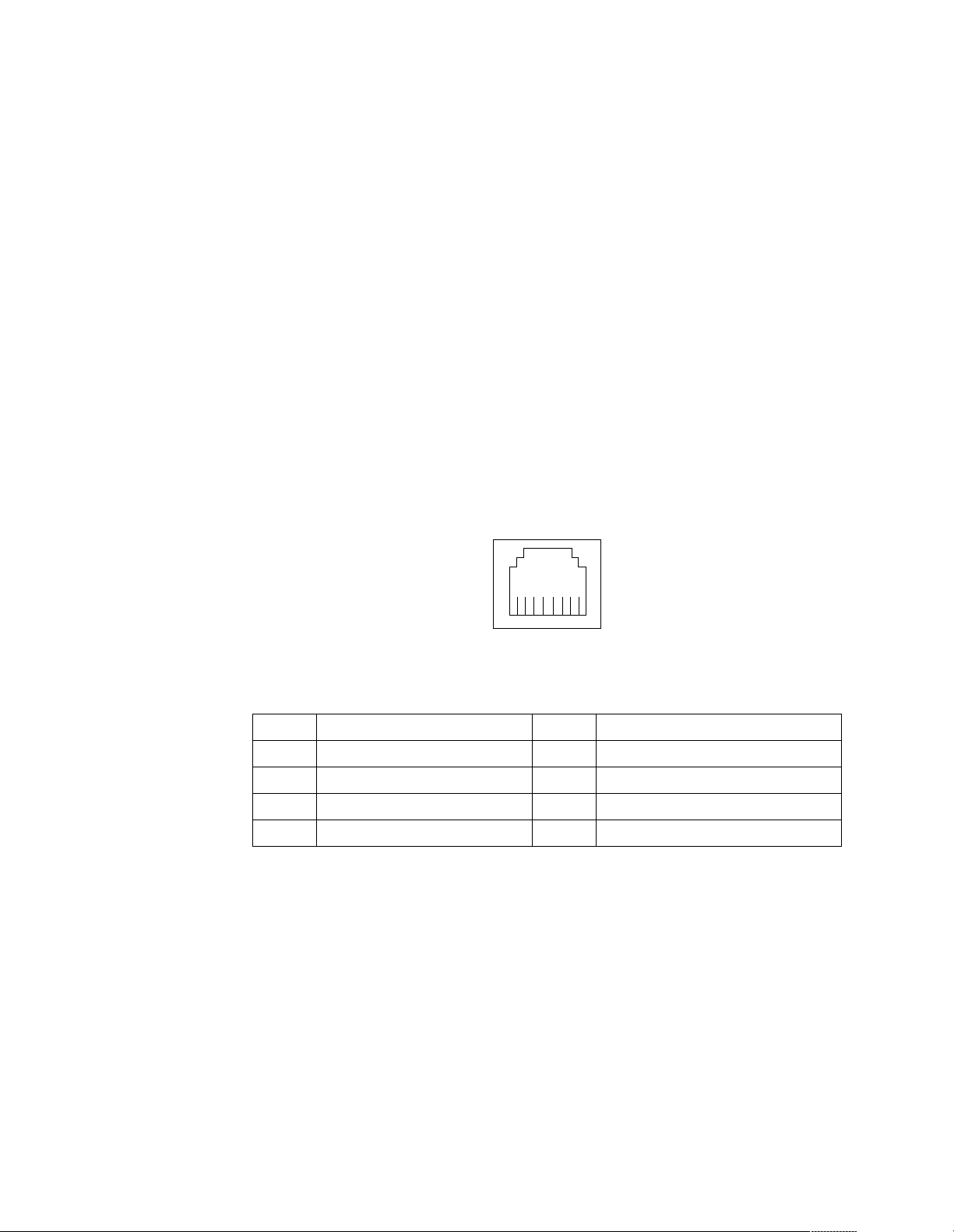
3. In Windows NT, VLANs cannot be implemented on controllers that have been
configured for teaming op tions. NetWare can support team ing options and
VLANs on the sa me adapters.
Complete the following steps to join a VLAN from Windows NT 4.0:
1. Create a VLAN on the switch. Use the parameters you assign there to join the
VLAN from the server. Refer to your switch documentation for more information.
2. Double-click the Network icon in the Control Panel window.
3. On the Adapters tab, select the adapter you want to be on the VLAN and select
Properties.
4. In IBMSet, select Join VLAN. Note that VLANs cannot be assi g ned to adapters
that are already defined to have an adapter teaming option.
5. Enter the VLAN ID and VLAN name. The VLAN ID must match the VLAN ID of
the switch. The ID range is from 1 to 1000. The VLAN name is for information
only and does not need to match the name on the switch.
6. Select Join VLAN. Repeat steps 3 through 5 for each VLAN you want the server
to join. The VLANs you add are listed on the Adapters tab.
7. Select Close and restart the computer.
Ethernet connector: There is an RJ-45 Ethernet connector on the back of the server,
see “I/O connector loca tions” on page 60 for the location of this connector. The
following table shows th e pin-number assignments for the Ethernet con nector.
8
1
Table 11. Ethernet RJ-45 connector pin-number assignments..
Pin Signal Pin Si gnal
1 + Transmit data 5 Not connected
2 - Tra nsmit data 6 - Receive data
3 + Receive data 7 Not connected
4 Not connected 8 Not connected
Universal Serial Bus connectors
Your server has two Universal Serial Bus (USB) connectors, which are configure d
automatically. USB is a serial interface standard for telephony and multimedia
devices. It u ses Plu g an d P la y technology to det erm ine the typ e o f dev i ce tha t is
attached to the connector.
Notes:
1. If you attach a standard (non-USB) keyboard to the keyboard connector, the USB
connectors and devices will be disabled during the power-on self-test.
2. If you install a USB keyboard that has a mouse connector, the USB keyboard
emulates a mouse, and you will not be able to disable the mouse settings in the
Configuration/ Se tup Ut ility program .
68 Hardware Maintenance Manual: xSeries 200
Page 77

USB cables and hubs: Y ou need a 4-pin cable to connect devices to USB 2 or USB 3. If
you plan to attach more than two USB devic e s, you must use a hub to connect the
devices. The hub provide s mu ltiple connectors for attac hing additional e xternal USB
devices.
USB technology transfers data at up to 12 megabits-per-second (Mbps) with a
maximum of 127 external devic e s and a maximum sign al distance of five meters (16
ft) per segment.
USB connectors: There are two USB connectors located on the rear of the server for
attaching USB-co mpatibl e devices, see “I/O connector locations” on page 60 for the
location of the USB connectors. The table below shows the pin-number assignments
for the USB connectors.
14
Table 12. USB connector pin-number assignments.
Pin Signal
1+5 V
2-Data
3+Data
4Ground
Audio connectors
The audio connectors are used to connect external audio equipment to your server,
see “I/O connector loca tions” on page 60 for the location of these connectors.
Line
LineinMic
out
Line out: This connector is use d to send audio signals from the se rver to external
devices, such as powered spea ker s with b uilt -in amp lifiers , headph on es, mult im edia
keyboards, or the audio Line in connector on a stereo system.
Line in: This connector is used to accept audio signals from external devi ces, such as
line output from a stereo, television, or musical instrument into the server sound
system.
Mic: This connector is used to connect a microphone to your server when you want
to record voice or other sounds on the hard disk drive. It might also be used by speech
recognition software.
MIDI connector
The musical instrument digital interface (MIDI) connector allows your server to
interact with musical instru me nts and other musical equipment. You might use the
MIDI connector as an interfac e between y ou r ser ver and a synthesizer to edit and
stor e sou nd information f or the synthesizer on the server. See “I/O connector
Installing options 69
Page 78
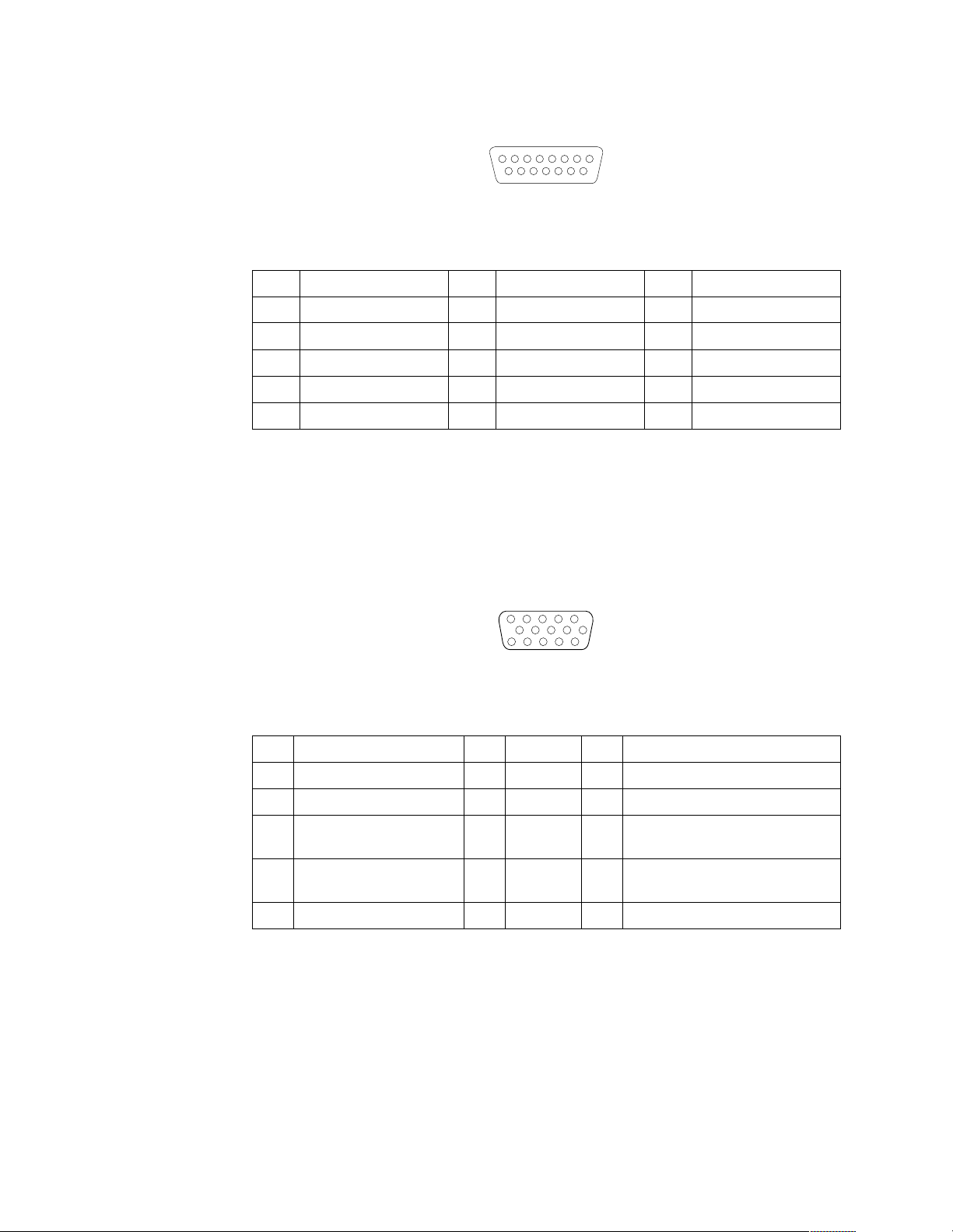
locations” on page 60 for the location of the MIDI connector. The following table
shows the pin-number assignments for the MIDI connector.
8
15 9
1
Table 13. MIDI connector pin-number assignments.
Pin Signal Pin Signal Pin Signal
1 +5 V 6 Joystick 1 -- Y 11 Joysti ck 2 -- X
2 Joystick 1 Sw itch A 7 Joystick 1 Switch B 12 MIDI - OUT
3 Joys tick 1 -- X 8 +5 V 13 Joystick 2 -- Y
4 Switch Common 9 +5 V 14 Joystick 2 Switch D
5 Switches Common 10 Joystick 2 Switch C 15 MIDI - IN
Video connector
Your server uses an AGP adapter located in the AGP slot on the system board. There
is a 15-pin analog video connector located on the rear of the server. See “I/O
connector locations” on page 60 for the location of this connector. The table below
shows the pin-number assignments for the video connector.
5
1
1115
Table 14. Video connector pin-number assignments.
Pin Signal Pin Signal Pin Signal
1Red 6Ground11Not connected
2 Green or monochrome 7 Ground 12 DDC SDA
3 Blue 8 Ground 13 Horizontal sync hronization
(Hsync)
4Not connected 9+5 V dc
DDC
5 Groun d 1 0 Ground 15 DDC SC L
14 Vertical synchronization (V s ync)
Ultra 3/160 SCSI connector (some models)
Some xSeries 200 server models come with a SCSI adapter, which supports a singl e
Ultra 3/160/MB SCSI channel in a full-featured PCI 2.1-/2.2-compliant bus master
package. This c on f i g u ration supports a zero wait st ate, 32-bit memory transfers at 160
Mbytes/second, when LVD SCSI peripherals are attached. This channel supports up
to 15 SCSI devices . In additi on, this adap ter uses:
• Double-transition clocking to achieve high transfer rates
70 Hardware Maintenance Manual: xSeries 200
Page 79

• Domain name validation to negotiate compatible data transfer speeds with each
1
device
• Cyclic-redundancy checking, instead of t he usual parity checking, to significantly
improve data reliability
Note: If you install a RAID adapter, you can move the SCSI signal cable from the
SCSI connector on the SCSI adap ter to an internal channel conne ctor o n the
RAID adapter to control th e internal drives from the RAID adapt er.
SCSI cabling requirements: You can install fi ve internal SCSI dev ices using the SCSI
signal cable that comes with your server. If you plan to attach external SCSI devices,
you must order additional SCSI cables. To select and order the correct cables for use
with external devices, contact your IBM reseller or IBM marketing representative. To
recei ve an indication of SCSI hard disk drive acti vity, you must also connect the SCSI
adapter to the SCSI LED (J3) connector on the system board. See “System and PCI
extender board options connectors” on page 35 f or the location of the SCSI connector.
For information about the maximum length of a SCSI cable b e tween the terminate d
ends of the cable, refer to the American National Standards Institute (ANSI) SCSI
standards. Adhering to these standards will help ensure that your server operates
correctly.
Setting SCSI IDs: Each SCSI device connected to a SCSI controll e r must have a
unique SCSI ID. This ID enab les the SCSI cont roller to iden tify the dev ice a nd en su re
that different devices on the same SCSI channel do not attempt to transfer data
simultaneously. SCSI devices that are connected to differ ent SCSI channel s can have
duplicate SCSI IDs.
To install exter nal SCSI devices, you must first install an optional SCSI PCI adapter.
Refer to the information that is provided with the device for instructions to set its SCSI
ID.
Wi th a SCSI adapter installed in your server, you can use its 68-pin SCSI connector to
connect different types of SCSI devices. The following table shows the pin-number
assignments for the SCSI connector.
34
68
35
Installing options 71
Page 80

Table 15. 68-pin SCSI connector pin-number assignments.
Pin Signal Pin Signal
1 +Data 12 35 -Dat a 12
2 +Data 13 36 -Dat a 13
3 +Data 14 37 -Dat a 14
4 +Data 15 38 -Dat a 15
5 +Data P1 39 -Data P1
6 +Data 0 40 -Data 0
7 +Data1 41 -Data 1
8 +Data 2 42 -Data 2
9 +Data 3 43 -Data 3
10 +Dat a 4 44 -Data 4
11 +Dat a 5 45 -Data 5
12 +Dat a 6 46 -Data 6
13 +Dat a 7 47 -Data 7
14 +Dat a P 48 -Data P
15 Ground 49 Ground
16 DIFFSENS 50 Ground
17 T erm power 51 T erm power
18 T erm power 52 T erm power
19 Reserved 53 Reserved
20 Ground 54 Ground
21 +Attention 55 -Attention
22 Ground 56 Ground
23 +Busy 57 -Busy
24 +Acknowledge 58 -Acknowledge
25 +Reset 59 -Reset
26 +Message 60 -Message
27 +Select 6 1 -Select
28 +Control/Data 62 -Control/Data
29 +Request 63 -Request
30 +Input/Output 64 -Input/Output
31 +Data 8 65 -Data 8
32 +Data 9 66 -Data9
33 +Data 10 67 -Data 10
34 +Data 11 68 -Data 11
72 Hardware Maintenance Manual: xSeries 200
Page 81
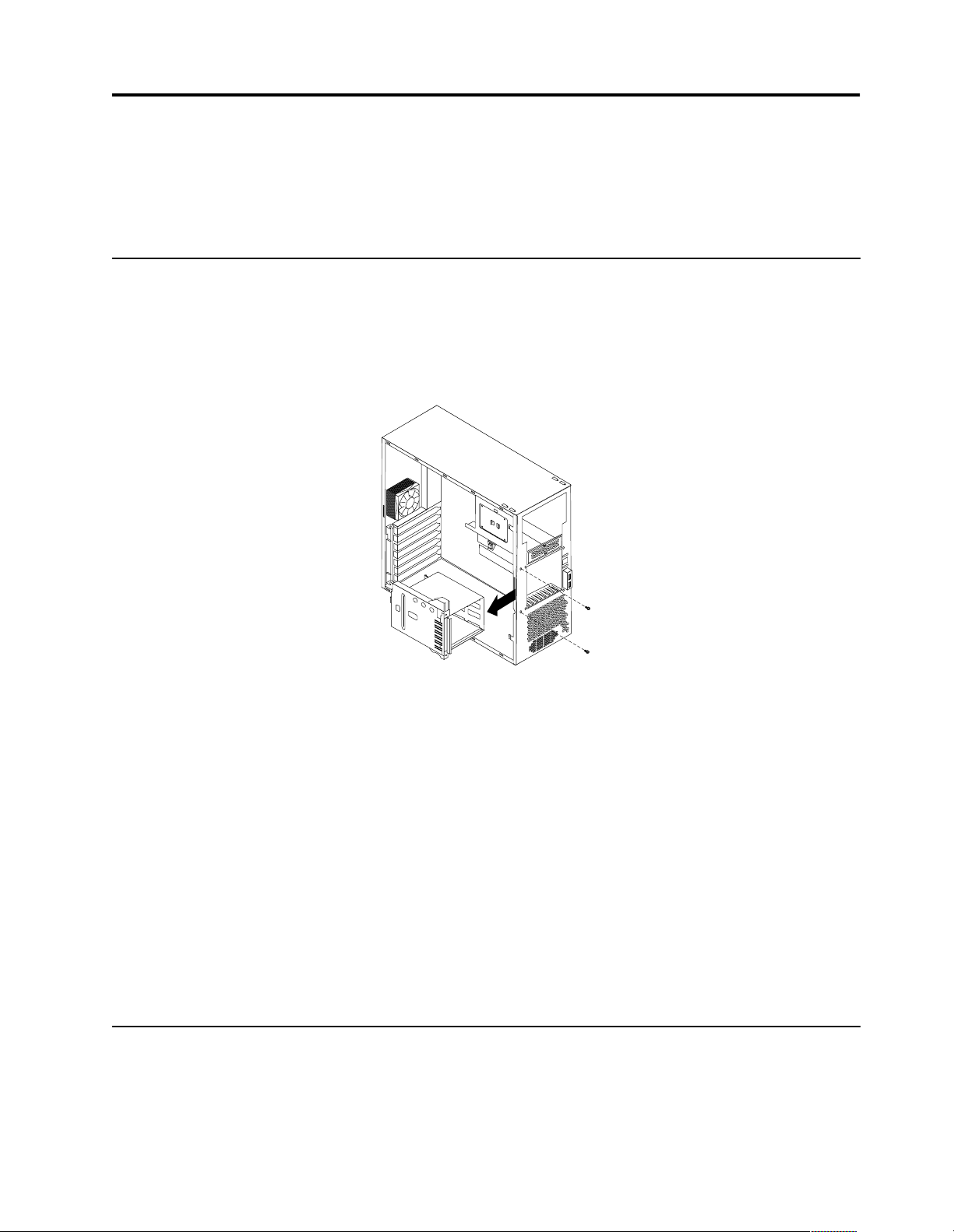
FRU information (service only)
Field Replacement Units (FRUs) should be replaced by qualified service personnel
only.
Har d disk drive cage
Before you begin:
• Read “Safety information” on page 105.
• Review the information in “Before you begin” on page 38.
Power supply
To remove the hard dis k drive cage, do the following:
1. Power-off the se rver, if it is on.
2. Unplug the server.
3. Remove the front bezel (see “Removing the bezel” on page 41).
4. Remove the cover (see “Removing the side cover” on page 40).
5. Remove the support bracket (see “Removing the support bracket assembly” on
page 42).
6. Remove any hard disk drives or drive fillers from the drives.
7. Disconnect the hard disk drive cables from the system board.
8. Remove the screws from the front of the hard di sk drive cage.
9. Move the cage slightly in and up until it is free of the chassis and lift it out of the
server.
Note: Take care not to dislodge th e memory when you remove the cage.
Before you begin:
• Read “Safety information” on page 105.
• Review the information in “Before you begin” on page 38.
© Copyright IBM Corp. 2000 73
Page 82

Rear fan
To remove the power supply, do the following:
1. Power-off the se rver, if it is on.
2. Unplug the server.
3. Remove the cover (see “Removing the side cover” on page 40).
4. Disconnect the power cables from the system board.
5. Remove the screws from the rear o f the server.
6. Gently move the power supply away from the chassis and lift it out of th e server.
Before you begin:
• Read “Safety information” on page 105.
• Review the information in “Before you begin” on page 38.
74 Hardware Maintenance Manual: xSeries 200
Page 83

Rear
Fan
Rubber
extensions
To remove the rea r fa n, do the following:
1. Power-off the se rver, if it is on.
2. Unplug the server.
3. Remove the cover (see “Removing the side cover” on page 40).
4. Remove the support bracket (see “Removing the support bracket assembly” on
page 42).
5. Remove the fan cable from the system board.
6. Use side cutters to se ver the four rubb e r extensions on the outside of the server.
7. Gently pry the fan away from the server and lift it up and out.
8. To install the new fan assembly, place the fan in position at the rear of the server.
9. G uide the rubber extensions through the apertures.
10. Use needle-nosed pliers to pull the extensions through the apertures.
11. Reconnect cables.
System board
Before you begin:
• Read “Safety information” on page 105.
• Review the information in “Before you begin” on page 38.
Note: It is recommended that the server be placed on its left side before performing
this service procedure. Rotate the feet in toward the server so they do not
detach due to the weight of the server.
FRU information (service only) 75
Page 84

To remove the system board, do the following:
1. Power-off the se rver, if it is on.
2. Unplug the server.
3. Remove the cover (see “Removing the side cover” on page 40).
4. Remove the front bezel (see “Removing the bezel” on page 41).
5. Remove the support bracket (see “Removing the support bracket assembly” on
page 42).
6. Disconnect the cables.
7. Remove the adapter cards and both adapter retaining brackets (see “Installing an
adapter” on page 45).
8. Remove the hot-swap hard disk drive cage (see “Hard disk dr ive ca g e ” on page
73).
9. Remove memory modu les (see “Installing memory modules ” on page 52).
10. Remove mic roprocessors and/or terminator cards (see “Removing and installin g
a microprocessor” on page 54).
11. Remove screws and lift the system board out of the server.
CD-ROM drive
Before you begin:
• Read “Safety information” on page 105.
• Review the information in “Before you begin” on page 38.
76 Hardware Maintenance Manual: xSeries 200
Page 85

To remove the CD-ROM drive, do the following:
1. Power-off the se rver, if it is on.
2. Unplug the server.
3. Remove the cover (see “Removing the side cover” on page 40).
4. Disconnect the cables.
5. Remove the screws from the CD-ROM drive cage.
6. Gently slide the CD-ROM drive toward the front of the server and lift it out.
Floppy disk drive
Before you begin:
• Read “Safety information” on page 105.
• Review the information in “Before you begin” on page 38.
To remove the floppy disk drive, do the following:
1. Power-off the se rver, if it is on.
2. Unplug the server.
3. Remove the cover (see “Removing the side cover” on page 40).
4. Disconnect the cables.
5. Remove the screws from the floppy disk drive cage.
FRU information (service only) 77
Page 86

Button kit
6. Gently slide the floppy disk drive toward the front of the server and lift it out.
Before you begin:
• Read “Safety information” on page 105.
• Review the information in “Before you begin” on page 38.
To remove the b u t to n ki t, do the follo wi ng:
1. Power-off the se rver, if it is on.
2. Unplug the server.
3. Remove the cover (see “Removing the side cover” on page 40).
4. Remove the front bezel (see “Removing the bezel” on page 41).
5. Remove the hot-swap hard disk drive (see “Hard disk d rive cag e” on page 73).
6. Disconnect the cable of the button kit from the system board.
7. Place a screwdriver against the bottom release latch of the button kit and gently
press upward and slide the latch through the aperture.
8. G ently pinch together the upper release latches and slide the latches through the
aperture and rem ove the button kit.
Guide assembly / speaker
Before you begin:
• Read “Safety information” on page 105.
• Review the information in “Before you begin” on page 38.
78 Hardware Maintenance Manual: xSeries 200
Page 87

To remove the speaker, do the following:
1. Power-off the se rver, if it is on.
2. Unplug the server.
3. Remove the cover (see “Removing the side cover” on page 40).
4. Remove the front bezel (see “Removing the bezel” on page 41).
5. Remove the support bracket (see “Removing the support bracket assembly” on
6. Remove all adapter cards.
7. Unplug the speaker from the system board.
8. Gently push the two tabs of the adapter guide assembly inward until the
9. Slid e the speak e r up a n d out of the se rver.
Bezel release latch
Before you begin:
• Read “Safety information” on page 105.
• Review the information in “Before you begin” on page 38.
page 42).
assembly is released; lift it up and out of the server.
FRU information (service only) 79
Page 88

Top/side cover
To remove the b ez el release latch, do the follow ing:
1. Power-off the se rver, if it is on.
2. Unplug the server.
3. Remove the cover (see “Removing the side cover” on page 40).
4. Remove the front bezel (see “Removing the bezel” on page 41).
5. Remove the handle assembly (see “Handle assembly” on page 81).
6. Remove the top/side cover (see “Top/ s ide c over”).
7. Press down on the tab.
8. From the underside, grasp the bezel release latch in the center and gently pull it
back and away from the server.
Before you begin:
• Read “Safety information” on page 105.
• Review the information in “Before you begin” on page 38.
80 Hardware Maintenance Manual: xSeries 200
Page 89

To remove th e top/side cove r, do the fol lowing:
1. Power-off the se rver, if it is on.
2. Unplug the server.
3. Remove the cover (see “Removing the side cover” on page 40).
4. Remove the front bezel (see “Removing the bezel” on page 41).
5. Remove the handle assembly (see “Handle assembly”).
6. Remove the four screws from the back of the server and put them in a safe place.
7. Using a screwdriver, gently pry the cover away from the server in the rear and
Handle assemb ly
Before you begin:
• Read “Safety information” on page 105.
• Review the information in “Before you begin” on page 38.
slide the unit away from the server .
FRU information (service only) 81
Page 90

To remove the handle cap, do the following:
1. Power-off the se rver, if it is on.
2. Unplug the server.
3. Use a flathead screwdriver to gently press in and down on the tab s located on the
interior side wall of the hand le.
4. Lift up on the handle cap to separate it from the handle support.
To remove the handle support, do the following:
1. Power-off the se rver, if it is on.
2. Unplug the server.
3. Fir mly grasp the handle support and slide it away from the front bezel.
4. Lift up on the handle support to remove it from the slots in the top of the chassis.
Adapter retainer
Before you begin:
• Read “Safety information” on page 105.
• Review the information in “Before you begin” on page 38.
82 Hardware Maintenance Manual: xSeries 200
Page 91

To remove the adapter retainer, do the following:
1. Power-off the se rver, if it is on.
2. Unplug the server.
3. Remove the cover (see “Removing the side cover” on page 40).
4. Remove all adapter cards (see “Inst alling an adap ter” on page 45).
5. R otate the adapter retainer to the open position.
6. Grasp the adapter retainer and gently slide the top and bottom tabs ou t of th e
notches.
FRU information (service only) 83
Page 92

84 Hardware Maintenance Manual: xSeries 200
Page 93

Symptom-to-FRU index
This index supports xSeries 200 servers.
Notes:
1. Check the configuration be fore you replace a FRU. Configuratio n problem s can
cause false errors and symptoms.
2. Th e default configuration can be loaded by starting the system and then pressing
the reset button four times, waiting 15 seconds between each press. Once the
configur ation has reset to the default, it must be saved in Setup to be stored in
CMOS.
3. For IBM devices not supported by index, refer to the manual for that device.
4. Always start with “Chapter . General checkout,” on page 1.
The Symptom-to-FRU li s ts symptoms, errors, and the possible cause s . The most
likely cause is listed first. Use this Symptom-to-FRU index to help you decide which
FRUs to have available when servicing the computer. The POST BIOS displays POST
error codes and messages on the screen.
Beep symptoms
Beep symptoms are short tones or a series of short tones separated by pauses
(intervals without sound). See the following examples.
Note: One beep after successfully completing POST indicates the system is
functioning properly.
Beeps Description
1-2-3 • One beep
• A pause (or break)
• Two beeps
• A pause (or break)
• Three Beeps
4 Four cont i n uous beeps
Beep/Symptom FRU/Action
1-1-3
(CMOS write/ read tes t
failed)
1-1-4
(BIOS EEPROM
checksum failed)
1-2-1
(Programmable
Interval T imer failed)
1. Battery
2. System Board
1. System Board
1. System Board
© Copyright IBM Corp. 2000 85
Page 94

Beep/Symptom FRU/Action
1-2-2
(DMA initialization
failed)
1-2-3
(DMA page register
write/read failed)
1-2-4
(RAM refresh
verification failed)
1-3-1
(1st 64K RAM test
failed)
1-3-2
(1st 64K RAM parity
test failed)
1-4-3
(Interrupt vector
loading test failed)
1. System Board
1. System Board
1. DIMM
2. System Board
1. DIMM
2. System Board
1. DIMM
2. Processor
3. System Board
1. System Board
2-1-1
(Secon d a r y DMA
register failed)
2-1-2
(Primary DMA register
failed)
2-1-3
(Primary interrupt
mask register failed)
2-1-4
(Secondary interrup t
mask register failed)
2-2-1
(Interrupt vector
loading failed)
2-2-2
(Keyboard controller
failed)
1. System Board
1. System Board
1. System Board
1. System Board
1. System Board
1. System Board
2. Keyboard
2-2-3
(CMOS power failure
and checksum checks
failed)
1. Battery
2. System board
86 Hardware Maintenance Manual: xSeries 200
Page 95

Beep/Symptom FRU/Action
2-2-4
(CMOS configuration
info validation failed)
2-3-1
(Screen initialization
failed)
2-3-2
(Screen memory failed)
2-3-3
(Screen retrace failed)
2-3-4
(Search for video ROM
failed)
2-4-1
(Vi d e o failed, scree n
believed operable)
3-1-1
1. Battery
2. System board
1. Jump e r o n J2 8
2. System Board
1. System board
1. System board
1. System board
1. System board
1. System Board
(Timer tick interrupt
failed)
3-1-2
(Interval timer channel
2 failed)
3-1-3
(RAM test faile d above
address OFFFFH)
3-1-4
(Ti m e-of-Day clock
failed)
3-2-1
(Serial port failed)
3-2-2
(Parallel port failed)
3-2-3
(Math coprocessor
failed)
1. System Board
1. DIMM
2. Memory card
3. System board
1. Battery
2. System Board
1. System board
1. System board
1. Processor
2. System board
3-2-4
(Failure comparing
CMOS memory size
1. DIMM
2. Battery
3. System board
against actual)
Sy mpt om- to -FRU in dex 87
Page 96

Beep/Symptom FRU/Action
3-3-1
(Memory size
mismatch occu rred, se e
"Memory Settings" on
page 31)
3-3-2
(Critical SMBUS error
occurre d) (I2C bus
error)
3-3-3
(No ope rati o n al
memory in system)
Two Short Beeps
(Inform a tion on ly, the
configuration has
changed)
Three Short Beeps 1. DIMM
One Continuous Beep 1. Processor
1. DIMM
2. System board
3. Battery
1. Disconnect the server power cord from outlet, wait 30 seconds and retry.
2. System Board
3. DIMMs
4. Power Supply
5. 12C Cable
1. Install or reseat the memory mo dules, then do a 3 boot reset. (See “Using the
Configuration/Setup Utility program” on page 29.)
2. DIMMs
3. System Board
1. Run Diagnostics
2. Run Configuration/Setup
2. System Board
2. System Board
Repeating Sho rt Beeps 1. Keyboard
2. System Board
One Long and One
Short Beep
One Long and Two
Short Beeps
Two Long and T w o
Short Beeps
1. Video adapter (if present)
2. System Board
1. Video adapter (if present)
2. System Board
1. Video adapter
No beep sym pt oms
No Beep Symptom FRU/Action
No beep and the system
operates cor rectly.
No Beeps occur after
successfully completing
POST
1. Check speaker cables
2. Speaker
3. Syst e m bo ard
1. Check speaker connections
2. Speaker
3. Syst e m bo ard
88 Hardware Maintenance Manual: xSeries 200
Page 97

No Beep Symptom FRU/Action
No ac power 1. Check the power cord.
2. Power supply .
No beep and no video 1. See “Undetermined problems” on page 100
Diagnostic error codes
Note: In the following error codes, if XXX is 000, 195, or 197,do not r epla ce a FRU.
The description for these error codes are:
000 The tes t passed.
195 The Esc key was pressed to abort the te st.
197 This is a warning error and may not indicate a hardware failure.
For all error codes, replace/follow the FRU/Action indicated.
Error Code/Symptom FRU/Action
001-XXX-000
(Failed core tests)
001-XXX-001
(Failed core tests)
001-250-0 00
(Failed System Board ECC)
001-250-0 01
(Failed System Board ECC)
005-XXX-000
(Failed Video test)
011-XXX-000
(Failed COM1 Serial Port test)
011-XXX-001
(Failed COM2 Serial Port test)
014-XXX-000
(Failed Parallel Port test)
1. System Board
1. System Board
1. System Board
1. System Board
1. Video Ada p te r (i f in stalle d)
2. Syst e m B oard
1. System Board
1. System Board
1. System Board
015-XXX-001
(USB interfa ce not fou nd ,
board damaged)
015-XXX-015
(Failed USB External
Loopback test)
Sy mpt om- to -FRU in dex 89
1. System Board
1. Make sure parallel port is not disabled
2. Re-run USB External Loopback test
3. System Board
Page 98

Error Code/Symptom FRU/Action
015-XXX-198
(USB device connected
during USB test)
020-XXX-000
(Failed PCI Interface test)
030-XXX-000
(Failed Internal S CSI interface
test)
030-XXX-00N
(Failed SCSI test on PCI slot
N. Check system error log
before replacing a FRU.)
035-XXX-099 1. No adapters were found.
035-XXX-S99
(Failed RAID test on PCI slot
S. S = number of failing PCI
slot. Check System Error Log
before replacing a FRU.)
1. Remove USB devices from USB1 and USB2
2. Re-run test
3. System Board
1. System Board
1. System Board
1. Adapter in Slot N
2. If adapter is installed re-check conn e ction.
1. Adapter
2. SCSI Backplane
3. Cable
035-XXX-SNN
(Check System Error Log
before replacing a FRU. S =
number of failing PCI slot;
NN = SCSI ID of failing fixed
disk.)
035-253-S99
(RAID adapter initialization
failure)
075-XXX-000
(Failed Power Supply test)
089-XXX-001
(Failed Micr oprocessor test)
180-XXX-003
(Failed System Board LED
test)
201-XXX-0NN
(Failed Memory test, see
"Memory Settings" on page
31.) NN = DIMM location.
1. Fixed Disk with SCSI ID NN on RAID adapter in PCI slot S.
1. ServeRAID Adapter in slot S is not configured properly. Obtain the basic and
extended configuration status and re fer to the ServeRAID Hardware Maintenance
Manual for more informa tion.
2. Cable
3. Adapter
1. Power Supply
1. Microprocessor
1. System Board
1. DIMM Location J1-J4
2. Mem ory card
90 Hardware Maintenance Manual: xSeries 200
Page 99

Error Code/Symptom FRU/Action
201-XXX-999
(Multiple DIMM failure, see
error text.)
202-XXX-001
(Failed System Cache test)
206-XXX-000
(Failed Diskette Drive test)
215-XXX-000
(Failed IDE CD-ROM test)
217-XXX-000
(Failed BIOS Fixed Disk test)
Note: If RAID is
configured, the fixed
disk number re fers to
the RAID logical
array.
217-XXX-001
1. See error text for failing DIMMs
1. Microprocessor CPU 1
1. Cable
2. Diskette Drive
3. Syst e m B oard
1. CD-ROM Drive Cables
2. CD-ROM Drive
3. Syst e m B oard
1. Fixed Disk 1
1. Fixed Disk 2
(Failed BIOS Fixed Disk test)
Note: If RAID is
configured, the fixed
disk number re fers to
the RAID logical
array.
217-XXX-002
(Failed BIOS Fixed Disk test)
Note: If RAID is
configured, the fixed
disk number re fers to
the RAID logical
array.
264-XXX-0NN
(NN = SCSI ID of failing Tape
Drive)
264-XXX-999
(Errors on multiple tape
drives, see error text for more
info)
1. Fixed Disk 3
1. Tape Cartridge, if user executed the Read/Write Tape Drive test (XXX = 256)
2. SCSI or power cable connected to the tape drive with SCSI ID NN
3. T ape drive with SCSI ID NN – refer to Help and Service Information appendix of
tape drive’s User Guide.
4. I/O Legacy Board or SCSI Controller – run SCSI Controller diagnostic to
determine of SCSI bus is functioning properly.
1. See error messages/text in the PC Doctor error log for detailed inform ation on
each indivi dual tape drive error.
Sy mpt om- to -FRU in dex 91
Page 100

Error Code/Symptom FRU/Action
301-XXX-000
(Failed Keyboard test)
405-XXX-000
(Failed Ethernet test on
controller on the Sy s tem
Board)
405-XXX-00N
(Failed Ethernet test on
adapter in PCI slot N)
415-XXX-000
(Failed Modem test)
1. Keyboard
1. Verify that Etherne t is not disabled in BIOS.
2. Syst e m B oard
1. Adapter in PCI slot N.
2. Syst e m B oard
1. Cable
2. Modem
3. Syst e m B oard
Erro r symptoms
General FRU/Action
CD is not working proper ly. 1. Clean the CD.
2. Run CD -ROM d i ag n ostics .
3. CD-ROM Drive
CD-ROM drive tray is not
working.
(The server must be
powered-on.)
CD-ROM drive is not
recognized.
Power switch does not work. 1. Verify that switch number 5 of switch block i s Off.
CD-ROM drive cable is not
plugged in.
1. Insert the end of a pape r clip into the man u al tray-rele ase opening.
2. Run CD -ROM d i ag n ostics .
3. CD-ROM Drive
1. Run Configuration/Setup, enable primary IDE channel.
2. Check cables and jumpers.
3. Check for correct device driver.
4. Run CD -ROM d i ag n ostics .
5. CD-ROM drive
6. Syst e m B oard
2. Power Switch Assembly
3. Syst e m B oard
1. Make sure CD-ROM drive cable is plugged in.
92 Hardware Maintenance Manual: xSeries 200
 Loading...