

Page 1

IBM WebSphere Business Integration Ad apters
A d apter fo r i2 User Guid e
Adapter Version 1. 0.x
Page 2

Page 3

IBM WebSphere Business Integration Ad apters
A d apter fo r i2 User Guid e
Adapter Version 1. 0.x
Page 4

Note!
Before using this information and the product it supports, read the information in Appendix D, “Notices”, on page 77.
18April2003
This edition of this document applies to IBM WebSphere InterChange Server, version 4.2, WebSphere Business
Integration Adapters, version 2.2.0, and to all subsequent releases and modification until otherwise indicated in new
editions.
To send us your comments about this document, email doc-comments@us.ibm.com. We look forward to hearing
from you.
When you send information to IBM, you grant IBM a nonexclusive right to use or distribute the information in any
way it believes appropriate without incurring any obligation to you.
© Copyright International Business Machines Corporation 2002, 2003. All rights reserved.
US Government Users Restricted Rights – Use, duplication or disclosure restricted by GSA ADP Schedule Contract
with IBM Corp.
Page 5

Integration broker compatibility
Supported on IBM WebSphere Business Integration Adapter Framework versions
2.2.0, IBM WebSphere InterChange Server versions 4.1.1 and 4.2, WebSphere MQ
Integrator version 2.1.0, and WebSphere MQ Integrator Broker, version 2.1.0.
See Release Notes for any exceptions.
© Copyright IBM Corp. 2002, 2003 iii
Page 6

iv Adapter for i2 User Guide
Page 7

Contents
Integration broker compatibility .........................iii
About this document .............................vii
Audience ....................................vii
Related documents .................................vii
Typographic conventions ...............................vii
Chapter 1. Overview of the connector .......................1
Connector architecture ................................1
How the connector works ...............................3
Chapter 2. Installing and configuring the connector .................7
Prerequisites for installing the connector ..........................7
Installing the connector on a Windows or UNIX system .....................7
Configuring the connector ...............................8
Starting the connector ................................10
Chapter 3. Understanding business objects for the connector ............11
Defining connector metadata .............................11
Overview of business object structure...........................11
i2 business object structure ..............................12
Specifying business object attribute properties ........................14
Identifying business object application-specific information ...................15
Chapter 4. Generating business objects using i2 ODA ...............17
Overview of i2 ODA ................................17
Installing i2 ODA .................................17
Using i2 ODA in Business Object Designer .........................19
Create the metaobject for polling ............................25
Chapter 5. Troubleshooting and error handling ..................27
Logging error messages ...............................27
Tracing messages .................................30
Tips for troubleshooting ...............................31
Appendix A. Standard configuration properties for connectors ...........33
New and deleted properties ..............................33
Configuring standard connector properties for WebSphere InterChange Server .............34
Configuring standard connector properties for WebSphere MQ Integrator ..............46
Appendix B. Connector Configurator .......................55
Using Connector Configurator in an internationalized environment.................55
Starting Connector Configurator ............................56
Choosing your broker ................................57
Using a connector-specific property template ........................58
Using Connector Configurator with ICS as the broker .....................61
Setting the configuration file properties (ICS) ........................63
Setting the configuration file properties (WebSphere MQ Integrator Broker) ..............68
Using standard and connector-specific properties with Connector Configurator.............71
Completing the configuration .............................72
Appendix C. Connector feature list .......................73
Event notification features ..............................73
© Copyright IBM Corp. 2002, 2003 v
Page 8

Service call request handling features ...........................73
General features ..................................74
Appendix D. Notices ..............................77
Programming interface information ...........................78
Trademarks and service marks .............................78
vi Adapter for i2 User Guide
Page 9

About this document
IBM(R) WebSphere(R) Business Integration Adapters supply integration
connectivity for leading e-business technologies and enterprise applications.This
document describes the installation, configuration, and business object
development for the adapter for i2..
This document describes the installation, configuration, troubleshooting, and
business object development for the connector component of the IBM WebSphere
Business Integration Adapter for i2.
Audience
This document is for consultants, developers, and system administrators who use
the connector at customer sites.
Related documents
The complete set of documentation available with this product describes the
features and components common to all WebSphere Business Integration Adapter
installations, and includes reference material on specific components.
To access the documentation, go to the directory where you installed the product
and open the documentation subdirectory. If a welcome.html file is present, open it
for hyperlinked access to all documentation. If no documentation is present, you
can install it or read it directly online at one of the following sites:
v If you are using WebSphere MQIntegrator as your integration broker:
http://www.ibm.com/websphere/integration/wbiadapters/infocenter
v If you are using InterChange Server as your integration broker:
http://www.ibm.com/websphere/integration/wicserver/infocenter
The documentation set consists primarily of Portable Document Format (PDF) files,
with some additional files in HTML format. To read it, you need an HTML
browser such as Netscape Navigator or Internet Explorer, and Adobe Acrobat
Reader 4.0.5 or higher. For the latest version of Adobe Acrobat Reader for your
platform, go to the Adobe website (www.adobe.com).
Typographic conventions
This document uses the following conventions:
courier font
italic, italic Indicates a new term the first time that it appears, a variable
blue text Blue text, which is visible only when you view the manual
{}
© Copyright IBM Corp. 2002, 2003 vii
Indicates a literal value, such as a command name, file
name, information that you type, or information that the
system prints on the screen.
name, or a cross-reference.
online, indicates a cross-reference hyperlink. Click any blue
text to jump to the object of the reference.
In a syntax line, curly braces surround a set of options from
which you must choose one and only one.
Page 10

|
[]
...
<>
/, \
%text% and $text Text within percent (%) signs indicates the value of the
In a syntax line, a pipe separates a set of options from which
you must choose one and only one.
In a syntax line, square brackets surround an optional
parameter.
In a syntax line, ellipses indicate a repetition of the previous
parameter. For example, option[,...] means that you can
enter multiple, comma-separated options.
Angle brackets surround individual elements of a name to
distinguish them from each other, as in
<server_name><connector_name>tmp.log.
In this document, backslashes (\) are used as the convention
for directory paths. For UNIX installations, substitute slashes
(/) for backslashes. All product pathnames are relative to the
directory where the connector for i2 is installed on your
system.
Windows text system variable or user variable. The
equivalent notation in a UNIX environment is $text,
indicating the value of the text UNIX environment variable.
viii Adapter for i2 User Guide
Page 11

Chapter 1. Overview of the connector
This chapter describes the connector component of the IBM WebSphere Business
Integration Adapter for i2 and the relevant business integration system
architecture.
The i2 connector integrates with i2 application modules through i2’s Common
Integration Services (CIS) API. CIS API from i2 is an implementation of JCA
Common Client Interface. i2 has a suite of application modules that support CIS.
The i2 connector is metadata driven, has object discovery capability, and enables
integration to any version 6.0 SDK CIS-enabled i2 application. Many i2 modules
versions 5.2 and above, support version 6.0 CIS SDK. This connector is available
on Windows, Solaris, and AIX.
Connectors consist of two parts: the application-specific component and the connector
framework. The application-specific component contains code tailored to a particular
application or technology (in this case, i2). The connector framework, whose code
is common to all connectors, acts as an intermediary between the integration
broker and the application-specific component. The connector framework provides
the following services between the integration broker and the application-specific
component:
v Receives and sends business objects
v Manages the exchange of startup and administrative messages
Note: This document contains information about both the connector framework
and the application-specific component. It refers to both of these as the
connector.
For more information about the relationship of the integration broker to the
connector, see IBM WebSphere InterChange Server System Administration Guide or IBM
WebSphere Business Integration Adapters Implementation Guide for MQ Integrator
Broker.
This chapter contains the following sections:
v “Connector architecture” on page 1
v “How the connector works” on page 3
Connector architecture
i2’s Common Integration Service (CIS) enables connectivity between external
applications and i2 application modules.
CIS includes three primary components:
v CIS Front Bus--used by applications to specify an XML metadata format
interface that details the available functions and their expected input and output
data. CIS scripts generate the required representations of input and output data
in an XML schema and Java Beans. Product teams implement these functions by
writing handlers in Java that implement standard CIS interfaces and perform the
required logic. These handlers can deal with data as XML or Java Beans. CIS
infrastructure deploys these interfaces so that the client can invoke this
functionality from a variety of resources.
© Copyright IBM Corp. 2002, 2003 1
Page 12
v CIS Back Bus--used by applications to create a bulk import/export interface for
data transfers.
v CIS Single Sign-On--a standard set of Java interfaces used by Web applications
to authenticate users against a central authentication. store.
The i2 connector interacts with the CIS Front Bus using the CIS Client API
provided by i2 along with its CIS adapters. CIS Client API is the implementation
of JCA Common Client Interface. CIS adapters operate based on CIS metadata
information using the various bindings.
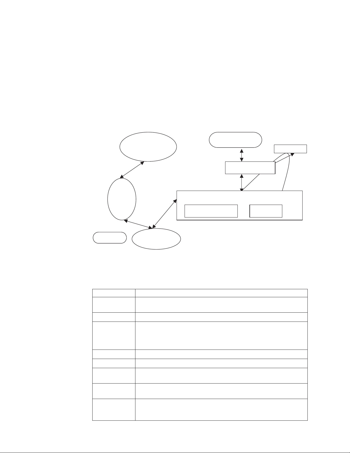
The following diagram shows the i2 connector and components of the i2
framework.
I2 Application
modules
Ex:OM
Integration broker
XML DH
WBIA API
CIS server
I2 connector
Event notification
BOHandler
CIS message
CIS agent
CIS adapter
The following table describes the terminology used for the components of the i2
connector and framework.
Component Description
CIS Common Integration Services provided by i2 to enable connectivity
between the external applications and i2 application modules
OM Order Management, just an example of an i2 application module
CIS agent CIS server application that runs on a central server. It maintains
connection information about client applications and manages and
monitors all the client applications that are part of the solution. The CIS
adapter and i2 application modules register with the CIS agent.
JCA CCI Java Connector Architecture’s Common Client Interface
CIS adapter i2’s CIS Client API and implementation of JCA-CCI
WBIA API API used by the i2 connector to communicate with the designated
integration broker.
integration
broker
XML DH IBM’s data handler (DH) used to transform XML messages to the IBM
A program that handles the execution of the business object processing
logic. Supported brokers are ICS and WMQI.
business objects and vice versa. You need to configure the XML DH for
use with the i2 connector.
2 Adapter for i2 User Guide
Page 13

Component Description
CIS server Integration container which handles operation invocations. Integration
How the connector works
The i2 connector is a CIS (Common Integration Services) client. It connects to the
CIS client API in a non-managed environment, that is, it connects to the CIS
adapter directly without an application server. No authentication is necessary (no
user name or password is required). At present, the CIS client API does not
support any connection pooling mechanism. Hence, connections are created for
every transaction. For information on configuration properties, see “Configuring
the connector” on page 8.
The i2 connector is bi-directional. It can process events originating from i2
applications, as well as requests sent by the broker to the application.
For event subscriptions, the i2 connector uses the information in the i2 metaobjects.
It registers the operations on the types specified in these metaobjects with i2’s CIS
agent. CIS agent listens to the registered operations and detects event messages
only for registered operations. The i2 connector obtains these messages with the
poll call.
container and CIS server are used interchangeably in this document.
For request processing, the i2 connector processes the requests coming from the
integration broker by transforming incoming business objects into CIS records and
using the appropriate CIS Client API calls to execute the operation on the i2
application modules.
The i2 connector follows the metadata design principles outlined in the IBM
Connector Developer’s Guidelines. This means new IBM business objects can be
defined without additional coding or customization at the i2 connector code level.
For more information, see Chapter 3, “Understanding business objects for the
connector”, on page 11.
Processing subscriptions
The following sections describe how the connector processes application events.
Event detection and notification
Events for the purpose of this document are the CIS messages published from the
i2 application modules. The i2 application notifies the connector of all the events
occurring in the modules for which corresponding operations have been registered
with the CIS agent.
The onus of registering the operations of interest lies with the i2 connector.
Example: If the i2 connector is interested in the Bidding type operation addBid,
any new Bidding additions to the i2 application module will be queued in the CIS
server once the i2 connector registers for the addBid operation.
The i2 connector uses the information in the i2 metaobjects. It registers its intent to
listen to some of the operations with the poll call. Effectively, this tells the CIS
agent that the i2 connector wants to check for the output of the registered
operations.
Chapter 1. Overview of the connector 3
Page 14

Status updates
No status updates are made to the i2 applications. Typically, the event status, for
example, SUCCESS, FAIL, UNSUBSCRIBED, is written to the application’s event
store. Since no event store is maintained for i2, the status update strategy is not
relevant for the i2 connector. Error messages, if any, are logged to the i2 adapter
log file. For more information, see Chapter 5, “Troubleshooting and error
handling”, on page 27.
Event retrieval
For the i2 connector, polling is single threaded. The connector uses i2 metaobjects
to register the operations of interest with the CIS agent for polling. These
metaobject names have the i2MO prefix and store information about the operation
and the corresponding IBM wrapper business object name for the specified
operation and type. The attributes for the metaobject are specified as static default
values. Default value is an attribute property, which can be set at the business
object design time. For information on the wrapper business object structure and
attribute properties, see Chapter 3, “Understanding business objects for the
connector”, on page 11 and Chapter 4, “Generating business objects using i2 ODA”,
on page 17.
The steps involved in retrieving a subscription message are as follows:
1. The i2 connector registers the operations with the CIS agent after reading the
i2MO metaobject information. The information in the metaobjects is cached by
the i2 connector with the first poll call.
2. Each poll call is issued from the integration broker based on the connector
property PollFrequency. In case there were any registration failures in the first
poll call, the i2 connector tries to register the same operation with the
subsequent poll calls.
3. With all the poll calls, the i2 connector checks on the output of the operations
that it has registered with the CIS agent. If there is any output from any of the
operations, it retrieves the output in the form of a CIS record. The i2 connector
retrieves the PollQuantity (connector property) number of messages for each
poll call for each registered operation.
Example: If the PollQuantity is set to 5 and there are 5 registered operations,
each poll call will result in checking the output 25 times. If the PollQuantity is
not set, a default of 1 message is retrieved for each poll call for each operation.
4. The retrieved XML message is converted to a business object. The business
object is set as the child attribute in the wrapper business object for the
operation. The instance ID from which this output was retrieved is set as the
instance ID in the metaobject attribute of the wrapper. For more information,
see Chapter 3, “Understanding business objects for the connector”, on page 11.
5. The connector sends the wrapper business object to the integration broker for
further processing.
Processing verbs (operations)
Operations are i2’s equivalent for verbs and are defined by the XML structure
provided by i2 for each port. For more information, see Chapter 3, “Understanding
business objects for the connector”, on page 11, and Chapter 4, “Generating
business objects using i2 ODA”, on page 17.
Processing service call requests
When the i2 connector receives a service call request from an integration broker to
perform an operation in an application, the request takes the form of a wrapper
business object. The wrapper business object encompasses the instance ID
4 Adapter for i2 User Guide
Page 15

metaobject (MO_Instance) and the input and output business objects as its
children. The verb for the wrapper business object must be a valid operation for
the specified instance.
The information about the child business object, whether it is an input or output
type, is obtained from the Application Specific Information (ASI) of the wrapper
business object’s attributes.
Example: ASI Type=input indicates that the child business object is of input type.
The input child business object is first converted to an XML message by the XML
data handler. The business object is then transformed into a CIS record using the
CIS utility. Then the operation is executed using the CIS Client API.
If the operation sends some output XML message, it is converted to an output
child business object; and the output child business object in the wrapper business
object is populated with the appropriate value.
Status updates
Any error conditions that occur while processing are logged as detailed error
messages in the adapter log.
ReturnStatusDescriptor: The connector populates a structure called the
ReturnStatusDescriptor with the message and status of the latest error that
occurred during the processing of a service call request. You can access the
ReturnStatusDescriptor to find the reason for the cause of a failure during a service
call request. The adapter framework propagates the structure, as appropriate.
Chapter 1. Overview of the connector 5
Page 16

6 Adapter for i2 User Guide
Page 17

Chapter 2. Installing and configuring the connector
This chapter describes how to install and configure the connector component of
IBM WebSphere Business Integration Adapter for i2 and how to configure
applications to work with the connector. It contains the following sections:
v “Prerequisites for installing the connector” on page 7
v “Installing the connector on a Windows or UNIX system” on page 7
v “Configuring the connector” on page 8
v “Starting the connector” on page 10
Prerequisites for installing the connector
Before you install the connector, be sure that your system has the required
hardware and software for using the connector.
Required hardware and software:
v Applications:
– CIS SDK 6.0
– J2EE.jar
– Appropriate CIS adapter (MetadataService adapter is required for i2 ODA)
v One of the following application platforms:
– Windows: 2000
– UNIX: Solaris, HP, or AIX
v One of the following adapter platforms:
– Windows: NT, 2000
– UNIX: Solaris 8.0, or AIX 4.3
Note: For instructions on installing the software and installing prerequisites
specific to your integration broker, see IBM WebSphere Business Integration
Adapter Implementation Guide for MQ Integrator Broker; or for InterChange
Server, see IBM WebSphere InterChange Server System Installation Guide for
UNIX or for Windows.
As part of the default software installation, the data handlers are installed to
your system. When you install the i2 connector from Passport Advantage,
the XML data handler is also installed. For the procedures to configure the
data handlers for the connector, see IBM WebSphere Business Integration
Adapter Data Handler Guide.
Installing the connector on a Windows or UNIX system
This section describes how to install the connector on a Windows or UNIX system.
Step for installing the standard files
Before you begin: You need to have WebSphere InterChange Server on your
system.
Perform the following step to install the standard files associated with the i2
connector:
© Copyright IBM Corp. 2002, 2003 7
Page 18

v Run the Installer utility for IBM WebSphere Business Integration Adapters from
the product CD and select the IBM WebSphere Business Integration Adapter for
i2.
The utility allows you to browse and select the directory into which it will
install the connector subdirectories and files. You must install to the
%ProductDir% product directory that you used for your installation of the IBM
WebSphere InterChange Server system. Use the browse button in the Installer to
locate the directory and select it.
Result: The Installer utility copies the standard files into your system.
Tip: After you have installed your business integration system, you can install
additional connectors from the product CD-ROM at any time. To do this, insert the
product CD-ROM, run the installation program, and choose the connectors that
you want to install.
Installed file structure
The following table describes the file structure used by the connector and shows
the files that are automatically installed with Installer.
Notes:
1. This document uses (\) backslashes as the convention for directory paths. For
UNIX installations, substitute slashes (/) for backslashes.
2. All product path names are relative to the directory where the product is
installed on your system.
3. For Windows, Installer adds an icon for the connector file to the IBM
WebSphere Business Integration Adapters menu. For a fast way to start the
connector, create a shortcut to this file on the desktop.
Subdirectory of %ProductDir% Description
connectors\i2 Contains the connector CWi2.jar file, Version 1.0.0, which
has the connector code and the start_i2.bat files (WIN) or
start_i2.sh files (UNIX).
connectors\messages Contains the i2Adapter.txt file for error messages.
repository\i2 Contains the CN_i2.txt file.
connectors\i2\Sample Contains sample files for creating business objects.
For more information on installing the connector component, see one of the
following guides, depending on the integration broker you are using:
v IBM WebSphere InterChange Server System Installation Guide for your platform
(when usingthe WebSphere InterChange Server as the integration broker)
v IBM WebSphere Business Integration Adapters Implementation Guide for MQIntegrator
Broker (when using WebSphere MQIntegrator as the integration broker)
Configuring the connector
Connectors have two types of configuration properties: standard configuration
properties and connector-specific configuration properties. You must set the values
of these properties before running the connector. As you enter the configuration
values, they are saved in the repository.
To configure connector properties, use one of the following tools:
v Connector Designer--if ICS is the integration broker
8 Adapter for i2 User Guide
Page 19

Tip: Access this tool from the System Manager.
v Connector Configurator--if WebSphere MQIntegrator is the integration broker
Tip: Access this tool from the IBM WebSphere Business Integration Adapter
program folder.
For more information about Connector Configurator, see Appendix B,
“Connector Configurator”, on page 55.
A connector obtains its configuration values at startup. During a run-time session,
you may want to change the values of one or more connector properties. Changes
to some connector configuration properties, such as AgentTraceLevel, are dynamic,
taking effect immediately. Changes to other connector properties are static,
requiring component restart or system restart after a change. To determine whether
a property is dynamic or static, refer to the update method column in Connector
Designer.
Standard connector properties
Standard configuration properties provide information that all connectors use. For
detailed information about these properties, see Appendix A, “Standard
configuration properties for connectors”, on page 33.
Note: Because the connector for i2 supports both the ICS and WebSphere
MQIntegrator integration brokers, configuration properties for both brokers
are relevant to the connector.
In addition, the following supplemental information on standard connector
properties applies to i2.
LogAtInterchangeEnd
Tells whether to log errors on the InterChange Server (ICS).
The default value is false.
MessageFileName
Path of the error message file if it is not located in the standard message location
%ProductDir%\connectors\messages. If the message file name is not in a fully
qualified path, the message file is assumed to be located in the directory specified
by the HOME environment variable or the startup parameter user.home.Ifa
connector message file does not exist, the WBIA API message file is used. If that
file does not exist, the InterchangeSystem.txt file is used as the message file.
The default value is i2Adapter.txt.
Connector-specific properties
Connector-specific configuration properties provide information needed by the
connector at run time. They also provide a way of changing static information or
logic within the connector without having to recode and rebuild it.
The following table lists the connector-specific configuration properties for the
connector along with their descriptions and possible values.
Property Description Possible values
ApplicationName Unique name specified for each
connector
Chapter 2. Installing and configuring the connector 9
i2Adapter
Page 20

Property Description Possible values
ApplicationUserName User name for the i2 connection Not used in this release
ApplicationPassword Password for the i2 connection Not used in this release
CISAgentHostName Used when the CIS agent is running on
a remote machine. If it is not set, the
current local host is assumed to have the
CIS agent running. If it is set, the i2
connector establishes a connection with
this remote host.
ExecutionTimeout Time in milliseconds before the call
to i2 application terminates.
PollQuantity Number of messages that will be
retrieved from the client queue; it will be
pollQuantity multiplied by the number
of registered operations.
UseDefaults The connector checks for this value to
look for the default value of the
attributes during request processing.
This is not used by the i2 connector.
String host name
Example: any machine name
like California
Default is 30000
Default is 1
Not required for this connector
Configuring start_i2.bat (for Windows) or start_i2.sh (for UNIX)
You need to add the proper path to the start files for CIS-SDK and j2ee.jar.
Example: The following path information needs to be added to start_i2.bat file:
set I2_CIS_HOME_DIR=C:\i2\CIS\6.0\cis-sdk
set J2EE_PATH=C:\J2EE_JAR
Note: These are just examples. You should change the path information depending
on your local installation.
Configuring DataHandler
You also need to configure the data handler. Set the following values for the child
business object text/xml in MO_DataHandler_Default:
Validation false
ClassName com.crossworlds.DataHandlers.text.xml
UseNewLine false
InitialBufferSize any appropriate value like 2097152
DummyKey 1
Note: The rest of the fields should be blank.
For detailed information about data handler configuration, see IBM WebSphere
Business Integration Adapters Data Handler Guide.
Starting the connector
For information on starting and stopping a connector, see one of the following
documents, depending on the integration broker you are using:
v IBM WebSphere System InterChange Server Installation Guide for your platform
(when using InterChange server as the integration broker)
v IBM WebSphere Business Integration Adapters Implementation Guide for MQIntegrator
(when using WebSphere MQIntegrator Broker as the integration broker)
10 Adapter for i2 User Guide
Page 21

Chapter 3. Understanding business objects for the connector
This chapter describes the structure of i2 business objects, how the connector
processes the business objects, and the assumptions the connector makes about
them. Use this information as a guide to modifying existing business objects for i2
or as suggestions for implementing new business objects.
The chapter contains the following sections:
v “Defining connector metadata” on page 11
v “Overview of business object structure” on page 11
v “i2 business object structure” on page 12
v “Specifying business object attribute properties” on page 14
v “Identifying business object application-specific information” on page 15
For information on the Object Discovery Agent (ODA) utility that automates the
creation of business objects for the IBM WebSphere Business Integration Adapter
for i2, see Chapter 4, “Generating business objects using i2 ODA”, on page 17.
Defining connector metadata
The i2 connector is metadata-driven. In the WebSphere business integration system,
metadata is application-specific information that is stored in a business object and
that helps the connector interact with the application. A metadata-driven connector
handles each business object that it supports based on the metadata encoded in the
business object definition rather than on instructions hardcoded in the connector.
Business object metadata includes the structure of the business object, the settings
of its attribute properties, and the content of its application-specific information.
Because the connector is metadata-driven, it can handle new or modified business
objects without requiring modifications to the connector code.
The connector makes assumptions about the structure of its supported business
objects, the relationships between parent and child business objects, and the format
of the application-specific information.
Therefore, when you create or modify a business object, your modifications must
conform to the rules the connector is designed to follow, or the connector will not
be able to process new or modified business objects correctly.
Overview of business object structure
In the WebSphere business integration system, a business object definition consists
of a type name, supported verbs, and attributes. An application business object is
an instance of a business object definition. It reflects a specific application’s data
structure and attribute properties.
Some attributes, instead of containing data point to child business objects or arrays
of child business objects that contain the data for these objects. Keys relate the data
between the parent record and child records.
WebSphere Business Integration Adapter business objects can be flat or
hierarchical. A flat business object only contains simple attributes, that is, attributes
that represent a single value (such as a String) and do not point to child business
© Copyright IBM Corp. 2002, 2003 11
Page 22

objects. A hierarchical business object contains both simple attributes and child
business objects or arrays of child business objects that contain the values.
A cardinality 1 container object, or single-cardinality relationship, occurs when an
attribute in a parent business object contains a single child business object. In this
case, the child business object represents a collection that can contain only one
record. The type of the attribute is the same as that of the child business object.
A cardinality n container object, or multiple-cardinality relationship, occurs when
an attribute in the parent business object contains an array of child business
objects. In this case, the child business object represents a collection that can
contain multiple records. The type of the attribute is the same as the type of the
array of child business objects.
A hierarchical business object can have simple attributes and can also have
attributes that represent a single-cardinality child business object or an array of
child business objects. In turn, each of these business objects can contain
single-cardinality child business objects and arrays of business objects, and so on.
In each type of cardinality, the relationship between the parent and child business
objects is described by the application-specific text of the key attribute of the child
object.
i2 business object structure
The i2 IBM business object is the IBM representation of the i2 message. Each type
of message has a corresponding IBM business object.
The business objects are generated using the WebSphere Business Integration
Adapter utility XML ODA, which reads the XML schema files for these types and
generates the corresponding IBM business object. (See Chapter 4, “Generating
business objects using i2 ODA”, on page 17 and Chapter 3, ″XML data handler″ in
IBM WebSphere Business Integration Adapters Data Handler Guide.)
The i2 business object is a wrapper business object that encapsulates a metaobject,
an operation, and input and/or output data (one or the other, both, or none) types
for the operation. There is one wrapper business object for each operation. For
more information, see Chapter 4, “Generating business objects using i2 ODA”, on
page 17.
The following diagram shows the parts of a wrapper business object. A description
of each part follows the diagram.
Wrapper BO
Supported Verb=
Operation
Metaobject (MO Instance)
Input type BO
Output type BO
v The metaobject embedded within the wrapper is used to configure the instance
12 Adapter for i2 User Guide
ID. For more information, see “Configuring metaobjects for polling” on page 13.
Page 23

v The operation is set as the verb on the wrapper business object and is associated
with a port. i2 does not have standard verbs. If multiple operations have the
same set of input and output types, but are supported on different ports, there
will be two different wrapper business objects for the different ports.
v The types are business object attributes which represent data types for an
operation.
The following diagram illustrates a sample business object IBM_Bidding_BO,
which has three child business objects. In the diagram:
v IBM_OptParams and IBM_OptimizationResults represent the top level business
object generated by the XML ODA.
v The application-specific information for the business object is in the Port
(Bidding) and Types (input--IBM_OptParams and output--
IBM_OptimizationResults) attributes.
v The operation is addBid.
v The child business objects are:
– IBM_OptParams, which has two attributes--LaneId and Price
– IBM_OptimizationResults, which has one attribute--WinningBid
– MO_Instance, which has one attribute--InstanceId
IBM_Bidding_BO
Port=Bidding
IBM_OpParams
Type=input
IBM_OptimizationResults
Type=output
MO_Instance
Verb=addBid
IBM_OptParams
LaneId
Price
Configuring metaobjects for polling
The connector uses i2 metaobjects to register its interest in specific operations with
the CIS agent so that polling can take place. You need to configure one metaobject
for each operation of interest.
The metaobject name always starts with i2MO. Each metaobject holds information
about the instance that supports the operation and the wrapper business object
name for the operation. You need to add a dummy verb to all the metaobjects.
The attributes (instance ID, wrapper business object name, and operation name)
within the metaobjects have a static default value. For registering the same
operation on a different instance, you either have to change the default value and
restart the i2 instance or configure another metaobject for the new instance.
IBM_OptimizationResults
WinningBid
MO_Instance
InstanceId
In the following diagram, the metaobject named i2MO_AddBid is used to
configure the instance ID CA_Instance, for the Bidding operation addBid, which is
set on the wrapper business object named IBM_Bidding_BO. The values shown are
default values for the attributes.
Chapter 3. Understanding business objects for the connector 13
Page 24

I2MO_AddBid
InstanceId=CA_Instance
WrapperBOName=IBM_Bidding_BO
Verb=Dummy
Specifying business object attribute properties
The i2 connector has various properties that you can set on its business object
attributes. This section describes how the connector interprets several of these
properties and describes how to set them when modifying a business object.
The following table shows the properties for simple attributes.
Attribute Description
Name Unique name of the attribute
Type All simple attributes should be of type String.
MaxLength Not used
IsKey Each business object must have at least one key attribute, which you
specify by setting the key property to true for an attribute. The i2
connector does not check for this property.
IsForeighKey Not used.
Is Required Set to true if the attribute must have a value in the outgoing XML
message.
AppSpecInfo Not used
DefaultValue Specifies a default value that the connector uses for a simple attribute in
the inbound business object if the attribute is not set and is a required
attribute.
The following table shows the properties for child object attributes.
Attribute Description
Name Name of the child object.
Type Business object type for the child.
Contained
ObjectVersion
Relationship If the child is a container attribute, this is set to Containment.
IsKey Not used
IsForeighKey Not used.
Is Required For relationship details between XML elements and requiredness, see
14 Adapter for i2 User Guide
Rule: You must set and use the default value for the attributes of the
polling metaobjects and MO_Instance metaobject. If the default value is
set for the instance ID, and no value is set in the incoming business
object, the connector takes the default value and tries to connect with
this instance.
For all attributes that represent child business objects, this property
specifies the child’s business object version number.
Chapter 3, ″XML data handler,″ in IBM WebSphere Business Integration
Adapters Data Handler Guide.
Page 25

Attribute Description
AppSpecInfo For information on this property, see “Identifying business object
application-specific information” on page 15,
Cardinality For relationship details between XML elements and cardinality, see
Chapter 3, ″XML data handler,″ in IBM WebSphere Business Integration
Adapters Data Handler Guide.
Special attribute values
Simple attributes in business objects can have the special value, CxIgnore. When it
receives a business object from the integration broker, the connector ignores all
attributes with a value of CxIgnore. It is as if those attributes were invisible to the
connector. No XML is generated for them.
Because the i2 connector requires at least one primary key attribute to create a
business object, you need to ensure that business objects passed in to the connector
should have at least one primary key that is not set to CxIgnore.
Additionally, The i2 connector assumes that no attribute of business object type has
a value of CxBlank. Simple (String) attributes with a value of CxBlank are included
in an XML document. Empty double quotation marks (″″) in an XML document are
used as the PCDATA equivalent of CxBlank.
Identifying business object application-specific information
Application-specific information provides the connector with applicationdependent instructions on how to process business objects. If you extend or modify
an application-specific business object, you must make sure that the
application-specific information in the business object definition matches the syntax
that the connector expects.
Application-specific information at the business object- level
The following table provides application-specific information at the business
object-level for the wrapper business object supported by the i2 connector.
Parameter Description
Port= The name of the i2 port type for the operation.
Application-specific information at the attribute level
The following table provides application-specific information at the attribute level
for the wrapper business object supported by the i2 connector.
Parameter Description
Type= The type represented by the attribute at the wrapper business object
attribute level. The type could be input or output representing the input
and output for the operation.
Chapter 3. Understanding business objects for the connector 15
Page 26

16 Adapter for i2 User Guide
Page 27

Chapter 4. Generating business objects using i2 ODA
This chapter describes i2 ODA, an object discovery agent (ODA), which, working
with XML schema ODA, generates business objects for the IBM WebSphere
Business Integration Adapter for i2.
This chapter contains the following sections:
v “Overview of i2 ODA” on page 17
v “Installing i2 ODA” on page 17
v “Using i2 ODA in Business Object Designer” on page 19
Overview of i2 ODA
i2 Object Discovery Agent (ODA) is a utility to use to obtain the specifications for
the i2 business object from the metadata information in i2’s CIS registry. The
Business Object Development wizard automates the process. You can view or make
modifications to the business object before saving it to the server.
The process for generating an i2 business object has three distinct stages:
1. Identifying the ports, operations, and types for which i2 ODA generates the
schema files; generating the XML schema for the types; and generating the
wrapper business object representing the operations with the types as
attributes.
2. Processing the i2 generated XML schema files and converting the XML schema
to the actual business object for the type.
3. Prior to saving the wrapper business object, saving to the repository the
MO_Instance business object and the business objects that were generated for
the types using XML ODA.
For details, see “Steps for using i2ODA” on page 20.
Installing i2 ODA
This section describes how to install and launch i2 ODA, run multiple instances of
i2 ODA, and work with error and trace message files.
Steps for installing i2 ODA
Before you begin: This chapter assumes you have already installed the i2
connector, as well as the required software for using the connector (see Chapter 2,
“Installing and configuring the connector”, on page 7). Be sure you are using i2
application version 6.0 and i2 ODA 1.0.0.
To install i2 ODA, use the Installer for IBM WebSphere Business Integration
Adapters. Follow the instructions in IBM WebSphere Business Integration Adapters
Implementation Guide for MQIntegrator or for InterChange Server (ICS),orIBM
WebSphere Business Integration System Installation Guide for UNIX or for Windows.
When the installation is complete, the following files are installed in the directory
on your system where you have installed the product:
v ODA\i2\i2ODA.jar
v ODA\messages\i2ODAAgent.txt
© Copyright IBM Corp. 2002, 2003 17
Page 28

v ODA\i2\start_i2ODA.bat (Windows only)
v ODA/i2/start_i2ODA.sh (UNIX only)
Notes:
1. Except as otherwise noted, this document uses backslashes (\) as the
convention for directory paths. For UNIX installations, substitute slashes (/) for
backslashes.
2. All product path names are relative to the directory where the product is
installed on your system.
Other installation requirements
v i2 provides the MetadataService adapter to obtain the metadata information
from the registry. You need to install this adapter on an instance of the i2
application. Be sure to start the adapter prior to using the MetadataService.
v The bindings file for the port MetadataService, for example, TDMMetadata.xml,
which contains the port, operation, and type information, needs to be in the i2
configuration directory.
v The Visibroker Object Activation Daemon needs to run on the machine that is
running the agent and the one on which Business Object Designer is installed.
Launching i2 ODA
Before you begin: Ensure that the i2 ODA and XML schema ODA are installed on
your system.
You can launch i2 ODA in either of the following ways:
v Automatically—If you registered i2 ODA with the Visibroker Object Activation
Daemon (OAD), you do not need to start i2 ODA manually. OAD maintains a
list of registered ODA names and listens for requests to start the ODA. When
you select the ODA’s name in Business Object Designer, OAD starts the ODA.
For information on registering i2 ODA, see IBM WebSphere System Installation
Guide for UNIX or for Windows.
v Manually—If you have not registered i2 ODA with the Visibroker Object
Activation Daemon, start it by running the appropriate file:
UNIX: start_i2ODA.sh
Windows: start_i2ODA.bat
You have to add the proper path to the start files for CIS-SDK and j2ee.jar
Example: The following path information needs to be added to start_i2.bat file:
set I2_CIS_HOME_DIR=C:\i2\CIS\6.0\cis-sdk
set J2EE_PATH=C:\J2EE_JAR
Note: These are just examples. You should change the path information
depending on your local installation.
You configure and run i2 ODA using Business Object Designer. Business Object
Designer locates each ODA by the name specified in the AGENTNAME variable of
each script or batch file. The default ODA name for this connector is i2ODA.
During installation, if you register the ODA with the Visibroker Object Activation
Daemon, the wizard automatically prefixes the host name to the AGENTNAME
value to make it unique.
18 Adapter for i2 User Guide
Page 29

Working with error and trace message files
Error and trace message files (the default is i2ODAAgent.txt) are located in
\ODA\messages\, which is under the product directory. These files use the following
naming convention:
AgentNameAgent.txt
Example: If the AGENTNAME variable specifies i2ODA1, the tool assumes that the
name of the associated message file is i2ODA1Agent.txt
You can have a message file for each ODA instance or have differently named
ODAs use the same message file. The name of the message file is specified in
Business Object Designer as part of ODA configuration.
Note: Failing to correctly specify the message file’s name when you configure the
ODA causes it to run without messages. For more information on specifying
the message file name, see “Configure agent properties” on page 20.
During the configuration process, you specify:
v The name of the file into which i2 ODA writes error and trace information
v The level of tracing, which ranges from 0 to 5
The following table describes the tracing levels.
Trace Level Description
0
1 Traces all entering and exiting messages for method
2 Traces the ODA’s properties and their values
3 Traces the names of all business objects
4 Traces business object properties and the values received
5
v Logs errors and fatal errors from the i2 ODA application
v Logs warnings that require a system administrator’s attention
v Indicates the ODA initialization values for all of its properties
v Traces the business object definition dump
For information on where to configure these values, see “Configure agent
properties” on page 20.
Using i2 ODA in Business Object Designer
This section describes how to use i2 ODA in Business Object Designer to generate
business objects. For information on launching Business Object Designer, see IBM
WebSphere Business Integration Adapters Business Object Development Guide.
After you launch an ODA, you must launch Business Object Designer to configure
and run it. Business Object Designer provides a wizard that guides you through
six steps to generate a business object definition using an ODA. The six steps are
as follows:
1. Select the agent.
2. Configure agent properties.
3. Expand nodes and select port types, operations, and input/output types.
4. Confirm selection, generate wrapper business objects, and save.
Chapter 4. Generating business objects using i2 ODA 19
Page 30

5. Complete the business object and generate the business objects for the types.
6. Save the business object files.
Details for each step follow.
Steps for using i2ODA
Before you begin: You need to start the i2 Business Object Designer wizard.
1. Open Business Object Designer.
2. From the File menu, select New Using ODA....
Result: Business Object Designer displays the first window in the wizard,
named Select Agent.
Perform the following steps:
Select the Agent
To select the ODA:
1. Click Find Agents to display all registered or currently running ODAs in the
Located agents field.
2. Select the desired ODA from the displayed list.
Note: The ODA for i2 has a default name of i2ODA. The agent name depends
on the value of the i2 variable in the start_i2ODA.bat or start_i2ODA.sh
file.
Recommendation: When you run multiple instances of the ODA utility, you
should change the default name by creating a separate batch file for each
instance or by specifying a unique name in the AGENTNAME variable of each
batch file.
When multiple instances of the ODA are running on different machines, they
are visible in the Business Object Designer by their i2 ODA values. If two
ODAs have the same i2 value, then either of the ODAs can be used, with
possibly undesirable results. You can assign unique names to such ODAs by
prefixing the i2 name with the host machine name, or by using an ORB finder
(for example, osfind) to locate existing CORBA object names on your network.
If the ODA is registered with an Object Activation Daemon by the ODA
configuration wizard, the latter prefixes the host name to the AGENTNAME
value, making it unique.
Result: Business Object Designer displays your selected agent in the Agent’s
name field.
Configure agent properties
The first time Business Object Designer communicates with i2 ODA, it prompts
you to enter a set of initialization properties. You can save these properties in a
named profile so that you do not need to re-enter them each time you use i2 ODA.
For information on specifying an ODA profile, see IBM WebSphere Business
Integration Adapters Business Object Development Guide.
In addition to configuring these one-time properties, you need to configure
properties to connect to the CIS agent and to define the tree nodes.
The following table describes the properties to configure.
20 Adapter for i2 User Guide
Page 31

Row
number
1 DefaultBOPrefix String Text that is prepended to the name of the business object
2 SchemaFileLocation String Path where the generated.xsd files are stored. This is
3 MessageFile String Path to the error and message file. If the file is not
4 CISAgentHostName String Host name of the CIS agent, it is specified if the CIS agent
Property name Property type Description
to make it unique.
Example: i2_BO
mandatory; you must specify the path to store the schema
files.
specified, the error messages from the ODA are not
displayed. i2 ODA displays the file name according to the
naming convention.
Example: If the agent is named i2ODA, the value of the
message file property displays as i2ODAAgent.txt.
is running on a remote machine.
You can also configure several optional parameters for the agent when it starts up.
v TraceFileName--File into which i2 ODA writes trace information. The command
line option for this parameter is -t. i2ODA names the file according to the
naming convention.
Example: If the agent is named i2ODA, it generates a trace file named
i2ODAtrace.txt.
v TraceLevel--Level of tracing enabled for i2 ODA. For more information, see
“Working with error and trace message files” on page 19.
Expand nodes and select port types, operations, and
input/output types
i2 ODA uses the properties you configured in the preceding step to connect to the
specified i2 application. Business Object Designer displays the metadata
information about the registered ports, operations for each port, and the input and
output types for each operation as a tree structure. You can expand the tree nodes
for the ports and operations by right-clicking on a node. The type node is the leaf
node of the tree, so it is not expandable.
The following diagram shows a tree view with expanded nodes.
Chapter 4. Generating business objects using i2 ODA 21
Page 32

Metadata (Top tree node) (Expanding Metadata lists all the port types)
PortType1(Child tree nodes)
Operation1
Input type
Output type
Operation..n
Input type
Output type
PortType2
Operation
Input type
v Select the port, operation, and type for generating the business object. Each
operation has an input and output type on a port, and each of these types needs
to have a corresponding business object.
Result: i2 ODA will create the schema file for the chosen type. The schema files
form the input for the XML schema ODA to generate the corresponding business
objects. The XML schema file name follows the naming convention,
input/output_operation_type.
Example: For the persistOrder operation, both the input type and output type is
Order, but the formats for the two are different. i2 ODA validates these and
generates different schema files for the input and output types:
v i2BO_in_persistorder_Order.xsd (input)
v i2BO_out_persistorder_Order.xsd (output)
The schema files are stored in the directory specified by the SchemaFileLocation
property for the ODA. The i2 ODA checks the schema location for the existence of
the schema prior to creating the new one. If there already exists an xsd for the
type, the i2 ODA does not duplicate the schema.
Confirm selection, generate wrapper business object, and save
1. Confirm the operations you have selected for i2 ODA to generate wrapper
business objects.
Result: The i2 ODA creates a wrapper business object to represent the
operation with the chosen port type. Each operation has one wrapper business
object. The input and output types of the operation form the attributes of this
wrapper business object, with the operation as the verb. The port type becomes
the application-specific information for this business object.
The name of the wrapper business object is DefaultBOPrefix_operation. The
wrapper business object contains:
22 Adapter for i2 User Guide
Page 33

v Port information
v Instance ID
v Dummy key (as the business object creation will fail without a key)
v Two single cardinality attributes representing the input and output types for
the operation. The attributes are named as BOPrefix_in_operation_type and
BOPrefix_out_operation_type.
Example: The wrapper BO for the operation persistOrder is i2BO_persistOrder.
i2bo_persistorder
Port=TDM
MO_Instance
InstanceId
Default Value=prapulla2k
DummyKey
i2bo_in_persistorder_order
Type-input
i2bo_out_persistorder_order
Type=output
2. Save the wrapper business object to a file. Saving it to the InterChange server
will fail because the corresponding dependent attribute business objects have
not yet been created by the XML ODA schema.
Guideline: When you save the business objects into a file in this step, the
current Business Object Designer wizard looks at the machine where the agent
is running. Another pop-up window prompts you for a location to save the
generated wrapper business objects.
Complete the business object and generate the business objects
for the types
1. Check the property values that Business Object Designer displays in the BO
Properties window. If you are satisfied with the value you previously entered
in the Configure Agent window (for example, for DefaultBOPrefix), you do not
need to change the value here.
2. Be sure the XML schema ODA agent is running.
a. The XML schema ODA reads the schema files previously saved to the
SchemaFileLocation and generates the business objects for the input and
output types.
b. Save these business objects to the same directory as the wrapper business
objects.
Guideline: The BOPrefix for the XML schema ODA should be the same as
the BOPrefix for the i2 ODA.
Chapter 4. Generating business objects using i2 ODA 23
Page 34

The following diagram shows the business object that the XML schema
ODA generates for i2_order.xsd. The XML data handler uses the
combination of the element next to CISDocument and BOPrefix to get the
business object name.
I2BO_order
XMLDeclaration
I2BO_TLO_CISDocument_Order (1 card)
CISDocument
I2BO_CISDocument_Order
OrderId
SystemId
Save the business object files
Now that all the required business objects are generated, you need to save them to
the InterChange server for use by the collaborations. Use the Business Object
Designer utility to copy the business objects to the server. You can concatenate the
files together into a single file and copy them to the server.
Guideline: Be sure to run the XML schema ODA prior to saving the wrapper
business objects to the server.
Example:
Property Value
FileName D:\i2\odaschema\i2persist_in_persistOrder_Order_Order.xsd
Root CISDocument
TopLevel in_persistOrder_Order
BOSelection false
BOPrefix i2persist
DoctypeorSchemaLocationtrue
TraceFileName XMLODAtrace.txt
TraceLevel 5
MessageFile XMLODAAgent.txt
At this stage, you can decide whether to run different operations on different
instances. You can clone the MO_Instance and set a default value for the instance
ID on these. You will need to replace the default MO_Instance with the newly
created ones in the wrapper business objects for the operations.
24 Adapter for i2 User Guide
Page 35

Create the metaobject for polling
Once the business objects are created, you need to create the metaobjects for
polling using the CSM. These objects shall have the i2MO prefix followed by the
operation. The attributes need to have a default value. This information is used
during polling to register the specific operation and check the output from i2
applications for the registered operation.
The following diagram shows the structure of the i2 metaobject for i2
MO_Operation. The diagram shows the attributes of the metaobject--the instance
ID, operation, and business object wrapper name.
I2MO_Operation
InstanceId
DefaultValue=
WrapperBOName
DefaultValue=
For more information on configuring metaobjects, see Chapter 3, “Understanding
business objects for the connector”, on page 11.
Chapter 4. Generating business objects using i2 ODA 25
Page 36

26 Adapter for i2 User Guide
Page 37

Chapter 5. Troubleshooting and error handling
This chapter describes how the i2 connector for i2. handles errors. The connector
generates logging and tracing messages. The chapter contains the following
sections:
v “Logging error messages” on page 27
v “Tracing messages” on page 30
v “Tips for troubleshooting” on page 31
Logging error messages
The connector logs an error message whenever it encounters an abnormal
condition during processing, regardless of the trace level. When such an error
occurs, the connector also prints a textual representation of the failed business
object as it was received. It writes the text to the i2 Adapter log file, whose file
name corresponds to the connector property LogFileName.
The message contains a detailed description of the condition and the outcome and
may also include extra information that may aid in debugging, such as business
object dumps or stack traces (for exceptions).
Error types: Error messages are of two types:
v Errors--conditions that the connector can recover from, usually by abandoning
the current processing.
v Fatal errors--unrecoverable error conditions. See the following sections on
polling-related and request processing errors.
Structure of error messages
All the error messages that the connector generates are stored in a message file
named i2Adapter.txt. Each error message typically has a message ID, the error
message, and an explanation section for a detailed description and tips to rectify
the problem.
Message ID
Message
[EXPL]
The message IDs for the i2 connector range from 90000 to 92000, with 90000 to
91000 set aside for polling-related error messages, and 91000 to 92000 set aside for
request processing error messages.
Example: The following exemplifies the message structure, where nnnnn represents
the message ID.
nnnnn
Not able to get a connection for this instance {1}.
[EXPL]
Please ensure that the instance specified is up.
{1}--Parameter to the error message, in this case the instance id.
© Copyright IBM Corp. 2002, 2003 27
Page 38

Polling-related error messages
The following table describes polling-related error messages. These are logged in
the i2 Adapter log file.
Notes:
1. In some cases, the connector logs a fatal error (log message type of
XRD_FATAL) so that e-mail notification can be triggered. For logging this error
with the integration broker, you need to set the connector property
LogAtInterchangeEnd to true.
2. E-mail notification will be sent only if the e-mail connector is configured.
Error description Error type Handling by i2 connector
Connection lost while polling Fatal error The connector detects the connection
Not able to register an
operation with the CIS Agent
No metaobjects configured for
polling
Default value for the metadata
object attributes not set
Not able to fetch the message
from CIS Agent
Fatal error With subsequent poll calls, the i2
Error The i2 connector always returns a
Error For details on the default value
Error/SUCCESS In case the poll call to the i2
error at the time of a poll call. It logs a
fatal error (log message type of
XR D_FATA L) and dum ps the XML
message. Fatal error can trigger e-mail
notification. For logging this error
with the integration broker, you need
to set the connector property
LogAtInterchange to true and
continue with polling on other
operations that might be running on
instances that are active.
connector tries to re-register the
operations that could not be registered
with the previous poll call. In case
registering all the operations fail, we
assume that the CIS agent is down;
the connector returns
APPRESPONSETIMEOUT which shuts
down the i2 connector.
FAIL after logging that the metaobjects
are not configured for polling.
attribute property, see Chapter 3,
“Understanding business objects for
the connector”, on page 11. The error
″required information for polling was
not found for the specified metaobject″
is logged and the processing continues
for other messages.
application returns a null, or there are
no events for the operation, the
connector continues to poll for other
operations. In case an exception is
caught from any CIS Client API , an
error message containing the word
ERROR_PROCESSING_EVENT is
logged. The connector continues to
poll for other operations.
28 Adapter for i2 User Guide
Page 39

Error description Error type Handling by i2 connector
Fail to convert XML message
to IBM business object
Any error when posting event
to the broker
Event not subscribed to Error The error is logged with the status of
Error The error that the XML message has a
syntax error is logged for the message,
The XML message gets dumped to the
log file, and the processing continues
for other messages.
Error The error is logged with the status of
ERROR_POSTING_EVENT for the
business object, and the polling
continues for the other messages.
UNSUBSCRIBED for the business
object, the XML message is dumped to
the log file, and the polling continues
for the other messages.
Service call request processing error messages
The following table describes service call request processing error messages. These
are logged in the i2 Adapter log file.
Error description Error type Handling by i2 connector
Not able to get a connection
for the specified port type and
instance.
No instance ID found in the
metadata object within the
incoming business object
Not able to convert the
incoming child business object
attributes to XMl.
Failure executing the operation
on the i2 side.
Not able to convert the
returned CIS Record if the
operation was SUCCESSFUL
to XML.
Fatal error The connector detects the connection
error at the time of a service request
processing call. It logs a fatal error
with the status of FAIL in the
exception and a detailed exception
message stating the cause of the
exception set on the exception object.
Error The connector checks for the default
value setting for the instance ID
attribute of the metaobject within the
wrapper business object. If set, the
connector tries to connect to this
instance and execute the operation. If
there is no default value, it logs the
error message with the status of FAIL
and a detailed exception message
stating the cause of the exception set
on the exception object.
Error The i2 connector logs the message to
the adapter log and sets the status on
the exception to FAIL.
Error The i2 connector logs the message
from the Resource Exception to the
adapter log and sets the status on the
exception to FAIL.
Error The i2 connector logs the message to
the adapter log and sets the status on
the exception to FAIL.
Chapter 5. Troubleshooting and error handling 29
Page 40

Error description Error type Handling by i2 connector
Not able to convert the XML
message to the business object.
Execute method returns null
output
Tracing messages
Tracing is an optional debugging feature you can turn on to closely follow a
connector’s behavior. Tracing messages are configurable and can be changed
dynamically. You set various levels depending on the desired detail. Trace
messages, by default, are written to STDOUT (screen). You can also configure
tracing to write to a file.
Recommendation: Tracing should be turned off on a production system or set to
the lowest possible level to improve performance and decrease file size.
Error The i2 connector logs the message to
the adapter log and sets the status on
the exception to FAIL. It also dumps
the XML message to the log file along
with the error message.
Error/Success In case the operation does not have an
output type, the execute method
execution is considered a SUCCESS. If
an output is expected, the execute
method issues an exception which is
caught by the connector.
The following table describes the types of tracing messages that the i2 connector
outputs at each trace level. All the trace messages appear in the file specified by
the connector property TraceFileName. These messages are in addition to any
tracing messages output by the IBM WebSphere Business Integration Adapter
architecture.
Tracing Level Tracing Messages
Level 0 Message that identifies the connector version. No other tracing is
done at this level. This message is always displayed.
Example:
’2002/07/10 15:01:46.812: This is version 1.0 of the i2 Adapter’.
Level 1 Messages delivered each time the pollForEvents method is executed.
Level 2
Level 3 Not applicable
Level 4
v Messages logged each time a business object is posted to the
integration broker from gotApplEvent.
v Messages that indicate each time a business object request is
received.
v Application-specific information messages, for example, messages
showing the values returned by the functions that parse the
business object’s application-specific information fields
v Messages that identify when the connector enters or exits a
function, which helps trace the process flow of the connector.
30 Adapter for i2 User Guide
Page 41

Tracing Level Tracing Messages
Level 5
Tips for troubleshooting
Use the following tips for troubleshooting problems:
v If the CIS agent is running remotely, try to ping the remote machine and also
ping this machine from the remote machine.
v Check the CIS agent service.
v Check that the adapters are running.
v Be sure the business object structure is consistent with the operation.
v See if any default value is set for the instance ID like in the metaobjects.
v If you want to run the connector in request process mode only, be sure you start
the connector with the -fno option set.
v Messages that indicate connector initialization, for example,
messages showing the value of each configuration property
retrieved from the integration broker.
v Messages that comprise a business object dump. At this trace
level, the connector outputs a textual representation of the
business object it is processing before it begins processing the
object (showing the object the connector receives from the
collaboration), and after it is done processing the object (showing
the object the connector returns to the collaboration).
Chapter 5. Troubleshooting and error handling 31
Page 42

32 Adapter for i2 User Guide
Page 43

Appendix A. Standard configuration properties for connectors
Connectors have two types of configuration properties:
v Standard configuration properties
v Connector-specific configuration properties
This chapter describes standard configuration properties, applicable to all
connectors. For information about properties specific to the connector, see the
installing and configuring chapter of its adapter guide.
The connector uses the following order to determine a property’s value (where the
highest numbers override the value of those that precede):
1. Default
2. Repository (relevant only if InterChange Server is the integration broker)
3. Local configuration file
4. Command line
Note: In this document backslashes (\) are used as the convention for directory
paths. For UNIX installations, substitute slashes (/) for backslashes and obey
the appropriate operating system-specific conventions.
New and deleted properties
The following are the standard properties that have been either added or deleted
in the 2.2 release of the adapters.
v New properties
CharacterEncoding
Local
JVMMinHeapSize
JVMMaxHeapSize
JVMMaxStackSize
WireFormat
MaxEventCapacity
DuplicateEventElimination
jms.NumConcurrentRequests
ContainerManagedEvents
jms.Messagebrokername (replaces jms.BrokerName)
v Deleted properties
RequestTransport
PingFrequency
TraceLevel
AgentProxyType
MaxThreadPoolSize
Anonymous Connections
GW Name
Agent URL
© Copyright IBM Corp. 2002, 2003 33
Page 44

Listener Port
Certificate Location
LogFileName
TraceFileName
jms.BrokerName
Configuring standard connector properties for WebSphere InterChange Server
This section describes standard configuration properties applicable to connectors
whose integration broker is WebSphere InterChange Server (ICS). Standard
configuration properties provide information that is used by a configurable
component of InterChange Server called the connector controller. Like the
connector framework, the code for the connector controller is common to all
connectors. However, you configure a separate instance of the controller for each
connector.
A connector, which consists of the connector framework and the
application-specific component, has been referred to historically as the connector
agent. When a standard configuration property refers to the agent, it is referring to
both the connector framework and the application-specific component.
For general information about how connectors work with InterChange Server, see
the Technical Introduction to IBM WebSphere InterChange Server.
Important: Not all properties are applicable to all connectors that use InterChange
Server. For information specific to an connector, see its adapter guide.
You configure connector properties from Connector Configurator, which you access
from System Manager.
Note: Connector Configurator and System Manager run only on the Windows
system. Even if you are running the connector on a UNIX system, you must
still have a Windows machine with these tools installed. Therefore, to set
connector properties for a connector that runs on UNIX, you must start up
System Manager on the Windows machine, connect to the UNIX
InterChange Server, and bring up Connector Configurator for the connector.
A connector obtains its configuration values at startup. If you change the value of
one or more connector properties during a runtime session, the property’s update
semantics determine how and when the change takes effect. There are four
different types of update semantics for standard connector properties:
v Dynamic—The change takes effect immediately after it is saved.
v Component restart—The change takes effect only after the connector is stopped
and then restarted in System Manager. This does not require stopping and
restarting the application-specific component or InterChange Server.
v Server restart—The change takes effect only after you stop and restart the
application-specific component and InterChange Server.
v Agent restart—The change takes effect only after you stop and restart the
application-specific component.
34 Adapter for i2 User Guide
Page 45

To determine the update semantics for a specific property, refer to the Update
Method column in the Connector Configurator window, or see the Update Method
column of the table below.
The following table provides a quick reference to the standard connector
configuration properties. You must set the values of some of these properties
before running the connector. See the sections that follow for explanations of the
properties.
Property Name Possible
values
AdminInQueue valid JMS queue name CONNECTORNAME /ADMININQUEUE
AdminOutQueue valid JMS queue name CONNECTORNAME/ADMINOUTQUEUE
AgentConnections 1-4 1 server restart multi-threaded
AgentTraceLevel 0-5 0 dynamic
ApplicationName application name the value that is specified for the
BrokerType ICS, WMQI ICS is required
CharacterEncoding ascii7, ascii8,
SJIS, Cp949, GBK,
Big5,
Cp297,Cp273,Cp280,
Cp284,Cp037, Cp437
ConcurrentEventTriggeredFlows 1 to 32,767 no value component
ContainerManagedEvents JMS or no value JMS guaranteed
ControllerStoreAndForwardMode true or false true dynamic
ControllerTraceLevel 0-5 0 dynamic
DeliveryQueue CONNECTORNAME/DELIVERYQUEUE component
DeliveryTransport MQ, IDL,orJMS IDL component
FaultQueue CONNECTORNAME/FAULTQUEUE component
DuplicateEventElimination True/False False component
JvmMaxHeapSize heap size in
megabytes
JvmMaxNativeHeapSize size of stack in
kilobytes
JvmMinHeapSize heap size in
megabytes
jms.MessageBrokerName If FactoryClassName
is IBM,use
crossworlds.queue.manager.
If FactoryClassName
is Sonic,use
localhost:2506.
jms.FactoryClassName CxCommon.Messaging.
jms.IBMMQSeriesFactory
or
CxCommon.Messaging.
jms.SonicMQFactory or
any Java class name
Default
value
connector name
ascii7 component
128m component
128k component
1m component
crossworlds.queue.manager server restart JMS transport
CxCommon.Messaging.
jms.IBMMQSeriesFactory
Update
method
component
restart
restart
restart
restart
restart
restart
restart
restart
restart
restart
server restart JMS transport
Notes
connector only
value required
if your broker is
ICS
event delivery
JMS transport
only
JMS transport
only, Container
Managed
Events must be
<NONE>
only
only
Appendix A. Standard configuration properties for connectors
35
Page 46

Property Name Possible
values
jms.NumConcurrentRequests positive integer 10 component
jms.Password Any valid password server restart JMS transport
jms.UserName Any valid name server restart JMS transport
Locale en_US , ja_JP, ko_KR,
zh_C, zh_T, fr_F, de_D,
it_I, es_E, pt_BR
Note: These are only
a subset of supported
locales.
LogAtInterchangeEnd true or false false component
MaxEventCapacity 1-2147483647 2147483647 dynamic Repository
MessageFileName path/filename Connectorname.txt or
MonitorQueue any valid queue name CONNECTORNAME/MONITORQUEUE component
OADAutoRestartAgent true or false false dynamic
OADMaxNumRetry a positive number 1000 dynamic
OADRetryTimeInterval a positive number in
minutes
PollEndTime HH:MM HH:MM component
PollFrequency a positive integer in
milliseconds
Default
value
en_US component
InterchangeSystem.txt
10 dynamic
10000 dynamic
Update
method
restart
restart
restart
component
restart
restart
restart
Notes
JMS transport
only
only
only
Directory value
must be
<REMOTE>
JMS transport
only,
DuplicateEvent
Elimination
mustbeTrue
no (to disable polling)
key (to poll only when
the letter p is entered
in the connector’s
Command Prompt
window)
PollQuantity 1-500 1 component
PollStartTime HH:MM(HH is 0-23, MM
is 0-59)
RepositoryDirectory location where
repository is located
RequestQueue valid JMS queue name CONNECTORNAME/REQUESTQUEUE component
ResponseQueue valid JMS queue name CONNECTORNAME/RESPONSEQUEUE component
RestartRetryCount 0-99 3 dynamic
RestartRetryInterval a sensible positive value
in minutes
SourceQueue valid MQSeries queue
name
HH:MM component
<REMOTE> component
1 dynamic
CONNECTORNAME/SOURCEQUEUE component
restart
restart
restart
restart
restart
restart
Number of
items to poll
from application
<REMOTE> for
ICS broker
Valid only if
delivery
transport is JMS
and Container
Managed
Events is
specified.
36 Adapter for i2 User Guide
Page 47

Property Name Possible
values
SynchronousRequestQueue CONNECTORNAME/
“SynchronousResponseQueue” on
page 52
SynchronousRequestTimeout 0 component
“WireFormat” on page 53 CwXML, CwBO cwxml agent restart CwXML for
Default
value
SYNCHRONOUSREQUESTQUEUE
CONNECTORNAME/
SYNCHRONOUSRESPONSEQUEUE
Update
method
component
restart
component
restart
restart
Notes
non-ICS broker;
CwBO if
Repository
Directory is
<REMOTE>
AdminInQueue
The queue that is used by the integration broker to send administrative messages
to the connector.
The default value is CONNECTORNAME/ADMININQUEUE.
AdminOutQueue
The queue that is used by the connector to send administrative messages to the
integration broker.
The default value is CONNECTORNAME/ADMINOUTQUEUE.
AgentConnections
The AgentConnections property controls the number of IIOP connections opened
for request transport between an application-specific component and its connector
controller. By default, the value of this property is set to 1, which causes
InterChange Server to open a single IIOP connection.
This property enhances performance for a multi-threaded connector by allowing
multiple connections between the connector controller and application-specific
component. When there is a large request/response workload for a particular
connection, the IBM WebSphere administrator can increase this value to enhance
performance. Recommended values are in the range of 2 to 4. Increasing the value
of this property increases the scalability of the Visigenic software, which establishes
the IIOP connections. You must restart the application-specific component and the
server for a change in property value to take effect.
Important: If a connector is single-threaded, it cannot take advantage of the
multiple connections. Increasing the value of this property causes the
request transport to bottleneck at the application-specific component.
To determine whether a specific connector is single- or multi-threaded,
see the installing and configuring chapter of its adapter guide.
AgentTraceLevel
Level of trace messages for the application-specific component. The default is 0.
The connector delivers all trace messages applicable at the tracing level set or
lower.
Appendix A. Standard configuration properties for connectors 37
Page 48

ApplicationName
Name that uniquely identifies the connector’s application. This name is used by
the system administrator to monitor the WebSphere business integration system
environment. This property must have a value before you can run the connector.
BrokerType
Identifies the integration broker type that you are using. If you are using an ICS
connector, this setting must be ICS.
CharacterEncoding
Specifies the character code set used to map from a character (such as a letter of
the alphabet, a numeric representation, or a punctuation mark) to a numeric value.
Note: Java-based connectors do not use this property. A C++ connector currently
uses the value ASCII for this property. If you previously configured the
value of this property to ascii7 or ascii8, you must reconfigure the
connector to use either ASCII or one of the other supported values. To
determine whether a specific connector is written in Java or C++, see the
installing and configuring chapter of its adapter guide.
Important: By default only a subset of supported character encodings display in
the drop list. To add other supported values to the drop list, you must
manually modify the \Data\Std\stdConnProps.xml file in the product
directory. For more information, see the appendix on Connector
Configurator.
Attention: Do not run a non-internationalized connector against InterChange
Server version 4.1.1 if you cannot guarantee that only ISO Latin-1 data will be
processed.
The default value is ascii.
ConcurrentEventTriggeredFlows
Determines how many business objects can be concurrently processed by the
connector controller for event delivery. Set the value of this attribute to the number
of business objects you want concurrently mapped and delivered. For example, set
the value of this property to 5 to cause five business objects to be concurrently
processed. The default value is 1.
Setting this property to a value greater than 1 allows a connector controller for a
source application to simultaneously map multiple event business objects, and to
simultaneously deliver them to multiple collaboration instances. Setting this
property to enable concurrent mapping of multiple business objects can speed
delivery of business objects to a collaboration, particularly if the business objects
use complex maps. Increasing the arrival rate of business objects to collaborations
can improve overall performance in the system.
Note: To implement concurrent processing for an entire flow (from a source
application to a destination application) also requires that the collaboration
be configured to use multiple threads and that the destination application’s
application-specific component be able to process requests concurrently. To
configure the collaboration, set its Maximum number of concurrent events
property high enough to use multiple threads. For an application-specific
component to process requests concurrently, it must be either
38 Adapter for i2 User Guide
Page 49

multi-threaded, or be capable of using Connector Agent Parallelism and be
configured for multiple processes (setting the Parallel Process Degree
configuration property greater than 1).
Important: To determine whether a specific connector is single- or multi-threaded,
see the installing and configuring chapter of its adapter guide.
The ConcurrentEventTriggeredFlows property has no effect on connector polling,
which is single-threaded and performed serially.
ContainerManagedEvents
Setting this property to JMS allows a JMS-enabled connector with a JMS event
store to provide guaranteed event delivery, in which an event is removed from the
source queue and placed on the destination queue as a single JMS transaction. This
property can also be set to no value.
Notes:
1. When ContainerManagedEvents is set to JMS, you must also configure the
following properties to enable guaranteed event delivery: PollQuantity = 1 to
500, SourceQueue = SOURCEQUEUE. In addition, you must configure a data
handler with the MimeType, DHClass, and DataHandlerConfigMOName
(optional) properties. To set those values, use the Data Handler tab of
Connector Configurator. The fields for the values under the Data Handler tab
will be displayed only if you have set ContainerManagedEvents to JMS.
2. When ContainerManagedEvents is set to JMS, the connector does not call its
pollForEvents() method, thereby disabling that method’s functionality.
The default value is JMS.
This property only appears if the DeliveryTransport property is set to the value
JMS.
ControllerStoreAndForwardMode
Sets the behavior of the connector controller after it detects that the destination
application-specific component is unavailable. If this property is set to true and the
destination application-specific component is unavailable when an event reaches
InterChange Server, the connector controller blocks the request to the
application-specific component. When the application-specific component becomes
operational, the controller forward the request to it.
Important: If the destination application’s application-specific component becomes
unavailable after the connector controller forwards a service call
request to it, the connector controller fails the request.
If this property is set to false, the connector controller begins failing all service
call requests as soon as it detects that the destination application-specific
component is unavailable.
The default is true.
ControllerTraceLevel
Level of trace messages for the connector controller. The default is 0.
Appendix A. Standard configuration properties for connectors 39
Page 50

DeliveryQueue
The queue that is used by the connector to send business objects to the integration
broker.
The default value is DELIVERYQUEUE.
DeliveryTransport
Specifies the transport mechanism for the delivery of events. Possible values are MQ
for WebSphere MQ, IDL for CORBA IIOP, or JMS for Java Messaging Service.
If ICS is the broker type, the value of the DeliveryTransport property can be MQ,
IDL, or JMS, and the default is IDL.
If WMQI is the broker type, JMS is the only possible Delivery Transport value.
The connector sends service call requests and administrative messages over
CORBA IIOP if the value configured for the DeliveryTransport property is MQ or
IDL.
WebSphere MQ and IDL
Use WebSphere MQ rather than IDL for event delivery transport, unless you have
compelling reasons not to license and maintain two separate products. WebSphere
MQ offers the following advantages over IDL:
v Asynchronous communication – WebSphere MQ allows the application-specific
component to poll and persistently store events even when the server is not
available.
v Server side performance – WebSphere MQ provides faster performance on the
server side. In optimized mode, WebSphere MQ stores only the pointer to an
event in the repository database, while the actual event remains in the
WebSphere MQ queue. This saves the overhead of having to write potentially
large events to the repository database.
v Agent side performance – WebSphere MQ provides faster performance on the
application-specific component side. Using WebSphere MQ, the connector’s
polling thread picks up an event, places it in the connector’s queue, then picks
up the next event. This is faster than IDL, which requires the connector’s polling
thread to pick up an event, go over the network into the server process, store
the event persistently in the repository database, then pick up the next event.
JMS
Enables communication between the connector controller and client connector
framework using Java Messaging Service (JMS).
If you select JMS as the delivery transport, additional JMS properties such as
″jms.MessageBrokerName,″″jms.FactoryClassName,″″jms.Password,″ and
″jms.UserName,″ display in Connector Configurator. The first two of these
properties are required for this transport.
Important: There may be a memory limitation if you use the JMS transport
v AIX 5.0
v WebSphere MQ 5.3.0.1
v InterChange Server (ICS) as the Integration broker
40 Adapter for i2 User Guide
mechanism for a connector in the following environment:
Page 51

In this environment, you may experience difficulty starting the both the connector
controller (on the server side) and the connector (on the client side) due to memory
use within the WebSphere MQ client. If your installation uses less than 768M of
process heap size, IBM recommends that you set:
v The LDR_CNTRL environment variable in the CWSharedEnv.sh script.
This script resides in the \bin directory below the product directory. With a text
editor, add the following line as the first line in the CWSharedEnv.sh script:
export LDR_CNTRL=MAXDATA=0x30000000
This line restricts heap memory usage to a maximum of 768 MB (3 segments *
256 MB). If the process memory grows more than this limit, page swapping can
occur, which can adversely affect the performance of your system.
v The IPCCBaseAddress property to a value of 11 or 12. For more information on
this property, see the System Installation Guide for UNIX.
Notes:
v If your installation uses more than 768M of process heap size, this resolution
would adversely affect product performance.
v If you run on AIX 4.3.3, you do not need to set the LDR_CNTRL environment
variable. However, you must set IPCCBaseAddress to a value of 11 or 12.
DuplicateEventElimination
Setting this property to true enables a JMS-enabled connector with a non-JMS
event store to ensure that duplicate events are not delivered to the delivery queue.
To make use of this feature, during connector development a unique event
identifier must be set as the business object’s ObjectEventId attribute in the
application specific code.
This property can also be set to false.
Note: When DuplicateEventElimination is set to true, you must also configure the
MonitorQueue property to enable guaranteed event delivery.
FaultQueue
If the connector experiences an error while processing a message then the
connector moves the message to the queue specified in this property, along with a
status indicator and a description of the problem.
The default value is CONNECTORNAME/FAULTQUEUE.
JvmMaxHeapSize
The maximum heap size for the agent (in megabytes). This property is applicable
only if the RepositoryDirectory value is <REMOTE>.
The default value is 128m.
JvmMaxNativeStackSize
The maximum native stack size for the agent (in kilobytes). This property is
applicable only if the RepositoryDirectory value is <REMOTE>.
The default value is 128k.
Appendix A. Standard configuration properties for connectors 41
Page 52

JvmMinHeapSize
The minimum heap size for the agent (in megabytes). This property is applicable
only if the RepositoryDirectory value is <REMOTE>.
The default value is 1m.
jms.FactoryClassName
Specifies the class name to instantiate for a JMS provider. You must set this
connector property when you choose JMS as your delivery transport mechanism
(DeliveryTransport).
The default is CxCommon.Messaging.jms.IBMMQSeriesFactory.
jms.MessageBrokerName
Specifies the broker name to use for the JMS provider. You must set this connector
property when you choose JMS as your delivery transport mechanism
(DeliveryTransport).
The default is crossworlds.queue.manager.
jms.NumConcurrentRequests
Specifies the maximum number of concurrent service call requests that can be sent
to a connector at the same time. Once that maximum is reached, new service calls
block and wait for another request to complete before proceeding.
The default value is 10.
jms.Password
Specifies the password for the JMS provider. A value for this property is optional.
There is no default.
jms.UserName
Specifies the user name for the JMS provider. A value for this property is optional.
There is no default.
Locale
Specifies the language code, country or territory, and, optionally, the associated
character code set. The value of this property determines such cultural conventions
as collation and sort order of data, date and time formats, and the symbols used in
monetary specifications. For more information, see the overview chapter of the
connector guide for an internationalized connector.
A locale name has the following format:
ll_TT.codeset
where:
ll a two-character language code (usually in lower
42 Adapter for i2 User Guide
case)
Page 53

TT a two-letter country or territory code (usually in
codeset the name of the associated character code set; this
The default is en_US.
Important: By default only a subset of supported locales display in the drop list.
To add other supported values to the drop list, you must manually
modify the \Data\Std\stdConnProps.xml file in the product directory.
For more information, see the appendix on Connector Configurator.
Attention: If the connector has not been internationalized, the only valid value
for this property is en_US. Do not run a non-internationalized C++ connector
against InterChange Server version 4.1.1 if you cannot guarantee that only ISO
Latin-1 data will be processed. To determine whether a specific connector has been
internationalized, see the installing and configuring chapter of its connector guide.
LogAtInterchangeEnd
Specifies whether to log errors to InterChange Server’s log destination, in addition
to the location specified in the LogFileName property. Logging to the server’s log
destination also turns on email notification, which generates email messages for
the MESSAGE_RECIPIENT specified in the InterchangeSystem.cfg file when errors or
fatal errors occur. As an example, when a connector loses its connection to its
application, if LogAtInterChangeEnd is set to true, an email message is sent to the
specified message recipient. The default is false.
upper case)
portion of the name is often optional.
MaxEventCapacity
The maximum number of events in the controller buffer. This property is used by
flow control and is applicable only if the value of the RepositoryDirectory property
is <REMOTE>.
The value can be a positive integer between 1 and 2147483647. The default value is
2147483647.
MessageFileName
The name of the connector message file. The standard location for the message file
is \connectors\messages. Specify the message filename in an absolute path if the
message file is not located in the standard location.
If a connector message file does not exist, the connector uses
InterchangeSystem.txt as the message file. This file is located in the product
directory.
Important: To determine whether a specific connector has its own message file, see
the installing and configuring chapter of its adapter guide.
OADAutoRestartAgent
Specifies whether the Object Activation Daemon (OAD) automatically attempts to
restart the application-specific component after an abnormal shutdown. The
properties “OADMaxNumRetry” on page 44 and “OADRetryTimeInterval” on
page 44 are related to this property. This property is required for automatic restart.
Appendix A. Standard configuration properties for connectors 43
Page 54

The default value is false.
OADMaxNumRetry
Specifies the maximum number of times that the OAD automatically attempts to
restart the application-specific component after an abnormal shutdown.
The default value is 1000.
OADRetryTimeInterval
Specifies the number of minutes of the retry time interval that the OAD
automatically attempts to restart the application-specific component after an
abnormal shutdown. If the application-specific component does not start within the
specified interval, the OAD repeats the attempt as many times as specified in
“OADMaxNumRetry”.
The default is 10.
PollEndTime
Time to stop polling the event queue. The format is HH:MM, where HH represents
0-23 hours, and MM represents 0-59 seconds.
You must provide a valid value for this property. The default value is HH:MM, but
must be changed.
PollFrequency
The amount of time between polling actions. Set PollFrequency to one of the
following values:
v The number of milliseconds between polling actions.
v The word key, which causes the connector to poll only when you type the letter
p in the connector’s Command Prompt window. Enter the word in lowercase.
v The word no, which causes the connector not to poll. Enter the word in
lowercase.
The default is 10000.
Important: Some connectors have restrictions on the use of this property. To
PollStartTime
The time to start polling the event queue. The format is HH:MM, where HH represents
0-23 hours, and MM represents 0-59 seconds.
You must provide a valid value for this property. The default value is HH:MM, but
must be changed.
RequestQueue
The queue that is used by the integration broker to send business objects to the
connector.
determine whether a specific connector does, see the installing and
configuring chapter of its adapter guide.
The default value is REQUESTQUEUE.
44 Adapter for i2 User Guide
Page 55

RepositoryDirectory
The location of the repository from which the connector reads the XML schema
documents that store the meta-data of business object definitions.
When the integration broker is ICS, this value must be set to <REMOTE> because
the connector uses the InterChange Server repository to obtain its
connector-definition information
ResponseQueue
Designates the JMS response queue, which delivers a response message from the
connector framework to the integration broker. When the integration broker is
InterChange Server, InterChange Server sends the request and waits for a response
message in the JMS response queue.
RestartRetryCount
Specifies the number of times the connector attempts to restart itself. When used
for a parallel connector, specifies the number of times the master connector
application-specific component attempts to restart the slave connector
application-specific component.
The default is 3.
RestartRetryInterval
Specifies the interval in minutes at which the connector attempts to restart itself.
When used for a parallel connector, specifies the interval at which the master
connector application-specific component attempts to restart the slave connector
application-specific component.
The default is 1.
SourceQueue
Designates the JMS source queue for the connector framework in support of
guaranteed event delivery for JMS-enabled connectors that use a JMS event store.
For further information, see “ContainerManagedEvents” on page 39.
The default value is SOURCEQUEUE.
SynchronousRequestQueue
Delivers request messages that require a synchronous response from the connector
framework to the broker. This queue is necessary only if the connector uses
synchronous execution. With synchronous execution, the connector framework
sends a message to the SynchronousRequestQueue and waits for a response back
from the broker on the SynchronousResponseQueue. The response message sent to
the connector bears a correlation ID that matches the ID of the original message.
SynchronousResponseQueue
Delivers response messages sent in reply to a synchronous request from the broker
to the connector framework. This queue is necessary only if the connector uses
synchronous execution.
Appendix A. Standard configuration properties for connectors 45
Page 56

SynchronousRequestTimeout
Specifies the time in minutes that the connector waits for a response to a
synchronous request. If the response is not received within the specified time then
the connector moves the original synchronous request message into the fault queue
along with an error message.
The default value is 0.
TraceFileName
The name of the file where the application-specific component writes trace
messages. Specify the filename in an absolute path. The default is STDOUT.
WireFormat
Message format on the transport.
Possible values are:
v CwXMLif the broker is not ICS.
v CwBOif the value of RepositoryDirectory is <REMOTE>.
Configuring standard connector properties for WebSphere MQ Integrator
This section describes standard configuration properties applicable to adapters
whose integration broker is WebSphere MQ Integrator Broker. For information on
using WebSphere Integrator Broker, see the Implementation Guide for WebSphere MQ
Integrator Broker.
Important: Not all properties are applicable to all connectors that use WebSphere
MQ Integrator Broker. For information specific to a connector, see its
adapter user guide.
You configure connector properties from Connector Configurator.
Note: Connector Configurator runs only on the Windows system. Even if you are
running the connector on a UNIX system, you must still have a Windows
machine with this tool installed. Therefore, to set connector properties for a
connector that runs on UNIX, you must run Connector Configurator on the
Windows computer and copy the configuration files to the UNIX computer
using FTP or some other file transfer mechanism. For more information
about Connector Configurator, see Appendix B, ″Connector Configurator.″
A connector obtains its configuration values at startup. If you change the value of
one or more connector properties during a runtime session, you must restart the
connector. Standard configuration properties provide information that is used by
the adapter framework and connector framework, and is common to all
connectors.
Standard connector properties
The following table provides a quick reference for standard connector
configuration properties. See the sections that follow for explanations of the
properties.
46 Adapter for i2 User Guide
Page 57

Name Possible values Default value
AdminInQueue valid JMS queue name CONNECTORNAME/ADMININQUEUE
AdminOutQueue valid WebSphere MQ
CONNECTORNAME/ADMINOUTQUEUE
queue name
AgentTraceLevel 0-5 0
ApplicationName application name AppNameConnector
BrokerType WMQI WMQI
CharacterEncoding ASCII, SJIS, Cp949, GBK,
ASCII
Big5, Cp297, Cp273,
Cp280, Cp284, Cp037,
Cp437
Note: These are only a
subset of supported
values.
ContainerManagedEvents JMS or no value JMS
DeliveryQueue valid WebSphere MQ
CONNECTORNAME/DELIVERYQUEUE
queue name
DeliveryTransport JMS JMS
DuplicateEventElimination true, false
FaultQueue valid WebSphere MQ
CONNECTORNAME/FAULTQUEUE
queue name
jms.FactoryClassName CxCommon.Messaging.jms.
IBMMQSeriesFactory
jms.MessageBrokerName If FactoryClassName is
crossworlds.queue.manager
IBM, use
crossworlds.queue.manager.
If FactoryClassName is
Sonic, use
localhost:2506.
jms.NumConcurrentRequests 10
jms.Password
jms.UserName
Locale en_US , ja_JP, ko_KR,
en_US
zh_C, zh_T, fr_F, de_D,
it_I, es_E, pt_BR
Note: These are only a
subset of supported
locales.
MessageFileName path/filename InterchangeSystem.txt
PollEndTime HH:MM HH:MM
PollFrequency milliseconds/key/no 10000
PollStartTime HH:MM HH:MM
RepositoryDirectory path/directory name Note:
C:\crossworlds\Repository
Typically you must
change this value from
the default to whatever
path and directory name
was actually used when
you installed the the
connector files.
RequestQueue valid WebSphere MQ
CONNECTORNAME/REQUESTQUEUE
queue name
ResponseQueue RESPONSEQUEUE
RestartRetryCount 0-99 3
RestartRetryInterval an appropriate integer
1
indicating the number of
minutes between restart
attempts
Appendix A. Standard configuration properties for connectors 47
Page 58

Name Possible values Default value
SourceQueue valid WebSphere MQ
queue name
SynchronousRequestQueue valid WebSphere MQ
queue name
SynchronousResponseQueue valid WebSphere MQ
queue name
SynchronousTimeout an appropriate integer
indicating the number of
minutes the connector
waits for a response to a
synchronous request
WireFormat CwXML CwXML
CONNECTORNAME/SOURCEQUEUE
0
AdminInQueue
The queue that is used by the integration broker to send administrative messages
to the connector.
The default value is CONNECTORNAME/ADMININQUEUE.
AdminOutQueue
The queue that is used by the connector to send administrative messages to the
integration broker.
AgentTraceLevel
Level of trace messages for the connector ’s application-specific component. The
default is 0. The connector delivers all trace messages applicable at the tracing
level set or lower.
ApplicationName
Name that uniquely identifies the connection to the application. This name is used
by the system administrator to monitor the connector ’s environment. When you
create a new connector definition, this property defaults to the name of the
connector; when you work with the definition for an IBM WebSphere-delivered
connector, the property is also likely to be set to the name of the connector. Set the
property to a value that suggests the program with which the connector is
interfacing, such as the name of an application, or something that identifies a file
system or website in the case of technology connectors.
BrokerType
This property is set to the value WMQI for connectors that are configured to use
WebSphere MQ Integrator Broker as the integration broker.
CharacterEncoding
Specifies the character code set used to map from a character (such as a letter of
the alphabet, a numeric representation, or a punctuation mark) to a numeric value.
Note: Java-based connectors do not use this property. A C++ connector currently
uses the value ASCII for this property. If you previously configured the
value of this property to ascii7 or ascii8, you must reconfigure the
connector to use either ASCII or one of the other supported values. To
determine whether a specific connector is written in Java or C++, see the
installing and configuring chapter of its adapter guide.
Important: By default only a subset of supported character encodings display in
48 Adapter for i2 User Guide
the drop list. To add other supported values to the drop list, you must
Page 59

manually modify the \Data\Std\stdConnProps.xml file in the product
directory. For more information, see the appendix on Connector
Configurator.
Attention: Do not run a non-internationalized connector against InterChange
Server version 4.1.1 if you cannot guarantee that only ISO Latin-1 data will be
processed.
The default value is ascii.
ContainerManagedEvents
Setting this property to JMS enables a JMS-enabled connector with a JMS event
store to provide guaranteed event delivery, in which an event is removed from the
source queue and placed on the destination queue as a single JMS transaction. This
property can also be set to no value.
Notes:
1. When ContainerManagedEvents is set to JMS, you must also configure the
following properties to enable guaranteed event delivery: PollQuantity = 1 to
500, SourceQueue = SOURCEQUEUE. In addition, you must configure a data
handler with the MimeType, DHClass, and DataHandlerConfigMOName
(optional) properties.
2. When ContainerManagedEvents is set to JMS, the connector does not call its
pollForEvents() method, thereby disabling that method’s functionality.
The default value is JMS.
DeliveryQueue
The queue that is used by the connector to send business objects to the integration
broker.
The default value is CONNECTORNAME/DELIVERYQUEUE.
DeliveryTransport
Specifies the transport mechanism for the delivery of events. The property defaults
to the value JMS, indicating that the Java Messaging Service (JMS) is used for
communication with WebSphere MQ Integrator. This property must be set to JMS
when WebSphere MQ Integrator Broker is the integration broker. Otherwise, the
connector cannot start.
DuplicateEventElimination
Setting this property to true enables a JMS-enabled connector with a non-JMS
event store to ensure that duplicate events are not delivered to the delivery queue.
To make use of this feature, during connector development a unique event
identifier must be set as the business object’s ObjectEventId attribute in the
application specific code.
This property can also be set to false.
Note: When DuplicateEventElimination is set to true, you must also configure the
MonitorQueue property to enable guaranteed event delivery.
FaultQueue
If the connector experiences an error while processing a message then the
connector moves the message to the queue specified in this property, along with a
status indicator and a description of the problem.
Appendix A. Standard configuration properties for connectors 49
Page 60

The default value is CONNECTORNAME/FAULTQUEUE.
jms.FactoryClassName
Specifies the class name to instantiate for a JMS provider.
The default is CxCommon.Messaging.jms.IBMMQSeriesFactory.
jms.MessageBrokerName
Specifies the broker name to use for the JMS provider.
The default is crossworlds.queue.manager.
jms.NumConcurrentRequests
Specifies the maximum number of concurrent service call requests that can be sent
to a connector at the same time. Once that maximum is reached, new service calls
block and wait for another request to complete before proceeding.
The default value is 10.
jms.Password
Specifies the password for the JMS provider. A value for this property is optional.
There is no default.
jms.UserName
Specifies the user name for the JMS provider. A value for this property is optional.
There is no default.
Locale
Specifies the language code, country or territory, and, optionally, the associated
character code set. The value of this property determines such cultural conventions
as collation and sort order of data, date and time formats, and the symbols used in
monetary specifications. For more information, see the overview chapter of the
connector guide for an internationalized connector.
A locale name has the following format:
ll_TT.codeset
where:
ll a two-character language code (usually in lower
case)
TT a two-letter country or territory code (usually in
upper case)
codeset the name of the associated character code set; this
portion of the name is often optional.
The default is en_US.
Important: By default only a subset of supported locales display in the drop list.
To add other supported values to the drop list, you must manually
modify the \Data\Std\stdConnProps.xml file in the product directory.
50 Adapter for i2 User Guide
Page 61

Attention:
v WebSphere MQ Integrator supports only one locale at a time. Ensure that every
component of the installation (for example, all adapters, applications, and the
integration broker itself) is set to the same locale.
v If the connector has not been internationalized, the only valid value for this
property is en_US. Do not run a non-internationalized C++ connector against
InterChange Server version 4.1.1 if you cannot guarantee that only ISO Latin-1
data will be processed. To determine whether a specific connector has been
internationalized, see the installing and configuring chapter of its connector
guide.
MessageFileName
The name of the connector message file. The standard location for the message file
is \connectors\messages. Specify the message filename in an absolute path if the
message file is not located in the standard location. This property defaults to the
value InterchangeSystem.txt for new connector definitions and should be changed
to the name of the message file for the specific connector.
PollEndTime
Time to stop polling the event queue. The format is HH:MM, where HH represents
0-23 hours, and MM represents 0-59 seconds.
You must provide a valid value for this property. The default value is HH:MM, but
must be changed.
PollFrequency
The amount of time between polling actions. Set the PollFrequency to one of the
following values:
v The number of milliseconds between polling actions.
v The word key, which causes the connector to poll only when you type the letter
p in the connector’s Command Prompt window. Enter the word in lowercase.
v The word no, which causes the connector not to poll. Enter the word in
lowercase.
The default is 10000.
Important: Some connectors have restrictions on the use of this property. To
determine whether a specific connector does, see the installing and
configuring chapter of its adapter guide.
PollStartTime
The time to start polling the event queue. The format is HH:MM, where HH represents
0-23 hours, and MM represents 0-59 seconds.
You must provide a valid value for this property. The default value is HH:MM, but
must be changed.
RepositoryDirectory
The path and name of the directory from which the connector reads the XML
schema documents that store the meta-data of business object definitions.
The default value is C:\crossworlds\repository. You must change this to the
directory path that you are using for the \repository directory for your connector.
Typically that path is established when you install the adapter product; for
Appendix A. Standard configuration properties for connectors 51
Page 62

example, C:\WebSphereAdapters\repository. The value must be a directory path.
Do not use <REMOTE> as the RepositoryDirectory value for a connector that is
not using ICS as the broker.
RequestQueue
The queue that is used by the integration broker to send business objects to the
connector.
The default value is CONNECTORNAME/REQUESTQUEUE.
ResponseQueue
Designates the JMS response queue, which delivers a response message from the
connector framework to the integration broker.
RestartRetryCount
Specifies the number of times the connector attempts to restart itself. The default
value is 3, indicating that the connector tries to restart 3 times. For instance, if a
connector is unable to log in to an application it fails to start, but with this
property set to the value 3 the connector tries a total of three times to start. When
used in conjunction with the “RestartRetryInterval” property, this behavior enables
a connector to make several attempts at communicating with an application that
might not reliably have a connection available all the time.
RestartRetryInterval
Specifies the interval in minutes at which the connector attempts to restart itself.
The default value is 1, indicating that the connector waits 1 minute in between its
restart attempts.
SourceQueue
Designates the JMS source queue for the connector framework in support of
guaranteed event delivery for JMS-enabled connectors that use a JMS event store.
For further information, see “ContainerManagedEvents” on page 39.
The default is CONNECTORNAME/SOURCEQUEUE.
SynchronousRequestQueue
Delivers request messages that require a synchronous response from the connector
framework to WebSphere MQ Integrator Broker. This queue is necessary only if the
connector uses synchronous execution. With synchronous execution, the connector
framework sends a message to the SynchronousRequestQueue and waits for a
response back from WebSphere MQ Integrator Broker on the
SynchronousResponseQueue. The response message sent to the connector bears a
correlation ID that matches the ID of the original message.
SynchronousResponseQueue
Delivers response messages sent in reply to a synchronous request from
WebSphere MQ Integrator Broker to the connector framework. This queue is
necessary only if the connector uses synchronous execution.
SynchronousTimeout
Specifies the time in minutes that the connector waits for a response to a
synchronous request. If the response is not received within the specified time then
the connector moves the original synchronous request message into the fault queue
along with an error message.
The default value is 0.
52 Adapter for i2 User Guide
Page 63

WireFormat
The data format for messages exchanged by the connector. The default value CwXML
is the only valid value, and directs the connector to compose the messages in XML.
Appendix A. Standard configuration properties for connectors 53
Page 64

54 Adapter for i2 User Guide
Page 65

Appendix B. Connector Configurator
Before you can use a connector, you must create a connector configuration file that
sets the properties for the connector, designates the business objects and any
meta-objects that it supports, and sets logging and tracing values that the
connector will use at runtime. The configuration file may also contain properties
for the use of messaging and data handlers required by your connector.
Use Connector Configurator to create and modify the configuration file for your
connector. If a configuration file has previously been created for your connector,
you can use Connector Configurator to open the file and modify its settings. If no
configuration file has yet been created for your connector, you can use Connector
Configurator to both create the file and set its properties.
When you complete a connector configuration file, the file is saved as an XML
document. You will save the XML document either as a project in System Manager
(if ICS is your broker) or as a file with a *.cfg extension in a directory folder (if
WebSphere MQ Integrator Broker is your broker, or if you are using the file as a
local configuration file for ICS).
This appendix describes how to use Connector Configurator to:
v Create a connector-specific property template for configuring your connector
v Create a configuration file
v Set properties in a configuration file
Connector Configurator runs only in a Windows environment. If you are running
the connector itself in a UNIX environment, use Connector Configurator in the
Windows system in the network to modify the configuration file. Then copy the
file to your UNIX environment.
Note: Some properties in the connector configuration file use directory paths, and
these paths default to the Windows convention for directory paths. If you
use the connector configuration file in a UNIX environment, revise any
directory path constructs in the configuration properties to match the UNIX
convention for directory paths.
Using Connector Configurator in an internationalized environment
Connector Configurator is internationalized and handles character conversion
between the configuration file and the integration broker. Connector Configurator
uses native encoding. When it writes to the configuration file, it uses UTF-8
encoding.
Connector Configurator supports non-English characters in:
v All value fields
v Log file and trace file path (specified in the Trace/Log files tab)
The drop list for the CharacterEncoding and Locale standard configuration
properties displays only a subset of supported values. To add other values to the
drop list, you must manually modify the \Data\Std\stdConnProps.xml file in the
product directory.
© Copyright IBM Corp. 2002, 2003 55
Page 66

For example, to add the locale en_GB to the list of values for the Locale property,
open the stdConnProps.xml file and add the line in boldface type below:
<Property name="Locale" isRequired="true" updateMethod="component restart">
<ValidType>String</ValidType>
<ValidValues>
<Value>ja_JP</Value>
<Value>ko_KR</Value>
<Value>zh_CN</Value>
<Value>zh_TW</Value>
<Value>fr_FR</Value>
<Value>de_DE</Value>
<Value>it_IT</Value>
<Value>es_ES</Value>
<Value>pt_BR</Value>
<Value>en_US</Value>
<Value>en_GB</Value>
<DefaultValue>en_US</DefaultValue>
</ValidValues>
</Property>
Starting Connector Configurator
Connector Configurator can be started and run in either of two modes:
v Launched from System Manager
v Independent of System Manager (stand-alone mode)
Running Configurator from System Manager
When you run Connector Configurator in conjunction with System Manager, you
can
v Save connector configuration files (XML documents with the extension *.cfg) to a
directory that you specify, and
v Save connector configuration files as components of System Manager projects. If
you are using ICS as your broker, this is a mandatory step before you deploy
your configuration into the ICS.
Note: When you save a configuration file as a component of a System Manager
project, the file is stored in the designated project as an XML document file
with the extension *.con. It is not advisable to open the *.con file and edit it
directly; instead, make any changes by opening the component in System
Manager.
To run Connector Configurator with System Manager, do any of the following:
v In System Manager, right-click on the Connector folder of the Integration
Components Library (to create a new configuration), or right-click on a
connector configuration component within the Connector folder (to edit an
existing configuration), or
v From the System Manager menu, choose Tools>Connector Configurator, or
v With System Manager already running, from Start>Programs choose IBM
WebSphere InterChange Server>IBM WebSphere Business Integration
Toolset>Development>Connector Configurator.
For details about using projects in System Manager and deploying to InterChange
Server, see the Implementation Guide for WebSphere InterChange Server.
56 Adapter for i2 User Guide
Page 67

Running Configurator independently of System Manager
When you run Connector Configurator without connecting to System Manager,
you can save a connector configuration file (an XML document with the extension
*.cfg) to a directory that you specify, but you cannot save or open a System
Manager project.
When you are creating a connector for use with a broker other than ICS, you do
not need to connect to System Manager at any point in order to use the file. If you
are creating a connector configuration for use with ICS as the broker, you may still
find it useful on occasion to run Connector Configurator independently, and then
connect to System Manager when you are ready to save the configuration file as a
component of a System Manager project.
Choosing your broker
Connector Configurator can be used to configure connectors either for use with
ICS as the broker, or with WebSphere MQ Integrator Broker (also referred to as
WMQI) as the broker.
Before you begin to configure the connector, you must choose the mode of
Connector Configurator that is appropriate for your broker. The mode that you
choose determines the properties that Connector Configurator will include in the
configuration file. Choosing a broker is a mandatory step when you begin the
process of creating a completely new configuration file. After a configuration file
has been created, you can optionally change the designated broker mode, using a
standard configuration property. (This makes it possible to use an existing
configuration file as a starting point for creating a configuration file that will be
used with a different broker. However, be aware that revising a configuration file
for use with a different broker typically involves changing other configuration
properties as well, and not just the broker mode property.)
To choose a broker when you create a new configuration file (mandatory):
v In the Connector Configurator home menu, choose File>New>Connector
Configuration. The New Connector Dialog displays.
v In the Integration Broker field, choose either WMQI connectivity (for WebSphere
Integrator Broker) or ICS connectivity, according to the broker you are using.
v Complete the remaining fields of the New Connector dialog, as described later
in this chapter for your specific broker.
To change your broker selection within an existing configuration file (optional):
v Open the existing configuration file in Connector Configurator.
v Select the Standard Properties tab.
v In the Broker Type field of the Standard Properties tab, choose the value that is
appropriate for your broker. If you change the existing value, the available tabs
and field selections of the properties screen will immediately refresh, to show
only those tabs and fields that appropriate for a configuration using the broker
you have selected.
After you have chosen your broker type, you can complete the remaining
Connector Configurator tasks for configuring your connector. When you save the
connector configuration file, Connector Configurator will save it in the broker
mode that you have already selected. The title bar of Connector Configurator
always displays the broker mode (such as ICS or WMQI) that Connector
Configurator is currently using.
Appendix B. Connector Configurator 57
Page 68

After you have completed the configuration file and set its properties, it will need
to be deployed to the appropriate location for your connector.
v If you are using ICS as your broker, save the configuration in a System Manager
project, and use System Manager to load the file into InterChange Server.
v If you are using WebSphere MQ Integrator Broker as your broker, manually
copy the configuration file to its appropriate location, which must match exactly
the configuration file location specified in the startup file for your connector.
For further information about deployment, see the Implementation Guide for
WebSphere InterChange Server (for using the connector with ICS as the broker), or
the Implementation Guide for WebSphere MQ Integrator Broker (for using the connector
with MQ Integrator as the broker).
Using a connector-specific property template
To create a configuration file for your connector, you can start with a previously
created connector configuration file (*.cfg), a connector definition file (*.txt) or a
repository file (*.in or *.out), if any of these already exists for your connector. For
instructions on using such existing files, see “Using an existing file” on page 62.
If none of those files exist, or if they are too dissimilar to the configuration
requirements of your connector, you can start instead by creating a template for
the connector-specific properties of your connector. You’ll create properties in the
template, define general characteristics and values for those properties, and specify
any dependencies between the properties. Then you’ll save the template and use it
as the base for creating a new connector configuration file.
Creating a template of connector-specific properties
To create a template:
1. Choose File>New>Connector-Specific Property Template.
2. The Connector-Specific Property Template dialog appears, with the following
fields
v Name
Enter a unique name that identifies the connector, or type of connector, for
which this template will be used. You will see this name again when you
open the dialog for creating a new configuration file from a template.
v Find Template, and Template Name
The names of all currently available templates are displayed in the Template
Name display. Look for an existing template that would make a good
starting point for your new connector template (such as a template whose
property definitions are a subset of the properties used by your connector).
To see the connector-specific property definitions that are contained in any
template, select that template’s name in the Template Name display. A list of
the property definitions contained in that template will appear in the
Template Preview display.
If you do not see any template that displays the connector-specific properties
that are used by your connector, you will need to create one. Connector
Configurator provides a template named None, containing no property
definitions, as a default choice.
Choose a template from the Template Name display, enter that template
name in the Find Name field (or highlight your choice in Template Name),
and choose Next.
58 Adapter for i2 User Guide
Page 69

Specifying general characteristics
The Properties - Connector-Specific Property Template dialog appears. The dialog
has tabs for General characteristics of the defined properties and for Value
restrictions. The General display has the following fields:
v Edit properties
Use the buttons provided (or right-click within the Edit properties display) to
add a new property to the template, to edit or delete an existing property, or to
add a child property to an existing property.
A child property is a property that is an attribute of another property--the
″parent″ property. The parent property can obtain values, or child properties, or
both. These property relationships are commonly referred to as ″hierarchical″
properties. Later, when you create a configuration file from these properties,
Connector Configurator will identify hierarchical property sets with a plus sign
in a box at the left of any parent property.
v Property type
Choose one of these property types: Boolean, String, Integer, or Time.
v Flags
You can set Standard Flags (IsRequired, IsDepracated, IsOverridden) or Custom
Flags (for Boolean operators) to apply to this property
After you have made selections for the general characteristics of the property,
choose the Value tab.
Specifying values
The Value tab enables you to set the maximum length, the maximum multiple
values, a default value, or a value range for the property. To do so:
1. Choose the Value tab. The display panel for Value replaces the display panel
for General.
2. Select the name of the property in the Edit properties display.
3. In the fields for Max Length and Max Multiple Values, make any necessary
changes. Note that the changes will not be accepted until and unless you also
open the Property Value dialog for the property, described in the next step.
4. Right-click the box in the left-hand corner of the Value display panel. A
Property Value dialog displays. Depending on the type of the property, the
dialog allows you to enter either a value, or both a value and range. Enter the
appropriate value or range, and click OK.
5. The Value panel refreshes to display any changes you made in Max Length and
Max Multiple Values, and it displays a table with three columns:
The Value column shows the value that you entered in the Property Value
dialog, and any previous values that you created.
The Default Value column allows you to designate any of the values as the
default.
The Value Range shows the range that you entered in the Property Value
dialog.
After a value has been created and appears in the grid, it can be edited from
within the table display. To make a change in an existing value in the table,
select an entire row by clicking on the row number. Then right-click in the
Value field and choose EditValue.
Appendix B. Connector Configurator 59
Page 70

Setting dependencies
After you have finished making changes in both the General and the Value tabs,
choose Next. The Dependencies dialog appears.
A dependent property is a property that is included in the template and used in
the configuration file only if the value of another property meets a specific
condition. To designate a property as being dependent and set the condition upon
which it depends, do this:
1. In the Available Properties display, select the property that will be made
dependent.
2. In the Select Property field, use the drop-down menu to select the property that
will hold the conditional value.
3. In the Condition Operator field, choose one of the following:
== (equal to)
/= (not equal to)
> (greater than)
< (less than)
>= (greater than or equal to)
<=(less than or equal to)
4. In the Conditional Value field, enter the value that is required in order for the
dependent property to be included in the template.
5. With the dependent property highlighted in the Available Properties display,
click an arrow to move it to the Dependent Property display.
6. Click Finish. Connector Configurator stores the information you have entered
as an XML document, under \data\app in the\bin directory where you have
installed Connector Configurator.
Creating a configuration file from a connector-specific template
After a connector-specific template has been created, you can use it to create a
configuration file:
1. Choose File > New>Connector Configuration.
2. The New Connector dialog appears, with the following fields:
v Name
Enter the name of the connector. Names are case-sensitive. The name you
enter must be unique, must end with the word “connector”, and must be
consistent with the file name for a connector that is installed on the system;
for example, enter PeopleSoftConnector if the connector file name is
PeopleSoft.jar.
Important: Connector Configurator does not check the spelling of the name
that you enter. You must ensure that the name is correct.
v System Connectivity
Choose ICS or choose WMQI (for WebSphere MQ Integrator Broker)
connectivity.
v Select Connector-Specific Property Template
Type the name of the template that has been designed for your connector.
The names of all available templates are displayed in the Template Name
60 Adapter for i2 User Guide
Page 71

display. When you select a name in the Template Name display, the Property
Template Preview display shows the connector-specific properties that have
been defined in that template.
After you have chosen the template you want to use, choose OK.
3. A configuration screen will display for the connector that you are configuring.
The title bar of the configuration screen shows the broker that you are using
and the name that you have given to the connector. You can fill in all the field
values to complete the definition now, or you can save the file and complete
the fields later.
When you are using the configuration screen, you can, if you wish, add
additional connector-specific properties, as described under “Setting
application-configuration properties (ICS)” on page 64. Any such additions
become part of the configuration file that you are creating, but do not affect the
template that you used in creating the file.
4. To save the file, choose File > Save > to File or File > Save > Save to the project.
To save to a project, you must be using ICS as the broker, and System Manager
must be running. If you save as a file, the Save File Connector dialog displays.
Choose *.cfg as the file type, verify in the File Name field that the name is
spelled correctly and has the correct case, navigate to the directory where you
want to locate the file, and choose Save. The status display in the message
panel of Connector Configurator indicates that the configuration file was
successfully created.
Important: The directory path and name that you establish here must match
the connector configuration file path and name that you supply in
the startup file for the connector.
5. To complete the connector definition, enter values in the fields for each of the
tabs of the Connector Configurator window, as described for your broker later
in this chapter.
Using Connector Configurator with ICS as the broker
To use Connector Configurator to configure a connector that will be used with ICS,
first select ICS as the broker mode in which you are running Connector
Configurator, as described under“Choosing your broker” on page 57.
In a typical ICS implementation, the configuration file that you create with
Connector Configurator is not put into use until after you have deployed it to the
ICS server. You will perform that deployment (described in the Implementation
Guide for WebSphere InterChange Server) after you have finished using Connector
Configurator to complete the connector configuration file.
Completing a configuration file
This topic assumes that you already have a starting point for your connector
configuration, either from an existing file (a connector definitions file, a repository
file, or a *.cfg file) or from an existing project in System Manager. If you do not,
see “Creating a template of connector-specific properties” on page 58.
When you open a configuration file or a connector from a project, the Connector
Configurator window displays the configuration screen, with the attributes and
values that Connector Configurator finds in the connector definition file.
The title of the configuration screen displays the type of the broker and the name
of the connector as specified in the file. Make sure the title indicates the
Appendix B. Connector Configurator 61
Page 72

appropriate type for your broker--either ICS or WebSphere MQ Integrator Broker
(for WMQI). If it does not, change the broker value before you configure the
connector. To do so:
1. Under the Standard Properties tab, select the value field for the BrokerType
property. In the drop-down menu, select the value WMQI or ICS.
2. The Standard Properties tab refreshes to display properties associated with the
selected broker. When you save the file, you retain this broker selection. You
can save the file now or proceed to complete the remaining configuration
fields, as described in “Setting the configuration file properties (WebSphere MQ
Integrator Broker)” on page 68.
3. When you have finished making entries in the configuration fields, choose
File>Save>To Project or File>Save>To File.
If you are saving to file, choose *.cfg as the extension, choose the correct
location for the file and choose Save.
If multiple connector configurations are open, choose Save All to File to save all
of the configurations to file, or choose Save All to Project to save all ICS
connector configurations to a System Manager project.
Before it saves the file, Connector Configurator validates that values have been
set for all required Standard properties. If a required Standard property is
missing a value, Connector Configurator displays a message that the validation
failed. You must supply a value for the property in order to save the
configuration file.
Using an existing file
You may have an existing file available in one or more of the following formats:
v A connector definition file. This is a text file that lists properties and applicable
default values for a specific connector. Some connectors include such a file in a
\repository directory in their delivery package (the file typically has the
extension .txt; for example, CN_XML.txt for the XML connector).
v An ICS repository file. Definitions used in a previous ICS implementation of the
connector may be available to you in a repository file that was used in the
configuration of that connector. Such a file typically has the extension .in or
.out.
v A previous configuration file for the connector. Such a file typically has the
extension *.cfg.
Although any of these file sources may contain most or all of the connector-specific
properties for your connector, the connector configuration file will not be complete
until you have opened the file and set properties, as described later in this chapter.
To use an existing file to configure a connector, you must open the file in
Connector Configurator, revise the configuration, and then save the file as a
configuration file (*.cfg file).
Follow these steps to open a *.txt, *.cfg, or *.in file from a directory:
1. In Connector Configurator, choose File > Open > From File.
2. In the Open File Connector dialog, choose one of the following file types to see
the available files:
v Configuration (*.cfg)
v ICS Repository (*.in, *.out)
Choose this option if a repository file was used to configure the connector in
an ICS environment. A repository file may include multiple connector
definitions, all of which will display when you open the file.
62 Adapter for i2 User Guide
Page 73

v All files (*.*)
Choose this option if a *.txt file was delivered in the adapter package for
the connector, or if a definition file is available under another extension.
3. In the directory display, navigate to the appropriate connector definition file,
select it, and choose Open.
Using an existing System Manager project
Follow these steps to open a connector configuration from a System Manager
project:
1. Start System Manager. A configuration can be opened from or saved to System
Manager only if System Manager has been started.
2. Start Connector Configurator.
3. Choose File > Open > From Project.
Setting the configuration file properties (ICS)
The topics in this section apply if you are using InterChange Server as the
integration broker. If you are using WebSphere MQ Integrator Broker as the
integration broker, see “Setting the configuration file properties (WebSphere MQ
Integrator Broker)” on page 68. When you create and name a new connector
configuration file, or when you open an existing connector configuration file,
Connector Configurator displays a configuration screen with tabs for the categories
of required configuration values.
Connector Configurator requires values for properties in all of these categories:
1. Standard Properties
2. Connector-Specific Properties
3. Supported Business Objects
4. Associated Maps
5. Resources
6. Trace/Log File values
7. Messaging (where applicable)
8. Data handlers (applicable for connectors that use JMS messaging with
guaranteed event delivery)
Note: For connectors that use JMS messaging, an additional category may display,
for configuration of data handlers that convert the data to business objects.
Important: Connector Configurator accepts property values in either English or
non-English character sets. However, the names of both standard and
connector-specific properties, and the names of supported business
objects, must use the English character set only.
Standard properties differ from connector-specific properties as follows:
v Standard properties of a connector are shared by both the application-specific
component of a connector and its broker component. All connectors have the
same set of standard properties. These properties are described in Appendix A of
each adapter guide. You can change some but not all of these values.
v Application-configuration (application-specific) properties apply only to the
application-specific component of a connector, that is, the component that
interacts directly with the application. Each connector has application-specific
properties that are unique to its application. Some of these properties provide
Appendix B. Connector Configurator 63
Page 74

default values and some do not; you can modify some of the default values. The
installation and configuration chapter of each adapter guide describes the
application-specific properties and the recommended values.
The fields for Standard Properties and Connector-Specific Properties are
color-coded to show which are configurable:
v A field with a grey background indicates a standard property. You can change
the value but cannot change the name or remove the property.
v A field with a white background indicates an application-specific property. These
properties vary according to specific needs of the application or connector. You
can change the value and delete these properties.
v Value fields are configurable.
v The Update Method field is informational and not configurable. This field
specifies the action required to activate a property whose value has changed.
Setting standard connector properties (ICS)
To change the value of a standard property:
1. Click in the field whose value you want to set.
2. Either enter a value, or choose from the drop-down menu if one appears.
3. After entering all values for the standard properties, you can do one of the
following:
v To discard the changes, preserve the original values, and exit Connector
Configurator, choose File > Exit (or close the window), and choose No when
prompted to save changes.
v To enter values for other categories in Connector Configurator, choose the tab
for the category. The values you enter for Standard Properties (or other
category) are retained when you move to the next category; when you close
the window, you are prompted to either save or discard the values that you
entered in all of the categories as a whole.
v To save the revised values, choose File > Exit (or close the window) and
choose Yes when prompted to save changes. Alternatively, choose Save > To
File from either the File menu or the toolbar.
Setting application-configuration properties (ICS)
For application-specific configuration properties, you can add or change property
names, configure values, delete a property, and encrypt a property:
1. Right click in the top-left portion of the grid. A pop-up menu bar will appear.
2. Enter a value for the property or child property.
3. To encrypt a property, click the Encrypt box.
4. Choose to save or discard changes, as described for Setting Standard Connector
The Update Method displayed for each property indicates whether a component or
agent restart is necessary to activate changed values.
Important: Changing a preset application-specific connector property name may
64 Adapter for i2 User Guide
Select Add to add a property or Add Child to add a child property for a
property.
Properties.
cause a connector to fail. Certain property names may be needed by
the connector to connect to an application or to run properly.
Page 75

Encryption for connector properties (ICS)
Application-specific properties can be encrypted by clicking the Encrypt check box
in the Edit Property window. To decrypt a value, click to clear the Encrypt check
box, enter the correct value in the Verification dialog box, and choose OK. If the
entered value is correct, the value is decrypted and displays. The adapter guide for
each connector contains a list and description of each property and its default
value.
If a property has multiple values, the Encrypt check box will appear for the first
value of the property. When you click the Encrypt check box, all values of the
property will encrypted. To decrypt multiple values of a property, click to clear the
Encrypt check box of the first value of the property, and then enter the correct
value of the first value in the Verification dialog box. If the input value is a match,
all multiple values will decrypt.
Update method (ICS)
When WebSphere MQ Integrator Broker is the integration broker, connector
properties are static. The Update Method is always Connector Restart. In other
words, for changes to take effect, you must restart the connector after saving the
revised connector configuration file.
Specifying supported business object definitions (ICS)
This topic assumes that you have already created or acquired the intended
business objects, created or acquired maps for them, and have saved both the
business object definitions and map definitions into System Manager projects.
Before you can make use of a connector (and before you can bind the connector
with a collaboration’s ports), you must make selections under the Supported
Business Objects tab to specify the business objects that the connector will use. You
must specify both generic business objects and corresponding application-specific
business objects, and you must specify associations for the maps between the
business objects.
Note: Some connectors require that certain business objects be specified as
supported in order to perform event notification or additional configuration
(using meta-objects) with their applications. For more information, see the
Connector Development Guide for C++ or the Connector Development Guide for
Java.
To specify that a business object definition is supported by the connector, or to
change the support settings for an existing business object definition, choose the
Supported Business Objects tab and use the following fields:
Business object name
These instructions assume that you started Business Object Designer with System
Manager running.
To designate that a business object definition is supported by the connector:
1. Click in an empty field of the Business Object Name list. A drop-down list
displays, showing all the business object definitions that exist in the System
Manager project.
2. Click on a business object to add it.
3. Set the Agent Support (described below) for the business object.
Appendix B. Connector Configurator 65
Page 76

4. In the File menu of the Connector Configurator window, choose Save to Project.
The revised connector definition, including designated support for the added
business object definition, is saved to the project in System Manager.
To delete a business object from the supported list:
1. To select a business object field, click the number to the left of the business
object
2. From the Edit menu of the Connector Configurator window, choose Delete
Row. The business object is removed from the list display.
3. From the File menu, choose Save to Project.
Note that deleting a business object from the supported list does not affect the
code of the connector, nor does it remove the business object definition itself from
System Manager. It does, however, change the connector definition and make the
deleted business object unavailable for use in this implementation of this
connector.
Agent support
Indicating Agent Support for a business object means that the system will attempt
to use that business object for delivering data to an application via the connector
agent.
Typically, application-specific business objects for a connector are supported by
that connector’s agent, but generic business objects are not.
To indicate that the business object is supported by the connector agent, put a
check in the Agent Support box. Note that the Connector Configurator window
does not validate your Agent Support selections.
Maximum transaction level
The maximum transaction level for a connector is the highest transaction level that
the connector supports.
For most connectors Best Effort is the only possible choice, because most
application APIs do not support the Stringent level.
You must restart the server for changes in transaction level to take effect.
Note: For this release, maximum transaction level of a connector is always Best
Effort.
Associated maps (ICS)
Each connector supports a list of business object definitions and their associated
maps that are currently active in InterChange Server. This list displays when you
select the Associated Maps tab.
The list of business objects contains the application-specific business object which
the agent supports and the corresponding generic object that the controller sends
to the subscribing collaboration. The association of a map determines which map
will be used to transform the application-specific business object to the generic
business object or the generic business object to the application-specific business
object.
66 Adapter for i2 User Guide
Page 77

If you are using maps that are uniquely defined for specific source and destination
business objects, the maps will already be associated with their appropriate
business objects when you open the display, and you will not need (or be able) to
change them.
If more than one map is available for use by a supported business object, you will
need to explicitly bind the business object with the map that it should use.
The Associated Maps tab displays the following fields:
v Business Object Name
These are the business objects supported by this connector, as designated in the
Supported Business Objects tab. If you designate additional business objects
under the Supported Business Objects tab, they will be reflected in this list after
you save the changes by choosing Save to Project from the File menu of the
Connector Configurator window.
v Associated Maps
The display shows all the maps that have been installed to the system for use
with the supported business objects of the connector. The source business object
for each map is shown to the left of the map name, in the Business Object Name
display.
v Explicit
In some cases, you may need to explicitly bind an associated map.
Explicit binding is required only when more than one map exists for a particular
supported business object. When InterChange Server boots, it tries to
automatically bind a map to each supported business object for each connector.
If more than one map takes as its input the same business object, the server
attempts to locate and bind one map that is the superset of the others. If there is
not a map that is the superset of the others, the server will not be able to bind
the business object to a single map, and you will need to set the binding
explicitly.
To explicitly bind a map:
1. In the Explicit column, place a check in the check box for the map you want
to bind.
2. Select the map that you intend to associate with the business object
3. In the File menu of the Connector Configurator window, choose Save to
Project.
4. Deploy the project to InterChange Server.
5. Reboot the InterChange Server for the changes to take effect.
Resources (ICS)
The Resource tab allows you to set a value that determines whether and to what
extent the connector agent will handle multiple processes concurrently using
connector agent parallelism. Not all connectors support this feature, and use of this
feature is not usually advised for connector agents that were designed in Java to be
multi-threaded, since it is usually more efficient to use multiple threads than
multiple processes.
Setting trace/log file values (ICS)
When you open a connector configuration file or a connector definition file,
Connector Configurator uses the logging and tracing values of that file as default
values. You can change those values in Connector Configurator.
Appendix B. Connector Configurator 67
Page 78

To change the logging and tracing values:
1. Choose the Trace/Log Files tab.
2. For either logging or tracing, you can choose to write messages to one or both
of the following:
v To console (STDOUT): Writes logging or tracing messages to the STDOUT
display.
v To File: Writes logging or tracing messages to a file that you specify. To
specify the file, choose the directory button (ellipsis), navigate to the
preferred location, provide a file name, and choose Save. Logging or tracing
message are written to the file and location that you specify.
Note: Both logging and tracing files are simple text files. You can use the file
extension that you prefer when you set their file names. For tracing
files, however, it is advisable to use the extension .trace rather than
.trc, to avoid confusion with other files that might reside on the
system. For logging files, .log and .txt are typical file extensions.
Configuring messaging
The messaging properties are available only if you have set MQ as the value of the
DeliveryTransport standard property and ICS as the broker type. These properties
affect how your connector will use queues.
Data handlers
The data handlers section is available for configuration only if you have designated
a value of JMS for DeliveryTransport and a value of JMS for
ContainerManagedEvents. See the descriptions under ContainerManagedEvents in
Appendix A, Standard Properties, for values to use for these properties. For
additional details, see the Connector Development Guide for C++or the Connector
Development Guide for Java.
Setting the configuration file properties (WebSphere MQ Integrator Broker)
The topics in this section apply if you are using WebSphere MQ Integrator (also
referred to as WMQI) as the integration broker.
When you create and name a new connector configuration file, or when you open
an existing connector configuration file, Connector Configurator displays a
configuration screen with tabs for the categories of required configuration values.
Connector Configurator requires values for properties in all of these categories:
1. Standard Properties
2. Connector-Specific Properties
3. Supported Business Objects
4. Trace/Log File values
5. Data Handlers (where applicable)
Note: For connectors that use JMS messaging, an additional category may display,
for configuration of data handlers that convert the data to business objects.
For information about the values to use in the Data Handlers category, see
the Connector Development Guide for C++ or the Connector Development Guide
for Java.
68 Adapter for i2 User Guide
Page 79

Important: Connector Configurator accepts property values in either English or
non-English character sets. However, the names of both standard and
connector-specific properties, and the names of supported business
objects, must use the English character set only.
Standard properties differ from connector-specific properties as follows:
v Standard properties of a connector are shared by both the application-specific
component of a connector and its broker component. All connectors have the
same set of standard properties. These properties are described in Appendix A of
each adapter guide. You can change some but not all of these values.
v Application-configuration (application-specific) properties apply only to the
application-specific component of a connector, that is, the component that
interacts directly with the application. Each connector has application-specific
properties that are unique to its application. Some of these properties provide
default values and some do not; you can modify some of the default values. The
installation and configuration chapter of each adapter guide describes the
application-specific properties and the recommended values.
The fields for Standard Properties and Connector-Specific Properties are
color-coded to show which are configurable:
v A field with a grey background indicates a standard property. You can change
the value but cannot change the name or remove the property.
v A field with a white background indicates an application-specific property. These
properties vary according to specific needs of the application or connector. You
can change the value and delete these properties.
v Value fields are configurable.
v The Update Method field is informational and not configurable. This field
specifies the action required to activate a property whose value has changed.
Setting standard connector properties
To change the value of a standard property:
1. Click in the field whose value you want to set.
2. Either enter a value, or choose from the drop-down menu if one appears.
3. After entering all values for the standard properties, you can do one of the
following:
v To discard the changes, preserve the original values, and exit Connector
Configurator, choose File > Exit (or close the window), and choose No when
prompted to save changes.
v To enter values for other categories in Connector Configurator, choose the tab
for the category. The values you enter for Standard Properties (or other
category) are retained when you move to the next category; when you close
the window, you are prompted to either save or discard the values that you
entered in all of the categories as a whole.
v To save the revised values, choose File > Exit (or close the window) and
choose Yes when prompted to save changes. Alternatively, choose Save > To
File from either the File menu or the toolbar.
Setting application-configuration properties
For application-specific configuration properties, you can add or change property
names, configure values, delete a property, and encrypt a property:
1. Click in the field whose name or value you want to set.
Appendix B. Connector Configurator 69
Page 80

2. Enter a name or value.
3. To encrypt a property, click the Encrypt box.
4. Choose to save or discard changes, as described for Setting Standard Connector
Properties.
The Update Method displayed for each property indicates whether a component or
agent restart is necessary to activatechanged values.
Important: Changing a preset application-specific connector property name may
cause a connector to fail. Certain property names may be needed by
the connector to connect to an application or to run properly.
Encryption for connector properties
Application-specific properties can be encrypted by clicking the Encrypt check box
in the Edit Property window. To decrypt a value, click to clear the Encrypt check
box, enter the correct value in the Verification dialog box, and choose OK. If the
entered value is correct, the value is decrypted and displays. The adapter guide for
each connector contains a list and description of each property and its default
value.
Update method
When WebSphere MQ Integrator Broker is the integration broker, connector
properties are static. The Update Method is always Agent Restart. In other words,
for changes to take effect, you must restart the connector agent after saving the
revised connector configuration file.
Specifying supported business object definitions
The procedures in this section assume that you have already created:
v Business object definitions
v MQ message set files (*.set files)
The *.set files contain message set IDs that Connector Configurator requires for
designating the connector’s supported business objects. See the Implementation
Guide for WebSphere MQ Integrator Broker for information about creating the MQ
message set files.
Each time that you add business object definitions to the system, you must use
Connector Configurator to designate those business objects as supported by the
connector.
Important: If the connector requires meta-objects, you must create message set files
for each of them and load them into Connector Configurator, in the
same manner as for business objects.
To specify supported business objects:
1. Select the Supported Business Objects tab and choose Load. The Open Message
Set ID File(s) dialog displays.
2. Navigate to the directory where you have placed the message set file for the
connector and select the appropriate message set file (*.set) or files.
3. Choose Open. The Business Object Name field displays the business object
names contained in the *.set file; the numeric message set ID for each business
object is listed in its corresponding Message Set ID field. Do not change the
message set IDs. These names and numeric IDs are saved when you save the
configuration file.
70 Adapter for i2 User Guide
Page 81

4. When you add business objects to the configuration, you must load their
message set files. If you attempt to load a message set that contains a business
object name that already exists in the configuration, or if you attempt to load a
message set file that contains a duplicate business object name, Connector
Configurator detects the duplicate and displays the Load Results dialog. The
dialog shows the business object name or names for which there are duplicates.
For each duplicate name shown, click in the Message Set ID field, and choose
the Message Set ID that you wish to use.
Setting trace/log file values
When you open a connector configuration file or a connector definition file,
Connector Configurator uses the logging and tracing values of that file as default
values. You can change those values in Connector Configurator.
To change the logging and tracing values:
1. Choose the Trace/Log Files tab.
2. For either logging or tracing, you can choose to write messages to one or both
of the following:
v To console (STDOUT): Writes logging or tracing messages to the STDOUT
display.
v To File: Writes logging or tracing messages to a file that you specify. To
specify the file, choose the directory button (ellipsis), navigate to the
preferred location, provide a file name, and choose Save. Logging or tracing
message are written to the file and location that you specify.
Note: Both logging and tracing files are simple text files. You can use the file
extension that you prefer when you set their file names. For tracing
files, however, it is advisable to use the extension .trace rather than
.trc, to avoid confusion with other files that might reside on the
system. For logging files, .log and .txt are typical file extensions.
Configuring data handlers
The data handlers section is available for configuration only if you have designated
a value of JMS for DeliveryTransport and a value of JMS for
ContainerManagedEvents. See the descriptions under ContainerManagedEvents in
Appendix A, Standard Properties, for values to use for these properties. For
additional details, see the Connector Development Guide for C++ or the Connector
Development Guide for Java
Using standard and connector-specific properties with Connector Configurator
Connector configuration properties include both standard configuration properties
(the properties that all connectors have) and connector-specific properties
(properties that are needed by the connector for a specific application or
technology).
Because standard properties are used by all connectors, you do not need to define
those properties within your configuration file; Connector Configurator already has
those definitions, and it incorporates them into your configuration file as soon as
you create the file. For standard properties, your only task is to use Connector
Configurator to set the values of the properties.
Appendix B. Connector Configurator 71
Page 82

For connector-specific properties, however, you will need to both define the
properties and set their values. Connector Configurator provides the interface for
performing both of these tasks.
Completing the configuration
After you have created a configuration file for a connector and modified it, make
sure that the connector can locate the configuration file when the connector starts
up. To do so, open the startup file used for the connector, and verify that the
location and file name used for the connector configuration file match exactly the
name you have given the file and the directory or path where you have placed it.
72 Adapter for i2 User Guide
Page 83

Appendix C. Connector feature list
This appendix details the features supported by the i2 connector. For descriptions
of these features, see “Appendix A: Connector feature checklist” in IBM WebSphere
Business Integration Adapters Connector Development Guide.
Event notification features
The following table details the event notification features supported by the
connector.
Category Feature Support Notes
Connector properties Event distribution No
PollQuantity Full
Event table Event status values N/A
Object key N/A
Object name N/A
Priority N/A The connector listens to each operation output
PollQuantity number of times.
Misc. Archiving N/A The events are not archived, and the events
are lost once they reach the connector for
processing.
CDK method
gotApplEvent
Delta event notification Full An operation needs to be created which
Event sequence N/A
Future event processing No
In-Progress event recovery N/A
Physical delete event No The incoming business object is converted to
RetrieveAll No No retrieval is done. The incoming record is
Smart filtering Full
Verb stability Full
Full
handles the same as the connection handles
this operation.
XML, as is, and sent across for any operation.
converted to XML and then to an IBM
business object.
Service call request handling features
The following table details the service call request handling features supported by
the connector.
Category Feature Support Notes
Create Create verb Full However, there is no real Create verb but an
operation that creates a record in i2.
Delete Delete verb Full This is again operation specific.
© Copyright IBM Corp. 2002, 2003 73
Page 84

Category Feature Support Notes
Logical delete N/A
Exist Exist verb No
Misc Attribute names Partial MO_Instance is the standard used to
represent the metaobject containing the
instance ID in any wrapper business object.
Business object names Full
Retrieve Ignore missing child object N/A
RetrieveByContent Ignore missing child object N/A
Multiple results N/A There is only one output type per operation.
RetrieveByContent verb N/A
Update After-image support Full
Delta support No
KeepRelations N/A
Verbs Retrieve verb N/A This is decided by the operation for retrieval.
Subverb support N/A The verbs are operations that are valid for the
entire wrapper business object. The children
are essentially the input and output types for
the operation, and they have no existence
without the operation.
Verb stability Full
General features
The following table details the general features supported by the connector.
Category Feature Support Notes
Business object
attributes
Connection lost Connection lost on poll Partial The connector returns
Foreign key No
Foreign key attribute
property
Key No The connector does not validate the XML
Max Length N/A
Metadata-driven design Full
Required Full If set to true on the child attribute, the child
Connection lost on request
processing
Connection lost while idle No
N/A No validations are done by the connector.
messages.
is expected to have a representation in the
parent business object.
APPRESPONSETIMEOUT only when it fails
to register all the operations. Otherwise, the
polling continues after a fatal message is
logged for e-mail triggering, giving
information on the failed poll call.
No A fatal error is logged to trigger e-mail
notification, and the connector returns a
FAIL.
74 Adapter for i2 User Guide
Page 85

Category Feature Support Notes
Connector properties ApplicationPassword No
ApplicationUserName No
UseDefaults No There is no validation of the business objects
by the connector. i2 validates the XML sent
from the connector as input. No call to
initAndValidateAttributes.
Message tracing General messaging Full
generateMsg() No
Trace level 0 Full
Trace level 1 Full
Trace level 2 Full
Trace level 3 N/A
Trace level 4 Full
Trace level 5 Full
Misc. CDK method LogMsg Full WBIA API methods generateAndTrace and
generateAndLogMsgs are used.
Java Package Names Full
Logging messages Full
NT service compliance Full
Transaction support N/A There is no transaction support in i2.
Special value CxBlank processing Full Empty double quotation marks (″″)inan
XML document are used as the PCDATA
equivalent of CxBlank.
CxIgnore processing Full No XML is generated for CxIgnore attributes.
Appendix C. Connector feature list 75
Page 86

76 Adapter for i2 User Guide
Page 87

Appendix D. Notices
IBM may not offer the products, services, or features discussed in this document in
all countries. Consult your local IBM representative for information on the
products and services currently available in your area. Any reference to an IBM
product, program, or service is not intended to state or imply that only that IBM
product, program, or service may be used. Any functionally equivalent product,
program, or service that does not infringe any IBM intellectual property right may
be used instead. However, it is the user ’s responsibility to evaluate and verify the
operation of any non-IBM product, program, or service.
IBM may have patents or pending patent applications covering subject matter
described in this document. The furnishing of this document does not give you
any license to these patents. You can send license inquiries, in writing, to:
IBM Director of Licensing
IBM Corporation
North Castle Drive
Armonk, NY 10504-1785
U.S.A.
The following paragraph does not apply to the United Kingdom or any other
country where such provisions are inconsistent with local law:
INTERNATIONAL BUSINESS MACHINES CORPORATION PROVIDES THIS
PUBLICATION “AS IS” WITHOUT WARRANTY OF ANY KIND, EITHER
EXPRESS OR IMPLIED, INCLUDING, BUT NOT LIMITED TO, THE IMPLIED
WARRANTIES OF NON-INFRINGEMENT, MERCHANTABILITY OR FITNESS
FOR A PARTICULAR PURPOSE. Some states do not allow disclaimer of express or
implied warranties in certain transactions, therefore, this statement may not apply
to you.
This information could include technical inaccuracies or typographical errors.
Changes are periodically made to the information herein; these changes will be
incorporated in new editions of the publication. IBM may make improvements
and/or changes in the product(s) and/or program(s) described in this publication
at any time without notice.
Any references in this information to non-IBM Web sites are provided for
convenience only and do not in any manner serve as an endorsement of those Web
sites. The materials at those Web sites are not part of the materials for this IBM
product and use of those Web sites is at your own risk.
IBM may use or distribute any of the information you supply in any way it
believes appropriate without incurring any obligation to you.
Licensees of this program who wish to have information about it for the purpose
of enabling: (i) the exchange of information between independently created
programs and other programs (including this one) and (ii) the mutual use of the
information which has been exchanged, should contact:
IBM RTP Laboratory
3039 Cornwallis Road
P.O. BOX 12195
© Copyright IBM Corp. 2002, 2003 77
Page 88

Raleigh, NC 27709-2195
U.S.A
Such information may be available, subject to appropriate terms and conditions,
including in some cases, payment of a fee.
The licensed program described in this document and all licensed material
available for it are provided by IBM under terms of the IBM Customer Agreement,
IBM International Program License Agreement, or any equivalent agreement
between us.
Any performance data contained herein was determined in a controlled
environment. Therefore, the results obtained in other operating environments may
vary significantly. Some measurements may have been made on development-level
systems and there is no guarantee that these measurements will be the same on
generally available systems. Furthermore, some measurement may have been
estimated through extrapolation. Actual results may vary. Users of this document
should verify the applicable data for their specific environment.
Information concerning non-IBM products was obtained from the suppliers of
those products, their published announcements or other publicly available sources.
IBM has not necessarily tested those products and cannot confirm the accuracy of
performance, compatibility or any other claims related to non-IBM products.
Questions on the capabilities of non-IBM products should be addressed to the
suppliers of those products.
This information may contain examples of data and reports used in daily business
operations. To illustrate them as completely as possible, the examples may include
the names of individuals, companies, brands, and products. All of these names are
fictitious and any similarity to the names and addresses used by an actual business
enterprise is entirely coincidental.
All statements regarding IBM’s future direction or intent are subject to change or
withdrawal without notice, and represent goals and objectives only.
Programming interface information
Programming interface information, if provided, is intended to help you create
application software using this program.
General-use programming interfaces allow you to write application software that
obtain the services of this program’s tools.
However, this information may also contain diagnosis, modification, and tuning
information. Diagnosis, modification and tuning information is provided to help
you debug your application software.
Warning: Do not use this diagnosis, modification, and tuning information as a
programming interface because it is subject to change.
Trademarks and service marks
The following terms are trademarks or registered trademarks of International
Business Machines Corporation in the United States or other countries, or both:
78 Adapter for i2 User Guide
Page 89

IBM
the IBM logo
AIX
CrossWorlds
DB2
DB2 Universal Database
MQIntegrator
MQSeries
Tivoli
WebSphere
Lotus, Domino, Lotus Notes, and Notes Mail are trademarks of the Lotus
Development Corporation in the United States, other countries, or both.Microsoft,
Windows, Windows NT, and the Windows logo are trademarks of Microsoft
Corporation in the United States, other countries, or both.
MMX, Pentium, and ProShare are trademarks or registered trademarks of Intel
Corporation in the United States, other countries, or both.
Java and all Java-based trademarks are trademarks of Sun Microsystems, Inc. in the
United States, other countries, or both.
Other company, product or service names may be trademarks or service marks of
others. IBM WebSphere InterChange Server V4.2, IBM WebSphere Business
Integration Toolset V4.2, IBM WebSphere Business Integration AdaptersV4.2, IBM
WebSphere Business Integration Collaborations V4.2
Appendix D. Notices 79
Page 90

80 Adapter for i2 User Guide
Page 91

Page 92

Printed in U.S.A.
 Loading...