

Page 1

IBM TotalStorage SAN Vo lume Controller
Installation Gui d e
Ve r s i o n 2.1.0
SC26-7541-04
Page 2

Page 3

IBM TotalStorage SAN Vol u me Controller
Installation Gui d e
Ve r s i o n 2.1.0
SC26-7541-04
Page 4

Fifth Edition (February 2005)
Before using this information and the product it supports, read the information in ″Notices″ and ″Safety and
Environmental Notices.″
© Copyright International Business Machines Corporation 2003, 2005. All rights reserved.
US Government Users Restricted Rights – Use, duplication or disclosure restricted by GSA ADP Schedule Contract
with IBM Corp.
Page 5

Contents
Figures . . . . . . . . . . . . . . . . . . . . . . . . . . . vii
Tables . . . . . . . . . . . . . . . . . . . . . . . . . . . .ix
About this guide . . . . . . . . . . . . . . . . . . . . . . . .xi
Who should use this guide? . . . . . . . . . . . . . . . . . . . .xi
Summary of changes . . . . . . . . . . . . . . . . . . . . . . .xi
Summary of changes for SC26-7541-04 SAN Volume Controller Installation
Guide . . . . . . . . . . . . . . . . . . . . . . . . . . .xi
Summary of changes for SC26-7541-03 SAN Volume Controller Installation
Guide . . . . . . . . . . . . . . . . . . . . . . . . . . xii
Emphasis . . . . . . . . . . . . . . . . . . . . . . . . . . . xii
SAN Volume Controller library and related publications . . . . . . . . . . xiii
Related Web sites . . . . . . . . . . . . . . . . . . . . . . . xiv
How to order IBM publications . . . . . . . . . . . . . . . . . . .xv
How to send your comments . . . . . . . . . . . . . . . . . . . .xv
Safety and environmental notices . . . . . . . . . . . . . . . . . . xvi
Definitions of notices . . . . . . . . . . . . . . . . . . . . . . xvi
Danger notices for the uninterruptible power supply . . . . . . . . . . xvi
Danger notices for the SAN Volume Controller . . . . . . . . . . . . xvii
Caution notices for the uninterruptible power supply . . . . . . . . . . xvii
Caution notices for the SAN Volume Controller . . . . . . . . . . . . xviii
Inspecting the SAN Volume Controller for unsafe conditions . . . . . . . xix
Inspecting the uninterruptible power supply for unsafe conditions . . . . .xx
Emergency power-off event . . . . . . . . . . . . . . . . . . . xxi
Checking the safety labels on the SAN Volume Controller . . . . . . . . xxi
Environmental notices and statements . . . . . . . . . . . . . . . xxvi
Handling static-sensitive devices . . . . . . . . . . . . . . . . . xxvi
Chapter 1. Overview of the SAN Volume Controller . . . . . . . . . . .1
SAN Volume Controller . . . . . . . . . . . . . . . . . . . . . .1
Controls and indicators for the SAN Volume Controller . . . . . . . . . . .5
Power button . . . . . . . . . . . . . . . . . . . . . . . . .5
Power LED . . . . . . . . . . . . . . . . . . . . . . . . . .6
Check LED . . . . . . . . . . . . . . . . . . . . . . . . . .6
Navigation buttons . . . . . . . . . . . . . . . . . . . . . . .6
Select button . . . . . . . . . . . . . . . . . . . . . . . . .6
Front panel display . . . . . . . . . . . . . . . . . . . . . . .7
Node identification label . . . . . . . . . . . . . . . . . . . . .7
SAN Volume Controller rear panel indicators . . . . . . . . . . . . . .7
System board power LED . . . . . . . . . . . . . . . . . . . .8
System board fault LED . . . . . . . . . . . . . . . . . . . . .9
Monitor LED . . . . . . . . . . . . . . . . . . . . . . . . .9
Lower Ethernet connection LED . . . . . . . . . . . . . . . . . .9
Upper Ethernet connection LED . . . . . . . . . . . . . . . . . .9
SAN Volume Controller hardware . . . . . . . . . . . . . . . . . .9
SAN Volume Controller connectors . . . . . . . . . . . . . . . . .11
Preparing your SAN Volume Controller environment . . . . . . . . . . .12
Chapter 2. Overview of the uninterruptible power supply . . . . . . . .15
Uninterruptible power supply overview . . . . . . . . . . . . . . . .15
||
||
Controls and indicators for the uninterruptible power supply 5115 . . . . . .19
Power-on indicator . . . . . . . . . . . . . . . . . . . . . .20
© Copyright IBM Corp. 2003, 2005 iii
Page 6

||
||
||
||
||
||
||
On/off button . . . . . . . . . . . . . . . . . . . . . . . . .20
Test and alarm reset button . . . . . . . . . . . . . . . . . . .20
Overload indicator . . . . . . . . . . . . . . . . . . . . . . .21
On-battery indicator . . . . . . . . . . . . . . . . . . . . . .21
Service indicator . . . . . . . . . . . . . . . . . . . . . . .21
Load segment 1 indicator . . . . . . . . . . . . . . . . . . . .21
Load segment 2 indicator . . . . . . . . . . . . . . . . . . . .21
Controls and indicators for the uninterruptible power supply 5125 . . . . . .22
Mode indicator . . . . . . . . . . . . . . . . . . . . . . . .23
On button . . . . . . . . . . . . . . . . . . . . . . . . . .23
Off button . . . . . . . . . . . . . . . . . . . . . . . . . .24
Load-level indicators . . . . . . . . . . . . . . . . . . . . . .24
Site wiring fault indicators . . . . . . . . . . . . . . . . . . . .24
Battery service indicator . . . . . . . . . . . . . . . . . . . .24
Battery mode indicator . . . . . . . . . . . . . . . . . . . . .24
General alarm indicator . . . . . . . . . . . . . . . . . . . . .24
||
Hardware for the uninterruptible power supply 5115 . . . . . . . . . . .25
Hardware for the uninterruptible power supply 5125 . . . . . . . . . . .26
||
||
Power cables for the uninterruptible power supply 5115 . . . . . . . . . .27
Power cables for the uninterruptible power supply 5125 . . . . . . . . . .29
Preparing your uninterruptible power supply environment . . . . . . . . .30
Chapter 3. Installing the uninterruptible power supply and the SAN Volume
Controller . . . . . . . . . . . . . . . . . . . . . . . . . .33
Preparing for installation . . . . . . . . . . . . . . . . . . . . .33
Installing the support rails for the uninterruptible power supply . . . . . . .35
||
Installing the uninterruptible power supply 5115 in the rack . . . . . . . . .37
Installing the uninterruptible power supply 5125 in the rack . . . . . . . . .41
Installing the support rails for the SAN Volume Controller . . . . . . . . .47
Installing the SAN Volume Controller in the rack . . . . . . . . . . . . .50
||
Connecting the SAN Volume Controller to the uninterruptible power supply 5115 51
Connecting the SAN Volume Controller to the uninterruptible power supply 5125 53
Connecting the SAN Volume Controller to the SAN and to the Ethernet network 56
Verifying the SAN Volume Controller installation . . . . . . . . . . . . .57
Chapter 4. Using the front panel display on the SAN Volume Controller 59
Status indicators . . . . . . . . . . . . . . . . . . . . . . . .59
Boot progress indicator . . . . . . . . . . . . . . . . . . . . .60
Boot failed . . . . . . . . . . . . . . . . . . . . . . . . .60
Hardware boot . . . . . . . . . . . . . . . . . . . . . . . .60
Node rescue request . . . . . . . . . . . . . . . . . . . . . .60
Power failure . . . . . . . . . . . . . . . . . . . . . . . .61
Powering off . . . . . . . . . . . . . . . . . . . . . . . . .61
Restarting . . . . . . . . . . . . . . . . . . . . . . . . . .61
Shutting down . . . . . . . . . . . . . . . . . . . . . . . .62
Error codes . . . . . . . . . . . . . . . . . . . . . . . . .62
SAN Volume Controller menu options . . . . . . . . . . . . . . . .62
Cluster options . . . . . . . . . . . . . . . . . . . . . . . .64
Node options . . . . . . . . . . . . . . . . . . . . . . . .65
Ethernet option . . . . . . . . . . . . . . . . . . . . . . . .68
Fibre channel port-1 through 4 option . . . . . . . . . . . . . . .68
Select language? option . . . . . . . . . . . . . . . . . . . .69
Accessibility . . . . . . . . . . . . . . . . . . . . . . . . .71
Notices . . . . . . . . . . . . . . . . . . . . . . . . . . .73
iv IBM TotalStorage SAN Volume Controller: Installation Guide
Page 7

Trademarks . . . . . . . . . . . . . . . . . . . . . . . . . .74
Electronic emission notices . . . . . . . . . . . . . . . . . . . .75
Federal Communications Commission (FCC) statement . . . . . . . . .75
Japanese Voluntary Control Council for Interference (VCCI) statement . . .75
Korean Government Ministry of Communication (MOC) statement . . . . .75
China Class A EMC compliance in Simplified Chinese . . . . . . . . .75
Avis de conformité à la réglementation d’Industrie Canada . . . . . . . .76
New Zealand compliance statement . . . . . . . . . . . . . . . .76
International Electrotechnical Commission (IEC) statement . . . . . . . .76
Industry Canada compliance statement . . . . . . . . . . . . . . .76
United Kingdom telecommunications requirements . . . . . . . . . . .76
European Union (EU) statement . . . . . . . . . . . . . . . . .76
Radio protection for Germany . . . . . . . . . . . . . . . . . .76
Taiwan Class A compliance statement . . . . . . . . . . . . . . .77
Glossary . . . . . . . . . . . . . . . . . . . . . . . . . . .79
Index . . . . . . . . . . . . . . . . . . . . . . . . . . . .85
Contents v
Page 8

vi IBM TotalStorage SAN Volume Controller: Installation Guide
Page 9

Figures
1. Agency/ratings label for the SAN Volume Controller . . . . . . . . . . . . . . . . . . xxi
2. No user access label for the SAN Volume Controller . . . . . . . . . . . . . . . . . xxi
3. Class 1 laser label . . . . . . . . . . . . . . . . . . . . . . . . . . . . . . xxii
4. A SAN Volume Controller node . . . . . . . . . . . . . . . . . . . . . . . . . .2
5. Example of a SAN Volume Controller in a fabric . . . . . . . . . . . . . . . . . . . .3
6. Uninterruptible power supply 5125 . . . . . . . . . . . . . . . . . . . . . . . .16
7. Uninterruptible power supply 5115 . . . . . . . . . . . . . . . . . . . . . . . .16
8. I/O groups and uninterruptible power supply 5125 relationship . . . . . . . . . . . . . .18
9. Items for installation in the rack . . . . . . . . . . . . . . . . . . . . . . . . .34
10. Installing support rails for a uninterruptible power supply into the rack . . . . . . . . . . .36
11. Attaching the mounting bracket to the uninterruptible power supply 5115 . . . . . . . . . .38
||
12. Installing the mounting screws for the uninterruptible power supply 5115 . . . . . . . . . .39
||
13. Installing the uninterruptible power supply 5115 power cable . . . . . . . . . . . . . . .40
||
14. Power switch and indicators of the uninterruptible power supply 5115 . . . . . . . . . . .40
||
15. Opening the top of the uninterruptible power supply shipping carton . . . . . . . . . . . .42
16. Sliding the uninterruptible power supply to the end of the carton. . . . . . . . . . . . . .42
17. Removing the battery retaining bracket . . . . . . . . . . . . . . . . . . . . . . .43
18. Removing the uninterruptible power supply electronics assembly . . . . . . . . . . . . .44
19. Installing the uninterruptible power supply 5125 into a rack . . . . . . . . . . . . . . .45
20. Installing the uninterruptible power supply power cable . . . . . . . . . . . . . . . . .46
21. Power switch and indicators on the uninterruptible power supply 5125 . . . . . . . . . . .46
22. Retracting the latch lock carrier . . . . . . . . . . . . . . . . . . . . . . . . .47
23. Opening the front latch-lock carrier assembly . . . . . . . . . . . . . . . . . . . .48
24. Opening the back latch-lock carrier assembly . . . . . . . . . . . . . . . . . . . .48
25. Installing the front end of the rail . . . . . . . . . . . . . . . . . . . . . . . . .49
26. Closing the latch-lock carrier assembly . . . . . . . . . . . . . . . . . . . . . . .50
27. Installing the SAN Volume Controller into a rack . . . . . . . . . . . . . . . . . . .51
28. Connecting the SAN Volume Controller power cable to the uninterruptible power supply . . . .52
||
29. Connecting the SAN Volume Controller power cable to the uninterruptible power supply . . . .54
30. Connectors at the back of the SAN Volume Controller . . . . . . . . . . . . . . . . .56
31. Front panel display when push buttons are pressed . . . . . . . . . . . . . . . . . .57
32. Node number . . . . . . . . . . . . . . . . . . . . . . . . . . . . . . . .58
33. Ethernet mode . . . . . . . . . . . . . . . . . . . . . . . . . . . . . . . .58
34. Boot progress display . . . . . . . . . . . . . . . . . . . . . . . . . . . . .60
35. Node-rescue-request display . . . . . . . . . . . . . . . . . . . . . . . . . .61
36. Power failure display . . . . . . . . . . . . . . . . . . . . . . . . . . . . .61
37. Powering-off display . . . . . . . . . . . . . . . . . . . . . . . . . . . . . .61
38. Shutting down display . . . . . . . . . . . . . . . . . . . . . . . . . . . . .62
39. Menu options sequence . . . . . . . . . . . . . . . . . . . . . . . . . . . .63
40. Recover Cluster? menu sequence . . . . . . . . . . . . . . . . . . . . . . . .65
41. Create cluster? menu sequence . . . . . . . . . . . . . . . . . . . . . . . . .66
42. Select language? menu sequence . . . . . . . . . . . . . . . . . . . . . . . .69
© Copyright IBM Corp. 2003, 2005 vii
Page 10

viii IBM TotalStorage SAN Volume Controller: Installation Guide
Page 11

Tables
1. Uninterruptible power supply support guidelines . . . . . . . . . . . . . . . . . . .17
||
© Copyright IBM Corp. 2003, 2005 ix
Page 12

x IBM TotalStorage SAN Volume Controller: Installation Guide
Page 13

About this guide
This guide provides an overview of the IBM
and detailed installation instructions.
Who should use this guide?
The intended audience for this guide is the IBM service representative.
This guide should be read by the IBM service representative who is responsible for
the initial installation of the SAN Volume Controller, the uninterruptible power supply,
and the master console at a customer site.
Summary of changes
This document contains terminology, maintenance, and editorial changes.
Technical changes or additions to the text and illustrations are indicated by a
vertical line to the left of the change. This summary of changes describes new
functions that have been added to this release.
®
TotalStorage
®
SAN Volume Controller
Summary of changes for SC26-7541-04 SAN Volume Controller Installation Guide
The Summary of Changes provides a list of new, modified, and changed information
since the last version of the guide.
New information
This topic describes the changes to this guide since the previous edition,
SC26-7541-03. The following sections summarize the changes that have since
been implemented from the previous version.
This version includes the following new information:
v The SAN Volume Controller can be used with an uninterruptible power supply
(UPS) 5115. This release includes documentation on the UPS 5115 as well as
the UPS 5125.
If text is referring to the “UPS” or to the “uninterruptible power supply,”
Note:
then it is referring to a generic UPS and can be referring to either UPS.
When the UPS is referred to as the “UPS 5115” or the “UPS 5125,” then
the specific UPS is designated.
v The following new topics were added for the UPS 5115:
– Controls and indicators for the uninterruptible power supply 5115
– Power on indicator
– On/off button
– Overload indicator
– On battery indicator
– Service indicator
– Load segment 1 indicator
– Load segment 2 indicator
– Installing the uninterruptible power supply 5115 in the rack
© Copyright IBM Corp. 2003, 2005 xi
Page 14

– Hardware for the uninterruptible power supply 5115
– Connecting the SAN Volume Controller to the uninterruptible power supply
5115
– Power cables for the uninterruptible power supply 5115
– Power cables for the uninterruptible power supply 5125
Changed
information
This section lists the updates that were made in this document.
v Support for 4-node configurations has been updated to support 8-node.
v Updated the number of uninterruptible power supplies to support up to 8 nodes.
v Updated Preparing your uninterruptible power supply environment to support
UPS 5115
v Provided a list of other IBM publications related to the SAN Volume Controller
Deleted information
Documentation for the Master Console has been removed. Yo u can find information
for the Master Console in IBM TotalStorage Master Console Installation and User’s
Guide.
The following topics were deleted for the Master Console:
v Master console
v Master console components
v Preparing your master console environment
v Installing the master console
Summary of changes for SC26-7541-03 SAN Volume Controller Installation Guide
The Summary of Changes provides a list of new, modified, and changed information
since the last version of the guide.
New information
This version includes the following new information since the previous edition,
SC26-7541-02.
v Clusters can contain from one to four pairs of nodes.
v A cluster must have two to four uninterruptible power supply units depending on
the number of nodes.
Changed
information
This section lists the updates that were made in this document.
v Operational states of the Ethernet port clarified.
Emphasis
Different typefaces are used in this guide to show emphasis.
xii IBM TotalStorage SAN Volume Controller: Installation Guide
Page 15

The following typefaces are used to show emphasis:
Boldface Text in boldface represents menu items and
command names.
Italics Text in italics is used to emphasize a word.
In command syntax, it is used for variables
for which you supply actual values, such as
a default directory or the name of a cluster.
Monospace Text in monospace identifies the data or
commands that you type, samples of
command output, examples of program code
or messages from the system, or names of
command flags, parameters, arguments, and
name-value pairs.
SAN Volume Controller library and related publications
A list of other publications that are related to this product are provided to you for
your reference.
The tables in this section list and describe the following publications:
v The publications that make up the library for the IBM TotalStorage SAN Volume
Controller
v Other IBM publications that relate to the SAN Volume Controller
Volume Controller library
SAN
The following table lists and describes the publications that make up the SAN
Volume Controller library. Unless otherwise noted, these publications are available
in Adobe portable document format (PDF) on a compact disc (CD) that comes with
the SAN Volume Controller. If you need additional copies of this CD, the order
number is SK2T-8811. These publications are also available as PDF files from the
following Web site:
http://www-1.ibm.com/servers/storage/support/virtual/2145.html
Title Description Order number
IBM TotalStorage SAN
Volume Controller: CIM Agent
Developer’s Reference
This reference guide
describes the objects and
classes in a Common
SC26-7590
Information Model (CIM)
environment.
IBM TotalStorage SAN
Volume Controller:
Command-Line Interface
User’s Guide
This guide describes the
commands that you can use
from the SAN Volume
Controller command-line
SC26-7544
interface (CLI).
IBM TotalStorage SAN
Volume Controller:
Configuration Guide
IBM TotalStorage SAN
Volume Controller: Host
Attachment Guide
This guide provides
guidelines for configuring
your SAN Volume Controller.
This guide provides
guidelines for attaching the
SAN Volume Controller to
SC26-7543
SC26-7575
your host system.
About this guide xiii
Page 16

Title Description Order number
IBM TotalStorage SAN
Volume Controller:
Installation Guide
This guide includes the
instructions the service
representative uses to install
SC26-7541
the SAN Volume Controller.
IBM TotalStorage SAN
Volume Controller: Planning
Guide
This guide introduces the
SAN Volume Controller and
lists the features you can
GA22-1052
order. It also provides
guidelines for planning the
installation and configuration
of the SAN Volume
Controller.
IBM TotalStorage SAN
Volume Controller: Service
Guide
This guide includes the
instructions the service
representative uses to
SC26-7542
service the SAN Volume
Controller.
IBM TotalStorage SAN
Volume Controller: Translated
Safety Notices
This guide contains the
danger and caution notices
for the SAN Volume
SC26-7577
Controller. The notices are
shown in English and in
numerous other languages.
IBM TotalStorage Master
Console Installation and
User’s Guide
This guide includes the
instructions on how to install
and use the SAN Volume
Controller Console
|
|||
|
|
|
|
|
|
|
|
|
|
|
|
|
|
|
|
|
|
|
|
|
|
Related Web sites
Other IBM publications
The following table lists and describes other IBM publications that contain additional
information related to the SAN Volume Controller.
Title Description Order number
IBM TotalStorage Enterprise
Storage Server, IBM
TotalStorage SAN Volume
Controller, IBM TotalStorage
SAN Volume Controller for
Cisco MDS 9000, IBM
TotalStorage Multipath
Subsystem Device Driver:
User’s Guide
This guide describes the IBM
TotalStorage Multipath
Subsystem Device Driver
Version 1.5 for TotalStorage
Products and how to use it
with the SAN Volume
Controller. This publication is
referred to as the IBM
TotalStorage Multipath
SC26-7608
Subsystem Device Driver:
User’s Guide.
The following Web sites provide information about the SAN Volume Controller or
related products or technologies.
Type of information Web site
xiv IBM TotalStorage SAN Volume Controller: Installation Guide
Page 17

SAN Volume Controller support http://www-
Technical support for IBM storage
products
How to order IBM publications
The publications center is a worldwide central repository for IBM product
publications and marketing material.
The IBM publications center
The IBM publications center offers customized search functions to help you find the
publications that you need. Some publications are available for you to view or
download free of charge. You can also order publications. The publications center
displays prices in your local currency. You can access the IBM publications center
through the following Web site:
www.ibm.com/shop/publications/order/
Publications notification system
1.ibm.com/servers/storage/support/virtual/2145.html
http://www.ibm.com/storage/support/
The IBM publications center Web site offers you a notification system for IBM
publications. Register and you can create your own profile of publications that
interest you. The publications notification system sends you a daily e-mail that
contains information about new or revised publications that are based on your
profile.
If you want to subscribe, you can access the publications notification system from
the IBM publications center at the following Web site:
www.ibm.com/shop/publications/order/
How to send your comments
Your feedback is important to help us provide the highest quality information. If you
have any comments about this book or any other documentation, you can submit
them in one of the following ways:
v e-mail
Submit your comments electronically to the following e-mail address:
starpubs@us.ibm.com
Be sure to include the name and order number of the book and, if applicable, the
specific location of the text you are commenting on, such as a page number or
table number.
v Mail
Fill out the Readers’ Comments form (RCF) at the back of this book. If the RCF
has been removed, you can address your comments to:
International Business Machines Corporation
RCF Processing Department
Department 61C
About this guide xv
Page 18

9032 South Rita Road
Tucson, Arizona 85775-4401
U.S.A.
Safety and environmental notices
Safety should be a concern for anyone using the SAN Volume Controller or an
uninterruptible power supply (UPS).
This topic describes the information about the following topics:
v Definition of the danger, caution and attention notices used in this guide
v Danger notices for the UPS
v Danger notices for the SAN Volume Controller
v Caution notices for the UPS
v Caution notices for the SAN Volume Controller
v Safety inspection checklist for the SAN Volume Controller
v Checking the grounding of the SAN Volume Controller and UPS
v Safety inspection checklist for the UPS
v Labels for the outside of the UPS
v Labels for the battery unit of the UPS
v Labels for the SAN Volume Controller
v Environmental notices and statements
v Handling static sensitive devices
Definitions of notices
Ensure that you understand the typographic conventions that are used in this
publication to indicate special notices.
The following notices are used throughout this library to convey the following
specific meanings:
Note: These notices provide important tips, guidance, or advice.
Attention: These notices indicate possible damage to programs, devices, or data.
An attention notice appears before the instruction or situation in which damage
could occur.
CAUTION:
These notices indicate situations that can be potentially hazardous to you. A
caution notice precedes the description of a potentially hazardous procedural
step or situation.
DANGER
These notices indicate situations that can be potentially lethal or extremely
hazardous to you. A danger notice precedes the description of a potentially
lethal or extremely hazardous procedural step or situation.
Danger notices for the uninterruptible power supply
Ensure that you understand the danger notices for the uninterruptible power supply
(UPS).
xvi IBM TotalStorage SAN Volume Controller: Installation Guide
Page 19

Use the reference numbers in parentheses, for example (1), at the end of each
notice to find the matching translated notice. For the translation of the danger,
caution, attention notices, and the translation of the safety labels, see the IBM
TotalStorage SAN Volume Controller: Translated Safety Notices.
DANGER
An electrical outlet that is not correctly wired could place a hazardous
voltage on the metal parts of the system or the products that attach to the
system. It is the customer’s responsibility to ensure that the outlet is
correctly wired and grounded to prevent an electrical shock. (1)
DANGER
prevent possible electrical shock during an electrical storm, do not
To
connect or disconnect cables or station protectors for communications
lines, display stations, printers, or telephones. (2)
DANGER
Do not attempt to open the covers of the power supply. Power supplies are
not serviceable and are replaced as a unit. (3)
DANGER
prevent a possible electrical shock when installing the device, ensure
To
that the power cord for that device is unplugged before installing signal
cables. (4)
DANGER
UPS contains lethal voltages. All repairs and service should be
The
performed by an authorized service support representative only. There are
no user serviceable parts inside the UPS. (5)
Danger notices for the SAN Volume Controller
Ensure that you are familiar with the danger notices on the SAN Volume Controller.
Use the reference numbers in parentheses, for example (1), at the end of each
notice to find the matching translated notice. For the translation of the danger,
caution, attention notices, and the translation of the safety labels, see the IBM
TotalStorage SAN Volume Controller: Translated Safety Notices.
DANGER
Do not try to open the covers of the power supply assembly (32).
Caution notices for the uninterruptible power supply
Ensure that you understand the caution notices for the uninterruptible power supply
(UPS).
Use the reference numbers in parentheses, for example (1), at the end of each
notice to find the matching translated notice. For the translation of the danger,
About this guide xvii
Page 20

caution, attention notices, and the translation of the safety labels, see the IBM
TotalStorage SAN Volume Controller: Translated Safety Notices.
CAUTION:
The UPS contains its own energy source (batteries). The output receptacles
might carry live voltage even when the UPS is not connected to an AC supply.
(11)
CAUTION:
Do not remove or unplug the input cord when the UPS is turned on. This
removes the safety ground from the UPS and the equipment connected to the
UPS. (12)
CAUTION:
To reduce the risk of fire or electric shock, install the UPS in a temperature
and humidity controlled, indoor environment, free of conductive
contaminants. Ambient temperature must not exceed 40°C (104°F). Do not
operate near water or excessive humidity (95% maximum). (13)
CAUTION:
To comply with international standards and wiring regulations, the total
equipment connected to the output of the UPS 5125 must not have an earth
leakage current greater than 2.5 milliamperes and for the UPS 5115 it must
not be greater than 3.5 milliamperes. (14)
CAUTION:
To avoid any hazard from the rack tipping forward when boxes are installed,
observe all safety precautions for the rack into which you are installing the
device.
The UPS 5125 weighs 39 kg (86 lb) with the electronics assembly and the
battery assembly installed:
v Do not attempt to lift the UPS 5125 by yourself. Ask another service
representative for assistance.
v Remove the battery assembly from the UPS 5125 before removing the UPS
from the shipping carton.
v Do not attempt to install the UPS 5125 into the rack unless the electronics
assembly and the battery assembly have been removed.
CAUTION:
The electronics assembly for the UPS 5125 weighs 6.4 kg (14 lb). Take care
when you remove it from the UPS 5125. (16)
CAUTION:
The UPS 5125 battery unit weighs 21 kg (45 lb). Do not attempt to lift the UPS
5125 battery unit by yourself. Ask another service representative for aid. (18)
CAUTION:
Do not dispose of the battery in a fire. The battery might explode. Correct
disposal of the battery is required. Refer to your local regulations for disposal
requirements. (20)
Caution notices for the SAN Volume Controller
Ensure that you understand the caution notices for the SAN Volume Controller.
xviii IBM TotalStorage SAN Volume Controller: Installation Guide
Page 21

Use the reference numbers in parentheses, for example (1), at the end of each
notice to find the matching translated notice. For the translation of the danger,
caution, attention notices, and the translation of the safety labels, see the IBM
TotalStorage SAN Volume Controller: Translated Safety Notices.
CAUTION:
This product contains a registered/certified class 1 laser that complies with
the FDA radiation performance standards and is in compliance with the
IEC/EN 60825-1 standards. (21)
CAUTION:
A lithium battery can cause fire, explosion, or a severe burn. Do not recharge,
disassemble, heat above 100°C (212°F), solder directly to the cell, incinerate,
or expose cell contents to water. Keep away from children. Replace only with
the part number specified for your system. Use of another battery might
present a risk of fire or explosion. The battery connector is polarized; do not
attempt to reverse the polarity. Dispose of the battery according to local
regulations. (22)
Inspecting the SAN Volume Controller for unsafe conditions
Be cautious of potential safety hazards that are not covered in the safety checks. If
unsafe conditions are present, determine how serious the hazards are and whether
you should continue before correcting the problem.
Consider the following conditions and the safety hazards they present:
Electrical hazards (especially primary power)
Primary voltage on the frame can cause serious or lethal electrical shock.
Explosive hazards
A bulging capacitor can cause serious injury.
Mechanical hazards
Loose or missing items (for example, nuts and screws) can cause serious
injury.
®
the following inspection checklist as a guide, inspect the IBM
Using
TotalStorage
SAN Volume Controller for unsafe conditions. If necessary, see any suitable safety
publications.
1. Turn off the SAN Volume Controller.
2. Check the frame for damage (loose, broken, or sharp edges).
3. Check the power cables and ensure the following conditions:
a. The third-wire ground connector is in good condition. Use a meter to check
that the third-wire ground continuity is 0.1 ohm or less between the external
ground pin and the frame ground.
b. The insulation is not worn or damaged.
4. Check for any obvious nonstandard changes. Use good judgment about the
safety of any such changes.
5. Check inside the SAN Volume Controller for any obvious unsafe conditions,
such as metal particles, water or other fluids, or marks of overheating, fire, or
smoke damage.
6. Check for worn, damaged, or pinched cables.
7. Ensure that the voltage that is specified on the product-information label
matches the specified voltage of the electrical power outlet. If necessary, verify
the voltage.
®
About this guide xix
Page 22

8. Inspect the power supply assemblies and check that the fasteners (screws or
rivets) in the cover of the power-supply unit have not been removed or
disturbed.
9. Before connecting the SAN Volume Controller to the SAN, check the grounding.
External machine checks
Ensure that you perform an external machine check on the SAN Volume Controller.
Perform the following external machine checks before you install the SAN Volume
Controller:
1. Verify that all external covers are present and are not damaged.
2. Ensure that all latches and hinges are in the correct operating condition.
3. If the SAN Volume Controller is not installed in a rack cabinet, check for loose
or broken feet.
4. Check the power cord for damage.
5. Check the external signal cable for damage.
6. Check the cover for sharp edges, damage, or alterations that expose the
internal parts of the device.
7. Correct any problems that you find.
Internal machine checks
Ensure that you perform an internal machine check before installing the SAN
Volume Controller.
Perform the following internal machine checks before you install the SAN Volume
Controller:
1. Check for any non-IBM changes that might have been made to the machine. If
any are present, obtain the ″Non-IBM Alteration Attachment Survey″ form
number R009, from the IBM branch office. Complete the form and return it to
the branch office.
2. Check the condition of the inside of the machine for any metal or other
contaminants, or any indications of water, other fluid, fire, or smoke damage.
3. Check for any obvious mechanical problems, such as loose components.
4. Check any exposed cables and connectors for wear, cracks, or pinching.
Inspecting the uninterruptible power supply for unsafe conditions
Ensure that you take the time to inspect the uninterruptible power supply (UPS) for
unsafe conditions.
Consider the following conditions and the safety hazards they present:
Electrical hazards (especially primary power)
Primary voltage on the frame can cause serious or lethal electrical shock.
Explosive hazards
A bulging capacitor can cause serious injury.
Mechanical hazards
Loose or missing items (for example, nuts and screws) can cause serious
injury.
cautious of potential safety hazards that are not covered in the safety checks. If
Be
unsafe conditions are present, determine how serious the hazards are and whether
you should continue before correcting the problem.
xx IBM TotalStorage SAN Volume Controller: Installation Guide
Page 23
Using the following inspection checklist as a guide, inspect the UPS for unsafe
conditions. If necessary, see any suitable safety publications.
1. If any equipment has been damaged during the shipment, keep the shipping
cartons and packing materials.
2. File a claim for shipping damage within fifteen days of receipt of the equipment.
Emergency power-off event
The SAN Volume Controller and uninterruptible power supplies (UPSs) will
occasionally undergo an emergency power-off (EPO) shutdown.
|
|
|
|
|
|
|
In the event of a room EPO shutdown, the UPS 5115 will automatically shut down
within 5 minutes of the input power being removed. When the UPS 5125 detects a
loss of input power, this is reported to the SAN Volume Controller which completes
the process of shutting down the output from the UPS 5125 within 5 minutes.
Attention: If an EPO event occurs and the UPS 5125 is not connected to at least
one operational SAN Volume Controller, you must unplug the output cables of the
UPS 5125 to remove output power from the UPS.
Checking the safety labels on the SAN Volume Controller
Ensure that you check and understand the safety labels on the SAN Volume
Controller.
The following steps describe how to check the labels on the SAN Volume
Controller.
Perform the following label checks:
1. Agency/ratings label. See Figure 1.
MODEL:
RATING:
MACHINE TYPE 2145
4F2
100-240V ,
3.5- 1.75A
P/N 64P7837
SAN JOSE
CA, USA
Marca Registrada
This device complies with Part 15 of the FCC rules. Operation is
subject to the following two conditions: (1) this device may not
50/60Hz
cause harmful interference, and (2) this device must accept any
interference received, including interference that may cause
undesired operation.
E-D019-00-3904(A)
XX
Registered Trademark
of International Business
Machines Corporation
IBM Canada Ltd.
Registered User
CANADA ICES/NMB-003 Class/Classe (A)
ME01
This machine is manufactured
from new parts or new and
used parts.
LR34074C
Æ
IEC 60950
USC
R33026
A
VCCI-A
P/N 18P5457
Figure 1. Agency/ratings label for the SAN Volume Controller
2. No user access label. See Figure 2.
Figure 2. No user access label for the SAN Volume Controller
3. Class 1 laser label. See Figure 3 on page xxii.
About this guide xxi
Page 24
This product contains a
registered/certified Class I laser
device that complies with the FDA
radiation performance standards
and is in compliance with the
Class 1 Laser
Figure 3. Class 1 laser label
ICE/EN60825-1 standards.
Checking the labels on the outside of the uninterruptible power supply
You need to understand and check the labels on the outside of the uninterruptible
power supply (UPS).
Checking the UPS 5115 labels
Perform the following safety label checks for the UPS 5115:
|
|
1. Agency label.
EC: E28808
IBM Model: 2145UPS-1U
P27H0683
SNYM1000YMDXXX[4.4]
Inputt~ :
220/230/240V, 50/60Hz
4.1/4/3.7A, 1 O
Output ~ :
220/230/240V, 50/60Hz
3.4/3.3/3.1A, 1 O
750VA/520W
Made in China - U4604
svc00047
|
|
2. IT compatible label.
IT
COMPATIBLE
|
|
|
3. Do not discard the UPS or the UPS batteries in the trash. The UPS may contain
sealed, lead-acid batteries, which must be recycled.
Pb
xxii IBM TotalStorage SAN Volume Controller: Installation Guide
Page 25
Checking the UPS 5125 labels
Perform the following safety label checks for the UPS 5125:
1. Agency label.
EC: H63317
IBM Model: 2145UPS
P18P5864
SNYM1000YMDXXX [4.4]
Input ~ :
200-240V, 50/60Hz
16A MAX
Input : DC 120V, 30A
Output ~ :
200-240V, 50/60Hz
15A MAX
3000VA/2700W
Assembled in Mexico - TWWYY [4.7]
2. Rear panel configuration. This label is installed on the cover of the power supply
of the SAN Volume Controller.
COM
1
1
Assembled in Mexico
3
2
SURGE SUPPRESSOR GROUND SCREW:
Remove to comply with national deviations:
UK DE SE.
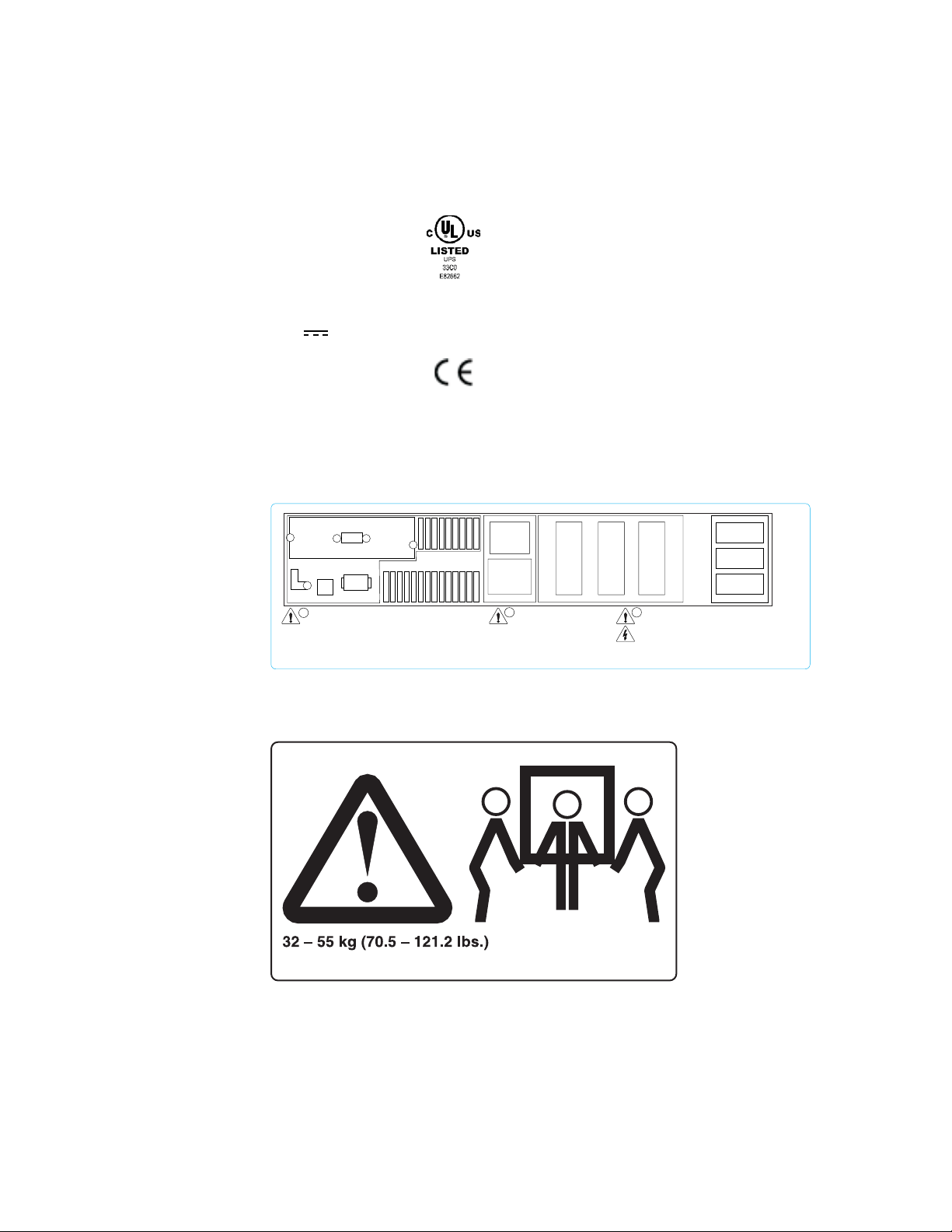
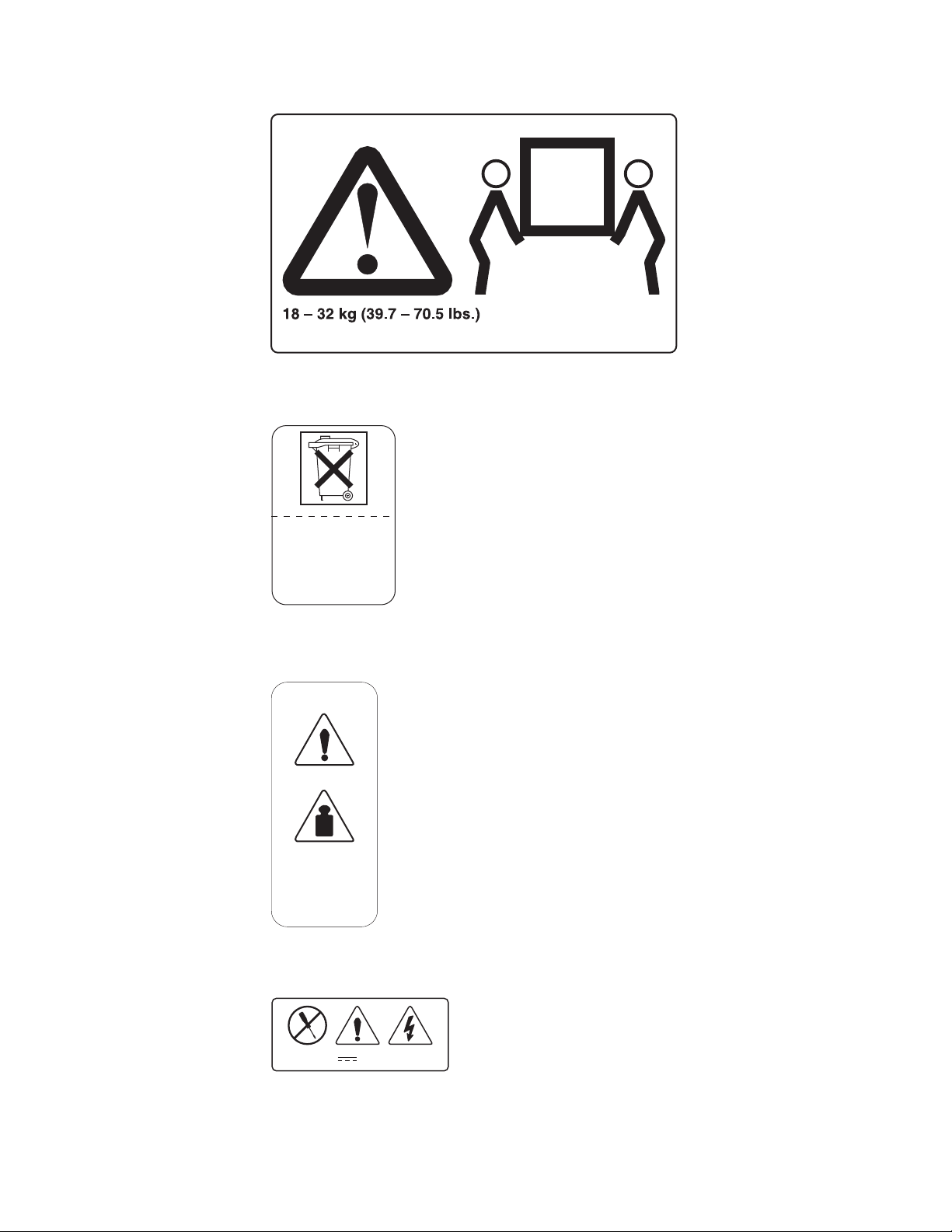
3. Three-man lift.
INPUT
INLET
LOAD
GROUP 1
16A MAX
2
REPO CONNECTOR: A
Use Class 2 Input Only
Utilisez Uniquement Une
Alimentation De Classe 2
BREAKER
1
BREAKER
10A MAX
10A MAX
LOAD GROUP 1
LOAD GROUP 2
This product is covered by one or more of the following U.S. Pat. Nos.
5177676, 6314007, 6330176, 6391489 & 6483730
10A MAX
LOAD GROUP 3
3
EXTENDED BATTERY CONNECTOR:
DO NOT DISCONNECT UNDER LOAD.
NE PAS DEBRANCER SOUS CHARGE.
2
BREAKER
3
4. Weight label.
About this guide xxiii
Page 26
5. IT compatible label.
THIS UNIT IS SUITABLE
FOR AN “IT-POWER
SYSTEM” CONNECTION
6. No user access label.
Checking the labels on the battery of the uninterruptible power supply
Ensure that you understand how to check the labels on the battery of the
uninterruptible power supply (UPS).
Checking the battery labels of the UPS 5115
|
|
|
Do not discard the UPS 5115 or the UPS 5115 batteries in the trash. The UPS may
contain sealed, lead-acid batteries, which must be recycled.
Pb
Checking the battery labels of the UPS 5125
v Two-man lift label.
xxiv IBM TotalStorage SAN Volume Controller: Installation Guide
Page 27
v Battery recycle label.
Pb
Unit contains lead-acid
batteries. Do not burn.
Recycle or discard the
batteries as instructed.
v Weight label.
21 kg
45 lbs
v Power ratings label.
Rating
:120V, 30A
v Battery faceplate label.
About this guide xxv
Page 28

CAUTION:
- For usein a controlledenvironment
- More thanone live circuit
Qualifiedservice personnel ONLY-
Pas på!
Til brug i et kontrolleret miljø
Mere end ét strømførende kredsløb
KUN uddannede serviceteknikere
РСПУПЧЗ:
ГйбчсЮуз уе елегчьменп ресйвЬллпн
Ресйууьфесббрь Энб злекфспцьсб кхклюмбфб
МПНП екрбйдехмЭнпфечнйкь рспущрйкь
CUIDADO:
Parautilização num ambiente controlado
Maisque um circuito em tensão
APENASpessoal qualificado de assistência
Note: You must remove the front panel to see the faceplate.
Environmental notices and statements
Ensure that you are familiar with the environmental notices and statements.
The following topics describe the environmental notices and statements that are
applicable to this product.
Product recycling
Ensure you are aware of the materials of the product that can be recycled.
Varoitus:
Käytön tulee tapahtuavalvotussa ympäristössä
Jännitteisiä virtapiirejäon enemmän kuin yksi
VAINvaltuutetulle huoltohenkilöstölle
OPREZ:
Za upotrebu u kontroliranom okruenju
Više od jednog ivog strujnog kruga
SAMO kvalificirano servisno osoblje
WAARSCHUWING:
Alleenvoor gebruik in een afgeschermde ruimte
Meerdan één circuit met spanning
UITSLUITENDbevoegd personeel
UPOZORNENIE:
Prepouitie v riadenom prostredí
Viacako jeden ivý obvod
LENkvalifikovaný servisný personál
ATTENTION:
Utilisationdans un environnement sous surveillance
Plusieurscircuits sous tension
Personnelde maintenance qualifié UNIQUEMENT
FIGYELMEZTETÉS:
Csak felügyelet alatt álló környezetben használható
Egynél több feszültség alatt álló áramkör
CSAK kiképzett javító szakember
ADVARSEL:
Til bruk i et kontrollert miljø
Mer enn én strømførende krets
KUN kvalifisert servicepersonale
VARNING:
Användendast under kontrollerade förhållanden
Fleraströmförande kretsar
Endastför kvalificerad servicepersonal
Achtung:
Nur in einer kontrollierten Umgebung
Mehrere unter Spannungstehende Stromkreise
Ausführung nur durch Fachpersonal
AVVERTENZA:
Perl’utilizzo in un ambiente controllato
Piùdiuncircuito
SOLOpersonale qualificato dell’assistenza tecnica
ZAGRO¯ENIE:
Dou¿ywania w œrodowisku kontrolowanym.
Wiêcejni¿ jeden obwód pod napiêciem.
WY£¥CZNIEdla wykwalifikowanych pracowników serwisu.
This unit contains recyclable materials. These materials should be recycled where
processing sites are available and according to local regulations. In some areas,
IBM provides a product take-back program that ensures proper handling of the
product. Contact your IBM representative for more information.
Product disposal
Ensure that you are aware of the proper disposal for certain parts on the SAN
Volume Controller.
This unit might contain batteries. Remove and discard these batteries, or recycle
them, according to local regulations.
Battery disposal
Ensure that you understand the precautions you need to take when disposing of
batteries.
CAUTION:
A lithium battery can cause fire, explosion, or a severe burn. Do not recharge,
disassemble, heat above 100°C (212°F), solder directly to the cell, incinerate,
or expose cell contents to water. Keep away from children. Replace only with
the part number specified for your system. Use of another battery might
present a risk of fire or explosion. The battery connector is polarized; do not
attempt to reverse the polarity. Dispose of the battery according to local
regulations. (51)
Handling static-sensitive devices
Ensure that you understand how to handle devices that are sensitive to static
electricity.
xxvi IBM TotalStorage SAN Volume Controller: Installation Guide
Page 29

Attention: Static electricity can damage electronic devices and your system. To
avoid damage, keep static-sensitive devices in their static protective bags until you
are ready to install them.
To reduce the possibility of electrostatic discharge, observe the following
precautions:
v Limit your movement. Movement can cause static electricity to build up around
you.
v Handle the device carefully, holding it by its edges or its frame.
v Do not touch solder joints, pins, or exposed printed circuitry.
v Do not leave the device where others can handle and possibly damage the
device.
v While the device is still in its anti-static bag, touch it to an unpainted metal part of
the system unit for at least 2 seconds. (This action removes static electricity from
the package and from your body.)
v Remove the device from its package and install it directly into your SAN Volume
Controller, without putting it down. If it is necessary to put the device down, place
it onto its static-protective bag. (If your device is an adapter, place it component
side up.) Do not place the device onto the cover of the SAN Volume Controller or
onto a metal table.
v Take additional care when you handle devices during cold weather because
heating reduces indoor humidity and increases static electricity.
About this guide xxvii
Page 30

xxviii IBM TotalStorage SAN Volume Controller: Installation Guide
Page 31

Chapter 1. Overview of the SAN Volume Controller
This chapter describes the SAN Volume Controller and all of its components.
Related concepts
“SAN Volume Controller”
SAN Volume Controller is a SAN appliance that attaches open-systems
The
storage devices to supported open-systems hosts.
Related reference
“Controls and indicators for the SAN Volume Controller” on page 5
Controls
Controller.
“SAN Volume Controller rear panel indicators” on page 7
The
front and back panel assembly.
“SAN Volume Controller hardware” on page 9
The
graphic below.
“SAN Volume Controller connectors” on page 11
The
“Preparing your SAN Volume Controller environment” on page 12
Before
and indicators are located on the front panel of the SAN Volume
controls and indicators for the SAN Volume Controller are contained on the
SAN Volume Controller hardware is identified in the chart and shown in the
external connectors for the SAN Volume Controller can be located easily.
installing the SAN Volume Controller, prepare the physical environment.
SAN Volume Controller
The SAN Volume Controller is a SAN appliance that attaches open-systems storage
devices to supported open-systems hosts.
The IBM TotalStorage SAN Volume Controller provides symmetric virtualization by
creating a pool of managed disks from the attached storage subsystems, which are
then mapped to a set of virtual disks for use by attached host computer systems.
System administrators can view and access a common pool of storage on the SAN,
which enables them to use storage resources more efficiently and provides a
common base for advanced functions.
The SAN Volume Controller is analogous to a logical volume manager (LVM) on a
SAN. It performs the following functions for the SAN storage that it is controlling:
v Creates a single pool of storage
|
v Logical unit virtualization
v Manages logical volumes
v Provides advanced functions for the SAN, such as:
– Large scalable cache
– Copy services
Space management
–
®
- FlashCopy
(point-in-time copy)
- Metro Mirror (synchronous copy)
- Data migration
- Mapping that is based on desired performance characteristics
- Quality of service metering
© Copyright IBM Corp. 2003, 2005 1
Page 32

A node is a single storage engine. Figure 4 provides an illustration of a node. The
storage engines are always installed in pairs with one to four pairs of nodes
constituting a cluster. Each node in a pair is configured to back up the other. Each
pair of nodes is known as an I/O group. All I/O operations that are managed by the
nodes in an I/O group are cached on both nodes for resilience. Each virtual volume
is defined to an I/O group. To avoid any single point of failure, the nodes of an I/O
group are protected by independent uninterruptible power supply (UPS) 5115 or
uninterruptible power supply (UPS) 5125 units.
Figure 4. A SAN Volume Controller node
The SAN Volume Controller I/O groups recognize the storage presented to the SAN
by the backend controllers as a number of disks known as managed disks. The
application servers do not recognize these managed disks. Instead they see a
number of logical disks, known as virtual disks, that are presented to the SAN by
the SAN Volume Controller. Each node must be in only one I/O group and provide
access to the virtual disks in the I/O group.
The SAN Volume Controller helps to provide continuous operations and can also
optimize the data path to ensure performance levels are maintained. Ensure that
you use IBM TotalStorage Multiple Device Manager performance manager to
analyze the performance statistics. See IBM TotalStorage Multiple Device Manager
Configuration and Installation Guide and IBM TotalStorage Multiple Device Manager
CLI Guide for more information.
The fabric contains two distinct zones: a host zone and a disk zone. In the host
zone, the host systems can identify and address the nodes. Yo u can have more
than one host zone. Generally, you will create one host zone per operating system
type. In the disk zone, the nodes can identify the disk drives. Host systems cannot
operate on the disk drives directly; all data transfer occurs through the nodes.
Figure 5 on page 3 shows that several host systems can be connected to a SAN
fabric. A cluster of SAN Volume Controller nodes is connected to the same fabric
and presents virtual disks to the host systems. Yo u create these virtual disks from
units of space within a managed disk group. A managed disk group is a collection
of managed disks presented by the back-end RAID controllers, providing a storage
2 IBM TotalStorage SAN Volume Controller: Installation Guide
Page 33

pool. Yo u choose how each group is made up, and you can combine managed
disks from different manufacturers’ controllers in the same managed disk group if
required.
Note: Some operating systems cannot tolerate other operating systems in the
same zone.
Host zone
Host Host Host Host
SAN Volume
Controller
SAN Volume
Controller
.
.
Fibre Channel
Fabric
.
SAN Volume
Controller
RAID RAID RAID RAID
...
Disk zone
Figure 5. Example of a SAN Volume Controller in a fabric
You can remove one node in each I/O group from a cluster when hardware service
or maintenance is required. After you remove the node, you can replace the field
replaceable units (FRUs) in the node. All disk drive communication and
communication between nodes is performed through the SAN. All SAN Volume
Controller configuration and service commands are sent to the cluster through an
Ethernet network.
Each node contains its own vital product data (VPD). Each cluster contains VPD
that is common to all the nodes on the cluster, and any system connected to the
Ethernet network can access this VPD.
Cluster configuration information is stored on every node that is in the cluster to
allow concurrent replacement of FRUs. An example of this information might be
information that is displayed on the menu screen of the SAN Volume Controller.
When a new FRU is installed and when the node is added back into the cluster,
configuration information that is required by that node is read from other nodes in
the cluster.
SAN Volume Controller operating environment
v Minimum of one pair of SAN Volume Controller nodes
v Minimum of two uninterruptible power supplies
Chapter 1. Overview of the SAN Volume Controller 3
Page 34

v One master console is required per SAN installation for configuration
Features
of a SAN Volume Controller node
v 19-inch rack mounted enclosure
v 4 fibre channel ports
v 2 fibre channel adapters
v 4 GB cache memory
Supported
hosts
For a list of supported operating systems, see the IBM TotalStorage SAN Volume
Controller Web site at:
http://www-1.ibm.com/servers/storage/support/virtual/2145.html
Multipathing software
v IBM Subsystem Device Driver (SDD)
v Redundant Dual Active Controller (RDAC)
|
|
|
Directly-attached hosts that share a back-end storage controller with a SAN
Note:
Volume Controller can run multipath drivers SDD and RDAC simultaneously.
Other multipath drivers running with SDD are not supported.
Check the following Web site for the latest support and coexistence information:
http://www-1.ibm.com/servers/storage/support/virtual/2145.html
User interfaces
The SAN Volume Controller provides the following user interfaces:
v IBM TotalStorage SAN Volume Controller Console, a Web-accessible graphical
user interface (GUI) that supports flexible and rapid access to storage
management information
v A command-line interface (CLI) using Secure Shell (SSH)
Application
programming interfaces
The SAN Volume Controller provides the following application programming
interface:
v IBM TotalStorage Common Information Model (CIM) Agent for the SAN Volume
Controller, which supports the Storage Management Initiative Specification of the
Storage Network Industry Association.
Related reference
“Controls and indicators for the SAN Volume Controller” on page 5
Controls and indicators are located on the front panel of the SAN Volume
Controller.
“SAN Volume Controller rear panel indicators” on page 7
The controls and indicators for the SAN Volume Controller are contained on the
front and back panel assembly.
“SAN Volume Controller hardware” on page 9
The SAN Volume Controller hardware is identified in the chart and shown in the
graphic below.
4 IBM TotalStorage SAN Volume Controller: Installation Guide
Page 35

“SAN Volume Controller connectors” on page 11
The external connectors for the SAN Volume Controller can be located easily.
“Preparing your SAN Volume Controller environment” on page 12
Before installing the SAN Volume Controller, prepare the physical environment.
Controls and indicators for the SAN Volume Controller
Controls and indicators are located on the front panel of the SAN Volume Controller.
All the controls for the SAN Volume Controller are located on the front panel.
3
1
2145
1
3
5
6
7
Related reference
“Power button”
The
2
Power button
2
Power LED
Check LED
4
Navigation buttons
Select button
Front panel display
Label
power button switches the main power to the SAN Volume Controller on or
4
off.
“Power LED” on page 6
green power LED indicates the power status of the SAN Volume Controller:
The
“Check LED” on page 6
This is an amber LED used to indicate critical failures on the service controller.
“Navigation buttons” on page 6
Use the navigation buttons to move through menus.
“Select button” on page 6
Use the select button to select an item from a menu.
“Front panel display” on page 7
The front panel display shows service, configuration, and navigation information.
“Node identification label” on page 7
The node identification label on the front panel displays a six-digit node
identification number.
5
6
7
Power button
The power button switches the main power to the SAN Volume Controller on or off.
To turn on the power, press and release the power button.
To turn off the power, press and release the power button.
Chapter 1. Overview of the SAN Volume Controller 5
Page 36

|
|
|
|
|
|
Power LED
Attention: If a SAN Volume Controller is powered off for more than five minutes
and it is the only SAN Volume Controller that is connected to an uninterruptible
power supply (UPS) 5125, the UPS 5125 also powers off. To power on the SAN
Volume Controller, you must first power on the UPS 5125 to which it is connected.
The UPS 5115 will not power off when the SAN Volume Controller is shut
Note:
down from the power button.
The green power LED indicates the power status of the SAN Volume Controller:
The properties of the green power LED are as follows:
Off
v One or more output voltages from the power supply are not present.
On
v All the output voltages from the power supply are present.
Blinking
v The service controller, which provides the graphics and text for the front panel
display, is in standby mode. (The rate of blinking is 0.5 seconds on, 0.5 seconds
off.)
Check LED
This is an amber LED used to indicate critical failures on the service controller.
If the check LED is off and the power LED is on, the service controller is working
correctly.
If the check LED is on, a critical service controller failure has been detected.
The check LED is also on while the service controller code is being reprogrammed.
For example, when the SAN Volume Controller cluster code is being upgraded, the
check LED will be on. It is normal for the check LED to be on at this time.
Navigation buttons
Use the navigation buttons to move through menus.
There are four navigational buttons that you can use to move throughout a menu:
up, down, right and left.
Each button corresponds to the direction that you can move in a menu. For
example, to move right in a menu, press the navigation button that is located on the
right side. If you want to move down in a menu, press the navigation button that is
located on the bottom.
Select button
Use the select button to select an item from a menu.
The select button is located on the front panel of the SAN Volume Controller, near
the navigation buttons.
6 IBM TotalStorage SAN Volume Controller: Installation Guide
Page 37

Front panel display
The front panel display shows service, configuration, and navigation information.
Information on the front panel display is available in several national languages.
The display can show both alphanumeric information and graphical information
(progress bars).
The front panel displays configuration and service information about the SAN
Volume Controller and the SAN Volume Controller cluster including the following
items:
v Hardware boot
v Node rescue request
v Boot progress
v Boot failed
v Powering off
v Restarting
v Shutting down
v Power failure
v Error codes
Node identification label
The node identification label on the front panel displays a six-digit node
identification number.
The node identification label is the same as the six-digit number used in the
addnode command. It is readable by system software and is used by configuration
and service software as a node identifier. The node identifier can also be displayed
on the front panel display when node is selected from the menu.
If the front panel is replaced, the configuration and service software displays the
number that is printed on the front of the replacement panel. Future error reports
will also contain the new number. No cluster reconfiguration is necessary when the
front panel is replaced.
The node also contains a SAN Volume Controller product serial number that is
imbedded on the system board hardware. This number is used for warranty and
service entitlement checking and is included in the data sent with error reports. It is
essential that this number is not changed during the life of the product. If the
system board is replaced, you must follow the system board replacement
instructions carefully and rewrite the serial number on the system board.
SAN Volume Controller rear panel indicators
The controls and indicators for the SAN Volume Controller are contained on the
front and back panel assembly.
The following figure shows the location of the controls and indicators:
Chapter 1. Overview of the SAN Volume Controller 7
Page 38

4
3
5
2
1
1
System board power LED
2
Related reference
System board fault LED
3
Monitor LED (not used)
4
Lower Ethernet connection LED
5
Upper Ethernet connection LED
“System board power LED”
The system board power LED indicates the power supply status that is detected
by the system board.
“System board fault LED” on page 9
The amber system board fault LED indicates that the system board has
detected a critical failure.
“Monitor LED” on page 9
The green monitor LED is not used on the SAN Volume Controller.
“Lower Ethernet connection LED” on page 9
lower Ethernet connection LED indicates the operational status of Ethernet
The
port 1. This LED is illuminated when a good Ethernet connection exists between
the SAN Volume Controller and the Ethernet network.
“Upper Ethernet connection LED” on page 9
The upper Ethernet connection LED indicates the operational status of Ethernet
port 2. Ethernet port 2 is not used on the SAN Volume Controller except during
Ethernet problem determination.
System board power LED
The system board power LED indicates the power supply status that is detected by
the system board.
|
|
|
|
|
|
8 IBM TotalStorage SAN Volume Controller: Installation Guide
Attention: If a SAN Volume Controller is powered off for more than five minutes
and it is the only SAN Volume Controller connected to an uninterruptible power
supply (UPS) 5125, the UPS 5125 will also power off. To power on the SAN Volume
Controller, you must first power on its UPS 5125 to which it is connected.
The UPS 5115 will not power off when the SAN Volume Controller is shut
Note:
down from the power button.
Page 39

System board fault LED
The amber system board fault LED indicates that the system board has detected a
critical failure.
You can view the system board fault LED in “SAN Volume Controller rear panel
indicators.”
Monitor LED
The green monitor LED is not used on the SAN Volume Controller.
You can view the monitor LED in “SAN Volume Controller rear panel indicators.”
Lower Ethernet connection LED
The lower Ethernet connection LED indicates the operational status of Ethernet port
1. This LED is illuminated when a good Ethernet connection exists between the
SAN Volume Controller and the Ethernet network.
You can view the lower Ethernet connection LED in “SAN Volume Controller rear
panel indicators.”
Upper Ethernet connection LED
The upper Ethernet connection LED indicates the operational status of Ethernet port
2. Ethernet port 2 is not used on the SAN Volume Controller except during Ethernet
problem determination.
You can view the upper Ethernet connection LED in “SAN Volume Controller rear
panel indicators.”
SAN Volume Controller hardware
The SAN Volume Controller hardware is identified in the chart and shown in the
graphic below.
The following figure displays a breakout view for the parts to the SAN Volume
Controller. Use the reference keys below the figure to match the reference keys in
the example.
Chapter 1. Overview of the SAN Volume Controller 9
Page 40

1
16
15
14
13
12
(x4)
11
10
9
2
3
4
5
8
(x4)
1
To p cover
2
Power supply connector
3
Fan with baffle
4
Power supply assembly
5
Hard disk drive
6
Front panel
10 IBM TotalStorage SAN Volume Controller: Installation Guide
6
7
Page 41

7
Service controller card
8
Fan assembly (4)
9
Air baffle
10
Microprocessor heat sink retention module
11
System board
12
DIMM modules (4)
13
Microprocessor Voltage Regulator
14
Microprocessor
15
Microprocessor heat sink
16
Fibre-channel adapters (2)
SAN Volume Controller connectors
The external connectors for the SAN Volume Controller can be located easily.
21
3
4
8
7
6
5
Use the reference keys below to cross reference the reference keys in the example
above:
1
The
Power connector indicator
2
Fibre-channel port 3
3
Fibre-channel port 4
4
Ethernet port 2 (not used on the SAN Volume Controller)
5
Ethernet port 1
6
Serial connector
7
Fibre-channel port 2
8
Fibre-channel port 1
following figure shows the type of connector located on the power supply
assembly. The connector allows you to connect the SAN Volume Controller to the
power source from the uninterruptible power supply.
Chapter 1. Overview of the SAN Volume Controller 11
Page 42

Neutral
Ground
Live
Preparing your SAN Volume Controller environment
Before installing the SAN Volume Controller, prepare the physical environment.
Dimensions and weight
The following tables list the physical dimensions and weight of the SAN Volume
Controller, as well as other environmental requirements that you must consider
before you install your SAN Volume Controller:
Height Width Depth Maximum Weight
43 mm
(1.7 in.)
440 mm
(17.3 in.)
660 mm
(26 in.)
12.7 kg
(28 lb.)
Additional space requirements
Location
Left and right sides 50 mm
Back minimum:
Additional Space
Required Reason
Cooling air flow
(2 in.)
Cable exit
100 mm (4 in.)
AC input-voltage requirements
Power Supply
Assembly Type Voltage Frequency
200 to 240 V 88 to 264 V ac 50 to 60 Hz
Environment
Relative
Environment Temperature Altitude
Operating in
Lower Altitudes
Operating in
Higher Altitudes
Powered Off 10°C to 43°C
10°C to 35°C
(50°F to 95°F)
10°C to 32°C
(50°F to 88°F)
0 to 914 m
(0 to 2998 ft.)
914 to 2133 m
(2998 to
6988 ft.)
– 8% to 80%
(50°F to 110°F)
Humidity
8% to 80%
noncondensing
8% to 80%
noncondensing
noncondensing
Maximum
Wet Bulb
Temperature
23°C
(74°F )
23°C
(74°F )
27°C
(81°F )
12 IBM TotalStorage SAN Volume Controller: Installation Guide
Page 43

Maximum
Environment Temperature Altitude
Storing 1°C to 60°C
(34°F to 140°F)
Shipping -20°C to 60°C
(-4°F to 140°F)
0 to 2133 m
(0 to 6988 ft.)
0 to 10668 m
(0 to 34991 ft.)
Relative
Humidity
5% to 80%
noncondensing
5% to 100%
condensing,
Wet Bulb
Temperature
29°C
(84°F)
29°C
(84°F)
but no
precipitation
Heat output (maximum)
350 watts (1195 Btu per hour)
Related reference
“Preparing your uninterruptible power supply environment” on page 30
Ensure
that your physical site meets the installation requirements for the
uninterruptible power supply (UPS).
Chapter 1. Overview of the SAN Volume Controller 13
Page 44

14 IBM TotalStorage SAN Volume Controller: Installation Guide
Page 45

Chapter 2. Overview of the uninterruptible power supply
This chapter describes the uninterruptible power supply and all of its components.
Related reference
“Controls and indicators for the uninterruptible power supply 5115” on page 19
All controls for the uninterruptible power supply 5115 are located on the front
panel assembly.
“Controls and indicators for the uninterruptible power supply 5125” on page 22
All controls for the uninterruptible power supply 5125 are located on the front
panel assembly.
“Hardware for the uninterruptible power supply 5115” on page 25
Diagrams of the hardware for the uninterruptible power supply (UPS) 5115 are
shown below:
“Hardware for the uninterruptible power supply 5125” on page 26
Diagrams of the hardware for the uninterruptible power supply (UPS) 5125 are
shown below:
“Preparing your uninterruptible power supply environment” on page 30
Ensure
uninterruptible power supply (UPS).
that your physical site meets the installation requirements for the
Uninterruptible power supply overview
The uninterruptible power supply (UPS) provides the SAN Volume Controller with a
secondary power source to be used if you lose power from your primary power
|
|
|
source due to power failures, power sags, power surges, or line noise. Two types of
UPS units can be used with the SAN Volume Controller: the UPS 5115 and the
UPS 5125.
If a power outage occurs, the UPS maintains power long enough to save any
configuration and cache data contained in the dynamic random access memory
(DRAM). The data is saved to the SAN Volume Controller internal disk. Figure 6 on
page 16 and Figure 7 on page 16 provide illustrations of the two types of UPS
units.
© Copyright IBM Corp. 2003, 2005 15
Page 46

Figure 6. Uninterruptible power supply 5125
Figure 7. Uninterruptible power supply 5115
Note: The SAN Volume Controller UPS is an integral part of the SAN Volume
Controller solution. It maintains continuous SAN Volume Controller specific
communications with its attached SAN Volume Controller nodes. The SAN
Volume Controller cannot operate without the UPS. The SAN Volume
Controller UPS must be used in accordance with documented guidelines and
procedures and must not power any equipment other than SAN Volume
Controller nodes.
svc00001
To provide full redundancy and concurrent maintenance, the SAN Volume Controller
must be installed in pairs. Each SAN Volume Controller of a pair must be connected
to a different UPS. Each UPS 5125 can support up to two SAN Volume Controller
|
nodes. The UPS 5115 can support one SAN Volume Controller node. It is also
16 IBM TotalStorage SAN Volume Controller: Installation Guide
Page 47

recommended that you connect the two UPS units for the pair to different
independent electrical power sources. This reduces the chance of an input power
failure at both UPS units.
The UPS must be in the same rack as the nodes. Ensure that you are following the
UPS guidelines that are provided in Table 1.
|
|
|||||
|||
|||
|||
|||
|
Table 1. Uninterruptible power supply support guidelines
Number of uninterruptible
Number of nodes
2 2 2
4 2 4
6 4 6
8 4 8
power supply 5125 units
Number of uninterruptible
power supply 5115 units
Attention:
1. Do not connect the uninterruptible power supplies to an input power
source that does not conform to standards.
2. Each UPS pair must power only one SAN Volume Controller cluster.
UPS includes power (line) cords that connect the UPS to either a rack power
Each
distribution unit (PDU), if one exists, or to an external power source. Each UPS
power input requires the protection of a UL-approved (or equivalent) 250 volt, 15
amp circuit breaker.
The UPS is connected to the SAN Volume Controllers with a power cable and a
signal cable. To avoid the possibility of power and signal cables being connected to
different UPS units, these cables are wrapped together and supplied as a single
field replaceable unit. The signal cables enable the SAN Volume Controllers to read
status and identification information from the UPS.
Each SAN Volume Controller monitors the operational state of the UPS to which it
is attached. If the UPS reports a loss of input power, the SAN Volume Controller
stops all I/O operations and dumps the contents of its DRAM to the internal disk
drive. When input power to the UPS is restored, the SAN Volume Controllers restart
and restore the original contents of the DRAM from the data saved on the disk
drive.
A SAN Volume Controller is not fully operational until the UPS battery charge state
indicates that it has sufficient capacity to power the SAN Volume Controller long
enough to permit it to save all its memory to the disk drive in the event of a power
loss. The UPS has sufficient capacity to save all the data on the SAN Volume
Controller at least twice. For a fully-charged UPS, even after battery capacity has
been used to power the SAN Volume Controllers while they save DRAM data,
sufficient battery capacity remains to let the SAN Volume Controllers become fully
operational as soon as input power is restored.
Note: Under normal circumstances, if input power is disconnected from the UPS,
the SAN Volume Controller connected to that UPS performs a power down
sequence. This operation, which saves the configuration and cache data to
an internal disk in the SAN Volume Controller, typically takes about three
minutes, at which time power is removed from the output of the UPS. In the
event of a delay in the completion of the power down sequence, the UPS
Chapter 2. Overview of the uninterruptible power supply 17
Page 48

output power is removed five minutes after the power was disconnected to
the UPS. Because this operation is controlled by the SAN Volume Controller,
a UPS that is not connected to an active SAN Volume Controller will not shut
off within the five-minute required period. In the case of an emergency, you
must manually shut down the UPS by pushing the UPS 5125 power off
|
button, or the UPS 5115 on/off button.
|
|
|
Attention: Data integrity could be compromised by pushing the UPS 5125 power
off button or the UPS 5115 on/off button. Never shut down a UPS without first
shutting down the SAN Volume Controller nodes that it supports.
It is very important that the two nodes in the I/O group are connected to different
uninterruptible power supplies. This configuration ensures that cache and cluster
state information is protected in the event of a failure of the UPS or mainline power
source.
When nodes are added to the cluster, you must specify the I/O group that they will
join. The configuration interfaces also checks the UPS units and ensures that the
two nodes in the I/O group are not connected to the same UPS units.
Figure 8 shows a cluster of four nodes, with two I/O groups and two UPS 5125
units.
I/O group 1 I/O group 2
Node 1
UPS 1
Node 3
Vdisks
Node 2
UPS 2
Node 4
Vdisks
Figure 8. I/O groups and uninterruptible power supply 5125 relationship
Related reference
“Controls and indicators for the uninterruptible power supply 5115” on page 19
All controls for the uninterruptible power supply 5115 are located on the front
panel assembly.
“Controls and indicators for the uninterruptible power supply 5125” on page 22
All controls for the uninterruptible power supply 5125 are located on the front
panel assembly.
“Hardware for the uninterruptible power supply 5115” on page 25
Diagrams of the hardware for the uninterruptible power supply (UPS) 5115 are
shown below:
“Hardware for the uninterruptible power supply 5125” on page 26
Diagrams of the hardware for the uninterruptible power supply (UPS) 5125 are
shown below:
18 IBM TotalStorage SAN Volume Controller: Installation Guide
Page 49

“Preparing your uninterruptible power supply environment” on page 30
Ensure that your physical site meets the installation requirements for the
uninterruptible power supply (UPS).
Controls and indicators for the uninterruptible power supply 5115
|
|
|
|
All controls for the uninterruptible power supply 5115 are located on the front panel
assembly.
1
LOAD 1LOAD 2
+-+ -
2
3
5
8
1
|
|
|
|
|
|
|
|
|
|
Related reference
|
|
|
|
|
|
|
|
|
|
|
|
|
|
Power-on indicator
2
On/off button
3
Test and alarm reset button
4
Overload indicator
5
On-battery indicator
6
Service indicator
7
Load segment 1 indicator
8
Load segment 2 indicator
“Power-on indicator” on page 20
The power-on indicator shows when the uninterruptible power supply (UPS)
5115 is functioning.
“On/off button” on page 20
The on/off button turns the power on or off to the uninterruptible power supply
(UPS) 5115.
“Test and alarm reset button” on page 20
Use the test and alarm reset button to start the self-test.
“Overload indicator” on page 21
The overload indicator beeps when the capacity of the uninterruptible power
supply (UPS) 5115 is exceeded.
“On-battery indicator” on page 21
The on-battery indicator glows yellow when the uninterruptible power supply
(UPS) 5115 is powered by the battery. This indicates that the main power source
has failed.
6
7
4
1yyzvm
Chapter 2. Overview of the uninterruptible power supply 19
Page 50

|
|
|
|
|
|
|
|
|
Power-on indicator
|
|
|
|
|
|
|
|
On/off button
|
|
|
“Service indicator” on page 21
If the service indicator on the uninterruptible power supply (UPS) 5115 is
flashing red, maintenance is required.
“Load segment 1 indicator” on page 21
The load segment 1 indicator on the uninterruptible power supply (UPS) 5115 is
lit (yellow) when power is available to load segment 1.
“Load segment 2 indicator” on page 21
The load segment 2 indicator on the uninterruptible power supply (UPS) 5115 is
lit (green) when power is available to load segment 2.
The power-on indicator shows when the uninterruptible power supply (UPS) 5115 is
functioning.
When the power-on indicator is a steady green, the UPS 5115 is active.
Related reference
“Controls and indicators for the uninterruptible power supply 5115” on page 19
All controls for the uninterruptible power supply 5115 are located on the front
panel assembly.
The on/off button turns the power on or off to the uninterruptible power supply
(UPS) 5115.
|
|
|
|
|
|
|
|
|
|
|
|
Test and alarm reset button
|
|
|
|
|
|
|
|
|
|
Turning on the uninterruptible power supply 5115
After connecting the UPS 5115 to the outlet, it will be in “standby” mode until you
turn it on. Press and hold the on/off button until a beep sounds (approximately two
seconds). This indicates that the UPS 5115 is powered on and a self-test is
initiated. The UPS 5115 then reverts to “normal” mode.
Turning off the uninterruptible power supply 5115
Press and hold the on/off button for two seconds. This will place the UPS 5115 in
“standby” mode. You must then unplug the UPS 5115 to power-off the unit.
Related reference
“Controls and indicators for the uninterruptible power supply 5115” on page 19
All controls for the uninterruptible power supply 5115 are located on the front
panel assembly.
Use the test and alarm reset button to start the self-test.
To start the self-test, press and hold the test and alarm reset button for three
seconds. This button also resets the alarm.
This button is applicable to both the uninterruptible power supply (UPS) 5115
Note:
and the UPS 5125.
Related reference
“Controls and indicators for the uninterruptible power supply 5115” on page 19
All controls for the uninterruptible power supply 5115 are located on the front
panel assembly.
20 IBM TotalStorage SAN Volume Controller: Installation Guide
Page 51

Overload indicator
|
|
|
The overload indicator beeps when the capacity of the uninterruptible power supply
(UPS) 5115 is exceeded.
|
|
If the overload indicator is on, go to MAP 5200: Uninterruptible Power Supply 5115
to resolve the problem.
|
|
|
|
On-battery indicator
|
|
|
|
|
|
The on-battery indicator glows yellow when the uninterruptible power supply (UPS)
5115 is powered by the battery. This indicates that the main power source has
failed.
If the on-battery indicator is on, go to MAP 5200: Uninterruptible Power Supply 5115
to resolve the problem.
|
|
|
|
Service indicator
|
|
|
If the service indicator on the uninterruptible power supply (UPS) 5115 is flashing
red, maintenance is required.
Related reference
“Controls and indicators for the uninterruptible power supply 5115” on page 19
All controls for the uninterruptible power supply 5115 are located on the front
panel assembly.
Related reference
“Controls and indicators for the uninterruptible power supply 5115” on page 19
All controls for the uninterruptible power supply 5115 are located on the front
panel assembly.
|
|
|
|
|
|
Load segment 1 indicator
|
|
|
|
|
|
|
|
|
|
Load segment 2 indicator
|
|
|
If the service indicator is on, go to MAP 5200: Uninterruptible Power Supply 5115 to
resolve the problem.
Related reference
“Controls and indicators for the uninterruptible power supply 5115” on page 19
All controls for the uninterruptible power supply 5115 are located on the front
panel assembly.
The load segment 1 indicator on the uninterruptible power supply (UPS) 5115 is lit
(yellow) when power is available to load segment 1.
Note: Load segment 1 is unused by the SAN Volume Controller. When the UPS
5115 is configured by the SAN Volume Controller, this load segment is
disabled. During normal operation, the load segment 1 indicator will be off.
Related reference
“Controls and indicators for the uninterruptible power supply 5115” on page 19
All controls for the uninterruptible power supply 5115 are located on the front
panel assembly.
The load segment 2 indicator on the uninterruptible power supply (UPS) 5115 is lit
(green) when power is available to load segment 2.
Chapter 2. Overview of the uninterruptible power supply 21
Page 52

|
|
|
|
|
|
|
|
When the load segment 2 indicator is green, the UPS 5115 is running normally and
power is available to this segment.
See “Hardware for the uninterruptible power supply 5115” for the location of the
power outlets for this segment.
Related reference
“Controls and indicators for the uninterruptible power supply 5115” on page 19
All controls for the uninterruptible power supply 5115 are located on the front
panel assembly.
Controls and indicators for the uninterruptible power supply 5125
All controls for the uninterruptible power supply 5125 are located on the front panel
assembly.
+-+ - +-+ -
1
100%
25%
2
3
4
5
1
Related reference
Mode indicator
2
On button
3
Off button
4
Test and alarm reset button
5
Load-level indicators
6
Site wiring fault indicators
7
Battery service indicator
8
Battery mode indicator
9
General alarm indicator
“Mode indicator” on page 23
6
789
The mode indicator provides status information on the uninterruptible power
supply (UPS) 5125.
“On button” on page 23
The on button turns on the main power to the uninterruptible power supply
(UPS) 5125.
“Off button” on page 24
The off button turns off the main power to the uninterruptible power supply
(UPS) 5125.
22 IBM TotalStorage SAN Volume Controller: Installation Guide
Page 53

Mode indicator
“Test and alarm reset button” on page 20
Use the test and alarm reset button to start the self-test.
“Load-level indicators” on page 24
The load-level indicators show the percentage of uninterruptible power supply
(UPS) 5125 capacity that the SAN Volume Controller is using.
“Site wiring fault indicators” on page 24
The site wiring fault indicator on the uninterruptible power supply (UPS) 5125
shows that either a ground wire connection does not exist or the live and neutral
wires are reversed in the input power connection.
“Battery service indicator” on page 24
The battery service indicator shows that the charge in the battery has become
low while the uninterruptible power supply (UPS) 5125 is in battery mode.
“Battery mode indicator” on page 24
The battery mode indicator shows that the uninterruptible power supply (UPS)
5125 is operating on batteries.
“General alarm indicator” on page 24
The general alarm indicator on the uninterruptible power supply (UPS) 5125
turns on when a power or temperature problem occurs.
The mode indicator provides status information on the uninterruptible power supply
(UPS) 5125.
The mode indicator is located on the front panel of the UPS 5125.
When the mode indicator is steady green, the UPS 5125 is in normal mode. The
UPS 5125 checks and charges its battery as necessary.
When the mode indicator is flashing green, the UPS 5125 is in standby mode.
Standby mode means that the UPS 5125 is turned off, but is still connected to the
main power source. No power is available from the UPS 5125 output sockets but
the UPS 5125 monitors and charges its battery as necessary.
When the mode indicator is steady red, the UPS 5125 is in bypass mode because
of one of the following conditions:
v The UPS 5125 has overheated
v The UPS 5125 has an overload condition of 103% through 110% for 30 seconds
v The UPS 5125 detects a fault in the battery or in the UPS 5125 electronics
assembly
the mode indicator is flashing red and the alarm is sounding, the voltage
When
range setting might not be correct. When a SAN Volume Controller is connected to
the UPS 5125, the SAN Volume Controller automatically adjusts the voltage range
setting. Take no action for this alarm condition unless it persists for more than five
minutes after a SAN Volume Controller has been connected to this UPS 5125 and
powered on.
On button
The on button turns on the main power to the uninterruptible power supply (UPS)
5125.
Chapter 2. Overview of the uninterruptible power supply 23
Page 54

To turn on the power, press and hold the on button until you hear a beep
(approximately one second). The mode indicator stops flashing, and the load-level
indicators display the percentage of load that is being applied to the UPS 5125.
Off button
The off button turns off the main power to the uninterruptible power supply (UPS)
5125.
Attention: Never use the off button unless you are specifically directed to in the
instructions that are given in the publications for the SAN Volume Controller. If you
press it at any other time, you might lose data in the cluster if the other UPS 5125
fails.
To turn off the power, press and hold the off button until the long beep stops
(approximately five seconds). The mode indicator starts to flash, and the UPS 5125
remains in standby mode until you disconnect the UPS 5125 from the main power
outlet.
Load-level indicators
The load-level indicators show the percentage of uninterruptible power supply
(UPS) 5125 capacity that the SAN Volume Controller is using.
When all the indicators are lit, the power requirements of the SAN Volume
Controller have exceeded the capacity of the UPS 5125.
Site wiring fault indicators
The site wiring fault indicator on the uninterruptible power supply (UPS) 5125 shows
that either a ground wire connection does not exist or the live and neutral wires are
reversed in the input power connection.
The site wiring fault indicator is located on the front panel of the UPS 5125.
Battery service indicator
The battery service indicator shows that the charge in the battery has become low
while the uninterruptible power supply (UPS) 5125 is in battery mode.
The battery service indicator is located on the front panel of the UPS 5125. The
alarm continues to beep once every five seconds. The application programs
immediately complete and save the work to prevent loss of data. If the UPS 5125
shuts down, it automatically restarts when the main power returns.
Battery mode indicator
The battery mode indicator shows that the uninterruptible power supply (UPS) 5125
is operating on batteries.
The battery mode indicator comes on when the main power source fails and the
UPS 5125 is running on battery power. The alarm beeps once every five seconds.
When main power returns, the UPS 5125 returns to normal mode, and the battery
recharges. The battery mode indicator goes out, and the alarm stops.
General alarm indicator
The general alarm indicator on the uninterruptible power supply (UPS) 5125 turns
on when a power or temperature problem occurs.
24 IBM TotalStorage SAN Volume Controller: Installation Guide
Page 55

When the general alarm indicator is accompanied by the audio alarm beeping every
5 seconds, the battery is low. If the audio alarm is continuous, the internal
temperature of the UPS 5125 is too high, or there has been a momentary output
overload.
Hardware for the uninterruptible power supply 5115
|
|
|
|
|
|
|
|
|
|
|
Diagrams of the hardware for the uninterruptible power supply (UPS) 5115 are
shown below:
Locations for the uninterruptible power supply 5115 connectors
1
Main power connectors
2
Communication port
3
Load segment 1 receptacles
4
Load segment 2 receptacles
Hardware
1
locations for the uninterruptible power supply 5115
2
3
4
1yz09b
1
2
3
4
svc00002
1
|
|
|
|
|
|
Uninterruptible
Frame assembly
2
Battery pack assembly
3
Battery plate
4
Front panel assembly
power supply power connector
Chapter 2. Overview of the uninterruptible power supply 25
Page 56

Neutral
Ground
Live
|
Hardware for the uninterruptible power supply 5125
Diagrams of the hardware for the uninterruptible power supply (UPS) 5125 are
shown below:
Locations for the uninterruptible power supply 5125 connectors and circuit
breakers
1 2
3 4
1
Signal cable connectors
2
Main power connector
3
Output connectors
4
Circuit breakers
26 IBM TotalStorage SAN Volume Controller: Installation Guide
Page 57

Hardware locations for the uninterruptible power supply 5125
2
1
4
1
Battery assembly
2
Frame assembly
3
Electronics assembly
4
Front panel assembly
Uninterruptible
power supply connector
3
Neutral
Ground
Live
Power cables for the uninterruptible power supply 5115
|
|
|
You must follow your country or region’s power requirements to choose the
appropriate power cable for the uninterruptible power supply 5115.
|
|
|
|||
|
|
|
|
|||||
The following table lists the power cable requirements for your country or region.
Country or region Length Connection
type (attached
plug designed
for 200-240V
AC input)
United States of America (Chicago),
1.8 m (6 ft) NEMA L6-15P 7842122
Part
Canada, Mexico
Chapter 2. Overview of the uninterruptible power supply 27
Page 58

|
|||
|
|
|
|
|||
|
|
|
|
|
|
|
|
|
|
|
|
|||
|
|
|
|
|
|
|
|
|
|||
|
|
|||
|
|
|
|
|
|
|
|
|
|
|
|
|
|
|
|
|
|
|
||||
|||||
||||
||||
||||
|
Country or region Length Connection
type (attached
plug designed
for 200-240V
AC input)
Bahamas, Barbados, Bermuda,
Bolivia, Brazil, Canada, Cayman
Islands, Colombia, Costa Rica,
Dominican Republic, Ecuador, El
Salvador, Guatemala, Guyana, Haiti,
Honduras, Jamaica, Japan, Korea
(South), Liberia, Mexico,
Netherlands Antilles, Nicaragua,
Panama, Peru, Philippines, Saudi
Arabia, Suriname, Taiwan, Trinidad
(West Indies), United States of
America, Venezuela
Antigua, Bahrain, Brunei, Channel
Islands, China (Hong Kong S.A.R.),
Cyprus, Dubai, Fiji, Ghana, India,
Iraq, Ireland, Kenya, Kuwait, Malawi,
Malaysia, Malta, Nepal, Nigeria,
Polynesia, Qatar, Sierra Leone,
Singapore, Tanzania, Uganda,
United Kingdom, Yemen, Zambia
Argentina, Australia, China (PRC),
New Zealand, Papua New Guinea,
Paraguay, Uruguay, Western Samoa
Afghanistan, Algeria, Andorra,
Angola, Austria, Belgium, Benin,
Bulgaria, Burkina Faso, Burundi,
Cameroon, Central African Republic,
Chad, China (Macau S.A.R.), Czech
Republic, Egypt, Finland, France,
French Guiana, Germany, Greece,
Guinea, Hungary, Iceland,
Indonesia, Iran, Ivory Coast, Jordan,
Lebanon, Luxembourg, Malagasy,
Mali, Martinique, Mauritania,
Mauritius, Monaco, Morocco,
Mozambique, Netherlands, New
Caledonia, Niger, Norway, Poland,
Portugal, Romania, Senegal,
Slovakia, Spain, Sudan, Sweden,
Syria, Togo, Tunisia, Turkey, former
USSR, Vietnam, former Yugoslavia,
Zaire, Zimbabwe
Denmark 2.8 m (9 ft) DK2-5a 13F9997
Bangladesh, Burma, Pakistan, South
Africa, Sri Lanka
Liechtenstein, Switzerland 2.8 m (9 ft) 1011-S2450 7 14F0051
Chile, Ethiopia, Italy, Libya, Somalia 2.8 m (9 ft) CEI 23-16 14F0069
Israel 2.8 m (9 ft) SI 32 14F0087
2.8 m (9 ft) NEMA L6-15P 7842123
2.8 m (9 ft) BS 1363/A 14F0033
2.8 m (9 ft) AZ/NZS C112 13F9940
2.8 m (9 ft) CEE 7-VII 13F9979
2.8 m (9 ft) SABS 164 14F0015
Part
28 IBM TotalStorage SAN Volume Controller: Installation Guide
Page 59

|
Power cables for the uninterruptible power supply 5125
|
|
|
|
|
|
|||
|
|
|
|
|||||
|||
|
|
|
|
|
|
|
|
|
|
|
|
|||
|
|
|
|
|
|
|
|
|
|
|||
|
|
|||
|
|
|
|
|
|
|
|
|
|
|
|
|
|
|
|
|
|
|
You must follow your country or region’s power requirements to choose the
appropriate power cable for the uninterruptible power supply 5125.
The following table lists the power cable requirements for your country or region.
Country or region Length Connection
type (attached
plug designed
for 200-240V
AC input)
United States of America (Chicago),
Canada, Mexico
Bahamas, Barbados, Bermuda,
Bolivia, Brazil, Canada, Cayman
Islands, Colombia, Costa Rica,
Dominican Republic, Ecuador, El
Salvador, Guatemala, Guyana, Haiti,
Honduras, Jamaica, Japan, Korea
(South), Liberia, Mexico,
Netherlands Antilles, Nicaragua,
Panama, Peru, Philippines, Saudi
Arabia, Suriname, Taiwan, Trinidad
(West Indies), United States of
America, Venezuela
Antigua, Bahrain, Brunei, Channel
Islands, China (Hong Kong S.A.R.),
Cyprus, Denmark, Dubai, Fiji,
Ghana, India, Iraq, Ireland, Kenya,
Kuwait, Malawi, Malaysia, Malta,
Nepal, Nigeria, Polynesia, Qatar,
Sierra Leone, Singapore, Tanzania,
Uganda, United Kingdom, Yemen,
Zambia
Argentina, Australia, China (PRC),
New Zealand, Papua New Guinea,
Paraguay, Uruguay, Western Samoa
Afghanistan, Albania, Algeria,
Andorra, Angola, Austria, Belgium,
Benin, Bulgaria, Burkina Faso,
Burundi, Cameroon, Central African
Republic, Chad, China (Macau
S.A.R.), Czech Republic, Egypt,
Finland, France, French Guiana,
Germany, Greece, Guinea, Hungary,
Iceland, Indonesia, Iran, Ivory Coast,
Jordan, Lebanon, Luxembourg,
Malagasy, Mali, Martinique,
Mauritania, Mauritius, Monaco,
Morocco, Mozambique, Netherlands,
New Caledonia, Niger, Norway,
Poland, Portugal, Romania,
Senegal, Slovakia, Spain, Sudan,
Sweden, Syria, Togo, Tunisia,
Turkey, former USSR, Vietnam,
former Yugoslavia, Zaire, Zimbabwe
1.8 m (6 ft) NEMA L6-15P 14F1549
2.5 m (8 ft) NEMA L6-15P 12J5119
2.5 m (8 ft) IEC 309 36L8822
2.5 m (8 ft) L6-20P 12J5118
2.5 m (8 ft) CEE7 55H6643
Part
Chapter 2. Overview of the uninterruptible power supply 29
Page 60

|
|||
|
|
|
|
|||||
Country or region Length Connection
type (attached
plug designed
for 200-240V
AC input)
Bangladesh, Burma, Pakistan, South
2.5 m (8 ft) SABS 164 12J5124
Africa, Sri Lanka
||||
|
Thailand 2.5 m (8 ft) NEMA 6-15P 12J5120
|
Preparing your uninterruptible power supply environment
Ensure that your physical site meets the installation requirements for the
uninterruptible power supply (UPS).
Use the following considerations when you configure the UPS 5115:
|
|
|
|
v The voltage that is supplied to the UPS 5115 must be 220 – 240 V, single phase
(note that the UPS 5115 has an integrated circuit breaker and does not require
external protection).
the following considerations when configuring the UPS 5125:
Use
v Each UPS 5125 must be connected to a separate branch circuit.
v A UL listed 15 A circuit breaker must be installed in each branch circuit that
supplies power to the UPS 5125.
v The voltage that is supplied to the UPS 5125 must be 200 – 240 V, single phase.
v The frequency supplied must be between 50 and 60 Hz.
Part
Attention:
Ensure that you comply with the following requirements for
uninterruptible power supplies.
If the UPS is cascaded from another UPS, the source UPS must have at
Note:
least three times the capacity per phase, and the total harmonic distortion
must be less than 5% with any single harmonic being less than 1%. The
UPS must also have input voltage capture that has a slew rate faster than 3
Hz per second and 1 msec glitch rejection.
Uninterruptible Power Supply 5115 Dimensions and Weight
|
||||
|||||||
|
|
Height Width Depth Maximum weight
44 mm
(1.73 in.)
439 mm
(17.3 in.)
579 mm
(22.8 in.)
18.8 kg
(41.4 lb.) Packaged
Uninterruptible Power Supply 5125 Dimensions and Weight
Height Width Depth Maximum weight
89 mm
(3.5 in.)
483 mm
(19 in.)
622 mm
24.5 in.)
37 kg
(84 lb.)
AC Input-Voltage Requirements
|
|||
|||
Power Rating 750 VA/520 W 3000 VA/2700 W
30 IBM TotalStorage SAN Volume Controller: Installation Guide
UPS 5115 UPS 5125
Page 61

|||
|||
|||
|
Voltage 220/230/240 V 200 – 240 V
Frequency 50 – 60 Hz 50 – 60 Hz
UPS 5115 UPS 5125
Environment
Operating
Environment
Air
Temperature
0°C – 40°C
(32°F –
104°F)
Relative
Humidity
5% – 95%
non-
condensing
Nonoperating
Environment
0°C – 40°C
(32°F –
104°F)
5% – 95%
non-
condensing
Storing
Environment
0°C – 25°C
(32°F –
77°F)
5% – 95%
non-
condensing
Shipping
Environment
–25°C – 55°C
(–13°F –
131°F)
5% – 95%
non-
condensing
Altitude
Operating
Environment
Altitude
(from sea
0 – 2000 m
(0 – 6560 ft.)
level)
Nonoperating
Environment
0 – 2000 m
(0 – 6560 ft.)
Storing
Environment
0 – 2000 m
(0 – 6560 ft.)
Shipping
Environment
0 – 15 000 m
(0 –
49212 ft.)
Heat output (maximum)
142 watts (485 Btu per hour) during normal operation.
553 watts (1887 Btu per hour) when power has failed and the UPS is supplying
power to the nodes of the SAN Volume Controller.
Related reference
“Preparing your SAN Volume Controller environment” on page 12
Before installing the SAN Volume Controller, prepare the physical environment.
Chapter 2. Overview of the uninterruptible power supply 31
Page 62

32 IBM TotalStorage SAN Volume Controller: Installation Guide
Page 63

Chapter 3. Installing the uninterruptible power supply and the SAN Volume Controller
This chapter describes the steps you must perform to install the SAN Volume
Controller and the uninterruptible power supply.
Attention: Before you begin the installation, ensure that the customer has
completed the planning table provided in the IBM TotalStorage SAN Volume
Controller: Planning Guide for the hardware that you are about to install. If you are
connecting cables to switches that are currently in use, confirm with the customer
that it is safe for you to proceed. Go no further with these instructions until you are
satisfied that all the information is correct and valid.
Related tasks
“Preparing for installation”
are several steps you need to do to prepare for the installation of the
There
uninterruptible power supply and the SAN Volume Controller.
“Installing the support rails for the uninterruptible power supply” on page 35
You must install the support rails in the rack before installing the uninterruptible
power supply (UPS) 5115 or the uninterruptible power supply (UPS) 5125.
“Installing the uninterruptible power supply 5115 in the rack” on page 37
After you have completed the preparation procedures, you are ready to install
the uninterruptible power supply (UPS) 5115 in the rack.
“Installing the uninterruptible power supply 5125 in the rack” on page 41
After you have completed the preparation procedures, you are ready to install
the uninterruptible power supply (UPS) 5125 in the rack.
“Installing the support rails for the SAN Volume Controller” on page 47
The support rails should be installed to hold the SAN Volume Controller.
“Installing the SAN Volume Controller in the rack” on page 50
After installing the support rails, you are ready to install the SAN Volume
Controller in the rack.
“Connecting the SAN Volume Controller to the uninterruptible power supply
5125” on page 53
are a few restrictions you should be aware of before you connect the
There
SAN Volume Controller node to the uninterruptible power supply (UPS) 5125.
“Connecting the SAN Volume Controller to the SAN and to the Ethernet
network” on page 56
you connect the SAN Volume Controller to the SAN, you must connect
Before
the Ethernet and fibre channel cables.
“Verifying the SAN Volume Controller installation” on page 57
Once the SAN Volume Controller is installed, you can verify the installation.
Preparing for installation
There are several steps you need to do to prepare for the installation of the
uninterruptible power supply and the SAN Volume Controller.
Before you start to install the uninterruptible power supply and the SAN Volume
Controller, ensure that you have everything that you need, including the customer
completed planning tables and charts provided in the IBM TotalStorage SAN
Volume Controller: Planning Guide. These tables include the location of hardware,
cable connection, and configuration data information that you will need to complete
the installation procedures.
© Copyright IBM Corp. 2003, 2005 33
Page 64

Perform the following steps to prepare for installation:
1. Check all the parts and quantities against the items shown in Figure 9. If any
item is missing, contact your marketing representative.
1
(X2)
2
5
3
UPS RAIL KIT P/N 21P7220
4 3
(X2)
Figure 9. Items for installation in the rack
1
SAN Volume Controller
2
If you are installing uninterruptible power supplies, read through the safety and
2.
SAN Volume Controller support rails (2)
3
Uninterruptible power supply (2)
4
Uninterruptible power supply rail kit
5
Power and signal cable
environmental notices.
Note: If you are installing the SAN Volume Controller into a rack that already
contains other SAN Volume Controller and uninterruptible power
supplies, the installed uninterruptible power supplies might have spare
capacity. If the customer intends to use that spare capacity, the SAN
Volume Controller that you are going to install might have been delivered
without uninterruptible power supplies.
Related tasks
“Installing the support rails for the uninterruptible power supply” on page 35
You must install the support rails in the rack before installing the uninterruptible
power supply (UPS) 5115 or the uninterruptible power supply (UPS) 5125.
“Installing the support rails for the SAN Volume Controller” on page 47
The support rails should be installed to hold the SAN Volume Controller.
Related reference
“Danger notices for the uninterruptible power supply” on page xvi
Ensure that you understand the danger notices for the uninterruptible power
supply (UPS).
34 IBM TotalStorage SAN Volume Controller: Installation Guide
Page 65

“Danger notices for the SAN Volume Controller” on page xvii
Ensure that you are familiar with the danger notices on the SAN Volume
Controller.
“Caution notices for the uninterruptible power supply” on page xvii
Ensure that you understand the caution notices for the uninterruptible power
supply (UPS).
“Caution notices for the SAN Volume Controller” on page xviii
Ensure that you understand the caution notices for the SAN Volume Controller.
“Preparing your uninterruptible power supply environment” on page 30
Ensure
that your physical site meets the installation requirements for the
uninterruptible power supply (UPS).
“Preparing your SAN Volume Controller environment” on page 12
Before installing the SAN Volume Controller, prepare the physical environment.
Installing the support rails for the uninterruptible power supply
You must install the support rails in the rack before installing the uninterruptible
power supply (UPS) 5115 or the uninterruptible power supply (UPS) 5125.
Complete the following prerequisites before installing the support rails:
v Refer to the customer’s hardware location table to determine where in the rack
the uninterruptible power supplies are to be installed.
v Discard the two handles and their associated nuts that are shipped with the
support rails for the uninterruptible power supply.
v At the back of the rack, observe the Electrical Industries Association (EIA)
positions, and determine where you are going to install the uninterruptible power
supply (see Figure 10 on page 36). An uninterruptible power supply must always
be installed into the lowest available position in the rack. The only device that
can be below a uninterruptible power supply is another uninterruptible power
supply.
The bottom of the flange of the support rail must align with the EIA mark
Note:
on the rack.
Chapter 3. Installing the uninterruptible power supply and the SAN Volume Controller 35
Page 66

4
5
3
2
1
Figure 10. Installing support rails for a uninterruptible power supply into the rack
1
Mounting screws
2
Attention: In order to tighten wing nuts
Wing nuts
3
Wing nut
4
Nut clips
5
Mounting screws
2
and
3
, you will need access from
above the rails. Ensure that the support rails are installed before anything is
installed in the 8 EIA units above the rails. If there are devices already installed
in that space, it might be necessary to remove them before installing the rails.
Perform
1. Attach nut clips
the following steps to install each support rail:
4
to the rack. These nut clips must align with the second and
fourth holes of the support rail flange.
36 IBM TotalStorage SAN Volume Controller: Installation Guide
Page 67

2. Loosen wing nuts
3. Slide the bracket toward the back of the rail.
4. Remain at the back of the rack, hold the support rail in position in the rack,
and
3
.
2
and then install and fully tighten the two mounting screws
5. Go to the front of the rack.
6. Extend the support rail toward the front of the rack.
Note: Hold the support rail in position until you have completed step 8.
7. Ensure that the support rail is horizontal. Yo u may want to use a level to
ensure the support rail is straight.
8. Install the two mounting screws
1
into the third and fourth holes of the
support rail flange. Fully tighten the screws.
9. Fully tighten the two wing nuts shown as
10. With wing nut
3
still loosened, slide the bracket toward the front of the rail,
as far as it will go, with the front edge of the bracket against the back end of
the front support rail. Fully tighten the wing nut
Installing the uninterruptible power supply 5115 in the rack
|
|
|
After you have completed the preparation procedures, you are ready to install the
uninterruptible power supply (UPS) 5115 in the rack.
2
in the figure.
3
.
5
.
|
|
|
|
|
|
|
|
|
|
|
|
|
|
|
|
|
|
|
|
You must complete the following prerequisites before installing the UPS 5115 in the
rack:
v Complete the preinstallation procedures.
v Install the support rails for the UPS 5115.
v Prepare your UPS 5115 environment.
Attention:
Read all safety and environmental notices before starting the
installation process.
CAUTION:
The UPS 5115 contains its own energy source (sealed, lead-acid batteries).
The output receptacles may carry live voltage, even when the UPS 5115 is not
connected to an AC supply. (11)
CAUTION:
Do not remove or unplug the input cord when the UPS 5115 is turned on. This
removes the safety ground from the UPS 5115 and the equipment connected
to the UPS 5115. (12)
CAUTION:
To reduce the risk of fire or electric shock, install the UPS 5115 in a
temperature- and humidity-controlled indoor environment, free of conductive
contaminants. Ambient temperature must not exceed 40°C (104°F). Do not
operate near water or excessive humidity (95% maximum). (13)
Chapter 3. Installing the uninterruptible power supply and the SAN Volume Controller 37
Page 68

|
|
|
|
|
|
|
|
|
|
|
|
|
|
CAUTION:
To avoid any hazard from the rack tipping forward when devices are installed,
observe all safety precautions for the rack into which you are installing the
device.
Once all of the prerequisites have been completed, you can start the installation
process.
Perform the following steps to install the UPS 5115 in the rack:
1. Open the top of the UPS 5115 shipping carton. Grip the flaps on either side of
the UPS 5115.
2. Lift the UPS 5115 clear of the shipping carton and place it on a flat, stable
surface.
3. On each side of the UPS 5115, attach the long end of a mounting bracket
the UPS 5115 using four of the supplied M3 × 6 screws
2
. See Figure 11.
1
to
1
2
svc00004
Figure 11 . Attaching the mounting bracket to the uninterruptible power supply 5115
1
|
|
|
|
|
|
|
Stand at the front of the rack and place the back of the UPS 5115 onto the
4.
support rails, and then slide the UPS 5115 into the rack.
5. At the front of the UPS 5115, install the two mounting screws
on page 39
Mounting bracket
2
M3 × 6 screws
1
. See Figure 12
38 IBM TotalStorage SAN Volume Controller: Installation Guide
Page 69

1
svc00008
Figure 12. Installing the mounting screws for the uninterruptible power supply 5115
1
|
|
|
|
|
|
|
If
the same power source.
Attention: Ensure that you comply with the following requirements for
uninterruptible power supplies:
v Each UPS 5115 should be connected to a separate branch circuit.
v A UL listed 15 A circuit breaker must be installed in each branch circuit that
|
|
|
|
v The voltage supplied to the UPS 5115 must be 220 – 240 V single phase.
v The frequency supplied must be between 50 and 60 Hz.
Note:
|
|
|
|
|
|
|
6. At the back of the UPS 5115, plug the UPS 5115 main power connector
the power socket. The UPS 5115 will be in standby mode so all indicators will
be off. See Figure 13 on page 40.
Mounting screws
possible, the two uninterruptible power supplies should not be connected to
supplies power to the UPS 5115.
If the UPS is cascaded from another UPS, the source UPS must have at
least 3 times the capacity per phase and the total harmonic distortion
must be less than 5% with any single harmonic being less than 1%. The
UPS must also have input voltage capture that has a slew rate faster
than 3 Hz per second and 1 msec glitch rejection.
1
into
|
|
|
|
|
Note: The UPS 5115 is intended to maintain power on SAN Volume Controller
nodes until data can be saved to the local hard disk drive. Only SAN
Volume Controller nodes can be plugged into the UPS 5115 or the SAN
Volume Controller cluster malfunctions.
Chapter 3. Installing the uninterruptible power supply and the SAN Volume Controller 39
Page 70

1
2
3
4
1yz09b
Figure 13. Installing the uninterruptible power supply 5115 power cable
1
|
|
|
|
|
|
|
|
|
|
|
|
|
|
|
|
|
Press and hold the on/off button
7.
(approximately two seconds). The front panel indicators cycle through a startup
sequence while the UPS 5115 conducts a self-test. See Figure 14.
When the self-test is complete, the Power On Indicator
Indicators (
the UPS 5115. The UPS 5115 is now in normal mode, and is charging its
battery. If the Power on indicator
the voltage range setting might not be correct. When a SAN Volume Controller
is connected to the UPS 5115, the SAN Volume Controller automatically adjusts
the voltage range setting. Take no action for this alarm condition unless it
persists for more than five minutes after a SAN Volume Controller has been
connected to this UPS 5115 and powered on.
Main power connector
2
Communication port
3
Load segment 1 receptacles
4
Load segment 2 receptacles
7
and
8
) illuminate to indicate that power is being supplied by
2
until you hear the UPS 5115 beep
1
and the Load
1
is flashing red and the alarm is sounding,
1
LOAD 1LOAD 2
8
7
Figure 14. Power switch and indicators of the uninterruptible power supply 5115
1
|
|
|
|
|
|
|
Power on indicator
2
On/off button
3
Test and alarm reset button
4
Overload indicator
5
On-battery indicator
6
Service indicator
7
Load segment 1 indicator
40 IBM TotalStorage SAN Volume Controller: Installation Guide
+-+ -
2
3
5
6
4
1yyzvm
Page 71

8
|
Repeat all of these steps to install additional UPS 5115’s.
|
8.
Load segment 2 indicator
Installing the uninterruptible power supply 5125 in the rack
After you have completed the preparation procedures, you are ready to install the
uninterruptible power supply (UPS) 5125 in the rack.
You must complete the following prerequisites before installing the UPS 5125 in the
rack:
v Complete the preinstallation procedures.
v Install the support rails for the UPS 5125.
v Prepare your UPS 5125 environment.
Attention: Read all safety and environmental notices before starting the
installation process.
CAUTION:
The UPS 5125 contains its own energy source (batteries). The output
receptacles might carry live voltage even when the UPS 5125 is not
connected to an AC supply. (11)
CAUTION:
Do not remove or unplug the input cord when the UPS 5125 is turned on. This
removes the safety ground from the UPS 5125 and the equipment connected
to the UPS 5125. (12)
CAUTION:
To reduce the risk of fire or electric shock, install the UPS 5125 in a
temperature and humidity controlled, indoor environment, free of conductive
contaminants. Ambient temperature must not exceed 40°C (104°F). Do not
operate near water or excessive humidity (95% maximum). (13)
CAUTION:
To avoid any hazard from the rack tipping forward when devices are installed,
observe all safety precautions for the rack into which you are installing the
device.
The UPS 5125 weighs 39 kg (86 lb) with the electronics assembly and the
battery assembly installed:
v Do not attempt to lift the UPS 5125 by yourself. Ask another service
representatives for assistance.
v Remove the battery assembly from the UPS 5125 before removing the UPS
5125 from the shipping carton.
v Do not attempt to install the UPS 5125 into the rack unless the electronics
assembly and the battery assembly have been removed.
all of the prerequisites have been completed, you can start the installation
Once
process.
Perform the following steps to install the UPS 5125 in the rack:
1. Before removing the UPS 5125 from the shipping carton, you must reduce its
weight by removing the battery assembly. To remove the battery assembly:
Chapter 3. Installing the uninterruptible power supply and the SAN Volume Controller 41
Page 72

a. Open the top of the UPS 5125 shipping carton. With the assistance of
another service representative, grip the flaps on either side of the UPS
5125. See Figure 15.
Figure 15. Opening the top of the uninterruptible power supply shipping carton
b. Slide the UPS 5125 to the end of the carton and rest its front edge on the
edge of the carton. See Figure 16.
Figure 16. Sliding the uninterruptible power supply to the end of the carton.
c. Remove the two bolts
bracket. Next, remove the battery retaining bracket
page 43.
42 IBM TotalStorage SAN Volume Controller: Installation Guide
1
and additional nut
2
on the left side of the
3
. See Figure 17 on
Page 73

1
2
3
Figure 17. Removing the battery retaining bracket
1
Bolts
2
Nut
3
Battery retaining bracket
d. Grip the tab on the front of the battery and pull the battery forward until it
can be accessed by two service representatives.
e. With the assistance of another service representative, lift the battery
assembly clear of the UPS 5125 and place to one side.
Note: The front cover for the UPS 5125 is not installed, however, it is
included inside of the shipping carton. You will install the front cover
later in the installation process.
2. With the assistance of another service representative, lift the UPS 5125 clear
of the shipping carton and place it on a flat, stable surface.
3. Remove the two screws
4. Pull the electronics assembly
1
. See Figure 18 on page 44.
2
out of the UPS 5125, and put it to one side.
See Figure 18 on page 44.
Chapter 3. Installing the uninterruptible power supply and the SAN Volume Controller 43
Page 74

1
2
Figure 18. Removing the uninterruptible power supply electronics assembly
1
Screws
2
5. Stand at the front of the rack. With the help of another service representative,
Electronics assembly
place the back of the UPS 5125 onto the support rails and then slide it into the
rack.
6. Install the front flathead screws
1
. See Figure 19 on page 45.
44 IBM TotalStorage SAN Volume Controller: Installation Guide
Page 75

2
1
Figure 19. Installing the uninterruptible power supply 5125 into a rack
1
Front flathead screws
7. With the assistance of another service representative, reinstall the following
parts:
a. Battery assembly
b. Battery retaining bracket
c. Electronics assembly
Attention: A grounding screw feature is provided on the back of the UPS
5125 so that you can attach a ground bonding wire if required by local
wiring codes. Since safety earthing of the UPS 5125 chassis is maintained
through the input line power cord, you are usually not required to use this
additional grounding screw feature.
8. Install the front panel.
9. At the back of the UPS 5125, plug the UPS 5125 main power cable
1
into the
power socket. See Figure 20 on page 46.
Note: The UPS 5125 is intended to maintain power on SAN Volume Controller
nodes until data can be saved to the local hard disk drive. Only SAN
Volume Controller nodes can be plugged into the UPS 5125 or the SAN
Volume Controller cluster malfunctions.
Chapter 3. Installing the uninterruptible power supply and the SAN Volume Controller 45
Page 76

1
Figure 20. Installing the uninterruptible power supply power cable
1
Main power cable
If possible, ensure that the two uninterruptible power supplies are not both
connected to the same power source.
Attention: Ensure that you comply with the following requirements for
uninterruptible power supplies:
v Each UPS 5125 should be connected to a separate branch circuit.
v A UL listed 15 A circuit breaker must be installed in each branch circuit that
supplies power to the UPS 5125.
v The voltage supplied to the UPS 5125 must be 200 – 240 V single phase.
v The frequency supplied must be between 50 and 60 Hz.
If the UPS 5125 is cascaded from another UPS, the source UPS must
Note:
have at least 3 times the capacity per phase and the total harmonic
distortion must be less than 5% with any single harmonic being less
than 1%. The UPS 5125 should also have input voltage capture that
has a slew rate faster than 3 Hz per second and 1 msec glitch rejection.
10. All front panel indicators of the UPS 5125 flash for a short time while the UPS
5125 runs a self-test. When the test is complete, the mode indicator
1
flashes to show that the UPS 5125 is in standby mode. See Figure 21.
Press and hold the UPS 5125 on button
2
until you hear the UPS 5125 beep
(approximately one second). The mode indicator stops flashing and the load
level indicators display the percentage of load that is being supplied by the
UPS 5125. The UPS 5125 is now in normal mode, and is charging its battery.
See Figure 21.
11
2
+- +-
100%
25%
Figure 21. Power switch and indicators on the uninterruptible power supply 5125
1
Mode indicator
2
On button
46 IBM TotalStorage SAN Volume Controller: Installation Guide
Page 77

If the mode indicator
1
is flashing red and the alarm is sounding, the voltage
range setting might not be correct. When a SAN Volume Controller is
connected to the UPS 5125, the SAN Volume Controller automatically adjusts
the voltage range setting. Take no action for this alarm condition unless it
persists for more than five minutes after a SAN Volume Controller has been
connected to this UPS 5125 and powered on.
11. Repeat all of these steps to install additional UPS 5125’s.
Related tasks
“Installing the support rails for the uninterruptible power supply” on page 35
You must install the support rails in the rack before installing the uninterruptible
power supply (UPS) 5115 or the uninterruptible power supply (UPS) 5125.
Related reference
“Preparing your uninterruptible power supply environment” on page 30
Ensure that your physical site meets the installation requirements for the
uninterruptible power supply (UPS).
Installing the support rails for the SAN Volume Controller
The support rails should be installed to hold the SAN Volume Controller.
Before you install the support rails, perform the following tasks:
v Determine where the SAN Volume Controller is to be installed in the rack.
v Refer to the EIA markings on the rack and decide where you are going to install
the support rails.
Perform
the following steps to install the support rails:
1. Check the labels on the support rails; each rail has a label that indicates which
is the front end of the rail and whether the rail is for the left or right side of the
rack. Perform this procedure for both rails.
2. Put your finger against the side of the latch-lever
against the front of the latch-lock
2
. See Figure 22.
1
and put your thumb
2
1
Figure 22. Retracting the latch lock carrier
1
latch-lever
Chapter 3. Installing the uninterruptible power supply and the SAN Volume Controller 47
Page 78

2
latch-lock
3. Gently push the latch lock
latch lever
1
towards the far end of the rail. The latch-lock carrier assembly
slides against the spring tension.
2
121
2
(Figure 23) away from the rail as you move the
Front
Figure 23. Opening the front latch-lock carrier assembly
1
latch-lever
2
4. Continue to slide the latch-lock carrier for approximately 13 mm (0.5 in). The
latch-lock
latch-lever engages a hole in the back bracket assembly and holds the
latch-lock carrier in the retracted position.
5. Push the back rail bracket
1
(Figure 24) toward the front of the rail until it
stops. The rail is now at its shortest adjustment.
3
2
1
Figure 24. Opening the back latch-lock carrier assembly
1
back rail bracket
48 IBM TotalStorage SAN Volume Controller: Installation Guide
Page 79

2
latch-lock
3
6. Put your index finger against the side of the latch lever
against the front of the latch lock
7. Gently push the latch lock
latch-lever
3
2
2
away form the rail as you move the latch-lever
3
towards the front of the rail. The latch-lock carrier assembly slides against
.
and your thumb
the spring tension.
8. Release the latch lock and continue to slide the latch-lock carrier for
approximately 13 mm (0.5 in). The latch lever engages in a hole in the back
bracket assembly and holds the latch-lock carrier in the retracted position.
9. Place the front end of the left rail in the rack cabinet. Align the top of the front
bracket
1
(Figure 25) with the required EIA marking that is on the rack.
2
1
3
Figure 25. Installing the front end of the rail
1
front bracket
2
Align the locating pins
10.
11. Push the latch lock
rack-mounting flange
3
locating pins
2
.
3
with the holes that are in the rack-mounting flange
2
(Figure 26 on page 50) away from the rail to release the
carrier. The latch-lock carrier slides toward the front of the rack, and the
locating pins project through the holes that are in the front flange and in the
front rail bracket.
Chapter 3. Installing the uninterruptible power supply and the SAN Volume Controller 49
Page 80

Important: Ensure that the locating pins are fully extended through the front
rail bracket.
2
1
Figure 26. Closing the latch-lock carrier assembly
1
latch-lever
2
Push the back rail bracket
12.
latch-lock
1
(see Figure 24 on page 48) toward the rear of
the rack and align the locating pins with the rack-mounting flange.
13. Push the latch lock
2
(see Figure 24 on page 48) away from the rail to release
the carrier. The latch-lock carrier slides toward the rear of the rack, and the
locating pins project through the holes that are in the rear flange and in the
rear rail bracket.
Important: Ensure that the locating pins are fully extended through the rear
rail bracket.
14. On the rear of each rail, press the blue release tab and slide the shipping
bracket off the slide rail. Store the shipping bracket for further use.
Installing the SAN Volume Controller in the rack
After installing the support rails, you are ready to install the SAN Volume Controller
in the rack.
Before you install the SAN Volume Controller in the rack, read the following caution
notice.
50 IBM TotalStorage SAN Volume Controller: Installation Guide
Page 81

CAUTION:
To avoid any hazard from the rack tipping forward when boxes are installed,
observe all safety precautions for the rack into which you are installing the
device.
Perform the following steps to install the SAN Volume Controller in the rack.
1. Stand at the front of the rack and place the back of the SAN Volume Controller
onto the support rails. Then slide the SAN Volume Controller fully into the rack.
2. Fully tighten the two captive thumbscrews
1
. See Figure 27.
Figure 27. Installing the SAN Volume Controller into a rack
1
thumbscrews
3. Repeat this procedure for each SAN Volume Controller.
Related tasks
“Installing the support rails for the SAN Volume Controller” on page 47
support rails should be installed to hold the SAN Volume Controller.
The
Related reference
“Preparing your SAN Volume Controller environment” on page 12
Before installing the SAN Volume Controller, prepare the physical environment.
Connecting the SAN Volume Controller to the uninterruptible power
|
supply 5115
|
|
|
|
|
|
|
|
There are a few restrictions you should be aware of before you connect the SAN
Volume Controller node to the uninterruptible power supply (UPS) 5115.
Each SAN Volume Controller of a pair must be connected to a different UPS. Each
UPS can support up to two SAN Volume Controllers.
Attention: Do not connect two clusters to the same pair of uninterruptible power
supplies. Both clusters will be lost in the event that a power failure occurs on both
of those uninterruptible power supplies.
Chapter 3. Installing the uninterruptible power supply and the SAN Volume Controller 51
Page 82

|
|
|
|
|
|
|
|
|
|
|
|
|
Note: You must install uninterruptible power supplies in pairs. There must be at
least two uninterruptible power supplies per cluster. A cluster can contain no
more than eight SAN Volume Controllers. Also, ensure that each UPS of a
pair is connected to a separate electrical input power source (if possible) to
reduce the chance of input power failure at both uninterruptible power
supplies.
Before you begin this task, refer to the customer’s cable connection table in the IBM
TotalStorage SAN Volume Controller: Planning Guide to identify the UPS to which
this SAN Volume Controller is to be connected.
Perform the following steps to connect the SAN Volume Controller to the UPS 5115:
1. At the back of the SAN Volume Controller, plug a power cable into the power
connector
1
. See Figure 28.
1
2
3
4
5
6
7
svc00012
Figure 28. Connecting the SAN Volume Controller power cable to the uninterruptible power
supply
1
|
|
|
|
|
|
|
|
|
|
|
2. Place the free end of the SAN Volume Controller power cable into the Load
segment 1 receptacle
3. Plug the signal cable into the serial connector
Controller. See Figure 28.
Power connector
2
Fibre channel ports
3
Serial connector
4
Ethernet ports
5
Main power connector
6
Communication port
7
Load segment 1 receptacle
7
on the UPS 5115. See Figure 28.
3
located on the SAN Volume
52 IBM TotalStorage SAN Volume Controller: Installation Guide
Page 83

|
|
|
DANGER
have already switched on the UPS 5115. The output sockets of the
You
UPS 5115 are live.
|
|
|
|
|
|
|
|
|
|
|
|
|
|
|
|
|
|
|
|
|
|
|
|
|
|
|
|
|
|
|
|
|
|
|
|
|
|
|
|
|
4. Place the free end of the SAN Volume Controller signal cable into the
Communication port
Attention: Do not plug any signal cables into the bottom row of signal cable
6
on the UPS 5115. See Figure 28 on page 52.
connectors or the UPS 5115 will malfunction.
SAN Volume Controller power is connected to the UPS 5115.
The
Related tasks
“Inspecting the SAN Volume Controller for unsafe conditions” on page xix
Be cautious of potential safety hazards that are not covered in the safety
checks. If unsafe conditions are present, determine how serious the hazards are
and whether you should continue before correcting the problem.
“External machine checks” on page xx
Ensure that you perform an external machine check on the SAN Volume
Controller.
“Internal machine checks” on page xx
Ensure that you perform an internal machine check before installing the SAN
Volume Controller.
“Inspecting the uninterruptible power supply for unsafe conditions” on page xx
Ensure that you take the time to inspect the uninterruptible power supply (UPS)
for unsafe conditions.
Related reference
“Danger notices for the uninterruptible power supply” on page xvi
Ensure that you understand the danger notices for the uninterruptible power
supply (UPS).
“Danger notices for the SAN Volume Controller” on page xvii
Ensure that you are familiar with the danger notices on the SAN Volume
Controller.
“Caution notices for the uninterruptible power supply” on page xvii
Ensure that you understand the caution notices for the uninterruptible power
supply (UPS).
“Caution notices for the SAN Volume Controller” on page xviii
Ensure that you understand the caution notices for the SAN Volume Controller.
“Controls and indicators for the SAN Volume Controller” on page 5
Controls and indicators are located on the front panel of the SAN Volume
Controller.
“SAN Volume Controller rear panel indicators” on page 7
controls and indicators for the SAN Volume Controller are contained on the
The
front and back panel assembly.
“Controls and indicators for the uninterruptible power supply 5115” on page 19
All controls for the uninterruptible power supply 5115 are located on the front
panel assembly.
Connecting the SAN Volume Controller to the uninterruptible power supply 5125
There are a few restrictions you should be aware of before you connect the SAN
Volume Controller node to the uninterruptible power supply (UPS) 5125.
Chapter 3. Installing the uninterruptible power supply and the SAN Volume Controller 53
Page 84

Each SAN Volume Controller of a pair must be connected to a different UPS. Each
UPS can support up to two SAN Volume Controllers.
Attention: Do not connect two clusters to the same pair of uninterruptible power
supplies. Both clusters will be lost in the event that a power failure occurs on both
of those uninterruptible power supplies.
You must install uninterruptible power supplies in pairs. There must be at
Note:
least two uninterruptible power supplies per cluster. A cluster can contain no
more than eight SAN Volume Controllers. Also, ensure that each UPS of a
pair is connected to a separate electrical input power source (if possible) to
reduce the chance of input power failure at both uninterruptible power
supplies.
Before you begin this task, refer to the customer’s cable connection table in the IBM
TotalStorage SAN Volume Controller: Planning Guide to identify the UPS to which
this SAN Volume Controller is to be connected.
Perform the following steps to connect the SAN Volume Controller to the UPS 5125:
1. At the back of the SAN Volume Controller, plug a power cable into the power
connector
1
. See Figure 29.
1
2
4
Figure 29. Connecting the SAN Volume Controller power cable to the uninterruptible power
supply
1
Power connector
2
Plug the signal cable of the power cable assembly into the serial connector
2.
Serial connector
3
Output connector
4
Signal cable connector
3
See Figure 29.
2
.
54 IBM TotalStorage SAN Volume Controller: Installation Guide
Page 85

DANGER
have already switched on the UPS 5125. The output sockets of the
You
UPS 5125 are live.
3. Place the free end of the SAN Volume Controller power cable into any vacant
output connector
4. Place the free end of the signal cable into any vacant position on the top row of
serial connectors
Attention: Do not plug any signal cables into the bottom row of signal cable
3
on the UPS 5125.
4
on the UPS 5125.
connectors or the UPS 5125 will malfunction.
SAN Volume Controller power is connected to the UPS 5125.
The
Related tasks
“Inspecting the SAN Volume Controller for unsafe conditions” on page xix
Be cautious of potential safety hazards that are not covered in the safety
checks. If unsafe conditions are present, determine how serious the hazards are
and whether you should continue before correcting the problem.
“External machine checks” on page xx
Ensure that you perform an external machine check on the SAN Volume
Controller.
“Internal machine checks” on page xx
Ensure that you perform an internal machine check before installing the SAN
Volume Controller.
“Inspecting the uninterruptible power supply for unsafe conditions” on page xx
Ensure that you take the time to inspect the uninterruptible power supply (UPS)
for unsafe conditions.
Related reference
“Danger notices for the uninterruptible power supply” on page xvi
Ensure that you understand the danger notices for the uninterruptible power
supply (UPS).
“Danger notices for the SAN Volume Controller” on page xvii
Ensure that you are familiar with the danger notices on the SAN Volume
Controller.
“Caution notices for the uninterruptible power supply” on page xvii
Ensure that you understand the caution notices for the uninterruptible power
supply (UPS).
“Caution notices for the SAN Volume Controller” on page xviii
Ensure that you understand the caution notices for the SAN Volume Controller.
“Controls and indicators for the SAN Volume Controller” on page 5
Controls
and indicators are located on the front panel of the SAN Volume
Controller.
“SAN Volume Controller rear panel indicators” on page 7
controls and indicators for the SAN Volume Controller are contained on the
The
front and back panel assembly.
“Controls and indicators for the uninterruptible power supply 5125” on page 22
All controls for the uninterruptible power supply 5125 are located on the front
panel assembly.
Chapter 3. Installing the uninterruptible power supply and the SAN Volume Controller 55
Page 86

Connecting the SAN Volume Controller to the SAN and to the Ethernet network
Before you connect the SAN Volume Controller to the SAN, you must connect the
Ethernet and fibre channel cables.
Before you begin this task, refer to the customer’s cable connection table to find out
where to connect the Ethernet and fibre channel cables.
1. Connect the Ethernet cable to the Ethernet port 1
Attention: You must use only Ethernet port 1 on the SAN Volume Controller.
The software is configured only for Ethernet port 1.
3
4
5
See Figure 30.
1
2
5
Figure 30. Connectors at the back of the SAN Volume Controller
1
Fibre-channel port 1
2
Fibre-channel port 2
3
Fibre-channel port 3
4
Fibre-channel port 4
5
Ethernet port 1
Attention: When routing the fibre channel cables, do not tighten the cable
straps or bend the cables to a radius smaller than 76 mm (3 in.).
2. Connect the fibre channel cables to the fibre channel ports
1
3
2
,
,
and
4
as
required by the customer’s configuration. See Figure 30. These numbers
correspond to the numbers that are shown in the customer’s cable connection
table.
3. Connect the free end of the Ethernet cable to the designated connector on the
Ethernet hub or switch.
4. Connect the free ends of the fibre channel cables to the designated connectors
of the fibre channel switches.
Related concepts
“SAN Volume Controller menu options” on page 62
Menu options are available on the front panel display on the SAN Volume
Controller.
Related reference
“Controls and indicators for the SAN Volume Controller” on page 5
Controls and indicators are located on the front panel of the SAN Volume
Controller.
56 IBM TotalStorage SAN Volume Controller: Installation Guide
Page 87

“Ethernet option” on page 68
The Ethernet option displays the operational states of the Ethernet port.
Verifying the SAN Volume Controller installation
Once the SAN Volume Controller is installed, you can verify the installation.
Check the speed at which the SAN Volume Controller nodes are to be operated
(usually 2 Gbps) in the configuration data table that is provided by the customer.
This task shows you how to verify the installation after you install the SAN Volume
Controller in the rack and connect it to both the uninterruptible power supply and
the SAN.
Perform the following steps to verify installation:
1. Press the SAN Volume Controller power switch. Verify that the green power
light is on. If the light is not on go to MAP 5000: Start to repair the problem.
Note: You do not need to install any software. The node boots automatically.
Verify that the node is booting without error:
v If it boots without error, the Charging message is displayed in line 1 of the
front panel display. A progress bar is displayed in line 2 of the front panel
display. Battery charging can take up to 3 hours until the battery is fully
charged. When the battery is charged enough, Cluster: is displayed in line
1 of the front panel display; line 2 is blank.
2. Press and hold the select button for five seconds. The check light comes on
and a display test is performed. When the display test is complete the check
light goes off and a button test is started.
3. Press the up, down, left, and right buttons to verify that they are working.
Figure 31 shows four examples of what the front panel should display when
you press the buttons. When you have finished testing the buttons, press and
hold the select button for five seconds to exit the test.
No button pressed (border only)
Up button pressed
Left and Right button pressed
Select button pressed
Figure 31. Front panel display when push buttons are pressed
4. If the Charging message is displayed on the front panel display, press the
select button to switch to the menu. The menu continues to be displayed while
you press the buttons on the front panel. If you do not press any buttons within
60 seconds, the menu changes to display the charging progress. Yo u can
switch the front panel display to the menu at any time by pressing the select
button again.
Chapter 3. Installing the uninterruptible power supply and the SAN Volume Controller 57
Page 88

5. Keep pressing and releasing the up or down button until the Node: option is
displayed in line 1 of the front panel display.
6. Verify that the node number that is displayed in line 2 of the display is the
same as the node number that is printed on the front panel of the node (see
Figure 32).
Node:
xxxxxx
Figure 32. Node number
7. Keep pressing and releasing the up or down button until the Ethernet option is
shown on the front panel display. Line 2 of the front panel display shows the
message Inactive. This message shows that, although an Ethernet
connection is available, it cannot yet be used (see Figure 33).
Ethernet:
Inactive
Figure 33. Ethernet mode
8. Keep pressing and releasing the up or down button until the FC Port-1 option
shows in the display.
9. Check whether line 2 of the display shows the message Active.
10. Keep pressing and releasing the left or right button to display the other port
options. Check whether for each port, line 2 of the display shows the message
Active. If Active is not shown for any port, go to MAP 5600: Fibre-channel to
repair the fault.
11. If the configuration data table provided by the customer indicates that the SAN
Volume Controller nodes are to be operated at 1 Gbps, press and hold the
down button; press and release the select button. Release the down button.
The second line of the display shows the current fibre channel speed setting of
the node. Press the up or down button until 1 Gbps is displayed and then
press the select button. This changes the fibre channel speed for all ports on
this node to 1 Gbps.
12. If you want to select a language other than English, perform the following
steps:
a. Press the up or down button until Select Language? displays.
b. Press the select button.
c. Press the left or right button until the required language is displayed.
d. Press the select button.
Repeat steps 1 on page 56 through 12 for each SAN Volume Controller.
13.
14. When the battery is fully charged, the charge progress bar is replaced by the
Cluster option on the front panel display of the SAN Volume Controller.
58 IBM TotalStorage SAN Volume Controller: Installation Guide
Page 89

Chapter 4. Using the front panel display on the SAN Volume Controller
This chapter provides information about how to use the front panel display.
Related reference
“Ethernet option” on page 68
The Ethernet option displays the operational states of the Ethernet port.
“Fibre channel port-1 through 4 option” on page 68
The FC port-1 through 4 options display the operational status of the fibre
channel ports.
“Select language? option” on page 69
The language displayed can be changed from the menu.
Status indicators
The front panel displays the status indicators.
Status indicators are shown on the front panel for the following processes:
v Boot progress
v Boot failed
v Hardware boot
v Node rescue request
v Power failure
v Powering off
v Restarting
v Shutting down
v Error codes
Related concepts
“Boot progress indicator” on page 60
progress is displayed on the front panel of the SAN Volume Controller.
Boot
“Boot failed” on page 60
If the boot operation fails, a boot code is displayed.
“Hardware boot” on page 60
The hardware boot display shows system data when power is first applied to the
node as the node searches for a disk drive to boot.
“Node rescue request” on page 60
If software is lost, you can use the node rescue process to copy all software
from another node.
“Power failure” on page 61
SAN Volume Controller runs on battery power when main power is lost.
The
“Powering off” on page 61
The progress bar on the display shows the progress of the power-off operation.
“Restarting” on page 61
The front panel indicates when the software on a node is restarting.
“Shutting down” on page 62
The front panel indicator tracks shutdown operations.
Related reference
© Copyright IBM Corp. 2003, 2005 59
Page 90

“Error codes” on page 62
Error codes are displayed on the front panel display.
Boot progress indicator
Boot progress is displayed on the front panel of the SAN Volume Controller.
Figure 34 shows that the node is starting.
Booting
Figure 34. Boot progress display
During the boot operation, boot progress codes are displayed and the progress bar
moves to the right while the boot operation proceeds.
Boot failed
If the boot operation fails, a boot code is displayed.
130
Failed
See “Understanding the boot codes” of the IBM TotalStorage SAN Volume
Controller: Service Guide for the boot codes, a description of the failure, and the
appropriate steps you must perform to correct the failure.
Hardware boot
The hardware boot display shows system data when power is first applied to the
node as the node searches for a disk drive to boot.
If this display remains active for longer than 3 minutes, there might be a problem.
Node rescue request
If software is lost, you can use the node rescue process to copy all software from
another node.
180
Figure 35 on page 61 shows that a request has been made to exchange the
software on this node. The SAN Volume Controller software is preinstalled on all
SAN Volume Controller nodes. This software includes the operating system, the
application software, and the SAN Volume Controller publications. It is not normally
necessary to replace the software on a node, but if the software is lost for some
60 IBM TotalStorage SAN Volume Controller: Installation Guide
Page 91

Power failure
reason, for example if the hard disk drive in the node fails, it is possible to copy all
the software from another node connected to the same fibre channel fabric. This
process is known as node rescue.
Figure 35. Node-rescue-request display
The SAN Volume Controller runs on battery power when main power is lost.
Figure 36 shows that the SAN Volume Controller is running on battery power
because main power has been lost. All I/O operations have stopped. The node is
saving cluster metadata and the node cache data to the internal disk drive. When
the progress bar reaches zero, the node will power off.
Note: When input power is restored to the uninterruptible power supply, the SAN
Volume Controller is turned on without the front panel power button being
pressed.
Powering off
Restarting
Power Failure
Figure 36. Power failure display
The progress bar on the display shows the progress of the power-off operation.
Figure 37 shows that the power button has been pressed and the node is powering
off. Powering off may take several minutes.
Powering Off
Figure 37. Powering-off display
The progress bar moves backward when the power is removed.
The front panel indicates when the software on a node is restarting.
Chapter 4. Using the front panel display on the SAN Volume Controller 61
Page 92

Shutting down
Restarting
The software is restarting for one of the following reasons:
v An internal error was detected
v A power-off operation was ended when the power button was pressed again
while the node was powering off
If a power-off operation was ended, the progress bar continues to move backward
until the node finishes saving its data. After the data is saved, the progress bar
moves forward during the restart operation.
The front panel indicator tracks shutdown operations.
Figure 38 is an example of what the front panel indicator shows when you issue a
shutdown command to a SAN Volume Controller cluster or a SAN Volume
Controller node. The progress bar continues to move left until it is safe to be
powered off. When the shutdown operation is complete, all power will be removed
from the node. When power has been removed from the last node that is connected
to the uninterruptible power supply (UPS), the UPS also will be shut down.
Shutting Down
Figure 38. Shutting down display
Error codes
Error codes are displayed on the front panel display.
For descriptions of the error codes that can be displayed on the front panel display,
see the appropriate section of the IBM TotalStorage SAN Volume Controller:
Service Guide. The Service Guide contains a full description of the failure and the
actions that you must perform to correct the failure.
SAN Volume Controller menu options
Menu options are available on the front panel display on the SAN Volume
Controller.
Menu options enable you to review the operational status of the cluster, node, and
external interfaces. They also provide access to the tools that you need to install
and service the node.
Figure 39 on page 63 shows the sequence of the menu options. Only one option at
a time is displayed on the front panel display. For some options, additional data is
displayed on line 2. The first option displayed is the cluster option.
62 IBM TotalStorage SAN Volume Controller: Installation Guide
Page 93

Main Options Secondary Options
Cluster
Node
Status
Status
Ethernet
FC Port-1
FC Port-2
Select Language?
Figure 39. Menu options sequence
Use the Left and Right buttons to navigate through the secondary fields that are
associated with some of the main fields.
Note: Sometimes a message might not display fully on the screen. Yo u might see
IP address
Subnet mask
Gateway
Recover cluster?
Create cluster?
FC Port-3 FC Port-4
a right angle bracket (>) in the right hand side of the display screen. If you
see a right angle bracket, press the right arrow button to scroll through the
display. This action displays the rest of the text. Press left arrow button to
scroll back. When there is no more text to display, you can move to the next
item in the menu by pressing the right arrow button.
There are five main options available:
v Cluster
v Node
v Ethernet
v FC port–1 through 4
v Select language
Related concepts
“Cluster options” on page 64
The main cluster option from the menu can display the cluster name, IP
address, or it may be blank.
“Node options” on page 65
node option displays the identification number or name of the SAN Volume
The
Controller.
Related reference
“Ethernet option” on page 68
The Ethernet option displays the operational states of the Ethernet port.
“Fibre channel port-1 through 4 option” on page 68
The FC port-1 through 4 options display the operational status of the fibre
channel ports.
“Select language? option” on page 69
The language displayed can be changed from the menu.
Chapter 4. Using the front panel display on the SAN Volume Controller 63
Page 94

Cluster options
The main cluster option from the menu can display the cluster name, IP address, or
it may be blank.
The main cluster option displays the cluster name that the user has assigned. If no
name has been assigned, the IP address of the cluster is displayed. If this SAN
Volume Controller is not assigned to a cluster, the field is blank.
Related concepts
“Status”
Status is indicated on the front panel.
“IP address”
The IP address is used to access the cluster from the command line tools or
Web browser.
“Subnet mask”
The subnet mask address is set when a cluster is created.
Related reference
“Gateway” on page 65
The gateway address is set when the cluster is created.
“Recover cluster?” on page 65
The Recover cluster? option is useful if the administrator password has been
lost or forgotten.
Status
Status is indicated on the front panel.
This field is blank if this SAN Volume Controller is not a member of a cluster. If this
SAN Volume Controller is a member of a cluster, the field indicates the operational
status of the cluster, as follows:
Active
v Indicates that this SAN Volume Controller is an active member of the cluster.
Inactive
v Indicates that the SAN Volume Controller is a member of a cluster, but is not now
operational. It is not operational either because the other SAN Volume
Controllers that are in the cluster cannot be accessed, or because this SAN
Volume Controller has been excluded from the cluster.
Degraded
v Indicates that the cluster is operational, but one or more of the member SAN
Volume Controllers are missing or have failed.
IP address
The IP address is used to access the cluster from the command line tools or Web
browser.
This field contains the existing Ethernet IP address of the cluster. It is set during the
create-cluster operation. You use this address to access the cluster from the
command line tools or from a Web browser. If this SAN Volume Controller is not a
member of a cluster, this field is blank.
Subnet mask
The subnet mask address is set when a cluster is created.
64 IBM TotalStorage SAN Volume Controller: Installation Guide
Page 95

The subnet mask option displays the subnet mask address. It is set during the
create-cluster operation.
Gateway
The gateway address is set when the cluster is created.
The gateway option displays the gateway address.
Recover cluster?
The Recover cluster? option is useful if the administrator password has been lost or
forgotten.
This field allows you to recover a lost administrator password or make the node
accessible via the service password.
Figure 40 shows the Recover cluster? menu sequence.
Recover Cluster?
Select
Service Access
Node options
Figure 40. Recover Cluster? menu sequence
During installation, you do not need to use this field. For more information about
this field, see the IBM TotalStorage SAN Volume Controller: Service Guide.
The node option displays the identification number or name of the SAN Volume
Controller.
The main node option displays the identification number of the SAN Volume
Controller or the name of the SAN Volume Controller if the user has assigned a
name.
Related reference
“Status”
Use the status to diagnose cluster failures.
“Create cluster?” on page 66
Clusters can be created from the Create Cluster menu.
Status
Use the status to diagnose cluster failures.
Active
v The SAN Volume Controller is operational and assigned to a cluster. It has
access to the fibre channel fabric.
Inactive
v The SAN Volume Controller is operational and assigned to a cluster. It does not
have access to the fibre channel fabric.
Free
Chapter 4. Using the front panel display on the SAN Volume Controller 65
Page 96

v The SAN Volume Controller is operational, but has not been assigned to any
cluster. It has access to the fibre channel fabric.
Disconnected
v The SAN Volume Controller is operational, but has not been assigned to any
cluster. It has no access to the fibre channel fabric.
Failed
v The SAN Volume Controller is not operational. A hardware fault is preventing the
SAN Volume Controller from being part of a cluster.
Create cluster?
Clusters can be created from the Create Cluster menu.
This field allows you to create a new SAN Volume Controller cluster. Press Select
to go to the create cluster menu. Figure 41 shows the create cluster menu
sequence.
Create cluster?
Select
Delete cluster?
Up (hold)+ select
IP address
Subnet mask
Gateway
Create now?
Select
Password
Create failed
Figure 41. Create cluster? menu sequence
Press the left and right buttons to navigate through the secondary options that are
associated the create cluster option. When you have navigated to the desired
option, press the select button. The secondary options available include:
v IP address
v Subnet mask
v Gateway
v Create now?
address
IP
The IP address lets you display or change the Ethernet IP address for the cluster
that you are going to create. Be sure to verify the correct IP address with the
customer before you create a cluster.
Attention: If you change the IP address, ensure that you type the correct
address. Otherwise, you cannot access the cluster using the command line tools or
a Web browser.
66 IBM TotalStorage SAN Volume Controller: Installation Guide
Page 97

Perform the following steps to change the IP address:
1. From the Create Cluster? option, press the select button. The IP address option
displays.
2. Press the select button again. The first IP address number is highlighted.
3. Press the up button if you want to increase the value that is displayed; press
the down button if you want to decrease that value. If you want to quickly
increase or decrease the value, hold the up or down button, respectively.
4. Press the right or left buttons to move to the number field that you want to
update.
5. Repeat steps 3 and 4 for each number field that you want to update.
6. Press the select button to complete the change.
the right button to display the next secondary option or the left button to
Press
display the previous options.
Subnet Mask
This option lets you display or change the subnet mask.
Attention: If you change the subnet mask address, ensure that you type the
correct address. Otherwise, you cannot access the cluster using the command line
tools or a Web browser.
Perform the following steps to change the subnet mask:
1. Press the select button. The first subnet mask number is displayed.
2. Press the up button if you want to increase the value that is displayed; press
the down button if you want to decrease that value. If you want to quickly
increase or decrease the value, hold the up or down button, respectively.
3. Press the right or left buttons to move to the number field that you want to
update.
4. Repeat steps 2 and 3 for each number field that you want to update.
5. Press the select button to complete the change.
Gateway
Attention:
If you change the gateway address, ensure that you type the correct
address. Otherwise, you cannot access the cluster from the Web interface or
command line.
Perform the following steps to change the gateway address:
1. Press the select button. The first gateway address number field is highlighted.
2. Press the up button if you want to increase the value that is displayed; press
the down button if you want to decrease that value. If you want to quickly
increase or decrease the value, hold the up or down button, respectively.
3. Press the right or left buttons to move to the number field that you want to
update.
4. Repeat steps 2 and 3 for each number field that you want to update.
5. Press the select button to complete the change.
Chapter 4. Using the front panel display on the SAN Volume Controller 67
Page 98

Create Now?
This option lets you start an operation to create a cluster. Press the select button to
start the operation.
If the create operation is successful, Password is displayed on line 1. The password
that you can use to access the cluster is displayed on line 2. Be sure to
immediately record the password; it is required on the first attempt to access the
cluster.
Attention: The password displays for only 60 seconds, or until a front panel
button is pressed. The cluster is created only after the password display is cleared.
If the create operation fails, Create Failed: is displayed in line 1 of the service
display screen. Line 2 of the service displays one of two possible error codes that
you can use to isolate the cause of the failure.
Press the up button to return to the Create Cluster? option.
Delete Cluster?
The field for Delete Cluster? is displayed only if you select Create Cluster? on a
SAN Volume Controller that is already a member of a cluster. Normally, you can
use the command line or the graphical user interface (GUI) to delete a cluster.
However, if you cannot use the command line or GUI, you can use Delete Cluster
to force the deletion of a node from a cluster. To delete a node from the cluster:
v Press and hold Up
v Press and release Select
v Then release Up
SAN Volume Controller is deleted from the cluster, and the node is restarted.
The
The display will then return to the default menu. The create cluster option must be
selected again to start the create option.
Use the up button to return to the Create Cluster? option.
Ethernet option
The Ethernet option displays the operational states of the Ethernet port.
When a cluster is created, only one node’s Ethernet port becomes active for cluster
configuration. If the node which has the active port fails, then another node in the
cluster will open its Ethernet port and gain configuration access to that cluster.
Active The cluster is accessible through this port.
Inactive The port is operational, but it cannot access the cluster. This port can
be used to access the cluster if the cluster’s active port fails.
Failed The port is not operational.
Fibre channel port-1 through 4 option
The FC port-1 through 4 options display the operational status of the fibre channel
ports.
Active The port is operational and can access the fibre channel fabric.
68 IBM TotalStorage SAN Volume Controller: Installation Guide
Page 99

Inactive The port is operational, but cannot access the fibre channel fabric.
Failed The port is not operational because of a hardware failure.
Not installed This port is not installed.
To display the current fibre-channel port speed, press and hold the down button,
then press the select button, and release the down button. This action also allows
you to change the fibre-channel port speed.
Select language? option
The language displayed can be changed from the menu.
The select language option allows you to change the language that is displayed on
the menu. Figure 42 shows the select language option sequence.
Select Language?
One of the following conditions exists:
v The fibre channel cable has failed.
v The fibre channel cable is not installed.
v The device that is at the other end of the cable has failed.
Select
English
Fran aisç
Portugu s (Brazil)ê
Deutsch
Figure 42. Select language? menu sequence
Press the right button to display the national language that you want. When the
required language is displayed, press the select button.
Note: Line 1 of the menu displays an option. For some options, additional data is
displayed on line 2. If, the front panel is set to Japanese, Korean, or
Chinese, the menu shows only line 1. To display line 2, press the select
button. To return to the option on line 1, press the select button again.
The following languages are available:
v English
v French
v German
v Italian
v Japanese
v Korean
v Portuguese
v Spanish
v Chinese (simplified)
v Chinese (traditional)
you do not understand the language that is displayed, wait for at least 60 seconds
If
for the menu to reset to the default option. To select the required language, perform
the following steps:
1. Press the up button once.
2. Press the select button once. If the display changes, go to step 5 on page 70.
3. Press the up button once.
Chapter 4. Using the front panel display on the SAN Volume Controller 69
Page 100

4. Press the select button once.
5. Press the right button until your required language is displayed.
6. Press the select button.
Note: This procedure will not work if the node is displaying a boot error.
70 IBM TotalStorage SAN Volume Controller: Installation Guide
 Loading...