

Page 1

IBM TotalStorage Storage Switch
2006 Model L10 CLI Reference Guide
Read Before Using
This product contains software that is licensed under written license agreements. Your use of such software is
subject to the license agreements under which they are provided.
GC26-7652-00
Page 2

Page 3

IBM TotalStorage Storage Switch
2006 Model L10 CLI Reference Guide
GC26-7652-00
Page 4

Note:
Before using this information and the product it supports, read the information in the
Safety Information
document.
First Edition (August 2004)
Form Number GC26-7652-00
The following paragraph does not apply to any country (or region) where such provisions are inconsistent with local
law.
INTERNATIONAL BUSINESS MACHINES CORPORATION PROVIDES THIS PUBLICATIONS “AS IS” WITHOUT
WARRANTY OF ANY KIND, EITHER EXPRESS OR IMPLIED, INCLUDING, BUT NOT LIMITED TO, THE IMPLIED
WARRANTIES OF MERCHANTABILITY OR FITNESS FOR A PARTICULAR PURPOSE. Some states (or regions)
do not allow disclaimer of express or implied warranties in certain transactions; therefore, this statement may not
apply to you.
Order publications through your IBM representative or the IBM branch office serving your locality.
© Copyright International Business Machines Corporation 2004. All rights reserved.
US Government Users Restricted Rights – Use, duplication or disclosure restricted by GSA ADP Schedule Contract
with IBM Corp.
© 2004 Emulex Corporation. All rights reserved.
Part Number 00041459-001 Rev. A
Emulex and Vixel are registered trademarks, and InSpeed and FibreSpy are trademarks, of Emulex Corporation. All
other brand or product names referenced herein are trademarks or registered trademarks of their respective
companies or organizations.
Page 5

Contents
Tables . . . . . . . . . . . . . . . . . . . . . . . . . . . vii
About this document . . . . . . . . . . . . . . . . . . . . . .ix
Model L10 library . . . . . . . . . . . . . . . . . . . . . . . . . . . ix
Web sites. . . . . . . . . . . . . . . . . . . . . . . . . . . . . . ix
Getting software updates. . . . . . . . . . . . . . . . . . . . . . . . x
Getting help . . . . . . . . . . . . . . . . . . . . . . . . . . . . . x
Online . . . . . . . . . . . . . . . . . . . . . . . . . . . . . x
Telephone . . . . . . . . . . . . . . . . . . . . . . . . . . . . x
How to send your comments . . . . . . . . . . . . . . . . . . . . . . x
Chapter 1. Introduction . . . . . . . . . . . . . . . . . . . . . 1
Getting started . . . . . . . . . . . . . . . . . . . . . . . . . . . . 1
Connecting through a serial interface . . . . . . . . . . . . . . . . . 1
Logging in and out. . . . . . . . . . . . . . . . . . . . . . . . . 2
Menu navigation . . . . . . . . . . . . . . . . . . . . . . . . . 2
Saving configuration changes . . . . . . . . . . . . . . . . . . . . 3
Initial switch setup . . . . . . . . . . . . . . . . . . . . . . . . . 4
CLI command reference . . . . . . . . . . . . . . . . . . . . . . . . 6
Root menu (root) . . . . . . . . . . . . . . . . . . . . . . . . . 7
Hardware reset (reset) . . . . . . . . . . . . . . . . . . . . . . . 7
Help (?) . . . . . . . . . . . . . . . . . . . . . . . . . . . . . 7
Chapter 2. Configuration menu (root/config) . . . . . . . . . . . . 9
Saving the current system configuration (root/config/save) . . . . . . . . . 9
Setting the switch to factory defaults (root/config/default) . . . . . . . . . . 9
Changing the password (root/config/password). . . . . . . . . . . . . . 10
Return to previous menu (..) . . . . . . . . . . . . . . . . . . . . . 10
Help (?) . . . . . . . . . . . . . . . . . . . . . . . . . . . . . 10
System configuration menu (root/config/sys) . . . . . . . . . . . . . . . . 11
Setting the system speed (root/config/sys/speed) . . . . . . . . . . . . . 11
Setting the system switching mode (root/config/sys/mode) . . . . . . . . . 12
Configuring the OS Error Threshold (root/config/sys/oserr) . . . . . . . . . 12
Configuring the CRC Error Threshold (root/config/sys/crcerr) . . . . . . . . 13
Setting the Blocking Arbitration AL_PA (root/config/sys/blkarb) . . . . . . . . 13
Configuring the Clock Delta Threshold (root/config/sys/clkd) . . . . . . . . 14
Setting the system time (root/config/sys/time) . . . . . . . . . . . . . . 14
Configuring the Stealth Intelligent Change Manager
(root/config/sys/lipen) . . . . . . . . . . . . . . . . . . . . . . . 14
Setting the switch name (root/config/sys/name) . . . . . . . . . . . . . 15
Setting the switch location (root/config/sys/location) . . . . . . . . . . . . 15
Setting the contact information (root/config/sys/contact) . . . . . . . . . . 15
Configuring the switch for a system log server (root/config/sys/syslog) . . . . . 16
Displaying events (root/config/sys/events) . . . . . . . . . . . . . . . . 18
Configuring the event log severity filter (root/config/sys/sev). . . . . . . . . 18
Configuring the event log severity fault threshold
(root/config/sys/fault) . . . . . . . . . . . . . . . . . . . . . . . . 19
Clearing the event log (root/config/sys/evclr). . . . . . . . . . . . . . . 19
Clearing the fault LED (root/config/sys/clrled) . . . . . . . . . . . . . . 19
© Copyright IBM Corp. 2004
iii
Page 6

Port configuration menu (root/config/port) . . . . . . . . . . . . . . . . . 20
Beaconing ports (root/config/port/beacon) . . . . . . . . . . . . . . . 20
Displaying port configuration information (root/config/port/show) . . . . . . 21
Displaying Smart Settings (root/config/port/types) . . . . . . . . . . . . 24
Default Smart Settings. . . . . . . . . . . . . . . . . . . . . . . 25
Displaying Smart Setting attributes (root/config/port/view) . . . . . . . . . 26
Creating a custom Smart Setting (root/config/port/add) . . . . . . . . . . 31
Editing custom Smart Setting attributes (root/config/port/edit). . . . . . . . 31
Deleting custom Smart Settings (root/config/port/del) . . . . . . . . . . . 31
Selecting Smart Settings (root/config/port/type) . . . . . . . . . . . . . 32
Load Balancing configuration menu (root/config/load) . . . . . . . . . . . . 33
Displaying trunk group members (root/config/load/show) . . . . . . . . . 33
Clearing trunk group configurations (root/config/load/lbclr) . . . . . . . . . 34
Deleting port members from trunk groups (root/config/load/delprt) . . . . . . 34
Adding port members to trunk groups (root/config/load/addprt) . . . . . . . 34
Deleting AL_PA members from trunk groups
(root/config/load/delalpa) . . . . . . . . . . . . . . . . . . . . . . 35
Adding AL_PA members to trunk groups (root/config/load/addalpa) . . . . . 35
Displaying initiator AL_PAs (root/config/load/ialpa) . . . . . . . . . . . . 35
Displaying port utilization (root/config/load/util) . . . . . . . . . . . . . 35
Displaying the average port utilization interval (root/config/load/pu1) . . . . . 36
Displaying the high/low port utilization interval
(root/config/load/pu2) . . . . . . . . . . . . . . . . . . . . . . . 36
Automatic Trunking configuration menu (root/config/trunk) . . . . . . . . . . 37
Adding port members to trunk groups (root/config/trunk/addprt) . . . . . . . 37
Deleting ports members from trunk groups (root/config/trunk/delprt) . . . . . 38
Displaying port members on a trunk group
(root/config/trunk/showmem) . . . . . . . . . . . . . . . . . . . . 38
Clearing trunk groups (root/config/trunk/clr). . . . . . . . . . . . . . . 38
Network configuration menu (root/config/network) . . . . . . . . . . . . . . 39
Hardware reset (root/config/network/reset) . . . . . . . . . . . . . . . 39
Displaying network settings (root/config/network/show) . . . . . . . . . . 39
Configuring the IP address setting (root/config/network/ip) . . . . . . . . . 40
Configuring the network mask setting (root/config/network/mask) . . . . . . 40
Configuring the gateway setting (root/config/network/gateway) . . . . . . . 40
One-Step Zoning configuration menu (root/config/zone) . . . . . . . . . . . 41
Setting the Bad Zone Recovery Reset Hold Time
(root/config/zone/bzht) . . . . . . . . . . . . . . . . . . . . . . . 42
Setting the Bad Zone Recovery Delay Time (root/config/zone/bzdt) . . . . . 42
Adding a port member to a zone (root/config/zone/addprt) . . . . . . . . . 42
Removing a port member from a zone (root/config/zone/delprt) . . . . . . . 43
Displaying port members within a zone (root/config/zone/showmem) . . . . . 43
Activating zoning (root/config/zone/act) . . . . . . . . . . . . . . . . 43
Deactivating zoning (root/config/zone/deact) . . . . . . . . . . . . . . 43
Displaying the zone state (root/config/zone/zstate) . . . . . . . . . . . . 44
Clearing zones (root/config/zone/zclr) . . . . . . . . . . . . . . . . . 44
Adding an AL_PA blocking member to a group
(root/config/zone/addblk) . . . . . . . . . . . . . . . . . . . . . . 44
Removing an AL_PA blocking member from a group
(root/config/zone/delblk) . . . . . . . . . . . . . . . . . . . . . . 46
Displaying AL_PA blocking groups (root/config/zone/showblks) . . . . . . . 46
Configuring the Hard Zone policy (root/config/zone/hz) . . . . . . . . . . 46
Configuring the Bad Zone Recovery policy (root/config/zone/bzr) . . . . . . 47
2006 Model L10 Storage Switch
iv
Page 7

Displaying zone AL_PAs (config/zone/alpas). . . . . . . . . . . . . . . 48
Chapter 3. Diagnostics menu (root/diag) . . . . . . . . . . . . . 49
Displaying port AL_PAs (root/diag/galpa) . . . . . . . . . . . . . . . . 49
Displaying LIM port (root/diag/glim) . . . . . . . . . . . . . . . . . . 49
Displaying detected ordered sets (root/diag/os) . . . . . . . . . . . . . 50
Displaying port state (root/diag/ps) . . . . . . . . . . . . . . . . . . 51
Displaying port clock delta (root/diag/delta) . . . . . . . . . . . . . . . 51
Displaying primary ports (root/diag/showpri) . . . . . . . . . . . . . . . 52
Displaying port error counters (root/diag/prtctrs) . . . . . . . . . . . . . 52
Clearing counters (root/diag/clrctr) . . . . . . . . . . . . . . . . . . 52
Beaconing ports (root/diag/beacon) . . . . . . . . . . . . . . . . . . 52
Displaying connected device information (root/diag/con) . . . . . . . . . . 53
Displaying change notification information (root/diag/who) . . . . . . . . . 53
Displaying initiator AL_PAs (root/diag/ialpa) . . . . . . . . . . . . . . . 53
Chapter 4. Show menu (root/show) . . . . . . . . . . . . . . . 55
Displaying events (root/show/events) . . . . . . . . . . . . . . . . . 55
Displaying Smart Settings (root/show/ptype) . . . . . . . . . . . . . . . 56
Displaying port configuration information (root/show/portinfo) . . . . . . . . 56
Displaying port error counters (root/show/prtctrs) . . . . . . . . . . . . . 56
Clearing counters (root/show/clrctr) . . . . . . . . . . . . . . . . . . 56
Displaying system information (root/show/sysinfo) . . . . . . . . . . . . 57
Displaying zone information (root/show/zninfo) . . . . . . . . . . . . . . 58
Displaying Load Balancing information (root/show/lbinfo) . . . . . . . . . . 58
Displaying detected ordered sets (root/show/os) . . . . . . . . . . . . . 59
Displaying port AL_PAs (root/show/galpa). . . . . . . . . . . . . . . . 59
Displaying LIM port (root/show/glim) . . . . . . . . . . . . . . . . . . 59
Displaying sensor information (root/show/sensors) . . . . . . . . . . . . 59
Displaying connected device IDs (root/show/getcon). . . . . . . . . . . . 60
Displaying PLL lock status (root/show/sync) . . . . . . . . . . . . . . . 60
Displaying switch settings (root/show/dump) . . . . . . . . . . . . . . . 60
Displaying SFP serial ID information (root/show/sid) . . . . . . . . . . . . 61
Displaying zone AL_PAs (root/show/zalpas) . . . . . . . . . . . . . . . 61
Chapter 5. Firmware menu (root/fw) . . . . . . . . . . . . . . . 63
Loading a new image using TFTP (root/fw/tftp) . . . . . . . . . . . . . . 63
Loading a new image using Xmodem (root/fw/xmodem) . . . . . . . . . . 64
Changing firmware images (root/fw/revert) . . . . . . . . . . . . . . . 65
Displaying current firmware information (root/fw/show) . . . . . . . . . . . 65
Hardware reset (root/fw/reset) . . . . . . . . . . . . . . . . . . . . 65
Appendix A: Event messages . . . . . . . . . . . . . . . . . 67
Appendix B: Default Smart Setting attributes . . . . . . . . . . . 69
Appendix C: AL_PA cross references . . . . . . . . . . . . . . 71
Glossary . . . . . . . . . . . . . . . . . . . . . . . . . . 73
Index . . . . . . . . . . . . . . . . . . . . . . . . . . . 75
Contents
v
Page 8

2006 Model L10 Storage Switch
vi
Page 9

Tables
1. CLI command reference diagram . . . . . . . . . . . . . . . . . . 6
2. Root menu commands . . . . . . . . . . . . . . . . . . . . . . . 7
3. Configuration menu commands . . . . . . . . . . . . . . . . . . . 9
4. System configuration menu commands . . . . . . . . . . . . . . . . 11
5. System speed settings . . . . . . . . . . . . . . . . . . . . . . . 11
6. System switching modes . . . . . . . . . . . . . . . . . . . . . . 12
7. Blocking Arbitration AL_PA . . . . . . . . . . . . . . . . . . . . . 13
8. Stealth Intelligent Change Manager settings . . . . . . . . . . . . . . 14
9. Switch settings for a system log server . . . . . . . . . . . . . . . . 16
10. System log server messages and severities . . . . . . . . . . . . . . 17
11. Event log severity filter settings . . . . . . . . . . . . . . . . . . . 18
12. Event log severity fault threshold settings . . . . . . . . . . . . . . . 19
13. Port configuration menu commands . . . . . . . . . . . . . . . . . 20
14. Port configuration information . . . . . . . . . . . . . . . . . . . . 21
15. Port information . . . . . . . . . . . . . . . . . . . . . . . . . 22
16. Smart Settings . . . . . . . . . . . . . . . . . . . . . . . . . . 24
17. Smart Setting attributes . . . . . . . . . . . . . . . . . . . . . . 27
18. Load Balancing configuration menu . . . . . . . . . . . . . . . . . . 33
19. Port utilization information . . . . . . . . . . . . . . . . . . . . . 35
20. Automatic Trunking configuration menu commands . . . . . . . . . . . 37
21. Network configuration menu commands . . . . . . . . . . . . . . . . 39
22. One-Step Zoning configuration menu commands . . . . . . . . . . . . 41
23. Hard Zone policy settings . . . . . . . . . . . . . . . . . . . . . 47
24. Bad Zone Recovery policy settings . . . . . . . . . . . . . . . . . . 47
25. Diagnostic menu commands . . . . . . . . . . . . . . . . . . . . 49
26. Detected ordered sets . . . . . . . . . . . . . . . . . . . . . . . 50
27. Show menu commands . . . . . . . . . . . . . . . . . . . . . . 55
28. System information . . . . . . . . . . . . . . . . . . . . . . . . 57
29. Load Balancing information . . . . . . . . . . . . . . . . . . . . . 58
30. Sensor information . . . . . . . . . . . . . . . . . . . . . . . . 60
31. Firmware menu commands . . . . . . . . . . . . . . . . . . . . . 63
32. Event message severity levels . . . . . . . . . . . . . . . . . . . . 67
33. Event messages . . . . . . . . . . . . . . . . . . . . . . . . . 67
34. Default Smart Setting attributes . . . . . . . . . . . . . . . . . . . 69
35. Glossary . . . . . . . . . . . . . . . . . . . . . . . . . . . . 73
© Copyright IBM Corp. 2004
vii
Page 10

2006 Model L10 Storage Switch
viii
Page 11

About this document
This guide describes how to configure and manage an IBM TotalStorage® Storage
Switch 2006 Model L10 using the Command Line Interface (CLI).
Throughout the rest of this document, the IBM TotalStorage Storage Switch 2006 Model
L10 is referred to as the Model L10, the L10, or simply the switch.
The sections that follow provide information about:
• “Model L10 library”
• “Web sites”
• “Getting software updates”
• “Getting help”
• “How to send your comments”
Model L10 library
The following documents contain information related to this product:
•
IBM TotalStorage Storage Switch 2006 Model L10 User’s Guide
•
IBM TotalStorage Storage Switch 2006 Model L10 CLI Reference Guide
GC26-7652-00 (this document)
, GC26-7651-00
,
Web sites
•
IBM TotalStorage Storage Switch 2006 Model L10 Quick Reference Card
GC26-7653-00
•
IBM TotalStorage Storage Switch 2006 Model L10 Statement of Limited Warranty
GC26-7657-00
•
IBM Safety Notices
You can find additional information related to the software for this and other switches at
the following Web site:
http://www.ibm.com/servers/storage/support/san
To get specific details about models and firmware that the switch supports, see the
following Web site:
http://www.storage.ibm.com/ibmsan/
For detailed information about the Fibre Channel standards, see the Fibre Channel
Industry Association (FCIA) Web site at:
www.fibrechannel.org/
For a directory of worldwide contact information, including technical support, see the
following Web site:
, SD21-0030-05
,
,
www.ibm.com/contact/
© Copyright IBM Corp. 2004
ix
Page 12

Getting software updates
Contact IBM for software updates and maintenance releases.
Select the SAN support link at the following Web site:
http://www.storage.ibm.com/ibmsan/index.html
Getting help
Before contacting technical support, check for solutions in this guide or check with the
network administrator.
Online
Contact technical support at the following Web site:
http://www.ibm.com/servers/storage/support/san/index.html
Telephone
Within the United States, call 1-800-IBM-SERV (1-800-426-7378).
Outside the United States, go to the following Web site to find the appropriate service
number:
http://www.ibm.com/planetwide/
How to send your comments
Your feedback is important in helping us provide the most accurate and high-quality
information. If you have comments or suggestions for improving this document, you can
send us comments electronically by using the following addresses:
• Internet: starpubs@us.ibm.com
• IBMLink™ from U.S.A.: STARPUBS at SJEVM5
• IBMLink from Canada: STARPUBS at TORIBM
• IBM Mail Exchange: USIB3VVD at IBMMAIL
You can also mail your comments by using the Reader Comment Form in the back of
this manual or direct your mail to:
International Business Machines Corporation
Information Development
Department GZW
9000 South Rita Road
Tucson, Arizona 85744-0001 U.S.A.
When you send information to IBM, you grant IBM a nonexclusive right to use or
distribute the information in any way it believes appropriate without incurring any
obligation to you.
2006 Model L10 Storage Switch
x
Page 13

Chapter 1. Introduction
This guide describes how to configure and manage an IBM TotalStorage Storage Switch
2006 Model L10 using the Command Line Interface (CLI). The CLI provides a
command-based interface that enables you to configure and display switch settings.
In addition to the CLI, the Web Manager interface provides an intuitive graphical user
interface that enables you to quickly check switch status or configure switch settings in a
visual environment. For information on how to use Web Manager interface, see the
User’s Guide
Getting started
The CLI enables you to monitor and change system and port configurations, configure
zoning, load balancing, trunking, and event reporting parameters, and download and
install firmware.
Connecting through a serial interface
Before using the CLI, ensure the switch’s Ethernet network parameter settings are
correct for the network configuration. The switch ships with the following default IP
settings:
• IP Address: 192.168.1.129
.
• Netmask: 255.255.255.0
• Gateway: 192.168.1.1
If these settings need to be adjusted to open the CLI, connect to the switch through the
serial interface using the instructions below.
Once the proper network configuration settings are entered, the switch can be managed
over a network interface using a terminal emulation program, such as HyperTerminal®.
The switch may also be accessed through the serial interface to manage the switch from
a local computer.
To connect through a serial interface:
1. Attach one end of the included RS-232 null modem cable to the computer’s DB-9
serial port, and attach the other end to the switch’s DB-9 serial port.
2. Open a terminal session through a serial terminal emulation program (such as
HyperTerminal®) with the appropriate serial port (for example, COM1) and the
following serial port parameters:
– Bits per second: 19200
– Data bits: 8
– Parity: None
– Stop bits: 1
– Flow control: None
3. If using HyperTerminal, press E
© Copyright IBM Corp. 2004
NTER to receive a prompt.
1
Page 14

4. If using the tip command on a UNIX workstation, do the following:
a. View the
port parameters above. (Suggested name: Switch)
b. Use the tip command to establish a connection through the created alias, for
example tip switch.
Logging in and out
The CLI does not require login if only viewing basic switch information. Anyone can
monitor basic switch information by pressing E
appears indicating that an invalid password was entered and a minimal CLI menu is
displayed. From this menu, you can view basic switch settings, including switch and port
information, zoning information, and load balancing information. However, for monitoring
most switch information or configuring any switch or port settings, you must log in to the
switch.
To log in to the CLI:
1. Type li and press E
2. Type the password at the prompt and press E
‘password’.)
To log out of the CLI:
Type lo and press E
/etc/remote
file and create an alias similar to Hardware but with the serial
NTER. The password prompt appears.
NTER, or exit the terminal session.
NTER at the password prompt. A message
NTER. (The default password is
Note: The CLI will automatically log users out after 30 minutes of inactivity.
If logged out of the switch due to inactivity or a command prompt does not appear, press
E
NTER to get a command prompt and log in to the switch using the instructions below.
To log in to the CLI when already connected to the switch:
1. Type li and press E
2. Type the password at the prompt and press E
Menu navigation
The flexibility in the CLI menus and commands facilitates quick monitoring and
configuring. Users can jump several menus ahead or back, select options, and issue
commands from the command prompt.
root Menu:
1. config - Go to configuration sub-menu.
2. diag - Go to diagnostic sub-menu.
3. show - Go to show sub-menu.
4. fw - Go to firmware download sub-menu.
5. reset - Hardware Reset
6. ? - Help
OK
NTER.The password prompt appears.
NTER.
root>
Figure 1. CLI main menu (root)
2006 Model L10 Storage Switch
2
Page 15

Note: Up to 10 concurrent telnet sessions may access the switch.
Once logged in to the CLI, the Root menu (main menu) is displayed. The CLI
incorporates a menu-based interface featuring a list of menus and commands. Each
menu offers a selection of commands in a numbered list. Commands are entered at the
command prompt. The command prompt also indicates the current menu level (for
example, root/config>).
To enter a CLI command:
• Type the actual command text. For example, to select the Configuration menu from the
Root menu, type config and press E
NTER.
–or–
• Type the number of the command. Using the previous example, to select the
Configuration menu from the Root menu, type 1 and press E
NTER.
–or–
• Type the first few letters of the command. Either two or more letters are required to
make the command unique. Using the original example, to select the Configuration
menu from the Root menu, type co and press E
NTER.
From the Root menu, you can also navigate to a specific command in a sub-menu by
entering the first few letters of the sub menu, a space, and then the first few letters of
the command. For example, to view system information under the Show sub-menu:
Type sh sys and press E
To return to the previous menu, type .. and press E
To return directly to the Root menu, type root and press E
To navigate from one menu to another menu, type in the complete menu command and
press E
NTER.
For example, type root show sysinfo at the command prompt while in the Firmware
menu, press E
NTER, and the system information menu is displayed.
To cancel a prompt or input request, press E
If an incorrect command is entered, the ‘ERROR: Invalid Command’ message appears.
If this message appears, ensure the correct command syntax is being entered and try
again.
To display help for specific command, type ? <command name or number> and press
E
NTER.
Saving configuration changes
When making changes to the switch configuration, always save the changes to ensure
the switch is configured properly. Some switch configuration changes may require a
reboot of the switch.
NTER.
NTER.
NTER.
NTER.
To save changes to the switch configuration at any time:
1. Type save at any command prompt and press E
NTER. A message appears
confirming the request.
2. Type y and press E
NTER.
Chapter 1. Introduction
3
Page 16

Initial switch setup
After logging in to the CLI for the first time, perform the following switch configuration
tasks:
• Verify the switch’s network settings.
• Change the switch’s password.
Note: Until the default switch password is changed, any user with knowledge of the
• Verify the switch’s date and time settings.
• Reset the switch to enable the changes to the switch’s configuration.
To verify the switch’s current network settings:
From the Network Configuration menu (root/config/network), type show and press
E
NTER.
The switch ships with the following default IP settings:
• IP Address: 192.168.1.129
• Netmask: 255.255.255.0
• Gateway: 192.168.1.1
default password can make changes.
To change the IP address setting:
1. From the Network Configuration menu (root/config/network), type ip and press
E
NTER.
2. Type the new IP address and press E
NTER.
To change the network mask setting:
1. From the Network Configuration menu (root/config/network), type mask and press
E
NTER.
2. Type the new network mask setting and press E
NTER.
To change the default gateway setting:
1. From the Network Configuration menu (root/config/network), type gateway and
press E
2. Type the new default gateway setting and press E
Once the network settings are configured, type save and press E
appears confirming the request. Type y and press E
NTER.
NTER.
NTER. A message
NTER to save the current settings.
To change the password:
1. From the Configuration menu (root/config), type password and press E
2. Type the current password and press E
NTER.
NTER.
3. Type the new password and press E
4. Type the new password again and press E
2006 Model L10 Storage Switch
4
NTER.
Note: The password must be between 6 and 25 characters in length and is case
sensitive.
NTER.
Page 17

To view the current date and time:
From the Root menu, type show sysinfo and press E
NTER.
To change the date and time:
1. From the System Configuration menu (root/config/sys), type time and press E
2. Type the new date and time (MM/DD/YYYY HR:MN:SC) and press E
NTER.
To reset the switch:
1. From the Root menu, type reset and press E
NTER. A message appears confirming
the request to save the current configuration.
2. To save changes and reset the switch, type y and press E
NTER.
NTER.
Chapter 1. Introduction
5
Page 18
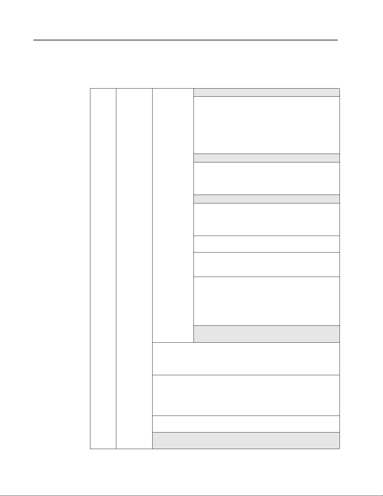
CLI command reference
The diagram below displays the available CLI commands and their hierarchical
structure.
Table 1. CLI command reference diagram
root --> 1. config --> 1. save
help
li
lo
save
2. diag --> 1. galpa
3. show --> 1. events
4. fw --> 1. tftp
5. reset
6. ?
2. sys --> 1. speed
2. mode
3. oserr
4. crcerr
5. blkarb
6. clkd
7. time
3. default
4. port --> 1. beacon
2. show
3. types
4. add
5. password
6. load --> 1. show
2. lbclr
3. delprt
4. addprt
7. trunk --> 1. addprt
2. delprt
8. network --> 1. reset
2. show
3. ip
9. zone --> 1. bzht
2. bzdt
3. addprt
4. delprt
5. showmem
6. act
10. ..
11. ?
5. delta
2. glim
3. os
4. ps
2. ptype
3. portinfo
4. prtctrs
5. clrctr
2. xmodem
6. showpri
7. prtctrs
8. clrctr
6. sysinfo
7. zninfo
8. lbinfo
9. os
10. galpa
3. revert
4. show
8. lipen
9. name
10. location
11. contact
12. syslog
13. events
14. sev
5. view
6. edit
7. del
8. type
5. delalpa
6. addalpa
7. ialpa
8. util
3. showmem
4. clr
4. mask
5. gateway
6. ..
7. deact
8. zstate
9. zclr
10. addblk
11. delblk
12. showblks
9. beacon
10. con
11. who
12. ialpa
11. glim
12. sensors
13. getcon
14. sync
15. dump
5. reset
6. ..
15. fault
16. evclr
17. clrled
18. ..
19. ?
9. ..
10. ?
9. pu1
10. pu2
11. ..
12. ?
5. ..
6. ?
7. ?
13. hz
14. bzr
15. alpas
16. ..
17. ?
13. ..
14. ?
16. sid
17. zalpas
18. ..
19. ?
7. ?
2006 Model L10 Storage Switch
6
Page 19

Root menu (root)
The Root menu is the CLI’s main menu. This menu is the first menu displayed after
entering the password and logging in to the CLI.
Menu commands
Table 2. Root menu commands
Command Description Additional Information
1. config Displays the Configuration sub-menu. See page 9.
2. diag Displays the Diagnostics sub-menu. See page 49.
3. show Displays the Show sub-menu. See page 55.
4. fw Displays the Firmware sub-menu. See page 63.
5. reset Resets the switch. See page 7.
6. ? Displays additional information on a
Hardware reset (reset)
This command resets the switch.
To reset the switch:
From the Root menu, type reset and press E
If changes have been made to the switch configuration, a message appears asking if the
current configuration should be saved.
To save changes and reset the switch, type y and press E
To reset the switch without saving changes, type n and press E
To cancel the request to reset the switch, type c and press E
Help (?)
This command displays the help description for a specific command.
To display help for specific command:
See page 7.
command.
NTER.
NTER.
NTER.
NTER.
Type ? <command> and press E
NTER.
Enter the command using one of the following methods:
• Type the actual command text. For example, under the Show menu, to view help for
the sysinfo command: type ? sysinfo and press E
NTER.
• Type the number of the command. For example, under the Show menu, to view help
for the sysinfo command: type ? 6 and press E
NTER.
• Type the first few letters of the command. For example, under the Show menu, to view
help for the sysinfo command: type ? sys and press E
NTER.
Chapter 1. Introduction
7
Page 20

2006 Model L10 Storage Switch
8
Page 21

Chapter 2. Configuration menu (root/config)
The Configuration menu provides menus and commands for configuring the switch,
ports, One-Step Zoning, Automatic Trunking, Load Balancing, and network settings.
Menu Commands
Table 3. Configuration menu commands
Command Description
1. save Saves the current system configuration. See page 9.
2. sys Displays the System Configuration sub-menu. See page 11.
3. default Resets the switch to the factory default settings. See page 9.
4. port Displays the Port Configuration sub-menu. See page 20.
5. password Changes the switch password. See page 10.
6. load Displays the Load Balancing Configuration sub-menu. See page 33.
7. trunk Displays the Trunking Configuration sub-menu. See page 37.
8. network Displays the Network Configuration sub-menu. See page 39.
9. zone Displays the Zone Configuration sub-menu. See page 41.
10. .. Returns to the previous menu. See page 10.
11. ? Displays additional information on a command. See page 10.
Saving the current system configuration (root/config/save)
Switch configuration settings (for example, zoning or port settings) can be saved to the
switch’s Flash memory to protect against loss of power. This command automatically
resets the switch.
Additional
Information
To save the current configuration:
1. From the Configuration menu (root/config), type save and press E
the current switch configuration settings.
A message prompt appears confirming the request.
2. Type y and press E
The current switch configuration is saved and the switch automatically resets.
NTER to proceed.
Setting the switch to factory defaults (root/config/default)
This command returns the switch to the factory default settings; however, the network
configuration and port type settings are retained.
To restore the factory default configuration:
1. From the Configuration menu (root/config), type default and press E
A message prompt appears confirming the request.
2. Type y and press E
© Copyright IBM Corp. 2004
NTER.
NTER to save all of
NTER.
9
Page 22

Changing the password (root/config/password)
This command enables you to change the password for modifying the switch’s
configuration. The same password is used to access both the CLI and the Web
Note: Until the default switch password is changed, any user with knowledge of the
default password can make changes to the switch’s configuration.
To change the password:
1. From the Configuration menu (root/config), type password and press E
A message prompt appears asking for the current password.
2. Type the current password and press E
If the correct password is entered, a message prompt appears asking for the new
password.
3. Type the new password and press E
Note: The password must be between 6 and 25 characters in length and is case
sensitive.
A message prompt appears asking for the new password to be entered again.
4. Type the new password and press E
The new password is saved and activated.
Return to previous menu (..)
This command enables you to return to the previous menu.
To return to the previous menu:
Type .. and press E
NTER.
NTER.
NTER.
NTER.
NTER.
Help (?)
This command displays the help description for a specific command.
To display help for specific command:
Type ? <command> and press E
Enter the command using one of the following methods:
• Type the actual command text. For example, under the Show menu, to view help for
• Type the number of the command. For example, under the Show menu, to view help
• Type the first few letters of the command. For example, under the Show menu, to view
2006 Model L10 Storage Switch
10
NTER.
the sysinfo command: type ? sysinfo and press E
for the sysinfo command: type ? 6 and press E
NTER.
NTER.
help for the sysinfo command: type ? sys and press E
NTER.
Page 23

System configuration menu (root/config/sys)
The System configuration menu provides commands to configure the switch settings.
Menu commands
Table 4. System configuration menu commands
Command Description
1. speed Configures the switch speed. See page 11.
2. mode Configures the switch mode. See page 12.
3. oserr Configures the OS Error Threshold. See page 12.
4. crcerr Configures the CRC Error Threshold. See page 13.
5. blkarb Configures the Blocking Arbitration AL_PA. See page 13.
6. clkd Configures the Clock Delta Threshold. See page 14.
7. time Configures the switch time. See page 14.
8. lipen Configures the Stealth Intelligent Change Manager See page 14.
9. name Configures the switch’s name. See page 15.
10. location Configures the switch’s location. See page 15.
11. contact Configures the contact information for the individual or
party managing the switch.
12. syslog Configure the switch for a system log server See page 16.
13. events Displays the event log. See page 18.
14. sev Configures the event log’s severity filter level. See page 18.
Additional
Information
See page 15.
15. fault Configures the event log’s severity fault threshold. See page 19.
16. evclr Clears the event log. See page 19.
17. clrled Clears the Fault LED. See page 19.
18. .. Returns to the previous menu. See page 10.
19. ? Displays additional information on a command. See page 10.
Setting the system speed (root/config/sys/speed)
This command sets the current speed per port at which the switch is running. All ports
operate at the same speed. The default setting is 2.125 Gb/s.
To change the switch speed:
Type speed <setting> and press E
Table 5. System speed settings
Setting Description
1 Set switch speed to 1.0625 Gb/s.
2 Set switch speed to 2.125 Gb/s.
NTER.
Chapter 2. Configuration menu (root/config)
11
Page 24

To view the current switch speed:
From the Root menu, type show sysinfo and press E
NTER.
Setting the system switching mode (root/config/sys/mode)
This command sets the switching or segmenting capability of the device, which allows
increased aggregate bandwidth and decreased latency by only routing data between
opened ports. The default setting is on (enabled).
Disabling the switching capability places the switch into a single shared loop (FC-AL
loop mode) similar to a Fibre Channel hub. In this mode, all port policies are disabled
and the ports share bandwidth.
To change the switch mode:
From the System Configuration menu (root/config/sys), type mode <setting> and
press E
Table 6. System switching modes
Setting Description
1 Set switch mode to on (enabled).
2 Set switch mode to off (disabled).
To view the current switch mode:
NTER.
From the Root menu, type show sysinfo and press E
NTER.
Configuring the OS Error Threshold (root/config/sys/oserr)
The Ordered Set Error Threshold is the maximum number of OS errors allowed in a 10second interval before a port is bypassed. Setting this value to ‘0’ returns the threshold
to the factory default setting. The default setting is 16777215.
To change the threshold:
1. From the System Configuration menu (root/config/sys), type oserr and press
E
NTER.
The current value appears in brackets before the command prompt.
2. Type the new value and press E
To view the current OS Error Threshold:
From the Root menu, type show sysinfo and press E
NTER. The valid range is from 0 to 16777215.
NTER.
2006 Model L10 Storage Switch
12
Page 25

Configuring the CRC Error Threshold (root/config/sys/crcerr)
The cyclic redundancy check (CRC) Error Threshold is the maximum number of CRC
errors allowed in a 10-second interval before a port is bypassed. Setting this value to ‘0’
returns the threshold to the factory default setting. The default setting is 3.
To change the threshold:
1. From the System Configuration menu (root/config/sys), type crcerr and press
E
NTER.
The current value appears in brackets before the command prompt.
2. Type the new value and press E
NTER. The valid range is from 0 to 255.
To view the current CRC Error Threshold:
From the Root menu, type show sysinfo and press E
NTER.
Setting the Blocking Arbitration AL_PA (root/config/sys/blkarb)
When two ports start a communication session, the Blocking ARB is sent to all other
ports trying to communicate with those ports until the connection is terminated. The
default setting is ‘FF’. If other connected devices use the ‘FF’ setting for a different
purpose, select another Blocking ARB value (for example, ‘FB’). Under normal
circumstances, this setting does not need to be modified.
To change the blocking ARB value:
1. From the System Configuration menu (root/config/sys), type blkarb and press
E
NTER.
The current value appears in brackets before the command prompt.
2. Type the desired selection (1-6) and press E
Table 7. Blocking Arbitration AL_PA
Setting Description
1 xF7
NTER.
2 xF8
3xFB
4xFD
5xFE
6xFF
To view the current Blocking Arbitration AL_PA:
From the Root menu, type show sysinfo and press E
Chapter 2. Configuration menu (root/config)
NTER.
13
Page 26

Configuring the Clock Delta Threshold (root/config/sys/clkd)
The Clock Delta is the amount of variance in frequency between the reference clock and
an input port. The Clock Delta Threshold sets the threshold that can be used by the
Clock Delta Policy to automatically bypass a port based on the frequency difference.
The default setting is 200.
To change the threshold:
1. From the System Configuration menu (root/config/sys), type clkd and press E
The current value appears in brackets before the command prompt.
2. Type the new value and press E
The valid range is from 10 to 1000 (units measured in PPM).
NTER.
Setting the system time (root/config/sys/time)
This command sets the switch’s current date and time for the box. The default setting is
01/01/1970 00:00:00.
Note: The date and time settings must be configured any time the switch loses power or
is reset, as the time settings are not retained
To change the date and time:
1. From the System Configuration menu (root/config/sys), type time and press E
The current time and date appear in brackets before the command prompt.
2. Type the new date and time (MM/DD/YYYY HR:MN:SC) and press E
To view the current system time:
From the Root menu, type show sysinfo and press E
NTER.
NTER.
NTER.
NTER.
Configuring the Stealth Intelligent Change Manager (root/config/sys/lipen)
This command displays the current Stealth Intelligent Change Manager setting and
allows you to enable or disable the Stealth Intelligent Change Manager. The Stealth
Intelligent Change Manager provides stability and control over change notification
disruptions on a port basis. The default setting is enabled.
To change the Stealth Intelligent Change Manager setting:
1. From the System Configuration menu (root/config/sys), type lipen and press E
The current setting appears in brackets before the command prompt.
2. Type the appropriate selection (1 or 2) and press E
Table 8. Stealth Intelligent Change Manager settings
Setting Description
1 enable
2 disable
2006 Model L10 Storage Switch
14
NTER.
NTER.
Page 27

Setting the switch name (root/config/sys/name)
This command sets the switch name. The name is limited to 79 characters and quotation
marks must wrap the entire name. For example, ‘Storage Switch #3’. The default setting
is ‘Storage Switch’.
To change the switch name:
1. From the System Configuration menu (root/config/sys), type name and press E
The current name appears in brackets before the command prompt.
2. Type the new name and press E
NTER.
To view the current switch name:
From the Root menu, type show sysinfo and press E
NTER.
Setting the switch location (root/config/sys/location)
This command sets the switch location. The location is limited to 79 characters and
quotation marks must wrap the entire location. For example, ‘Lab #1’. The default setting
is ‘None’.
To change the switch location:
1. From the System Configuration menu (root/config/sys), type location and press
E
NTER.
The current location appears in brackets before the command prompt.
2. Type the new location and press E
To view the current switch location:
From the Root menu, type show sysinfo and press E
NTER.
NTER.
NTER.
Setting the contact information (root/config/sys/contact)
This command sets the switch contact information. Contact information may be a name,
telephone number, or web site address. The contact information is limited to 79
characters and quotation marks must wrap the entire contact information. For example,
‘John Smith 425-555-1212’. The default setting is ‘IBM Technical Support’.
To change the switch contact information:
1. From the System Configuration menu (root/config/sys), type contact and press
E
NTER.
The contact information appears in brackets before the command prompt.
2. Type the new contact information and press E
To view the current switch contact information:
From the Root menu, type show sysinfo and press E
Chapter 2. Configuration menu (root/config)
NTER.
NTER.
15
Page 28

Configuring the switch for a system log server (root/config/sys/syslog)
This command configures the switch for a system log server that monitors switch events.
To configure the switch to communicate with a system log server:
1. From the System Configuration menu (root/config/sys), type syslog and press
E
NTER.
2. Type the appropriate selection (1-7) and press ENTER.
3. Enter the applicable setting and press E
Table 9. Switch settings for a system log server
Setting Description
1. IP Address The system log server’s IP address. The default value is 127.0.0.1.
2. Port The port number of the system log server. The port is usually set to
514. The default value is 514.
3. Name The name under which to log reports on the system log server. The
default value is "IBM".
4. Enable Enables the switch to send reports to the system log server (enable=1
or disable=2). The default value is 2 (disabled).
5. Facility The reporting group to send to the system log server. The default
setting is 1 [userLevelMessages].
The standard reporting groups are:
0 – kernelMessages
1 – userLevelMessages
2 – mailSystem
3 – systemDaemons
4 – securityAuthorizationMessages
5 – messagesGeneratedInternallyBySyslogd
6 – linePrinterSubsystem
7 – networkNewsSubsystem
8 – uucpSubsystem
9 – clockDaemon
10 – securityAuthorizationMessages
11 – ftpDaemon
12 – ntpSubsystem
13 – logAudit
14 – logAlert
15 – clockDaemon
16 – localUse0
17 – localUse1
18 – localUse2
19 – localUse3
20 – localUse4
21 – localUse5
22 – localUse6
23 – localUse7
NTER.
2006 Model L10 Storage Switch
16
Page 29

Table 9. Switch settings for a system log server (continued)
Setting Description
6. Severity
Threshold
The lowest severity level at which to send messages to the system log
server. Any messages that are equal to or higher in severity than the
specified severity level are sent to the system log server. For example,
if the severity level for system log reporting is designated as ‘alert’, the
switch logs messages of the ‘alert’ or the ‘emergency’ severity level
only—’emergency’ is the only severity level higher than ‘alert’. The
default setting is 6 (‘info’).
The severity levels include:
0 – emergency
1 – alert
2 – critical
3 – error
4 – warning
5 – notify
6 – info
7 – debug
7. Exit Setup Exits the setup menu.
To exit the setup menu:
Type 7 and press E
NTER.
The following table provides a list of the system log messages and their severities.
Table 10. System log server messages and severities
Message Severity
SFP Overvoltage. CRITICAL
Port # inserted. INFO
Port # bypassed. INFO
Temperature Over Max. ALERT
Temperature OK. INFO
Port # state change to Unknown. INFO
Port # state change to Inserted. INFO
Port # state change to Loopback. INFO
Port # state change to Byp-Tx Fault. INFO
Port # state change to Diag Transmit. INFO
Port # state change to Byp-LIP(f8,x). INFO
Port # state change to Byp-Timeout. INFO
Port # state change to Byp-Redundant. INFO
Port # state change to Byp-Rx LOS. INFO
Port # state change to Byp-Sync LOS. INFO
Port # state change to bypassed. INFO
Chapter 2. Configuration menu (root/config)
17
Page 30

Displaying events (root/config/sys/events)
This command displays the event log entries (up to 3000 messages) generated by the
switch. For a list of the severity levels and event messages, see Appendix A. Event
messages on page 67.
To view the event log:
From the System Configuration menu (root/config/sys), type events and press E
To continue to list event messages:
Press E
NTER.
To view all remaining event log messages:
Type a and press E
NTER.
To quit viewing the event log messages:
Press C
TRL-X.
Configuring the event log severity filter (root/config/sys/sev)
This command sets the event log’s severity filter level. When set, the event log will only
record events that are equal to or higher than the specified severity level. The default
setting is 7.
Each event has a particular severity level ranging between ‘emergency’ and ‘info’. Users
can designate the lowest severity level at which to report an event in the event log. (For
example, if the severity level for event log reporting is designated as ‘alert’, the switch
logs messages of the ‘alert’ or the ‘emergency’ severity level only—’emergency’ is the
only severity level higher than ‘alert’.)
NTER.
To change the event log severity level:
1. From the System Configuration menu (root/config/sys), type sev and press E
The current severity level value appears in brackets before the command prompt.
2. Type the desired selection (1-7) and press E
NTER.
Table 11. Event log severity filter settings
Setting Description
1 emergency
2 alert
3critical
4error
5 warning
6 notify
7info
NTER.
2006 Model L10 Storage Switch
18
Page 31

Configuring the event log severity fault threshold (root/config/sys/fault)
This command sets the threshold for when the Fault LED is triggered by an event. When
set, an event that is equal to or higher than the specified fault threshold will trigger the
switch’s Fault LED. The default setting is 3.
Each event has a particular severity level ranging between ‘emergency’ and ‘info’. Users
can designate the lowest severity level at which to trip the switch’s Fault LED.
To change the event log severity level:
1. From the System Configuration menu (root/config/sys), type fault and press E
The current fault threshold value appears in brackets before the command prompt.
2. Type the desired selection (1-7) and press E
Table 12. Event log severity fault threshold settings
Setting Description
1 emergency
2 alert
3critical
4error
5 warning
6 notify
7info
Clearing the event log (root/config/sys/evclr)
This command deletes all event log messages currently recorded in the log.
To delete the current list of event log messages:
NTER.
NTER.
1. From the System Configuration menu (root/config/sys), type evclr and press E
A message prompt appears confirming the request.
2. Type y and press E
The event log is cleared out and a new event message appears reporting the cleared
event log.
NTER.
Clearing the fault LED (root/config/sys/clrled)
This command clears the switch’s fault LED.
To clear the switch’s fault LED:
From the System Configuration menu (root/config/sys), type clrled and press E
The Fault LED turns off.
Chapter 2. Configuration menu (root/config)
NTER.
NTER.
19
Page 32

Port configuration menu (root/config/port)
The Port configuration menu provides commands to configure the port settings.
Menu commands
Table 13. Port configuration menu commands
Command Description
1. beacon Beacons a port. See page 20.
2. show Displays a port’s configuration. See page 21.
3. types Displays a port’s Smart Setting. See page 24.
4. view Displays the attributes for a Smart Setting. See page 26.
5. add Creates a custom Smart Setting. See page 31.
6. edit Edits a custom Smart Setting. See page 31.
7. del Deletes a custom Smart Setting. See page 31.
8. type Selects a Smart Setting. See page 32.
9. .. Returns to the previous menu. See page 10.
10. ? Displays additional information on a command. See page 10.
Beaconing ports (root/config/port/beacon)
This command flashes (beacons) a port’s LEDs to indicate the port needs attention. This
feature is typically used when troubleshooting port problems.
To view the current port beaconing settings:
Additional
Information
From the Port Configuration menu (root/config/port), type beacon and press E
To beacon a port:
From the Port Configuration menu (root/config/port), type beacon <port number> 1
and press E
Note: Multiple, consecutive ports can be specified by using a dash (-). For example, to
To stop beaconing a port:
From the Port Configuration menu (root/config/port), type beacon <port number> 2
and press E
2006 Model L10 Storage Switch
20
NTER.
NTER.
beacon ports 3, 4, and 5, type beacon 3-5 1.
NTER.
Page 33

Displaying port configuration information (root/config/port/show)
This command displays the port configuration and policy settings.
To view the port configuration and policy settings:
1. From the Port Configuration menu (root/config/port), type show and press E
A list of port configuration information appears for each port.
Table 14. Port configuration information
Field Description
Port # The port number.
State The current port state: bypassed, inserted, or rxLoss.
Type The topology among switches for a port.
• nonCascade– the default setting. No links exist between switches.
• Tree – allows arbitration fairness to other cascaded InSpeed-based
switches or ports connected to end devices. If the port is a tree port
then the ARB (Arbitrate) is sent down the port and, when the ARB is
received back, a connection is made between the source and
destination ports. All ports are viewed as 100% FC-AL compliant.
• String0 through String3 – designates the string to which a port is
assigned. Strings maintain fairness when two or more InSpeedbased storage switches are serially cascaded. When the destination
port is a string and an OPN is received, an ARB is transmitted
throughout the total string cascade to alert all devices to enforce
fairness rules. Therefore, if two devices try to ARB at the same time,
the higher Priority AL_PA will win the cascade first, the lower priority
one will follow.
Note: There may be no more than two string ports in a zone.
NTER.
Port Control The method for controlling a port.
• auto – the default setting. The switch will automatically insert a port
based on policy settings. This prevents the insertion of incompatible
ports, which may cause disruption.
• bypass – removes a port from the zone. Use this mode to keep a
device out of an initialization cycle when troubleshooting.
• extLoopback – removes a port from the zone and routes the port's
receive signal back through the port's transmitter. Use this mode to
isolate a specific zone for troubleshooting or test a transceiver’s
circuitry and attached media from the node end.
• insert – allows ports whose transceivers cannot derive a valid clock
or "K" character (ordered set) to join a zone. Use this mode
cautiously – devices without valid characters may put bad data into
the zone, causing the zone to go down.
Transmitter Enables or disables the transceiver connected to the port.
Chapter 2. Configuration menu (root/config)
21
Page 34

Table 14. Port configuration information (continued)
Field Description
LIP Ctrl Methods of change notification management.
• rxtxlip – no change notification management
• rxlip – devices attached to the port can receive change notifications
but will not propagate change notifications generated by that port to
other ports.
Note: Change notifications will be reflected back out of the port if
originated by devices attached to this port.
• txlip – propagates change notifications generated by the port to other
ports but will not allow devices attached to the port to receive
change notifications from other ports.
• nolip – blocks change notifications from being propagated from the
port and change notifications from devices on other ports to devices
on the port.
• Managed – Note: This setting should not be used unless directed to
do so by a customer service representative.
2. Press ENTER again to view the policy settings assigned to each port.
The policy settings for each port appear.
Table 15. Port information
Field Description
LIP on Insert The switch normally operates under the condition that when a
device is inserted onto the network, a change notification is
generated. However, this condition is not always true when
connecting hubs or switches together. In some instances, it is
possible to connect two zones together without the zones realizing
that multiple AL_PAs exist with the same values.
When this policy is enabled, the switch always generates a change
notification to ensure the proper system updates are performed.
However, when a device is removed (for example, an initiator or
target), the removal does not generate a change notification and
there are no system updates performed.
LIP on Removal This policy is similar to the Change Notification on Insertion policy,
except for the change notification being sent when a device is
removed rather than inserted.
When this policy is enabled, the switch always generates a change
notification to ensure the proper system updates are performed.
PTBI This policy ensures a device on a port is a valid, standards-
compliant participant before allowing the device to be inserted into
a zone. The device must meet all of the FC-AL requirements along
with going through a complete change notification cycle. During the
change notification cycle, the device becomes the Initialization
Master (IM) and goes through the change notification phases. Once
the change notification cycle is complete, the device can be
inserted. This process ensures a bad device is not allowed into the
zone.
2006 Model L10 Storage Switch
22
Page 35

Table 15. Port information (continued)
Field Description
LIPF8 Recovery When a port is already inserted into a zone, the port transforms F8
Failure notifications into F7 Initialization notifications. When this
occurs, the port is bypassed and F7 Initialization notifications are
allowed in the zone. Once the initialization is complete, the Bad
Zone Recovery Policy is operational and prevents a port that
continues to transmit F8 Failure notifications from inserting into the
zone.
Note: If this policy is disabled while the Bad Zone Recovery policy
is enabled, a zone that does go down will still allow the Bad
Zone Recovery policy to reset the zone and allow ports to
be reinserted.
When enabled, this policy prevents devices that send F8 Failure
notifications from inserting into a zone. The ability to remove
devices that generate F8 Failure notifications automatically and
instantaneously guarantees continual system operation.
When disabled, this policy allows devices that send F8 Failure
notifications to insert into a zone and does not consider F8 Failure
notifications when determining whether to insert a device or not.
SEOC Serial ID Exchange on Connect. This policy is an internal
diagnostic setting and should remain disabled.
Smart Insertion This policy is the default operating mode for all ports and
determines what the switch looks for prior to allowing a port to
insert into a zone. When the policy is enabled, an external device is
sent an F7 Initialization notification by the switch until an F7
Initialization notification is received from the device. Once an F7
Initialization notification is received, the port is inserted in the zone.
This policy takes precedence over all other policies. When this
policy is disabled, no additional policies are operational, and as
long as a port transmits a signal of the correct frequency and
amplitude, the port will be allowed in the zone.
Clear on Stall In situations where the switch is operating in switching mode, some
devices may fall into an operating mode where the device has
opened a target but has not released the connection to the target.
When this policy is enabled, the switch can detect this condition
and automatically recover when this situation arises.
No Comma The switch detects the amount of time a data stream has gone
without receiving a comma. The time setting is set to 100 (.001
seconds). When this policy is enabled, the switch bypasses the
disruptive port when the threshold is exceeded.
OS Err Ordered set (OS) errors are detected and counted for each
individual port. When this policy is enabled, a port is bypassed
when its OS count exceeds the threshold setting. The threshold
setting is based on the number of ordered set errors identified in 10
seconds.
Note: The threshold can be adjusted.
Chapter 2. Configuration menu (root/config)
23
Page 36

Table 15. Port information (continued)
Field Description
CRC Err Cyclic Redundancy Check (CRC) errors are detected and counted
for each individual port. When this policy is enabled, a port is
bypassed when its CRC count exceeds the threshold setting. The
threshold setting is based on the number of CRC errors identified in
10 seconds.
User intervention is required to return the port into the zone.
Recovery methods include replacing the defective component,
cycling power to the device on the port, removing and reinserting
the bypassed port, or cycling power to the switch.
Note: The threshold can be adjusted.
Clk Delta The switch determines the relative frequency of the signal being
received by a port to the internal switch clock. The result of this test
allows the determination of how far apart in frequency the switch’s
clock is in relation to the clock of the received signal – the clock
delta. If the clock delta exceeds a set threshold, the switch is
notified and the port may be bypassed if necessary. Typically, clock
drift is slow enough to allow the removal and replacement of a
defective part before the defective part begins to affect system
performance.
To quit viewing the settings:
Press C
TRL-X.
Displaying Smart Settings (root/config/port/types)
This command displays the available Smart Settings (port types). These default Smart
Settings were defined by Fibre Channel storage experts to ensure the switch is optimally
configured for performance and stability.
To view the Smart Settings:
From the Port Configuration menu (root/config/port), type types and press E
A list of the default Smart Settings appears.
Table 16. Smart Settings
Number Port Type
1 Initiator or Target
2 Initiator with Stealth
3 Target with Stealth
4 Fabric Connection
5 Tree Cascade
6 String Cascade--Trunk 1
7 String Cascade--Trunk 2
8 String Cascade--Trunk 3
9 String Cascade--Trunk 4
10 IBM Smart Setting
NTER.
2006 Model L10 Storage Switch
24
Page 37

Table 16. Smart Settings (continued)
Number Port Type
11 IBM Linux Initiator
12 IBM Linux Stealth Initiator
Default Smart Settings
The default Smart Settings cannot be modified or deleted, but these settings can be
used as templates for creating custom port types.
Note: Changing the port type may affect the performance or behavior of the system.
Depending on the implementation, some port types are better than others. For
questions regarding port type or cascade configuration, contact a customer
service representative.
Initiator or Target
This Smart Setting is the default setting for all switch ports from the factory. This setting
offers no change protection and all settings are set to their default values. Initiators and
targets can be connected to ports that are set to this Smart Setting.
This is the recommended Smart Setting for setups with targets and initiators connected
to a single switch.
Initiator with Stealth
This Smart Setting is used when connecting a host device to the port. When a port is set
to this Smart Setting, change notifications are not sent from the initiator to other devices,
but change notifications are received by the initiator.
This Smart Setting is appropriate for embedded storage controllers and external Host
Bus Adaptors (HBAs) or servers with installed HBAs.
Target with Stealth
This Smart Setting is used when connecting embedded storage devices, like JBOD
enclosures, SBOD™ enclosures, tape drives, or external RAID systems (JBOD
enclosures, SBOD enclosures, or tape libraries). When a port is set to this Smart
Setting, change notifications are sent to other devices, but change notifications are not
received by the target.
Fabric Connection
This Smart Setting is used when connecting a port to a Fabric switch. Only one
connection from the L10 storage switch to a Fabric switch is valid.
Tree Cascade
This Smart Setting is used when connecting two or more switches together in a tree
configuration. Up to four tree cascades are supported between switches.
String Cascade
This Smart Setting is used when connecting two switches together in a string
configuration. Up to four string cascades are supported between two switches.
Chapter 2. Configuration menu (root/config)
25
Page 38

Before selecting a cascade option, consider the following:
• Cascade ports of like number should be connected together. For example, connect
port 1 of Switch A to port 1 of Switch B.
• Cascade port numbers must be lower than non-cascade port numbers (for example,
Initiator or Target ports). Therefore, select cascade types before selecting these noncascade types.
• A maximum of two switches may be connected using string cascades.
IBM Smart Setting
This Smart Setting is a custom setting defined by IBM.
IBM Linux Initiator
This Smart Setting is a custom setting defined by IBM that has the Port Test Before
Insert (PTBI) policy disabled.
IBM Linux Stealth Initiator
This Smart Setting is a custom setting defined by IBM that has the Port Test Before
Insert (PTBI) policy disabled, and the Stealth Intelligent Change Manager feature is
enabled and set to “Only Receive Changes”.
Displaying Smart Setting attributes (root/config/port/view)
This command displays the attributes for a specific Smart Setting. See “Displaying
Smart Settings (root/config/port/types)” on page 24 for a list of port type numbers.
To view the Smart Setting attributes:
From the Port Configuration menu (root/config/port), type view <port type
number> and press E
The Smart Setting attributes include.
NTER.
2006 Model L10 Storage Switch
26
Page 39

Table 17. Smart Setting attributes
Attribute Description
Port Type Name The name of the port type setting. If using one of the
pre-defined port types, the name will automatically
appear.
Cascade Type The topology among switches for a port.
• Initiator or Target Port – the default setting. For when
there are no links among switches.
• Tree – allows arbitration fairness to other cascaded
InSpeed-based switches or ports connected to end
devices. If the port is a tree port then the ARB
(Arbitrate) is sent down the port and, when the ARB
is received back, a connection is made between the
source and destination ports. All ports are viewed as
100% FC-AL compliant.
• String0 through String3 – designates the string to
which a port is assigned. Strings maintain fairness
when two or more InSpeed-based storage switches
are serially cascaded. When the destination port is a
string and an OPN is received, an ARB is transmitted
throughout the total string cascade to alert all
devices to enforce fairness rules. Therefore, if two
devices try to ARB at the same time, the higher
Priority AL_PA will win the cascade first, the lower
priority one will follow.
Note: There may be no more than two string ports in a
zone.
Control The method for controlling a port.
• auto – the default setting. The switch will
automatically insert a port based on policy settings.
This prevents the insertion of incompatible ports,
which may cause disruption.
• bypass – removes a port from a zone. Use this mode
to keep a device out of an initialization cycle when
troubleshooting.
• extLoopback – removes a port from the zone and
routes the port's receive signal back through the
port's transmitter. Use this mode to isolate a specific
zone for troubleshooting or test a transceiver’s
circuitry and attached media from the node.
• insert – allows ports whose transceivers cannot
derive a valid clock or "K" character (ordered set) to
join the zone. Use this mode cautiously – devices
without valid characters may put bad data into the
zone, causing the zone to go down.
Transmitter Enables or disables the transceiver connected to the
port.
Chapter 2. Configuration menu (root/config)
27
Page 40

Table 17. Smart Setting attributes (continued)
Attribute Description
LIP on Insert Policy The switch normally operates under the condition that
when a device is inserted onto the network, a change
notification is generated. However, this condition is not
always true when connecting hubs or switches together.
In some instances, it is possible to connect two zones
together without the zones realizing that multiple
AL_PAs exist with the same values.
When this policy is enabled, the switch always
generates a change notification to ensure the proper
system updates are performed. However, when a device
is removed (for example, an initiator or target), the
removal does not generate a change notification and
there are no system updates performed.
LIP on Removal Policy This policy is similar to the Change Notification on
Insertion policy, except for the change notification being
sent when a device is removed rather than inserted.
When this policy is enabled, the switch always
generates a change notification to ensure the proper
system updates are performed.
Port Test Before Insert Policy This policy ensures a device on a port is a valid,
standards-compliant participant before allowing the
device to be inserted into a zone. The device must meet
all of the FC-AL requirements along with going through
a complete change notification cycle. During the change
notification cycle, the device becomes the Initialization
Master (IM) and goes through the change notification
phases. Once the change notification cycle is complete,
the device can be inserted. This process ensures a bad
device is not allowed into the zone.
2006 Model L10 Storage Switch
28
Page 41

Table 17. Smart Setting attributes (continued)
Attribute Description
LIP (F8) Recovery Policy When a port is already inserted into a zone, the port
transforms F8 Failure notifications into F7 Initialization
notifications. When this occurs, the port is bypassed
and F7 Initialization notifications are allowed in the
zone. Once the initialization is complete, the Bad Zone
Recovery Policy is operational and prevents a port that
continues to transmit F8 Failure notifications from
inserting into the zone.
Note: If this policy is disabled while the Bad Zone
Recovery policy is enabled, a zone that does go
down will still allow the Bad Zone Recovery
policy to reset the zone and allow ports to be
reinserted.
When enabled, this policy prevents devices that send
F8 Failure notifications from inserting into a zone. The
ability to remove devices that generate F8 Failure
notifications automatically and instantaneously
guarantees continual system operation.
When disabled, this policy allows devices that send F8
Failure notifications to insert into a zone and does not
consider F8 Failure notifications when determining
whether to insert a device or not.
SEOC Policy Serial ID Exchange on Connect. This policy is an
internal diagnostic setting and should remain disabled.
Smart Insertion Policy This policy is the default operating mode for all ports
and determines what the switch looks for prior to
allowing a port to insert into a zone. When the policy is
enabled, an external device is sent an F7 Initialization
notification by the switch until an F7 Initialization
notification is received from the device. Once an F7
Initialization notification is received, the port is inserted
in the zone.
This policy takes precedence over all other policies.
When this policy is disabled, no additional policies are
operational, and as long as a port transmits a signal of
the correct frequency and amplitude, the port will be
allowed in the zone.
Clear on Stall Policy In situations where the switch is operating in switching
mode, some devices may fall into an operating mode
where the device has opened a target but has not
released the connection to the target. When this policy
is enabled, the switch can detect this condition and
automatically recover when this situation arises.
Bypass on No Comma Policy The switch detects the amount of time a data stream
has gone without receiving a comma. The time setting
is set to 100 (.001 seconds). When this policy is
enabled, the switch bypasses the disruptive port when
the threshold is exceeded.
Chapter 2. Configuration menu (root/config)
29
Page 42

Table 17. Smart Setting attributes (continued)
Attribute Description
LIP Control Methods of change notification management.
• rxtxlip – no change notification management
• rxlip – devices attached to the port can receive
change notifications but will not propagate change
notifications generated by that port to other ports.
Note: Change notifications will be reflected back out of
the port if originated by devices attached to this
port.
• txlip – propagates change notifications generated by
the port to other ports but will not allow devices
attached to the port to receive change notifications
from other ports.
• nolip – blocks change notifications from being
propagated from the port and change notifications
from devices on other ports to devices on the port.
• Managed – Note: This setting should not be used
unless directed to do so by a customer service
representative.
Bypass on OS Error Policy Ordered set (OS) errors are detected and counted for
each individual port. When this policy is enabled, a port
is bypassed when its OS count exceeds the threshold
setting. The threshold setting is based on the number of
ordered set errors identified in 10 seconds.
Note: This threshold setting can be adjusted.
Bypass on CRC Error Policy Cyclic Redundancy Check (CRC) errors are detected
and counted for each individual port. When this policy is
enabled, a port is bypassed when its CRC count
exceeds the threshold setting. The threshold setting is
based on the number of CRC errors identified in 10
seconds.
User intervention is required to return the port into the
zone. Recovery methods include replacing the defective
component, cycling power to the device on the port,
removing and reinserting the bypassed port, or cycling
power to the switch.
Note: This threshold setting can be adjusted.
Bypass on Clock Delta
Policy
See the
User’s Guide
for the default settings for each Smart Setting.
The switch determines the relative frequency of the
signal being received by a port to the internal switch
clock. The result of this test allows the determination of
how far apart in frequency the switch’s clock is in
relation to the clock of the received signal – the clock
delta. If the clock delta exceeds a set threshold, the
switch is notified and the port may be bypassed if
necessary. Typically, clock drift is slow enough to allow
the removal and replacement of a defective part before
the defective part begins to affect system performance.
2006 Model L10 Storage Switch
30
Page 43

Creating a custom Smart Setting (root/config/port/add)
This command creates a new custom Smart Setting. The Smart Setting name can
contain any printable character except a comma ',' and may be up to 28 characters in
length. Spaces may be included in the name by wrapping the name with quotes. For
example, ‘custom HBA’.
To create a custom Smart Setting:
From the Port Configuration menu (root/config/port), type add <custom Smart
Setting name> and press E
The new Smart Setting is displayed with default attribute values.
To edit the new Smart Setting’s attributes:
NTER.
1. Type the number of the attribute (1-16) to change and press E
NTER.
A list of possible values appears.
2. Type the attribute value and press E
NTER.
3. Repeat steps 1 and 2 for the specific attributes to change.
4. When finished, type 17 and press E
NTER, or press CTRL-X to save the new Smart
Setting and its attributes.
Editing custom Smart Setting attributes (root/config/port/edit)
This command modifies an existing custom Smart Setting’s attributes.
To edit the attributes of a custom Smart Setting:
1. From the Port Configuration menu (root/config/port), type edit and press E
A list of custom Smart Settings and their associated numbers appears.
2. Type the number of the custom Smart Setting to edit and press E
The custom Smart Setting appears with its attribute values.
3. Type the number of the attribute (1-16) to change and press E
A list of possible values appears.
4. Type the attribute value and press E
NTER.
NTER.
NTER.
NTER.
5. Repeat steps 3 and 4 for the specific attributes to change.
6. When finished, type 17 and press E
NTER, or press CTRL-X to save the Smart Setting
and its attributes.
Deleting custom Smart Settings (root/config/port/del)
This command deletes a custom Smart Setting.
To delete a custom Smart Setting:
1. From the Port Configuration menu (root/config/port), type del and press E
2. A list of custom Smart Settings and their associated numbers appears.
Chapter 2. Configuration menu (root/config)
NTER.
31
Page 44

3. Type the number of the custom Smart Setting to delete and press ENTER.
4. A message box appears confirming the request.
5. Type y and press E
NTER to delete the custom Smart Setting.
Selecting Smart Settings (root/config/port/type)
This command selects a Smart Setting for a specified port. Select from the default
Smart Settings provided or select a custom Smart Setting.
To view the Smart Settings currently assigned to the ports:
From the Port Configuration menu (root/config/port), type type and press E
To assign a Smart Setting to a port:
From the Port Configuration menu (root/config/port), type type <the port number>
<the Smart Setting number> and press E
Note: To see a list of available Smart Settings, type types at the command prompt and
press E
NTER.
For example, to set Port 3 to the Tree Cascade Smart Setting (value=10), type type 3
10 and press E
NTER.
See “Displaying Smart Settings (root/config/port/types)” on page 24 for a list of Smart
Setting numbers.
NTER.
NTER.
2006 Model L10 Storage Switch
32
Page 45

Load Balancing configuration menu (root/config/load)
Load balancing builds on the Automatic Trunking functionality by specifying the path that
the data uses to flow between multiple switches. Users can manage the switch’s
aggregate bandwidth by manually distributing traffic across multiple cascade ports as
shown below. A cascade port is a port that is attached to another switch of the same
type and configured as a String or Tree Cascade Smart Setting. All data flows through
the primary cascade, unless the switch is configured differently.
Note: Cascade commands must be properly configured before load balancing will work.
Menu commands
Table 18. Load Balancing configuration menu
Command Description
1. show Displays trunk group members. See page 33.
2. lbclr Clears the trunk group configuration. See page 34.
3. delprt Removes one or more port members from the trunk
group.
4. addprt Adds one or more port members to the trunk group. See page 34.
5. delalpa Removes one or more AL_PA members from the
trunk group.
6. addalpa Adds one or more AL_PA members to the trunk
group.
7. ialpa Displays the Initiator AL_PAs. See page 35.
8. util Displays the high, average, and low utilization for
each port.
9. pu1 Displays the average port utilization interval. See page 36.
10. pu2 Displays the high/low port utilization interval. See page 36.
11. .. Returns to the previous menu. See page 10.
12. ? Displays additional information on a command. See page 10.
Additional
Information
See page 34.
See page 35.
See page 35.
See page 35.
Displaying trunk group members (root/config/load/show)
This command displays all port members and AL_PAs for a specific trunk group or for all
trunk groups.
To display the trunk group members for all ports:
From the Load Balancing configuration menu (root/config/load), type show and press
E
NTER.
To display the trunk group members for a specific port:
From the Load Balancing configuration menu (root/config/load), type show <port
number> and press E
NTER.
Chapter 2. Configuration menu (root/config)
33
Page 46

To clear the trunk group members for a specific port:
From the Load Balancing configuration menu (root/config/load), type lbclr <port
number> and press E
NTER.
Clearing trunk group configurations (root/config/load/lbclr)
This command clears all members from being associated with a specific trunk group
port. To remove all port members from all trunk groups, use 0 as the port number. When
members are removed from a specific trunk group, the members will return to the
primary trunk.
To clear the trunk group members for all ports:
From the Load Balancing configuration menu (root/config/load), type lbclr 0 and
press E
To clear the trunk group members for a specific port:
From the Load Balancing configuration menu (root/config/load), type lbclr <port
number> and press E
NTER.
NTER.
Deleting port members from trunk groups (root/config/load/delprt)
This command removes a specific port member from a trunk group. When a member is
removed from a specific trunk group, the member will return to the primary trunk.
To delete a port member from a specific trunk group:
From the Load Balancing configuration menu (root/config/load), type delprt
<cascade port number> <port member> and press E
Note: To delete multiple port members, use spaces or commas between port members.
NTER.
Adding port members to trunk groups (root/config/load/addprt)
This command sets the port members associated with a trunk group port for load
balancing. There are two ways members can be associated with a port: by port or by
AL_PA. By associating a member to a port, if that port is an active trunk group port, then
members associated with that port will be routed on that port.
To add a port member to a specific trunk group:
From the Load Balancing configuration menu (root/config/load), type addprt
<cascade port number> <port members> and press E
Note: To add multiple port members, use spaces or commas between port members.
NTER.
2006 Model L10 Storage Switch
34
Page 47

Deleting AL_PA members from trunk groups (root/config/load/delalpa)
This command removes a specified AL_PA member from a trunk group. Once removed
from the trunk group, the AL_PA returns to using the primary trunk.
To delete an AL_PA member from a specific trunk group:
From the Load Balancing configuration menu (root/config/load), type delalpa
<cascade port number> <AL_PA member> and press E
Note: To delete multiple port members, use spaces or commas between port members.
NTER.
Adding AL_PA members to trunk groups (root/config/load/addalpa)
This command sets the AL_PA members associated with a trunk group for load
balancing. Once assigned to a specific trunk group, the AL_PA uses the specified trunk
for all traffic flow.
To add an AL_PA member to a specific trunk group:
From the Load Balancing configuration menu (root/config/load), type addalpa
<cascade port number> <AL_PA member> and press E
Note: To add multiple port members, use spaces or commas between port members.
NTER.
Displaying initiator AL_PAs (root/config/load/ialpa)
This command displays the AL_PAs that have been detected as initiators. This
information is useful when configuring load balancing.
To display Initiator AL_PA members:
From the Load Balancing configuration menu (root/config/load), type ialpa and press
E
NTER.
Displaying port utilization (root/config/load/util)
Port utilization measures the amount of traffic running out of a port. For example, if an
initiator is transmitting data to a target, the initiator port displays a port utilization value
(%) while the target port does not. If the same initiator is receiving data from the target,
the target port displays a port utilization value (%) while the initiator port displays does
not.
The Port Utilization page displays port utilization for the latest completed intervals based
on high, average, and low percentage utilization.
Table 19. Port utilization information
Value Description
High The high percentage of data communication through a port over a
period of time (measured in seconds).
Average The average percentage of data communication through a port over a
period of time (measured in seconds).
Chapter 2. Configuration menu (root/config)
35
Page 48

Table 19. Port utilization information (continued)
Value Description
Low The low percentage of data communication through a port over a
period of time (measured in seconds).
To view port utilization for all ports:
From the Load Balancing configuration menu (root/config/load), type util and press
E
NTER.
A list of the port utilization percentages for the High, Average, and Low levels appears.
To view port utilization for a specific port:
From the Load Balancing configuration menu (root/config/load), type util <port
number> and press E
NTER.
A list of the port utilization percentages for the High, Average, and Low levels for that
specific port appears.
Displaying the average port utilization interval (root/config/load/pu1)
This command sets the number of seconds to sample a port for determining average
utilization percentage.
To view the average port utilization interval for all ports:
From the Load Balancing configuration menu (root/config/load), type pu1 and press
E
NTER.
To adjust the average port utilization interval for a port:
1. From the Load Balancing configuration menu (root/config/load), type pu1 <port
number (1-20)> <interval in seconds (5-3600)> and press E
2. Adjust the interval for consecutive ports by separating the ports with a dash (-). For
example, to set the interval for ports 5 through 10 to 100 seconds, type pu1 5-10
100 and press E
NTER.
Displaying the high/low port utilization interval (root/config/load/pu2)
This command sets the number of seconds to sample a port for determining the highest
and lowest utilization percentage.
To view the high/low port utilization interval for all ports:
From the Load Balancing configuration menu (root/config/load), type pu2 and press
E
NTER.
To adjust the high/low port utilization interval for a port:
1. From the Load Balancing Configuration menu (root/config/load), type pu2 <port
number (1-20)> <interval in seconds (5-3600)> and press E
NTER.
NTER.
2. Adjust the interval for consecutive ports by separating the ports with a dash (-). For
2006 Model L10 Storage Switch
36
example, to set the interval for ports 5 through 10 to 100 seconds, type pu2 5-10
100 and press E
NTER.
Page 49

Automatic Trunking configuration menu (root/config/trunk)
Multiple links between switches are called ‘trunks’. Trunks provide higher bandwidth
across cascaded switches for systems incorporating multiple initiators. Each trunk can
improve system throughput and provide ‘failover’ capability. A maximum of 4 trunks
between each switch is supported. Trunking is performed automatically when ports are
configured properly.
Each trunk is part of a trunk group. A trunk group consists of two or more cascades
between two switches. There can only be one trunk group between two switches. Each
trunk group contains a primary trunk. All traffic flows through the primary trunk on a
switch unless specified otherwise using the Load Balancing feature. The primary trunk is
always the lowest numbered port of any trunk group.
If the primary trunk fails, the secondary trunk automatically becomes the primary trunk
unless otherwise configured. Multiple cascades also enable switch configuration for
better performance through load balancing (see "Load Balancing" on page 33).
The Automatic Trunking configuration menu enables you to configure trunking by
defining trunk groups and assigning ports to those groups.
Menu commands
Table 20. Automatic Trunking configuration menu commands
Command Description
1. addprt Adds one or more port members to a trunk port. See page 37.
2. delprt Removes one or more port members from a trunk
port.
3. showmem Displays the port members on a trunk port. See page 38.
4. clr Clears one or more trunk ports. See page 38.
5. .. Returns to the previous menu. See page 10.
6. ? Displays additional information on a command. See page 10.
Additional
Information
See page 38.
Adding port members to trunk groups (root/config/trunk/addprt)
This command adds port members to a trunk group.
To add a port to a trunk:
From the Trunking configuration menu (root/config/trunk), type addprt <trunk group
number> <port members> and press E
Note: To add multiple port member, use commas between port members.
For example, to add ports 3, 5, and 7 to trunk group 1:
NTER.
From the Trunking configuration menu (root/config/trunk), type addprt 1 3,5,7 and
press E
Note: This feature should be used with caution as it will override any automated
NTER.
trunking selection already present on the switch. In addition, the automatic
features for detecting cascade connections will be disabled.
Chapter 2. Configuration menu (root/config)
37
Page 50

Deleting ports members from trunk groups (root/config/trunk/delprt)
This command removes port members from a trunk group. In order to delete a member,
the member must be explicitly removed from the trunk group.
To delete a port from a trunk group:
From the Trunking configuration menu (root/config/trunk), type delprt <trunk group
number> <port members> and press E
Note: To delete multiple port members, use commas between port members.
For example, to remove port members 5 and 7 from trunk group 1, which contains port
members 3, 5, and 7:
NTER.
Type delprt 1 5,7 and press E
NTER.
Displaying port members on a trunk group (root/config/trunk/showmem)
This command displays the port members within a specific trunk group.
To display the port members in a specific trunk group:
From the Trunking configuration menu (root/config/trunk), type showmem <trunk
group number> and press E
To display the port members for all trunk groups:
From the Trunking configuration menu (root/config/trunk), type showmem and press
E
NTER.
NTER.
Clearing trunk groups (root/config/trunk/clr)
This command clears all members from a specific trunk group. To remove all members
from all trunk groups, use 0 as the trunk group number.
To clear the port members for all trunk groups:
From the Trunking configuration menu (root/config/trunk), type clr 0 and press E
NTER.
To clear the port members for a specific trunk group:
From the Trunking configuration menu (root/config/trunk), type clr <trunk group
number> and press E
2006 Model L10 Storage Switch
38
NTER.
Page 51

Network configuration menu (root/config/network)
The Network configuration menu displays the current network settings and provides
commands for configuring the switch’s network settings.
Menu commands
Table 21. Network configuration menu commands
Command Description
1. reset Resets the switch. See page 39.
2. show Displays the current network settings. See page 39.
3. ip Configures the IP Address setting. See page 40.
4. mask Configures the network mask setting. See page 40.
5. gateway Configures the default gateway settings. See page 40.
6. .. Returns to the previous menu. See page 10.
7. ? Displays additional information on a command. See page 10.
Hardware reset (root/config/network/reset)
This command resets the switch.
To reset the switch:
1. From the Network configuration menu (root/config/network), type reset and press
E
NTER.
If any changes have been made to the switch configuration, a message appears
confirming the request to save the current configuration.
Additional
Information
2. To save changes and reset the switch, type y and press E
To reset the switch without saving changes, type n and press E
To cancel the request to reset the switch, type c and press E
NTER.
Displaying network settings (root/config/network/show)
This command displays the current and saved network settings for the switch, including
the IP address, gateway, and netmask. The Current settings are the settings used by the
switch at this time. The New settings are the settings that will be used by the switch the
next time it is reset.
To view the network settings:
From the Network configuration menu (root/config/network), type show and press
E
NTER.
The default IP settings are:
• IP Address: 192.168.1.129
• Netmask: 255.255.255.0
• Gateway: 192.168.1.1
Chapter 2. Configuration menu (root/config)
NTER.
NTER.
39
Page 52

Configuring the IP address setting (root/config/network/ip)
This command configures the IP address for the switch. The IP address format should
be separated by periods. For example, 196.168.1.129.
To change the IP address setting:
1. From the Network configuration menu (root/config/network), type ip and press
E
NTER.
The switch’s current IP address setting appears in brackets before the command
prompt.
2. Type the new IP address and press E
The switch’s IP address is now saved and becomes active once the switch is reset.
NTER.
Configuring the network mask setting (root/config/network/mask)
This command configures the network mask setting for the switch. These changes will
become active once the switch is reset. The network mask format should be separated
by periods. For example, 255.255.255.0.
To change the network mask setting:
1. From the Network configuration menu (root/config/network), type mask and press
E
NTER.
The switch’s current network mask setting appears in brackets before the command
prompt.
2. Type the new network mask setting and press E
The switch’s network mask setting is saved and becomes active once the switch is
reset.
NTER.
Configuring the gateway setting (root/config/network/gateway)
This command configures the default gateway setting for the switch. These changes will
become active once the switch is reset. The network mask format should be separated
by periods. For example, 196.168.1.1.
To change the default gateway setting:
1. From the Network configuration menu (root/config/network), type gateway and press
2. Type the new default gateway setting and press E
2006 Model L10 Storage Switch
40
E
NTER.
The switch’s current default gateway setting appears in brackets before the command
prompt.
NTER.
The switch’s default gateway setting is saved and becomes active once the switch is
reset.
Page 53

One-Step Zoning configuration menu (root/config/zone)
One-Step Zoning allows ports to be divided into multiple virtual zones (or work groups),
similar to Virtual Local Area Networking (VLAN). By separating activity on the network,
zoning also eliminates change notification propagation (change notifications that occur
within one zone cannot propagate to other zones.)
Use zoning to:
• Separate different operating system environments.
• Temporarily block or grant access during backup or other tasks.
• Consolidate equipment logically.
• Designate closed user groups for increased security.
• Separate test or maintenance areas from production areas.
Menu commands
Table 22. One-Step Zoning configuration menu commands
Command Description
1. bzht Configures the Bad Zone Reset Hold Time setting. See page 42.
2. bzdt Configures the Bad Zone Delay Time setting. See page 42.
3. addprt Adds one or more port members to a zone. See page 42.
4. delprt Removes one or more port members from a zone. See page 43.
5. showmem Displays the port members within a zone. See page 43.
6. act Activates the zone set. See page 43.
7. deact Deactivates the zone set. See page 43.
8. zstate Displays the state of specified zone. See page 44.
9. zclr Clears one or more zones. See page 44.
10. addblk Adds an AL_PA blocking member to a group. See page 44.
11. delblk Removes an AL_PA block member from a group. See page 46.
12. showblks Displays the AL_PA blocking groups. See page 46.
13. hz Configures the Hard Zone policy setting. See page 46.
14. bzr Configures the Bad Zone Recovery policy setting. See page 47.
15. alpas Displays the zone AL_PAs. See page 48.
Additional
Information
16. .. Returns to the previous menu. See page 10.
17. ? Displays additional information on a command. See page 10.
Chapter 2. Configuration menu (root/config)
41
Page 54

Setting the Bad Zone Recovery Reset Hold Time (root/config/zone/bzht)
The Bad Zone Recovery Hold Time is the amount of time that the switch keeps the ports
in bypass mode before attempting to re-insert the ports into the zone. This setting is
measured in milliseconds (.001 seconds). The default Reset Hold Time setting is 100.
To change the time interval:
1. From the Zoning configuration menu (root/config/zone), type bzht and press E
The current time interval appears in brackets before the command prompt.
2. Type the new time interval and press E
milliseconds (mSec).
NTER. The valid range is 10 to 1000
Setting the Bad Zone Recovery Delay Time (root/config/zone/bzdt)
The Bad Zone Recovery Delay Time is the amount of time that the switch waits after a
zone goes down before attempting to recover the zone. This setting is measured in
seconds. The default Delay Time setting is 5.
To change the time interval:
1. From the Zoning configuration menu (root/config/zone), type bzdt and press E
The current time interval appears in brackets before the command prompt.
2. Type the new time interval and press E
NTER. The valid range is 1 to 32 seconds.
Adding a port member to a zone (root/config/zone/addprt)
This command adds a port to a zone. Each port may be added to zones 1-11. Zone 0 is
the default zone and is not user definable. Zone 0 contains all ports not included in
zones 1-11.
NTER.
NTER.
When displaying the zone information and zoning is not active, Zone 0 displays all ports.
If zoning is active, Zone 0 only shows the ports currently active in Zone 0.
Note: Changes to zone configurations require that zoning be active. See “Activating
To add a port to a zone:
From the Zoning configuration menu (root/config/zone), type addprt <zone number>
<port numbers> and press E
Note: To add multiple port members, use spaces or commas between port members.
For example: If Zone 1 will consist of an HBA (port 3) and two targets (ports 5 and 7)
then to create Zone 1, type addprt 1 3,5,7 and press E
2006 Model L10 Storage Switch
42
zoning (root/config/zone/act)” on page 43.
NTER.
NTER.
Page 55

Removing a port member from a zone (root/config/zone/delprt)
This command deletes a port from a zone. Each port may belong to zones 1-11. Ports
cannot be deleted from Zone 0 since zone 0 is a special zone managed by the unit.
Zone 0 contains all of the ports not associated with other zones.
If zoning is not active, then zone 0 displays all ports. If zoning is active, zone 0 only
shows those ports not included in other zones.
Note: Changes to zone configurations require that zoning be active. See “Activating
zoning (root/config/zone/act)” on page 43.
To remove a port from a zone:
From the Zoning configuration menu (root/config/zone), type delprt <zone number>
<port numbers> and press E
Note: To delete multiple port members, use spaces or commas between port members.
For example: If Zone 1 consists of an HBA (port 3) and two targets (ports 5 and 7). then
to remove the target on port 7, type delprt 1 7 and press E
NTER.
NTER.
Displaying port members within a zone (root/config/zone/showmem)
This command displays the port members for a specified zone or for all zones. Zone 0 is
the default zone and is managed by the switch. Zone 0 shows the current active
configuration in the unit.
If zoning is not active, zone 0 displays all ports. If zoning is active, zone 0 only shows
those members not in the other zones.
To view the ports in all zones:
From the Zoning configuration menu (root/config/zone), type showmem and press E
To view the ports in a specific zone:
From the Zoning Configuration menu (root/config/zone), type showmem <zone
number> and press E
NTER.
Activating zoning (root/config/zone/act)
This command activates zoning on the switch. If zoning is not active, this command sets
up the corresponding hardware to enforce the defined zones. If zoning is already active,
this command reloads the zoning parameters.
To activate zoning:
From the Zoning configuration menu (root/config/zone), type act and press E
Deactivating zoning (root/config/zone/deact)
This command deactivates zoning on the switch. If zoning is active, this command
places all ports into a normal, non-zoned state.
NTER.
NTER.
To deactivate zoning:
From the Zoning configuration menu (root/config/zone), type deact and press E
Chapter 2. Configuration menu (root/config)
NTER.
43
Page 56

Displaying the zone state (root/config/zone/zstate)
This command displays the current zone state for a specified zone or all zones. The
zone state may be "up" (operational) or "down" (non-operational).
To view the zone state for all zones:
From the Zoning Configuration menu (root/config/zone), type zstate and press E
To view the zone state for a specific zone:
From the Zoning configuration menu (root/config/zone), type zstate <zone number>
and press E
NTER.
Clearing zones (root/config/zone/zclr)
This command clears out the port members from a specified zone. If the specified zone
is 0, it will clear all of the zones.
To clear a specific zone:
From the Zoning Configuration menu (root/config/zone), type zclr <zone number>
and press E
To clear all zones:
From the Zoning configuration menu (root/config/zone), type zclr 0 and press E
NTER.
Adding an AL_PA blocking member to a group (root/config/zone/addblk)
This command adds an AL_PA member to an AL_PA blocking group to set up a route
blocking zone and prevent devices (using AL_PAs) from accessing one another.
NTER.
NTER.
AL_PA zoning fully ensures that devices will not access each other. It does this by
blocking a group of devices from sending OPN signals to each other but allows the
devices to send OPNs outside of the group. This group of devices is called a "route block
zone", not to be confused with the port zones discussed earlier. Port zoning without
route blocking makes the separated ports unaware of each other, but this does not
prevent all OPN signals from getting through. Therefore, it is recommended that you
create a route block zone and include any AL_PAs that should not access each other.
Note: Zoning must be activated for route blocking to work properly.
2006 Model L10 Storage Switch
44
Page 57

Using the example in Figure 2, suppose you want to restrict Host 1 from accessing
sensitive data on Drive 2. AL_PAs 01 and E8 should be added to a route block zone.
l100037
Figure 2. Route block zone
To add an AL_PA member to a blocking group:
From the Zoning configuration menu (root/config/zone), type addblk <group
number> <AL_PA member> and press E
NTER
Note: Changes to zone configurations require that zoning be active. See “Activating
zoning (root/config/zone/act)” on page 43.
For example: There are two HBAs and a target connected to a switch and you want to
isolate the HBAs so that they do not see one another.
• HBA1 (Port 1, AL_PA 02).
• HBA2 (Port 2, AL_PA 04).
• Target1 (Port 3, AL_PA EF).
To block the HBAs from seeing each other:
1. Type addblk 1 02 and press E
NTER.
This adds HBA1 to blocking group 1.
2. Type addblk 1 04 and press E
NTER.
This adds HBA2 to blocking group 1.
Note: If the AL_PAs are on the same port, the switch will not be able to block access
3. Ensure zoning is activated and reset the switch for the changes to become active on
the switch.
Chapter 2. Configuration menu (root/config)
45
Page 58

Removing an AL_PA blocking member from a group (root/config/zone/delblk)
This command deletes an AL_PA member from an AL_PA blocking group.
To remove an AL_PA member from a blocking group:
From the Zoning configuration menu (root/config/zone), type delblk <group
number> <AL_PA member> and press E
Note: Changes to blocking configurations require that zoning be active. See “Activating
zoning (root/config/zone/act)” on page 43.
For example: There are two HBAs in blocking group 1 and you want to remove HBA2
from the blocking group.
• HBA1 (Port 1, AL_PA 02).
• HBA2 (Port 2, AL_PA 04).
To remove HBA2 from blocking group 1:
NTER.
1. Type delblk 1 04 and press E
This removes HBA2 from blocking group 1.
2. Ensure zoning is activated and reset the switch for the changes to become active on
the switch.
NTER.
Displaying AL_PA blocking groups (root/config/zone/showblks)
This command displays the route blocking configuration for all route blocking groups.
To view the AL_PA blocking groups:
From the Zoning configuration menu (root/config/zone), type showblks and press
E
NTER.
Configuring the Hard Zone policy (root/config/zone/hz)
This command displays and configures the hard zone policy for a specific zone.
Note: Zone 0 is reserved and cannot be configured for hard zoning.
A hard zone can be used to add a separate 126 AL_PAs that operate in isolation from
any other zone. A hard zone disables switching functionality and creates a shared
connection between the ports in a zone topology, splitting the switch into multiple unique
FC-AL zones. When hard zoning is enabled, all switch zones must be hard zones. A
combination of hard zones and regular zones on a single switch is not allowed.
Note: Do not set a hard zone for ports in multiple zones or share ports that have the
The advantages of hard zoning include:
• Each hard zone contains 126 available AL_PAs.
• The switch can be configured to contain up to eleven isolated hard zones.
2006 Model L10 Storage Switch
46
Hard Zone option set. This will cause errors that do not log an event or display a
message.
Page 59

The limitations of hard zoning include:
• 2 Gb of shared bandwidth over the entire hard zone.
• Ports in a hard zone cannot use the Stealth Intelligent Change Manager.
• Automatic Trunking and route blocking are not allowed in a hard zone.
• Ports in a hard zone cannot be set to a string or tree cascade configuration.
• Device AL_PAs on a port in a hard zone cannot be displayed.
To view the current hard zone policy for each zone:
From the Zoning configuration menu (root/config/zone), type hz and press E
To configure the hard zone policy for a specific zone:
1. From the Zoning configuration menu (root/config/zone), type hz <zone number>
<policy setting> and press E
NTER.
Table 23. Hard Zone policy settings
Policy Setting Description
1 Enable hard zoning.
2 Disable hard zoning.
2. Ensure zoning is activated and reset the switch for the changes to become active on
the switch.
Configuring the Bad Zone Recovery policy (root/config/zone/bzr)
This command displays and configures the bad zone recovery policy for a specific zone.
This policy automatically recovers traffic after a device has brought down the zone. The
switch continuously watches the state of each zone and detects when a failed zone has
not recovered on its own. The switch then bypasses and re-inserts every port within the
zone. However, the Port Test Before Insertion (PTBI) policy does not allow the offending
port to re-insert the zone, which allows all other devices to operate normally.
NTER.
Note: Bad zone recovery is enabled by default. If bad zone recovery is disabled, use
the following instructions to enable this policy for the appropriate zones.
To view the current bad zone recovery policy for each zone:
From the Zoning configuration menu (root/config/zone), type bzr and press E
NTER.
To configure the bad zone recovery policy for a specific zone:
1. From the Zoning configuration menu (root/config/zone), type bzr <zone number>
<policy setting> and press E
NTER.
Table 24. Bad Zone Recovery policy settings
Policy Setting Description
1 Enable the Bad Zone Recovery policy.
2 Disable the Bad Zone Recovery policy.
2. Ensure zoning is activated and reset the switch for the changes to become active on
the switch.
Chapter 2. Configuration menu (root/config)
47
Page 60

Displaying zone AL_PAs (config/zone/alpas)
This command displays the AL_PAs for a specific zone or for all zones.
To view the AL_PAs for all zones:
From the Zoning configuration menu (root/config/zone), type alpas and press E
To view the AL_PAs for a specific zone:
From the Zoning configuration menu (root/config/zone), type alpas <zone number>
and press E
NTER.
NTER.
2006 Model L10 Storage Switch
48
Page 61

Chapter 3. Diagnostics menu (root/diag)
The Diagnostics menu provides commands for determining and correcting issues with
normal switch operation.
Menu commands
Table 25. Diagnostic menu commands
Command Description
1. galpa Displays the port AL_PAs. See page 49.
2. glim Displays the Zone Initialization Master port. See page 49.
3. os Displays the detected ordered sets. See page 50.
4. ps Displays the port state. See page 51.
5. delta Displays the port clock delta. See page 51.
6. showpri Displays the primary ports and the associated
duplicates.
7. prtctrs Displays the error counters for one or more ports. See page 52.
8. clrctr Clears the counters. See page 52.
9. beacon Beacons a port. See page 52.
10. con Displays information on the connected device. See page 53.
11. who Displays information on the device that caused a
change notification.
12. ialpa Displays the Initiator AL_PAs. See page 53.
13. .. Returns to the previous menu. See page 10.
14. ? Displays additional information on a command. See page 10.
Additional
Information
See page 52.
See page 53.
Displaying port AL_PAs (root/diag/galpa)
This command displays all AL_PAs for a single port or for all ports.
To view the AL_PAs for all ports:
From the Diagnostics menu (root/diag), type galpa and press E
To view the AL_PAs for a specific port:
From the Diagnostics menu (root/diag), type galpa <port number> and press E
Displaying LIM port (root/diag/glim)
This command displays the Loop Initialization Master (LIM) port for a single zone or for
all zones. The LIM port is responsible for starting the change notification process in
each zone.
To view the LIM ports for all zones:
From the Diagnostics menu (root/diag), type glim and press E
© Copyright IBM Corp. 2004
NTER.
NTER.
NTER.
49
Page 62

To view the LIM port for a specific zone:
From the Diagnostics menu (root/diag), type glim <zone number> and press E
Displaying detected ordered sets (root/diag/os)
This command displays the detected ordered sets for a single port or for all ports.
To view the detected ordered sets for all ports:
From the Diagnostics menu (root/diag), type os and press E
To view the detected ordered sets for a specific port:
From the Diagnostics menu (root/diag), type os <port number> and press E
A list of detections and their indications follows:
Table 26. Detected ordered sets
Detection Indication
User Match The ordered set or pattern selected under the Match area
has been detected.
EOF (End of Frame) An End-of-Frame (EOF) delimiter has been detected;
frames are present. (An EOF immediately follows the CRC
of a frame and signals the frame’s end.)
SOF (Start of Frame) A Start-of-Frame (SOF) delimiter has been detected;
frames are present.
NTER.
NTER.
NTER.
Idle Sequences of IDLEs are being transmitted to maintain link
activity; no other data is being transmitted.
ARBFF ARB(FF)s are being transmitted to maintain link activity; no
other data is being transmitted.
ARB A port is arbitrating for network access to perform a task.
RRDY (Read Ready) The receiving node on this port has sent an R_RDY signal,
indicating that it is ready for a frame to be transmitted over
the link.
CLS (Close) The port is attempting to begin the process of closing the
current FC-AL circuit.
OPN (Open) The port is attempting to open communications with another
port.
Note: As is the case with some ordered sets, an OPN may
not go all the way around the FC-AL, instead
stopping at its destination.
2006 Model L10 Storage Switch
50
Page 63

Table 26. Detected ordered sets (continued)
Detection Indication
LIPF8 (F8 Failure) A non-switching port has detected a failure on its receive
input, is notifying other ports, and is determining whether
the network is still operational.
Some events that could cause the port to detect network
failure follow:
• A device has failed.
• A device has been powered off.
• The physical connection between the transmitter and
receiver is broken.
• Activating the port bypass circuit does not typically result
in a network failure.
LIPF7 (F7 Initialization) A port is in the non-participating mode and is attempting to
win arbitration and begin initialization, possibly because the
port was reset or is powering up. Sometimes the port is
sending this sequence to another hot-cascaded switch, like
a new initiator being inserted in the network.
LIP (Change
Notification)
Unknown The switch cannot determine what is being transmitted.
Invalid An invalid transmit word has been detected.
CRC Error A Frame CRC error has been detected.
PT to PT (Point-to-Point) A point-to-point connection has been detected.
A change notification has been detected and action has
been taken.
Displaying port state (root/diag/ps)
This command displays the port states and conditions for a single port or for all ports.
To view the port state and condition for all ports:
From the Diagnostics menu (root/diag), type ps and press E
To view the port state and condition for a specific port:
From the Diagnostics menu (root/diag), type ps <port number> and press E
Displaying port clock delta (root/diag/delta)
This command displays the port clock deltas for a single port or for all ports. The port
clock delta is the difference (in parts per million) between the internal clock and the
received clock signal on the port.
NTER.
NTER.
To view the port clock delta for all ports:
From the Diagnostics menu (root/diag), type delta and press E
To view the port clock delta for a specific port:
From the Diagnostics menu (root/diag), type delta <port number> and press E
Chapter 3. Diagnostics menu (root/diag)
NTER.
NTER.
51
Page 64

Displaying primary ports (root/diag/showpri)
This command displays the primary ports and associated duplicates for a single port or
for all ports.
To view the primary port and associated duplicates for all ports:
From the Diagnostics menu (root/diag), type showpri and press E
To view the primary port and associated duplicates for a specific port:
From the Diagnostics menu (root/diag), type showpri <port number> and press
E
NTER.
Displaying port error counters (root/diag/prtctrs)
This command displays the ordered set, CRC, and Insertion errors for a single port or for
all ports.
To view the errors for all ports:
From the Diagnostics menu (root/diag), type prtctrs and press E
To view the errors for a specific port:
From the Diagnostics menu (root/diag), type prtctrs <port number> and press
E
NTER.
Clearing counters (root/diag/clrctr)
This command clears the port counters.
To clear the error counters for all ports:
NTER.
NTER.
From the Diagnostics menu (root/diag), type clrctr and press E
Beaconing ports (root/diag/beacon)
This command flashes (beacons) a port’s LEDs to indicate that the port needs attention.
Typically used when troubleshooting port problems.
To view the current port beaconing settings:
From the Diagnostics menu (root/diag), type beacon and press E
To beacon a port:
From the Diagnostics menu (root/diag), type beacon <port number> 1 and press
E
NTER.
The port’s LEDs start flashing.
To stop beaconing a port:
From the Diagnostics menu (root/diag), type beacon <port number> 2 and press
E
NTER. The port’s LEDs return to normal operation.
Multiple, consecutive ports can be specified by using a dash (-). For example, to beacon
ports 3, 4, and 5, type beacon 3-5 1.
NTER.
NTER.
2006 Model L10 Storage Switch
52
Page 65

Displaying connected device information (root/diag/con)
This command displays the connected device information including the device ID,
connected port number, and Stealth settings for one or more ports.
To view device information for all ports:
From the Diagnostics menu (root/diag), type con and press E
To view device information for a specific port:
From the Diagnostics menu (root/diag), type con <port number> and press E
NTER.
Displaying change notification information (root/diag/who)
Displays the port number from which the last change notification initiated.
To view the port:
From the Diagnostics menu (root/diag), type who and press E
NTER.
Displaying initiator AL_PAs (root/diag/ialpa)
This command displays the AL_PAs that have been detected by the switch and identified
as initiators. Initiators are detected when a device is opened.
To view the initiator AL_PAs:
From the Diagnostics menu (root/diag), type ialpa and press E
NTER.
NTER.
Chapter 3. Diagnostics menu (root/diag)
53
Page 66

2006 Model L10 Storage Switch
54
Page 67

Chapter 4. Show menu (root/show)
Users can view all of the switch’s current settings (including system, port, zone, and
version settings) at either the Show menu or, for some settings, the specific submenu.
The Show menu provides information on current switch settings.
Menu commands
Table 27. Show menu commands
Command Description
1. events Displays the event log. See page 55.
2. ptype Displays the attributes for a Smart Setting. See page 56.
3. portinfo Displays port configuration information. See page 56.
4. prtctrs Displays the error counters for one or more ports. See page 56.
5. clrctr Clears the counters. See page 56.
6. sysinfo Displays system information. See page 57.
7. zninfo Displays zone information. See page 58.
8. lbinfo Displays load balancing information. See page 58.
9. os Displays the detected ordered sets. See page 59.
10. galpa Displays the port AL_PAs. See page 59.
11. glim Displays the Loop Initialization Master (LIM) port. See page 59.
12. sensors Displays sensor information. See page 59.
13. getcon Displays the connected device ID. See page 60.
14. sync Displays the PLL lock status. See page 60.
15. dump Displays the switch settings. See page 60.
Additional
Information
16. sid Displays the SFP serial data. See page 61.
17. zalpas Displays the zone AL_PAs. See page 61.
18. .. Returns to the previous menu. See page 10.
19. ? Displays additional information on a command. See page 10.
Displaying events (root/show/events)
This command displays the event log entries (up to 3000 messages) generated by the
switch. For a list of the severity levels and event messages, see Appendix A. Event
messages on page 67.
To view the event log:
From the Show menu (root/show), type events and press E
To continue to list event messages:
Press E
© Copyright IBM Corp. 2004
NTER.
NTER.
55
Page 68

To view all remaining event log messages:
Type a and press E
NTER.
To quit viewing the event log messages:
Press C
TRL-X.
Displaying Smart Settings (root/show/ptype)
This command displays the available Smart Settings (port types). For a list of available
Smart Settings, see the
User’s Guide
.
To view the Smart Settings:
From the Show menu (root/show), type view <port type number> and press
E
NTER.
Displaying port configuration information (root/show/portinfo)
This command displays the port configuration and policy settings.
To view the port configuration and policy settings:
1. From the Show menu (root/show), type show and press E
A list of port configuration information appears for each port.
2. Press E
NTER again to view the policy settings assigned to each port.
NTER.
The policy settings for each port appear.
To quit viewing the settings:
Press C
TRL-X.
For additional information on the port configuration and policy settings, see the
Guide
.
Displaying port error counters (root/show/prtctrs)
This command displays the ordered set, CRC, and Insertion errors for a single port or for
all ports.
To view the errors for all ports:
From the Show menu (root/show), type prtctrs and press E
To view the errors for a specific port:
From the Show menu (root/show), type prtctrs <port number> and press E
Clearing counters (root/show/clrctr)
This command clears the port counters.
To clear the error counters for all ports:
User’s
NTER.
NTER.
From the Show menu (root/show), type clrctr and press E
2006 Model L10 Storage Switch
56
NTER.
Page 69

Displaying system information (root/show/sysinfo)
This command displays the current switch information.
To display current switch information:
From the Show menu (root/show), type sysinfo and press E
The system information includes the following:
NTER.
Table 28. System information
Setting Description
System Name The name assigned to the switch.
Location The location assigned to the switch.
MAC ID A unique device address (MAC address) assigned to each
switch at the factory. Cannot be configured or modified.
Serial Number A unique identification number assigned to each switch at the
factory. This field can only be configured or modified on Field
Replaceable Units (FRUs).
Switching Mode When ‘on’, the switch is able to direct data to specific ports
using full bandwidth. When ‘off’, bandwidth is split among the
ports and data is sent around the network as in a shared FCAL architecture.
OS Error Threshold The maximum number of OS errors allowed in a 10-second
interval before a port is bypassed. Setting this value to ‘0’
uses the factory default setting.
CRC Error Threshold The maximum number of CRC errors allowed in a 10-second
interval before a port is bypassed. Setting this value to ‘0’
uses the factory default setting.
Blocking Arbitration When two ports start a communication session, the Blocking
ARB is sent to all other ports trying to communicate with
those ports until the connection is terminated. The default
setting is ‘FF’. If other connected devices use the ‘FF’ setting
for another purpose, select another Blocking ARB value (for
example, ‘FB’).
Switch FW Version The current firmware loaded onto the switch. The current
version can be replaced by an alternate version that you have
previously loaded onto the switch.
SOC Version The SOC 320 version that is used in the switch. Cannot be
configured or modified.
Switch HW Version The hardware version of the switch. Cannot be configured or
modified.
MIB Version The proprietary Management Information Base version that is
supported through SMP. Cannot be configured or modified.
Speed The current speed per port at which the switch is running. All
ports operate at the same speed. The default switch speed is
set to 2.125 Gb/s.
Chapter 4. Show menu (root/show)
57
Page 70

Table 28. System information (continued)
Setting Description
Fault Status The current status of the switch.
InSpeed SOC Status The current status of the InSpeed SOC chipset.
Current Time The switch’s current date and time.
System Up Time The duration of time that the switch has been operational. If
the switch is rebooted or power is cycled, this value is reset.
IP Address The current IP Address for the switch.
Netmask The current IP Netmask address for the switch.
Default Gateway The current Gateway address for the switch.
Displaying zone information (root/show/zninfo)
This command displays zone status (enabled or disabled) and current zone information,
including the zone number, current state, LIM, and Up Count.
To view zone information:
From the Show menu (root/show), type zninfo and press E
NTER.
Displaying Load Balancing information (root/show/lbinfo)
This command displays the current load balancing information, including port number,
port members, and associated AL_PAs.
To view load balancing information:
1. From the Show menu (root/show), type lbinfo and press E
A list of ports and their associated port members and AL_PAs appears.
2. Press E
A list of ports and their associated modes and utilization percentages appears.
NTER to continue.
Table 29. Load Balancing information
Value Description
Mode (1) timeOpen–When switching mode is enabled, this value
measures the percentage of time that the port is involved in a
connection, regardless of the amount of data that is being
sent.
(2) framesSeen–When switching mode is disabled, this value
measures the amount of frame data passing through the port.
NTER.
Utilization (%) Displays the utilization percentage for each port based on the
2006 Model L10 Storage Switch
58
mode.
Page 71

Displaying detected ordered sets (root/show/os)
This command displays the detected ordered sets for a single port or for all ports.
To view the detected ordered sets for all ports:
From the Show menu (root/show), type os and press E
To view the detected ordered sets for a specific port:
From the Show menu (root/show), type os <port number> and press E
For a list of ordered set detections and their indications, see Chapter 3: Displaying
detected ordered sets (root/diag/os) on page 50.
Displaying port AL_PAs (root/show/galpa)
This command displays all of the AL_PAs for a single port or for all ports. This
information is useful when configuring load balancing and route blocking.
To view the AL_PAs for all ports:
From the Show menu (root/show), type galpa and press E
To view the AL_PAs for a specific port:
From the Show menu (root/show), type galpa <port number> and press E
Displaying LIM port (root/show/glim)
This command displays the Loop Initialization Master (LIM) port for a single zone or for
all zones. The LIM port is responsible for starting the change notification process in
each zone.
NTER.
NTER.
NTER.
NTER.
To view the LIM ports for all zones:
From the Show menu (root/show), type glim and press E
To view the LIM port for a specific zone:
From the Show menu (root/show), type glim <zone number> and press E
Displaying sensor information (root/show/sensors)
This command displays switch sensor information, including enclosure temperature and
fan status.
To view switch sensor information:
From the Show menu (root/show), type sensors and press E
NTER.
NTER.
NTER.
Chapter 4. Show menu (root/show)
59
Page 72

Table 30. Sensor information
Setting Indicator
Enclosure Temperature Nominal (green)–the switch temperature is within the normal
operating range.
OverTemp (red)–the enclosure temperature has exceeded
the recommended operating range (above 45
Fan Nominal (green)–the fan unit is working properly.
Not Present (yellow)–the fan unit has been removed or
cannot be detected.
Fault (red)–the fan unit has stopped operating.
Displaying connected device IDs (root/show/getcon)
This command displays the type of connection for a single port or for all ports. A
connection type of SEOC means that the switch has discovered and successfully
connected to a SEOC-enabled device.
To view the connected device IDs for all ports:
o
C).
From the Show menu (root/show), type getcon and press E
To view the connected device ID for a specific port:
From the Show menu (root/show), type getcon <port number> and press E
Displaying PLL lock status (root/show/sync)
This command displays the Phase Loop Lock (PLL) status for a single port or for all
ports. The PLL indicates whether the port is operational or not.
To view the synchronization status for all ports:
From the Show menu (root/show), type sync and press E
To view the synchronization status for a specific port:
From the Show menu (root/show), type sync <port number> and press E
Displaying switch settings (root/show/dump)
This command displays the current switch settings in XML-tagged format.
Note: This command generates and outputs a significant amount of data. It may take
some time before results are displayed.
NTER.
NTER.
NTER.
NTER.
To view the switch settings:
1. From the Show menu (root/show), type dump and press E
2. Type y and press E
2006 Model L10 Storage Switch
60
NTER.
A message appears confirming the request.
NTER.
Page 73

Note: HyperTerminal® users can capture the entire switch setting display by enabling
the text capture feature. To enable this feature, click Transfer > Capture Text and
designate the location and filename for the file. Once this feature is enabled,
proceed with the instructions above. When the system is finished downloading
the switch information, open the text file to view the settings.
Displaying SFP serial ID information (root/show/sid)
This command displays information (if available) about an inserted SFP transmitter for a
specific port.
To view the SF serial data for a specific port:
From the Show menu (root/show), type sid <port number> and press E
Displaying zone AL_PAs (root/show/zalpas)
This command displays AL_PAs for a single zone or for all zones.
To view the AL_PAs for all zones:
From the Show menu (root/show), type zalpas and press E
To view the AL_PAs for a specific zone:
From the Show menu (root/show), type zalpas <zone number> and press E
NTER.
NTER.
NTER.
Chapter 4. Show menu (root/show)
61
Page 74

2006 Model L10 Storage Switch
62
Page 75

Chapter 5. Firmware menu (root/fw)
This section displays the current and alternate firmware versions, enables you to select
which firmware version to run the next time the switch is reset, and provides a means to
load new firmware on the switch.
Menu commands
Table 31. Firmware menu commands
Command Description
1. tftp Loads a new firmware image using TFTP. See page 63.
2. xmodem Loads a new firmware image using XMODEM. See page 64.
3. revert Changes the alternate image to the active image
after the switch is reset.
4. show Displays the current firmware information. See page 65.
5. reset Resets the switch. See page 65.
6. .. Returns to the previous menu. See page 10.
7. ? Displays additional information on a command. See page 10.
Loading a new image using TFTP (root/fw/tftp)
This command loads a new firmware image from the host system to the switch through a
Trivial File Transfer Protocol (TFTP) server on the switch.
To download firmware from a binary file using TFTP:
1. From the Firmware menu (root/fw), type tftp and press E
message appears:
Start TFTP Transfer to m: from host shell.
Additional
Information
See page 65.
NTER. The following
Example: c:\tftp -i 192.168.11.171 put filename.bin m:
After transfer, select one of the following:
1) Verify and Store
2) Abort
Figure 3. TFTP download message
2. For Windows workstations, open a new DOS window and locate the directory
containing the new firmware, type the following (where
Address and
tftp -i <IPaddress> put <filename.bin> m: and press E
Within a few seconds, the “Transfer successful” message appears in the window. (If
this message does not appear, verify that the file location and name were properly
entered, and repeat the transfer.)
3. In the terminal session window, type
The “Program Load Successful” message appears.
© Copyright IBM Corp. 2004
filename
IPaddress
is the name of the binary firmware file):
1 to verify and store the new firmware.
is the switch’s IP
NTER.
63
Page 76

4. Type show and press ENTER.
The active and alternate firmware versions appear.
5. Type reset to reboot the switch to activate the new image.
Unix Instructions
Unix users should replace step #2 above with the following instructions:
1. At a Unix prompt, type tftp <IPaddress> (where IPaddress
Address) and press E
2. Type binary and press E
3. Type put <filename> /ram (where filename
file) and press E
NTER.
NTER.
is the name of the binary firmware
NTER.
A message appears confirming that the file was sent.
4. Type quit and press E
NTER.
Loading a new image using Xmodem (root/fw/xmodem)
This command loads a new firmware image from the host system to the switch using the
®
HyperTerminal
Note: The HyperTerminal session’s baud rate should be set to 115200 for Xmodem
transfers. To configure the baud setting, click File > Properties. Under the
Settings tab, click Configure and set the bits per second to 115200.
If a connection to the switch is already established, disconnect from the switch
before changing the baud setting.
To download firmware using HyperTerminal via the serial port:
1. From the Firmware menu (root/fw), type xmodem and press E
The following message appears:
Within serial console, start image download using
XMODEM file transfer protocol.
program and the serial port.
is the switch’s IP
NTER.
2. In HyperTerminal, click Transfer > Send File.
3. Set the protocol to Xmodem.
4. Click Browse to locate the firmware file on the host system.
5. Double-click the firmware filename to select it and click Send.
2006 Model L10 Storage Switch
64
--------------------------------------------
XMODEM - File Transfer Facility
--------------------------------------------
Send several Control-X characters to cancel.
Figure 4. XMODEM download start message
After the firmware is downloaded, the following message appears:
Change baud rate back to 19200 ?(y/n):
Figure 5. XMODEM download baud rate message
Page 77

6. Type y and press ENTER.
The following message appears:
Transfer Complete. Verifying file integrity....
Verification Complete. Copying to Flash.............
Flash Copy Complete.
Download Complete.
New image will become active upon reset.
OK
Figure 6. XMODEM download complete message
7. Type show and press E
NTER.
The active and alternate firmware versions appear.
8. Type revert and press E
NTER to use the alternate firmware image (the new image
that was downloaded) the next time the switch is reset.
9. Type reset and press E
NTER to reboot the switch to activate the new image.
Changing firmware images (root/fw/revert)
This command sets the alternate image to become the active image on the next switch
reset.
To revert to the alternate firmware image:
From the Firmware menu (root/fw), type revert and press E
Displaying current firmware information (root/fw/show)
This command displays information for the current active, alternate, and boot firmware
images.
To view the current firmware information:
From the Firmware menu (root/fw), type show and press E
Internal Firmware Versions:
------------------------------------------------------
ACTIVE: V2.08 (build 2) Jun 2 2004 23:59:32
ALTERNATE: V2.08 (build 1) May 24 2004 03:32:06
BOOT: V1.00 (build 1) May 24 2004 03:32:01
NTER.
NTER.
Figure 7. Firmware information display
Hardware reset (root/fw/reset)
This command resets the switch hardware.
To reset the switch:
1. From the Firmware menu (root/fw), type reset and press E
If any changes have been made to the switch configuration, a message appears
confirming the request to save the current configuration.
NTER.
Chapter 5. Firmware menu (root/fw)
65
Page 78

2. To save changes and reset the switch, type y and press ENTER.
To reset the switch without saving changes, type n and press E
To cancel the request to reset the switch, type c and press E
NTER.
NTER.
2006 Model L10 Storage Switch
66
Page 79

Appendix A. Event messages
The L10 storage switch’s event messages are listed below. For explanations, contact a
customer service representative. The message’s applicable severity level as defined
below are given before each message.
Table 32. Event message severity levels
Severity Level Severity Description
1 EMERG Immediate action required; system failing
2 ALERT Unrecoverable condition reported; major event in
3 CRIT Event failed with possible loss of integrity
4 ERR Condition failed; action required
5 WRN Failed event occurred; no action required
6 NOTIFY Configuration error or abnormal event occurred; no
7 INFO Event occurred; no action required
These severity levels can be used to designate which events trigger trap messages.
Using the Command Line Interface (CLI), you can designate the minimum severity level
of events to be logged in the Event Log and at which to illuminate the switch’s Fault LED.
progress
action required
Table 33. Event messages
Event Event Message Severity
1 Message log cleared INFO
5 Power Supply Failed ALERT
6 Power Supply Online NOTIFY
9 Fan has stopped EMERG
10 Fan has returned ALERT
19 Temperatures over limit ALERT
20 Temperature OK INFO
50 SPF Overvoltage EMERG
54 SOC has detected a CRC error in the EEPROM NOTIFY
70 Port # bypassed NOTIFY
71 Port # inserted NOTIFY
72 Transceiver detected at Port # NOTIFY
73 Transceiver removed at Port # NOTIFY
74 SEOC occurred on Port # NOTIFY
75 Port # exceeded OS threshold NOTIFY
76 Port # exceeded CRC threshold NOTIFY
77 Loop UP on Port # NOTIFY
78 Loop DOWN on Port # NOTIFY
79 Port # received a LIP(F8) WRN
80 Port # CRC Error detected in frame WRN
81 Port # did not receive LIPF7) within timeout WRN
© Copyright IBM Corp. 2004
67
Page 80

Table 33. Event messages (continued)
Event Event Message Severity
83 Segment stall on Port # NOTIFY
84 Bad Open on Port # WRN
85 Error during Port Disc. NOTIFY
86 Port # PTBI failed due to timeout NOTIFY
87 Port # changed to <state> NOTIFY
88 Transceiver in Port # has been cycled NOTIFY
89 Port # has cycled between insert/bypassed (not
necessarily in that order)
90 Loop CYCLED on Port # NOTIFY
91 Port exceeded Clk Delta threshold INFO
95 Interframe has been received INFO
96 Interswitch link added/removed INFO
97 LIP Cycle Timeout INFO
98 API Initialized OK INFO
99 Selftest failure ERR
100 Received Unknown event INFO
101 CRC detected on either an ISL LIP or Generic
Frame
107 Trap task failed to update trap destination info. CRIT
135 CLI level 1 password changed NOTIFY
136 CLI level password changed to default setting NOTIFY
150 Web level 1 password changed NOTIFY
151 Web password level changed to default setting NOTIFY
165 System config reset to factory default ERR
166 New Port Config Type added NOTIFY
167 Port Config Type deleted NOTIFY
168 Current Config saved to flash NOTIFY
169 Error in saving config file to flash ERR
170 Error in retrieving config information ERR
171 Config File successfully configured system NOTIFY
172 Error in initializing system with config file ERR
198 A device tried to access another device that was
not in the same zone
199 Health timer has expired on Zone # NOTIFY
208 Port # is over threshold NOTIFY
218 Trunk DOWN on Port # NOTIFY
219 Trunk UP on Port # NOTIFY
220 New Primary Trunk NOTIFY
NOTIFY
NOTIFY
NOTIFY
2006 Model L10 Storage Switch
68
Page 81

Appendix B. Default Smart Setting attributes
Table 34. Default Smart Setting attributes
Cascade
Type
Control
Transmitter
LIP on
Insert
Policy
LIP on
Removal
Policy
Device
Test
Before
Insert
Policy
LIP (F8)
Recover
Policy
SEOC
Policy
Smart
Insertion Policy
Clear on
Stall Policy
Bypass
on No
Comma
Policy
LIP Control
Bypass
on
OS Error
Policy
Bypass
on CRC
Error
Policy
Bypass
on Clock
Delta
Policy
Initiator
nonCas-
cade
auto auto auto auto auto auto auto auto auto auto auto auto
enabled enabled enabled enabled enabled enabled enabled enabled enabled enabled enabled enabled
enabled enabled enabled enabled enabled enabled enabled enabled enabled enabled enabled enabled
enabled enabled enabled enabled enabled enabled enabled enabled enabled enabled enabled enabled
enabled enabled enabled disabled disabled disabled disabled disabled disabled enabled disabled disabled
disabled enabled disabled disabled disabled disabled disabled disabled disabled disabled disabled disabled
disabled disabled disabled disabled disabled disabled disabled disabled disabled disabled disabled disabled
enabled enabled enabled enabled enabled enabled enabled enabled enabled enabled enabled enabled
enabled enabled enabled enabled enabled enabled enabled enabled enabled enabled enabled enabled
enabled enabled enabled enabled enabled enabled enabled enabled enabled enabled enabled enabled
rxtxlip rxlip txlip rxtxlip nolip nolip nolip nolip nolip rxtxlip rxtxlip rxlip
disabled disabled disabled disabled disabled disabled disabled disabled disabled disabled disabled disabled
disabled disabled disabled disabled disabled disabled disabled disabled disabled disabled disabled disabled
disabled disabled disabled disabled disabled disabled disabled disabled disabled disabled disabled disabled
or Target
Initiator
nonCas-
cade
Tar ge t
with Stealth
nonCas-
cade
Fabric
with Stealth
Connection
tree tree string0 string1 string2 string3 nonCas-
Tree Cascade
--Trunk 1
String Cascade
--Trunk 2
String Cascade
--Trunk 3
String Cascade
--Trunk 4
String Cascade
IBM Smart
cade
Setting
Initiator
IBM Linux
nonCas-
cade
IBM Linux
nonCas-
cade
Stealth Initiator
© Copyright IBM Corp. 2004
69
Page 82

2006 Model L10 Storage Switch
70
Page 83

Appendix C. AL_PA cross references
Arbitrated Loop Physical Addresses
AL_PA AL_PA ID AL_PA AL_PA ID AL_PA AL_PA ID
(hex) (hex) (decimal) (hex) (hex) (decimal) (hex) (hex) (decimal)
EF 00 0 A3 2B 43 4D 56 86
E8 01 1 9F 2C 44 4C 57 87
E4 02 2 9E 2D 45 4B 58 88
E2 03 3 9D 2E 46 4A 59 89
E1 04 4 9B 2F 47 49 5A 90
E0 05 5 98 30 48 47 5B 91
DC 06 6 97 31 49 46 5C 92
DA 07 7 90 32 50 45 5D 93
D9 08 8 8F 33 51 43 5E 94
D6 09 9 88 34 52 3C 5F 95
D5 0A 10 84 35 53 3A 60 96
D4 0B 11 82 36 54 39 61 97
D3 0C 12 81 37 55 36 62 98
D2 0D 13 80 38 56 35 63 99
D1 0E 14 7C 39 57 34 64 100
CE 0F 15 7A 3A 58 33 65 101
CD 10 16 79 3B 59 32 66 102
CC 11 17 76 3C 60 31 67 103
CB 12 18 75 3D 61 2E 68 104
CA 13 19 74 3E 62 2D 69 105
C9 14 20 73 3F 63 2C 6A 106
C7 15 21 72 40 64 2B 6B 107
C6 16 22 71 41 65 2A 6C 108
C5 17 23 6E 42 66 29 6D 109
C3 18 24 6D 43 67 27 6E 110
BC 19 25 6C 44 68 26 6F 111
BA 1A 26 6B 45 69 25 70 112
B9 1B 27 6A 46 70 23 71 113
B6 1C 28 69 47 71 1F 72 114
B5 1D 29 67 48 72 1E 73 115
B4 1E 30 66 49 73 1D 74 116
B3 1F 31 65 4A 74 1B 75 117
B2 20 32 63 4B 75 18 76 118
B1 21 33 5C 4C 76 17 77 119
AE 22 34 5A 4D 77 10 78 120
AD 23 35 59 4E 78 0F 79 121
AC 24 36 56 4F 79 08 7A 122
AB 25 37 55 50 80 04 7B 123
AA 26 38 54 51 81 02 7C 124
A9 27 39 53 52 82 01 7D 125
A7 28 40 52 53 83 00 7E 126
A6 29 41 51 54 84 --- 7F 127
A5 2A 42 4E 55 85 --- --- ---
© Copyright IBM Corp. 2004
71
Page 84

2006 Model L10 Storage Switch
72
Page 85

Glossary
Table 35. Glossary
AL_PA or Arbitrated
Loop Physical Address
Arbitration The process of selecting one respondent from a group
Close (CLS) An Arbitrated Loop protocol used to terminate a loop
Current Fill Word The fill word that the Loop Port State Machine uses when
Duplex Cable Two fibers in one cable suitable for duplex transmission.
Fiber Optics Light transmission through optical fibers for
Fibre Channel Fibre Channel is a data transfer interface technology that
LED Light-emitting diode. A status indicator on a switch.
Gb/s Gigabits per second.
Node An entity with one or more N_Ports or NL_Ports.
Open (OPN) An Arbitrated Loop protocol used to establish a loop
Protocol A data transmission convention which may include timing,
SCSI Small computer system interface. Standard interface for
SFP Small form-factor pluggable transceiver. These
Topology The logical and/or physical arrangement of stations on a
Transceiver A device that converts one form of signaling to another for
A one-byte value used to identify a port in an Arbitrated
Loop topology. The value of the AL_PA corresponds to bits
7:0 of the 24-bit Native Address Identifier.
requesting service at the same time.
circuit.
a fill word is to be transmitted.
communication or signaling.
maps several common transport protocols including IP
and SCSI, allowing it to merge high-speed I/O and
networking functionality in a single connectivity
technology. Fibre channel is an open standard as defined
by ANSI and OSI standards and operates over copper and
fiber optic cabling at distances of up to 10 kilometers. It is
unique in its support of multiple interoperable topologies
including point-to-point, arbitrated-loop and switching and
it offers several qualities of service for network
optimization. With its large packet sizes, Fibre Channel is
ideal for storage, video, graphic and mass data transfer
applications.
circuit.
control, formatting, error detection with correction and
data representation.
storage modules.
transceivers are fully compliant with FC-PI and MSA
standards and occupy less than half the board space of
the existing GBIC products.
network. Fibre Channel topologies include point-to-point,
Arbitrated Loop, and switched fabric.
both transmission and reception. SFPs and GBICs are
transceivers.
© Copyright IBM Corp. 2004
73
Page 86

2006 Model L10 Storage Switch
74
Page 87

Index
A
activating zoning 43
adding
AL_PA blocking members to group
AL_PA members
port members to trunk groups
port members to zone
Smart Settings
trunk group members
additional information
AL_PA Cross References
AL_PAs
displaying
Initiator
assistance
Automatic Trunking
adding port members
clearing trunk groups
deleting port members
displaying port members
Automatic Trunking Configuration menu
addprt command
clr command
delprt command
showmem command
59
53
x, 10
35
37
42
31
34
ix
71
37
38
38
38
37
38
38
38
B
Bad Zone Recovery
configuring
Delay time
Reset Hold time
beaconing ports
blocking Arb
Bypass on Clock Delta Policy
Bypass on CRC Error Policy
Bypass on No Comma Policy
Bypass on OS Error Policy
47
42
42
20, 52
13
30
30
29
30
C
change notifications
displaying
changing
firmware images
switch password
Clear on Stall Policy
clearing
event log
port counters
trunk group members
53
65
10
29
19
52, 56
34
44
37
trunk groups
zones
clearing the Fault LED
Clock Delta
port
51
threshold
commands
config/..
config/?
config/default
config/help
config/load
config/load/addalpa
config/load/addprt
config/load/clr
config/load/delalpa
config/load/delprt
config/load/ialpa
config/load/lbclr
config/load/pu1
config/load/pu2
config/load/show
config/load/showmem
config/load/util
config/network
config/network/gateway
config/network/ip
config/network/mask
config/network/reset
config/network/show
config/password
config/port
config/port/add
config/port/beacon
config/port/del
config/port/edit
config/port/show
config/port/type
config/port/types
config/port/view
config/sys
config/sys/blkarb
config/sys/clkd
config/sys/clrled
config/sys/contact
config/sys/evclr
config/sys/events
config/sys/fault
config/sys/lipen
config/sys/location
config/sys/name
config/sys/sev
config/sys/speed
config/sys/syslog
38
44
14
10
10
9
10
33
38
35
34
36
36
35
39
10
20
31
31
31
21
32
24
26
11
14
19
19
19
14
15
18
19
35
34, 37
35
34, 38
33
38
40
40
40
39
39
20
13
15
18
15
11
16
© Copyright IBM Corp. 2004
75
Page 88

config/sys/time 14
config/trunk
config/zone
config/zone/act
config/zone/addblk
config/zone/addprt
config/zone/alpas
config/zone/bzdt
config/zone/bzht
config/zone/bzr
config/zone/deact
config/zone/delblk
config/zone/delprt
config/zone/hz
config/zone/showblks
config/zone/showmem
config/zone/zclr
config/zone/zstate
diag
49
diag/beacon
diag/clrctr
diag/con
diag/delta
diag/galpa
diag/glim
diag/ialpa
diag/os
diag/prtctrs
diag/ps
diag/showpri
diag/who
fw
63
fw/reset
fw/revert
fw/show
fw/tftp
fw/xmodem
help
7
list
6
reset
show
show/clrctr
show/dump
show/events
show/galpa
show/getcon
show/glim
show/lbinfo
show/os
show/portinfo
show/prtctrs
show/ptype
show/sensors
show/sid
37
41
43
44
42
48
42
42
47
43
46
43
46
44
44
52
52
53
51
49
49
53
50
52
51
52
53
65
65
65
63
64
7
55
56
60
55
59
60
59
58
59
56
56
56
59
61
46
43
show/sync
show/sysinfo
show/zalpas
show/zninfo
comments
configuration
port information
Configuration menu
Automatic Trunking Configuration menu
default command
help command
Load Balancing Configuration menu
Network Configuration menu
One-Step Zoning Configuration menu
password command
Port Configuration menu
previous menu command
System Configuration menu
configuring
gateway setting
hard zoning
IP address setting
network mask setting
switch for a system log server
customer service
60
57
61
58
x
21
9
10
39
10
20
10
11
40
46
40
40
16
x
D
date settings 14
deactivating zoning
default switch settings
deleting
AL_PA blocking members
AL_PA members
port members from trunk groups
port members from zone
Smart Settings
trunk group members
devices
displaying
diagnostics
beaconing ports
clearing counters
displaying change notification information
displaying connected device information
displaying detected Ordered Sets
displaying Initiator AL_PAs
displaying LIM port
displaying port AL_PAs
displaying port clock delta
displaying port error counters
displaying port state
displaying primary ports
Diagnostics menu
beacon command
43
9
46
35
43
31
34
53, 60
52
52
53
49
49
51
52
51
52
49
52
37
33
41
38
53
53
50
2006 Model L10 Storage Switch
76
Page 89

clrctr command 52
con command
delta command
galpa command
glim command
ialpa command
os command
prtctrs command
ps command
showpri command
who command
displaying
AL_PA blocking groups
average port utilization
change notification information
connected devices
event messages
firmware information
high/low port utilization
Initiator AL_PAs
LIM port
load balancing information
network settings
Ordered Sets
PLL Lock status
Port AL_PAs
port AL_PAs
port clock delta
port configuration information
port error counters
port information
port members
port members in zone
port state
port utilization
primary ports
sensor information
SFP information
Smart Setting attributes
Smart Settings
switch settings
system information
trunk group members
zone AL_PAs
zone information
zone state
downloading firmware
using TFTP
using Xmodem
downloads
x
53
51
49
49
53
50
52
51
52
53
53, 60
55
65
35, 53
49, 59
39
50, 59
60
49
59
51
52, 56
56
38
51
35
52
59
61
24, 56
60
57
48, 61
58
44
63
64
E
editing
Smart Settings
31
43
33
46
36
36
26
58
53
21
error counters
clearing
displaying
ports
event messages
clearing
displaying
Fault LED threshold
log severity filter
56
56
52
67
19
Fault LED 19
18, 55
19
18
F
Fabric Connection 25
Fault LED
feedback
files
firmware
Firmware menu
19
clearing
19
x
x
changing images
displaying firmware information
downloading using TFTP
downloading using Xmodem
resetting the switch
65
65
63
reset command
revert command
show command
tftp command
xmodem command
65
65
65
63
64
G
gateway
configuring
glossary
73
40
H
hard zoning 46
help
x, 7, 10
I
IBM Smart Settings 26
IBM Linux Initiator
IBM Linux Stealth Initiator
Initiator AL_PAs
installation, switch
installing the switch
introduction
IP address
configuring
1
40
26
53
9
9
L
LEDs
Fault
19
LIM port
65
63
64
26
Index
77
Page 90

displaying 59
LIP (F8) Recovery Policy
LIP on Insert Policy
LIP on Removal Policy
listing
commands
load balancing
adding AL_PA members
adding port members
clearing trunk groups
deleting AL_PA members
deleting port members
displaying information
displaying Initiator AL_PAs
displaying the average port utilization
displaying the high/low port utilization
displaying trunk group members
port utilization
Load Balancing Configuration menu
addalpa command
addprt command
delalpa command
delprt command
ialpa command
lbclr command
pu1 command
pu2 command
show command
util command
location setting
logging switch messages
6
35
36
36
35
15
29
28
28
35
34
34
35
34
58
35
35
34
35
34
35
34
33
16
M
main menu 7
menu
Automatic Trunking Configuration
Diagnostics
Firmware
Load Balancing Configuration
navigation
Network Configuration
One-Step Zoning Configuration
Port Configuration menu
Root
7
Show
System Configuration
message
reporting to a log server
messages
event
49
63
33
10
39
20
55
11
16
18
N
name setting 15
network
33
33
41
37
36
36
configuring gateway setting
configuring IP address
configuring network mask setting
displaying settings
Network Configuration menu
gateway command
ip command
mask command
reset command
show command
network mask
configuring
40
39
40
40
40
39
39
40
40
39
O
One-Step Zoning
activating
adding AL_PA blocking members
adding port member to zone
Bad Zone Recovery Delay time
Bad Zone Recovery Reset Hold time
clearing zones
configuring Bad Zone Recovery
configuring hard zoning
deactivating
deleting AL_PA blocking members
deleting port members from zone
displaying AL_PA blocking groups
displaying AL_PAs
displaying information
displaying port members in zone
displaying zone AL_PAs
displaying zone state
One-Step Zoning Configuration menu
act command
addblk command
addprt command
alpas command
bzdt command
bzht command
bzr command
deact command
delblk command
delprt command
hz command
showblks command
showmem command
zclr command
zstate command
online help
Ordered Sets
displaying
overview
43
42
42
44
47
46
43
61
58
48
44
43
44
42
48
42
42
47
43
46
43
46
46
43
44
44
10
50, 59
1
40
44
42
46
43
46
43
41
2006 Model L10 Storage Switch
78
Page 91

P
password 10
PLL Lock status
policies
Bad Zone Recovery
Bypass on Clock Delta
Bypass on CRC Error
Bypass on No Comma
Bypass on OS Error
Clear on Stall
LIP (F8) Recovery
LIP on Insert
LIP on Removal
Port Test Before Insert
Smart Insertion
port
Smart Settings
IBM 26
IBM Linux Initiator 26
IBM Linux Stealth Initiator 26
Port Configuration menu
add command
beacon command
del command
edit command
show command
type command
types command
view command
Port Test Before Insert Policy
port types
adding
attributes
deleting
displaying
editing
Initiator or Target
Initiator with Stealth
selecting
String Cascade
Target with Stealth
Tree Cascade
port utilization
average interval
displaying
high/low interval
ports
beaconing
clearing counters
clearing error counters
configuration information
displaying configuration information
displaying state
error counters
60
47
30
30
29
30
29
29
28
28
28
29
20
31
20
31
31
21
32
24
26
28
24, 25
31
26
31
56
31
25
25
32
25
25
25
36
35
36
20, 52
52
56
21
51
52, 56
56
primary
speed setting
product assistance
52
11
x
R
rebooting the switch 7
reference diagram
CLI
6
references
reset
restoring default switch settings
return to previous menu
Root menu
?
Diagnostics menu
Firmware menu
help
reset command
Show menu
route blocking
ix
7, 39, 65
10
7
7
49
63
7
7
55
44, 46
S
selecting
Smart Settings
sensor information
setting
Bad Zone Recovery Delay time
Bad Zone Recovery Reset Hold time
switch speed
severity filter
event messages
SFPs
displaying information
Show menu
clrctr command
dump command
events command
galpa command
getcon command
glim command
lbinfo command
os command
portinfo command
prtctrs command
ptype command
sensors command
sid command
sync command
sysinfo command
zalpas command
zninfo command
Smart Insertion Policy
Smart Settings
attributes
55
32
59
11
18
61
56
60
55
59
60
59
58
59
56
56
56
59
61
60
57
61
58
29
24, 69
26
9
42
42
Index
79
Page 92

creating a custom Smart Setting 31
default
deleting a custom Smart Setting
displaying
displaying port information
editing a custom Smart Setting
Fabric Connection
IBM
IBM Linux Initiator
IBM Linux Stealth Initiator
Initiator or Target
Initiator with Stealth
selecting
String Cascade
Target with Stealth
Tree Cascade
software updates
speed setting
Stealth Intelligent Change ManagerLIP isolation
switch
contact information
default Smart Settings
displaying information
displaying settings
event log messages
installation
overview
reset
switch location
switch name
switch time
System Configuration menu
blkarb command
clkd command
clrled command
contact command
evclr command
events command
fault command
lipen command
location command
name command
sev command
speed command
syslog command
time command
system log server
25, 69
31
56
56
31
25
26
26
26
25
25
32
25
25
25
x
11
15
69
57
60
67
9
1
7, 39, 65
15
15
14
11
13
14
19
15
19
18
19
14
15
15
18
11
16
14
16
14
Fault LED
time settings
troubleshooting
trunk groups
adding AL_PA members
adding members
adding port members
clearing
deleting AL_PA members
deleting members
deleting port members
displaying members
displaying port members
19
14
20, 55
35
34
37
34, 38
35
34
38
33
38
U
updates
software
x
W
Web sites ix
Z
zoning 41
activating
adding an AL_PA blocking member
adding port members
Bad Zone Recovery policy
clearing zones
configuring hard zoning
deactivating
displaying AL_PA blocking groups
displaying AL_PAs
displaying information
displaying port members
displaying zone AL_PAs
displaying zone state
removing AL_PA blocking members
removing port members
setting Bad Zone Recovery Delay time
setting the Bad Zone Recovery Reset Hold time
43
44
42
47
44
46
43
46
61
58
43
48
44
46
43
42
42
T
technical support x
terms
see glossary
threshold settings
Clock Delta
2006 Model L10 Storage Switch
80
73
14
Page 93

h
h No
Readers’ Comments — We’d Like to Hear from You
IBM TotalStorage Storage Switch
2006 Model L10 CLI Reference Guide
Publication No. GC26-7652-00
Overall, how satisfied are you with the information in this book?
Very Satisfied Satisfied Neutral Dissatisfied Very Dissatisfied
Overall satisfaction hhhhh
How satisfied are you that the information in this book is:
Very Satisfied Satisfied Neutral Dissatisfied Very Dissatisfied
Accurate hhhhh
Complete hhhhh
Easy to find hhhhh
Easy to understand hhhhh
Well organized hhhhh
Applicable to your tasks hhhhh
Please tell us how we can improve this book:
Thank you for your responses. May we contact you?
Yes
When you send comments to IBM, you grant IBM a nonexclusive right to use or distribute your comments in any
way it believes appropriate without incurring any obligation to you.
Name
Address
Company or Organization
Phone No.
Page 94

or
___________________________________________________________________________________________________
Readers’ Comments — We’d Like to Hear from You
GC26-7652-00
Fold
_________________________________________________________________________________________
and Tape
Please do not staple
Fold and Tape
NO
POSTAGE
NECESSARY
MAILED IN THE
IF
UNITED
STATES
Cut or Fold
Line
Along
BUSINESS REPLY MAIL
FIRST-CLASS MAIL PERMIT NO. 40 ARMONK, NEW YORK
POSTAGE WILL BE PAID BY ADDRESSEE
International Business Machines Corporation
Information Development
Department GZW
9000 South Rita Road
Tucson, AZ 85744-0001
_________________________________________________________________________________________
Fold
and Tape
Please do not staple
Fold and Tape
GC26-7652-00
Cut
Along
Fold
Line
Page 95

Page 96

GC26-7652-00
 Loading...